EP3134192B1 - Self inflating balloon - Google Patents
Self inflating balloon Download PDFInfo
- Publication number
- EP3134192B1 EP3134192B1 EP15727708.8A EP15727708A EP3134192B1 EP 3134192 B1 EP3134192 B1 EP 3134192B1 EP 15727708 A EP15727708 A EP 15727708A EP 3134192 B1 EP3134192 B1 EP 3134192B1
- Authority
- EP
- European Patent Office
- Prior art keywords
- trigger means
- self
- gas
- bag
- container
- Prior art date
- Legal status (The legal status is an assumption and is not a legal conclusion. Google has not performed a legal analysis and makes no representation as to the accuracy of the status listed.)
- Active
Links
Images


Classifications
-
- A—HUMAN NECESSITIES
- A63—SPORTS; GAMES; AMUSEMENTS
- A63H—TOYS, e.g. TOPS, DOLLS, HOOPS OR BUILDING BLOCKS
- A63H27/00—Toy aircraft; Other flying toys
- A63H27/10—Balloons
-
- A—HUMAN NECESSITIES
- A63—SPORTS; GAMES; AMUSEMENTS
- A63H—TOYS, e.g. TOPS, DOLLS, HOOPS OR BUILDING BLOCKS
- A63H27/00—Toy aircraft; Other flying toys
- A63H27/10—Balloons
- A63H2027/1008—Anchoring means or weights
-
- A—HUMAN NECESSITIES
- A63—SPORTS; GAMES; AMUSEMENTS
- A63H—TOYS, e.g. TOPS, DOLLS, HOOPS OR BUILDING BLOCKS
- A63H27/00—Toy aircraft; Other flying toys
- A63H27/10—Balloons
- A63H2027/1033—Inflation devices or methods for inflating balloons
-
- A—HUMAN NECESSITIES
- A63—SPORTS; GAMES; AMUSEMENTS
- A63H—TOYS, e.g. TOPS, DOLLS, HOOPS OR BUILDING BLOCKS
- A63H27/00—Toy aircraft; Other flying toys
- A63H27/10—Balloons
- A63H2027/1058—Balloons associated with light or sound
Definitions
- the present invention relates to self-inflating balloons.
- Balloons are commonly used for decorative or play purposes. Such balloons are usually inflated by air or helium. When inflated by air they may be blown up directly by exhaled breath, or by means of a pump attached to the neck of the balloon or by temporary connection to a canister of compressed air, then sealed in a variety of known ways including knotting or using fastener devices. When inflated using helium, the neck is connected to a supply of the relevant compressed gas or mixture for a short period until the desired inflation size is obtained, then disconnected and fastened. Use of helium is common to provide balloons for decorative purposes which float. Such helium filled balloons can be retained in position by tethering to small weights or can be allowed to rise to ceiling height. Any suitable lighter than air gas could be used in place of helium.
- Some sellers purchase pre-inflated balloons from a manufacturer. Such pre-inflated balloons are often provided on a balloon stick or in a large box, which can then be bought directly by a customer in a shop or, in the case of online sellers, shipped to the customer in this pre-inflated and packaged state. Shipping and storing pre-inflated balloons in this manner increases transit and storage costs and is an inefficient use of space.
- balloons are purchased deflated
- the consumer typically inflates the balloon either directly by exhaled breath, or by means of a pump attached to the neck of the balloon. Both of these methods are time consuming and require physical effort on the part of the consumer.
- GB 2 434 777 A discloses a device attached to an article (e.g. keys, mobile telephone, wallet), the device comprising an inflatable bag of substantially waterproof and air impervious material, a container of compressed gas, and a trigger means associated with the container and operable upon immersion of the device in the container to inflate the bag.
- US 5 935 013 A discloses a self-triggering inflatable balloon device.
- the device comprises a cylinder of compressed gas having an actuating valve thereon.
- the other end of the actuating valve is coupled to a deflated balloon.
- the cylinder, valve and deflated balloon are secured to the interior of a box having a lid.
- An actuating member of the valve is coupled to the box lid such that the valve is opened when the box lid is raised.
- a self-inflating balloon comprising: an inflatable bag of substantially air impervious material, the inflatable bag comprising a neck portion and a body portion; a container of compressed gas; trigger means associated with the container operable to allow gas from the container to inflate the bag; and an enclosure in which the bag, the container and the trigger means are housed, wherein: opening the enclosure activates the trigger means or provides access for activation of the trigger means and the balloon additionally comprises an illumination device; the gas container is provided with a container gas valve through which the compressed gas exits the container; the neck portion of the inflatable bag is provided with a one-way valve that is engagable with the gas container valve; the illumination device is provided in the neck portion of the inflatable bag; and the illumination device is bonded between the one-way valve and an inner surface of the neck portion, the one-way valve being the only passage through which gas can enter the bag.
- a self-inflating balloon according to the present invention would be compact and convenient to sell and ship, and would not require a large storage space.
- stores who cannot meet the requirements for selling inflated balloons by the traditional method would be able to provide consumers with a balloon that is quick and convenient to inflate.
- the self-inflating balloon of the present invention is additionally advantageous in that consumers can purchase the balloon and inflate it at a later time, rather than have it inflated at the time of purchase, offering a longer shelf-life than balloons that are sold inflated.
- the gas container is provided with a container gas valve, through which the compressed gas exits the container.
- the gas container may be of a similar size and shape to the fuel tank of an inexpensive cigarette lighter and may be made of plastics material.
- the compressed gas may be a gas that is lighter than air.
- the gas is preferably helium and/or a mix of helium and other gases.
- the present invention advantageously enables a safe means of inflating a helium balloon, secure storage of helium, and a convenient way of enabling the inflation of a helium balloon without the need for a safety certificate, a suitable space to store or means to safely transport a relatively large tank of compressed helium.
- the compressed gas may be a hydrogenated chlorofluorocarbon compound.
- this gas requires compression at far lower pressures than carbon dioxide or helium, and can safely and suitably be contained in a low cost container of plastics material similar to the housing of a conventional inexpensive cigarette lighter.
- hydrogenated chlorofluorocarbon compound gases are safe to use and not an environmental hazard.
- the compressed gas may be a combination of a gas that is lighter than air and a gas such as a hydrogenated chlorofluorocarbon compound.
- the inflatable bag comprises a neck portion and a body portion.
- the neck portion is preferably narrower than the body portion, and provides an elongate inlet channel through which gas can enter the body portion.
- the body portion may be any suitable shape, including but not limited to spherical or substantially spherical, an oblate spheroid, or a prolate spheroid. In some embodiments, the body portion may substantially conform to the shape of a character or distinctive object.
- the inflatable bag may be substantially or partially translucent. In such embodiments, portions of the inflatable bag may be substantially opaque.
- the inflatable bag may be made of a lightweight, inelastic and air impervious material such as a biaxially-oriented Polyethylene Terephthalate (BoPET) film (an example of such a material is sold under the trade name 'Mylar'), or a BoPET film with an Ethylene Vinyl Alcohol (EVOH) gas barrier layer (an example of such a material is sold under the trade name 'Heptax').
- the inflatable bag is made of such a material when the compressed gas is helium, in order that the balloon 'floats'.
- the use of an inelastic material for the bag is advantageous in that the bag may be one of many different shapes, including asymmetrical shapes that would be unachievable using a bag that stretches upon inflation.
- an inelastic bag can be inflated to a greater size than that of an elastic bag using the same amount of compressed gas. This is because an inelastic, non-resilient material exerts less pressure on the gas than a stretched resilient material.
- the inflatable bag may be made of an elastomeric film.
- An elastomeric film is highly flexible, strong, elastic and capable of stretching to allow inflation.
- An example of a suitable material would be rubber latex or a polyurethane film of the type used for modern condoms.
- the inflatable bag is made of an elastomeric film of this kind when the compressed gas is a hydrogenated chlorofluorocarbon compound.
- the neck portion of the inflatable bag is provided with a one-way valve.
- the one-way valve is engagable with the gas container valve.
- the one-way valve may allow gas to pass through the one-way valve to enter and inflate the bag.
- the one way valve may be bonded to the inner surface of the neck of the inflatable bag. Preferably, said bond creates a seal such that no gas can pass therebetween. This ensures the one way valve is the only channel through which gas can enter the bag. Additionally, the one-way valve prevents gas flowing out of the bag.
- the one-way valve is adapted to be releasably engagable with the container gas valve. This allows the inflated bag to be released from the gas container when the bag reaches the desired inflation.
- the releasable engagement may be achieved by any suitable engagement means.
- such engagement means may include but are not limited: to snap fit joining means, a screw mechanism, magnetic means.
- Releasable engagement may also be achieved using temporary adhesion, for example, the provision of sticky pads that can be pulled apart, or the provision of a perforated film provided to hold the one-way valve and the gas valve in an engaged position, that can be torn by a user to allow release of the valves.
- Releasable engagement is particularly advantageous when the gas used to inflate the balloon is helium, or another gas that is lighter than air, as it allows the bag to be separated from the relatively heavy container of compressed gas and trigger mechanism, enabling the bag to 'float'.
- a tether means may be provided between the inflatable bag and either the container of compressed gas or the enclosure.
- the tether may comprise an elongate flexible member such as a string, rope, ribbon, or wire.
- helium or another gas that is lighter than air, is used to inflate the bag, the provision of a tether advantageously retains the inflated bag at a predetermined height above the enclosure or container of compressed gas, preventing it from 'floating' to ceiling height or out of reach.
- the container gas valve may be provided with a biasing means operable to urge the valve open, the biasing means opposed by the trigger means.
- activation of the trigger means may involve removing the trigger means such that the biasing means acts to open the container gas valve.
- the container gas valve may be provided with a biasing means operable to urge the valve shut.
- activation of the trigger means may act against the biasing means to open the container gas valve and when activation ceases the container gas valve reverts to the closed condition.
- activation of the trigger means may break a gas valve seal.
- the trigger means may comprise a pull tab and activation may be achieved by pulling on or removing the pull tab.
- the trigger means may comprise a push button or switch and activation may be achieved by pressing the push button or operating the switch.
- the trigger means may comprise a sensor operable to receive a control signal and operate the gas valve in response thereto.
- the sensor may be operable to sense any suitable form of control sign including but not limited to radio frequency and/or infra red signals.
- the self-inflating balloon additionally comprises an illumination device.
- the illumination device may comprise any suitable lamp, including but not limited to one or more light emitting diode(s) (LED).
- LED light emitting diode
- an illumination device allows the balloon to be lit up.
- portions of the bag are opaque, light can only permeate through the non-opaque sections. This can be advantageously designed so that only specific shapes, letters, or characters are translucent and allow light through.
- the illumination device may be provided with a power supply, including but not limited to at least one battery, or an energy scavenging means.
- the energy scavenging means may be any suitable device including but not limited to a photovoltaic cell.
- suitable conducting elements are provided between the power supply and the illumination means.
- the power supply and the illumination means may be provided within a common housing. Alternatively, the power supply and the illumination means may be housed separately with the conducting elements therebetween.
- the illumination device may be controlled in response to the activation of a trigger means.
- the illumination device trigger means may comprise an insulating material initially located between the battery or batteries and the LED, said material being capable of being withdrawn from extending between the battery or batteries. In such cases, withdrawing the insulating material completes a circuit and causes the LED or LEDs to light up.
- the illumination device trigger means may comprise a switch or button. In such cases, activation of the switch or button completes a circuit and causes the LED or LEDs to light up.
- the illumination device trigger means may comprise a sensor operable to receive a control signal.
- the sensor may be operable to detect and receive a control signal and control or trigger the illumination means accordingly.
- the control signal may be sent from a remote control. In such cases, receiving a control signal causes the sensor to light up the LED or LEDs.
- the inflation trigger means is also the illumination device trigger means, such that the bag is illuminated and inflated simultaneously.
- an illumination device trigger means is separate to the inflation trigger means.
- Such an arrangement advantageously allows the bag to first be inflated, and subsequently illuminated at a desired later time. This allows the illumination device and the inflation to be activated using different types of trigger means such as, for example, a pull tab of material for the inflation, but a switch or remote sensor control for the illumination.
- the illumination means may be provided in the neck of the inflatable bag.
- the illumination means may be provided at a distal end of the body of the bag.
- the illumination device may have a projection whereby it is attached to the inner side of the inflatable bag, by a clip, band or O-ring fitted onto the projection from outside the balloon.
- the self-inflating balloon may be provided with an audio player operable to output sounds.
- the audio player may be controlled in response to the activation of a trigger means.
- the audio player trigger means may comprise a switch or button.
- the audio player trigger means may comprise a sensor operable to receive a control signal.
- the inflation trigger means and/or the illumination device trigger means is also the audio player trigger means.
- an audio player trigger means is separate to the inflation trigger means and/or the illumination device trigger means.
- the audio player may be provided integrally with the illumination means. In alternative embodiments, the audio player may be provided separately to the illumination means. In such embodiments, the audio player may be provided in the neck portion of the inflatable bag. Alternatively, the audio player may be provided within the enclosure or with the gas container.
- the enclosure may be a box.
- the box may be made out of any suitable material, such as paper, card, or plastic.
- the compressed gas container may remain inside the box.
- the compressed gas container may be adhesively bonded to the box.
- the box, including the compressed gas container may then serve as a weight to prevent the inflated balloon 'floating' above a desired height. In such cases, the box would serve as a decorative item as well as a weight.
- the decorative box may be adapted to form part of a design, such as a character or a distinctive object along with the balloon.
- the inflated balloon may be retained with a tether.
- the enclosure is a box
- a lid that remains attached at one edge of the box.
- the enclosure may be a flexible bag.
- the bag may be made out of any suitable flexible material, including but not limited to plastic film, fabric, a mesh or netted material, or a foil material.
- a trigger means with at least one end attached to the inner surface of the flexible bag. This allows the trigger means to be activated by opening the flexible bag.
- the enclosure 10 is a box provided with a lid 12.
- the lid 12 can be secured to the box 10 at one edge.
- Within the enclosure is a container of compressed gas 14 and an inflatable bag 16.
- the inflatable bag 16 may be formed from a foil material such as a biaxially-oriented Polyethylene Terephthalate (BoPET) film or a BoPET film with an Ethylene Vinyl Alcohol (EVOH) gas barrier layer, and comprises a neck portion 161 and a body portion 162. Within the neck portion 161, there is provided a one-way valve 20 which is engagable with the gas valve 18. The one-way valve 20 is bonded to the inner sides of the neck portion 161 of the inflatable bag 16, such that the one-way valve 20 is the only passage through which gas can enter the bag 16.
- a foil material such as a biaxially-oriented Polyethylene Terephthalate (BoPET) film or a BoPET film with an Ethylene Vinyl Alcohol (EVOH) gas barrier layer
- EVOH Ethylene Vinyl Alcohol
- the container of compressed gas 14 is provided with a gas valve 18, through which gas can leave the container 14.
- the compressed gas may be helium.
- the gas valve is provided with a spring or other biasing means (not shown) operable to urge the gas valve 18 open.
- a pull tab trigger 22 wherein one end of the pull tab 22 is bonded to the underside of the lid 12 of the enclosure 10, and the other end is initially removably located in a position holding the spring or other biasing means (not shown) into a position that holds the gas valve 18 closed, preventing any gas passing therethrough.
- the user opens the lid 12 of the enclosure 10 in order to inflate the balloon 16.
- opening the lid 12 of the enclosure 10 withdraws the pull tab trigger 22 from its initial position, allowing the spring to assume its biased position in which the gas valve is held open by the spring.
- Activating the trigger means allows the gas valve to open and therefore enables helium from the gas container 14 to enter the inflatable bag 16 and cause the inflatable bag to inflate.
- the one-way valve 20 and the gas valve 18 are releasably engagable, such that when sufficient gas has been introduced, the engagement means can be released.
- the balloon 16 can be separated from the gas valve 18 of the compressed gas container 14.
- Any suitable releasable attachment means may be used, such as a screw thread, friction fit, push button engagement means, perforated film securing means, or temporary adhesion pads.
- the gas valve 18 is provided with a spring or other biasing means (not shown) operable to urge the valve shut.
- the trigger means comprises a push button (not shown) operable to act against the biasing means when activated in order to open the gas valve and allow the inflatable bag 16 to be inflated. Release of the push button causes the gas valve 18 to revert to the closed position.
- the one-way valve 20 and the gas valve 18 have been released and are no longer engaged.
- the inflated bag 16 is able to float above the enclosure 10.
- the floating inflated bag 16 is retained by way of a tether 24, which is attached at one end to the inflated bag 16 by means of a knot or adhesive bond, and attached at the other end to the gas container 14.
- the tether 24 may be any suitable flexible tether, such as a length of ribbon, string, or wire.
- the tether 24 may be a length of thin wire (such as fishing wire) such that the tether cannot be easily seen.
- the gas container 14 acts as a weight to prevent the inflated bag 16 floating out of reach or to an undesired height.
- the gas container 14 may be removed from the enclosure 10 or may be bonded thereto. In embodiments where the gas container 14 may be removed from the enclosure 10, the gas container 14 may be decorative.
- an illumination means 26 there is also provided an illumination means 26.
- the illumination means 26 is provided inside the inflatable bag 16, at a distal end of the body 16 of the bag.
- the illumination device 26 has a projection 28 whereby it is attached to the inside of the wall of the inflatable bag 16 by a clip, band or O-ring fitted onto the projection from outside the balloon.
- the illumination means trigger 30 is provided.
- the illumination means trigger 30 consists of a pull tab 301 of insulating material and is provided on and bonded to the inside of the inflatable bag 16.
- the illumination means 26 is shown in Figure 3 in an activated state, wherein inflation of the bag 16 has moved the illumination device 26 away from the pull tab 301, therefore withdrawing it from its initial location and completing a circuit. Further details of pull tab activation of an illumination device provided at the distal end of a balloon can be found in WO2008110832 .
- an illumination device 26 is provided in the neck 161 of the inflatable bag 16.
- the illumination device 26 is provided adjacent to the one-way valve 20.
- the illumination device 26 is bonded to both the one-way valve 20 and the inner surface of the neck 161 of the inflatable bag 16, such that the one-way valve 20 is the only passage through which gas can enter the bag 16.
- the illumination device 26 is activated by use of any suitable trigger means 30.
- the trigger means 30 may be the same trigger as the inflation trigger, or may be a separately provided trigger of the same or of a different kind.
- the illumination device 26 may additionally be activated or controlled remotely.
- the balloon may be inflated at a first time and the illumination device 26 may be activated at a second, later time.
- a balloon or balloons may be inflated as part of preparation for a party.
- the illumination device 26 provided in each of the inflated balloons may then be subsequently activated by way of a remote control.
- pressing a button or equivalent on a remote control sends out a control signal (typically a radio frequency (RF) or infrared signal) and the illumination device 26 is provided with a sensor that is capable of receiving said control signal.
- RF radio frequency
- the control signal may be operable to activate the illumination device 26 or the control signal may be operable to select a mode of activation such as constant illumination or intermittent illumination.
- An audio player (not shown) operable to output sounds is provided in the neck of the inflatable bag 16.
- the audio player is controlled in response to the activation of a trigger means.
- the audio player trigger means is provided integrally with the illumination means, and the audio player trigger means is the same as the illumination device trigger means.
- Figure 5 a schematic diagram of the various steps of activating the self-inflating balloon are shown.
- Figure 5A shows the enclosure 10 in its initial position, wherein the lid 12 is in the closed position.
- Figure 5B the enclosure 10 is opened and the trigger means 22 is activated. Activation of the trigger means 22 causes the balloon to inflate, as shown in Figure 5C.
- Figure 5D shows an embodiment where the inflatable bag 16 is inflated and the body inflated bag 16 sits above the enclosure 10 and compressed gas container 14.
- Figure 5E shows an embodiment where the gas valve (not shown) and one-way valve (not shown) positioned in the neck portion 161 are releasably engagable and have been released upon inflation of the inflatable bag 16.
- the inflatable bag 16 is retained by way of a flexible tether 24.
- the gas used may be a hydrogenated chlorofluorocarbon compound.
- the inflatable bag 16 may be made of rubber latex and the body portion thereof may be substantially spherical. Obviously, since a hydrogenated chlorofluorocarbon compound is not lighter than air, a balloon inflated with such a gas would not float. Since the balloon would not float, there is no need for a tether to be provided. However, the provision of a tether would enable the user to easily tie the balloon to an object and may be included in such embodiments.
- the enclosure may be a lightweight flexible bag. Additionally in such embodiments the neck portion 161 of the inflatable bag 16 may not be provided with a one-way valve.
- the gas valve 18 may engage directly with the neck portion 161 of the inflatable bag 16 and remain engaged throughout the use of the balloon.
- the inflation trigger means may comprise any suitable trigger means.
- the trigger means may comprise a pull tab of material initially in contact with the gas valve 18. Withdrawing the pull tab trigger may release a spring biased to open the gas valve 18, allowing gas to enter and inflate the inflatable bag 16.
- any features of embodiments described herein as using helium (or another lighter than air gas) such as but not limited to the particular trigger means provided, the provision of a one-way valve in the neck of the inflatable bag, and the provision of a tether, may equally be adapted to an embodiment of the present invention as herein described as using a heavier than air gas, and vice versa.
Description
- The present invention relates to self-inflating balloons.
- Balloons are commonly used for decorative or play purposes. Such balloons are usually inflated by air or helium. When inflated by air they may be blown up directly by exhaled breath, or by means of a pump attached to the neck of the balloon or by temporary connection to a canister of compressed air, then sealed in a variety of known ways including knotting or using fastener devices. When inflated using helium, the neck is connected to a supply of the relevant compressed gas or mixture for a short period until the desired inflation size is obtained, then disconnected and fastened. Use of helium is common to provide balloons for decorative purposes which float. Such helium filled balloons can be retained in position by tethering to small weights or can be allowed to rise to ceiling height. Any suitable lighter than air gas could be used in place of helium.
- In the case of helium balloons (but sometimes in the case of other balloons), the consumer purchases a balloon and the seller inflates it for them. This process of inflation means that sellers are required to safely and legally store cylinders of compressed gas and ensure that sufficient numbers of staff are employed to oversee the inflation process on their premises. In the particular case of balloons inflated with helium, there is a requirement that sellers have a safety certificate as well as a large amount of empty floor space in which to store the compressed helium cylinder. These requirements mean that selling inflated balloons, particularly inflated helium balloons, is not a viable commercial venture for many stores. Additionally, smaller stores may lack the capital or physical space to invest in compressed gas cylinders and therefore cannot meet the requirements.
- Some sellers purchase pre-inflated balloons from a manufacturer. Such pre-inflated balloons are often provided on a balloon stick or in a large box, which can then be bought directly by a customer in a shop or, in the case of online sellers, shipped to the customer in this pre-inflated and packaged state. Shipping and storing pre-inflated balloons in this manner increases transit and storage costs and is an inefficient use of space.
- In the case that balloons are purchased deflated, the consumer typically inflates the balloon either directly by exhaled breath, or by means of a pump attached to the neck of the balloon. Both of these methods are time consuming and require physical effort on the part of the consumer.
-
GB 2 434 777 A -
US 5 935 013 A discloses a self-triggering inflatable balloon device. The device comprises a cylinder of compressed gas having an actuating valve thereon. The other end of the actuating valve is coupled to a deflated balloon. The cylinder, valve and deflated balloon are secured to the interior of a box having a lid. An actuating member of the valve is coupled to the box lid such that the valve is opened when the box lid is raised. - It is therefore an object of the present invention to at least partially overcome or alleviate these problems.
- According to a first aspect of the present invention there is provided a self-inflating balloon comprising: an inflatable bag of substantially air impervious material, the inflatable bag comprising a neck portion and a body portion; a container of compressed gas; trigger means associated with the container operable to allow gas from the container to inflate the bag; and an enclosure in which the bag, the container and the trigger means are housed, wherein: opening the enclosure activates the trigger means or provides access for activation of the trigger means and the balloon additionally comprises an illumination device; the gas container is provided with a container gas valve through which the compressed gas exits the container; the neck portion of the inflatable bag is provided with a one-way valve that is engagable with the gas container valve; the illumination device is provided in the neck portion of the inflatable bag; and the illumination device is bonded between the one-way valve and an inner surface of the neck portion, the one-way valve being the only passage through which gas can enter the bag.
- This thereby provides a balloon that can be automatically inflated upon activation of the trigger means. A self-inflating balloon according to the present invention would be compact and convenient to sell and ship, and would not require a large storage space. By selling a self-inflating balloon according to the present invention, stores who cannot meet the requirements for selling inflated balloons by the traditional method would be able to provide consumers with a balloon that is quick and convenient to inflate. The self-inflating balloon of the present invention is additionally advantageous in that consumers can purchase the balloon and inflate it at a later time, rather than have it inflated at the time of purchase, offering a longer shelf-life than balloons that are sold inflated.
- The gas container is provided with a container gas valve, through which the compressed gas exits the container. The gas container may be of a similar size and shape to the fuel tank of an inexpensive cigarette lighter and may be made of plastics material.
- The compressed gas may be a gas that is lighter than air. In such embodiments, the gas is preferably helium and/or a mix of helium and other gases. The present invention advantageously enables a safe means of inflating a helium balloon, secure storage of helium, and a convenient way of enabling the inflation of a helium balloon without the need for a safety certificate, a suitable space to store or means to safely transport a relatively large tank of compressed helium.
- Alternatively, the compressed gas may be a hydrogenated chlorofluorocarbon compound. Advantageously, this would allow the container of compressed gas to be made of plastics material: This gas requires compression at far lower pressures than carbon dioxide or helium, and can safely and suitably be contained in a low cost container of plastics material similar to the housing of a conventional inexpensive cigarette lighter. Moreover, hydrogenated chlorofluorocarbon compound gases are safe to use and not an environmental hazard.
- Alternatively, the compressed gas may be a combination of a gas that is lighter than air and a gas such as a hydrogenated chlorofluorocarbon compound.
- The inflatable bag comprises a neck portion and a body portion. The neck portion is preferably narrower than the body portion, and provides an elongate inlet channel through which gas can enter the body portion. The body portion may be any suitable shape, including but not limited to spherical or substantially spherical, an oblate spheroid, or a prolate spheroid. In some embodiments, the body portion may substantially conform to the shape of a character or distinctive object.
- The inflatable bag may be substantially or partially translucent. In such embodiments, portions of the inflatable bag may be substantially opaque.
- The inflatable bag may be made of a lightweight, inelastic and air impervious material such as a biaxially-oriented Polyethylene Terephthalate (BoPET) film (an example of such a material is sold under the trade name 'Mylar'), or a BoPET film with an Ethylene Vinyl Alcohol (EVOH) gas barrier layer (an example of such a material is sold under the trade name 'Heptax'). Preferably, the inflatable bag is made of such a material when the compressed gas is helium, in order that the balloon 'floats'. The use of an inelastic material for the bag is advantageous in that the bag may be one of many different shapes, including asymmetrical shapes that would be unachievable using a bag that stretches upon inflation. Furthermore, an inelastic bag can be inflated to a greater size than that of an elastic bag using the same amount of compressed gas. This is because an inelastic, non-resilient material exerts less pressure on the gas than a stretched resilient material.
- Alternatively, the inflatable bag may be made of an elastomeric film. An elastomeric film is highly flexible, strong, elastic and capable of stretching to allow inflation. An example of a suitable material would be rubber latex or a polyurethane film of the type used for modern condoms. Preferably, the inflatable bag is made of an elastomeric film of this kind when the compressed gas is a hydrogenated chlorofluorocarbon compound.
- The neck portion of the inflatable bag is provided with a one-way valve. The one-way valve is engagable with the gas container valve. In particular, when engaged with the gas container valve, the one-way valve may allow gas to pass through the one-way valve to enter and inflate the bag. The one way valve may be bonded to the inner surface of the neck of the inflatable bag. Preferably, said bond creates a seal such that no gas can pass therebetween. This ensures the one way valve is the only channel through which gas can enter the bag. Additionally, the one-way valve prevents gas flowing out of the bag.
- In some embodiments, the one-way valve is adapted to be releasably engagable with the container gas valve. This allows the inflated bag to be released from the gas container when the bag reaches the desired inflation. The releasable engagement may be achieved by any suitable engagement means. As an example, such engagement means may include but are not limited: to snap fit joining means, a screw mechanism, magnetic means. Releasable engagement may also be achieved using temporary adhesion, for example, the provision of sticky pads that can be pulled apart, or the provision of a perforated film provided to hold the one-way valve and the gas valve in an engaged position, that can be torn by a user to allow release of the valves. Releasable engagement is particularly advantageous when the gas used to inflate the balloon is helium, or another gas that is lighter than air, as it allows the bag to be separated from the relatively heavy container of compressed gas and trigger mechanism, enabling the bag to 'float'.
- A tether means may be provided between the inflatable bag and either the container of compressed gas or the enclosure. The tether may comprise an elongate flexible member such as a string, rope, ribbon, or wire. When helium, or another gas that is lighter than air, is used to inflate the bag, the provision of a tether advantageously retains the inflated bag at a predetermined height above the enclosure or container of compressed gas, preventing it from 'floating' to ceiling height or out of reach.
- The container gas valve may be provided with a biasing means operable to urge the valve open, the biasing means opposed by the trigger means. In such embodiments, activation of the trigger means may involve removing the trigger means such that the biasing means acts to open the container gas valve. Alternatively, the container gas valve may be provided with a biasing means operable to urge the valve shut. In such embodiments, activation of the trigger means may act against the biasing means to open the container gas valve and when activation ceases the container gas valve reverts to the closed condition.
- In some cases, activation of the trigger means may break a gas valve seal.
- The trigger means may comprise a pull tab and activation may be achieved by pulling on or removing the pull tab. The trigger means may comprise a push button or switch and activation may be achieved by pressing the push button or operating the switch. The trigger means may comprise a sensor operable to receive a control signal and operate the gas valve in response thereto. The sensor may be operable to sense any suitable form of control sign including but not limited to radio frequency and/or infra red signals.
- Preferably, the self-inflating balloon additionally comprises an illumination device. The illumination device may comprise any suitable lamp, including but not limited to one or more light emitting diode(s) (LED). In embodiments where the inflatable bag is at least partially translucent, an illumination device allows the balloon to be lit up. In some embodiments, where portions of the bag are opaque, light can only permeate through the non-opaque sections. This can be advantageously designed so that only specific shapes, letters, or characters are translucent and allow light through.
- The illumination device may be provided with a power supply, including but not limited to at least one battery, or an energy scavenging means. The energy scavenging means may be any suitable device including but not limited to a photovoltaic cell. Preferably suitable conducting elements are provided between the power supply and the illumination means. The power supply and the illumination means may be provided within a common housing. Alternatively, the power supply and the illumination means may be housed separately with the conducting elements therebetween.
- The illumination device may be controlled in response to the activation of a trigger means. In some embodiments, the illumination device trigger means may comprise an insulating material initially located between the battery or batteries and the LED, said material being capable of being withdrawn from extending between the battery or batteries. In such cases, withdrawing the insulating material completes a circuit and causes the LED or LEDs to light up.
- Alternatively, the illumination device trigger means may comprise a switch or button. In such cases, activation of the switch or button completes a circuit and causes the LED or LEDs to light up.
- Alternatively, the illumination device trigger means may comprise a sensor operable to receive a control signal. The sensor may be operable to detect and receive a control signal and control or trigger the illumination means accordingly. The control signal may be sent from a remote control. In such cases, receiving a control signal causes the sensor to light up the LED or LEDs.
- In some embodiments of the present invention, the inflation trigger means is also the illumination device trigger means, such that the bag is illuminated and inflated simultaneously.
- In an alternative embodiment, an illumination device trigger means is separate to the inflation trigger means. Such an arrangement advantageously allows the bag to first be inflated, and subsequently illuminated at a desired later time. This allows the illumination device and the inflation to be activated using different types of trigger means such as, for example, a pull tab of material for the inflation, but a switch or remote sensor control for the illumination.
- The illumination means may be provided in the neck of the inflatable bag.
- Alternatively, the illumination means may be provided at a distal end of the body of the bag. In such cases, the illumination device may have a projection whereby it is attached to the inner side of the inflatable bag, by a clip, band or O-ring fitted onto the projection from outside the balloon.
- The self-inflating balloon may be provided with an audio player operable to output sounds.
- The audio player may be controlled in response to the activation of a trigger means. The audio player trigger means may comprise a switch or button. Alternatively, the audio player trigger means may comprise a sensor operable to receive a control signal.
- In some embodiments of the present invention, the inflation trigger means and/or the illumination device trigger means is also the audio player trigger means. In an alternative embodiment, an audio player trigger means is separate to the inflation trigger means and/or the illumination device trigger means. Such an arrangement advantageously allows the bag to first be inflated, and subsequently illuminated or provided with sound at a desired later time. This allows the audio player, the illumination device and the inflation to be activated using different types of trigger means such as, for example, a pull tab of material for the inflation, but a switch or remote sensor control for the illumination and/or audio player.
- In some embodiments, the audio player may be provided integrally with the illumination means. In alternative embodiments, the audio player may be provided separately to the illumination means. In such embodiments, the audio player may be provided in the neck portion of the inflatable bag. Alternatively, the audio player may be provided within the enclosure or with the gas container.
- The enclosure may be a box. In such embodiments, the box may be made out of any suitable material, such as paper, card, or plastic. In the case that the inflatable bag is inflated with helium or another lighter than air gas, and has then been released from the gas container, the compressed gas container may remain inside the box. In some embodiments, the compressed gas container may be adhesively bonded to the box. The box, including the compressed gas container, may then serve as a weight to prevent the inflated balloon 'floating' above a desired height. In such cases, the box would serve as a decorative item as well as a weight. The decorative box may be adapted to form part of a design, such as a character or a distinctive object along with the balloon. In such cases, the inflated balloon may be retained with a tether. In such embodiments where the enclosure is a box, there may be provided a removable lid. There may alternatively be provided a lid that remains attached at one edge of the box. In some embodiments, there is provided a trigger means attached at at least one end to the underside of the lid. This advantageously allows the trigger means to be activated by opening or removing the lid.
- Alternatively, the enclosure may be a flexible bag. In such embodiments, the bag may be made out of any suitable flexible material, including but not limited to plastic film, fabric, a mesh or netted material, or a foil material. In such embodiments, there may be provided a trigger means with at least one end attached to the inner surface of the flexible bag. This allows the trigger means to be activated by opening the flexible bag.
- In order that the invention may be more clearly understood embodiments thereof will now be described, by way of example only, with reference to the accompanying drawings, of which:
-
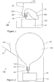
Figure 1 is a schematic diagram of a self-inflating balloon according to the present invention, before inflation; -
Figure 2 is a schematic diagram of the self-inflating balloon ofFigure 1 , after inflation; -
Figure 3 is a schematic diagram of another embodiment of a self-inflating balloon according to the present invention, after inflation; -
Figure 4 is a schematic diagram of the neck of the inflatable bag of an embodiment of a self-inflating balloon according to the present invention, provided with an illuminating means; and -
Figure 5 is a series of illustrations of one potential process of operating the self-inflating balloon of the present invention. -
Figure 1 shows a self-inflatingballoon 100 according to the present invention, provided with anenclosure 10. Theballoon 100 is adapted such that when the enclosure is opened, the balloon self-inflates. - The
enclosure 10 is a box provided with alid 12. In some embodiments, thelid 12 can be secured to thebox 10 at one edge. Within the enclosure is a container ofcompressed gas 14 and aninflatable bag 16. - The
inflatable bag 16 may be formed from a foil material such as a biaxially-oriented Polyethylene Terephthalate (BoPET) film or a BoPET film with an Ethylene Vinyl Alcohol (EVOH) gas barrier layer, and comprises aneck portion 161 and abody portion 162. Within theneck portion 161, there is provided a one-way valve 20 which is engagable with thegas valve 18. The one-way valve 20 is bonded to the inner sides of theneck portion 161 of theinflatable bag 16, such that the one-way valve 20 is the only passage through which gas can enter thebag 16. - The container of
compressed gas 14 is provided with agas valve 18, through which gas can leave thecontainer 14. The compressed gas may be helium. The gas valve is provided with a spring or other biasing means (not shown) operable to urge thegas valve 18 open. - Within the
enclosure 10 there is also provided apull tab trigger 22, wherein one end of thepull tab 22 is bonded to the underside of thelid 12 of theenclosure 10, and the other end is initially removably located in a position holding the spring or other biasing means (not shown) into a position that holds thegas valve 18 closed, preventing any gas passing therethrough. - In use, the user opens the
lid 12 of theenclosure 10 in order to inflate theballoon 16. Turning now toFigure 2 , opening thelid 12 of theenclosure 10 withdraws the pull tab trigger 22 from its initial position, allowing the spring to assume its biased position in which the gas valve is held open by the spring. Activating the trigger means allows the gas valve to open and therefore enables helium from thegas container 14 to enter theinflatable bag 16 and cause the inflatable bag to inflate. The one-way valve 20 and thegas valve 18 are releasably engagable, such that when sufficient gas has been introduced, the engagement means can be released. In this context, theballoon 16 can be separated from thegas valve 18 of the compressedgas container 14. Any suitable releasable attachment means may be used, such as a screw thread, friction fit, push button engagement means, perforated film securing means, or temporary adhesion pads. - In an alternative embodiment, the
gas valve 18 is provided with a spring or other biasing means (not shown) operable to urge the valve shut. The trigger means comprises a push button (not shown) operable to act against the biasing means when activated in order to open the gas valve and allow theinflatable bag 16 to be inflated. Release of the push button causes thegas valve 18 to revert to the closed position. - Turning now to
Figure 3 , the one-way valve 20 and thegas valve 18 have been released and are no longer engaged. In this context, theinflated bag 16 is able to float above theenclosure 10. The floatinginflated bag 16 is retained by way of atether 24, which is attached at one end to theinflated bag 16 by means of a knot or adhesive bond, and attached at the other end to thegas container 14. Thetether 24 may be any suitable flexible tether, such as a length of ribbon, string, or wire. Thetether 24 may be a length of thin wire (such as fishing wire) such that the tether cannot be easily seen.
Thegas container 14 acts as a weight to prevent theinflated bag 16 floating out of reach or to an undesired height. Thegas container 14 may be removed from theenclosure 10 or may be bonded thereto. In embodiments where thegas container 14 may be removed from theenclosure 10, thegas container 14 may be decorative. - There is also provided an illumination means 26. In this embodiment, the illumination means 26 is provided inside the
inflatable bag 16, at a distal end of thebody 16 of the bag. Theillumination device 26 has aprojection 28 whereby it is attached to the inside of the wall of theinflatable bag 16 by a clip, band or O-ring fitted onto the projection from outside the balloon. - An illumination means
trigger 30 is provided. The illumination meanstrigger 30 consists of apull tab 301 of insulating material and is provided on and bonded to the inside of theinflatable bag 16. The illumination means 26 is shown inFigure 3 in an activated state, wherein inflation of thebag 16 has moved theillumination device 26 away from thepull tab 301, therefore withdrawing it from its initial location and completing a circuit. Further details of pull tab activation of an illumination device provided at the distal end of a balloon can be found inWO2008110832 . - Turning now to
Figure 4 , an alternative arrangement is shown, wherein anillumination device 26 is provided in theneck 161 of theinflatable bag 16. In this context, theillumination device 26 is provided adjacent to the one-way valve 20. Theillumination device 26 is bonded to both the one-way valve 20 and the inner surface of theneck 161 of theinflatable bag 16, such that the one-way valve 20 is the only passage through which gas can enter thebag 16. In such an embodiment, theillumination device 26 is activated by use of any suitable trigger means 30. The trigger means 30 may be the same trigger as the inflation trigger, or may be a separately provided trigger of the same or of a different kind. - The
illumination device 26 may additionally be activated or controlled remotely. In such embodiments, the balloon may be inflated at a first time and theillumination device 26 may be activated at a second, later time. As an example, a balloon or balloons may be inflated as part of preparation for a party. Theillumination device 26 provided in each of the inflated balloons may then be subsequently activated by way of a remote control. In such embodiments, pressing a button or equivalent on a remote control sends out a control signal (typically a radio frequency (RF) or infrared signal) and theillumination device 26 is provided with a sensor that is capable of receiving said control signal. Subsequently, in response to the detection of the control signal theillumination device 26 is activated. The control signal may be operable to activate theillumination device 26 or the control signal may be operable to select a mode of activation such as constant illumination or intermittent illumination. - An audio player (not shown) operable to output sounds is provided in the neck of the
inflatable bag 16. The audio player is controlled in response to the activation of a trigger means. In this embodiment, the audio player trigger means is provided integrally with the illumination means, and the audio player trigger means is the same as the illumination device trigger means. - Turning now to
Figure 5 , a schematic diagram of the various steps of activating the self-inflating balloon are shown.Figure 5A shows theenclosure 10 in its initial position, wherein thelid 12 is in the closed position. InFigure 5B , theenclosure 10 is opened and the trigger means 22 is activated. Activation of the trigger means 22 causes the balloon to inflate, as shown inFigure 5C. Figure 5D shows an embodiment where theinflatable bag 16 is inflated and the body inflatedbag 16 sits above theenclosure 10 andcompressed gas container 14. - In cases where a lighter than air gas is used to inflate the bag, the steps of activating the self-inflating balloon continue to
Figure 5E. Figure 5E shows an embodiment where the gas valve (not shown) and one-way valve (not shown) positioned in theneck portion 161 are releasably engagable and have been released upon inflation of theinflatable bag 16. Theinflatable bag 16 is retained by way of aflexible tether 24. - In alternative embodiments, the gas used may be a hydrogenated chlorofluorocarbon compound. The
inflatable bag 16 may be made of rubber latex and the body portion thereof may be substantially spherical. Obviously, since a hydrogenated chlorofluorocarbon compound is not lighter than air, a balloon inflated with such a gas would not float. Since the balloon would not float, there is no need for a tether to be provided. However, the provision of a tether would enable the user to easily tie the balloon to an object and may be included in such embodiments. In such embodiments, the enclosure may be a lightweight flexible bag. Additionally in such embodiments theneck portion 161 of theinflatable bag 16 may not be provided with a one-way valve. Thegas valve 18 may engage directly with theneck portion 161 of theinflatable bag 16 and remain engaged throughout the use of the balloon. In such embodiments, the inflation trigger means may comprise any suitable trigger means. In particular, the trigger means may comprise a pull tab of material initially in contact with thegas valve 18. Withdrawing the pull tab trigger may release a spring biased to open thegas valve 18, allowing gas to enter and inflate theinflatable bag 16. - The skilled man will appreciate that any features of embodiments described herein as using helium (or another lighter than air gas) such as but not limited to the particular trigger means provided, the provision of a one-way valve in the neck of the inflatable bag, and the provision of a tether, may equally be adapted to an embodiment of the present invention as herein described as using a heavier than air gas, and vice versa.
- The above embodiments are described by way of example only. Many variations are possible without departing from the scope of the invention as defined in the appended claims.
Claims (13)
- A self-inflating balloon (100) comprising: an inflatable bag (16) of substantially air impervious material, the inflatable bag (16) comprising a neck portion (161) and a body portion (162); a container (14) of compressed gas; trigger means (22) associated with the container (14) operable to allow gas from the container (14) to inflate the bag (16); and an enclosure (10) in which the bag (16), the container (14) and the trigger means (22) are housed, wherein: opening the enclosure (10) activates the trigger means (22) or provides access for activation of the trigger means (22); and the gas container (14) is provided with a container gas valve (18) through which the compressed gas exits the container (14); and characterized in that: the neck portion (161) of the inflatable bag (16) is provided with a one-way valve (20) that is engagable with the gas container valve (18); the balloon (100) additionally comprises an illumination device (26); the illumination device (26) is provided in the neck portion (161) of the inflatable bag (16); and the illumination device (26) is bonded between the one-way valve (20) and an inner surface of the neck portion (161), wherein the one-way valve (20) is the only passage through which gas can enter the bag (16).
- A self-inflating balloon (100) as claimed in any preceding claim, wherein the illumination device (26) is one or more light emitting diodes (LED).
- A self-inflating balloon (100) as claimed in any preceding claim, wherein the illumination device (26) is provided with a power supply comprising at least one battery or an energy scavenging means.
- A self-inflating balloon (100) as claimed in any preceding claim, wherein the illumination device (26) is controlled in response to the activation of a trigger means (30).
- A self-inflating balloon (100) as claimed in claim 4, when dependent directly or indirectly upon claim 2, wherein the illumination device trigger means (30) comprises an insulating material initially located between the battery or batteries and the LED, said material being capable of being withdrawn from extending between the battery or batteries in order to complete a circuit.
- A self-inflating balloon (100) as claimed in claim 4, wherein the illumination device trigger means (30) comprises a switch or button.
- A self-inflating balloon (100) as claimed in claim 4, wherein the illumination device trigger means (30) comprises a sensor operable to receive a control signal.
- A self-inflating balloon (100) as claimed in any preceding claim, additionally comprising an audio player operable to output sounds.
- A self-inflating balloon (100) as claimed in claim 8, wherein the audio player is controlled in response to the activation of a trigger means.
- A self-inflating balloon (100) as claimed in claim 9, wherein the audio player trigger means comprises a switch or button.
- A self-inflating balloon (100) as claimed in claim 9, wherein the audio player trigger means comprises a sensor operable to receive a control signal.
- A self-inflating balloon (100) as claimed in any preceding claim, wherein the enclosure (10) is a box with a removable lid (12) and the inflation trigger means (22) is attached at at least one end to the underside of the lid (12).
- A self-inflating balloon (100) as claimed in any of claims 1 to 12, wherein the enclosure (10) is a flexible bag and the inflation trigger means (22) is attached at at least one end to the inner surface of the flexible bag.
Applications Claiming Priority (2)
| Application Number | Priority Date | Filing Date | Title |
|---|---|---|---|
| GB1407064.3A GB2525394A (en) | 2014-04-22 | 2014-04-22 | Self Inflating Balloon |
| PCT/GB2015/051187 WO2015162420A1 (en) | 2014-04-22 | 2015-04-22 | Self inflating balloon |
Publications (2)
| Publication Number | Publication Date |
|---|---|
| EP3134192A1 EP3134192A1 (en) | 2017-03-01 |
| EP3134192B1 true EP3134192B1 (en) | 2020-09-30 |
Family
ID=50929018
Family Applications (1)
| Application Number | Title | Priority Date | Filing Date |
|---|---|---|---|
| EP15727708.8A Active EP3134192B1 (en) | 2014-04-22 | 2015-04-22 | Self inflating balloon |
Country Status (6)
| Country | Link |
|---|---|
| US (1) | US20170043271A1 (en) |
| EP (1) | EP3134192B1 (en) |
| CN (1) | CN106457051A (en) |
| CA (1) | CA2983245A1 (en) |
| GB (1) | GB2525394A (en) |
| WO (1) | WO2015162420A1 (en) |
Families Citing this family (9)
| Publication number | Priority date | Publication date | Assignee | Title |
|---|---|---|---|---|
| US10328354B2 (en) * | 2017-02-27 | 2019-06-25 | Cardalloon Co Llc | Gift box with self-inflating balloon |
| US10751439B2 (en) * | 2017-05-11 | 2020-08-25 | William Paul Warkentin | Vent balloon |
| CN108644606B (en) * | 2018-07-19 | 2023-06-23 | 国家海洋局第一海洋研究所 | Automatic inflation and release device for shipborne sounding balloon and use method |
| US11358718B2 (en) * | 2018-08-21 | 2022-06-14 | Seung Hee CHOI | Low-altitude unmanned aerial vehicle surveillance system |
| CN110585743A (en) * | 2019-09-29 | 2019-12-20 | 西安图唯谷创新科技有限公司 | Automatic balloon inflation and deflation device and method |
| CN112156482A (en) * | 2020-09-28 | 2021-01-01 | 西安航空职业技术学院 | Aerodynamic toy plane and use method thereof |
| CN113975827A (en) * | 2021-11-30 | 2022-01-28 | 义乌龙创尤品家居用品有限公司 | Luminous balloon |
| US11926465B2 (en) * | 2022-05-03 | 2024-03-12 | Party Lovers Inc. | Process and apparatus for carrier shipping and longer storage of helium party balloons |
| DE102022129848B4 (en) | 2022-11-11 | 2024-02-29 | AirMarker AG | Signaling device |
Family Cites Families (33)
| Publication number | Priority date | Publication date | Assignee | Title |
|---|---|---|---|---|
| US3174455A (en) * | 1963-04-16 | 1965-03-23 | Gayle O Peterson | Inflatable signal balloon |
| US3938466A (en) * | 1974-10-07 | 1976-02-17 | The Raymond Lee Organization, Inc. | Location indicating device |
| US4416433A (en) * | 1981-07-13 | 1983-11-22 | Bellina Joseph H | Signal balloon dispensing apparatus |
| US4586456A (en) * | 1984-06-01 | 1986-05-06 | Forward Ross M | Inflatable balloon distress marker having small article containing compartment therein |
| US4911674A (en) * | 1985-08-19 | 1990-03-27 | Specialty Advertising, Inc. | Self sealing valve for inflating toy balloons |
| US4787575A (en) * | 1987-02-25 | 1988-11-29 | David L. Huskey | Signal balloon device |
| US4800835A (en) * | 1988-03-10 | 1989-01-31 | Radarfind, Inc. | Locator device |
| US4920674A (en) * | 1988-11-14 | 1990-05-01 | Shaeffer Henry W | Inflatable communication device |
| US4911647A (en) * | 1989-01-10 | 1990-03-27 | Tandem Computers Incorporated | Insertion/extraction mechanism for blind pluggable modules |
| US4903958A (en) * | 1989-01-23 | 1990-02-27 | Fernando DiCarlo | Balloon amusement device |
| US5083771A (en) * | 1990-04-16 | 1992-01-28 | Tyner Michael R | Novelty item |
| US5108337A (en) * | 1990-11-05 | 1992-04-28 | Sloan John D | Inflatable balloon system |
| US5240449A (en) * | 1990-11-05 | 1993-08-31 | Innovative Impressions, Inc. | Inflatable balloon system |
| US5236383A (en) * | 1991-11-27 | 1993-08-17 | I & K Trading Corporation | Illuminated toy ball |
| CA2099390C (en) * | 1992-07-02 | 1998-05-26 | Mark J. Van Dyke | Packaged balloon and greeting card |
| US5582127A (en) * | 1994-04-07 | 1996-12-10 | Lee Willis | Rescue device and method |
| US5852889A (en) * | 1994-08-31 | 1998-12-29 | Rinaldi; Robert | Greeting card with self-inflating balloon |
| US5579813A (en) * | 1995-03-28 | 1996-12-03 | Watts; Bruce D. | Self-triggering inflatable balloon device |
| FR2754040B1 (en) * | 1996-10-02 | 1998-11-13 | Airstar | LIGHTING BALL WITH INFLATABLE BODY AND INTEGRATED CONTROL UNIT |
| US6109203A (en) * | 1997-07-03 | 2000-08-29 | Harold D. Sorensen | Deployable personal locator device |
| US5935013A (en) * | 1997-12-02 | 1999-08-10 | Bruce D. Watts | Self-triggering inflatable balloon device and valve therefor |
| US6106135A (en) * | 1998-02-11 | 2000-08-22 | Zingale; Robert | Decorative illuminated balloons |
| US6302171B1 (en) * | 2000-11-08 | 2001-10-16 | Connie Watts | Self-triggering inflatable balloon device and valve therefor having an improved puncture stake |
| US20040127138A1 (en) * | 2002-12-27 | 2004-07-01 | Chung-Tao Huang | Inflatable bag having light emitting device |
| GB2434777B (en) * | 2006-02-02 | 2010-11-24 | Mellowgraphic Ltd | Automatically inflatable flotation device |
| US20080032590A1 (en) * | 2006-07-21 | 2008-02-07 | Jie-Yi Co., Ltd. | Balloon structure |
| GB2452236A (en) * | 2007-03-09 | 2009-03-04 | Mellowgraphic Ltd | Party balloon with illumination device |
| US7870625B2 (en) * | 2007-04-24 | 2011-01-18 | Melanee Omar | Mat for child development |
| US20120067453A1 (en) * | 2010-09-08 | 2012-03-22 | Ramere Donna A | Portable Balloon Filling Device and Method |
| GB2489025B (en) * | 2011-03-16 | 2015-01-14 | Seatriever Int Holdings Ltd | Illuminated balloon |
| CN202289462U (en) * | 2011-10-14 | 2012-07-04 | 深圳概念贸易有限公司 | Balloon with illuminating/sounding device |
| CN102527057B (en) * | 2012-01-20 | 2015-01-14 | 深圳概念贸易有限公司 | Balloon inflating device with illuminating/sounding effect |
| US9192872B2 (en) * | 2013-09-05 | 2015-11-24 | Cool Glow LLC | Apparatus for sealing and illuminating a balloon |
-
2014
- 2014-04-22 GB GB1407064.3A patent/GB2525394A/en not_active Withdrawn
-
2015
- 2015-04-22 US US15/305,902 patent/US20170043271A1/en not_active Abandoned
- 2015-04-22 CN CN201580033657.0A patent/CN106457051A/en active Pending
- 2015-04-22 CA CA2983245A patent/CA2983245A1/en not_active Abandoned
- 2015-04-22 WO PCT/GB2015/051187 patent/WO2015162420A1/en active Application Filing
- 2015-04-22 EP EP15727708.8A patent/EP3134192B1/en active Active
Non-Patent Citations (1)
| Title |
|---|
| None * |
Also Published As
| Publication number | Publication date |
|---|---|
| CN106457051A (en) | 2017-02-22 |
| US20170043271A1 (en) | 2017-02-16 |
| GB2525394A (en) | 2015-10-28 |
| EP3134192A1 (en) | 2017-03-01 |
| WO2015162420A1 (en) | 2015-10-29 |
| CA2983245A1 (en) | 2015-10-29 |
| GB201407064D0 (en) | 2014-06-04 |
Similar Documents
| Publication | Publication Date | Title |
|---|---|---|
| EP3134192B1 (en) | Self inflating balloon | |
| US9192872B2 (en) | Apparatus for sealing and illuminating a balloon | |
| US3002490A (en) | Survival kit | |
| US5049106A (en) | Self-contained, self-inflating novelty balloon | |
| CN101678240B (en) | Party balloon with illumination device | |
| US4416433A (en) | Signal balloon dispensing apparatus | |
| US6523778B2 (en) | Illuminated emergency signaling device and flying balloon | |
| US5245943A (en) | Land or water S.O.S. signaling device | |
| US3381655A (en) | Rescue balloon | |
| US5083771A (en) | Novelty item | |
| US2083431A (en) | Donkey's bray | |
| US8070543B1 (en) | Inflatable life raft with detachable accessory pouch | |
| US20140295728A1 (en) | Balloon Inflation, Illumination and Holding Device | |
| US20140096867A1 (en) | Balloon Inflation, Illumination and Holding Device | |
| US8508382B1 (en) | Light emitting inflatable safety beacon | |
| US2698496A (en) | Self-inflating stable plastic figure | |
| US9186594B2 (en) | Illuminated balloon | |
| US20120214371A1 (en) | Inflatable Rescue Device | |
| US9162738B1 (en) | Inflatable life raft with detachable accessory pouch | |
| US2842090A (en) | Combination signaling device | |
| US2395006A (en) | Signal balloon | |
| US20130247892A1 (en) | Inflatable Life Preserver And Associated Delivery System | |
| US20090094867A1 (en) | Compact rescue signal device | |
| US20120171911A1 (en) | Inflatable diving safety marker | |
| US2409166A (en) | Signal device |
Legal Events
| Date | Code | Title | Description |
|---|---|---|---|
| STAA | Information on the status of an ep patent application or granted ep patent |
Free format text: STATUS: THE INTERNATIONAL PUBLICATION HAS BEEN MADE |
|
| PUAI | Public reference made under article 153(3) epc to a published international application that has entered the european phase |
Free format text: ORIGINAL CODE: 0009012 |
|
| STAA | Information on the status of an ep patent application or granted ep patent |
Free format text: STATUS: REQUEST FOR EXAMINATION WAS MADE |
|
| 17P | Request for examination filed |
Effective date: 20161122 |
|
| AK | Designated contracting states |
Kind code of ref document: A1 Designated state(s): AL AT BE BG CH CY CZ DE DK EE ES FI FR GB GR HR HU IE IS IT LI LT LU LV MC MK MT NL NO PL PT RO RS SE SI SK SM TR |
|
| AX | Request for extension of the european patent |
Extension state: BA ME |
|
| DAV | Request for validation of the european patent (deleted) | ||
| DAX | Request for extension of the european patent (deleted) | ||
| STAA | Information on the status of an ep patent application or granted ep patent |
Free format text: STATUS: EXAMINATION IS IN PROGRESS |
|
| 17Q | First examination report despatched |
Effective date: 20190218 |
|
| GRAP | Despatch of communication of intention to grant a patent |
Free format text: ORIGINAL CODE: EPIDOSNIGR1 |
|
| STAA | Information on the status of an ep patent application or granted ep patent |
Free format text: STATUS: GRANT OF PATENT IS INTENDED |
|
| INTG | Intention to grant announced |
Effective date: 20191220 |
|
| GRAS | Grant fee paid |
Free format text: ORIGINAL CODE: EPIDOSNIGR3 |
|
| GRAA | (expected) grant |
Free format text: ORIGINAL CODE: 0009210 |
|
| STAA | Information on the status of an ep patent application or granted ep patent |
Free format text: STATUS: THE PATENT HAS BEEN GRANTED |
|
| AK | Designated contracting states |
Kind code of ref document: B1 Designated state(s): AL AT BE BG CH CY CZ DE DK EE ES FI FR GB GR HR HU IE IS IT LI LT LU LV MC MK MT NL NO PL PT RO RS SE SI SK SM TR |
|
| REG | Reference to a national code |
Ref country code: CH Ref legal event code: EP Ref country code: GB Ref legal event code: FG4D |
|
| REG | Reference to a national code |
Ref country code: AT Ref legal event code: REF Ref document number: 1318209 Country of ref document: AT Kind code of ref document: T Effective date: 20201015 |
|
| REG | Reference to a national code |
Ref country code: DE Ref legal event code: R096 Ref document number: 602015059792 Country of ref document: DE |
|
| REG | Reference to a national code |
Ref country code: IE Ref legal event code: FG4D |
|
| PG25 | Lapsed in a contracting state [announced via postgrant information from national office to epo] |
Ref country code: HR Free format text: LAPSE BECAUSE OF FAILURE TO SUBMIT A TRANSLATION OF THE DESCRIPTION OR TO PAY THE FEE WITHIN THE PRESCRIBED TIME-LIMIT Effective date: 20200930 Ref country code: BG Free format text: LAPSE BECAUSE OF FAILURE TO SUBMIT A TRANSLATION OF THE DESCRIPTION OR TO PAY THE FEE WITHIN THE PRESCRIBED TIME-LIMIT Effective date: 20201230 Ref country code: SE Free format text: LAPSE BECAUSE OF FAILURE TO SUBMIT A TRANSLATION OF THE DESCRIPTION OR TO PAY THE FEE WITHIN THE PRESCRIBED TIME-LIMIT Effective date: 20200930 Ref country code: FI Free format text: LAPSE BECAUSE OF FAILURE TO SUBMIT A TRANSLATION OF THE DESCRIPTION OR TO PAY THE FEE WITHIN THE PRESCRIBED TIME-LIMIT Effective date: 20200930 Ref country code: NO Free format text: LAPSE BECAUSE OF FAILURE TO SUBMIT A TRANSLATION OF THE DESCRIPTION OR TO PAY THE FEE WITHIN THE PRESCRIBED TIME-LIMIT Effective date: 20201230 Ref country code: GR Free format text: LAPSE BECAUSE OF FAILURE TO SUBMIT A TRANSLATION OF THE DESCRIPTION OR TO PAY THE FEE WITHIN THE PRESCRIBED TIME-LIMIT Effective date: 20201231 |
|
| REG | Reference to a national code |
Ref country code: AT Ref legal event code: MK05 Ref document number: 1318209 Country of ref document: AT Kind code of ref document: T Effective date: 20200930 |
|
| PG25 | Lapsed in a contracting state [announced via postgrant information from national office to epo] |
Ref country code: RS Free format text: LAPSE BECAUSE OF FAILURE TO SUBMIT A TRANSLATION OF THE DESCRIPTION OR TO PAY THE FEE WITHIN THE PRESCRIBED TIME-LIMIT Effective date: 20200930 Ref country code: LV Free format text: LAPSE BECAUSE OF FAILURE TO SUBMIT A TRANSLATION OF THE DESCRIPTION OR TO PAY THE FEE WITHIN THE PRESCRIBED TIME-LIMIT Effective date: 20200930 |
|
| REG | Reference to a national code |
Ref country code: NL Ref legal event code: MP Effective date: 20200930 |
|
| REG | Reference to a national code |
Ref country code: LT Ref legal event code: MG4D |
|
| PG25 | Lapsed in a contracting state [announced via postgrant information from national office to epo] |
Ref country code: CZ Free format text: LAPSE BECAUSE OF FAILURE TO SUBMIT A TRANSLATION OF THE DESCRIPTION OR TO PAY THE FEE WITHIN THE PRESCRIBED TIME-LIMIT Effective date: 20200930 Ref country code: NL Free format text: LAPSE BECAUSE OF FAILURE TO SUBMIT A TRANSLATION OF THE DESCRIPTION OR TO PAY THE FEE WITHIN THE PRESCRIBED TIME-LIMIT Effective date: 20200930 Ref country code: PT Free format text: LAPSE BECAUSE OF FAILURE TO SUBMIT A TRANSLATION OF THE DESCRIPTION OR TO PAY THE FEE WITHIN THE PRESCRIBED TIME-LIMIT Effective date: 20210201 Ref country code: LT Free format text: LAPSE BECAUSE OF FAILURE TO SUBMIT A TRANSLATION OF THE DESCRIPTION OR TO PAY THE FEE WITHIN THE PRESCRIBED TIME-LIMIT Effective date: 20200930 Ref country code: RO Free format text: LAPSE BECAUSE OF FAILURE TO SUBMIT A TRANSLATION OF THE DESCRIPTION OR TO PAY THE FEE WITHIN THE PRESCRIBED TIME-LIMIT Effective date: 20200930 Ref country code: SM Free format text: LAPSE BECAUSE OF FAILURE TO SUBMIT A TRANSLATION OF THE DESCRIPTION OR TO PAY THE FEE WITHIN THE PRESCRIBED TIME-LIMIT Effective date: 20200930 Ref country code: EE Free format text: LAPSE BECAUSE OF FAILURE TO SUBMIT A TRANSLATION OF THE DESCRIPTION OR TO PAY THE FEE WITHIN THE PRESCRIBED TIME-LIMIT Effective date: 20200930 |
|
| PG25 | Lapsed in a contracting state [announced via postgrant information from national office to epo] |
Ref country code: IS Free format text: LAPSE BECAUSE OF FAILURE TO SUBMIT A TRANSLATION OF THE DESCRIPTION OR TO PAY THE FEE WITHIN THE PRESCRIBED TIME-LIMIT Effective date: 20210130 Ref country code: PL Free format text: LAPSE BECAUSE OF FAILURE TO SUBMIT A TRANSLATION OF THE DESCRIPTION OR TO PAY THE FEE WITHIN THE PRESCRIBED TIME-LIMIT Effective date: 20200930 Ref country code: ES Free format text: LAPSE BECAUSE OF FAILURE TO SUBMIT A TRANSLATION OF THE DESCRIPTION OR TO PAY THE FEE WITHIN THE PRESCRIBED TIME-LIMIT Effective date: 20200930 Ref country code: AL Free format text: LAPSE BECAUSE OF FAILURE TO SUBMIT A TRANSLATION OF THE DESCRIPTION OR TO PAY THE FEE WITHIN THE PRESCRIBED TIME-LIMIT Effective date: 20200930 Ref country code: AT Free format text: LAPSE BECAUSE OF FAILURE TO SUBMIT A TRANSLATION OF THE DESCRIPTION OR TO PAY THE FEE WITHIN THE PRESCRIBED TIME-LIMIT Effective date: 20200930 |
|
| PG25 | Lapsed in a contracting state [announced via postgrant information from national office to epo] |
Ref country code: SK Free format text: LAPSE BECAUSE OF FAILURE TO SUBMIT A TRANSLATION OF THE DESCRIPTION OR TO PAY THE FEE WITHIN THE PRESCRIBED TIME-LIMIT Effective date: 20200930 |
|
| REG | Reference to a national code |
Ref country code: DE Ref legal event code: R097 Ref document number: 602015059792 Country of ref document: DE |
|
| PLBE | No opposition filed within time limit |
Free format text: ORIGINAL CODE: 0009261 |
|
| STAA | Information on the status of an ep patent application or granted ep patent |
Free format text: STATUS: NO OPPOSITION FILED WITHIN TIME LIMIT |
|
| PG25 | Lapsed in a contracting state [announced via postgrant information from national office to epo] |
Ref country code: DK Free format text: LAPSE BECAUSE OF FAILURE TO SUBMIT A TRANSLATION OF THE DESCRIPTION OR TO PAY THE FEE WITHIN THE PRESCRIBED TIME-LIMIT Effective date: 20200930 |
|
| 26N | No opposition filed |
Effective date: 20210701 |
|
| PG25 | Lapsed in a contracting state [announced via postgrant information from national office to epo] |
Ref country code: IT Free format text: LAPSE BECAUSE OF FAILURE TO SUBMIT A TRANSLATION OF THE DESCRIPTION OR TO PAY THE FEE WITHIN THE PRESCRIBED TIME-LIMIT Effective date: 20200930 |
|
| REG | Reference to a national code |
Ref country code: DE Ref legal event code: R119 Ref document number: 602015059792 Country of ref document: DE |
|
| PG25 | Lapsed in a contracting state [announced via postgrant information from national office to epo] |
Ref country code: MC Free format text: LAPSE BECAUSE OF FAILURE TO SUBMIT A TRANSLATION OF THE DESCRIPTION OR TO PAY THE FEE WITHIN THE PRESCRIBED TIME-LIMIT Effective date: 20200930 Ref country code: SI Free format text: LAPSE BECAUSE OF FAILURE TO SUBMIT A TRANSLATION OF THE DESCRIPTION OR TO PAY THE FEE WITHIN THE PRESCRIBED TIME-LIMIT Effective date: 20200930 |
|
| PG25 | Lapsed in a contracting state [announced via postgrant information from national office to epo] |
Ref country code: LU Free format text: LAPSE BECAUSE OF NON-PAYMENT OF DUE FEES Effective date: 20210422 |
|
| REG | Reference to a national code |
Ref country code: BE Ref legal event code: MM Effective date: 20210430 |
|
| PG25 | Lapsed in a contracting state [announced via postgrant information from national office to epo] |
Ref country code: DE Free format text: LAPSE BECAUSE OF NON-PAYMENT OF DUE FEES Effective date: 20211103 Ref country code: FR Free format text: LAPSE BECAUSE OF NON-PAYMENT OF DUE FEES Effective date: 20210430 Ref country code: LI Free format text: LAPSE BECAUSE OF NON-PAYMENT OF DUE FEES Effective date: 20210430 Ref country code: CH Free format text: LAPSE BECAUSE OF NON-PAYMENT OF DUE FEES Effective date: 20210430 |
|
| PG25 | Lapsed in a contracting state [announced via postgrant information from national office to epo] |
Ref country code: IE Free format text: LAPSE BECAUSE OF NON-PAYMENT OF DUE FEES Effective date: 20210422 |
|
| PG25 | Lapsed in a contracting state [announced via postgrant information from national office to epo] |
Ref country code: IS Free format text: LAPSE BECAUSE OF FAILURE TO SUBMIT A TRANSLATION OF THE DESCRIPTION OR TO PAY THE FEE WITHIN THE PRESCRIBED TIME-LIMIT Effective date: 20210130 |
|
| PG25 | Lapsed in a contracting state [announced via postgrant information from national office to epo] |
Ref country code: BE Free format text: LAPSE BECAUSE OF NON-PAYMENT OF DUE FEES Effective date: 20210430 |
|
| PG25 | Lapsed in a contracting state [announced via postgrant information from national office to epo] |
Ref country code: HU Free format text: LAPSE BECAUSE OF FAILURE TO SUBMIT A TRANSLATION OF THE DESCRIPTION OR TO PAY THE FEE WITHIN THE PRESCRIBED TIME-LIMIT; INVALID AB INITIO Effective date: 20150422 |
|
| PGFP | Annual fee paid to national office [announced via postgrant information from national office to epo] |
Ref country code: GB Payment date: 20230328 Year of fee payment: 9 |
|
| PG25 | Lapsed in a contracting state [announced via postgrant information from national office to epo] |
Ref country code: CY Free format text: LAPSE BECAUSE OF FAILURE TO SUBMIT A TRANSLATION OF THE DESCRIPTION OR TO PAY THE FEE WITHIN THE PRESCRIBED TIME-LIMIT Effective date: 20200930 |
|
| P01 | Opt-out of the competence of the unified patent court (upc) registered |
Effective date: 20230526 |