EP3132814A1 - Reduced-pressure, multi-orientation, liquid-collection canister - Google Patents
Reduced-pressure, multi-orientation, liquid-collection canister Download PDFInfo
- Publication number
- EP3132814A1 EP3132814A1 EP16192619.1A EP16192619A EP3132814A1 EP 3132814 A1 EP3132814 A1 EP 3132814A1 EP 16192619 A EP16192619 A EP 16192619A EP 3132814 A1 EP3132814 A1 EP 3132814A1
- Authority
- EP
- European Patent Office
- Prior art keywords
- liquid
- canister
- reduced pressure
- clause
- elongated member
- Prior art date
- Legal status (The legal status is an assumption and is not a legal conclusion. Google has not performed a legal analysis and makes no representation as to the accuracy of the status listed.)
- Granted
Links
- 239000007788 liquid Substances 0.000 claims abstract description 202
- 238000004891 communication Methods 0.000 claims abstract description 122
- 239000012530 fluid Substances 0.000 claims description 66
- 239000000463 material Substances 0.000 claims description 57
- 230000008867 communication pathway Effects 0.000 claims description 29
- 229920000295 expanded polytetrafluoroethylene Polymers 0.000 claims description 16
- 239000012528 membrane Substances 0.000 abstract description 35
- 210000001519 tissue Anatomy 0.000 description 95
- 239000007789 gas Substances 0.000 description 66
- 206010052428 Wound Diseases 0.000 description 23
- 208000027418 Wounds and injury Diseases 0.000 description 23
- 238000009826 distribution Methods 0.000 description 22
- 238000000034 method Methods 0.000 description 21
- 230000002209 hydrophobic effect Effects 0.000 description 18
- OKTJSMMVPCPJKN-UHFFFAOYSA-N Carbon Chemical compound [C] OKTJSMMVPCPJKN-UHFFFAOYSA-N 0.000 description 10
- 239000000853 adhesive Substances 0.000 description 8
- 230000001070 adhesive effect Effects 0.000 description 8
- 230000008901 benefit Effects 0.000 description 7
- 210000000416 exudates and transudate Anatomy 0.000 description 6
- 238000001179 sorption measurement Methods 0.000 description 6
- 239000006260 foam Substances 0.000 description 5
- 230000015572 biosynthetic process Effects 0.000 description 4
- 230000010261 cell growth Effects 0.000 description 4
- 238000013461 design Methods 0.000 description 4
- 230000005484 gravity Effects 0.000 description 4
- 239000000203 mixture Substances 0.000 description 4
- 229920000728 polyester Polymers 0.000 description 4
- 229920001343 polytetrafluoroethylene Polymers 0.000 description 4
- 239000004810 polytetrafluoroethylene Substances 0.000 description 4
- 239000000126 substance Substances 0.000 description 4
- 229920000954 Polyglycolide Polymers 0.000 description 3
- 239000000835 fiber Substances 0.000 description 3
- 229920003023 plastic Polymers 0.000 description 3
- 239000004033 plastic Substances 0.000 description 3
- 239000004633 polyglycolic acid Substances 0.000 description 3
- 238000009420 retrofitting Methods 0.000 description 3
- 238000000926 separation method Methods 0.000 description 3
- 238000007493 shaping process Methods 0.000 description 3
- XLYOFNOQVPJJNP-UHFFFAOYSA-N water Substances O XLYOFNOQVPJJNP-UHFFFAOYSA-N 0.000 description 3
- 229920006397 acrylic thermoplastic Polymers 0.000 description 2
- 230000007423 decrease Effects 0.000 description 2
- 239000006261 foam material Substances 0.000 description 2
- 230000012010 growth Effects 0.000 description 2
- 230000002706 hydrostatic effect Effects 0.000 description 2
- 230000013011 mating Effects 0.000 description 2
- 239000002184 metal Substances 0.000 description 2
- 229910052751 metal Inorganic materials 0.000 description 2
- 229920003229 poly(methyl methacrylate) Polymers 0.000 description 2
- 239000004626 polylactic acid Substances 0.000 description 2
- 229920000098 polyolefin Polymers 0.000 description 2
- 239000011148 porous material Substances 0.000 description 2
- 238000012545 processing Methods 0.000 description 2
- 230000009467 reduction Effects 0.000 description 2
- ISXSCDLOGDJUNJ-UHFFFAOYSA-N tert-butyl prop-2-enoate Chemical compound CC(C)(C)OC(=O)C=C ISXSCDLOGDJUNJ-UHFFFAOYSA-N 0.000 description 2
- 238000002560 therapeutic procedure Methods 0.000 description 2
- 238000003466 welding Methods 0.000 description 2
- 241000157282 Aesculus Species 0.000 description 1
- 235000014653 Carica parviflora Nutrition 0.000 description 1
- 241000243321 Cnidaria Species 0.000 description 1
- 102000008186 Collagen Human genes 0.000 description 1
- 108010035532 Collagen Proteins 0.000 description 1
- 206010063560 Excessive granulation tissue Diseases 0.000 description 1
- 239000004721 Polyphenylene oxide Substances 0.000 description 1
- 229920005830 Polyurethane Foam Polymers 0.000 description 1
- 239000004372 Polyvinyl alcohol Substances 0.000 description 1
- 230000002745 absorbent Effects 0.000 description 1
- 239000002250 absorbent Substances 0.000 description 1
- 210000000577 adipose tissue Anatomy 0.000 description 1
- 238000013459 approach Methods 0.000 description 1
- 230000004888 barrier function Effects 0.000 description 1
- 230000005540 biological transmission Effects 0.000 description 1
- 239000008280 blood Substances 0.000 description 1
- 210000004369 blood Anatomy 0.000 description 1
- 230000017531 blood circulation Effects 0.000 description 1
- 239000007767 bonding agent Substances 0.000 description 1
- 210000000988 bone and bone Anatomy 0.000 description 1
- 229910000389 calcium phosphate Inorganic materials 0.000 description 1
- 239000001506 calcium phosphate Substances 0.000 description 1
- 235000011010 calcium phosphates Nutrition 0.000 description 1
- 150000004649 carbonic acid derivatives Chemical class 0.000 description 1
- 210000000845 cartilage Anatomy 0.000 description 1
- 230000008859 change Effects 0.000 description 1
- 229920001436 collagen Polymers 0.000 description 1
- 230000005494 condensation Effects 0.000 description 1
- 238000009833 condensation Methods 0.000 description 1
- 210000002808 connective tissue Anatomy 0.000 description 1
- 230000007547 defect Effects 0.000 description 1
- 230000002950 deficient Effects 0.000 description 1
- 238000011161 development Methods 0.000 description 1
- 230000009977 dual effect Effects 0.000 description 1
- 230000002500 effect on skin Effects 0.000 description 1
- 230000000694 effects Effects 0.000 description 1
- 210000000981 epithelium Anatomy 0.000 description 1
- 229920002313 fluoropolymer Polymers 0.000 description 1
- 239000004811 fluoropolymer Substances 0.000 description 1
- 239000011888 foil Substances 0.000 description 1
- 230000006870 function Effects 0.000 description 1
- 238000005469 granulation Methods 0.000 description 1
- 230000003179 granulation Effects 0.000 description 1
- 210000001126 granulation tissue Anatomy 0.000 description 1
- 230000035876 healing Effects 0.000 description 1
- 235000010181 horse chestnut Nutrition 0.000 description 1
- 239000000017 hydrogel Substances 0.000 description 1
- 230000005660 hydrophilic surface Effects 0.000 description 1
- 125000002887 hydroxy group Chemical group [H]O* 0.000 description 1
- 208000015181 infectious disease Diseases 0.000 description 1
- 230000002458 infectious effect Effects 0.000 description 1
- 230000001788 irregular Effects 0.000 description 1
- 210000003041 ligament Anatomy 0.000 description 1
- 238000004519 manufacturing process Methods 0.000 description 1
- 230000007246 mechanism Effects 0.000 description 1
- 150000002739 metals Chemical class 0.000 description 1
- 230000005012 migration Effects 0.000 description 1
- 238000013508 migration Methods 0.000 description 1
- 238000012986 modification Methods 0.000 description 1
- 230000004048 modification Effects 0.000 description 1
- 210000003205 muscle Anatomy 0.000 description 1
- 238000009581 negative-pressure wound therapy Methods 0.000 description 1
- 230000001537 neural effect Effects 0.000 description 1
- 229920001778 nylon Polymers 0.000 description 1
- 210000000056 organ Anatomy 0.000 description 1
- 206010033675 panniculitis Diseases 0.000 description 1
- 230000037361 pathway Effects 0.000 description 1
- 210000002381 plasma Anatomy 0.000 description 1
- 238000009832 plasma treatment Methods 0.000 description 1
- 239000002985 plastic film Substances 0.000 description 1
- 229920000747 poly(lactic acid) Polymers 0.000 description 1
- 229920002647 polyamide Polymers 0.000 description 1
- 239000004417 polycarbonate Substances 0.000 description 1
- 229920000515 polycarbonate Polymers 0.000 description 1
- 229920000570 polyether Polymers 0.000 description 1
- -1 polytetrafluoroethylene Polymers 0.000 description 1
- 229920002635 polyurethane Polymers 0.000 description 1
- 239000004814 polyurethane Substances 0.000 description 1
- 239000011496 polyurethane foam Substances 0.000 description 1
- 229920002451 polyvinyl alcohol Polymers 0.000 description 1
- 230000008569 process Effects 0.000 description 1
- 238000007789 sealing Methods 0.000 description 1
- 210000002966 serum Anatomy 0.000 description 1
- 238000004513 sizing Methods 0.000 description 1
- 239000007787 solid Substances 0.000 description 1
- 238000007711 solidification Methods 0.000 description 1
- 230000008023 solidification Effects 0.000 description 1
- 210000004304 subcutaneous tissue Anatomy 0.000 description 1
- 230000000153 supplemental effect Effects 0.000 description 1
- 210000002435 tendon Anatomy 0.000 description 1
- 239000004753 textile Substances 0.000 description 1
- 230000008467 tissue growth Effects 0.000 description 1
- QORWJWZARLRLPR-UHFFFAOYSA-H tricalcium bis(phosphate) Chemical compound [Ca+2].[Ca+2].[Ca+2].[O-]P([O-])([O-])=O.[O-]P([O-])([O-])=O QORWJWZARLRLPR-UHFFFAOYSA-H 0.000 description 1
- 230000002792 vascular Effects 0.000 description 1
Images


Classifications
-
- A—HUMAN NECESSITIES
- A61—MEDICAL OR VETERINARY SCIENCE; HYGIENE
- A61M—DEVICES FOR INTRODUCING MEDIA INTO, OR ONTO, THE BODY; DEVICES FOR TRANSDUCING BODY MEDIA OR FOR TAKING MEDIA FROM THE BODY; DEVICES FOR PRODUCING OR ENDING SLEEP OR STUPOR
- A61M1/00—Suction or pumping devices for medical purposes; Devices for carrying-off, for treatment of, or for carrying-over, body-liquids; Drainage systems
- A61M1/71—Suction drainage systems
- A61M1/78—Means for preventing overflow or contamination of the pumping systems
- A61M1/784—Means for preventing overflow or contamination of the pumping systems by filtering, sterilising or disinfecting the exhaust air, e.g. swellable filter valves
-
- A—HUMAN NECESSITIES
- A61—MEDICAL OR VETERINARY SCIENCE; HYGIENE
- A61M—DEVICES FOR INTRODUCING MEDIA INTO, OR ONTO, THE BODY; DEVICES FOR TRANSDUCING BODY MEDIA OR FOR TAKING MEDIA FROM THE BODY; DEVICES FOR PRODUCING OR ENDING SLEEP OR STUPOR
- A61M1/00—Suction or pumping devices for medical purposes; Devices for carrying-off, for treatment of, or for carrying-over, body-liquids; Drainage systems
- A61M1/60—Containers for suction drainage, adapted to be used with an external suction source
-
- A—HUMAN NECESSITIES
- A61—MEDICAL OR VETERINARY SCIENCE; HYGIENE
- A61M—DEVICES FOR INTRODUCING MEDIA INTO, OR ONTO, THE BODY; DEVICES FOR TRANSDUCING BODY MEDIA OR FOR TAKING MEDIA FROM THE BODY; DEVICES FOR PRODUCING OR ENDING SLEEP OR STUPOR
- A61M1/00—Suction or pumping devices for medical purposes; Devices for carrying-off, for treatment of, or for carrying-over, body-liquids; Drainage systems
- A61M1/64—Containers with integrated suction means
- A61M1/65—Containers with integrated suction means the suction means being electrically actuated
-
- A—HUMAN NECESSITIES
- A61—MEDICAL OR VETERINARY SCIENCE; HYGIENE
- A61M—DEVICES FOR INTRODUCING MEDIA INTO, OR ONTO, THE BODY; DEVICES FOR TRANSDUCING BODY MEDIA OR FOR TAKING MEDIA FROM THE BODY; DEVICES FOR PRODUCING OR ENDING SLEEP OR STUPOR
- A61M1/00—Suction or pumping devices for medical purposes; Devices for carrying-off, for treatment of, or for carrying-over, body-liquids; Drainage systems
- A61M1/71—Suction drainage systems
- A61M1/78—Means for preventing overflow or contamination of the pumping systems
-
- A—HUMAN NECESSITIES
- A61—MEDICAL OR VETERINARY SCIENCE; HYGIENE
- A61M—DEVICES FOR INTRODUCING MEDIA INTO, OR ONTO, THE BODY; DEVICES FOR TRANSDUCING BODY MEDIA OR FOR TAKING MEDIA FROM THE BODY; DEVICES FOR PRODUCING OR ENDING SLEEP OR STUPOR
- A61M1/00—Suction or pumping devices for medical purposes; Devices for carrying-off, for treatment of, or for carrying-over, body-liquids; Drainage systems
- A61M1/88—Draining devices having means for processing the drained fluid, e.g. an absorber
- A61M1/882—Draining devices provided with means for releasing antimicrobial or gelation agents in the drained fluid
-
- A—HUMAN NECESSITIES
- A61—MEDICAL OR VETERINARY SCIENCE; HYGIENE
- A61M—DEVICES FOR INTRODUCING MEDIA INTO, OR ONTO, THE BODY; DEVICES FOR TRANSDUCING BODY MEDIA OR FOR TAKING MEDIA FROM THE BODY; DEVICES FOR PRODUCING OR ENDING SLEEP OR STUPOR
- A61M1/00—Suction or pumping devices for medical purposes; Devices for carrying-off, for treatment of, or for carrying-over, body-liquids; Drainage systems
- A61M1/90—Negative pressure wound therapy devices, i.e. devices for applying suction to a wound to promote healing, e.g. including a vacuum dressing
- A61M1/98—Containers specifically adapted for negative pressure wound therapy
-
- A—HUMAN NECESSITIES
- A61—MEDICAL OR VETERINARY SCIENCE; HYGIENE
- A61M—DEVICES FOR INTRODUCING MEDIA INTO, OR ONTO, THE BODY; DEVICES FOR TRANSDUCING BODY MEDIA OR FOR TAKING MEDIA FROM THE BODY; DEVICES FOR PRODUCING OR ENDING SLEEP OR STUPOR
- A61M2205/00—General characteristics of the apparatus
- A61M2205/75—General characteristics of the apparatus with filters
- A61M2205/7536—General characteristics of the apparatus with filters allowing gas passage, but preventing liquid passage, e.g. liquophobic, hydrophobic, water-repellent membranes
Definitions
- the present invention relates generally to reduced pressure treatment systems and more particularly to a reduced-pressure, liquid-collection canister having a filter that allows operation of the canister in multiple orientations.
- reduced pressure provides a number of benefits, including migration of epithelial and subcutaneous tissues cells, improved blood flow, and micro-deformation of tissue at the wound site. Together these benefits result in increased development of granulation tissue and faster healing times.
- reduced pressure is applied by a reduced pressure source to tissue through a porous pad or other manifold device.
- wound exudate and other liquids from the tissue site are collected within a canister to prevent the liquids from reaching the reduced pressure source.
- a reduced pressure treatment system for applying reduced pressure treatment to a tissue site includes a reduced pressure source, a liquid-collection canister, and a manifold positioned at the tissue site and in fluid communication with the liquid-collection canister.
- the liquid-collection canister includes at least one canister wall defining a first space configured to collect liquid from the tissue site.
- a canister outlet is configured to allow communication between the reduced pressure source and the first space.
- a substantially planar, liquid-air separator is disposed adjacent the canister outlet to prevent the liquid from exiting the first space through the canister outlet.
- An elongated member is connected to the liquid-air separator and extends away from the liquid-air separator into the first space.
- the elongated member has a membrane defining a second space along at least a portion of a length of the elongated member, and at least a portion of the membrane allows gaseous communication between the first space and the second space.
- an apparatus for use in a multi-orientation liquid collection canister to collect liquid from a tissue site includes an elongated member configured for fluid connection to an outlet of the liquid collection canister.
- the elongated member having a membrane defining a space along at least a portion of a length of the elongated member, and at least a portion of the membrane allows gaseous communication, but substantially prevents liquid communication through the at least a portion of the membrane.
- a reduced pressure treatment system for applying reduced pressure treatment to a tissue site.
- the system includes a reduced pressure source, a liquid-collection canister, and a manifold positioned at the tissue site and in fluid communication with the liquid-collection canister.
- the liquid-collection canister includes a chamber configured to collect liquid from the tissue site.
- a canister outlet is in fluid communication with the reduced pressure source.
- the liquid-collection canister further includes a flexible member having a gas communication pathway at least partially defined by a flexible membrane. The flexible member is positioned in the chamber such that the gas communication pathway is in fluid communication with the canister outlet and at least a portion of the flexible membrane is gas permeable and substantially liquid impermeable.
- a liquid-collection canister for collecting liquid from a tissue site.
- the liquid-collection canister includes a chamber configured to collect liquid from the tissue site.
- a canister outlet is in fluid communication with the reduced pressure source.
- the liquid-collection canister further includes a flexible member having a gas communication pathway at least partially defined by a flexible membrane. The flexible member is positioned in the chamber such that the gas communication pathway is in fluid communication with the canister outlet and at least a portion of the flexible membrane is gas permeable and substantially liquid impermeable.
- an apparatus for use in a multi-orientation liquid collection canister to collect liquid from a tissue site to which reduced pressure treatment is applied.
- the apparatus includes a flexible member configured for fluid connection to an outlet of the liquid-collection canister.
- the flexible member having a gas communication pathway at least partially defined by a flexible membrane.
- the gas communication pathway is adapted to be positioned in fluid communication with the canister outlet and at least a portion of the flexible membrane is gas-permeable and substantially liquid impermeable.
- a reduced pressure treatment system for applying reduced pressure treatment to a tissue site.
- the system includes a reduced pressure source, a liquid-collection canister, and a manifold positioned at the tissue site and in fluid communication with the liquid-collection canister.
- the liquid-collection canister includes at least one canister wall defining a chamber configured to collect liquid from the tissue site.
- a canister outlet is in fluid communication with the reduced pressure source.
- a conduit is positioned in the chamber.
- the conduit has a conduit wall forming a gas communication lumen.
- the gas-communication lumen is fluidly connected to the canister outlet.
- a liquid-air separator is operably associated with the conduit to allow gas communication, but substantially prevents liquid communication between the chamber and the gas-communication lumen.
- an apparatus for use in a multi-orientation liquid collection canister to collect liquid from a tissue site to which reduced pressure treatment is applied.
- the apparatus includes a conduit adapted to fluidly connect to an outlet of the liquid-collection canister.
- the conduit having a gas-communication lumen at least partially defined by a conduit wall.
- a liquid-air separator is operably associated with the conduit to allow gas-communication, but substantially prevents liquid communication between the gas-communication lumen and an area surrounding the conduit.
- a method for retrofitting a wound fluid collection canister to allow collection of wound fluid in multiple orientations of the wound fluid collection canister.
- the method includes fluidly connecting an elongated member to an outlet of the wound fluid collection canister. At least a portion of the elongated member extends into a liquid collection area of the wound fluid collection canister.
- the method further includes allowing gas exchange between an inner space of the elongated member and the liquid collection area; and substantially preventing liquid exchange between the inner space and the liquid collection area.
- reduced pressure generally refers to a pressure less than the ambient pressure at a tissue site that is being subjected to treatment. In most cases, this reduced pressure will be less than the atmospheric pressure at which the patient is located. Alternatively, the reduced pressure may be less than a hydrostatic pressure associated with tissue at the tissue site. Although the terms “vacuum” and “negative pressure” may be used to describe the pressure applied to the tissue site, the actual pressure reduction applied to the tissue site may be significantly less than the pressure reduction normally associated with a complete vacuum. Reduced pressure may initially generate fluid flow in the area of the tissue site. As the hydrostatic pressure around the tissue site approaches the desired reduced pressure, the flow may subside, and the reduced pressure is then maintained. Unless otherwise indicated, values of pressure stated herein are gauge pressures. Similarly, references to increases in reduced pressure typically refer to a decrease in absolute pressure, while decreases in reduced pressure typically refer to an increase in absolute pressure.
- tissue site refers to a wound or defect located on or within any tissue, including but not limited to, bone tissue, adipose tissue, muscle tissue, neural tissue, dermal tissue, vascular tissue, connective tissue, cartilage, tendons, or ligaments.
- tissue site may further refer to areas of any tissue that are not necessarily wounded or defective, but are instead areas in which it is desired to add or promote the growth of additional tissue. For example, reduced pressure tissue treatment may be used in certain tissue areas to grow additional tissue that may be harvested and transplanted to another tissue location.
- a reduced pressure treatment system 100 for applying a reduced pressure to a tissue site 101 of a patient includes a canister 102 in fluid communication with a reduced pressure source 108 and a reduced pressure dressing 112 that is positioned at the tissue site 101.
- the reduced pressure dressing 112 is fluidly connected to an inlet 103 of the canister 102 by a conduit 120.
- the conduit 120 may fluidly communicate with the reduced pressure dressing 112 through a tubing adapter 124.
- the canister 102 used to collect exudate or other fluids from the tissue site 101 is configured to allow the canister 102 to operate in multiple orientations even as the canister 102 begins to fill with liquid.
- the canister 102 preferably includes a protected gas communication pathway, or dry space, that allows continued gas communication with a liquid collection chamber 104 of the canister 102 as exudate and other liquids collect within the liquid collection chamber 104.
- the path of fluid communication in the reduced pressure treatment system 100 is as follows. Reduced pressure is supplied to the gas communication pathway of the canister 102 by the reduced pressure source 108. Typically this occurs by the reduced pressure source 108 drawing gaseous fluids, such as air, from the gas communication pathway.
- liquid collection chamber 104 As the pressure within the gas communication pathway falls, gas flows from the liquid collection chamber 104 of the canister 102 to the gas communication pathway, thus resulting in a drop in pressure within the liquid collection chamber 104. Liquid is prevented from flowing into the gas communication pathway by a hydrophobic element, an oleophobic element, or some other type of liquid-blocking membrane, liquid-air separator, or other device.
- the reduced pressure within the liquid collection chamber 104 is transmitted to the dressing 112 at the tissue site 101, which allows fluids (both gases and liquids) to flow from the tissue site 101 to the liquid collection chamber 104.
- the liquid collects within the liquid collection chamber 104.
- multiple fluid communication ports between the liquid collection chamber 104 and the gas communication pathway allow continued gaseous communication between the liquid collection chamber 104 and the gas communication pathway even as the liquid collection chamber 104 fills with liquids and blocks some of these communication ports.
- This configuration permits continued supply of reduced pressure to the liquid collection chamber 104 until the liquid collection canister is almost completely full of liquid.
- a large common port may be provided so that only a portion of the port is covered or blocked by liquid as the canister 102 fills.
- the reduced pressure source 108 is an electrically-driven vacuum pump.
- the reduced pressure source 108 may instead be a manually-actuated or manually-charged pump that does not require electrical power.
- the reduced pressure source 108 instead may be any other type of reduced pressure pump, or alternatively a wall suction port such as those available in hospitals and other medical facilities.
- the reduced pressure source 108 may be housed within or used in conjunction with a reduced pressure treatment unit 140, which may also contain sensors, processing units, alarm indicators, memory, databases, software, display units, and user interfaces 110 that further facilitate the application of reduced pressure treatment to the tissue site 101.
- a sensor or switch may be disposed at or near the reduced pressure source 108 to determine a source pressure generated by the reduced pressure source 108.
- the sensor may communicate with a processing unit that monitors and controls the reduced pressure that is delivered by the reduced pressure source 108.
- the reduced pressure dressing 112 includes a distribution manifold 144 adapted to be positioned at the tissue site 101, and a cover 148, or drape, that is positioned over the distribution manifold 144 to maintain reduced pressure beneath the cover 148 at the tissue site 101.
- the cover 148 may extend beyond a perimeter of the tissue site 101 and may include an adhesive or bonding agent on the cover 148 to secure the cover 148 to tissue adjacent the tissue site 101.
- the adhesive disposed on cover 148 may be used to seal between the tissue and the cover 148 to prevent leakage of reduced pressure from the tissue site 101.
- a seal layer such as, for example, a hydrogel or other material may be disposed between the cover 148 and the tissue to augment or substitute for the sealing properties of the adhesive.
- the distribution manifold 144 of the reduced pressure dressing 112 is adapted to contact the tissue site 101.
- the distribution manifold 144 may be partially or fully in contact with the tissue site 101 being treated by the reduced pressure dressing 112. When the tissue site 101 is a wound, the distribution manifold 144 may partially or fully fill the wound.
- the distribution manifold 144 may be any size, shape, or thickness depending on a variety of factors, such as the type of treatment being implemented or the nature and size of the tissue site 101.
- the size and shape of the distribution manifold 144 may be customized by a user to cover a particular portion of the tissue site 101, or to fill or partially fill the tissue site 101.
- the distribution manifold 144 may have, for example, a square shape, or may be shaped as a circle, oval, polygon, an irregular shape, or any other shape.
- the distribution manifold 144 is a foam material that distributes reduced pressure to the tissue site 101 when the distribution manifold 144 is in contact with or near the tissue site 101.
- the foam material may be either hydrophobic or hydrophilic.
- the distribution manifold 144 is an open-cell, reticulated polyurethane foam such as GranuFoam ® dressing available from Kinetic Concepts, Inc. of San Antonio, Texas.
- the distribution manifold 144 also functions to wick fluid away from the tissue site 101, while continuing to provide reduced pressure to the tissue site 101 as a manifold.
- the wicking properties of the distribution manifold 144 draw fluid away from the tissue site 101 by capillary flow or other wicking mechanisms.
- a hydrophilic foam is a polyvinyl alcohol, open-cell foam such as V.A.C. WhiteFoam ® dressing available from Kinetic Concepts, Inc. of San Antonio, Texas.
- Other hydrophilic foams may include those made from polyether.
- foams that may exhibit hydrophilic characteristics include hydrophobic foams that have been treated (including plasma treatment) or coated to provide hydrophilicity.
- the distribution manifold 144 may be a non-woven material such as LibeltexTM TDL2, manufactured by Libeltex Group.
- the distribution manifold 144 may further promote granulation at the tissue site 101 when a reduced pressure is applied through the reduced pressure dressing 112.
- any or all of the surfaces of the distribution manifold 144 may have an uneven, coarse, or jagged profile that causes microstrains and stresses at the tissue site 101 when reduced pressure is applied through the distribution manifold 144. These microstrains and stresses have been shown to increase new tissue growth.
- the distribution manifold 144 may be constructed from bioresorbable materials that do not have to be removed from a patient's body following use of the reduced pressure dressing 112. Suitable bioresorbable materials may include, without limitation, a polymeric blend of polylactic acid (PLA) and polyglycolic acid (PGA). The polymeric blend may also include without limitation polycarbonates, polyfumarates, and capralactones.
- the distribution manifold 144 may further serve as a scaffold for new cell-growth, or a scaffold material may be used in conjunction with the distribution manifold 144 to promote cell-growth.
- a scaffold is a substance or structure used to enhance or promote the growth of cells or formation of tissue, such as a three-dimensional porous structure that provides a template for cell growth.
- Illustrative examples of scaffold materials include calcium phosphate, collagen, PLA/PGA, coral hydroxy apatites, carbonates, or processed allograft materials.
- the canister 102 includes a canister housing 143 having a basin portion 145 and a lid portion 146.
- the lid portion 146 may be formed by an exit wall 142 that is substantially planar and is capable of mating with the basin portion 145 to form the liquid collection chamber 104.
- the basin portion 145 is formed from a basin wall 150 that includes curved contours to create a crescent shape
- the basin portion 145 and lid portion 146 may instead form a canister that is cylindrical, cubical, spherical, rectangular cubical, or any other shape.
- the canister 102 may not include separate basin and lid portions, but rather may be formed from a substantially unitary housing.
- the liquid-collection chamber 104 may be defined by a single wall.
- the liquid-collection chamber 104 may be formed by a plurality of walls.
- the canister 102 includes the inlet 103 that is fluidly connected to the conduit 120, a canister outlet 156 that is fluidly connected to the reduced pressure source 108, and a substantially planar liquid-air separator 160 that is operatively associated with the outlet 156 to prevent liquid from exiting the canister 102 through the canister outlet 156.
- the inlet 103 may be positioned on a wall 178 disposed in a recessed region of the basin portion 145.
- the outlet 156 is positioned in the exit wall 142
- the substantially planar liquid-air separator 160 is positioned adjacent to the outlet 156 and secured to the exit wall 142.
- the exit wall 142 may include a recessed region 158 that aids in providing a secure connection for the liquid-air separator 160.
- the outlet 156 allows fluid communication between the canister 102 and the reduced pressure source 108 such that a reduced pressure is capable of being maintained within the canister 102. This reduced pressure is capable of being transmitted to the tissue site through the inlet 103, the conduit 120, the tubing adapter 124, and the distribution manifold 144. The reduced pressure draws exudate and other fluids from the tissue site 101 into the canister 102.
- the substantially planar liquid-air separator 160 prevents liquids that that are drawn into the canister 102 from exiting the canister 102 through the outlet 156 and contaminating the reduced pressure source 108.
- the substantially planar liquid-air separator 160 may be a hydrophobic or oleophobic filter that prevents passage of liquids through the outlet 156.
- a suitable hydrophobic material includes an expanded PTFE laminate such as a hydrophobic medical membrane manufactured by WL Gore & Associates, Newark, Delaware; the Aspire® ePTFE filter membrane manufactured by General Electric; or any other suitable membrane.
- such a laminate may have a 1.0 micron reference pore size on non woven polyester with a thickness range of 0.17mm-0.34mm.
- the hydrophobic medical membrane may have a minimum air flow of 18 LPM/cm 2 @ 1 bar (15 PSI) and a minimum water entry pressure of 1.1 bar (16.0 PSI).
- a suitable oleophobic material includes an oleophobic expanded PTFE membrane having a 1.0 micron reference pore size on non woven polyester with a thickness range of 0.15mm-0.39mm.
- the oleophobic membrane may have a minimum air flow of 12 LPM/cm 2 @ 1 bar (15 PSI) and a minimum water entry pressure of 0.8 bar (12.0 PSI).
- the substantially planar liquid-air separator 160 may be a gravity-based barrier system, or a device that includes a hydrophilic surface to encourage condensation or other separation of liquid from a fluid stream when the fluid stream passes over the surface.
- liquid-air separators 160 may include sintered metals, sintered nylons, specialty fiber filters such as those manufactured by Filtrona, plastics that have been plasma treated to cause the surface to be hydrophilic, or any other material or device that is capable of separating liquid from a fluid stream, or that is otherwise capable of substantially preventing the passage of liquid while allowing the passage of gases.
- the canister 102 includes an elongated member 162 that forms a conduit that allows gaseous communication between the liquid collection chamber 104 and the canister outlet 156 for maintaining reduced pressure in the liquid collection chamber 104 while substantially preventing liquid communication.
- the term "elongated” as used herein generally refers to a portion having notably a longer length than width.
- the elongated member 162 may have a membrane or a wall that defines the gaseous communication space.
- the elongated member 162 and thus the membrane or wall of the elongated member may be rigid, semi-rigid, rigid-in-sections, and/or flexible.
- the elongated member 162 may be pre-shaped such as with a foil or heat-formed plastic sheet to fit the canister 102 or any other canister design. In other embodiments, elongated member 162 may extend naturally based on an orientation of the canister 102.
- the term "flexible" as used herein generally means capable of being bent or shaped. In some embodiments, the shaping of the elongated member may not involve plastic deformation of any components of the elongated member, but in other embodiments, one or more elements of the elongated member may be plastically deformed such that the elongated member retains its shape after being manipulated and positioned within the canister.
- the term "flexible" may refer to the ability of the elongated member to conform or be conformed to different shapes or arrangements within the canister without the use of special tools or equipment, such as for example by hand placement.
- the elongated member 162 may include one or more portions/segments spaced along the membrane that allow the gaseous communication between the liquid collection chamber 104 and the canister outlet 156.
- the membrane may substantially comprise a material that allows gaseous communication, but substantially prevents liquid communication.
- the elongated member 162 is connected to the substantially planar liquid-air separator 160 such that fluid communication is provided between the outlet 156 and the interior space of the elongated member 162.
- the elongated member 162 may be welded to the liquid-air separator 160.
- the elongated member 162 may be connected to the substantially planar liquid-air separator 160 using an adhesive material or by any other suitable means.
- the substantially planar liquid-air separator 160 and the elongated member 162 are not separate components, but rather may be manufactured as a substantially unitary liquid-air separator. When coupled, the substantially planar liquid-air separator 160 and the elongated member 162 serve the same liquid-air-separation purpose of allowing air to move from the canister 102.
- the canister 102 may also include an absorbent material for absorbing exudate and other fluids drawn from the tissue site 101. Additionally, the canister 102 may include a solidification substance such as isolyzer. Isolyzer reacts with a serum, plasma, tissue and organ homogenates, blood, or other water containing infectious liquids to form a solid substance.
- a solidification substance such as isolyzer. Isolyzer reacts with a serum, plasma, tissue and organ homogenates, blood, or other water containing infectious liquids to form a solid substance.
- FIG. 3 illustrates an embodiment depicting the liquid-air separator 160 and the elongated member 162 connected to one another and to the lid portion 146 of the canister 102.
- the liquid-air separator 160 is substantially planar to the lid portion 146. It should be noted that the shape and size of the liquid-air separator 160 may change depending on the shape and size of the lid portion 146, the outlet 156, or the recessed region 158 of the lid portion 146.
- the elongated member 162 is substantially perpendicular to the substantially planar liquid-air separator 160. However, in other embodiments, the elongated member 162 may be parallel to the substantially planar liquid-air separator 160 or connected at any angle at the point of attachment. The elongated member 162 extends away from the substantially planar liquid-air separator 160 and into the liquid collection chamber 104 of the canister 102. The elongated member 162 may be of varying length and width depending upon the size and configuration the canister 102. The elongated member 162 may be comprised of the same material as the liquid-air separator 160, as described above, or may be made of any other material that is capable of substantially preventing the passage of liquid while allowing the passage of gas.
- the elongated member 162 does not allow gaseous communication through portions of the elongated member 162 which are currently covered with liquid. Therefore, in the disclosed embodiments, the elongated member 162 is advantageously positioned, shaped, and/or manufactured to cover multiple planes within the liquid collection chamber 104 so as to enable the canister 102 to continue to receive reduced pressure from the reduced pressure source 108 in multiple, if not all, orientations of the canister 102. In addition to operating in multiple orientations, the elongated member 162 also enables continued air flow when there is fluid slosh that temporarily blocks exposed portions of the elongated member 162.
- the elongated member 162 may comprise substantially of a liquid-air separator material.
- the elongated member 162 may have one side that is liquid and gas impermeable, while the other side may comprise substantially of a liquid-air separator material.
- the elongated member 162 may contain optimally placed portions that are liquid-air separators while the remaining portion of the elongated member 162 is liquid and gas impermeable.
- the elongated member 162 may include spaced apertures, and each of the apertures may be covered by a liquid-air separator.
- the above configurations of the elongated member 162 are provided as examples of certain embodiments. However, it should be noted that other embodiments of the elongated member 162 may be alternatively configured as to enable gaseous communication while substantially preventing liquid communication through the elongated member 162.
- FIG. 4A illustrates a cross-sectional view of the elongated member 162 of FIG. 3 taken along line 4-4 in accordance with an illustrative embodiment.
- the elongated member 162 may consist of a first portion 402 welded or bonded to a second portion 406. Both the first portion 402 and the second portion 406 prevents, or substantially prevents, the passage of liquid (e.g., exudate) from the liquid collection chamber 104 into the inner portion, or gas communication pathway, of the elongated member 162.
- the first portion 402 and the second portion 406 are hydrophobic membranes.
- the first portion 402 and the second portion 406 may be any material coated with a hydrophobic material to make them substantially impermeable to liquid.
- first portion 402 and the second portion 406 allows gaseous communication between the inner portion, or gas communication pathway, of the elongated member 162 and the liquid collection chamber 104.
- at least one of the first portion 402 and the second portion 406 may be manufactured using polytetrafluoroethylene (PTFE), expanded polytetrafluoroethylene (ePTFE), or other fluoropolymer products.
- PTFE polytetrafluoroethylene
- ePTFE expanded polytetrafluoroethylene
- both the first portion 402 and the second portion 406 may be made of an ePTFE membrane manufactured by W.L Gore and Associates, Inc. for enabling gaseous communication between the inner portion of the elongated member 162 and the liquid collection chamber 104 while substantially preventing the passage of liquid.
- the first portion 402 and the second portion 406 may be joined by a weld, by an adhesive material, and/or by any other suitable means for providing a leak-free connection.
- the first portion 402 and the second portion 406 may be manufactured as a single unit.
- the first portion 402 and the second portion 406 may be a folded sheet that is joined along a single seam.
- either the first portion 402 or the second portion 406 may be made of a material that prevents both gaseous and liquid communication, while the other of the first portion 402 or the second portion 406 is made of a material that allows gaseous communication, but substantially prevents liquid communication.
- Such a configuration may be less expensive than forming the entire elongated member 162 from gas permeable, liquid impermeable material.
- the elongated member 162 may include a manifold or a biasing member 404 disposed within the conduit between the first portion 402 and the second portion 406 to reduce collapse of the elongated member 162 when exposed to reduced pressure.
- the biasing member 404 may include a plurality of flow channels to manifold gas flow along the length of the elongated member 162.
- the biasing member 404 may be made of a non-woven material, such as, but not limited to, LibeltexTM TDL2, manufactured by Libeltex Group.
- Non woven materials include a range of polyolefin's, polyesters, and acrylics (and blends and laminates) that may be formed by melt blown, air laid, thermo and spun bonded techniques, and include such suppliers as Libeltex, Freudenberg, Buckeye, and Fiberweb.
- the biasing member 404 may be made of a woven material; or Granufoam.
- Woven or textile material includes polyolefin, polyester, acrylics, polyurethanes, and polyamide based fibers, and blends and co-component fibers.
- Example manufacturers include DuPont, Eastman, and Atex.
- the biasing member may be formed from a compressible material, or alternatively from a rigid material such as for example by a lattice structure or other framework that is comprised of metal, plastic or other substantially rigid materials.
- the elongated member 162 may include an odor adsorption material (not depicted) within the conduit, such as, but not limited to, activated charcoal.
- an odor adsorption material may be placed between the connection of the substantially planar liquid-air separator 160 and the lid portion 146 of the canister 102.
- FIGS. 5A-5D illustrates different configurations of the elongated member 162 within the canister 102 of FIG. 1 .
- the canister 102 is oriented such that gravity is asserted in the direction as indicted by arrow 500A.
- FIG. 5A illustrates the basin portion 145 connected to the lid portion 146 of the reduced pressure treatment unit 140 to form the liquid collection chamber 104.
- the substantially planar liquid-air separator 160 is connected to the recessed region 158 of the basin portion 145 to receive reduced pressure from the reduced pressure source 108 through the canister outlet 156.
- the elongated member 162 is allowed to extend naturally into the liquid collection chamber 104 based on the direction of gravity.
- the elongated member 162 may be formed, positioned, or manufactured, as to maintain the depicted shape no matter how the canister 102 is oriented.
- the portion of the elongated member 162 covered by the liquid 502 becomes blocked and does not allow gaseous communication between the inner space of the elongated member 162 and the liquid collection chamber 104.
- the remaining portion of the elongated member 162 , or portions thereof, not covered by the liquid 502 enables gaseous communication between the inner space of the elongated member 162 and the liquid collection chamber 104 for providing reduced pressure from the reduced pressure source 108.
- the liquid collection chamber 104 would continue to receive reduced pressure until the liquid collection chamber 104 is substantially full of liquid.
- FIGS. 5B-5D illustrates other embodiments in which the elongated member 162 is positioned, shaped, or manufactured in a particular shape as to optimally fill the liquid collection chamber 104 in substantially any orientation of the canister 102 while maintaining reduced pressure in the liquid collection chamber 104.
- FIG. 5B illustrates an embodiment in which the elongated member 162 is positioned, shaped, or manufactured to extend into the liquid collection chamber 104 in an undulating configuration.
- the term undulating refers to a wave-like configuration.
- the canister 102 is oriented such that gravity is asserted in the direction as indicated by the arrow 500A (as shown in FIG. 5A ).
- the liquid level would start covering the bottom portions of the elongated member 162 preventing gaseous communication through the covered portions of the elongated member 162.
- the uncovered upper portions of the elongated member 162 would continue to provide reduced pressure to the liquid collection chamber 104. Because the elongated member 162 is configured in such a way that extends substantially the width of the liquid collection chamber 104, the liquid collection chamber 104 continues to receive reduced pressure until the liquid collection chamber 104 is substantially full.
- FIGS. 6A-6C illustrates different orientations of the canister 102 having the filter configuration illustrated in FIG. 5B .
- the canister 102 is able to maintain reduced pressure in the liquid collection chamber 104 until the liquid collection chamber 104 is substantially full.
- the liquid collection chamber 104 would continue to receive reduced pressure until the canister 102 is substantially full even if only portions (e.g., at locations 162A and 162B) of the elongated member 162 provide gaseous communication, while the remaining portion of the elongated member 162 is both gas and liquid impermeable.
- FIG. 5C illustrates another embodiment in which the elongated member 162 is positioned, shaped, or manufactured within the liquid collection chamber 104 to enable the canister 102 to fill with liquid in substantially any orientation while maintaining reduced pressure in the liquid collection chamber 104.
- the elongated member 162 is configured in an "L" shape formation that extends substantially the width and length of the liquid collection chamber 104.
- the liquid collection chamber 104 would continue to receive reduced pressure until the canister 102 is substantially full even if only portions 162C and 162D of the elongated member 162 provide gaseous communication, while the remaining portion of the elongated member 162 is both gas and liquid impermeable.
- the elongated member 162 may comprise substantially of a liquid-air separator material or may include additional portions/segments beyond portions 162C and 162D of the elongated member 162 that provide gaseous communication, while substantially preventing liquid communication.
- FIG. 5D depicts yet another embodiment in which the elongated member 162 is positioned, shaped, or manufactured within the liquid collection chamber 104 to enable the canister 102 to fill with liquid in substantially any orientation while maintaining reduced pressure in the liquid collection chamber 104.
- the elongated member 162 is configured in a "U" shape formation that extends substantially the width and length of the liquid collection chamber 104.
- the depicted embodiment of FIG. 5D provides several advantages over the prior art. For instance, the "U" shape formation may provide more stability to the elongated member 162 by enabling attachment of both ends of the elongated member 162 to the lid portion 146 of the reduced pressure treatment unit 140.
- both ends of the elongated member 162 may be attached to dual canister outlets (not shown) for providing reduced pressure to the canister 102 through multiple outlet ports.
- FIGS. 7 and 8 another embodiment of an elongated member 700 is provided.
- a generic canister 720 having a barb connector 710 for connecting the elongated member 700 to the canister 720 is illustrated according to an illustrative embodiment.
- the canister 720 includes a basin portion 722 that forms a liquid collection chamber 740 when connected to a canister wall 724 of the canister 720.
- the basin portion 722 includes an inlet 730 for transferring reduced pressure to a tissue site (not shown) and for receiving fluid from the tissue site.
- the barb connector 710 may be formed as an integral part of the canister wall 724.
- the barb connector 710 is not limited to any particular location on the canister wall 724, and may be of varying size, shape, thickness, and depth depending on the particular design of the canister 720.
- the canister wall 724 may include multiple barb connectors for connecting one or more of the elongated member 700 to different locations of the canister wall 724.
- the barb connector 710 forms a hollow gas communication lumen 712 for receiving reduced pressure from the reduced pressure source 108.
- the elongated member 700 may be coupled to the canister wall 724 by other means, including using other types of connectors and/or fasteners such as a clamp, adhesively bonding or welding the elongated member 700 to the canister wall 724, or by any other means for attaching the elongated member 700 to the canister wall 724.
- the elongated member 700 is completely sealed except at an open end 713.
- the elongated member 700 connects to the barb connector 710 through the open end 713 for receiving reduced pressure through the barb connector 710.
- the elongated member 700 forms a conduit that is shaped, positioned, and/or manufactured to extend into the space of the liquid collection chamber 740 so as to provide optimum coverage for providing reduced pressure to the liquid collection chamber 740.
- the elongated member 700 has a conduit wall 702 that forms a gas communication lumen 704 for transferring reduced pressure received from the reduced pressure source to the liquid collection chamber 740.
- the conduit wall 702 is substantially liquid impermeable. However, at least a portion the conduit wall 702 allows gaseous communication between the gas communication lumen 704 and the liquid collection chamber 740. In some embodiments, substantially the entire portion of the conduit wall 702 may allow gaseous communication between the gas communication lumen 704 and the liquid collection chamber 740, while substantially preventing liquid communication.
- the conduit wall 702 may be made of the same or similar material as previously described above with regard to the elongated member 162.
- the conduit wall 702 may be made using expanded polytetrafluoroethylene (ePTFE) or any other suitable material that enables gaseous communication while substantially preventing liquid exchange.
- the conduit wall 702 may be formed as a single unit or by connecting multiple components/structures together using any suitable connection means such as welding or adhesive.
- the length, width, and thickness of the conduit wall 702 may vary depending on the particular configurations of the canister 720 so as to provide the optimum use of the liquid collection chamber 740 while maintaining reduced pressure.
- the elongated member 700 may be configured within the liquid collection chamber 740 in any configuration as to optimally provide reduced pressure to the liquid collection chamber 740 such as, but not limited to, the configurations illustrated in FIGS. 5A-5D .
- the gas communication lumen 704 is an empty space in which reduced pressure can flow.
- the gas communication lumen 704 may include a biasing member 706, such as, but not limited to, a non-woven material.
- the biasing member 706 may provide structural support to reduce collapse of the conduit wall when the gas communication lumen 704 is exposed to reduced pressure.
- the biasing member 706 may include a plurality of flow channels to manifold gas flow along the length of the gas communication lumen 704.
- an odor adsorption material such as activated charcoal may be added to the biasing member 706 to absorb odor.
- FIG. 8 illustrates a cross sectional side view of the elongated member 700 connected the barb connector 710 according to an illustrative embodiment.
- the elongated member 700 may be attached to the barb connector 710 simply by pushing the barb connector 710 into the open end 713 of the elongated member 700.
- the inner portion of the open end 713 may include integrated grooves or ridges 701 for enabling the open end 713 of the elongated member 700 to securely grip the barb connector 710.
- the open end 713 may be manufactured to have any particular size, shape, or thickness depending on the size and/or shape of the barb connector 710 so as to provide a tight leak-free connection.
- the open end 713 of the elongated member 700 may be circular, oval, triangular, square, or any other shape that provides an optimal leak-free connection.
- an adhesive, weld, clamp, and/or any other material may be applied to the connection to assist in providing a secure leak-free connection between the open end 713 of the elongated member 700 and the barb connector 710.
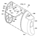
- a canister 902 similar to canister 102 ( FIG. 3 ) or canister 720 ( FIG. 7 ) includes a canister housing 943 having a basin portion 945 and a lid portion 946.
- the lid portion 946 may be formed by an exit wall 942 that is substantially planar and is capable of mating with the basin portion 945 to form a liquid collection chamber.
- the basin portion 945 is formed from a basin wall 950 that includes curved contours to create a crescent shape
- the basin portion 945 and lid portion 946 may instead form a canister that is cylindrical, cubical, spherical, rectangular cubical, or any other shape.
- the canister 902 may not include separate basin and lip portions, but rather may be formed from a substantially unitary housing.
- the liquid-collection chamber may be defined by a single wall.
- the liquid-collection chamber may be formed by a plurality of walls.
- canister 902 includes an inlet 998 that is configured to be fluidly connected to a conduit, and a canister outlet 920 that is fluidly connected to a reduced pressure source.
- a substantially planar liquid-air separator 960 is operatively associated with the outlet 920 of the canister 902 to prevent liquid from exiting the canister 902 through the canister outlet 920.
- the outlet 920 is positioned in the exit wall 942, and the substantially planar liquid-air separator 960 is positioned adjacent to the outlet and secured to the exit wall 942.
- the substantially planar liquid-air separator 960 prevents liquids that that are drawn into the canister 902 from exiting the canister 902 through the outlet 920 and contaminating the reduced pressure source.
- the substantially planar liquid-air separator 960 may be a hydrophobic or oleophobic filter as described previously with reference to liquid-air separator 160.
- the canister 902 includes a dividing member 962 that forms a conduit that allows gaseous communication between the liquid collection chamber and the canister outlet 920 for maintaining reduced pressure in the liquid collection chamber while substantially preventing liquid communication.
- the dividing member 962 includes a wall 964 or membrane that defines a gas-communication pathway or space similar to that described previously with reference to the elongated member 162 illustrated in FIGS. 4A and 4B .
- the wall 964 of the dividing member 962 and the dividing member 962 itself may include the same flexible, or alternatively, rigid characteristics of the elongated member 162.
- At least a portion of the wall 964 is formed from a material that allows gaseous communication between the gas-communication space of the dividing member 962 and the liquid collection chamber of the canister 902.
- the wall 964 or membrane may be formed from a unitary piece of material, or from two or more pieces of material that are welded, bonded, or otherwise attached together.
- the gas-communication space may include a biasing material similar to that previously described with reference to elongated member 162.
- the shape of the dividing member 962 is such that it closely matches an interior profile of the liquid collection chamber of the canister 902, and the dividing member may include a width, W, and a depth, D, that is substantially equal to a corresponding width and depth of the canister housing 943.
- This particular shaping and sizing of the dividing member 962 is such that the dividing member 962 substantially divides the liquid collection chamber of the canister housing 943 into first and second chambers or spaces. In the embodiment illustrated in FIG. 9 , the division of the liquid collection chamber would result in an upper chamber positioned above the dividing member 962 and a lower chamber below the dividing member 962.
- the dividing member 962 may serve to prevent excessive liquid movement or sloshing within the liquid collection chamber since the liquid collection chamber is substantially divided.
- the dividing member 962 may include at least one aperture 980 through the wall of the dividing member 962 to allow fluid communication between the upper chamber and the lower chamber of the liquid collection chamber. The placement of the apertures 980 in the dividing member 962 still maintains the sealed integrity of the gas-communication space within the dividing member 962 such that liquid is not able to enter the gas-communication space.
- the dividing member 962 is connected to the substantially planar liquid-air separator 960.
- the dividing member 962 may be welded to the liquid-air separator 960.
- the dividing member 962 may be connected to the substantially planar liquid-air separator 960 using an adhesive material or by any other suitable means.
- the substantially planar liquid-air separator 960 and the dividing member 962 are not separate components, but rather may be manufactured as a substantially unitary liquid-air separator. When coupled, the substantially planar liquid-air separator 960 and the dividing member 962 serve the same liquid-air-separation purpose of allowing air to move from the canister.
- a substantially planar liquid-air separator 960 may not be used, and the dividing member 962 may be directly connected to the outlet 920 of the canister 902 such that the gas-communication space is in fluid communication with the outlet of the canister 902.
- the dividing member 962 may be connected to the canister 902 at other locations around the perimeter of the dividing member 962.
- the dividing member 902 may be connected at each of four corners 986 to one or more walls of the canister 902. This supplemental attachment of the dividing member 962 to the canister 902 may serve to increase the ability of the dividing member 962 to maintain the divided nature of the liquid collection chamber.
- the dividing member 962 may not be attached to the canister 902 at locations other than the outlet of the canister 902.
- each of the filters and elongated elements described herein may be varied in size or shape to better accommodate a canister of a particular size or shape.
- filter chambers While some of the filters presented herein have been described as having a single interior space or chamber, the number of filter chambers is not limited. Multiple filter chambers that are either independently or jointly connected to the canister outlet or multiple canister outlets may be employed, again depending at least partially upon the size and shape of the canister. Similarly, multiple filter elements may be used to increase the time that the filter maintains gas transmission during liquid collection activities.
- the filters and liquid-collection canisters described herein may be used as part of a process or method for retrofitting an existing wound fluid collection canister design or a new wound collection canister design to allow collection of wound fluid in multiple orientations of the wound fluid collection canister.
- the method includes fluidly connecting an elongated member to an outlet of the wound fluid collection canister. At least a portion of the elongated member extends into a liquid collection area of the wound fluid collection canister.
- the method further includes allowing gas exchange between an inner space of the elongated member and the liquid collection area; and substantially preventing liquid exchange between the inner space and the liquid collection area.
- the method may further include undulating, shaping, positioning, and/or manufacturing the portion of the conduit extending into the liquid collection area of the wound fluid collection canister such that gas exchange between the inner portion of the conduit and the liquid collection area is optimally maintained.
Landscapes
- Health & Medical Sciences (AREA)
- Heart & Thoracic Surgery (AREA)
- Vascular Medicine (AREA)
- Engineering & Computer Science (AREA)
- Anesthesiology (AREA)
- Biomedical Technology (AREA)
- Hematology (AREA)
- Life Sciences & Earth Sciences (AREA)
- Animal Behavior & Ethology (AREA)
- General Health & Medical Sciences (AREA)
- Public Health (AREA)
- Veterinary Medicine (AREA)
- Media Introduction/Drainage Providing Device (AREA)
- External Artificial Organs (AREA)
Abstract
Description
- This application claims the benefit of
U.S. Provisional Application No. 61/374,995, filed August 18, 2010 - The present invention relates generally to reduced pressure treatment systems and more particularly to a reduced-pressure, liquid-collection canister having a filter that allows operation of the canister in multiple orientations.
- Clinical studies and practice have shown that providing a reduced pressure in proximity to a tissue site augments and accelerates the growth of new tissue at the tissue site. The applications of this phenomenon are numerous, but one particular application of reduced pressure involves treating wounds. This treatment (frequently referred to in the medical community as "negative pressure wound therapy," "reduced pressure therapy," or "vacuum therapy") provides a number of benefits, including migration of epithelial and subcutaneous tissues cells, improved blood flow, and micro-deformation of tissue at the wound site. Together these benefits result in increased development of granulation tissue and faster healing times. Typically, reduced pressure is applied by a reduced pressure source to tissue through a porous pad or other manifold device. In many instances, wound exudate and other liquids from the tissue site are collected within a canister to prevent the liquids from reaching the reduced pressure source.
- The problems presented by existing reduced pressure systems and liquid collection canisters are solved by the systems and methods of the illustrative embodiments described herein. A reduced pressure treatment system for applying reduced pressure treatment to a tissue site includes a reduced pressure source, a liquid-collection canister, and a manifold positioned at the tissue site and in fluid communication with the liquid-collection canister. In one embodiment, the liquid-collection canister includes at least one canister wall defining a first space configured to collect liquid from the tissue site. A canister outlet is configured to allow communication between the reduced pressure source and the first space. A substantially planar, liquid-air separator is disposed adjacent the canister outlet to prevent the liquid from exiting the first space through the canister outlet. An elongated member is connected to the liquid-air separator and extends away from the liquid-air separator into the first space. The elongated member has a membrane defining a second space along at least a portion of a length of the elongated member, and at least a portion of the membrane allows gaseous communication between the first space and the second space.
- In another embodiment, an apparatus for use in a multi-orientation liquid collection canister to collect liquid from a tissue site is provided. The apparatus includes an elongated member configured for fluid connection to an outlet of the liquid collection canister. The elongated member having a membrane defining a space along at least a portion of a length of the elongated member, and at least a portion of the membrane allows gaseous communication, but substantially prevents liquid communication through the at least a portion of the membrane.
- In yet another embodiment, a reduced pressure treatment system for applying reduced pressure treatment to a tissue site is provided. The system includes a reduced pressure source, a liquid-collection canister, and a manifold positioned at the tissue site and in fluid communication with the liquid-collection canister. The liquid-collection canister includes a chamber configured to collect liquid from the tissue site. A canister outlet is in fluid communication with the reduced pressure source. The liquid-collection canister further includes a flexible member having a gas communication pathway at least partially defined by a flexible membrane. The flexible member is positioned in the chamber such that the gas communication pathway is in fluid communication with the canister outlet and at least a portion of the flexible membrane is gas permeable and substantially liquid impermeable.
- Still, in another embodiment, a liquid-collection canister for collecting liquid from a tissue site is provided. The liquid-collection canister includes a chamber configured to collect liquid from the tissue site. A canister outlet is in fluid communication with the reduced pressure source. The liquid-collection canister further includes a flexible member having a gas communication pathway at least partially defined by a flexible membrane. The flexible member is positioned in the chamber such that the gas communication pathway is in fluid communication with the canister outlet and at least a portion of the flexible membrane is gas permeable and substantially liquid impermeable.
- In another embodiment, an apparatus is provided for use in a multi-orientation liquid collection canister to collect liquid from a tissue site to which reduced pressure treatment is applied. The apparatus includes a flexible member configured for fluid connection to an outlet of the liquid-collection canister. The flexible member having a gas communication pathway at least partially defined by a flexible membrane. The gas communication pathway is adapted to be positioned in fluid communication with the canister outlet and at least a portion of the flexible membrane is gas-permeable and substantially liquid impermeable.
- In yet another embodiment, a reduced pressure treatment system for applying reduced pressure treatment to a tissue site is provided. The system includes a reduced pressure source, a liquid-collection canister, and a manifold positioned at the tissue site and in fluid communication with the liquid-collection canister. The liquid-collection canister includes at least one canister wall defining a chamber configured to collect liquid from the tissue site. A canister outlet is in fluid communication with the reduced pressure source. A conduit is positioned in the chamber. The conduit has a conduit wall forming a gas communication lumen. The gas-communication lumen is fluidly connected to the canister outlet. A liquid-air separator is operably associated with the conduit to allow gas communication, but substantially prevents liquid communication between the chamber and the gas-communication lumen.
- In still another embodiment, an apparatus is provided for use in a multi-orientation liquid collection canister to collect liquid from a tissue site to which reduced pressure treatment is applied. The apparatus includes a conduit adapted to fluidly connect to an outlet of the liquid-collection canister. The conduit having a gas-communication lumen at least partially defined by a conduit wall. A liquid-air separator is operably associated with the conduit to allow gas-communication, but substantially prevents liquid communication between the gas-communication lumen and an area surrounding the conduit.
- In still another embodiment, a method is provided for retrofitting a wound fluid collection canister to allow collection of wound fluid in multiple orientations of the wound fluid collection canister. The method includes fluidly connecting an elongated member to an outlet of the wound fluid collection canister. At least a portion of the elongated member extends into a liquid collection area of the wound fluid collection canister. The method further includes allowing gas exchange between an inner space of the elongated member and the liquid collection area; and substantially preventing liquid exchange between the inner space and the liquid collection area.
- Other objects, features, and advantages of the illustrative embodiments will become apparent with reference to the drawings and detailed description that follow.
-
-
FIG. 1 illustrates a perspective view of a reduced pressure treatment system having a reduced pressure treatment unit and a multi-orientation, liquid-collection canister according to an illustrative embodiment; -
FIG. 2 illustrates an exploded perspective view of the liquid-collection canister ofFIG. 1 and filter elements associated with the liquid-collection canister according to an illustrative embodiment; -
FIG. 3 illustrates a perspective view of the filter element connected to a base of the liquid-collection canister ofFIG. 2 ; -
FIG. 4A illustrates a cross-sectional view of the filter element ofFIG. 3 taken at 4-4; -
FIG. 4B illustrates a cross-sectional view of a filter element according to an illustrative embodiment, the cross-section view similar to that ofFIG. 4A ; -
FIGS. 5A-5D illustrates different configurations of a filter element positioned in the liquid-collection canister ofFIG. 2 according to an illustrative embodiment; -
FIGS. 6A-6C illustrates different orientations of a liquid-collection canister having the filter configuration illustrated inFIG. 5B ; -
FIG. 7 illustrates a liquid-collection canister having a barb connector for connecting a filter element according to an illustrative embodiment; -
FIG. 8 illustrates a cross-sectional side view of the filter element and barb connector ofFIG. 7 according to an illustrative embodiment; and -
FIG. 9 illustrates an exploded perspective view of a liquid-collection canister according to an illustrative embodiment. - In the following detailed description of several illustrative embodiments, reference is made to the accompanying drawings that form a part hereof, and in which is shown by way of illustration specific preferred embodiments in which the invention may be practiced. These embodiments are described in sufficient detail to enable those skilled in the art to practice the invention, and it is understood that other embodiments may be utilized and that logical structural, mechanical, electrical, and chemical changes may be made without departing from the spirit or scope of the invention. To avoid detail not necessary to enable those skilled in the art to practice the embodiments described herein, the description may omit certain information known to those skilled in the art. The following detailed description is, therefore, not to be taken in a limiting sense, and the scope of the illustrative embodiments are defined only by the appended claims.
- The term "reduced pressure" as used herein generally refers to a pressure less than the ambient pressure at a tissue site that is being subjected to treatment. In most cases, this reduced pressure will be less than the atmospheric pressure at which the patient is located. Alternatively, the reduced pressure may be less than a hydrostatic pressure associated with tissue at the tissue site. Although the terms "vacuum" and "negative pressure" may be used to describe the pressure applied to the tissue site, the actual pressure reduction applied to the tissue site may be significantly less than the pressure reduction normally associated with a complete vacuum. Reduced pressure may initially generate fluid flow in the area of the tissue site. As the hydrostatic pressure around the tissue site approaches the desired reduced pressure, the flow may subside, and the reduced pressure is then maintained. Unless otherwise indicated, values of pressure stated herein are gauge pressures. Similarly, references to increases in reduced pressure typically refer to a decrease in absolute pressure, while decreases in reduced pressure typically refer to an increase in absolute pressure.
- The term "tissue site" as used herein refers to a wound or defect located on or within any tissue, including but not limited to, bone tissue, adipose tissue, muscle tissue, neural tissue, dermal tissue, vascular tissue, connective tissue, cartilage, tendons, or ligaments. The term "tissue site" may further refer to areas of any tissue that are not necessarily wounded or defective, but are instead areas in which it is desired to add or promote the growth of additional tissue. For example, reduced pressure tissue treatment may be used in certain tissue areas to grow additional tissue that may be harvested and transplanted to another tissue location.
- Referring to
FIG. 1 , a reducedpressure treatment system 100 for applying a reduced pressure to atissue site 101 of a patient according to an illustrative embodiment includes acanister 102 in fluid communication with a reducedpressure source 108 and a reduced pressure dressing 112 that is positioned at thetissue site 101. The reduced pressure dressing 112 is fluidly connected to aninlet 103 of thecanister 102 by aconduit 120. Theconduit 120 may fluidly communicate with the reduced pressure dressing 112 through atubing adapter 124. - In at least one embodiment described herein, the
canister 102 used to collect exudate or other fluids from thetissue site 101 is configured to allow thecanister 102 to operate in multiple orientations even as thecanister 102 begins to fill with liquid. Thecanister 102 preferably includes a protected gas communication pathway, or dry space, that allows continued gas communication with aliquid collection chamber 104 of thecanister 102 as exudate and other liquids collect within theliquid collection chamber 104. The path of fluid communication in the reducedpressure treatment system 100 is as follows. Reduced pressure is supplied to the gas communication pathway of thecanister 102 by the reducedpressure source 108. Typically this occurs by the reducedpressure source 108 drawing gaseous fluids, such as air, from the gas communication pathway. As the pressure within the gas communication pathway falls, gas flows from theliquid collection chamber 104 of thecanister 102 to the gas communication pathway, thus resulting in a drop in pressure within theliquid collection chamber 104. Liquid is prevented from flowing into the gas communication pathway by a hydrophobic element, an oleophobic element, or some other type of liquid-blocking membrane, liquid-air separator, or other device. The reduced pressure within theliquid collection chamber 104 is transmitted to the dressing 112 at thetissue site 101, which allows fluids (both gases and liquids) to flow from thetissue site 101 to theliquid collection chamber 104. The liquid collects within theliquid collection chamber 104. In some embodiments, multiple fluid communication ports between theliquid collection chamber 104 and the gas communication pathway allow continued gaseous communication between theliquid collection chamber 104 and the gas communication pathway even as theliquid collection chamber 104 fills with liquids and blocks some of these communication ports. This configuration permits continued supply of reduced pressure to theliquid collection chamber 104 until the liquid collection canister is almost completely full of liquid. As an alternative to the multiple ports, a large common port may be provided so that only a portion of the port is covered or blocked by liquid as thecanister 102 fills. - In the embodiment illustrated in
FIG. 1 , the reducedpressure source 108 is an electrically-driven vacuum pump. In another implementation, the reducedpressure source 108 may instead be a manually-actuated or manually-charged pump that does not require electrical power. The reducedpressure source 108 instead may be any other type of reduced pressure pump, or alternatively a wall suction port such as those available in hospitals and other medical facilities. The reducedpressure source 108 may be housed within or used in conjunction with a reducedpressure treatment unit 140, which may also contain sensors, processing units, alarm indicators, memory, databases, software, display units, anduser interfaces 110 that further facilitate the application of reduced pressure treatment to thetissue site 101. In one example, a sensor or switch (not shown) may be disposed at or near the reducedpressure source 108 to determine a source pressure generated by the reducedpressure source 108. The sensor may communicate with a processing unit that monitors and controls the reduced pressure that is delivered by the reducedpressure source 108. - The reduced pressure dressing 112 includes a
distribution manifold 144 adapted to be positioned at thetissue site 101, and acover 148, or drape, that is positioned over thedistribution manifold 144 to maintain reduced pressure beneath thecover 148 at thetissue site 101. Thecover 148 may extend beyond a perimeter of thetissue site 101 and may include an adhesive or bonding agent on thecover 148 to secure thecover 148 to tissue adjacent thetissue site 101. In one embodiment, the adhesive disposed oncover 148 may be used to seal between the tissue and thecover 148 to prevent leakage of reduced pressure from thetissue site 101. In another embodiment, a seal layer (not shown) such as, for example, a hydrogel or other material may be disposed between thecover 148 and the tissue to augment or substitute for the sealing properties of the adhesive. - The
distribution manifold 144 of the reduced pressure dressing 112 is adapted to contact thetissue site 101. Thedistribution manifold 144 may be partially or fully in contact with thetissue site 101 being treated by the reduced pressure dressing 112. When thetissue site 101 is a wound, thedistribution manifold 144 may partially or fully fill the wound. - The
distribution manifold 144 may be any size, shape, or thickness depending on a variety of factors, such as the type of treatment being implemented or the nature and size of thetissue site 101. For example, the size and shape of thedistribution manifold 144 may be customized by a user to cover a particular portion of thetissue site 101, or to fill or partially fill thetissue site 101. Thedistribution manifold 144 may have, for example, a square shape, or may be shaped as a circle, oval, polygon, an irregular shape, or any other shape. - In one illustrative embodiment, the
distribution manifold 144 is a foam material that distributes reduced pressure to thetissue site 101 when thedistribution manifold 144 is in contact with or near thetissue site 101. The foam material may be either hydrophobic or hydrophilic. In one non-limiting example, thedistribution manifold 144 is an open-cell, reticulated polyurethane foam such as GranuFoam® dressing available from Kinetic Concepts, Inc. of San Antonio, Texas. - In the example in which the
distribution manifold 144 is made from a hydrophilic material, thedistribution manifold 144 also functions to wick fluid away from thetissue site 101, while continuing to provide reduced pressure to thetissue site 101 as a manifold. The wicking properties of thedistribution manifold 144 draw fluid away from thetissue site 101 by capillary flow or other wicking mechanisms. An example of a hydrophilic foam is a polyvinyl alcohol, open-cell foam such as V.A.C. WhiteFoam® dressing available from Kinetic Concepts, Inc. of San Antonio, Texas. Other hydrophilic foams may include those made from polyether. Other foams that may exhibit hydrophilic characteristics include hydrophobic foams that have been treated (including plasma treatment) or coated to provide hydrophilicity. In still another embodiment, thedistribution manifold 144 may be a non-woven material such as Libeltex™ TDL2, manufactured by Libeltex Group. - The
distribution manifold 144 may further promote granulation at thetissue site 101 when a reduced pressure is applied through the reduced pressure dressing 112. For example, any or all of the surfaces of thedistribution manifold 144 may have an uneven, coarse, or jagged profile that causes microstrains and stresses at thetissue site 101 when reduced pressure is applied through thedistribution manifold 144. These microstrains and stresses have been shown to increase new tissue growth. - In one embodiment, the
distribution manifold 144 may be constructed from bioresorbable materials that do not have to be removed from a patient's body following use of the reduced pressure dressing 112. Suitable bioresorbable materials may include, without limitation, a polymeric blend of polylactic acid (PLA) and polyglycolic acid (PGA). The polymeric blend may also include without limitation polycarbonates, polyfumarates, and capralactones. Thedistribution manifold 144 may further serve as a scaffold for new cell-growth, or a scaffold material may be used in conjunction with thedistribution manifold 144 to promote cell-growth. A scaffold is a substance or structure used to enhance or promote the growth of cells or formation of tissue, such as a three-dimensional porous structure that provides a template for cell growth. Illustrative examples of scaffold materials include calcium phosphate, collagen, PLA/PGA, coral hydroxy apatites, carbonates, or processed allograft materials. - Referring now to
FIGS. 1 and2 , thecanister 102 includes acanister housing 143 having abasin portion 145 and alid portion 146. Thelid portion 146 may be formed by anexit wall 142 that is substantially planar and is capable of mating with thebasin portion 145 to form theliquid collection chamber 104. While thebasin portion 145 is formed from abasin wall 150 that includes curved contours to create a crescent shape, thebasin portion 145 andlid portion 146 may instead form a canister that is cylindrical, cubical, spherical, rectangular cubical, or any other shape. It should also be noted that thecanister 102 may not include separate basin and lid portions, but rather may be formed from a substantially unitary housing. In such an embodiment, the liquid-collection chamber 104 may be defined by a single wall. Alternatively, the liquid-collection chamber 104 may be formed by a plurality of walls. - The
canister 102 includes theinlet 103 that is fluidly connected to theconduit 120, acanister outlet 156 that is fluidly connected to the reducedpressure source 108, and a substantially planar liquid-air separator 160 that is operatively associated with theoutlet 156 to prevent liquid from exiting thecanister 102 through thecanister outlet 156. Theinlet 103 may be positioned on awall 178 disposed in a recessed region of thebasin portion 145. In one embodiment, theoutlet 156 is positioned in theexit wall 142, and the substantially planar liquid-air separator 160 is positioned adjacent to theoutlet 156 and secured to theexit wall 142. In some embodiments, theexit wall 142 may include a recessedregion 158 that aids in providing a secure connection for the liquid-air separator 160. Theoutlet 156 allows fluid communication between thecanister 102 and the reducedpressure source 108 such that a reduced pressure is capable of being maintained within thecanister 102. This reduced pressure is capable of being transmitted to the tissue site through theinlet 103, theconduit 120, thetubing adapter 124, and thedistribution manifold 144. The reduced pressure draws exudate and other fluids from thetissue site 101 into thecanister 102. The substantially planar liquid-air separator 160 prevents liquids that that are drawn into thecanister 102 from exiting thecanister 102 through theoutlet 156 and contaminating the reducedpressure source 108. - In an illustrative embodiment, the substantially planar liquid-
air separator 160 may be a hydrophobic or oleophobic filter that prevents passage of liquids through theoutlet 156. An example of a suitable hydrophobic material includes an expanded PTFE laminate such as a hydrophobic medical membrane manufactured by WL Gore & Associates, Newark, Delaware; the Aspire® ePTFE filter membrane manufactured by General Electric; or any other suitable membrane. In one embodiment, such a laminate may have a 1.0 micron reference pore size on non woven polyester with a thickness range of 0.17mm-0.34mm. The hydrophobic medical membrane may have a minimum air flow of 18 LPM/cm2 @ 1 bar (15 PSI) and a minimum water entry pressure of 1.1 bar (16.0 PSI). An example of a suitable oleophobic material includes an oleophobic expanded PTFE membrane having a 1.0 micron reference pore size on non woven polyester with a thickness range of 0.15mm-0.39mm. The oleophobic membrane may have a minimum air flow of 12 LPM/cm2 @ 1 bar (15 PSI) and a minimum water entry pressure of 0.8 bar (12.0 PSI). Alternatively, the substantially planar liquid-air separator 160 may be a gravity-based barrier system, or a device that includes a hydrophilic surface to encourage condensation or other separation of liquid from a fluid stream when the fluid stream passes over the surface. Other examples of liquid-air separators 160 may include sintered metals, sintered nylons, specialty fiber filters such as those manufactured by Filtrona, plastics that have been plasma treated to cause the surface to be hydrophilic, or any other material or device that is capable of separating liquid from a fluid stream, or that is otherwise capable of substantially preventing the passage of liquid while allowing the passage of gases. - In accordance with one embodiment, the
canister 102 includes anelongated member 162 that forms a conduit that allows gaseous communication between theliquid collection chamber 104 and thecanister outlet 156 for maintaining reduced pressure in theliquid collection chamber 104 while substantially preventing liquid communication. The term "elongated" as used herein generally refers to a portion having notably a longer length than width. Theelongated member 162 may have a membrane or a wall that defines the gaseous communication space. Theelongated member 162 and thus the membrane or wall of the elongated member may be rigid, semi-rigid, rigid-in-sections, and/or flexible. For example, in some embodiments, theelongated member 162 may be pre-shaped such as with a foil or heat-formed plastic sheet to fit thecanister 102 or any other canister design. In other embodiments,elongated member 162 may extend naturally based on an orientation of thecanister 102. The term "flexible" as used herein generally means capable of being bent or shaped. In some embodiments, the shaping of the elongated member may not involve plastic deformation of any components of the elongated member, but in other embodiments, one or more elements of the elongated member may be plastically deformed such that the elongated member retains its shape after being manipulated and positioned within the canister. In some embodiments, the term "flexible" may refer to the ability of the elongated member to conform or be conformed to different shapes or arrangements within the canister without the use of special tools or equipment, such as for example by hand placement. In some embodiments, theelongated member 162 may include one or more portions/segments spaced along the membrane that allow the gaseous communication between theliquid collection chamber 104 and thecanister outlet 156. In other embodiments, the membrane may substantially comprise a material that allows gaseous communication, but substantially prevents liquid communication. - In one embodiment, the
elongated member 162 is connected to the substantially planar liquid-air separator 160 such that fluid communication is provided between theoutlet 156 and the interior space of theelongated member 162. For example, theelongated member 162 may be welded to the liquid-air separator 160. In other embodiments, theelongated member 162 may be connected to the substantially planar liquid-air separator 160 using an adhesive material or by any other suitable means. Alternatively, in some embodiments, the substantially planar liquid-air separator 160 and theelongated member 162 are not separate components, but rather may be manufactured as a substantially unitary liquid-air separator. When coupled, the substantially planar liquid-air separator 160 and theelongated member 162 serve the same liquid-air-separation purpose of allowing air to move from thecanister 102. - In certain embodiments, the
canister 102 may also include an absorbent material for absorbing exudate and other fluids drawn from thetissue site 101. Additionally, thecanister 102 may include a solidification substance such as isolyzer. Isolyzer reacts with a serum, plasma, tissue and organ homogenates, blood, or other water containing infectious liquids to form a solid substance. -
FIG. 3 illustrates an embodiment depicting the liquid-air separator 160 and theelongated member 162 connected to one another and to thelid portion 146 of thecanister 102. The liquid-air separator 160 is substantially planar to thelid portion 146. It should be noted that the shape and size of the liquid-air separator 160 may change depending on the shape and size of thelid portion 146, theoutlet 156, or the recessedregion 158 of thelid portion 146. - In one embodiment, the
elongated member 162 is substantially perpendicular to the substantially planar liquid-air separator 160. However, in other embodiments, theelongated member 162 may be parallel to the substantially planar liquid-air separator 160 or connected at any angle at the point of attachment. Theelongated member 162 extends away from the substantially planar liquid-air separator 160 and into theliquid collection chamber 104 of thecanister 102. Theelongated member 162 may be of varying length and width depending upon the size and configuration thecanister 102. Theelongated member 162 may be comprised of the same material as the liquid-air separator 160, as described above, or may be made of any other material that is capable of substantially preventing the passage of liquid while allowing the passage of gas. However, theelongated member 162 does not allow gaseous communication through portions of theelongated member 162 which are currently covered with liquid. Therefore, in the disclosed embodiments, theelongated member 162 is advantageously positioned, shaped, and/or manufactured to cover multiple planes within theliquid collection chamber 104 so as to enable thecanister 102 to continue to receive reduced pressure from the reducedpressure source 108 in multiple, if not all, orientations of thecanister 102. In addition to operating in multiple orientations, theelongated member 162 also enables continued air flow when there is fluid slosh that temporarily blocks exposed portions of theelongated member 162. - Additionally, in some embodiments, the
elongated member 162 may comprise substantially of a liquid-air separator material. In another embodiment, theelongated member 162 may have one side that is liquid and gas impermeable, while the other side may comprise substantially of a liquid-air separator material. In yet another embodiment, theelongated member 162 may contain optimally placed portions that are liquid-air separators while the remaining portion of theelongated member 162 is liquid and gas impermeable. Still, in another embodiment, theelongated member 162 may include spaced apertures, and each of the apertures may be covered by a liquid-air separator. The above configurations of theelongated member 162 are provided as examples of certain embodiments. However, it should be noted that other embodiments of theelongated member 162 may be alternatively configured as to enable gaseous communication while substantially preventing liquid communication through theelongated member 162. - For example,
FIG. 4A illustrates a cross-sectional view of theelongated member 162 ofFIG. 3 taken along line 4-4 in accordance with an illustrative embodiment. Theelongated member 162 may consist of afirst portion 402 welded or bonded to asecond portion 406. Both thefirst portion 402 and thesecond portion 406 prevents, or substantially prevents, the passage of liquid (e.g., exudate) from theliquid collection chamber 104 into the inner portion, or gas communication pathway, of theelongated member 162. For instance, in one embodiment, thefirst portion 402 and thesecond portion 406 are hydrophobic membranes. Alternatively, thefirst portion 402 and thesecond portion 406 may be any material coated with a hydrophobic material to make them substantially impermeable to liquid. - In addition, at least one of the
first portion 402 and thesecond portion 406 allows gaseous communication between the inner portion, or gas communication pathway, of theelongated member 162 and theliquid collection chamber 104. In one embodiment, at least one of thefirst portion 402 and thesecond portion 406 may be manufactured using polytetrafluoroethylene (PTFE), expanded polytetrafluoroethylene (ePTFE), or other fluoropolymer products. For example, in one embodiment, both thefirst portion 402 and thesecond portion 406 may be made of an ePTFE membrane manufactured by W.L Gore and Associates, Inc. for enabling gaseous communication between the inner portion of theelongated member 162 and theliquid collection chamber 104 while substantially preventing the passage of liquid. Thefirst portion 402 and thesecond portion 406 may be joined by a weld, by an adhesive material, and/or by any other suitable means for providing a leak-free connection. Alternatively, in some embodiments, thefirst portion 402 and thesecond portion 406 may be manufactured as a single unit. For example, in one embodiment, thefirst portion 402 and thesecond portion 406 may be a folded sheet that is joined along a single seam. - In another embodiment, as depicted in
FIG. 4B , either thefirst portion 402 or thesecond portion 406 may be made of a material that prevents both gaseous and liquid communication, while the other of thefirst portion 402 or thesecond portion 406 is made of a material that allows gaseous communication, but substantially prevents liquid communication. Such a configuration may be less expensive than forming the entireelongated member 162 from gas permeable, liquid impermeable material. - Referring still to
FIGS. 3 ,4A, and 4B , theelongated member 162 may include a manifold or a biasingmember 404 disposed within the conduit between thefirst portion 402 and thesecond portion 406 to reduce collapse of theelongated member 162 when exposed to reduced pressure. In one embodiment, the biasingmember 404 may include a plurality of flow channels to manifold gas flow along the length of theelongated member 162. The biasingmember 404 may be made of a non-woven material, such as, but not limited to, Libeltex™ TDL2, manufactured by Libeltex Group. Non woven materials include a range of polyolefin's, polyesters, and acrylics (and blends and laminates) that may be formed by melt blown, air laid, thermo and spun bonded techniques, and include such suppliers as Libeltex, Freudenberg, Buckeye, and Fiberweb. In other embodiments, the biasingmember 404 may be made of a woven material; or Granufoam. Woven or textile material includes polyolefin, polyester, acrylics, polyurethanes, and polyamide based fibers, and blends and co-component fibers. Example manufacturers include DuPont, Eastman, and Atex. The biasing member may be formed from a compressible material, or alternatively from a rigid material such as for example by a lattice structure or other framework that is comprised of metal, plastic or other substantially rigid materials. - In addition, in some embodiments, the
elongated member 162 may include an odor adsorption material (not depicted) within the conduit, such as, but not limited to, activated charcoal. Alternatively, and/or in addition to, an odor adsorption material may be placed between the connection of the substantially planar liquid-air separator 160 and thelid portion 146 of thecanister 102. -
FIGS. 5A-5D illustrates different configurations of theelongated member 162 within thecanister 102 ofFIG. 1 . In the depicted embodiment ofFIG. 5A , thecanister 102 is oriented such that gravity is asserted in the direction as indicted byarrow 500A.FIG. 5A illustrates thebasin portion 145 connected to thelid portion 146 of the reducedpressure treatment unit 140 to form theliquid collection chamber 104. The substantially planar liquid-air separator 160 is connected to the recessedregion 158 of thebasin portion 145 to receive reduced pressure from the reducedpressure source 108 through thecanister outlet 156. In one embodiment, theelongated member 162 is allowed to extend naturally into theliquid collection chamber 104 based on the direction of gravity. However, it should be noted that in some embodiments, theelongated member 162 may be formed, positioned, or manufactured, as to maintain the depicted shape no matter how thecanister 102 is oriented. - As
liquid 502 is collected in theliquid collection chamber 104, the portion of theelongated member 162 covered by the liquid 502 becomes blocked and does not allow gaseous communication between the inner space of theelongated member 162 and theliquid collection chamber 104. However, the remaining portion of theelongated member 162 , or portions thereof, not covered by the liquid 502 enables gaseous communication between the inner space of theelongated member 162 and theliquid collection chamber 104 for providing reduced pressure from the reducedpressure source 108. As shown inFIG. 5A , under this orientation of thecanister 102 and configuration of theelongated member 162, theliquid collection chamber 104 would continue to receive reduced pressure until theliquid collection chamber 104 is substantially full of liquid. -
FIGS. 5B-5D illustrates other embodiments in which theelongated member 162 is positioned, shaped, or manufactured in a particular shape as to optimally fill theliquid collection chamber 104 in substantially any orientation of thecanister 102 while maintaining reduced pressure in theliquid collection chamber 104. For instance,FIG. 5B illustrates an embodiment in which theelongated member 162 is positioned, shaped, or manufactured to extend into theliquid collection chamber 104 in an undulating configuration. As referenced herein, the term undulating refers to a wave-like configuration. InFIG. 5B , thecanister 102 is oriented such that gravity is asserted in the direction as indicated by thearrow 500A (as shown inFIG. 5A ). Therefore, asliquid 502 enters theliquid collection chamber 104, the liquid level would start covering the bottom portions of theelongated member 162 preventing gaseous communication through the covered portions of theelongated member 162. However, the uncovered upper portions of theelongated member 162 would continue to provide reduced pressure to theliquid collection chamber 104. Because theelongated member 162 is configured in such a way that extends substantially the width of theliquid collection chamber 104, theliquid collection chamber 104 continues to receive reduced pressure until theliquid collection chamber 104 is substantially full. - Additionally, because the
elongated member 162 undulates to substantially cover the area of theliquid collection chamber 104, thecanister 102 may be oriented in substantially any direction, and theliquid collection chamber 104 would still be able to receive reduced pressure until thecanister 102 is substantially full. For example,FIGS. 6A-6C illustrates different orientations of thecanister 102 having the filter configuration illustrated inFIG. 5B . As can be seen in the examples illustrated inFIGS. 6A-6C , no matter how thecanister 102 is oriented, at least a portion of theelongated member 162 is not covered by the liquid 502 that allows for gaseous communication. Therefore, using the undulating configuration of theelongated member 162 as depicted inFIGS. 6A-6C , thecanister 102 is able to maintain reduced pressure in theliquid collection chamber 104 until theliquid collection chamber 104 is substantially full. - In addition, referring back to the undulating configuration of
FIG. 5B , theliquid collection chamber 104 would continue to receive reduced pressure until thecanister 102 is substantially full even if only portions (e.g., atlocations elongated member 162 provide gaseous communication, while the remaining portion of theelongated member 162 is both gas and liquid impermeable. -
FIG. 5C illustrates another embodiment in which theelongated member 162 is positioned, shaped, or manufactured within theliquid collection chamber 104 to enable thecanister 102 to fill with liquid in substantially any orientation while maintaining reduced pressure in theliquid collection chamber 104. For instance, in the depicted embodiment ofFIG. 5C , theelongated member 162 is configured in an "L" shape formation that extends substantially the width and length of theliquid collection chamber 104. Again, theliquid collection chamber 104 would continue to receive reduced pressure until thecanister 102 is substantially full even ifonly portions elongated member 162 provide gaseous communication, while the remaining portion of theelongated member 162 is both gas and liquid impermeable. However, it should be noted that theelongated member 162 may comprise substantially of a liquid-air separator material or may include additional portions/segments beyondportions elongated member 162 that provide gaseous communication, while substantially preventing liquid communication. -
FIG. 5D depicts yet another embodiment in which theelongated member 162 is positioned, shaped, or manufactured within theliquid collection chamber 104 to enable thecanister 102 to fill with liquid in substantially any orientation while maintaining reduced pressure in theliquid collection chamber 104. In the depicted embodiment ofFIG. 5D , theelongated member 162 is configured in a "U" shape formation that extends substantially the width and length of theliquid collection chamber 104. The depicted embodiment ofFIG. 5D provides several advantages over the prior art. For instance, the "U" shape formation may provide more stability to theelongated member 162 by enabling attachment of both ends of theelongated member 162 to thelid portion 146 of the reducedpressure treatment unit 140. This may be particularly advantageous in embodiments in which the reducedpressure treatment unit 140 is mobile unit such as when worn or carried by a patient. In addition, in some embodiments, both ends of theelongated member 162 may be attached to dual canister outlets (not shown) for providing reduced pressure to thecanister 102 through multiple outlet ports. - Referring now to
FIGS. 7 and8 , another embodiment of anelongated member 700 is provided. Beginning withFIG. 7 , a generic canister 720 having abarb connector 710 for connecting theelongated member 700 to the canister 720 is illustrated according to an illustrative embodiment. The canister 720 includes abasin portion 722 that forms aliquid collection chamber 740 when connected to acanister wall 724 of the canister 720. Thebasin portion 722 includes an inlet 730 for transferring reduced pressure to a tissue site (not shown) and for receiving fluid from the tissue site. - In a preferred embodiment, the
barb connector 710 may be formed as an integral part of thecanister wall 724. Thebarb connector 710 is not limited to any particular location on thecanister wall 724, and may be of varying size, shape, thickness, and depth depending on the particular design of the canister 720. In addition, in some embodiments, thecanister wall 724 may include multiple barb connectors for connecting one or more of theelongated member 700 to different locations of thecanister wall 724. In one embodiment, thebarb connector 710 forms a hollowgas communication lumen 712 for receiving reduced pressure from the reducedpressure source 108. AlthoughFIGS. 7 and8 illustrate a barb type connector, theelongated member 700 may be coupled to thecanister wall 724 by other means, including using other types of connectors and/or fasteners such as a clamp, adhesively bonding or welding theelongated member 700 to thecanister wall 724, or by any other means for attaching theelongated member 700 to thecanister wall 724. - The
elongated member 700 is completely sealed except at anopen end 713. Theelongated member 700 connects to thebarb connector 710 through theopen end 713 for receiving reduced pressure through thebarb connector 710. Theelongated member 700 forms a conduit that is shaped, positioned, and/or manufactured to extend into the space of theliquid collection chamber 740 so as to provide optimum coverage for providing reduced pressure to theliquid collection chamber 740. - The
elongated member 700 has aconduit wall 702 that forms agas communication lumen 704 for transferring reduced pressure received from the reduced pressure source to theliquid collection chamber 740. Theconduit wall 702 is substantially liquid impermeable. However, at least a portion theconduit wall 702 allows gaseous communication between thegas communication lumen 704 and theliquid collection chamber 740. In some embodiments, substantially the entire portion of theconduit wall 702 may allow gaseous communication between thegas communication lumen 704 and theliquid collection chamber 740, while substantially preventing liquid communication. Theconduit wall 702 may be made of the same or similar material as previously described above with regard to theelongated member 162. For example, theconduit wall 702 may be made using expanded polytetrafluoroethylene (ePTFE) or any other suitable material that enables gaseous communication while substantially preventing liquid exchange. Theconduit wall 702 may be formed as a single unit or by connecting multiple components/structures together using any suitable connection means such as welding or adhesive. The length, width, and thickness of theconduit wall 702 may vary depending on the particular configurations of the canister 720 so as to provide the optimum use of theliquid collection chamber 740 while maintaining reduced pressure. Additionally, theelongated member 700 may be configured within theliquid collection chamber 740 in any configuration as to optimally provide reduced pressure to theliquid collection chamber 740 such as, but not limited to, the configurations illustrated inFIGS. 5A-5D . - In some embodiments, the
gas communication lumen 704 is an empty space in which reduced pressure can flow. In other embodiments, thegas communication lumen 704 may include a biasingmember 706, such as, but not limited to, a non-woven material. The biasingmember 706 may provide structural support to reduce collapse of the conduit wall when thegas communication lumen 704 is exposed to reduced pressure. The biasingmember 706 may include a plurality of flow channels to manifold gas flow along the length of thegas communication lumen 704. In addition, in some embodiments, an odor adsorption material such as activated charcoal may be added to the biasingmember 706 to absorb odor. -
FIG. 8 illustrates a cross sectional side view of theelongated member 700 connected thebarb connector 710 according to an illustrative embodiment. In one embodiment, theelongated member 700 may be attached to thebarb connector 710 simply by pushing thebarb connector 710 into theopen end 713 of theelongated member 700. In some embodiments, the inner portion of theopen end 713 may include integrated grooves orridges 701 for enabling theopen end 713 of theelongated member 700 to securely grip thebarb connector 710. Theopen end 713 may be manufactured to have any particular size, shape, or thickness depending on the size and/or shape of thebarb connector 710 so as to provide a tight leak-free connection. For example, theopen end 713 of theelongated member 700 may be circular, oval, triangular, square, or any other shape that provides an optimal leak-free connection. In some embodiments, an adhesive, weld, clamp, and/or any other material may be applied to the connection to assist in providing a secure leak-free connection between theopen end 713 of theelongated member 700 and thebarb connector 710. - Referring to
FIG. 9 , acanister 902 similar to canister 102 (FIG. 3 ) or canister 720 (FIG. 7 ) includes acanister housing 943 having abasin portion 945 and alid portion 946. Thelid portion 946 may be formed by anexit wall 942 that is substantially planar and is capable of mating with thebasin portion 945 to form a liquid collection chamber. While thebasin portion 945 is formed from abasin wall 950 that includes curved contours to create a crescent shape, thebasin portion 945 andlid portion 946 may instead form a canister that is cylindrical, cubical, spherical, rectangular cubical, or any other shape. It should also be noted that thecanister 902 may not include separate basin and lip portions, but rather may be formed from a substantially unitary housing. In such an embodiment, the liquid-collection chamber may be defined by a single wall. Alternatively, the liquid-collection chamber may be formed by a plurality of walls. - Similar to canister 102 of
FIG. 3 ,canister 902 includes aninlet 998 that is configured to be fluidly connected to a conduit, and acanister outlet 920 that is fluidly connected to a reduced pressure source. A substantially planar liquid-air separator 960 is operatively associated with theoutlet 920 of thecanister 902 to prevent liquid from exiting thecanister 902 through thecanister outlet 920. In one embodiment, theoutlet 920 is positioned in theexit wall 942, and the substantially planar liquid-air separator 960 is positioned adjacent to the outlet and secured to theexit wall 942. The substantially planar liquid-air separator 960 prevents liquids that that are drawn into thecanister 902 from exiting thecanister 902 through theoutlet 920 and contaminating the reduced pressure source. In an illustrative embodiment, the substantially planar liquid-air separator 960 may be a hydrophobic or oleophobic filter as described previously with reference to liquid-air separator 160. - In accordance with one embodiment, the
canister 902 includes a dividingmember 962 that forms a conduit that allows gaseous communication between the liquid collection chamber and thecanister outlet 920 for maintaining reduced pressure in the liquid collection chamber while substantially preventing liquid communication. The dividingmember 962 includes awall 964 or membrane that defines a gas-communication pathway or space similar to that described previously with reference to theelongated member 162 illustrated inFIGS. 4A and 4B . Thewall 964 of the dividingmember 962 and the dividingmember 962 itself may include the same flexible, or alternatively, rigid characteristics of theelongated member 162. At least a portion of thewall 964 is formed from a material that allows gaseous communication between the gas-communication space of the dividingmember 962 and the liquid collection chamber of thecanister 902. Thewall 964 or membrane may be formed from a unitary piece of material, or from two or more pieces of material that are welded, bonded, or otherwise attached together. The gas-communication space may include a biasing material similar to that previously described with reference toelongated member 162. - The shape of the dividing
member 962 is such that it closely matches an interior profile of the liquid collection chamber of thecanister 902, and the dividing member may include a width, W, and a depth, D, that is substantially equal to a corresponding width and depth of thecanister housing 943. This particular shaping and sizing of the dividingmember 962 is such that the dividingmember 962 substantially divides the liquid collection chamber of thecanister housing 943 into first and second chambers or spaces. In the embodiment illustrated inFIG. 9 , the division of the liquid collection chamber would result in an upper chamber positioned above the dividingmember 962 and a lower chamber below the dividingmember 962. - The dividing
member 962 may serve to prevent excessive liquid movement or sloshing within the liquid collection chamber since the liquid collection chamber is substantially divided. The dividingmember 962 may include at least oneaperture 980 through the wall of the dividingmember 962 to allow fluid communication between the upper chamber and the lower chamber of the liquid collection chamber. The placement of theapertures 980 in the dividingmember 962 still maintains the sealed integrity of the gas-communication space within the dividingmember 962 such that liquid is not able to enter the gas-communication space. - The dividing
member 962 is connected to the substantially planar liquid-air separator 960. For example, the dividingmember 962 may be welded to the liquid-air separator 960. In other embodiments, the dividingmember 962 may be connected to the substantially planar liquid-air separator 960 using an adhesive material or by any other suitable means. Alternatively, in some embodiments, the substantially planar liquid-air separator 960 and the dividingmember 962 are not separate components, but rather may be manufactured as a substantially unitary liquid-air separator. When coupled, the substantially planar liquid-air separator 960 and the dividingmember 962 serve the same liquid-air-separation purpose of allowing air to move from the canister. In still other embodiments, a substantially planar liquid-air separator 960 may not be used, and the dividingmember 962 may be directly connected to theoutlet 920 of thecanister 902 such that the gas-communication space is in fluid communication with the outlet of thecanister 902. - Besides the connection of the dividing
member 962 to the liquid-air separator 960 or the outlet of thecanister 902, the dividingmember 962, in any particular embodiment, may be connected to thecanister 902 at other locations around the perimeter of the dividingmember 962. For example, in the embodiment illustrated inFIG. 9 , the dividingmember 902 may be connected at each of fourcorners 986 to one or more walls of thecanister 902. This supplemental attachment of the dividingmember 962 to thecanister 902 may serve to increase the ability of the dividingmember 962 to maintain the divided nature of the liquid collection chamber. In other embodiments, the dividingmember 962 may not be attached to thecanister 902 at locations other than the outlet of thecanister 902. - While only a few canister shapes have been illustrated and described, use of the filters or elongated elements described herein, and the advantages that these filters and elongated elements provide, is not limited to any particular shape of canister. In addition, each of the filters and elongated elements described herein may be varied in size or shape to better accommodate a canister of a particular size or shape.
- While some of the filters presented herein have been described as having a single interior space or chamber, the number of filter chambers is not limited. Multiple filter chambers that are either independently or jointly connected to the canister outlet or multiple canister outlets may be employed, again depending at least partially upon the size and shape of the canister. Similarly, multiple filter elements may be used to increase the time that the filter maintains gas transmission during liquid collection activities.
- The filters and liquid-collection canisters described herein may be used as part of a process or method for retrofitting an existing wound fluid collection canister design or a new wound collection canister design to allow collection of wound fluid in multiple orientations of the wound fluid collection canister. The method includes fluidly connecting an elongated member to an outlet of the wound fluid collection canister. At least a portion of the elongated member extends into a liquid collection area of the wound fluid collection canister. The method further includes allowing gas exchange between an inner space of the elongated member and the liquid collection area; and substantially preventing liquid exchange between the inner space and the liquid collection area. In some embodiments, the method may further include undulating, shaping, positioning, and/or manufacturing the portion of the conduit extending into the liquid collection area of the wound fluid collection canister such that gas exchange between the inner portion of the conduit and the liquid collection area is optimally maintained.
- It should be apparent from the foregoing that an invention having significant advantages has been provided. While the invention is shown in only a few of its forms, it is not just limited but is susceptible to various changes and modifications without departing from the spirit thereof.
- While a number of discrete embodiments have been described, aspects of each embodiment may not be specific to only that embodiment and it is specifically contemplated that features of embodiments may be combined with features of other embodiments.
- Aspects of the invention are disclosed in the following numbered clauses:
- Clause 1. A reduced pressure treatment system for applying reduced pressure treatment to a tissue site, the system comprising:
- a reduced pressure source; and
- a liquid-collection canister comprising:
- a canister housing defining a first space configured to collect liquid from the tissue site;
- a canister outlet configured to allow fluid communication between the reduced pressure source and the first space;
- a liquid-air separator disposed adjacent the canister outlet to prevent the liquid from exiting the first space through the canister outlet;
- an elongated member connected to the liquid-air separator and extending away from the liquid-air separator into the first space, the elongated member having a wall defining a second space, at least a portion of the wall allowing gaseous communication between the first space and the second space; and
- a biasing member disposed in the second space to reduce collapse of the membrane into the second space when the second space is exposed to reduced pressure.
- Clause 2. The reduced pressure treatment system of Clause 1 further comprising a manifold positioned at the tissue site and in fluid communication with the canister.
- Clause 3. The reduced pressure treatment system of Clause 1, wherein the elongated member is substantially perpendicular to the liquid-air separator.
-
Clause 4. The reduced pressure treatment system of Clause 1, wherein the elongated member and the substantially planar, liquid-air separator is a single unit. - Clause 5. The reduced pressure treatment system of Clause 1, wherein the elongated member is welded to the liquid-air separator.
- Clause 6. The reduced pressure treatment system of Clause I, wherein the elongated member is adhesively bonded to the liquid-air separator.
- Clause 7. The reduced pressure treatment system of Clause I, wherein the biasing member is a compressible material.
- Clause 8. The reduced pressure treatment system of Clause 7, wherein the biasing member is made of a nonwoven material.
- Clause 9. The reduced pressure treatment system of Clause 7, wherein the biasing member is made of a woven material.
- Clause 10. The reduced pressure treatment system of Clause 7, wherein the biasing member includes a plurality of flow channels to manifold gas flow.
- Clause 11. The reduced pressure treatment system of Clause 1, wherein the wall comprises expanded polytetrafluoroethylene (ePTFE).
- Clause 12. The reduced pressure treatment system of Clause 1, wherein substantially the entire wall is comprised of a material that allows gaseous communication but substantially prevents liquid communication.
- Clause 13. The reduced pressure treatment system of Clause 1, wherein the wall includes a first portion welded or bonded to a second portion and at least one of the first and second portions includes one or more liquid-air separators.
- Clause 14. The reduced pressure treatment system of Clause 1, wherein the elongated member includes activated charcoal for odor adsorption.
- Clause 15. The reduced pressure treatment system of Clause 1, wherein the elongated member extends into the first space in an undulating configuration.
- Clause 16. The reduced pressure treatment system of Clause 1, wherein the elongated member extends into the first space such that the elongated member forms a first substantially planar portion and a second substantially planar portion.
- Clause 17. The reduced pressure treatment system of Clause 16, wherein the first substantially planar portion is substantially perpendicular to the second substantially planar portion.
- Clause 18. The reduced pressure treatment system of Clause 16, wherein the first substantially planar portion is substantially parallel to the second substantially planar portion.
- Clause 19. The reduced pressure treatment system of Clause 16, wherein the elongated member further is positioned to form a third substantially planar portion.
- Clause 20. A liquid-collection canister for collecting liquid from a tissue site to which reduced pressure treatment is applied, the liquid-collection canister comprising:
- at least one canister wall defining a first space configured to collect liquid from the tissue site;
- a canister outlet configured to allow communication between the reduced pressure source and the first space; and
- an elongated member fluidly connected to the canister outlet and extending away from the canister outlet into the first space, the elongated member having a membrane defining a second space along at least a portion of a length of the elongated member, at least a portion of the membrane allowing gaseous communication between the first space and the second space.
- Clause 21. The liquid-collection canister of Clause 20 further comprising: a substantially planar, liquid-air separator disposed adjacent the canister outlet to prevent the liquid from exiting the first space through the canister outlet, the elongated member being connected to the substantially planar, liquid-air separator.
- Clause 22. The liquid-collection canister of Clause 20, wherein the elongated member is connected to the canister outlet using a hose barb attachment.
- Clause 23. An apparatus for use in a multi-orientation liquid-collection canister to collect liquid from a tissue site to which reduced pressure treatment is applied, the apparatus comprising:
- an elongated member configured for fluid connection to an outlet of the liquid collection canister, the elongated member having a wall defining a space along at least a portion of a length of the elongated member, at least a portion of the wall allowing gaseous communication but substantially preventing liquid communication with the space through the at least a portion of the wall.
- Clause 24. The apparatus of Clause 23 further comprising a substantially planar, liquid-air separator configured for connection to the outlet of the liquid-collection canister to prevent the liquid from exiting the liquid collection canister, the substantially planar, liquid-air separator configured to substantially cover the outlet and the elongated member being connected to the substantially planar, liquid-air separator.
- Clause 25. The apparatus of Clause 23, wherein the elongated member and the substantially planar, liquid-air separator is a single unit.
- Clause 26. A reduced pressure treatment system for applying reduced pressure treatment to a tissue site, the system comprising:
- a reduced pressure source;
- a liquid-collection canister comprising:
- a chamber configured to collect liquid from the tissue site;
- a canister outlet in fluid communication with the reduced pressure source; and
- a flexible member having a gas communication pathway at least partially defined by a flexible wall, the flexible member being positioned in the chamber such that the gas communication pathway is in fluid communication with the canister outlet, at least a portion of the flexible wall being gas permeable and substantially liquid impermeable.
- Clause 27. The reduced pressure treatment system of Clause 26 further comprising a manifold positioned at the tissue site and in fluid communication with the liquid-collection canister.
- Clause 28. The reduced pressure treatment system of Clause 26, further comprising a substantially planar, liquid-air separator configured for connection to the canister outlet to prevent the liquid from exiting the liquid collection canister, the substantially planar, liquid-air separator configured to substantially cover the canister outlet and the flexible member being connected to the substantially planar, liquid-air separator.
- Clause 29. The reduced pressure treatment system of Clause 28, wherein the flexible member is substantially perpendicular to the liquid-air separator.
- Clause 30. The reduced pressure treatment system of Clause 28, wherein the flexible member is adhesively welded to the liquid-air separator.
- Clause 31. The reduced pressure treatment system of Clause 28, wherein the flexible member is adhesively bonded to the liquid-air separator.
- Clause 32. The reduced pressure treatment system of Clause 30, wherein the flexible member and the substantially planar, liquid-air separator is a single unit.
- Clause 33. The reduced pressure treatment system of Clause 26, wherein the liquid-collection canister further comprises a biasing member disposed in the gas communication pathway to reduce collapse of the flexible wall into the gas communication pathway when the flexible wall is exposed to reduced pressure.
- Clause 34. The reduced pressure treatment system of Clause 33, wherein the biasing member is made of a nonwoven material.
- Clause 35. The reduced pressure treatment system of Clause 33, wherein the biasing member is made of a woven material.
- Clause 36. The reduced pressure treatment system of Clause 33, wherein the biasing member includes a plurality of flow channels to manifold gas flow.
- Clause 37. The reduced pressure treatment system of Clause 26, wherein the wall comprises expanded polytetrafluoroethylene (ePTFE).
- Clause 38. The reduced pressure treatment system of Clause 26, wherein substantially the entire wall is comprised of a material that allows gaseous communication but substantially prevents liquid communication.
- Clause 39. The reduced pressure treatment system of Clause 26, wherein the flexible wall includes a first portion welded or bonded to a second portion and at least one of the first and second portions includes one or more liquid-air separators.
- Clause 40. The reduced pressure treatment system of Clause 26, wherein the flexible member includes activated charcoal for odor adsorption.
- Clause 41. The reduced pressure treatment system of Clause 26, wherein the flexible member is positioned in the chamber in an undulating configuration.
- Clause 42. The reduced pressure treatment system of Clause 26, wherein the flexible member extends into the chamber such that the flexible member forms a first substantially planar portion and a second substantially planar portion.
- Clause 43. The reduced pressure treatment system of Clause 42, wherein the first substantially planar portion is substantially perpendicular to the second substantially planar portion.
- Clause 44. The reduced pressure treatment system of Clause 42, wherein the first substantially planar portion is substantially parallel to the second substantially planar portion.
- Clause 45. The reduced pressure treatment system of Clause 42, wherein the flexible member further is positioned to form a third substantially planar portion.
- Clause 46. A liquid-collection canister for collecting liquid from a tissue site to which reduced pressure treatment is applied, the liquid-collection canister comprising:
- a chamber configured to collect liquid from the tissue site;
- a canister outlet in fluid communication with the reduced pressure source;
- a flexible member having a gas communication pathway at least partially defined by a flexible membrane, the flexible member being positioned in the chamber such that the gas communication pathway is in fluid communication with the canister outlet, at least a portion of the flexible membrane being gas permeable and substantially liquid impermeable.
- Clause 47. The liquid-collection canister of Clause 46, further comprises a substantially planar, liquid-air separator connected to a wall of the multi-orientation liquid-collection canister to substantially cover the canister outlet, the flexible member being connected to the substantially planar, liquid-air separator.
- Clause 48. The liquid-collection canister of Clause 47, wherein the flexible member and the liquid-air separator is a single unit.
- Clause 49. The liquid-collection canister of Clause 47, wherein the flexible member is welded to the liquid-air separator.
- Clause 50. The liquid-collection canister of Clause 47, wherein the flexible member is adhesively bonded to the liquid-air separator.
- Clause 51. The liquid-collection canister of Clause 46, wherein the flexible member is connected to the canister outlet using a hose barb attachment.
- Clause 52. The liquid-collection canister of Clause 46, wherein the flexible member is connected to the canister outlet using a clamp.
- Clause 53. An apparatus for use in a multi-orientation liquid-collection canister to collect liquid from a tissue site to which reduced pressure treatment is applied, the apparatus comprising:
- a flexible member configured for fluid connection to an outlet of the liquid-collection canister, the flexible member having a gas communication pathway at least partially defined by a flexible membrane, the gas communication pathway adapted to be positioned in fluid communication with the canister outlet, at least a portion of the flexible membrane being gas-permeable and substantially liquid impermeable.
- Clause 54. The apparatus of Clause 53 further comprising a substantially planar, liquid-air separator configured to be disposed adjacent the outlet of the multi-orientation liquid- collection canister to prevent the liquid from exiting a collection chamber of the liquid collection canister through the outlet.
- Clause 55. A reduced pressure treatment system for applying reduced pressure treatment to a tissue site, the system comprising:
- a reduced pressure source; and
- a liquid-collection canister comprising:
- at least one canister wall defining a chamber configured to collect liquid from the tissue site;
- a canister outlet in fluid communication with the reduced pressure source;
- a conduit positioned in the chamber, the conduit having a conduit wall forming a gas communication lumen, the gas-communication lumen being fluidly connected to the canister outlet; and
- a liquid-air separator operably associated with the conduit to allow gas communication but to substantially prevent liquid communication between the chamber and the gas-communication lumen.
- Clause 56. The reduced pressure treatment system according to Clause 55 further comprising a manifold positioned at the tissue site and in fluid communication with the chamber of the liquid-collection canister.
- Clause 57. The reduced pressure treatment system according to Clause 55, wherein the conduit is flexible.
- Clause 58. The reduced pressure treatment system of Clause 55, further comprising:
- a substantially planar, hydrophobic filter disposed between the canister outlet and the gas-communication lumen of the conduit.
- Clause 59. The reduced pressure treatment system of Clause 58, wherein the conduit is welded to the hydrophobic filter.
- Clause 60. The reduced pressure treatment system of Clause 58, wherein the conduit is adhesively bonded to the hydrophobic filter.
- Clause 61. The reduced pressure treatment system of Clause 58, wherein the conduit and the hydrophobic filter is a single unit.
- Clause 62. The reduced pressure treatment system of Clause 55, wherein the liquid-collection canister further comprises a biasing member disposed in the conduit to reduce collapse of the conduit when the conduit is exposed to reduced pressure.
- Clause 63. The reduced pressure treatment system of Clause 62, wherein the biasing member is made of a nonwoven material.
- Clause 64. The reduced pressure treatment system of Clause 62, wherein the biasing member is made of a woven material.
- Clause 65. The reduced pressure treatment system of Clause 62, wherein the biasing member includes a plurality of flow channels to manifold gas flow.
- Clause 66. The reduced pressure treatment system of Clause 55, wherein the liquid-air separator is made from expanded polytetrafluoroethylene (ePTFE).
- Clause 67. The reduced pressure treatment system of Clause 55, wherein the liquid-air separator forms at least a portion of the conduit wall.
- Clause 68. The reduced pressure treatment system of Clause 55, wherein the conduit includes at least one aperture through the conduit wall and the liquid-air separator is positioned over the aperture.
- Clause 69. The reduced pressure treatment system of Clause 55, wherein the conduit includes a first portion welded or bonded to a second portion and the liquid-air separator is operably associated with at least one of the first and second portions.
- Clause 70. The reduced pressure treatment system of Clause 55, wherein the conduit includes activated charcoal for odor adsorption.
- Clause 71. The reduced pressure treatment system of Clause 55, wherein the conduit extends into the chamber in an undulating configuration. Clause 72. The reduced pressure treatment system of Clause 55, wherein the conduit extends into the chamber such that the conduit forms a first substantially planar portion and a second substantially planar portion.
- Clause 73. The reduced pressure treatment system of Clause 72, wherein the first substantially planar portion is substantially perpendicular to the second substantially planar portion.
- Clause 74. The reduced pressure treatment system of Clause 72, wherein the first substantially planar portion is substantially parallel to the second substantially planar portion.
- Clause 75. The reduced pressure treatment system of Clause 72, wherein the conduit is positioned to form a third substantially planar portion.
- Clause 76. A liquid-collection canister for collecting liquid from a tissue site to which reduced pressure treatment is applied, the liquid-collection canister comprising:
- at least one canister wall defining a chamber configured to collect liquid from the tissue site;
- a canister outlet in fluid communication with the reduced pressure source;
- a conduit positioned in the chamber, the conduit having a conduit wall forming a gas- communication lumen, the gas-communication lumen being fluidly connected to the canister outlet; and
- a liquid-air separator operably associated with the conduit to allow gas communication but to substantially prevent liquid communication between the chamber and the gas-communication lumen.
- Clause 77. The liquid-collection canister of Clause 76, further comprising a substantially planar, hydrophobic filter disposed between the canister outlet and the gas communication lumen of the conduit.
- Clause 78. The liquid-collection canister of Clause 77, wherein the conduit is welded to the hydrophobic filter.
- Clause 79. The liquid-collection canister of Clause 77, wherein the conduit is adhesively bonded to the hydrophobic filter.
- Clause 80. The liquid-collection canister of Clause 77, wherein the conduit and the hydrophobic filter is a single unit.
- Clause 81. An apparatus for use in a multi-orientation liquid collection canister to collect liquid from a tissue site to which reduced pressure treatment is applied, the apparatus comprising:
- a conduit adapted to fluidly connected to an outlet of the liquid-collection canister, the conduit having a gas-communication lumen at least partially defined by a conduit wall; and
- a liquid-air separator operably associated with the conduit to allow gas-communication but substantially prevent liquid communication between the gas-communication lumen and an area surrounding the conduit.
- Clause 82. The apparatus according to Clause 81 further comprising a substantially planar, liquid-air separator adapted to be positioned over the outlet of the liquid-collection canister, the substantially planar, liquid-air separator connected to the conduit.
- Clause 83. The apparatus according to Clause 81, wherein the conduit wall includes at least one aperture and the liquid-air separator is positioned over the at least one aperture.
- Clause 84. A method for retrofitting a wound fluid collection canister to allow collection of wound fluid in multiple orientations of the wound fluid collection canister, the method comprising:
- fluidly connecting a elongated member to an outlet of the wound fluid collection canister, at least a portion of the elongated member extending into a liquid collection area of the wound fluid collection canister;
- allowing gas exchange between an inner space of the elongated member and the liquid collection area; and
- substantially preventing liquid exchange between the inner space and the liquid collection area.
- Clause 85. The method of Clause 84, further comprising:
- positioning the portion of the elongated member extending into the liquid collection area such that the elongated member lies in at least two planes.
- Clause 86. The method of Clause 85, wherein the at least two planes are substantially perpendicular.
- Clause 87. The method of Clause 84, further comprising:
- positioning the portion of the elongated member extending into the liquid collection area such that the elongated member lies in at least three planes.
- Clause 88. The method of Clause 84, further comprising:
- undulating the portion of the elongated member extending into the liquid collection area.
- Clause 89. The method of Clause 84, wherein fluidly connecting the elongated member to the outlet further comprises:
- connecting the elongated member to a hose barb attachment associated with the outlet.
- Clause 90. The method of Clause 84, wherein fluidly connecting the elongated member to the outlet further comprises:
- connecting the elongated member to a substantially planar, liquid-air separator that covers the outlet.
- Clause 91. The method of Clause 90, wherein the elongated member is welded to the substantially planar, liquid-air separator.
- Clause 92. The method of Clause 90, wherein the elongated member is adhesively bonded to the substantially planar, liquid-air separator.
- Clause 93. The method of Clause 84, wherein the elongated member includes a biasing member disposed in the inner space to reduce collapse of the elongated member when exposed to reduced pressure.
- Clause 94. A reduced pressure treatment system for applying reduced pressure treatment to a tissue site, the system comprising:
- a reduced pressure source; and
- a liquid-collection canister comprising:
- a canister housing defining a first space configured to collect liquid from the tissue site;
- a canister outlet configured to allow fluid communication between the reduced pressure source and the first space; and
- a dividing member having a wall defining a second space, at least a portion of the wall allowing gaseous communication between the first space and the second space, the second space of the dividing member being fluidly connected to the canister outlet; the dividing member having a width and a depth that is substantially equal to a width and depth of the canister housing such that the dividing member divides the first space of the canister housing into first and second chambers, the dividing member having at least one aperture through the wall to allow fluid communication between the first chamber and the second chamber.
- Clause 95. The system of clause 94 further comprising:
- a liquid-air separator disposed adjacent the canister outlet to prevent the liquid from exiting the first space through the canister outlet; and
- wherein the dividing member is connected to the liquid-air separator.
- Clause 96. The system of clause 94, wherein the dividing member includes at least four corners and each corner is connected to a wall of the canister housing.
- Clause 97. The system of clause 94 further comprising:
- a biasing member positioned within the second space to reduced collapse of the wall of the dividing member into the second space when the second space is exposed to reduced pressure.
- Clause 98. The system of clause 94, wherein the wall of the dividing member is flexible.
- Clause 99. The system of clause 94, wherein the dividing member is substantially planar.
-
Clause 100. A liquid-collection canister for collecting liquid from a tissue site to which reduced pressure treatment is applied, the liquid-collection canister comprising:- at least one canister wall defining a first space configured to collect liquid from the tissue site;
- an elongated member defining a second space within the first space, the first space being isolated from the second space by a wall which allows the passage of gas but prevents the passage of liquid between the first and second spaces, and
- a canister outlet through the at least one canister wall in fluid communication with the second space.
-
Clause 101. A liquid-collection canister according toclause 100, wherein at least part of the wall is formed of a liquid-impermeable, gas-permeable, material. -
Clause 102. A liquid-collection canister according toclause 100 orclause 101, further comprising a substantially planar liquid-air separator providing a gas communication path between the canister outlet and the first space. -
Clause 103. A liquid-collection canister according to any ofclauses 100 to 102, further comprising a biasing member within the second space. -
Clause 104. A liquid-collection canister according to any ofclauses 100 to 103, wherein the elongated member is at least partially flexible - Clause 105. A liquid-collection canister according to any of
clauses 100 to 104, wherein liquid- impermeable, gas-permeable, parts of the member's wall are formed of expanded polytetrafluoroethylene (ePTFE). - Clause 106. A liquid-collection canister according to
clause 103, wherein the biasing member comprises a plurality of flow-channels to manifold gas flow. - Clause 107. A liquid-collection canister according to any of
clauses 100 to 106, wherein the elongated member extends into the first space in an undulated configuration. -
Clause 108. A liquid-collection canister according to any ofclauses 100 to 107, wherein the elongated member forms at least two substantially planar portions in the lengthwise direction. - Clause 109. A liquid-collection canister according to any of
clauses 100 to 108, wherein the elongated member is configured to ensure a gas communication pathway exists from the first space to the canister outlet until the canister is substantially filled and with the canister in any orientation. -
Clause 110. A reduced pressure treatment system for applying reduced pressure treatment to a tissue site, the system comprising:- a reduced pressure source; and a liquid-collection canister according to any of
clauses 100 to 109, wherein the reduced pressure source is configured to provide reduced pressure to the canister outlet.
- a reduced pressure source; and a liquid-collection canister according to any of
Claims (15)
- A reduced pressure treatment system for applying reduced pressure treatment to a tissue site, the system comprising:a reduced pressure source;a liquid-collection canister comprising:a chamber configured to collect liquid from the tissue site;a canister outlet in fluid communication with the reduced pressure source; anda conduit having a gas communication pathway at least partially defined by a wall, the conduit being positioned in the chamber such that the gas communication pathway is in fluid communication with the canister outlet, at least a portion of the wall being gas permeable and substantially liquid impermeable.
- The system of Claim 1, further comprising a manifold positioned at the tissue site and in fluid communication with the liquid-collection canister.
- The system of Claim 1, further comprising a substantially planar, liquid-air separator configured for connection to the canister outlet to prevent the liquid from exiting the liquid-collection canister, the substantially planar, liquid-air separator configured to substantially cover the canister outlet and the conduit being connected to the substantially planar, liquid-air separator.
- The system of Claim 3, wherein the conduit is substantially perpendicular to the liquid-air separator.
- The system of Claim 3, wherein the conduit is adhesively bonded to the liquid-air separator.
- The system of Claim 3, wherein the conduit and the substantially planar, liquid-air separator is a single unit.
- The system of Claim 1, wherein the liquid-collection canister further comprises a biasing member disposed in the gas communication pathway to reduce collapse of the wall into the gas communication pathway when the wall is exposed to reduced pressure.
- The system of Claim 7, wherein the biasing member is made of a nonwoven material.
- The system of Claim 7, wherein the biasing member is made of a woven material.
- The system of Claim 7, wherein the biasing member includes a plurality of flow channels to manifold gas flow.
- The system of Claim 1, wherein the wall comprises expanded polytetrafluoroethylene (ePTFE).
- The system of Claim 1, wherein substantially the entire wall is comprised of a material that allows gaseous communication but substantially prevents liquid communication.
- The system of Claim 1, wherein the wall includes a first portion welded or bonded to a second portion and at least one of the first and second portions includes one or more liquid-air separators.
- The system of Claim 1, wherein the conduit is positioned in the chamber in an undulating configuration.
- The system of Claim 1, wherein the conduit extends into the chamber such that the conduit forms a first substantially planar portion and a second substantially planar portion.
Priority Applications (1)
| Application Number | Priority Date | Filing Date | Title |
|---|---|---|---|
| EP19166977.9A EP3524283A1 (en) | 2010-08-18 | 2011-08-16 | Reduced pressure, multi-orientation, liquid collection canister |
Applications Claiming Priority (3)
| Application Number | Priority Date | Filing Date | Title |
|---|---|---|---|
| US37499510P | 2010-08-18 | 2010-08-18 | |
| EP11751734.2A EP2605808B1 (en) | 2010-08-18 | 2011-08-16 | Reduced-pressure, multi-orientation, liquid-collection canister |
| PCT/US2011/047973 WO2012024327A2 (en) | 2010-08-18 | 2011-08-16 | Reduced-pressure, multi-orientation, liquid-collection canister |
Related Parent Applications (1)
| Application Number | Title | Priority Date | Filing Date |
|---|---|---|---|
| EP11751734.2A Division EP2605808B1 (en) | 2010-08-18 | 2011-08-16 | Reduced-pressure, multi-orientation, liquid-collection canister |
Related Child Applications (1)
| Application Number | Title | Priority Date | Filing Date |
|---|---|---|---|
| EP19166977.9A Division EP3524283A1 (en) | 2010-08-18 | 2011-08-16 | Reduced pressure, multi-orientation, liquid collection canister |
Publications (2)
| Publication Number | Publication Date |
|---|---|
| EP3132814A1 true EP3132814A1 (en) | 2017-02-22 |
| EP3132814B1 EP3132814B1 (en) | 2019-05-01 |
Family
ID=44543849
Family Applications (3)
| Application Number | Title | Priority Date | Filing Date |
|---|---|---|---|
| EP19166977.9A Withdrawn EP3524283A1 (en) | 2010-08-18 | 2011-08-16 | Reduced pressure, multi-orientation, liquid collection canister |
| EP16192619.1A Active EP3132814B1 (en) | 2010-08-18 | 2011-08-16 | Reduced-pressure, multi-orientation, liquid-collection canister |
| EP11751734.2A Active EP2605808B1 (en) | 2010-08-18 | 2011-08-16 | Reduced-pressure, multi-orientation, liquid-collection canister |
Family Applications Before (1)
| Application Number | Title | Priority Date | Filing Date |
|---|---|---|---|
| EP19166977.9A Withdrawn EP3524283A1 (en) | 2010-08-18 | 2011-08-16 | Reduced pressure, multi-orientation, liquid collection canister |
Family Applications After (1)
| Application Number | Title | Priority Date | Filing Date |
|---|---|---|---|
| EP11751734.2A Active EP2605808B1 (en) | 2010-08-18 | 2011-08-16 | Reduced-pressure, multi-orientation, liquid-collection canister |
Country Status (8)
| Country | Link |
|---|---|
| US (3) | US9463265B2 (en) |
| EP (3) | EP3524283A1 (en) |
| JP (1) | JP6004443B2 (en) |
| CN (2) | CN103096947B (en) |
| AU (1) | AU2011292096B2 (en) |
| CA (1) | CA2808591C (en) |
| TW (1) | TW201217017A (en) |
| WO (1) | WO2012024327A2 (en) |
Families Citing this family (21)
| Publication number | Priority date | Publication date | Assignee | Title |
|---|---|---|---|---|
| US20110054420A1 (en) * | 2009-08-27 | 2011-03-03 | Christopher Brian Locke | Reduced-pressure wound dressings and systems for re-epithelialization and granulation |
| US8690844B2 (en) * | 2009-08-27 | 2014-04-08 | Kci Licensing, Inc. | Re-epithelialization wound dressings and systems |
| US8403902B2 (en) * | 2010-05-18 | 2013-03-26 | Kci Licensing, Inc. | Reduced-pressure medical systems and methods employing a moisture processing device |
| JP6004443B2 (en) * | 2010-08-18 | 2016-10-05 | ケーシーアイ ライセンシング インコーポレイテッド | Depressurized liquid collection canister in multiple orientations |
| AU2011316599B2 (en) | 2010-10-12 | 2018-09-20 | Smith & Nephew, Inc. | Medical device |
| US8758315B2 (en) * | 2012-02-21 | 2014-06-24 | Kci Licensing, Inc. | Multi-orientation canister for use with a reduced pressure treatment system |
| US9457135B2 (en) * | 2012-12-03 | 2016-10-04 | Devilbiss Healthcare Llc | Suction canister having a replaceable filter cartridge |
| EP3607977A1 (en) * | 2013-01-16 | 2020-02-12 | KCI Licensing, Inc. | Ion exchange enhanced absorbent systems |
| WO2014134219A1 (en) * | 2013-02-26 | 2014-09-04 | Pfm Medical, Inc. | Drainage system for wounds |
| AU2014236701B2 (en) | 2013-03-14 | 2018-07-19 | Smith & Nephew Inc. | Systems and methods for applying reduced pressure therapy |
| US9737649B2 (en) | 2013-03-14 | 2017-08-22 | Smith & Nephew, Inc. | Systems and methods for applying reduced pressure therapy |
| US10155070B2 (en) | 2013-08-13 | 2018-12-18 | Smith & Nephew, Inc. | Systems and methods for applying reduced pressure therapy |
| CA2956572C (en) | 2014-07-31 | 2023-06-27 | Smith & Nephew, Inc. | Systems and methods for applying reduced pressure therapy |
| WO2017187544A1 (en) * | 2016-04-27 | 2017-11-02 | 悠一 佐紺 | Molded-body filter using ptfe film, and disposable bag or container for medical aspirator using said molded-body filter |
| EP3612242A1 (en) | 2017-04-19 | 2020-02-26 | Smith & Nephew, Inc | Negative pressure wound therapy canisters |
| US20220001095A1 (en) * | 2018-11-19 | 2022-01-06 | Kci Licensing, Inc. | System And Apparatus For Preventing Therapy Unit Contamination |
| EP3666301B1 (en) | 2018-12-14 | 2024-02-21 | Mölnlycke Health Care AB | A canister for a mobile negative pressure wound therapy device |
| USD935034S1 (en) | 2020-03-05 | 2021-11-02 | Deroyal Industries, Inc. | Negative pressure wound therapy canister |
| USD935033S1 (en) | 2020-03-05 | 2021-11-02 | Deroyal Industries, Inc. | Negative pressure wound therapy canister |
| USD935035S1 (en) | 2020-03-05 | 2021-11-02 | Deroyal Industries, Inc. | Negative pressure wound therapy canister |
| WO2023079379A1 (en) * | 2021-11-05 | 2023-05-11 | Kci Manufacturing Unlimited Company | Liquid-collection canister with multi-orientation filter |
Citations (3)
| Publication number | Priority date | Publication date | Assignee | Title |
|---|---|---|---|---|
| WO2009016195A2 (en) * | 2007-07-31 | 2009-02-05 | Coloplast A/S | A wound treatment device |
| WO2009149250A1 (en) * | 2008-06-04 | 2009-12-10 | Kci Licensing, Inc. | Reduced-pressure, liquid-collection canister with multi-orientation filter |
| US20100286638A1 (en) * | 2009-05-11 | 2010-11-11 | Tyco Healthcare Group Lp | Orientation Independent Canister for a Negative Pressure Wound Therapy Device |
Family Cites Families (150)
| Publication number | Priority date | Publication date | Assignee | Title |
|---|---|---|---|---|
| US1355846A (en) | 1920-02-06 | 1920-10-19 | David A Rannells | Medical appliance |
| US2547758A (en) | 1949-01-05 | 1951-04-03 | Wilmer B Keeling | Instrument for treating the male urethra |
| US2632443A (en) | 1949-04-18 | 1953-03-24 | Eleanor P Lesher | Surgical dressing |
| GB692578A (en) | 1949-09-13 | 1953-06-10 | Minnesota Mining & Mfg | Improvements in or relating to drape sheets for surgical use |
| US2682873A (en) | 1952-07-30 | 1954-07-06 | Johnson & Johnson | General purpose protective dressing |
| NL189176B (en) | 1956-07-13 | 1900-01-01 | Hisamitsu Pharmaceutical Co | PLASTER BASED ON A SYNTHETIC RUBBER. |
| US2969057A (en) | 1957-11-04 | 1961-01-24 | Brady Co W H | Nematodic swab |
| US3066672A (en) | 1960-09-27 | 1962-12-04 | Jr William H Crosby | Method and apparatus for serial sampling of intestinal juice |
| US3367332A (en) | 1965-08-27 | 1968-02-06 | Gen Electric | Product and process for establishing a sterile area of skin |
| US3520300A (en) | 1967-03-15 | 1970-07-14 | Amp Inc | Surgical sponge and suction device |
| US3568675A (en) | 1968-08-30 | 1971-03-09 | Clyde B Harvey | Fistula and penetrating wound dressing |
| US3682180A (en) | 1970-06-08 | 1972-08-08 | Coilform Co Inc | Drain clip for surgical drain |
| BE789293Q (en) | 1970-12-07 | 1973-01-15 | Parke Davis & Co | MEDICO-SURGICAL DRESSING FOR BURNS AND SIMILAR LESIONS |
| US3826254A (en) | 1973-02-26 | 1974-07-30 | Verco Ind | Needle or catheter retaining appliance |
| DE2527706A1 (en) | 1975-06-21 | 1976-12-30 | Hanfried Dr Med Weigand | DEVICE FOR THE INTRODUCTION OF CONTRAST AGENTS INTO AN ARTIFICIAL INTESTINAL OUTLET |
| US4033345A (en) * | 1975-11-13 | 1977-07-05 | Sorenson Research Co., Inc. | Autologous transfusion filter system and method |
| DE2640413C3 (en) | 1976-09-08 | 1980-03-27 | Richard Wolf Gmbh, 7134 Knittlingen | Catheter monitor |
| NL7710909A (en) | 1976-10-08 | 1978-04-11 | Smith & Nephew | COMPOSITE STRAPS. |
| GB1562244A (en) | 1976-11-11 | 1980-03-05 | Lock P M | Wound dressing materials |
| US4080970A (en) | 1976-11-17 | 1978-03-28 | Miller Thomas J | Post-operative combination dressing and internal drain tube with external shield and tube connector |
| US4139004A (en) | 1977-02-17 | 1979-02-13 | Gonzalez Jr Harry | Bandage apparatus for treating burns |
| US4184510A (en) | 1977-03-15 | 1980-01-22 | Fibra-Sonics, Inc. | Valued device for controlling vacuum in surgery |
| US4275732A (en) * | 1977-08-19 | 1981-06-30 | Gereg Gordon A | Suction canister with membrane shut-off valve |
| US4165748A (en) | 1977-11-07 | 1979-08-28 | Johnson Melissa C | Catheter tube holder |
| US4256109A (en) | 1978-07-10 | 1981-03-17 | Nichols Robert L | Shut off valve for medical suction apparatus |
| SE414994B (en) | 1978-11-28 | 1980-09-01 | Landstingens Inkopscentral | VENKATETERFORBAND |
| BR7908937A (en) | 1978-12-06 | 1981-06-30 | Svedman Paul | DEVICE FOR TREATING FABRICS, FOR EXAMPLE, SKIN |
| US4266545A (en) | 1979-04-06 | 1981-05-12 | Moss James P | Portable suction device for collecting fluids from a closed wound |
| US4284079A (en) | 1979-06-28 | 1981-08-18 | Adair Edwin Lloyd | Method for applying a male incontinence device |
| US4261363A (en) | 1979-11-09 | 1981-04-14 | C. R. Bard, Inc. | Retention clips for body fluid drains |
| US4569348A (en) | 1980-02-22 | 1986-02-11 | Velcro Usa Inc. | Catheter tube holder strap |
| US4480638A (en) | 1980-03-11 | 1984-11-06 | Eduard Schmid | Cushion for holding an element of grafted skin |
| US4297995A (en) | 1980-06-03 | 1981-11-03 | Key Pharmaceuticals, Inc. | Bandage containing attachment post |
| US4333468A (en) | 1980-08-18 | 1982-06-08 | Geist Robert W | Mesentery tube holder apparatus |
| US4465485A (en) | 1981-03-06 | 1984-08-14 | Becton, Dickinson And Company | Suction canister with unitary shut-off valve and filter features |
| US4392853A (en) | 1981-03-16 | 1983-07-12 | Rudolph Muto | Sterile assembly for protecting and fastening an indwelling device |
| US4373519A (en) | 1981-06-26 | 1983-02-15 | Minnesota Mining And Manufacturing Company | Composite wound dressing |
| US4392858A (en) | 1981-07-16 | 1983-07-12 | Sherwood Medical Company | Wound drainage device |
| US4419097A (en) | 1981-07-31 | 1983-12-06 | Rexar Industries, Inc. | Attachment for catheter tube |
| AU550575B2 (en) | 1981-08-07 | 1986-03-27 | Richard Christian Wright | Wound drainage device |
| SE429197B (en) | 1981-10-14 | 1983-08-22 | Frese Nielsen | SAR TREATMENT DEVICE |
| DE3146266A1 (en) | 1981-11-21 | 1983-06-01 | B. Braun Melsungen Ag, 3508 Melsungen | COMBINED DEVICE FOR A MEDICAL SUCTION DRAINAGE |
| US4551139A (en) | 1982-02-08 | 1985-11-05 | Marion Laboratories, Inc. | Method and apparatus for burn wound treatment |
| US4475909A (en) | 1982-05-06 | 1984-10-09 | Eisenberg Melvin I | Male urinary device and method for applying the device |
| EP0100148B1 (en) | 1982-07-06 | 1986-01-08 | Dow Corning Limited | Medical-surgical dressing and a process for the production thereof |
| NZ206837A (en) | 1983-01-27 | 1986-08-08 | Johnson & Johnson Prod Inc | Thin film adhesive dressing:backing material in three sections |
| US4548202A (en) | 1983-06-20 | 1985-10-22 | Ethicon, Inc. | Mesh tissue fasteners |
| US4540412A (en) | 1983-07-14 | 1985-09-10 | The Kendall Company | Device for moist heat therapy |
| US4543100A (en) | 1983-11-01 | 1985-09-24 | Brodsky Stuart A | Catheter and drain tube retainer |
| US4525374A (en) | 1984-02-27 | 1985-06-25 | Manresa, Inc. | Treating hydrophobic filters to render them hydrophilic |
| GB2157958A (en) | 1984-05-03 | 1985-11-06 | Ernest Edward Austen Bedding | Ball game net support |
| US4897081A (en) | 1984-05-25 | 1990-01-30 | Thermedics Inc. | Percutaneous access device |
| US5215522A (en) | 1984-07-23 | 1993-06-01 | Ballard Medical Products | Single use medical aspirating device and method |
| GB8419745D0 (en) | 1984-08-02 | 1984-09-05 | Smith & Nephew Ass | Wound dressing |
| US4872450A (en) | 1984-08-17 | 1989-10-10 | Austad Eric D | Wound dressing and method of forming same |
| US4826494A (en) | 1984-11-09 | 1989-05-02 | Stryker Corporation | Vacuum wound drainage system |
| US4655754A (en) | 1984-11-09 | 1987-04-07 | Stryker Corporation | Vacuum wound drainage system and lipids baffle therefor |
| US4605399A (en) | 1984-12-04 | 1986-08-12 | Complex, Inc. | Transdermal infusion device |
| US5037397A (en) | 1985-05-03 | 1991-08-06 | Medical Distributors, Inc. | Universal clamp |
| US4640688A (en) | 1985-08-23 | 1987-02-03 | Mentor Corporation | Urine collection catheter |
| US4710165A (en) | 1985-09-16 | 1987-12-01 | Mcneil Charles B | Wearable, variable rate suction/collection device |
| US4758220A (en) | 1985-09-26 | 1988-07-19 | Alcon Laboratories, Inc. | Surgical cassette proximity sensing and latching apparatus |
| US4733659A (en) | 1986-01-17 | 1988-03-29 | Seton Company | Foam bandage |
| EP0256060A1 (en) | 1986-01-31 | 1988-02-24 | OSMOND, Roger L. W. | Suction system for wound and gastro-intestinal drainage |
| US4838883A (en) | 1986-03-07 | 1989-06-13 | Nissho Corporation | Urine-collecting device |
| JPS62281965A (en) | 1986-05-29 | 1987-12-07 | テルモ株式会社 | Catheter and catheter fixing member |
| GB8621884D0 (en) | 1986-09-11 | 1986-10-15 | Bard Ltd | Catheter applicator |
| GB2195255B (en) | 1986-09-30 | 1991-05-01 | Vacutec Uk Limited | Apparatus for vacuum treatment of an epidermal surface |
| US4743232A (en) | 1986-10-06 | 1988-05-10 | The Clinipad Corporation | Package assembly for plastic film bandage |
| DE3634569A1 (en) | 1986-10-10 | 1988-04-21 | Sachse Hans E | CONDOM CATHETER, A URINE TUBE CATHETER FOR PREVENTING RISING INFECTIONS |
| JPS63135179A (en) | 1986-11-26 | 1988-06-07 | 立花 俊郎 | Subcataneous drug administration set |
| GB8628564D0 (en) | 1986-11-28 | 1987-01-07 | Smiths Industries Plc | Anti-foaming agent suction apparatus |
| GB8706116D0 (en) | 1987-03-14 | 1987-04-15 | Smith & Nephew Ass | Adhesive dressings |
| US4787888A (en) | 1987-06-01 | 1988-11-29 | University Of Connecticut | Disposable piezoelectric polymer bandage for percutaneous delivery of drugs and method for such percutaneous delivery (a) |
| US4863449A (en) | 1987-07-06 | 1989-09-05 | Hollister Incorporated | Adhesive-lined elastic condom cathether |
| US5176663A (en) | 1987-12-02 | 1993-01-05 | Pal Svedman | Dressing having pad with compressibility limiting elements |
| US4906240A (en) | 1988-02-01 | 1990-03-06 | Matrix Medica, Inc. | Adhesive-faced porous absorbent sheet and method of making same |
| US4985019A (en) | 1988-03-11 | 1991-01-15 | Michelson Gary K | X-ray marker |
| GB8812803D0 (en) | 1988-05-28 | 1988-06-29 | Smiths Industries Plc | Medico-surgical containers |
| US4919654A (en) | 1988-08-03 | 1990-04-24 | Kalt Medical Corporation | IV clamp with membrane |
| US5000741A (en) | 1988-08-22 | 1991-03-19 | Kalt Medical Corporation | Transparent tracheostomy tube dressing |
| DE69017479T2 (en) | 1989-01-16 | 1995-07-13 | Roussel Uclaf | Azabicyclohepten derivatives and their salts, processes for their preparation, their use as medicaments and preparations containing them. |
| GB8906100D0 (en) | 1989-03-16 | 1989-04-26 | Smith & Nephew | Laminates |
| US5261893A (en) | 1989-04-03 | 1993-11-16 | Zamierowski David S | Fastening system and method |
| US4969880A (en) | 1989-04-03 | 1990-11-13 | Zamierowski David S | Wound dressing and treatment method |
| US5100396A (en) | 1989-04-03 | 1992-03-31 | Zamierowski David S | Fluidic connection system and method |
| US5527293A (en) | 1989-04-03 | 1996-06-18 | Kinetic Concepts, Inc. | Fastening system and method |
| US5358494A (en) | 1989-07-11 | 1994-10-25 | Svedman Paul | Irrigation dressing |
| JP2719671B2 (en) | 1989-07-11 | 1998-02-25 | 日本ゼオン株式会社 | Wound dressing |
| US5232453A (en) | 1989-07-14 | 1993-08-03 | E. R. Squibb & Sons, Inc. | Catheter holder |
| GB2235877A (en) | 1989-09-18 | 1991-03-20 | Antonio Talluri | Closed wound suction apparatus |
| US5134994A (en) | 1990-02-12 | 1992-08-04 | Say Sam L | Field aspirator in a soft pack with externally mounted container |
| US5092858A (en) | 1990-03-20 | 1992-03-03 | Becton, Dickinson And Company | Liquid gelling agent distributor device |
| US5149331A (en) | 1991-05-03 | 1992-09-22 | Ariel Ferdman | Method and device for wound closure |
| US5278100A (en) | 1991-11-08 | 1994-01-11 | Micron Technology, Inc. | Chemical vapor deposition technique for depositing titanium silicide on semiconductor wafers |
| US5645081A (en) | 1991-11-14 | 1997-07-08 | Wake Forest University | Method of treating tissue damage and apparatus for same |
| US5636643A (en) | 1991-11-14 | 1997-06-10 | Wake Forest University | Wound treatment employing reduced pressure |
| US5279550A (en) | 1991-12-19 | 1994-01-18 | Gish Biomedical, Inc. | Orthopedic autotransfusion system |
| US5167613A (en) | 1992-03-23 | 1992-12-01 | The Kendall Company | Composite vented wound dressing |
| FR2690617B1 (en) | 1992-04-29 | 1994-06-24 | Cbh Textile | TRANSPARENT ADHESIVE DRESSING. |
| DE4306478A1 (en) | 1993-03-02 | 1994-09-08 | Wolfgang Dr Wagner | Drainage device, in particular pleural drainage device, and drainage method |
| US5342376A (en) | 1993-05-03 | 1994-08-30 | Dermagraphics, Inc. | Inserting device for a barbed tissue connector |
| US6241747B1 (en) | 1993-05-03 | 2001-06-05 | Quill Medical, Inc. | Barbed Bodily tissue connector |
| US5344415A (en) | 1993-06-15 | 1994-09-06 | Deroyal Industries, Inc. | Sterile system for dressing vascular access site |
| US5437651A (en) | 1993-09-01 | 1995-08-01 | Research Medical, Inc. | Medical suction apparatus |
| US5549584A (en) | 1994-02-14 | 1996-08-27 | The Kendall Company | Apparatus for removing fluid from a wound |
| US5607388A (en) | 1994-06-16 | 1997-03-04 | Hercules Incorporated | Multi-purpose wound dressing |
| US5556375A (en) | 1994-06-16 | 1996-09-17 | Hercules Incorporated | Wound dressing having a fenestrated base layer |
| US5664270A (en) | 1994-07-19 | 1997-09-09 | Kinetic Concepts, Inc. | Patient interface system |
| ZA956968B (en) | 1994-08-22 | 1996-03-29 | Kinetic Concepts Inc | Wound drainage equipment |
| DE29504378U1 (en) | 1995-03-15 | 1995-09-14 | Mtg Medizinisch Tech Geraeteba | Electronically controlled low-vacuum pump for chest and wound drainage |
| DE69631767T2 (en) * | 1995-06-07 | 2005-02-17 | Sherwood Services Ag | DRAINAGE UNIT WITH CONTROLLED LOW PRESSURE |
| GB9523253D0 (en) | 1995-11-14 | 1996-01-17 | Mediscus Prod Ltd | Portable wound treatment apparatus |
| US6135116A (en) | 1997-07-28 | 2000-10-24 | Kci Licensing, Inc. | Therapeutic method for treating ulcers |
| AU755496B2 (en) | 1997-09-12 | 2002-12-12 | Kci Licensing, Inc. | Surgical drape and suction head for wound treatment |
| GB9719520D0 (en) | 1997-09-12 | 1997-11-19 | Kci Medical Ltd | Surgical drape and suction heads for wound treatment |
| US6071267A (en) | 1998-02-06 | 2000-06-06 | Kinetic Concepts, Inc. | Medical patient fluid management interface system and method |
| US6488643B1 (en) | 1998-10-08 | 2002-12-03 | Kci Licensing, Inc. | Wound healing foot wrap |
| US6093230A (en) * | 1998-10-12 | 2000-07-25 | Allegiance Corporation | Filter assembly comprising two filter elements separated by a hydrophobic foam |
| US6287316B1 (en) | 1999-03-26 | 2001-09-11 | Ethicon, Inc. | Knitted surgical mesh |
| US7799004B2 (en) | 2001-03-05 | 2010-09-21 | Kci Licensing, Inc. | Negative pressure wound treatment apparatus and infection identification system and method |
| US6856821B2 (en) * | 2000-05-26 | 2005-02-15 | Kci Licensing, Inc. | System for combined transcutaneous blood gas monitoring and vacuum assisted wound closure |
| US6991643B2 (en) | 2000-12-20 | 2006-01-31 | Usgi Medical Inc. | Multi-barbed device for retaining tissue in apposition and methods of use |
| JP4442969B2 (en) * | 1999-11-15 | 2010-03-31 | 一郎 渋谷 | Disposable body fluid filter unit and body fluid aspirator |
| JP4681185B2 (en) | 1999-11-29 | 2011-05-11 | ケーシーアイ メディカル リソーシーズ | Trauma treatment device |
| DE60103248T2 (en) | 2000-02-24 | 2005-06-16 | Venetec International, Inc., San Diego | UNIVERSAL CATHETER MOUNTING SYSTEM |
| US6589218B2 (en) * | 2001-01-23 | 2003-07-08 | Teddy Garcia | Suction device for removing material from skin pores |
| US6540705B2 (en) | 2001-02-22 | 2003-04-01 | Core Products International, Inc. | Ankle brace providing upper and lower ankle adjustment |
| US20030093041A1 (en) * | 2001-10-11 | 2003-05-15 | Risk James R. | Waste container for negative pressure therapy |
| US6648862B2 (en) * | 2001-11-20 | 2003-11-18 | Spheric Products, Ltd. | Personally portable vacuum desiccator |
| US6780309B2 (en) * | 2002-03-22 | 2004-08-24 | Allegiance Corporation | Tapered hydrophobic filter for suction canisters |
| US20040122434A1 (en) * | 2002-08-23 | 2004-06-24 | Argenta Louis C. | Bone treatment employing reduced pressure |
| US7846141B2 (en) | 2002-09-03 | 2010-12-07 | Bluesky Medical Group Incorporated | Reduced pressure treatment system |
| GB0224986D0 (en) | 2002-10-28 | 2002-12-04 | Smith & Nephew | Apparatus |
| GB0518804D0 (en) * | 2005-09-15 | 2005-10-26 | Smith & Nephew | Exudialysis tissue cleanser |
| GB0325126D0 (en) | 2003-10-28 | 2003-12-03 | Smith & Nephew | Apparatus with heat |
| GB0325120D0 (en) | 2003-10-28 | 2003-12-03 | Smith & Nephew | Apparatus with actives |
| US7909805B2 (en) | 2004-04-05 | 2011-03-22 | Bluesky Medical Group Incorporated | Flexible reduced pressure treatment appliance |
| US8529548B2 (en) | 2004-04-27 | 2013-09-10 | Smith & Nephew Plc | Wound treatment apparatus and method |
| US7503910B2 (en) * | 2006-02-01 | 2009-03-17 | Carmeli Adahan | Suctioning system, method and kit |
| US8100873B2 (en) * | 2008-02-29 | 2012-01-24 | Kci Licensing, Inc. | System and method for collecting exudates |
| WO2009111655A2 (en) * | 2008-03-05 | 2009-09-11 | Kcl Licensing Inc. | Dressing and method for applying reduced pressure to and collecting and storing fluid from a tissue site |
| US8021347B2 (en) | 2008-07-21 | 2011-09-20 | Tyco Healthcare Group Lp | Thin film wound dressing |
| US8177763B2 (en) * | 2008-09-05 | 2012-05-15 | Tyco Healthcare Group Lp | Canister membrane for wound therapy system |
| US8414519B2 (en) | 2008-05-21 | 2013-04-09 | Covidien Lp | Wound therapy system with portable container apparatus |
| US8007481B2 (en) | 2008-07-17 | 2011-08-30 | Tyco Healthcare Group Lp | Subatmospheric pressure mechanism for wound therapy system |
| US8048046B2 (en) | 2008-05-21 | 2011-11-01 | Tyco Healthcare Group Lp | Wound therapy system with housing and canister support |
| US8216198B2 (en) | 2009-01-09 | 2012-07-10 | Tyco Healthcare Group Lp | Canister for receiving wound exudate in a negative pressure therapy system |
| MX2011004464A (en) * | 2008-10-29 | 2011-05-25 | Kci Licensing Inc | Reduced-pressure, abdominal treatment systems and methods. |
| JP6004443B2 (en) * | 2010-08-18 | 2016-10-05 | ケーシーアイ ライセンシング インコーポレイテッド | Depressurized liquid collection canister in multiple orientations |
-
2011
- 2011-08-16 JP JP2013524936A patent/JP6004443B2/en active Active
- 2011-08-16 EP EP19166977.9A patent/EP3524283A1/en not_active Withdrawn
- 2011-08-16 AU AU2011292096A patent/AU2011292096B2/en active Active
- 2011-08-16 WO PCT/US2011/047973 patent/WO2012024327A2/en active Application Filing
- 2011-08-16 EP EP16192619.1A patent/EP3132814B1/en active Active
- 2011-08-16 CN CN201180036801.8A patent/CN103096947B/en active Active
- 2011-08-16 CN CN201710561280.7A patent/CN107185061B/en active Active
- 2011-08-16 CA CA2808591A patent/CA2808591C/en active Active
- 2011-08-16 EP EP11751734.2A patent/EP2605808B1/en active Active
- 2011-08-16 US US13/211,172 patent/US9463265B2/en active Active
- 2011-08-18 TW TW100129619A patent/TW201217017A/en unknown
-
2016
- 2016-09-09 US US15/261,094 patent/US10556043B2/en active Active
-
2020
- 2020-01-02 US US16/732,469 patent/US20200139022A1/en not_active Abandoned
Patent Citations (3)
| Publication number | Priority date | Publication date | Assignee | Title |
|---|---|---|---|---|
| WO2009016195A2 (en) * | 2007-07-31 | 2009-02-05 | Coloplast A/S | A wound treatment device |
| WO2009149250A1 (en) * | 2008-06-04 | 2009-12-10 | Kci Licensing, Inc. | Reduced-pressure, liquid-collection canister with multi-orientation filter |
| US20100286638A1 (en) * | 2009-05-11 | 2010-11-11 | Tyco Healthcare Group Lp | Orientation Independent Canister for a Negative Pressure Wound Therapy Device |
Also Published As
| Publication number | Publication date |
|---|---|
| AU2011292096B2 (en) | 2016-04-28 |
| US9463265B2 (en) | 2016-10-11 |
| CN103096947A (en) | 2013-05-08 |
| AU2011292096A1 (en) | 2013-01-24 |
| EP3132814B1 (en) | 2019-05-01 |
| TW201217017A (en) | 2012-05-01 |
| US20160375181A1 (en) | 2016-12-29 |
| EP2605808A2 (en) | 2013-06-26 |
| WO2012024327A3 (en) | 2012-04-12 |
| CN107185061B (en) | 2021-01-22 |
| EP2605808B1 (en) | 2016-10-12 |
| JP2013538604A (en) | 2013-10-17 |
| US10556043B2 (en) | 2020-02-11 |
| WO2012024327A2 (en) | 2012-02-23 |
| US20200139022A1 (en) | 2020-05-07 |
| CN103096947B (en) | 2017-07-18 |
| EP3524283A1 (en) | 2019-08-14 |
| CN107185061A (en) | 2017-09-22 |
| CA2808591A1 (en) | 2012-02-23 |
| JP6004443B2 (en) | 2016-10-05 |
| CA2808591C (en) | 2018-11-13 |
| US20120046624A1 (en) | 2012-02-23 |
Similar Documents
| Publication | Publication Date | Title |
|---|---|---|
| US10556043B2 (en) | Reduced-pressure, multi-orientation, liquid-collection canister | |
| US20220062525A1 (en) | Reduced-pressure, multi-orientation, liquid-collection canister | |
| EP2280744B1 (en) | Reduced-pressure, liquid-collection canister with multi-orientation filter |
Legal Events
| Date | Code | Title | Description |
|---|---|---|---|
| PUAI | Public reference made under article 153(3) epc to a published international application that has entered the european phase |
Free format text: ORIGINAL CODE: 0009012 |
|
| STAA | Information on the status of an ep patent application or granted ep patent |
Free format text: STATUS: THE APPLICATION HAS BEEN PUBLISHED |
|
| AC | Divisional application: reference to earlier application |
Ref document number: 2605808 Country of ref document: EP Kind code of ref document: P |
|
| AK | Designated contracting states |
Kind code of ref document: A1 Designated state(s): AL AT BE BG CH CY CZ DE DK EE ES FI FR GB GR HR HU IE IS IT LI LT LU LV MC MK MT NL NO PL PT RO RS SE SI SK SM TR |
|
| RAP1 | Party data changed (applicant data changed or rights of an application transferred) |
Owner name: KCI LICENSING, INC. |
|
| STAA | Information on the status of an ep patent application or granted ep patent |
Free format text: STATUS: REQUEST FOR EXAMINATION WAS MADE |
|
| 17P | Request for examination filed |
Effective date: 20170815 |
|
| RBV | Designated contracting states (corrected) |
Designated state(s): AL AT BE BG CH CY CZ DE DK EE ES FI FR GB GR HR HU IE IS IT LI LT LU LV MC MK MT NL NO PL PT RO RS SE SI SK SM TR |
|
| STAA | Information on the status of an ep patent application or granted ep patent |
Free format text: STATUS: EXAMINATION IS IN PROGRESS |
|
| 17Q | First examination report despatched |
Effective date: 20180524 |
|
| GRAP | Despatch of communication of intention to grant a patent |
Free format text: ORIGINAL CODE: EPIDOSNIGR1 |
|
| STAA | Information on the status of an ep patent application or granted ep patent |
Free format text: STATUS: GRANT OF PATENT IS INTENDED |
|
| INTG | Intention to grant announced |
Effective date: 20181210 |
|
| GRAS | Grant fee paid |
Free format text: ORIGINAL CODE: EPIDOSNIGR3 |
|
| GRAA | (expected) grant |
Free format text: ORIGINAL CODE: 0009210 |
|
| STAA | Information on the status of an ep patent application or granted ep patent |
Free format text: STATUS: THE PATENT HAS BEEN GRANTED |
|
| AC | Divisional application: reference to earlier application |
Ref document number: 2605808 Country of ref document: EP Kind code of ref document: P |
|
| AK | Designated contracting states |
Kind code of ref document: B1 Designated state(s): AL AT BE BG CH CY CZ DE DK EE ES FI FR GB GR HR HU IE IS IT LI LT LU LV MC MK MT NL NO PL PT RO RS SE SI SK SM TR |
|
| REG | Reference to a national code |
Ref country code: GB Ref legal event code: FG4D |
|
| REG | Reference to a national code |
Ref country code: CH Ref legal event code: EP Ref country code: AT Ref legal event code: REF Ref document number: 1126064 Country of ref document: AT Kind code of ref document: T Effective date: 20190515 |
|
| REG | Reference to a national code |
Ref country code: DE Ref legal event code: R096 Ref document number: 602011058648 Country of ref document: DE |
|
| REG | Reference to a national code |
Ref country code: IE Ref legal event code: FG4D |
|
| REG | Reference to a national code |
Ref country code: NL Ref legal event code: MP Effective date: 20190501 |
|
| REG | Reference to a national code |
Ref country code: LT Ref legal event code: MG4D |
|
| PG25 | Lapsed in a contracting state [announced via postgrant information from national office to epo] |
Ref country code: NO Free format text: LAPSE BECAUSE OF FAILURE TO SUBMIT A TRANSLATION OF THE DESCRIPTION OR TO PAY THE FEE WITHIN THE PRESCRIBED TIME-LIMIT Effective date: 20190801 Ref country code: FI Free format text: LAPSE BECAUSE OF FAILURE TO SUBMIT A TRANSLATION OF THE DESCRIPTION OR TO PAY THE FEE WITHIN THE PRESCRIBED TIME-LIMIT Effective date: 20190501 Ref country code: NL Free format text: LAPSE BECAUSE OF FAILURE TO SUBMIT A TRANSLATION OF THE DESCRIPTION OR TO PAY THE FEE WITHIN THE PRESCRIBED TIME-LIMIT Effective date: 20190501 Ref country code: AL Free format text: LAPSE BECAUSE OF FAILURE TO SUBMIT A TRANSLATION OF THE DESCRIPTION OR TO PAY THE FEE WITHIN THE PRESCRIBED TIME-LIMIT Effective date: 20190501 Ref country code: SE Free format text: LAPSE BECAUSE OF FAILURE TO SUBMIT A TRANSLATION OF THE DESCRIPTION OR TO PAY THE FEE WITHIN THE PRESCRIBED TIME-LIMIT Effective date: 20190501 Ref country code: PT Free format text: LAPSE BECAUSE OF FAILURE TO SUBMIT A TRANSLATION OF THE DESCRIPTION OR TO PAY THE FEE WITHIN THE PRESCRIBED TIME-LIMIT Effective date: 20190901 Ref country code: LT Free format text: LAPSE BECAUSE OF FAILURE TO SUBMIT A TRANSLATION OF THE DESCRIPTION OR TO PAY THE FEE WITHIN THE PRESCRIBED TIME-LIMIT Effective date: 20190501 Ref country code: HR Free format text: LAPSE BECAUSE OF FAILURE TO SUBMIT A TRANSLATION OF THE DESCRIPTION OR TO PAY THE FEE WITHIN THE PRESCRIBED TIME-LIMIT Effective date: 20190501 Ref country code: ES Free format text: LAPSE BECAUSE OF FAILURE TO SUBMIT A TRANSLATION OF THE DESCRIPTION OR TO PAY THE FEE WITHIN THE PRESCRIBED TIME-LIMIT Effective date: 20190501 |
|
| PG25 | Lapsed in a contracting state [announced via postgrant information from national office to epo] |
Ref country code: GR Free format text: LAPSE BECAUSE OF FAILURE TO SUBMIT A TRANSLATION OF THE DESCRIPTION OR TO PAY THE FEE WITHIN THE PRESCRIBED TIME-LIMIT Effective date: 20190802 Ref country code: BG Free format text: LAPSE BECAUSE OF FAILURE TO SUBMIT A TRANSLATION OF THE DESCRIPTION OR TO PAY THE FEE WITHIN THE PRESCRIBED TIME-LIMIT Effective date: 20190801 Ref country code: RS Free format text: LAPSE BECAUSE OF FAILURE TO SUBMIT A TRANSLATION OF THE DESCRIPTION OR TO PAY THE FEE WITHIN THE PRESCRIBED TIME-LIMIT Effective date: 20190501 Ref country code: LV Free format text: LAPSE BECAUSE OF FAILURE TO SUBMIT A TRANSLATION OF THE DESCRIPTION OR TO PAY THE FEE WITHIN THE PRESCRIBED TIME-LIMIT Effective date: 20190501 |
|
| REG | Reference to a national code |
Ref country code: AT Ref legal event code: MK05 Ref document number: 1126064 Country of ref document: AT Kind code of ref document: T Effective date: 20190501 |
|
| PG25 | Lapsed in a contracting state [announced via postgrant information from national office to epo] |
Ref country code: IS Free format text: LAPSE BECAUSE OF FAILURE TO SUBMIT A TRANSLATION OF THE DESCRIPTION OR TO PAY THE FEE WITHIN THE PRESCRIBED TIME-LIMIT Effective date: 20190901 |
|
| PG25 | Lapsed in a contracting state [announced via postgrant information from national office to epo] |
Ref country code: CZ Free format text: LAPSE BECAUSE OF FAILURE TO SUBMIT A TRANSLATION OF THE DESCRIPTION OR TO PAY THE FEE WITHIN THE PRESCRIBED TIME-LIMIT Effective date: 20190501 Ref country code: RO Free format text: LAPSE BECAUSE OF FAILURE TO SUBMIT A TRANSLATION OF THE DESCRIPTION OR TO PAY THE FEE WITHIN THE PRESCRIBED TIME-LIMIT Effective date: 20190501 Ref country code: EE Free format text: LAPSE BECAUSE OF FAILURE TO SUBMIT A TRANSLATION OF THE DESCRIPTION OR TO PAY THE FEE WITHIN THE PRESCRIBED TIME-LIMIT Effective date: 20190501 Ref country code: DK Free format text: LAPSE BECAUSE OF FAILURE TO SUBMIT A TRANSLATION OF THE DESCRIPTION OR TO PAY THE FEE WITHIN THE PRESCRIBED TIME-LIMIT Effective date: 20190501 Ref country code: AT Free format text: LAPSE BECAUSE OF FAILURE TO SUBMIT A TRANSLATION OF THE DESCRIPTION OR TO PAY THE FEE WITHIN THE PRESCRIBED TIME-LIMIT Effective date: 20190501 Ref country code: SK Free format text: LAPSE BECAUSE OF FAILURE TO SUBMIT A TRANSLATION OF THE DESCRIPTION OR TO PAY THE FEE WITHIN THE PRESCRIBED TIME-LIMIT Effective date: 20190501 |
|
| REG | Reference to a national code |
Ref country code: DE Ref legal event code: R097 Ref document number: 602011058648 Country of ref document: DE |
|
| PG25 | Lapsed in a contracting state [announced via postgrant information from national office to epo] |
Ref country code: IT Free format text: LAPSE BECAUSE OF FAILURE TO SUBMIT A TRANSLATION OF THE DESCRIPTION OR TO PAY THE FEE WITHIN THE PRESCRIBED TIME-LIMIT Effective date: 20190501 Ref country code: SM Free format text: LAPSE BECAUSE OF FAILURE TO SUBMIT A TRANSLATION OF THE DESCRIPTION OR TO PAY THE FEE WITHIN THE PRESCRIBED TIME-LIMIT Effective date: 20190501 |
|
| PLBE | No opposition filed within time limit |
Free format text: ORIGINAL CODE: 0009261 |
|
| STAA | Information on the status of an ep patent application or granted ep patent |
Free format text: STATUS: NO OPPOSITION FILED WITHIN TIME LIMIT |
|
| PG25 | Lapsed in a contracting state [announced via postgrant information from national office to epo] |
Ref country code: TR Free format text: LAPSE BECAUSE OF FAILURE TO SUBMIT A TRANSLATION OF THE DESCRIPTION OR TO PAY THE FEE WITHIN THE PRESCRIBED TIME-LIMIT Effective date: 20190501 |
|
| 26N | No opposition filed |
Effective date: 20200204 |
|
| PG25 | Lapsed in a contracting state [announced via postgrant information from national office to epo] |
Ref country code: PL Free format text: LAPSE BECAUSE OF FAILURE TO SUBMIT A TRANSLATION OF THE DESCRIPTION OR TO PAY THE FEE WITHIN THE PRESCRIBED TIME-LIMIT Effective date: 20190501 |
|
| PG25 | Lapsed in a contracting state [announced via postgrant information from national office to epo] |
Ref country code: SI Free format text: LAPSE BECAUSE OF FAILURE TO SUBMIT A TRANSLATION OF THE DESCRIPTION OR TO PAY THE FEE WITHIN THE PRESCRIBED TIME-LIMIT Effective date: 20190501 Ref country code: LU Free format text: LAPSE BECAUSE OF NON-PAYMENT OF DUE FEES Effective date: 20190816 Ref country code: MC Free format text: LAPSE BECAUSE OF FAILURE TO SUBMIT A TRANSLATION OF THE DESCRIPTION OR TO PAY THE FEE WITHIN THE PRESCRIBED TIME-LIMIT Effective date: 20190501 Ref country code: LI Free format text: LAPSE BECAUSE OF NON-PAYMENT OF DUE FEES Effective date: 20190831 Ref country code: CH Free format text: LAPSE BECAUSE OF NON-PAYMENT OF DUE FEES Effective date: 20190831 |
|
| REG | Reference to a national code |
Ref country code: BE Ref legal event code: MM Effective date: 20190831 |
|
| PG25 | Lapsed in a contracting state [announced via postgrant information from national office to epo] |
Ref country code: FR Free format text: LAPSE BECAUSE OF NON-PAYMENT OF DUE FEES Effective date: 20190831 |
|
| PG25 | Lapsed in a contracting state [announced via postgrant information from national office to epo] |
Ref country code: BE Free format text: LAPSE BECAUSE OF NON-PAYMENT OF DUE FEES Effective date: 20190831 |
|
| PGFP | Annual fee paid to national office [announced via postgrant information from national office to epo] |
Ref country code: IE Payment date: 20200723 Year of fee payment: 10 |
|
| REG | Reference to a national code |
Ref country code: GB Ref legal event code: 732E Free format text: REGISTERED BETWEEN 20201203 AND 20201209 |
|
| REG | Reference to a national code |
Ref country code: DE Ref legal event code: R081 Ref document number: 602011058648 Country of ref document: DE Owner name: SOLVENTUM INTELLECTUAL PROPERTIES CO. (N.D.GES, US Free format text: FORMER OWNER: KCI LICENSING, INC., SAN ANTONIO, TEX., US Ref country code: DE Ref legal event code: R081 Ref document number: 602011058648 Country of ref document: DE Owner name: 3M INNOVATIVE PROPERTIES COMPANY, ST. PAUL, US Free format text: FORMER OWNER: KCI LICENSING, INC., SAN ANTONIO, TEX., US |
|
| PG25 | Lapsed in a contracting state [announced via postgrant information from national office to epo] |
Ref country code: CY Free format text: LAPSE BECAUSE OF FAILURE TO SUBMIT A TRANSLATION OF THE DESCRIPTION OR TO PAY THE FEE WITHIN THE PRESCRIBED TIME-LIMIT Effective date: 20190501 |
|
| PG25 | Lapsed in a contracting state [announced via postgrant information from national office to epo] |
Ref country code: MT Free format text: LAPSE BECAUSE OF FAILURE TO SUBMIT A TRANSLATION OF THE DESCRIPTION OR TO PAY THE FEE WITHIN THE PRESCRIBED TIME-LIMIT Effective date: 20190501 Ref country code: HU Free format text: LAPSE BECAUSE OF FAILURE TO SUBMIT A TRANSLATION OF THE DESCRIPTION OR TO PAY THE FEE WITHIN THE PRESCRIBED TIME-LIMIT; INVALID AB INITIO Effective date: 20110816 |
|
| PG25 | Lapsed in a contracting state [announced via postgrant information from national office to epo] |
Ref country code: MK Free format text: LAPSE BECAUSE OF FAILURE TO SUBMIT A TRANSLATION OF THE DESCRIPTION OR TO PAY THE FEE WITHIN THE PRESCRIBED TIME-LIMIT Effective date: 20190501 |
|
| PG25 | Lapsed in a contracting state [announced via postgrant information from national office to epo] |
Ref country code: IE Free format text: LAPSE BECAUSE OF NON-PAYMENT OF DUE FEES Effective date: 20210816 |
|
| PGFP | Annual fee paid to national office [announced via postgrant information from national office to epo] |
Ref country code: GB Payment date: 20230720 Year of fee payment: 13 |
|
| PGFP | Annual fee paid to national office [announced via postgrant information from national office to epo] |
Ref country code: DE Payment date: 20230720 Year of fee payment: 13 |
|
| REG | Reference to a national code |
Ref country code: GB Ref legal event code: 732E Free format text: REGISTERED BETWEEN 20240208 AND 20240214 |
|
| REG | Reference to a national code |
Ref country code: DE Ref legal event code: R081 Ref document number: 602011058648 Country of ref document: DE Owner name: SOLVENTUM INTELLECTUAL PROPERTIES CO. (N.D.GES, US Free format text: FORMER OWNER: 3M INNOVATIVE PROPERTIES COMPANY, ST. PAUL, MN, US |