JP4442969B2 - Disposable body fluid filter unit and body fluid aspirator - Google Patents
Disposable body fluid filter unit and body fluid aspirator Download PDFInfo
- Publication number
- JP4442969B2 JP4442969B2 JP32351599A JP32351599A JP4442969B2 JP 4442969 B2 JP4442969 B2 JP 4442969B2 JP 32351599 A JP32351599 A JP 32351599A JP 32351599 A JP32351599 A JP 32351599A JP 4442969 B2 JP4442969 B2 JP 4442969B2
- Authority
- JP
- Japan
- Prior art keywords
- body fluid
- filter
- suction
- filter unit
- suction port
- Prior art date
- Legal status (The legal status is an assumption and is not a legal conclusion. Google has not performed a legal analysis and makes no representation as to the accuracy of the status listed.)
- Expired - Fee Related
Links
Images


Classifications
-
- A—HUMAN NECESSITIES
- A61—MEDICAL OR VETERINARY SCIENCE; HYGIENE
- A61G—TRANSPORT, PERSONAL CONVEYANCES, OR ACCOMMODATION SPECIALLY ADAPTED FOR PATIENTS OR DISABLED PERSONS; OPERATING TABLES OR CHAIRS; CHAIRS FOR DENTISTRY; FUNERAL DEVICES
- A61G7/00—Beds specially adapted for nursing; Devices for lifting patients or disabled persons
- A61G7/05—Parts, details or accessories of beds
- A61G7/0503—Holders, support devices for receptacles, e.g. for drainage or urine bags
-
- A—HUMAN NECESSITIES
- A61—MEDICAL OR VETERINARY SCIENCE; HYGIENE
- A61M—DEVICES FOR INTRODUCING MEDIA INTO, OR ONTO, THE BODY; DEVICES FOR TRANSDUCING BODY MEDIA OR FOR TAKING MEDIA FROM THE BODY; DEVICES FOR PRODUCING OR ENDING SLEEP OR STUPOR
- A61M1/00—Suction or pumping devices for medical purposes; Devices for carrying-off, for treatment of, or for carrying-over, body-liquids; Drainage systems
- A61M1/60—Containers for suction drainage, adapted to be used with an external suction source
-
- A—HUMAN NECESSITIES
- A61—MEDICAL OR VETERINARY SCIENCE; HYGIENE
- A61M—DEVICES FOR INTRODUCING MEDIA INTO, OR ONTO, THE BODY; DEVICES FOR TRANSDUCING BODY MEDIA OR FOR TAKING MEDIA FROM THE BODY; DEVICES FOR PRODUCING OR ENDING SLEEP OR STUPOR
- A61M1/00—Suction or pumping devices for medical purposes; Devices for carrying-off, for treatment of, or for carrying-over, body-liquids; Drainage systems
- A61M1/71—Suction drainage systems
- A61M1/78—Means for preventing overflow or contamination of the pumping systems
- A61M1/784—Means for preventing overflow or contamination of the pumping systems by filtering, sterilising or disinfecting the exhaust air, e.g. swellable filter valves
-
- A—HUMAN NECESSITIES
- A61—MEDICAL OR VETERINARY SCIENCE; HYGIENE
- A61M—DEVICES FOR INTRODUCING MEDIA INTO, OR ONTO, THE BODY; DEVICES FOR TRANSDUCING BODY MEDIA OR FOR TAKING MEDIA FROM THE BODY; DEVICES FOR PRODUCING OR ENDING SLEEP OR STUPOR
- A61M1/00—Suction or pumping devices for medical purposes; Devices for carrying-off, for treatment of, or for carrying-over, body-liquids; Drainage systems
- A61M1/71—Suction drainage systems
- A61M1/79—Filters for solid matter
-
- A—HUMAN NECESSITIES
- A61—MEDICAL OR VETERINARY SCIENCE; HYGIENE
- A61M—DEVICES FOR INTRODUCING MEDIA INTO, OR ONTO, THE BODY; DEVICES FOR TRANSDUCING BODY MEDIA OR FOR TAKING MEDIA FROM THE BODY; DEVICES FOR PRODUCING OR ENDING SLEEP OR STUPOR
- A61M2205/00—General characteristics of the apparatus
- A61M2205/07—General characteristics of the apparatus having air pumping means
- A61M2205/076—General characteristics of the apparatus having air pumping means mouth operated
-
- A—HUMAN NECESSITIES
- A61—MEDICAL OR VETERINARY SCIENCE; HYGIENE
- A61M—DEVICES FOR INTRODUCING MEDIA INTO, OR ONTO, THE BODY; DEVICES FOR TRANSDUCING BODY MEDIA OR FOR TAKING MEDIA FROM THE BODY; DEVICES FOR PRODUCING OR ENDING SLEEP OR STUPOR
- A61M2209/00—Ancillary equipment
- A61M2209/08—Supports for equipment
- A61M2209/082—Mounting brackets, arm supports for equipment
Landscapes
- Health & Medical Sciences (AREA)
- Heart & Thoracic Surgery (AREA)
- Veterinary Medicine (AREA)
- Animal Behavior & Ethology (AREA)
- General Health & Medical Sciences (AREA)
- Public Health (AREA)
- Life Sciences & Earth Sciences (AREA)
- Vascular Medicine (AREA)
- Engineering & Computer Science (AREA)
- Anesthesiology (AREA)
- Biomedical Technology (AREA)
- Hematology (AREA)
- Nursing (AREA)
- External Artificial Organs (AREA)
Description
【0001】
【発明の属する技術分野】
本発明は、詰まった痰や鼻汁を取り出すために用いる使い捨ての吸引器に関する。
【0002】
【発明が解決しようとする課題】
体力の弱った病人や年配者では、喉に詰まった痰を自力で吐き出せない場合があり、医療施設や介助者による痰の取り出しが行われている。同様に、幼児などが鼻汁を詰まらせた場合には、親などが自身の口で鼻汁を吸い出したりしている。医療施設などでは、真空ポンプなどの吸引源を用いてこれらの体液を取り出しているが、吸引装置が大型になるため移動しにくかったり、使用後の吸入管や痰壺の洗浄や消毒が面倒であったりした。また、洗浄や消毒を行っても、再使用する場合には常に感染症の危険があった。
【0003】
一方、こういった吸引装置の無い一般家庭では、吸入チューブをストローのように用いて、口で吸い出す方法がとられてきた。このため、痰などが口の中に入り込むことがあって、患者の病気が感染する恐れがあり、衛生上あるいは精神上の大きな問題になっていた。
【0004】
そこで本発明者は、携帯に便利で何処でも簡単に使用できて、痰や鼻汁などの体液を完全に捕捉でき、洗浄や消毒が不要の、使い捨ての体液フィルターユニット及び体液吸引器について鋭意検討を重ねた結果本発明に至ったのである。
【0005】
【課題を解決するための手段】
本発明に係る使い捨ての体液フィルターユニットは、詰まった痰や鼻汁などの体液を除去するのに用いるフィルターユニットであって、該体液を吸引する空気の流れが、該体液を吸入するための吸入チューブと連結される吸入口、体液溜め室、フィルター、吸引源とつながる吸引口、の順となるように構成され、前記吸入口から前記体液溜め室に空気を導く吸入管が、前記フィルターを貫通して設けられたことを特徴とする。
【0006】
さらに、かかるフィルターユニットにおいて、吸入口から体液溜め室に空気を導く吸入管が、フィルターを貫通して設けられたことにある。
【0007】
さらに、かかるフィルターユニットにおいて、吸入口と吸引口とが、フィルターを挟む両側に設けられたことをにある。
【0008】
また、本発明に係る使い捨ての体液フィルターユニットは、まった痰や鼻汁などの体液を除去するのに用いるフィルターユニットであって、該体液を吸引する空気の流れが、該体液を吸入するための吸入チューブと連結される吸入口、体液溜め室、フィルター、吸引源とつながる吸引口、の順となるように構成され、前記体液溜め室の内壁に沿った形状の体液遮蔽部を周辺に備え、通気部を略中央部に備えた遮蔽部材が、体液溜め室とフィルターとの間に設けられたことを特徴とする。
【0009】
また、本発明に係る使い捨ての体液吸引器の要旨とするところは、上述のフィルターユニットを含んで構成されていて、少なくとも、その吸入口に吸入チューブが連結されたことにある。
【0010】
さらに、かかる吸引器において、吸入チューブの先端に、空気導入機構を備えた吸入先端部材が連結されたことにある。
【0011】
さらに、かかる吸引器において、吸引口が、口でくわえられる形状とされたことにある。
【0012】
【発明の実施の形態】
次に、本発明に係る使い捨ての体液フィルターユニット及び吸引器の実施態様について、図面に基づいて詳しく説明する。
【0013】
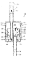
図1は、本発明に係わるフィルターユニットの特に有用な実施態様の一例を示すものである。フィルターユニット10は、雌ケース部材13と雄ケース部材15とが嵌合部17で連結されていて、両端が閉じた略円筒状に形成されている。そして、その略円筒状ケース内に、フィルター12と遮蔽部材26とが収容されて構成されている。フィルター12は、雌ケース部材13の側壁に設けられた段差部25と、雌ケース部材13の底部に設けられたフィルター支持部33とで片側を支持され、反対側は遮蔽部材26の脚部32と接している。フィルター12と接する脚部32及びフィルター支持部33は、フィルター12の通気面を塞がないように、凸部先端で支持するように成形されている。雌ケース部材13には、痰などを吸入するための吸入チューブ20と連結される吸入口14と、吸入口14から体液溜め室18に通じる吸入管22が一体的に設けられていて、吸入管22はフィルター12を貫通している。すなわち、体液溜め室18は、フィルター12を挟んで吸入口14の反対側に位置する。また、雄ケース部材15には、吸引源24につながる吸引口16と、体液溜め室18から吸引口16に通じる吸引管23が一体的に設けられていて、吸引管23はフィルター12を貫通している。遮蔽部材26は、断面がL形の円環状で雌ケース部材13の内壁に沿う形状の遮蔽部28と、脚部32とで構成され、円環状遮蔽部28の開放された中央部が通気部30を形成している。
【0014】
本フィルターユニット10は次のようにして組み立てられる。まず、段差部25及びフィルター支持部材33に突き当たるまで、雌ケース部材13内にフィルター12を深く差し入れる。フィルター12には、吸引管23及び吸入管22を通すための孔が予め細めに設けてあって、上述の作業は、吸入管22をこの孔に通しながら行われる。次に、遮蔽部材26を雌ケース部材13に入れ、脚部32がフィルター12に接するようにして被せる。円環状の遮蔽部28が雌ケース部材13の内壁と嵌合して所定の位置に固定される。次いで、雄ケース部材15が被せられ、嵌合部17で凹凸嵌合して雌ケース部材13と連結されるが、同時に、吸引管23の先端部がフィルター12に予め設けられた孔に挿入される。このようにして組み立てられたフィルターユニット10は、フィルター12によって2室に区切られ、吸引管23及び吸入管22がフィルター12を隙間なく貫通した構造となっている。
【0015】
本例のフィルターユニット10によれば、吸引源24によって吸引される空気の流れは、矢印の向きで示されるように、吸入口14から吸入管22を通って体液溜め室18に入り、次いで、フィルター12、吸引管23を通過して吸引口16に至る。体液を取り除こうとする施術者は、フィルターユニット10を片手に持ち、もう一方の手で吸入チューブ20を操作し、その先端を痰が詰まっている咽喉に当てる。痰は上述の空気の流れに乗って吸引され、フィルターユニット10の内に取り出される。
【0016】
吸入チューブ20の先端から吸入された痰などの体液は、吸入口14、吸入管22を経て体液溜め室18内に排出されるが、吸入管22の先端が、フィルター12とは逆側の、雄ケース部材15の方を向いているので、飛び出す体液が直接フィルター12に当たることが避けられる。このため、体液によるフィルター12の目詰まりが軽減される。また、遮蔽部材26が設けられているので、雌ケース部材13の内壁を伝わる体液が遮蔽部28によって遮られることになり、フィルター12の目詰まりがさらに軽減される。遮蔽部28は断面L形の円環状とされ、雌ケース部材13の内壁に密着して、断面コの字形の円環状溝を形成するので、フィルターユニット10がどちらの方向に傾けられても、中に溜まった体液がフィルター12側に流れ出ることはない。
【0017】
フィルター12まで流れてきた液状の体液や、体液溜め室18内の空気に含まれる一部の体液は、フィルター12により捕捉され、清浄となった空気だけが吸引管23、吸引口16を通って吸引源24に流れる。フィルター12の端部は雌ケース部材13の内壁と隙間なく接していて、体液溜め室18を締め切っているので、フィルターユニット10がどのように乱暴に扱われても、体液が吸引口16に漏れ出ることはない。このため、本発明のフィルターユニット10は、使い捨て用として気軽に利用される。遮蔽部材26の中央部には通気部30が設けられ、フィルター12の両面は十分広く開放されているので、フィルター12全面が目詰まりする恐れは少ない。また、フィルター12を通過する時の圧力損失が大きくならないので、口で吸引する程度の比較的弱い吸引源24を用いることができる。
【0018】
本例のフィルターユニット10では、吸入口14と吸引口16がフィルター12を挟んで両側に設けられていて、例えば、一般家庭で用いる、口で吸引する応急吸引器として用いられると非常に便利である。すなわち、施術者は吸引口16を口に挟み、咽喉などを上から覗きながら、下方にある吸入口14に接続された吸入チューブ20を操作できるので、操作性が格別に良好となる。また、吸入口14が咽喉などの直ぐ近くになるので、吸入チューブ20を短くすることができ、痰をフィルターユニット10まで早く吸い上げて施術時間を短縮できる。このため、痰などが詰まった病人の負担も、施術者の負担も、共に軽減される効果がある。
【0019】
図2に示される別の実施例のフィルターユニット10では、吸入口14及び吸引口16が同一側に設けられている。本例においても、吸入管22がフィルター12を貫通しているので、体液溜め室18に飛び出す体液が直接フィルター12に当たることが防止されている。また遮蔽部材26が設けられているので、雌ケース部材13の内壁を伝ってフィルター12に流れる体液が阻止される。図1に示されるフィルターユニット10と異なるのは、フィルター12を通過した空気を吸入口14と同じ方向に設けた吸引口16に向けることだけである。
【0020】
本例のフィルターユニット10は、真空ポンプなどの吸引源24を利用する場合に特に適している。真空ポンプなどの吸引源24を利用する場合には、吸引源24を作動又は停止するためのスイッチ操作が必要であり、フィルターユニット10を片手に持ち、吸入チューブ20をもう一方の手で扱うのでは、吸引源24の操作ができず、いったん吸入作業を中断しなくてはならない。しかしながら、例えば図2に示されるように、フィルターユニット10の側壁に吸引源24のスイッチ38を取り付け、フィルターユニット10と共に握りながらスイッチ38を操作するようにすれば、もう一方の手が何時でも自由になるので、吸入作業を中断しなくてもよくなる。
【0021】
図3に例示されるフィルターユニット10は、吸入口14、体液溜め室18、フィルター12、吸引口16が直列的に設けられた単純な構造とされている。本フィルターユニット10は、特に、家庭用で、口で吸引する吸引器などに利用されるものであり、小型で軽量で安価である。すなわち、吸入口14、体液溜め室18、フィルター12、吸引口16が直列的に配設されるので、フィルターユニット10を細くすることができ、吸入口14を下側にして用いることを前提にして、遮蔽部材26を省いてある。その結果、小型、軽量化が可能になり、コストも大幅に低減される。フィルターユニット10が細くなることに伴い、フィルター12の有効面積が減り目詰まりしやすくなるが、体液溜め室18内の体液は雄ケース部材15の底部40に溜まるので、フィルターユニット10を逆さまにしない限り、フィルター12側に流れることはない。また、目詰まり防止性を改善するためフィルター12が厚くされている。
【0022】
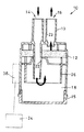
図4に例示されるフィルターユニット10は、吸入口14と吸引口16が隣り合って設けられていて、図2に示されるフィルターユニット10と同様、真空ポンプなどの吸引源24を利用する場合に特に適している。同図に示される向きでフィルターユニット10を握り、例えば、その上部にスイッチ38を取り付け親指で操作できる特徴がある。フィルター12が体液溜め室18の上に位置しているため、吸入管22から出る体液がフィルター12に直接当たることは少ないので遮蔽部材26は省かれている。
【0023】
すでに説明したように、吸入管22がフィルター12を貫通して設けられれば、吸入管22から飛び出す体液がフィルター12に直接当たって目詰まりさせることを防止できる効果がある。しかしながら、体液溜め室18の上方にフィルター12があるように限定された用い方をされるフィルターユニット10では、重力に逆らって体液が上方に飛びにくいので、必ずしも、吸入管22をフィルター12に貫通して設ける必要がない。
【0024】
また、すでに説明したように、遮蔽部材26が設けられれば、フィルターユニット10をどの方向に傾けて使用しても、雌ケース部材13を伝わる体液の流れが遮られて、フィルター12が目詰まりしにくくなる。しかしながら、体液溜め室18の上方にフィルター12があるように限定された用い方をされるフィルターユニット10では、体液は雄ケース部材15の底部40に溜まってフィルター12に流れることがないので、必ずしも遮蔽部材26を設ける必要がない。
【0025】
図1〜図4に示されたフィルターユニット10の形状は略円筒状であったが、本発明のフィルターユニット10は、円錐状や角柱状などの種々の形状とされてもよい。また、携帯時は折り畳まれていて、使用時に組み立てる構成とされても便利である。
【0026】
フィルター12の形状や構成は、図1〜図4に示された例示に限定されない。例えば、図5に示されるフィルター12は、比較的粗くて嵩高のフィルター材42と、比較的密のフィルター材44との2層で構成されていて、フィルター材42は主に高粘度の体液を捕捉し、フィルター材44はその後に残った低粘度体液を捕捉しようとするものである。また、図6に示されるフィルター12は、シャーレ状に周囲が立ち上がった形状とされてるため、通気する表面積が広がって目詰まりしにくくなっている。この他、襞を付けて表面積を広げるなどの、種々の工夫を採用できる。
【0027】
また、遮蔽部材26の形状や係止方法も、上述した例に限定されない。例えば、図6に示される遮蔽部材26は、雌ケース部材13に設けた段差部46に乗せられることで位置決めされていて、脚部32無しに、フィルター12と所定の距離だけ離れて係止される。このため、フィルター12の表面は、接触するものが無くて完全に開放され、フィルター機能が損なわれることがない。
【0028】
あるいは、図7に示される遮蔽部材26は、断面がコの字形の溝が円環状に形成された形状とされていて、雌ケース部材13の内壁に沿ってスムーズに滑り移動できるため、フィルターユニット10の組み立て作業が容易になる特徴がある。
【0029】
あるいは、図8に示される、末広がりに形成された遮蔽部材26は、フィルター12と周辺部だけで接触するので、フィルター12の有効表面積をほとんど変えないという特徴がある。
【0030】
体液溜め室18まで吸引されてきた体液が、フィルター12を目詰まりさせないように、吸入管22をフィルター12に貫通させたり、遮蔽部材26を設けたりする工夫を行ってきた。目詰まりをさらに防ぐ工夫として、吸液部材を体液溜め室18内に設けることもできる。図9に示されるフィルターユニット10では、吸液部材48が雌ケース部材13の内壁に沿って設けられており、体液から水分を吸収して粘度を高め、流動性を減じて体液がフィルター12へ移動しないようにされている。吸液部材48には、高分子吸水体やフェルトなどが用いられる。
【0031】
フィルター12の材質は特に限定されず、換気口や集塵機、掃除機などに通常用いられる、紙、布、不織布等々からなるエアーフィルター材が好ましく用いられる。中でも、不織布からなるエアーフィルター材は、嵩高なので目詰まりしにくく、成形性に優れているので最適の形状に加工することができ、比較的安価なので特に好ましく用いられる。ポリエステル繊維、ポリプロピン繊維、ポリアクリル繊維などの有機繊維で構成された不織布が用いられれば、使用後は環境を汚染することなく焼却処分できる。また、消毒・殺菌機能、消臭機能、脱臭機能などが付与されたフィルター12とされてもい。あるいは、体液成分で色や形が変化するフィルター12とされてもよい。しかしながら、フィルター12であらゆる種類の細菌やウィルスを100パーセント捕捉することは困難であり、フィルターユニット10を口で吸引して使用する場合などには、専門医師の十分な指導を受けることが望まれる。
【0032】
雌ケース部材13や雄ケース部材15や遮蔽部材26などの材質は、ポリプロピレン、ABS樹脂、ポリカーボネート等々のプラスチックが好ましく用いられる。軽量で成形性に優れ、低コストであり、透明性に優れているのでフィルターユニット10内の体液を良く観察できるし、フィルター12共々焼却処分できて、焼却熱を回収使用することもできる。また、消毒・殺菌機能、消臭機能、脱臭機能などを備えた材料を用いても、あるいは、こういう材料が付加されてもよい。
【0033】
本発明に係わる体液吸引器は、上述したフィルターユニット10を含み、少なくとも吸入チューブ20が吸入口14に連結されたものである。図10に例示される体液吸引器34は、図1に示されるフィルターユニット10の吸入口14に吸入チューブ20が連結され、その吸入チューブ20の先端に、吸入先端部材36が連結された構成とされている。吸入チューブ20は、シリコンゴムや軟質のポリオレフィン系樹脂からなり、柔軟性に優れて容易に屈曲するものである。
【0034】
本例の体液吸引器34は次のようにして使用される。すなわち、施術者は片手でフィルターユニット10を握って保持し、もう一方の片手で吸入チューブ20の先端近くを摘んで、咽喉部などの体液摘出箇所に吸入先端部材36を当てる。そして、吸引口16を口にくわえて吸い込むことにより、痰などの体液を吸引・除去するのである。あるいは、次のようにしても使用できる。すなわち、吸引口16を口にくわえることによりフィルターユニット10を保持し、フリーになった両手で、吸入チューブ20を集中的に操作する。あるいはまた、吸引チューブなどを介して、吸引口16と、真空ポンプなどの吸引源24とをつないで使用することもできる。真空ポンプなどの吸引源24を用いる場合には、吸引口16と吸引源24との間に、何らかの真空度調整手段が設けられるのが好ましい。
【0035】
本発明の体液吸引器34は、小型で軽量のフィルターユニット10が用いられてるため携帯し易く、特に、口で吸い込む方式とされれば、真空ポンプなどの吸引源24を必要としないので、一般家庭や中小の医療施設で用いるのに大変便利である。さらに、口でくわえられる形状の吸引口16とされれば、口でフィルターユニット10を保持し、自由となった両手で、吸入チューブ20の操作や患者の手助けができるので、格別に便利になる。
【0036】
また、本発明の体液吸引器34によれば、痰などの体液がフィルター12によって確実に取り除かれるので、口で吸引しても、口の中に体液が入り込むことがなく、従来の、衛生上あるいは精神上の問題が解消される。また、使用後の体液吸引器34は、そのまま廃棄されるので、洗浄や消毒の面倒な作業が不要になる。また、廃棄される体液吸引器34は丸ごと焼却できて、その燃焼熱を有効利用することもできる。フィルターユニット10、吸入チューブ20、吸入先端部材36などの材質をポリオレフィン系樹脂とすれば、焼却しても有毒ガスはほとんど発生しない。
【0037】
吸入先端部材36の役割は、吸入チューブ20の先端が、口腔内面などに触って塞がれて吸着してしまい、離れなくなることを防止することにある。図11は、吸入先端部材36の一例を示している。吸入先端部材36の先端には、先端面と側面とを切り欠く溝50が6箇所に設けられていて、先端面が塞がれても、側面から空気が吸引される構造とされている。すなわち、吸入先端部材36は空気導入機構を備えている。このため、例えば、痰の取り出し作業中に、吸入先端部材36が口腔内面などに接触して塞がれても、溝を通って側面から空気が吸引されることになって、吸入チューブ20内の搬送空気の流量は低下せず、先端が真空吸着固定することなく、快適に吸引できる。鼻汁などを吸入する場合などでは、鼻孔に合わせた形状の吸入先端部材36が使用されるのが好ましい。しかしながら、吸入チューブ20の先端が塞がれることが少ない使用方法では、必ずしも吸入先端部材36は必要とされない。
【0038】
以上、本発明に係わる使い捨ての体液フィルターユニット及び体液吸引器について詳細に説明してきたが、本発明は上述の引用例示に限定されず、フィルターユニットやフィルターの形状や材質や構成、体液吸引器の構成などにつき、その趣旨を逸脱しない範囲内で種々なる改良、修正、変化を加えた態様で実施し得るものである。
【0039】
【発明の効果】
本発明に係わる使い捨ての体液フィルターユニットによれば、吸入されて取り出された痰などの体液が、フィルターと遮蔽部材によって捕捉されるので、口などの吸引源には汚れた空気が流れない。また、フィルターユニットを傾けても転倒させても、フィルター機能は変化しないので手軽に取り扱える。
【0040】
また、本発明に係わる体液フィルターユニットは使い捨てされるので、洗浄や消毒などの面倒な作業が省かれる。
【0041】
さらに、このような体液フィルターユニットにおいて、吸入口から体液溜め室に空気を導く吸入管が、フィルターを貫通して設けられれば、吸入管から飛び出す体液がフィルターに直接当たって目詰まりさせることが防止される。
【0042】
さらにまた、このような体液フィルターユニットにおいて、吸入口と吸引口とがフィルターを挟む両側に設けられれば、施術者は吸引口を口に挟み、口腔内などを上から覗きながら、下方にある吸入口に接続された吸入チューブを操作できるので、操作性が格別に良好となる。また、吸入口を咽喉などの施術場所に近づけられるようになるので、吸入チューブを短くすることができ、痰などをフィルターユニットまで素早く吸い上て、施術時間を短縮できるようになる。このため、痰などが詰まった病人の負担も、施術者の負担も共に軽減される。
【0043】
またさらに、このような体液フィルターユニットにおいて、体液溜め室の内壁に沿った形状の体液遮蔽部を周辺に備え、通気部を略中央部に備えた遮蔽部材が、体液溜め室とフィルターとの間に設けられれば、ケース内壁を伝わる体液の流れが遮られて、フィルターが目詰まりしにくくなる。
【0044】
また、本発明に係わる使い捨ての体液吸引器によれば、小型で軽量のフィルターユニットが用いられてるため携帯し易く、特に、口で吸い込む方式とされれば、真空ポンプなどの吸引源を必要としないので、真空ポンプなどの吸引源を常備しない一般家庭や派遣介護者が応急的に用いるのに大変便利である。また、口でくわえられる形状の吸引口とされれば、口でフィルターユニットを保持し、自由となった両手で、吸入チューブの操作や患者の手助けができるので、格別に便利になる。
【0045】
また、本発明の体液吸引器によれば、痰などの体液がフィルターユニットによって確実に取り除かれるので、口で吸引しても、口の中に体液が入り込むことがなく、従来の、衛生上あるいは精神上の問題が解消される。また、使用後の体液吸引器は、そのまま廃棄されるので、洗浄や消毒の面倒な作業が不要になる。また、廃棄される体液吸引器は丸ごと焼却できて、塩化ビニル系の樹脂が使用されてなければダイオキシンなどの有害成分の発生が少なく、その焼却熱を熱リサイクルすることもできる。
【0046】
さらに、吸入チューブの先端に、空気導入機構を備えた吸入先端部材が連結されれば、吸入チューブの先端が、口腔内面などに吸着してしまい離れなくなることが防止され、施術の作業性が向上する。
【0047】
本発明の体液吸引器は、上述した種々の効果を発揮して、痰や鼻汁等の体液の除去に主に使用されるが、吸引体液の検査までの、移し替えが不要の保存容器として使用されたり、外耳関連病の清掃などにも使用できる。
【図面の簡単な説明】
【図1】本発明に係るフィルターユニットの一例を示す正面断面図である。
【図2】本発明に係るフィルターユニットの他の一例を示す正面断面図である。
【図3】本発明に係るフィルターユニットの他の一例を示す正面断面図である。
【図4】本発明に係るフィルターユニットの他の一例を示す正面断面図である。
【図5】本発明に係り、フィルターを例示する正面断面図であり、同図(a)は2層構造、同図(b)はシャーレ形状の例である。
【図6】本発明に係り、遮蔽部材の一例を示す正面断面図である。
【図7】本発明に係り、遮蔽部材の他の一例を示す正面断面図である。
【図8】本発明に係り、遮蔽部材の他の一例を示す正面断面図である。
【図9】本発明に係るフィルターユニットの他の一例を示す正面断面図である。
【図10】本発明に係る体液吸引器の一例を示す正面断面図である。
【図11】本発明に係り、吸入先端部材の一例を示し、同図(a)は正面図、同図(b)は底面図、同図(c)は同図(b)におけるA−A断面図である。
【符号の説明】
10:フィルターユニット
12:フィルター
13:雌ケース部材
14:吸入口
15:雄ケース部材
16:吸引口
17:嵌合部
18:体液溜め室
20:吸入チューブ
21:吸引チューブ
22:吸入管
23:吸引管
24:吸引源
25、46:段差部
26:遮蔽部材
28:遮蔽部
30:通気部
32:遮蔽部材の脚部
33:フィルター支持部
34:体液吸引器
36:吸入先端部材
38:スイッチ
40、44:フィルター材
48:吸液部材
50:溝[0001]
BACKGROUND OF THE INVENTION
The present invention relates to a disposable aspirator used for taking out clogged sputum and nasal discharge.
[0002]
[Problems to be solved by the invention]
Sick and sick people who are weak in physical strength may not be able to spit out the throat clogged on their own, and are taken out by medical facilities and caregivers. Similarly, when an infant or the like clogs nasal discharge, the parent or the like sucks out nasal discharge with his / her mouth. In medical facilities, these body fluids are taken out using a suction source such as a vacuum pump, but the suction device is large and difficult to move, and it is troublesome to clean and disinfect the suction tube and sputum after use. There was. Even after cleaning and disinfection, there was always a risk of infection when reused.
[0003]
On the other hand, in a general household without such a suction device, a method of sucking out by mouth using a suction tube like a straw has been taken. For this reason, sputum or the like may enter the mouth, and there is a risk that the patient's illness will become infected, which has become a major sanitary or mental problem.
[0004]
Therefore, the present inventor has intensively studied a disposable body fluid filter unit and a body fluid suction device that are convenient to carry and can be easily used anywhere, can completely capture body fluids such as sputum and nasal discharge, and do not require cleaning or disinfection. As a result, the present invention has been achieved.
[0005]
[Means for Solving the Problems]
A disposable body fluid filter unit according to the present invention is a filter unit used for removing body fluids such as clogged sputum and nasal discharge, and an inhalation tube for inhaling the body fluid by a flow of air that sucks the body fluid A suction port connected to the suction port, a body fluid reservoir chamber, a filter, and a suction port connected to a suction source, and a suction pipe that guides air from the suction port to the body fluid reservoir chamber passes through the filter. It is characterized by being provided.
[0006]
Further, in this filter unit, an intake pipe that guides air from the intake port to the body fluid reservoir chamber is provided through the filter.
[0007]
Furthermore, in this filter unit, the suction port and the suction port are provided on both sides of the filter.
[0008]
Also, disposable fluid filter unit according to the present invention is a filter unit used to remove bodily fluids such as waiting sputum and nasal discharge, the flow of air for sucking the body fluid, for sucking body fluid A suction port connected to the suction tube, a body fluid reservoir, a filter, and a suction port connected to a suction source in that order, and is provided with a body fluid shield around the inner wall of the body fluid reservoir. The shielding member having the ventilation portion at the substantially central portion is provided between the body fluid reservoir and the filter.
[0009]
Further, the gist of the disposable body fluid suction device according to the present invention includes the above-described filter unit, and at least the suction tube is connected to the suction port.
[0010]
Furthermore, in this suction device, a suction tip member having an air introduction mechanism is connected to the tip of the suction tube.
[0011]
Furthermore, in this suction device, the suction port has a shape that can be held by the mouth.
[0012]
DETAILED DESCRIPTION OF THE INVENTION
Next, embodiments of the disposable body fluid filter unit and the suction device according to the present invention will be described in detail based on the drawings.
[0013]
FIG. 1 shows an example of a particularly useful embodiment of a filter unit according to the present invention. The
[0014]
The
[0015]
According to the
[0016]
Body fluids such as sputum sucked from the tip of the
[0017]
The liquid body fluid that has flowed to the
[0018]
In the
[0019]
In the
[0020]
The
[0021]
The
[0022]
The
[0023]
As already described, if the
[0024]
In addition, as already described, if the shielding
[0025]
Although the shape of the
[0026]
The shape and configuration of the
[0027]
Further, the shape and the locking method of the shielding
[0028]
Alternatively, the shielding
[0029]
Alternatively, the shielding
[0030]
In order to prevent the bodily fluid sucked up to the bodily
[0031]
The material of the
[0032]
For the material of the
[0033]
The body fluid suction device according to the present invention includes the
[0034]
The
[0035]
The bodily
[0036]
Further, according to the body
[0037]
The role of the
[0038]
As described above, the disposable body fluid filter unit and body fluid suction device according to the present invention have been described in detail. However, the present invention is not limited to the above cited examples, the shape, material and configuration of the filter unit and filter, and the body fluid suction device. The configuration and the like can be implemented with various improvements, corrections, and changes within a range not departing from the spirit thereof.
[0039]
【The invention's effect】
According to the disposable body fluid filter unit according to the present invention, body fluid such as sputum that is inhaled and taken out is captured by the filter and the shielding member, so that dirty air does not flow to the suction source such as the mouth. Even if the filter unit is tilted or overturned, the filter function does not change, so it can be handled easily.
[0040]
Further, since the body fluid filter unit according to the present invention is disposable, troublesome work such as cleaning and disinfection is omitted.
[0041]
Furthermore, in such a body fluid filter unit, if a suction pipe that guides air from the suction port to the body fluid reservoir chamber is provided through the filter, body fluid that jumps out of the suction pipe is prevented from directly hitting the filter and causing clogging. Is done.
[0042]
Furthermore, in such a body fluid filter unit, if the suction port and the suction port are provided on both sides of the filter, the practitioner sandwiches the suction port between the mouths and looks into the oral cavity from above while performing the inhalation below. Since the suction tube connected to the mouth can be operated, the operability is particularly good. Further, since the suction port can be brought closer to the treatment place such as the throat, the suction tube can be shortened, and the treatment time can be shortened by quickly sucking up the sputum and the like to the filter unit. For this reason, both the burden on the sick and the practitioner are reduced.
[0043]
Furthermore, in such a body fluid filter unit, a shielding member having a body fluid shielding portion having a shape along the inner wall of the body fluid reservoir chamber in the periphery and a ventilation portion in a substantially central portion is provided between the body fluid reservoir chamber and the filter. If it is provided, the flow of body fluid that travels along the inner wall of the case is blocked, and the filter is less likely to be clogged.
[0044]
In addition, according to the disposable body fluid suction device according to the present invention, a small and lightweight filter unit is used, so that it is easy to carry. Especially, if a suction system is used, a suction source such as a vacuum pump is required. Therefore, it is very convenient for emergency use by ordinary households and temporary caregivers who do not always have a suction source such as a vacuum pump. Also, if the suction port has a shape that can be held by the mouth, the filter unit can be held by the mouth, and the freed hands can operate the suction tube and help the patient, which is particularly convenient.
[0045]
Further, according to the bodily fluid suction device of the present invention, bodily fluids such as sputum are reliably removed by the filter unit, so that bodily fluids do not enter the mouth even if sucked by the mouth, Mental problems are resolved. Further, since the used body fluid aspirator is discarded as it is, the troublesome work of cleaning and disinfection becomes unnecessary. Moreover, the whole body aspirator to be discarded can be incinerated. If no vinyl chloride resin is used, the generation of harmful components such as dioxin is small, and the incineration heat can be heat recycled.
[0046]
Furthermore, if a suction tip member equipped with an air introduction mechanism is connected to the tip of the suction tube, the tip of the suction tube is prevented from adsorbing to the inner surface of the oral cavity and the like, and the workability of the treatment is improved. To do.
[0047]
The bodily fluid aspirator of the present invention exerts the various effects described above and is mainly used for removing bodily fluids such as sputum and nasal discharge, but is used as a storage container that does not require transfer until the inspection of aspirated bodily fluids It can also be used to clean external ear related diseases.
[Brief description of the drawings]
FIG. 1 is a front sectional view showing an example of a filter unit according to the present invention.
FIG. 2 is a front sectional view showing another example of the filter unit according to the present invention.
FIG. 3 is a front sectional view showing another example of the filter unit according to the present invention.
FIG. 4 is a front sectional view showing another example of the filter unit according to the present invention.
5A and 5B are front sectional views illustrating a filter according to the present invention, in which FIG. 5A is an example of a two-layer structure and FIG. 5B is an example of a petri dish shape.
FIG. 6 is a front sectional view showing an example of a shielding member according to the present invention.
FIG. 7 is a front sectional view showing another example of the shielding member according to the present invention.
FIG. 8 is a front sectional view showing another example of the shielding member according to the present invention.
FIG. 9 is a front sectional view showing another example of the filter unit according to the present invention.
FIG. 10 is a front sectional view showing an example of a body fluid aspirator according to the present invention.
11A and 11B show an example of a suction tip member according to the present invention, in which FIG. 11A is a front view, FIG. 11B is a bottom view, and FIG. 11C is AA in FIG. It is sectional drawing.
[Explanation of symbols]
10: Filter unit 12: Filter 13: Female case member 14: Suction port 15: Male case member 16: Suction port 17: Fitting portion 18: Body fluid reservoir chamber 20: Suction tube 21: Suction tube 22: Suction tube 23: Suction Tube 24:
Claims (6)
該体液を吸入するための吸入チューブと連結される吸入口、
体液溜め室、
フィルター、
吸引源とつながる吸引口、
の順となるように構成され、
前記吸入口から前記体液溜め室に空気を導く吸入管が、前記フィルターを貫通して設けられたことを特徴とする、使い捨ての体液フィルターユニット。A filter unit used to remove body fluids such as clogged sputum and nasal discharge, and the flow of air that sucks the body fluids
An inlet connected to an inhalation tube for inhaling the body fluid;
Body fluid reservoir,
filter,
Suction port connected to the suction source,
Is configured in the order of
A disposable body fluid filter unit, characterized in that a suction pipe for guiding air from the suction port to the body fluid reservoir chamber is provided through the filter.
該体液を吸入するための吸入チューブと連結される吸入口、
体液溜め室、
フィルター、
吸引源とつながる吸引口、
の順となるように構成され、
前記体液溜め室の内壁に沿った形状の体液遮蔽部を周辺に備え、通気部を略中央部に備えた遮蔽部材が、体液溜め室とフィルターとの間に設けられたことを特徴とする、使い捨ての体液フィルターユニット。A filter unit used to remove body fluids such as clogged sputum and nasal discharge, and the flow of air that sucks the body fluids
An inlet connected to an inhalation tube for inhaling the body fluid;
Body fluid reservoir,
filter,
Suction port connected to the suction source,
Is configured in the order of
A body fluid shielding part having a shape along the inner wall of the body fluid reservoir chamber is provided in the periphery, and a shielding member provided with a ventilation part in a substantially central part is provided between the body fluid reservoir chamber and the filter, Disposable body fluid filter unit.
Priority Applications (8)
| Application Number | Priority Date | Filing Date | Title |
|---|---|---|---|
| JP32351599A JP4442969B2 (en) | 1999-11-15 | 1999-11-15 | Disposable body fluid filter unit and body fluid aspirator |
| AU14132/01A AU1413201A (en) | 1999-11-15 | 2000-11-15 | Disposable body fluid filter unit, disposable body fluid sucking device, and body fluid sucking source |
| EP00976273A EP1234589A1 (en) | 1999-11-15 | 2000-11-15 | Disposable body fluid filter unit, disposable body fluid sucking device, and body fluid sucking source |
| JP2001538009A JPWO2001036020A1 (en) | 1999-11-15 | 2000-11-15 | Disposable body fluid filter unit, disposable body fluid aspirator, and suction source |
| PCT/JP2000/008064 WO2001036020A1 (en) | 1999-11-15 | 2000-11-15 | Disposable body fluid filter unit, disposable body fluid sucking device, and body fluid sucking source |
| US09/914,410 US6589219B1 (en) | 1999-11-15 | 2000-11-15 | Disposable body fluid filter unit, disposable body fluid sucking device, and body fluid sucking source |
| CNB008171424A CN1246049C (en) | 1999-11-15 | 2000-11-15 | Disposable body fluid filter unit, disposable body fluid sucking device, and body fluid sucking source |
| HK03107042A HK1054702A1 (en) | 1999-11-15 | 2003-09-30 | Disposable body fluid filter unit |
Applications Claiming Priority (1)
| Application Number | Priority Date | Filing Date | Title |
|---|---|---|---|
| JP32351599A JP4442969B2 (en) | 1999-11-15 | 1999-11-15 | Disposable body fluid filter unit and body fluid aspirator |
Publications (2)
| Publication Number | Publication Date |
|---|---|
| JP2005287520A JP2005287520A (en) | 2005-10-20 |
| JP4442969B2 true JP4442969B2 (en) | 2010-03-31 |
Family
ID=18155558
Family Applications (2)
| Application Number | Title | Priority Date | Filing Date |
|---|---|---|---|
| JP32351599A Expired - Fee Related JP4442969B2 (en) | 1999-11-15 | 1999-11-15 | Disposable body fluid filter unit and body fluid aspirator |
| JP2001538009A Pending JPWO2001036020A1 (en) | 1999-11-15 | 2000-11-15 | Disposable body fluid filter unit, disposable body fluid aspirator, and suction source |
Family Applications After (1)
| Application Number | Title | Priority Date | Filing Date |
|---|---|---|---|
| JP2001538009A Pending JPWO2001036020A1 (en) | 1999-11-15 | 2000-11-15 | Disposable body fluid filter unit, disposable body fluid aspirator, and suction source |
Country Status (7)
| Country | Link |
|---|---|
| US (1) | US6589219B1 (en) |
| EP (1) | EP1234589A1 (en) |
| JP (2) | JP4442969B2 (en) |
| CN (1) | CN1246049C (en) |
| AU (1) | AU1413201A (en) |
| HK (1) | HK1054702A1 (en) |
| WO (1) | WO2001036020A1 (en) |
Cited By (1)
| Publication number | Priority date | Publication date | Assignee | Title |
|---|---|---|---|---|
| KR200482784Y1 (en) * | 2016-08-11 | 2017-03-03 | (주)메가메디칼 | medical suction machine |
Families Citing this family (40)
| Publication number | Priority date | Publication date | Assignee | Title |
|---|---|---|---|---|
| JP4624613B2 (en) * | 2001-09-14 | 2011-02-02 | 一郎 渋谷 | Body fluid suction system |
| US7244236B2 (en) * | 2003-05-16 | 2007-07-17 | M D Technologies Inc. | Specimen trap with strainer |
| US7488312B2 (en) * | 2005-02-23 | 2009-02-10 | Rogers Joann E | Polyp screen |
| DE202006020723U1 (en) * | 2006-03-24 | 2010-04-29 | Atmos Medizintechnik Gmbh & Co. Kg | suction |
| US20080135049A1 (en) * | 2006-12-07 | 2008-06-12 | George Lee | Filtering Means For Suction Tube |
| CA2726995C (en) | 2008-06-04 | 2017-12-19 | Kci Licensing, Inc. | Reduced-pressure, liquid-collection canister with multi-orientation filter |
| US9211486B2 (en) * | 2008-06-04 | 2015-12-15 | Kci Licensing, Inc. | Reduced-pressure, liquid-collection canister with multi-orientation filter |
| AU2015221508B2 (en) * | 2008-06-04 | 2017-08-31 | Solventum Intellectual Properties Company | Reduced-pressure, liquid-collection canister with multi-orientation filter |
| DE102008027486B4 (en) * | 2008-06-10 | 2013-11-07 | Human Med Ag | Method and apparatus for separating tissue cells from a fluid |
| ES1068572Y (en) * | 2008-08-04 | 2009-02-01 | Garcia M Del Carmen Rodriguez | NASAL VACUUM CLEANER DEVICE FOR BABIES AND CHILDREN OF MANUAL OPERATION |
| EP2156853A1 (en) * | 2008-08-19 | 2010-02-24 | Aesculap AG | Medical product for treatment of sinusitis |
| CA2691431C (en) * | 2009-01-28 | 2018-03-20 | Fuel Transfer Technologies Inc. | A non-overflow liquid delivery system |
| JP5134038B2 (en) * | 2010-04-30 | 2013-01-30 | 広陵化学工業株式会社 | Sample collection device for aspiration and testing of otorrhea, nasal discharge and other secretions |
| JP6004443B2 (en) * | 2010-08-18 | 2016-10-05 | ケーシーアイ ライセンシング インコーポレイテッド | Depressurized liquid collection canister in multiple orientations |
| US8758315B2 (en) | 2012-02-21 | 2014-06-24 | Kci Licensing, Inc. | Multi-orientation canister for use with a reduced pressure treatment system |
| CA3019704C (en) * | 2012-02-21 | 2020-06-16 | Kci Licensing, Inc. | A multi-orientation canister for use with a reduced pressure treatment system |
| JP5993645B2 (en) * | 2012-07-20 | 2016-09-14 | 武内容器株式会社 | Nasal aspirator |
| JP6013114B2 (en) * | 2012-09-27 | 2016-10-25 | テルモ株式会社 | Suction system |
| CN103202715A (en) * | 2013-03-20 | 2013-07-17 | 钱正环 | Phlegm taking sample keeping cup |
| US20150133816A1 (en) * | 2013-11-11 | 2015-05-14 | James Zhou Liu | Complete upper respiratory tract cleansing system and its use |
| JP6053718B2 (en) * | 2014-05-13 | 2016-12-27 | 柳瀬ワイチ株式会社 | Body fluid aspirator |
| USD771832S1 (en) | 2014-06-17 | 2016-11-15 | Medline Industries, Inc. | Lid and screen assembly of a sample collection container with screen |
| US9993584B2 (en) * | 2015-03-10 | 2018-06-12 | Neilmed Pharmaceuticals, Inc. | Nasal aspirator |
| WO2016191502A1 (en) * | 2015-05-28 | 2016-12-01 | Romanick Norman | Prevention of use of a contaminated medical product |
| EP3978043B1 (en) * | 2015-07-13 | 2024-01-31 | ConMed Corporation | Surgical suction device that uses positive pressure gas |
| TWI603749B (en) * | 2015-09-21 | 2017-11-01 | 陳郁枝 | Nasal suction device |
| DK3359052T3 (en) | 2015-10-09 | 2021-07-05 | Arc Medical Design Ltd | Tissue collection device and method of use |
| US9671318B1 (en) | 2015-12-02 | 2017-06-06 | Medline Industries, Inc. | Specimen collector |
| GB2547012B (en) * | 2016-02-04 | 2018-12-19 | Aspirate N Go Ltd | Pump assembly suitable for use in aspirators |
| USD846733S1 (en) | 2017-04-04 | 2019-04-23 | Arc Medical Design Limited | Specimen trap |
| USD846732S1 (en) | 2017-04-04 | 2019-04-23 | Arc Medical Design Limited | Specimen trap |
| WO2018226726A1 (en) * | 2017-06-05 | 2018-12-13 | Bateman Bottle, Llc | Device for removal of implants and associated method of use |
| CN107929828A (en) * | 2017-12-14 | 2018-04-20 | 段书霞 | Nose sucking device |
| KR20190118413A (en) * | 2018-04-10 | 2019-10-18 | 봄텍전자 주식회사 | Exchangeable filter provided between multi-needle module and automatic procedure apparatus |
| CN109125819B (en) * | 2018-07-05 | 2021-05-25 | 南方医科大学南方医院 | Negative pressure sputum aspirator capable of preventing sputum from flowing reversely |
| USD1024310S1 (en) | 2019-03-28 | 2024-04-23 | Bateman Bottle, Llc | Implant removal device |
| USD964553S1 (en) | 2020-05-29 | 2022-09-20 | Keymed (Medical & Industrial Equipment) Limited | Medical instrument |
| US11207057B1 (en) * | 2020-08-07 | 2021-12-28 | Cyrano Medical, Inc. | Nasopharyngeal sample collection devices and methods |
| CN112274709A (en) * | 2020-09-30 | 2021-01-29 | 赵宏伟 | Oral or nasal negative pressure treatment or smoking and drug rehabilitation device and smoking and drug rehabilitation method |
| CN216824306U (en) * | 2021-12-24 | 2022-06-28 | 深圳市东疆科技有限公司 | Automatic nasal discharge collecting device |
Family Cites Families (15)
| Publication number | Priority date | Publication date | Assignee | Title |
|---|---|---|---|---|
| JPS45137Y1 (en) * | 1967-03-24 | 1970-01-07 | ||
| JPS5530494Y2 (en) * | 1977-11-22 | 1980-07-21 | ||
| US4747843A (en) * | 1986-05-15 | 1988-05-31 | C.R. Bard, Inc. | Control module for thoracic drainage apparatus |
| JPS638042U (en) * | 1986-07-02 | 1988-01-20 | ||
| JPS6384557A (en) * | 1986-09-29 | 1988-04-15 | カリツド サビ− カマス アル−タイエ | Portable medical apparatus |
| US4995386A (en) * | 1988-11-18 | 1991-02-26 | Ng Raymond C | Neonstal mucus extractor |
| US5098418A (en) * | 1989-08-24 | 1992-03-24 | Maitz Carlos A | Aspirator device for body fluids |
| JPH0511869Y2 (en) * | 1990-09-05 | 1993-03-25 | ||
| JPH0483249U (en) * | 1990-11-29 | 1992-07-20 | ||
| JP3204695B2 (en) * | 1991-09-25 | 2001-09-04 | 三菱レイヨン株式会社 | Liquid intrusion prevention device |
| JP2873295B2 (en) * | 1995-04-13 | 1999-03-24 | 永島医科器械株式会社 | Medical hoseless spray device |
| GB9523253D0 (en) * | 1995-11-14 | 1996-01-17 | Mediscus Prod Ltd | Portable wound treatment apparatus |
| JPH1094544A (en) * | 1996-08-02 | 1998-04-14 | Olympus Optical Co Ltd | Surgical device for peeling |
| WO1999053819A2 (en) * | 1998-04-18 | 1999-10-28 | Chang Yeun Lee | Snivel suction instrument |
| US6352525B1 (en) * | 1999-09-22 | 2002-03-05 | Akio Wakabayashi | Portable modular chest drainage system |
-
1999
- 1999-11-15 JP JP32351599A patent/JP4442969B2/en not_active Expired - Fee Related
-
2000
- 2000-11-15 US US09/914,410 patent/US6589219B1/en not_active Expired - Fee Related
- 2000-11-15 JP JP2001538009A patent/JPWO2001036020A1/en active Pending
- 2000-11-15 CN CNB008171424A patent/CN1246049C/en not_active Expired - Fee Related
- 2000-11-15 EP EP00976273A patent/EP1234589A1/en not_active Withdrawn
- 2000-11-15 AU AU14132/01A patent/AU1413201A/en not_active Abandoned
- 2000-11-15 WO PCT/JP2000/008064 patent/WO2001036020A1/en not_active Application Discontinuation
-
2003
- 2003-09-30 HK HK03107042A patent/HK1054702A1/en not_active IP Right Cessation
Cited By (1)
| Publication number | Priority date | Publication date | Assignee | Title |
|---|---|---|---|---|
| KR200482784Y1 (en) * | 2016-08-11 | 2017-03-03 | (주)메가메디칼 | medical suction machine |
Also Published As
| Publication number | Publication date |
|---|---|
| EP1234589A1 (en) | 2002-08-28 |
| JP2005287520A (en) | 2005-10-20 |
| AU1413201A (en) | 2001-05-30 |
| HK1054702A1 (en) | 2003-12-12 |
| WO2001036020A1 (en) | 2001-05-25 |
| JPWO2001036020A1 (en) | 2004-01-08 |
| US6589219B1 (en) | 2003-07-08 |
| CN1409642A (en) | 2003-04-09 |
| CN1246049C (en) | 2006-03-22 |
Similar Documents
| Publication | Publication Date | Title |
|---|---|---|
| JP4442969B2 (en) | Disposable body fluid filter unit and body fluid aspirator | |
| US5127411A (en) | Oral appliance for removing aerosols produced during dentistry | |
| US20210353395A1 (en) | Suction system | |
| KR20070083729A (en) | Nasal secretion aspiration device | |
| WO2017181879A1 (en) | Sputum suction tube for oral care | |
| JPH0374584B2 (en) | ||
| US6308707B1 (en) | Vacuum equipment for medical tables | |
| HU215563B (en) | Instrument for sucking of body, mainly nose secretion | |
| EP1474186B1 (en) | Infant nasal aspirator | |
| US20090105674A1 (en) | Snivel aspirator | |
| CN212395110U (en) | Oral medical aid | |
| JP4624613B2 (en) | Body fluid suction system | |
| JP2014212918A (en) | Reservoir for medical/caring suction material | |
| CN111840665B (en) | Nasal cavity suction device with splash prevention protection function | |
| CN215537012U (en) | Negative pressure drainage device with anti-virus function | |
| CN210932987U (en) | Mucus suction device and newborn asphyxia rescue equipment | |
| CN219963569U (en) | Sputum aspirator convenient to clearance | |
| CN215020959U (en) | Medical personnel protective cover with active exhausting and filtering functions | |
| KR102534264B1 (en) | A snivel suction instrument | |
| CN219539159U (en) | Disposable splash-proof autogenous cutting face guard | |
| CN1174728C (en) | Dental clinical bed | |
| CN210963267U (en) | A special phlegm suction device for pediatrics | |
| CN217286629U (en) | Anti-splashing sputum suction tube protective cover | |
| CN219071451U (en) | Split type nasal aspirator | |
| CN212996842U (en) | Multifunctional suction head for sucking and removing oral spray saliva |
Legal Events
| Date | Code | Title | Description |
|---|---|---|---|
| A621 | Written request for application examination |
Free format text: JAPANESE INTERMEDIATE CODE: A621 Effective date: 20061114 |
|
| A131 | Notification of reasons for refusal |
Free format text: JAPANESE INTERMEDIATE CODE: A131 Effective date: 20091020 |
|
| A521 | Request for written amendment filed |
Free format text: JAPANESE INTERMEDIATE CODE: A523 Effective date: 20091105 |
|
| A521 | Request for written amendment filed |
Free format text: JAPANESE INTERMEDIATE CODE: A523 Effective date: 20091120 |
|
| A131 | Notification of reasons for refusal |
Free format text: JAPANESE INTERMEDIATE CODE: A131 Effective date: 20091120 |
|
| TRDD | Decision of grant or rejection written | ||
| A01 | Written decision to grant a patent or to grant a registration (utility model) |
Free format text: JAPANESE INTERMEDIATE CODE: A01 Effective date: 20091210 |
|
| A01 | Written decision to grant a patent or to grant a registration (utility model) |
Free format text: JAPANESE INTERMEDIATE CODE: A01 |
|
| A61 | First payment of annual fees (during grant procedure) |
Free format text: JAPANESE INTERMEDIATE CODE: A61 Effective date: 20100112 |
|
| R150 | Certificate of patent or registration of utility model |
Free format text: JAPANESE INTERMEDIATE CODE: R150 |
|
| FPAY | Renewal fee payment (event date is renewal date of database) |
Free format text: PAYMENT UNTIL: 20130122 Year of fee payment: 3 |
|
| FPAY | Renewal fee payment (event date is renewal date of database) |
Free format text: PAYMENT UNTIL: 20140122 Year of fee payment: 4 |
|
| R250 | Receipt of annual fees |
Free format text: JAPANESE INTERMEDIATE CODE: R250 |
|
| R250 | Receipt of annual fees |
Free format text: JAPANESE INTERMEDIATE CODE: R250 |
|
| LAPS | Cancellation because of no payment of annual fees |