EP3129891B1 - Verfahren zum verbesserten zugriff auf einen hauptspeicher eines computersystems, entsprechendes computersystem sowie computerprogramm-produkt - Google Patents
Verfahren zum verbesserten zugriff auf einen hauptspeicher eines computersystems, entsprechendes computersystem sowie computerprogramm-produkt Download PDFInfo
- Publication number
- EP3129891B1 EP3129891B1 EP15714484.1A EP15714484A EP3129891B1 EP 3129891 B1 EP3129891 B1 EP 3129891B1 EP 15714484 A EP15714484 A EP 15714484A EP 3129891 B1 EP3129891 B1 EP 3129891B1
- Authority
- EP
- European Patent Office
- Prior art keywords
- memory
- access
- program
- computer system
- main memory
- Prior art date
- Legal status (The legal status is an assumption and is not a legal conclusion. Google has not performed a legal analysis and makes no representation as to the accuracy of the status listed.)
- Active
Links
Images


Classifications
-
- G—PHYSICS
- G06—COMPUTING; CALCULATING OR COUNTING
- G06F—ELECTRIC DIGITAL DATA PROCESSING
- G06F3/00—Input arrangements for transferring data to be processed into a form capable of being handled by the computer; Output arrangements for transferring data from processing unit to output unit, e.g. interface arrangements
- G06F3/06—Digital input from, or digital output to, record carriers, e.g. RAID, emulated record carriers or networked record carriers
- G06F3/0601—Interfaces specially adapted for storage systems
- G06F3/0602—Interfaces specially adapted for storage systems specifically adapted to achieve a particular effect
- G06F3/061—Improving I/O performance
- G06F3/0611—Improving I/O performance in relation to response time
-
- G—PHYSICS
- G06—COMPUTING; CALCULATING OR COUNTING
- G06F—ELECTRIC DIGITAL DATA PROCESSING
- G06F13/00—Interconnection of, or transfer of information or other signals between, memories, input/output devices or central processing units
- G06F13/14—Handling requests for interconnection or transfer
- G06F13/16—Handling requests for interconnection or transfer for access to memory bus
- G06F13/1668—Details of memory controller
- G06F13/1694—Configuration of memory controller to different memory types
-
- G—PHYSICS
- G06—COMPUTING; CALCULATING OR COUNTING
- G06F—ELECTRIC DIGITAL DATA PROCESSING
- G06F3/00—Input arrangements for transferring data to be processed into a form capable of being handled by the computer; Output arrangements for transferring data from processing unit to output unit, e.g. interface arrangements
- G06F3/06—Digital input from, or digital output to, record carriers, e.g. RAID, emulated record carriers or networked record carriers
- G06F3/0601—Interfaces specially adapted for storage systems
- G06F3/0628—Interfaces specially adapted for storage systems making use of a particular technique
- G06F3/0655—Vertical data movement, i.e. input-output transfer; data movement between one or more hosts and one or more storage devices
- G06F3/0659—Command handling arrangements, e.g. command buffers, queues, command scheduling
-
- G—PHYSICS
- G06—COMPUTING; CALCULATING OR COUNTING
- G06F—ELECTRIC DIGITAL DATA PROCESSING
- G06F3/00—Input arrangements for transferring data to be processed into a form capable of being handled by the computer; Output arrangements for transferring data from processing unit to output unit, e.g. interface arrangements
- G06F3/06—Digital input from, or digital output to, record carriers, e.g. RAID, emulated record carriers or networked record carriers
- G06F3/0601—Interfaces specially adapted for storage systems
- G06F3/0668—Interfaces specially adapted for storage systems adopting a particular infrastructure
- G06F3/067—Distributed or networked storage systems, e.g. storage area networks [SAN], network attached storage [NAS]
-
- H—ELECTRICITY
- H04—ELECTRIC COMMUNICATION TECHNIQUE
- H04L—TRANSMISSION OF DIGITAL INFORMATION, e.g. TELEGRAPHIC COMMUNICATION
- H04L67/00—Network arrangements or protocols for supporting network services or applications
- H04L67/01—Protocols
- H04L67/02—Protocols based on web technology, e.g. hypertext transfer protocol [HTTP]
- H04L67/025—Protocols based on web technology, e.g. hypertext transfer protocol [HTTP] for remote control or remote monitoring of applications
Definitions
- the invention relates to a method for improved access to a main memory of a computer system, to such a computer system and to a computer program product which is set up to be executed on a corresponding computer system and carries out a corresponding method in its execution.
- in-memory computing that is, in a pure execution of program data within the main memory of a computer system, express such time delays, for example, in database management systems, because large parts of the database or the entire database stored in the main memory is. Often, the need for disk space for the database significantly overshadows the physical disk space.
- the object of the present invention is therefore to improve the access to a main memory of a computer system such that a main memory shortage and time delay can be minimized from the outset or completely prevented, resulting in a faster processing of processes in computer systems.
- This object is achieved in a first aspect by a method according to claim 1.
- a main memory is provided from at least one first memory according to a first memory type and a second memory according to a second memory type, wherein a choice between the first memory and the second memory is provided for accessing the main memory, and by means of the selection option is differentiated depending on the respective access behavior of the first memory and the second memory between an access to the first memory and an access to the second memory.
- the possibility of selection is provided by a running application program.
- application program is to be understood in this context as any application program that can run on a software-level computer system.
- the term also includes only corresponding program parts (so-called routines) of an application program.
- main memory should be understood in this context as a temporary memory in the programs or program parts and the required program data for and during a run within a computer system to be loaded.
- Main memory is often referred to as memory.
- the main memory thus differs fundamentally in its memory hierarchy of further memory levels within a computer system, such as disk space or tape drive memory, which are used in contrast to the main memory as a long-term memory for data provision.
- the method of the present type has the general advantage over conventional approaches that can be selected depending on the requirement between different types of memory in the main memory.
- the main memory can be expanded or increased from a first memory type to an additional second memory type, whereby a better utilization of the respective memory is ensured as a function of intrinsic properties of the respective memory.
- the illustrated method provides a combination of enlarging a main memory in a computer system by a second memory and a choice of access to the respective memory depending on the respective access behavior of the respective memory. In this way, the method provides a hybrid main memory.
- the method of the kind explained thus improves the access (main memory enlargement, access time minimization) to a main memory of a computer system by splitting up and preparing main memory resources into a plurality of memories of different memory types, wherein prior to occupying a corresponding memory by the option, access to the corresponding memory is distinguished.
- a running application program can itself select between the memory types provided by the main memory and address the respective memory of the main memory suitable for respective data or data types.
- At least two program interfaces are provided in the described method in the application program.
- the first memory is addressed via a first program interface
- the second memory is addressed via a second program interface.
- a running application program can select, allocate and address different memories of the main memory by means of the different interfaces, for example for different access frequencies to respective program data.
- different program routines can be called for this purpose.
- program data of the application program running in the computer system are preferred by means of the selection option depending on the respective access behavior of the first memory and the second memory and / or depending on the access frequency to the respective program data stored either in the first memory or in the second memory.
- Such a measure has the advantage that a distinction can be made between the access frequency of respective program data.
- Hot data Program data having a high access frequency
- warm data program data having an average access frequency
- cold data program data having a low access frequency
- a memory with a low memory access time is suitable for frequent memory access, while a memory with a longer memory access time is more suitable for access of lower frequency.
- transaction data that is frequently accessed may be stored in memory of the main memory with fast memory access, while data for ordinary table or directory access that is accessed less frequently (warm data ) are stored in a memory of the main memory with a higher memory access time.
- a determination of the access behavior of the first memory and the second memory or a determination of the access frequency to the respective program data can be carried out statically and / or dynamically by means of a special algorithm in the current application program. For example, certain parameters and / or variable values, which reflect an access behavior of the first memory and of the second memory, and which the program finds appropriate consideration for a selection of the suitable memory, can be passed to the application program by an operating system, if necessary iteratively. Furthermore, for such a selection, an access frequency to the respective program data based on a performance of the application program, the operating system and / or other components of the computer system, iteratively under certain circumstances, can be determined.
- the processes for determining this information are automated in the application program. Based on the information collected, a decision can then be made about selecting the appropriate memory in the application program.
- the first memory is provided as a volatile memory type and the second memory is provided as a non-volatile memory type.
- the first memory is DRAM (Dynamic Random Access Memory) while the second memory is DRAM Non-volatile random-access memory (NVRAM) memory.
- DRAM Dynamic Random Access Memory
- NVRAM DRAM Non-volatile random-access memory
- the second memory may be configured as SSD (Solid State Drive).
- SSD Solid State Drive
- Other types of storage are also conceivable and not excluded by the present method.
- the second memory may be incorporated as a local storage medium within the computer system or remotely over the network.
- An advantage of the first and second memory devices of the type described is the combination of memory types having different access / storage characteristics (volatile / non-volatile, access times, costs, and so on).
- data to be stored in the main memory depending on their respective properties (for example, hot / warm / cold data) and stored depending on the respective access behavior of the first or second memory either in a volatile or non-volatile memory area of the main memory become.
- This can be done, for example, depending on appropriate access times, utilization, provision for storage costs, and so on.
- strengths of the hybrid main memory described in connection with the method explained are thus apparent.
- At least one memory may also be used according to set up in the future to use the so-called "Storage Class Memory” type (SCM).
- SCM memories allow a combination of classical short-term (main) memory advantages with classic long-term memory advantages.
- a computer system comprising a main memory, the main memory having at least a first memory according to a first memory type and a second memory according to a second memory type, wherein a choice between the first memory for accessing the main memory Memory and the second memory is arranged such that by means of the selection of an access to the first memory and access to the second memory depending on the respective access behavior of the first memory and the second memory are distinguishable, and wherein the selection option is implemented in an application program ,
- the main memory is expanded or enlarged in addition to a memory according to a first memory type by a memory according to a second memory type.
- a functionality is provided to select between different types of memory in the main memory as required. This way is a better one Utilization of the main memory is guaranteed depending on the intrinsic properties of the respective memory.
- a computer program product is proposed, which is set up to be executed on a computer system and, when executed, carries out a method of the type explained.
- FIG. 1 shows a schematic representation of multiple hierarchies within a computer system architecture.
- the architecture comprises a main memory 1, an operating system level 4 and a user level 5.
- the main memory 1 comprises a memory 14 according to a first memory type 2, which is embodied for example as a DRAM memory.
- the main memory 1 serves as a working memory for processing program and other process data within the computer system.
- the main memory 1 basically differs from a long-term memory, such as hard disks or tape drives, which are used for long-term data storage in computer systems, but for the sake of simplicity in FIG. 1 are not shown.
- the operating system level 4 includes an operating system environment that controls the basic functionality of the computer system and can access the main memory 1.
- the operating system level 4 has a memory management unit or memory management unit 9, which can access the main memory 1, for example, to write data to the main memory 1 or read from the main memory 1 or a memory area of the main memory 1 predetermined programs in the computer system for a memory access allocate (so-called memory allocation).
- the operating system level 4 may be purely software-based or comprise a combination of software and hardware components.
- the operating system level 4 may include operating system software.
- the memory management unit 9 may be software-based or appropriately composed of hardware and software.
- program 6 which processes program data as a running program and realizes predetermined applications as an application program.
- program data 11 is present in program 6 or program data 11 are generated during the process, which are transferred via a program interface 12 to the main memory 1, specifically the first memory 14 according to the first memory type 2, by means of the memory management unit 9 of the operating system level 4 can.
- the program 6 can thus use, for example via the memory management unit 9, a specific memory area in the main memory 1 for storing program data 11, the corresponding memory area being previously reserved (allocated) either via the program 6 itself or via the memory management unit 9 of the operating system level 4. has been.
- FIG. 1 is thus a program 6 (or several running programs 6, which in the sake of simplicity in FIG. 1 not shown) in principle strives to save as much memory in the main memory 1 for themselves to exploit. It may happen that in an operation of the computer system almost any memory of the main memory 1 is assigned to corresponding program data 11, so that there is a shortage of memory resources in the main memory 1. Other programs, which also want to access the memory resources of the main memory 1, are then either blocked or can not use memory of the main memory 1 until other data has been removed from the main memory 1 (for example, by outsourcing to a special partition or a backup memory , so-called swap memory).
- FIG. 2A a schematic first embodiment of a main memory 1 according to FIG. 2A proposed to expand the main memory 1 next to a memory 14 according to a first memory type 2 by a second memory 10 according to a second memory type 3 and enlarge.
- the main memory 1 according to FIG. 2A by an extended memory 10 relative to the main memory 1 according to an architecture FIG. 1 is supplemented so that a program 6 or program data 11 of a current program 6 can access both the first memory 14 according to the first memory type 2 and the second, extended memory 10 according to a second memory type 3.
- a selection option is implemented in the program 6 in order to program data 11 of a first data type 7 Store in the memory 14 according to the first memory type 2 or store program data 11 according to a second data type 8 in the second memory 10 according to the second memory type 3.
- a program 6 can thus decide beforehand by means of the selection option which memory 2, 14 or 3, 10 of the main memory 1 it wishes to access.
- a selection is made as a function of access properties of the memories 10, 14 according to the first memory type 2 and according to the second memory type 3.
- Such access properties are advantageously determined by the memory access time, the memory cycle time, a latency or by the data throughput. Further intrinsic properties of the memories 2 and 3 can also be used.
- program data 11 according to the first data type 7 may comprise data with a high access frequency (so-called hot data), wherein advantageously the first memory 14 according to the first memory type 2 is designed as a fast memory with a short access time.
- Program data 11 in accordance with the second data type 8 can be, for example, program data with a lower access frequency (warm data), which are advantageously stored by means of the program 6 in the extended memory 10 in accordance with the second memory type 3.
- the extended memory 10 may thus be a slower memory with a longer access time compared to the first memory 14.
- a program 6 depending on access characteristics of the respective memory 2, 14 and 3, 10 or depending on data types 7 and 8 of the Program data 11 decide which of the different types of memory 2, 14 and 3, 10 of the main memory 1 is to be claimed.
- This allows a program 6 to pre-select suitable memory types for appropriate data types of the program data 11, so that a respective memory according to a respective memory type 2 and 3 of the main memory 1 is not unnecessarily occupied with program data 11, which elsewhere, that is in a memory area of a another memory type of the main memory 1, may be more suitably stored.
- not only an expansion or expansion of the main memory 1 is possible, but also a better utilization as a function of intrinsic properties of the respective memory according to the respective memory type 2 or 3.
- FIG. 2A Thus, two different memories 10, 14 for different data types 7, 8 can be distinguished.
- a hybrid main memory 1 is created.
- the first memory 14 according to the first memory type 2 may be implemented as DRAM memory, while the extended memory 10 according to the second memory type 3 is designed as non-volatile memory, for example as NVRAM memory.
- the NVRAM memory can be designed, for example, as solid-state memory (SSD). It is conceivable to implement the SSD memory locally in the computer system or removed on a via Network accessible computer system to implement, so that this memory can be accessed via network (remote). Alternatively or additionally, it is also conceivable to access the local main memory 1 from one or more remote servers in the reverse manner (remote access).
- SCM storage class memory
- the first memory 14 according to the first memory type 2 has a size of N terabytes
- the extended memory 10 according to the second memory type 3 has a size of M terabytes.
- the main memory 1 comprises a visible for a program 6 size of N + M terabytes. This is schematized in FIG. 2A shown.
- the main memory 1 is thus set up as a hybrid main memory.
- the architecture according to FIG. 2A offers i.a. two advantages.
- a first advantage is given by the fact that a main memory 1 can be expanded and enlarged from a first memory 14 according to a first memory type N terabytes by M terabytes of an extended memory 10 according to a second memory type 3 to a total memory of N + M terabytes.
- the second advantage is that in addition a program has a choice to store data depending on the data type and depending on the intrinsic access characteristics of the respective memory either in the first memory 14 or in the second memory 10.
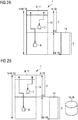
- FIG. 2B shows a schematic representation of a second conceivable embodiment of a memory architecture. It is the Main memory 1 in the in FIG. 2A constructed manner shown. However, unlike the architecture is off FIG. 2A in FIG. 2B
- a hard disk 15 is provided on the program data according to a third data type 16, for example, with a lower compared to the above data types 7 and 8 access frequency (cold data) can be stored.
- the hard disk memory 15 has a longer access time compared to the memories 2, 14 and 3, 10.
- a program 6 can also advantageously access the hard disk memory 15, which is not shown for the sake of simplicity.
- FIG. 2B Thus, three different memories 10, 14, 15 for different data types 7, 8, 16 can be distinguished.
- the memories 10 and 14 are used as hybrid data.
- Main memory 1 (as well as in FIG. 2A ) summarized.
- Figure 2C shows a schematic representation of an architecture according to the invention in a computer system, wherein, similar to in FIG. 1 , a main memory 1, an operating system level 4 and a user level 5 is set up.
- the main memory 1 exhibits according to the architectures FIGS. 2A and 2B a first memory 14 according to a first memory type 2 and a second, extended memory 10 according to a second memory type 3.
- a running application program 6 is provided at user level 5, which by means of operating system level 4, in particular by means of a memory management unit 9 at operating system level 4, to main memory 1, specifically either to first memory 14 according to first memory type 2 or to extended memory 10 according to the second memory type 3, can access.
- a first interface 13a and a second interface 13b are set up in the program 6.
- the program 6 can address the first memory 14 according to the first memory type 2 via the first program interface 13a, while the program 6 can address the extended memory 10 according to the second memory type 3 in the main memory 1 via the program interface 13b.
- the program interfaces 13a and 13b may include, in addition to memory instructions, also program interfaces for allocating an allocation of a respective memory.
- program interface 13a may be a routine "m1alloc ()"
- program interface 13b may include a routine "m2alloc ()".
- different memories 14, 10 of a first and second type 2, 3 can be addressed by different allocation instructions for a corresponding access for storing different types of data.
- the program 6 can acquire information about the access behavior of the different memories 14, 10 and possibly 15 and / or record information about the access frequency to the respective program data 11. This can be done statically or dynamically. Based on the information collected, a decision can then be made about selecting the appropriate memory in the application program.
- FIGS. 1 . 2A . 2 B and 2C represent only exemplary embodiments of possible architectures of the illustrated computer system or possible operations of the described method.
Description
- Die Erfindung betrifft ein Verfahren zum verbesserten Zugriff auf einen Hauptspeicher eines Computersystems, ein solches Computersystem sowie ein Computerprogramm-Produkt, welches eingerichtet ist auf einem entsprechenden Computersystem ausgeführt zu werden und bei dessen Ausführung ein entsprechendes Verfahren durchführt.
- Seit jeher besteht in der Computertechnologie eine Schwierigkeit darin, dass Computerprogramme bei ihrer Ausführung Zugriff auf Hauptspeicher eines Computersystems beanspruchen, was oftmals zu Speicherknappheit im Hauptspeicher führen kann. Daraus können zum Teil gravierende Zugriffszeitverzögerungen resultieren, welche sich in einer (z.T. gravierenden) Ausdehnung der Zeitdauer für die Prozessabarbeitung innerhalb eines Computersystems äußeren.
- Gerade bei dem so genannten In-Memory-Computing, das heißt bei einer reinen Abarbeitung von Programmdaten innerhalb des Hauptspeichers eines Computersystems, äußern sich derartige Zeitverzögerungen zum Beispiel bei Datenbank-Management-Systemen, weil große Teile der Datenbank oder die gesamte Datenbank im Hauptspeicher abgelegt ist. Oftmals übersteigt der Bedarf an Speicherplatz für die Datenbank den physisch zur Verfügung gestellten Speicherplatz deutlich.
- Bisherige Ansätze zur Vermeidung von Hauptspeicherknappheit und Zeitverzögerung der obigen Art sehen vor, Programmdaten auf unterschiedliche Speicherhierarchien aufzuteilen. So können Programmdaten beispielsweise aus dem Hauptspeicher in einen Backup-Speicher, beispielsweise auf Festplatte, ausgelagert werden (Swap Storage).
Derartige Ansätze haben den Nachteil, dass kostbarer Speicherplatz im Hauptspeicher dennoch von laufenden Programmen kontinuierlich beansprucht wird, so dass einer Zeitverzögerung beziehungsweise Speicherknappheit im Hauptspeicher nur begrenzt entgegengewirkt werden kann. So entstehen Zeitverzögerungen bei Ausführung von Programmdaten beispielsweise dadurch, dass durch eine übergeordnete Speicher-Management-Einheit Programmdaten zwischen dem Hauptspeicher und einem Backup-Speicher (Swap Storage, Systemplatte oder Festplatte) hin und her geschoben werden müssen. -
WO2013/016723 ,US2008/291727 undWO2008/131058 offenbaren Speicher mit unterschiedlichen Speichertypen. - Die Aufgabe der vorliegenden Erfindung besteht somit darin, den Zugriff auf einen Hauptspeicher eines Computersystems derart zu verbessern, dass eine Hauptspeicherknappheit und Zeitverzögerung von vorneherein minimiert beziehungsweise gänzlich unterbunden werden können, was zu einer schnelleren Abarbeitung von Prozessen in Computersystemen führt.
Diese Aufgabe wird in einem ersten Aspekt durch ein Verfahren nach Anspruch 1 gelöst.
Gemäß diesem Verfahren wird ein Hauptspeicher aus wenigstens einem ersten Speicher gemäß einem ersten Speichertypus und einem zweiten Speicher gemäß einem zweiten Speichertypus bereitgestellt, wobei für einen Zugriff auf den Hauptspeicher eine Auswahlmöglichkeit zwischen dem ersten Speicher und dem zweiten Speicher bereitgestellt wird, und wobei vermittels der Auswahlmöglichkeit in Abhängigkeit vom jeweiligen Zugriffsverhalten des ersten Speichers und des zweiten Speichers zwischen einem Zugriff auf den ersten Speicher und einem Zugriff auf den zweiten Speicher unterschieden wird. Vorteilhaft wird bei dem Verfahren die Auswahlmöglichkeit durch ein laufendes Anwendungsprogramm bereitgestellt. - Der Begriff "Anwendungsprogramm" soll in diesem Kontext verstanden werden als jegliches Anwendungsprogramm, welches in einem Computersystem auf Softwareebene ablaufen kann. Der Begriff umfasst auch lediglich entsprechende Programmteile (so genannte Routinen) eines Anwendungsprogramms.
- Der Begriff "Hauptspeicher" soll in diesem Kontext verstanden werden als Kurzzeitspeicher, in den Programme oder Programmteile und die dafür benötigten Programmdaten für und während einer Ausführung innerhalb eines Computersystems geladen werden. Der Hauptspeicher wird oftmals auch als Arbeitsspeicher bezeichnet. Der Hauptspeicher unterscheidet sich somit grundlegend in seiner Speicherhierarchie von weiteren Speicherebenen innerhalb eines Computersystems, wie zum Beispiel Festplattenspeicher oder Bandlaufwerkspeicher, welche im Gegensatz zum Hauptspeicher als Langzeitspeicher zur Datenvorhaltung eingesetzt werden.
- Der Begriff "Zugriffsverhalten" beschreibt in diesem Kontext intrinsische Eigenschaften der Speicher des jeweiligen Typus. Das jeweilige Zugriffsverhalten des ersten Speichers und des zweiten Speichers wird beispielsweise wenigstens anhand der folgenden Eigenschaften bestimmt:
- Speicherzugriffszeit,
- Speicherzykluszeit,
- Latenzzeit,
- Datendurchsatz.
- Das Verfahren der vorliegenden Art hat den generellen Vorteil gegenüber herkömmlichen Ansätzen, dass je nach Anforderung zwischen unterschiedlichen Speichertypen im Hauptspeicher gewählt werden kann. Der Hauptspeicher kann von einem ersten Speichertypus auf einen zusätzlichen zweiten Speichertypus erweitert beziehungsweise vergrößert werden, wobei eine bessere Auslastung des jeweiligen Speichers in Abhängigkeit von intrinsischen Eigenschaften des jeweiligen Speichers gewährleistet ist. Somit stellt das erläuterte Verfahren eine Kombination aus einer Vergrößerung eines Hauptspeichers in einem Computersystem um einen zweiten Speicher und einer Auswahlmöglichkeit eines Zugriffs auf den jeweiligen Speicher in Abhängigkeit vom entsprechenden Zugriffsverhalten des jeweiligen Speichers bereit. Auf diese Weise wird durch das Verfahren ein Hybrid-Hauptspeicher bereitgestellt.
- Vermittels der Auswahlmöglichkeit kann somit im Vorhinein, das heißt vor Beanspruchung des jeweiligen Speichertypus im Hauptspeicher, unterschieden werden, welcher Speichertypus des Hauptspeichers für einen entsprechenden Prozess geeignet beziehungsweise frei ist. Auf diese Weise wird verhindert, dass ein herkömmlicher Hauptspeicher zunächst vollständig mit Daten belegt wird, regelrecht vollgestopft wird, und erst im Nachhinein beispielsweise durch eine Speicher-Management-Einheit entschieden wird, welche Daten für einen häufigen Zugriff im Hauptspeicher belassen werden und welche Daten in eine Auslagerungsdatei auf einen Backup-Speicher (Swap Storage, Systemplatte oder Festplatte) ausgelagert werden.
- Das Verfahren der erläuterten Art verbessert somit den Zugriff (Hauptspeichervergrößerung, Zugriffszeitminimierung) auf einen Hauptspeicher eines Computersystems, indem Ressourcen des Hauptspeichers in mehrere Speicher unterschiedlichen Speichertyps aufgesplittet und vorbereitet werden, wobei vor Belegung eines entsprechenden Speichers durch die Auswahlmöglichkeit ein Zugriff auf den entsprechenden Speicher unterschieden wird.
- Aufgrund der durch ein laufendes Anwendungsprogramm bereitgestellten Auswahlmöglichkeit kann ein laufendes Anwendungsprogramm selbst zwischen den durch den Hauptspeicher bereitgestellten Speichertypen auswählen und den für jeweilige Daten bzw. Datentypen jeweils geeigneten Speicher des Hauptspeichers ansprechen.
- Bevorzugt sind bei dem erläuterten Verfahren im Anwendungsprogramm wenigstens zwei Programm-Schnittstellen vorgesehen. Über eine erste Programm-Schnittstelle wird der erste Speicher angesprochen, während über eine zweite Programm-Schnittstelle der zweite Speicher angesprochen wird. Somit kann ein laufendes Anwendungsprogramm vermittels der unterschiedlichen Schnittstellen zum Beispiel für unterschiedliche Zugriffshäufigkeiten auf jeweilige Programmdaten unterschiedliche Speicher des Hauptspeichers auswählen, allokieren und ansprechen. Dazu können beispielsweise unterschiedliche Programm-Routinen aufgerufen werden.
- Bevorzugt werden bei dem Verfahren der erläuterten Art Programmdaten des im Computersystem laufenden Anwendungsprogramms vermittels der Auswahlmöglichkeit in Abhängigkeit vom jeweiligen Zugriffsverhalten des ersten Speichers und des zweiten Speichers und/oder in Abhängigkeit von der Zugriffshäufigkeit auf die jeweiligen Programmdaten entweder im ersten Speicher oder im zweiten Speicher abgelegt. Eine derartige Maßnahme hat den Vorteil, dass zwischen der Zugriffshäufigkeit jeweiliger Programmdaten unterschieden werden kann.
- Programmdaten mit einer hohen Zugriffshäufigkeit werden als sogenannte "hot data" bezeichnet, während Programmdaten mit einer mittleren Zugriffshäufigkeit als "warm Data" und Programmdaten mit einer niedrigen Zugriffshäufigkeit als "cold Data" bezeichnet werden. Eine Unterscheidung des Speicherzugriffs in Abhängigkeit vom oben erläuterten Zugriffsverhalten des jeweiligen ersten oder zweiten Speichers und/oder in Abhängigkeit von der Zugriffshäufigkeit auf die jeweiligen Programmdaten ermöglicht eine verbesserte Ausnutzung verschiedener Speichertypen, die für verschiedene Zugriffshäufigkeiten auf Programmdaten geeignet beziehungsweise ausgelegt sind.
- Beispielsweise ist ein Speicher mit einer niedrigen Speicherzugriffszeit geeignet für einen häufigen Speicherzugriff, während ein Speicher mit einer längeren Speicherzugriffszeit vielmehr für Zugriffe von niedrigerer Häufigkeit geeignet ist. Beispielsweise können in einem Datenbank-Management-System Transaktionsdaten, auf die häufig zugegriffen wird (hot data), in einem Speicher des Hauptspeichers mit einem schnellen Speicherzugriff abgelegt werden, während Daten für einen gewöhnlichen Tabellenbeziehungsweise Verzeichniszugriff, auf die weniger häufig zugegriffen wird (warm data), in einem Speicher des Hauptspeichers mit einer höheren Speicherzugriffszeit abgelegt werden.
- Durch die Unterscheidung wird ein für eine spezifische Zugriffshäufigkeit weniger geeigneter Speicher nicht unnötig belegt, sondern vorab durch ein laufendes Anwendungsprogramm eine Auswahl des geeigneteren Speichers vermittels des erläuterten Verfahrens getroffen.
- Eine Ermittlung des Zugriffsverhaltens des ersten Speichers und des zweiten Speichers bzw. eine Ermittlung der Zugriffshäufigkeit auf die jeweiligen Programmdaten kann vermittels eines speziellen Algorithmus im laufenden Anwendungsprogramm statisch und/oder dynamisch durchgeführt werden. Beispielsweise können dem Anwendungsprogramm durch ein Betriebssystem, ggf. iterativ, bestimmte Parameter und/oder Variablenwerte übergeben werden, die ein Zugriffsverhalten des ersten Speichers und des zweiten Speichers widerspiegeln und im Programm entsprechende Berücksichtigung für eine Auswahl des geeigneten Speichers finden. Ferner kann für eine derartige Auswahl auch eine Zugriffshäufigkeit auf die jeweiligen Programmdaten anhand eines Betriebsverhaltens des Anwendungsprogramms, des Betriebssystems und/oder sonstiger Komponenten des Computersystems, unter Umständen iterativ, ermittelt werden. Vorteilhaft laufen die Prozesse zur Ermittlung dieser Informationen automatisiert im Anwendungsprogramm ab. Aufgrund der gesammelten Informationen kann dann eine Entscheidung über die Auswahl des geeigneten Speichers im Anwendungsprogramm getroffen werden.
- Vorteilhaft wird bei dem Verfahren der erläuterten Art der erste Speicher als flüchtiger Speichertypus bereitgestellt und der zweite Speicher als nicht flüchtiger Speichertypus bereitgestellt. Beispielsweise ist der erste Speicher vom Typus DRAM (Dynamic Random Access Memory), während der zweite Speicher vom Speichertypus NVRAM (Non-Volatile Random-Access Memory) ist. Alternativ ist denkbar, auch den zweiten Speicher als flüchtigen Speichertypus, z.B. DRAM, bereitzustellen.
- Beispielsweise kann der zweite Speicher, im Falle eines nicht flüchtigen Speichers vom Typus NVRAM, als SSD-Speicher (Solid-State-Drive) eingerichtet sein. Andere Speichertypen sind ebenfalls denkbar und nicht durch das vorliegende Verfahren ausgeschlossen. Der zweite Speicher kann als lokales Speichermedium innerhalb des Computersystems oder entfernt (Remote) über Netzwerk eingebunden sein.
- Ein Vorteil der Einrichtung des ersten und zweiten Speichers gemäß der erläuterten Art besteht in der Kombination von Speichertypen mit unterschiedlichen Zugriffs-/Speichereigenschaften (flüchtig/nicht flüchtig, Zugriffszeiten, Kosten, und so weiter). So können Daten, die im Hauptspeicher abzulegen sind, in Abhängigkeit von ihren entsprechenden Eigenschaften (zum Beispiel hot/warm/cold data) und in Abhängigkeit vom jeweiligen Zugriffsverhalten des ersten beziehungsweise zweiten Speichers entweder in einem flüchtigen oder in einem nicht flüchtigen Speicherbereich des Hauptspeichers abgelegt werden. Dies kann zum Beispiel in Abhängigkeit von entsprechenden Zugriffszeiten, Auslastung, Bereitstellung im Hinblick auf Speicherkosten, und so weiter erfolgen. Auch in diesem Aspekt werden somit Stärken des beschriebenen Hybrid-Hauptspeichers in Verbindung mit dem erläuterten Verfahren augenscheinlich.
- Alternativ oder ergänzend zu den erläuterten Speichertypen kann wenigstens ein Speicher (zum Beispiel der zweite Speicher anstelle des Typus NVRAM/SSD) auch gemäß dem zukünftig eingesetzten so genannten "Storage Class Memory"-Typus (SCM) eingerichtet werden. SCM-Speicher erlauben eine Kombination von Vorzügen klassischer Kurzzeit(-Haupt)speicher mit den Vorzügen klassischer Langzeitspeicher.
- Vorzugsweise erfolgt bei dem erläuterten Verfahren ein Zugriff auf den Hauptspeicher Byte- oder Wort-weise. Auf diese Weise kann ein Vorteil einer raschen Schreib-/Lese-Zugriffszeit mit den weiteren Vorteilen des erläuterten Verfahrens kombiniert werden.
- In einem weiteren Aspekt wird die obige Aufgabe durch ein Computersystem gelöst, umfassend einen Hauptspeicher, wobei der Hauptspeicher wenigstens einen ersten Speicher gemäß einem ersten Speichertypus und einen zweiten Speicher gemäß einem zweiten Speichertypus aufweist, wobei für einen Zugriff auf den Hauptspeicher eine Auswahlmöglichkeit zwischen dem ersten Speicher und dem zweiten Speicher eingerichtet ist derart, dass vermittels der Auswahlmöglichkeit ein Zugriff auf den ersten Speicher und ein Zugriff auf den zweiten Speicher in Abhängigkeit vom jeweiligen Zugriffsverhalten des ersten Speichers und des zweiten Speichers unterscheidbar sind, und wobei die Auswahlmöglichkeit in einem Anwendungsprogramm implementiert ist.
- Bei einem derartigen Computersystem ist der Hauptspeicher neben einem Speicher gemäß einem ersten Speichertypus um einen Speicher gemäß einem zweiten Speichertypus erweitert beziehungsweise vergrößert. Vermittels der in einem Anwendungsprogramm eingerichteten bzw. implementierten Auswahlmöglichkeit ist eine Funktionalität bereitgestellt, um je nach Anforderung zwischen unterschiedlichen Speichertypen im Hauptspeicher zu wählen. Auf diese Weise ist eine bessere Auslastung des Hauptspeichers in Abhängigkeit von intrinsischen Eigenschaften des jeweiligen Speichers gewährleistet.
- Sämtliche Maßnahmen und Verfahrensschritte des oben erläuterten Verfahrens sowie deren Vorteile und vorteilhafte Aspekte sind auch auf ein Computersystem der erläuterten Art anwendbar und umgekehrt. Das bedeutet, dass das Computersystem vorteilhaft dazu eingerichtet ist, ein Verfahren der oben erläuterten Art mit sämtlichen Vorteilen beziehungsweise vorteilhaften Aspekten und Verfahrensschritten beziehungsweise Maßnahmen bereitzustellen und durchzuführen.
- Gemäß einem weiteren Aspekt wird ein Computerprogramm-Produkt vorgeschlagen, welches eingerichtet ist auf einem Computersystem ausgeführt zu werden und bei dessen Ausführung ein Verfahren der erläuterten Art durchführt.
- Weitere vorteilhafte Ausgestaltungen des erläuterten Verfahrens sowie des erläuterten Computersystems sind in den Unteransprüchen offenbart. Die Erfindung wird anhand mehrerer Zeichnungen im Weiteren näher erläutert.
- Es zeigen:
-
Figur 1 eine schematisierte Darstellung mehrerer Hierarchien in einem Computersystem, -
Figur 2A eine schematisierte Darstellung einer ersten Ausführung einer erfindungsgemäßen Speicherarchitektur, -
Figur 2B eine schematisierte Darstellung einer zweiten Ausführung einer erfindungsgemäßen Speicherarchitektur und -
Figur 2C eine schematisierte Darstellung mehrerer Hierarchien in einem Computersystem zur Durchführung eines erfindungsgemäßen Verfahrens. -
Figur 1 zeigt eine schematisierte Darstellung mehrerer Hierarchien innerhalb einer Computersystem-Architektur. Die Architektur umfasst einen Hauptspeicher 1, eine Betriebssystemebene 4 sowie eine Benutzerebene 5. - Der Hauptspeicher 1 umfasst einen Speicher 14 gemäß einem ersten Speichertypus 2, welcher beispielsweise als DRAM-Speicher ausgeführt ist. Der Hauptspeicher 1 dient als Arbeitsspeicher zur Verarbeitung von Programm- sowie sonstigen Prozessdaten innerhalb des Computersystems. Somit unterscheidet sich der Hauptspeicher 1 grundsätzlich von einem Langzeitspeicher, wie zum Beispiel Festplatten oder Bandlaufwerke, welche zur Langzeitdatenspeicherung in Computersystemen eingesetzt werden, jedoch der Einfachheit halber in
Figur 1 nicht dargestellt sind. - Die Betriebssystemebene 4 umfasst eine Betriebssystemumgebung, welche die Basisfunktionalität des Computersystems steuert und auf den Hauptspeicher 1 zugreifen kann. Insbesondere weist die Betriebssystemebene 4 eine Speicherverwaltungseinheit beziehungsweise Speicher-Management-Einheit 9 auf, die auf den Hauptspeicher 1 zugreifen kann, um beispielsweise Daten in den Hauptspeicher 1 zu schreiben oder aus dem Hauptspeicher 1 auszulesen oder einen Speicherbereich des Hauptspeichers 1 vorbestimmten Programmen im Computersystem für einen Speicherzugriff zuzuweisen (so genannte Speicherallokation). Die Betriebssystemebene 4 kann rein software-basiert aufgebaut sein oder eine Kombination aus Software- und Hardware-Bausteinen umfassen. Beispielsweise kann die Betriebssystemebene 4 eine Betriebssystem-Software aufweisen. Die Speicherverwaltungseinheit 9 kann software-basiert oder entsprechend gemischt aus Hardware und Software aufgebaut sein.
- Auf einer Benutzerebene 5, welche in
Figur 1 hierarchisch als oberste Ebene dargestellt ist, findet sich ein Programm 6, welches als laufendes Programm Programmdaten verarbeitet und als Anwendungsprogramm vorbestimmte Anwendungen realisiert. Hierzu liegen im Programm 6 Programmdaten 11 vor beziehungsweise werden im Programm 6 Programmdaten 11 während des Ablaufs erzeugt, welche über eine Programmschnittstelle 12 vermittels der Speicherverwaltungseinheit 9 der Betriebssystemebene 4 an den Hauptspeicher 1, konkret den ersten Speicher 14 gemäß dem ersten Speichertypus 2, übergeben werden können. - Vermittels der Programmschnittstelle 12 kann das Programm 6 somit beispielsweise über die Speicherverwaltungseinheit 9 einen bestimmten Speicherbereich im Hauptspeicher 1 zur Ablage von Programmdaten 11 ausnutzen, wobei der entsprechende Speicherbereich zuvor entweder über das Programm 6 selbst oder über die Speicherverwaltungseinheit 9 der Betriebssystemebene 4 reserviert (allokiert) wurde.
- Bei der Architektur gemäß
Figur 1 ist somit ein Programm 6 (oder mehrere laufende Programme 6, welche der Einfachheit halber inFigur 1 nicht dargestellt sind) grundsätzlich bestrebt, möglichst viel Speicher im Hauptspeicher 1 für sich ausnutzen zu können. Dabei kann es vorkommen, dass in einem Betrieb des Computersystems nahezu jeglicher Speicher des Hauptspeichers 1 mit entsprechenden Programmdaten 11 belegt ist, so dass es zu einer Knappheit an Speicherressourcen im Hauptspeicher 1 kommt. Andere Programme, welche ebenfalls auf die Speicherressourcen des Hauptspeichers 1 zugreifen wollen, sind dann entweder blockiert oder können Speicher des Hauptspeichers 1 erst ausnutzen, wenn andere Daten aus dem Hauptspeicher 1 entfernt wurden (zum Beispiel durch Auslagerung in eine spezielle Partition beziehungsweise einen Backup-Speicher, so genannter Swap-Speicher). - Bei einer Architektur gemäß
Figur 1 kann es somit zu Zugriffszeitverzögerungen und Speicherknappheit auf dem Hauptspeicher 1 kommen, was sich in einer schlechten Performance des Computersystems niederschlägt. - Zur Lösung derartiger Nachteile ist gemäß einer schematisierten ersten Ausführung eines Hauptspeichers 1 gemäß
Figur 2A vorgeschlagen, den Hauptspeicher 1 neben einem Speicher 14 gemäß einem ersten Speichertypus 2 um einen zweiten Speicher 10 gemäß einem zweiten Speichertypus 3 zu erweitern und zu vergrößern. Das bedeutet, dass der Hauptspeicher 1 gemäßFigur 2A um einen erweiterten Speicher 10 gegenüber dem Hauptspeicher 1 gemäß einer Architektur ausFigur 1 ergänzt ist, so dass ein Programm 6 beziehungsweise Programmdaten 11 eines laufenden Programms 6 sowohl auf den ersten Speicher 14 gemäß dem ersten Speichertypus 2 als auch auf den zweiten, erweiterten Speicher 10 gemäß einem zweiten Speichertypus 3 zugreifen können. - Im Programm 6 ist hierzu eine Auswahlmöglichkeit implementiert, um Programmdaten 11 eines ersten Datentypus 7 im Speicher 14 gemäß dem ersten Speichertypus 2 abzulegen beziehungsweise Programmdaten 11 gemäß einem zweiten Datentypus 8 im zweiten Speicher 10 gemäß dem zweiten Speichertypus 3 abzulegen. Ein Programm 6 kann vermittels der Auswahlmöglichkeit somit vorab entscheiden, auf welchen Speicher 2, 14 beziehungsweise 3, 10 des Hauptspeichers 1 es zugreifen möchte. Insbesondere erfolgt eine Auswahl in Abhängigkeit von Zugriffseigenschaften der Speicher 10, 14 gemäß dem ersten Speichertypus 2 und gemäß zweiten Speichertypus 3. Derartige Zugriffseigenschaften bestimmten sich vorteilhaft aus der Speicherzugriffszeit, der Speicherzykluszeit, einer Latenzzeit oder durch den Datendurchsatz. Weitere intrinsische Eigenschaften der Speicher 2 und 3 können gleichfalls herangezogen werden.
- Beispielsweise können Programmdaten 11 gemäß dem ersten Datentypus 7 Daten mit einer hohen Zugriffshäufigkeit (so genannte hot data) umfassen, wobei vorteilhaft der erste Speicher 14 gemäß dem ersten Speichertypus 2 als schneller Speicher mit einer kurzen Zugriffszeit ausgeführt ist.
- Programmdaten 11 gemäß dem zweiten Datentypus 8 können beispielsweise Programmdaten mit einer geringeren Zugriffshäufigkeit (warm data) sein, welche vermittels des Programms 6 vorteilhaft im erweiterten Speicher 10 gemäß dem zweiten Speichertypus 3 abgelegt werden. Der erweiterte Speicher 10 kann somit im Vergleich zum ersten Speicher 14 ein langsamerer Speicher mit einer längeren Zugriffszeit sein.
- Auf diese Weise kann ein Programm 6 in Abhängigkeit von Zugriffseigenschaften der jeweiligen Speicher 2, 14 und 3, 10 beziehungsweise in Abhängigkeit von Datentypen 7 und 8 der Programmdaten 11 (beispielsweise in Abhängigkeit von der Zugriffshäufigkeit auf Programmdaten 11) entscheiden, welcher der unterschiedlichen Speichertypen 2, 14 und 3, 10 des Hauptspeichers 1 beansprucht werden soll. Dies ermöglicht einem Programm 6 eine Vorabauswahl geeigneter Speichertypen für geeignete Datentypen der Programmdaten 11, so dass ein jeweiliger Speicher gemäß einem jeweiligen Speichertypus 2 und 3 des Hauptspeichers 1 nicht unnötig mit Programmdaten 11 belegt wird, welche an anderer Stelle, das heißt in einem Speicherbereich eines anderen Speichertypus des Hauptspeichers 1, geeigneter abgelegt sein können. Auf diese Weise ist nicht nur eine Erweiterung oder Vergrößerung des Hauptspeichers 1 möglich, sondern auch eine bessere Auslastung in Abhängigkeit von intrinsischen Eigenschaften des jeweiligen Speichers gemäß dem jeweiligen Speichertypus 2 oder 3.
- Gemäß
Figur 2A können somit zwei unterschiedliche Speicher 10, 14 für unterschiedliche Datentypen 7, 8 unterschieden werden. Ein schneller Speicher 14 mit kurzer Zugriffszeit für einen ersten Datentypus 7 und ein im Vergleich dazu langsamerer Speicher 10 mit längerer Zugriffszeit für einen zweiten Datentypus 8. Auf diese Weise ist ein Hybrid-Hauptspeicher 1 geschaffen. - Beispielsweise kann der erste Speicher 14 gemäß dem ersten Speichertypus 2 als DRAM-Speicher ausgeführt sein, während der erweiterte Speicher 10 gemäß dem zweiten Speichertypus 3 als nicht flüchtiger Speicher, zum Beispiel als NVRAM-Speicher, ausgeführt ist. Der NVRAM-Speicher kann beispielsweise als Solid-State Speicher (SSD) ausgeführt sein. Dabei ist denkbar, den SSD-Speicher lokal im Computersystem zu implementieren oder entfernt auf einem über Netzwerk erreichbaren Computersystem zu implementieren, so dass auf diesen Speicher über Netzwerk (Remote) zugegriffen werden kann. Alternativ oder ergänzend ist auch denkbar, in umgekehrter Weise auf den lokalen Hauptspeicher 1 von einem oder mehreren entfernten Servern aus zuzugreifen (Remote Zugriff).
- Es ist auch denkbar, einen Speicher gemäß einem Speichertypus nach dem so genannten Storage Class Memory (SCM) vorzusehen.
- Gemäß
Figur 2A weist der erste Speicher 14 gemäß dem ersten Speichertypus 2 eine Größe von N Terabyte auf, während der erweiterte Speicher 10 gemäß dem zweiten Speichertypus 3 eine Größe von M Terabyte aufweist. Insgesamt umfasst daher der Hauptspeicher 1 eine für ein Programm 6 sichtbare Größe von N + M Terabyte. Dies ist schematisiert inFigur 2A dargestellt. Der Hauptspeicher 1 ist somit als Hybrid-Hauptspeicher eingerichtet. - Die Architektur gemäß 2A bietet u.a. zwei Vorteile. Ein erster Vorteil ist dadurch gegeben, dass ein Hauptspeicher 1 von einem ersten Speicher 14 gemäß einem ersten Speichertypus 2 mit N Terabyte um M Terabyte eines erweiterten Speichers 10 gemäß einem zweiten Speichertypus 3 auf einen Gesamtspeicher von N + M Terabyte erweitert und vergrößert werden kann. Der zweite Vorteil besteht darin, dass zusätzlich ein Programm eine Auswahlmöglichkeit hat, um Daten in Abhängigkeit vom Datentypus und in Abhängigkeit von den intrinsischen Zugriffseigenschaften der jeweiligen Speicher entweder im ersten Speicher 14 oder im zweiten Speicher 10 abzulegen.
-
Figur 2B zeigt eine schematisierte Darstellung einer zweiten denkbaren Ausführung einer Speicherarchitektur. Dabei ist der Hauptspeicher 1 in der inFigur 2A gezeigten Weise aufgebaut. Allerdings ist im Unterschied zur Architektur ausFigur 2A inFigur 2B zusätzlich ein Festplattenspeicher 15 vorgesehen, auf dem Programmdaten gemäß einem dritten Datentypus 16, z.B. mit einer im Vergleich zu den obigen Datentypen 7 und 8 niedrigeren Zugriffshäufigkeit (cold data) abgelegt werden können. Der Festplattenspeicher 15 weist eine im Vergleich zu den Speichern 2, 14 und 3, 10 längere Zugriffszeit auf. Ein Programm 6 kann vorteilhaft auf den Festplattenspeicher 15 ebenfalls zugreifen, was der Einfachheit halber jedoch nicht dargestellt ist. - Gemäß
Figur 2B können somit drei unterschiedliche Speicher 10, 14, 15 für unterschiedliche Datentypen 7, 8, 16 unterschieden werden. Ein schneller Speicher 14 mit kurzer Zugriffszeit für einen ersten Datentypus 7, ein mittelschneller Speicher 10 mit mittlerer Zugriffszeit für einen zweiten Datentypus 8, sowie ein langsamer Speicher 15 mit langer Zugriffszeit für einen dritten Datentypus 16. Die Speicher 10 und 14 sind dabei als Hybrid-Hauptspeicher 1 (wie auch inFigur 2A ) zusammengefasst. -
Figur 2C zeigt eine schematisierte Darstellung einer erfindungsgemäßen Architektur in einem Computersystem, wobei, ähnlich wie inFigur 1 , ein Hauptspeicher 1, eine Betriebssystemebene 4 sowie eine Benutzerebene 5 eingerichtet ist. - Der Hauptspeicher 1 weist gemäß den Architekturen aus
Figur 2A und 2B einen ersten Speicher 14 gemäß einem ersten Speichertypus 2 und einen zweiten, erweiterten Speicher 10 gemäß einem zweiten Speichertypus 3 auf. - Wie bereits im Zusammenhang mit
Figur 1 erläutert, ist auf Benutzerebene 5 ein laufendes Anwendungsprogramm 6 vorgesehen, welches vermittels der Betriebssystemebene 4, insbesondere vermittels einer Speicherverwaltungseinheit 9 auf Betriebssystemebene 4, auf den Hauptspeicher 1, konkret entweder auf den ersten Speicher 14 gemäß dem ersten Speichertypus 2 oder auf den erweiterten Speicher 10 gemäß dem zweiten Speichertypus 3, zugreifen kann. - Für einen entsprechenden Zugriff und als Auswahlmöglichkeit für das Programm 6 sind im Programm 6 zwei Programmschnittstellen, eine erste Schnittstelle 13a und eine zweite Schnittstelle 13b, eingerichtet. Beispielsweise kann das Programm 6 über die erste Programmschnittstelle 13a den ersten Speicher 14 gemäß dem ersten Speichertypus 2 ansprechen, während das Programm 6 über die Programmschnittstelle 13b den erweiterten Speicher 10 gemäß dem zweiten Speichertypus 3 im Hauptspeicher 1 ansprechen kann. Die Programmschnittstellen 13a und 13b können neben Speicherbefehlen auch Programminterfaces zum Allokieren bzw. Anweisen eines Allokierens eines jeweiligen Speichers umfassen. Beispielsweise kann die Programmschnittstelle 13a eine Routine "m1alloc()" sein während die Programmschnittstelle 13b eine Routine "m2alloc()" umfasst. Auf diese Weise können unterschiedliche Speicher 14, 10 eines ersten und zweiten Typus 2, 3 durch unterschiedliche Allokierungsbefehle für einen entsprechenden Zugriff zum Ablegen unterschiedlicher Datentypen angesprochen werden.
- Wie bereits zu
Figur 2A erläutert, kann das Programm 6 gemäßFigur 2C vermittels der Programmschnittstellen 13a und 13b und gegebenenfalls vermittels der Speicherverwaltungseinheit 9 Programmdaten 11 in Abhängigkeit von ihrer Zugriffshäufigkeit und/oder in Abhängigkeit vom Zugriffsverhalten der jeweiligen Speicher entweder im ersten Speicher 14 gemäß dem ersten Speichertypus 2 oder im erweiterten Speicher 10 gemäß dem zweiten Speichertypus 3 ablegen. Dies erfolgt analog zu den Erläuterungen gemäßFigur 2A . - Daneben ist auch denkbar, Programmdaten 11 in einem Festplattenspeicher 15 gemäß
Figur 2B abzulegen. Dies ist der Einfachheit halber jedoch nicht dargestellt. - Durch einen im Programm 6 vorteilhaft implementiereten Algorithmus, welcher automatisiert abläuft, kann das Programm 6 Informationen über das Zugriffsverhalten der unterschiedlichen Speicher 14, 10 und ggf. 15 erfassen und/oder Informationen über die Zugriffshäufigkeit auf die jeweiligen Programmdaten 11 erfassen. Dies kann statisch oder dynamisch erfolgen. Aufgrund der gesammelten Informationen kann dann eine Entscheidung über die Auswahl des geeigneten Speichers im Anwendungsprogramm getroffen werden.
- Die Zeichnungen gemäß den
Figuren 1 ,2A ,2B und2C stellen lediglich beispielhafte Ausführungen möglicher Architekturen des erläuterten Computersystems oder möglicher Abläufe des erläuterten Verfahrens dar. -
- 1
- Hauptspeicher
- 2
- erster Speichertypus
- 3
- zweiter Speichertypus
- 4
- Betriebssystemebene
- 5
- Benutzerebene
- 6
- Programm
- 7
- Daten gemäß einem ersten Datentypus
- 8
- Daten gemäß einem zweiten Datentypus
- 9
- Speicherverwaltungseinheit
- 10
- erweiterter zweiter Speicher
- 11
- Programmdaten
- 12
- Programmschnittstelle
- 13a, 13b
- Programmschnittstelle
- 14
- erster Speicher
- 15
- Festplattenspeicher
- 16
- Daten gemäß einem dritten Datentypus
Claims (11)
- Verfahren zum verbesserten Zugriff auf einen Hauptspeicher (1) eines Computersystems,- wobei ein Hauptspeicher (1) aus wenigstens einem ersten Speicher (14) gemäß einem ersten Speichertypus (2) und einem zweiten Speicher (10) gemäß einem zweiten Speichertypus (3) bereitgestellt wird, und- wobei für einen Zugriff auf den Hauptspeicher (1) eine Auswahlmöglichkeit zwischen dem ersten Speicher (14) und dem zweiten Speicher (10) bereitgestellt wird, und- wobei vermittels der Auswahlmöglichkeit in Abhängigkeit vom jeweiligen Zugriffsverhalten des ersten Speichers (14) und des zweiten Speichers (10) zwischen einem Zugriff auf den ersten Speicher (14) und einem Zugriff auf den zweiten Speicher (10) unterschieden wird, dadurch gekennzeichnet dass- die Auswahlmöglichkeit in einem laufenden Anwendungsprogramm (6) auf einer Benutzerebene (5) innerhalb einer Computersystem-Architektur implementiert ist und sich die Benutzerebene (5) von einer Betriebssystemebene (4) der Computersystem-Architektur unterscheidet, und- wobei das Anwendungsprogramm (6) vermittels der Auswahlmöglichkeit vorab entscheidet, auf welchen Speicher (10, 14) des Hauptspeichers (1) es zugreifen möchte.
- Verfahren nach Anspruch 1, wobei im Anwendungsprogramm (6) wenigstens zwei Programm-Schnittstellen (13a, 13b) vorgesehen sind und über die erste Programm-Schnittstelle (13a) der erste Speicher (14) angesprochen wird und über die zweite Programm-Schnittstelle (13b) der zweite Speicher (10) angesprochen wird.
- Verfahren nach Anspruch 1 oder 2, wobei Programmdaten (11) des im Computersystem laufenden Anwendungsprogramms (6) vermittels der Auswahlmöglichkeit in Abhängigkeit vom jeweiligen Zugriffsverhalten des ersten Speichers (14) und des zweiten Speichers (10) und/oder in Abhängigkeit von der Zugriffshäufigkeit auf die jeweiligen Programmdaten (11) entweder im ersten Speicher (14) oder im zweiten Speicher (10) abgelegt werden.
- Verfahren nach einem der Ansprüche 1 bis 3, wobei das jeweilige Zugriffsverhalten des ersten Speichers (14) und des zweiten Speichers (10) wenigstens anhand der folgenden Eigenschaften bestimmt wird:- Speicherzugriffszeit,- Speicherzykluszeit,- Latenzzeit,- Datendurchsatz.
- Verfahren nach einem der Ansprüche 1 bis 4, wobei der erste Speicher (14) als flüchtiger Speichertypus bereitgestellt wird und der zweite Speicher (10) als flüchtiger oder nichtflüchtiger Speichertypus bereitgestellt wird.
- Verfahren nach einem der Ansprüche 1 bis 5, wobei der zweite Speicher (10) als entfernter Speicher über Netzwerk von einem oder mehreren entfernten Computersystemen bereitgestellt wird.
- Verfahren nach einem der Ansprüche 1 bis 6, wobei ein Zugriff auf den Hauptspeicher (1) Byte- oder Wort-weise erfolgt.
- Computersystem umfassend einen Hauptspeicher (1), wobei der Hauptspeicher (1) wenigstens einen ersten Speicher (14) gemäß einem ersten Speichertypus (2) und einen zweiten Speicher (10) gemäß einem zweiten Speichertypus (3) aufweist, wobei für einen Zugriff auf den Hauptspeicher (1) eine Auswahlmöglichkeit zwischen dem ersten Speicher (14) und dem zweiten Speicher (10) eingerichtet ist derart, dass vermittels der Auswahlmöglichkeit ein Zugriff auf den ersten Speicher (14) und ein Zugriff auf den zweiten Speicher (10) in Abhängigkeit vom jeweiligen Zugriffsverhalten des ersten Speichers (14) und des zweiten Speichers (10) unterscheidbar sind, dadurch gekennzeichnet dass
die Auswahlmöglichkeit in einem Anwendungsprogramm (6) auf einer Benutzerebene (5) innerhalb einer Computersystem-Architektur implementiert ist und sich die Benutzerebene (5) von einer Betriebssystemebene (4) der Computersystem-Architektur unterscheidet, und
wobei das Anwendungsprogramm (6) eingerichtet ist, vermittels der Auswahlmöglichkeit vorab zu entscheiden, auf welchen Speicher (10, 14) des Hauptspeichers (1) es zugreifen möchte. - Computersystem nach Anspruch 8, wobei im Anwendungsprogramm (6) wenigstens zwei Programm-Schnittstellen (13a, 13b) zum Zugriff auf den Hauptspeicher (1) implementiert sind und über die erste Programm-Schnittstelle (13a) der erste Speicher (14) ansprechbar ist und über die zweite Programm-Schnittstelle (13b) der zweite Speicher (10) ansprechbar ist.
- Computersystem nach Anspruch 8 oder 9, welches eingerichtet ist, ein Verfahren nach einem der Ansprüche 1 bis 7 durchzuführen.
- Computerprogramm-Produkt, welches eingerichtet ist auf einem Computersystem ausgeführt zu werden und bei dessen Ausführung ein Verfahren nach einem der Ansprüche 1 bis 7 durchführt.
Applications Claiming Priority (2)
| Application Number | Priority Date | Filing Date | Title |
|---|---|---|---|
| DE102014104980 | 2014-04-08 | ||
| PCT/EP2015/057250 WO2015155103A1 (de) | 2014-04-08 | 2015-04-01 | Verfahren zum verbesserten zugriff auf einen hauptspeicher eines computersystems, entsprechendes computersystem sowie computerprogramm-produkt |
Publications (2)
| Publication Number | Publication Date |
|---|---|
| EP3129891A1 EP3129891A1 (de) | 2017-02-15 |
| EP3129891B1 true EP3129891B1 (de) | 2018-12-12 |
Family
ID=52814103
Family Applications (1)
| Application Number | Title | Priority Date | Filing Date |
|---|---|---|---|
| EP15714484.1A Active EP3129891B1 (de) | 2014-04-08 | 2015-04-01 | Verfahren zum verbesserten zugriff auf einen hauptspeicher eines computersystems, entsprechendes computersystem sowie computerprogramm-produkt |
Country Status (3)
| Country | Link |
|---|---|
| US (1) | US10248329B2 (de) |
| EP (1) | EP3129891B1 (de) |
| WO (1) | WO2015155103A1 (de) |
Families Citing this family (3)
| Publication number | Priority date | Publication date | Assignee | Title |
|---|---|---|---|---|
| WO2021209265A1 (en) | 2020-04-14 | 2021-10-21 | Basf Se | Tricyclic pesticidal compounds |
| US11515891B2 (en) | 2020-12-22 | 2022-11-29 | Intel Corporation | Application of low-density parity-check codes with codeword segmentation |
| JP2022099948A (ja) * | 2020-12-23 | 2022-07-05 | 株式会社日立製作所 | ストレージシステムおよびストレージシステムにおけるデータ量削減方法 |
Family Cites Families (24)
| Publication number | Priority date | Publication date | Assignee | Title |
|---|---|---|---|---|
| US5848432A (en) * | 1993-08-05 | 1998-12-08 | Hitachi, Ltd. | Data processor with variable types of cache memories |
| JP4597829B2 (ja) * | 2005-09-27 | 2010-12-15 | パトレネラ キャピタル リミテッド, エルエルシー | メモリ |
| US20070147115A1 (en) | 2005-12-28 | 2007-06-28 | Fong-Long Lin | Unified memory and controller |
| TW200739349A (en) * | 2006-04-12 | 2007-10-16 | Giga Byte Tech Co Ltd | Volatile storage device and serial connection type mixed storage device having the same |
| US8427891B2 (en) * | 2007-04-17 | 2013-04-23 | Rambus Inc. | Hybrid volatile and non-volatile memory device with a shared interface circuit |
| KR100909965B1 (ko) * | 2007-05-23 | 2009-07-29 | 삼성전자주식회사 | 버스를 공유하는 휘발성 메모리 및 불휘발성 메모리를구비하는 반도체 메모리 시스템 및 불휘발성 메모리의 동작제어 방법 |
| US8874831B2 (en) * | 2007-06-01 | 2014-10-28 | Netlist, Inc. | Flash-DRAM hybrid memory module |
| US8966580B2 (en) * | 2008-05-01 | 2015-02-24 | Sandisk Il Ltd. | System and method for copying protected data from one secured storage device to another via a third party |
| US10079048B2 (en) * | 2009-03-24 | 2018-09-18 | Western Digital Technologies, Inc. | Adjusting access of non-volatile semiconductor memory based on access time |
| US7948798B1 (en) * | 2009-07-22 | 2011-05-24 | Marvell International Ltd. | Mixed multi-level cell and single level cell storage device |
| US8478937B2 (en) * | 2009-09-30 | 2013-07-02 | Cleversafe, Inc. | Method and apparatus for dispersed storage memory device utilization |
| JP2011154547A (ja) * | 2010-01-27 | 2011-08-11 | Toshiba Corp | メモリ管理装置及びメモリ管理方法 |
| JP2012033047A (ja) * | 2010-07-30 | 2012-02-16 | Toshiba Corp | 情報処理装置、メモリ管理装置、メモリ管理方法、及びプログラム |
| US10048745B1 (en) * | 2010-09-30 | 2018-08-14 | The Directv Group, Inc. | Method and system for storing program guide data in a user device |
| TWI420309B (zh) * | 2010-11-12 | 2013-12-21 | Inventec Corp | 設定記憶體位址空間的方法 |
| US9454431B2 (en) * | 2010-11-29 | 2016-09-27 | International Business Machines Corporation | Memory selection for slice storage in a dispersed storage network |
| US9507534B2 (en) * | 2011-12-30 | 2016-11-29 | Intel Corporation | Home agent multi-level NVM memory architecture |
| US9734333B2 (en) * | 2012-04-17 | 2017-08-15 | Heat Software Usa Inc. | Information security techniques including detection, interdiction and/or mitigation of memory injection attacks |
| WO2014021779A1 (en) * | 2012-07-30 | 2014-02-06 | Agency For Science, Technology And Research | Servers and methods for controlling a server |
| US9224452B2 (en) * | 2013-01-17 | 2015-12-29 | Qualcomm Incorporated | Heterogeneous memory systems, and related methods and computer-readable media for supporting heterogeneous memory access requests in processor-based systems |
| US9037792B1 (en) * | 2013-06-06 | 2015-05-19 | Symantec Corporation | Systems and methods for providing caching for applications with solid-state storage devices |
| US9323457B2 (en) * | 2013-12-09 | 2016-04-26 | Xilinx, Inc. | Memory arrangement for implementation of high-throughput key-value stores |
| JP6118285B2 (ja) * | 2014-03-20 | 2017-04-19 | 株式会社東芝 | キャッシュメモリシステムおよびプロセッサシステム |
| US10152601B2 (en) * | 2014-06-05 | 2018-12-11 | International Business Machines Corporation | Reliably recovering stored data in a dispersed storage network |
-
2015
- 2015-04-01 EP EP15714484.1A patent/EP3129891B1/de active Active
- 2015-04-01 US US15/302,614 patent/US10248329B2/en active Active
- 2015-04-01 WO PCT/EP2015/057250 patent/WO2015155103A1/de active Application Filing
Non-Patent Citations (1)
| Title |
|---|
| None * |
Also Published As
| Publication number | Publication date |
|---|---|
| EP3129891A1 (de) | 2017-02-15 |
| WO2015155103A1 (de) | 2015-10-15 |
| US20170031608A1 (en) | 2017-02-02 |
| US10248329B2 (en) | 2019-04-02 |
Similar Documents
| Publication | Publication Date | Title |
|---|---|---|
| DE10211606B4 (de) | Datenverarbeitungseinrichtung mit einem Metadatensicherungsmanagement | |
| DE112010003662B4 (de) | Ausgleich nachlassender Funktionsfähigkeit von Halbleiterdatenträgern auf der Grundlage der von einer RAID-Steuereinheit empfangenen Daten- und Paritätsnutzungsinformationen | |
| DE112017005868T5 (de) | Verwaltung von e/a-abläufen für datenobjekte in einem speichersystem | |
| DE102013215535B4 (de) | Sicherung oder wiederherstellung von daten mit hilfe eines hauptspeichers und nichtflüchtiger speichermedien | |
| DE102008057219B4 (de) | Verfahren zum Betreiben eines Solid-State-Speichersystems, Solid-State-Speichersystem und Computersystem | |
| DE102012216022B4 (de) | Verwaltung einer Zeitpunktkopie-Beziehung für platzsparende Datenträger | |
| DE102012208141B4 (de) | Ausgleich nachlassender Funktionsfähigkeit | |
| EP2923261B1 (de) | VERFAHREN ZUR STEUERUNG EINES FLASH-SPEICHERS ZUR MASSENSPEICHERUNG, DER VON EINEM AN EINEN HOST ANSCHLIEßBAREN KOMMUNIKATIONSGERÄT UMFASST IST, UND COMPUTERPROGRAMMPRODUKT ZUR AUSFÜHRUNG DES VERFAHRENS | |
| DE112012002452T5 (de) | Anpassungsfähiges Zwischenspeichern von Datensätzen für Halbleiterplatten | |
| DE202010017613U1 (de) | Datenspeichervorrichtung mit host-gesteuerter Speicherbereinigung | |
| DE112019001480B4 (de) | Automatisches Optimieren der Ressourcennutzung in einemZieldatenbankverwaltungssystem zum Erhöhen der Arbeitslastleistung | |
| DE112009004503T5 (de) | Optimierung der zugriffszeit von auf speichern gespeicherten dateien | |
| DE112011105774B4 (de) | Verschiebbarer Speicher, der In-Memory-Datenstrukturen unterstützt | |
| DE112011102076T5 (de) | Neuordnen des Zugriffs zum Verringern der Gesamtsuchzeit auf Bandmedien | |
| WO2015090668A1 (de) | Posix-kompatibles dateisystem, verfahren zum erzeugen einer dateiliste und speichervorrichtung | |
| DE112012004571T5 (de) | Unterstützen von unvollständigen Datensegmenten in Flash-Cache-Speichern | |
| DE112020005695T5 (de) | Speichercontroller für solid-state-speichereinheiten | |
| EP3129891B1 (de) | Verfahren zum verbesserten zugriff auf einen hauptspeicher eines computersystems, entsprechendes computersystem sowie computerprogramm-produkt | |
| DE112015003888T5 (de) | Wiederaufnahme von Sitzungszuständen | |
| DE102012221814A1 (de) | Neuanordnung von Software-Abbildern auf der Grundlage von deren vorhergesagter Verwendung | |
| DE102018109929A1 (de) | NAND-Flash-Speichervorrichtung mit NAND-Puffer | |
| DE102020115969A1 (de) | Speichervorrichtungen, speichersysteme und verfahren zum betreiben von speichervorrichtungen | |
| DE112013000770B4 (de) | Höhere Auslagerungseffizienz | |
| DE112021006506T5 (de) | Verwaltung von Sperren-Koordinator-Rebalance in verteilten Dateisystemen | |
| EP3368975B1 (de) | Verfahren und vorrichtung zum beschleunigten ausführen von applikationen |
Legal Events
| Date | Code | Title | Description |
|---|---|---|---|
| STAA | Information on the status of an ep patent application or granted ep patent |
Free format text: STATUS: THE INTERNATIONAL PUBLICATION HAS BEEN MADE |
|
| PUAI | Public reference made under article 153(3) epc to a published international application that has entered the european phase |
Free format text: ORIGINAL CODE: 0009012 |
|
| STAA | Information on the status of an ep patent application or granted ep patent |
Free format text: STATUS: REQUEST FOR EXAMINATION WAS MADE |
|
| 17P | Request for examination filed |
Effective date: 20161007 |
|
| AK | Designated contracting states |
Kind code of ref document: A1 Designated state(s): AL AT BE BG CH CY CZ DE DK EE ES FI FR GB GR HR HU IE IS IT LI LT LU LV MC MK MT NL NO PL PT RO RS SE SI SK SM TR |
|
| AX | Request for extension of the european patent |
Extension state: BA ME |
|
| DAV | Request for validation of the european patent (deleted) | ||
| DAX | Request for extension of the european patent (deleted) | ||
| GRAP | Despatch of communication of intention to grant a patent |
Free format text: ORIGINAL CODE: EPIDOSNIGR1 |
|
| STAA | Information on the status of an ep patent application or granted ep patent |
Free format text: STATUS: GRANT OF PATENT IS INTENDED |
|
| INTG | Intention to grant announced |
Effective date: 20180817 |
|
| GRAS | Grant fee paid |
Free format text: ORIGINAL CODE: EPIDOSNIGR3 |
|
| GRAA | (expected) grant |
Free format text: ORIGINAL CODE: 0009210 |
|
| STAA | Information on the status of an ep patent application or granted ep patent |
Free format text: STATUS: THE PATENT HAS BEEN GRANTED |
|
| AK | Designated contracting states |
Kind code of ref document: B1 Designated state(s): AL AT BE BG CH CY CZ DE DK EE ES FI FR GB GR HR HU IE IS IT LI LT LU LV MC MK MT NL NO PL PT RO RS SE SI SK SM TR |
|
| REG | Reference to a national code |
Ref country code: GB Ref legal event code: FG4D Free format text: NOT ENGLISH |
|
| REG | Reference to a national code |
Ref country code: CH Ref legal event code: EP |
|
| REG | Reference to a national code |
Ref country code: AT Ref legal event code: REF Ref document number: 1076909 Country of ref document: AT Kind code of ref document: T Effective date: 20181215 |
|
| REG | Reference to a national code |
Ref country code: DE Ref legal event code: R096 Ref document number: 502015007195 Country of ref document: DE |
|
| REG | Reference to a national code |
Ref country code: IE Ref legal event code: FG4D Free format text: LANGUAGE OF EP DOCUMENT: GERMAN |
|
| REG | Reference to a national code |
Ref country code: NL Ref legal event code: MP Effective date: 20181212 |
|
| REG | Reference to a national code |
Ref country code: LT Ref legal event code: MG4D |
|
| PG25 | Lapsed in a contracting state [announced via postgrant information from national office to epo] |
Ref country code: FI Free format text: LAPSE BECAUSE OF FAILURE TO SUBMIT A TRANSLATION OF THE DESCRIPTION OR TO PAY THE FEE WITHIN THE PRESCRIBED TIME-LIMIT Effective date: 20181212 Ref country code: HR Free format text: LAPSE BECAUSE OF FAILURE TO SUBMIT A TRANSLATION OF THE DESCRIPTION OR TO PAY THE FEE WITHIN THE PRESCRIBED TIME-LIMIT Effective date: 20181212 Ref country code: LT Free format text: LAPSE BECAUSE OF FAILURE TO SUBMIT A TRANSLATION OF THE DESCRIPTION OR TO PAY THE FEE WITHIN THE PRESCRIBED TIME-LIMIT Effective date: 20181212 Ref country code: NO Free format text: LAPSE BECAUSE OF FAILURE TO SUBMIT A TRANSLATION OF THE DESCRIPTION OR TO PAY THE FEE WITHIN THE PRESCRIBED TIME-LIMIT Effective date: 20190312 Ref country code: LV Free format text: LAPSE BECAUSE OF FAILURE TO SUBMIT A TRANSLATION OF THE DESCRIPTION OR TO PAY THE FEE WITHIN THE PRESCRIBED TIME-LIMIT Effective date: 20181212 Ref country code: BG Free format text: LAPSE BECAUSE OF FAILURE TO SUBMIT A TRANSLATION OF THE DESCRIPTION OR TO PAY THE FEE WITHIN THE PRESCRIBED TIME-LIMIT Effective date: 20190312 Ref country code: ES Free format text: LAPSE BECAUSE OF FAILURE TO SUBMIT A TRANSLATION OF THE DESCRIPTION OR TO PAY THE FEE WITHIN THE PRESCRIBED TIME-LIMIT Effective date: 20181212 |
|
| PG25 | Lapsed in a contracting state [announced via postgrant information from national office to epo] |
Ref country code: AL Free format text: LAPSE BECAUSE OF FAILURE TO SUBMIT A TRANSLATION OF THE DESCRIPTION OR TO PAY THE FEE WITHIN THE PRESCRIBED TIME-LIMIT Effective date: 20181212 Ref country code: SE Free format text: LAPSE BECAUSE OF FAILURE TO SUBMIT A TRANSLATION OF THE DESCRIPTION OR TO PAY THE FEE WITHIN THE PRESCRIBED TIME-LIMIT Effective date: 20181212 Ref country code: GR Free format text: LAPSE BECAUSE OF FAILURE TO SUBMIT A TRANSLATION OF THE DESCRIPTION OR TO PAY THE FEE WITHIN THE PRESCRIBED TIME-LIMIT Effective date: 20190313 Ref country code: RS Free format text: LAPSE BECAUSE OF FAILURE TO SUBMIT A TRANSLATION OF THE DESCRIPTION OR TO PAY THE FEE WITHIN THE PRESCRIBED TIME-LIMIT Effective date: 20181212 |
|
| PG25 | Lapsed in a contracting state [announced via postgrant information from national office to epo] |
Ref country code: NL Free format text: LAPSE BECAUSE OF FAILURE TO SUBMIT A TRANSLATION OF THE DESCRIPTION OR TO PAY THE FEE WITHIN THE PRESCRIBED TIME-LIMIT Effective date: 20181212 |
|
| PG25 | Lapsed in a contracting state [announced via postgrant information from national office to epo] |
Ref country code: PT Free format text: LAPSE BECAUSE OF FAILURE TO SUBMIT A TRANSLATION OF THE DESCRIPTION OR TO PAY THE FEE WITHIN THE PRESCRIBED TIME-LIMIT Effective date: 20190412 Ref country code: CZ Free format text: LAPSE BECAUSE OF FAILURE TO SUBMIT A TRANSLATION OF THE DESCRIPTION OR TO PAY THE FEE WITHIN THE PRESCRIBED TIME-LIMIT Effective date: 20181212 Ref country code: PL Free format text: LAPSE BECAUSE OF FAILURE TO SUBMIT A TRANSLATION OF THE DESCRIPTION OR TO PAY THE FEE WITHIN THE PRESCRIBED TIME-LIMIT Effective date: 20181212 Ref country code: IT Free format text: LAPSE BECAUSE OF FAILURE TO SUBMIT A TRANSLATION OF THE DESCRIPTION OR TO PAY THE FEE WITHIN THE PRESCRIBED TIME-LIMIT Effective date: 20181212 |
|
| PG25 | Lapsed in a contracting state [announced via postgrant information from national office to epo] |
Ref country code: SM Free format text: LAPSE BECAUSE OF FAILURE TO SUBMIT A TRANSLATION OF THE DESCRIPTION OR TO PAY THE FEE WITHIN THE PRESCRIBED TIME-LIMIT Effective date: 20181212 Ref country code: EE Free format text: LAPSE BECAUSE OF FAILURE TO SUBMIT A TRANSLATION OF THE DESCRIPTION OR TO PAY THE FEE WITHIN THE PRESCRIBED TIME-LIMIT Effective date: 20181212 Ref country code: IS Free format text: LAPSE BECAUSE OF FAILURE TO SUBMIT A TRANSLATION OF THE DESCRIPTION OR TO PAY THE FEE WITHIN THE PRESCRIBED TIME-LIMIT Effective date: 20190412 Ref country code: SK Free format text: LAPSE BECAUSE OF FAILURE TO SUBMIT A TRANSLATION OF THE DESCRIPTION OR TO PAY THE FEE WITHIN THE PRESCRIBED TIME-LIMIT Effective date: 20181212 Ref country code: RO Free format text: LAPSE BECAUSE OF FAILURE TO SUBMIT A TRANSLATION OF THE DESCRIPTION OR TO PAY THE FEE WITHIN THE PRESCRIBED TIME-LIMIT Effective date: 20181212 |
|
| REG | Reference to a national code |
Ref country code: DE Ref legal event code: R097 Ref document number: 502015007195 Country of ref document: DE |
|
| PLBE | No opposition filed within time limit |
Free format text: ORIGINAL CODE: 0009261 |
|
| STAA | Information on the status of an ep patent application or granted ep patent |
Free format text: STATUS: NO OPPOSITION FILED WITHIN TIME LIMIT |
|
| PG25 | Lapsed in a contracting state [announced via postgrant information from national office to epo] |
Ref country code: DK Free format text: LAPSE BECAUSE OF FAILURE TO SUBMIT A TRANSLATION OF THE DESCRIPTION OR TO PAY THE FEE WITHIN THE PRESCRIBED TIME-LIMIT Effective date: 20181212 Ref country code: SI Free format text: LAPSE BECAUSE OF FAILURE TO SUBMIT A TRANSLATION OF THE DESCRIPTION OR TO PAY THE FEE WITHIN THE PRESCRIBED TIME-LIMIT Effective date: 20181212 |
|
| 26N | No opposition filed |
Effective date: 20190913 |
|
| REG | Reference to a national code |
Ref country code: CH Ref legal event code: PL |
|
| REG | Reference to a national code |
Ref country code: BE Ref legal event code: MM Effective date: 20190430 |
|
| PG25 | Lapsed in a contracting state [announced via postgrant information from national office to epo] |
Ref country code: LU Free format text: LAPSE BECAUSE OF NON-PAYMENT OF DUE FEES Effective date: 20190401 Ref country code: MC Free format text: LAPSE BECAUSE OF FAILURE TO SUBMIT A TRANSLATION OF THE DESCRIPTION OR TO PAY THE FEE WITHIN THE PRESCRIBED TIME-LIMIT Effective date: 20181212 |
|
| PG25 | Lapsed in a contracting state [announced via postgrant information from national office to epo] |
Ref country code: CH Free format text: LAPSE BECAUSE OF NON-PAYMENT OF DUE FEES Effective date: 20190430 Ref country code: LI Free format text: LAPSE BECAUSE OF NON-PAYMENT OF DUE FEES Effective date: 20190430 |
|
| PG25 | Lapsed in a contracting state [announced via postgrant information from national office to epo] |
Ref country code: BE Free format text: LAPSE BECAUSE OF NON-PAYMENT OF DUE FEES Effective date: 20190430 |
|
| PG25 | Lapsed in a contracting state [announced via postgrant information from national office to epo] |
Ref country code: TR Free format text: LAPSE BECAUSE OF FAILURE TO SUBMIT A TRANSLATION OF THE DESCRIPTION OR TO PAY THE FEE WITHIN THE PRESCRIBED TIME-LIMIT Effective date: 20181212 |
|
| PG25 | Lapsed in a contracting state [announced via postgrant information from national office to epo] |
Ref country code: IE Free format text: LAPSE BECAUSE OF NON-PAYMENT OF DUE FEES Effective date: 20190401 |
|
| REG | Reference to a national code |
Ref country code: DE Ref legal event code: R084 Ref document number: 502015007195 Country of ref document: DE |
|
| PG25 | Lapsed in a contracting state [announced via postgrant information from national office to epo] |
Ref country code: CY Free format text: LAPSE BECAUSE OF FAILURE TO SUBMIT A TRANSLATION OF THE DESCRIPTION OR TO PAY THE FEE WITHIN THE PRESCRIBED TIME-LIMIT Effective date: 20181212 |
|
| REG | Reference to a national code |
Ref country code: AT Ref legal event code: MM01 Ref document number: 1076909 Country of ref document: AT Kind code of ref document: T Effective date: 20200401 |
|
| PG25 | Lapsed in a contracting state [announced via postgrant information from national office to epo] |
Ref country code: HU Free format text: LAPSE BECAUSE OF FAILURE TO SUBMIT A TRANSLATION OF THE DESCRIPTION OR TO PAY THE FEE WITHIN THE PRESCRIBED TIME-LIMIT; INVALID AB INITIO Effective date: 20150401 Ref country code: MT Free format text: LAPSE BECAUSE OF FAILURE TO SUBMIT A TRANSLATION OF THE DESCRIPTION OR TO PAY THE FEE WITHIN THE PRESCRIBED TIME-LIMIT Effective date: 20181212 |
|
| PG25 | Lapsed in a contracting state [announced via postgrant information from national office to epo] |
Ref country code: AT Free format text: LAPSE BECAUSE OF NON-PAYMENT OF DUE FEES Effective date: 20200401 |
|
| PG25 | Lapsed in a contracting state [announced via postgrant information from national office to epo] |
Ref country code: MK Free format text: LAPSE BECAUSE OF FAILURE TO SUBMIT A TRANSLATION OF THE DESCRIPTION OR TO PAY THE FEE WITHIN THE PRESCRIBED TIME-LIMIT Effective date: 20181212 |
|
| REG | Reference to a national code |
Ref country code: DE Ref legal event code: R081 Ref document number: 502015007195 Country of ref document: DE Owner name: FUJITSU TECHNOLOGY SOLUTIONS GMBH, DE Free format text: FORMER OWNER: FUJITSU TECHNOLOGY SOLUTIONS INTELLECTUAL PROPERTY GMBH, 80807 MUENCHEN, DE |
|
| REG | Reference to a national code |
Ref country code: GB Ref legal event code: 732E Free format text: REGISTERED BETWEEN 20230413 AND 20230419 |
|
| PGFP | Annual fee paid to national office [announced via postgrant information from national office to epo] |
Ref country code: FR Payment date: 20230417 Year of fee payment: 9 Ref country code: DE Payment date: 20230424 Year of fee payment: 9 |
|
| PGFP | Annual fee paid to national office [announced via postgrant information from national office to epo] |
Ref country code: GB Payment date: 20230420 Year of fee payment: 9 |