EP3122541B1 - Method and equipment for defining a supporting structure for a three-dimensional object to be made through stereolithography - Google Patents
Method and equipment for defining a supporting structure for a three-dimensional object to be made through stereolithography Download PDFInfo
- Publication number
- EP3122541B1 EP3122541B1 EP15720427.2A EP15720427A EP3122541B1 EP 3122541 B1 EP3122541 B1 EP 3122541B1 EP 15720427 A EP15720427 A EP 15720427A EP 3122541 B1 EP3122541 B1 EP 3122541B1
- Authority
- EP
- European Patent Office
- Prior art keywords
- defining
- supporting elements
- supporting
- elements
- pairs
- Prior art date
- Legal status (The legal status is an assumption and is not a legal conclusion. Google has not performed a legal analysis and makes no representation as to the accuracy of the status listed.)
- Active
Links
- 238000000034 method Methods 0.000 title claims description 48
- 230000003014 reinforcing effect Effects 0.000 claims description 33
- 238000004590 computer program Methods 0.000 claims description 4
- 238000004519 manufacturing process Methods 0.000 description 7
- 238000010276 construction Methods 0.000 description 6
- 239000000463 material Substances 0.000 description 6
- 125000002015 acyclic group Chemical group 0.000 description 4
- 238000010586 diagram Methods 0.000 description 2
- 238000005304 joining Methods 0.000 description 2
- 230000005855 radiation Effects 0.000 description 2
- 238000007711 solidification Methods 0.000 description 2
- 230000008023 solidification Effects 0.000 description 2
- 238000005406 washing Methods 0.000 description 2
- 238000004140 cleaning Methods 0.000 description 1
- 150000001875 compounds Chemical class 0.000 description 1
- 230000000694 effects Effects 0.000 description 1
- 239000012530 fluid Substances 0.000 description 1
- 230000006870 function Effects 0.000 description 1
- 239000007788 liquid Substances 0.000 description 1
Images

Classifications
-
- B—PERFORMING OPERATIONS; TRANSPORTING
- B29—WORKING OF PLASTICS; WORKING OF SUBSTANCES IN A PLASTIC STATE IN GENERAL
- B29C—SHAPING OR JOINING OF PLASTICS; SHAPING OF MATERIAL IN A PLASTIC STATE, NOT OTHERWISE PROVIDED FOR; AFTER-TREATMENT OF THE SHAPED PRODUCTS, e.g. REPAIRING
- B29C64/00—Additive manufacturing, i.e. manufacturing of three-dimensional [3D] objects by additive deposition, additive agglomeration or additive layering, e.g. by 3D printing, stereolithography or selective laser sintering
- B29C64/30—Auxiliary operations or equipment
- B29C64/386—Data acquisition or data processing for additive manufacturing
-
- G—PHYSICS
- G06—COMPUTING; CALCULATING OR COUNTING
- G06F—ELECTRIC DIGITAL DATA PROCESSING
- G06F30/00—Computer-aided design [CAD]
- G06F30/10—Geometric CAD
- G06F30/17—Mechanical parametric or variational design
-
- B—PERFORMING OPERATIONS; TRANSPORTING
- B29—WORKING OF PLASTICS; WORKING OF SUBSTANCES IN A PLASTIC STATE IN GENERAL
- B29C—SHAPING OR JOINING OF PLASTICS; SHAPING OF MATERIAL IN A PLASTIC STATE, NOT OTHERWISE PROVIDED FOR; AFTER-TREATMENT OF THE SHAPED PRODUCTS, e.g. REPAIRING
- B29C64/00—Additive manufacturing, i.e. manufacturing of three-dimensional [3D] objects by additive deposition, additive agglomeration or additive layering, e.g. by 3D printing, stereolithography or selective laser sintering
- B29C64/10—Processes of additive manufacturing
- B29C64/106—Processes of additive manufacturing using only liquids or viscous materials, e.g. depositing a continuous bead of viscous material
- B29C64/124—Processes of additive manufacturing using only liquids or viscous materials, e.g. depositing a continuous bead of viscous material using layers of liquid which are selectively solidified
-
- B—PERFORMING OPERATIONS; TRANSPORTING
- B29—WORKING OF PLASTICS; WORKING OF SUBSTANCES IN A PLASTIC STATE IN GENERAL
- B29C—SHAPING OR JOINING OF PLASTICS; SHAPING OF MATERIAL IN A PLASTIC STATE, NOT OTHERWISE PROVIDED FOR; AFTER-TREATMENT OF THE SHAPED PRODUCTS, e.g. REPAIRING
- B29C64/00—Additive manufacturing, i.e. manufacturing of three-dimensional [3D] objects by additive deposition, additive agglomeration or additive layering, e.g. by 3D printing, stereolithography or selective laser sintering
- B29C64/30—Auxiliary operations or equipment
- B29C64/386—Data acquisition or data processing for additive manufacturing
- B29C64/393—Data acquisition or data processing for additive manufacturing for controlling or regulating additive manufacturing processes
-
- B—PERFORMING OPERATIONS; TRANSPORTING
- B29—WORKING OF PLASTICS; WORKING OF SUBSTANCES IN A PLASTIC STATE IN GENERAL
- B29C—SHAPING OR JOINING OF PLASTICS; SHAPING OF MATERIAL IN A PLASTIC STATE, NOT OTHERWISE PROVIDED FOR; AFTER-TREATMENT OF THE SHAPED PRODUCTS, e.g. REPAIRING
- B29C64/00—Additive manufacturing, i.e. manufacturing of three-dimensional [3D] objects by additive deposition, additive agglomeration or additive layering, e.g. by 3D printing, stereolithography or selective laser sintering
- B29C64/40—Structures for supporting 3D objects during manufacture and intended to be sacrificed after completion thereof
-
- B—PERFORMING OPERATIONS; TRANSPORTING
- B29—WORKING OF PLASTICS; WORKING OF SUBSTANCES IN A PLASTIC STATE IN GENERAL
- B29C—SHAPING OR JOINING OF PLASTICS; SHAPING OF MATERIAL IN A PLASTIC STATE, NOT OTHERWISE PROVIDED FOR; AFTER-TREATMENT OF THE SHAPED PRODUCTS, e.g. REPAIRING
- B29C67/00—Shaping techniques not covered by groups B29C39/00 - B29C65/00, B29C70/00 or B29C73/00
-
- B—PERFORMING OPERATIONS; TRANSPORTING
- B33—ADDITIVE MANUFACTURING TECHNOLOGY
- B33Y—ADDITIVE MANUFACTURING, i.e. MANUFACTURING OF THREE-DIMENSIONAL [3-D] OBJECTS BY ADDITIVE DEPOSITION, ADDITIVE AGGLOMERATION OR ADDITIVE LAYERING, e.g. BY 3-D PRINTING, STEREOLITHOGRAPHY OR SELECTIVE LASER SINTERING
- B33Y10/00—Processes of additive manufacturing
-
- B—PERFORMING OPERATIONS; TRANSPORTING
- B33—ADDITIVE MANUFACTURING TECHNOLOGY
- B33Y—ADDITIVE MANUFACTURING, i.e. MANUFACTURING OF THREE-DIMENSIONAL [3-D] OBJECTS BY ADDITIVE DEPOSITION, ADDITIVE AGGLOMERATION OR ADDITIVE LAYERING, e.g. BY 3-D PRINTING, STEREOLITHOGRAPHY OR SELECTIVE LASER SINTERING
- B33Y30/00—Apparatus for additive manufacturing; Details thereof or accessories therefor
-
- B—PERFORMING OPERATIONS; TRANSPORTING
- B33—ADDITIVE MANUFACTURING TECHNOLOGY
- B33Y—ADDITIVE MANUFACTURING, i.e. MANUFACTURING OF THREE-DIMENSIONAL [3-D] OBJECTS BY ADDITIVE DEPOSITION, ADDITIVE AGGLOMERATION OR ADDITIVE LAYERING, e.g. BY 3-D PRINTING, STEREOLITHOGRAPHY OR SELECTIVE LASER SINTERING
- B33Y50/00—Data acquisition or data processing for additive manufacturing
- B33Y50/02—Data acquisition or data processing for additive manufacturing for controlling or regulating additive manufacturing processes
-
- G—PHYSICS
- G06—COMPUTING; CALCULATING OR COUNTING
- G06F—ELECTRIC DIGITAL DATA PROCESSING
- G06F30/00—Computer-aided design [CAD]
-
- G—PHYSICS
- G06—COMPUTING; CALCULATING OR COUNTING
- G06F—ELECTRIC DIGITAL DATA PROCESSING
- G06F2113/00—Details relating to the application field
- G06F2113/10—Additive manufacturing, e.g. 3D printing
-
- G—PHYSICS
- G06—COMPUTING; CALCULATING OR COUNTING
- G06F—ELECTRIC DIGITAL DATA PROCESSING
- G06F2119/00—Details relating to the type or aim of the analysis or the optimisation
- G06F2119/18—Manufacturability analysis or optimisation for manufacturability
Definitions
- the present invention concerns a method and a piece of equipment for defining a supporting structure for a three-dimensional object to be made through stereolithography.
- a stereolithography process consists in making a three-dimensional object through the sequential superimposition of a plurality of layers of the object itself.
- Each layer of the object is obtained through solidification of a material in the liquid or paste state, which occurs through selective exposure to light radiation.
- the material is a plastic-based compound that polymerizes when it is reached by said light radiation.
- each successive layer of the object takes place in contact with the previous solidified layer, which serves as a support for the successive layer.
- the process is controlled by a computer, which is supplied with a first set of data representative of the three-dimensional geometry of the object to be made.
- the computer determines the geometry of the different layers of the object and consequently controls a stereolithography device.
- a supporting structure is also added to the three-dimensional object before its actual production, wherein said supporting structure is solidified at the same time as the object during the stereolithography process.
- Said supporting structure supports those portions of the layers to be solidified that, not being supported directly by the already solidified layers, may collapse or be permanently deformed during the process of production of the object.
- the definition of the supporting structure is performed by said computer, in which a program is loaded that adds the elements of the supporting structure more or less automatically and generates a second set of data representative of the three-dimensional geometry resulting from the union of the three-dimensional object with the supporting structure itself.
- Said second set of data is then used to define the geometry of the layers of the three-dimensional object.
- the supporting structure comprises a plurality of supporting elements that connect one or more surfaces to be supported of the three-dimensional object to corresponding surfaces that face the first ones and are intended to be made before them during the stereolithography process.
- European application EP 1120228 A2 discloses a method to create the above support structure.
- reinforcing elements are also provided that connect said supporting elements with one another.
- the reinforcing elements make the supporting structure sturdier and therefore reduce the risk of collapse of the three-dimensional object during the production step.
- the supporting structure is defined as a three-dimensional grid that has a predefined shape and is substantially independent of the geometry of the three-dimensional object.
- That which remains of the grid is connected to the three-dimensional object through further connection elements, in such a way as to obtain a single object.
- Said known method poses the drawback that it does not allow the supporting structure to be defined in an optimal way.
- the structure may be undersized or, vice versa, oversized with respect to the structural needs of the object itself.
- An undersized supporting structure poses the drawback that its overall volume is not sufficient to properly serve the function of supporting the three-dimensional object.
- an oversized supporting structure negatively affects the overall time required to produce the three-dimensional object. Furthermore, the larger the volume of the supporting structure, the larger the quantity of material necessary for its production, with the inconvenience of increasing the overall cost of the three-dimensional object.
- An oversized supporting structure may also result from an excessively thick grid, with the further inconvenience of hindering the cleaning operations to be carried out on the three-dimensional object at the end of the stereolithography process.
- Said washing operation is performed before separating the supporting structure from the three-dimensional object.
- the supporting structure hinders the flow of washing fluid on some surfaces of the three-dimensional object and the thicker the grid that defines the structure, the more considerable this hindering effect.
- Pu Huang in "Algorithm for Layered Manufacturing in Image Space - Master Thesis", published in October 2012 by The Chinese University of Hong Kong , discloses an algorithm for building a support structure, the algorithm involving defining a graph the nodes of which correspond to the anchors of the structure, the graph being used to define connections between the anchors.
- the present invention intends to overcome all the drawbacks mentioned above related to the supporting structures of known type.
- the possibility to produce a specific supporting structure for each three-dimensional object ensures that the supporting structure is suitable for the structural needs of the object.
- this also prevents said supporting structure from being oversized, thus limiting the volume of the structure itself.
- the reduced volume of the supporting structure advantageously leads to a reduction in both the overall time required to make the three-dimensional object by means of the stereolithography process and the quantity of material necessary for the processing, and therefore in the cost of the object itself. Furthermore, advantageously, the smaller volume of the supporting structure makes it easier to wash the three-dimensional object once it has been completed.
- First of all the method includes the step of defining a first surface 3 to be supported, belonging to the three-dimensional object 1.
- a plurality of said first surfaces to be supported can be defined depending on the geometry of the object, the material used for the stereolithography process and other parameters, if necessary.
- the method of the invention can be applied to each one of said first surfaces.
- a second surface 4 facing the first one is defined.
- the second surface 4 can be separate from the three-dimensional object 1, as in the case shown in the figures.
- the second surface 4 may belong to the three-dimensional object 1.
- the first option is suitable for a first surface 3 intended to be arranged so that it faces the modelling plate that supports the three-dimensional object 1 during its production, with no need to interpose other parts of the object itself.
- the second surface 4 can be defined in such a way that during the actual production of the three-dimensional object it coincides with the surface of said modelling plate.
- the second surface 4 belongs to a supporting base 11 intended to be arranged in contact with said modelling plate. This variant is described in greater detail below.
- the second surface 4 preferably belongs to the object.
- the second surface 4 is preferably the surface of the three-dimensional object 1 that directly faces the first surface 3, for example the surface of said cavity that is opposite the first surface 3.
- the method includes the step of defining a plurality of supporting elements 5 in an elongated shape, extending from the first surface 3 to the second surface 4, as shown in Figure 2 .
- the number of supporting elements will be higher than two and in most cases higher than three.
- said supporting elements 5 are conical or cylindrical in shape, but they can obviously be also in other shapes.
- the supporting elements 5 can also be provided with branches at one or both ends, in such a way as to be connected to the corresponding surface in several points. This type of branching is not represented in the figures, but is known per se.
- each supporting element 5 has a thinner portion located at the level of the first surface 3 and/or of the second surface 4, not represented in the figures, but known per se.
- Said thinner portion offers the advantage of favouring the detachment of the supporting element 5 from the surfaces 3 and/or 4 once the stereolithography process during which the three-dimensional object 1 is actually produced has been completed.
- the method also includes the operation of defining, for each pair of supporting elements 5, one or more reinforcing elements 6 in an elongated shape, preferably conical or cylindrical, that connect the two supporting elements 5 of said pair, as shown in Figure 3 .
- said reinforcing elements 6 make it possible to increase the resistance of the supporting structure 2 while maintaining the same overall volume of the latter or, alternatively, to reduce the volume of the supporting structure 2 while ensuring the same degree of resistance.
- the pairs of supporting elements 5 to be connected to said reinforcing elements 6 are selected with the aid of the well-known graph theory.
- the method includes the operation of defining a reference point 7 belonging to each supporting element 5.
- a connected acyclic graph is then generated whose vertices are the reference points 7.
- a graph is a mathematical construction consisting of one pair of sets V and E, wherein the elements of the first set V are points in space, called “vertices", while the elements of the second set E represent a corresponding number of links between pairs of vertices, which are called “edges”.
- an edge that connects two generic vertices u and v is represented by the pair (u, v) of the vertices themselves.
- the requisite that the graph be connected implies that for any two vertices of the graph there is a succession of edges that connect them.
- a connected acyclic graph of the type mentioned above is also called a "tree”.
- the connected acyclic graphs corresponding to a given set of vertices can be identified through suitable algorithms that are known per se.
- Figure 4 shows a schematic plan view of a connected acyclic graph 8 whose vertices are the reference points 7, which obviously is only one of the possible graphs having said properties.
- each edge 9 of the graph 8 is represented in Figure 4 by a dashed segment that extends between the respective reference points 7.
- the pairs of supporting elements 5 to be connected are identified by means of said connected acyclic graph 8.
- each edge 9 of the graph 8 a pair is defined that comprises the two supporting elements 5 corresponding to the ends of the edge 9 itself.
- pairs of supporting elements 5 By defining the pairs of supporting elements 5 in the manner described above, it is possible to achieve the purpose of limiting the volume of the supporting structure 2 with respect to those obtainable with the known methods.
- connected acyclic graphs are those graphs which, among all the graphs that can be defined on the same vertices, have the lowest number of edges, while at the same time maintaining all the vertices connected to one another.
- the number of edges of a connected acyclic graph is equal to the number of vertices minus one.
- the definition of the pairs of supporting elements 5 as described above makes it possible to limit the number of links between said supporting elements and, therefore, the number of reinforcing elements 6, while at the same time maintaining all the supporting elements 5 connected to one another so as to obtain a stable supporting structure 2.
- using the theory of graphs to define the pairs of reinforcing elements 5 makes it possible to use said known algorithms to generate a connected acyclic graph 8.
- a plurality of distinct reinforcing elements 6 is defined, which are indicatively shown in Figure 3 .
- the presence of several reinforcing elements 6 for one pair of supporting elements 5 makes it possible to obtain a more stable connection between the supporting elements 5, especially when these are particularly long.
- the supporting structure 2 is more stable.
- the number of reinforcing elements 6 that connect a given pair of supporting elements 5 can be any and, moreover, it can vary in the different pairs of supporting elements 5.
- the reinforcing elements 6 that connect each pair of supporting elements 5 are arranged according to mutually incident directions, in such a way as to define a sort of lattice, thus further increasing the stability of the connection.
- said connected acyclic graph 8 is defined in such a way that it coincides with the minimum spanning tree of a complete graph having the same vertices as the connected acyclic graph 8 and in which each edge is associated with a weight corresponding to the distance between the ends of the edge itself.
- a complete graph is a graph in which any pair of vertices is connected by at least one edge.
- the minimum spanning tree of a graph can be defined only after assigning a weight to each edge of the graph itself, as it is defined as that specific subset of the graph for which the sum of said weights is minimal.
- the weights are selected in such a way as to represent the lengths of the edges as described above, the minimum spanning tree corresponds to the tree whose edges have the minimum overall length. Therefore, the criterion just described above to define the pairs of supporting elements 5 allows to obtain a supporting structure 2 in which the reinforcing elements 6 extend over the shortest possible path.
- said minimum spanning tree can be defined using mathematical algorithms known in the theory of graphs.
- said weights can be defined in a different manner from that which has been described above.
- an additional pair of supporting elements 5 is defined at the level of each vertex having order 1 of the connected acyclic graph 8.
- said additional pair comprises a first supporting element 5 corresponding to said vertex having order 1 and a second supporting element 5 corresponding to a vertex of the graph 8 not connected to the first vertex.
- a vertex having order 1 is defined as a vertex appearing in only one edge of the graph, meaning a vertex connected to one and only one vertex of the graph.
- said additional pair is defined in such a way that the distance between the corresponding vertices of the connected acyclic graph 8 is the minimum possible distance.
- the condition just described above makes it possible to limit to the minimum the length of the reinforcing elements 6 used to connect said additional pairs of supporting elements 5.
- the additional pairs are defined between two supporting elements 5, both corresponding to vertices of order 1, in such a way as to minimize the number of additional pairs introduced.
- Figure 6 represents a construction variant of the invention in which the second surface 4 is separate from the three-dimensional object 1.
- all of the reinforcing elements 6 lie on said second surface 4 and, therefore, connect the ends of the supporting elements 5.
- a supporting base 11 shaped as described above has a much smaller volume than the supporting bases usually provided, which extend also over areas that are not affected by the presence of the supporting elements 5.
- the second surface 4 is planar, so that said supporting base 11 can adapt to a modelling plate provided with a planar surface, which corresponds to the type of modelling plate commonly used.
- the supporting base 11 represented in Figure 6 is defined by reinforcing elements 6 that extend between the supporting elements 5 according to the same links represented in Figure 4 .
- Figure 7 represents a further construction variant of the invention, in which the supporting base 11 has the same links shown in Figure 5 .
- This variant differs from the one shown in Figure 6 due to the presence of an additional link between the supporting elements 5, corresponding to that indicated with the reference number 10 in Figure 5 .
- the supporting structure 2 can be provided with both types of reinforcing elements 6, not necessarily based on the same pairs of supporting elements 5.
- this is preferably carried out through the definition of a preferably planar reference surface intersecting all the supporting elements 5.
- Each reference point 7 is defined in such a way that it belongs to the intersection area between the corresponding supporting element 5 and the reference surface.
- the reference surface is defined in such a way that it passes through the supporting elements 5 at the height of the respective median points.
- the reference surface is defined in such a way that it coincides with the first surface 3 or with the second surface 4.
- a further construction variant includes the definition of a reference surface in the manner described above and then the definition of a supporting point belonging to the area of intersection between each supporting element 5 and the reference surface.
- Each one of said supporting points is projected on a predefined, preferably planar projection surface, in such a way as to obtain a corresponding reference point 7.
- the projection surface may coincide with the first surface 3 or with the second surface 4.
- the method described above can be applied also to several groups of supporting elements 5, wherein the reinforcing elements 6 connect the supporting elements 5 within each group, but do not connect the groups with one another.
- the method is applied separately to each group of supporting elements 5 in order to generate the respective connected acyclic graphs 8.
- This variant can advantageously be applied to the case in which there are groups of supporting elements 5 relatively close to one another, but at the same time far away from the other supporting elements 5, since this avoids the presence of excessively long reinforcing elements 6, with no need to neglect the internal stability of each group.
- the method described so far is preferably implemented by means of a piece of equipment comprising a computer, not represented in the figures but known per se, provided with a processing unit and a memory support that can be accessed by said processing unit.
- Said equipment comprises means for acquiring a first set of data representative of the geometry of the three-dimensional object 1 and loading it in said memory support.
- the equipment furthermore comprises means for defining the first surface 3 to be supported and means for defining the respective second surface 4.
- the equipment furthermore comprises means for defining the supporting elements 5, means for defining the pairs of supporting elements 5 and means for defining the reinforcing elements 6 between said pairs.
- the equipment also comprises means for generating a second set of data representative of the geometry resulting from the union of the supporting elements 5 and the reinforcing elements 6 with the three-dimensional object 1 and for loading said second set of data in the memory support.
- the means for defining the pairs of supporting elements 5 comprise means for defining a reference point 7 belonging to each supporting element 5, means for defining said connected acyclic graph 8 and means for defining one pair of supporting elements for each edge 9 of said connected acyclic graph 8 as described above.
- Said equipment is preferably configured by means of a computer program product comprising a data support provided with program portions configured in such a way that, when executed on said computer, they define the means of the equipment as described above.
- the invention makes it possible to obtain a supporting structure having a reduced volume compared to the supporting structures defined according to the known art.
Landscapes
- Engineering & Computer Science (AREA)
- Physics & Mathematics (AREA)
- Chemical & Material Sciences (AREA)
- Materials Engineering (AREA)
- Manufacturing & Machinery (AREA)
- Geometry (AREA)
- Mechanical Engineering (AREA)
- Optics & Photonics (AREA)
- Theoretical Computer Science (AREA)
- General Physics & Mathematics (AREA)
- General Engineering & Computer Science (AREA)
- Evolutionary Computation (AREA)
- Computer Hardware Design (AREA)
- Pure & Applied Mathematics (AREA)
- Mathematical Optimization (AREA)
- Mathematical Analysis (AREA)
- Computational Mathematics (AREA)
- Architecture (AREA)
- Software Systems (AREA)
Description
- The present invention concerns a method and a piece of equipment for defining a supporting structure for a three-dimensional object to be made through stereolithography.
- As is known, a stereolithography process consists in making a three-dimensional object through the sequential superimposition of a plurality of layers of the object itself.
- Each layer of the object is obtained through solidification of a material in the liquid or paste state, which occurs through selective exposure to light radiation. Typically, the material is a plastic-based compound that polymerizes when it is reached by said light radiation.
- The solidification of each successive layer of the object takes place in contact with the previous solidified layer, which serves as a support for the successive layer.
- The process is controlled by a computer, which is supplied with a first set of data representative of the three-dimensional geometry of the object to be made.
- The computer determines the geometry of the different layers of the object and consequently controls a stereolithography device.
- Generally, according to the process a supporting structure is also added to the three-dimensional object before its actual production, wherein said supporting structure is solidified at the same time as the object during the stereolithography process.
- Said supporting structure supports those portions of the layers to be solidified that, not being supported directly by the already solidified layers, may collapse or be permanently deformed during the process of production of the object. The definition of the supporting structure is performed by said computer, in which a program is loaded that adds the elements of the supporting structure more or less automatically and generates a second set of data representative of the three-dimensional geometry resulting from the union of the three-dimensional object with the supporting structure itself.
- Said second set of data is then used to define the geometry of the layers of the three-dimensional object.
- The supporting structure comprises a plurality of supporting elements that connect one or more surfaces to be supported of the three-dimensional object to corresponding surfaces that face the first ones and are intended to be made before them during the stereolithography process.
- European application
EP 1120228 A2 discloses a method to create the above support structure. - According to a variant of the supporting structure, reinforcing elements are also provided that connect said supporting elements with one another.
- The reinforcing elements make the supporting structure sturdier and therefore reduce the risk of collapse of the three-dimensional object during the production step.
- According to a known method for defining the supporting structure based on said variant, the supporting structure is defined as a three-dimensional grid that has a predefined shape and is substantially independent of the geometry of the three-dimensional object.
- Successively, the elements of the grid that would intersect the three-dimensional object are removed, maintaining only the elements of the grid that are located outside the object itself.
- That which remains of the grid is connected to the three-dimensional object through further connection elements, in such a way as to obtain a single object.
- Said known method poses the drawback that it does not allow the supporting structure to be defined in an optimal way.
- In fact, since the grid of the supporting structure is defined in a manner that is substantially independent of the three-dimensional object, the structure may be undersized or, vice versa, oversized with respect to the structural needs of the object itself.
- An undersized supporting structure poses the drawback that its overall volume is not sufficient to properly serve the function of supporting the three-dimensional object.
- On the contrary, an oversized supporting structure has an excessively large overall volume.
- As the time required by the stereolithography process increases proportionally to the volume to be solidified, an oversized supporting structure negatively affects the overall time required to produce the three-dimensional object. Furthermore, the larger the volume of the supporting structure, the larger the quantity of material necessary for its production, with the inconvenience of increasing the overall cost of the three-dimensional object.
- An oversized supporting structure may also result from an excessively thick grid, with the further inconvenience of hindering the cleaning operations to be carried out on the three-dimensional object at the end of the stereolithography process.
- In fact, it is known that an object obtained through stereolithography is washed at the end of the stereolithography process, in such a way as to remove the residues of non-solidified material.
- Said washing operation is performed before separating the supporting structure from the three-dimensional object.
- Therefore, the supporting structure hinders the flow of washing fluid on some surfaces of the three-dimensional object and the thicker the grid that defines the structure, the more considerable this hindering effect.
- Pu Huang, in "Algorithm for Layered Manufacturing in Image Space - Master Thesis", published in October 2012 by The Chinese University of Hong Kong, discloses an algorithm for building a support structure, the algorithm involving defining a graph the nodes of which correspond to the anchors of the structure, the graph being used to define connections between the anchors.
- The present invention intends to overcome all the drawbacks mentioned above related to the supporting structures of known type.
- In particular, it is the object of the present invention to provide a supporting structure for a three-dimensional object to be produced through stereolithography having a suitable strength, yet having a smaller overall volume compared to that obtainable with the methods of known type described above.
- Said object is achieved through a method for defining a supporting structure according to claim 1.
- Said object is also achieved through a piece of equipment for defining said supporting structure according to claim 13.
- Said object is achieved also through a computer program product according to claim 14.
- Advantageously, the possibility to produce a specific supporting structure for each three-dimensional object ensures that the supporting structure is suitable for the structural needs of the object.
- Furthermore, advantageously, this also prevents said supporting structure from being oversized, thus limiting the volume of the structure itself.
- The reduced volume of the supporting structure advantageously leads to a reduction in both the overall time required to make the three-dimensional object by means of the stereolithography process and the quantity of material necessary for the processing, and therefore in the cost of the object itself. Furthermore, advantageously, the smaller volume of the supporting structure makes it easier to wash the three-dimensional object once it has been completed.
- Said objects and advantages, together with others that are highlighted here below, will be illustrated in the descriptions of some preferred embodiments of the invention that are provided by way of non-limiting examples with reference to the attached drawings, wherein:
-
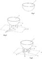
Figure 1 shows an axonometric view of an example of three-dimensional object to be made through stereolithography; -
Figure 2 shows an object obtained by joining the three-dimensional object ofFigure 1 and a part of the supporting structure according to the invention; -
Figure 3 shows an object obtained by joining the three- dimensional object ofFigure 1 and the supporting structure according to the invention; -
Figure 4 shows a diagram of the links between the elements of the supporting structure ofFigure 3 , in plan view; -
Figure 5 shows a diagram of the links related to a variant of the supporting structure ofFigure 3 , in plan view; -
Figure 6 shows a variant of the supporting structure ofFigure 3 ; -
Figure 7 shows a variant of the supporting structure ofFigure 6 . - The method of the invention for defining a supporting structure for a three-dimensional object to be made through stereolithography is described with reference to the three-dimensional object represented in
Figure 1 and indicated therein by 1. - It should be noted since now that the three-dimensional object 1 has been purposely represented with a very simplified geometry compared to the objects that are commonly produced through stereolithography, in order to make the drawings clearer.
- It is evident, however, that the description provided above can be analogously applied to a three-dimensional object with any geometry.
- First of all the method includes the step of defining a
first surface 3 to be supported, belonging to the three-dimensional object 1. - Obviously, a plurality of said first surfaces to be supported can be defined depending on the geometry of the object, the material used for the stereolithography process and other parameters, if necessary.
- Obviously, the method of the invention can be applied to each one of said first surfaces.
- According to the method, for each first surface 3 a
second surface 4, facing the first one, is defined. - The
second surface 4 can be separate from the three-dimensional object 1, as in the case shown in the figures. - As an alternative, the
second surface 4 may belong to the three-dimensional object 1. - The first option is suitable for a
first surface 3 intended to be arranged so that it faces the modelling plate that supports the three-dimensional object 1 during its production, with no need to interpose other parts of the object itself. - In particular, the
second surface 4 can be defined in such a way that during the actual production of the three-dimensional object it coincides with the surface of said modelling plate. - This last case is the one illustrated in
Figures 2 and 3 , in which saidsecond surface 4 is hatched. - According to the variant embodiment shown in
Figure 6 , thesecond surface 4 belongs to a supportingbase 11 intended to be arranged in contact with said modelling plate. This variant is described in greater detail below. - When, instead, the
first surface 3 is arranged in a cavity of the three-dimensional object 1 or, in any case, faces another surface of the object itself, thesecond surface 4 preferably belongs to the object. - In the latter case, the
second surface 4 is preferably the surface of the three-dimensional object 1 that directly faces thefirst surface 3, for example the surface of said cavity that is opposite thefirst surface 3. - Obviously, in a single three-dimensional object 1 there may be a combination of the cases described above.
- Once the
first surface 3 and thesecond surface 4 have been defined, the method includes the step of defining a plurality of supportingelements 5 in an elongated shape, extending from thefirst surface 3 to thesecond surface 4, as shown inFigure 2 . - Analogously to that which has already been remarked, it should be pointed out that the supporting
elements 5 shown inFigure 2 have been purposely represented in a reduced number in order to simplify the representation. - It is however evident that, in general, the number of supporting elements will be higher than that shown in the figures and will depend on the geometry of the object and on other parameters.
- In general, the number of supporting elements will be higher than two and in most cases higher than three.
- Notwithstanding the above, the method described herein can be applied in any case, independently of the number of supporting elements provided. Preferably but not necessarily, said supporting
elements 5 are conical or cylindrical in shape, but they can obviously be also in other shapes. - The supporting
elements 5 can also be provided with branches at one or both ends, in such a way as to be connected to the corresponding surface in several points. This type of branching is not represented in the figures, but is known per se. - Preferably, each supporting
element 5 has a thinner portion located at the level of thefirst surface 3 and/or of thesecond surface 4, not represented in the figures, but known per se. - Said thinner portion offers the advantage of favouring the detachment of the supporting
element 5 from thesurfaces 3 and/or 4 once the stereolithography process during which the three-dimensional object 1 is actually produced has been completed. - The method also includes the operation of defining, for each pair of supporting
elements 5, one or more reinforcingelements 6 in an elongated shape, preferably conical or cylindrical, that connect the two supportingelements 5 of said pair, as shown inFigure 3 . - To advantage, said reinforcing
elements 6 make it possible to increase the resistance of the supportingstructure 2 while maintaining the same overall volume of the latter or, alternatively, to reduce the volume of the supportingstructure 2 while ensuring the same degree of resistance. - According to the invention, the pairs of supporting
elements 5 to be connected to said reinforcingelements 6 are selected with the aid of the well-known graph theory. - In particular, the method includes the operation of defining a
reference point 7 belonging to each supportingelement 5. - A connected acyclic graph is then generated whose vertices are the
reference points 7. - As is known, a graph is a mathematical construction consisting of one pair of sets V and E, wherein the elements of the first set V are points in space, called "vertices", while the elements of the second set E represent a corresponding number of links between pairs of vertices, which are called "edges".
- Therefore, in mathematical notation, a graph G is expressed with the following relation

- From a formal point of view, an edge that connects two generic vertices u and v is represented by the pair (u, v) of the vertices themselves.
- Clearly, given a set of vertices V, there is an infinity of possible graphs comprising said set V, which differ from one another for the set of edges E. The requisite that the graph be a connected acyclic graph limits said graphs to a finite number.
- In particular, the requisite that the graph be connected implies that for any two vertices of the graph there is a succession of edges that connect them.
- The requisite that the graph be acyclic implies that any two vertices are connected through one and only one succession of edges.
- In the theory of graphs, a connected acyclic graph of the type mentioned above is also called a "tree".
- Advantageously, the connected acyclic graphs corresponding to a given set of vertices can be identified through suitable algorithms that are known per se.
-
Figure 4 shows a schematic plan view of a connectedacyclic graph 8 whose vertices are thereference points 7, which obviously is only one of the possible graphs having said properties. - In particular, each
edge 9 of thegraph 8 is represented inFigure 4 by a dashed segment that extends between therespective reference points 7. According to the method of the invention, the pairs of supportingelements 5 to be connected are identified by means of said connectedacyclic graph 8. - In particular, for each
edge 9 of the graph 8 a pair is defined that comprises the two supportingelements 5 corresponding to the ends of theedge 9 itself. - By defining the pairs of supporting
elements 5 in the manner described above, it is possible to achieve the purpose of limiting the volume of the supportingstructure 2 with respect to those obtainable with the known methods. - In fact, as is known from the theory of graphs, connected acyclic graphs are those graphs which, among all the graphs that can be defined on the same vertices, have the lowest number of edges, while at the same time maintaining all the vertices connected to one another.
- In particular, the number of edges of a connected acyclic graph is equal to the number of vertices minus one.
- Therefore, for a given number of reinforcing
elements 6 between each pair of supportingelements 5, the definition of the pairs of supportingelements 5 as described above makes it possible to limit the number of links between said supporting elements and, therefore, the number of reinforcingelements 6, while at the same time maintaining all the supportingelements 5 connected to one another so as to obtain a stable supportingstructure 2. Advantageously, using the theory of graphs to define the pairs of reinforcingelements 5 makes it possible to use said known algorithms to generate a connectedacyclic graph 8. - Preferably, for one or more pairs of supporting elements 5 a plurality of distinct reinforcing
elements 6 is defined, which are indicatively shown inFigure 3 . - Advantageously, the presence of several reinforcing
elements 6 for one pair of supportingelements 5 makes it possible to obtain a more stable connection between the supportingelements 5, especially when these are particularly long. - Consequently, to advantage, also the supporting
structure 2 is more stable. Obviously, in variant embodiments of the invention, the number of reinforcingelements 6 that connect a given pair of supportingelements 5 can be any and, moreover, it can vary in the different pairs of supportingelements 5. Preferably, but not necessarily, the reinforcingelements 6 that connect each pair of supportingelements 5 are arranged according to mutually incident directions, in such a way as to define a sort of lattice, thus further increasing the stability of the connection. - Preferably, said connected
acyclic graph 8 is defined in such a way that it coincides with the minimum spanning tree of a complete graph having the same vertices as the connectedacyclic graph 8 and in which each edge is associated with a weight corresponding to the distance between the ends of the edge itself. - More precisely, it is known that a complete graph is a graph in which any pair of vertices is connected by at least one edge.
- As is also known, the minimum spanning tree of a graph can be defined only after assigning a weight to each edge of the graph itself, as it is defined as that specific subset of the graph for which the sum of said weights is minimal.
- In particular, if the weights are selected in such a way as to represent the lengths of the edges as described above, the minimum spanning tree corresponds to the tree whose edges have the minimum overall length. Therefore, the criterion just described above to define the pairs of supporting
elements 5 allows to obtain a supportingstructure 2 in which the reinforcingelements 6 extend over the shortest possible path. - Consequently, to advantage, it is possible to minimize the volume of the supporting
structure 2 while maintaining the same number of reinforcingelements 6 between each pair of supportingelements 5. - Advantageously, said minimum spanning tree can be defined using mathematical algorithms known in the theory of graphs.
- According to construction variants of the invention, said weights can be defined in a different manner from that which has been described above.
- For example, it may be appropriate to connect one or more pairs of supporting
elements 5 with reinforcing elements developed according to curved trajectories and/or broken lines. In this case, the edges are assigned corresponding weights equal to the lengths of the corresponding trajectories. According to a construction variant of the invention, an additional pair of supportingelements 5 is defined at the level of each vertex having order 1 of the connectedacyclic graph 8. - In particular, said additional pair comprises a first supporting
element 5 corresponding to said vertex having order 1 and a second supportingelement 5 corresponding to a vertex of thegraph 8 not connected to the first vertex. - As is known, a vertex having order 1 is defined as a vertex appearing in only one edge of the graph, meaning a vertex connected to one and only one vertex of the graph.
- Therefore, it can be understood that the definition of the additional pair described above advantageously implies that any supporting
element 5 is connected to at least other two supportingelements 5, with the advantage of increasing the overall structural resistance of the supportingstructure 2. Indicatively, a possible additional pair is represented inFigure 5 and indicated therein by thereference number 10. - Preferably, said additional pair is defined in such a way that the distance between the corresponding vertices of the connected
acyclic graph 8 is the minimum possible distance. - Advantageously, the condition just described above makes it possible to limit to the minimum the length of the reinforcing
elements 6 used to connect said additional pairs of supportingelements 5. - Preferably, the additional pairs are defined between two supporting
elements 5, both corresponding to vertices of order 1, in such a way as to minimize the number of additional pairs introduced. - As already mentioned,
Figure 6 represents a construction variant of the invention in which thesecond surface 4 is separate from the three-dimensional object 1. - In particular, all of the reinforcing
elements 6 lie on saidsecond surface 4 and, therefore, connect the ends of the supportingelements 5. - Said configuration is such that the reinforcing
elements 6 define a supportingbase 11 suited to be arranged in contact with the modelling plate of the stereolithography machine in order to support the three-dimensional object 1. Advantageously, a supportingbase 11 shaped as described above has a much smaller volume than the supporting bases usually provided, which extend also over areas that are not affected by the presence of the supportingelements 5. - Preferably, the
second surface 4 is planar, so that said supportingbase 11 can adapt to a modelling plate provided with a planar surface, which corresponds to the type of modelling plate commonly used. - The supporting
base 11 represented inFigure 6 is defined by reinforcingelements 6 that extend between the supportingelements 5 according to the same links represented inFigure 4 . -
Figure 7 represents a further construction variant of the invention, in which the supportingbase 11 has the same links shown inFigure 5 . - This variant differs from the one shown in
Figure 6 due to the presence of an additional link between the supportingelements 5, corresponding to that indicated with thereference number 10 inFigure 5 . - According to the above, it can be understood that the graphs that can be obtained with the method according to the several variants described above can be used to make both a supporting
structure 2 with a lattice-type configuration of the type shown inFigure 3 and a supportingbase 11 of the type shown inFigures 6 and 7 . - Obviously, in variant embodiments of the invention the supporting
structure 2 can be provided with both types of reinforcingelements 6, not necessarily based on the same pairs of supportingelements 5. - As regards the definition of the
reference points 7, this is preferably carried out through the definition of a preferably planar reference surface intersecting all the supportingelements 5. - Each
reference point 7 is defined in such a way that it belongs to the intersection area between the corresponding supportingelement 5 and the reference surface. - Preferably, the reference surface is defined in such a way that it passes through the supporting
elements 5 at the height of the respective median points. - According to a variant embodiment, the reference surface is defined in such a way that it coincides with the
first surface 3 or with thesecond surface 4. - A further construction variant includes the definition of a reference surface in the manner described above and then the definition of a supporting point belonging to the area of intersection between each supporting
element 5 and the reference surface. - Each one of said supporting points is projected on a predefined, preferably planar projection surface, in such a way as to obtain a
corresponding reference point 7. - The projection surface may coincide with the
first surface 3 or with thesecond surface 4. - The method described above can be applied also to several groups of supporting
elements 5, wherein the reinforcingelements 6 connect the supportingelements 5 within each group, but do not connect the groups with one another. - In this case, the method is applied separately to each group of supporting
elements 5 in order to generate the respective connectedacyclic graphs 8. - This variant can advantageously be applied to the case in which there are groups of supporting
elements 5 relatively close to one another, but at the same time far away from the other supportingelements 5, since this avoids the presence of excessively long reinforcingelements 6, with no need to neglect the internal stability of each group. - The method described so far is preferably implemented by means of a piece of equipment comprising a computer, not represented in the figures but known per se, provided with a processing unit and a memory support that can be accessed by said processing unit.
- Said equipment comprises means for acquiring a first set of data representative of the geometry of the three-dimensional object 1 and loading it in said memory support.
- The equipment furthermore comprises means for defining the
first surface 3 to be supported and means for defining the respectivesecond surface 4. - The equipment furthermore comprises means for defining the supporting
elements 5, means for defining the pairs of supportingelements 5 and means for defining the reinforcingelements 6 between said pairs. - The equipment also comprises means for generating a second set of data representative of the geometry resulting from the union of the supporting
elements 5 and the reinforcingelements 6 with the three-dimensional object 1 and for loading said second set of data in the memory support. - According to the invention, the means for defining the pairs of supporting
elements 5 comprise means for defining areference point 7 belonging to each supportingelement 5, means for defining said connectedacyclic graph 8 and means for defining one pair of supporting elements for eachedge 9 of said connectedacyclic graph 8 as described above. - Said equipment is preferably configured by means of a computer program product comprising a data support provided with program portions configured in such a way that, when executed on said computer, they define the means of the equipment as described above.
- According to the explanations provided above, it can be understood that the method, the equipment and the computer program product described above achieve all of the set objects.
- In particular, the invention makes it possible to obtain a supporting structure having a reduced volume compared to the supporting structures defined according to the known art.
Claims (14)
- Computer-implemented method for defining a supporting structure (2) for a three-dimensional object (1) to be produced through a stereolithography process, comprising the following operations:- defining a first surface (3) to be supported belonging to said three-dimensional object (1);- defining a second surface (4) facing said first surface (3);- defining a plurality of supporting elements (5) having an elongated shape and extending from said first surface (3) to said second surface (4);- defining a plurality of pairs of said supporting elements (5);- for each pair of said plurality of pairs of supporting elements (5), defining at least one reinforcing element (6) having an elongated shape and connecting the two supporting elements (5) of said pair;said operation of defining said plurality of pairs of supporting elements (5) comprising the following operations:- defining a reference point (7) belonging to each one of said supporting elements (5);- defining a connected acyclic graph (8) having as vertices said reference points (7) and comprising corresponding edges (9) between said vertices;- defining one of said pairs of supporting elements for each one of said edges (9), said pair comprising the two supporting elements (5) corresponding to the ends of said edge (9);characterized in that said operation of defining said plurality of pairs of supporting elements (5) comprises the further operation of defining an additional pair of supporting elements for each vertex having order 1 of said connected acyclic graph (8), said additional pair comprising a first supporting element (5) corresponding to said vertex having order 1 and a second one of said supporting elements (5) not connected to said first supporting element (5) through any of said edges (9).
- Method according to claim 1, wherein said connected acyclic graph (8) is defined in such a way that it coincides with the minimum spanning tree of a complete graph having the same vertices as said connected acyclic graph (8) and in which each edge (9) is assigned a weight equal to the value of the distance between the ends of said edge (9).
- Method according to claim 1 or 2, wherein said additional pairs are defined in such a way that the sum of the distances between the corresponding vertices of said connected acyclic graph (8) is minimal.
- Method according to any of the preceding claims, wherein said operation of defining said at least one reinforcing element (6) includes the operation of defining a plurality of said reinforcing elements (6) distinct from one another for at least one pair of said plurality of pairs of supporting elements (5).
- Method according to any of the preceding claims, wherein said second surface belongs to said three-dimensional object (1).
- Method according to any of the claims from 1 to 4, wherein said second surface (4) is separate from said three-dimensional object (1) and all of said reinforcing elements (6) lie on said second surface (4).
- Method according to claim 6, wherein said second surface (4) is planar.
- Method according to any of the preceding claims, wherein each one of said supporting elements (5) has a corresponding thinner portion located at the level of the first surface (3) or of the corresponding second surface (4).
- Method according to any of the preceding claims, wherein said reinforcing elements (6) have a conical or cylindrical shape.
- Method according to any of the preceding claims, wherein said definition of said reference points (7) comprises the following operations:- defining a reference surface intersecting all of said supporting elements (5);- for each supporting element (5), defining a corresponding reference point (7) in the area of intersection between said supporting element (5) and said reference surface.
- Method according to any of the claims from 1 to 9, wherein said definition of said reference points comprises the following operations:- defining a reference surface intersecting all of said supporting elements (5);- defining a support point in the area of intersection between each supporting element (5) and said reference surface;- defining a projection surface;- defining each one of said reference points (7) as the projection of a corresponding one of said support points on said projection surface.
- Method according to claim 10 or 11, wherein said reference surface coincides with said first surface (3) or with said second surface (4).
- Equipment for defining a supporting structure (2) for a three-dimensional object (1) to be produced through a stereolithography process, comprising:- a computer comprising a processing unit and a memory support accessible by said processing unit;- means for acquiring a first set of data representative of the geometry of said three-dimensional object (1) and for loading said first set of data in said memory support;- means for defining a first surface (3) to be supported belonging to said three-dimensional object (1);- means for defining a second surface (4) facing said first surface (3);- means for defining a plurality of supporting elements (5) having an elongated shape and extending from said first surface (3) to said second surface (4);- means for defining a plurality of pairs of said supporting elements (5);- means for defining, for each pair of said plurality of pairs of supporting elements (5), at least one reinforcing element (6) having an elongated shape and connecting the two corresponding supporting elements (5);- means for generating a second set of data representative of the geometry resulting from the union of said supporting elements (5) and said reinforcing elements (6) with said three-dimensional object (1) and for loading said second set of data in said memory support;said means for defining said plurality of pairs of supporting elements (5) comprising:- means for defining a reference point (7) belonging to each one of said supporting elements (5);- means for defining a connected acyclic graph (8) having as vertices said reference points (7) and comprising corresponding edges (9) between said vertices;- means for defining one pair of supporting elements for each one of said edges (9), said pair comprising the two supporting elements (5) corresponding to the ends of said edge (9);characterized in that said means for defining said plurality of pairs of supporting elements (5) are configured so as to define an additional pair of supporting elements for each vertex having order 1 of said connected acyclic graph (8), said additional pair comprising a first supporting element (5) corresponding to said vertex having order 1 and a second one of said supporting elements (5) not connected to said first supporting element (5) through any of said edges (9).
- Computer program product comprising a data support provided with program portions configured in such a way that, when executed on a computer comprising a processing unit and a memory support accessible by said processing unit, said program portions define:- means for acquiring a first set of data representative of the geometry of said three-dimensional object (1) and for loading said first set of data in said memory support;- means for defining a first surface (3) to be supported belonging to said three-dimensional object (1);- means for defining a second surface (4) facing said first surface (3);- means for defining a plurality of supporting elements (5) having an elongated shape and extending from said first surface (3) to said second surface (4);- means for defining a plurality of pairs of said supporting elements (5);- means for defining, for each pair of said plurality of pairs of supporting elements (5), at least one reinforcing element (6) having an elongated shape and connecting the two corresponding supporting elements (5);- means for generating a second set of data representative of the geometry resulting from the union of said supporting elements (5) and said reinforcing elements (6) with said three-dimensional object (1) and for loading said second set of data in said memory support;said means for defining said plurality of pairs of supporting elements (5) comprising:- means for defining a reference point (7) belonging to each one of said supporting elements (5);- means for defining a connected acyclic graph (8) having as vertices said reference points (7) and comprising corresponding edges (9) between said vertices;- means for defining one pair of supporting elements for each one of said edges (9), said pair comprising the two supporting elements (5) corresponding to the ends of said edge (9);characterized in that said means for defining said plurality of pairs of supporting elements (5) are configured so as to define an additional pair of supporting elements for each vertex having order 1 of said connected acyclic graph (8), said additional pair comprising a first supporting element (5) corresponding to said vertex having order 1 and a second one of said supporting elements (5) not connected to said first supporting element (5) through any of said edges (9).
Applications Claiming Priority (2)
| Application Number | Priority Date | Filing Date | Title |
|---|---|---|---|
| ITVI20140074 | 2014-03-25 | ||
| PCT/IB2015/052139 WO2015145346A1 (en) | 2014-03-25 | 2015-03-24 | Method and equipment for defining a supporting structure for a three-dimensional object to be made through stereolithography |
Publications (2)
| Publication Number | Publication Date |
|---|---|
| EP3122541A1 EP3122541A1 (en) | 2017-02-01 |
| EP3122541B1 true EP3122541B1 (en) | 2019-01-30 |
Family
ID=50943492
Family Applications (1)
| Application Number | Title | Priority Date | Filing Date |
|---|---|---|---|
| EP15720427.2A Active EP3122541B1 (en) | 2014-03-25 | 2015-03-24 | Method and equipment for defining a supporting structure for a three-dimensional object to be made through stereolithography |
Country Status (14)
| Country | Link |
|---|---|
| US (1) | US10300661B2 (en) |
| EP (1) | EP3122541B1 (en) |
| JP (1) | JP6277477B2 (en) |
| KR (1) | KR101866672B1 (en) |
| CN (1) | CN106164913A (en) |
| CA (1) | CA2936171A1 (en) |
| ES (1) | ES2722106T3 (en) |
| IL (1) | IL247196A0 (en) |
| MX (1) | MX2016012429A (en) |
| RU (1) | RU2666444C2 (en) |
| SG (1) | SG11201605308PA (en) |
| TR (1) | TR201905261T4 (en) |
| TW (1) | TWI629162B (en) |
| WO (1) | WO2015145346A1 (en) |
Families Citing this family (17)
| Publication number | Priority date | Publication date | Assignee | Title |
|---|---|---|---|---|
| GB2559914B (en) | 2015-10-07 | 2021-07-14 | Holo Inc | Sub-pixel grayscale three-dimensional printing |
| NZ745973A (en) * | 2016-03-16 | 2020-02-28 | Ricoh Co Ltd | Information processing apparatus, program, information processing method, and modeling system |
| US10252468B2 (en) * | 2016-05-13 | 2019-04-09 | Holo, Inc. | Stereolithography printer |
| US10780641B2 (en) | 2016-09-29 | 2020-09-22 | Holo, Inc. | Enhanced three dimensional printing of vertical edges |
| DE102016219458A1 (en) * | 2016-10-07 | 2018-04-12 | Airbus Defence and Space GmbH | RECEIVING CONTAINER AND METHOD FOR ADDITIVELY MANUFACTURING A RECEIPT CONTAINER |
| IT201600124372A1 (en) * | 2016-12-07 | 2018-06-07 | Dws Srl | STEREOLITHOGRAPHIC MACHINE WITH PERFECT OPTICAL GROUP |
| CN107415217B (en) * | 2017-04-28 | 2019-07-23 | 西安理工大学 | A kind of design method of the indeterminate fixed end roof beam structure with self supporting structure |
| KR101956271B1 (en) * | 2017-06-26 | 2019-03-08 | 호서대학교 산학협력단 | Tree type support and optimum design method thereof |
| WO2019017896A1 (en) * | 2017-07-18 | 2019-01-24 | Hewlett-Packard Development Company, L.P. | Additive manufacturing process to disguise physical characteristics of item |
| CN107727189B (en) * | 2017-11-15 | 2020-01-14 | 珠海赛纳打印科技股份有限公司 | Method and device for acquiring structure volume, non-transitory computer readable storage medium and printer |
| WO2020003312A1 (en) * | 2018-06-28 | 2020-01-02 | Stratasys Ltd. | Structure supporting an object during additive manufacturing and method for forming |
| CN109263049B (en) * | 2018-10-31 | 2020-12-11 | 深圳市诺瓦机器人技术有限公司 | Method, device and system for automatically adding connecting rod |
| US11511485B2 (en) * | 2019-04-02 | 2022-11-29 | Align Technology, Inc. | 3D printed objects with selective overcure regions |
| JP7312063B2 (en) * | 2019-09-09 | 2023-07-20 | 株式会社東芝 | Three-dimensional object manufacturing method and three-dimensional modeling apparatus |
| JP2022057621A (en) * | 2020-09-30 | 2022-04-11 | ブラザー工業株式会社 | Data generation program and three-dimensional modelling system |
| CN112743101B (en) * | 2020-12-29 | 2023-01-24 | 南京晨光集团有限责任公司 | Crack control method for SLM (Selective laser melting) forming of strip-shaped or sheet-shaped structural member |
| CN112873835A (en) * | 2021-01-29 | 2021-06-01 | 优你造科技(北京)有限公司 | 3D printing support body reinforcing method and device |
Family Cites Families (18)
| Publication number | Priority date | Publication date | Assignee | Title |
|---|---|---|---|---|
| KR100257135B1 (en) * | 1988-04-18 | 2000-06-01 | 윌리엄 헐 찰스 | Thermal stereolithography |
| US5999184A (en) * | 1990-10-30 | 1999-12-07 | 3D Systems, Inc. | Simultaneous multiple layer curing in stereolithography |
| BE1008128A3 (en) * | 1994-03-10 | 1996-01-23 | Materialise Nv | Method for supporting an object manufactured by stereo lithography or any rapid prototype manufacturing and method for manufacturing the taking used steunkonstruktie. |
| US6558606B1 (en) * | 2000-01-28 | 2003-05-06 | 3D Systems, Inc. | Stereolithographic process of making a three-dimensional object |
| ATE408850T1 (en) * | 2001-04-10 | 2008-10-15 | Harvard College | MICRO LENS FOR PROJECTION LITHOGRAPHY AND ITS PRODUCTION PROCESS |
| US6907307B2 (en) * | 2002-07-02 | 2005-06-14 | 3D Systems, Inc. | Support volume calculation for a CAD model |
| US6984583B2 (en) * | 2003-09-16 | 2006-01-10 | Micron Technology, Inc. | Stereolithographic method for forming insulative coatings for via holes in semiconductor devices |
| US8046097B2 (en) * | 2007-09-17 | 2011-10-25 | 3D Systems, Inc. | Region-based supports for parts produced by solid freeform fabrication |
| GB0719747D0 (en) * | 2007-10-10 | 2007-11-21 | Materialise Nv | Method and apparatus for automatic support generation for an object made by means of a rapid prototype production method |
| JP5127515B2 (en) * | 2008-03-12 | 2013-01-23 | キヤノン株式会社 | Optical element holding device |
| US8237716B2 (en) * | 2008-09-08 | 2012-08-07 | Fair Isaac Corporation | Algorithm for drawing directed acyclic graphs |
| EP2559533B1 (en) * | 2008-09-26 | 2020-04-15 | United Technologies Corporation | Casting |
| DE102008051478A1 (en) * | 2008-10-13 | 2010-06-02 | Eos Gmbh Electro Optical Systems | Frame for a device for producing a three-dimensional object and device for producing a three-dimensional object with such a frame |
| US8666142B2 (en) * | 2008-11-18 | 2014-03-04 | Global Filtration Systems | System and method for manufacturing |
| DE102010043166A1 (en) * | 2010-10-29 | 2012-05-03 | Eos Gmbh Electro Optical Systems | Device for treating powder for a device for producing a three-dimensional object and device for producing a three-dimensional object |
| EP2690966B8 (en) * | 2011-03-30 | 2023-11-08 | Barry Callebaut AG | Additive manufacturing system and method for printing customized chocolate confections |
| US8821781B2 (en) * | 2011-06-23 | 2014-09-02 | Disney Enterprises, Inc. | Fabricating objects with integral and contoured rear projection |
| CN103578096A (en) * | 2012-07-25 | 2014-02-12 | 上海澜晶数码科技有限公司 | Image segmentation algorithm |
-
2015
- 2015-03-20 TW TW104108903A patent/TWI629162B/en not_active IP Right Cessation
- 2015-03-24 US US15/128,638 patent/US10300661B2/en active Active
- 2015-03-24 JP JP2016543158A patent/JP6277477B2/en active Active
- 2015-03-24 EP EP15720427.2A patent/EP3122541B1/en active Active
- 2015-03-24 SG SG11201605308PA patent/SG11201605308PA/en unknown
- 2015-03-24 ES ES15720427T patent/ES2722106T3/en active Active
- 2015-03-24 CN CN201580016094.4A patent/CN106164913A/en active Pending
- 2015-03-24 MX MX2016012429A patent/MX2016012429A/en unknown
- 2015-03-24 CA CA2936171A patent/CA2936171A1/en not_active Abandoned
- 2015-03-24 RU RU2016140883A patent/RU2666444C2/en not_active IP Right Cessation
- 2015-03-24 WO PCT/IB2015/052139 patent/WO2015145346A1/en active Application Filing
- 2015-03-24 KR KR1020167018977A patent/KR101866672B1/en active IP Right Grant
- 2015-03-24 TR TR2019/05261T patent/TR201905261T4/en unknown
-
2016
- 2016-08-09 IL IL247196A patent/IL247196A0/en unknown
Non-Patent Citations (1)
| Title |
|---|
| None * |
Also Published As
| Publication number | Publication date |
|---|---|
| KR101866672B1 (en) | 2018-06-11 |
| TR201905261T4 (en) | 2019-05-21 |
| TWI629162B (en) | 2018-07-11 |
| RU2016140883A (en) | 2018-04-25 |
| RU2666444C2 (en) | 2018-09-07 |
| WO2015145346A1 (en) | 2015-10-01 |
| EP3122541A1 (en) | 2017-02-01 |
| CA2936171A1 (en) | 2015-10-01 |
| CN106164913A (en) | 2016-11-23 |
| JP6277477B2 (en) | 2018-02-14 |
| KR20160098427A (en) | 2016-08-18 |
| TW201540484A (en) | 2015-11-01 |
| RU2016140883A3 (en) | 2018-04-25 |
| US20180215098A1 (en) | 2018-08-02 |
| SG11201605308PA (en) | 2016-07-28 |
| MX2016012429A (en) | 2016-12-16 |
| ES2722106T3 (en) | 2019-08-07 |
| US10300661B2 (en) | 2019-05-28 |
| JP2017518199A (en) | 2017-07-06 |
| IL247196A0 (en) | 2016-09-29 |
Similar Documents
| Publication | Publication Date | Title |
|---|---|---|
| EP3122541B1 (en) | Method and equipment for defining a supporting structure for a three-dimensional object to be made through stereolithography | |
| JP2017518199A5 (en) | ||
| US8903533B2 (en) | Method and apparatus for automatic support generation for an object made by means of a rapid prototype production method | |
| EP3174692B1 (en) | Improved method for controlling the activity of at least two light radiation sources belonging to a stereolithography machine. | |
| CN105745868B (en) | The method and apparatus of abnormality detection in network | |
| US20150123319A1 (en) | Stereolithography method for producing a three-dimensional object, comprising a movement according to which a supporting surface for said object intermittently approaches the bottom of a container, and stereolithography machine using said method | |
| JP2016198958A (en) | Information processing method, information processing apparatus, three-dimensional object manufacturing method, and three-dimensional modeling apparatus and program | |
| US20160263836A1 (en) | Three-dimensional object forming system | |
| JP6762744B2 (en) | Structure strength prediction method, structure modeling method, structure laminated modeling support method and program | |
| JP2017519264A (en) | Method and apparatus for generating a numerical representation of a three-dimensional object suitable for use in the production of a three-dimensional object by stereolithography | |
| JP6414714B2 (en) | An improved computer-implemented method for defining the development point of a support element of an object made by a stereolithography process | |
| US10589509B2 (en) | Representing an object in terms of sub-volumes | |
| JP4907372B2 (en) | Method for simulating the occurrence of air accumulation in an object to be immersed and a computer-executable program for executing the simulation method | |
| KR20160044221A (en) | System and method of calculating modification cost for welding strain | |
| US11925520B2 (en) | Method of producing a dental object | |
| KR102439049B1 (en) | Design aiding device and method for optimizing pipe support type | |
| JP6157745B2 (en) | Execution time estimation program and execution time estimation device | |
| JP6113677B2 (en) | Conveyance schedule generation device, processing system, conveyance schedule generation method and program | |
| KR20170037129A (en) | three dimensions cuttern sheet and manufactiring method thereof |
Legal Events
| Date | Code | Title | Description |
|---|---|---|---|
| STAA | Information on the status of an ep patent application or granted ep patent |
Free format text: STATUS: THE INTERNATIONAL PUBLICATION HAS BEEN MADE |
|
| PUAI | Public reference made under article 153(3) epc to a published international application that has entered the european phase |
Free format text: ORIGINAL CODE: 0009012 |
|
| STAA | Information on the status of an ep patent application or granted ep patent |
Free format text: STATUS: REQUEST FOR EXAMINATION WAS MADE |
|
| 17P | Request for examination filed |
Effective date: 20161025 |
|
| AK | Designated contracting states |
Kind code of ref document: A1 Designated state(s): AL AT BE BG CH CY CZ DE DK EE ES FI FR GB GR HR HU IE IS IT LI LT LU LV MC MK MT NL NO PL PT RO RS SE SI SK SM TR |
|
| AX | Request for extension of the european patent |
Extension state: BA ME |
|
| DAV | Request for validation of the european patent (deleted) | ||
| DAX | Request for extension of the european patent (deleted) | ||
| REG | Reference to a national code |
Ref country code: DE Ref legal event code: R079 Ref document number: 602015023998 Country of ref document: DE Free format text: PREVIOUS MAIN CLASS: B29C0067000000 Ipc: G06F0017500000 |
|
| RIC1 | Information provided on ipc code assigned before grant |
Ipc: B33Y 40/00 20150101ALI20180711BHEP Ipc: B29C 64/40 20170101ALI20180711BHEP Ipc: B29C 64/386 20170101ALI20180711BHEP Ipc: G06F 17/50 20060101AFI20180711BHEP Ipc: B33Y 10/00 20150101ALI20180711BHEP |
|
| GRAP | Despatch of communication of intention to grant a patent |
Free format text: ORIGINAL CODE: EPIDOSNIGR1 |
|
| STAA | Information on the status of an ep patent application or granted ep patent |
Free format text: STATUS: GRANT OF PATENT IS INTENDED |
|
| INTG | Intention to grant announced |
Effective date: 20180822 |
|
| GRAS | Grant fee paid |
Free format text: ORIGINAL CODE: EPIDOSNIGR3 |
|
| GRAA | (expected) grant |
Free format text: ORIGINAL CODE: 0009210 |
|
| STAA | Information on the status of an ep patent application or granted ep patent |
Free format text: STATUS: THE PATENT HAS BEEN GRANTED |
|
| AK | Designated contracting states |
Kind code of ref document: B1 Designated state(s): AL AT BE BG CH CY CZ DE DK EE ES FI FR GB GR HR HU IE IS IT LI LT LU LV MC MK MT NL NO PL PT RO RS SE SI SK SM TR |
|
| REG | Reference to a national code |
Ref country code: GB Ref legal event code: FG4D |
|
| REG | Reference to a national code |
Ref country code: CH Ref legal event code: EP |
|
| REG | Reference to a national code |
Ref country code: AT Ref legal event code: REF Ref document number: 1093831 Country of ref document: AT Kind code of ref document: T Effective date: 20190215 |
|
| REG | Reference to a national code |
Ref country code: IE Ref legal event code: FG4D |
|
| REG | Reference to a national code |
Ref country code: DE Ref legal event code: R096 Ref document number: 602015023998 Country of ref document: DE |
|
| REG | Reference to a national code |
Ref country code: CH Ref legal event code: NV Representative=s name: DENNEMEYER AG, CH |
|
| PGFP | Annual fee paid to national office [announced via postgrant information from national office to epo] |
Ref country code: CH Payment date: 20190320 Year of fee payment: 5 Ref country code: GB Payment date: 20190320 Year of fee payment: 5 Ref country code: FR Payment date: 20190322 Year of fee payment: 5 |
|
| REG | Reference to a national code |
Ref country code: NL Ref legal event code: FP |
|
| PGFP | Annual fee paid to national office [announced via postgrant information from national office to epo] |
Ref country code: BE Payment date: 20190320 Year of fee payment: 5 Ref country code: NL Payment date: 20190320 Year of fee payment: 5 |
|
| REG | Reference to a national code |
Ref country code: LT Ref legal event code: MG4D |
|
| PG25 | Lapsed in a contracting state [announced via postgrant information from national office to epo] |
Ref country code: PL Free format text: LAPSE BECAUSE OF FAILURE TO SUBMIT A TRANSLATION OF THE DESCRIPTION OR TO PAY THE FEE WITHIN THE PRESCRIBED TIME-LIMIT Effective date: 20190130 Ref country code: LT Free format text: LAPSE BECAUSE OF FAILURE TO SUBMIT A TRANSLATION OF THE DESCRIPTION OR TO PAY THE FEE WITHIN THE PRESCRIBED TIME-LIMIT Effective date: 20190130 Ref country code: NO Free format text: LAPSE BECAUSE OF FAILURE TO SUBMIT A TRANSLATION OF THE DESCRIPTION OR TO PAY THE FEE WITHIN THE PRESCRIBED TIME-LIMIT Effective date: 20190430 Ref country code: SE Free format text: LAPSE BECAUSE OF FAILURE TO SUBMIT A TRANSLATION OF THE DESCRIPTION OR TO PAY THE FEE WITHIN THE PRESCRIBED TIME-LIMIT Effective date: 20190130 Ref country code: FI Free format text: LAPSE BECAUSE OF FAILURE TO SUBMIT A TRANSLATION OF THE DESCRIPTION OR TO PAY THE FEE WITHIN THE PRESCRIBED TIME-LIMIT Effective date: 20190130 Ref country code: PT Free format text: LAPSE BECAUSE OF FAILURE TO SUBMIT A TRANSLATION OF THE DESCRIPTION OR TO PAY THE FEE WITHIN THE PRESCRIBED TIME-LIMIT Effective date: 20190530 |
|
| PGFP | Annual fee paid to national office [announced via postgrant information from national office to epo] |
Ref country code: ES Payment date: 20190619 Year of fee payment: 5 |
|
| REG | Reference to a national code |
Ref country code: ES Ref legal event code: FG2A Ref document number: 2722106 Country of ref document: ES Kind code of ref document: T3 Effective date: 20190807 |
|
| PG25 | Lapsed in a contracting state [announced via postgrant information from national office to epo] |
Ref country code: IS Free format text: LAPSE BECAUSE OF FAILURE TO SUBMIT A TRANSLATION OF THE DESCRIPTION OR TO PAY THE FEE WITHIN THE PRESCRIBED TIME-LIMIT Effective date: 20190530 Ref country code: LV Free format text: LAPSE BECAUSE OF FAILURE TO SUBMIT A TRANSLATION OF THE DESCRIPTION OR TO PAY THE FEE WITHIN THE PRESCRIBED TIME-LIMIT Effective date: 20190130 Ref country code: HR Free format text: LAPSE BECAUSE OF FAILURE TO SUBMIT A TRANSLATION OF THE DESCRIPTION OR TO PAY THE FEE WITHIN THE PRESCRIBED TIME-LIMIT Effective date: 20190130 Ref country code: GR Free format text: LAPSE BECAUSE OF FAILURE TO SUBMIT A TRANSLATION OF THE DESCRIPTION OR TO PAY THE FEE WITHIN THE PRESCRIBED TIME-LIMIT Effective date: 20190501 Ref country code: BG Free format text: LAPSE BECAUSE OF FAILURE TO SUBMIT A TRANSLATION OF THE DESCRIPTION OR TO PAY THE FEE WITHIN THE PRESCRIBED TIME-LIMIT Effective date: 20190430 Ref country code: RS Free format text: LAPSE BECAUSE OF FAILURE TO SUBMIT A TRANSLATION OF THE DESCRIPTION OR TO PAY THE FEE WITHIN THE PRESCRIBED TIME-LIMIT Effective date: 20190130 |
|
| PGFP | Annual fee paid to national office [announced via postgrant information from national office to epo] |
Ref country code: TR Payment date: 20190410 Year of fee payment: 5 |
|
| PG25 | Lapsed in a contracting state [announced via postgrant information from national office to epo] |
Ref country code: AL Free format text: LAPSE BECAUSE OF FAILURE TO SUBMIT A TRANSLATION OF THE DESCRIPTION OR TO PAY THE FEE WITHIN THE PRESCRIBED TIME-LIMIT Effective date: 20190130 Ref country code: MC Free format text: LAPSE BECAUSE OF FAILURE TO SUBMIT A TRANSLATION OF THE DESCRIPTION OR TO PAY THE FEE WITHIN THE PRESCRIBED TIME-LIMIT Effective date: 20190130 Ref country code: CZ Free format text: LAPSE BECAUSE OF FAILURE TO SUBMIT A TRANSLATION OF THE DESCRIPTION OR TO PAY THE FEE WITHIN THE PRESCRIBED TIME-LIMIT Effective date: 20190130 Ref country code: RO Free format text: LAPSE BECAUSE OF FAILURE TO SUBMIT A TRANSLATION OF THE DESCRIPTION OR TO PAY THE FEE WITHIN THE PRESCRIBED TIME-LIMIT Effective date: 20190130 Ref country code: EE Free format text: LAPSE BECAUSE OF FAILURE TO SUBMIT A TRANSLATION OF THE DESCRIPTION OR TO PAY THE FEE WITHIN THE PRESCRIBED TIME-LIMIT Effective date: 20190130 Ref country code: DK Free format text: LAPSE BECAUSE OF FAILURE TO SUBMIT A TRANSLATION OF THE DESCRIPTION OR TO PAY THE FEE WITHIN THE PRESCRIBED TIME-LIMIT Effective date: 20190130 Ref country code: SK Free format text: LAPSE BECAUSE OF FAILURE TO SUBMIT A TRANSLATION OF THE DESCRIPTION OR TO PAY THE FEE WITHIN THE PRESCRIBED TIME-LIMIT Effective date: 20190130 |
|
| REG | Reference to a national code |
Ref country code: DE Ref legal event code: R097 Ref document number: 602015023998 Country of ref document: DE |
|
| PG25 | Lapsed in a contracting state [announced via postgrant information from national office to epo] |
Ref country code: LU Free format text: LAPSE BECAUSE OF NON-PAYMENT OF DUE FEES Effective date: 20190324 Ref country code: SM Free format text: LAPSE BECAUSE OF FAILURE TO SUBMIT A TRANSLATION OF THE DESCRIPTION OR TO PAY THE FEE WITHIN THE PRESCRIBED TIME-LIMIT Effective date: 20190130 |
|
| PLBE | No opposition filed within time limit |
Free format text: ORIGINAL CODE: 0009261 |
|
| STAA | Information on the status of an ep patent application or granted ep patent |
Free format text: STATUS: NO OPPOSITION FILED WITHIN TIME LIMIT |
|
| 26N | No opposition filed |
Effective date: 20191031 |
|
| PG25 | Lapsed in a contracting state [announced via postgrant information from national office to epo] |
Ref country code: IE Free format text: LAPSE BECAUSE OF NON-PAYMENT OF DUE FEES Effective date: 20190324 |
|
| PG25 | Lapsed in a contracting state [announced via postgrant information from national office to epo] |
Ref country code: SI Free format text: LAPSE BECAUSE OF FAILURE TO SUBMIT A TRANSLATION OF THE DESCRIPTION OR TO PAY THE FEE WITHIN THE PRESCRIBED TIME-LIMIT Effective date: 20190130 |
|
| REG | Reference to a national code |
Ref country code: DE Ref legal event code: R079 Ref document number: 602015023998 Country of ref document: DE Free format text: PREVIOUS MAIN CLASS: G06F0017500000 Ipc: G06F0030000000 |
|
| PG25 | Lapsed in a contracting state [announced via postgrant information from national office to epo] |
Ref country code: MT Free format text: LAPSE BECAUSE OF NON-PAYMENT OF DUE FEES Effective date: 20190324 |
|
| REG | Reference to a national code |
Ref country code: CH Ref legal event code: PL |
|
| REG | Reference to a national code |
Ref country code: NL Ref legal event code: MM Effective date: 20200401 |
|
| REG | Reference to a national code |
Ref country code: BE Ref legal event code: MM Effective date: 20200331 |
|
| PG25 | Lapsed in a contracting state [announced via postgrant information from national office to epo] |
Ref country code: NL Free format text: LAPSE BECAUSE OF NON-PAYMENT OF DUE FEES Effective date: 20200401 |
|
| PG25 | Lapsed in a contracting state [announced via postgrant information from national office to epo] |
Ref country code: FR Free format text: LAPSE BECAUSE OF NON-PAYMENT OF DUE FEES Effective date: 20200331 Ref country code: LI Free format text: LAPSE BECAUSE OF NON-PAYMENT OF DUE FEES Effective date: 20200331 Ref country code: CH Free format text: LAPSE BECAUSE OF NON-PAYMENT OF DUE FEES Effective date: 20200331 |
|
| PG25 | Lapsed in a contracting state [announced via postgrant information from national office to epo] |
Ref country code: BE Free format text: LAPSE BECAUSE OF NON-PAYMENT OF DUE FEES Effective date: 20200331 |
|
| GBPC | Gb: european patent ceased through non-payment of renewal fee |
Effective date: 20200324 |
|
| PG25 | Lapsed in a contracting state [announced via postgrant information from national office to epo] |
Ref country code: GB Free format text: LAPSE BECAUSE OF NON-PAYMENT OF DUE FEES Effective date: 20200324 |
|
| REG | Reference to a national code |
Ref country code: AT Ref legal event code: MM01 Ref document number: 1093831 Country of ref document: AT Kind code of ref document: T Effective date: 20200324 |
|
| PG25 | Lapsed in a contracting state [announced via postgrant information from national office to epo] |
Ref country code: CY Free format text: LAPSE BECAUSE OF FAILURE TO SUBMIT A TRANSLATION OF THE DESCRIPTION OR TO PAY THE FEE WITHIN THE PRESCRIBED TIME-LIMIT Effective date: 20190130 |
|
| PG25 | Lapsed in a contracting state [announced via postgrant information from national office to epo] |
Ref country code: HU Free format text: LAPSE BECAUSE OF FAILURE TO SUBMIT A TRANSLATION OF THE DESCRIPTION OR TO PAY THE FEE WITHIN THE PRESCRIBED TIME-LIMIT; INVALID AB INITIO Effective date: 20150324 |
|
| REG | Reference to a national code |
Ref country code: ES Ref legal event code: FD2A Effective date: 20210802 |
|
| PG25 | Lapsed in a contracting state [announced via postgrant information from national office to epo] |
Ref country code: AT Free format text: LAPSE BECAUSE OF NON-PAYMENT OF DUE FEES Effective date: 20200324 |
|
| PG25 | Lapsed in a contracting state [announced via postgrant information from national office to epo] |
Ref country code: ES Free format text: LAPSE BECAUSE OF NON-PAYMENT OF DUE FEES Effective date: 20200325 |
|
| PG25 | Lapsed in a contracting state [announced via postgrant information from national office to epo] |
Ref country code: TR Free format text: LAPSE BECAUSE OF NON-PAYMENT OF DUE FEES Effective date: 20200324 Ref country code: MK Free format text: LAPSE BECAUSE OF FAILURE TO SUBMIT A TRANSLATION OF THE DESCRIPTION OR TO PAY THE FEE WITHIN THE PRESCRIBED TIME-LIMIT Effective date: 20190130 |
|
| REG | Reference to a national code |
Ref country code: AT Ref legal event code: UEP Ref document number: 1093831 Country of ref document: AT Kind code of ref document: T Effective date: 20190130 |
|
| PGFP | Annual fee paid to national office [announced via postgrant information from national office to epo] |
Ref country code: IT Payment date: 20230302 Year of fee payment: 9 |
|
| P01 | Opt-out of the competence of the unified patent court (upc) registered |
Effective date: 20230707 |
|
| PGFP | Annual fee paid to national office [announced via postgrant information from national office to epo] |
Ref country code: DE Payment date: 20240328 Year of fee payment: 10 |