EP3119351B1 - Mitral valve replacement toggle cell securement - Google Patents
Mitral valve replacement toggle cell securement Download PDFInfo
- Publication number
- EP3119351B1 EP3119351B1 EP15714325.6A EP15714325A EP3119351B1 EP 3119351 B1 EP3119351 B1 EP 3119351B1 EP 15714325 A EP15714325 A EP 15714325A EP 3119351 B1 EP3119351 B1 EP 3119351B1
- Authority
- EP
- European Patent Office
- Prior art keywords
- struts
- cell
- strut
- prosthetic heart
- heart valve
- Prior art date
- Legal status (The legal status is an assumption and is not a legal conclusion. Google has not performed a legal analysis and makes no representation as to the accuracy of the status listed.)
- Active
Links
- 210000004115 mitral valve Anatomy 0.000 title description 35
- 210000003709 heart valve Anatomy 0.000 claims description 109
- 210000005240 left ventricle Anatomy 0.000 description 12
- 210000005246 left atrium Anatomy 0.000 description 11
- 230000004323 axial length Effects 0.000 description 7
- 230000006870 function Effects 0.000 description 7
- 238000000034 method Methods 0.000 description 6
- 238000002513 implantation Methods 0.000 description 5
- 238000013459 approach Methods 0.000 description 4
- 230000001746 atrial effect Effects 0.000 description 4
- 229910003460 diamond Inorganic materials 0.000 description 4
- 239000010432 diamond Substances 0.000 description 4
- 230000007246 mechanism Effects 0.000 description 4
- 210000001519 tissue Anatomy 0.000 description 4
- 239000008280 blood Substances 0.000 description 3
- 210000004369 blood Anatomy 0.000 description 3
- 230000017531 blood circulation Effects 0.000 description 3
- 229910001285 shape-memory alloy Inorganic materials 0.000 description 3
- 230000009471 action Effects 0.000 description 2
- 238000004873 anchoring Methods 0.000 description 2
- 230000008901 benefit Effects 0.000 description 2
- 210000003698 chordae tendineae Anatomy 0.000 description 2
- 210000005003 heart tissue Anatomy 0.000 description 2
- 239000007943 implant Substances 0.000 description 2
- 239000000463 material Substances 0.000 description 2
- 229910001000 nickel titanium Inorganic materials 0.000 description 2
- HLXZNVUGXRDIFK-UHFFFAOYSA-N nickel titanium Chemical compound [Ti].[Ti].[Ti].[Ti].[Ti].[Ti].[Ti].[Ti].[Ti].[Ti].[Ti].[Ni].[Ni].[Ni].[Ni].[Ni].[Ni].[Ni].[Ni].[Ni].[Ni].[Ni].[Ni].[Ni].[Ni] HLXZNVUGXRDIFK-UHFFFAOYSA-N 0.000 description 2
- 229920001343 polytetrafluoroethylene Polymers 0.000 description 2
- 239000004810 polytetrafluoroethylene Substances 0.000 description 2
- 210000005245 right atrium Anatomy 0.000 description 2
- 230000007704 transition Effects 0.000 description 2
- 241000283690 Bos taurus Species 0.000 description 1
- 206010020772 Hypertension Diseases 0.000 description 1
- MWCLLHOVUTZFKS-UHFFFAOYSA-N Methyl cyanoacrylate Chemical compound COC(=O)C(=C)C#N MWCLLHOVUTZFKS-UHFFFAOYSA-N 0.000 description 1
- 210000000709 aorta Anatomy 0.000 description 1
- 210000002376 aorta thoracic Anatomy 0.000 description 1
- 210000001765 aortic valve Anatomy 0.000 description 1
- 239000000560 biocompatible material Substances 0.000 description 1
- 239000012620 biological material Substances 0.000 description 1
- 230000036772 blood pressure Effects 0.000 description 1
- 230000000747 cardiac effect Effects 0.000 description 1
- 230000006835 compression Effects 0.000 description 1
- 238000007906 compression Methods 0.000 description 1
- 230000001419 dependent effect Effects 0.000 description 1
- 238000002297 emergency surgery Methods 0.000 description 1
- 239000004744 fabric Substances 0.000 description 1
- 210000002837 heart atrium Anatomy 0.000 description 1
- 238000009998 heat setting Methods 0.000 description 1
- 238000001727 in vivo Methods 0.000 description 1
- 230000002452 interceptive effect Effects 0.000 description 1
- 238000012986 modification Methods 0.000 description 1
- 230000004048 modification Effects 0.000 description 1
- 210000003540 papillary muscle Anatomy 0.000 description 1
- 210000003516 pericardium Anatomy 0.000 description 1
- 229920000642 polymer Polymers 0.000 description 1
- -1 polytetrafluoroethylene Polymers 0.000 description 1
- 210000005241 right ventricle Anatomy 0.000 description 1
- 230000000087 stabilizing effect Effects 0.000 description 1
- 238000001356 surgical procedure Methods 0.000 description 1
- 210000002435 tendon Anatomy 0.000 description 1
- 210000000591 tricuspid valve Anatomy 0.000 description 1
- 150000003673 urethanes Chemical class 0.000 description 1
- 230000002861 ventricular Effects 0.000 description 1
Images


Classifications
-
- A—HUMAN NECESSITIES
- A61—MEDICAL OR VETERINARY SCIENCE; HYGIENE
- A61F—FILTERS IMPLANTABLE INTO BLOOD VESSELS; PROSTHESES; DEVICES PROVIDING PATENCY TO, OR PREVENTING COLLAPSING OF, TUBULAR STRUCTURES OF THE BODY, e.g. STENTS; ORTHOPAEDIC, NURSING OR CONTRACEPTIVE DEVICES; FOMENTATION; TREATMENT OR PROTECTION OF EYES OR EARS; BANDAGES, DRESSINGS OR ABSORBENT PADS; FIRST-AID KITS
- A61F2/00—Filters implantable into blood vessels; Prostheses, i.e. artificial substitutes or replacements for parts of the body; Appliances for connecting them with the body; Devices providing patency to, or preventing collapsing of, tubular structures of the body, e.g. stents
- A61F2/02—Prostheses implantable into the body
- A61F2/24—Heart valves ; Vascular valves, e.g. venous valves; Heart implants, e.g. passive devices for improving the function of the native valve or the heart muscle; Transmyocardial revascularisation [TMR] devices; Valves implantable in the body
- A61F2/2412—Heart valves ; Vascular valves, e.g. venous valves; Heart implants, e.g. passive devices for improving the function of the native valve or the heart muscle; Transmyocardial revascularisation [TMR] devices; Valves implantable in the body with soft flexible valve members, e.g. tissue valves shaped like natural valves
- A61F2/2418—Scaffolds therefor, e.g. support stents
-
- A—HUMAN NECESSITIES
- A61—MEDICAL OR VETERINARY SCIENCE; HYGIENE
- A61F—FILTERS IMPLANTABLE INTO BLOOD VESSELS; PROSTHESES; DEVICES PROVIDING PATENCY TO, OR PREVENTING COLLAPSING OF, TUBULAR STRUCTURES OF THE BODY, e.g. STENTS; ORTHOPAEDIC, NURSING OR CONTRACEPTIVE DEVICES; FOMENTATION; TREATMENT OR PROTECTION OF EYES OR EARS; BANDAGES, DRESSINGS OR ABSORBENT PADS; FIRST-AID KITS
- A61F2/00—Filters implantable into blood vessels; Prostheses, i.e. artificial substitutes or replacements for parts of the body; Appliances for connecting them with the body; Devices providing patency to, or preventing collapsing of, tubular structures of the body, e.g. stents
- A61F2/02—Prostheses implantable into the body
- A61F2/24—Heart valves ; Vascular valves, e.g. venous valves; Heart implants, e.g. passive devices for improving the function of the native valve or the heart muscle; Transmyocardial revascularisation [TMR] devices; Valves implantable in the body
- A61F2/2427—Devices for manipulating or deploying heart valves during implantation
-
- A—HUMAN NECESSITIES
- A61—MEDICAL OR VETERINARY SCIENCE; HYGIENE
- A61F—FILTERS IMPLANTABLE INTO BLOOD VESSELS; PROSTHESES; DEVICES PROVIDING PATENCY TO, OR PREVENTING COLLAPSING OF, TUBULAR STRUCTURES OF THE BODY, e.g. STENTS; ORTHOPAEDIC, NURSING OR CONTRACEPTIVE DEVICES; FOMENTATION; TREATMENT OR PROTECTION OF EYES OR EARS; BANDAGES, DRESSINGS OR ABSORBENT PADS; FIRST-AID KITS
- A61F2220/00—Fixations or connections for prostheses classified in groups A61F2/00 - A61F2/26 or A61F2/82 or A61F9/00 or A61F11/00 or subgroups thereof
- A61F2220/0008—Fixation appliances for connecting prostheses to the body
Definitions
- the present disclosure relates to heart valve replacement and, in particular, to collapsible prosthetic heart valves. More particularly, the present disclosure relates to devices and methods for securing collapsible prosthetic heart, valves within native valve annuluses.
- Prosthetic heart valves that are collapsible to a relatively small, circumferential size can be delivered into a patient less invasively than valves that are not collapsible.
- a collapsible valve may be delivered into a patient via a tube-like delivery apparatus such as a catheter, a trocar, a laparoscopic instrument, or the like. This collapsibility can avoid the need for a more invasive procedure such as full open-chest, open-heart surgery.
- Collapsible prosthetic heart valves typically take the form of a valve structure mounted on a stent.
- a stent There are two types of stents on which the valve structures are ordinarily mounted: a self-expanding stent and a balloon-expandable stent.
- the valve is generally first collapsed or crimped to reduce its circumferential size.
- the prosthetic valve When a collapsed prosthetic valve has reached the desired implant site in the patient (e.g., at or near the annulus of the patient's heart valve that is to be replaced by the prosthetic valve) , the prosthetic valve can be deployed or released from the delivery apparatus and. re-expanded to full operating size. For balloon-expandable valves, this generally involves releasing the entire valve, assuring its proper location, and then expanding a balloon positioned, within the valve stent. For self-expand i.ng valves, on the other hand, the stent automatically expands as the sheath covering the valve is withdrawn.
- WO 2011/002996 and WO 2008/002441 both disclose collapsible and expandable stents.
- a prosthetic heart valve comprising: a collapsible and expandable stent extending in an axial direction from an outflow end to an inflow end, comprising: a plurality of first cells, each first cell having an open space defined by a first plurality of struts; a second cell nested in the open space of one of the first cells, the second cell being defined by a second plurality of struts; and first and second connecting struts connecting the second cell to the one of the first cells; wherein the second cell is configured to pivot about the first and second connecting struts with respect to the one of the first cells, and a collapsible and expandable valve assembly disposed within the stent and having a plurality of leaflets; characterized by the one of the first cells defining a surface and the second cell including first and second struts that do not lie within the surface when no external force is applied to the stent.
- the stent In conventional collapsible heart valves, the stent is usually anchored within the native valve annulus via the radial force exerted by the expanding stent against the native valve annulus. If the radial force is too high, damage may occur to heart tissue. If, instead, the radial force is too low, the heart valve may move from its implanted position. For prosthetic mitral valves, for example, the implanted valve may move into either the left ventricle or the left atrium, requiring emergency surgery to remove the displaced valve. Moreover, in certain applications, such as mitral valve replacement, the heart valve may require a lower profile so as not to interfere with surrounding tissue structures. Such a low profile may make it difficult for the valve to remain in place. Other designs may include hooks or similar features that passively engage tissue until tissue ingrowth is established.
- the term “inflow end,” when used in connection with a prosthetic mitral heart valve, refers to the end of the heart valve closest to the left atrium when the heart valve is implanted in a patient
- the term “outflow end,” when used in connection with a prosthetic mitral heart valve refers to the end of the heart valve closest to the left ventricle when the heart valve is implanted in a patient.
- proximal and distal are to be taken as relative to a user using the device in an intended manner.
- Proximal is to be understood as relatively close to the user and “distal” is to be understood as relatively farther away from the user. Also, as used herein, the terms “substantially,” “generally,” and “about” are intended to mean that slight deviations from absolute are included within the scope of the term so modified.
- FIG. 1 is a schematic cutaway representation of human heart 100.
- Heart 100 includes two atria and two ventricles: right atrium 112 and left atrium 122, and right ventricle 114 and left ventricle 124.
- Heart 100 further includes aorta 110, and aortic arch 120.
- mitral valve 130 Disposed between left atrium 122 and left ventricle 124 is mitral valve 130.
- Mitral valve 130 also known as the bicuspid valve or left atrioventricular valve, is a dual-flap that opens as a result of increased pressure in left atrium 122 as it fills with blood.
- mitral valve 130 opens and blood passes into left ventricle 124. Blood flows through heart 100 in the direction shown by arrows "B".
- TA transapical approach
- TS transseptal approach of implanting a prosthetic heart valve in which the valve is passed through the septum between right atrium 112 and left atrium 122.
- Other percutaneous approaches for implanting a prosthetic heart valve are also contemplated herein.
- FIG. 2 is a more detailed schematic representation of native mitral valve 130 and its associated structures.
- mitral valve 130 includes two flaps or leaflets, posterior leaflet. 136 and anterior leaflet 138, disposed between left atrium 122 and left ventricle 124.
- Cord-like tendons known as chordae tendineae 134, connect the two leaflets 136, 138 to the medial and lateral papillary muscles 132.
- chordae tendineae 134 connect the two leaflets 136, 138 to the medial and lateral papillary muscles 132.
- left ventricle 124 contracts in ventricular systole, the increased blood pressure in the chamber pushes leaflets 136, 138 to close, preventing the backflow of blood into left atrium 122. Since the blood pressure in left atrium 122 is much lower than that in left ventricle 124, leaflets 136, 138 attempt to evert to the low pressure regions. Chordae tendineae 134 prevent the eversion by becoming tense, thus pulling on leaflets 136, 138 and holding them in the closed position.
- FIG. 3A is a side view of prosthetic heart valve 300 in accordance with one embodiment of the present disclosure.
- FIG. 3A illustrates prosthetic heart valve 300 in a relaxed condition.
- Prosthetic heart valve 300 is a collapsible prosthetic heart valve designed to replace the function of the native mitral valve of a patient (see native mitral valve 130 of FIGS. 1-2 ).
- prosthetic valve 300 has inflow end 310 and outflow end 312.
- Prosthetic valve 300 may have a substantially cylindrical shape and may include features for anchoring it to native heart tissue, as will be discussed in more detail below.
- prosthetic valve 300 When used to replace native mitral valve 130, prosthetic valve 300 may have a low profile so as not to interfere with atrial function in the native valve annulus.
- Prosthetic heart valve 300 may include stent 320, which may be formed from biocompatible materials that are capable of self-expansion, such as, for example, shape memory alloys including Nitinol.
- Stent 320 may include a plurality of struts 322 that form cells 324 connected to one another in one or more annular rows around the stent.
- cells 324 may all be of substantially the same size around the perimeter and along the length of stent 320.
- cells 324 near inflow end 310 may be larger than the cells near outflow end 312.
- Stent 320 may be expandable to provide a radial force to assist with positioning and stabilizing prosthetic heart valve 300 in the native valve annulus.
- Prosthetic heart valve 300 may also include a generally cylindrical cuff 326 which may facilitate attachment of a valve assembly, described in more detail below, to stent 320.
- Cuff 326 may be attached to at least some struts 322, for example with sutures 328.
- Stent 320 include one or more nested cells 330.
- Nested cells 330 may facilitate the clamping of a native valve leaflet, such as posterior leaflet 136 and/or anterior leaflet 138 of mitral valve 130, upon implantation of prosthetic valve 300.
- a native valve leaflet such as posterior leaflet 136 and/or anterior leaflet 138 of mitral valve 130
- FIGS. 3B-D One nested cell 330 is illustrated in greater detail in FIGS. 3B-D .
- FIGS. 3B-C illustrate cell 330 nested within a cell 324 of stent 320 in the expanded condition and the collapsed condition, respectively, with the remainder of prosthetic heart valve 300 omitted.
- cell 324 may be thought of as being formed of four struts, including a first pair of generally parallel struts 324a-b and a second pair of generally parallel struts 324c-d.
- struts 324a-d form generally a diamond shape when in the expanded condition.
- Nested cell 330 has a shape similar to cell 324, and may also be thought of as being formed of four struts 330a-d, with a first pair of generally parallel struts 330a-b and a second pair of generally parallel struts 330c-d that, in the aggregate, form generally a diamond shape when in the expanded condition.
- Cell 330, defined by struts 330a-d is nested substantially within the perimeter of the struts 324a-d forming cell 324.
- Nested cell 330 is connected to cell 324 by connecting struts 332 and 334.
- Connecting struts 332 and 334 may each be relatively short struts that extend from cell 324 to nested cell 330 along a midline M of the cells.
- nested cell 330 may rotate or pivot about connecting struts 332 and 334 with respect to cell 324, as described below.
- FIG. 3D a side view of cell 324 and nested cell 330 in the collapsed condition is illustrated in FIG. 3D .
- Nested cell 330 is shown as rotated with respect to cell 324 about connecting struts 332 and 334 (not visible in FIG. 3D ).
- FIG. 4A illustrates nested cell 330, with cell 324 in phantom lines and the remainder of prosthetic heart valve 300 omitted.
- nested cell 330 is illustrated after it has been shape-set, for example by heat setting, so that struts 330d and 330b (strut 330d not visible in FIG. 4A ) are angled radially outwardly with respect to struts 330a and 330c (strut 330a not visible in FIG. 4A ).
- angled radially outwardly includes substantially straight flaring in the radially outward direction as well as a curved flaring in the radially outward direction.
- nested cell 330 tends to revert to the illustrated condition when no external forces are applied to stent 320.
- One benefit of this particular configuration becomes clearer when viewed in the context of the use of a pair of nested cells 330 with a sheath 390 of a mitral valve delivery device.
- FIG. 4B illustrates a longitudinal cross-sectional view of prosthetic heart valve 300 in the expanded condition.
- prosthetic heart valve 300 may also include a substantially cylindrical valve assembly 360 including a pair of leaflets 362 and 364 attached to a cuff 326 (best illustrated in FIG. 3A ).
- Leaflets 362 and 364 replace the function of native mitral valve leaflets 136 and 138 described above with reference to FIG. 2 . That is, leaflets 362 and 364 coapt with one another to function as a one-way valve.
- Leaflets 362 and 364 may be wholly or partly formed of any suitable biological material, such as bovine or porcine pericardium, or polymers, such as polytetrafluoroethylene (PTFE), urethanes and the like.
- PTFE polytetrafluoroethylene
- Stent 320 may include a pair of nested cells 330 substantially diametrically opposed to one another. Each of nested cells 330 is shape-set as described in connection with FIG. 4A . As illustrated in FIG. 4B , proximal struts 330b and 330d extend radially outwardly and proximally from stent 320. Distal struts 330a and 330c are substantially aligned within the cylindrical shape of stent 320, so that they are not readily visible in FIG. 4B .
- FIG. 4C is a longitudinal cross-sectional view of prosthetic valve 300 in a collapsed condition and loaded into sheath 390 of a delivery device.
- Mitral valve delivery devices are known in the art and only sheath 390 is illustrated to facilitate the explanation of a function of nested cells 330.
- Sheath 390 may be in the form of a generally cylindrical tube extending from a proximal end (not illustrated) to a distal end 392. Although distal end 392 of sheath 390 is illustrated as an open end, additional structure would generally be provided along with the remainder of the delivery device to allow distal end 392 to be closed during delivery.
- prosthetic valve 300 is first crimped or otherwise collapsed and secured near distal end 392 of sheath 390. Although a gap is shown between the outer diameter of prosthetic heart valve 300 and the inner diameter of sheath 390, this is meant to provide clarity and, in practice, some, if not all, of stent 320 of prosthetic heart valve 330 would be in direct, contact, with the inner surface of sheath 390. This contact restricts prosthetic heart valve 300 from expanding, while simultaneously causing nested cells 330 to be generally aligned with the outer circumference of stent 320.
- proximal struts 330b and 330d of each nested cell 330 are shape-set to extend radially outwardly from stent 320, the inner diameter of sheath 390 constrains proximal struts 330b and 330d so that they generally align with the remainder of the collapsed stent.
- This constraint of proximal struts 330b and 300d creates a rotational stress in connecting struts 332 and 334.
- this rotational force on connecting struts 332 and 334 does not result in any significant movement of any of struts 330a-d.
- prosthetic valve 300 During delivery of prosthetic valve 300, for example by a transapical route to native mitral valve 130, distal end 392 of the delivery device is advanced until it is near the site of implantation. Once positioned as desired, sheath 390 is retracted proximally relative to prosthetic heart valve 300, as illustrated in FIG. 4D . As the retraction of the sheath continues, more of prosthetic heart valve 300 is exposed, reducing the constraint caused by the sheath. As this constraint is reduced or released, stent 320 begins to revert to its shape-set expanded condition (not shown in FIG. 4D ) .
- distal end 392 of sheath 390 begins to retract proximally past nested cells 330
- the stored rotational stress in connecting struts 332 and 334 causes distal struts 330a and 330c to rotate radially outwardly about connecting struts 332 and 334.
- This motion releases the stored rotational stress and creates a rotational stress in the opposite direction in connecting struts 332 and 334.
- the outward rotation of distal struts 330a and 330c creates a clearance space between the distal struts and the outer perimeter of the remainder of stent 320.
- prosthetic heart valve 300 may be positioned relative to the native mitral valve such that posterior leaflet 136 and anterior leaflet 138 of mitral valve 130 are each positioned in one of these clearance spaces. For example, this may be accomplished by advancing prosthetic heart valve 300 distally once the clearance space has been created. As sheath 390 is retracted further proximally beyond the remainder of nested cells 330, the stored rotational stress in connecting struts 332 and 334 causes nested cells 330 to attempt to revert back to the shape-set configuration illustrated in FIG. 4A .
- prosthetic valve 300 If prosthetic valve 300 is positioned properly, as nested cells 330 attempt to revert back to their original shape-set configuration, posterior leaflet 136 will be clamped between stent 320 and distal struts 330a and 330c of one of the nested cells and anterior leaflet 138 will be clamped between stent 320 and the distal struts of the other nested cell, as illustrated in FIG. 4E . It should be noted that, if not positioned properly, prosthetic heart valve 300 may be resheathed into sheath 390 as long as nested cells 330 have not been fully exposed.
- proximal struts 330b and 330d of each nested cell would protrude radially outwardly, interfering with the ability of stent 320 to retract back into sheath 390. Rather, distal end 392 of sheath 390 would catch on protruding proximal struts 330b and 330d.
- the above-described clamping mechanism may provide a sturdy securement of prosthetic heart valve 300 to native mitral valve 130.
- Other known mechanisms for securing a prosthetic valve to a native valve may provide less robust connections, which may result in relative motion between the prosthetic valve and the native valve during in vivo operation, particularly during the time period prior to tissue ingrowth.
- the above-described clamping mechanism may reduce or eliminate relative motion between prosthetic heart valve 300 and native mitral valve 130 from the moment of implantation.
- prosthetic valve 300 may include a braided seal 395, illustrated in FIG. 4F , that facilitates holding prosthetic valve 300 on the atrial side of the mitral valve annulus.
- braided stents are described more fully in, for example, U.S. Provisional Patent Application No. 61/836,427 titled "ANCHORED MITRAL VALVE PROSTHESIS,” filed on June 18, 2013.
- a number of variations of the components described above are still within the scope of the present disclosure.
- a prosthetic heart valve has been described with two nested cells on substantially diametrically opposite portions of the prosthetic valve, more or fewer nested cells may be provided.
- one, three, four or more nested cells may be used as desired.
- at least three nested cells may be particularly useful for a prosthetic heart valve that is to replace a tricuspid or aortic valve.
- any number of nested cells may be appropriate for a valve with any number of native leaflets, and the nested cells need not be equally spaced around the circumference of the prosthetic valve.
- struts of the nested cell are described as "angled" radially outward, this also includes a configuration in which struts are curved outwardly.
- An outward curve may be less likely to dig into an inner wall of a delivery device when the stent is in the collapsed condition compared to a straight angle.
- a small or slight curve at the end of a nested cell may reduce the tendency of the nested cell to dig into the delivery device during delivery, and may also help minimize deployment forces.
- FIG. 5A A partial cell 430 nested within a cell 424 of a prosthetic heart valve 400 in the expanded condition is illustrated in FIG. 5A .
- cell 424 may be thought of as being formed of four struts, including a first pair of generally parallel struts 424a-b and a second pair of generally parallel struts 424c-d. In the aggregate, struts 424a-d form generally a diamond shape when in the expanded condition.
- Nested partial cell 430 takes the form of a half or partial cell, generally following a shape similar to the upper or distal half of cell 424.
- Nested partial cell 430 may be thought of as being formed of two struts 430a and 430c that, in the aggregate, form generally a half or partial diamond shape when in the expanded condition.
- nested partial cell 430 may be connected to cell 424 by connecting struts 432 and 434. In this configuration, nested partial cell 430 may rotate or pivot about connecting struts 432 and 434 with respect to cell 424.
- nested partial cell 430 may include a through hole, such as an aperture or eyelet 435.
- Eyelet 435 may be positioned at a distal end of nested partial cell 430 where strut 430a meets strut 430c, but other positioning may be acceptable. As is described below, in certain embodiments, eyelet 435 enables a user to manipulate nested partial cell 430 during valve deployment.
- FIG. 5B illustrates nested partial cell 430 after it has been shape-set in one particular configuration with cell 424 in phantom lines and the remainder of prosthetic heart valve 400 omitted.
- distal struts 430a and 430c (strut 430a not visible in FIG. 5B ) are angled radially inwardly with respect to cell 424.
- nested partial cell 430 tends to revert to the illustrated condition when no external forces are applied.
- FIG. 5C illustrates a longitudinal cross-sectional view of prosthetic heart valve 400 in the expanded condition.
- Prosthetic heart valve 400 may be the same as prosthetic heart valve 300 in all respects other than nested partial cells 430.
- Stent 420 of prosthetic heart valve 400 may include a pair of nested partial cells 430 substantially diametrically opposed to one another.
- Nested partial cells 430 are each shape-set as described in connection with FIG. 5B .
- distal struts 430a. and 430c extend radially inwardly and distally from stent 420.
- FIG. 5D is a longitudinal cross-sectional view of prosthetic valve 400 in a collapsed condition and loaded into sheath 490 of a delivery device.
- Sheath 490 may be substantially the same as sheath 390, having the form of a generally cylindrical tube extending from a proximal end (not illustrated) to a distal end 492.
- the delivery system may also include one or more connectors, such as pull wires or sutures S, connected to eyelets 435 (see FIG. 5A ) of nested partial cells 430.
- Each suture S may be threaded through a corresponding eyelet 435 to form a loop at the distal end of each nested partial cell 430 with two strands of the suture extending proximally through sheath 490.
- Sutures S may extend proximally, preferably between the outer circumference of prosthetic valve 400 and the inner circumference of sheath 490, so that their proximal ends are positioned outside the patient for manipulation by the user.
- sutures S are illustrated as freely extending proximally, it should be understood that other structures, such as guide lumens, may be used in conjunction with sutures S.
- partial cell 430 may not be provided with any eyelets 435.
- a length of suture S may be looped around one or more of struts 430a and 430c at the distal end of partial cell 430, with the two strands of the suture extending proximally through sheath 490.
- nested partial cells 430 become clear of the constraint of sheath 490.
- the user may manipulate sutures S, for example by manually pulling them proximally, to cause nested partial cells 430, and particularly distal struts 430a and 430c, to open radially outwardly, as shown in FIG. 5E , creating clearance spaces between the distal struts and the outer perimeter of the remainder of stent 420.
- prosthetic heart valve 400 may be positioned so that posterior leaflet 136 and anterior leaflet 138 of native mitral valve 130 are each positioned in one of these clearance spaces. Once in the desired position, the user may release tension on sutures S so that distal struts 430a and 430c begin to revert to their radially inwardly extending shape-set position.
- posterior leaflet 136 will be clamped between stent 420 and distal struts 430a and 430c of one of the nested partial cells and anterior leaflet 138 will be clamped between stent 420 and the distal struts of the other nested partial.
- prosthetic valve 400 may again pull sutures S proximally to move distal struts 430a and 430c radially outwardly so that the prosthetic heart valve may be repositioned.
- sutures S are connected to nested partial cells 430 and prosthetic heart valve 400 has not been entirely released from sheath 490, prosthetic heart valve 400 may be resheathed if desired.
- the user may pull one strand of each suture S proximally to remove sutures S from the patient.
- prosthetic heart valve 400 may be described above.
- distal struts 430a and 430c are described as being shape-set so that they tend to bend radially inwardly, other shape-setting may also function suitably.
- distal struts 430a and 430c may be shape-set so that they generally align within the cylindrical shape of stent 420 when no force is applied.
- eyelet 435 may be replaced with other structures that may provide similar functionality.
- struts 430a and/or 430c may have ridges, flanges, extensions, or other structures around which sutures S are wrapped. However, eyelet 435 may provide for a more secure connection to sutures S than these alternatives.
- sutures S are described as being manipulated manually by a user, sutures S may be connected at their proximal ends to other structures, such as a sliding mechanism in a handle of the delivery device, to facilitate proximal and distal movement of sutures S.
- sutures S may be attached to nested partial cells 430 without the use of an eyelet 435.
- a full cell such as cell 330 described in connection to FIG. 3B , may be used with an eyelet in a similar fashion as described in connection to nested partial cell 430.
- FIG. 6A is a longitudinal cross-sectional view of prosthetic valve 300 in a collapsed condition and loaded into sheath 590 of a delivery device.
- Prosthetic valve 300 is the same as that described in connection with FIGS. 3A-4B and with nested cells 330 shape-set as described in connection with FIG. 4A .
- Sheath 590 may be substantially the same as sheaths 390 and 490, having the form of a generally cylindrical tube extending from a proximal end (not illustrated) to a distal end 592.
- the delivery system may also include one or more resheathing members, such as arms 595. Each arm 595 may extend from the proximal end of sheath 590 toward distal end 592.
- arms 595 may extend from the proximal end of sheath 590 toward distal end 592.
- arms 595 are illustrated in a proximal or retracted condition in which a distal end of each arm is positioned within sheath 590, preferably between the outer circumference of prosthetic valve 300 and the inner circumference of sheath 590.
- the proximal end of each arm 595 may extend far enough proximally to be positioned outside the patient's body so that a user may manipulate each arm 595, for example by pushing or pulling the arm.
- the arms 595 may alternately be connected to a handle or other portion of the delivery device to facilitate manipulation of the arms.
- arms 595 The structure of arms 595 is best illustrated in FIG. 6B , which illustrates sheath 590 with arms 595 in a distal or extended condition, with prosthetic valve 300 omitted from the figure.
- Arms 595 may be transitioned from the retracted condition shown in FIG. 6A to the extended condition shown in FIG. 6B by proximal movement of sheath 590 relative to arms 595, for example by retraction of sheath 590 with respect to arms 595.
- the distal portion 596 of each arm 595 may include an outwardly flared segment 597 with a finger 598 canted radially inward at its distal end.
- Each arm 595 may be formed of a shape-memory alloy such as Nitinol shape-set such that distal portion 596 takes the illustrated shape upon transitioning to the extended condition. While arms 595 take this shape when in the extended condition, arms 595, including distal portion 596, are substantially linear when in the retracted condition.
- a shape-memory alloy such as Nitinol shape-set
- arms 595 is best illustrated with respect to FIG. 6C , which shows sheath 590 with arms 595 in the extended condition along with prosthetic valve 300 in a partially expanded condition.
- sheath 590 has been retracted such that prosthetic valve 300 takes a similar form as illustrated in FIG. 4B , with proximal struts 330b and 330d having already cleared distal end 592 of sheath 590.
- prosthetic valve 300 is only partially expanded in FIG. 6C .
- distal struts 330a and 330c of each nested cell 330 will have clamped one of the native mitral valve leaflets.
- the user may withdraw arms 595 until the distal portion 596 of each arm is positioned within sheath 590, at which point the delivery device may be removed from the patient.
- the user may advance sheath 590 distally with respect to prosthetic valve 300, keeping arms 595 stationary relative to the prosthetic valve.
- sheath 590 advances distally, it compresses or flattens flared segments 597 and fingers 598 of arms 595 inwardly, which in turn causes proximal struts 330b and 330d of nested cells 330 to compress inwardly toward the remainder of stent 320.
- FIG. 7A is a longitudinal cross-sectional view of prosthetic heart valve 300 in the expanded condition along with a position controlling component, with nested cells 330 shape-set as described in connection with FIG. 4A .
- the position controlling component may be in the form of a band 600, for example.
- Band 600 may be a strip of material, such as a fabric or a shape-memory alloy, that encircles prosthetic heart valve 300.
- band 600 may be positioned at or close to the point at which distal struts 330a and 330c of nested cells 330 transition to proximal struts 330d and 330b, respectively.
- band 600 may be positioned such that it extends generally across midline M of nested cells 330 and connecting struts 332 and 334 ( Fig. 3B ) which act as pivot points for nested cells 330.
- Band 600 may include one, two, or more connectors 610.
- Connectors 610 may be push/pull wires having sufficient strength and stiffness to transmit force to band 600 in both a pulling (proximal) and pushing (distal) direction.
- Each connector 610 has a distal end operatively attached to band 600, a proximal end (not illustrated), and a length such that, when prosthetic heart valve 300 is at the site of implantation, the proximal end of each connector 610 lies outside the patient's body and may be manipulated by the user.
- the proximal end of each connector 610 may be free for manual manipulation, or attached to a handle or other portion of the delivery device, such as a slider, to facilitate manipulation of connectors 610.
- the distal ends of each connector 610 may be threaded, for example, with a corresponding connector portion on band 600 also being threaded.
- the delivery of prosthetic valve 300 with band 600 may be accomplished mostly identically to the procedure described in connection with FIGS. 4C-E .
- band 600 is in a first position, at or close to the point at which distal struts 330a and 330c of nested cells 330 transition to proximal struts 330d and 330b, respectively.
- Band 600 may alternately encircle proximal struts 330b and 330d in the first position.
- the prosthetic valve begins to expand to its circumferential shape.
- Band 600 will also begin to take a circumferential shape, either by self-expansion or due to expansion of prosthetic heart valve 300 which the band encircles.
- prosthetic valve 300 After prosthetic valve 300 has been partially released from a sheath (not illustrated in FIG. 7A ), such that a portion of prosthetic valve 300 remains within the sheath but nested cells 330 are clear of the sheath, distal struts 330a and 330c extend radially outwardly, as illustrated in FIG. 7A . This is possible because band 600 encircles proximal struts 330b and 330d, causing the distal struts to be pivoted outwardly. If positioned properly, at this point the native mitral valve leaflets are positioned within the gap between distal struts 330b, 330d, and the remainder of prosthetic heart valve 300.
- band 600 may then advance band 600 distally with respect to stent 320 using connectors 610.
- band 600 advances distally to a second position, it encircles distal struts 300a and 330c, causing them to pivot inwardly and clamp the native leaflets, as shown in FIG. 7B .
- prosthetic heart valve 300 may pull connectors 610 proximally, resulting in the proximal movement of band 600 back to the first position.
- band 600 moves proximally relative to prosthetic heart valve 300, it forces proximal struts 330d and 330b radially inwardly, which in turn causes distal struts 330a and 330c to pivot radially outwardly, releasing the clamping force on the native mitral valve leaflets.
- prosthetic heart valve 300 may be resheathed, and deployment of prosthetic valve 300 may be attempted again. Once a satisfactory deployment has been completed, the user may unscrew connectors 610 from band 600 by rotating them. Once disconnected, connectors 610 and the remainder of the delivery system may be removed from the patient, leaving prosthetic heart valve 300, along with band 600, permanently implanted in the patient.
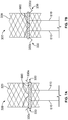
- FIGS. 8A-B illustrate an alternate embodiment of a cell 330' nested within cell 324 of stent 320 in the expanded condition and the collapsed condition, respectively, with the remainder of prosthetic heart valve 300 omitted for clarity.
- proximal struts 330b' and 330d' connect to cell 324 at connection points 332' and 334', respectively.
- Connection points 332' and 334' may be thicker than connection points 332 and 334 of nested cell 330.
- connection points 332 and 334 may need to be relatively thin to allow for the requisite twisting of the connection points. However, this twisting may create a relatively large amount of torsion and/or stress on connection points 332 and 334, which may be undesirable.
- Connection points 332' and 334' may be thicker to reduce the torsion and/or stresses on the connection points, but this may also reduce or eliminate the ability of connection points 332' and 334' to twist to create the pivoting motion described in connection to cell 330'.
- connection points 332' and 334' can be achieved with thick connection points 332' and 334' by attaching distal struts 330a' and 330c' directly to proximal struts 330d' and 330b', respectively, rather than to connection points 332' and 334'.
- proximal strut 330d' connects to distal strut 330a' at first connection point 333' spaced proximally of connection point 332', while proximal strut 330b' connects to distal strut 330c' at second connection point 335' spaced proximally of connection point 334'.
- first connection point. 333' and second connection point 335' also move toward the plane of cell 324. Because distal struts 330a' and 330c' extend from first connection point 333' and second connection point 335', respectively, distal struts 330a' and 330c' rotate radially outward from the plane of cell 324 as proximal struts 330b' and 330c' move toward the plane of cell 324. This motion is illustrated in FIGS. 8C-E .
- distal struts 330a' and 330c' may be capable of rotating or pivoting a relatively large distance from the plane of cell 324.
- proximal struts 330b' and 330d' may be shorter in the axial or length direction than distal struts 330a' and 330c', without significantly affecting the shape of cell 324.
- connection points 332' and 334' are positioned substantially at the midline of cell 324, while the connection points 333' and 335' are axially offset from the connection points 332' and 334'.
- proximal struts 330b' and 330d' when in the collapsed condition, proximal struts 330b' and 330d' have an axial length of L 2 which is less than the axial length L 1 of distal struts 330a' and 330c'.
- proximal struts 330b' and 330d' may be shape-set such that, in the absence of applied force, they each extend radially outwardly from prosthetic heart valve 300.
- Distal struts 330a' and 330c' may be shape-set such that, in the absence of applied force, they each generally align within the cylindrical shape of stent 320.
- the smaller axial length L 2 of proximal struts 330b' and 330d' compared to the axial length L 1 of distal struts 330a' and 330c' may provide a greater amount of pivoting than might be seen if the axial length of the proximal struts and distal struts were equal. This additional pivoting motion may facilitate clamping of the native mitral valves.
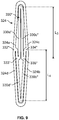
- FIG. 9 illustrates another embodiment of a cell 330" nested within cell 324 in a collapsed configuration.
- Nested cell 330" is similar to nested cell 330' in a number of ways.
- distal strut 330a" connects to proximal strut 330d" at first connection point 333"
- distal strut 330c connects to proximal strut 330b" at second connection point 335" .
- proximal strut 330d connects to cell 324 at connection point 332" and proximal strut 330b" connects to cell 324 at connection point 334",
- connection points 332" and 334" are not positioned substantially at the midline of cell 324, but are rather connected to proximal struts 324a and 324c, respectively.
- proximal struts 330b" and 330d" have an axial length L 4 that is substantially the same as the axial length L 3 of distal struts 330a" and 33c" .
- An exemplary method of delivering a prosthetic heart valve into a patient comprises: loading the prosthetic heart valve into a delivery device in a collapsed condition, the delivery device including a sheath extending from a proximal end to a distal end, the prosthetic heart valve including a stent extending in an axial direction from a proximal end to a distal end and having a plurality of first cells, each first cell having an open space defined by a first plurality of struts, and a second cell nested in the open space of one of the first cells, the second cell being defined by a second plurality of struts; advancing the sheath to an implant site within the patient; retracting the sheath with respect to the prosthetic heart valve until at least a portion of the second cell is positioned outside of the sheath; and pivoting the second cell with respect to the one of the first cells to create a clearance space between the second cell and an outer perimeter of the stent; and/or
Landscapes
- Health & Medical Sciences (AREA)
- Cardiology (AREA)
- Engineering & Computer Science (AREA)
- Biomedical Technology (AREA)
- Heart & Thoracic Surgery (AREA)
- Transplantation (AREA)
- Oral & Maxillofacial Surgery (AREA)
- Vascular Medicine (AREA)
- Life Sciences & Earth Sciences (AREA)
- Animal Behavior & Ethology (AREA)
- General Health & Medical Sciences (AREA)
- Public Health (AREA)
- Veterinary Medicine (AREA)
- Prostheses (AREA)
Description
- The present disclosure relates to heart valve replacement and, in particular, to collapsible prosthetic heart valves. More particularly, the present disclosure relates to devices and methods for securing collapsible prosthetic heart, valves within native valve annuluses.
- Prosthetic heart valves that are collapsible to a relatively small, circumferential size can be delivered into a patient less invasively than valves that are not collapsible. For example, a collapsible valve may be delivered into a patient via a tube-like delivery apparatus such as a catheter, a trocar, a laparoscopic instrument, or the like. This collapsibility can avoid the need for a more invasive procedure such as full open-chest, open-heart surgery.
- Collapsible prosthetic heart valves typically take the form of a valve structure mounted on a stent. There are two types of stents on which the valve structures are ordinarily mounted: a self-expanding stent and a balloon-expandable stent. To place such valves into a delivery apparatus and ultimately into a patient, the valve is generally first collapsed or crimped to reduce its circumferential size.
- When a collapsed prosthetic valve has reached the desired implant site in the patient (e.g., at or near the annulus of the patient's heart valve that is to be replaced by the prosthetic valve) , the prosthetic valve can be deployed or released from the delivery apparatus and. re-expanded to full operating size. For balloon-expandable valves, this generally involves releasing the entire valve, assuring its proper location, and then expanding a balloon positioned, within the valve stent. For self-expand i.ng valves, on the other hand, the stent automatically expands as the sheath covering the valve is withdrawn.
-
WO 2011/002996 andWO 2008/002441 both disclose collapsible and expandable stents. - According to one embodiment of the disclosure, there is provided a prosthetic heart valve comprising: a collapsible and expandable stent extending in an axial direction from an outflow end to an inflow end, comprising: a plurality of first cells, each first cell having an open space defined by a first plurality of struts; a second cell nested in the open space of one of the first cells, the second cell being defined by a second plurality of struts; and first and second connecting struts connecting the second cell to the one of the first cells; wherein the second cell is configured to pivot about the first and second connecting struts with respect to the one of the first cells, and a collapsible and expandable valve assembly disposed within the stent and having a plurality of leaflets; characterized by the one of the first cells defining a surface and the second cell including first and second struts that do not lie within the surface when no external force is applied to the stent.
- Various embodiments of the present disclosure are described herein with reference to the drawings, wherein:
-
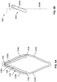
FIG. 1 is a schematic cutaway representation of a human heart showing a transapical delivery approach; -
FIG. 2 is a schematic representation of a native mitral valve and associated cardiac structures; -
FIG. 3A is a partial front view of a prosthetic heart valve according to an embodiment of the disclosure; -
FIG. 3B is an enlarged isolated front view of a nested cell in an expanded condition within another cell of the prosthetic heart valve ofFIG. 3A ; -
FIG. 3C is an enlarged isolated front view of the nested cell ofFIG. 3B in a collapsed condition; -
FIG. 3D is an enlarged isolated side view of the nested cell ofFIG. 3B pivoted with respect to the other cell; -
FIG. 4A is an enlarged isolated side view of the nested cell of FIG. 33 in an expanded condition after being shape-set; - FIG. 48 is a longitudinal cross-section a prosthetic heart valve incorporating a plurality of nested cells of
FIG. 4A in an expanded condition; -
FIG. 4C is a longitudinal cross-section of the prosthetic heart valve ofFIG. 4B being deployed from the delivery device; -
FIG. 4D is a longitudinal cross-section of the prosthetic heart valve ofFIG. 4B in a collapsed condition partially within a delivery device; -
FIG. 4E is a partial schematic representation of the prosthetic heart valve ofFIG. 4B disposed in a native valve annulus; -
FIG. 4F is a partial schematic representation of another embodiment of a prosthetic heart valve disposed in an native valve annulus; -
FIG. 5A is an enlarged isolated front view of an example of a nested partial cell in an expanded condition within another cell of a prosthetic heart valve; -
FIG. 5B is an enlarged isolated side view of the nested cell ofFIG. 5A in an expanded condition after being shape-set; -
FIG. 5C is a longitudinal cross-section a prosthetic heart valve incorporating the nested cell ofFIG. 5A in an expanded condition; -
FIG. 5D is a longitudinal cross-section of the prosthetic heart valve ofFIG. 5C in a collapsed condition within a delivery device; -
FIG. 5E is a longitudinal cross-section of the prosthetic heart valve ofFIG. 5C being deployed from the delivery device; -
FIG. 6A is a longitudinal cross-section of a prosthetic heart valve in a collapsed condition within a delivery device according to another embodiment of the disclosure; -
FIG. 6B is a longitudinal cross-section of the delivery device ofFIG. 6A with a resheathing member in an extended position; -
FIG. 6C is a longitudinal cross-section of the prosthetic heart valve ofFIG. 6A partially within the delivery device ofFIG. 6A with the resheathing member in an extended position; -
FIG. 7A is a longitudinal cross-section a prosthetic heart valve with a resheathing member in a first position; -
FIG. 7B is a longitudinal cross-section of the prosthetic heart valve ofFIG. 7A with the resheathing member in a second position; -
FIG. 8A is an enlarged isolated front view of an embodiment of a nested cell in an expanded condition within another cell of a prosthetic heart valve; -
FIG. 8B is an enlarged isolated front view of the nested cell ofFIG. 8A within the other cell of the prosthetic heart valve in a collapsed condition; -
FIGS. 8C-E are enlarged isolated perspective views of the nested cell ofFIG. 8A in different stages of pivoting with respect to the other cell of the prosthetic heart valve in the collapsed condition; and -
FIG. 9 is an enlarged isolated front view of another embodiment of a nested cell in a collapsed condition within another cell of a prosthetic heart valve. - In conventional collapsible heart valves, the stent is usually anchored within the native valve annulus via the radial force exerted by the expanding stent against the native valve annulus. If the radial force is too high, damage may occur to heart tissue. If, instead, the radial force is too low, the heart valve may move from its implanted position. For prosthetic mitral valves, for example, the implanted valve may move into either the left ventricle or the left atrium, requiring emergency surgery to remove the displaced valve. Moreover, in certain applications, such as mitral valve replacement, the heart valve may require a lower profile so as not to interfere with surrounding tissue structures. Such a low profile may make it difficult for the valve to remain in place. Other designs may include hooks or similar features that passively engage tissue until tissue ingrowth is established.
- In view of the foregoing, there is a need for further improvements to the devices, systems, and methods for prosthetic heart valve implantation and the anchoring of collapsible prosthetic heart valves, and in particular, self-expanding prosthetic heart valves. Among other advantages, the devices, systems and methods of the present disclosure may address one or more of these needs,
- Blood flows through the mitral valve from the left atrium to the left ventricle. As used herein, the term "inflow end," when used in connection with a prosthetic mitral heart valve, refers to the end of the heart valve closest to the left atrium when the heart valve is implanted in a patient, whereas the term "outflow end," when used in connection with a prosthetic mitral heart valve, refers to the end of the heart valve closest to the left ventricle when the heart valve is implanted in a patient. Further, when used herein with reference to a delivery device, the terms "proximal" and "distal." are to be taken as relative to a user using the device in an intended manner. "Proximal" is to be understood as relatively close to the user and "distal" is to be understood as relatively farther away from the user. Also, as used herein, the terms "substantially," "generally," and "about" are intended to mean that slight deviations from absolute are included within the scope of the term so modified.
-
FIG. 1 is a schematic cutaway representation ofhuman heart 100.Heart 100 includes two atria and two ventricles:right atrium 112 andleft atrium 122, andright ventricle 114 andleft ventricle 124.Heart 100 further includesaorta 110, andaortic arch 120. Disposed betweenleft atrium 122 andleft ventricle 124 ismitral valve 130.Mitral valve 130, also known as the bicuspid valve or left atrioventricular valve, is a dual-flap that opens as a result of increased pressure inleft atrium 122 as it fills with blood. As atrial pressure increases above that ofleft ventricle 124,mitral valve 130 opens and blood passes intoleft ventricle 124. Blood flows throughheart 100 in the direction shown by arrows "B". - A dashed arrow, labeled "TA", indicates a transapical approach of implanting a prosthetic heart valve, in this case to replace the mitral valve. In transapical delivery, a small incision is made between the ribs and into the apex of
left ventricle 124 to deliver the prosthetic heart valve to the target site. A second dashed arrow, labeled "TS", indicates a transseptal approach of implanting a prosthetic heart valve in which the valve is passed through the septum betweenright atrium 112 andleft atrium 122. Other percutaneous approaches for implanting a prosthetic heart valve are also contemplated herein. -
FIG. 2 is a more detailed schematic representation of nativemitral valve 130 and its associated structures. As previously noted,mitral valve 130 includes two flaps or leaflets, posterior leaflet. 136 andanterior leaflet 138, disposed betweenleft atrium 122 andleft ventricle 124. Cord-like tendons, known aschordae tendineae 134, connect the twoleaflets papillary muscles 132. During atrial systole, blood flows from higher pressure in left atrium. 122 to lower pressure inleft ventricle 124. Whenleft ventricle 124 contracts in ventricular systole, the increased blood pressure in the chamber pushesleaflets left atrium 122. Since the blood pressure inleft atrium 122 is much lower than that inleft ventricle 124,leaflets Chordae tendineae 134 prevent the eversion by becoming tense, thus pulling onleaflets -
FIG. 3A is a side view ofprosthetic heart valve 300 in accordance with one embodiment of the present disclosure.FIG. 3A illustratesprosthetic heart valve 300 in a relaxed condition.Prosthetic heart valve 300 is a collapsible prosthetic heart valve designed to replace the function of the native mitral valve of a patient (see nativemitral valve 130 ofFIGS. 1-2 ). Generally,prosthetic valve 300 hasinflow end 310 andoutflow end 312.Prosthetic valve 300 may have a substantially cylindrical shape and may include features for anchoring it to native heart tissue, as will be discussed in more detail below. When used to replace nativemitral valve 130,prosthetic valve 300 may have a low profile so as not to interfere with atrial function in the native valve annulus. -
Prosthetic heart valve 300 may includestent 320, which may be formed from biocompatible materials that are capable of self-expansion, such as, for example, shape memory alloys including Nitinol.Stent 320 may include a plurality ofstruts 322 that formcells 324 connected to one another in one or more annular rows around the stent. Generally,cells 324 may all be of substantially the same size around the perimeter and along the length ofstent 320. Alternatively,cells 324 nearinflow end 310 may be larger than the cells nearoutflow end 312.Stent 320 may be expandable to provide a radial force to assist with positioning and stabilizingprosthetic heart valve 300 in the native valve annulus. -
Prosthetic heart valve 300 may also include a generallycylindrical cuff 326 which may facilitate attachment of a valve assembly, described in more detail below, tostent 320.Cuff 326 may be attached to at least somestruts 322, for example withsutures 328. -
Stent 320 include one or morenested cells 330.Nested cells 330 may facilitate the clamping of a native valve leaflet, such asposterior leaflet 136 and/oranterior leaflet 138 ofmitral valve 130, upon implantation ofprosthetic valve 300. Onenested cell 330 is illustrated in greater detail inFIGS. 3B-D . In particular,FIGS. 3B-C illustratecell 330 nested within acell 324 ofstent 320 in the expanded condition and the collapsed condition, respectively, with the remainder ofprosthetic heart valve 300 omitted. In this embodiment,cell 324 may be thought of as being formed of four struts, including a first pair of generallyparallel struts 324a-b and a second pair of generallyparallel struts 324c-d. In the aggregate, struts 324a-d form generally a diamond shape when in the expanded condition.Nested cell 330 has a shape similar tocell 324, and may also be thought of as being formed of fourstruts 330a-d, with a first pair of generallyparallel struts 330a-b and a second pair of generallyparallel struts 330c-d that, in the aggregate, form generally a diamond shape when in the expanded condition.Cell 330, defined bystruts 330a-d, is nested substantially within the perimeter of thestruts 324a-d forming cell 324. -
Nested cell 330 is connected tocell 324 by connectingstruts struts cell 324 to nestedcell 330 along a midline M of the cells. In this configuration, nestedcell 330 may rotate or pivot about connectingstruts cell 324, as described below. For example, a side view ofcell 324 and nestedcell 330 in the collapsed condition is illustrated inFIG. 3D .Nested cell 330 is shown as rotated with respect tocell 324 about connectingstruts 332 and 334 (not visible inFIG. 3D ). - The ability of nested
cell 330 to rotate with respect tocell 324, in combination with the shape memory property ofstent 320, may help provide a number of different actions of nestedcell 330 during delivery and deployment ofprosthetic valve 300. For example,FIG. 4A illustrates nestedcell 330, withcell 324 in phantom lines and the remainder ofprosthetic heart valve 300 omitted. In this configuration, nestedcell 330 is illustrated after it has been shape-set, for example by heat setting, so thatstruts FIG. 4A ) are angled radially outwardly with respect tostruts FIG. 4A ). The term "angled radially outwardly" includes substantially straight flaring in the radially outward direction as well as a curved flaring in the radially outward direction. With this shape setting, nestedcell 330 tends to revert to the illustrated condition when no external forces are applied tostent 320. One benefit of this particular configuration becomes clearer when viewed in the context of the use of a pair of nestedcells 330 with asheath 390 of a mitral valve delivery device. -
FIG. 4B illustrates a longitudinal cross-sectional view ofprosthetic heart valve 300 in the expanded condition. In this embodiment,prosthetic heart valve 300 may also include a substantiallycylindrical valve assembly 360 including a pair ofleaflets FIG. 3A ).Leaflets mitral valve leaflets FIG. 2 . That is,leaflets Leaflets Stent 320 may include a pair of nestedcells 330 substantially diametrically opposed to one another. Each of nestedcells 330 is shape-set as described in connection withFIG. 4A . As illustrated inFIG. 4B ,proximal struts stent 320.Distal struts stent 320, so that they are not readily visible inFIG. 4B . -
FIG. 4C is a longitudinal cross-sectional view ofprosthetic valve 300 in a collapsed condition and loaded intosheath 390 of a delivery device. Mitral valve delivery devices are known in the art andonly sheath 390 is illustrated to facilitate the explanation of a function of nestedcells 330.Sheath 390 may be in the form of a generally cylindrical tube extending from a proximal end (not illustrated) to adistal end 392. Althoughdistal end 392 ofsheath 390 is illustrated as an open end, additional structure would generally be provided along with the remainder of the delivery device to allowdistal end 392 to be closed during delivery. During replacement of nativemitral valve 130 withprosthetic valve 300,prosthetic valve 300 is first crimped or otherwise collapsed and secured neardistal end 392 ofsheath 390. Although a gap is shown between the outer diameter ofprosthetic heart valve 300 and the inner diameter ofsheath 390, this is meant to provide clarity and, in practice, some, if not all, ofstent 320 ofprosthetic heart valve 330 would be in direct, contact, with the inner surface ofsheath 390. This contact restrictsprosthetic heart valve 300 from expanding, while simultaneously causing nestedcells 330 to be generally aligned with the outer circumference ofstent 320. In other words, althoughproximal struts cell 330 are shape-set to extend radially outwardly fromstent 320, the inner diameter ofsheath 390 constrainsproximal struts proximal struts 330b and 300d creates a rotational stress in connectingstruts cell 330 is constrained from rotating radially outwardly while withinsheath 390, this rotational force on connectingstruts struts 330a-d. - During delivery of
prosthetic valve 300, for example by a transapical route to nativemitral valve 130,distal end 392 of the delivery device is advanced until it is near the site of implantation. Once positioned as desired,sheath 390 is retracted proximally relative toprosthetic heart valve 300, as illustrated inFIG. 4D . As the retraction of the sheath continues, more ofprosthetic heart valve 300 is exposed, reducing the constraint caused by the sheath. As this constraint is reduced or released,stent 320 begins to revert to its shape-set expanded condition (not shown inFIG. 4D ) . Asdistal end 392 ofsheath 390 begins to retract proximally past nestedcells 330, the stored rotational stress in connectingstruts distal struts struts struts distal struts stent 320. During deployment ofprosthetic heart valve 300 within the annulus of nativemitral valve 130,prosthetic heart valve 300 may be positioned relative to the native mitral valve such thatposterior leaflet 136 andanterior leaflet 138 ofmitral valve 130 are each positioned in one of these clearance spaces. For example, this may be accomplished by advancingprosthetic heart valve 300 distally once the clearance space has been created. Assheath 390 is retracted further proximally beyond the remainder of nestedcells 330, the stored rotational stress in connectingstruts cells 330 to attempt to revert back to the shape-set configuration illustrated inFIG. 4A . - If
prosthetic valve 300 is positioned properly, as nestedcells 330 attempt to revert back to their original shape-set configuration,posterior leaflet 136 will be clamped betweenstent 320 anddistal struts anterior leaflet 138 will be clamped betweenstent 320 and the distal struts of the other nested cell, as illustrated inFIG. 4E . It should be noted that, if not positioned properly,prosthetic heart valve 300 may be resheathed intosheath 390 as long as nestedcells 330 have not been fully exposed. If nestedcells 330 were fully exposed,proximal struts stent 320 to retract back intosheath 390. Rather,distal end 392 ofsheath 390 would catch on protrudingproximal struts prosthetic heart valve 300 to nativemitral valve 130. Other known mechanisms for securing a prosthetic valve to a native valve may provide less robust connections, which may result in relative motion between the prosthetic valve and the native valve during in vivo operation, particularly during the time period prior to tissue ingrowth. The above-described clamping mechanism, on the other hand, may reduce or eliminate relative motion betweenprosthetic heart valve 300 and nativemitral valve 130 from the moment of implantation. - A number of other components known for use with prosthetic valves may be provided but have not been illustrated herein for clarity. For example, the embodiment of
prosthetic valve 300 described above for use in replacement of nativemitral valve 130 may include abraided seal 395, illustrated inFIG. 4F , that facilitates holdingprosthetic valve 300 on the atrial side of the mitral valve annulus. This and other types of braided stents are described more fully in, for example,U.S. Provisional Patent Application No. 61/836,427 - Similarly, a number of variations of the components described above are still within the scope of the present disclosure. For example, although a prosthetic heart valve has been described with two nested cells on substantially diametrically opposite portions of the prosthetic valve, more or fewer nested cells may be provided. For example, one, three, four or more nested cells may be used as desired. Generally, it may be useful to use a number of nested cells at least equal to the number of leaflets in the native valve to be replaced. For example, at least three nested cells may be particularly useful for a prosthetic heart valve that is to replace a tricuspid or aortic valve. However, it should be understood that any number of nested cells may be appropriate for a valve with any number of native leaflets, and the nested cells need not be equally spaced around the circumference of the prosthetic valve. Further, although struts of the nested cell are described as "angled" radially outward, this also includes a configuration in which struts are curved outwardly. An outward curve may be less likely to dig into an inner wall of a delivery device when the stent is in the collapsed condition compared to a straight angle. For example, a small or slight curve at the end of a nested cell may reduce the tendency of the nested cell to dig into the delivery device during delivery, and may also help minimize deployment forces.
- A
partial cell 430 nested within acell 424 of aprosthetic heart valve 400 in the expanded condition is illustrated inFIG. 5A . InFIG. 5A ,only cell 424 and nestedpartial cell 430 are illustrated. In this example, not falling within the scope of the claims, as inprosthetic heart valve 300,cell 424 may be thought of as being formed of four struts, including a first pair of generallyparallel struts 424a-b and a second pair of generallyparallel struts 424c-d. In the aggregate, struts 424a-d form generally a diamond shape when in the expanded condition. Nestedpartial cell 430, however, takes the form of a half or partial cell, generally following a shape similar to the upper or distal half ofcell 424. Nestedpartial cell 430 may be thought of as being formed of twostruts prosthetic heart valve 300, nestedpartial cell 430 may be connected tocell 424 by connectingstruts partial cell 430 may rotate or pivot about connectingstruts cell 424. In addition, nestedpartial cell 430 may include a through hole, such as an aperture oreyelet 435.Eyelet 435 may be positioned at a distal end of nestedpartial cell 430 wherestrut 430a meetsstrut 430c, but other positioning may be acceptable. As is described below, in certain embodiments,eyelet 435 enables a user to manipulate nestedpartial cell 430 during valve deployment. -
FIG. 5B illustrates nestedpartial cell 430 after it has been shape-set in one particular configuration withcell 424 in phantom lines and the remainder ofprosthetic heart valve 400 omitted. In this configuration,distal struts FIG. 5B ) are angled radially inwardly with respect tocell 424. With this shape setting, nestedpartial cell 430 tends to revert to the illustrated condition when no external forces are applied. -
FIG. 5C illustrates a longitudinal cross-sectional view ofprosthetic heart valve 400 in the expanded condition.Prosthetic heart valve 400 may be the same asprosthetic heart valve 300 in all respects other than nestedpartial cells 430.Stent 420 ofprosthetic heart valve 400 may include a pair of nestedpartial cells 430 substantially diametrically opposed to one another. Nestedpartial cells 430 are each shape-set as described in connection withFIG. 5B . As illustrated inFIG. 5C , distal struts 430a. and 430c extend radially inwardly and distally fromstent 420. -
FIG. 5D is a longitudinal cross-sectional view ofprosthetic valve 400 in a collapsed condition and loaded intosheath 490 of a delivery device.Sheath 490 may be substantially the same assheath 390, having the form of a generally cylindrical tube extending from a proximal end (not illustrated) to adistal end 492. The delivery system may also include one or more connectors, such as pull wires or sutures S, connected to eyelets 435 (seeFIG. 5A ) of nestedpartial cells 430. Each suture S may be threaded through acorresponding eyelet 435 to form a loop at the distal end of each nestedpartial cell 430 with two strands of the suture extending proximally throughsheath 490. Sutures S may extend proximally, preferably between the outer circumference ofprosthetic valve 400 and the inner circumference ofsheath 490, so that their proximal ends are positioned outside the patient for manipulation by the user. Although sutures S are illustrated as freely extending proximally, it should be understood that other structures, such as guide lumens, may be used in conjunction with sutures S. In a variant hereof,partial cell 430 may not be provided with anyeyelets 435. In such variant, a length of suture S may be looped around one or more ofstruts partial cell 430, with the two strands of the suture extending proximally throughsheath 490. - As
prosthetic valve 400 is deployed, typically by retractingsheath 490, nestedpartial cells 430 become clear of the constraint ofsheath 490. Once nestedpartial cells 430 are clear ofsheath 490, the user may manipulate sutures S, for example by manually pulling them proximally, to cause nestedpartial cells 430, and particularlydistal struts FIG. 5E , creating clearance spaces between the distal struts and the outer perimeter of the remainder ofstent 420. As described in relation to previous embodiments, once nestedpartial cells 430 extend radially outwardly,prosthetic heart valve 400 may be positioned so thatposterior leaflet 136 andanterior leaflet 138 of nativemitral valve 130 are each positioned in one of these clearance spaces. Once in the desired position, the user may release tension on sutures S so thatdistal struts prosthetic valve 400 is positioned properly,posterior leaflet 136 will be clamped betweenstent 420 anddistal struts anterior leaflet 138 will be clamped betweenstent 420 and the distal struts of the other nested partial. - It should be noted that, if
prosthetic valve 400 is not positioned properly, the user may again pull sutures S proximally to movedistal struts partial cells 430 andprosthetic heart valve 400 has not been entirely released fromsheath 490,prosthetic heart valve 400 may be resheathed if desired. Once nestedpartial cells 430 are clamped in a desired position, the user may pull one strand of each suture S proximally to remove sutures S from the patient. - It should be understood that variations may be made to
prosthetic heart valve 400 described above. For example, althoughdistal struts distal struts stent 420 when no force is applied. Also,eyelet 435 may be replaced with other structures that may provide similar functionality. For example, struts 430a and/or 430c may have ridges, flanges, extensions, or other structures around which sutures S are wrapped. However,eyelet 435 may provide for a more secure connection to sutures S than these alternatives. Additionally, although sutures S are described as being manipulated manually by a user, sutures S may be connected at their proximal ends to other structures, such as a sliding mechanism in a handle of the delivery device, to facilitate proximal and distal movement of sutures S. Similarly, sutures S may be attached to nestedpartial cells 430 without the use of aneyelet 435. Still further, a full cell, such ascell 330 described in connection toFIG. 3B , may be used with an eyelet in a similar fashion as described in connection to nestedpartial cell 430. -
FIG. 6A is a longitudinal cross-sectional view ofprosthetic valve 300 in a collapsed condition and loaded intosheath 590 of a delivery device.Prosthetic valve 300 is the same as that described in connection withFIGS. 3A-4B and with nestedcells 330 shape-set as described in connection withFIG. 4A .Sheath 590 may be substantially the same assheaths distal end 592. The delivery system may also include one or more resheathing members, such asarms 595. Eacharm 595 may extend from the proximal end ofsheath 590 towarddistal end 592. InFIG. 6A ,arms 595 are illustrated in a proximal or retracted condition in which a distal end of each arm is positioned withinsheath 590, preferably between the outer circumference ofprosthetic valve 300 and the inner circumference ofsheath 590. The proximal end of eacharm 595 may extend far enough proximally to be positioned outside the patient's body so that a user may manipulate eacharm 595, for example by pushing or pulling the arm. Thearms 595 may alternately be connected to a handle or other portion of the delivery device to facilitate manipulation of the arms. - The structure of
arms 595 is best illustrated inFIG. 6B , which illustratessheath 590 witharms 595 in a distal or extended condition, withprosthetic valve 300 omitted from the figure.Arms 595 may be transitioned from the retracted condition shown inFIG. 6A to the extended condition shown inFIG. 6B by proximal movement ofsheath 590 relative toarms 595, for example by retraction ofsheath 590 with respect toarms 595. Thedistal portion 596 of eacharm 595 may include an outwardly flaredsegment 597 with afinger 598 canted radially inward at its distal end. Eacharm 595 may be formed of a shape-memory alloy such as Nitinol shape-set such thatdistal portion 596 takes the illustrated shape upon transitioning to the extended condition. Whilearms 595 take this shape when in the extended condition,arms 595, includingdistal portion 596, are substantially linear when in the retracted condition. - The function of
arms 595 is best illustrated with respect toFIG. 6C , which showssheath 590 witharms 595 in the extended condition along withprosthetic valve 300 in a partially expanded condition. In particular,sheath 590 has been retracted such thatprosthetic valve 300 takes a similar form as illustrated inFIG. 4B , withproximal struts distal end 592 ofsheath 590. However, unlike the fully expanded condition illustrated inFIG. 4B ,prosthetic valve 300 is only partially expanded inFIG. 6C . At this point, ifprosthetic valve 300 is positioned properly,distal struts cell 330 will have clamped one of the native mitral valve leaflets. If the position is satisfactory, the user may withdrawarms 595 until thedistal portion 596 of each arm is positioned withinsheath 590, at which point the delivery device may be removed from the patient. However, if the position ofprosthetic valve 300 is not satisfactory, the user may advancesheath 590 distally with respect toprosthetic valve 300, keepingarms 595 stationary relative to the prosthetic valve. Assheath 590 advances distally, it compresses or flattens flaredsegments 597 andfingers 598 ofarms 595 inwardly, which in turn causesproximal struts cells 330 to compress inwardly toward the remainder ofstent 320. Oncesheath 590 surroundsproximal struts distal struts prosthetic heart valve 300 as desired. -
FIG. 7A is a longitudinal cross-sectional view ofprosthetic heart valve 300 in the expanded condition along with a position controlling component, with nestedcells 330 shape-set as described in connection withFIG. 4A . The position controlling component may be in the form of aband 600, for example. Band 600 may be a strip of material, such as a fabric or a shape-memory alloy, that encirclesprosthetic heart valve 300. In particular,band 600 may be positioned at or close to the point at whichdistal struts cells 330 transition toproximal struts band 600 may be positioned such that it extends generally across midline M of nestedcells 330 and connectingstruts 332 and 334 (Fig. 3B ) which act as pivot points for nestedcells 330. - Band 600 may include one, two, or
more connectors 610.Connectors 610 may be push/pull wires having sufficient strength and stiffness to transmit force to band 600 in both a pulling (proximal) and pushing (distal) direction. Eachconnector 610 has a distal end operatively attached toband 600, a proximal end (not illustrated), and a length such that, whenprosthetic heart valve 300 is at the site of implantation, the proximal end of eachconnector 610 lies outside the patient's body and may be manipulated by the user. The proximal end of eachconnector 610 may be free for manual manipulation, or attached to a handle or other portion of the delivery device, such as a slider, to facilitate manipulation ofconnectors 610. The distal ends of eachconnector 610 may be threaded, for example, with a corresponding connector portion onband 600 also being threaded. - The delivery of
prosthetic valve 300 withband 600 may be accomplished mostly identically to the procedure described in connection withFIGS. 4C-E . During delivery ofprosthetic valve 300,band 600 is in a first position, at or close to the point at whichdistal struts cells 330 transition toproximal struts proximal struts prosthetic valve 300, the prosthetic valve begins to expand to its circumferential shape. Band 600 will also begin to take a circumferential shape, either by self-expansion or due to expansion ofprosthetic heart valve 300 which the band encircles. - After
prosthetic valve 300 has been partially released from a sheath (not illustrated inFIG. 7A ), such that a portion ofprosthetic valve 300 remains within the sheath but nestedcells 330 are clear of the sheath,distal struts FIG. 7A . This is possible becauseband 600 encirclesproximal struts distal struts prosthetic heart valve 300. The user may then advanceband 600 distally with respect tostent 320 usingconnectors 610. Asband 600 advances distally to a second position, it encirclesdistal struts 300a and 330c, causing them to pivot inwardly and clamp the native leaflets, as shown inFIG. 7B . - If at this point the positioning of
prosthetic heart valve 300 is not to the user's satisfaction, the user may pullconnectors 610 proximally, resulting in the proximal movement ofband 600 back to the first position. Asband 600 moves proximally relative toprosthetic heart valve 300, it forcesproximal struts distal struts prosthetic heart valve 300 may be resheathed, and deployment ofprosthetic valve 300 may be attempted again. Once a satisfactory deployment has been completed, the user may unscrewconnectors 610 fromband 600 by rotating them. Once disconnected,connectors 610 and the remainder of the delivery system may be removed from the patient, leavingprosthetic heart valve 300, along withband 600, permanently implanted in the patient. - Although nested
cells FIGS. 8A-B illustrate an alternate embodiment of a cell 330' nested withincell 324 ofstent 320 in the expanded condition and the collapsed condition, respectively, with the remainder ofprosthetic heart valve 300 omitted for clarity. In this embodiment,proximal struts 330b' and 330d' connect tocell 324 at connection points 332' and 334', respectively. Connection points 332' and 334' may be thicker than connection points 332 and 334 of nestedcell 330. For connection points 332 and 334 to act as pivot points, the material forming the connection points may need to be relatively thin to allow for the requisite twisting of the connection points. However, this twisting may create a relatively large amount of torsion and/or stress onconnection points distal struts 330a' and 330c' directly toproximal struts 330d' and 330b', respectively, rather than toconnection points 332' and 334'. - As noted above,
proximal strut 330d' connects todistal strut 330a' atfirst connection point 333' spaced proximally ofconnection point 332', whileproximal strut 330b' connects todistal strut 330c' at second connection point 335' spaced proximally of connection point 334'. Once shape-set, for example in a similar manner as described in connection withFIG. 4A , radially inward pivoting or compression ofproximal struts 330b' and 330d' cause those struts to rotate, or pivot, about connection points 332' and 334'. However, because of the thickness of connection points 332' and 334', they experience relatively little twisting and low stresses. Further, asproximal struts 330b' and 330d' are compressed or pivoted radially inwardly, first connection point. 333' and second connection point 335' also move toward the plane ofcell 324. Becausedistal struts 330a' and 330c' extend fromfirst connection point 333' and second connection point 335', respectively,distal struts 330a' and 330c' rotate radially outward from the plane ofcell 324 asproximal struts 330b' and 330c' move toward the plane ofcell 324. This motion is illustrated inFIGS. 8C-E . - In the particular embodiment illustrated in
FIGS. 8A-E ,distal struts 330a' and 330c' may be capable of rotating or pivoting a relatively large distance from the plane ofcell 324. By movingconnection points 333' and 335' proximally of connection points 332' and 334',proximal struts 330b' and 330d' may be shorter in the axial or length direction thandistal struts 330a' and 330c', without significantly affecting the shape ofcell 324. In other words, connection points 332' and 334' are positioned substantially at the midline ofcell 324, while the connection points 333' and 335' are axially offset from the connection points 332' and 334'. As illustrated inFIG. 8B , when in the collapsed condition,proximal struts 330b' and 330d' have an axial length of L2 which is less than the axial length L1 ofdistal struts 330a' and 330c'. - As noted above,
proximal struts 330b' and 330d' may be shape-set such that, in the absence of applied force, they each extend radially outwardly fromprosthetic heart valve 300. Distal struts 330a' and 330c' may be shape-set such that, in the absence of applied force, they each generally align within the cylindrical shape ofstent 320. During deployment ofprosthetic valve 300 in a manner similar or identical to that described in connection withFIGS. 4C-E , the smaller axial length L2 ofproximal struts 330b' and 330d' compared to the axial length L1 ofdistal struts 330a' and 330c' may provide a greater amount of pivoting than might be seen if the axial length of the proximal struts and distal struts were equal. This additional pivoting motion may facilitate clamping of the native mitral valves. - It should be understood that, when using relatively thick connection points between a first cell and a second cell nested within the first cell, the configuration may vary from that described in connection with
FIGS. 8A-E . For example,FIG. 9 illustrates another embodiment of acell 330" nested withincell 324 in a collapsed configuration.Nested cell 330" is similar to nested cell 330' in a number of ways. For example,distal strut 330a" connects toproximal strut 330d" atfirst connection point 333" , whiledistal strut 330c" connects toproximal strut 330b" atsecond connection point 335" . Further,proximal strut 330d" connects tocell 324 atconnection point 332" andproximal strut 330b" connects tocell 324 atconnection point 334", However, in this embodiment, connection points 332" and 334" are not positioned substantially at the midline ofcell 324, but are rather connected toproximal struts proximal struts 330b" and 330d" have an axial length L4 that is substantially the same as the axial length L3 ofdistal struts 330a" and 33c" . As should be apparent, a variety of configurations may be possible to suit a particular purpose without deviating from the concepts disclosed herein. - According to one embodiment of the disclosure, a collapsible and expandable stent extending in an axial direction from a proximal end to a distal end comprises: a plurality of first cells, each first cell having an open space defined by a first plurality of struts; a second cell nested in the open space of one of the first cells, the second cell being defined by a second plurality of struts; and first and second connecting struts connecting the second cell to the one of the first cells; wherein the second cell is configured to pivot about the first and second connecting struts with respect to the one of the first cells; and/or
- a pulling member operably connected to at least one of the second plurality of struts; and/or
- an aperture in the at least one of the second plurality of struts, the pulling member being threaded through the aperture; and/or
- the second plurality of struts includes a first strut, a second strut, a third strut, and a fourth strut, the first and second struts each being positioned closer to the proximal end of the stent than the third and fourth struts; and/or
- the first strut is connected to the third strut at a first connection point and the second strut is connected to the fourth strut at a second connection point, the first and second connection points being offset in the axial direction from the first and second connecting struts; and/or
- the first and second struts each has a length in the axial direction which is smaller than a length in the axial direction of each of the third and fourth struts; and/or
- the second plurality of struts includes a first strut, a second strut, a third strut, and a fourth strut, the first strut being connected to the first cell via the first connecting strut, the second strut being connected to the first strut and being connected to the first cell via the second connecting strut, the third strut being connected to the first strut, and the fourth strut being connected to the third strut and to the second strut; and/or
- the one of the first cells defines a surface and the second cell includes first and second struts that do not lie within the surface when no external force is applied to the stent; and/or
- the second cell includes third and fourth struts that lie within the surface when no external force is applied to the stent; and/or
- a band applied about a circumference of the stent and movable relative to the stent in the axial direction and a pull wire operably connected to the band; and/or
- the pull wire is threadedly connected to the band; and/or
- the pull wire is operable to transmit force to the band to move the band relative to the stent in a proximal axial direction and in a distal axial direction; and/or
- a prosthetic heart valve may comprise the above-described collapsible and expandable stent and a collapsible and expandable valve assembly disposed within the stent and having a plurality of leaflets.
- An exemplary method of delivering a prosthetic heart valve into a patient comprises: loading the prosthetic heart valve into a delivery device in a collapsed condition, the delivery device including a sheath extending from a proximal end to a distal end, the prosthetic heart valve including a stent extending in an axial direction from a proximal end to a distal end and having a plurality of first cells, each first cell having an open space defined by a first plurality of struts, and a second cell nested in the open space of one of the first cells, the second cell being defined by a second plurality of struts; advancing the sheath to an implant site within the patient; retracting the sheath with respect to the prosthetic heart valve until at least a portion of the second cell is positioned outside of the sheath; and pivoting the second cell with respect to the one of the first cells to create a clearance space between the second cell and an outer perimeter of the stent; and/or
- the pivoting step includes proximally pulling a pulling member operably connected to at least one of the second plurality of struts; and/or
- the one of the first cells defines a surface and the second cell includes first and second struts that do not lie within the surface when no force is applied to the stent; and/or
- the second cell includes third and fourth struts that lie within the surface when no force is applied to the stent; and/or
- the step pivoting step includes retracting the sheath with respect to the prosthetic heart valve until at least a portion of the third and fourth struts is positioned outside of the sheath and at least a portion of the first and second struts is covered by the sheath; and/or
- the prosthetic heart valve includes a band encircling the stent and a pull wire operably connected to the band; and/or
- after the pivoting step, retracting the band relative to the stent in a proximal axial direction by pulling the pull wire proximally until the band overlies the first and second struts, but not the third and fourth struts, to pivot the second cell with respect to the first cell; and/or
- advancing the prosthetic heart valve distally after the clearance space has been created between the second cell and the outer perimeter of the stent until at least a portion of a native valve structure is positioned within the clearance space; and pivoting the second cell with respect to the first cell to clamp the portion of the native valve structure between the second cell and the first cell.
- Although the invention herein has been described with reference to particular embodiments, it is to be understood that these embodiments are merely illustrative of the principles and applications of the present invention. It is therefore to be understood that numerous modifications may be made to the illustrative embodiments and that other arrangements may be devised without departing from the scope of the present invention as defined by the appended claims.
- It will be appreciated that the various dependent claims and the features set forth therein can be combined in different ways than presented in the initial claims. It will also be appreciated that the features described in connection with individual embodiments may be shared with others of the described embodiments.
Claims (11)
- A prosthetic heart valve (300) comprising:a collapsible and expandable stent (320) extending in an axial direction from an outflow end (312) to an inflow end (310), comprising:a plurality of first cells (324), each first cell having an open space defined by a first plurality of struts (324a-d);a second cell (330, 330), nested in the open space of one of the first cells, the second cell being defined by a second plurality of struts (330a-d, 330a'-d'); andfirst and second connecting struts (332, 334, 332', 334') connecting the second cell to the one of the first cells;wherein the second cell is configured to pivot about the first and second connecting struts with respect to the one of the first cells, anda collapsible and expandable valve assembly (360) disposed within the stent and having a plurality of leaflets (362, 364);characterized by the one of the first cells defining a surface and the second cell including first and second struts (330b, 330d, 330b', 330d') that do not lie within the surface when no external force is applied to the stent.
- The prosthetic heart valve of claim 1, further comprising a pulling member (S) operably connected to at least one of the second plurality of struts (430a).
- The prosthetic heart valve (300,) of claim 2, further comprising an aperture in the at least one of the second plurality of struts, the pulling member (S) being threaded through the aperture.
- The prosthetic heart valve (300), of claim 1, wherein the second plurality of struts includes a first strut (330b, 330b'), a second strut (330d, 330d'), a third strut (330c, 330c'), and a fourth strut (330a, 330a'), the first and second struts each being positioned closer to the outflow end (312) of the stent (320) than the third and fourth struts.
- The prosthetic heart valve (300) of claim 4, wherein the first strut (330b') is connected to the third strut (330c') at a first connection point (335') and the second strut (330d') is connected to the fourth strut (330a') at a second connection point (333'), the first and second connection points being offset in the axial direction from the first and second connecting struts (332', 334').
- The prosthetic heart valve (300) of claim 5, wherein the first and second struts (330b', 330d') each has a length (L2) in the axial direction which is smaller than a length (L1) in the axial direction of each of the third and fourth struts (330c', 330a').
- The prosthetic heart valve (300) of claim 1, wherein the second plurality of struts includes a first strut (330b, 330b'), a second strut (330d, 330d'), a third strut (330c, 330c'), and a fourth strut (330a, 330a'), the first strut being connected to the first cell (324) via the first connecting strut (332, 332'), the second strut being connected to the first strut and being connected to the first cell via the second connecting strut (334, 334'), the third strut being connected to the first strut, and the fourth strut being connected to the third strut and to the second strut.
- The prosthetic heart valve (300) of claim 1, wherein the second cell (330, 330') includes third and fourth struts (330a, 330d, 330a', 330d') that lie within the surface when no external force is applied to the stent (320).
- The prosthetic heart valve (300) of claim 1, further comprising:a band (600) applied about a circumference of the stent (320) and movable relative to the stent in the axial direction; anda pull wire (610) operably connected to the band.
- The prosthetic heart valve (300) of claim 9, wherein the pull wire (610) is threadedly connected to the band (660).
- The prosthetic heart valve (300) of claim 9, wherein the pull wire (610) is operable to transmit force to the band (600) to move the band relative to the stent (320) in a proximal axial direction and in a distal axial direction.
Applications Claiming Priority (2)
| Application Number | Priority Date | Filing Date | Title |
|---|---|---|---|
| US201461954810P | 2014-03-18 | 2014-03-18 | |
| PCT/US2015/020446 WO2015142648A1 (en) | 2014-03-18 | 2015-03-13 | Mitral valve replacement toggle cell securement |
Publications (2)
| Publication Number | Publication Date |
|---|---|
| EP3119351A1 EP3119351A1 (en) | 2017-01-25 |
| EP3119351B1 true EP3119351B1 (en) | 2021-10-20 |
Family
ID=52811211
Family Applications (1)
| Application Number | Title | Priority Date | Filing Date |
|---|---|---|---|
| EP15714325.6A Active EP3119351B1 (en) | 2014-03-18 | 2015-03-13 | Mitral valve replacement toggle cell securement |
Country Status (7)
| Country | Link |
|---|---|
| US (2) | US10085834B2 (en) |
| EP (1) | EP3119351B1 (en) |
| JP (1) | JP6576944B2 (en) |
| AU (1) | AU2015231788B2 (en) |
| CA (1) | CA2940335C (en) |
| CR (1) | CR20160398A (en) |
| WO (1) | WO2015142648A1 (en) |
Families Citing this family (46)
| Publication number | Priority date | Publication date | Assignee | Title |
|---|---|---|---|---|
| US7803168B2 (en) | 2004-12-09 | 2010-09-28 | The Foundry, Llc | Aortic valve repair |
| US8579964B2 (en) | 2010-05-05 | 2013-11-12 | Neovasc Inc. | Transcatheter mitral valve prosthesis |
| JP6010545B2 (en) | 2010-12-23 | 2016-10-19 | トゥエルヴ, インコーポレイテッド | System for mitral valve repair and replacement |
| US9308087B2 (en) | 2011-04-28 | 2016-04-12 | Neovasc Tiara Inc. | Sequentially deployed transcatheter mitral valve prosthesis |
| US9554897B2 (en) | 2011-04-28 | 2017-01-31 | Neovasc Tiara Inc. | Methods and apparatus for engaging a valve prosthesis with tissue |
| CN107496054B (en) | 2011-06-21 | 2020-03-03 | 托尔福公司 | Prosthetic heart valve devices and related systems and methods |
| US9763780B2 (en) | 2011-10-19 | 2017-09-19 | Twelve, Inc. | Devices, systems and methods for heart valve replacement |
| CN103974674B (en) | 2011-10-19 | 2016-11-09 | 托尔福公司 | Artificial heart valve film device, artificial mitral valve and related system and method |
| US9039757B2 (en) | 2011-10-19 | 2015-05-26 | Twelve, Inc. | Prosthetic heart valve devices, prosthetic mitral valves and associated systems and methods |
| US11202704B2 (en) | 2011-10-19 | 2021-12-21 | Twelve, Inc. | Prosthetic heart valve devices, prosthetic mitral valves and associated systems and methods |
| US9655722B2 (en) | 2011-10-19 | 2017-05-23 | Twelve, Inc. | Prosthetic heart valve devices, prosthetic mitral valves and associated systems and methods |
| EP2750630B1 (en) | 2011-10-19 | 2021-06-30 | Twelve, Inc. | Device for heart valve replacement |
| US9579198B2 (en) | 2012-03-01 | 2017-02-28 | Twelve, Inc. | Hydraulic delivery systems for prosthetic heart valve devices and associated methods |
| US9345573B2 (en) | 2012-05-30 | 2016-05-24 | Neovasc Tiara Inc. | Methods and apparatus for loading a prosthesis onto a delivery system |
| US9572665B2 (en) | 2013-04-04 | 2017-02-21 | Neovasc Tiara Inc. | Methods and apparatus for delivering a prosthetic valve to a beating heart |
| CA2910948C (en) | 2013-05-20 | 2020-12-29 | Twelve, Inc. | Implantable heart valve devices, mitral valve repair devices and associated systems and methods |
| US10524910B2 (en) | 2014-07-30 | 2020-01-07 | Mitraltech Ltd. 3 Ariel Sharon Avenue | Articulatable prosthetic valve |
| WO2016154166A1 (en) | 2015-03-24 | 2016-09-29 | St. Jude Medical, Cardiology Division, Inc. | Prosthetic mitral valve |
| CN111658234B (en) | 2015-08-21 | 2023-03-10 | 托尔福公司 | Implantable heart valve devices, mitral valve repair devices, and associated systems and methods |
| US10470876B2 (en) * | 2015-11-10 | 2019-11-12 | Edwards Lifesciences Corporation | Transcatheter heart valve for replacing natural mitral valve |
| CN108882981B (en) | 2016-01-29 | 2021-08-10 | 内奥瓦斯克迪亚拉公司 | Prosthetic valve for preventing outflow obstruction |
| US10531866B2 (en) | 2016-02-16 | 2020-01-14 | Cardiovalve Ltd. | Techniques for providing a replacement valve and transseptal communication |
| EP3448316B1 (en) | 2016-04-29 | 2023-03-29 | Medtronic Vascular Inc. | Prosthetic heart valve devices with tethered anchors |
| US10456247B2 (en) | 2016-11-04 | 2019-10-29 | Highlife Sas | Transcatheter valve prosthesis |
| US10195027B2 (en) * | 2016-11-04 | 2019-02-05 | Highlife Sas | Transcatheter valve prosthesis |
| US11376121B2 (en) | 2016-11-04 | 2022-07-05 | Highlife Sas | Transcatheter valve prosthesis |
| US10188514B2 (en) | 2016-11-04 | 2019-01-29 | Highlife Sas | Transcatheter valve prosthesis |
| US20180140419A1 (en) | 2016-11-21 | 2018-05-24 | Neovasc Tiara Inc. | Methods and systems for rapid retraction of a transcatheter heart valve delivery system |
| US10702378B2 (en) | 2017-04-18 | 2020-07-07 | Twelve, Inc. | Prosthetic heart valve device and associated systems and methods |
| US10575950B2 (en) | 2017-04-18 | 2020-03-03 | Twelve, Inc. | Hydraulic systems for delivering prosthetic heart valve devices and associated methods |
| US10433961B2 (en) | 2017-04-18 | 2019-10-08 | Twelve, Inc. | Delivery systems with tethers for prosthetic heart valve devices and associated methods |
| US10792151B2 (en) | 2017-05-11 | 2020-10-06 | Twelve, Inc. | Delivery systems for delivering prosthetic heart valve devices and associated methods |
| US10646338B2 (en) | 2017-06-02 | 2020-05-12 | Twelve, Inc. | Delivery systems with telescoping capsules for deploying prosthetic heart valve devices and associated methods |
| US10709591B2 (en) | 2017-06-06 | 2020-07-14 | Twelve, Inc. | Crimping device and method for loading stents and prosthetic heart valves |
| US10786352B2 (en) | 2017-07-06 | 2020-09-29 | Twelve, Inc. | Prosthetic heart valve devices and associated systems and methods |
| US10729541B2 (en) | 2017-07-06 | 2020-08-04 | Twelve, Inc. | Prosthetic heart valve devices and associated systems and methods |
| WO2019033026A1 (en) | 2017-08-11 | 2019-02-14 | The Charles Stark Draper Laboratory, Inc. | Growth adaptive expandable stent |
| CA3073834A1 (en) | 2017-08-25 | 2019-02-28 | Neovasc Tiara Inc. | Sequentially deployed transcatheter mitral valve prosthesis |
| US11318015B2 (en) | 2017-09-19 | 2022-05-03 | Cardiovalve Ltd. | Prosthetic valve configured to fill a volume between tissue anchors with native valve tissue |
| CN113271890A (en) | 2018-11-08 | 2021-08-17 | 内奥瓦斯克迪亚拉公司 | Ventricular deployment of transcatheter mitral valve prosthesis |
| US11273032B2 (en) * | 2019-01-26 | 2022-03-15 | Vdyne, Inc. | Collapsible inner flow control component for side-deliverable transcatheter heart valve prosthesis |
| JP7438236B2 (en) | 2019-04-01 | 2024-02-26 | ニオバスク ティアラ インコーポレイテッド | Controllably deployable prosthetic valve |
| AU2020271896B2 (en) | 2019-04-10 | 2022-10-13 | Neovasc Tiara Inc. | Prosthetic valve with natural blood flow |
| CN114025813B (en) | 2019-05-20 | 2024-05-14 | 内奥瓦斯克迪亚拉公司 | Introducer with hemostatic mechanism |
| CA3143344A1 (en) | 2019-06-20 | 2020-12-24 | Neovasc Tiara Inc. | Low profile prosthetic mitral valve |
| EP4185244A4 (en) * | 2020-07-23 | 2024-03-27 | St Jude Medical Cardiology Div Inc | Low profile expandable heart valve |
Family Cites Families (161)
| Publication number | Priority date | Publication date | Assignee | Title |
|---|---|---|---|---|
| US3657744A (en) | 1970-05-08 | 1972-04-25 | Univ Minnesota | Method for fixing prosthetic implants in a living body |
| US4491986A (en) | 1976-05-12 | 1985-01-08 | Shlomo Gabbay | Heart valve |
| US4275469A (en) | 1979-12-13 | 1981-06-30 | Shelhigh Inc. | Prosthetic heart valve |
| US4759758A (en) | 1984-12-07 | 1988-07-26 | Shlomo Gabbay | Prosthetic heart valve |
| DE3640745A1 (en) | 1985-11-30 | 1987-06-04 | Ernst Peter Prof Dr M Strecker | Catheter for producing or extending connections to or between body cavities |
| US4878906A (en) | 1986-03-25 | 1989-11-07 | Servetus Partnership | Endoprosthesis for repairing a damaged vessel |
| US4994077A (en) | 1989-04-21 | 1991-02-19 | Dobben Richard L | Artificial heart valve for implantation in a blood vessel |
| US5411552A (en) | 1990-05-18 | 1995-05-02 | Andersen; Henning R. | Valve prothesis for implantation in the body and a catheter for implanting such valve prothesis |
| DK124690D0 (en) | 1990-05-18 | 1990-05-18 | Henning Rud Andersen | FAT PROTECTION FOR IMPLEMENTATION IN THE BODY FOR REPLACEMENT OF NATURAL FLEET AND CATS FOR USE IN IMPLEMENTING A SUCH FAT PROTECTION |
| US5843167A (en) | 1993-04-22 | 1998-12-01 | C. R. Bard, Inc. | Method and apparatus for recapture of hooked endoprosthesis |
| US5480423A (en) | 1993-05-20 | 1996-01-02 | Boston Scientific Corporation | Prosthesis delivery |
| US5713950A (en) | 1993-11-01 | 1998-02-03 | Cox; James L. | Method of replacing heart valves using flexible tubes |
| DE69419877T2 (en) | 1993-11-04 | 1999-12-16 | Bard Inc C R | Fixed vascular prosthesis |
| US5415664A (en) | 1994-03-30 | 1995-05-16 | Corvita Corporation | Method and apparatus for introducing a stent or a stent-graft |
| GB9522332D0 (en) | 1995-11-01 | 1996-01-03 | Biocompatibles Ltd | Braided stent |
| ATE218052T1 (en) | 1995-11-27 | 2002-06-15 | Schneider Europ Gmbh | STENT FOR USE IN A PHYSICAL PASSAGE |
| US7238197B2 (en) * | 2000-05-30 | 2007-07-03 | Devax, Inc. | Endoprosthesis deployment system for treating vascular bifurcations |
| US7686846B2 (en) * | 1996-06-06 | 2010-03-30 | Devax, Inc. | Bifurcation stent and method of positioning in a body lumen |
| US5855601A (en) | 1996-06-21 | 1999-01-05 | The Trustees Of Columbia University In The City Of New York | Artificial heart valve and method and device for implanting the same |
| EP0850607A1 (en) | 1996-12-31 | 1998-07-01 | Cordis Corporation | Valve prosthesis for implantation in body channels |
| KR100573504B1 (en) | 1997-01-24 | 2006-04-26 | 파라곤 인텔렉츄얼 프라퍼티즈 엘엘씨. | Bistable spring construction for a expandable device |
| US5961549A (en) | 1997-04-03 | 1999-10-05 | Baxter International Inc. | Multi-leaflet bioprosthetic heart valve |
| US5954766A (en) | 1997-09-16 | 1999-09-21 | Zadno-Azizi; Gholam-Reza | Body fluid flow control device |
| US5938697A (en) | 1998-03-04 | 1999-08-17 | Scimed Life Systems, Inc. | Stent having variable properties |
| US5935163A (en) | 1998-03-31 | 1999-08-10 | Shelhigh, Inc. | Natural tissue heart valve prosthesis |
| US7452371B2 (en) | 1999-06-02 | 2008-11-18 | Cook Incorporated | Implantable vascular device |
| US6254564B1 (en) | 1998-09-10 | 2001-07-03 | Percardia, Inc. | Left ventricular conduit with blood vessel graft |
| US6214036B1 (en) | 1998-11-09 | 2001-04-10 | Cordis Corporation | Stent which is easily recaptured and repositioned within the body |
| DE19857887B4 (en) | 1998-12-15 | 2005-05-04 | Fraunhofer-Gesellschaft zur Förderung der angewandten Forschung e.V. | Anchoring support for a heart valve prosthesis |
| US6558414B2 (en) | 1999-02-02 | 2003-05-06 | Impra, Inc. | Partial encapsulation of stents using strips and bands |
| US6090140A (en) | 1999-02-17 | 2000-07-18 | Shelhigh, Inc. | Extra-anatomic heart valve apparatus |
| US6264691B1 (en) | 1999-04-23 | 2001-07-24 | Shlomo Gabbay | Apparatus and method for supporting a heart valve |
| CA2381787A1 (en) | 1999-09-10 | 2001-03-22 | Patricia Ellen Thorpe | Endovascular treatment for chronic venous insufficiency |
| US6440164B1 (en) | 1999-10-21 | 2002-08-27 | Scimed Life Systems, Inc. | Implantable prosthetic valve |
| US20070043435A1 (en) | 1999-11-17 | 2007-02-22 | Jacques Seguin | Non-cylindrical prosthetic valve system for transluminal delivery |
| FR2800984B1 (en) | 1999-11-17 | 2001-12-14 | Jacques Seguin | DEVICE FOR REPLACING A HEART VALVE PERCUTANEOUSLY |
| US7018406B2 (en) | 1999-11-17 | 2006-03-28 | Corevalve Sa | Prosthetic valve for transluminal delivery |
| FR2815844B1 (en) | 2000-10-31 | 2003-01-17 | Jacques Seguin | TUBULAR SUPPORT FOR THE PERCUTANEOUS POSITIONING OF A REPLACEMENT HEART VALVE |
| US8579966B2 (en) | 1999-11-17 | 2013-11-12 | Medtronic Corevalve Llc | Prosthetic valve for transluminal delivery |
| US8016877B2 (en) | 1999-11-17 | 2011-09-13 | Medtronic Corevalve Llc | Prosthetic valve for transluminal delivery |
| US7195641B2 (en) | 1999-11-19 | 2007-03-27 | Advanced Bio Prosthetic Surfaces, Ltd. | Valvular prostheses having metal or pseudometallic construction and methods of manufacture |
| US6458153B1 (en) | 1999-12-31 | 2002-10-01 | Abps Venture One, Ltd. | Endoluminal cardiac and venous valve prostheses and methods of manufacture and delivery thereof |
| KR100880550B1 (en) | 2000-01-31 | 2009-01-30 | 쿠크 바이오텍, 인코포레이티드 | A valve device and a heart valve device |
| EP1251805B1 (en) | 2000-02-03 | 2007-03-28 | Cook Incorporated | Implantable vascular device |
| US6454799B1 (en) | 2000-04-06 | 2002-09-24 | Edwards Lifesciences Corporation | Minimally-invasive heart valves and methods of use |
| US6610088B1 (en) | 2000-05-03 | 2003-08-26 | Shlomo Gabbay | Biologically covered heart valve prosthesis |
| US6368348B1 (en) | 2000-05-15 | 2002-04-09 | Shlomo Gabbay | Annuloplasty prosthesis for supporting an annulus of a heart valve |
| US6869444B2 (en) | 2000-05-22 | 2005-03-22 | Shlomo Gabbay | Low invasive implantable cardiac prosthesis and method for helping improve operation of a heart valve |
| US6419695B1 (en) | 2000-05-22 | 2002-07-16 | Shlomo Gabbay | Cardiac prosthesis for helping improve operation of a heart valve |
| WO2002022054A1 (en) | 2000-09-12 | 2002-03-21 | Gabbay S | Valvular prosthesis and method of using same |
| US7510572B2 (en) | 2000-09-12 | 2009-03-31 | Shlomo Gabbay | Implantation system for delivery of a heart valve prosthesis |
| US6685625B2 (en) | 2000-09-26 | 2004-02-03 | Shlomo Gabbay | Curved implantable sheath and method of making same |
| US6783556B1 (en) | 2000-09-26 | 2004-08-31 | Shlomo Gabbay | System and method for making a calotte-shaped implantable sheath |
| US20020036220A1 (en) | 2000-09-26 | 2002-03-28 | Shlomo Gabbay | Curved implantable sheath and method of making same |
| US6517576B2 (en) | 2000-12-11 | 2003-02-11 | Shlomo Gabbay | Implantable patch prosthesis having one or more cusps for improved competency |
| WO2002047575A2 (en) | 2000-12-15 | 2002-06-20 | Angiomed Gmbh & Co. Medizintechnik Kg | Stent with valve |
| US6468660B2 (en) | 2000-12-29 | 2002-10-22 | St. Jude Medical, Inc. | Biocompatible adhesives |
| US6623518B2 (en) | 2001-02-26 | 2003-09-23 | Ev3 Peripheral, Inc. | Implant delivery system with interlock |
| WO2002067782A2 (en) | 2001-02-26 | 2002-09-06 | Ev3 Peripheral, Inc. | Implant delivery system with interlock |
| US7556646B2 (en) | 2001-09-13 | 2009-07-07 | Edwards Lifesciences Corporation | Methods and apparatuses for deploying minimally-invasive heart valves |
| DE10121210B4 (en) | 2001-04-30 | 2005-11-17 | Universitätsklinikum Freiburg | Anchoring element for the intraluminal anchoring of a heart valve replacement and method for its production |
| FR2828091B1 (en) | 2001-07-31 | 2003-11-21 | Seguin Jacques | ASSEMBLY ALLOWING THE PLACEMENT OF A PROTHETIC VALVE IN A BODY DUCT |
| US20080021552A1 (en) | 2001-10-09 | 2008-01-24 | Shlomo Gabbay | Apparatus To Facilitate Implantation |
| US6893460B2 (en) | 2001-10-11 | 2005-05-17 | Percutaneous Valve Technologies Inc. | Implantable prosthetic valve |
| DE10221076A1 (en) | 2002-05-11 | 2003-11-27 | Ruesch Willy Gmbh | stent |
| US7137184B2 (en) | 2002-09-20 | 2006-11-21 | Edwards Lifesciences Corporation | Continuous heart valve support frame and method of manufacture |
| US6814746B2 (en) | 2002-11-01 | 2004-11-09 | Ev3 Peripheral, Inc. | Implant delivery system with marker interlock |
| FR2847800B1 (en) | 2002-11-28 | 2005-10-14 | Perouse Laboratoires | INTERCHANGEABLE PROTHETIC VALVE |
| FR2850008A1 (en) | 2003-01-17 | 2004-07-23 | Daniel Roux | Vascular prosthesis has tube and collar for adapting to blood vessel ends of different diameters |
| DE602004015261D1 (en) | 2003-03-20 | 2008-09-04 | Aortech Internat Plc Bellshill | VALVE |
| US7717952B2 (en) | 2003-04-24 | 2010-05-18 | Cook Incorporated | Artificial prostheses with preferred geometries |
| US8221492B2 (en) | 2003-04-24 | 2012-07-17 | Cook Medical Technologies | Artificial valve prosthesis with improved flow dynamics |
| US7201772B2 (en) | 2003-07-08 | 2007-04-10 | Ventor Technologies, Ltd. | Fluid flow prosthetic device |
| US7160322B2 (en) | 2003-08-13 | 2007-01-09 | Shlomo Gabbay | Implantable cardiac prosthesis for mitigating prolapse of a heart valve |
| US10219899B2 (en) | 2004-04-23 | 2019-03-05 | Medtronic 3F Therapeutics, Inc. | Cardiac valve replacement systems |
| US20060259137A1 (en) | 2003-10-06 | 2006-11-16 | Jason Artof | Minimally invasive valve replacement system |
| US8343213B2 (en) | 2003-12-23 | 2013-01-01 | Sadra Medical, Inc. | Leaflet engagement elements and methods for use thereof |
| US9005273B2 (en) | 2003-12-23 | 2015-04-14 | Sadra Medical, Inc. | Assessing the location and performance of replacement heart valves |
| US8182528B2 (en) | 2003-12-23 | 2012-05-22 | Sadra Medical, Inc. | Locking heart valve anchor |
| US20050137686A1 (en) | 2003-12-23 | 2005-06-23 | Sadra Medical, A Delaware Corporation | Externally expandable heart valve anchor and method |
| AU2003299404A1 (en) | 2003-12-23 | 2005-08-11 | Laboratoires Perouse | Kit which is intended to be implanted in a conduit |
| US8840663B2 (en) | 2003-12-23 | 2014-09-23 | Sadra Medical, Inc. | Repositionable heart valve method |
| US8828078B2 (en) | 2003-12-23 | 2014-09-09 | Sadra Medical, Inc. | Methods and apparatus for endovascular heart valve replacement comprising tissue grasping elements |
| US7311730B2 (en) | 2004-02-13 | 2007-12-25 | Shlomo Gabbay | Support apparatus and heart valve prosthesis for sutureless implantation |
| US7247167B2 (en) | 2004-02-19 | 2007-07-24 | Shlomo Gabbay | Low profile heart valve prosthesis |
| ITTO20040135A1 (en) | 2004-03-03 | 2004-06-03 | Sorin Biomedica Cardio Spa | CARDIAC VALVE PROSTHESIS |
| JP2007535342A (en) | 2004-03-11 | 2007-12-06 | パーキュテイニアス カルディオバスキュラー ソリューションズ ピー・ティー・ワイ リミテッド | Percutaneous prosthetic heart valve |
| US7374573B2 (en) | 2004-05-03 | 2008-05-20 | Shlomo Gabbay | System and method for improving ventricular function |
| US20050256566A1 (en) | 2004-05-03 | 2005-11-17 | Shlomo Gabbay | Apparatus and method for improving ventricular function |
| US20060122692A1 (en) | 2004-05-10 | 2006-06-08 | Ran Gilad | Stent valve and method of using same |
| US20060008497A1 (en) | 2004-07-09 | 2006-01-12 | Shlomo Gabbay | Implantable apparatus having improved biocompatibility and process of making the same |
| FR2874812B1 (en) | 2004-09-07 | 2007-06-15 | Perouse Soc Par Actions Simpli | INTERCHANGEABLE PROTHETIC VALVE |
| JP2008514345A (en) | 2004-10-02 | 2008-05-08 | クリストフ・ハンス・フーバー | Device for treating or replacing a heart valve or surrounding tissue without requiring full cardiopulmonary support |
| US8562672B2 (en) | 2004-11-19 | 2013-10-22 | Medtronic, Inc. | Apparatus for treatment of cardiac valves and method of its manufacture |
| WO2006069094A1 (en) | 2004-12-20 | 2006-06-29 | Cook Incorporated | Intraluminal support frame and medical devices including the support frame |
| AU2005323327B2 (en) | 2005-01-05 | 2009-11-05 | The Cleveland Clinic Foundation | Method for fixing tissue |
| DE102005003632A1 (en) | 2005-01-20 | 2006-08-17 | Fraunhofer-Gesellschaft zur Förderung der angewandten Forschung e.V. | Catheter for the transvascular implantation of heart valve prostheses |
| ITTO20050074A1 (en) | 2005-02-10 | 2006-08-11 | Sorin Biomedica Cardio Srl | CARDIAC VALVE PROSTHESIS |
| US7331991B2 (en) | 2005-02-25 | 2008-02-19 | California Institute Of Technology | Implantable small percutaneous valve and methods of delivery |
| SE531468C2 (en) | 2005-04-21 | 2009-04-14 | Edwards Lifesciences Ag | An apparatus for controlling blood flow |
| EP3266414A1 (en) | 2005-05-12 | 2018-01-10 | Covidien LP | Implant delivery system with interlocked rx port orientation |
| US7914569B2 (en) | 2005-05-13 | 2011-03-29 | Medtronics Corevalve Llc | Heart valve prosthesis and methods of manufacture and use |
| US7799072B2 (en) | 2005-05-20 | 2010-09-21 | The Cleveland Clinic Foundation | Apparatus and methods for repairing the function of a diseased valve and method for making same |
| US10092429B2 (en) | 2005-08-22 | 2018-10-09 | Incept, Llc | Flared stents and apparatus and methods for delivering them |
| WO2007013999A2 (en) | 2005-07-21 | 2007-02-01 | Florida International University | Collapsible heart valve with polymer leaflets |
| WO2007016097A2 (en) | 2005-07-27 | 2007-02-08 | Georgia Tech Research Corporation | Implantable prosthetic vascular valve |
| US8790396B2 (en) | 2005-07-27 | 2014-07-29 | Medtronic 3F Therapeutics, Inc. | Methods and systems for cardiac valve delivery |
| US20070067029A1 (en) | 2005-09-16 | 2007-03-22 | Shlomo Gabbay | Support apparatus to facilitate implantation of cardiac prosthesis |
| US8092525B2 (en) | 2005-10-26 | 2012-01-10 | Cardiosolutions, Inc. | Heart valve implant |
| WO2007058857A2 (en) | 2005-11-10 | 2007-05-24 | Arshad Quadri | Balloon-expandable, self-expanding, vascular prosthesis connecting stent |
| EP1948088A2 (en) | 2005-11-18 | 2008-07-30 | Innovia LLC | Trileaflet heart valve |
| US20070213813A1 (en) | 2005-12-22 | 2007-09-13 | Symetis Sa | Stent-valves for valve replacement and associated methods and systems for surgery |
| KR20080103510A (en) | 2005-12-22 | 2008-11-27 | 시메티스 에스에이 | Stent-valves for valve replacement and associated methods and systems for surgery |
| US8075615B2 (en) | 2006-03-28 | 2011-12-13 | Medtronic, Inc. | Prosthetic cardiac valve formed from pericardium material and methods of making same |
| US7524331B2 (en) | 2006-04-06 | 2009-04-28 | Medtronic Vascular, Inc. | Catheter delivered valve having a barrier to provide an enhanced seal |
| US20070244545A1 (en) | 2006-04-14 | 2007-10-18 | Medtronic Vascular, Inc. | Prosthetic Conduit With Radiopaque Symmetry Indicators |
| AU2007255072A1 (en) | 2006-05-30 | 2007-12-13 | Cook Incorporated | Artificial valve prosthesis |
| WO2008002441A2 (en) * | 2006-06-23 | 2008-01-03 | Boston Scientific Limited | Bifurcated stent with twisted hinges |
| US20080097595A1 (en) | 2006-08-22 | 2008-04-24 | Shlomo Gabbay | Intraventricular cardiac prosthesis |
| US8348995B2 (en) | 2006-09-19 | 2013-01-08 | Medtronic Ventor Technologies, Ltd. | Axial-force fixation member for valve |
| US7534261B2 (en) | 2006-10-02 | 2009-05-19 | Edwards Lifesciences Corporation | Sutureless heart valve attachment |
| CN101641061B (en) | 2006-12-06 | 2013-12-18 | 美顿力科尔瓦有限责任公司 | System and method for transapical delivery of annulus anchored self-expanding valve |
| FR2909857B1 (en) | 2006-12-14 | 2009-03-06 | Perouse Soc Par Actions Simpli | Endovalve. |
| US8236045B2 (en) | 2006-12-22 | 2012-08-07 | Edwards Lifesciences Corporation | Implantable prosthetic valve assembly and method of making the same |
| US20100087907A1 (en) | 2007-02-16 | 2010-04-08 | Emory University | Apparatus And Methods For Treating The Aorta |
| EP2698129B1 (en) | 2007-06-04 | 2022-11-09 | St. Jude Medical, LLC | Prosthetic heart valve |
| US20100168778A1 (en) | 2007-06-08 | 2010-07-01 | Braido Peter N | Devices for transcatheter prosthetic heart valve implantation and access closure |
| BRPI0813773A2 (en) | 2007-06-26 | 2017-05-16 | St Jude Medical | apparatus for providing a protein heart valve in a patient. |
| US8728154B2 (en) | 2007-08-24 | 2014-05-20 | St. Jude Medical, Inc. | Prosthetic aortic heart valves |
| DE202008018582U1 (en) | 2007-09-26 | 2016-02-11 | St. Jude Medical, Inc. | Foldable heart valve prostheses |
| US8784481B2 (en) | 2007-09-28 | 2014-07-22 | St. Jude Medical, Inc. | Collapsible/expandable prosthetic heart valves with native calcified leaflet retention features |
| US8454686B2 (en) | 2007-09-28 | 2013-06-04 | St. Jude Medical, Inc. | Two-stage collapsible/expandable prosthetic heart valves and anchoring systems |
| US20090138079A1 (en) | 2007-10-10 | 2009-05-28 | Vector Technologies Ltd. | Prosthetic heart valve for transfemoral delivery |
| EP2205184B2 (en) | 2007-11-05 | 2023-01-11 | St. Jude Medical, LLC | Collapsible/expandable prosthetic heart valves with non-expanding stent posts and retrieval features |
| US20080114452A1 (en) | 2007-11-14 | 2008-05-15 | Shlomo Gabbay | Prosthesis exhibiting post-implantation size change |
| AU2009205739B2 (en) | 2008-01-16 | 2014-09-25 | St. Jude Medical, Inc. | Delivery and retrieval systems for collapsible/expandable prosthetic heart valves |
| MX2010009289A (en) | 2008-02-25 | 2010-10-25 | Medtronic Vascular Inc | Infundibular reducer devices. |
| HUE047257T2 (en) | 2008-06-06 | 2020-04-28 | Edwards Lifesciences Corp | Low profile transcatheter heart valve |
| AU2009271574B2 (en) | 2008-07-15 | 2015-05-21 | St. Jude Medical, Inc. | Axially anchoring collapsible and re-expandable prosthetic heart valves for various disease states |
| ES2616693T3 (en) | 2008-07-15 | 2017-06-14 | St. Jude Medical, Llc | Collapsible and re-expandable prosthetic heart valve sleeve designs and complementary technological applications |
| DE202008009610U1 (en) | 2008-07-17 | 2008-12-11 | Nvt Ag | Prosthetic heart valve system |
| EP2398421B1 (en) | 2009-02-20 | 2017-09-27 | St. Jude Medical, Inc. | Devices and methods for collapsing prosthetic heart valves |
| US20100217382A1 (en) | 2009-02-25 | 2010-08-26 | Edwards Lifesciences | Mitral valve replacement with atrial anchoring |
| EP2400924B1 (en) | 2009-02-27 | 2017-06-28 | St. Jude Medical, Inc. | Prosthetic heart valve |
| EP2810620B1 (en) | 2009-04-15 | 2022-09-14 | Edwards Lifesciences CardiAQ LLC | Vascular implant and delivery system |
| AU2010266210B2 (en) | 2009-07-02 | 2015-01-22 | The Cleveland Clinic Foundation | Apparatus and method for replacing a diseased cardiac valve |
| US8845722B2 (en) | 2009-08-03 | 2014-09-30 | Shlomo Gabbay | Heart valve prosthesis and method of implantation thereof |
| DE102009041025A1 (en) * | 2009-09-14 | 2011-03-24 | Acandis Gmbh & Co. Kg | Medical implant |
| EP4257083A3 (en) | 2009-11-05 | 2024-01-17 | The Trustees of the University of Pennsylvania | Valve prosthesis |
| DE102010008362A1 (en) * | 2010-02-17 | 2011-08-18 | Transcatheter Technologies GmbH, 93053 | Medical implant which is expandable from a non-expanded state |
| USD660967S1 (en) | 2010-09-20 | 2012-05-29 | St. Jude Medical, Inc. | Surgical stent |
| USD648854S1 (en) | 2010-09-20 | 2011-11-15 | St. Jude Medical, Inc. | Commissure points |
| USD660433S1 (en) | 2010-09-20 | 2012-05-22 | St. Jude Medical, Inc. | Surgical stent assembly |
| USD653342S1 (en) | 2010-09-20 | 2012-01-31 | St. Jude Medical, Inc. | Stent connections |
| USD653343S1 (en) | 2010-09-20 | 2012-01-31 | St. Jude Medical, Inc. | Surgical cuff |
| USD652927S1 (en) | 2010-09-20 | 2012-01-24 | St. Jude Medical, Inc. | Surgical stent |
| USD652926S1 (en) | 2010-09-20 | 2012-01-24 | St. Jude Medical, Inc. | Forked end |
| USD654170S1 (en) | 2010-09-20 | 2012-02-14 | St. Jude Medical, Inc. | Stent connections |
| USD653341S1 (en) | 2010-09-20 | 2012-01-31 | St. Jude Medical, Inc. | Surgical stent |
| USD654169S1 (en) | 2010-09-20 | 2012-02-14 | St. Jude Medical Inc. | Forked ends |
| USD660432S1 (en) | 2010-09-20 | 2012-05-22 | St. Jude Medical, Inc. | Commissure point |
-
2015
- 2015-03-13 AU AU2015231788A patent/AU2015231788B2/en not_active Ceased
- 2015-03-13 CA CA2940335A patent/CA2940335C/en not_active Expired - Fee Related
- 2015-03-13 CR CR20160398A patent/CR20160398A/en unknown
- 2015-03-13 EP EP15714325.6A patent/EP3119351B1/en active Active
- 2015-03-13 US US15/125,356 patent/US10085834B2/en active Active
- 2015-03-13 WO PCT/US2015/020446 patent/WO2015142648A1/en active Application Filing
- 2015-03-13 JP JP2016557617A patent/JP6576944B2/en active Active
-
2018
- 2018-08-14 US US16/103,002 patent/US20180353291A1/en not_active Abandoned
Also Published As
| Publication number | Publication date |
|---|---|
| AU2015231788B2 (en) | 2019-05-16 |
| CA2940335C (en) | 2018-06-19 |
| US20170165054A1 (en) | 2017-06-15 |
| WO2015142648A1 (en) | 2015-09-24 |
| JP2017512550A (en) | 2017-05-25 |
| US10085834B2 (en) | 2018-10-02 |
| AU2015231788A1 (en) | 2016-09-08 |
| JP6576944B2 (en) | 2019-09-18 |
| CR20160398A (en) | 2016-11-10 |
| CA2940335A1 (en) | 2015-09-24 |
| EP3119351A1 (en) | 2017-01-25 |
| US20180353291A1 (en) | 2018-12-13 |
Similar Documents
| Publication | Publication Date | Title |
|---|---|---|
| EP3119351B1 (en) | Mitral valve replacement toggle cell securement | |
| US11311375B2 (en) | Stents with anchoring sections | |
| US11246706B2 (en) | Transcatheter mitral valve stent frames | |
| US10864076B2 (en) | Transapical mitral valve replacement | |
| US11364117B2 (en) | Braid connections for prosthetic heart valves | |
| CN111970996B (en) | Heart valve sealing device and delivery device therefor | |
| CN108778186B (en) | Implants and methods for improving the coaptation of atrioventricular valves | |
| US11191639B2 (en) | Prosthetic heart valves with tether coupling features | |
| US20140371844A1 (en) | Transcatheter mitral valve and delivery system | |
| JP6773416B2 (en) | Artificial valve for mitral valve replacement | |
| EP3909548B1 (en) | Transcatheter mitral valve fixation concepts | |
| US20230025890A1 (en) | Transcatheter Valve To Treat Small Native Mitral Anatomy | |
| EP3973925A1 (en) | Apparatus for treating cardiovascular valve dysfunction | |
| WO2021173531A1 (en) | Valve retention supplemented with a wire hoop | |
| WO2023217417A1 (en) | Transcatheter treatment of atrioventricular valves, to treat leaflet prolapse |
Legal Events
| Date | Code | Title | Description |
|---|---|---|---|
| STAA | Information on the status of an ep patent application or granted ep patent |
Free format text: STATUS: THE INTERNATIONAL PUBLICATION HAS BEEN MADE |
|
| PUAI | Public reference made under article 153(3) epc to a published international application that has entered the european phase |
Free format text: ORIGINAL CODE: 0009012 |
|
| STAA | Information on the status of an ep patent application or granted ep patent |
Free format text: STATUS: REQUEST FOR EXAMINATION WAS MADE |
|
| 17P | Request for examination filed |
Effective date: 20160824 |
|
| AK | Designated contracting states |
Kind code of ref document: A1 Designated state(s): AL AT BE BG CH CY CZ DE DK EE ES FI FR GB GR HR HU IE IS IT LI LT LU LV MC MK MT NL NO PL PT RO RS SE SI SK SM TR |
|
| AX | Request for extension of the european patent |
Extension state: BA ME |
|
| DAV | Request for validation of the european patent (deleted) | ||
| DAX | Request for extension of the european patent (deleted) | ||
| GRAP | Despatch of communication of intention to grant a patent |
Free format text: ORIGINAL CODE: EPIDOSNIGR1 |
|
| STAA | Information on the status of an ep patent application or granted ep patent |
Free format text: STATUS: GRANT OF PATENT IS INTENDED |
|
| INTG | Intention to grant announced |
Effective date: 20210518 |
|
| GRAS | Grant fee paid |
Free format text: ORIGINAL CODE: EPIDOSNIGR3 |
|
| GRAA | (expected) grant |
Free format text: ORIGINAL CODE: 0009210 |
|
| STAA | Information on the status of an ep patent application or granted ep patent |
Free format text: STATUS: THE PATENT HAS BEEN GRANTED |
|
| AK | Designated contracting states |
Kind code of ref document: B1 Designated state(s): AL AT BE BG CH CY CZ DE DK EE ES FI FR GB GR HR HU IE IS IT LI LT LU LV MC MK MT NL NO PL PT RO RS SE SI SK SM TR |
|
| REG | Reference to a national code |
Ref country code: GB Ref legal event code: FG4D |
|
| REG | Reference to a national code |
Ref country code: CH Ref legal event code: EP |
|
| REG | Reference to a national code |
Ref country code: IE Ref legal event code: FG4D |
|
| REG | Reference to a national code |
Ref country code: DE Ref legal event code: R096 Ref document number: 602015074237 Country of ref document: DE |
|
| REG | Reference to a national code |
Ref country code: AT Ref legal event code: REF Ref document number: 1439293 Country of ref document: AT Kind code of ref document: T Effective date: 20211115 |
|
| REG | Reference to a national code |
Ref country code: LT Ref legal event code: MG9D |
|
| REG | Reference to a national code |
Ref country code: NL Ref legal event code: MP Effective date: 20211020 |
|
| REG | Reference to a national code |
Ref country code: AT Ref legal event code: MK05 Ref document number: 1439293 Country of ref document: AT Kind code of ref document: T Effective date: 20211020 |
|
| PG25 | Lapsed in a contracting state [announced via postgrant information from national office to epo] |
Ref country code: RS Free format text: LAPSE BECAUSE OF FAILURE TO SUBMIT A TRANSLATION OF THE DESCRIPTION OR TO PAY THE FEE WITHIN THE PRESCRIBED TIME-LIMIT Effective date: 20211020 Ref country code: LT Free format text: LAPSE BECAUSE OF FAILURE TO SUBMIT A TRANSLATION OF THE DESCRIPTION OR TO PAY THE FEE WITHIN THE PRESCRIBED TIME-LIMIT Effective date: 20211020 Ref country code: FI Free format text: LAPSE BECAUSE OF FAILURE TO SUBMIT A TRANSLATION OF THE DESCRIPTION OR TO PAY THE FEE WITHIN THE PRESCRIBED TIME-LIMIT Effective date: 20211020 Ref country code: BG Free format text: LAPSE BECAUSE OF FAILURE TO SUBMIT A TRANSLATION OF THE DESCRIPTION OR TO PAY THE FEE WITHIN THE PRESCRIBED TIME-LIMIT Effective date: 20220120 Ref country code: AT Free format text: LAPSE BECAUSE OF FAILURE TO SUBMIT A TRANSLATION OF THE DESCRIPTION OR TO PAY THE FEE WITHIN THE PRESCRIBED TIME-LIMIT Effective date: 20211020 |
|
| PG25 | Lapsed in a contracting state [announced via postgrant information from national office to epo] |
Ref country code: IS Free format text: LAPSE BECAUSE OF FAILURE TO SUBMIT A TRANSLATION OF THE DESCRIPTION OR TO PAY THE FEE WITHIN THE PRESCRIBED TIME-LIMIT Effective date: 20220220 Ref country code: SE Free format text: LAPSE BECAUSE OF FAILURE TO SUBMIT A TRANSLATION OF THE DESCRIPTION OR TO PAY THE FEE WITHIN THE PRESCRIBED TIME-LIMIT Effective date: 20211020 Ref country code: PT Free format text: LAPSE BECAUSE OF FAILURE TO SUBMIT A TRANSLATION OF THE DESCRIPTION OR TO PAY THE FEE WITHIN THE PRESCRIBED TIME-LIMIT Effective date: 20220221 Ref country code: PL Free format text: LAPSE BECAUSE OF FAILURE TO SUBMIT A TRANSLATION OF THE DESCRIPTION OR TO PAY THE FEE WITHIN THE PRESCRIBED TIME-LIMIT Effective date: 20211020 Ref country code: NO Free format text: LAPSE BECAUSE OF FAILURE TO SUBMIT A TRANSLATION OF THE DESCRIPTION OR TO PAY THE FEE WITHIN THE PRESCRIBED TIME-LIMIT Effective date: 20220120 Ref country code: NL Free format text: LAPSE BECAUSE OF FAILURE TO SUBMIT A TRANSLATION OF THE DESCRIPTION OR TO PAY THE FEE WITHIN THE PRESCRIBED TIME-LIMIT Effective date: 20211020 Ref country code: LV Free format text: LAPSE BECAUSE OF FAILURE TO SUBMIT A TRANSLATION OF THE DESCRIPTION OR TO PAY THE FEE WITHIN THE PRESCRIBED TIME-LIMIT Effective date: 20211020 Ref country code: HR Free format text: LAPSE BECAUSE OF FAILURE TO SUBMIT A TRANSLATION OF THE DESCRIPTION OR TO PAY THE FEE WITHIN THE PRESCRIBED TIME-LIMIT Effective date: 20211020 Ref country code: GR Free format text: LAPSE BECAUSE OF FAILURE TO SUBMIT A TRANSLATION OF THE DESCRIPTION OR TO PAY THE FEE WITHIN THE PRESCRIBED TIME-LIMIT Effective date: 20220121 Ref country code: ES Free format text: LAPSE BECAUSE OF FAILURE TO SUBMIT A TRANSLATION OF THE DESCRIPTION OR TO PAY THE FEE WITHIN THE PRESCRIBED TIME-LIMIT Effective date: 20211020 |
|
| REG | Reference to a national code |
Ref country code: DE Ref legal event code: R097 Ref document number: 602015074237 Country of ref document: DE |
|
| PG25 | Lapsed in a contracting state [announced via postgrant information from national office to epo] |
Ref country code: SM Free format text: LAPSE BECAUSE OF FAILURE TO SUBMIT A TRANSLATION OF THE DESCRIPTION OR TO PAY THE FEE WITHIN THE PRESCRIBED TIME-LIMIT Effective date: 20211020 Ref country code: SK Free format text: LAPSE BECAUSE OF FAILURE TO SUBMIT A TRANSLATION OF THE DESCRIPTION OR TO PAY THE FEE WITHIN THE PRESCRIBED TIME-LIMIT Effective date: 20211020 Ref country code: RO Free format text: LAPSE BECAUSE OF FAILURE TO SUBMIT A TRANSLATION OF THE DESCRIPTION OR TO PAY THE FEE WITHIN THE PRESCRIBED TIME-LIMIT Effective date: 20211020 Ref country code: EE Free format text: LAPSE BECAUSE OF FAILURE TO SUBMIT A TRANSLATION OF THE DESCRIPTION OR TO PAY THE FEE WITHIN THE PRESCRIBED TIME-LIMIT Effective date: 20211020 Ref country code: DK Free format text: LAPSE BECAUSE OF FAILURE TO SUBMIT A TRANSLATION OF THE DESCRIPTION OR TO PAY THE FEE WITHIN THE PRESCRIBED TIME-LIMIT Effective date: 20211020 Ref country code: CZ Free format text: LAPSE BECAUSE OF FAILURE TO SUBMIT A TRANSLATION OF THE DESCRIPTION OR TO PAY THE FEE WITHIN THE PRESCRIBED TIME-LIMIT Effective date: 20211020 |
|
| PLBE | No opposition filed within time limit |
Free format text: ORIGINAL CODE: 0009261 |
|
| STAA | Information on the status of an ep patent application or granted ep patent |
Free format text: STATUS: NO OPPOSITION FILED WITHIN TIME LIMIT |
|
| 26N | No opposition filed |
Effective date: 20220721 |
|
| PG25 | Lapsed in a contracting state [announced via postgrant information from national office to epo] |
Ref country code: MC Free format text: LAPSE BECAUSE OF FAILURE TO SUBMIT A TRANSLATION OF THE DESCRIPTION OR TO PAY THE FEE WITHIN THE PRESCRIBED TIME-LIMIT Effective date: 20211020 Ref country code: AL Free format text: LAPSE BECAUSE OF FAILURE TO SUBMIT A TRANSLATION OF THE DESCRIPTION OR TO PAY THE FEE WITHIN THE PRESCRIBED TIME-LIMIT Effective date: 20211020 |
|
| REG | Reference to a national code |
Ref country code: CH Ref legal event code: PL |
|
| PG25 | Lapsed in a contracting state [announced via postgrant information from national office to epo] |
Ref country code: SI Free format text: LAPSE BECAUSE OF FAILURE TO SUBMIT A TRANSLATION OF THE DESCRIPTION OR TO PAY THE FEE WITHIN THE PRESCRIBED TIME-LIMIT Effective date: 20211020 |
|
| REG | Reference to a national code |
Ref country code: BE Ref legal event code: MM Effective date: 20220331 |
|
| PG25 | Lapsed in a contracting state [announced via postgrant information from national office to epo] |
Ref country code: LU Free format text: LAPSE BECAUSE OF NON-PAYMENT OF DUE FEES Effective date: 20220313 Ref country code: LI Free format text: LAPSE BECAUSE OF NON-PAYMENT OF DUE FEES Effective date: 20220331 Ref country code: IE Free format text: LAPSE BECAUSE OF NON-PAYMENT OF DUE FEES Effective date: 20220313 Ref country code: FR Free format text: LAPSE BECAUSE OF NON-PAYMENT OF DUE FEES Effective date: 20220331 Ref country code: CH Free format text: LAPSE BECAUSE OF NON-PAYMENT OF DUE FEES Effective date: 20220331 |
|
| PG25 | Lapsed in a contracting state [announced via postgrant information from national office to epo] |
Ref country code: BE Free format text: LAPSE BECAUSE OF NON-PAYMENT OF DUE FEES Effective date: 20220331 |
|
| PG25 | Lapsed in a contracting state [announced via postgrant information from national office to epo] |
Ref country code: IT Free format text: LAPSE BECAUSE OF FAILURE TO SUBMIT A TRANSLATION OF THE DESCRIPTION OR TO PAY THE FEE WITHIN THE PRESCRIBED TIME-LIMIT Effective date: 20211020 |
|
| P01 | Opt-out of the competence of the unified patent court (upc) registered |
Effective date: 20230616 |
|
| PG25 | Lapsed in a contracting state [announced via postgrant information from national office to epo] |
Ref country code: HU Free format text: LAPSE BECAUSE OF FAILURE TO SUBMIT A TRANSLATION OF THE DESCRIPTION OR TO PAY THE FEE WITHIN THE PRESCRIBED TIME-LIMIT; INVALID AB INITIO Effective date: 20150313 |
|
| PG25 | Lapsed in a contracting state [announced via postgrant information from national office to epo] |
Ref country code: MK Free format text: LAPSE BECAUSE OF FAILURE TO SUBMIT A TRANSLATION OF THE DESCRIPTION OR TO PAY THE FEE WITHIN THE PRESCRIBED TIME-LIMIT Effective date: 20211020 Ref country code: CY Free format text: LAPSE BECAUSE OF FAILURE TO SUBMIT A TRANSLATION OF THE DESCRIPTION OR TO PAY THE FEE WITHIN THE PRESCRIBED TIME-LIMIT Effective date: 20211020 |
|
| PGFP | Annual fee paid to national office [announced via postgrant information from national office to epo] |
Ref country code: DE Payment date: 20240209 Year of fee payment: 10 Ref country code: GB Payment date: 20240208 Year of fee payment: 10 |