EP3100936B1 - Vehicle with a tread crank drive and locating unit - Google Patents
Vehicle with a tread crank drive and locating unit Download PDFInfo
- Publication number
- EP3100936B1 EP3100936B1 EP16172720.1A EP16172720A EP3100936B1 EP 3100936 B1 EP3100936 B1 EP 3100936B1 EP 16172720 A EP16172720 A EP 16172720A EP 3100936 B1 EP3100936 B1 EP 3100936B1
- Authority
- EP
- European Patent Office
- Prior art keywords
- locating unit
- bottom bracket
- vehicle
- supply device
- power supply
- Prior art date
- Legal status (The legal status is an assumption and is not a legal conclusion. Google has not performed a legal analysis and makes no representation as to the accuracy of the status listed.)
- Active
Links
- 230000001066 destructive effect Effects 0.000 claims 3
- 238000001514 detection method Methods 0.000 description 3
- 230000000694 effects Effects 0.000 description 3
- 230000033001 locomotion Effects 0.000 description 3
- 230000005540 biological transmission Effects 0.000 description 2
- 238000004891 communication Methods 0.000 description 2
- 238000010276 construction Methods 0.000 description 2
- 238000004519 manufacturing process Methods 0.000 description 2
- 230000004913 activation Effects 0.000 description 1
- POIUWJQBRNEFGX-XAMSXPGMSA-N cathelicidin Chemical compound C([C@@H](C(=O)N[C@@H](CCCNC(N)=N)C(=O)N[C@@H](CCCCN)C(=O)N[C@@H](CO)C(=O)N[C@@H](CCCCN)C(=O)N[C@@H](CCC(O)=O)C(=O)N[C@@H](CCCCN)C(=O)N[C@@H]([C@@H](C)CC)C(=O)NCC(=O)N[C@@H](CCCCN)C(=O)N[C@@H](CCC(O)=O)C(=O)N[C@@H](CC=1C=CC=CC=1)C(=O)N[C@@H](CCCCN)C(=O)N[C@@H](CCCNC(N)=N)C(=O)N[C@@H]([C@@H](C)CC)C(=O)N[C@@H](C(C)C)C(=O)N[C@@H](CCC(N)=O)C(=O)N[C@@H](CCCNC(N)=N)C(=O)N[C@@H]([C@@H](C)CC)C(=O)N[C@@H](CCCCN)C(=O)N[C@@H](CC(O)=O)C(=O)N[C@@H](CC=1C=CC=CC=1)C(=O)N[C@@H](CC(C)C)C(=O)N[C@@H](CCCNC(N)=N)C(=O)N[C@@H](CC(N)=O)C(=O)N[C@@H](CC(C)C)C(=O)N[C@@H](C(C)C)C(=O)N1[C@@H](CCC1)C(=O)N[C@@H](CCCNC(N)=N)C(=O)N[C@@H]([C@@H](C)O)C(=O)N[C@@H](CCC(O)=O)C(=O)N[C@@H](CO)C(O)=O)NC(=O)[C@H](CC=1C=CC=CC=1)NC(=O)[C@H](CC(O)=O)NC(=O)CNC(=O)[C@H](CC(C)C)NC(=O)[C@@H](N)CC(C)C)C1=CC=CC=C1 POIUWJQBRNEFGX-XAMSXPGMSA-N 0.000 description 1
- 230000009849 deactivation Effects 0.000 description 1
- 238000005516 engineering process Methods 0.000 description 1
- 239000011796 hollow space material Substances 0.000 description 1
- 230000001939 inductive effect Effects 0.000 description 1
- 238000009434 installation Methods 0.000 description 1
- 230000010354 integration Effects 0.000 description 1
- 238000012423 maintenance Methods 0.000 description 1
- 239000007769 metal material Substances 0.000 description 1
- 238000000034 method Methods 0.000 description 1
- 239000004033 plastic Substances 0.000 description 1
Images
Classifications
-
- G—PHYSICS
- G01—MEASURING; TESTING
- G01S—RADIO DIRECTION-FINDING; RADIO NAVIGATION; DETERMINING DISTANCE OR VELOCITY BY USE OF RADIO WAVES; LOCATING OR PRESENCE-DETECTING BY USE OF THE REFLECTION OR RERADIATION OF RADIO WAVES; ANALOGOUS ARRANGEMENTS USING OTHER WAVES
- G01S19/00—Satellite radio beacon positioning systems; Determining position, velocity or attitude using signals transmitted by such systems
- G01S19/01—Satellite radio beacon positioning systems transmitting time-stamped messages, e.g. GPS [Global Positioning System], GLONASS [Global Orbiting Navigation Satellite System] or GALILEO
- G01S19/13—Receivers
- G01S19/14—Receivers specially adapted for specific applications
- G01S19/16—Anti-theft; Abduction
-
- B—PERFORMING OPERATIONS; TRANSPORTING
- B62—LAND VEHICLES FOR TRAVELLING OTHERWISE THAN ON RAILS
- B62H—CYCLE STANDS; SUPPORTS OR HOLDERS FOR PARKING OR STORING CYCLES; APPLIANCES PREVENTING OR INDICATING UNAUTHORIZED USE OR THEFT OF CYCLES; LOCKS INTEGRAL WITH CYCLES; DEVICES FOR LEARNING TO RIDE CYCLES
- B62H5/00—Appliances preventing or indicating unauthorised use or theft of cycles; Locks integral with cycles
- B62H5/20—Appliances preventing or indicating unauthorised use or theft of cycles; Locks integral with cycles indicating unauthorised use, e.g. acting on signalling devices
-
- B—PERFORMING OPERATIONS; TRANSPORTING
- B62—LAND VEHICLES FOR TRAVELLING OTHERWISE THAN ON RAILS
- B62J—CYCLE SADDLES OR SEATS; AUXILIARY DEVICES OR ACCESSORIES SPECIALLY ADAPTED TO CYCLES AND NOT OTHERWISE PROVIDED FOR, e.g. ARTICLE CARRIERS OR CYCLE PROTECTORS
- B62J43/00—Arrangements of batteries
- B62J43/30—Arrangements of batteries for providing power to equipment other than for propulsion
-
- B—PERFORMING OPERATIONS; TRANSPORTING
- B62—LAND VEHICLES FOR TRAVELLING OTHERWISE THAN ON RAILS
- B62K—CYCLES; CYCLE FRAMES; CYCLE STEERING DEVICES; RIDER-OPERATED TERMINAL CONTROLS SPECIALLY ADAPTED FOR CYCLES; CYCLE AXLE SUSPENSIONS; CYCLE SIDE-CARS, FORECARS, OR THE LIKE
- B62K19/00—Cycle frames
- B62K19/30—Frame parts shaped to receive other cycle parts or accessories
- B62K19/40—Frame parts shaped to receive other cycle parts or accessories for attaching accessories, e.g. article carriers, lamps
-
- G—PHYSICS
- G01—MEASURING; TESTING
- G01S—RADIO DIRECTION-FINDING; RADIO NAVIGATION; DETERMINING DISTANCE OR VELOCITY BY USE OF RADIO WAVES; LOCATING OR PRESENCE-DETECTING BY USE OF THE REFLECTION OR RERADIATION OF RADIO WAVES; ANALOGOUS ARRANGEMENTS USING OTHER WAVES
- G01S19/00—Satellite radio beacon positioning systems; Determining position, velocity or attitude using signals transmitted by such systems
- G01S19/01—Satellite radio beacon positioning systems transmitting time-stamped messages, e.g. GPS [Global Positioning System], GLONASS [Global Orbiting Navigation Satellite System] or GALILEO
- G01S19/13—Receivers
- G01S19/35—Constructional details or hardware or software details of the signal processing chain
Definitions
- the present invention relates to a vehicle, in particular a bicycle, comprising a frame, a pedal drive which has a bottom bracket mounted on the frame and two pedal arms attached to the bottom bracket, a power supply unit and a locating unit connected thereto which form part of a bicycle anti-theft device. Locating system forms.
- the locating unit is connected to a power supply device, which provides the required energy for operating the locating device.
- the locating unit usually has a GPS and GSM device, via which the position data of the bicycle can be determined and sent to a central computer of a bicycle anti-theft positioning system. In the event of theft, then the current position data of the bicycle can be retrieved to locate this.
- the DE 10 2005 001 209 A1 a bicycle of the type mentioned, in which the locating unit and the power supply device are positioned within the frame of the bicycle.
- the integration of these components in the frame is advantageous in that they are of is not visible on the outside, which is why potential thieves do not pay attention to them.
- the locating unit is inaccessible from the outside, so it can neither be removed nor destroyed.
- a disadvantage is that the components can only be mounted in the frame during the manufacture or assembly of the bicycle.
- a retrofit is correspondingly problematic.
- the power supply due to the inaccessible positioning of the power supply problems.
- an accumulator can be used which is charged, for example, when operating the pedals or by means of solar cells.
- the locating unit can not be easily maintained or replaced.
- the GB 2 484 273 A describes a bicycle of the type mentioned, in which the locating unit is integrated into the housing of a bicycle lighting.
- the arrangement of the locating unit in the housing of a vehicle lighting is to the effect of advantage that it is easy to install and can also be retrofitted.
- the power supply and the maintenance of the locating unit are unproblematic.
- the locating unit from the outside for thieves only partially or not recognizable.
- a disadvantage is that the locating unit together with the bicycle lights can be easily removed or destroyed by a thief if he knows their position.
- the DE 20 2008 009 614 U1 proposes to integrate the locating unit in the tube of a bicycle seat post. But even here thieves can easily remove the locating unit together with the bicycle seat post or destroy the locating unit.
- the present invention provides a vehicle according to claim 1.
- the inventive arrangement of the locating unit within the hollow bottom bracket is to the effect of advantage that the locating unit can be mounted both in the production of the vehicle and subsequently. Also, the locating unit is not visible from the outside, so that potential thieves are not aware of this. In addition, it is the bottom bracket to a difficult to dismantle component of the vehicle, which is why the locating unit can be removed only with appropriate tools and a lot of time together with the bottom bracket.
- the power supply device is disposed within the cavity, resulting in a compact and simple construction.
- the power supply device and the locating unit can thereby integrally formed, for example, be arranged in a common housing.
- the locating unit and the bottom bracket are connected to each other such that the locating unit can not be solved without destroying the bottom bracket. Accordingly, the locating unit can not be removed from the bottom bracket.
- the locating unit and the bottom bracket are pressed together and / or welded and / or soldered and / or glued and / or mechanically fastened to one another via a destroyed thread and / or a latching connection, to name just a few examples.
- the energy supply device is advantageously provided in the form of a rechargeable battery. Accordingly, the power supply device can be charged.
- the energy supply device is preferably designed such that it can be inductively charged.
- the power supply device may have one or more charging cable sockets, which is arranged such that it is accessible from the outside. Accordingly, the power supply device can be easily charged from the outside.
- the locating unit has a housing which defines the outside of the locating unit.
- the housing can also be defined by the bottom bracket.
- the housing is closed at the end with at least one cap.
- the at least one cap may be designed to be removable, for example, to enable access to the charging cable, if such is provided.
- the at least one cap can also be fastened in such a way that it can not be detached from the housing in a nondestructive manner. If a charging cable socket is present in this case, it must be accessible from the outside through the cap.
- an antenna of the locating unit is disposed immediately adjacent to the at least one cap or integrated in the cap to ensure proper transmission and reception of signals.
- the cap may additionally be provided with a passage opening in order to further improve the signal exchange.
- the present invention further provides a bottom bracket according to claim 10.
- a power supply device connected to the locating unit is preferably arranged in the bottom bracket, which may be formed integrally with the locating unit, for example arranged in a common housing.
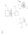
- FIG. 1 shows a vehicle 1 according to an embodiment of the present invention, which in the present case is a bicycle.
- the vehicle 1 comprises a frame 2 and a pedal crank drive 3, one on the Frame 2 held bottom bracket 4 and two attached to the bottom bracket 4 pedal arms 5 and 6, wherein the bottom bracket 4 defines an externally accessible cylindrical cavity 4 a, which extends through the bottom bracket 4 therethrough.
- the vehicle 1 comprises a power supply device 7 and a locating unit 8 connected to it, which are arranged within the hollow space 4a of the bottom bracket 4 and form part of a bicycle anti-theft detection system.
- Other components of the bicycle anti-theft location system in the present case are a computer 10 connected to a database 9 and at least one terminal of a user, for example in the form of a smartphone 11 and / or tablet PC 12.
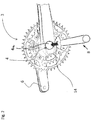
- the locating unit 8 comprises a tubular housing 13 whose outer dimensions are selected such that the housing 13 can be inserted into the cavity 4a of the bottom bracket 4, as shown in FIG FIG. 2 is indicated schematically by the arrow 14.
- the power supply device 7 Within the housing 13, the power supply device 7, a GPS and GSM device 15 electrically connected to the power supply device 7 with optional additional Bluetooth transmission technology and an antenna 16 electrically connected to the GPS and GSM device 15 are arranged.
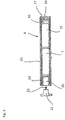
- the free ends of the housing 13 are closed with caps 17 and 18, which in the present case are firmly connected to the housing 13, in the present case adhesively bonded in order to protect the components arranged within the housing 13 from undesired access by third parties. In principle, however, the caps 17 and 18 can also be held detachably on the housing 13.
- the cap 17, which is disposed adjacent to the antenna 16, is provided with a through-hole 19 which may be filled with a non-metallic material, for example plastic or rubber.
- the passage opening 19 is intended to improve the reception of the antenna 16.
- In the cap 18 is an externally accessible and electrically connected to the power supply device. 7 connected charging cable socket 20 integrated in the form of a USB connector.
- the charging cable socket 20 can be closed from the outside with a plug made of rubber plug 21, which can be detachably inserted into the charging cable socket 20 in the direction of arrow 22 and the charging cable socket 20 dustproof and waterproof in the inserted state.
- the locating unit 8 and the bottom bracket 4 are connected to each other in such a way that the locating unit 8 can not be detached from the bottom bracket 4 nondestructively.
- the housing 13 is glued to the bottom bracket 4.
- the housing 13 of the locating unit 8 and the bottom bracket 4 but also pressed together, welded, soldered or mechanically inseparable connected to each other.
- the housing 13 of the locating unit 8 for example, be connected to the bottom bracket 4 via a destroyed thread.
- latching connections are conceivable, which develop their effect as soon as the housing 13 is properly inserted into the cavity 4a of the bottom bracket 4, such as snap connections or the like.
- the GPS and GSM device 15 receives GPS signals via the antenna 16 which are transmitted, for example, from various satellites. Based on these signals, the GPS and GSM device 15 can generate current position data of the locating unit 8 and thus of the vehicle 1. This position data sends the provided with a SIM card GPS and GSM device 15 via the antenna 16 to the computer 10, in this case via a mobile network, the received data to the smartphone 11 and / or to the tablet PC 12 of a user forwards. This is thus able to query the current location of his vehicle 1, if this has been stolen, for example.
- the communication between the locating unit 8, the computer 10 and the terminal of the user can be carried out continuously, at regular intervals, upon the occurrence of certain events or on request of the user. In principle, it is also possible to dispense with the computer 10, so that the communication takes place directly between the locating unit 8 and the terminal of the user.
- the locating unit 8 can be designed such that it can be activated and deactivated by the user.
- the activation or deactivation can take place, for example, via an inductive key chip or via Bluetooth via the user's terminal.
- the locating unit 8 can have a motion sensor which, as soon as it detects a movement, generates a signal which is transmitted in the form of a warning signal to the user's terminal. In this case, the user is informed immediately about an unplanned movement of the vehicle 1.
- the user can release the plug 21 from the outside and insert a charging cable into the charging cable socket 20, which is connected to an external power source.
- a charging cable can also be made inductively, to name just one example.
- the energy supply device 7 may, even if this is not shown here, be provided with a light that indicates the current charging status.
Landscapes
- Engineering & Computer Science (AREA)
- Radar, Positioning & Navigation (AREA)
- Remote Sensing (AREA)
- Mechanical Engineering (AREA)
- Computer Networks & Wireless Communication (AREA)
- Physics & Mathematics (AREA)
- General Physics & Mathematics (AREA)
- Signal Processing (AREA)
- Burglar Alarm Systems (AREA)
- Battery Mounting, Suspending (AREA)
Description
Die vorliegende Erfindung betrifft ein Fahrzeug, insbesondere Fahrrad, mit einem Rahmen, einem Tretkurbelantrieb, der ein an dem Rahmen gelagertes Tretlager und zwei an dem Tretlager befestigte Tretkurbelarme aufweist, einer Energieversorgungseinrichtung und einer mit dieser verbundenen Ortungseinheit, die einen Bestandteil eines Fahrrad-Diebstahlschutz-Ortungssystems bildet.The present invention relates to a vehicle, in particular a bicycle, comprising a frame, a pedal drive which has a bottom bracket mounted on the frame and two pedal arms attached to the bottom bracket, a power supply unit and a locating unit connected thereto which form part of a bicycle anti-theft device. Locating system forms.
Es sind bereits verschiede Ausgestaltungen von mit einer Ortungseinheit versehenen Fahrrädern bekannt. Die Ortungseinheit ist an eine Energieversorgungseinrichtung angeschlossen, welche die erforderliche Energie zum Betreiben der Ortungseinrichtung bereitstellt. Die Ortungseinheit weist normalerweise eine GPS- und GSM-Einrichtung auf, über welche die Positionsdaten des Fahrrads ermittelt und an einen zentralen Rechner eines Fahrrad-Diebstahlschutz-Ortungssystems gesendet werden können. Im Falle eines Diebstahls können dann die aktuellen Positionsdaten des Fahrrads abgerufen werden, um dieses ausfindig zu machen.There are already various embodiments of provided with a tracking unit bicycles known. The locating unit is connected to a power supply device, which provides the required energy for operating the locating device. The locating unit usually has a GPS and GSM device, via which the position data of the bicycle can be determined and sent to a central computer of a bicycle anti-theft positioning system. In the event of theft, then the current position data of the bicycle can be retrieved to locate this.
So offenbart beispielsweise die
Die
Die
Weitere Fahrrad-Diebstahlschutz-Systeme sind in den Druckschriften
Ausgehend von diesem Stand der Technik ist es eine Aufgabe der vorliegenden Erfindung, ein Fahrzeug der eingangs genannten Art mit alternativem Aufbau zu schaffen, der die zuvor beschriebenen Probleme zumindest teilweise behebt.Based on this prior art, it is an object of the present invention to provide a vehicle of the type mentioned above with an alternative structure, which at least partially solves the problems described above.
Zur Lösung dieser Aufgabe schafft die vorliegende Erfindung ein Fahrzeug nach Anspruch 1. Die erfindungsgemäße Anordnung der Ortungseinheit innerhalb des hohl ausgebildeten Tretlagers ist dahingehend von Vorteil, dass sich die Ortungseinheit sowohl bei der Herstellung des Fahrzeugs als auch nachträglich montieren lässt. Auch ist die Ortungseinheit von außen nicht sichtbar, so dass potentielle Diebe auf diese nicht aufmerksam werden. Zudem handelt es sich bei dem Tretlager um ein schwer demontierbares Bauteil des Fahrzeugs, weshalb sich die Ortungseinheit nur mit geeignetem Werkzeug und hohem Zeitaufwand zusammen mit dem Tretlager entfernen lässt.To achieve this object, the present invention provides a vehicle according to
Bevorzugt ist auch die Energieversorgungseinrichtung innerhalb des Hohlraums angeordnet, wodurch sich ein kompakter und einfacher Aufbau ergibt. Die Energieversorgungseinrichtung und die Ortungseinheit können dabei integral ausgebildet, beispielsweise in einem gemeinsamen Gehäuse angeordnet sein.Preferably, the power supply device is disposed within the cavity, resulting in a compact and simple construction. The power supply device and the locating unit can thereby integrally formed, for example, be arranged in a common housing.
Erfindungsgemäß sind die Ortungseinheit und das Tretlager derart miteinander verbunden, dass sich die Ortungseinheit nicht zerstörungsfrei von dem Tretlager lösen lässt. Entsprechend kann die Ortungseinheit nicht aus dem Tretlager entnommen werden.According to the locating unit and the bottom bracket are connected to each other such that the locating unit can not be solved without destroying the bottom bracket. Accordingly, the locating unit can not be removed from the bottom bracket.
Bevorzugt sind die Ortungseinheit und das Tretlager miteinander verpresst und/oder verschweißt und/oder verlötet und/oder verklebt und/oder mechanisch über ein zerstörtes Gewinde und/oder eine Rastverbindung aneinander befestigt, um nur einige Beispiele zu nennen.Preferably, the locating unit and the bottom bracket are pressed together and / or welded and / or soldered and / or glued and / or mechanically fastened to one another via a destroyed thread and / or a latching connection, to name just a few examples.
Die Energieversorgungseinrichtung ist vorteilhaft in Form eines Akkumulators vorgesehen. Entsprechend kann die Energieversorgungseinrichtung aufgeladen werden.The energy supply device is advantageously provided in the form of a rechargeable battery. Accordingly, the power supply device can be charged.
Die Energieversorgungseinrichtung ist bevorzugt derart ausgebildet, dass sie induktiv aufladbar ist. Alternativ oder zusätzlich kann die Energieversorgungseinrichtung eine oder mehrere Ladekabelsteckerbuchsen aufweisen, die derart angeordnet ist, dass sie von außen zugänglich ist. Entsprechend lässt sich die Energieversorgungseinrichtung problemlos von außen aufladen.The energy supply device is preferably designed such that it can be inductively charged. Alternatively or additionally, the power supply device may have one or more charging cable sockets, which is arranged such that it is accessible from the outside. Accordingly, the power supply device can be easily charged from the outside.
Gemäß einer Ausgestaltung der vorliegenden Erfindung weist die Ortungseinheit ein Gehäuse auf, das die Außenseite der Ortungseinheit definiert.According to one embodiment of the present invention, the locating unit has a housing which defines the outside of the locating unit.
Dies erleichtert die Handhabung und den Einbau der Ortungseinheit, so dass sich diese auch von einem Endnutzer installieren lässt. Alternativ kann das Gehäuse aber auch durch das Tretlager definiert werden.This facilitates the handling and installation of the locating unit so that it can also be installed by an end user. Alternatively, the housing can also be defined by the bottom bracket.
Bevorzugt ist das Gehäuse endseitig mit zumindest einer Kappe verschlossen.Preferably, the housing is closed at the end with at least one cap.
Die zumindest eine Kappe kann abnehmbar ausgebildet sein, um beispielsweise den Zugang zu der Ladekabelsteckerbuchse freizugeben, wenn eine solche vorgesehen ist.The at least one cap may be designed to be removable, for example, to enable access to the charging cable, if such is provided.
Alternativ kann die zumindest eine Kappe aber auch derart befestigt sein, dass sie sich nicht zerstörungsfrei von dem Gehäuse lösen lässt. Ist in diesem Fall eine Ladekabelsteckerbuchse vorhanden, so muss diese von außen durch die Kappe hindurch zugänglich sein.Alternatively, however, the at least one cap can also be fastened in such a way that it can not be detached from the housing in a nondestructive manner. If a charging cable socket is present in this case, it must be accessible from the outside through the cap.
Gemäß einer Ausgestaltung der vorliegenden Erfindung ist eine Antenne der Ortungseinheit unmittelbar benachbart zu der zumindest einen Kappe angeordnet oder in die Kappe integriert, um ein ordnungsgemäßes Senden und Empfangen von Signalen zu gewährleisten. Die Kappe kann zusätzlich mit einer Durchgangsöffnung versehen sein, um den Signalaustausch weiter zu verbessern.According to one embodiment of the present invention, an antenna of the locating unit is disposed immediately adjacent to the at least one cap or integrated in the cap to ensure proper transmission and reception of signals. The cap may additionally be provided with a passage opening in order to further improve the signal exchange.
Zur Lösung der eingangs genannten Aufgabe schafft die vorliegende Erfindung ferner ein Tretlager nach Anspruch 10.To achieve the object mentioned, the present invention further provides a bottom bracket according to
Bevorzugt ist in das Tretlager ferner eine mit der Ortungseinheit verbundene Energieversorgungseinrichtung angeordnet, die integral mit der Ortungseinheit ausgebildet, beispielsweise in einem gemeinsamen Gehäuse angeordnet sein kann.In addition, a power supply device connected to the locating unit is preferably arranged in the bottom bracket, which may be formed integrally with the locating unit, for example arranged in a common housing.
Weitere Merkmale und Vorteile der vorliegenden Erfindung werden anhand der nachfolgenden Beschreibung eines Fahrzeugs gemäß einer Ausführungsform der vorliegenden Erfindung unter Bezugnahme auf die beiliegende Zeichnung deutlich. Darin ist
Figur 1- eine schematische Ansicht eines Fahrrad-Diebstahlschutz-Ortungssystems gemäß einer Ausführungsform der vorliegenden Erfindung, das von einer an einem Fahrrad angeordneten Ortungseinheit erfasste Positionsdaten empfängt und an ein Endgerät eines Nutzers weiterleitet;
Figur 2- eine schematische perspektivische Ansicht eines Tretkurbelantriebs des in
Figur 1Figur 1 Figur 3- eine schematische Schnittansicht der in
Figur 2
- FIG. 1
- a schematic view of a bicycle anti-theft detection system according to an embodiment of the present invention, which receives from a positioning unit arranged on a bicycle and passes on to a terminal of a user;
- FIG. 2
- a schematic perspective view of a pedal drive of the in
FIG. 1 and a locating unit according to an embodiment of the present invention, which forms part of the inFIG. 1 illustrated bicycle anti-theft detection system, and - FIG. 3
- a schematic sectional view of in
FIG. 2 shown locating unit.
Die Ortungseinheit 8 umfasst ein rohrförmiges Gehäuse 13, dessen Außenabmessungen derart gewählt sind, dass das Gehäuse 13 in dem Hohlraum 4a des Tretlagers 4 eingesetzt werden kann, wie es in
Die Ortungseinheit 8 und das Tretlager 4 sind derart miteinander verbunden, dass sich die Ortungseinheit 8 nicht zerstörungsfrei von dem Tretlager 4 lösen lässt. Vorliegend ist hierzu das Gehäuse 13 mit dem Tretlager 4 verklebt. Alternativ können das Gehäuse 13 der Ortungseinheit 8 und das Tretlager 4 aber auch miteinander verpresst, verschweißt, verlötet oder auf mechanische Weise untrennbar miteinander verbunden sein. So kann das Gehäuse 13 der Ortungseinheit 8 beispielsweise mit dem Tretlager 4 über ein zerstörtes Gewinde verbunden sein. Alternativ sind auch Rastverbindungen denkbar, die ihre Wirkung entfalten, sobald das Gehäuse 13 ordnungsgemäß in den Hohlraum 4a des Tretlagers 4 eingesetzt ist, wie beispielsweise Schnappverbindungen oder dergleichen.The locating
Während des Betriebs des Fahrrad-Diebstahlschutz-Ortungssystems empfängt die GPS- und GSM-Einrichtung 15 über die Antenne 16 GPS-Signale, die beispielsweise von verschiedenen Satelliten ausgesendet werden. Anhand dieser Signale kann die GPS- und GSM-Einrichtung 15 aktuelle Positionsdaten der Ortungseinheit 8 und damit des Fahrzeugs 1 generieren. Diese Positionsdaten sendet die mit einer SIM-Karte versehene GPS- und GSM-Einrichtung 15 über die Antenne 16 an den Rechner 10, vorliegend über ein Mobilfunknetz, der die empfangenen Daten an das Smartphone 11 und/oder an den Tablet-PC 12 eines Nutzers weiterleitet. Dieser ist damit in der Lage, den aktuellen Standort seines Fahrzeugs 1 abzufragen, sollte dieses beispielsweise gestohlen worden sein. Die Kommunikation zwischen der Ortungseinheit 8, dem Rechner 10 und dem Endgerät des Nutzers kann kontinuierlich, in regelmäßigen zeitlichen Abständen, bei Eintreten bestimmter Ereignisse oder auf Anfrage des Nutzers erfolgen. Grundsätzlich ist es auch möglich, auf den Rechner 10 zu verzichten, so dass die Kommunikation direkt zwischen der Ortungseinheit 8 und dem Endgerät des Benutzers erfolgt.During operation of the bicycle theft deterrent location system, the GPS and
Die Ortungseinheit 8 kann derart ausgebildet sein, dass sie von dem Benutzer aktiviert und deaktiviert werden kann. Die Aktivierung bzw. Deaktivierung kann beispielsweise über einen induktiven Schlüssel-Chip oder per Bluetooth über das Endgerät des Benutzers erfolgen.The locating
Ferner kann die Ortungseinheit 8 über einen Bewegungssensor verfügen, der, sobald er eine Bewegung detektiert, ein Signal generiert, das in Form eines Warnsignals an das Endgerät des Benutzers übermittelt wird. In diesem Fall wird der Benutzer unmittelbar über eine ungeplante Bewegung des Fahrzeugs 1 unterrichtet.Furthermore, the locating
Zum Aufladen der Energieversorgungseinrichtung 7 kann der Nutzer den Stöpsel 21 von außen lösen und ein Ladekabel in die Ladekabelsteckerbuchse 20 einstecken, das mit einer externen Energiequelle verbunden ist. An dieser Stelle sei darauf hingewiesen, dass anstelle eines Ladekabels grundsätzlich auch auf eine andere Ladetechniken zurückgegriffen werden kann. So kann das Aufladen der Energieversorgungseinrichtung 7 auch induktiv erfolgen, um nur ein Beispiel zu nennen. Ebenso ist es grundsätzlich möglich, die Energieversorgungseinrichtung 7 mit einer nicht aufladbaren Energiequelle zu versehen, auch wenn eine solche Ausgestaltung nicht bevorzugt wird. Die Energieversorgungseinrichtung 7 kann, auch wenn dies vorliegend nicht dargestellt ist, mit einer Leuchte versehen sein, die den aktuellen Ladestatus anzeigt.To charge the
Claims (11)
- Vehicle (1), in particular a bicycle, having a frame (2), a pedal crank drive (3) which has a bottom bracket (4) which is held on the frame (2) and two pedal crank arms (5, 6) which are fastened to the bottom bracket (4), a power supply device (7) and a locating unit (8) which is connected to the power supply device (7) and forms part of a bicycle anti-theft locating system, characterized in that the bottom bracket (4) has an externally accessible cavity (4a) extending through the bottom bracket (4), in that the locating unit (8) has a tubular housing (13), and in that at least the locating unit (8) is arranged inside the cavity (4a), the locating unit (8) and the bottom bracket (4) being connected to one another in such a way that the locating unit (8) cannot be detached from the bottom bracket (4) in a non-destructive manner.
- Vehicle (1) according to claim 1, characterized in that the power supply device (7) is arranged inside the cavity (4a), wherein the power supply device (7) and the locating unit (4) can be integrally formed.
- Vehicle (1) in accordance with one of the preceding claims, characterized in that the locating unit (8) and the bottom bracket (4) are pressed and/or welded and/or brazed and/or glued and/or mechanically fastened to one another via a destroyed thread and/or a latching connection.
- Vehicle (1) according to one of the preceding claims, characterized in that the power supply device (7) is provided in the form of an accumulator.
- Vehicle (1) according to claim 4, characterized in that the power supply device (7) is designed in such a way that it can be charged inductively, and/or in that the power supply device (7) has one or more charging cable plug sockets (20) which are arranged in such a way that they are accessible from the outside.
- Vehicle (1) according to one of the preceding claims, characterized in that the locating unit (8) comprises a housing (13) defining the outside of the locating unit (8).
- Vehicle (1) according to claim 6, characterized in that the housing (13) of the locating unit (8) is closed at the end with at least one cap (17, 18).
- Vehicle (1) according to claim 7, characterized in that the at least one cap (17, 18) is fastened in such a way that it cannot be detached from the housing (13) in a non-destructive manner.
- Vehicle (1) according to claim 7 or 8, characterized in that an antenna (16) of the locating unit (8) is arranged inside the housing (13) and immediately adjacent to the at least one cap (17, 18) or integrated into the cap.
- Bottom bracket (4), characterized in that it has a cylindrical cavity (4a) which is accessible from the outside and extends through the bottom bracket (4) and in which a locating unit (8) with a tubular housing (13) is arranged, the locating unit (8) and the bottom bracket (4) being connected to one another in such a way that the locating unit (8) cannot be detached from the bottom bracket (4) in a non-destructive manner.
- Bottom bracket (4) according to claim 10, characterized in that an energy supply device (7) connected to the locating unit (8) is arranged in the cavity (4a).
Applications Claiming Priority (1)
| Application Number | Priority Date | Filing Date | Title |
|---|---|---|---|
| DE102015108930.0A DE102015108930A1 (en) | 2015-06-05 | 2015-06-05 | Vehicle with pedal drive and locating unit |
Publications (2)
| Publication Number | Publication Date |
|---|---|
| EP3100936A1 EP3100936A1 (en) | 2016-12-07 |
| EP3100936B1 true EP3100936B1 (en) | 2019-06-19 |
Family
ID=56108536
Family Applications (1)
| Application Number | Title | Priority Date | Filing Date |
|---|---|---|---|
| EP16172720.1A Active EP3100936B1 (en) | 2015-06-05 | 2016-06-02 | Vehicle with a tread crank drive and locating unit |
Country Status (2)
| Country | Link |
|---|---|
| EP (1) | EP3100936B1 (en) |
| DE (1) | DE102015108930A1 (en) |
Families Citing this family (1)
| Publication number | Priority date | Publication date | Assignee | Title |
|---|---|---|---|---|
| IT201900003833A1 (en) * | 2019-03-15 | 2020-09-15 | Telamone S R L | Method for locating bicycles, anti-theft device and system for locating bicycles. |
Citations (2)
| Publication number | Priority date | Publication date | Assignee | Title |
|---|---|---|---|---|
| DE102009033475A1 (en) * | 2009-07-10 | 2011-01-13 | Holger Redtel | Securing device and method for preventing unauthorized startup of a vehicle |
| EP3018044A1 (en) * | 2014-11-05 | 2016-05-11 | Fraunhofer-Gesellschaft zur Förderung der angewandten Forschung e.V. | Bottom bracket device, bicycle with at least one bottom bracket device and system for locating at least one bicycle |
Family Cites Families (4)
| Publication number | Priority date | Publication date | Assignee | Title |
|---|---|---|---|---|
| DE102005001209A1 (en) | 2005-01-11 | 2006-07-20 | Hans-Peter Leicht | Stolen bicycle positioning, detecting and locking device, has global positioning system/Galileo receiver chip which includes antenna and power supply, where chip is built within inaccessible place in hollow frame of bicycle |
| DE202005007448U1 (en) * | 2005-05-13 | 2005-10-13 | Hofbauer, Thomas | Bicycle security device built into bicycle frame contains batteries, antennae, and positioning and signalling unit enabling bike to be located if stolen |
| DE202008009614U1 (en) | 2008-07-17 | 2008-10-30 | Seetrack Gmbh | In a bicycle seat post integrated GPS / GSM tracking device as anti-theft device |
| GB2484273A (en) | 2010-10-04 | 2012-04-11 | Harley Clark | Bicycle GPS tracking system |
-
2015
- 2015-06-05 DE DE102015108930.0A patent/DE102015108930A1/en not_active Withdrawn
-
2016
- 2016-06-02 EP EP16172720.1A patent/EP3100936B1/en active Active
Patent Citations (2)
| Publication number | Priority date | Publication date | Assignee | Title |
|---|---|---|---|---|
| DE102009033475A1 (en) * | 2009-07-10 | 2011-01-13 | Holger Redtel | Securing device and method for preventing unauthorized startup of a vehicle |
| EP3018044A1 (en) * | 2014-11-05 | 2016-05-11 | Fraunhofer-Gesellschaft zur Förderung der angewandten Forschung e.V. | Bottom bracket device, bicycle with at least one bottom bracket device and system for locating at least one bicycle |
Also Published As
| Publication number | Publication date |
|---|---|
| DE102015108930A1 (en) | 2016-12-08 |
| EP3100936A1 (en) | 2016-12-07 |
Similar Documents
| Publication | Publication Date | Title |
|---|---|---|
| EP3159254A1 (en) | Vehicle, especially a bicycle | |
| DE102008043632A1 (en) | Antenna device and motor vehicle with an antenna device | |
| DE3234583A1 (en) | ANTI-THEFT SECURITY | |
| WO2004033279A2 (en) | Bicycle lock | |
| DE102014213392A1 (en) | Retrofit driver assistance system for a two-wheeler | |
| EP3567192A1 (en) | Mobile lock | |
| DE102011107880A1 (en) | Installation device for installing global positioning system chip in seat post of bicycle to detect position and movements of bicycle, has seat post whose lower end forms antenna, and locating module activated by movement sensor | |
| EP3100936B1 (en) | Vehicle with a tread crank drive and locating unit | |
| WO2006027133A1 (en) | Display device for displaying a theft attempt and method for operating said device | |
| DE202011002447U1 (en) | Safety system for vehicles, especially for two-wheelers | |
| DE202019104685U1 (en) | Luggage rack and rear light unit for a two-wheeler | |
| CH702459B1 (en) | Anti-theft device of two-wheelers. | |
| EP3587227A2 (en) | Frame lock | |
| DE202011103444U1 (en) | Installation of a GPS and / or GSM locating module in a bicycle seat post | |
| DE102011103250A1 (en) | Device for monitoring installation position of sensor in sensor holder arranged on vehicle, has electrical contact whose preset breaking point medium is secured, so that electric current flow through preset breaking section is realized | |
| DE102018126356A1 (en) | frame lock | |
| DE202006014271U1 (en) | Solar-powered cycle lock has cable wound round drum rotatably mounted in housing with spiral spring between housing and drum and with solar cells and voltage source | |
| DE202014001086U1 (en) | Data reporting system integrated in a bicycle pedals | |
| DE102020213084A1 (en) | System and method for increasing the safety of road users without their own motor vehicle | |
| DE102019114830A1 (en) | Authentication system and backup procedures | |
| EP3739154B1 (en) | Locking system | |
| DE202018006482U1 (en) | Housing sleeve for a two-wheeler | |
| DE202018006857U1 (en) | Shaft element of a wheel fastening device and wheel fastening device | |
| DE102018203946A1 (en) | OBD dongle and method for determining unauthorized access to a means of transportation or to its periphery | |
| EP3621046B1 (en) | Alarm device for lorries |
Legal Events
| Date | Code | Title | Description |
|---|---|---|---|
| PUAI | Public reference made under article 153(3) epc to a published international application that has entered the european phase |
Free format text: ORIGINAL CODE: 0009012 |
|
| STAA | Information on the status of an ep patent application or granted ep patent |
Free format text: STATUS: THE APPLICATION HAS BEEN PUBLISHED |
|
| AK | Designated contracting states |
Kind code of ref document: A1 Designated state(s): AL AT BE BG CH CY CZ DE DK EE ES FI FR GB GR HR HU IE IS IT LI LT LU LV MC MK MT NL NO PL PT RO RS SE SI SK SM TR |
|
| AX | Request for extension of the european patent |
Extension state: BA ME |
|
| RAP1 | Party data changed (applicant data changed or rights of an application transferred) |
Owner name: GPS-NO.COM GMBH |
|
| STAA | Information on the status of an ep patent application or granted ep patent |
Free format text: STATUS: REQUEST FOR EXAMINATION WAS MADE |
|
| 17P | Request for examination filed |
Effective date: 20170601 |
|
| RBV | Designated contracting states (corrected) |
Designated state(s): AL AT BE BG CH CY CZ DE DK EE ES FI FR GB GR HR HU IE IS IT LI LT LU LV MC MK MT NL NO PL PT RO RS SE SI SK SM TR |
|
| STAA | Information on the status of an ep patent application or granted ep patent |
Free format text: STATUS: EXAMINATION IS IN PROGRESS |
|
| 17Q | First examination report despatched |
Effective date: 20171019 |
|
| GRAP | Despatch of communication of intention to grant a patent |
Free format text: ORIGINAL CODE: EPIDOSNIGR1 |
|
| STAA | Information on the status of an ep patent application or granted ep patent |
Free format text: STATUS: GRANT OF PATENT IS INTENDED |
|
| INTG | Intention to grant announced |
Effective date: 20190222 |
|
| GRAS | Grant fee paid |
Free format text: ORIGINAL CODE: EPIDOSNIGR3 |
|
| GRAA | (expected) grant |
Free format text: ORIGINAL CODE: 0009210 |
|
| STAA | Information on the status of an ep patent application or granted ep patent |
Free format text: STATUS: THE PATENT HAS BEEN GRANTED |
|
| AK | Designated contracting states |
Kind code of ref document: B1 Designated state(s): AL AT BE BG CH CY CZ DE DK EE ES FI FR GB GR HR HU IE IS IT LI LT LU LV MC MK MT NL NO PL PT RO RS SE SI SK SM TR |
|
| REG | Reference to a national code |
Ref country code: GB Ref legal event code: FG4D Free format text: NOT ENGLISH |
|
| REG | Reference to a national code |
Ref country code: CH Ref legal event code: EP |
|
| REG | Reference to a national code |
Ref country code: IE Ref legal event code: FG4D Free format text: LANGUAGE OF EP DOCUMENT: GERMAN |
|
| REG | Reference to a national code |
Ref country code: AT Ref legal event code: REF Ref document number: 1145150 Country of ref document: AT Kind code of ref document: T Effective date: 20190715 |
|
| REG | Reference to a national code |
Ref country code: DE Ref legal event code: R096 Ref document number: 502016005112 Country of ref document: DE |
|
| REG | Reference to a national code |
Ref country code: NL Ref legal event code: MP Effective date: 20190619 |
|
| PG25 | Lapsed in a contracting state [announced via postgrant information from national office to epo] |
Ref country code: NO Free format text: LAPSE BECAUSE OF FAILURE TO SUBMIT A TRANSLATION OF THE DESCRIPTION OR TO PAY THE FEE WITHIN THE PRESCRIBED TIME-LIMIT Effective date: 20190919 Ref country code: FI Free format text: LAPSE BECAUSE OF FAILURE TO SUBMIT A TRANSLATION OF THE DESCRIPTION OR TO PAY THE FEE WITHIN THE PRESCRIBED TIME-LIMIT Effective date: 20190619 Ref country code: AL Free format text: LAPSE BECAUSE OF FAILURE TO SUBMIT A TRANSLATION OF THE DESCRIPTION OR TO PAY THE FEE WITHIN THE PRESCRIBED TIME-LIMIT Effective date: 20190619 Ref country code: SE Free format text: LAPSE BECAUSE OF FAILURE TO SUBMIT A TRANSLATION OF THE DESCRIPTION OR TO PAY THE FEE WITHIN THE PRESCRIBED TIME-LIMIT Effective date: 20190619 Ref country code: HR Free format text: LAPSE BECAUSE OF FAILURE TO SUBMIT A TRANSLATION OF THE DESCRIPTION OR TO PAY THE FEE WITHIN THE PRESCRIBED TIME-LIMIT Effective date: 20190619 Ref country code: LT Free format text: LAPSE BECAUSE OF FAILURE TO SUBMIT A TRANSLATION OF THE DESCRIPTION OR TO PAY THE FEE WITHIN THE PRESCRIBED TIME-LIMIT Effective date: 20190619 |
|
| REG | Reference to a national code |
Ref country code: LT Ref legal event code: MG4D |
|
| PG25 | Lapsed in a contracting state [announced via postgrant information from national office to epo] |
Ref country code: RS Free format text: LAPSE BECAUSE OF FAILURE TO SUBMIT A TRANSLATION OF THE DESCRIPTION OR TO PAY THE FEE WITHIN THE PRESCRIBED TIME-LIMIT Effective date: 20190619 Ref country code: GR Free format text: LAPSE BECAUSE OF FAILURE TO SUBMIT A TRANSLATION OF THE DESCRIPTION OR TO PAY THE FEE WITHIN THE PRESCRIBED TIME-LIMIT Effective date: 20190920 Ref country code: BG Free format text: LAPSE BECAUSE OF FAILURE TO SUBMIT A TRANSLATION OF THE DESCRIPTION OR TO PAY THE FEE WITHIN THE PRESCRIBED TIME-LIMIT Effective date: 20190919 Ref country code: LV Free format text: LAPSE BECAUSE OF FAILURE TO SUBMIT A TRANSLATION OF THE DESCRIPTION OR TO PAY THE FEE WITHIN THE PRESCRIBED TIME-LIMIT Effective date: 20190619 |
|
| PG25 | Lapsed in a contracting state [announced via postgrant information from national office to epo] |
Ref country code: CZ Free format text: LAPSE BECAUSE OF FAILURE TO SUBMIT A TRANSLATION OF THE DESCRIPTION OR TO PAY THE FEE WITHIN THE PRESCRIBED TIME-LIMIT Effective date: 20190619 Ref country code: RO Free format text: LAPSE BECAUSE OF FAILURE TO SUBMIT A TRANSLATION OF THE DESCRIPTION OR TO PAY THE FEE WITHIN THE PRESCRIBED TIME-LIMIT Effective date: 20190619 Ref country code: SK Free format text: LAPSE BECAUSE OF FAILURE TO SUBMIT A TRANSLATION OF THE DESCRIPTION OR TO PAY THE FEE WITHIN THE PRESCRIBED TIME-LIMIT Effective date: 20190619 Ref country code: PT Free format text: LAPSE BECAUSE OF FAILURE TO SUBMIT A TRANSLATION OF THE DESCRIPTION OR TO PAY THE FEE WITHIN THE PRESCRIBED TIME-LIMIT Effective date: 20191021 Ref country code: EE Free format text: LAPSE BECAUSE OF FAILURE TO SUBMIT A TRANSLATION OF THE DESCRIPTION OR TO PAY THE FEE WITHIN THE PRESCRIBED TIME-LIMIT Effective date: 20190619 Ref country code: NL Free format text: LAPSE BECAUSE OF FAILURE TO SUBMIT A TRANSLATION OF THE DESCRIPTION OR TO PAY THE FEE WITHIN THE PRESCRIBED TIME-LIMIT Effective date: 20190619 |
|
| PG25 | Lapsed in a contracting state [announced via postgrant information from national office to epo] |
Ref country code: IT Free format text: LAPSE BECAUSE OF FAILURE TO SUBMIT A TRANSLATION OF THE DESCRIPTION OR TO PAY THE FEE WITHIN THE PRESCRIBED TIME-LIMIT Effective date: 20190619 Ref country code: IS Free format text: LAPSE BECAUSE OF FAILURE TO SUBMIT A TRANSLATION OF THE DESCRIPTION OR TO PAY THE FEE WITHIN THE PRESCRIBED TIME-LIMIT Effective date: 20191019 Ref country code: SM Free format text: LAPSE BECAUSE OF FAILURE TO SUBMIT A TRANSLATION OF THE DESCRIPTION OR TO PAY THE FEE WITHIN THE PRESCRIBED TIME-LIMIT Effective date: 20190619 Ref country code: ES Free format text: LAPSE BECAUSE OF FAILURE TO SUBMIT A TRANSLATION OF THE DESCRIPTION OR TO PAY THE FEE WITHIN THE PRESCRIBED TIME-LIMIT Effective date: 20190619 |
|
| PG25 | Lapsed in a contracting state [announced via postgrant information from national office to epo] |
Ref country code: TR Free format text: LAPSE BECAUSE OF FAILURE TO SUBMIT A TRANSLATION OF THE DESCRIPTION OR TO PAY THE FEE WITHIN THE PRESCRIBED TIME-LIMIT Effective date: 20190619 |
|
| PG25 | Lapsed in a contracting state [announced via postgrant information from national office to epo] |
Ref country code: PL Free format text: LAPSE BECAUSE OF FAILURE TO SUBMIT A TRANSLATION OF THE DESCRIPTION OR TO PAY THE FEE WITHIN THE PRESCRIBED TIME-LIMIT Effective date: 20190619 Ref country code: DK Free format text: LAPSE BECAUSE OF FAILURE TO SUBMIT A TRANSLATION OF THE DESCRIPTION OR TO PAY THE FEE WITHIN THE PRESCRIBED TIME-LIMIT Effective date: 20190619 |
|
| PG25 | Lapsed in a contracting state [announced via postgrant information from national office to epo] |
Ref country code: IS Free format text: LAPSE BECAUSE OF FAILURE TO SUBMIT A TRANSLATION OF THE DESCRIPTION OR TO PAY THE FEE WITHIN THE PRESCRIBED TIME-LIMIT Effective date: 20200224 |
|
| REG | Reference to a national code |
Ref country code: DE Ref legal event code: R097 Ref document number: 502016005112 Country of ref document: DE |
|
| PLBE | No opposition filed within time limit |
Free format text: ORIGINAL CODE: 0009261 |
|
| STAA | Information on the status of an ep patent application or granted ep patent |
Free format text: STATUS: NO OPPOSITION FILED WITHIN TIME LIMIT |
|
| PG2D | Information on lapse in contracting state deleted |
Ref country code: IS |
|
| 26N | No opposition filed |
Effective date: 20200603 |
|
| PG25 | Lapsed in a contracting state [announced via postgrant information from national office to epo] |
Ref country code: SI Free format text: LAPSE BECAUSE OF FAILURE TO SUBMIT A TRANSLATION OF THE DESCRIPTION OR TO PAY THE FEE WITHIN THE PRESCRIBED TIME-LIMIT Effective date: 20190619 |
|
| PG25 | Lapsed in a contracting state [announced via postgrant information from national office to epo] |
Ref country code: MC Free format text: LAPSE BECAUSE OF FAILURE TO SUBMIT A TRANSLATION OF THE DESCRIPTION OR TO PAY THE FEE WITHIN THE PRESCRIBED TIME-LIMIT Effective date: 20190619 |
|
| PG25 | Lapsed in a contracting state [announced via postgrant information from national office to epo] |
Ref country code: LU Free format text: LAPSE BECAUSE OF NON-PAYMENT OF DUE FEES Effective date: 20200602 |
|
| REG | Reference to a national code |
Ref country code: BE Ref legal event code: MM Effective date: 20200630 |
|
| PG25 | Lapsed in a contracting state [announced via postgrant information from national office to epo] |
Ref country code: IE Free format text: LAPSE BECAUSE OF NON-PAYMENT OF DUE FEES Effective date: 20200602 |
|
| PG25 | Lapsed in a contracting state [announced via postgrant information from national office to epo] |
Ref country code: BE Free format text: LAPSE BECAUSE OF NON-PAYMENT OF DUE FEES Effective date: 20200630 |
|
| REG | Reference to a national code |
Ref country code: DE Ref legal event code: R081 Ref document number: 502016005112 Country of ref document: DE Owner name: CODE-NO.COM GMBH, DE Free format text: FORMER OWNER: GPS-NO.COM GMBH, 60386 FRANKFURT, DE |
|
| REG | Reference to a national code |
Ref country code: LU Ref legal event code: PD Owner name: CODE-NO.COM GMBH; DE Free format text: FORMER OWNER: GPS-NO.COM GMBH Effective date: 20220201 Ref country code: LU Ref legal event code: NF |
|
| REG | Reference to a national code |
Ref country code: AT Ref legal event code: PC Ref document number: 1145150 Country of ref document: AT Kind code of ref document: T Owner name: CODE-NO.COM GMBH, DE Effective date: 20220310 |
|
| PG25 | Lapsed in a contracting state [announced via postgrant information from national office to epo] |
Ref country code: MT Free format text: LAPSE BECAUSE OF FAILURE TO SUBMIT A TRANSLATION OF THE DESCRIPTION OR TO PAY THE FEE WITHIN THE PRESCRIBED TIME-LIMIT Effective date: 20190619 Ref country code: LU Free format text: LAPSE BECAUSE OF NON-PAYMENT OF DUE FEES Effective date: 20200602 Ref country code: CY Free format text: LAPSE BECAUSE OF FAILURE TO SUBMIT A TRANSLATION OF THE DESCRIPTION OR TO PAY THE FEE WITHIN THE PRESCRIBED TIME-LIMIT Effective date: 20190619 |
|
| PGFP | Annual fee paid to national office [announced via postgrant information from national office to epo] |
Ref country code: LU Payment date: 20220211 Year of fee payment: 6 |
|
| PGRI | Patent reinstated in contracting state [announced from national office to epo] |
Ref country code: LU Effective date: 20220214 |
|
| PG25 | Lapsed in a contracting state [announced via postgrant information from national office to epo] |
Ref country code: MK Free format text: LAPSE BECAUSE OF FAILURE TO SUBMIT A TRANSLATION OF THE DESCRIPTION OR TO PAY THE FEE WITHIN THE PRESCRIBED TIME-LIMIT Effective date: 20190619 |
|
| PGFP | Annual fee paid to national office [announced via postgrant information from national office to epo] |
Ref country code: GB Payment date: 20220520 Year of fee payment: 7 Ref country code: FR Payment date: 20220520 Year of fee payment: 7 |
|
| PGFP | Annual fee paid to national office [announced via postgrant information from national office to epo] |
Ref country code: AT Payment date: 20220608 Year of fee payment: 7 |
|
| PGFP | Annual fee paid to national office [announced via postgrant information from national office to epo] |
Ref country code: CH Payment date: 20220629 Year of fee payment: 7 |
|
| PG25 | Lapsed in a contracting state [announced via postgrant information from national office to epo] |
Ref country code: LU Free format text: LAPSE BECAUSE OF NON-PAYMENT OF DUE FEES Effective date: 20220602 |
|
| PGFP | Annual fee paid to national office [announced via postgrant information from national office to epo] |
Ref country code: DE Payment date: 20230605 Year of fee payment: 8 |
|
| REG | Reference to a national code |
Ref country code: CH Ref legal event code: PL |
|
| REG | Reference to a national code |
Ref country code: AT Ref legal event code: MM01 Ref document number: 1145150 Country of ref document: AT Kind code of ref document: T Effective date: 20230602 |
|
| GBPC | Gb: european patent ceased through non-payment of renewal fee |
Effective date: 20230602 |
|
| PG25 | Lapsed in a contracting state [announced via postgrant information from national office to epo] |
Ref country code: AT Free format text: LAPSE BECAUSE OF NON-PAYMENT OF DUE FEES Effective date: 20230602 |
|
| PG25 | Lapsed in a contracting state [announced via postgrant information from national office to epo] |
Ref country code: AT Free format text: LAPSE BECAUSE OF NON-PAYMENT OF DUE FEES Effective date: 20230602 Ref country code: GB Free format text: LAPSE BECAUSE OF NON-PAYMENT OF DUE FEES Effective date: 20230602 Ref country code: CH Free format text: LAPSE BECAUSE OF NON-PAYMENT OF DUE FEES Effective date: 20230630 |