EP3097869A1 - Surgical device - Google Patents
Surgical device Download PDFInfo
- Publication number
- EP3097869A1 EP3097869A1 EP16178984.7A EP16178984A EP3097869A1 EP 3097869 A1 EP3097869 A1 EP 3097869A1 EP 16178984 A EP16178984 A EP 16178984A EP 3097869 A1 EP3097869 A1 EP 3097869A1
- Authority
- EP
- European Patent Office
- Prior art keywords
- jaw
- gear
- shaft
- surgical device
- relative
- Prior art date
- Legal status (The legal status is an assumption and is not a legal conclusion. Google has not performed a legal analysis and makes no representation as to the accuracy of the status listed.)
- Granted
Links
- 238000006073 displacement reaction Methods 0.000 claims abstract description 7
- 230000008878 coupling Effects 0.000 description 60
- 238000010168 coupling process Methods 0.000 description 60
- 238000005859 coupling reaction Methods 0.000 description 60
- 230000033001 locomotion Effects 0.000 description 31
- 238000000034 method Methods 0.000 description 22
- 230000006870 function Effects 0.000 description 19
- 230000007246 mechanism Effects 0.000 description 14
- 238000012546 transfer Methods 0.000 description 7
- 230000000295 complement effect Effects 0.000 description 6
- 238000004891 communication Methods 0.000 description 4
- 238000010304 firing Methods 0.000 description 3
- 230000002439 hemostatic effect Effects 0.000 description 3
- 230000003287 optical effect Effects 0.000 description 3
- 230000005355 Hall effect Effects 0.000 description 2
- 230000008901 benefit Effects 0.000 description 2
- 230000005540 biological transmission Effects 0.000 description 2
- 238000010586 diagram Methods 0.000 description 2
- 238000004519 manufacturing process Methods 0.000 description 2
- 230000013011 mating Effects 0.000 description 2
- 230000008569 process Effects 0.000 description 2
- 230000004044 response Effects 0.000 description 2
- 230000000717 retained effect Effects 0.000 description 2
- 238000007789 sealing Methods 0.000 description 2
- 208000032953 Device battery issue Diseases 0.000 description 1
- 210000001015 abdomen Anatomy 0.000 description 1
- 230000002547 anomalous effect Effects 0.000 description 1
- 230000008859 change Effects 0.000 description 1
- 239000011248 coating agent Substances 0.000 description 1
- 238000000576 coating method Methods 0.000 description 1
- 210000001072 colon Anatomy 0.000 description 1
- 238000013479 data entry Methods 0.000 description 1
- 230000007423 decrease Effects 0.000 description 1
- 238000001514 detection method Methods 0.000 description 1
- 239000013536 elastomeric material Substances 0.000 description 1
- 210000001035 gastrointestinal tract Anatomy 0.000 description 1
- 230000006872 improvement Effects 0.000 description 1
- 238000010348 incorporation Methods 0.000 description 1
- 208000015181 infectious disease Diseases 0.000 description 1
- 238000003780 insertion Methods 0.000 description 1
- 230000037431 insertion Effects 0.000 description 1
- 239000000463 material Substances 0.000 description 1
- 238000005259 measurement Methods 0.000 description 1
- 238000012986 modification Methods 0.000 description 1
- 230000004048 modification Effects 0.000 description 1
- 239000013307 optical fiber Substances 0.000 description 1
- 230000002085 persistent effect Effects 0.000 description 1
- 239000011295 pitch Substances 0.000 description 1
- 238000001356 surgical procedure Methods 0.000 description 1
- 230000000007 visual effect Effects 0.000 description 1
Images


Classifications
-
- A—HUMAN NECESSITIES
- A61—MEDICAL OR VETERINARY SCIENCE; HYGIENE
- A61B—DIAGNOSIS; SURGERY; IDENTIFICATION
- A61B17/00—Surgical instruments, devices or methods, e.g. tourniquets
- A61B17/068—Surgical staplers, e.g. containing multiple staples or clamps
-
- A—HUMAN NECESSITIES
- A61—MEDICAL OR VETERINARY SCIENCE; HYGIENE
- A61B—DIAGNOSIS; SURGERY; IDENTIFICATION
- A61B17/00—Surgical instruments, devices or methods, e.g. tourniquets
- A61B17/068—Surgical staplers, e.g. containing multiple staples or clamps
- A61B17/072—Surgical staplers, e.g. containing multiple staples or clamps for applying a row of staples in a single action, e.g. the staples being applied simultaneously
- A61B17/07207—Surgical staplers, e.g. containing multiple staples or clamps for applying a row of staples in a single action, e.g. the staples being applied simultaneously the staples being applied sequentially
-
- A—HUMAN NECESSITIES
- A61—MEDICAL OR VETERINARY SCIENCE; HYGIENE
- A61B—DIAGNOSIS; SURGERY; IDENTIFICATION
- A61B17/00—Surgical instruments, devices or methods, e.g. tourniquets
- A61B2017/00367—Details of actuation of instruments, e.g. relations between pushing buttons, or the like, and activation of the tool, working tip, or the like
- A61B2017/00398—Details of actuation of instruments, e.g. relations between pushing buttons, or the like, and activation of the tool, working tip, or the like using powered actuators, e.g. stepper motors, solenoids
-
- A—HUMAN NECESSITIES
- A61—MEDICAL OR VETERINARY SCIENCE; HYGIENE
- A61B—DIAGNOSIS; SURGERY; IDENTIFICATION
- A61B17/00—Surgical instruments, devices or methods, e.g. tourniquets
- A61B2017/00681—Aspects not otherwise provided for
- A61B2017/00734—Aspects not otherwise provided for battery operated
-
- A—HUMAN NECESSITIES
- A61—MEDICAL OR VETERINARY SCIENCE; HYGIENE
- A61B—DIAGNOSIS; SURGERY; IDENTIFICATION
- A61B17/00—Surgical instruments, devices or methods, e.g. tourniquets
- A61B17/068—Surgical staplers, e.g. containing multiple staples or clamps
- A61B17/072—Surgical staplers, e.g. containing multiple staples or clamps for applying a row of staples in a single action, e.g. the staples being applied simultaneously
- A61B2017/07214—Stapler heads
- A61B2017/07278—Stapler heads characterised by its sled or its staple holder
-
- A—HUMAN NECESSITIES
- A61—MEDICAL OR VETERINARY SCIENCE; HYGIENE
- A61B—DIAGNOSIS; SURGERY; IDENTIFICATION
- A61B17/00—Surgical instruments, devices or methods, e.g. tourniquets
- A61B17/068—Surgical staplers, e.g. containing multiple staples or clamps
- A61B17/072—Surgical staplers, e.g. containing multiple staples or clamps for applying a row of staples in a single action, e.g. the staples being applied simultaneously
- A61B2017/07214—Stapler heads
- A61B2017/07285—Stapler heads characterised by its cutter
-
- A—HUMAN NECESSITIES
- A61—MEDICAL OR VETERINARY SCIENCE; HYGIENE
- A61B—DIAGNOSIS; SURGERY; IDENTIFICATION
- A61B17/00—Surgical instruments, devices or methods, e.g. tourniquets
- A61B17/28—Surgical forceps
- A61B17/29—Forceps for use in minimally invasive surgery
- A61B2017/2926—Details of heads or jaws
- A61B2017/2927—Details of heads or jaws the angular position of the head being adjustable with respect to the shaft
- A61B2017/2929—Details of heads or jaws the angular position of the head being adjustable with respect to the shaft with a head rotatable about the longitudinal axis of the shaft
-
- A—HUMAN NECESSITIES
- A61—MEDICAL OR VETERINARY SCIENCE; HYGIENE
- A61B—DIAGNOSIS; SURGERY; IDENTIFICATION
- A61B17/00—Surgical instruments, devices or methods, e.g. tourniquets
- A61B17/28—Surgical forceps
- A61B17/29—Forceps for use in minimally invasive surgery
- A61B2017/2926—Details of heads or jaws
- A61B2017/2932—Transmission of forces to jaw members
- A61B2017/2943—Toothed members, e.g. rack and pinion
-
- A—HUMAN NECESSITIES
- A61—MEDICAL OR VETERINARY SCIENCE; HYGIENE
- A61B—DIAGNOSIS; SURGERY; IDENTIFICATION
- A61B17/00—Surgical instruments, devices or methods, e.g. tourniquets
- A61B17/32—Surgical cutting instruments
- A61B2017/320052—Guides for cutting instruments
Definitions
- FIG. 1 One type of surgical device is a linear clamping, cutting and stapling device. Such a device may be employed in a surgical procedure to resect a cancerous or anomalous tissue from a gastro-intestinal tract.
- a linear clamping, cutting and stapling instrument is shown in Figure 1 .
- the device includes a pistol grip-styled structure having an elongated shaft and distal portion.
- the distal portion includes a pair of scissors-styled gripping elements, which clamp the open ends of the colon closed.
- one of the two scissors-styled gripping elements such as the anvil portion, moves or pivots relative to the overall structure, whereas the other gripping element remains fixed relative to the overall structure.
- the actuation of this scissoring device (the pivoting of the anvil portion) is controlled by a grip trigger maintained in the handle.
- the method may also include the steps of moving the idler gear to a proximal position such that the idler gear is out of engagement with the recesses of the housing and rotating the idler gear relative to the housing.
- the surgical member may be moved within the second jaw.
- the surgical member includes at least one of a cutting element and a stapling element, and the step of moving the surgical member includes at least one of cutting and stapling a section of tissue.
- the second jaw 80 also includes a second driver 98.
- the second driver 98 may also extend through the shaft portion 11b of the surgical device 11 to a second drive socket 694.
- the second drive socket 694 is coupled to a second motor 100 by a second drive shaft 102.
- the second driver 98 when engaged by the second motor 100 via the second drive shaft 102, may operate to drive the cutting and stapling element 104 to cut and staple a section of tissue 52, in addition to performing other operations of the surgical device 11.
- the wedge 603 also includes a pair of sloped edges 603b that slideably engage respective top surfaces 607a of the staple pushers 607.
- the pair of sloped edges 603b of the wedge 603 is configured to slideably engage the respective top surfaces 607a of the staple pushers 607 in order to successively push the staple pushing fingers 607c of the staple pushers 607 into, and thus the staples 606 out of, the slots 604h in the staple tray 604.
- gear element 506 Since the gear element 506 is attached to the gear element 510 by the shaft 508, rotation of the gear element 506 in the clockwise direction causes the gear element 510 to also rotate in a clockwise direction. By virtue of its engagement with the gear element 512, the clockwise rotation of the gear element 510 causes the gear element 512 to rotate in a counter-clockwise direction.
- the jaws 50, 80 are closed so as to clamp a section of tissue therebetween.
- the plate 518 in its second position, e.g., such that the two openings in the plate 518 are not locked in respective engagement with either the teeth 516 of gear element 514 nor with the teeth 5661 of the gear element 562b, the first rotatable drive shaft 500 is rotated in a second direction while the second rotatable drive shaft 550 is not rotated.
- the first rotatable drive shaft 500 may be rotated in a clockwise direction.
- the rows 702 of the staple guides 703 align with the slots 604h of the staple tray 604 in the second jaw 80 so that the staples 606 maintained in the slots 604h of the staple tray 604 are pushed by the staple pushing fingers 607c of the staple pushers 607 into, and closed by, corresponding staple guides 703 of the anvil member 700.
- the staple guides 703 receive the prongs 606b of the staples 606 when the surgical device 11 is fired and bend the prongs 606b so as to close the staples 606, thereby stapling the section of tissue.
- the blade 51 and the wedge 603 may be moved in either a proximal or a distal direction in order to cut a section of tissue disposed between the first jaw 50 and the second jaw 80.
- any mechanical arrangement that is configured to move the blade 51 and the wedge 603 in order to cut and/or staple a section of tissue disposed between the first jaw 50 and the second jaw 80 may be employed.
- first and second jaws 50, 80 may open and close in a different manner.
- An example of one such type of movement is described generally below in connection with Figures 3(i) through 3(l) . Further details and benefits of this type of movement are described in Patent Application Serial No. 10/460,291, filed June 11, 2003 , which is expressly incorporated herein in its entirety by reference thereto.
- those components of the surgical device 11 that are located proximal to the gear element 514 and the gear element 564 are not shown. It should be understood that these gear elements 514, 564 may be driven by the combination of drive components illustrated in Figures 3(a) through 3(e) , or by any other combination of driving components.
- Figure 3(i) illustrates the first jaw 50 in an open position relative to the second jaw 80.
- the push block 522 is at or near a proximal end of the threaded screw 520, and the rollers 524 attached to the push block 522 are positioned at or near the proximal end of slots 5011 of the first jaw 50.
- the first jaw 50 includes a pivot pin 5012, which is engaged within a vertical slot 5013 of the second jaw 80.
- the proximal ends 50b, 80b of the first and second jaws 50, 80, respectively, are biased apart from each other, such that, in the initial position shown in Figure 3(i) , the pin 5012 is positioned at the lower end of the slot 5013.
- the push block 522 continues to move distally to a second intermediate position of the threaded screw 520, and the rollers 524 attached to the push block 522 are likewise continued to move distally to a second intermediate position within the slots 5011 of the first jaw 50.
- the further clamping of the first and second jaws 50, 80 cause the pin 5012 to again move within the slot 5013 until it is eventually positioned at the lower end of the slot 5013.
- the distal ends 50a, 80a of the first and second jaws 50, 80 remain together while the proximal portions of the first and second jaws 50, 80 are gradually clamped together.
- Each distal end of the steering cables 1634, 1635, 1636, 1637 is affixed to the distal end 1624 of the flexible shaft 1620.
- Each of the several cables 94, 102, 1634, 1635, 1636, 1637, 1638 may be contained within a respective sheath.
- FIG 11 illustrates schematically one possible arrangement of motors.
- An output shaft 1678 of a first motor 96 engages with the first connector 1644 of the first coupling 1622 when the first coupling 1622, and, therefore, the flexible shaft 1620, is engaged with the housing 1614 to thereby drive the first drive shaft 94 and the first connector 1666 of the second coupling 1626.
- an output shaft 1682 of a second motor 100 engages the second connector 1648 of the first coupling 1622 when the first coupling 1622, and, therefore, flexible shaft 1620 is engaged with the housing 1614 to thereby drive the second drive shaft 102 and the second connector 1668 of the second coupling 1626.
- first motor 96 and the second motor 100 may be configured as low-speed/high-torque motors with a torque-reducing/speed-increasing gear arrangement disposed between the first motor 96 and the second motor 100 and a respective one of the first rotatable drive shaft 94 and the second rotatable drive shaft 102.
- torque-reducing/speed-increasing gear arrangements may include, for example, a spur gear arrangement, a planetary gear arrangement, a harmonic gear arrangement, cycloidal drive arrangement, an epicyclic gear arrangement, etc. It should be appreciated that any such gear arrangement may be disposed within the remote power console 1612 or in the proximal end of the flexible shaft 1620, such as, for example, in the first coupling 1622. It should be appreciated that the gear arrangement(s) may be provided at the distal and/or proximal ends of the first rotatable drive shaft 94 and/or the second rotatable drive shaft 102 to prevent windup and breakage thereof.
- the controller 1122 is further connected to the front panel 1615 of the housing 1614 and, more particularly, to the display device 1616 via a line 1154 and the indicators 1618a, 1618b via respective lines 1156, 1158.
- the lines 1116, 1118, 1124, 1126, 1128 electrically and logically connect controller 1122 to first, second, third, fourth and fifth motors 96, 100, 1684, 1690, 1696, respectively.
- a wired remote control unit (“RCU") 1150 is electrically and logically connected to the controller 1122 via a line 1152.
- a wireless RCU 1148 is also provided and communicates via a wireless link 1160 with a receiving/sending unit 1146 connected via a line 1144 to a transceiver 1140.
- the controller 1122 may selectively enable or disable the functions of the electro-mechanical driver component 1610 as defined by the operating program or algorithm corresponding to the attached device. For example, for the surgical device 11, the firing function controlled by the operation of the switch 1320 may be disabled unless the space or gap between the first jaw 50 and the second jaw 80 is determined to be within an acceptable range.
- the display device 1616' and the indicators 1618a', 1618b' of wired RCU 1150 and the display device 1616" and indicators 1618a", 1618b" of the wireless RCU 1148 are similarly operated and controlled by respective controller 1322, 1322' in accordance with the operating program or algorithm of the device attached to the flexible shaft 1620.
- the surgical device 11 may provide an arrangement in which the distal ends 50a, 80a of the first and second jaws 50, 80 are urged towards each other during the operation of the surgical device 11, such that the clamping force between the distal ends 50a, 80a of the first and second jaws 50, 80 is greater in the surgical device 11 than the clamping force between the distal ends of the jaws of a conventional clamping, cutting and stapling device.
- the cam block 3002 In the second position, the cam block 3002 is moved proximally relative to the position shown in Figure 17 such that the proximal face 30028 of the cam block 3002 engages, e.g., contacts and gradually pushes, the distal face of the idler gear 3562. In this manner, the biasing force of the spring washers 3001 is overcome and the idler gear 3562 is caused to move proximally. Proximal movement of the idler gear 3562 eventually causes the distal face of the idler gear 3562 to be moved out of engagement with the recesses 3009b of the jaw body housing 3009. Once the idler gear 3562 is fully out of engagement with the recesses 3009b of the jaw body housing 3009, the idler gear 3562 is rotatable about the keying tube 3518.
- the jaw portion 3111a is maintained in an initial position in which it is axially aligned with the shaft portion 3111c.
- the surgical device 3111 may be inserted, e.g., through a trocar or cannula, into a surgical site.
- the user may then articulate the jaw portion 3111a relative to the shaft portion 3111c, either in the manner set forth above or in any other manner.
- the clockwise rotation of the gear element 3554 causes the gear element 3556b to rotate in a clockwise direction. Since the gear element 3556b and the gear element 3556a are fixed features of the gear shaft 3556, rotation of the gear element 3556b in the clockwise direction causes the gear element 3556a to also rotate in a clockwise direction.
- the clockwise rotation of the gear element 3556a causes the idler gear 3562 to rotate in a counter-clockwise direction. Since the idler gear is maintained in its first position, the distal end of the idler gear 3562 is locked in engagement with the correspondingly-shaped opening 3009b of the jaw body housing 3009.
- the clockwise rotation of the gear element 3506a causes the gear element 3512a and the gear shaft 3512, of which gear element 3512a is a fixed feature, to rotate in a counter-clockwise direction.
- the rotation of the gear shaft 3512 in the counter-clockwise direction causes the threaded clamping screw 3520 to also rotate in the counter-clockwise direction, which in turn causes the inner shaft 555 to move in a distal direction within the slots 5111 of the first and second jaws 3050 and 3080, respectively.
- This distal movement of the inner shaft 3524 allows the first and second jaws to move, e.g., open, relative to each other.
Landscapes
- Health & Medical Sciences (AREA)
- Life Sciences & Earth Sciences (AREA)
- Surgery (AREA)
- Heart & Thoracic Surgery (AREA)
- Engineering & Computer Science (AREA)
- Biomedical Technology (AREA)
- Nuclear Medicine, Radiotherapy & Molecular Imaging (AREA)
- Medical Informatics (AREA)
- Molecular Biology (AREA)
- Animal Behavior & Ethology (AREA)
- General Health & Medical Sciences (AREA)
- Public Health (AREA)
- Veterinary Medicine (AREA)
- Surgical Instruments (AREA)
Abstract
a first jaw;
a second jaw in opposed correspondence to the first jaw;
a shaft pivotably coupled to at least one of the first or second jaws, the shaft defining a longitudinal axis therethrough that is perpendicular to a pivot axis;
a first driver coupled to a first rotatable drive shaft, the first driver configured to move the first jaw relative to the second jaw;
a second driver coupled to a second rotatable drive shaft, the second driver configured to drive a cutting and stapling element included in the second jaw;
a first gear train having a first gear element arrangement, the first gear train configured to meshingly engage the first rotatable drive shaft;
a second gear train having a second gear element arrangement, the second gear train configured to meshingly engage the second rotatable drive shaft;
wherein the first and second gear trains enable rotation of the first and second jaws relative to the longitudinal axis defined by the shaft;
a first bevel gear element and a second bevel gear element each rotatably mounted about a pin, at least one of the first or second gear elements having a central axis coaxial with the pivot axis around which the at least one of the first or second jaws pivots relative to the shaft, wherein the first and second bevel gear elements are actuatable by the first and second rotatable drive shafts, respectively, to position the first jaw relative to the second jaw; and
a wedge member mechanically cooperating with a wedge driver, the wedge driver actuated by one of the first gear train or the second gear train, wherein a displacement of the first jaw relative to the second jaw and a displacement of the wedge member is a function of a rotation of the first and second rotatable drive shafts.
Description
- The present application claims benefit to
U.S. Provisional Patent Application No. 60/974,291 , which is expressly incorporated herein in its entirety by reference thereto. - The present application expressly incorporates herein by reference each of the following in its entirety:
U.S. Patent Application Serial No. 11/191,851, filed on July 27, 2005 U.S. Patent Application Serial No. 60/388,644, filed on June 14, 2002 U.S. Patent Application Serial No. 10/460,291, filed on June 11, 2003 U.S. Patent Application Serial No. 09/999,546, filed on November 30, 2001 U.S. Patent Application Serial No. 09/887,789, filed on June 22, 2001 U.S. Patent Application Serial No. 09/836,781, filed on April 17, 2001 U.S. Patent Application Serial No. 09/723,715, filed on November 28, 2000 U.S. Patent Application Serial No. 09/324,451, filed on June 2, 1999 issued as U.S. Patent No. 6,315,184 on November 13, 2001 ;U.S. Patent Application Serial No. 09/324,452, filed on June 2, 1999 issued as U.S. Patent No. 6,443,973 on September 3, 2002 ;U.S. Patent Application Serial No. 09/351,534, filed on July 12, 1999 issued as U.S. Patent No. 6,264,087 on July 24, 2001 ;U.S. Patent Application Serial No. 09/510,923, filed on February 22, 2000 issued as U.S. Patent No. 6,517,565 on February 11, 2003 ; andU.S. Patent Application Serial No. 09/510,927, filed on February 22, 2000 issued as U.S. Patent No. 6,716,233 on April 6, 2004 . - The present invention relates to a surgical device. More specifically, the present invention relates to a powered, articulating device for clamping, cutting and stapling tissue.
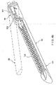
- One type of surgical device is a linear clamping, cutting and stapling device. Such a device may be employed in a surgical procedure to resect a cancerous or anomalous tissue from a gastro-intestinal tract. One conventional linear clamping, cutting and stapling instrument is shown in
Figure 1 . The device includes a pistol grip-styled structure having an elongated shaft and distal portion. The distal portion includes a pair of scissors-styled gripping elements, which clamp the open ends of the colon closed. In this device, one of the two scissors-styled gripping elements, such as the anvil portion, moves or pivots relative to the overall structure, whereas the other gripping element remains fixed relative to the overall structure. The actuation of this scissoring device (the pivoting of the anvil portion) is controlled by a grip trigger maintained in the handle. - In addition to the scissoring device, the distal portion also includes a stapling mechanism. The fixed gripping element of the scissoring mechanism includes a staple cartridge receiving region and a mechanism for driving the staples up through the clamped end of the tissue against the anvil portion, thereby sealing the previously opened end. The scissoring elements may be integrally formed with the shaft or may be detachable such that various scissoring and stapling elements may be interchangeable.
- One problem with the foregoing surgical devices, and in particular with the foregoing linear clamping, cutting and stapling devices such as that illustrated in
Figure 1 , is that the opposing jaws may be difficult to maneuver within a patient. It may be necessary for a surgeon to move the opposing jaws between various angles in order to position the desired tissue between the opposing jaws. However, it is also generally desirable to make an incision in a patient that is as small as possible, and the small size of an incision limits the degree to which the opposing jaws may be maneuvered. - Another problem with the foregoing surgical devices, and in particular with the foregoing linear clamping, cutting and stapling devices such as that illustrated in
Figure 1 , is that the opposing jaws may not be sufficiently hemostatic. Specifically, the opposing jaws of the foregoing surgical devices are not clamped together with sufficient force, thereby reducing the effectiveness of the surgical device. - Thus, there is believed to be a need for an improvement in the maneuverability of clamping, cutting and stapling devices. In addition, there is believed to be a need for a clamping, cutting and stapling device that provides additional clamping force.
- In accordance with an example embodiment of the present invention, a surgical device is provided that includes a jaw portion pivotably connected to a shaft portion about a hinge. The hinge defines an axis of rotation of these components that is perpendicular to one or both of the jaw portion and the shaft portion. The jaw portion, or a part thereof, may also be rotatable relative to the shaft portion about the longitudinal axis of the jaw portion.
- The jaw portion includes a first jaw and a second jaw. The second jaw is disposed in opposed correspondence with the first jaw. The first jaw may be pivotably coupled to the second jaw. The device may also include at least one of a cutting element and a stapling element disposed within the second jaw, preferably a blade rotatably mounted on a staple-driving wedge. The cutting element and/or the stapling element may be configured to move between a distal end and a proximal end of the second jaw to at least one of cut and staple a section of tissue disposed between the first and second jaws.
- In accordance with an example embodiment of the present invention, a surgical device is provided that includes a jaw portion. The jaw portion includes a first jaw and a second jaw moveable relative to the first jaw. The surgical device also includes a shaft portion coupled to a proximal end of the jaw portion. The surgical device further includes a driver configured to cause relative movement of the jaw portion and the shaft portion. The jaw portion defines a first longitudinal axis and the shaft portion defines a second longitudinal axis. The driver may be configured to cause the jaw portion to pivot relative to the shaft portion about a pivot axis that is perpendicular to the first and second longitudinal axes. The first and second jaws may be moveable relative to each other in a plane, the pivot axis being arranged parallel to the plane. Also, in accordance with an example embodiment of the present invention, the driver is also configured to cause at least a portion of the jaw portion to pivot relative to the shaft portion about the first longitudinal axis.
- The driver may be adapted to be driven by a first rotatable drive shaft and a second rotatable drive shaft. For instance, the driver may be configured such that rotation of the first and second rotatable drive shafts in opposite directions relative to each other causes the jaw portion to pivot relative to the shaft portion about the pivot axis. Also, the driver may be configured such that rotation of the first and second rotatable drive shafts in a same direction relative to each other causes the at least a portion of the jaw portion to rotate relative to the shaft portion about the first longitudinal axis. Furthermore, the driver may be configured such that rotation of the first rotatable drive shaft without rotating the second rotatable drive shaft causes relative movement of the first jaw and the second jaw.
- The surgical device may include a surgical member disposed within the first jaw. The surgical member may include a cutting element and/or a stapling element. The driver may be configured such that rotation of the second rotatable drive shaft without rotating the first rotatable drive shaft causes relative movement of the surgical member within the first jaw.
- In accordance with an example embodiment of the present invention, there is provided a surgical device that includes a jaw portion including a first jaw and a second jaw moveable relative to the first jaw, a shaft portion coupled to a proximal end of the jaw portion, and a driver adapted to be driven by first and second rotatable drive shafts such that selective rotation of the first and second rotatable drive shafts causes the surgical device to perform at least four different functions, e.g., movement of a first one of the jaw portion, the first jaw, the second jaw and the shaft portion relative to at least a second one of the jaw portion, the first jaw, the second jaw and the shaft portion.
- The jaw portion may define a first longitudinal axis, the first of the at least four different functions including the rotation of at least a portion of the jaw portion relative to the shaft portion about the first longitudinal axis. The driver is configured to be driven by rotation of the first and second rotatable drive shafts in a same direction relative to each other so as to cause the at least a portion of the jaw portion to rotate relative to the shaft portion about the first longitudinal axis. The shaft portion may define a second longitudinal axis, a second of the at least four different functions including pivoting the jaw portion relative to the shaft portion about a pivot axis that is perpendicular to the second longitudinal axis. The driver is configured to be driven by rotation of the first and second rotatable drive shafts in opposite directions relative to each other so as to cause the jaw portion to pivot relative to the shaft portion about the pivot axis. A third of the at least four different functions may include moving the first jaw relative to the second jaw. The driver is configured to be driven by the first rotatable drive shaft without rotation of the second rotatable drive shaft to cause relative movement of the first jaw and the second jaw. In addition, the surgical device may also include a surgical member, e.g., a cutting and/or stapling element, disposed within the first jaw, a fourth of the at least four different functions including relative movement of the surgical member within the first jaw. The driver is configured to be driven by rotation of the second rotatable drive shaft without rotation of the first rotatable drive shaft so as to cause relative movement of the surgical member within the first jaw.
- In accordance with an example embodiment of the present invention, there is provided a surgical device that includes a jaw portion, having a first jaw in opposed correspondence with a second jaw, the second jaw including a surgical member; a shaft portion coupled to a proximal end of the jaw portion; at least one motor configured to rotate the jaw portion relative to the shaft portion, to move the jaw portion relative to the shaft portion, move the first jaw relative to the second jaw and move the surgical member within the second jaw. The surgical member may be prevented from moving within the second jaw unless the first jaw is in a closed position relative to the second jaw.
- When the first jaw is in an open position relative to the second jaw, the jaw portion may be rotatable relative to the shaft portion. The surgical device may also include a gear element, and the gear element may be selectively engaged based upon a position of the first jaw relative to the second jaw. The gear element may be an idler gear that is moveable between a proximal position and a distal position. The surgical device may also include a cam block that is moveable between a proximal position and a distal position. The cam block may include a surface, and the cam block may be moved between its proximal and distal positions by engagement of the surface with a surface of one of the first and second jaws when the first and second jaws are moved relative to each other. The idler gear may be moved between its proximal and distal positions by engagement of the cam block with the idler gear.
- When the idler gear is in a distal position, the idler gear may engage recesses of a housing, and rotation of the idler gear by a drive element may cause the jaw portion to rotate relative to the shaft portion. When the idler gear is in a proximal position, the idler gear may be out of engagement with the recesses of the housing, such that the idler gear is rotatable relative to the housing, and rotation of the idler gear by the drive element may cause the surgical member to move within the second jaw. Advantageously, the surgical member may include a cutting element and/or a stapling element.
- In accordance with an example embodiment of the present invention, there is provided a method of using a surgical device, the surgical device including a jaw portion that has a first jaw in opposed correspondence with a second jaw, the second jaw including a surgical member, and a shaft portion coupled to a proximal end of the jaw portion. The method may include the steps of: operating at least one motor so as to selectively rotate the jaw portion relative to the shaft portion, move the jaw portion relative to the shaft portion, move the first jaw relative to the second jaw, and move the surgical member within the second jaw; and locking the surgical member from moving within the second jaw unless the first jaw is in a closed position relative to the second jaw.
- The method may also include the step of rotating the jaw portion relative to the shaft portion when the first jaw is in an open position relative to the second jaw. In addition, a gear element may be provided. The method may include the step of selectively engaging the gear element based upon a position of the first jaw relative to the second jaw. Providing the gear element may include providing an idler gear that is moveable between a proximal position and a distal position. A cam block may be provided that is moveable between a proximal position and a distal position.
- The cam block may include a surface, and the method may include the step of moving the cam block between its proximal and distal positions by engagement of the surface with a surface of one of the first and second jaws when the first and second jaws are moved relative to each other. The idler gear may be moved between its proximal and distal positions by engagement of the cam block with the idler gear. The idler gear may engage recesses of a housing when the idler gear is in a distal position. When the idler gear engages the recesses of the housing, rotation of the idler gear by a drive element may cause the jaw portion to rotate relative to the shaft portion.
- The method may also include the steps of moving the idler gear to a proximal position such that the idler gear is out of engagement with the recesses of the housing and rotating the idler gear relative to the housing. Upon rotating the idler gear by the drive element, the surgical member may be moved within the second jaw. Advantageously, the surgical member includes at least one of a cutting element and a stapling element, and the step of moving the surgical member includes at least one of cutting and stapling a section of tissue.
-
-
Figure 1 is a perspective view of a conventional linear clamping, cutting and stapling device; -
Figure 2(a) is a perspective view of an example embodiment of an electro-mechanical driver component, according to the present invention; -
Figure 2(b) is a schematic diagram that illustrates some of the components of a surgical device, according to an example embodiment of the present invention; -
Figure 3(a) is a perspective view of a surgical device, according to an example embodiment of the present invention; -
Figure 3(b) is a rear perspective view that illustrates some of the internal components of the surgical device, according to one embodiment of the present invention; -
Figure 3(c) is a side perspective view that illustrates some of the internal components of the surgical device, according to one embodiment of the present invention; -
Figure 3(d) is a perspective view that illustrates a jaw portion being fully pivoted, e.g., articulated, relative to a shaft portion, according to one embodiment of the present invention; -
Figure 3(e) is a bottom perspective view that illustrates the jaw portion being fully pivoted relative to the shaft portion, according to one embodiment of the present invention; -
Figure 3(f) is an exploded view of a replaceable staple cartridge, according to one embodiment of the present invention; -
Figure 3(g) is a cross-sectional view of the surgical device, according to one embodiment of the present invention, in a fully closed position; -
Figure 3(h) is a bottom view of a first jaw, according to another example embodiment of the present invention; -
Figure 3(i) to 3(l) are side cross-sectional views that illustrate the opening and closing of first and second jaws, according to another example embodiment of the present invention; -
Figure 4(a) is a perspective view of an articulating clamping, cutting and stapling attachment, according to another example embodiment of the present invention; -
Figure 4(b) is a perspective view that illustrates additional features of the second jaw of the jaw portion, according to an example embodiment of the present invention; -
Figure 5(a) is a perspective view that illustrates the proximal end of the second jaw, according to an example embodiment of the present invention; -
Figure 5(b) illustrates the surgical device ofFigure 4(a) when moved into a first partially closed position; -
Figure 5(c) illustrates the surgical device ofFigure 4(a) when moved into a second partially closed position; -
Figure 5(d) illustrates the surgical device ofFigure 4(a) when moved into a fully closed position; -
Figure 6(a) illustrates a flexible shaft and a first coupling, according to an example embodiment of the present invention; -
Figure 6(b) illustrates a rear perspective view of the first coupling, according to an example embodiment of the present invention; -
Figure 6(c) illustrates a front perspective view of the first coupling, according to the example embodiment shown inFigure 6(b) ; -
Figure 6(d) is a side perspective view of some of the internal components of the first coupling, according to an example embodiment of the present invention; -
Figure 6(e) is a rear perspective view of the second coupling at the distal end of the flexible shaft, according to an example embodiment of the present invention; -
Figure 7 illustrates a side view, partially in section, of the flexible shaft, according to another example embodiment of the present invention; -
Figure 8 is a cross-sectional view of the flexible shaft taken along the line 8-8 illustrated inFigure 7 ; -
Figure 9 illustrates a rear end view of first coupling, according to an example embodiment of the present invention; -
Figure 10 , there is seen a front end view of the second coupling of the flexible shaft, according to an example embodiment of the present invention; -
Figure 11 illustrates schematically an arrangement of motors, according to an example embodiment of the present invention; -
Figure 12 illustrates a schematic view of the electro-mechanical driver component, according to an example embodiment of the present invention; -
Figure 13 is a schematic view of an encoder, according to an example embodiment of the present invention; -
Figure 14 schematically illustrates the memory module, according to an example embodiment of the present invention; -
Figure 15 , there is seen a schematic view of a wireless RCU, according to an example embodiment of the present invention; -
Figure 16 , there is seen a schematic view of a wired RCU, according to an example embodiment of the present invention; -
Figure 17 is a side cross-sectional view of a surgical device, according to an example embodiment of the present invention; -
Figure 18 is a perspective view of some of the internals components of the surgical device ofFigure 17 ; and -
Figure 19 is rear perspective view of some of the internals components of the surgical device ofFigure 17 . -
Figure 2(b) is a schematic diagram that illustrates some of the components of asurgical device 11, according to an example embodiment of the present invention. Thesurgical device 11 is configured so as to be particularly well-suited for insertion into the body of a patient, e.g., via a cannula (not shown). In the embodiment shown, thesurgical device 11 is a clamping, cutting and stapling device. Thesurgical device 11 includes ajaw portion 11a that is pivotably coupled to ashaft portion 11b by ahinge portion 11c. Thejaw portion 11a includes afirst jaw 50 having adistal end 50a and aproximal end 50b, and asecond jaw 80 having adistal end 80a and aproximal end 80b. Thefirst jaw 50 and thesecond jaw 80 are pivotably coupled relative to each other at or near their respective proximal ends 50b, 80b. In the example embodiment shown, thefirst jaw 50 and thesecond jaw 80 pivot relative to each other about pivot axis A, which is oriented perpendicular to the page. - As mentioned above, the
jaw portion 11a is pivotably coupled to theshaft portion 11b by thehinge portion 11c. Specifically, thejaw portion 11a is pivotable relative to theshaft portion 11b about a pivot axis B, which may be positioned at any location on or between thejaw portion 11a and theshaft portion 11b, and at any circumferential location relative to thejaw portion 11a and theshaft portion 11b. In the example embodiment shown, the pivot axis B is oriented vertically in the view shown, such that, upon articulation, thejaw portion 11a pivots within a plane that is perpendicular to the page. It should be recognized that, in other example embodiments, the pivot axis B may have a different orientation, so as to enable thejaw portion 11a to pivot within a different plane. Thejaw portion 11a may be pivotable to and between any angles relative to theshaft portion 11b, such that thejaw portion 11a can be selectively positioned as desired during use. Multiple pivot axes relative to the longitudinal axis of theshaft portion 11b (the longitudinal axis of theshaft portion 11b is designated as axis D inFigure 2(b) ) may be provided. For instance, in various embodiments, thejaw portion 11a may be rotatable relative to theshaft portion 11b about its longitudinal axis D, or may be rotatable relative to theshaft portion 11b about multiple pivot axes that are perpendicular to the longitudinal axis D. - The
shaft portion 11b may include adistal portion 1101, to which thejaw portion 11a is connected, and aproximal portion 1102. Theproximal portion 1102 of theshaft portion 11b may include ahandle 1103, with which a user may grasp thesurgical device 11. At a proximal-most end of theproximal portion 1102, theshaft portion 11b may include aconnection element 1104, e.g., a quick-connect coupling, for connecting to a flexible shaft (described in further detail below). - The
second jaw 80 includes aclamping surface 106. Thesecond jaw 80 also includes a cutting and staplingelement 104, which may form at least part of the clampingsurface 106 of thesecond jaw 80. Thefirst jaw 50 includes ananvil member 700 in opposed correspondence with thesecond jaw 80. Theanvil member 700 includes the clampingsurface 108, which, along with the clampingsurface 106 of thesecond jaw 80, clamps a section of tissue to be cut and stapled. As explained in greater detail below, the cutting and staplingelement 104 is configured to cut and staple a section of tissue when thefirst jaw 50 and thesecond jaw 80 are in a closed, e.g., fully closed, position. Additional features of the cutting and staplingelement 104, according to an embodiment, are illustrated and described, for instance, in connection withFigures 3(f) and3(g) below, and further inU.S. Patent Application Serial Nos. 09/999,546, filed November 30, 2001 10/460,291, filed June 11, 2003 - Various drivers may be employed to drive the movements of the
surgical device 11, e.g., pivoting thejaw portion 11a relative to theshaft portion 11b, rotating thejaw portion 11a or some part thereof around its longitudinal axis relative to theshaft portion 11b, pivoting thefirst jaw 50 relative to thesecond jaw 80, firing of a staple cartridge, etc. According to one embodiment of the present invention, these functions are performed by connection of thesurgical device 11 to a flexible shaft having two rotatable drive shafts, although is should be recognized that in other embodiments, different types and/or a different number of drive components may be employed. -
Figure 2(b) illustrates schematically an embodiment wherein thesurgical device 11 employs first andsecond drivers first driver 88 may, e.g., operate to move thefirst jaw 50 and thesecond jaw 80 relative to each other. Thefirst driver 88 may include any type of drive mechanism capable of moving thefirst jaw 50 and thesecond jaw 80 relative to each other. Thefirst driver 88 may be situated at least partially in theproximal end 80b of thesecond jaw 80 and may be connected to theproximal end 50b of thefirst jaw 50. Thefirst driver 88 may engage theproximal end 50b of thefirst jaw 50 so as to open and close thefirst jaw 50 relative to thesecond jaw 80. In addition, thefirst driver 88 may extend through theshaft portion 11b of thesurgical device 11 to afirst drive socket 654. Thefirst drive socket 654 of thefirst driver 88 is coupled to afirst motor 96 by afirst drive shaft 94. As will be explained in more detail below, thefirst driver 88, when engaged by thefirst motor 96 via thefirst drive shaft 94, may operate to open and closefirst jaw 50 relative tosecond jaw 80, in addition to performing other operations of thesurgical device 11. - The
second jaw 80 also includes asecond driver 98. Thesecond driver 98 may also extend through theshaft portion 11b of thesurgical device 11 to asecond drive socket 694. Thesecond drive socket 694 is coupled to asecond motor 100 by asecond drive shaft 102. Thesecond driver 98, when engaged by thesecond motor 100 via thesecond drive shaft 102, may operate to drive the cutting and staplingelement 104 to cut and staple a section oftissue 52, in addition to performing other operations of thesurgical device 11. - While two drive sockets, e.g., the
first drive socket 654 and thesecond drive socket 694, and two corresponding drive shafts, e.g., thefirst drive shaft 94 and thesecond drive shaft 102, are illustrated as being part of thesurgical device 11 and as being for the purposes of clamping, cutting and stapling a section of tissue, it is possible to provide any suitable number of drive sockets and drive shafts. For example, a single drive shaft may be provided to perform the above-described functions of thesurgical device 11. - In one embodiment, the two drive shafts, e.g., the
first drive shaft 94 and thesecond drive shaft 102, are also configured to be employed to move thejaw portion 11a relative to theshaft portion 11b. An example of this type of embodiment is illustrated in, e.g.,Figures 3(a) through 3(e) , and is described further below. Alternatively, and as shown inFigure 2(b) , thesurgical device 11 may also include athird driver 201 and afourth driver 202 that are employed to move thejaw portion 11a relative to theshaft portion 11b. For instance, thethird driver 201 may be configured to pivot thejaw portion 11a about axis B relative to theshaft portion 11b, while thefourth driver 202 may be configured to rotate thejaw portion 11a about its longitudinal axis D relative to theshaft portion 11b. In one embodiment, the third andfourth drivers shaft portion 11b of thesurgical device 11 to third andfourth drive sockets 2011, 2021, respectively. Thethird drive socket 2011 is coupled to athird motor 2013 by athird drive shaft 2012. Thethird driver 201, when engaged by thethird motor 2013 via thethird drive shaft 2012, operates to pivot thejaw portion 11a about axis B relative to theshaft portion 11b. The fourth drive socket 2021 is coupled to afourth motor 2023 by a fourth drive shaft 2022. Thefourth driver 202, when engaged by thefourth motor 2023 via the fourth drive shaft 2022, operates to rotate thejaw portion 11a about its longitudinal axis D relative to theshaft portion 11b. - The drive shafts, e.g., first and second
rotatable drive shafts flexible drive shaft 1620 illustrated inFigure 2(a) . Other types of flexible drive shafts may also be employed. For instance, the drive shafts may be housed within a flexible drive shaft of the type described and illustrated in Applicant's co-pending Provisional Patent App. Designated as Attorney Docket No. 11443/210, which is expressly incorporated by reference herein in its entirety. - Referring to
Figure 2(b) , thesurgical device 11 may also include amemory module 6041. In one embodiment, thememory module 6041 is connected to or integral with the cutting and staplingelement 104. Thememory module 6041 is connected to adata connector 1272 by adata transfer cable 1278. Additional features of these components are set forth in connection withFigures 3(f) and7 . - Furthermore,
Figure 2(b) also illustrates aconnection element 1104. Theconnection element 1104 may include aquick connect sleeve 713 that hasquick connect slots 713a that engage complementaryquick connect elements 1664 of aflexible drive shaft 1620, which is described in further detail below. In order to retain thequick connect elements 1664 of theflexible drive shaft 1620 in thequick connect slots 713a of thequick connect sleeve 713, theconnection element 1104 may also include a spring. - According to an example embodiment of the present invention, the
surgical device 11 may be configured as an attachment to, or may be integral with, an electro-mechanical surgical system, such as the electro-mechanical driver component 1610 having a motor system illustrated inFigure 2(a) . It should be appreciated that, in this example embodiment, any appropriate number of motors may be provided, and the motors may operate via battery power, line current, a DC power supply, an electronically controlled DC power supply, etc. It should also be appreciated that the motors may be connected to a DC power supply, which is in turn connected to line current and which supplies the operating current to the motors. In another example embodiment, the surgical device may be an attachment to, or may integral with, a mechanical driver system. -
Figure 3(a) is a perspective view of asurgical device 11, according to one embodiment of the present invention. As set forth above,Figures 3(a) to 3(e) illustrate one embodiment of the present invention in which two drive shafts are configured to be employed to move thejaw portion 11a relative to theshaft portion 11b, to rotate thejaw portion 11a about its longitudinal axis, to move thefirst jaw 50 relative to thesecond jaw 80, and to fire a stapling and cutting cartridge. In the position shown inFigure 3(a) , thejaw portion 11a is positioned at an angle of approximately 60 degrees relative to theshaft portion 11b. Thejaw portion 11a may be appropriately positioned according to the incision made in the patient and to the position of the tissue desired to be clamped, cut and stapled. -
Figure 3(b) is a rear perspective view that illustrates some of the internal components of thesurgical device 11, according to an example embodiment of the present invention. The outer body of thesurgical device 11 is shown in ghost lines. As shown, thejaw portion 11a is in an initial position in which it is axially aligned with theshaft portion 11b. -
Figure 3(b) shows a firstrotatable drive shaft 500, which may be axially rotatable within theshaft portion 11b. Coupled to the firstrotatable drive shaft 500 is agear element 502. Thegear element 502 rotates about a longitudinal axis and is meshingly engaged with agear element 504. Thegear element 504 is held in position bypin 505, the central axis of which is coaxial with the pivot axis B around which thejaw portion 11a pivots relative to theshaft portion 11b. - The
gear element 504 is also meshingly engaged with agear element 506 within thejaw portion 11a. Thegear element 506 is connected to agear element 510 by ashaft 508. Thegear element 506, thegear element 510, and theshaft 508 rotate within thejaw portion 11a about a longitudinal axis defined by the central axis of theshaft 508. Thegear element 510 is meshingly engaged with agear element 512 that rotates about apin 513 that is longitudinally arranged within thejaw portion 11a. Thegear element 512 is meshingly engaged with agear element 514. Thegear element 514 has a shaft portion that extends distally to a set ofteeth 516. Theteeth 516 are selectively engageable with a correspondingly-shaped opening in aplate 518, theplate 518 being keyed to an internal surface of thesurgical device 11 so as to prevent relative rotation of theplate 518. Theplate 518 is moveable in an axial direction between a first position, in which the correspondingly-shaped opening in theplate 518 is locked in engagement with theteeth 516, and a second position, in which theplate 518 is moved distally relative to the first position and the correspondingly-shaped opening in theplate 518 is not in engagement with theteeth 516. - Extending distally from the
gear 514 and the shaft portion carrying theteeth 516 is a threadedscrew 520. The threadedscrew 520 is arranged longitudinally and is configured to rotate about a longitudinal axis when thegear 514 is rotated. Mounted on the threadedscrew 520 is apush block 522. Thepush block 522 is keyed to an internal surface of thesurgical device 11, so as to prevent relative rotation of thepush block 520. Rotatably coupled to the lower distal end of thepush block 520 is a pair ofrollers 524. The pair ofrollers 524 are seated withinrespective slots 5011 on each side of theupper jaw 50. Theupper jaw 50 and theslots 5011 are shown in dotted line inFigure 3(b) . -
Figure 3(b) also shows a secondrotatable drive shaft 550, which may be axially rotatable within theshaft portion 11b. Coupled to the secondrotatable drive shaft 550 is agear element 552. Thegear element 552 rotates about a longitudinal axis and is meshingly engaged with agear element 554. Thegear element 554 is held in position bypin 505, the central axis of which is coaxial with the pivot axis B around which thejaw portion 11a pivots relative to theshaft portion 11b. - The
gear element 554 is also meshingly engaged with agear element 556 within thejaw portion 11a. Thegear element 556 is connected to agear element 560 by ashaft 558. Thegear element 556, thegear element 560, and theshaft 558 rotate within thejaw portion 11a about a longitudinal axis defined by the central axis of theshaft 558. Thegear element 560 is meshingly engaged with agear element 562a that is mounted on a proximal end of thepin 513. Thegear element 562a is configured to adapted to be non-rotatably mounted on, and thus to rotate with, thepin 513, thepin 513 extending longitudinally within thejaw portion 11a. In addition, agear element 562b is adapted to be non-rotatably mounted on a distal end of thepin 513. Thus, thegear element 562b is also configured to rotate with thepin 513. - The
gear element 562b has a shaft portion that extends distally and includes a set of teeth 5661 (hidden from view inFigure 3(b) but shown inFigure 3(d) ). Theteeth 5661 are selectively engageable with a correspondingly-shaped opening in theplate 518. As set forth above, theplate 518 is keyed to an internal surface of thesurgical device 11 so as to prevent relative rotation of theplate 518, and is moveable in an axial direction between the first position, in which the correspondingly-shaped opening in theplate 518 is locked in engagement with theteeth 5661, and the second position, in which theplate 518 is moved distally relative to the first position and the correspondingly-shaped opening in theplate 518 is not in engagement with theteeth 5661. - The
gear element 562b is meshingly engaged with agear element 564. Extending distally from thegear 564 is a firstlongitudinal rod 566. The firstlongitudinal rod 566 is attached to a secondlongitudinal rod 568. The secondlongitudinal rod 568 has ashoulder 572. Between the firstlongitudinal rod 566 and theshoulder 572 of the secondlongitudinal rod 568 is a spring. Thedistal end 574 of the secondlongitudinal rod 568 is configured to engage a respective opening in awedge driver 605. Thewedge driver 605 rotates so as to drive a stapling/cutting wedge (described in further detail below) along a staple cartridge. - These components are also shown in various other views. For instance,
Figure 3(c) is a side perspective view that illustrates some of the internal components of thesurgical device 11. As shown, thejaw portion 11a is pivoted, e.g., articulated, relative to theshaft portion 11b. In addition,Figure 3(d) is a perspective view that illustrates thejaw portion 11a being further pivoted, e.g., articulated, relative to theshaft portion 11b. Also,Figure 3(e) is a bottom perspective view that illustrates thejaw portion 11a being pivoted, e.g., articulated, relative to theshaft portion 11b. - As set forth above, the
surgical device 11 may also include a cutting and staplingelement 104. In one embodiment, the staple and cuttingelement 104 is a staple cartridge.Figure 3(f) is an exploded view of areplaceable staple cartridge 600. Thereplaceable staple cartridge 600 is one type of stapling/cutting arrangement that may be employed as the cutting and staplingelement 104 in the example embodiment of the present invention illustrated inFigures 3(a) to 3(e) . Thereplaceable staple cartridge 600 includes astaple tray 604. Thestaple tray 604 has a slot 604i at itsproximal end 604d in which thememory module 6041 is retained by amemory module retainer 6042. Thememory module 6041 may store information as described, for example, inU.S. Patent Application Serial No. 09/723,715, filed on November 28, 2000 issued as U.S. Patent No. 6,793,652 on September 21, 2004 ,U.S. Patent Application Serial No. 09/836,781, filed on April 17, 2001 U.S. Patent Application Serial No. 09/887,789, filed on June 22, 2001 U.S. Patent Application Serial No. 10/099,634, filed on March 15, 2002 wedge driver 605 is configured to be rotatably disposed through acentral channel 604e of thestaple tray 604. Specifically, thewedge driver 605 has adistal end 605a that is configured to be rotatably mounted within adistal orifice 604a of thestaple tray 604. Thewedge driver 605 also includes an externally threadedregion 605b, anon-threaded portion 605c that rotatably extends through aproximal orifice 604b in theproximal end 604b of thestaple tray 604, and a proximally-facingopening 605d at its proximal-most end for receiving thedistal end 574 of the secondlongitudinal rod 568. The proximally-facingopening 605d and thedistal end 574 of the secondlongitudinal rod 568 are adapted for non-rotatable coupling relative to each other when thedistal end 574 of the secondlongitudinal rod 568 is received, e.g., inserted, within the proximally-facingopening 605d. - The
replaceable staple cartridge 600 also includes awedge 603 having an internally threadedbore 603a. The externally threadedregion 605b of thewedge driver 605 is configured to extend through the internally threadedbore 603a of thewedge 603. The threads of the internally threadedbore 603a of thewedge 603 match the threads of the externally threadedregion 605b of thewedge driver 605. As is discussed further below, upon rotation of thewedge driver 605, thewedge 603 is moved between thedistal end 604c of thestaple tray 604 and theproximal end 604d of thestaple tray 604 through acentral channel 604e. - The
staple tray 604 also includes a plurality of vertically-disposedslots 604f in opposingwalls 604g of thecentral channel 604e. On each side of thecentral channel 604e, astaple pusher 607 is configured to be slideably disposed within theslots 604f. More specifically, each of thestaple pushers 607 has atop surface 607a running longitudinally between tworows 607b ofstaple pushing fingers 607c. Thestaple pushing fingers 607c are configured such that eachstaple pushing finger 607c in therow 607b that abuts thewall 604g of thestaple tray 604 is retained within acorresponding slot 604f of thewall 604g so as to be vertically slideable therein. Thestaple pushing fingers 607c are positioned overslots 604h in thestaple tray 604. Theslots 604h in thestaple tray 604 house a plurality of fasteners, e.g.,staples 606. Each of thestaples 606 includes abutt 606a and a pair ofprongs 606b. - The
wedge 603 also includes a pair of slopededges 603b that slideably engage respectivetop surfaces 607a of thestaple pushers 607. When thewedge 603 is moved from thedistal end 604c to theproximal end 604d of thestaple tray 604 through thecentral channel 604e, the pair of slopededges 603b of thewedge 603 is configured to slideably engage the respectivetop surfaces 607a of thestaple pushers 607 in order to successively push thestaple pushing fingers 607c of thestaple pushers 607 into, and thus thestaples 606 out of, theslots 604h in thestaple tray 604. Acartridge top 611 is configured to fit over thecentral channel 604a of thestaple tray 604, while astaple retainer 610 is configured to cover theclamping surface 106 of thestaple tray 604. Additional features, e.g., ablade 51, of thestaple cartridge 600 are described below in connection withFigure 3(g) , these features being described during operation of thesurgical device 11. -
Figure 3(h) is a bottom view of thefirst jaw 50. Thefirst jaw 50 includes ananvil member 700 having a longitudinally-disposedslot 701 that extends from a distal end to a proximal end of theanvil member 700. Theslot 701 is aligned with theblade 51 of thesecond jaw 80 so that theblade 51 extends into and travels along theslot 701 when the blade is moved from thedistal end 80a to theproximal end 80b of thesecond jaw 80. Theanvil member 700 also includes a plurality ofrows 702 of staple guides 703. The staple guides 703 are configured to receive theprongs 606b of thestaples 606 and to bend theprongs 606b so as to close thestaples 606. When thesurgical device 11 is in the closed position, therows 702 of the staple guides 703 align with theslots 604h of thestaple tray 604 in thesecond jaw 80. - In operation, the
jaw portion 11a is maintained in an initial position in which it is axially aligned with theshaft portion 11b, such as the position shown inFigure 3(b) . In this position, thesurgical device 11 may be inserted, e.g., through a trocar, into a surgical site. Depending on the position of the incision and the tissue to be clamped, stapled and cut, the user may then articulate thejaw portion 11a relative to theshaft portion 11b. - In a first articulation process, the
jaw portion 11a is pivoted relative to theshaft portion 11b. Theplate 518 is arranged in its first position, e.g., such that the two openings in theplate 518 are locked in respective engagement with theteeth 516 ofgear element 514 and with theteeth 5661 of thegear element 562b. The firstrotatable drive shaft 500 and the secondrotatable drive shaft 550 are then rotated in opposite directions. For instance, referring toFigure 3(b) , in order to articulate thejaw portion 11a in a clockwise direction relative to theshaft portion 11b (when viewed from above), the firstrotatable drive shaft 500 may be rotated in a counter-clockwise direction (for the sake of simplicity, all references herein to a rotational direction, e.g., clockwise or counterclockwise, refer to a view from the proximal end of the surgical device towards the distal end of thesurgical device 11, unless otherwise noted). Thegear element 502 attached to the firstrotatable drive shaft 500 is thus also caused to rotate in a counter-clockwise direction. By virtue of its engagement with thegear element 504, the counter-clockwise rotation of thegear element 502 causes thegear element 504 to rotate in a counter-clockwise direction (when viewed from above) about thepin 505. By virtue of its engagement with thegear element 506, the counter-clockwise rotation of thegear element 504 causes thegear element 506 to rotate in a clockwise direction. - Simultaneously, the second
rotatable drive shaft 550 may be rotated in a clockwise direction. Thegear element 552 attached to the secondrotatable drive shaft 550 is thus also caused to rotate in a clockwise direction. By virtue of its engagement with thegear element 554, the clockwise rotation of thegear element 552 causes thegear element 554 to rotate in a counter-clockwise direction (when viewed from above) about thepin 505. By virtue of its engagement with thegear element 556, the clockwise rotation of thegear element 554 causes thegear element 556 to rotate in a counter-clockwise direction. The engagement of theplate 518 with theteeth gear elements surgical device 11. Thus, thejaw portion 11a is caused to rotate in a clockwise direction relative to theshaft portion 11b (when viewed from above). To rotate thejaw portion 11a in the opposite direction, e.g., counter-clockwise relative to theshaft portion 11b when viewed from above, the direction of rotation of the first and secondrotatable drive shafts - Once the
jaw portion 11a is rotated about thepin 505 to a desired position, thejaw portion 11a may also be rotated, in a second articulation process, relative to theshaft portion 11b about the longitudinal axis of thejaw portion 11a, e.g., illustrated as axis D. Theplate 518 is maintained in its first position, such that the two openings in theplate 518 are locked in respective engagement with theteeth 516 ofgear element 514 and with theteeth 5661 of thegear element 562b. The firstrotatable drive shaft 500 and the secondrotatable drive shaft 550 are then rotated in the same direction. For instance, referring toFigure 3(b) , in order to rotate thejaw portion 11a about its longitudinal axis in a counter-clockwise direction relative to theshaft portion 11b, the firstrotatable drive shaft 500 may be rotated in a counter-clockwise direction. Thegear element 502 attached to the firstrotatable drive shaft 500 is thus also caused to rotate in a counter-clockwise direction. By virtue of its engagement with thegear element 504, the counter-clockwise rotation of thegear element 502 causes thegear element 504 to rotate in a counter-clockwise direction (when viewed from above) about thepin 505. By virtue of its engagement with thegear element 506, the counter-clockwise rotation of thegear element 504 causes thegear element 506 to rotate in a clockwise direction. Since thegear element 506 is attached to thegear element 510 by theshaft 508, rotation of thegear element 506 in the clockwise direction causes thegear element 510 to also rotate in a clockwise direction. By virtue of its engagement with thegear element 512, the clockwise rotation of thegear element 510 causes thegear element 512 to rotate in a counter-clockwise direction. - The second
rotatable drive shaft 550 may also be rotated in a counter-clockwise direction. Thegear element 552 attached to the secondrotatable drive shaft 550 is thus also caused to rotate in a counter-clockwise direction. By virtue of its engagement with thegear element 554, the counter-clockwise rotation of thegear element 552 causes thegear element 554 to rotate in a clockwise direction (when viewed from above) about thepin 505. By virtue of its engagement with thegear element 556, the clockwise rotation of thegear element 554 causes thegear element 556 to rotate in a clockwise direction. Since thegear element 556 is attached to thegear element 560 by theshaft 558, rotation of thegear element 556 in the clockwise direction causes thegear element 560 to also rotate in a clockwise direction. By virtue of its engagement with thegear element 562a, the clockwise rotation of thegear element 560 causes thegear element 562a to rotate in a counter-clockwise direction. Also, since both thegear element 562a and thegear element 562b are adapted to be non-rotatably mounted to, e.g., keyed to, thepin 513, the rotation of thegear element 562a in a counter-clockwise direction also causes thegear element 562b to rotate in a counter-clockwise direction. - Thus, the
gear element 562b and thegear element 512 rotate together in a counter-clockwise direction about their shared longitudinal axes, e.g., the central axis of thepin 513. Since theplate 518 is maintained in its first position, the two openings in theplate 518 are locked in respective engagement with theteeth 516 ofgear element 514 and with theteeth 5661 of thegear element 562b. Thus, the rotation of thegear element 562b, and of thegear element 512 in the counter-clockwise direction about thepin 513, causes thegear element 514 and thegear element 564 to also rotate in a counter-clockwise direction about thepin 513, the central axis of which is coaxial with the longitudinal axis D of thejaw portion 11a. The gear element is connected to thescrew 520, on which is mounted thepush block 522. Since thepush block 522 is keyed to the internal surface of thejaw portion 11a, the rotation of thegear element 514 about the longitudinal axis D causes thejaw portion 11a to rotate relative to theshaft portion 11b about its longitudinal axis D. - Once the
jaw portion 11a is rotated relative to theshaft portion 11b about its longitudinal axis D to a desired position, thejaws plate 518 is moved distally to its second position, such that the two openings in theplate 518 are not locked in respective engagement with either theteeth 516 ofgear element 514 nor with theteeth 5661 of thegear element 562b. The firstrotatable drive shaft 500 is then rotated in a first direction while the secondrotatable drive shaft 550 is not rotated. For instance, referring toFigure 3(b) , in order to open thefirst jaw 50 relative to thesecond jaw 80, the firstrotatable drive shaft 500 may be rotated in a counter-clockwise direction. Thegear element 502 attached to the firstrotatable drive shaft 500 is thus also caused to rotate in a counter-clockwise direction. By virtue of its engagement with thegear element 504, the counter-clockwise rotation of thegear element 502 causes thegear element 504 to rotate in a counter-clockwise direction (when viewed from above) about thepin 505. By virtue of its engagement with thegear element 506, the counter-clockwise rotation of thegear element 504 causes thegear element 506 to rotate in a clockwise direction. Since thegear element 506 is attached to thegear element 510 by theshaft 508, rotation of thegear element 506 in the clockwise direction causes thegear element 510 to also rotate in a clockwise direction. By virtue of its engagement with thegear element 512, the clockwise rotation of thegear element 510 causes thegear element 512 to rotate in a counter-clockwise direction. By virtue of its engagement with thegear element 514, the counter-clockwise rotation of thegear element 512 causes thegear element 514 to rotate in a clockwise direction. Since theplate 518 is moved to its second position, thegear element 512 rotates about thepin 513 without thepin 513 rotating. - The clockwise rotation of the
gear element 514 causes rotation of the threadedscrew 520 in a clockwise direction. In an initial stage of operation, e.g., when thesurgical device 11 has first been inserted into a patient's body, thepush block 522 is located in a distal-most position along the threadedscrew 520. Rotation of the threadedscrew 520 causes thepush block 522, which is adapted to be non-rotatably mounted within, e.g., keyed to, an internal surface of thesurgical device 11, to travel in a proximal direction. The proximal movement of the push block 522 causes the pair ofrollers 524 to move proximally within theirrespective slots 5011 on each side of theupper jaw 50. When thepush block 522 has moved to the proximal end of the threadedscrew 520, therollers 524 are positioned at a proximal end of theslots 5011, at which position thefirst jaw 50 is maximally opened relative to thesecond jaw 80. - Once the first and
second jaws jaws plate 518 in its second position, e.g., such that the two openings in theplate 518 are not locked in respective engagement with either theteeth 516 ofgear element 514 nor with theteeth 5661 of thegear element 562b, the firstrotatable drive shaft 500 is rotated in a second direction while the secondrotatable drive shaft 550 is not rotated. For instance, referring toFigure 3(b) , in order to close thefirst jaw 50 relative to thesecond jaw 80, the firstrotatable drive shaft 500 may be rotated in a clockwise direction. Thegear element 502 attached to the firstrotatable drive shaft 500 is thus also caused to rotate in a clockwise direction. By virtue of its engagement with thegear element 504, the clockwise rotation of thegear element 502 causes thegear element 504 to rotate in a clockwise direction (when viewed from above) about thepin 505. By virtue of its engagement with thegear element 506, the clockwise rotation of thegear element 504 causes thegear element 506 to rotate in a counter-clockwise direction. Since thegear element 506 is attached to thegear element 510 by theshaft 508, rotation of thegear element 506 in the counter-clockwise direction causes thegear element 510 to also rotate in a counter-clockwise direction. By virtue of its engagement with thegear element 512, the counter-clockwise rotation of thegear element 510 causes thegear element 512 to rotate in a clockwise direction. By virtue of its engagement with thegear element 514, the clockwise rotation of thegear element 512 causes thegear element 514 to rotate in a counter-clockwise direction. Since theplate 518 is moved to its second position, thegear element 512 rotates about thepin 513 without thepin 513 rotating. - The counter-clockwise rotation of the
gear element 514 causes rotation of the threadedscrew 520 in a counter-clockwise direction. As set forth above, thepush block 522 may be located in a proximal-most position along the threadedscrew 520. Rotation of the threadedscrew 520 causes thepush block 522, which is keyed to an internal surface of thesurgical device 11, to travel in a distal direction. The distal movement of the push block 522 causes the pair ofrollers 524 to move distally within theirrespective slots 5011 on each side of theupper jaw 50. When thepush block 522 has moved to the distal end of the threadedscrew 520, therollers 524 are positioned at a distal end of theslots 5011, at which position thefirst jaw 50 is maximally clamped against thesecond jaw 80. It should be noted that, while the opening and closing of the first andsecond jaws second jaws Figures 3(f) through 3(i) . - Once a section of tissue has been clamped between the first and
second jaws surgical device 11 may employ only one such element, or else may employ a different type of surgical instrument. Before thesurgical device 11 is inserted into a patient's body, a staple cartridge 578 is provided within thesecond jaw 80. In one embodiment, thesurgical device 11 is a single use device, in which the staple cartridge is integral to thesecond jaw 80. Alternatively, thesurgical device 11 may have a replaceable staple cartridge, e.g.,replaceable staple cartridge 600 as illustrated inFigure 3(f) , thereby permitting thesurgical device 11 to be used numerous times with different staple cartridges. In this embodiment, if thesurgical device 11 is being used for the first time, thestaple cartridge 600 may be pre-installed during manufacture and assembly of thesurgical device 11, or else may be installed by the user just prior to using thesurgical device 11. If thesurgical device 11 is being used for the second or more time, thestaple cartridge 600 may be installed by the user just prior to using thesurgical device 11. When thestaple cartridge 600 is inserted into thesecond jaw 80, thedistal end 574 of thelongitudinal rod 568 is received within theproximally facing opening 605d of thewedge driver 605. - To illustrate the cutting/stapling operation of the
surgical device 11, reference is first made toFigure 3(b) . With thestaple cartridge 600 installed within thesecond jaw 80 of thesurgical device 11, theplate 518 is maintained in its second position, such that the two openings in theplate 518 are not locked in respective engagement with either theteeth 516 ofgear element 514 nor with theteeth 5661 of thegear element 562b. The secondrotatable drive shaft 550 is then rotated in a first direction while the firstrotatable drive shaft 500 is not rotated. For instance, in order to cut and staple a section of tissue disposed between the first andsecond jaw rotatable drive shaft 550 may be rotated in a counter-clockwise direction. Thegear element 552 attached to the secondrotatable drive shaft 550 is thus also caused to rotate in a counter-clockwise direction. By virtue of its engagement with thegear element 554, the counter-clockwise rotation of thegear element 552 causes thegear element 554 to rotate in a clockwise direction (when viewed from above) about thepin 505. By virtue of its engagement with thegear element 556, the clockwise rotation of thegear element 554 causes thegear element 556 to rotate in a clockwise direction. Since thegear element 556 is attached to thegear element 560 by theshaft 558, rotation of thegear element 556 in the clockwise direction causes thegear element 560 to also rotate in a clockwise direction. By virtue of its engagement with thegear element 562a, the clockwise rotation of thegear element 560 causes thegear elements gear element 564, the counter-clockwise rotation of thegear element 562b causes thegear element 564 to rotate in a clockwise direction. Since theplate 518 is moved to its second position, thegear element 562b rotates with thepin 513 without thegear element 514 rotating. - The clockwise rotation of the
gear element 564 causes rotation of the firstlongitudinal rod 566 along with the secondlongitudinal rod 568 in the clockwise direction. The spring 570 that resides between a distal end of the firstlongitudinal rod 566 and ashoulder 572 of the secondlongitudinal rod 568 functions to bias the secondlongitudinal rod 568 in a distal direction, thereby insuring that thedistal end 574 of the secondlongitudinal rod 568 seats within itsrespective opening 605d of thewedge driver 605. - To further illustrate the cutting/stapling operation of the
surgical device 11, reference is next made toFigure 3(g). Figure 3(g) is a cross-sectional view of thesurgical device 11, according to one embodiment of the present invention, in a fully closed position. InFigure 3(g) , thesurgical device 11 is illustrated absent a section of tissue between the clampingsurfaces second jaws - As illustrated in
Figure 3(g) , thesurgical device 11 is disposed within thesecond jaw 80, and the cutting and staplingelement 104 includes thereplaceable staple cartridge 600 ofFigure 3(g) that is replaceably mountable within thesecond jaw 80. Thereplaceable staple cartridge 600, which was shown in an exploded view inFigure 3(f) , is shown assembled and mounted within thesecond jaw 80 inFigure 3(g) . - As illustrated in
Figure 3(g) , thewedge 603 has disposed thereon ablade 51 having acutting edge 51a. Alternatively, the cutting and stapling elements may be separately disposed. In the example embodiment illustrated inFigure 3(g) , theblade 51 has atail region 654 with acontact face 653. Theblade 51 is rotatably coupled to thewedge 603 aroundpivot 51b to allow theblade 51 to rotate between a first and a second position.Figure 3(g) illustrates thewedge 603 and theblade 51 in several positions, labeled as positions A to E, as thewedge 603 and theblade 51 travel from thedistal end 604c to theproximal end 604d of thestaple tray 604. - In the position labeled A, the
wedge 603 and theblade 51 are positioned at thedistal end 604c of thestaple tray 604. In the position labeled A, thewedge 603 and theblade 51 are housed within ahousing 615 and theblade 51 is rotated relative to thewedge 603 so as to be in a retracted position, e.g., thecutting edge 51a facing upwards and is not exposed. Thecontact face 653 initially faces theproximal end 604d of thestaple tray 604. - In operation, rotation of the
wedge driver 605 via thedistal end 574 of the secondlongitudinal rod 568 causes thewedge 603 and theblade 51 to advance to the position labeled B, via. In the position labeled B, thewedge 603 and theblade 51 are positioned proximally relative to thedistal end 604c of thestaple tray 604. Specifically, in the position labeled B, thewedge 603 and theblade 51 are positioned such that thecontact face 653 of theblade 51 begins to contact anactuating lip 615a of thehousing 615. As thecontact face 653 of theblade 51 begins to contact theactuating lip 615a of thehousing 615, theblade 51 begins to rotate relative to thewedge 603. - Further rotation of the
wedge driver 605 via thedistal end 574 of the secondlongitudinal rod 568 causes thewedge 603 and theblade 51 to advance to the position labeled C. In the position labeled C, thewedge 603 and theblade 51 are positioned still further proximally relative to thedistal end 604c of thestaple tray 604. Specifically, in the position labeled C, thewedge 603 and theblade 51 are positioned such that thecontact face 653 of theblade 51 has fully contacted theactuating lip 615a of thehousing 615. When thecontact face 653 of theblade 51 has fully contacted theactuating lip 615a of thehousing 615, theblade 51 is fully rotated relative to thewedge 603 such that thecutting edge 51a of theblade 51 is in an extended position, e.g., thecutting edge 51a faces theproximal end 604d of thestaple tray 604. - Further rotation of the
wedge driver 605 via thedistal end 574 of the secondlongitudinal rod 568 causes thewedge 603 and theblade 51 to advance to the position labeled D. In the position labeled D, thewedge 603 and theblade 51 are positioned approximately at the midpoint between thedistal end 604c and theproximal end 604d of thestaple tray 604. In the position labeled D, theblade 51 is maintained in the extended position having thecutting edge 51a facing theproximal end 604d of thestaple tray 604 so as to cut a section of tissue (not shown) that is clamped between thefirst jaw 50 and thesecond jaw 80. - Further rotation of the
wedge driver 605 via thedistal end 574 of the secondlongitudinal rod 568 causes thewedge 603 and theblade 51 to advance to the position labeled E. In the position labeled E, thewedge 603 and theblade 51 are positioned at theproximal end 604d of thestaple tray 604. In the position labeled E, theblade 51 is still maintained in the extended position with thecutting edge 51a facing theproximal end 604d of thestaple tray 604. Here, however, theblade 51 is enclosed within ahousing 616 so that thecutting edge 51a is not exposed. - The
staples 606 housed within thestaple tray 604 may simultaneously be fired with the movement of theblade 51 from theproximal end 80b to thedistal end 80a of thesecond jaw 80. For instance, rotation of thewedge driver 605 via thedistal end 574 of the secondlongitudinal rod 568 causes thewedge 603 to be moved through thecentral channel 604e of thestaple tray 604. As thewedge 603 is moved from thedistal end 604c to theproximal end 604d of thestaple tray 604 through thecentral channel 604e, the pair of slopededges 603b of thewedge 603 slideably engage the respectivetop surfaces 607a of thestaple pushers 607 and successively push thestaple pushing fingers 607c of thestaple pushers 607 into, and thus thestaples 606 out of, theslots 604h in thestaple tray 604. When thesurgical device 11 is in the closed position, therows 702 of the staple guides 703 align with theslots 604h of thestaple tray 604 in thesecond jaw 80 so that thestaples 606 maintained in theslots 604h of thestaple tray 604 are pushed by thestaple pushing fingers 607c of thestaple pushers 607 into, and closed by, corresponding staple guides 703 of theanvil member 700. The staple guides 703 receive theprongs 606b of thestaples 606 when thesurgical device 11 is fired and bend theprongs 606b so as to close thestaples 606, thereby stapling the section of tissue. - It should be recognized that, according to various embodiments of the present invention, the
blade 51 and thewedge 603 may be moved in either a proximal or a distal direction in order to cut a section of tissue disposed between thefirst jaw 50 and thesecond jaw 80. Furthermore, it should be recognized that, according to various embodiments of the present invention, any mechanical arrangement that is configured to move theblade 51 and thewedge 603 in order to cut and/or staple a section of tissue disposed between thefirst jaw 50 and thesecond jaw 80 may be employed. - As set forth above, while the opening and closing of the first and
second jaws second jaws Figures 3(i) through 3(l) . Further details and benefits of this type of movement are described in Patent Application Serial No.10/460,291, filed June 11, 2003 surgical device 11 that are located proximal to thegear element 514 and thegear element 564 are not shown. It should be understood that thesegear elements Figures 3(a) through 3(e) , or by any other combination of driving components. -
Figure 3(i) illustrates thefirst jaw 50 in an open position relative to thesecond jaw 80. In this position, thepush block 522 is at or near a proximal end of the threadedscrew 520, and therollers 524 attached to thepush block 522 are positioned at or near the proximal end ofslots 5011 of thefirst jaw 50. Thefirst jaw 50 includes apivot pin 5012, which is engaged within avertical slot 5013 of thesecond jaw 80. The proximal ends 50b, 80b of the first andsecond jaws Figure 3(i) , thepin 5012 is positioned at the lower end of theslot 5013. - Referring to
Figure 3(j) , as thegear element 514 is rotated, the push block 522 moves distally to a first intermediate position of the threadedscrew 520, and therollers 524 attached to thepush block 522 are likewise moved distally to a first intermediate position within theslots 5011 of thefirst jaw 50. In the position shown inFigure 3(j) , thepin 5012 has moved within theslot 5013 until it eventually is positioned at the upper end of theslot 5013. In this manner, thedistal ends second jaws second jaws - Referring to
Figure 3(k) , as thegear element 514 is further rotated, thepush block 522 continues to move distally to a second intermediate position of the threadedscrew 520, and therollers 524 attached to thepush block 522 are likewise continued to move distally to a second intermediate position within theslots 5011 of thefirst jaw 50. In the position shown inFigure 3(k) , the further clamping of the first andsecond jaws pin 5012 to again move within theslot 5013 until it is eventually positioned at the lower end of theslot 5013. In this manner, thedistal ends second jaws second jaws push block 522 along the threadedscrew 520 eventually places thesurgical device 11 in the position illustrated inFigure 3(l) , in which the first andsecond jaws distal ends - As set forth above, there are various different mechanisms that may be employed to move the
first jaw 50 relative to thesecond jaw 80. Irrespective of the mechanism employed for this purpose, it is generally desirable to use a mechanism that exerts a strong clamping force on a section of tissue that is disposed between thefirst jaw 50 and thesecond jaw 80.Figure 4(a) is a perspective view of thesurgical device 11, according to another embodiment of the present invention, which employs a different mechanism for moving thefirst jaw 50 relative to thesecond jaw 80. -
Figure 4(b) is a perspective view that illustrates additional features of thesecond jaw 80 of thejaw portion 11a. For the purpose of clarity, thefirst jaw 50 is shown in ghost lines. Specifically,Figure 4(b) illustrates portions of thefirst driver 88, e.g., ahorizontal driver element 301 that is connected to a firstrotatable clamping element 302. These and other features of thefirst driver 88, according to this embodiment, are further illustrated inFigures 5(a) to 5(d) . -
Figure 5(a) is a perspective view that illustrates theproximal end 80b of thesecond jaw 80. Theproximal end 50b of thefirst jaw 50 is shown in ghost lines.Figure 5(a) illustrates thesurgical device 11 in a fully open position. In this embodiment, thefirst driver 88 includes arotating shaft 303. Thefirst driver 88 also includes thehorizontal driver element 301. A proximal end of thehorizontal driver element 301 is engaged by therotating shaft 303. A distal end of thehorizontal driver element 301 includes anopening 3011. Thefirst driver 88 also includes a firstrotatable clamping element 302. The firstrotatable clamping element 302 has aproximal end 3021, amiddle portion 3022 and adistal end 3023. - The
first driver 88 also includes a secondrotatable clamping element 303. The secondrotatable clamping element 303 has aproximal end 3032 and a distal end 3031. The proximal end of the firstrotatable clamping element 302 is pivotably connected to theopening 3011 at the distal end of thehorizontal driver element 301. Themiddle portion 3022 of the firstrotatable clamping element 302 is pivotably connected to theproximal end 3032 of the secondrotatable clamping element 303. Thedistal end 3021 of the firstrotatable clamping element 302 is pivotably connected to thefirst jaw 50. The distal end 3031 of the secondrotatable clamping element 303 is pivotably connected to thesecond jaw 50. Also, theproximal end 50b of thefirst jaw 50 is pivotably connected to theproximal end 80b of thesecond jaw 80 around pivot point A. - Upon engagement of the
first driver 88, thesurgical device 11 is moved into a first partially closed position, as illustrated inFigure 5(b) . Specifically, upon engagement of thefirst motor 96, thefirst drive shaft 94 causes rotation of thefirst drive socket 654 in a first direction. Rotation of thefirst drive socket 654 causes rotation of therotating shaft 303 of thefirst driver 88, which in turn causes thehorizontal driver element 301 to move in a distal direction. It should be recognized that the components of thefirst driver 88, while described in connection with this embodiment as including arotating shaft 303, may include some or all of the components described in connection with the embodiment illustrated inFigure 3(a) through 3(e) as set forth above, or else may include any other arrangement of components suitable for moving thehorizontal driver element 301 in a distal direction driving. - Still referring to
Figure 5(b) , distal movement of thehorizontal driver element 301 causes rotation of the firstrotatable clamping element 302, such that thedistal end 3023 of the secondrotatable clamping element 302 begins to move in a downward direction. The downward movement of thedistal end 3023 of the secondrotatable clamping element 302, by virtue of its pivotable attachment to thefirst jaw 50, causes thefirst jaw 50 to rotate relative to thesecond jaw 80 around pivot point A into the partially closed position. - Upon further engagement of the
first driver 88, thesurgical device 11 is moved into a second partially closed position, as illustrated inFigure 5(c) . Specifically, upon further engagement of thefirst motor 96, thehorizontal driver element 301 is caused to move in a still further distal direction via the rotation of thefirst drive shaft 94, thefirst drive socket 654 and therotating shaft 303 of thefirst driver 88. Continued distal movement of thehorizontal driver element 301 causes further rotation of the firstrotatable clamping element 302, such that thedistal end 3023 of the secondrotatable clamping element 302 continues to move in a downward direction. The continued downward movement of thedistal end 3023 of the secondrotatable clamping element 302, by virtue of its pivotable attachment to thefirst jaw 50, causes thefirst jaw 50 to rotate relative to thesecond jaw 80 around pivot point A into a nearly fully closed position. - Upon further engagement of the
first driver 88, thesurgical device 11 is moved into a fully closed position, as illustrated inFigure 5(d) . Specifically, upon still further engagement of thefirst motor 96, thehorizontal driver element 301 is caused to move to a fully distal position via the rotation of thefirst drive shaft 94, thefirst drive socket 654 and therotating shaft 303 of thefirst driver 88. In the fully distal position, the firstrotatable clamping element 302 is fully rotated, such that thedistal end 3023 of the firstrotatable clamping element 302 is in a fully lowered position. In the fully lowered position, thedistal end 3023 of the firstrotatable clamping element 302 has moved thefirst jaw 50 around pivot point A to a fully closed position, such that a section oftissue 52 disposed between the first andsecond jaws second jaws - According to an example embodiment of the present invention, the
surgical device 11 may be configured as an attachment to, or may be integral with, a purely mechanical device driver system, such as that illustrated inFigure 1 . In another embodiment, thesurgical device 11 may be configured as an attachment to, or may be integral with, an electro-mechanical surgical system, such as an electro-mechanical driver system 1610 illustrated inFigure 2(a) . - Specifically,
Figure 2(a) is a perspective view of an example embodiment of an electro-mechanical driver component 1610 according to the present invention. Such an electro-mechanical surgical system is described in, e.g.,U.S. Patent Application Serial No. 09/723,715, filed on November 28, 2000 issued as U.S. Patent No. 6,793,652 on September 21, 2004 ,U.S. Patent Application Serial No. 09/836,781, filed on April 17, 2001 U.S. Patent Application Serial No. 09/887,789, filed on June 22, 2001 U.S. Patent Application Serial No. 10/099,634, filed on March 15, 2002 mechanical driver component 1610 may include, for example, aremote power console 1612, which includes ahousing 1614 having afront panel 1615. Mounted on thefront panel 1615 are adisplay device 1616 andindicators flexible shaft 1620 may extend from thehousing 1614 and may be detachably attached thereto via afirst coupling 1622. Thedistal end 1624 offlexible shaft 1620 may include asecond coupling 1626 adapted to detachably couple, e.g., thesurgical device 11 described above, to thedistal end 1624 of theflexible shaft 1620. Thesecond coupling 1626 may also be adapted to detachably attach a different surgical instrument or attachment. In another example embodiment, thedistal end 1624 of theflexible shaft 1620 may permanently attach to or be integral with a surgical instrument. -
Figures 6(a) through 6(e) illustrate, according to one embodiment of the present invention, an arrangement of couplings and flexible shaft that may be employed in order to connect thesurgical device 11 to the electro-mechanical drive component 1610. For instance,Figure 6(a) illustrates aflexible shaft 2620 that extends from thehousing 1614 that is detachably attached thereto via afirst coupling 2622. Thedistal end 2624 offlexible shaft 2620 may include asecond coupling 2626 adapted to detachably couple, e.g., thesurgical device 11 described above, to thedistal end 2624 of theflexible shaft 2620.Figure 6(b) illustrates a rear perspective view of thefirst coupling 2622, according to one embodiment of the present invention.Figure 6(c) illustrates a front perspective view of thefirst coupling 2622, according to the embodiment shown inFigure 6(b) .Figure 6(d) is a side perspective view of some of the internal components of thefirst coupling 2622.Figure 6(e) is a rear perspective view of thesecond coupling 2626 at thedistal end 2624 of theflexible shaft 2620, according to one embodiment of the present invention. For the purposes of clarity, theflexible shaft 2620 is shown inFigure 6(e) as ghost lines. Additional features of these components are further described in Applicant's co-pending patent application designated as Attorney Docket Number 11443/210. - While the combination of the
flexible shaft 2620 andcouplings surgical device 11 may be attached to the electro-mechanical power console 1610, any suitable arrangement may be employed. For instance,Figures 7 through 10 illustrate another arrangement by which thesurgical device 11 may be attached to the electro-mechanical power console 1610. Referring toFigure 7 , there is seen a side view, partially in section, of theflexible shaft 1620. According to an example embodiment, theflexible shaft 1620 includes atubular sheath 1628, which may include a coating or other sealing arrangement configured to provide a fluid-tight seal between theinterior channel 1640 thereof and the environment. Thesheath 1628 may be formed of a tissue-compatible, sterilizable elastomeric material. Thesheath 1628 may also be formed of a material that is autoclavable. Disposed within theinterior channel 1640 of theflexible shaft 1620, and extending along the entire length thereof, may be a firstrotatable drive shaft 94, a secondrotatable drive shaft 102, afirst steering cable 1634, asecond steering cable 1635, athird steering cable 1636, afourth steering cable 1637 and adata transfer cable 1638.Figure 8 is a cross-sectional view of theflexible shaft 1620 taken along the line 8-8 illustrated inFigure 7 and further illustrates theseveral cables steering cables distal end 1624 of theflexible shaft 1620. Each of theseveral cables - The first
rotatable drive shaft 94 and the secondrotatable drive shaft 102 may be configured, for example, as highly flexible drive shafts, such as, for example, braided or helical drive cables. It should be understood that such highly flexible drive cables may have limited torque transmission characteristics and capabilities. It should also be understood that thesurgical device 11, or other attachments connected to theflexible shaft 1620, may require a higher torque input than the torque transmittable by thedrive shafts drive shafts flexible shaft 1620, in the surgical instrument or attachment and/or in theremote power console 1612. It should be appreciated that such gearing arrangement(s) may be provided at any suitable location along the power train between the motors disposed in thehousing 1614 and the attached surgical instrument or other attachment connected to theflexible shaft 1620. Such gearing arrangement(s) may include, for example, a spur gear arrangement, a planetary gear arrangement, a harmonic gear arrangement, cycloidal drive arrangement, an epicyclic gear arrangement, etc. - Referring now to
Figure 9 , there is seen a rear end view offirst coupling 1622. Thefirst coupling 1622 includes afirst connector 1644, asecond connector 1648, athird connector 1652 and afourth connector 1656, each rotatably secured to thefirst coupling 1622. Each of theconnectors respective recess Figure 9 , eachrecess recesses connectors housing 1614. It should be appreciated that complementary projections may be provided on respective drive shafts of the motor arrangement to thereby drive the drive elements of theflexible shaft 1620. It should also be appreciated that the recesses may be provided on the drive shafts and complementary projections may be provided on theconnectors connectors - One of the
connectors first drive shaft 94, and another one of theconnectors second drive shaft 102. The remaining two of theconnectors steering cables distal end 1624 of theflexible shaft 1620. Thedata transfer cable 1638 is electrically and logically connected withdata connector 1660. Thedata connector 1660 includes, for example,electrical contacts 1662, corresponding to and equal in number to the number of individual wires contained in thedata cable 1638. Thefirst coupling 1622 includes akey structure 1642 configured to properly orient thefirst coupling 1622 to a mating and complementary coupling arrangement disposed on thehousing 1612. Thekey structure 1642 may be provided on either one, or both, of thefirst coupling 1622 and the mating and complementary coupling arrangement disposed on thehousing 1612. Thefirst coupling 1622 may include a quick-connect type connector, which may engage thefirst coupling 1622 to thehousing 1612 by a simple pushing motion. Seals may be provided in conjunction with any of theseveral connectors first coupling 1622 and the environment. - Referring now to
Figure 10 , there is seen a front end view of thesecond coupling 1626 of theflexible shaft 1620. In the example embodiment, thesecond coupling 1626 includes afirst connector 1666 and asecond connector 1668, each rotatably secured to thesecond coupling 1626 and each non-rotatably secured to a distal end of a respective one of the first andsecond drive shafts second coupling 1626 to detachably secure thedevice 11 thereto. The quick-connect type fitting 1664 may be, for example, a rotary quick-connect type fitting, a bayonet type fitting, etc. and may be a fitting complementary to thequick connect sleeve 713 illustrated inFigure 2(b) . Akey structure 1674 may be provided on thesecond coupling 1626 and may be configured to properly align thesurgical device 11 to thesecond coupling 1626. The key structure or other arrangement configured to properly align thesurgical device 11 to theflexible shaft 1620 may be provided on either one, or both, of thesecond coupling 1626 and thesurgical device 11. In addition, the key structure may be provided on thedevice 11, as illustrated inFigure 2(b) as theslots 713a of thequick connect sleeve 713. Adata connector 1670 havingelectrical contacts 1672 is also provided in thesecond coupling 1626. Like thedata connector 1660 offirst coupling 1622, thedata connector 1670 of thesecond coupling 1626 includescontacts 1672 electrically and logically connected to the respective wires of thedata transfer cable 1638 and thecontacts 1662 of thedata connector 1660. Seals may be provided in conjunction with theconnectors second coupling 1626 and the environment. - Disposed within the
housing 1614 of theremote power console 1612 are electro-mechanical driver elements configured to drive thedrive shafts steering cables mechanical driver component 1610 and thesurgical device 11 attached to thesecond coupling 1626. In the example embodiment illustrated schematically inFigure 19 , fiveelectric motors remote power console 1612. It should be appreciated, however, that any appropriate number of motors may be provided, and the motors may operate via battery power, line current, a DC power supply, an electronically controlled DC power supply, etc. It should also be appreciated that the motors may be connected to a DC power supply, which is in turn connected to line current and which supplies the operating current to the motors. -
Figure 11 illustrates schematically one possible arrangement of motors. Anoutput shaft 1678 of afirst motor 96 engages with thefirst connector 1644 of thefirst coupling 1622 when thefirst coupling 1622, and, therefore, theflexible shaft 1620, is engaged with thehousing 1614 to thereby drive thefirst drive shaft 94 and thefirst connector 1666 of thesecond coupling 1626. Similarly, anoutput shaft 1682 of asecond motor 100 engages thesecond connector 1648 of thefirst coupling 1622 when thefirst coupling 1622, and, therefore,flexible shaft 1620 is engaged with thehousing 1614 to thereby drive thesecond drive shaft 102 and thesecond connector 1668 of thesecond coupling 1626. Anoutput shaft 1686 of athird motor 1684 engages thethird connector 1652 of thefirst coupling 1622 when thefirst coupling 1622, and, therefore, theflexible shaft 1620, is engaged with thehousing 1614 to thereby drive the first andsecond steering cables first pulley arrangement 1688. Anoutput shaft 1692 of afourth motor 1690 engages thefourth connector 1656 of thefirst coupling 1622 when thefirst coupling 1622, and, therefore, theflexible shaft 1620, is engaged with thehousing 1614 to thereby drive the third andfourth steering cables second pulley arrangement 1694. The third andfourth motors carriage 1100, which is selectively movable via anoutput shaft 1698 of afifth motor 1696 between a first position and a second position to selectively engage and disengage the third andfourth motors respective pulley arrangement flexible shaft 1620 to become taut and steerable or limp as necessary. It should be appreciated that other mechanical, electrical and/or electro-mechanical mechanisms, etc., may be used to selectively engage and disengage the steering mechanism. The motors may be arranged and configured as described, for example, inU.S. Patent Application Serial No. 09/510,923 , entitled "A Carriage Assembly for Controlling a Steering Wire Mechanism Within a Flexible Shaft," which is expressly incorporated herein in its entirety by reference thereto. It should also be appreciated that, in accordance with other embodiments of the present invention, the steeping mechanism may not be present at all, thesurgical device 11 providing articulation between thejaw portion 11a and theshaft portion 11b so as to maneuver thesurgical device 11 within a surgical site. - It should be appreciated that any one or more of the
motors rotatable drive shaft 94 and the secondrotatable drive shaft 102 may be configured to transmit high speed and low torque. Thus, thefirst motor 96 and thesecond motor 100 may be configured as high-speed/low-torque motors. Alternatively, thefirst motor 96 and thesecond motor 100 may be configured as low-speed/high-torque motors with a torque-reducing/speed-increasing gear arrangement disposed between thefirst motor 96 and thesecond motor 100 and a respective one of the firstrotatable drive shaft 94 and the secondrotatable drive shaft 102. Such torque-reducing/speed-increasing gear arrangements may include, for example, a spur gear arrangement, a planetary gear arrangement, a harmonic gear arrangement, cycloidal drive arrangement, an epicyclic gear arrangement, etc. It should be appreciated that any such gear arrangement may be disposed within theremote power console 1612 or in the proximal end of theflexible shaft 1620, such as, for example, in thefirst coupling 1622. It should be appreciated that the gear arrangement(s) may be provided at the distal and/or proximal ends of the firstrotatable drive shaft 94 and/or the secondrotatable drive shaft 102 to prevent windup and breakage thereof. - Referring now to
Figure 12 , there is seen a schematic view of the electro-mechanical driver component 1610. Acontroller 1122 is provided in thehousing 1614 ofremote power console 1612 and is configured to control all functions and operations of the electro-mechanical driver component 1610 and the linear clamping, cutting and staplingdevice 11 or other surgical instrument or attachment attached to theflexible shaft 1620. Amemory unit 1130 is provided and may include memory devices, such as, aROM component 1132 , a RAM component 1134, etc. TheROM component 1132 is in electrical and logical communication with thecontroller 1122 via aline 1136, and the RAM component 1134 is in electrical and logical communication withcontroller 1122 vialine 1138. The RAM component 1134 may include any type of random-access memory, such as, for example, a magnetic memory device, an optical memory device, a magneto-optical memory device, an electronic memory device, etc. Similarly, theROM component 1132 may include any type of read-only memory, such as, for example, a removable memory device, such as a PC-Card or PCMCIA-type device. It should be appreciated that theROM component 1132 and the RAM component 1134 may be configured as a single unit or may be separate units and that theROM component 1132 and/or the RAM component 1134 may be provided in the form of a PC-Card or PCMCIA-type device. - The
controller 1122 is further connected to thefront panel 1615 of thehousing 1614 and, more particularly, to thedisplay device 1616 via aline 1154 and theindicators respective lines lines controller 1122 to first, second, third, fourth andfifth motors controller 1122 via aline 1152. Awireless RCU 1148 is also provided and communicates via awireless link 1160 with a receiving/sendingunit 1146 connected via aline 1144 to atransceiver 1140. Thetransceiver 1140 is electrically and logically connected to thecontroller 1122 via aline 1142. Thewireless link 1160 may be, for example, an optical link, such as an infrared link, a radio link or any other form of wireless communication link. - A
switch device 1186, which may include, for example, an array of DIP switches, may be connected to thecontroller 1122 via aline 1188. Theswitch device 1186 may be configured, for example, to select one of a plurality of languages used in displaying messages and prompts on thedisplay device 1616. The messages and prompts may relate to, for example, the operation and/or the status of the electro-mechanical driver component 1610 and/or to thesurgical device 11 attached thereto. - According to the example embodiment of the present invention, a
first encoder 1106 is provided within thesecond coupling 1626 and is configured to output a signal in response to and in accordance with the rotation of thefirst drive shaft 94. Asecond encoder 1108 is also provided within the second coupling 626 and is configured to output a signal in response to and in accordance with the rotation of thesecond drive shaft 102. The signal output by each of theencoders respective drive shaft Figure 6(e) . Alternatively,such encoders encoders second coupling 1626, it should be appreciated that theencoders surgical device 11. It should be appreciated that providing theencoders second coupling 1626 or at the distal end of theflexible shaft 1620 may provide an accurate determination of the drive shaft rotation. If theencoders flexible shaft 1620, windup of the first and secondrotatable drive shafts -
Figure 13 is a schematic view of anencoder drive shaft magnet 1240 having anorth pole 1242 and asouth pole 1244. Theencoder first sensor 1246 andsecond sensor 1248, which are disposed approximately 90° apart relative to the longitudinal, or rotational, axis of thedrive shaft sensors encoders drive shaft drive shaft encoder respective line 1110, 1112 ofdata transfer cable 1638 tocontroller 1122. Thecontroller 1122, by tracking the angular position and rotational direction of thedrive shafts encoders mechanical driver component 1610. That is, by counting the revolutions of thedrive shaft controller 1122 may determine the position and/or state of the components of the surgical device connected to the electro-mechanical driver component 1610. - For example, the advancement distance of the
first jaw 50 relative to thesecond jaw 80 and of thewedge 603 may be functions of, and ascertainable on the basis of, the rotation of therespective drive shafts first jaw 50 and thewedge 603 at a point in time, the relative displacement of thefirst jaw 50 and thewedge 603, based on the output signal from theencoders screw 520 and of thewedge driver 605, may be used to ascertain the absolute position of thefirst jaw 50 and thewedge 603 at all times thereafter. The absolute position of thefirst jaw 50 and thewedge 603 may be fixed and ascertained at the time that thesurgical device 11 is first coupled to theflexible shaft 1620. Alternatively, the position of thefirst jaw 50 and thewedge 603 relative to, for example, thesecond jaw 80 may be determined based on the output signal from theencoders - As discussed above in connection with
Figures 2(b) and10 , thesurgical device 11 may include adata connector 1272 adapted by size and configuration to electrically and logically connect toconnector 1670 ofsecond coupling 1626. In the example embodiment, thedata connector 1272 includescontacts 1276 equal in number to the number ofcontacts 1672 ofconnector 1670. Thememory module 6041 is electrically and logically connected with thedata connector 1272.Memory module 6041 may be in the form of, for example, an EEPROM, EPROM, etc. and may be contained, for example, within thestaple tray 604 of thereplaceable staple cartridge 600 in thesecond jaw 80 of thesurgical device 11, as illustrated inFigure 3(f) . -
Figure 14 schematically illustrates thememory module 6041. As seen inFigure 14 ,data connector 1272 includescontacts 1276, each electrically and logically connected to thememory module 6041 via a respective line, e.g.,flexible data cable 1278. Thememory module 6041 may be configured to store, for example, aserial number data 1180, an attachment type identifier (ID)data 1182 and ausage data 1184. Thememory module 6041 may additionally store other data. Both theserial number data 1180 and theID data 1182 may be configured as read-only data. Theserial number data 1180 and/or theID data 1182 may be stored in a read-only section of thememory module 6041. In the example embodiment,serial number data 1180 may be data uniquely identifying the particular surgical device, whereas theID data 1182 may be data identifying the type of the attachment, such as, e.g., for an electro-mechanical driver component 1610 to which other types of surgical instruments or attachments are attachable. Theusage data 1184 represents usage of the particular attachment, such as, for example, the number of times thefirst jaw 50 of thesurgical device 11 has been opened and closed, or the number of times that thewedge 603 of thesurgical device 11 has been advanced. Theusage data 1184 may be stored in a read/write section of thememory module 6041. - It should be appreciated that the attachment attachable to the
distal end 1624 of theflexible shaft 1620, e.g.,surgical device 11, may be designed and configured to be used a single time or multiple times. The attachment may also be designed and configured to be used a predetermined number of times. Accordingly, theusage data 1184 may be used to determine whether thesurgical device 11 has been used and whether the number of uses has exceeded the maximum number of permitted uses. As more fully described below, an attempt to use the attachment after the maximum number of permitted uses has been reached will generate an ERROR condition. - Referring again to
Figure 12 , thecontroller 1122 is configured to read theID data 1182 from thememory module 6041 of thesurgical device 11 when thesurgical device 11 is initially connected to theflexible shaft 1620. Thememory module 6041 is electrically and logically connected to thecontroller 1122 via theline 1120 of thedata transfer cable 1638. Based on theread ID data 1182, thecontroller 1122 is configured to read or select from thememory unit 1130, an operating program or algorithm corresponding to the type of surgical instrument or attachment connected to theflexible shaft 1620. Thememory unit 1130 is configured to store the operating programs or algorithms for each available type of surgical instrument or attachment, thecontroller 1122 selecting and/or reading the operating program or algorithm from thememory unit 1130 in accordance with theID data 1182 read from thememory module 6041 of an attached surgical instrument or attachment. As indicated above, thememory unit 1130 may include aremovable ROM component 1132 and/or RAM component 1134. Thus, the operating programs or algorithms stored in thememory unit 1130 may be updated, added, deleted, improved or otherwise revised as necessary. The operating programs or algorithms stored in thememory unit 1130 may be customizable based on, for example, specialized needs of the user. A data entry device, such as, for example, a keyboard, a mouse, a pointing device, a touch screen, etc., may be connected to thememory unit 1130 via, for example, a data connector port, to facilitate the customization of the operating programs or algorithms. Alternatively or additionally, the operating programs or algorithms may be customized and preprogrammed into thememory unit 1130 remotely from the electro-mechanical driver component 1610. It should be appreciated that theserial number data 1180 and/orusage data 1184 may also be used to determine which of a plurality of operating programs or algorithms is read or selected from thememory unit 1130. It should be appreciated that the operating program or algorithm may alternatively be stored in thememory module 6041 of thesurgical device 11 and transferred to thecontroller 1122 via thedata transfer cable 1638. Once the appropriate operating program or algorithm is read by or selected by or transmitted to, thecontroller 1122, thecontroller 1122 causes the operating program or algorithm to be executed in accordance with operations performed by the user via thewired RCU 1150 and/or thewireless RCU 1148. As indicated hereinabove, thecontroller 1122 is electrically and logically connected with the first, second, third, fourth andfifth motors respective lines such motors respective lines - Referring now to
Figure 15 , there is seen a schematic view ofwireless RCU 1148.Wireless RCU 1148 includes asteering controller 1300 having a plurality ofswitches way rocker 1310. The operation ofswitches rocker 1310, controls the operation of first andsecond steering cables third motor 1684. Similarly, the operation ofswitches rocker 1310, controls the operation of third andfourth steering cables fourth motor 1692. It should be appreciated thatrocker 1310 andswitches switches flexible shaft 1620 in the north-south direction and that the operation ofswitches flexible shaft 1620 in the east-west direction. Reference herein to north, south, east and west is made to a relative coordinate system. Alternatively, a digital joystick, an analog joystick, etc. may be provided in place ofrocker 1310 andswitches switches - The
wireless RCU 1148 further includes a steering engage/disengage switch 1312, the operation of which controls the operation of fifth motor 696 to selectively engage and disengage the steering mechanism. Thewireless RCU 1148 also includes a two-way rocker 1314 having first andsecond switches switches mechanical driver component 1610 and any surgical instrument or attachment, such as thesurgical device 11, attached to theflexible shaft 1620 in accordance with the operating program or algorithm corresponding to the attached device. For example, operation of the two-way rocker 1314 may control the opening and closing of thefirst jaw 50 and thesecond jaw 80 of thesurgical device 11. Thewireless RCU 1148 is provided with yet anotherswitch 1320, the operation of which may further control the operation of the electro-mechanical driver component 1610 and the device attached to theflexible shaft 1620 in accordance with the operating program or algorithm corresponding to the attached device. For example, operation of theswitch 1320 may initiate the advancement of thewedge 603 of thesurgical device 11. - The
wireless RCU 1148 includes acontroller 1322, which is electrically and logically connected with theswitches line 1324, with theswitches line 1326, withswitch 1312 vialine 1328 and withswitch 1320 vialine 1330. Thewireless RCU 1148 may includeindicators 1618a', 1618b', corresponding to theindicators front panel 1615, and a display device 1616', corresponding to thedisplay device 1616 of thefront panel 1615. If provided, theindicators 1618a', 1618b' are electrically and logically connected tocontroller 1322 viarespective lines controller 1322 vialine 1336. Thecontroller 1322 is electrically and logically connected to atransceiver 1338 vialine 1340, and thetransceiver 1338 is electrically and logically connected to a receiver/transmitter 1342 vialine 1344. A power supply, for example, a battery, may be provided inwireless RCU 1148 to power the same. Thus, thewireless RCU 1148 may be used to control the operation of the electro-mechanical driver component 1610 and thedevice 11 attached to theflexible shaft 1620 viawireless link 1160. - The
wireless RCU 1148 may include aswitch 1346 connected to acontroller 1322 via line 1348. Operation of theswitch 1346 transmits a data signal to the transmitter/receiver 1146 viawireless link 1160. The data signal includes identification data uniquely identifying thewireless RCU 1148. This identification data is used by thecontroller 1122 to prevent unauthorized operation of the electro-mechanical driver component 1610 and to prevent interference with the operation of the electro-mechanical driver component 610 by another wireless RCU. Each subsequent communication between thewireless RCU 1148 and the electro-mechanical device surgical 610 may include the identification data. Thus, thecontroller 1122 may discriminate between wireless RCUs and thereby allow only a single,identifiable wireless RCU 1148 to control the operation of the electro-mechanical driver component 1610 and thesurgical device 11 attached to theflexible shaft 1620. - Based on the positions of the components of the surgical device attached to the
flexible shaft 1620, as determined in accordance with the output signals from theencoders controller 1122 may selectively enable or disable the functions of the electro-mechanical driver component 1610 as defined by the operating program or algorithm corresponding to the attached device. For example, for thesurgical device 11, the firing function controlled by the operation of theswitch 1320 may be disabled unless the space or gap between thefirst jaw 50 and thesecond jaw 80 is determined to be within an acceptable range. - Referring now to
Figure 16 , there is seen a schematic view of awired RCU 1150. In the example embodiment,wired RCU 1150 includes substantially the same control elements as thewireless RCU 1148 and further description of such elements is omitted. Like elements are indicated inFigure 16 with an accompanying prime. It should be appreciated that the functions of the electro-mechanical driver component 1610 and the device attached to theflexible shaft 1620, e.g., thesurgical device 11, may be controlled by thewired RCU 1150 and/or by thewireless RCU 1148. In the event of a battery failure, for example, in thewireless RCU 1148, thewired RCU 1150 may be used to control the functions of the electro-mechanical driver component 1610 and the device attached to theflexible shaft 1620. - As described hereinabove, the
front panel 1615 of thehousing 1614 includes thedisplay device 1616 and theindicators display device 1616 may include an alpha-numeric display device, such as an LCD display device. Thedisplay device 1616 may also include an audio output device, such as a speaker, a buzzer, etc. Thedisplay device 1616 is operated and controlled bycontroller 1122 in accordance with the operating program or algorithm corresponding to the device attached to theflexible shaft 1620, e.g., thesurgical device 11. If no surgical instrument or attachment is so attached, a default operating program or algorithm may be read by or selected by or transmitted tocontroller 1122 to thereby control the operation of thedisplay device 1616 as well as the other aspects and functions of the electro-mechanical driver component 1610. If thesurgical device 11 is attached to theflexible shaft 1620, thedisplay device 1616 may display, for example, data indicative of the gap between thefirst jaw 50 and thesecond jaw 80 as determined in accordance with the output signal ofencoders - Similarly, the
indicators controller 1122 in accordance with the operating program or algorithm corresponding to the device attached to theflexible shaft 1620, e.g., thesurgical device 11. Theindicator 1618a and/or theindicator 1618b may include an audio output device, such as a speaker, a buzzer, etc., and/or a visual indicator device, such as an LED, a lamp, a light, etc. If thesurgical device 11 is attached to theflexible shaft 1620, theindicator 1618a may indicate, for example, that the electro-mechanical driver component 1610 is in a power ON state, and theindicator 618b may, for example, indicate whether the gap between thefirst jaw 50 and thesecond jaw 80 is determined to be within the acceptable range. It should be appreciated that although twoindicators single display device 1616 is described, any number of additional display devices may be provided as necessary. - The display device 1616' and the
indicators 1618a', 1618b' ofwired RCU 1150 and thedisplay device 1616" andindicators 1618a", 1618b" of thewireless RCU 1148 are similarly operated and controlled byrespective controller 1322, 1322' in accordance with the operating program or algorithm of the device attached to theflexible shaft 1620. - As set forth above, one problem with conventional surgical devices, and in particular with the conventional linear clamping, cutting and stapling devices such as that illustrated in
Figure 1 , is that the opposing jaws may be difficult to maneuver within a patient. It may be necessary for a surgeon to move the opposing jaws between various angles in order to position the desired tissue between the opposing jaws. However, it may also be desirable to make an incision in a patient that is as small as possible, and the small size of an incision limits the degree to which the opposing jaws may be maneuvered. Example embodiments of the present invention may provide improved maneuverability of a surgical device, e.g., thesurgical device 11, within a patient. - Another problem with the conventional surgical devices, and in particular with the foregoing linear clamping, cutting and stapling devices such as that illustrated in
Figure 1 , is that the opposing jaws may not be sufficiently hemostatic. Specifically, the opposing jaws of the foregoing surgical devices may not be clamped together with sufficient force, thereby reducing the effectiveness of the surgical device. Example embodiments of the present invention may provide improved clamping of a section of tissue disposed between the jaws of a surgical device, e.g., thesurgical device 11, thereby providing a sufficiently hemostatic condition with respect to the clamped section of tissue. - Furthermore, and as previously mentioned, one problem of conventional cutting and stapling devices is that the opposing jaws of the mechanism may not adequately clamp a section of tissue clamped therebetween, and they may not prevent a section of tissue clamped therebetween from escaping out from between the distal ends of the jaws during the operation of the device. This follows because the scissor-type gripping elements of conventional clamping, cutting and stapling devices, such as the device illustrated in
Figure 1 , pivot relative to each other around a fixed pivot point at a proximal end of the gripping elements. Thus, since the distance between the gripping elements is always less at a proximal end of the gripping elements than at the distal ends of the gripping elements, the clamping force on a section of tissue disposed between the gripping elements is greatest near the proximal ends of the gripping elements and gradually decreases in the distal direction. The relatively high clamping force at the proximal ends of the gripping elements coupled with the relatively low clamping force at the distal ends of the gripping elements causes the section of tissue to be pushed towards, and eventually out from between, the distal ends of the gripping elements. Thus, the section of tissue may not be adequately cut and stapled, and the inadequately cut and stapled end of the tissue may permit its contents to spill into the open abdomen of the patient, increasing the likelihood of infection and other complications. - In contrast, and as previously described in detail in connection with
Figures 3(i) to 3(l) , thesurgical device 11 may provide an arrangement in which the distal ends 50a, 80a of the first andsecond jaws surgical device 11, such that the clamping force between thedistal ends second jaws surgical device 11 than the clamping force between the distal ends of the jaws of a conventional clamping, cutting and stapling device. The increased clamping force at thedistal ends second jaws second jaws distal ends second jaws - As set forth above,
Figures 17 to 19 illustrate another embodiment of the present invention. Like the previously described embodiment, the embodiment illustrated inFigures 17 to 19 illustrate an arrangement in which two rotatable drive shafts may be employed to selectively move a jaw portion relative to a shaft portion, to rotate the jaw portion about its longitudinal axis, to move a first, e.g., upper, jaw relative to a second, e.g., lower, jaw, and to fire a stapling and cutting cartridge. This particular embodiment provides an arrangement in which a position of the first and second jaws relative to each other engages and disengages a gear element so as to selectively rotate the jaw portion, or a portion thereof, about its longitudinal axis and to fire a stapling and cutting cartridge. -
Figure 17 is a side cross-sectional view that illustrates various features of this embodiment. In this embodiment, an arrangement is provided that is configured to move, e.g., articulate, ajaw portion 3111a relative to a shaft portion 3111c. In addition, the arrangement is configured to rotate at least a portion ofthe.jaw portion 3111a about its longitudinal axis, and more specifically, in the embodiment shown, to rotate adistal portion 3111d of thejaw portion 3111a relative to ajoint portion 3111b of thejaw portion 3111a. Still further, the arrangement is configured to move, e.g., open and close, anupper jaw 3050 relative to thelower jaw 3080, and to fire a stapling and cutting cartridge located in thelower jaw 3080. - Referring to
Figure 17 , there is illustrated an upperbevel gear element 3504 that is rotatably mounted about apin 3505, the central axis of which is coaxial with the pivot axis B around which thejaw portion 3111a pivots relative to the shaft portion 3111c. Thegear element 3504 is meshingly engaged with abevel gear element 3506b of aclamping gear shaft 3506 arranged longitudinally within thejaw portion 3111a. Theclamping gear shaft 3506 also includes a spur gear element 3506a. Theclamping gear shaft 3506, including the bevel and spurgear elements 3506a and 3506b, rotates within thejoint portion 3111b about a longitudinal axis of theclamping gear shaft 3506. The spur gear element 3506a is meshingly engaged with a spur gear element 3512a of agear shaft 3512. A proximal end of thegear shaft 3512 is rotatably mounted within a distal recess 36771 of anarticulation gear 3677, while a distal end of thegear shaft 3512 engages a threaded clamping screw 3520 (additional details of which are set forth below). In this manner, thegear shaft 3512 is rotatably mounted within thejoint portion 3111b and thedistal portion 3111d of thejaw portion 3111a. The threadedclamping screw 3520 is arranged longitudinally and is rotatable about its longitudinal axis via engagement with the distal end of thegear shaft 3512. - Mounted on the threaded
screw 3520 is aninner shaft 3524. Opposite lateral ends of theinner shaft 3524 are seated withinrespective slots 5111 on each side of theupper jaw 3050. Theupper jaw 3050 is rotatably mounted to thejaw body housing 30091 about apin 3051, which is distally located with respect to theslots 5111. - A keying
tube 3518 is coaxially mounted about, and is longitudinally slideable relative to, thegear shaft 3512. The keyingtube 3518 includes at its proximal end anendplate 3518a that engages thejoint portion 3111b in a manner that prevents rotation of the keyingtube 3518 relative to thejoint portion 3111b.Spring washers 3001 engage a proximally-facing surface of theendplate 3518a so as to bias the keyingtube 3518 distally. The keyingtube 3518 includes a set ofteeth 3518b at a distal end thereof. Theteeth 3518b are selectively engageable with correspondingly-shapedrecesses 3002a of aproximal member 30029 of acam block 3002. - The
cam block 3002 is non-rotatably mounted and axially movable within thedistal portion 3111d of thejaw portion 3111a. A portion of theproximal member 30029 of thecam block 3002 extends proximally through a longitudinally-arranged bore of thejaw body housing 3009. Specifically, thecam block 3002 is moveable in an axial direction between a first position (the position illustrated inFigure 17 ), in which the correspondingly-shapedrecesses 3002a are not in engagement with theteeth 3518b, and a second position, in which thecam block 3002 is moved proximally relative to the first position and the correspondingly-shapedrecesses 3002a are rotatably-locked in engagement with theteeth 3518b. - An
idler gear 3562 is coaxially mounted about the keyingtube 3518. A distal end ofidler gear 3562 is selectively engageable with correspondingly-shapedrecesses 3009b on a proximally-facing surface of thejaw body housing 3009, the correspondingly-shapedrecesses 3009b being circumferentially arranged about a longitudinal bore through thejaw body housing 3009. Longitudinally moveable within the central bore of thejaw body housing 3009 is theproximal member 30029 of thecam block 3002. Aproximal face 30028 of thecam block 3002 is thereby moveable longitudinally through the bore of thejaw body housing 3009 such that the distal face ofidler gear 3562 is selectively engageable with, e.g., contacted by, theproximal face 30028 of thecam block 3002. A proximal face of theidler gear 3562 abuts a distal face of theendplate 3518a of the keyingtube 3518, and is therefore biased distally by virtue of the distal biasing experienced by the keying tube 5318 by thespring washers 3001. - The
idler gear 3562 is moveable in an axial direction between a first position and a second position. In the first position (the position illustrated inFigure 17 ), the distal end of theidler gear 3562 is seated within the correspondingly-shapedrecesses 3009b on the proximally-facing surface of thejaw body housing 3009 so as to be locked in non-rotatable engagement relative to thejaw body housing 3009. In addition, in this first position, theproximal face 30028 of thecam block 3002 is axially spaced apart from the distal face of theidler gear 3562. - In the second position, the
cam block 3002 is moved proximally relative to the position shown inFigure 17 such that theproximal face 30028 of thecam block 3002 engages, e.g., contacts and gradually pushes, the distal face of theidler gear 3562. In this manner, the biasing force of thespring washers 3001 is overcome and theidler gear 3562 is caused to move proximally. Proximal movement of theidler gear 3562 eventually causes the distal face of theidler gear 3562 to be moved out of engagement with therecesses 3009b of thejaw body housing 3009. Once theidler gear 3562 is fully out of engagement with therecesses 3009b of thejaw body housing 3009, theidler gear 3562 is rotatable about the keyingtube 3518. - In addition, a lower
bevel gear element 3554 is rotatable about thepin 3505. The lowerbevel gear element 3554 is meshingly engaged with abevel gear element 3556b of agear shaft 3556 longitudinally arranged within thejaw portion 3111a. Thegear shaft 3556 also includes aspur gear element 3556a. Thegear shaft 3556, including the bevel and spurgear elements joint portion 3111b about a longitudinal axis of thegear shaft 3556. Thegear element 3556a is meshingly engaged with a proximal section ofidler gear 3562. - Meshingly engaged to a distal section of
idler gear 3562 is agear element 3564a of agear shaft 3564. Thegear shaft 3564 is mounted withinjaw portion 3111a and is rotatable about its longitudinal axis. A distal end of thegear shaft 3564 has arecess 35641 that has a cross-section that engages a correspondingly-shapedproximal end 35681 of alongitudinal rod 3568. Thelongitudinal rod 3568 has a shoulder 3568a. Between thegear shaft 3564 and the shoulder 3568a of thelongitudinal rod 3568 is aspring 3567. Thedistal end 35682 of thelongitudinal rod 3568 is configured to engage a respective opening in a wedge driver. The wedge driver rotates so as to drive a stapling/cutting wedge along a staple cartridge, such as described hereinabove. - The
jaw body housing 3009 has, along a proximal portion of its outer circumference, a recess. A distal end of aseal sleeve 3710 fits over the recess, theseal sleeve 3710 having an outer circumferential surface at its distal end that is contiguous with the outer circumferential surface of thejaw body housing 3009. In addition, theseal sleeve 3710 has, along a proximal portion of its outer circumference, a recess. Arranged circumferentially around this recess is a groove into which an o-ring seal 3711 is positioned. A joint portion housing 3715 fits over the recess, the joint portion housing 3715 having an outer circumferential surface that is generally contiguous with the outer circumferential surface of the distal portion of theseal sleeve 3710. A distal portion of the joint portion housing 3715 maintains the O-ring seal 3711 within the groove of theseal sleeve 3710. The O-ring seal 3711 enables a seal to be maintained between theseal sleeve 3710, and the components arranged distally thereto, and the joint portion housing 3715 when these components are rotated relative to each other. In this manner, ajaw portion 3111a (or at least a portion thereof, e.g., adistal portion 3111d) is rotatable about its longitudinal axis. - Additional details of the
cam block 3002 are shown inFigure 18 . Referring toFigure 18 , thecam block 3002 is, as set forth above, mounted so as to be axially movable within thedistal portion 3111d of thejaw portion 3111a. As shown, thecam block 3002 includes a pair ofarms 30021 that are disposed on laterally opposite sides relative to each other. Each one of the pair ofarms 30021 includes a surface 3002c. The surfaces 3002c of thecam block 3002 engagerespective cam surfaces 3050a of theupper jaw 3050 as theupper jaw 3050 is moved relative to thelower jaw 3080. As set forth above, theproximal member 30029 of thecam block 3002 extends proximally, e.g., through a central bore of the jaw body housing 3009 (hidden in this view). Each one of a pair ofsprings 3003 is located between a proximal-facing surface of thecam block 3002 and a distal-facing surface of the jaw body housing 3009 (hidden in this view) to bias thecam block 3002 distally. As set forth above, thecam block 3002 is longitudinally moveable between a first position (the position shown inFigure 18 ), in which the correspondingly-shapedrecesses 3002a are not in engagement with theteeth 3518b, and a second position, in which thecam block 3002 is caused to move proximally relative to the first position. In this second position, the correspondingly-shapedrecesses 3002a are locked in engagement with theteeth 3518b of the keyingtube 3518. Movement of thecam block 3002 between the first and second positions is caused by the surfaces 3002c of thecam block 3002 engaging therespective cam surfaces 3050a of theupper jaw 3050 as theupper jaw 3050 is moved relative to thelower jaw 3080, as will be described in additional detail below. -
Figure 18 also illustrates a distal reloadcontact 3820 and a proximal reloadcontact 3830. The distal reloadcontact 3830 contacts and communicates with the proximal reload contact in order to provide signals that thedistal portion 3111d has been rotated relative to thejoint portion 3111b back to its initial position upon a new staple cartridge being loaded in the surgical device. - Additional details of the various surfaces and recesses that engage the
keying tube 3518 and theidler gear 3562 are illustrated inFigure 19 . Specifically,Figure 19 shows, in the central-most region of the surgical device 3000, a longitudinally-disposed central bore 3521 of the threadedclamping screw 3520. As set forth above, the longitudinally-disposed central bore 3521 of the threadedclamping screw 3520 has a cross-section that is configured to receive and rotatably engage a correspondingly-shaped end of thegear shaft 3512, such that rotation of thegear shaft 3512 causes rotation of the threadedclamping screw 3520. - Located radially outside of the longitudinally-disposed central bore 3521 of the threaded
clamping screw 3520 is shown theproximal face 30028 of theproximal member 30029 of thecam block 3002. Theproximal face 30028 includes therecesses 3002a. As set forth above, therecesses 3002a are configured to selectively engage withteeth 3518b of the keyingtube 3518. Since the keyingtube 3518 is non-rotatably arranged within thejaw portion 3111a, engagement of therecesses 3002a of theproximal member 30029 of thecam block 3002 with theteeth 3518b of the keyingtube 3518 prevent relative rotation between thecam block 3002 and the keyingtube 3518. - Located radially outside of the
proximal face 30028 of theproximal member 30029 of thecam block 3002 is shown the proximally-facingsurface 3009a of thejaw body housing 3009. The proximally-facingsurface 3009a of thejaw body housing 3009 includes therecesses 3009b. As set forth above, therecesses 3009b are configured to selectively engage a distal end of theidler gear 3562. When therecesses 3009b of thejaw body housing 3009 are engaged with the distal end of theidler gear 3562, theidler gear 3562 is prevented from rotating relative to thejaw body housing 3009. As set forth above, theidler gear 3562 is biased distally by thespring washers 3001 so as to seat within therecesses 3009b. When thecam block 3002 is moved proximally to a position at which theproximal face 30028 of thecam block 3002 is proximal relative to the proximally-facingsurface 3009a of thejaw body housing 3009, theidler gear 3562 is moved by thecam block 3002 out of therecesses 3009b and is free to rotate relative thereto. - In operation, the
jaw portion 3111a is maintained in an initial position in which it is axially aligned with the shaft portion 3111c. In this position, thesurgical device 3111 may be inserted, e.g., through a trocar or cannula, into a surgical site. Depending on the position of the incision and the tissue to be clamped, stapled and cut, the user may then articulate thejaw portion 3111a relative to the shaft portion 3111c, either in the manner set forth above or in any other manner. - Once the
jaw portion 3111a is articulated about thepin 3505 to a desired position, thefirst jaw 3050 may be moved, e.g., opened, relative to thesecond jaw 3080 so as to enable a section of tissue to be disposed therebetween. In order to open thefirst jaw 3050 relative to thesecond jaw 3080, thegear element 3504 may be caused to rotate in a counter-clockwise direction (when viewed from above) about thepin 3505. By virtue of its engagement with thegear element 3506b, the counter-clockwise rotation of thegear element 3504 causes thegear element 3506b to rotate in a clockwise direction (for the sake of simplicity, all references herein to a rotational direction, e.g., clockwise or counterclockwise, refer to a view from the proximal end of the surgical device towards the distal end of thesurgical device 11, unless otherwise noted; furthermore, it should be recognized that, while the disclosure hereinbelow includes, for each of the components of thesurgical device 11, various references to rotational directions in order to perform a specific function, these directions are merely exemplary because certain components may be differently configured, e.g., threaded portions may have a right-hand thread as opposed to a left-hand thread, etc., such that the rotational directions set forth herein may be reversed in order to perform the same below-described functions). Since thegear element 3506b and the gear element 3506a are fixed features of thegear shaft 3506, rotation of thegear element 3506b in the clockwise direction causes the gear element 3506a to also rotate in a clockwise direction. By virtue of its engagement with the gear element 3512a ofgear shaft 3512, the clockwise rotation of the gear element 3506a causes the gear element 3512a and thegear shaft 3512, of which gear element 3512a is a fixed feature, to rotate in a counter-clockwise direction. - Due the engagement of the distal end of the
gear shaft 3512 with the threadedclamping screw 3520, rotation of thegear shaft 3512 in the counter-clockwise direction causes the threadedclamping screw 3520 to also rotate in the counter-clockwise direction. Since theinner shaft 3524 is threadedly engaged with the outer threads of the threadedclamping screw 3520, rotation of the threadedclamping screw 3520 in a counter-clockwise direction causes the inner shaft 555 to move in a distal direction within theslots 5111 of the first andsecond jaws inner shaft 3524 allows the first and second jaws to move, e.g., open, relative to each other. Additional details of this clamping arrangement may be found, for example, in Applicant's co-pendingU.S. Patent Application Serial No. 11/191,851 - Also, the opening of the first and
second jaws cam block 3002 and theidler gear 3562 to move distally. Specifically, as the jaws are opened relative to each other, thecam block 3002 and theidler gear 3562 are moved distally until therecesses 3002a are spaced apart from and out of engagement with theteeth 3518b. Also, distal movement of thecam block 3002 causes theproximal face 30028 of thecam block 3002 to withdraw from the distal face of theidler gear 3562, such that the biasing force of thespring washers 3001 causes theidler gear 3562 to move distally. Continued distal movement of theidler gear 3562 eventually causes the distal face of theidler gear 3562 to engage therecesses 3009b of thejaw body housing 3009, until theidler gear 3562 is prevented from rotating relative to thekeying tube 3518. - Once the first and
second jaws jaw portion 3111a, or at least a portion thereof, e.g., thedistal portion 3111d, may be rotated about its longitudinal axis. Specifically, in the embodiment shown, thedistal portion 3111d may be rotated relative to thejoint portion 3111b about the longitudinal axis of thejoint portion 3111b, e.g., illustrated as axis D. Referring toFigure 17 , in order to rotate thedistal portion 3111d in a counter-clockwise direction relative to thejoint portion 3111b about the longitudinal axis of thejoint portion 3111b, thegear element 3554 may be caused to rotate in a clockwise direction (when viewed from above) about thepin 3505. By virtue of its engagement with thegear element 3556b, the clockwise rotation of thegear element 3554 causes thegear element 3556b to rotate in a clockwise direction. Since thegear element 3556b and thegear element 3556a are fixed features of thegear shaft 3556, rotation of thegear element 3556b in the clockwise direction causes thegear element 3556a to also rotate in a clockwise direction. By virtue of its engagement with theidler gear 3562, the clockwise rotation of thegear element 3556a causes theidler gear 3562 to rotate in a counter-clockwise direction. Since the idler gear is maintained in its first position, the distal end of theidler gear 3562 is locked in engagement with the correspondingly-shapedopening 3009b of thejaw body housing 3009. Thus, the rotation of theidler gear 3562 in the counter-clockwise direction about the central axis of theidler gear 3562 causes the jaw body housing 3009 (and all of the components distal thereto, to rotate in the counter-clockwise direction relative to the joint portion housing 3715 about the longitudinal axis D. It is noted that the arrangement of thecam block 3002 and theidler gear 3562 in this embodiment is such that firing of the staple cartridge may not occur with the jaws open - rather, upon closure of the jaws relative to each other, the staple cartridge may be fired, as set forth below. - Once the
jaw portion 3111a, or a portion thereof, is rotated in this manner about the longitudinal axis D to a desired position, thejaws gear element 3504 may be caused to rotate in a clockwise direction (when viewed from above) about thepin 3505. By virtue of its engagement with thegear element 3506b, the clockwise rotation of thegear element 3504 causes thegear element 3506b to rotate in a counter-clockwise direction. Since thegear element 3506b and the gear element 3506a are fixed features of thegear shaft 3506, rotation of thegear element 3506b in the counter-clockwise direction causes the gear element 3506a to also rotate in a counter-clockwise direction. By virtue of its engagement with the gear element 3512a ofgear shaft 3512, the counter-clockwise rotation of the gear element 3506a causes the gear element 3512a and thegear shaft 3512, of which gear element 3512a is a fixed feature, to rotate in a clockwise direction. - Due the engagement of the distal end of the
gear shaft 3512 with the threadedclamping screw 3520, rotation of thegear shaft 3512 in the clockwise direction causes the threadedclamping screw 3520 to also rotate in the clockwise direction. Since theinner shaft 3524 is threadedly engaged with the outer threads of the threadedclamping screw 3520, rotation of the threadedclamping screw 3520 in a clockwise direction causes the inner shaft 555 to move in a proximal direction within theslots 5111 of the first andsecond jaws inner shaft 3524 causes the first and second jaws to move, e.g., close, relative to each other. - Also, the closing of the first and
second jaws cam block 3002 back to its initial position, which in turn moves theidler gear 3562 back to its initial position. Specifically, thecam block 3002 is moved proximally until the correspondingly-shapedrecesses 3002a are locked in engagement with theteeth 3518b. Also, proximal movement of thecam block 3002 causes theproximal face 30028 of thecam block 3002 to push against the distal face of theidler gear 3562. In this manner, the biasing force of thespring washers 3001 is overcome in order to move theidler gear 3562 proximally until the distal end of theidler gear 3562 is disengaged from the correspondingly-shapedrecesses 3009b on the proximally-facing surface of thejaw body housing 3009. With the jaws closed, theidler gear 3562 is free to rotate about the keyingtube 3518. - Once a section of tissue has been clamped between the first and
second jaws surgical device 11 may employ only one such element, or else may employ a different type of surgical instrument. - Before the
surgical device 11 is inserted into a patient's body, a staple cartridge is provided within thesecond jaw 3080. In an embodiment, thesurgical device 11 is a single-use device, in which the staple cartridge is integral to thesecond jaw 3080. Alternatively, thesurgical device 11 may have a replaceable staple cartridge, e.g.,replaceable staple cartridge 600 as illustrated inFigure 3(f) , thereby permitting thesurgical device 11 to be used numerous times with different staple cartridges. In this embodiment, if thesurgical device 11 is being used for the first time, thestaple cartridge 600 may be pre-installed during manufacture and assembly of thesurgical device 11, or else may be installed by the user just prior to using thesurgical device 11. If thesurgical device 11 is being used for the second or more time, thestaple cartridge 600 may be installed by the user just prior to using thesurgical device 11. When thestaple cartridge 600 is inserted into thesecond jaw 3080, thedistal end 35682 of thelongitudinal rod 3568 is received within the proximally-facingopening 605d of thewedge driver 605. - Referring to
Figure 17 , in order to fire the stapling cartridge, thegear element 3554 may be caused to rotate in a clockwise direction (when viewed from above) about thepin 3505. By virtue of its engagement with thegear element 3556b, the clockwise rotation of thegear element 3554 causes thegear element 3556b to rotate in a clockwise direction. Since thegear element 3556b and thegear element 3556a are fixed features of thegear shaft 3556, rotation of thegear element 3556b in the clockwise direction causes thegear element 3556a to also rotate in a clockwise direction. By virtue of its engagement with theidler gear 3562, the clockwise rotation of thegear element 3556a causes theidler gear 3562 to rotate in a counter-clockwise direction. Since the idler gear is free to rotate about the keyingtube 3518, the rotation of theidler gear 3562 in the counter-clockwise direction about the central axis of theidler gear 3562 causes thegear shaft 3564 to rotate in a clockwise direction. The engagement of therecess 35641 at the distal end of thegear shaft 3564 with the correspondingly-shapedproximal end 35681 of thelongitudinal rod 3568 is such that rotation of thegear shaft 3564 in a clockwise direction causes thelongitudinal rod 35681 to also rotate in a clockwise direction. Thedistal end 35682 of thelongitudinal rod 3568 engages theopening 605d of the wedge driver 605 (shown inFigure 3(f) ). Thewedge driver 605 rotates so as to drive a stapling/cutting wedge along a staple cartridge, such as described hereinabove. - It should be recognized that, according to various embodiments of the present invention, the
blade 51 and thewedge 603 may be moved in either a proximal or a distal direction in order to cut and/or staple a section of tissue disposed between thefirst jaw 3050 and thesecond jaw 3080. Furthermore, it should be recognized that, according to various embodiments of the present invention, any mechanical arrangement that is configured to move theblade 51 and thewedge 603 in order to cut and/or staple a section of tissue disposed between thefirst jaw 3050 and thesecond jaw 3080 may be employed. - Once the section of tissue may be cut and/or stapled, the
surgical device 11 may be employed to return thewedge 603 and theblade 51 to their initial positions. This may be particularly desirable when thesurgical device 11 employs replaceable staple cartridges, e.g.,replaceable staple cartridge 600 as illustrated inFigure 3(f) , thereby permitting thesurgical device 11 to be used numerous times with different staple cartridges. Once thewedge 603 and theblade 51 have been moved to their initial positions, thesurgical device 11 may be used for a second or more time. To do so, the user may remove the spentstaple cartridge 600 and insert in thesurgical device 11 anew staple cartridge 600, the distal end of thelongitudinal rod 3568 being received within the proximally-facingopening 605d of thewedge driver 605 of thenew staple cartridge 600. Of course, it should be recognized that this step of returning thewedge 603 and theblade 51 to their initial positions may be performed either prior to, or subsequent to, removal of thesurgical device 11 from the patient's body. - In order to return the
wedge 603 and theblade 51 to their initial positions, thegear element 3554 may be caused to rotate in a counter-clockwise direction (when viewed from above) about thepin 3505. By virtue of its engagement with thegear element 3556b, the counter-clockwise rotation of thegear element 3554 causes thegear element 3556b to rotate in a counter-clockwise direction. Since thegear element 3556b and thegear element 3556a are fixed features of thegear shaft 3556, rotation of thegear element 3556b in the counter-clockwise direction causes thegear element 3556a to also rotate in a counter-clockwise direction. By virtue of its engagement with theidler gear 3562, the counter-clockwise rotation of thegear element 3556a causes theidler gear 3562 to rotate in a clockwise direction. Since the idler gear is free to rotate about the keyingtube 3518, the rotation of theidler gear 3562 in the clockwise direction about the central axis of theidler gear 3562 causes thegear shaft 3564 to rotate in a counter-clockwise direction. The engagement of therecess 35641 at the distal end of thegear shaft 3564 with the correspondingly-shapedproximal end 35681 of thelongitudinal rod 3568 is such that rotation of thegear shaft 3564 in a counter-clockwise direction causes thelongitudinal rod 3568 to also rotate in a counter-clockwise direction. Thedistal end 35682 of thelongitudinal rod 3568 engages theopening 605d of the wedge driver 605 (shown inFigure 3(f) ), and counter-clockwise rotation of thewedge driver 605 moves thewedge 603 back to its initial position so that the surgical device may be ready to accommodate anew staple cartridge 600, if appropriate. - Once the
wedge 603 has been moved back to its initial position, thefirst jaw 3050 may again be moved, e.g., opened, relative to thesecond jaw 3080 so as to release the stapled sections of the tissue from therebetween. In order to open thefirst jaw 3050 relative to thesecond jaw 3080, thegear element 3504 may be caused to rotate in a counter-clockwise direction (when viewed from above) about thepin 3505. The counter-clockwise rotation of thegear element 3504 causes thegear element 3506b to rotate in a clockwise direction, which in turn causes the gear element 3506a to also rotate in a clockwise direction. The clockwise rotation of the gear element 3506a causes the gear element 3512a and thegear shaft 3512, of which gear element 3512a is a fixed feature, to rotate in a counter-clockwise direction. The rotation of thegear shaft 3512 in the counter-clockwise direction causes the threadedclamping screw 3520 to also rotate in the counter-clockwise direction, which in turn causes the inner shaft 555 to move in a distal direction within theslots 5111 of the first andsecond jaws inner shaft 3524 allows the first and second jaws to move, e.g., open, relative to each other. - Again, the opening of the first and
second jaws cam block 3002 and theidler gear 3562 to move distally. Specifically, as the jaws are opened relative to each other, thecam block 3002 and theidler gear 3562 are moved distally until therecesses 3002a are spaced apart from and out of engagement with theteeth 3518b. Also, distal movement of thecam block 3002 causes theproximal face 30028 of thecam block 3002 to withdraw from the distal face of theidler gear 3562, such that the biasing force of thespring washers 3001 causes theidler gear 3562 to move distally. Continued distal movement of theidler gear 3562 eventually causes the distal face of theidler gear 3562 to engage therecesses 3009b of thejaw body housing 3009, until theidler gear 3562 is prevented from rotating relative to thekeying tube 3518. - Once the first and
second jaws jaw portion 3111a, or at least a portion thereof, e.g., thedistal portion 3111d, may be rotated about its longitudinal axis back to its original, e.g., un-rotated, position. Referring toFigure 17 , in order to rotate thedistal portion 3111d in a clockwise direction relative to thejoint portion 3111b, thegear element 3554 may be caused to rotate in a counter-clockwise direction (when viewed from above) about thepin 3505 which in turn causes thegear element 3556b to rotate in a counter-clockwise direction. Rotation of thegear element 3556b in the counter-clockwise direction causes thegear element 3556a to also rotate in a counter-clockwise direction, which in turn causes theidler gear 3562 to rotate in a clockwise direction. Since theidler gear 3562 is maintained in its first position, the distal end of theidler gear 3562 is locked in engagement with the correspondingly-shapedrecesses 3009b of thejaw body housing 3009. Thus, the rotation of theidler gear 3562 in the clockwise direction causes thejaw body housing 3009, and all of the components distal thereto, to rotate in the clockwise direction relative to the joint portion housing 3715. Of course, while this "return" rotation is described hereinabove as being in the clockwise direction, the direction of rotation in this step will be the opposite of whatever direction of rotation was selected by an operator when thejaw portion 3111a (or at least a portion thereof, e.g., thedistal portion 3111d) was initially rotated. - Once the
jaw portion 3111a, or a portion thereof, is rotated in this manner about the longitudinal axis D back to its initial position, thejaws surgical device 11 to be removed from the patient's body via the opening, e.g., the cannula, through which it was originally introduced. To perform this operation, thegear element 3504 may be caused to rotate in a clockwise direction (when viewed from above) about thepin 3505. The clockwise rotation of thegear element 3504 causes thegear element 3506b to rotate in a counter-clockwise direction. Rotation of thegear element 3506b in the counter-clockwise direction causes the gear element 3506a to also rotate in a counter-clockwise direction. The counter-clockwise rotation of the gear element 3506a causes the gear element 3512a and thegear shaft 3512, of which gear element 3512a is a fixed feature, to rotate in a clockwise direction. - Rotation of the
gear shaft 3512 in the clockwise direction causes the threadedclamping screw 3520 to also rotate in the clockwise direction. Rotation of the threadedclamping screw 3520 in a clockwise direction causes the inner shaft 555 to move in a proximal direction within theslots 5111 of the first andsecond jaws inner shaft 3524 causes the first and second jaws to move, e.g., close, relative to each other. - With the first and
second jaws jaw portion 3111a relative to the shaft portion 3111c back to its initial position, e.g., with thejaw portion 3111a being axially aligned relative to the shaft portion 3111c. With thejaw portion 3111a being again axially aligned relative to the shaft portion 3111c, thesurgical device 11 may be withdrawn from the surgical site. Of course, it should be recognized that thesurgical device 11 of the present invention may be returned to its initial positions, e.g., rotation, articulation, etc., either prior to or after being removed from a patient's body. - Those skilled in the art will appreciate that numerous modifications of the exemplary embodiment described hereinabove may be made without departing from the spirit and scope of the present invention. Although exemplary embodiments of the present invention have been described and disclosed in detail herein, it should be understood that this invention is in no sense limited thereby.
- The following numbered items form part of the present disclosure and correspond to the original claims of the parent application to the present application.
- 1. A surgical device comprising:
- a jaw portion, having a first jaw in opposed correspondence with a second jaw, the second jaw including a surgical member;
- a shaft portion coupled to a proximal end of the jaw portion;
- a gear arrangement configured to operate such that the jaw portion is rotatable relative to the shaft portion, the jaw portion is moveable relative to the shaft portion, the first jaw is moveable relative to the second jaw and the surgical member is moveable within the second jaw,
- wherein the surgical member is prevented from moving within the second jaw unless the first jaw is in a closed position relative to the second jaw.
- 2. The surgical device of paragraph 1, wherein, when the first jaw is in an open position relative to the second jaw, the jaw portion is rotatable relative to the shaft portion.
- 3. The surgical device of paragraph 2, further comprising a gear element.
- 4. The surgical device of
paragraph 3, wherein the gear element is selectively engaged based upon a position of the first jaw relative to the second jaw. - 5. The surgical device of paragraph 4, wherein the gear element is an idler gear that is moveable between a proximal position and a distal position.
- 6. The surgical device of
paragraph 5, further comprising a cam block that is moveable between a proximal position and a distal position. - 7. The surgical device of paragraph 6, wherein the cam block includes a surface, and wherein the cam block is moved between its proximal and distal positions by engagement of the surface with a surface of one of the first and second jaws when the first and second jaws are moved relative to each other.
- 8. The surgical device of
paragraph 7, wherein the idler gear is moved between its proximal and distal positions by engagement of the cam block with the idler gear. - 9. The surgical device of
paragraph 8, wherein, when the idler gear is in a distal position, the idler gear engages recesses of a housing. - 10. The surgical device of
paragraph 9, wherein, when the idler gear engages the recesses of the housing, rotation of the idler gear by a drive element causes the jaw portion to rotate relative to the shaft portion. - 11. The surgical device of
paragraph 10, wherein, when the idler gear is in a proximal position, the idler gear is out of engagement with the recesses of the housing, such that the idler gear is rotatable relative to the housing. - 12. The surgical device of
paragraph 11, wherein, when the idler gear is out of engagement with the recesses of the housing, rotation of the idler gear by the drive element causes the surgical member to move within the second jaw. - 13. The surgical device of
paragraph 12, wherein the surgical member includes at least one of a cutting element and a stapling element. - 14. A method of using a surgical device, the surgical device including a jaw portion that has a first jaw in opposed correspondence with a second jaw, the second jaw including a surgical member, and a shaft portion coupled to a proximal end of the jaw portion, the method comprising the steps of:
- operating the surgical device so as to selectively rotate the jaw portion relative to the shaft portion, move the jaw portion relative to the shaft portion, move the first jaw relative to the second jaw, and move the surgical member within the second jaw; and
- locking the surgical member from moving within the second jaw unless the first jaw is in a closed position relative to the second jaw.
- 15. The method of
paragraph 14, further comprising the step of rotating the jaw portion relative to the shaft portion when the first jaw is in an open position relative to the second jaw. - 16. The method of
paragraph 15, further comprising the step of providing a gear element. - 17. The method of
paragraph 16, further comprising the step of selectively engaging the gear element based upon a position of the first jaw relative to the second jaw. - 18. The method of
paragraph 17, wherein the step of providing the gear element includes providing an idler gear that is moveable between a proximal position and a distal position. - 19. The method of
paragraph 18, further comprising the step of providing a cam block that is moveable between a proximal position and a distal position. - 20. The method of
paragraph 19, wherein the cam block includes a surface, and further comprising the step of moving the cam block between its proximal and distal positions by engagement of the surface with a surface of one of the first and second jaws when the first and second jaws are moved relative to each other. - 21. The method of
paragraph 20, further comprising the step of moving the idler gear between its proximal and distal positions by engagement of the cam block with the idler gear. - 22. The method of
paragraph 21, further comprising the step of the idler gear engaging recesses of a housing when the idler gear is in a distal position. - 23. The method of
paragraph 22, wherein, when the idler gear engages the recesses of the housing, rotation of the idler gear by a drive element causes the jaw portion to rotate relative to the shaft portion. - 24. The method of
paragraph 23, further comprising the steps moving the idler gear to a proximal position such that the idler gear is out of engagement with the recesses of the housing; and rotating the idler gear relative to the housing. - 25. The method of
paragraph 24, wherein, upon rotating the idler gear by the drive element, the surgical member is moved within the second jaw. - 26. The method of paragraph 25, wherein the surgical member includes at least one of a cutting element and a stapling element, and the step of moving the surgical member includes at least one of cutting and stapling a section of tissue.
- 27. A surgical system comprising:
- at least one motor;
- a surgical instrument including:
- a jaw portion, having a first jaw in opposed correspondence with a second jaw, the second jaw including a surgical member;
- a shaft portion coupled to a proximal end of the jaw portion;
- a gear arrangement configured to operate such that, upon actuation of the at least one motor, the jaw portion is rotatable relative to the shaft portion, the jaw portion is moveable relative to the shaft portion, the first jaw is moveable relative to the second jaw and the surgical member is moveable within the second jaw,
- wherein the surgical member is prevented from moving within the second jaw unless the first jaw is in a closed position relative to the second jaw.
- 28. The surgical system of paragraph 27, wherein, when the first jaw of the surgical instrument is in an open position relative to the second jaw, the jaw portion is rotatable relative to the shaft portion.
- 29. The surgical system of paragraph 28, wherein the surgical instrument further comprises a gear element.
- 30. The surgical system of paragraph 29, wherein the gear element of the surgical instrument is selectively engaged based upon a position of the first jaw relative to the second jaw.
- 31. The surgical system of paragraph 30, wherein the gear element of the surgical instrument is an idler gear that is moveable between a proximal position and a distal position.
- 32. The surgical system of paragraph 31, wherein the surgical instrument further comprises a cam block that is moveable between a proximal position and a distal position.
- 33. The surgical system of paragraph 32, wherein the cam block of the surgical instrument includes a surface, and wherein the cam block is moved between its proximal and distal positions by engagement of the surface with a surface of one
of the first and second jaws when the first and second jaws are moved relative to each other. - 34. The surgical system of paragraph 33, wherein the idler gear of the surgical instrument is moved between its proximal and distal positions by engagement of the cam block with the idler gear.
- 35. The surgical system of paragraph 34, wherein, when the idler gear is in a distal position, the idler gear engages recesses of at housing of the surgical instrument.
- 36. The surgical system of paragraph 35, wherein, when the idler gear engages the recesses of the housing, rotation of the idler gear by a drive element causes the jaw portion to rotate relative to the shaft portion.
- 37. The surgical system of paragraph 36, wherein, when the idler gear of the surgical instrument is in a proximal position, the idler gear is out of engagement with the
recesses of the housing, such that the idler gear is rotatable relative to the housing. - 38. The surgical system of paragraph 37, wherein, when the idler gear of the surgical instrument is out of engagement with the recesses of the housing, rotation of the idler gear by the drive element causes the surgical member to move within the second jaw.
- 39. The surgical system of paragraph 38, wherein the surgical member of the surgical instrument includes at least one of a cutting element and a stapling element.
Claims (18)
- A surgical device, comprising:a first jaw;a second jaw in opposed correspondence to the first jaw;a shaft pivotably coupled to at least one of the first or second jaws, the shaft defining a longitudinal axis therethrough that is perpendicular to a pivot axis;a first driver coupled to a first rotatable drive shaft, the first driver configured to move the first jaw relative to the second jaw;a second driver coupled to a second rotatable drive shaft, the second driver configured to drive a cutting and stapling element included in the second jaw;a first gear train having a first gear element arrangement, the first gear train configured to meshingly engage the first rotatable drive shaft;a second gear train having a second gear element arrangement, the second gear train configured to meshingly engage the second rotatable drive shaft;wherein the first and second gear trains enable rotation of the first and second jaws relative to the longitudinal axis defined by the shaft;a first bevel gear element and a second bevel gear element each rotatably mounted about a pin, at least one of the first or second gear elements having a central axis coaxial with the pivot axis around which the at least one of the first or second jaws pivots relative to the shaft, wherein the first and second bevel gear elements are actuatable by the first and second rotatable drive shafts, respectively, to position the first jaw relative to the second jaw; anda wedge member mechanically cooperating with a wedge driver, the wedge driver actuated by one of the first gear train or the second gear train, wherein a displacement of the first jaw relative to the second jaw and a displacement of the wedge member is a function of a rotation of the first and second rotatable drive shafts.
- The surgical device according to claim 1, wherein the wedge member is slidably supported within the second jaw and the wedge driver is rotatably supported within the second jaw.
- The surgical device according to claim 1, wherein the wedge driver is configured to retract the wedge member from a distal end to a proximal end of a staple tray supported within the second jaw.
- The surgical device according to claim 1, wherein the first bevel gear element meshingly engages a third bevel gear element of a first gear shaft of the first gear train.
- The surgical device according to claim 4, wherein the first gear shaft includes a first spur gear element.
- The surgical device according to claim 4, wherein the second bevel gear element meshingly engages a fourth bevel gear element of a second gear shaft of the second gear train.
- The surgical device according to claim 6, wherein the second gear shaft includes a second spur gear element.
- The surgical device according to claim 7, wherein the second spur gear element is meshingly engaged with a proximal portion of an idler gear.
- The surgical device according to claim 1, wherein the wedge driver includes an externally threaded region configured to extend through an internally threaded bore of the wedge member.
- A surgical device, comprising:a first jaw;a second jaw in opposed correspondence to the first jaw;a shaft pivotably coupled to at least one of the first or second jaws, the shaft defining a longitudinal axis therethrough that is perpendicular to a pivot axis;a gear arrangement interposed between the first and second jaw members and the shaft, the gear arrangement including a first gear train and a second gear train, the first and second gear trains meshingly engaging first and second rotatable drive shafts, respectively, such that the first and second gear trains facilitate rotation of the first and second jaws relative to the longitudinal axis defined by the shaft, wherein the first and second rotatable drive shafts are coupled to first and second drivers, respectively, wherein the first driver is configured to move the first jaw relative to the second jaw and the second driver is configured to drive a cutting and stapling element included in the second jaw;a first bevel gear element and a second bevel gear element each rotatably mounted about a pin, at least one of the first or second gear elements having a central axis coaxial with the pivot axis around which the at least one of the first or second jaws pivots relative to the shaft, wherein the first and second bevel gear elements are actuatable by the first and second rotatable drive shafts, respectively, to position the first jaw relative to the second jaw; anda wedge member mechanically cooperating with a wedge driver, the wedge driver actuated by one of the first gear train or the second gear train, wherein a displacement of the first jaw relative to the second jaw and a displacement of the wedge member is a function of a rotation of the first and second rotatable drive shafts.
- The surgical device according to claim 10, wherein the wedge member is slidably supported within the second jaw and the wedge driver is rotatably supported within the second jaw.
- The surgical device according to claim 10, wherein the wedge driver is configured to retract the wedge member from a distal end to a proximal end of a staple tray supported within the second jaw.
- The surgical device according to claim 10, wherein the first bevel gear element meshingly engages a third bevel gear element of a first gear shaft of the first gear train.
- The surgical device according to claim 13, wherein the first gear shaft includes a first spur gear element.
- The surgical device according to claim 13, wherein the second bevel gear element meshingly engages a fourth bevel gear element of a second gear shaft of the second gear train.
- The surgical device according to claim 15, wherein the second gear shaft includes a second spur gear element.
- The surgical device according to claim 16, wherein the second spur gear element is meshingly engaged with a proximal portion of an idler gear.
- The surgical device according to claim 1, wherein the wedge driver includes an externally threaded region configured to extend through an internally threaded bore of the wedge member.
Applications Claiming Priority (3)
| Application Number | Priority Date | Filing Date | Title |
|---|---|---|---|
| US97429107P | 2007-09-21 | 2007-09-21 | |
| EP08832190.6A EP2197364B1 (en) | 2007-09-21 | 2008-09-22 | Surgical device |
| PCT/US2008/077255 WO2009039510A1 (en) | 2007-09-21 | 2008-09-22 | Surgical device |
Related Parent Applications (1)
| Application Number | Title | Priority Date | Filing Date |
|---|---|---|---|
| EP08832190.6A Division EP2197364B1 (en) | 2007-09-21 | 2008-09-22 | Surgical device |
Publications (2)
| Publication Number | Publication Date |
|---|---|
| EP3097869A1 true EP3097869A1 (en) | 2016-11-30 |
| EP3097869B1 EP3097869B1 (en) | 2020-03-11 |
Family
ID=40468439
Family Applications (2)
| Application Number | Title | Priority Date | Filing Date |
|---|---|---|---|
| EP16178984.7A Active EP3097869B1 (en) | 2007-09-21 | 2008-09-22 | Surgical device |
| EP08832190.6A Active EP2197364B1 (en) | 2007-09-21 | 2008-09-22 | Surgical device |
Family Applications After (1)
| Application Number | Title | Priority Date | Filing Date |
|---|---|---|---|
| EP08832190.6A Active EP2197364B1 (en) | 2007-09-21 | 2008-09-22 | Surgical device |
Country Status (7)
| Country | Link |
|---|---|
| US (7) | US7918230B2 (en) |
| EP (2) | EP3097869B1 (en) |
| JP (1) | JP5357161B2 (en) |
| CN (1) | CN101801283B (en) |
| AU (1) | AU2008302043B2 (en) |
| CA (1) | CA2698329C (en) |
| WO (1) | WO2009039510A1 (en) |
Cited By (1)
| Publication number | Priority date | Publication date | Assignee | Title |
|---|---|---|---|---|
| CN112932616A (en) * | 2021-01-28 | 2021-06-11 | 中南大学湘雅医院 | Surgical minimally invasive surgery instrument |
Families Citing this family (1054)
| Publication number | Priority date | Publication date | Assignee | Title |
|---|---|---|---|---|
| US5865361A (en) | 1997-09-23 | 1999-02-02 | United States Surgical Corporation | Surgical stapling apparatus |
| US7364577B2 (en) | 2002-02-11 | 2008-04-29 | Sherwood Services Ag | Vessel sealing system |
| US7473253B2 (en) | 2001-04-06 | 2009-01-06 | Covidien Ag | Vessel sealer and divider with non-conductive stop members |
| US10285694B2 (en) | 2001-10-20 | 2019-05-14 | Covidien Lp | Surgical stapler with timer and feedback display |
| US7464847B2 (en) | 2005-06-03 | 2008-12-16 | Tyco Healthcare Group Lp | Surgical stapler with timer and feedback display |
| US7799026B2 (en) | 2002-11-14 | 2010-09-21 | Covidien Ag | Compressible jaw configuration with bipolar RF output electrodes for soft tissue fusion |
| US9060770B2 (en) * | 2003-05-20 | 2015-06-23 | Ethicon Endo-Surgery, Inc. | Robotically-driven surgical instrument with E-beam driver |
| US20070084897A1 (en) | 2003-05-20 | 2007-04-19 | Shelton Frederick E Iv | Articulating surgical stapling instrument incorporating a two-piece e-beam firing mechanism |
| US11311291B2 (en) | 2003-10-17 | 2022-04-26 | Covidien Lp | Surgical adapter assemblies for use between surgical handle assembly and surgical end effectors |
| US10041822B2 (en) | 2007-10-05 | 2018-08-07 | Covidien Lp | Methods to shorten calibration times for powered devices |
| US9055943B2 (en) | 2007-09-21 | 2015-06-16 | Covidien Lp | Hand held surgical handle assembly, surgical adapters for use between surgical handle assembly and surgical end effectors, and methods of use |
| US10105140B2 (en) | 2009-11-20 | 2018-10-23 | Covidien Lp | Surgical console and hand-held surgical device |
| US8968276B2 (en) | 2007-09-21 | 2015-03-03 | Covidien Lp | Hand held surgical handle assembly, surgical adapters for use between surgical handle assembly and surgical end effectors, and methods of use |
| US10022123B2 (en) | 2012-07-09 | 2018-07-17 | Covidien Lp | Surgical adapter assemblies for use between surgical handle assembly and surgical end effectors |
| US9848938B2 (en) | 2003-11-13 | 2017-12-26 | Covidien Ag | Compressible jaw configuration with bipolar RF output electrodes for soft tissue fusion |
| US7367976B2 (en) | 2003-11-17 | 2008-05-06 | Sherwood Services Ag | Bipolar forceps having monopolar extension |
| US11896225B2 (en) | 2004-07-28 | 2024-02-13 | Cilag Gmbh International | Staple cartridge comprising a pan |
| US8215531B2 (en) | 2004-07-28 | 2012-07-10 | Ethicon Endo-Surgery, Inc. | Surgical stapling instrument having a medical substance dispenser |
| US7947034B2 (en) | 2004-07-30 | 2011-05-24 | Tyco Healthcare Group Lp | Flexible shaft extender and method of using same |
| US11291443B2 (en) | 2005-06-03 | 2022-04-05 | Covidien Lp | Surgical stapler with timer and feedback display |
| US7669746B2 (en) | 2005-08-31 | 2010-03-02 | Ethicon Endo-Surgery, Inc. | Staple cartridges for forming staples having differing formed staple heights |
| US11246590B2 (en) | 2005-08-31 | 2022-02-15 | Cilag Gmbh International | Staple cartridge including staple drivers having different unfired heights |
| US20070194082A1 (en) | 2005-08-31 | 2007-08-23 | Morgan Jerome R | Surgical stapling device with anvil having staple forming pockets of varying depths |
| US7934630B2 (en) | 2005-08-31 | 2011-05-03 | Ethicon Endo-Surgery, Inc. | Staple cartridges for forming staples having differing formed staple heights |
| US10159482B2 (en) | 2005-08-31 | 2018-12-25 | Ethicon Llc | Fastener cartridge assembly comprising a fixed anvil and different staple heights |
| US9237891B2 (en) | 2005-08-31 | 2016-01-19 | Ethicon Endo-Surgery, Inc. | Robotically-controlled surgical stapling devices that produce formed staples having different lengths |
| US11484312B2 (en) | 2005-08-31 | 2022-11-01 | Cilag Gmbh International | Staple cartridge comprising a staple driver arrangement |
| CA2561034C (en) | 2005-09-30 | 2014-12-09 | Sherwood Services Ag | Flexible endoscopic catheter with an end effector for coagulating and transfecting tissue |
| US7722607B2 (en) | 2005-09-30 | 2010-05-25 | Covidien Ag | In-line vessel sealer and divider |
| US20070106317A1 (en) | 2005-11-09 | 2007-05-10 | Shelton Frederick E Iv | Hydraulically and electrically actuated articulation joints for surgical instruments |
| US20120292367A1 (en) | 2006-01-31 | 2012-11-22 | Ethicon Endo-Surgery, Inc. | Robotically-controlled end effector |
| US9861359B2 (en) | 2006-01-31 | 2018-01-09 | Ethicon Llc | Powered surgical instruments with firing system lockout arrangements |
| US7753904B2 (en) | 2006-01-31 | 2010-07-13 | Ethicon Endo-Surgery, Inc. | Endoscopic surgical instrument with a handle that can articulate with respect to the shaft |
| US8708213B2 (en) | 2006-01-31 | 2014-04-29 | Ethicon Endo-Surgery, Inc. | Surgical instrument having a feedback system |
| US11793518B2 (en) | 2006-01-31 | 2023-10-24 | Cilag Gmbh International | Powered surgical instruments with firing system lockout arrangements |
| US7845537B2 (en) | 2006-01-31 | 2010-12-07 | Ethicon Endo-Surgery, Inc. | Surgical instrument having recording capabilities |
| US8186555B2 (en) | 2006-01-31 | 2012-05-29 | Ethicon Endo-Surgery, Inc. | Motor-driven surgical cutting and fastening instrument with mechanical closure system |
| US11224427B2 (en) | 2006-01-31 | 2022-01-18 | Cilag Gmbh International | Surgical stapling system including a console and retraction assembly |
| US11278279B2 (en) | 2006-01-31 | 2022-03-22 | Cilag Gmbh International | Surgical instrument assembly |
| US20110295295A1 (en) | 2006-01-31 | 2011-12-01 | Ethicon Endo-Surgery, Inc. | Robotically-controlled surgical instrument having recording capabilities |
| US20110024477A1 (en) | 2009-02-06 | 2011-02-03 | Hall Steven G | Driven Surgical Stapler Improvements |
| US8820603B2 (en) | 2006-01-31 | 2014-09-02 | Ethicon Endo-Surgery, Inc. | Accessing data stored in a memory of a surgical instrument |
| US20070225562A1 (en) | 2006-03-23 | 2007-09-27 | Ethicon Endo-Surgery, Inc. | Articulating endoscopic accessory channel |
| US8992422B2 (en) * | 2006-03-23 | 2015-03-31 | Ethicon Endo-Surgery, Inc. | Robotically-controlled endoscopic accessory channel |
| EP2018248B1 (en) | 2006-05-19 | 2015-11-04 | Applied Medical Resources Corporation | Surgical stapler |
| US8322455B2 (en) | 2006-06-27 | 2012-12-04 | Ethicon Endo-Surgery, Inc. | Manually driven surgical cutting and fastening instrument |
| US8220690B2 (en) | 2006-09-29 | 2012-07-17 | Ethicon Endo-Surgery, Inc. | Connected surgical staples and stapling instruments for deploying the same |
| US10568652B2 (en) | 2006-09-29 | 2020-02-25 | Ethicon Llc | Surgical staples having attached drivers of different heights and stapling instruments for deploying the same |
| US10130359B2 (en) | 2006-09-29 | 2018-11-20 | Ethicon Llc | Method for forming a staple |
| US11980366B2 (en) | 2006-10-03 | 2024-05-14 | Cilag Gmbh International | Surgical instrument |
| US7845535B2 (en) | 2006-10-06 | 2010-12-07 | Tyco Healthcare Group Lp | Surgical instrument having a plastic surface |
| US8733614B2 (en) * | 2006-10-06 | 2014-05-27 | Covidien Lp | End effector identification by mechanical features |
| US8961551B2 (en) | 2006-12-22 | 2015-02-24 | The Spectranetics Corporation | Retractable separating systems and methods |
| US9028520B2 (en) | 2006-12-22 | 2015-05-12 | The Spectranetics Corporation | Tissue separating systems and methods |
| US8652120B2 (en) | 2007-01-10 | 2014-02-18 | Ethicon Endo-Surgery, Inc. | Surgical instrument with wireless communication between control unit and sensor transponders |
| US8684253B2 (en) | 2007-01-10 | 2014-04-01 | Ethicon Endo-Surgery, Inc. | Surgical instrument with wireless communication between a control unit of a robotic system and remote sensor |
| US11291441B2 (en) | 2007-01-10 | 2022-04-05 | Cilag Gmbh International | Surgical instrument with wireless communication between control unit and remote sensor |
| US20080169332A1 (en) | 2007-01-11 | 2008-07-17 | Shelton Frederick E | Surgical stapling device with a curved cutting member |
| US11039836B2 (en) | 2007-01-11 | 2021-06-22 | Cilag Gmbh International | Staple cartridge for use with a surgical stapling instrument |
| US20090001130A1 (en) | 2007-03-15 | 2009-01-01 | Hess Christopher J | Surgical procedure using a cutting and stapling instrument having releasable staple-forming pockets |
| US8893946B2 (en) | 2007-03-28 | 2014-11-25 | Ethicon Endo-Surgery, Inc. | Laparoscopic tissue thickness and clamp load measuring devices |
| US8931682B2 (en) | 2007-06-04 | 2015-01-13 | Ethicon Endo-Surgery, Inc. | Robotically-controlled shaft based rotary drive systems for surgical instruments |
| US11857181B2 (en) | 2007-06-04 | 2024-01-02 | Cilag Gmbh International | Robotically-controlled shaft based rotary drive systems for surgical instruments |
| US8408439B2 (en) | 2007-06-22 | 2013-04-02 | Ethicon Endo-Surgery, Inc. | Surgical stapling instrument with an articulatable end effector |
| US7753245B2 (en) | 2007-06-22 | 2010-07-13 | Ethicon Endo-Surgery, Inc. | Surgical stapling instruments |
| US11849941B2 (en) | 2007-06-29 | 2023-12-26 | Cilag Gmbh International | Staple cartridge having staple cavities extending at a transverse angle relative to a longitudinal cartridge axis |
| US8061576B2 (en) | 2007-08-31 | 2011-11-22 | Tyco Healthcare Group Lp | Surgical instrument |
| US8556151B2 (en) * | 2007-09-11 | 2013-10-15 | Covidien Lp | Articulating joint for surgical instruments |
| CN101801283B (en) * | 2007-09-21 | 2012-07-18 | Tyco医疗健康集团 | Surgical device |
| US9023014B2 (en) | 2007-09-21 | 2015-05-05 | Covidien Lp | Quick connect assembly for use between surgical handle assembly and surgical accessories |
| US10779818B2 (en) | 2007-10-05 | 2020-09-22 | Covidien Lp | Powered surgical stapling device |
| US10498269B2 (en) | 2007-10-05 | 2019-12-03 | Covidien Lp | Powered surgical stapling device |
| US8517241B2 (en) | 2010-04-16 | 2013-08-27 | Covidien Lp | Hand-held surgical devices |
| US8561870B2 (en) | 2008-02-13 | 2013-10-22 | Ethicon Endo-Surgery, Inc. | Surgical stapling instrument |
| US7819298B2 (en) | 2008-02-14 | 2010-10-26 | Ethicon Endo-Surgery, Inc. | Surgical stapling apparatus with control features operable with one hand |
| US8573465B2 (en) | 2008-02-14 | 2013-11-05 | Ethicon Endo-Surgery, Inc. | Robotically-controlled surgical end effector system with rotary actuated closure systems |
| US8657174B2 (en) | 2008-02-14 | 2014-02-25 | Ethicon Endo-Surgery, Inc. | Motorized surgical cutting and fastening instrument having handle based power source |
| US11986183B2 (en) | 2008-02-14 | 2024-05-21 | Cilag Gmbh International | Surgical cutting and fastening instrument comprising a plurality of sensors to measure an electrical parameter |
| US7866527B2 (en) | 2008-02-14 | 2011-01-11 | Ethicon Endo-Surgery, Inc. | Surgical stapling apparatus with interlockable firing system |
| US9179912B2 (en) | 2008-02-14 | 2015-11-10 | Ethicon Endo-Surgery, Inc. | Robotically-controlled motorized surgical cutting and fastening instrument |
| US8758391B2 (en) | 2008-02-14 | 2014-06-24 | Ethicon Endo-Surgery, Inc. | Interchangeable tools for surgical instruments |
| BRPI0901282A2 (en) | 2008-02-14 | 2009-11-17 | Ethicon Endo Surgery Inc | surgical cutting and fixation instrument with rf electrodes |
| US8636736B2 (en) | 2008-02-14 | 2014-01-28 | Ethicon Endo-Surgery, Inc. | Motorized surgical cutting and fastening instrument |
| US9615826B2 (en) | 2010-09-30 | 2017-04-11 | Ethicon Endo-Surgery, Llc | Multiple thickness implantable layers for surgical stapling devices |
| US20090206131A1 (en) | 2008-02-15 | 2009-08-20 | Ethicon Endo-Surgery, Inc. | End effector coupling arrangements for a surgical cutting and stapling instrument |
| US11272927B2 (en) | 2008-02-15 | 2022-03-15 | Cilag Gmbh International | Layer arrangements for surgical staple cartridges |
| US8701959B2 (en) | 2008-06-06 | 2014-04-22 | Covidien Lp | Mechanically pivoting cartridge channel for surgical instrument |
| US7789283B2 (en) | 2008-06-06 | 2010-09-07 | Tyco Healthcare Group Lp | Knife/firing rod connection for surgical instrument |
| US8162973B2 (en) | 2008-08-15 | 2012-04-24 | Tyco Healthcare Group Lp | Method of transferring pressure in an articulating surgical instrument |
| PL3476312T3 (en) | 2008-09-19 | 2024-03-11 | Ethicon Llc | Surgical stapler with apparatus for adjusting staple height |
| US7954686B2 (en) | 2008-09-19 | 2011-06-07 | Ethicon Endo-Surgery, Inc. | Surgical stapler with apparatus for adjusting staple height |
| US7896214B2 (en) | 2008-09-23 | 2011-03-01 | Tyco Healthcare Group Lp | Tissue stop for surgical instrument |
| US9386983B2 (en) | 2008-09-23 | 2016-07-12 | Ethicon Endo-Surgery, Llc | Robotically-controlled motorized surgical instrument |
| US8210411B2 (en) | 2008-09-23 | 2012-07-03 | Ethicon Endo-Surgery, Inc. | Motor-driven surgical cutting instrument |
| US8628544B2 (en) | 2008-09-23 | 2014-01-14 | Covidien Lp | Knife bar for surgical instrument |
| US11648005B2 (en) | 2008-09-23 | 2023-05-16 | Cilag Gmbh International | Robotically-controlled motorized surgical instrument with an end effector |
| US7988028B2 (en) | 2008-09-23 | 2011-08-02 | Tyco Healthcare Group Lp | Surgical instrument having an asymmetric dynamic clamping member |
| US9005230B2 (en) | 2008-09-23 | 2015-04-14 | Ethicon Endo-Surgery, Inc. | Motorized surgical instrument |
| US8142473B2 (en) * | 2008-10-03 | 2012-03-27 | Tyco Healthcare Group Lp | Method of transferring rotational motion in an articulating surgical instrument |
| US8016827B2 (en) | 2008-10-09 | 2011-09-13 | Tyco Healthcare Group Lp | Apparatus, system, and method for performing an electrosurgical procedure |
| US8608045B2 (en) | 2008-10-10 | 2013-12-17 | Ethicon Endo-Sugery, Inc. | Powered surgical cutting and stapling apparatus with manually retractable firing system |
| US8114122B2 (en) | 2009-01-13 | 2012-02-14 | Tyco Healthcare Group Lp | Apparatus, system, and method for performing an electrosurgical procedure |
| US8517239B2 (en) | 2009-02-05 | 2013-08-27 | Ethicon Endo-Surgery, Inc. | Surgical stapling instrument comprising a magnetic element driver |
| US8444036B2 (en) | 2009-02-06 | 2013-05-21 | Ethicon Endo-Surgery, Inc. | Motor driven surgical fastener device with mechanisms for adjusting a tissue gap within the end effector |
| US8453907B2 (en) | 2009-02-06 | 2013-06-04 | Ethicon Endo-Surgery, Inc. | Motor driven surgical fastener device with cutting member reversing mechanism |
| EP2393430A1 (en) | 2009-02-06 | 2011-12-14 | Ethicon Endo-Surgery, Inc. | Driven surgical stapler improvements |
| US20100228250A1 (en) * | 2009-03-05 | 2010-09-09 | Intuitive Surgical Operations, Inc. | Cut and seal instrument |
| US8858547B2 (en) | 2009-03-05 | 2014-10-14 | Intuitive Surgical Operations, Inc. | Cut and seal instrument |
| US8356740B1 (en) | 2009-03-09 | 2013-01-22 | Cardica, Inc. | Controlling compression applied to tissue by surgical tool |
| US8945163B2 (en) * | 2009-04-01 | 2015-02-03 | Ethicon Endo-Surgery, Inc. | Methods and devices for cutting and fastening tissue |
| US8292154B2 (en) | 2009-04-16 | 2012-10-23 | Tyco Healthcare Group Lp | Surgical apparatus for applying tissue fasteners |
| US8365975B1 (en) * | 2009-05-05 | 2013-02-05 | Cardica, Inc. | Cam-controlled knife for surgical instrument |
| US8187273B2 (en) | 2009-05-07 | 2012-05-29 | Tyco Healthcare Group Lp | Apparatus, system, and method for performing an electrosurgical procedure |
| US8127976B2 (en) | 2009-05-08 | 2012-03-06 | Tyco Healthcare Group Lp | Stapler cartridge and channel interlock |
| US8496416B1 (en) * | 2009-05-21 | 2013-07-30 | The Boeing Company | Method and apparatus for drilling operations |
| US8132706B2 (en) | 2009-06-05 | 2012-03-13 | Tyco Healthcare Group Lp | Surgical stapling apparatus having articulation mechanism |
| US8827134B2 (en) | 2009-06-19 | 2014-09-09 | Covidien Lp | Flexible surgical stapler with motor in the head |
| US8701960B1 (en) | 2009-06-22 | 2014-04-22 | Cardica, Inc. | Surgical stapler with reduced clamp gap for insertion |
| US8246618B2 (en) | 2009-07-08 | 2012-08-21 | Tyco Healthcare Group Lp | Electrosurgical jaws with offset knife |
| US8342378B2 (en) | 2009-08-17 | 2013-01-01 | Covidien Lp | One handed stapler |
| US8133254B2 (en) | 2009-09-18 | 2012-03-13 | Tyco Healthcare Group Lp | In vivo attachable and detachable end effector assembly and laparoscopic surgical instrument and methods therefor |
| US8112871B2 (en) | 2009-09-28 | 2012-02-14 | Tyco Healthcare Group Lp | Method for manufacturing electrosurgical seal plates |
| US8418907B2 (en) | 2009-11-05 | 2013-04-16 | Covidien Lp | Surgical stapler having cartridge with adjustable cam mechanism |
| KR101999802B1 (en) | 2009-11-13 | 2019-07-12 | 인튜어티브 서지컬 오퍼레이션즈 인코포레이티드 | Motor interface for parallel drive shafts within an independently rotating member |
| KR102009224B1 (en) * | 2009-11-13 | 2019-08-09 | 인튜어티브 서지컬 오퍼레이션즈 인코포레이티드 | End effector with redundant closing mechanisms |
| US9259275B2 (en) | 2009-11-13 | 2016-02-16 | Intuitive Surgical Operations, Inc. | Wrist articulation by linked tension members |
| EP2485674B1 (en) * | 2009-11-13 | 2018-01-03 | Intuitive Surgical Operations, Inc. | Surgical tool with a compact wrist |
| US8235272B2 (en) | 2009-11-20 | 2012-08-07 | Tyco Healthcare Group Lp | Surgical stapling device with captive anvil |
| US8220688B2 (en) | 2009-12-24 | 2012-07-17 | Ethicon Endo-Surgery, Inc. | Motor-driven surgical cutting instrument with electric actuator directional control assembly |
| US8851354B2 (en) | 2009-12-24 | 2014-10-07 | Ethicon Endo-Surgery, Inc. | Surgical cutting instrument that analyzes tissue thickness |
| US8608046B2 (en) | 2010-01-07 | 2013-12-17 | Ethicon Endo-Surgery, Inc. | Test device for a surgical tool |
| KR101111213B1 (en) * | 2010-01-25 | 2012-02-14 | (주)트리플씨메디칼 | Gear-cam type anastomosis device |
| US8348127B2 (en) | 2010-04-07 | 2013-01-08 | Covidien Lp | Surgical fastener applying apparatus |
| US8783543B2 (en) | 2010-07-30 | 2014-07-22 | Ethicon Endo-Surgery, Inc. | Tissue acquisition arrangements and methods for surgical stapling devices |
| US8360296B2 (en) | 2010-09-09 | 2013-01-29 | Ethicon Endo-Surgery, Inc. | Surgical stapling head assembly with firing lockout for a surgical stapler |
| US9289212B2 (en) | 2010-09-17 | 2016-03-22 | Ethicon Endo-Surgery, Inc. | Surgical instruments and batteries for surgical instruments |
| US8632525B2 (en) | 2010-09-17 | 2014-01-21 | Ethicon Endo-Surgery, Inc. | Power control arrangements for surgical instruments and batteries |
| US9301753B2 (en) | 2010-09-30 | 2016-04-05 | Ethicon Endo-Surgery, Llc | Expandable tissue thickness compensator |
| US11812965B2 (en) | 2010-09-30 | 2023-11-14 | Cilag Gmbh International | Layer of material for a surgical end effector |
| US11925354B2 (en) | 2010-09-30 | 2024-03-12 | Cilag Gmbh International | Staple cartridge comprising staples positioned within a compressible portion thereof |
| US9307989B2 (en) | 2012-03-28 | 2016-04-12 | Ethicon Endo-Surgery, Llc | Tissue stapler having a thickness compensator incorportating a hydrophobic agent |
| US9211120B2 (en) | 2011-04-29 | 2015-12-15 | Ethicon Endo-Surgery, Inc. | Tissue thickness compensator comprising a plurality of medicaments |
| US9629814B2 (en) | 2010-09-30 | 2017-04-25 | Ethicon Endo-Surgery, Llc | Tissue thickness compensator configured to redistribute compressive forces |
| JP5902180B2 (en) | 2010-09-30 | 2016-04-13 | エシコン・エンド−サージェリィ・インコーポレイテッドEthicon Endo−Surgery,Inc. | Fastening system including retention matrix and alignment matrix |
| US10945731B2 (en) | 2010-09-30 | 2021-03-16 | Ethicon Llc | Tissue thickness compensator comprising controlled release and expansion |
| US9332974B2 (en) | 2010-09-30 | 2016-05-10 | Ethicon Endo-Surgery, Llc | Layered tissue thickness compensator |
| US8746535B2 (en) | 2010-09-30 | 2014-06-10 | Ethicon Endo-Surgery, Inc. | Tissue thickness compensator comprising detachable portions |
| US11298125B2 (en) | 2010-09-30 | 2022-04-12 | Cilag Gmbh International | Tissue stapler having a thickness compensator |
| US9216019B2 (en) | 2011-09-23 | 2015-12-22 | Ethicon Endo-Surgery, Inc. | Surgical stapler with stationary staple drivers |
| US9480476B2 (en) | 2010-09-30 | 2016-11-01 | Ethicon Endo-Surgery, Llc | Tissue thickness compensator comprising resilient members |
| US9320523B2 (en) | 2012-03-28 | 2016-04-26 | Ethicon Endo-Surgery, Llc | Tissue thickness compensator comprising tissue ingrowth features |
| US9282962B2 (en) | 2010-09-30 | 2016-03-15 | Ethicon Endo-Surgery, Llc | Adhesive film laminate |
| US9314246B2 (en) | 2010-09-30 | 2016-04-19 | Ethicon Endo-Surgery, Llc | Tissue stapler having a thickness compensator incorporating an anti-inflammatory agent |
| US9517063B2 (en) | 2012-03-28 | 2016-12-13 | Ethicon Endo-Surgery, Llc | Movable member for use with a tissue thickness compensator |
| US9364233B2 (en) | 2010-09-30 | 2016-06-14 | Ethicon Endo-Surgery, Llc | Tissue thickness compensators for circular surgical staplers |
| US9220501B2 (en) | 2010-09-30 | 2015-12-29 | Ethicon Endo-Surgery, Inc. | Tissue thickness compensators |
| US8695866B2 (en) | 2010-10-01 | 2014-04-15 | Ethicon Endo-Surgery, Inc. | Surgical instrument having a power control circuit |
| US8899461B2 (en) | 2010-10-01 | 2014-12-02 | Covidien Lp | Tissue stop for surgical instrument |
| US8292150B2 (en) | 2010-11-02 | 2012-10-23 | Tyco Healthcare Group Lp | Adapter for powered surgical devices |
| US8308041B2 (en) | 2010-11-10 | 2012-11-13 | Tyco Healthcare Group Lp | Staple formed over the wire wound closure procedure |
| US9095362B2 (en) | 2010-11-15 | 2015-08-04 | Intutitive Surgical Operations, Inc. | Method for passively decoupling torque applied by a remote actuator into an independently rotating member |
| ES2384853B1 (en) * | 2010-12-17 | 2013-05-20 | Jesus HERNANDEZ JUANPERA | AUTONOMOUS PORTABLE DEVICE, SPECIFICALLY APPLICABLE IN SURGERY, MICRO-COMPONENT AND SIMILAR HANDLING |
| US9113940B2 (en) | 2011-01-14 | 2015-08-25 | Covidien Lp | Trigger lockout and kickback mechanism for surgical instruments |
| US8336754B2 (en) | 2011-02-04 | 2012-12-25 | Covidien Lp | Locking articulation mechanism for surgical stapler |
| US9393017B2 (en) | 2011-02-15 | 2016-07-19 | Intuitive Surgical Operations, Inc. | Methods and systems for detecting staple cartridge misfire or failure |
| CN107007355B (en) | 2011-02-15 | 2020-07-03 | 直观外科手术操作公司 | System for detecting clamping or firing failure |
| US9055961B2 (en) | 2011-02-18 | 2015-06-16 | Intuitive Surgical Operations, Inc. | Fusing and cutting surgical instrument and related methods |
| US9125654B2 (en) | 2011-03-14 | 2015-09-08 | Ethicon Endo-Surgery, Inc. | Multiple part anvil assemblies for circular surgical stapling devices |
| US8573463B2 (en) | 2011-03-31 | 2013-11-05 | Covidien Lp | Locking articulation mechanism |
| JP6026509B2 (en) | 2011-04-29 | 2016-11-16 | エシコン・エンド−サージェリィ・インコーポレイテッドEthicon Endo−Surgery,Inc. | Staple cartridge including staples disposed within a compressible portion of the staple cartridge itself |
| US9072535B2 (en) | 2011-05-27 | 2015-07-07 | Ethicon Endo-Surgery, Inc. | Surgical stapling instruments with rotatable staple deployment arrangements |
| US11207064B2 (en) * | 2011-05-27 | 2021-12-28 | Cilag Gmbh International | Automated end effector component reloading system for use with a robotic system |
| US8870912B2 (en) | 2011-05-31 | 2014-10-28 | Intuitive Surgical Operations, Inc. | Surgical instrument with single drive input for two end effector mechanisms |
| US9289209B2 (en) | 2011-06-09 | 2016-03-22 | Covidien Lp | Surgical fastener applying apparatus |
| US9451959B2 (en) | 2011-06-09 | 2016-09-27 | Covidien Lp | Surgical fastener applying apparatus |
| US9271728B2 (en) | 2011-06-09 | 2016-03-01 | Covidien Lp | Surgical fastener applying apparatus |
| CA2838637C (en) | 2011-06-10 | 2020-11-17 | Board Of Regents Of The University Of Nebraska | Methods, systems, and devices relating to surgical end effectors |
| US8763876B2 (en) | 2011-06-30 | 2014-07-01 | Covidien Lp | Surgical instrument and cartridge for use therewith |
| US20130012958A1 (en) | 2011-07-08 | 2013-01-10 | Stanislaw Marczyk | Surgical Device with Articulation and Wrist Rotation |
| US9844384B2 (en) | 2011-07-11 | 2017-12-19 | Covidien Lp | Stand alone energy-based tissue clips |
| US8574263B2 (en) | 2011-07-20 | 2013-11-05 | Covidien Lp | Coaxial coil lock |
| US9724095B2 (en) | 2011-08-08 | 2017-08-08 | Covidien Lp | Surgical fastener applying apparatus |
| US9539007B2 (en) | 2011-08-08 | 2017-01-10 | Covidien Lp | Surgical fastener applying aparatus |
| US9155537B2 (en) | 2011-08-08 | 2015-10-13 | Covidien Lp | Surgical fastener applying apparatus |
| US9050084B2 (en) | 2011-09-23 | 2015-06-09 | Ethicon Endo-Surgery, Inc. | Staple cartridge including collapsible deck arrangement |
| WO2013056190A1 (en) | 2011-10-15 | 2013-04-18 | Transmed7, Llc | Soft tissue coring biopsy devices and methods |
| US9016539B2 (en) | 2011-10-25 | 2015-04-28 | Covidien Lp | Multi-use loading unit |
| US9480492B2 (en) | 2011-10-25 | 2016-11-01 | Covidien Lp | Apparatus for endoscopic procedures |
| US8899462B2 (en) | 2011-10-25 | 2014-12-02 | Covidien Lp | Apparatus for endoscopic procedures |
| US8657177B2 (en) | 2011-10-25 | 2014-02-25 | Covidien Lp | Surgical apparatus and method for endoscopic surgery |
| US11207089B2 (en) | 2011-10-25 | 2021-12-28 | Covidien Lp | Apparatus for endoscopic procedures |
| US9492146B2 (en) | 2011-10-25 | 2016-11-15 | Covidien Lp | Apparatus for endoscopic procedures |
| US8672206B2 (en) | 2011-10-25 | 2014-03-18 | Covidien Lp | Apparatus for endoscopic procedures |
| KR102019754B1 (en) | 2011-10-26 | 2019-09-10 | 인튜어티브 서지컬 오퍼레이션즈 인코포레이티드 | Surgical instrument with integral knife blade |
| US9364231B2 (en) | 2011-10-27 | 2016-06-14 | Covidien Lp | System and method of using simulation reload to optimize staple formation |
| WO2013063674A1 (en) | 2011-11-04 | 2013-05-10 | Titan Medical Inc. | Apparatus and method for controlling an end-effector assembly |
| KR102008221B1 (en) | 2011-11-15 | 2019-08-07 | 인튜어티브 서지컬 오퍼레이션즈 인코포레이티드 | Surgical instrument with stowing knife blade |
| US8740036B2 (en) | 2011-12-01 | 2014-06-03 | Covidien Lp | Surgical instrument with actuator spring arm |
| US10299815B2 (en) | 2012-01-19 | 2019-05-28 | Covidien Lp | Surgical instrument with clam releases mechanism |
| US8864010B2 (en) | 2012-01-20 | 2014-10-21 | Covidien Lp | Curved guide member for articulating instruments |
| US9044230B2 (en) | 2012-02-13 | 2015-06-02 | Ethicon Endo-Surgery, Inc. | Surgical cutting and fastening instrument with apparatus for determining cartridge and firing motion status |
| US8979827B2 (en) | 2012-03-14 | 2015-03-17 | Covidien Lp | Surgical instrument with articulation mechanism |
| BR112014024102B1 (en) | 2012-03-28 | 2022-03-03 | Ethicon Endo-Surgery, Inc | CLAMP CARTRIDGE ASSEMBLY FOR A SURGICAL INSTRUMENT AND END ACTUATOR ASSEMBLY FOR A SURGICAL INSTRUMENT |
| JP6224070B2 (en) | 2012-03-28 | 2017-11-01 | エシコン・エンド−サージェリィ・インコーポレイテッドEthicon Endo−Surgery,Inc. | Retainer assembly including tissue thickness compensator |
| BR112014024098B1 (en) | 2012-03-28 | 2021-05-25 | Ethicon Endo-Surgery, Inc. | staple cartridge |
| US9144456B2 (en) | 2012-04-09 | 2015-09-29 | Intuitive Surgical Operations, Inc. | Surgical instrument control |
| US9204920B2 (en) | 2012-05-02 | 2015-12-08 | Covidien Lp | External reader for device management |
| US9526497B2 (en) | 2012-05-07 | 2016-12-27 | Covidien Lp | Surgical instrument with articulation mechanism |
| US11871901B2 (en) | 2012-05-20 | 2024-01-16 | Cilag Gmbh International | Method for situational awareness for surgical network or surgical network connected device capable of adjusting function based on a sensed situation or usage |
| US8973805B2 (en) | 2012-05-25 | 2015-03-10 | Covidien Lp | Surgical fastener applying apparatus including a knife guard |
| US10080563B2 (en) | 2012-06-01 | 2018-09-25 | Covidien Lp | Loading unit detection assembly and surgical device for use therewith |
| US9868198B2 (en) * | 2012-06-01 | 2018-01-16 | Covidien Lp | Hand held surgical handle assembly, surgical adapters for use between surgical handle assembly and surgical loading units, and methods of use |
| KR102255640B1 (en) * | 2012-06-01 | 2021-05-25 | 인튜어티브 서지컬 오퍼레이션즈 인코포레이티드 | Instrument carriage assembly for surgical system |
| US9597104B2 (en) | 2012-06-01 | 2017-03-21 | Covidien Lp | Handheld surgical handle assembly, surgical adapters for use between surgical handle assembly and surgical end effectors, and methods of use |
| US9101358B2 (en) | 2012-06-15 | 2015-08-11 | Ethicon Endo-Surgery, Inc. | Articulatable surgical instrument comprising a firing drive |
| US9364220B2 (en) | 2012-06-19 | 2016-06-14 | Covidien Lp | Apparatus for endoscopic procedures |
| US11197671B2 (en) | 2012-06-28 | 2021-12-14 | Cilag Gmbh International | Stapling assembly comprising a lockout |
| US9289256B2 (en) | 2012-06-28 | 2016-03-22 | Ethicon Endo-Surgery, Llc | Surgical end effectors having angled tissue-contacting surfaces |
| US20140001231A1 (en) | 2012-06-28 | 2014-01-02 | Ethicon Endo-Surgery, Inc. | Firing system lockout arrangements for surgical instruments |
| US9204879B2 (en) | 2012-06-28 | 2015-12-08 | Ethicon Endo-Surgery, Inc. | Flexible drive member |
| US9364230B2 (en) | 2012-06-28 | 2016-06-14 | Ethicon Endo-Surgery, Llc | Surgical stapling instruments with rotary joint assemblies |
| BR112014032776B1 (en) | 2012-06-28 | 2021-09-08 | Ethicon Endo-Surgery, Inc | SURGICAL INSTRUMENT SYSTEM AND SURGICAL KIT FOR USE WITH A SURGICAL INSTRUMENT SYSTEM |
| US9282974B2 (en) | 2012-06-28 | 2016-03-15 | Ethicon Endo-Surgery, Llc | Empty clip cartridge lockout |
| RU2636861C2 (en) | 2012-06-28 | 2017-11-28 | Этикон Эндо-Серджери, Инк. | Blocking of empty cassette with clips |
| US9232944B2 (en) | 2012-06-29 | 2016-01-12 | Covidien Lp | Surgical instrument and bushing |
| US9955965B2 (en) | 2012-07-09 | 2018-05-01 | Covidien Lp | Switch block control assembly of a medical device |
| US10492814B2 (en) | 2012-07-09 | 2019-12-03 | Covidien Lp | Apparatus for endoscopic procedures |
| US9839480B2 (en) | 2012-07-09 | 2017-12-12 | Covidien Lp | Surgical adapter assemblies for use between surgical handle assembly and surgical end effectors |
| US9402604B2 (en) | 2012-07-20 | 2016-08-02 | Covidien Lp | Apparatus for endoscopic procedures |
| US8968356B2 (en) | 2012-08-06 | 2015-03-03 | Covidien Lp | Surgical device and handle assembly for use therewith |
| US9700310B2 (en) | 2013-08-23 | 2017-07-11 | Ethicon Llc | Firing member retraction devices for powered surgical instruments |
| US9949753B2 (en) | 2012-09-14 | 2018-04-24 | The Spectranetics Corporation | Tissue slitting methods and systems |
| US9364217B2 (en) | 2012-10-16 | 2016-06-14 | Covidien Lp | In-situ loaded stapler |
| US9421014B2 (en) | 2012-10-18 | 2016-08-23 | Covidien Lp | Loading unit velocity and position feedback |
| CN104902826B (en) | 2012-12-31 | 2017-10-27 | 直观外科手术操作公司 | The surgical operation nail bin in the knife gap with increase |
| US9522003B2 (en) | 2013-01-14 | 2016-12-20 | Intuitive Surgical Operations, Inc. | Clamping instrument |
| US9782187B2 (en) | 2013-01-18 | 2017-10-10 | Covidien Lp | Adapter load button lockout |
| US9345480B2 (en) | 2013-01-18 | 2016-05-24 | Covidien Lp | Surgical instrument and cartridge members for use therewith |
| US10918364B2 (en) | 2013-01-24 | 2021-02-16 | Covidien Lp | Intelligent adapter assembly for use with an electromechanical surgical system |
| US9421003B2 (en) * | 2013-02-18 | 2016-08-23 | Covidien Lp | Apparatus for endoscopic procedures |
| US9216013B2 (en) | 2013-02-18 | 2015-12-22 | Covidien Lp | Apparatus for endoscopic procedures |
| JP6345707B2 (en) | 2013-03-01 | 2018-06-20 | エシコン・エンド−サージェリィ・インコーポレイテッドEthicon Endo−Surgery,Inc. | Surgical instrument with soft stop |
| RU2672520C2 (en) | 2013-03-01 | 2018-11-15 | Этикон Эндо-Серджери, Инк. | Hingedly turnable surgical instruments with conducting ways for signal transfer |
| US9700309B2 (en) * | 2013-03-01 | 2017-07-11 | Ethicon Llc | Articulatable surgical instruments with conductive pathways for signal communication |
| US10561432B2 (en) | 2013-03-05 | 2020-02-18 | Covidien Lp | Pivoting screw for use with a pair of jaw members of a surgical instrument |
| US9291663B2 (en) | 2013-03-13 | 2016-03-22 | The Spectranetics Corporation | Alarm for lead insulation abnormality |
| US9668728B2 (en) | 2013-03-13 | 2017-06-06 | Covidien Lp | Surgical stapling apparatus |
| US9283040B2 (en) | 2013-03-13 | 2016-03-15 | The Spectranetics Corporation | Device and method of ablative cutting with helical tip |
| US9492189B2 (en) | 2013-03-13 | 2016-11-15 | Covidien Lp | Apparatus for endoscopic procedures |
| US20140263552A1 (en) | 2013-03-13 | 2014-09-18 | Ethicon Endo-Surgery, Inc. | Staple cartridge tissue thickness sensor system |
| US9814463B2 (en) | 2013-03-13 | 2017-11-14 | Covidien Lp | Surgical stapling apparatus |
| US9883885B2 (en) | 2013-03-13 | 2018-02-06 | The Spectranetics Corporation | System and method of ablative cutting and pulsed vacuum aspiration |
| US10383691B2 (en) | 2013-03-13 | 2019-08-20 | The Spectranetics Corporation | Last catheter with helical internal lumen |
| US9456872B2 (en) | 2013-03-13 | 2016-10-04 | The Spectranetics Corporation | Laser ablation catheter |
| US9717498B2 (en) | 2013-03-13 | 2017-08-01 | Covidien Lp | Surgical stapling apparatus |
| US9629628B2 (en) | 2013-03-13 | 2017-04-25 | Covidien Lp | Surgical stapling apparatus |
| JP6335271B2 (en) | 2013-03-14 | 2018-05-30 | アプライド メディカル リソーシーズ コーポレイション | Surgical stapler with partial pocket |
| US9629629B2 (en) | 2013-03-14 | 2017-04-25 | Ethicon Endo-Surgey, LLC | Control systems for surgical instruments |
| US9351727B2 (en) * | 2013-03-14 | 2016-05-31 | Ethicon Endo-Surgery, Llc | Drive train control arrangements for modular surgical instruments |
| US10835279B2 (en) | 2013-03-14 | 2020-11-17 | Spectranetics Llc | Distal end supported tissue slitting apparatus |
| US10842532B2 (en) | 2013-03-15 | 2020-11-24 | Spectranetics Llc | Medical device for removing an implanted object |
| ES2803961T3 (en) | 2013-03-15 | 2021-02-01 | Applied Med Resources | Surgical Stapler with Expandable Jaw |
| WO2014151814A1 (en) | 2013-03-15 | 2014-09-25 | The Spectranetics Corporation | Surgical instrument for removing an implanted object |
| ES2863993T3 (en) | 2013-03-15 | 2021-10-13 | Applied Med Resources | Surgical Stapler with Rotary Shaft Drive Mechanism |
| US10448999B2 (en) | 2013-03-15 | 2019-10-22 | The Spectranetics Corporation | Surgical instrument for removing an implanted object |
| US9603618B2 (en) | 2013-03-15 | 2017-03-28 | The Spectranetics Corporation | Medical device for removing an implanted object |
| US9980743B2 (en) | 2013-03-15 | 2018-05-29 | The Spectranetics Corporation | Medical device for removing an implanted object using laser cut hypotubes |
| US9668765B2 (en) | 2013-03-15 | 2017-06-06 | The Spectranetics Corporation | Retractable blade for lead removal device |
| US9510827B2 (en) | 2013-03-25 | 2016-12-06 | Covidien Lp | Micro surgical instrument and loading unit for use therewith |
| US9332984B2 (en) | 2013-03-27 | 2016-05-10 | Ethicon Endo-Surgery, Llc | Fastener cartridge assemblies |
| US9795384B2 (en) | 2013-03-27 | 2017-10-24 | Ethicon Llc | Fastener cartridge comprising a tissue thickness compensator and a gap setting element |
| US9572577B2 (en) | 2013-03-27 | 2017-02-21 | Ethicon Endo-Surgery, Llc | Fastener cartridge comprising a tissue thickness compensator including openings therein |
| US9775610B2 (en) * | 2013-04-09 | 2017-10-03 | Covidien Lp | Apparatus for endoscopic procedures |
| US9700318B2 (en) * | 2013-04-09 | 2017-07-11 | Covidien Lp | Apparatus for endoscopic procedures |
| BR112015026109B1 (en) | 2013-04-16 | 2022-02-22 | Ethicon Endo-Surgery, Inc | surgical instrument |
| US9801626B2 (en) | 2013-04-16 | 2017-10-31 | Ethicon Llc | Modular motor driven surgical instruments with alignment features for aligning rotary drive shafts with surgical end effector shafts |
| US9463001B2 (en) | 2013-05-28 | 2016-10-11 | Transmed7, Llc | Soft tissue coring biopsy devices and methods |
| US9801646B2 (en) | 2013-05-30 | 2017-10-31 | Covidien Lp | Adapter load button decoupled from loading unit sensor |
| US9574644B2 (en) * | 2013-05-30 | 2017-02-21 | Ethicon Endo-Surgery, Llc | Power module for use with a surgical instrument |
| US9445810B2 (en) | 2013-06-12 | 2016-09-20 | Covidien Lp | Stapling device with grasping jaw mechanism |
| US10117654B2 (en) | 2013-06-18 | 2018-11-06 | Covidien Lp | Method of emergency retraction for electro-mechanical surgical devices and systems |
| US9797486B2 (en) | 2013-06-20 | 2017-10-24 | Covidien Lp | Adapter direct drive with manual retraction, lockout and connection mechanisms |
| CN104224254B (en) | 2013-06-20 | 2016-03-30 | 瑞奇外科器械(中国)有限公司 | Surgical operating instrument and driving device thereof |
| US9757129B2 (en) | 2013-07-08 | 2017-09-12 | Covidien Lp | Coupling member configured for use with surgical devices |
| US9629633B2 (en) * | 2013-07-09 | 2017-04-25 | Covidien Lp | Surgical device, surgical adapters for use between surgical handle assembly and surgical loading units, and methods of use |
| US9597074B2 (en) * | 2013-08-15 | 2017-03-21 | Ethicon Endo-Surgery, Llc | Endoluminal stapler with rotating wheel cam for multi-staple firing |
| US9636112B2 (en) | 2013-08-16 | 2017-05-02 | Covidien Lp | Chip assembly for reusable surgical instruments |
| US9155527B2 (en) | 2013-08-22 | 2015-10-13 | Transmed7, Llc | Soft tissue coring biopsy devices and methods |
| JP6416260B2 (en) | 2013-08-23 | 2018-10-31 | エシコン エルエルシー | Firing member retractor for a powered surgical instrument |
| US9539006B2 (en) * | 2013-08-27 | 2017-01-10 | Covidien Lp | Hand held electromechanical surgical handle assembly for use with surgical end effectors, and methods of use |
| US9662108B2 (en) | 2013-08-30 | 2017-05-30 | Covidien Lp | Surgical stapling apparatus |
| EP3043719B1 (en) | 2013-09-12 | 2022-04-13 | Transmed7, LLC | Tissue coring biopsy devices |
| US9955966B2 (en) | 2013-09-17 | 2018-05-01 | Covidien Lp | Adapter direct drive with manual retraction, lockout, and connection mechanisms for improper use prevention |
| US9962157B2 (en) | 2013-09-18 | 2018-05-08 | Covidien Lp | Apparatus and method for differentiating between tissue and mechanical obstruction in a surgical instrument |
| US9974540B2 (en) | 2013-10-18 | 2018-05-22 | Covidien Lp | Adapter direct drive twist-lock retention mechanism |
| AU2013403915A1 (en) | 2013-11-04 | 2016-04-28 | Covidien Lp | Surgical fastener applying apparatus |
| EP3065648A1 (en) | 2013-11-04 | 2016-09-14 | Covidien LP | Surgical fastener applying apparatus |
| AU2013403917A1 (en) | 2013-11-04 | 2016-04-28 | Covidien Lp | Surgical fastener applying apparatus |
| US9295522B2 (en) | 2013-11-08 | 2016-03-29 | Covidien Lp | Medical device adapter with wrist mechanism |
| DE102013224753A1 (en) * | 2013-12-03 | 2015-06-03 | Richard Wolf Gmbh | Instrument, in particular a medical-endoscopic instrument or technoscope |
| US10236616B2 (en) | 2013-12-04 | 2019-03-19 | Covidien Lp | Adapter assembly for interconnecting surgical devices and surgical attachments, and surgical systems thereof |
| ES2755485T3 (en) | 2013-12-09 | 2020-04-22 | Covidien Lp | Adapter assembly for the interconnection of electromechanical surgical devices and surgical load units, and surgical systems thereof |
| US9918713B2 (en) | 2013-12-09 | 2018-03-20 | Covidien Lp | Adapter assembly for interconnecting electromechanical surgical devices and surgical loading units, and surgical systems thereof |
| EP3834752B1 (en) | 2013-12-11 | 2024-03-13 | Covidien LP | Wrist and jaw assemblies for robotic surgical systems |
| CN110448377A (en) | 2013-12-12 | 2019-11-15 | 柯惠Lp公司 | Gear train for robotic surgical system |
| US9808245B2 (en) | 2013-12-13 | 2017-11-07 | Covidien Lp | Coupling assembly for interconnecting an adapter assembly and a surgical device, and surgical systems thereof |
| US9867613B2 (en) | 2013-12-19 | 2018-01-16 | Covidien Lp | Surgical staples and end effectors for deploying the same |
| US9763662B2 (en) | 2013-12-23 | 2017-09-19 | Ethicon Llc | Fastener cartridge comprising a firing member configured to directly engage and eject fasteners from the fastener cartridge |
| US9642620B2 (en) * | 2013-12-23 | 2017-05-09 | Ethicon Endo-Surgery, Llc | Surgical cutting and stapling instruments with articulatable end effectors |
| US9839428B2 (en) | 2013-12-23 | 2017-12-12 | Ethicon Llc | Surgical cutting and stapling instruments with independent jaw control features |
| US9681870B2 (en) | 2013-12-23 | 2017-06-20 | Ethicon Llc | Articulatable surgical instruments with separate and distinct closing and firing systems |
| US9724092B2 (en) | 2013-12-23 | 2017-08-08 | Ethicon Llc | Modular surgical instruments |
| US20150173756A1 (en) | 2013-12-23 | 2015-06-25 | Ethicon Endo-Surgery, Inc. | Surgical cutting and stapling methods |
| US9839424B2 (en) | 2014-01-17 | 2017-12-12 | Covidien Lp | Electromechanical surgical assembly |
| US9655616B2 (en) | 2014-01-22 | 2017-05-23 | Covidien Lp | Apparatus for endoscopic procedures |
| US9962161B2 (en) | 2014-02-12 | 2018-05-08 | Ethicon Llc | Deliverable surgical instrument |
| US10226305B2 (en) | 2014-02-12 | 2019-03-12 | Covidien Lp | Surgical end effectors and pulley assemblies thereof |
| US9848874B2 (en) | 2014-02-14 | 2017-12-26 | Covidien Lp | Small diameter endoscopic stapler |
| US9707005B2 (en) | 2014-02-14 | 2017-07-18 | Ethicon Llc | Lockout mechanisms for surgical devices |
| US9301691B2 (en) | 2014-02-21 | 2016-04-05 | Covidien Lp | Instrument for optically detecting tissue attributes |
| US9775608B2 (en) | 2014-02-24 | 2017-10-03 | Ethicon Llc | Fastening system comprising a firing member lockout |
| JP6462004B2 (en) | 2014-02-24 | 2019-01-30 | エシコン エルエルシー | Fastening system with launcher lockout |
| EP3113701B1 (en) | 2014-03-03 | 2020-07-22 | The Spectranetics Corporation | Multiple configuration surgical cutting device |
| JP6725424B2 (en) | 2014-03-17 | 2020-07-15 | インテュイティブ サージカル オペレーションズ, インコーポレイテッド | Guidance setup for teleoperated medical system |
| EP4248901A3 (en) | 2014-03-17 | 2023-11-29 | Intuitive Surgical Operations, Inc. | System and method for breakaway clutching in an articulated arm |
| KR102450087B1 (en) * | 2014-03-17 | 2022-10-06 | 인튜어티브 서지컬 오퍼레이션즈 인코포레이티드 | Automated structure with pre-established arm positions in a teleoperated medical system |
| US20150272557A1 (en) | 2014-03-26 | 2015-10-01 | Ethicon Endo-Surgery, Inc. | Modular surgical instrument system |
| US9913642B2 (en) | 2014-03-26 | 2018-03-13 | Ethicon Llc | Surgical instrument comprising a sensor system |
| US9743929B2 (en) | 2014-03-26 | 2017-08-29 | Ethicon Llc | Modular powered surgical instrument with detachable shaft assemblies |
| BR112016021943B1 (en) | 2014-03-26 | 2022-06-14 | Ethicon Endo-Surgery, Llc | SURGICAL INSTRUMENT FOR USE BY AN OPERATOR IN A SURGICAL PROCEDURE |
| US9690362B2 (en) | 2014-03-26 | 2017-06-27 | Ethicon Llc | Surgical instrument control circuit having a safety processor |
| US9757126B2 (en) | 2014-03-31 | 2017-09-12 | Covidien Lp | Surgical stapling apparatus with firing lockout mechanism |
| EP3125785B1 (en) | 2014-03-31 | 2020-03-04 | Covidien LP | Wrist and jaw assemblies for robotic surgical systems |
| CN106456158B (en) | 2014-04-16 | 2019-02-05 | 伊西康内外科有限责任公司 | Fastener cartridge including non-uniform fastener |
| JP6532889B2 (en) | 2014-04-16 | 2019-06-19 | エシコン エルエルシーEthicon LLC | Fastener cartridge assembly and staple holder cover arrangement |
| US10426476B2 (en) | 2014-09-26 | 2019-10-01 | Ethicon Llc | Circular fastener cartridges for applying radially expandable fastener lines |
| US9877721B2 (en) | 2014-04-16 | 2018-01-30 | Ethicon Llc | Fastener cartridge comprising tissue control features |
| CN106456176B (en) | 2014-04-16 | 2019-06-28 | 伊西康内外科有限责任公司 | Fastener cartridge including the extension with various configuration |
| US20150297225A1 (en) | 2014-04-16 | 2015-10-22 | Ethicon Endo-Surgery, Inc. | Fastener cartridges including extensions having different configurations |
| US10164466B2 (en) | 2014-04-17 | 2018-12-25 | Covidien Lp | Non-contact surgical adapter electrical interface |
| US9668733B2 (en) | 2014-04-21 | 2017-06-06 | Covidien Lp | Stapling device with features to prevent inadvertent firing of staples |
| US10080552B2 (en) | 2014-04-21 | 2018-09-25 | Covidien Lp | Adapter assembly with gimbal for interconnecting electromechanical surgical devices and surgical loading units, and surgical systems thereof |
| US9861366B2 (en) | 2014-05-06 | 2018-01-09 | Covidien Lp | Ejecting assembly for a surgical stapler |
| US20150324317A1 (en) | 2014-05-07 | 2015-11-12 | Covidien Lp | Authentication and information system for reusable surgical instruments |
| US10512461B2 (en) | 2014-05-15 | 2019-12-24 | Covidien Lp | Surgical fastener applying apparatus |
| US9713466B2 (en) | 2014-05-16 | 2017-07-25 | Covidien Lp | Adaptor for surgical instrument for converting rotary input to linear output |
| US9901341B2 (en) * | 2014-05-16 | 2018-02-27 | Covidien Lp | Surgical instrument |
| US10405924B2 (en) | 2014-05-30 | 2019-09-10 | The Spectranetics Corporation | System and method of ablative cutting and vacuum aspiration through primary orifice and auxiliary side port |
| EP3154449B1 (en) | 2014-06-11 | 2019-08-14 | Applied Medical Resources Corporation | Surgical stapler with circumferential firing |
| US10045781B2 (en) | 2014-06-13 | 2018-08-14 | Ethicon Llc | Closure lockout systems for surgical instruments |
| US9763661B2 (en) | 2014-06-26 | 2017-09-19 | Covidien Lp | Adapter assembly for interconnecting electromechanical surgical devices and surgical loading units, and surgical systems thereof |
| US9987095B2 (en) | 2014-06-26 | 2018-06-05 | Covidien Lp | Adapter assemblies for interconnecting electromechanical handle assemblies and surgical loading units |
| US10561418B2 (en) | 2014-06-26 | 2020-02-18 | Covidien Lp | Adapter assemblies for interconnecting surgical loading units and handle assemblies |
| US9839425B2 (en) | 2014-06-26 | 2017-12-12 | Covidien Lp | Adapter assembly for interconnecting electromechanical surgical devices and surgical loading units, and surgical systems thereof |
| US10163589B2 (en) | 2014-06-26 | 2018-12-25 | Covidien Lp | Adapter assemblies for interconnecting surgical loading units and handle assemblies |
| US9795380B2 (en) * | 2014-09-02 | 2017-10-24 | Ethicon Llc | Devices and methods for facilitating closing and clamping of an end effector of a surgical device |
| US9788835B2 (en) | 2014-09-02 | 2017-10-17 | Ethicon Llc | Devices and methods for facilitating ejection of surgical fasteners from cartridges |
| US11311294B2 (en) | 2014-09-05 | 2022-04-26 | Cilag Gmbh International | Powered medical device including measurement of closure state of jaws |
| BR112017004361B1 (en) | 2014-09-05 | 2023-04-11 | Ethicon Llc | ELECTRONIC SYSTEM FOR A SURGICAL INSTRUMENT |
| US10135242B2 (en) | 2014-09-05 | 2018-11-20 | Ethicon Llc | Smart cartridge wake up operation and data retention |
| WO2016037529A1 (en) * | 2014-09-12 | 2016-03-17 | 瑞奇外科器械(中国)有限公司 | End effector and staple magazine assembly thereof, and surgical operation instrument |
| CA3211317A1 (en) | 2014-09-15 | 2016-03-24 | Applied Medical Resources Corporation | Surgical stapler with self-adjusting staple height |
| US10105142B2 (en) * | 2014-09-18 | 2018-10-23 | Ethicon Llc | Surgical stapler with plurality of cutting elements |
| CN107427300B (en) | 2014-09-26 | 2020-12-04 | 伊西康有限责任公司 | Surgical suture buttress and buttress material |
| US11523821B2 (en) | 2014-09-26 | 2022-12-13 | Cilag Gmbh International | Method for creating a flexible staple line |
| US10231750B2 (en) | 2014-09-29 | 2019-03-19 | Transmed7, Llc | Excisional device distal working end actuation mechanism and method |
| WO2016057225A1 (en) | 2014-10-07 | 2016-04-14 | Covidien Lp | Handheld electromechanical surgical system |
| US10076325B2 (en) | 2014-10-13 | 2018-09-18 | Ethicon Llc | Surgical stapling apparatus comprising a tissue stop |
| US9924944B2 (en) | 2014-10-16 | 2018-03-27 | Ethicon Llc | Staple cartridge comprising an adjunct material |
| US10729443B2 (en) | 2014-10-21 | 2020-08-04 | Covidien Lp | Adapter, extension, and connector assemblies for surgical devices |
| US10226254B2 (en) | 2014-10-21 | 2019-03-12 | Covidien Lp | Adapter, extension, and connector assemblies for surgical devices |
| US9991069B2 (en) | 2014-10-22 | 2018-06-05 | Covidien Lp | Surgical instruments and switch assemblies thereof |
| US9949737B2 (en) | 2014-10-22 | 2018-04-24 | Covidien Lp | Adapter assemblies for interconnecting surgical loading units and handle assemblies |
| US10085750B2 (en) | 2014-10-22 | 2018-10-02 | Covidien Lp | Adapter with fire rod J-hook lockout |
| US11141153B2 (en) | 2014-10-29 | 2021-10-12 | Cilag Gmbh International | Staple cartridges comprising driver arrangements |
| US10517594B2 (en) | 2014-10-29 | 2019-12-31 | Ethicon Llc | Cartridge assemblies for surgical staplers |
| US11504192B2 (en) | 2014-10-30 | 2022-11-22 | Cilag Gmbh International | Method of hub communication with surgical instrument systems |
| US9844376B2 (en) | 2014-11-06 | 2017-12-19 | Ethicon Llc | Staple cartridge comprising a releasable adjunct material |
| US10736636B2 (en) | 2014-12-10 | 2020-08-11 | Ethicon Llc | Articulatable surgical instrument system |
| US9987000B2 (en) | 2014-12-18 | 2018-06-05 | Ethicon Llc | Surgical instrument assembly comprising a flexible articulation system |
| US9844374B2 (en) | 2014-12-18 | 2017-12-19 | Ethicon Llc | Surgical instrument systems comprising an articulatable end effector and means for adjusting the firing stroke of a firing member |
| US10004501B2 (en) | 2014-12-18 | 2018-06-26 | Ethicon Llc | Surgical instruments with improved closure arrangements |
| RU2703684C2 (en) | 2014-12-18 | 2019-10-21 | ЭТИКОН ЭНДО-СЕРДЖЕРИ, ЭлЭлСи | Surgical instrument with anvil which is selectively movable relative to staple cartridge around discrete fixed axis |
| US10117649B2 (en) | 2014-12-18 | 2018-11-06 | Ethicon Llc | Surgical instrument assembly comprising a lockable articulation system |
| US10188385B2 (en) | 2014-12-18 | 2019-01-29 | Ethicon Llc | Surgical instrument system comprising lockable systems |
| US10085748B2 (en) | 2014-12-18 | 2018-10-02 | Ethicon Llc | Locking arrangements for detachable shaft assemblies with articulatable surgical end effectors |
| US9844375B2 (en) | 2014-12-18 | 2017-12-19 | Ethicon Llc | Drive arrangements for articulatable surgical instruments |
| US10111665B2 (en) | 2015-02-19 | 2018-10-30 | Covidien Lp | Electromechanical surgical systems |
| USD770616S1 (en) | 2015-02-20 | 2016-11-01 | The Spectranetics Corporation | Medical device handle |
| USD765243S1 (en) | 2015-02-20 | 2016-08-30 | The Spectranetics Corporation | Medical device handle |
| US10039545B2 (en) | 2015-02-23 | 2018-08-07 | Covidien Lp | Double fire stapling |
| US10085749B2 (en) | 2015-02-26 | 2018-10-02 | Covidien Lp | Surgical apparatus with conductor strain relief |
| US10285698B2 (en) | 2015-02-26 | 2019-05-14 | Covidien Lp | Surgical apparatus |
| US9993258B2 (en) * | 2015-02-27 | 2018-06-12 | Ethicon Llc | Adaptable surgical instrument handle |
| US20160249910A1 (en) | 2015-02-27 | 2016-09-01 | Ethicon Endo-Surgery, Llc | Surgical charging system that charges and/or conditions one or more batteries |
| US11154301B2 (en) | 2015-02-27 | 2021-10-26 | Cilag Gmbh International | Modular stapling assembly |
| US10180463B2 (en) | 2015-02-27 | 2019-01-15 | Ethicon Llc | Surgical apparatus configured to assess whether a performance parameter of the surgical apparatus is within an acceptable performance band |
| US10441279B2 (en) | 2015-03-06 | 2019-10-15 | Ethicon Llc | Multiple level thresholds to modify operation of powered surgical instruments |
| US10548504B2 (en) | 2015-03-06 | 2020-02-04 | Ethicon Llc | Overlaid multi sensor radio frequency (RF) electrode system to measure tissue compression |
| US10245033B2 (en) | 2015-03-06 | 2019-04-02 | Ethicon Llc | Surgical instrument comprising a lockable battery housing |
| JP2020121162A (en) | 2015-03-06 | 2020-08-13 | エシコン エルエルシーEthicon LLC | Time dependent evaluation of sensor data to determine stability element, creep element and viscoelastic element of measurement |
| US10617412B2 (en) | 2015-03-06 | 2020-04-14 | Ethicon Llc | System for detecting the mis-insertion of a staple cartridge into a surgical stapler |
| US10687806B2 (en) | 2015-03-06 | 2020-06-23 | Ethicon Llc | Adaptive tissue compression techniques to adjust closure rates for multiple tissue types |
| US9924961B2 (en) | 2015-03-06 | 2018-03-27 | Ethicon Endo-Surgery, Llc | Interactive feedback system for powered surgical instruments |
| US9901342B2 (en) | 2015-03-06 | 2018-02-27 | Ethicon Endo-Surgery, Llc | Signal and power communication system positioned on a rotatable shaft |
| US10045776B2 (en) | 2015-03-06 | 2018-08-14 | Ethicon Llc | Control techniques and sub-processor contained within modular shaft with select control processing from handle |
| US9993248B2 (en) | 2015-03-06 | 2018-06-12 | Ethicon Endo-Surgery, Llc | Smart sensors with local signal processing |
| US9895148B2 (en) | 2015-03-06 | 2018-02-20 | Ethicon Endo-Surgery, Llc | Monitoring speed control and precision incrementing of motor for powered surgical instruments |
| US9808246B2 (en) | 2015-03-06 | 2017-11-07 | Ethicon Endo-Surgery, Llc | Method of operating a powered surgical instrument |
| US10190888B2 (en) | 2015-03-11 | 2019-01-29 | Covidien Lp | Surgical stapling instruments with linear position assembly |
| US9918717B2 (en) | 2015-03-18 | 2018-03-20 | Covidien Lp | Pivot mechanism for surgical device |
| US10433844B2 (en) | 2015-03-31 | 2019-10-08 | Ethicon Llc | Surgical instrument with selectively disengageable threaded drive systems |
| US10327779B2 (en) | 2015-04-10 | 2019-06-25 | Covidien Lp | Adapter, extension, and connector assemblies for surgical devices |
| US10463368B2 (en) | 2015-04-10 | 2019-11-05 | Covidien Lp | Endoscopic stapler |
| US11432902B2 (en) | 2015-04-10 | 2022-09-06 | Covidien Lp | Surgical devices with moisture control |
| US10226239B2 (en) | 2015-04-10 | 2019-03-12 | Covidien Lp | Adapter assembly with gimbal for interconnecting electromechanical surgical devices and surgical loading units, and surgical systems thereof |
| CN107530078B (en) | 2015-04-22 | 2021-03-05 | 柯惠Lp公司 | Hand-held electromechanical surgical system |
| US11278286B2 (en) | 2015-04-22 | 2022-03-22 | Covidien Lp | Handheld electromechanical surgical system |
| CN113729964A (en) | 2015-04-27 | 2021-12-03 | 直观外科手术操作公司 | Surgical instrument housings and related systems and methods |
| US10299789B2 (en) | 2015-05-05 | 2019-05-28 | Covidie LP | Adapter assembly for surgical stapling devices |
| US10117650B2 (en) | 2015-05-05 | 2018-11-06 | Covidien Lp | Adapter assembly and loading units for surgical stapling devices |
| US10039532B2 (en) | 2015-05-06 | 2018-08-07 | Covidien Lp | Surgical instrument with articulation assembly |
| JP6420501B6 (en) | 2015-05-08 | 2018-12-19 | ジャストライト サージカル,リミティド ライアビリティ カンパニー | Surgical stapler |
| US10349941B2 (en) | 2015-05-27 | 2019-07-16 | Covidien Lp | Multi-fire lead screw stapling device |
| US10172615B2 (en) | 2015-05-27 | 2019-01-08 | Covidien Lp | Multi-fire push rod stapling device |
| US10405863B2 (en) | 2015-06-18 | 2019-09-10 | Ethicon Llc | Movable firing beam support arrangements for articulatable surgical instruments |
| US10548599B2 (en) | 2015-07-20 | 2020-02-04 | Covidien Lp | Endoscopic stapler and staple |
| US9987012B2 (en) | 2015-07-21 | 2018-06-05 | Covidien Lp | Small diameter cartridge design for a surgical stapling instrument |
| US10751058B2 (en) | 2015-07-28 | 2020-08-25 | Covidien Lp | Adapter assemblies for surgical devices |
| US10064622B2 (en) | 2015-07-29 | 2018-09-04 | Covidien Lp | Surgical stapling loading unit with stroke counter and lockout |
| US10045782B2 (en) | 2015-07-30 | 2018-08-14 | Covidien Lp | Surgical stapling loading unit with stroke counter and lockout |
| JP7079194B2 (en) | 2015-08-06 | 2022-06-01 | アプライド メディカル リソーシーズ コーポレイション | Surgical stapler with lock joints |
| US10835249B2 (en) | 2015-08-17 | 2020-11-17 | Ethicon Llc | Implantable layers for a surgical instrument |
| MX2022009705A (en) | 2015-08-26 | 2022-11-07 | Ethicon Llc | Surgical staples comprising hardness variations for improved fastening of tissue. |
| CN108348233B (en) | 2015-08-26 | 2021-05-07 | 伊西康有限责任公司 | Surgical staple strip for allowing changing staple characteristics and achieving easy cartridge loading |
| US11058426B2 (en) | 2015-08-26 | 2021-07-13 | Cilag Gmbh International | Staple cartridge assembly comprising various tissue compression gaps and staple forming gaps |
| MX2022006191A (en) | 2015-09-02 | 2022-06-16 | Ethicon Llc | Surgical staple configurations with camming surfaces located between portions supporting surgical staples. |
| US10314587B2 (en) | 2015-09-02 | 2019-06-11 | Ethicon Llc | Surgical staple cartridge with improved staple driver configurations |
| US10076326B2 (en) | 2015-09-23 | 2018-09-18 | Ethicon Llc | Surgical stapler having current mirror-based motor control |
| US10363036B2 (en) | 2015-09-23 | 2019-07-30 | Ethicon Llc | Surgical stapler having force-based motor control |
| US10105139B2 (en) | 2015-09-23 | 2018-10-23 | Ethicon Llc | Surgical stapler having downstream current-based motor control |
| US10238386B2 (en) | 2015-09-23 | 2019-03-26 | Ethicon Llc | Surgical stapler having motor control based on an electrical parameter related to a motor current |
| US10085751B2 (en) | 2015-09-23 | 2018-10-02 | Ethicon Llc | Surgical stapler having temperature-based motor control |
| US10327769B2 (en) | 2015-09-23 | 2019-06-25 | Ethicon Llc | Surgical stapler having motor control based on a drive system component |
| US10299878B2 (en) | 2015-09-25 | 2019-05-28 | Ethicon Llc | Implantable adjunct systems for determining adjunct skew |
| CN108024835B (en) | 2015-09-25 | 2021-08-31 | 柯惠Lp公司 | Robotic surgical assembly and instrument drive connector therefor |
| US10980539B2 (en) | 2015-09-30 | 2021-04-20 | Ethicon Llc | Implantable adjunct comprising bonded layers |
| US10561420B2 (en) | 2015-09-30 | 2020-02-18 | Ethicon Llc | Tubular absorbable constructs |
| US11890015B2 (en) | 2015-09-30 | 2024-02-06 | Cilag Gmbh International | Compressible adjunct with crossing spacer fibers |
| US10285699B2 (en) | 2015-09-30 | 2019-05-14 | Ethicon Llc | Compressible adjunct |
| US10213204B2 (en) | 2015-10-02 | 2019-02-26 | Covidien Lp | Micro surgical instrument and loading unit for use therewith |
| US10371238B2 (en) | 2015-10-09 | 2019-08-06 | Covidien Lp | Adapter assembly for surgical device |
| US10413298B2 (en) | 2015-10-14 | 2019-09-17 | Covidien Lp | Adapter assembly for surgical devices |
| US10772632B2 (en) | 2015-10-28 | 2020-09-15 | Covidien Lp | Surgical stapling device with triple leg staples |
| US10213250B2 (en) | 2015-11-05 | 2019-02-26 | Covidien Lp | Deployment and safety mechanisms for surgical instruments |
| US10729435B2 (en) | 2015-11-06 | 2020-08-04 | Covidien Lp | Adapter assemblies for interconnecting surgical loading units and handle assemblies |
| US10939952B2 (en) | 2015-11-06 | 2021-03-09 | Covidien Lp | Adapter, extension, and connector assemblies for surgical devices |
| US10292705B2 (en) | 2015-11-06 | 2019-05-21 | Covidien Lp | Surgical apparatus |
| US10595864B2 (en) | 2015-11-24 | 2020-03-24 | Covidien Lp | Adapter assembly for interconnecting electromechanical surgical devices and surgical loading units, and surgical systems thereof |
| DE102015015655A1 (en) * | 2015-12-01 | 2017-06-01 | Karl Storz Gmbh & Co. Kg | Medical instrument |
| US10617411B2 (en) | 2015-12-01 | 2020-04-14 | Covidien Lp | Adapter assembly for surgical device |
| JP6634800B2 (en) * | 2015-12-03 | 2020-01-22 | アダマンド並木精密宝石株式会社 | Joint mechanism and manipulator using the same |
| US10111660B2 (en) | 2015-12-03 | 2018-10-30 | Covidien Lp | Surgical stapler flexible distal tip |
| US10433841B2 (en) | 2015-12-10 | 2019-10-08 | Covidien Lp | Adapter assembly for surgical device |
| US10253847B2 (en) | 2015-12-22 | 2019-04-09 | Covidien Lp | Electromechanical surgical devices with single motor drives and adapter assemblies therfor |
| US10420554B2 (en) | 2015-12-22 | 2019-09-24 | Covidien Lp | Personalization of powered surgical devices |
| US10285690B2 (en) | 2015-12-22 | 2019-05-14 | Covidien Lp | Surgical instruments and switch assemblies thereof |
| US10265068B2 (en) | 2015-12-30 | 2019-04-23 | Ethicon Llc | Surgical instruments with separable motors and motor control circuits |
| US10292704B2 (en) | 2015-12-30 | 2019-05-21 | Ethicon Llc | Mechanisms for compensating for battery pack failure in powered surgical instruments |
| US10368865B2 (en) | 2015-12-30 | 2019-08-06 | Ethicon Llc | Mechanisms for compensating for drivetrain failure in powered surgical instruments |
| US10966717B2 (en) | 2016-01-07 | 2021-04-06 | Covidien Lp | Surgical fastener apparatus |
| US10314579B2 (en) | 2016-01-07 | 2019-06-11 | Covidien Lp | Adapter assemblies for interconnecting surgical loading units and handle assemblies |
| US10524797B2 (en) | 2016-01-13 | 2020-01-07 | Covidien Lp | Adapter assembly including a removable trocar assembly |
| US10660623B2 (en) | 2016-01-15 | 2020-05-26 | Covidien Lp | Centering mechanism for articulation joint |
| US10508720B2 (en) | 2016-01-21 | 2019-12-17 | Covidien Lp | Adapter assembly with planetary gear drive for interconnecting electromechanical surgical devices and surgical loading units, and surgical systems thereof |
| JP6911054B2 (en) | 2016-02-09 | 2021-07-28 | エシコン エルエルシーEthicon LLC | Surgical instruments with asymmetric joint composition |
| US10588625B2 (en) | 2016-02-09 | 2020-03-17 | Ethicon Llc | Articulatable surgical instruments with off-axis firing beam arrangements |
| US11213293B2 (en) | 2016-02-09 | 2022-01-04 | Cilag Gmbh International | Articulatable surgical instruments with single articulation link arrangements |
| US10349937B2 (en) | 2016-02-10 | 2019-07-16 | Covidien Lp | Surgical stapler with articulation locking mechanism |
| US10398439B2 (en) * | 2016-02-10 | 2019-09-03 | Covidien Lp | Adapter, extension, and connector assemblies for surgical devices |
| US10420559B2 (en) | 2016-02-11 | 2019-09-24 | Covidien Lp | Surgical stapler with small diameter endoscopic portion |
| US10448948B2 (en) | 2016-02-12 | 2019-10-22 | Ethicon Llc | Mechanisms for compensating for drivetrain failure in powered surgical instruments |
| US10258331B2 (en) | 2016-02-12 | 2019-04-16 | Ethicon Llc | Mechanisms for compensating for drivetrain failure in powered surgical instruments |
| US11224426B2 (en) | 2016-02-12 | 2022-01-18 | Cilag Gmbh International | Mechanisms for compensating for drivetrain failure in powered surgical instruments |
| US10617413B2 (en) * | 2016-04-01 | 2020-04-14 | Ethicon Llc | Closure system arrangements for surgical cutting and stapling devices with separate and distinct firing shafts |
| US11284890B2 (en) | 2016-04-01 | 2022-03-29 | Cilag Gmbh International | Circular stapling system comprising an incisable tissue support |
| US10682136B2 (en) | 2016-04-01 | 2020-06-16 | Ethicon Llc | Circular stapling system comprising load control |
| US10413293B2 (en) | 2016-04-01 | 2019-09-17 | Ethicon Llc | Interchangeable surgical tool assembly with a surgical end effector that is selectively rotatable about a shaft axis |
| JP6942720B2 (en) * | 2016-04-01 | 2021-09-29 | エシコン エルエルシーEthicon LLC | Replaceable surgical tool assembly with surgical end effectors that can selectively rotate around the shaft axis |
| US10314582B2 (en) | 2016-04-01 | 2019-06-11 | Ethicon Llc | Surgical instrument comprising a shifting mechanism |
| KR20240038159A (en) | 2016-04-12 | 2024-03-22 | 어플라이드 메디컬 리소시스 코포레이션 | Surgical stapler having a powered handle |
| KR20230074625A (en) | 2016-04-12 | 2023-05-30 | 어플라이드 메디컬 리소시스 코포레이션 | Reload shaft assembly for surgical stapler |
| ES2878152T3 (en) | 2016-04-12 | 2021-11-18 | Applied Med Resources | Articulating Mechanism Surgical Stapler |
| US10492783B2 (en) | 2016-04-15 | 2019-12-03 | Ethicon, Llc | Surgical instrument with improved stop/start control during a firing motion |
| US10426467B2 (en) | 2016-04-15 | 2019-10-01 | Ethicon Llc | Surgical instrument with detection sensors |
| US10335145B2 (en) | 2016-04-15 | 2019-07-02 | Ethicon Llc | Modular surgical instrument with configurable operating mode |
| US11607239B2 (en) | 2016-04-15 | 2023-03-21 | Cilag Gmbh International | Systems and methods for controlling a surgical stapling and cutting instrument |
| US10405859B2 (en) | 2016-04-15 | 2019-09-10 | Ethicon Llc | Surgical instrument with adjustable stop/start control during a firing motion |
| US10357247B2 (en) | 2016-04-15 | 2019-07-23 | Ethicon Llc | Surgical instrument with multiple program responses during a firing motion |
| US10456137B2 (en) | 2016-04-15 | 2019-10-29 | Ethicon Llc | Staple formation detection mechanisms |
| US11179150B2 (en) | 2016-04-15 | 2021-11-23 | Cilag Gmbh International | Systems and methods for controlling a surgical stapling and cutting instrument |
| US10828028B2 (en) | 2016-04-15 | 2020-11-10 | Ethicon Llc | Surgical instrument with multiple program responses during a firing motion |
| US20170296173A1 (en) | 2016-04-18 | 2017-10-19 | Ethicon Endo-Surgery, Llc | Method for operating a surgical instrument |
| US10368867B2 (en) * | 2016-04-18 | 2019-08-06 | Ethicon Llc | Surgical instrument comprising a lockout |
| US11317917B2 (en) | 2016-04-18 | 2022-05-03 | Cilag Gmbh International | Surgical stapling system comprising a lockable firing assembly |
| US10561419B2 (en) | 2016-05-04 | 2020-02-18 | Covidien Lp | Powered end effector assembly with pivotable channel |
| US10799239B2 (en) | 2016-05-09 | 2020-10-13 | Covidien Lp | Adapter assembly with pulley system and worm gear drive for interconnecting electromechanical surgical devices and surgical end effectors |
| US10736637B2 (en) | 2016-05-10 | 2020-08-11 | Covidien Lp | Brake for adapter assemblies for surgical devices |
| US10588610B2 (en) | 2016-05-10 | 2020-03-17 | Covidien Lp | Adapter assemblies for surgical devices |
| US11065022B2 (en) | 2016-05-17 | 2021-07-20 | Covidien Lp | Cutting member for a surgical instrument |
| US10463374B2 (en) | 2016-05-17 | 2019-11-05 | Covidien Lp | Adapter assembly for a flexible circular stapler |
| US10702302B2 (en) | 2016-05-17 | 2020-07-07 | Covidien Lp | Adapter assembly including a removable trocar assembly |
| US11179211B2 (en) | 2016-05-26 | 2021-11-23 | Covidien Lp | Robotic surgical assemblies |
| US11000807B2 (en) * | 2016-06-16 | 2021-05-11 | Topper Manufacturing Corporation | Reverse osmosis system control valves |
| US11673092B2 (en) | 2016-06-16 | 2023-06-13 | Topper Manufacturing Corporation | Reverse osmosis system control valves |
| USD850617S1 (en) | 2016-06-24 | 2019-06-04 | Ethicon Llc | Surgical fastener cartridge |
| USD826405S1 (en) | 2016-06-24 | 2018-08-21 | Ethicon Llc | Surgical fastener |
| US10893863B2 (en) | 2016-06-24 | 2021-01-19 | Ethicon Llc | Staple cartridge comprising offset longitudinal staple rows |
| CN109310431B (en) | 2016-06-24 | 2022-03-04 | 伊西康有限责任公司 | Staple cartridge comprising wire staples and punch staples |
| USD847989S1 (en) | 2016-06-24 | 2019-05-07 | Ethicon Llc | Surgical fastener cartridge |
| USD822206S1 (en) | 2016-06-24 | 2018-07-03 | Ethicon Llc | Surgical fastener |
| US10653398B2 (en) | 2016-08-05 | 2020-05-19 | Covidien Lp | Adapter assemblies for surgical devices |
| WO2018039606A1 (en) * | 2016-08-25 | 2018-03-01 | Virtual Incision Corporation | Quick-release tool coupler and related systems and methods |
| US11039835B2 (en) * | 2016-09-15 | 2021-06-22 | Intuitive Surgical Operations, Inc. | Medical device drive system |
| US11020193B2 (en) | 2016-09-15 | 2021-06-01 | Intuitive Surgical Operations, Inc. | Medical device drive system |
| US10709512B2 (en) | 2016-11-03 | 2020-07-14 | Verb Surgical Inc. | Tool driver with linear drives for use in robotic surgery |
| US11642126B2 (en) | 2016-11-04 | 2023-05-09 | Covidien Lp | Surgical stapling apparatus with tissue pockets |
| US10631857B2 (en) | 2016-11-04 | 2020-04-28 | Covidien Lp | Loading unit for surgical instruments with low profile pushers |
| US10492784B2 (en) | 2016-11-08 | 2019-12-03 | Covidien Lp | Surgical tool assembly with compact firing assembly |
| US11116594B2 (en) | 2016-11-08 | 2021-09-14 | Covidien Lp | Surgical systems including adapter assemblies for interconnecting electromechanical surgical devices and end effectors |
| US10463371B2 (en) | 2016-11-29 | 2019-11-05 | Covidien Lp | Reload assembly with spent reload indicator |
| JP2020501779A (en) | 2016-12-21 | 2020-01-23 | エシコン エルエルシーEthicon LLC | Surgical stapling system |
| US10682138B2 (en) | 2016-12-21 | 2020-06-16 | Ethicon Llc | Bilaterally asymmetric staple forming pocket pairs |
| US20180168615A1 (en) | 2016-12-21 | 2018-06-21 | Ethicon Endo-Surgery, Llc | Method of deforming staples from two different types of staple cartridges with the same surgical stapling instrument |
| US10588632B2 (en) | 2016-12-21 | 2020-03-17 | Ethicon Llc | Surgical end effectors and firing members thereof |
| JP7010956B2 (en) | 2016-12-21 | 2022-01-26 | エシコン エルエルシー | How to staple tissue |
| US11684367B2 (en) | 2016-12-21 | 2023-06-27 | Cilag Gmbh International | Stepped assembly having and end-of-life indicator |
| US10687810B2 (en) | 2016-12-21 | 2020-06-23 | Ethicon Llc | Stepped staple cartridge with tissue retention and gap setting features |
| US11419606B2 (en) | 2016-12-21 | 2022-08-23 | Cilag Gmbh International | Shaft assembly comprising a clutch configured to adapt the output of a rotary firing member to two different systems |
| US10758230B2 (en) | 2016-12-21 | 2020-09-01 | Ethicon Llc | Surgical instrument with primary and safety processors |
| US10426471B2 (en) | 2016-12-21 | 2019-10-01 | Ethicon Llc | Surgical instrument with multiple failure response modes |
| US11134942B2 (en) | 2016-12-21 | 2021-10-05 | Cilag Gmbh International | Surgical stapling instruments and staple-forming anvils |
| US20180168579A1 (en) | 2016-12-21 | 2018-06-21 | Ethicon Endo-Surgery, Llc | Surgical end effector with two separate cooperating opening features for opening and closing end effector jaws |
| US11090048B2 (en) | 2016-12-21 | 2021-08-17 | Cilag Gmbh International | Method for resetting a fuse of a surgical instrument shaft |
| US10945727B2 (en) | 2016-12-21 | 2021-03-16 | Ethicon Llc | Staple cartridge with deformable driver retention features |
| US10813638B2 (en) | 2016-12-21 | 2020-10-27 | Ethicon Llc | Surgical end effectors with expandable tissue stop arrangements |
| US10980536B2 (en) | 2016-12-21 | 2021-04-20 | Ethicon Llc | No-cartridge and spent cartridge lockout arrangements for surgical staplers |
| US10993715B2 (en) | 2016-12-21 | 2021-05-04 | Ethicon Llc | Staple cartridge comprising staples with different clamping breadths |
| US10492785B2 (en) | 2016-12-21 | 2019-12-03 | Ethicon Llc | Shaft assembly comprising a lockout |
| JP6983893B2 (en) | 2016-12-21 | 2021-12-17 | エシコン エルエルシーEthicon LLC | Lockout configuration for surgical end effectors and replaceable tool assemblies |
| US10537324B2 (en) | 2016-12-21 | 2020-01-21 | Ethicon Llc | Stepped staple cartridge with asymmetrical staples |
| US10667811B2 (en) | 2016-12-21 | 2020-06-02 | Ethicon Llc | Surgical stapling instruments and staple-forming anvils |
| US10881401B2 (en) | 2016-12-21 | 2021-01-05 | Ethicon Llc | Staple firing member comprising a missing cartridge and/or spent cartridge lockout |
| US10695055B2 (en) | 2016-12-21 | 2020-06-30 | Ethicon Llc | Firing assembly comprising a lockout |
| US10779823B2 (en) | 2016-12-21 | 2020-09-22 | Ethicon Llc | Firing member pin angle |
| US10709901B2 (en) | 2017-01-05 | 2020-07-14 | Covidien Lp | Implantable fasteners, applicators, and methods for brachytherapy |
| US10952767B2 (en) | 2017-02-06 | 2021-03-23 | Covidien Lp | Connector clip for securing an introducer to a surgical fastener applying apparatus |
| US20180235618A1 (en) | 2017-02-22 | 2018-08-23 | Covidien Lp | Loading unit for surgical instruments with low profile pushers |
| US10849621B2 (en) | 2017-02-23 | 2020-12-01 | Covidien Lp | Surgical stapler with small diameter endoscopic portion |
| US11350915B2 (en) | 2017-02-23 | 2022-06-07 | Covidien Lp | Surgical stapler with small diameter endoscopic portion |
| US10631945B2 (en) | 2017-02-28 | 2020-04-28 | Covidien Lp | Autoclavable load sensing device |
| US11272929B2 (en) | 2017-03-03 | 2022-03-15 | Covidien Lp | Dynamically matching input and output shaft speeds of articulating adapter assemblies for surgical instruments |
| US10299790B2 (en) | 2017-03-03 | 2019-05-28 | Covidien Lp | Adapter with centering mechanism for articulation joint |
| US10660641B2 (en) | 2017-03-16 | 2020-05-26 | Covidien Lp | Adapter with centering mechanism for articulation joint |
| US10952423B2 (en) | 2017-04-11 | 2021-03-23 | Hynes Bay Outdoor Products, LLC | Systems and methods for a fishhook remover |
| US20210161118A1 (en) * | 2017-04-11 | 2021-06-03 | Hynes Bay Outdoor Products, LLC | Systems and methods for a fishhook remover |
| US10390858B2 (en) | 2017-05-02 | 2019-08-27 | Covidien Lp | Powered surgical device with speed and current derivative motor shut off |
| US10603035B2 (en) | 2017-05-02 | 2020-03-31 | Covidien Lp | Surgical loading unit including an articulating end effector |
| US11324502B2 (en) | 2017-05-02 | 2022-05-10 | Covidien Lp | Surgical loading unit including an articulating end effector |
| US10524784B2 (en) | 2017-05-05 | 2020-01-07 | Covidien Lp | Surgical staples with expandable backspan |
| US10390826B2 (en) | 2017-05-08 | 2019-08-27 | Covidien Lp | Surgical stapling device with elongated tool assembly and methods of use |
| US11311295B2 (en) | 2017-05-15 | 2022-04-26 | Covidien Lp | Adaptive powered stapling algorithm with calibration factor |
| US10420551B2 (en) | 2017-05-30 | 2019-09-24 | Covidien Lp | Authentication and information system for reusable surgical instruments |
| US10478185B2 (en) | 2017-06-02 | 2019-11-19 | Covidien Lp | Tool assembly with minimal dead space |
| US10646220B2 (en) | 2017-06-20 | 2020-05-12 | Ethicon Llc | Systems and methods for controlling displacement member velocity for a surgical instrument |
| US11090046B2 (en) | 2017-06-20 | 2021-08-17 | Cilag Gmbh International | Systems and methods for controlling displacement member motion of a surgical stapling and cutting instrument |
| US10881399B2 (en) | 2017-06-20 | 2021-01-05 | Ethicon Llc | Techniques for adaptive control of motor velocity of a surgical stapling and cutting instrument |
| US10888321B2 (en) | 2017-06-20 | 2021-01-12 | Ethicon Llc | Systems and methods for controlling velocity of a displacement member of a surgical stapling and cutting instrument |
| USD879809S1 (en) | 2017-06-20 | 2020-03-31 | Ethicon Llc | Display panel with changeable graphical user interface |
| US10980537B2 (en) | 2017-06-20 | 2021-04-20 | Ethicon Llc | Closed loop feedback control of motor velocity of a surgical stapling and cutting instrument based on measured time over a specified number of shaft rotations |
| US10624633B2 (en) | 2017-06-20 | 2020-04-21 | Ethicon Llc | Systems and methods for controlling motor velocity of a surgical stapling and cutting instrument |
| US10368864B2 (en) | 2017-06-20 | 2019-08-06 | Ethicon Llc | Systems and methods for controlling displaying motor velocity for a surgical instrument |
| US10327767B2 (en) | 2017-06-20 | 2019-06-25 | Ethicon Llc | Control of motor velocity of a surgical stapling and cutting instrument based on angle of articulation |
| US10881396B2 (en) | 2017-06-20 | 2021-01-05 | Ethicon Llc | Surgical instrument with variable duration trigger arrangement |
| US10779820B2 (en) | 2017-06-20 | 2020-09-22 | Ethicon Llc | Systems and methods for controlling motor speed according to user input for a surgical instrument |
| USD890784S1 (en) | 2017-06-20 | 2020-07-21 | Ethicon Llc | Display panel with changeable graphical user interface |
| US11071554B2 (en) | 2017-06-20 | 2021-07-27 | Cilag Gmbh International | Closed loop feedback control of motor velocity of a surgical stapling and cutting instrument based on magnitude of velocity error measurements |
| US11653914B2 (en) | 2017-06-20 | 2023-05-23 | Cilag Gmbh International | Systems and methods for controlling motor velocity of a surgical stapling and cutting instrument according to articulation angle of end effector |
| US11517325B2 (en) | 2017-06-20 | 2022-12-06 | Cilag Gmbh International | Closed loop feedback control of motor velocity of a surgical stapling and cutting instrument based on measured displacement distance traveled over a specified time interval |
| US10390841B2 (en) | 2017-06-20 | 2019-08-27 | Ethicon Llc | Control of motor velocity of a surgical stapling and cutting instrument based on angle of articulation |
| US10307170B2 (en) | 2017-06-20 | 2019-06-04 | Ethicon Llc | Method for closed loop control of motor velocity of a surgical stapling and cutting instrument |
| US11382638B2 (en) | 2017-06-20 | 2022-07-12 | Cilag Gmbh International | Closed loop feedback control of motor velocity of a surgical stapling and cutting instrument based on measured time over a specified displacement distance |
| USD879808S1 (en) | 2017-06-20 | 2020-03-31 | Ethicon Llc | Display panel with graphical user interface |
| US10813639B2 (en) | 2017-06-20 | 2020-10-27 | Ethicon Llc | Closed loop feedback control of motor velocity of a surgical stapling and cutting instrument based on system conditions |
| US11324503B2 (en) | 2017-06-27 | 2022-05-10 | Cilag Gmbh International | Surgical firing member arrangements |
| US11266405B2 (en) | 2017-06-27 | 2022-03-08 | Cilag Gmbh International | Surgical anvil manufacturing methods |
| US10993716B2 (en) | 2017-06-27 | 2021-05-04 | Ethicon Llc | Surgical anvil arrangements |
| US10856869B2 (en) | 2017-06-27 | 2020-12-08 | Ethicon Llc | Surgical anvil arrangements |
| US10772629B2 (en) | 2017-06-27 | 2020-09-15 | Ethicon Llc | Surgical anvil arrangements |
| US20180368844A1 (en) | 2017-06-27 | 2018-12-27 | Ethicon Llc | Staple forming pocket arrangements |
| US10765427B2 (en) | 2017-06-28 | 2020-09-08 | Ethicon Llc | Method for articulating a surgical instrument |
| US10716614B2 (en) | 2017-06-28 | 2020-07-21 | Ethicon Llc | Surgical shaft assemblies with slip ring assemblies with increased contact pressure |
| US11696759B2 (en) | 2017-06-28 | 2023-07-11 | Cilag Gmbh International | Surgical stapling instruments comprising shortened staple cartridge noses |
| US11246592B2 (en) | 2017-06-28 | 2022-02-15 | Cilag Gmbh International | Surgical instrument comprising an articulation system lockable to a frame |
| US20190000459A1 (en) | 2017-06-28 | 2019-01-03 | Ethicon Llc | Surgical instruments with jaws constrained to pivot about an axis upon contact with a closure member that is parked in close proximity to the pivot axis |
| US10211586B2 (en) | 2017-06-28 | 2019-02-19 | Ethicon Llc | Surgical shaft assemblies with watertight housings |
| USD851762S1 (en) | 2017-06-28 | 2019-06-18 | Ethicon Llc | Anvil |
| USD854151S1 (en) | 2017-06-28 | 2019-07-16 | Ethicon Llc | Surgical instrument shaft |
| USD906355S1 (en) | 2017-06-28 | 2020-12-29 | Ethicon Llc | Display screen or portion thereof with a graphical user interface for a surgical instrument |
| USD869655S1 (en) | 2017-06-28 | 2019-12-10 | Ethicon Llc | Surgical fastener cartridge |
| US11564686B2 (en) | 2017-06-28 | 2023-01-31 | Cilag Gmbh International | Surgical shaft assemblies with flexible interfaces |
| US10903685B2 (en) | 2017-06-28 | 2021-01-26 | Ethicon Llc | Surgical shaft assemblies with slip ring assemblies forming capacitive channels |
| EP4070740A1 (en) | 2017-06-28 | 2022-10-12 | Cilag GmbH International | Surgical instrument comprising selectively actuatable rotatable couplers |
| US11259805B2 (en) | 2017-06-28 | 2022-03-01 | Cilag Gmbh International | Surgical instrument comprising firing member supports |
| US10898183B2 (en) | 2017-06-29 | 2021-01-26 | Ethicon Llc | Robotic surgical instrument with closed loop feedback techniques for advancement of closure member during firing |
| US10932772B2 (en) | 2017-06-29 | 2021-03-02 | Ethicon Llc | Methods for closed loop velocity control for robotic surgical instrument |
| US10258418B2 (en) | 2017-06-29 | 2019-04-16 | Ethicon Llc | System for controlling articulation forces |
| US10398434B2 (en) | 2017-06-29 | 2019-09-03 | Ethicon Llc | Closed loop velocity control of closure member for robotic surgical instrument |
| US11007022B2 (en) | 2017-06-29 | 2021-05-18 | Ethicon Llc | Closed loop velocity control techniques based on sensed tissue parameters for robotic surgical instrument |
| US11471155B2 (en) | 2017-08-03 | 2022-10-18 | Cilag Gmbh International | Surgical system bailout |
| US11974742B2 (en) | 2017-08-03 | 2024-05-07 | Cilag Gmbh International | Surgical system comprising an articulation bailout |
| US11944300B2 (en) | 2017-08-03 | 2024-04-02 | Cilag Gmbh International | Method for operating a surgical system bailout |
| US11304695B2 (en) | 2017-08-03 | 2022-04-19 | Cilag Gmbh International | Surgical system shaft interconnection |
| US10624636B2 (en) | 2017-08-23 | 2020-04-21 | Covidien Lp | Surgical stapling device with floating staple cartridge |
| US10772700B2 (en) | 2017-08-23 | 2020-09-15 | Covidien Lp | Contactless loading unit detection |
| US10806452B2 (en) | 2017-08-24 | 2020-10-20 | Covidien Lp | Loading unit for a surgical stapling instrument |
| US10695060B2 (en) * | 2017-09-01 | 2020-06-30 | RevMedica, Inc. | Loadable power pack for surgical instruments |
| US10966720B2 (en) | 2017-09-01 | 2021-04-06 | RevMedica, Inc. | Surgical stapler with removable power pack |
| US11331099B2 (en) | 2017-09-01 | 2022-05-17 | Rev Medica, Inc. | Surgical stapler with removable power pack and interchangeable battery pack |
| JP2020532405A (en) | 2017-09-05 | 2020-11-12 | コヴィディエン リミテッド パートナーシップ | Control arm of robotic surgery system including dual encoder |
| JP2020533061A (en) | 2017-09-06 | 2020-11-19 | コヴィディエン リミテッド パートナーシップ | Boundary scaling of surgical robots |
| US10729501B2 (en) | 2017-09-29 | 2020-08-04 | Ethicon Llc | Systems and methods for language selection of a surgical instrument |
| US10765429B2 (en) | 2017-09-29 | 2020-09-08 | Ethicon Llc | Systems and methods for providing alerts according to the operational state of a surgical instrument |
| US10743872B2 (en) | 2017-09-29 | 2020-08-18 | Ethicon Llc | System and methods for controlling a display of a surgical instrument |
| USD907647S1 (en) | 2017-09-29 | 2021-01-12 | Ethicon Llc | Display screen or portion thereof with animated graphical user interface |
| USD907648S1 (en) | 2017-09-29 | 2021-01-12 | Ethicon Llc | Display screen or portion thereof with animated graphical user interface |
| USD917500S1 (en) | 2017-09-29 | 2021-04-27 | Ethicon Llc | Display screen or portion thereof with graphical user interface |
| US10796471B2 (en) | 2017-09-29 | 2020-10-06 | Ethicon Llc | Systems and methods of displaying a knife position for a surgical instrument |
| US11399829B2 (en) | 2017-09-29 | 2022-08-02 | Cilag Gmbh International | Systems and methods of initiating a power shutdown mode for a surgical instrument |
| US11291510B2 (en) | 2017-10-30 | 2022-04-05 | Cilag Gmbh International | Method of hub communication with surgical instrument systems |
| US11801098B2 (en) | 2017-10-30 | 2023-10-31 | Cilag Gmbh International | Method of hub communication with surgical instrument systems |
| US11911045B2 (en) | 2017-10-30 | 2024-02-27 | Cllag GmbH International | Method for operating a powered articulating multi-clip applier |
| US10987104B2 (en) * | 2017-10-30 | 2021-04-27 | Covidien Lp | Apparatus for endoscopic procedures |
| US11317919B2 (en) | 2017-10-30 | 2022-05-03 | Cilag Gmbh International | Clip applier comprising a clip crimping system |
| US11134944B2 (en) | 2017-10-30 | 2021-10-05 | Cilag Gmbh International | Surgical stapler knife motion controls |
| US11090075B2 (en) | 2017-10-30 | 2021-08-17 | Cilag Gmbh International | Articulation features for surgical end effector |
| US11229436B2 (en) | 2017-10-30 | 2022-01-25 | Cilag Gmbh International | Surgical system comprising a surgical tool and a surgical hub |
| US11510741B2 (en) | 2017-10-30 | 2022-11-29 | Cilag Gmbh International | Method for producing a surgical instrument comprising a smart electrical system |
| US11413042B2 (en) | 2017-10-30 | 2022-08-16 | Cilag Gmbh International | Clip applier comprising a reciprocating clip advancing member |
| US20190125320A1 (en) | 2017-10-30 | 2019-05-02 | Ethicon Llc | Control system arrangements for a modular surgical instrument |
| US11564756B2 (en) | 2017-10-30 | 2023-01-31 | Cilag Gmbh International | Method of hub communication with surgical instrument systems |
| US11311342B2 (en) | 2017-10-30 | 2022-04-26 | Cilag Gmbh International | Method for communicating with surgical instrument systems |
| US10779903B2 (en) | 2017-10-31 | 2020-09-22 | Ethicon Llc | Positive shaft rotation lock activated by jaw closure |
| US10842490B2 (en) | 2017-10-31 | 2020-11-24 | Ethicon Llc | Cartridge body design with force reduction based on firing completion |
| US10925603B2 (en) | 2017-11-14 | 2021-02-23 | Covidien Lp | Reload with articulation stabilization system |
| US10863987B2 (en) | 2017-11-16 | 2020-12-15 | Covidien Lp | Surgical instrument with imaging device |
| US10869666B2 (en) | 2017-12-15 | 2020-12-22 | Ethicon Llc | Adapters with control systems for controlling multiple motors of an electromechanical surgical instrument |
| US11071543B2 (en) | 2017-12-15 | 2021-07-27 | Cilag Gmbh International | Surgical end effectors with clamping assemblies configured to increase jaw aperture ranges |
| US10743875B2 (en) | 2017-12-15 | 2020-08-18 | Ethicon Llc | Surgical end effectors with jaw stiffener arrangements configured to permit monitoring of firing member |
| US11033267B2 (en) | 2017-12-15 | 2021-06-15 | Ethicon Llc | Systems and methods of controlling a clamping member firing rate of a surgical instrument |
| US10687813B2 (en) | 2017-12-15 | 2020-06-23 | Ethicon Llc | Adapters with firing stroke sensing arrangements for use in connection with electromechanical surgical instruments |
| US10743874B2 (en) | 2017-12-15 | 2020-08-18 | Ethicon Llc | Sealed adapters for use with electromechanical surgical instruments |
| US10779826B2 (en) | 2017-12-15 | 2020-09-22 | Ethicon Llc | Methods of operating surgical end effectors |
| US11197670B2 (en) | 2017-12-15 | 2021-12-14 | Cilag Gmbh International | Surgical end effectors with pivotal jaws configured to touch at their respective distal ends when fully closed |
| US10966718B2 (en) | 2017-12-15 | 2021-04-06 | Ethicon Llc | Dynamic clamping assemblies with improved wear characteristics for use in connection with electromechanical surgical instruments |
| US10828033B2 (en) | 2017-12-15 | 2020-11-10 | Ethicon Llc | Handheld electromechanical surgical instruments with improved motor control arrangements for positioning components of an adapter coupled thereto |
| US11006955B2 (en) | 2017-12-15 | 2021-05-18 | Ethicon Llc | End effectors with positive jaw opening features for use with adapters for electromechanical surgical instruments |
| US10779825B2 (en) | 2017-12-15 | 2020-09-22 | Ethicon Llc | Adapters with end effector position sensing and control arrangements for use in connection with electromechanical surgical instruments |
| US10835330B2 (en) | 2017-12-19 | 2020-11-17 | Ethicon Llc | Method for determining the position of a rotatable jaw of a surgical instrument attachment assembly |
| USD910847S1 (en) | 2017-12-19 | 2021-02-16 | Ethicon Llc | Surgical instrument assembly |
| US11045270B2 (en) | 2017-12-19 | 2021-06-29 | Cilag Gmbh International | Robotic attachment comprising exterior drive actuator |
| US11020112B2 (en) | 2017-12-19 | 2021-06-01 | Ethicon Llc | Surgical tools configured for interchangeable use with different controller interfaces |
| US10716565B2 (en) | 2017-12-19 | 2020-07-21 | Ethicon Llc | Surgical instruments with dual articulation drivers |
| US10729509B2 (en) | 2017-12-19 | 2020-08-04 | Ethicon Llc | Surgical instrument comprising closure and firing locking mechanism |
| US11179152B2 (en) * | 2017-12-21 | 2021-11-23 | Cilag Gmbh International | Surgical instrument comprising a tissue grasping system |
| US11129680B2 (en) | 2017-12-21 | 2021-09-28 | Cilag Gmbh International | Surgical instrument comprising a projector |
| US11311290B2 (en) | 2017-12-21 | 2022-04-26 | Cilag Gmbh International | Surgical instrument comprising an end effector dampener |
| US11076853B2 (en) | 2017-12-21 | 2021-08-03 | Cilag Gmbh International | Systems and methods of displaying a knife position during transection for a surgical instrument |
| US11540855B2 (en) | 2017-12-28 | 2023-01-03 | Cilag Gmbh International | Controlling activation of an ultrasonic surgical instrument according to the presence of tissue |
| US11100631B2 (en) | 2017-12-28 | 2021-08-24 | Cilag Gmbh International | Use of laser light and red-green-blue coloration to determine properties of back scattered light |
| US11559307B2 (en) | 2017-12-28 | 2023-01-24 | Cilag Gmbh International | Method of robotic hub communication, detection, and control |
| US11844579B2 (en) | 2017-12-28 | 2023-12-19 | Cilag Gmbh International | Adjustments based on airborne particle properties |
| US11056244B2 (en) | 2017-12-28 | 2021-07-06 | Cilag Gmbh International | Automated data scaling, alignment, and organizing based on predefined parameters within surgical networks |
| US11571234B2 (en) | 2017-12-28 | 2023-02-07 | Cilag Gmbh International | Temperature control of ultrasonic end effector and control system therefor |
| US11308075B2 (en) | 2017-12-28 | 2022-04-19 | Cilag Gmbh International | Surgical network, instrument, and cloud responses based on validation of received dataset and authentication of its source and integrity |
| US11273001B2 (en) | 2017-12-28 | 2022-03-15 | Cilag Gmbh International | Surgical hub and modular device response adjustment based on situational awareness |
| US11076921B2 (en) | 2017-12-28 | 2021-08-03 | Cilag Gmbh International | Adaptive control program updates for surgical hubs |
| US11304763B2 (en) | 2017-12-28 | 2022-04-19 | Cilag Gmbh International | Image capturing of the areas outside the abdomen to improve placement and control of a surgical device in use |
| US11678881B2 (en) | 2017-12-28 | 2023-06-20 | Cilag Gmbh International | Spatial awareness of surgical hubs in operating rooms |
| US11324557B2 (en) | 2017-12-28 | 2022-05-10 | Cilag Gmbh International | Surgical instrument with a sensing array |
| US11432885B2 (en) | 2017-12-28 | 2022-09-06 | Cilag Gmbh International | Sensing arrangements for robot-assisted surgical platforms |
| US11291495B2 (en) | 2017-12-28 | 2022-04-05 | Cilag Gmbh International | Interruption of energy due to inadvertent capacitive coupling |
| US11147607B2 (en) | 2017-12-28 | 2021-10-19 | Cilag Gmbh International | Bipolar combination device that automatically adjusts pressure based on energy modality |
| US11896443B2 (en) | 2017-12-28 | 2024-02-13 | Cilag Gmbh International | Control of a surgical system through a surgical barrier |
| US11096693B2 (en) | 2017-12-28 | 2021-08-24 | Cilag Gmbh International | Adjustment of staple height of at least one row of staples based on the sensed tissue thickness or force in closing |
| US11576677B2 (en) | 2017-12-28 | 2023-02-14 | Cilag Gmbh International | Method of hub communication, processing, display, and cloud analytics |
| US11659023B2 (en) | 2017-12-28 | 2023-05-23 | Cilag Gmbh International | Method of hub communication |
| US11069012B2 (en) | 2017-12-28 | 2021-07-20 | Cilag Gmbh International | Interactive surgical systems with condition handling of devices and data capabilities |
| US11969216B2 (en) | 2017-12-28 | 2024-04-30 | Cilag Gmbh International | Surgical network recommendations from real time analysis of procedure variables against a baseline highlighting differences from the optimal solution |
| US11234756B2 (en) | 2017-12-28 | 2022-02-01 | Cilag Gmbh International | Powered surgical tool with predefined adjustable control algorithm for controlling end effector parameter |
| US11857152B2 (en) | 2017-12-28 | 2024-01-02 | Cilag Gmbh International | Surgical hub spatial awareness to determine devices in operating theater |
| US10944728B2 (en) | 2017-12-28 | 2021-03-09 | Ethicon Llc | Interactive surgical systems with encrypted communication capabilities |
| US10849697B2 (en) | 2017-12-28 | 2020-12-01 | Ethicon Llc | Cloud interface for coupled surgical devices |
| US10932872B2 (en) | 2017-12-28 | 2021-03-02 | Ethicon Llc | Cloud-based medical analytics for linking of local usage trends with the resource acquisition behaviors of larger data set |
| US10892995B2 (en) | 2017-12-28 | 2021-01-12 | Ethicon Llc | Surgical network determination of prioritization of communication, interaction, or processing based on system or device needs |
| US11696760B2 (en) | 2017-12-28 | 2023-07-11 | Cilag Gmbh International | Safety systems for smart powered surgical stapling |
| US20190201118A1 (en) | 2017-12-28 | 2019-07-04 | Ethicon Llc | Display arrangements for robot-assisted surgical platforms |
| US11202570B2 (en) | 2017-12-28 | 2021-12-21 | Cilag Gmbh International | Communication hub and storage device for storing parameters and status of a surgical device to be shared with cloud based analytics systems |
| US11051876B2 (en) | 2017-12-28 | 2021-07-06 | Cilag Gmbh International | Surgical evacuation flow paths |
| US11179208B2 (en) | 2017-12-28 | 2021-11-23 | Cilag Gmbh International | Cloud-based medical analytics for security and authentication trends and reactive measures |
| US11864728B2 (en) | 2017-12-28 | 2024-01-09 | Cilag Gmbh International | Characterization of tissue irregularities through the use of mono-chromatic light refractivity |
| US11311306B2 (en) | 2017-12-28 | 2022-04-26 | Cilag Gmbh International | Surgical systems for detecting end effector tissue distribution irregularities |
| US11419667B2 (en) | 2017-12-28 | 2022-08-23 | Cilag Gmbh International | Ultrasonic energy device which varies pressure applied by clamp arm to provide threshold control pressure at a cut progression location |
| US11464559B2 (en) | 2017-12-28 | 2022-10-11 | Cilag Gmbh International | Estimating state of ultrasonic end effector and control system therefor |
| US20190201087A1 (en) | 2017-12-28 | 2019-07-04 | Ethicon Llc | Smoke evacuation system including a segmented control circuit for interactive surgical platform |
| US11410259B2 (en) | 2017-12-28 | 2022-08-09 | Cilag Gmbh International | Adaptive control program updates for surgical devices |
| US11317937B2 (en) | 2018-03-08 | 2022-05-03 | Cilag Gmbh International | Determining the state of an ultrasonic end effector |
| US11818052B2 (en) | 2017-12-28 | 2023-11-14 | Cilag Gmbh International | Surgical network determination of prioritization of communication, interaction, or processing based on system or device needs |
| US11896322B2 (en) | 2017-12-28 | 2024-02-13 | Cilag Gmbh International | Sensing the patient position and contact utilizing the mono-polar return pad electrode to provide situational awareness to the hub |
| US11376002B2 (en) | 2017-12-28 | 2022-07-05 | Cilag Gmbh International | Surgical instrument cartridge sensor assemblies |
| US11559308B2 (en) | 2017-12-28 | 2023-01-24 | Cilag Gmbh International | Method for smart energy device infrastructure |
| US11969142B2 (en) | 2017-12-28 | 2024-04-30 | Cilag Gmbh International | Method of compressing tissue within a stapling device and simultaneously displaying the location of the tissue within the jaws |
| US11786251B2 (en) | 2017-12-28 | 2023-10-17 | Cilag Gmbh International | Method for adaptive control schemes for surgical network control and interaction |
| US11132462B2 (en) | 2017-12-28 | 2021-09-28 | Cilag Gmbh International | Data stripping method to interrogate patient records and create anonymized record |
| US10943454B2 (en) | 2017-12-28 | 2021-03-09 | Ethicon Llc | Detection and escalation of security responses of surgical instruments to increasing severity threats |
| US11589888B2 (en) | 2017-12-28 | 2023-02-28 | Cilag Gmbh International | Method for controlling smart energy devices |
| US11832840B2 (en) | 2017-12-28 | 2023-12-05 | Cilag Gmbh International | Surgical instrument having a flexible circuit |
| US20190201042A1 (en) | 2017-12-28 | 2019-07-04 | Ethicon Llc | Determining the state of an ultrasonic electromechanical system according to frequency shift |
| US11304745B2 (en) | 2017-12-28 | 2022-04-19 | Cilag Gmbh International | Surgical evacuation sensing and display |
| US10695081B2 (en) | 2017-12-28 | 2020-06-30 | Ethicon Llc | Controlling a surgical instrument according to sensed closure parameters |
| US11786245B2 (en) | 2017-12-28 | 2023-10-17 | Cilag Gmbh International | Surgical systems with prioritized data transmission capabilities |
| US10966791B2 (en) | 2017-12-28 | 2021-04-06 | Ethicon Llc | Cloud-based medical analytics for medical facility segmented individualization of instrument function |
| US11903601B2 (en) | 2017-12-28 | 2024-02-20 | Cilag Gmbh International | Surgical instrument comprising a plurality of drive systems |
| US11771487B2 (en) | 2017-12-28 | 2023-10-03 | Cilag Gmbh International | Mechanisms for controlling different electromechanical systems of an electrosurgical instrument |
| US11304699B2 (en) | 2017-12-28 | 2022-04-19 | Cilag Gmbh International | Method for adaptive control schemes for surgical network control and interaction |
| US20190201113A1 (en) | 2017-12-28 | 2019-07-04 | Ethicon Llc | Controls for robot-assisted surgical platforms |
| US11266468B2 (en) | 2017-12-28 | 2022-03-08 | Cilag Gmbh International | Cooperative utilization of data derived from secondary sources by intelligent surgical hubs |
| US10987178B2 (en) | 2017-12-28 | 2021-04-27 | Ethicon Llc | Surgical hub control arrangements |
| US11423007B2 (en) | 2017-12-28 | 2022-08-23 | Cilag Gmbh International | Adjustment of device control programs based on stratified contextual data in addition to the data |
| US11364075B2 (en) | 2017-12-28 | 2022-06-21 | Cilag Gmbh International | Radio frequency energy device for delivering combined electrical signals |
| US11166772B2 (en) | 2017-12-28 | 2021-11-09 | Cilag Gmbh International | Surgical hub coordination of control and communication of operating room devices |
| US11389164B2 (en) | 2017-12-28 | 2022-07-19 | Cilag Gmbh International | Method of using reinforced flexible circuits with multiple sensors to optimize performance of radio frequency devices |
| US10758310B2 (en) | 2017-12-28 | 2020-09-01 | Ethicon Llc | Wireless pairing of a surgical device with another device within a sterile surgical field based on the usage and situational awareness of devices |
| US11419630B2 (en) | 2017-12-28 | 2022-08-23 | Cilag Gmbh International | Surgical system distributed processing |
| US11529187B2 (en) | 2017-12-28 | 2022-12-20 | Cilag Gmbh International | Surgical evacuation sensor arrangements |
| US11633237B2 (en) | 2017-12-28 | 2023-04-25 | Cilag Gmbh International | Usage and technique analysis of surgeon / staff performance against a baseline to optimize device utilization and performance for both current and future procedures |
| US10898622B2 (en) | 2017-12-28 | 2021-01-26 | Ethicon Llc | Surgical evacuation system with a communication circuit for communication between a filter and a smoke evacuation device |
| US11424027B2 (en) | 2017-12-28 | 2022-08-23 | Cilag Gmbh International | Method for operating surgical instrument systems |
| US11937769B2 (en) | 2017-12-28 | 2024-03-26 | Cilag Gmbh International | Method of hub communication, processing, storage and display |
| US11109866B2 (en) | 2017-12-28 | 2021-09-07 | Cilag Gmbh International | Method for circular stapler control algorithm adjustment based on situational awareness |
| US11253315B2 (en) | 2017-12-28 | 2022-02-22 | Cilag Gmbh International | Increasing radio frequency to create pad-less monopolar loop |
| US11257589B2 (en) | 2017-12-28 | 2022-02-22 | Cilag Gmbh International | Real-time analysis of comprehensive cost of all instrumentation used in surgery utilizing data fluidity to track instruments through stocking and in-house processes |
| US11284936B2 (en) | 2017-12-28 | 2022-03-29 | Cilag Gmbh International | Surgical instrument having a flexible electrode |
| US11304720B2 (en) | 2017-12-28 | 2022-04-19 | Cilag Gmbh International | Activation of energy devices |
| US11744604B2 (en) | 2017-12-28 | 2023-09-05 | Cilag Gmbh International | Surgical instrument with a hardware-only control circuit |
| US11160605B2 (en) | 2017-12-28 | 2021-11-02 | Cilag Gmbh International | Surgical evacuation sensing and motor control |
| US10892899B2 (en) | 2017-12-28 | 2021-01-12 | Ethicon Llc | Self describing data packets generated at an issuing instrument |
| US11446052B2 (en) | 2017-12-28 | 2022-09-20 | Cilag Gmbh International | Variation of radio frequency and ultrasonic power level in cooperation with varying clamp arm pressure to achieve predefined heat flux or power applied to tissue |
| US11832899B2 (en) | 2017-12-28 | 2023-12-05 | Cilag Gmbh International | Surgical systems with autonomously adjustable control programs |
| US11278281B2 (en) | 2017-12-28 | 2022-03-22 | Cilag Gmbh International | Interactive surgical system |
| US11602393B2 (en) | 2017-12-28 | 2023-03-14 | Cilag Gmbh International | Surgical evacuation sensing and generator control |
| US11464535B2 (en) | 2017-12-28 | 2022-10-11 | Cilag Gmbh International | Detection of end effector emersion in liquid |
| US11666331B2 (en) | 2017-12-28 | 2023-06-06 | Cilag Gmbh International | Systems for detecting proximity of surgical end effector to cancerous tissue |
| US11026751B2 (en) | 2017-12-28 | 2021-06-08 | Cilag Gmbh International | Display of alignment of staple cartridge to prior linear staple line |
| WO2019136041A1 (en) | 2018-01-04 | 2019-07-11 | Covidien Lp | Robotic surgical instrument including high articulation wrist assembly with torque transmission and mechanical manipulation |
| US10945732B2 (en) | 2018-01-17 | 2021-03-16 | Covidien Lp | Surgical stapler with self-returning assembly |
| US11064999B2 (en) | 2018-02-27 | 2021-07-20 | Applied Medical Resources Corporation | Surgical stapler having a powered handle |
| CN111801055A (en) | 2018-03-02 | 2020-10-20 | 柯惠有限合伙公司 | Surgical stapling instrument |
| US11259830B2 (en) | 2018-03-08 | 2022-03-01 | Cilag Gmbh International | Methods for controlling temperature in ultrasonic device |
| US11986233B2 (en) | 2018-03-08 | 2024-05-21 | Cilag Gmbh International | Adjustment of complex impedance to compensate for lost power in an articulating ultrasonic device |
| US11298148B2 (en) | 2018-03-08 | 2022-04-12 | Cilag Gmbh International | Live time tissue classification using electrical parameters |
| USD877290S1 (en) | 2018-03-27 | 2020-03-03 | Hynes Bay Outdoor Products, LLC | Fishhook remover |
| US11406382B2 (en) | 2018-03-28 | 2022-08-09 | Cilag Gmbh International | Staple cartridge comprising a lockout key configured to lift a firing member |
| US11471156B2 (en) * | 2018-03-28 | 2022-10-18 | Cilag Gmbh International | Surgical stapling devices with improved rotary driven closure systems |
| US11090047B2 (en) | 2018-03-28 | 2021-08-17 | Cilag Gmbh International | Surgical instrument comprising an adaptive control system |
| US11096688B2 (en) | 2018-03-28 | 2021-08-24 | Cilag Gmbh International | Rotary driven firing members with different anvil and channel engagement features |
| US11278280B2 (en) | 2018-03-28 | 2022-03-22 | Cilag Gmbh International | Surgical instrument comprising a jaw closure lockout |
| US20190298353A1 (en) * | 2018-03-28 | 2019-10-03 | Ethicon Llc | Surgical stapling devices with asymmetric closure features |
| US11589865B2 (en) | 2018-03-28 | 2023-02-28 | Cilag Gmbh International | Methods for controlling a powered surgical stapler that has separate rotary closure and firing systems |
| US11207067B2 (en) | 2018-03-28 | 2021-12-28 | Cilag Gmbh International | Surgical stapling device with separate rotary driven closure and firing systems and firing member that engages both jaws while firing |
| US10973520B2 (en) | 2018-03-28 | 2021-04-13 | Ethicon Llc | Surgical staple cartridge with firing member driven camming assembly that has an onboard tissue cutting feature |
| US11219453B2 (en) | 2018-03-28 | 2022-01-11 | Cilag Gmbh International | Surgical stapling devices with cartridge compatible closure and firing lockout arrangements |
| US11160556B2 (en) | 2018-04-23 | 2021-11-02 | Covidien Lp | Threaded trocar for adapter assemblies |
| US11399839B2 (en) | 2018-05-07 | 2022-08-02 | Covidien Lp | Surgical devices including trocar lock and trocar connection indicator |
| US11896230B2 (en) | 2018-05-07 | 2024-02-13 | Covidien Lp | Handheld electromechanical surgical device including load sensor having spherical ball pivots |
| US11534172B2 (en) | 2018-05-07 | 2022-12-27 | Covidien Lp | Electromechanical surgical stapler including trocar assembly release mechanism |
| US20190357992A1 (en) * | 2018-05-25 | 2019-11-28 | Klarity Medical Products, LLC | Immobilization system having bite-block stabilization and method of using same |
| US20190388091A1 (en) | 2018-06-21 | 2019-12-26 | Covidien Lp | Powered surgical devices including strain gauges incorporated into flex circuits |
| US10849622B2 (en) | 2018-06-21 | 2020-12-01 | Covidien Lp | Articulated stapling with fire lock |
| US11272948B2 (en) | 2018-07-10 | 2022-03-15 | Covidien Lp | Hand-held surgical instruments |
| US11241233B2 (en) | 2018-07-10 | 2022-02-08 | Covidien Lp | Apparatus for ensuring strain gauge accuracy in medical reusable device |
| US10736631B2 (en) | 2018-08-07 | 2020-08-11 | Covidien Lp | End effector with staple cartridge ejector |
| US11596496B2 (en) | 2018-08-13 | 2023-03-07 | Covidien Lp | Surgical devices with moisture control |
| US11076858B2 (en) | 2018-08-14 | 2021-08-03 | Covidien Lp | Single use electronics for surgical devices |
| US11324501B2 (en) | 2018-08-20 | 2022-05-10 | Cilag Gmbh International | Surgical stapling devices with improved closure members |
| US11083458B2 (en) | 2018-08-20 | 2021-08-10 | Cilag Gmbh International | Powered surgical instruments with clutching arrangements to convert linear drive motions to rotary drive motions |
| USD914878S1 (en) | 2018-08-20 | 2021-03-30 | Ethicon Llc | Surgical instrument anvil |
| US11207065B2 (en) | 2018-08-20 | 2021-12-28 | Cilag Gmbh International | Method for fabricating surgical stapler anvils |
| US10856870B2 (en) | 2018-08-20 | 2020-12-08 | Ethicon Llc | Switching arrangements for motor powered articulatable surgical instruments |
| US11039834B2 (en) | 2018-08-20 | 2021-06-22 | Cilag Gmbh International | Surgical stapler anvils with staple directing protrusions and tissue stability features |
| US10912559B2 (en) | 2018-08-20 | 2021-02-09 | Ethicon Llc | Reinforced deformable anvil tip for surgical stapler anvil |
| US11253256B2 (en) | 2018-08-20 | 2022-02-22 | Cilag Gmbh International | Articulatable motor powered surgical instruments with dedicated articulation motor arrangements |
| US11291440B2 (en) | 2018-08-20 | 2022-04-05 | Cilag Gmbh International | Method for operating a powered articulatable surgical instrument |
| US10842492B2 (en) | 2018-08-20 | 2020-11-24 | Ethicon Llc | Powered articulatable surgical instruments with clutching and locking arrangements for linking an articulation drive system to a firing drive system |
| US11045192B2 (en) | 2018-08-20 | 2021-06-29 | Cilag Gmbh International | Fabricating techniques for surgical stapler anvils |
| US10779821B2 (en) | 2018-08-20 | 2020-09-22 | Ethicon Llc | Surgical stapler anvils with tissue stop features configured to avoid tissue pinch |
| US10849620B2 (en) | 2018-09-14 | 2020-12-01 | Covidien Lp | Connector mechanisms for surgical stapling instruments |
| US11510669B2 (en) | 2020-09-29 | 2022-11-29 | Covidien Lp | Hand-held surgical instruments |
| US11395655B2 (en) | 2019-12-06 | 2022-07-26 | Covidien Lp | Hand-held surgical instruments |
| US11871924B2 (en) | 2018-09-21 | 2024-01-16 | Covidien Lp | Hand-held surgical instruments |
| US10905454B2 (en) | 2018-10-12 | 2021-02-02 | Santosh Kumar BEHERA | Surgical device |
| US11090051B2 (en) | 2018-10-23 | 2021-08-17 | Covidien Lp | Surgical stapling device with floating staple cartridge |
| US11197673B2 (en) | 2018-10-30 | 2021-12-14 | Covidien Lp | Surgical stapling instruments and end effector assemblies thereof |
| US11717276B2 (en) | 2018-10-30 | 2023-08-08 | Covidien Lp | Surgical devices including adapters and seals |
| US10912563B2 (en) | 2019-01-02 | 2021-02-09 | Covidien Lp | Stapling device including tool assembly stabilizing member |
| CN111466975B (en) * | 2019-01-24 | 2022-04-15 | 苏州英途康医疗科技有限公司 | Surgical instrument and linear stapler |
| US11179206B2 (en) | 2019-01-29 | 2021-11-23 | Covidien Lp | Geared actuation mechanisms for surgical instruments such as for use in robotic surgical systems |
| US11717355B2 (en) | 2019-01-29 | 2023-08-08 | Covidien Lp | Drive mechanisms for surgical instruments such as for use in robotic surgical systems |
| US10945797B2 (en) | 2019-01-29 | 2021-03-16 | Covidien Lp | Geared actuation mechanisms for surgical instruments such as for use in robotic surgical systems |
| US10888387B2 (en) | 2019-02-15 | 2021-01-12 | Covidien Lp | Articulation mechanisms for surgical instruments such as for use in robotic surgical systems |
| US10898285B2 (en) | 2019-02-15 | 2021-01-26 | Covidien Lp | Articulation mechanisms for surgical instruments such as for use in robotic surgical systems |
| US11484372B2 (en) | 2019-02-15 | 2022-11-01 | Covidien Lp | Articulation mechanisms for surgical instruments such as for use in robotic surgical systems |
| US11291445B2 (en) | 2019-02-19 | 2022-04-05 | Cilag Gmbh International | Surgical staple cartridges with integral authentication keys |
| US11464511B2 (en) | 2019-02-19 | 2022-10-11 | Cilag Gmbh International | Surgical staple cartridges with movable authentication key arrangements |
| US11357503B2 (en) | 2019-02-19 | 2022-06-14 | Cilag Gmbh International | Staple cartridge retainers with frangible retention features and methods of using same |
| US11369377B2 (en) | 2019-02-19 | 2022-06-28 | Cilag Gmbh International | Surgical stapling assembly with cartridge based retainer configured to unlock a firing lockout |
| US11317915B2 (en) | 2019-02-19 | 2022-05-03 | Cilag Gmbh International | Universal cartridge based key feature that unlocks multiple lockout arrangements in different surgical staplers |
| AU2020227757A1 (en) | 2019-02-27 | 2021-08-19 | Applied Medical Resources Corporation | Surgical stapling instrument having a two-position lockout mechanism |
| US11344297B2 (en) | 2019-02-28 | 2022-05-31 | Covidien Lp | Surgical stapling device with independently movable jaws |
| US11259808B2 (en) | 2019-03-13 | 2022-03-01 | Covidien Lp | Tool assemblies with a gap locking member |
| US11147551B2 (en) * | 2019-03-25 | 2021-10-19 | Cilag Gmbh International | Firing drive arrangements for surgical systems |
| US11147553B2 (en) | 2019-03-25 | 2021-10-19 | Cilag Gmbh International | Firing drive arrangements for surgical systems |
| US11696761B2 (en) | 2019-03-25 | 2023-07-11 | Cilag Gmbh International | Firing drive arrangements for surgical systems |
| US11172929B2 (en) | 2019-03-25 | 2021-11-16 | Cilag Gmbh International | Articulation drive arrangements for surgical systems |
| US11717293B2 (en) | 2019-03-29 | 2023-08-08 | Applied Medical Resources Corporation | Reload cover for surgical stapling system |
| US11284892B2 (en) | 2019-04-01 | 2022-03-29 | Covidien Lp | Loading unit and adapter with modified coupling assembly |
| US11284893B2 (en) | 2019-04-02 | 2022-03-29 | Covidien Lp | Stapling device with articulating tool assembly |
| US11241228B2 (en) | 2019-04-05 | 2022-02-08 | Covidien Lp | Surgical instrument including an adapter assembly and an articulating surgical loading unit |
| US11369378B2 (en) | 2019-04-18 | 2022-06-28 | Covidien Lp | Surgical instrument including an adapter assembly and an articulating surgical loading unit |
| US10952800B2 (en) * | 2019-04-26 | 2021-03-23 | Covidien Lp | Articulation assembly for a surgical instrument such as for use in a robotic surgical system and methods of assembling the same |
| US11471157B2 (en) | 2019-04-30 | 2022-10-18 | Cilag Gmbh International | Articulation control mapping for a surgical instrument |
| US11432816B2 (en) | 2019-04-30 | 2022-09-06 | Cilag Gmbh International | Articulation pin for a surgical instrument |
| US11452528B2 (en) | 2019-04-30 | 2022-09-27 | Cilag Gmbh International | Articulation actuators for a surgical instrument |
| US11903581B2 (en) | 2019-04-30 | 2024-02-20 | Cilag Gmbh International | Methods for stapling tissue using a surgical instrument |
| US11253254B2 (en) | 2019-04-30 | 2022-02-22 | Cilag Gmbh International | Shaft rotation actuator on a surgical instrument |
| US11648009B2 (en) | 2019-04-30 | 2023-05-16 | Cilag Gmbh International | Rotatable jaw tip for a surgical instrument |
| US11426251B2 (en) | 2019-04-30 | 2022-08-30 | Cilag Gmbh International | Articulation directional lights on a surgical instrument |
| US11464541B2 (en) | 2019-06-24 | 2022-10-11 | Covidien Lp | Retaining mechanisms for trocar assembly |
| US11446035B2 (en) | 2019-06-24 | 2022-09-20 | Covidien Lp | Retaining mechanisms for trocar assemblies |
| US11426168B2 (en) | 2019-07-05 | 2022-08-30 | Covidien Lp | Trocar coupling assemblies for a surgical stapler |
| US11058429B2 (en) | 2019-06-24 | 2021-07-13 | Covidien Lp | Load sensing assemblies and methods of manufacturing load sensing assemblies |
| US11123101B2 (en) | 2019-07-05 | 2021-09-21 | Covidien Lp | Retaining mechanisms for trocar assemblies |
| USD950728S1 (en) | 2019-06-25 | 2022-05-03 | Cilag Gmbh International | Surgical staple cartridge |
| USD964564S1 (en) | 2019-06-25 | 2022-09-20 | Cilag Gmbh International | Surgical staple cartridge retainer with a closure system authentication key |
| USD952144S1 (en) | 2019-06-25 | 2022-05-17 | Cilag Gmbh International | Surgical staple cartridge retainer with firing system authentication key |
| US11638587B2 (en) | 2019-06-28 | 2023-05-02 | Cilag Gmbh International | RFID identification systems for surgical instruments |
| US11361176B2 (en) | 2019-06-28 | 2022-06-14 | Cilag Gmbh International | Surgical RFID assemblies for compatibility detection |
| US11523822B2 (en) | 2019-06-28 | 2022-12-13 | Cilag Gmbh International | Battery pack including a circuit interrupter |
| US11241235B2 (en) | 2019-06-28 | 2022-02-08 | Cilag Gmbh International | Method of using multiple RFID chips with a surgical assembly |
| US11426167B2 (en) | 2019-06-28 | 2022-08-30 | Cilag Gmbh International | Mechanisms for proper anvil attachment surgical stapling head assembly |
| US11464601B2 (en) | 2019-06-28 | 2022-10-11 | Cilag Gmbh International | Surgical instrument comprising an RFID system for tracking a movable component |
| US11853835B2 (en) | 2019-06-28 | 2023-12-26 | Cilag Gmbh International | RFID identification systems for surgical instruments |
| US11399837B2 (en) | 2019-06-28 | 2022-08-02 | Cilag Gmbh International | Mechanisms for motor control adjustments of a motorized surgical instrument |
| US11553971B2 (en) | 2019-06-28 | 2023-01-17 | Cilag Gmbh International | Surgical RFID assemblies for display and communication |
| US11771419B2 (en) | 2019-06-28 | 2023-10-03 | Cilag Gmbh International | Packaging for a replaceable component of a surgical stapling system |
| US11219455B2 (en) | 2019-06-28 | 2022-01-11 | Cilag Gmbh International | Surgical instrument including a lockout key |
| US11627959B2 (en) | 2019-06-28 | 2023-04-18 | Cilag Gmbh International | Surgical instruments including manual and powered system lockouts |
| US11376098B2 (en) | 2019-06-28 | 2022-07-05 | Cilag Gmbh International | Surgical instrument system comprising an RFID system |
| US11259803B2 (en) | 2019-06-28 | 2022-03-01 | Cilag Gmbh International | Surgical stapling system having an information encryption protocol |
| US11660163B2 (en) | 2019-06-28 | 2023-05-30 | Cilag Gmbh International | Surgical system with RFID tags for updating motor assembly parameters |
| US11684434B2 (en) | 2019-06-28 | 2023-06-27 | Cilag Gmbh International | Surgical RFID assemblies for instrument operational setting control |
| US11298132B2 (en) | 2019-06-28 | 2022-04-12 | Cilag GmbH Inlernational | Staple cartridge including a honeycomb extension |
| US11497492B2 (en) | 2019-06-28 | 2022-11-15 | Cilag Gmbh International | Surgical instrument including an articulation lock |
| US11051807B2 (en) | 2019-06-28 | 2021-07-06 | Cilag Gmbh International | Packaging assembly including a particulate trap |
| US11224497B2 (en) | 2019-06-28 | 2022-01-18 | Cilag Gmbh International | Surgical systems with multiple RFID tags |
| US11478241B2 (en) | 2019-06-28 | 2022-10-25 | Cilag Gmbh International | Staple cartridge including projections |
| US11246678B2 (en) | 2019-06-28 | 2022-02-15 | Cilag Gmbh International | Surgical stapling system having a frangible RFID tag |
| US11298127B2 (en) | 2019-06-28 | 2022-04-12 | Cilag GmbH Interational | Surgical stapling system having a lockout mechanism for an incompatible cartridge |
| US11291451B2 (en) | 2019-06-28 | 2022-04-05 | Cilag Gmbh International | Surgical instrument with battery compatibility verification functionality |
| EP3998960A4 (en) | 2019-07-19 | 2022-12-14 | Revmedica, Inc. | Surgical stapler with removable power pack |
| US11224424B2 (en) | 2019-08-02 | 2022-01-18 | Covidien Lp | Linear stapling device with vertically movable knife |
| US11406385B2 (en) | 2019-10-11 | 2022-08-09 | Covidien Lp | Stapling device with a gap locking member |
| US11123068B2 (en) | 2019-11-08 | 2021-09-21 | Covidien Lp | Surgical staple cartridge |
| US11534163B2 (en) | 2019-11-21 | 2022-12-27 | Covidien Lp | Surgical stapling instruments |
| US11076850B2 (en) | 2019-11-26 | 2021-08-03 | Covidien Lp | Surgical instrument including an adapter assembly and an articulating surgical loading unit |
| US11974743B2 (en) | 2019-12-02 | 2024-05-07 | Covidien Lp | Linear stapling device with a gap locking member |
| US11707274B2 (en) | 2019-12-06 | 2023-07-25 | Covidien Lp | Articulating mechanism for surgical instrument |
| US11109862B2 (en) | 2019-12-12 | 2021-09-07 | Covidien Lp | Surgical stapling device with flexible shaft |
| US11540827B2 (en) | 2019-12-13 | 2023-01-03 | Covidien Lp | Hand-held electromechanical surgical instruments |
| US11737747B2 (en) | 2019-12-17 | 2023-08-29 | Covidien Lp | Hand-held surgical instruments |
| US11291446B2 (en) | 2019-12-18 | 2022-04-05 | Covidien Lp | Surgical instrument including an adapter assembly and an articulating surgical loading unit |
| US11446029B2 (en) | 2019-12-19 | 2022-09-20 | Cilag Gmbh International | Staple cartridge comprising projections extending from a curved deck surface |
| US11234698B2 (en) | 2019-12-19 | 2022-02-01 | Cilag Gmbh International | Stapling system comprising a clamp lockout and a firing lockout |
| US11291447B2 (en) | 2019-12-19 | 2022-04-05 | Cilag Gmbh International | Stapling instrument comprising independent jaw closing and staple firing systems |
| US11701111B2 (en) * | 2019-12-19 | 2023-07-18 | Cilag Gmbh International | Method for operating a surgical stapling instrument |
| US11464512B2 (en) | 2019-12-19 | 2022-10-11 | Cilag Gmbh International | Staple cartridge comprising a curved deck surface |
| US11931033B2 (en) | 2019-12-19 | 2024-03-19 | Cilag Gmbh International | Staple cartridge comprising a latch lockout |
| US11304696B2 (en) | 2019-12-19 | 2022-04-19 | Cilag Gmbh International | Surgical instrument comprising a powered articulation system |
| US11529139B2 (en) | 2019-12-19 | 2022-12-20 | Cilag Gmbh International | Motor driven surgical instrument |
| US11576672B2 (en) * | 2019-12-19 | 2023-02-14 | Cilag Gmbh International | Surgical instrument comprising a closure system including a closure member and an opening member driven by a drive screw |
| US11529137B2 (en) | 2019-12-19 | 2022-12-20 | Cilag Gmbh International | Staple cartridge comprising driver retention members |
| US11504122B2 (en) | 2019-12-19 | 2022-11-22 | Cilag Gmbh International | Surgical instrument comprising a nested firing member |
| US11559304B2 (en) | 2019-12-19 | 2023-01-24 | Cilag Gmbh International | Surgical instrument comprising a rapid closure mechanism |
| US11911032B2 (en) | 2019-12-19 | 2024-02-27 | Cilag Gmbh International | Staple cartridge comprising a seating cam |
| US11607219B2 (en) | 2019-12-19 | 2023-03-21 | Cilag Gmbh International | Staple cartridge comprising a detachable tissue cutting knife |
| US11844520B2 (en) | 2019-12-19 | 2023-12-19 | Cilag Gmbh International | Staple cartridge comprising driver retention members |
| US11583275B2 (en) | 2019-12-27 | 2023-02-21 | Covidien Lp | Surgical instruments including sensor assembly |
| CA3163998A1 (en) | 2019-12-31 | 2021-07-08 | Applied Medical Resources Corporation | Electrosurgical system with tissue and maximum current identification |
| US11602365B2 (en) | 2020-01-21 | 2023-03-14 | Covidien Lp | Cam driver for surgical instruments |
| US11331113B2 (en) | 2020-01-22 | 2022-05-17 | Covidien Lp | Drive and articulation mechanisms for surgical instruments for use in robotic surgical systems |
| US11278282B2 (en) | 2020-01-31 | 2022-03-22 | Covidien Lp | Stapling device with selective cutting |
| US11452524B2 (en) | 2020-01-31 | 2022-09-27 | Covidien Lp | Surgical stapling device with lockout |
| US11648023B2 (en) | 2020-02-10 | 2023-05-16 | Covidien Lp | Drive mechanisms for surgical instruments |
| WO2021159483A1 (en) | 2020-02-14 | 2021-08-19 | Covidien Lp | Cartridge holder for surgical staples and having ridges in peripheral walls for gripping tissue |
| US20210259693A1 (en) * | 2020-02-26 | 2021-08-26 | Covidien Lp | Surgical stapling device with flexible shaft |
| US11344301B2 (en) | 2020-03-02 | 2022-05-31 | Covidien Lp | Surgical stapling device with replaceable reload assembly |
| US11344302B2 (en) | 2020-03-05 | 2022-05-31 | Covidien Lp | Articulation mechanism for surgical stapling device |
| US11707278B2 (en) | 2020-03-06 | 2023-07-25 | Covidien Lp | Surgical stapler tool assembly to minimize bleeding |
| US11246593B2 (en) | 2020-03-06 | 2022-02-15 | Covidien Lp | Staple cartridge |
| US11317911B2 (en) | 2020-03-10 | 2022-05-03 | Covidien Lp | Tool assembly with replaceable cartridge assembly |
| US11357505B2 (en) | 2020-03-10 | 2022-06-14 | Covidien Lp | Surgical stapling apparatus with firing lockout mechanism |
| US11406383B2 (en) | 2020-03-17 | 2022-08-09 | Covidien Lp | Fire assisted powered EGIA handle |
| US11844562B2 (en) | 2020-03-23 | 2023-12-19 | Covidien Lp | Electrosurgical forceps for grasping, treating, and/or dividing tissue |
| US11331098B2 (en) | 2020-04-01 | 2022-05-17 | Covidien Lp | Sled detection device |
| US11426159B2 (en) | 2020-04-01 | 2022-08-30 | Covidien Lp | Sled detection device |
| US11504117B2 (en) | 2020-04-02 | 2022-11-22 | Covidien Lp | Hand-held surgical instruments |
| USD952487S1 (en) * | 2020-04-14 | 2022-05-24 | Ching-Lung Lin | Thickness measurement tool |
| US11937794B2 (en) | 2020-05-11 | 2024-03-26 | Covidien Lp | Powered handle assembly for surgical devices |
| US11191537B1 (en) | 2020-05-12 | 2021-12-07 | Covidien Lp | Stapling device with continuously parallel jaws |
| US11406387B2 (en) | 2020-05-12 | 2022-08-09 | Covidien Lp | Surgical stapling device with replaceable staple cartridge |
| US11534167B2 (en) | 2020-05-28 | 2022-12-27 | Covidien Lp | Electrotaxis-conducive stapling |
| USD975850S1 (en) | 2020-06-02 | 2023-01-17 | Cilag Gmbh International | Staple cartridge |
| USD975278S1 (en) | 2020-06-02 | 2023-01-10 | Cilag Gmbh International | Staple cartridge |
| USD966512S1 (en) | 2020-06-02 | 2022-10-11 | Cilag Gmbh International | Staple cartridge |
| USD967421S1 (en) | 2020-06-02 | 2022-10-18 | Cilag Gmbh International | Staple cartridge |
| USD974560S1 (en) | 2020-06-02 | 2023-01-03 | Cilag Gmbh International | Staple cartridge |
| USD976401S1 (en) | 2020-06-02 | 2023-01-24 | Cilag Gmbh International | Staple cartridge |
| USD975851S1 (en) | 2020-06-02 | 2023-01-17 | Cilag Gmbh International | Staple cartridge |
| US11191538B1 (en) | 2020-06-08 | 2021-12-07 | Covidien Lp | Surgical stapling device with parallel jaw closure |
| US11844517B2 (en) | 2020-06-25 | 2023-12-19 | Covidien Lp | Linear stapling device with continuously parallel jaws |
| US11324500B2 (en) | 2020-06-30 | 2022-05-10 | Covidien Lp | Surgical stapling device |
| US11517305B2 (en) | 2020-07-09 | 2022-12-06 | Covidien Lp | Contoured staple pusher |
| US11446028B2 (en) | 2020-07-09 | 2022-09-20 | Covidien Lp | Tool assembly with pivotable clamping beam |
| US11660090B2 (en) | 2020-07-28 | 2023-05-30 | Cllag GmbH International | Surgical instruments with segmented flexible drive arrangements |
| US11266402B2 (en) | 2020-07-30 | 2022-03-08 | Covidien Lp | Sensing curved tip for surgical stapling instruments |
| US11439392B2 (en) | 2020-08-03 | 2022-09-13 | Covidien Lp | Surgical stapling device and fastener for pathological exam |
| US11395654B2 (en) | 2020-08-07 | 2022-07-26 | Covidien Lp | Surgical stapling device with articulation braking assembly |
| US11925428B2 (en) | 2020-08-07 | 2024-03-12 | Covidien Lp | Manual end effector activation for robotic surgical systems |
| US11896333B2 (en) | 2020-08-19 | 2024-02-13 | Covidien Lp | Robotic surgical instrument |
| US11737844B2 (en) | 2020-08-19 | 2023-08-29 | Covidien Lp | End effector assembly for use in a robotic surgical instrument |
| US11602342B2 (en) | 2020-08-27 | 2023-03-14 | Covidien Lp | Surgical stapling device with laser probe |
| US11660091B2 (en) | 2020-09-08 | 2023-05-30 | Covidien Lp | Surgical device with seal assembly |
| US11925406B2 (en) | 2020-09-14 | 2024-03-12 | Covidien Lp | End effector assemblies for surgical instruments |
| US11678878B2 (en) | 2020-09-16 | 2023-06-20 | Covidien Lp | Articulation mechanism for surgical stapling device |
| US11571192B2 (en) | 2020-09-25 | 2023-02-07 | Covidien Lp | Adapter assembly for surgical devices |
| US11660092B2 (en) | 2020-09-29 | 2023-05-30 | Covidien Lp | Adapter for securing loading units to handle assemblies of surgical stapling instruments |
| US11406384B2 (en) | 2020-10-05 | 2022-08-09 | Covidien Lp | Stapling device with drive assembly stop member |
| US11576674B2 (en) | 2020-10-06 | 2023-02-14 | Covidien Lp | Surgical stapling device with articulation lock assembly |
| US11801050B2 (en) | 2020-10-06 | 2023-10-31 | Covidien Lp | Hand-held surgical instruments |
| US11957422B2 (en) | 2020-10-15 | 2024-04-16 | Covidien Lp | Surgical instruments for use in robotic surgical systems and methods relating to the same |
| US11717289B2 (en) | 2020-10-29 | 2023-08-08 | Cilag Gmbh International | Surgical instrument comprising an indicator which indicates that an articulation drive is actuatable |
| US11617577B2 (en) | 2020-10-29 | 2023-04-04 | Cilag Gmbh International | Surgical instrument comprising a sensor configured to sense whether an articulation drive of the surgical instrument is actuatable |
| US11452526B2 (en) | 2020-10-29 | 2022-09-27 | Cilag Gmbh International | Surgical instrument comprising a staged voltage regulation start-up system |
| EP4236821A1 (en) | 2020-10-29 | 2023-09-06 | Applied Medical Resources Corporation | Surgical stapler having a powered handle |
| USD980425S1 (en) | 2020-10-29 | 2023-03-07 | Cilag Gmbh International | Surgical instrument assembly |
| KR20230096077A (en) | 2020-10-29 | 2023-06-29 | 어플라이드 메디컬 리소시스 코포레이션 | Working Shaft Retaining Mechanism for Surgical Stapler |
| US11534259B2 (en) | 2020-10-29 | 2022-12-27 | Cilag Gmbh International | Surgical instrument comprising an articulation indicator |
| USD1013170S1 (en) | 2020-10-29 | 2024-01-30 | Cilag Gmbh International | Surgical instrument assembly |
| US11931025B2 (en) | 2020-10-29 | 2024-03-19 | Cilag Gmbh International | Surgical instrument comprising a releasable closure drive lock |
| US11517390B2 (en) | 2020-10-29 | 2022-12-06 | Cilag Gmbh International | Surgical instrument comprising a limited travel switch |
| US11779330B2 (en) | 2020-10-29 | 2023-10-10 | Cilag Gmbh International | Surgical instrument comprising a jaw alignment system |
| US11844518B2 (en) | 2020-10-29 | 2023-12-19 | Cilag Gmbh International | Method for operating a surgical instrument |
| US11896217B2 (en) | 2020-10-29 | 2024-02-13 | Cilag Gmbh International | Surgical instrument comprising an articulation lock |
| US11890007B2 (en) | 2020-11-18 | 2024-02-06 | Covidien Lp | Stapling device with flex cable and tensioning mechanism |
| US11737751B2 (en) | 2020-12-02 | 2023-08-29 | Cilag Gmbh International | Devices and methods of managing energy dissipated within sterile barriers of surgical instrument housings |
| US11744581B2 (en) | 2020-12-02 | 2023-09-05 | Cilag Gmbh International | Powered surgical instruments with multi-phase tissue treatment |
| US11678882B2 (en) | 2020-12-02 | 2023-06-20 | Cilag Gmbh International | Surgical instruments with interactive features to remedy incidental sled movements |
| US11653920B2 (en) | 2020-12-02 | 2023-05-23 | Cilag Gmbh International | Powered surgical instruments with communication interfaces through sterile barrier |
| US11627960B2 (en) | 2020-12-02 | 2023-04-18 | Cilag Gmbh International | Powered surgical instruments with smart reload with separately attachable exteriorly mounted wiring connections |
| US11890010B2 (en) | 2020-12-02 | 2024-02-06 | Cllag GmbH International | Dual-sided reinforced reload for surgical instruments |
| US11653915B2 (en) | 2020-12-02 | 2023-05-23 | Cilag Gmbh International | Surgical instruments with sled location detection and adjustment features |
| US11849943B2 (en) | 2020-12-02 | 2023-12-26 | Cilag Gmbh International | Surgical instrument with cartridge release mechanisms |
| US11944296B2 (en) | 2020-12-02 | 2024-04-02 | Cilag Gmbh International | Powered surgical instruments with external connectors |
| US11737774B2 (en) | 2020-12-04 | 2023-08-29 | Covidien Lp | Surgical instrument with articulation assembly |
| US11819200B2 (en) | 2020-12-15 | 2023-11-21 | Covidien Lp | Surgical instrument with articulation assembly |
| US11553914B2 (en) | 2020-12-22 | 2023-01-17 | Covidien Lp | Surgical stapling device with parallel jaw closure |
| US11759206B2 (en) | 2021-01-05 | 2023-09-19 | Covidien Lp | Surgical stapling device with firing lockout mechanism |
| US11744582B2 (en) | 2021-01-05 | 2023-09-05 | Covidien Lp | Surgical stapling device with firing lockout mechanism |
| US11877750B2 (en) * | 2021-01-21 | 2024-01-23 | Covidien Lp | Surgical stapler with powered and manual functions |
| US11759207B2 (en) | 2021-01-27 | 2023-09-19 | Covidien Lp | Surgical stapling apparatus with adjustable height clamping member |
| US11517313B2 (en) | 2021-01-27 | 2022-12-06 | Covidien Lp | Surgical stapling device with laminated drive member |
| US11730473B2 (en) | 2021-02-26 | 2023-08-22 | Cilag Gmbh International | Monitoring of manufacturing life-cycle |
| US11749877B2 (en) | 2021-02-26 | 2023-09-05 | Cilag Gmbh International | Stapling instrument comprising a signal antenna |
| US11696757B2 (en) | 2021-02-26 | 2023-07-11 | Cilag Gmbh International | Monitoring of internal systems to detect and track cartridge motion status |
| US11723657B2 (en) | 2021-02-26 | 2023-08-15 | Cilag Gmbh International | Adjustable communication based on available bandwidth and power capacity |
| US11950779B2 (en) | 2021-02-26 | 2024-04-09 | Cilag Gmbh International | Method of powering and communicating with a staple cartridge |
| US11925349B2 (en) | 2021-02-26 | 2024-03-12 | Cilag Gmbh International | Adjustment to transfer parameters to improve available power |
| US11751869B2 (en) | 2021-02-26 | 2023-09-12 | Cilag Gmbh International | Monitoring of multiple sensors over time to detect moving characteristics of tissue |
| US11980362B2 (en) | 2021-02-26 | 2024-05-14 | Cilag Gmbh International | Surgical instrument system comprising a power transfer coil |
| US11701113B2 (en) | 2021-02-26 | 2023-07-18 | Cilag Gmbh International | Stapling instrument comprising a separate power antenna and a data transfer antenna |
| US11793514B2 (en) | 2021-02-26 | 2023-10-24 | Cilag Gmbh International | Staple cartridge comprising sensor array which may be embedded in cartridge body |
| US11812964B2 (en) | 2021-02-26 | 2023-11-14 | Cilag Gmbh International | Staple cartridge comprising a power management circuit |
| US11744583B2 (en) | 2021-02-26 | 2023-09-05 | Cilag Gmbh International | Distal communication array to tune frequency of RF systems |
| US11950777B2 (en) | 2021-02-26 | 2024-04-09 | Cilag Gmbh International | Staple cartridge comprising an information access control system |
| US11717300B2 (en) | 2021-03-11 | 2023-08-08 | Covidien Lp | Surgical stapling apparatus with integrated visualization |
| US11806011B2 (en) | 2021-03-22 | 2023-11-07 | Cilag Gmbh International | Stapling instrument comprising tissue compression systems |
| US11826042B2 (en) | 2021-03-22 | 2023-11-28 | Cilag Gmbh International | Surgical instrument comprising a firing drive including a selectable leverage mechanism |
| US11723658B2 (en) | 2021-03-22 | 2023-08-15 | Cilag Gmbh International | Staple cartridge comprising a firing lockout |
| US11759202B2 (en) | 2021-03-22 | 2023-09-19 | Cilag Gmbh International | Staple cartridge comprising an implantable layer |
| US11717291B2 (en) | 2021-03-22 | 2023-08-08 | Cilag Gmbh International | Staple cartridge comprising staples configured to apply different tissue compression |
| US11737749B2 (en) | 2021-03-22 | 2023-08-29 | Cilag Gmbh International | Surgical stapling instrument comprising a retraction system |
| US11826012B2 (en) | 2021-03-22 | 2023-11-28 | Cilag Gmbh International | Stapling instrument comprising a pulsed motor-driven firing rack |
| US11832816B2 (en) | 2021-03-24 | 2023-12-05 | Cilag Gmbh International | Surgical stapling assembly comprising nonplanar staples and planar staples |
| US11793516B2 (en) | 2021-03-24 | 2023-10-24 | Cilag Gmbh International | Surgical staple cartridge comprising longitudinal support beam |
| US11944336B2 (en) | 2021-03-24 | 2024-04-02 | Cilag Gmbh International | Joint arrangements for multi-planar alignment and support of operational drive shafts in articulatable surgical instruments |
| US11903582B2 (en) | 2021-03-24 | 2024-02-20 | Cilag Gmbh International | Leveraging surfaces for cartridge installation |
| US11849944B2 (en) | 2021-03-24 | 2023-12-26 | Cilag Gmbh International | Drivers for fastener cartridge assemblies having rotary drive screws |
| US20220304687A1 (en) * | 2021-03-24 | 2022-09-29 | Ethicon Llc | Rotary-driven surgical stapling assembly comprising a floatable component |
| US11849945B2 (en) | 2021-03-24 | 2023-12-26 | Cilag Gmbh International | Rotary-driven surgical stapling assembly comprising eccentrically driven firing member |
| US11896218B2 (en) * | 2021-03-24 | 2024-02-13 | Cilag Gmbh International | Method of using a powered stapling device |
| US11744603B2 (en) | 2021-03-24 | 2023-09-05 | Cilag Gmbh International | Multi-axis pivot joints for surgical instruments and methods for manufacturing same |
| US11786239B2 (en) | 2021-03-24 | 2023-10-17 | Cilag Gmbh International | Surgical instrument articulation joint arrangements comprising multiple moving linkage features |
| US11857183B2 (en) | 2021-03-24 | 2024-01-02 | Cilag Gmbh International | Stapling assembly components having metal substrates and plastic bodies |
| US11896219B2 (en) | 2021-03-24 | 2024-02-13 | Cilag Gmbh International | Mating features between drivers and underside of a cartridge deck |
| US11786243B2 (en) | 2021-03-24 | 2023-10-17 | Cilag Gmbh International | Firing members having flexible portions for adapting to a load during a surgical firing stroke |
| US11974750B2 (en) | 2021-03-26 | 2024-05-07 | Covidien Lp | Surgical staple cartridge |
| US11497495B2 (en) | 2021-03-31 | 2022-11-15 | Covidien Lp | Continuous stapler strip for use with a surgical stapling device |
| US11666330B2 (en) | 2021-04-05 | 2023-06-06 | Covidien Lp | Surgical stapling device with lockout mechanism |
| US11576670B2 (en) | 2021-05-06 | 2023-02-14 | Covidien Lp | Surgical stapling device with optimized drive assembly |
| US11812956B2 (en) | 2021-05-18 | 2023-11-14 | Covidien Lp | Dual firing radial stapling device |
| US11696755B2 (en) | 2021-05-19 | 2023-07-11 | Covidien Lp | Surgical stapling device with reload assembly removal lockout |
| US11510673B1 (en) | 2021-05-25 | 2022-11-29 | Covidien Lp | Powered stapling device with manual retraction |
| US11771423B2 (en) | 2021-05-25 | 2023-10-03 | Covidien Lp | Powered stapling device with manual retraction |
| US11701119B2 (en) | 2021-05-26 | 2023-07-18 | Covidien Lp | Powered stapling device with rack release |
| US20220378426A1 (en) | 2021-05-28 | 2022-12-01 | Cilag Gmbh International | Stapling instrument comprising a mounted shaft orientation sensor |
| US11576675B2 (en) | 2021-06-07 | 2023-02-14 | Covidien Lp | Staple cartridge with knife |
| US11707275B2 (en) | 2021-06-29 | 2023-07-25 | Covidien Lp | Asymmetrical surgical stapling device |
| US11617579B2 (en) | 2021-06-29 | 2023-04-04 | Covidien Lp | Ultra low profile surgical stapling instrument for tissue resections |
| US11602344B2 (en) | 2021-06-30 | 2023-03-14 | Covidien Lp | Surgical stapling apparatus with firing lockout assembly |
| US11786248B2 (en) | 2021-07-09 | 2023-10-17 | Covidien Lp | Surgical stapling device including a buttress retention assembly |
| US11819209B2 (en) | 2021-08-03 | 2023-11-21 | Covidien Lp | Hand-held surgical instruments |
| US11540831B1 (en) | 2021-08-12 | 2023-01-03 | Covidien Lp | Staple cartridge with actuation sled detection |
| US11862884B2 (en) | 2021-08-16 | 2024-01-02 | Covidien Lp | Surgical instrument with electrical connection |
| US11779334B2 (en) | 2021-08-19 | 2023-10-10 | Covidien Lp | Surgical stapling device including a manual retraction assembly |
| US11576671B1 (en) | 2021-08-20 | 2023-02-14 | Covidien Lp | Small diameter linear surgical stapling apparatus |
| US11707277B2 (en) | 2021-08-20 | 2023-07-25 | Covidien Lp | Articulating surgical stapling apparatus with pivotable knife bar guide assembly |
| US11864761B2 (en) | 2021-09-14 | 2024-01-09 | Covidien Lp | Surgical instrument with illumination mechanism |
| US11660094B2 (en) | 2021-09-29 | 2023-05-30 | Covidien Lp | Surgical fastening instrument with two-part surgical fasteners |
| US11653922B2 (en) | 2021-09-29 | 2023-05-23 | Covidien Lp | Surgical stapling device with firing lockout mechanism |
| US11849949B2 (en) | 2021-09-30 | 2023-12-26 | Covidien Lp | Surgical stapling device with firing lockout member |
| US11877745B2 (en) | 2021-10-18 | 2024-01-23 | Cilag Gmbh International | Surgical stapling assembly having longitudinally-repeating staple leg clusters |
| US11980363B2 (en) | 2021-10-18 | 2024-05-14 | Cilag Gmbh International | Row-to-row staple array variations |
| US11957337B2 (en) | 2021-10-18 | 2024-04-16 | Cilag Gmbh International | Surgical stapling assembly with offset ramped drive surfaces |
| US11937816B2 (en) | 2021-10-28 | 2024-03-26 | Cilag Gmbh International | Electrical lead arrangements for surgical instruments |
Citations (11)
| Publication number | Priority date | Publication date | Assignee | Title |
|---|---|---|---|---|
| US6264087B1 (en) | 1999-07-12 | 2001-07-24 | Powermed, Inc. | Expanding parallel jaw device for use with an electromechanical driver device |
| US6315184B1 (en) | 1999-06-02 | 2001-11-13 | Powermed, Inc. | Stapling device for use with an electromechanical driver device for use with anastomosing, stapling, and resecting instruments |
| US6443973B1 (en) | 1999-06-02 | 2002-09-03 | Power Medical Interventions, Inc. | Electromechanical driver device for use with anastomosing, stapling, and resecting instruments |
| US6517565B1 (en) | 1999-06-02 | 2003-02-11 | Power Medical Interventions, Inc. | Carriage assembly for controlling a steering wire steering mechanism within a flexible shaft |
| US6716233B1 (en) | 1999-06-02 | 2004-04-06 | Power Medical Interventions, Inc. | Electromechanical driver and remote surgical instrument attachment having computer assisted control capabilities |
| US20040094597A1 (en) * | 2002-06-14 | 2004-05-20 | Whitman Michael P. | Surgical device |
| US6793652B1 (en) | 1999-06-02 | 2004-09-21 | Power Medical Interventions, Inc. | Electro-mechanical surgical device |
| US20050006434A1 (en) * | 2003-07-09 | 2005-01-13 | Wales Kenneth S. | Surgical instrument incorporating an articulation mechanism having rotation about the longitudinal axis |
| US20060097026A1 (en) * | 2003-09-29 | 2006-05-11 | Ethicon Endo-Surgery, Inc. | Surgical stapling instrument incorporating a multi-stroke firing mechanism with a flexible rack |
| EP1992296A1 (en) * | 2007-05-17 | 2008-11-19 | Tyco Healthcare Group, LP | Gear driven knife drive mechanism |
| US9963402B2 (en) | 2011-05-24 | 2018-05-08 | Siluria Technologies, Inc. | Catalysts for petrochemical catalysis |
Family Cites Families (865)
| Publication number | Priority date | Publication date | Assignee | Title |
|---|---|---|---|---|
| US34519A (en) * | 1862-02-25 | Improvement in potato-diggers | ||
| US444555A (en) * | 1891-01-13 | Mechanism for operating stuff-gates | ||
| US357535A (en) * | 1887-02-08 | And david p | ||
| US1798902A (en) | 1928-11-05 | 1931-03-31 | Edwin M Raney | Surgical instrument |
| US1881250A (en) | 1929-06-20 | 1932-10-04 | Tomlinson George Milton | Electrosurgical instrument |
| US1881706A (en) | 1931-02-05 | 1932-10-11 | Western Electric Co | Apparatus for handling articles |
| US2031682A (en) | 1932-11-18 | 1936-02-25 | Wappler Frederick Charles | Method and means for electrosurgical severance of adhesions |
| US2174219A (en) | 1935-04-15 | 1939-09-26 | Balma Aldo | Stapling pliers |
| US2226789A (en) | 1938-11-28 | 1940-12-31 | Cullen Friestedt Company | Lifter |
| US2246647A (en) | 1938-12-10 | 1941-06-24 | Firm Reissnagel Und Metallkurz | Stapling device |
| US2229800A (en) | 1939-03-20 | 1941-01-28 | William T Dean | Tongs |
| US2355086A (en) | 1943-10-27 | 1944-08-08 | Walter B Lang | Marine salvage device |
| US2419045A (en) | 1947-01-04 | 1947-04-15 | Charles C Whittaker | Spring-driven rotatable surgical cutter with hand pressure speed control |
| US2725628A (en) | 1952-01-10 | 1955-12-06 | O'neilly William Jack | Cutting, clipping and skinning tools |
| NL207550A (en) | 1955-05-31 | |||
| US2777340A (en) | 1955-09-28 | 1957-01-15 | Leonard J Hettwer | Offset drilling attachment |
| US2957353A (en) | 1958-08-26 | 1960-10-25 | Teleflex Inc | Connector |
| US3017637A (en) | 1959-07-10 | 1962-01-23 | Sampson Arnold | Surgical suturing instrument |
| US3079606A (en) | 1960-01-04 | 1963-03-05 | Bobrov Boris Sergeevich | Instrument for placing lateral gastrointestinal anastomoses |
| US3120845A (en) | 1961-02-20 | 1964-02-11 | David B Horner | Self-powered surgical drill |
| US3111328A (en) | 1961-07-03 | 1963-11-19 | Rito Vincent L J Di | Multiuse adapter for manipulators |
| CA736256A (en) | 1962-08-27 | 1966-06-14 | S. Kasoolin Viacheslav | Instrument for suturing esophagus to intestine or stomach |
| US3252643A (en) | 1962-12-24 | 1966-05-24 | Strekopytov Alexey Alexcevich | Instrument for suturing living tissue |
| US3253643A (en) | 1963-03-18 | 1966-05-31 | Arne R Gudheim | Horizontally axised evaporator of the rotary wiped thin film type |
| US3256875A (en) | 1963-05-17 | 1966-06-21 | Tsepelev Juri Alexeevich | Flexible gastroscope |
| GB1082821A (en) | 1964-02-01 | 1967-09-13 | Ni Sky Iex Noi Khirurgicheskoi | A surgical suturing instrument |
| US3317105A (en) | 1964-03-25 | 1967-05-02 | Niiex Khirurgicheskoi Apparatu | Instrument for placing lateral intestinal anastomoses |
| US3269631A (en) | 1964-06-19 | 1966-08-30 | Takaro Timothy | Surgical stapler |
| US3275211A (en) | 1965-05-10 | 1966-09-27 | United States Surgical Corp | Surgical stapler with replaceable cartridge |
| US3315863A (en) | 1965-07-06 | 1967-04-25 | United States Surgical Corp | Medical instrument |
| FR1461464A (en) | 1965-08-20 | 1966-02-25 | Niiex Khirurgicheskoi Apparatu | Surgical device for suturing organs |
| US3494533A (en) | 1966-10-10 | 1970-02-10 | United States Surgical Corp | Surgical stapler for stitching body organs |
| US3490675A (en) | 1966-10-10 | 1970-01-20 | United States Surgical Corp | Instrument for placing lateral gastrointestinal anastomoses |
| US3490576A (en) | 1967-06-12 | 1970-01-20 | Standard Packaging Corp | Air evacuated package |
| US3499591A (en) | 1967-06-23 | 1970-03-10 | United States Surgical Corp | Instrument for placing lateral gastro-intestinal anastomoses |
| DE1791114B1 (en) | 1967-09-19 | 1971-12-02 | Vnii Chirurgitscheskoj Apparat | Surgical device for stapling tissues |
| CH470170A (en) | 1968-02-02 | 1969-03-31 | Vnii Khirurgicheskoi Apparatur | Device for applying round anastomoses |
| US3593903A (en) | 1968-07-12 | 1971-07-20 | Vnii Khirurgicheskoi Apparatur | Surgical instrument for suturing hollow organs in infants |
| US3568659A (en) | 1968-09-24 | 1971-03-09 | James N Karnegis | Disposable percutaneous intracardiac pump and method of pumping blood |
| US3643851A (en) | 1969-08-25 | 1972-02-22 | United States Surgical Corp | Skin stapler |
| US3662939A (en) | 1970-02-26 | 1972-05-16 | United States Surgical Corp | Surgical stapler for skin and fascia |
| US3618842A (en) | 1970-03-20 | 1971-11-09 | United States Surgical Corp | Surgical stapling cartridge with cylindrical driving cams |
| US3735762A (en) | 1970-04-27 | 1973-05-29 | Us Corp Baltimo E | Instrument for ligating suturing and dividing organic tubular structures |
| US3675688A (en) | 1970-04-27 | 1972-07-11 | United States Surgical Corp | Instrument for ligating, suturing and dividing organic tubular structures |
| US3638652A (en) | 1970-06-01 | 1972-02-01 | James L Kelley | Surgical instrument for intraluminal anastomosis |
| BE758685A (en) | 1970-10-14 | 1971-05-10 | Vnii Khirurgicheskoi Apparatur | SURGICAL APPARATUS FOR TISSUE SUTURE WITH STAPLES |
| US3717294A (en) | 1970-12-14 | 1973-02-20 | Surgical Corp | Cartridge and powering instrument for stapling skin and fascia |
| US3837555A (en) | 1970-12-14 | 1974-09-24 | Surgical Corp | Powering instrument for stapling skin and fascia |
| US3734515A (en) | 1971-01-29 | 1973-05-22 | Thor Power Tool Co | Power wrench with interchangeable adapters |
| CH550578A (en) | 1971-05-03 | 1974-06-28 | Vnii Khirurgicheskoi Apparatur | SURGICAL SEWING DEVICE FOR SEWING TISSUE AND ORGANS WITH THE HELP OF METAL CLIPS. |
| US3695058A (en) | 1971-05-26 | 1972-10-03 | Marvin W Keith Jr | Flexible link rotatable drive coupling |
| US3902614A (en) | 1971-08-27 | 1975-09-02 | Alvin M Roberts | Jack-actuated crane tongs |
| US3759336A (en) | 1972-01-21 | 1973-09-18 | D Marcovitz | Interchangeable power operated tools |
| US3788303A (en) | 1972-01-24 | 1974-01-29 | American Cystoscope Makers Inc | Orthogonally deflectable endoscope |
| US3777538A (en) | 1972-03-15 | 1973-12-11 | Weck & Co Edward | Surgical clip applicator |
| USRE28932E (en) | 1972-09-29 | 1976-08-17 | United States Surgical Corporation | Surgical stapling instrument |
| US3819100A (en) | 1972-09-29 | 1974-06-25 | United States Surgical Corp | Surgical stapling instrument |
| US3892228A (en) * | 1972-10-06 | 1975-07-01 | Olympus Optical Co | Apparatus for adjusting the flexing of the bending section of an endoscope |
| US3844289A (en) | 1973-04-13 | 1974-10-29 | Surgical Corp | Hemostat and attachment for suturing organic tubular structures |
| US3879104A (en) | 1973-04-26 | 1975-04-22 | Gamm Tech Inc | Lockable solderless electrical connector |
| DE7318970U (en) | 1973-05-19 | 1973-08-30 | Wolf R Gmbh | PLIERS FOR SETTING TANTALUM CLIPS |
| DE2330182A1 (en) | 1973-06-14 | 1975-01-02 | Wolf Gmbh Richard | PLIERS FOR SETTING TANTALUM CLIPS |
| US3859986A (en) | 1973-06-20 | 1975-01-14 | Jiro Okada | Surgical device |
| SU449524A1 (en) | 1973-07-31 | 1976-05-15 | Всесоюзный научно-исследовательский и испытательный институт медицинской техники | Surgical apparatus for cross-linking of organs |
| US3882854A (en) | 1973-08-23 | 1975-05-13 | Research Corp | Surgical clip and applicator |
| SU659146A1 (en) | 1974-02-12 | 1979-04-30 | Организация П/Я М-5237 | Surgical instrument for placing anastomoses between hollow organs |
| US3858577A (en) | 1974-04-05 | 1975-01-07 | Univ Southern California | Fiber optic laser light delivery system |
| US4027510A (en) | 1974-05-15 | 1977-06-07 | Siegfried Hiltebrandt | Forceps |
| US3952748A (en) | 1974-07-18 | 1976-04-27 | Minnesota Mining And Manufacturing Company | Electrosurgical system providing a fulguration current |
| US3949924A (en) | 1974-10-18 | 1976-04-13 | United States Surgical Corporation | Surgical stapling instrument |
| US3985050A (en) | 1975-05-02 | 1976-10-12 | Lurie Charles L | Pivoted jaw pipe wrench of the three-arm lever type |
| SU566574A1 (en) | 1975-05-04 | 1977-07-30 | Всесоюзный научно-исследовательский и испытательный институт медицинской техники | Apparatus for applying linear agraffe suture on organs and tissue |
| GB1486351A (en) | 1975-06-06 | 1977-09-21 | Rocket Of London Ltd | Surgical clip applicator |
| US4014492A (en) | 1975-06-11 | 1977-03-29 | Senco Products, Inc. | Surgical staple |
| US4000743A (en) | 1975-07-09 | 1977-01-04 | Kenneth Weaver | Uterine anteverter |
| US4060089A (en) | 1975-09-03 | 1977-11-29 | United States Surgical Corporation | Surgical fastening method and device therefor |
| US4071029A (en) | 1976-05-21 | 1978-01-31 | Stryker Corporation | Angle handpiece |
| US4092986A (en) | 1976-06-14 | 1978-06-06 | Ipco Hospital Supply Corporation (Whaledent International Division) | Constant output electrosurgical unit |
| US4086926A (en) | 1976-10-08 | 1978-05-02 | United States Surgical Corporation | Ligating and dividing organic structures |
| JPS5394515A (en) | 1977-01-31 | 1978-08-18 | Kubota Ltd | Method of producing glass fiber reinforced cement plate |
| US4207873A (en) | 1977-05-16 | 1980-06-17 | American Cystoscope Makers, Inc. | Endoscope deflection control |
| US4603693A (en) | 1977-05-26 | 1986-08-05 | United States Surgical Corporation | Instrument for circular surgical stapling of hollow body organs and disposable cartridge therefor |
| US4304236A (en) | 1977-05-26 | 1981-12-08 | United States Surgical Corporation | Stapling instrument having an anvil-carrying part of particular geometric shape |
| US4573468A (en) | 1977-05-26 | 1986-03-04 | United States Surgical Corporation | Hollow body organ stapling instrument and disposable cartridge employing relief vents |
| US4169476A (en) | 1977-08-12 | 1979-10-02 | Wolf Medical Instruments Corporation | Applicator for surgical clip |
| US4162399A (en) | 1977-09-16 | 1979-07-24 | Bei Electronics, Inc. | Optical encoder with fiber optics |
| NL7711347A (en) | 1977-10-17 | 1979-04-19 | Carl Robert Erik Daantje | Stapling instrument for joining intestine ends - has head coupling rod in two parts screwing together with hand grip |
| US4207898A (en) | 1978-03-27 | 1980-06-17 | Senco Products, Inc. | Intralumenal anastomosis surgical stapling instrument |
| SU1036324A1 (en) | 1978-03-31 | 1983-08-23 | Всесоюзный научно-исследовательский и испытательный институт медицинской техники | Surgical suturing device |
| US4198982A (en) | 1978-03-31 | 1980-04-22 | Memorial Hospital For Cancer And Allied Diseases | Surgical stapling instrument and method |
| US4273129A (en) | 1978-06-29 | 1981-06-16 | Richard Wolf Gmbh | Forceps for applying clips to fallopian tubes |
| JPS5578950A (en) | 1978-12-09 | 1980-06-14 | Takasago Ika Kogyo Kk | Suture device of duct portion in body |
| JPS5586435A (en) | 1978-12-22 | 1980-06-30 | Olympus Optical Co | Endoscope |
| JPS5586436A (en) | 1978-12-22 | 1980-06-30 | Olympus Optical Co | Endoscope |
| DE2903159A1 (en) | 1979-01-27 | 1980-07-31 | Georg Kirchner | Motor driven medical instrument with piercing needles - has needle carrier reciprocated by eccentric drive mounted on motor shaft |
| US4202479A (en) | 1979-02-12 | 1980-05-13 | Razgulov Mikhail M | Surgical instrument for suturing tubular organs with U-shaped staples |
| US4202480A (en) | 1979-02-26 | 1980-05-13 | Minnesota Mining And Manufacturing Company | Stapler including means for preventing double feeding of staples |
| US4440170A (en) | 1979-03-06 | 1984-04-03 | Ethicon, Inc. | Surgical clip applying instrument |
| JPS55130640A (en) | 1979-03-30 | 1980-10-09 | Olympus Optical Co | Endoscope |
| US4391401A (en) | 1979-04-03 | 1983-07-05 | Lawrence M. Smith | Surgical staplers and staple |
| DE2917783C2 (en) | 1979-05-03 | 1982-07-01 | Richard Wolf Gmbh, 7134 Knittlingen | Forceps for applying a clip to a fallopian tube |
| US4261244A (en) | 1979-05-14 | 1981-04-14 | Senco Products, Inc. | Surgical staple |
| US4289131A (en) | 1979-05-17 | 1981-09-15 | Ergo Instruments, Inc. | Surgical power tool |
| JPS5921767Y2 (en) | 1979-10-22 | 1984-06-28 | オリンパス光学工業株式会社 | Endoscope |
| AU534210B2 (en) | 1980-02-05 | 1984-01-12 | United States Surgical Corporation | Surgical staples |
| US4429695A (en) | 1980-02-05 | 1984-02-07 | United States Surgical Corporation | Surgical instruments |
| CH643130A5 (en) | 1980-02-13 | 1984-05-30 | Arnegger Richard E | HAND DEVICE OF LONG-EXTENDED SHAPE, ESPECIALLY FOR SURGICAL INTERVENTIONS, AND METHOD FOR THE PRODUCTION THEREOF. |
| US4319576A (en) | 1980-02-26 | 1982-03-16 | Senco Products, Inc. | Intralumenal anastomosis surgical stapling instrument |
| US4289133A (en) | 1980-02-28 | 1981-09-15 | Senco Products, Inc. | Cut-through backup washer for the scalpel of an intraluminal surgical stapling instrument |
| US4296881A (en) | 1980-04-03 | 1981-10-27 | Sukoo Lee | Surgical stapler using cartridge |
| US4334539A (en) | 1980-04-28 | 1982-06-15 | Cimarron Instruments, Inc. | Electrosurgical generator control apparatus |
| US4331277A (en) | 1980-05-23 | 1982-05-25 | United States Surgical Corporation | Self-contained gas powered surgical stapler |
| US4606343A (en) | 1980-08-18 | 1986-08-19 | United States Surgical Corporation | Self-powered surgical fastening instrument |
| US4360110A (en) | 1980-08-18 | 1982-11-23 | Amca International Corporation | Positive grip lifting mechanism |
| US4354628A (en) | 1980-09-29 | 1982-10-19 | United States Surgical Corporation | Surgical stapler apparatus having pivotally related staple holder and anvil |
| US4349028A (en) | 1980-10-03 | 1982-09-14 | United States Surgical Corporation | Surgical stapling apparatus having self-contained pneumatic system for completing manually initiated motion sequence |
| US4351466A (en) | 1980-10-16 | 1982-09-28 | United States Surgical Corporation | Disposable instrument for surgical fastening |
| AU542936B2 (en) | 1980-10-17 | 1985-03-28 | United States Surgical Corporation | Self centering staple |
| US5993378A (en) | 1980-10-28 | 1999-11-30 | Lemelson; Jerome H. | Electro-optical instruments and methods for treating disease |
| US4379457A (en) | 1981-02-17 | 1983-04-12 | United States Surgical Corporation | Indicator for surgical stapler |
| US4476863A (en) | 1981-03-09 | 1984-10-16 | Kanshin Nikolai N | Surgical instrument for establishing circular coloanastomoses |
| DE3114135C2 (en) | 1981-04-08 | 1985-01-31 | Aesculap-Werke Ag Vormals Jetter & Scheerer, 7200 Tuttlingen | Method and circuit for determining the temperature in medical electric motors |
| US4423727A (en) | 1981-04-10 | 1984-01-03 | Jerrold Widran | Continuous flow urological endoscopic apparatus and method of using same |
| JPS57192547A (en) | 1981-05-21 | 1982-11-26 | Olympus Optical Co | Ultrasonic diagnostic apparatus for body cavity |
| US4383634A (en) | 1981-05-26 | 1983-05-17 | United States Surgical Corporation | Surgical stapler apparatus with pivotally mounted actuator assemblies |
| US4576167A (en) | 1981-09-03 | 1986-03-18 | United States Surgical Corporation | Surgical stapler apparatus with curved shaft |
| US4461305A (en) | 1981-09-04 | 1984-07-24 | Cibley Leonard J | Automated biopsy device |
| US4759348A (en) | 1981-09-28 | 1988-07-26 | Cawood Charles David | Endoscope assembly and surgical instrument for use therewith |
| US4402445A (en) | 1981-10-09 | 1983-09-06 | United States Surgical Corporation | Surgical fastener and means for applying same |
| US4513746A (en) | 1981-10-09 | 1985-04-30 | United States Surgical Corp. | Instrument for applying plastic-like surgical fastening devices |
| EP0077526B1 (en) | 1981-10-15 | 1987-09-16 | Olympus Optical Co., Ltd. | Endoscope system with an electric bending mechanism |
| DE3278275D1 (en) | 1981-10-22 | 1988-05-05 | Olympus Optical Co | Endoscope apparatus with motor-driven bending mechanism |
| DE3142682C2 (en) | 1981-10-28 | 1986-06-19 | Black & Decker, Inc. (Eine Gesellschaft N.D.Ges.D. Staates Delaware), Newark, Del. | Power tools, in particular hand tools |
| DE3146494C2 (en) | 1981-11-24 | 1986-10-30 | Black & Decker, Inc. (Eine Gesellschaft N.D.Ges.D. Staates Delaware), Newark, Del. | Power tool, in particular hand tool, with torque monitoring |
| JPS5887494U (en) | 1981-12-05 | 1983-06-14 | 株式会社モリタ製作所 | Speed control device for small medical motors |
| US4442964A (en) | 1981-12-07 | 1984-04-17 | Senco Products, Inc. | Pressure sensitive and working-gap controlled surgical stapling instrument |
| US4621639A (en) * | 1982-02-03 | 1986-11-11 | Ethicon, Inc | Surgical instrument with hydraulic actuator |
| US4445509A (en) | 1982-02-04 | 1984-05-01 | Auth David C | Method and apparatus for removal of enclosed abnormal deposits |
| US4448188A (en) | 1982-02-18 | 1984-05-15 | Laserscope, Inc. | Method for providing an oxygen bearing liquid to a blood vessel for the performance of a medical procedure |
| SU1114405A1 (en) | 1982-02-23 | 1984-09-23 | Всесоюзный научно-исследовательский и испытательный институт медицинской техники | Surgical suturing apparatus for placing compression anastomoses on the organs of digestive tract |
| US4535773A (en) | 1982-03-26 | 1985-08-20 | Inbae Yoon | Safety puncturing instrument and method |
| US4664305A (en) | 1982-05-04 | 1987-05-12 | Blake Joseph W Iii | Surgical stapler |
| US4445892A (en) | 1982-05-06 | 1984-05-01 | Laserscope, Inc. | Dual balloon catheter device |
| US4473077A (en) | 1982-05-28 | 1984-09-25 | United States Surgical Corporation | Surgical stapler apparatus with flexible shaft |
| US4485817A (en) | 1982-05-28 | 1984-12-04 | United States Surgical Corporation | Surgical stapler apparatus with flexible shaft |
| US4484775A (en) | 1982-08-23 | 1984-11-27 | The United States Of America As Represented By The Secretary Of The Army | Adjustable smooth action linkage gripper mechanism |
| US4887599A (en) | 1982-09-24 | 1989-12-19 | Muller George H | Powered rotary scalpel structure |
| US4488523A (en) | 1982-09-24 | 1984-12-18 | United States Surgical Corporation | Flexible, hydraulically actuated device for applying surgical fasteners |
| US4562839A (en) | 1983-01-06 | 1986-01-07 | Blake Joseph W Iii | Surgical instrument |
| DE3300768C2 (en) | 1983-01-12 | 1985-04-04 | Kurt Dr. med. 4030 Ratingen Groeben | Surgical instrument for connecting two hollow organs by means of clamps |
| US4519532A (en) | 1983-02-28 | 1985-05-28 | Minnesota Mining And Manufacturing Company | Stapler including ratchet means for preventing double feeding of staples |
| US4569346A (en) | 1983-03-30 | 1986-02-11 | United States Surgical Corporation | Safety apparatus for surgical occluding and cutting device |
| US4506670A (en) | 1983-03-30 | 1985-03-26 | United States Surgical Corporation | Two-part surgical fastener applying apparatus with frangible member |
| US4506671A (en) | 1983-03-30 | 1985-03-26 | United States Surgical Corporation | Apparatus for applying two-part surgical fasteners |
| US4655673A (en) | 1983-05-10 | 1987-04-07 | Graham S. Hawkes | Apparatus providing tactile feedback to operators of remotely controlled manipulators |
| USD286567S (en) | 1983-05-16 | 1986-11-04 | Acufex Microsurgical Inc. | Surgical trocar |
| US4527724A (en) | 1983-06-10 | 1985-07-09 | Senmed, Inc. | Disposable linear surgical stapling instrument |
| US4944443A (en) | 1988-04-22 | 1990-07-31 | Innovative Surgical Devices, Inc. | Surgical suturing instrument and method |
| US4919152A (en) | 1987-03-02 | 1990-04-24 | Ralph Ger | Method of closing the opening of a hernial sac |
| US4582237A (en) | 1983-08-26 | 1986-04-15 | Anthony Storace | Surgical stapling system, apparatus and staple |
| JPS6076986A (en) | 1983-09-30 | 1985-05-01 | 株式会社東芝 | Robot |
| US4589416A (en) | 1983-10-04 | 1986-05-20 | United States Surgical Corporation | Surgical fastener retainer member assembly |
| US4534352A (en) | 1983-10-04 | 1985-08-13 | United States Surgical Corporation | Surgical fastener member having increased rate of absorption |
| US4592354A (en) | 1983-10-11 | 1986-06-03 | Senmed, Inc. | Tissue retention spool for intraluminal anastomotic surgical stapling instrument and methods |
| US4505414A (en) | 1983-10-12 | 1985-03-19 | Filipi Charles J | Expandable anvil surgical stapler |
| US4610383A (en) | 1983-10-14 | 1986-09-09 | Senmed, Inc. | Disposable linear surgical stapler |
| US4669471A (en) | 1983-11-10 | 1987-06-02 | Olympus Optical Co., Ltd. | Forceps device for use in an endoscope |
| WO1985002336A1 (en) | 1983-12-01 | 1985-06-06 | Kharkovsky Nauchno-Issledovatelsky Institut Obsche | Electrosurgical instrument |
| US4631052A (en) | 1984-01-03 | 1986-12-23 | Intravascular Surgical Instruments, Inc. | Method and apparatus for surgically removing remote deposits |
| US4589412A (en) | 1984-01-03 | 1986-05-20 | Intravascular Surgical Instruments, Inc. | Method and apparatus for surgically removing remote deposits |
| GB2153957B (en) | 1984-02-09 | 1986-11-26 | Warner Lambert Tech | Endoscope |
| US4600357A (en) | 1984-02-21 | 1986-07-15 | Heath Company | Gripper force sensor/controller for robotic arm |
| US4667673A (en) | 1984-03-12 | 1987-05-26 | American Cyanamid Company | Anastomotic device applicator and method |
| US4612933A (en) | 1984-03-30 | 1986-09-23 | Senmed, Inc. | Multiple-load cartridge assembly for a linear surgical stapling instrument |
| JPS60207793A (en) | 1984-03-31 | 1985-10-19 | 株式会社東芝 | Robot hand |
| US4607638A (en) | 1984-04-20 | 1986-08-26 | Design Standards Corporation | Surgical staples |
| US4796793A (en) | 1984-05-10 | 1989-01-10 | Ethicon, Inc. | Surgical stapler and methods |
| US4781186A (en) | 1984-05-30 | 1988-11-01 | Devices For Vascular Intervention, Inc. | Atherectomy device having a flexible housing |
| DE8418993U1 (en) | 1984-06-23 | 1984-09-20 | Richard Wolf Gmbh, 7134 Knittlingen | Medical forceps |
| GB8422863D0 (en) | 1984-09-11 | 1984-10-17 | Univ London | Sewing machine |
| US4591085A (en) | 1984-07-16 | 1986-05-27 | Ethicon, Inc. | Surgical instrument for applying fasteners, said instrument having an improved trigger interlocking mechanism (Case VI) |
| US4671445A (en) | 1984-08-09 | 1987-06-09 | Baxter Travenol Laboratories, Inc. | Flexible surgical stapler assembly |
| US4754909A (en) | 1984-08-09 | 1988-07-05 | Barker John M | Flexible stapler |
| US4589582A (en) | 1984-08-23 | 1986-05-20 | Senmed, Inc. | Cartridge and driver assembly for a surgical stapling instrument |
| US4994060A (en) | 1984-09-17 | 1991-02-19 | Xintec Corporation | Laser heated cautery cap with transparent substrate |
| US4574806A (en) | 1984-10-01 | 1986-03-11 | Cordis Corporation | Tunnelling device for peripheral vascular reconstruction |
| US4633874A (en) | 1984-10-19 | 1987-01-06 | Senmed, Inc. | Surgical stapling instrument with jaw latching mechanism and disposable staple cartridge |
| US4605001A (en) | 1984-10-19 | 1986-08-12 | Senmed, Inc. | Surgical stapling instrument with dual staple height mechanism |
| US4573622A (en) | 1984-10-19 | 1986-03-04 | United States Surgical Corporation | Surgical fastener applying apparatus with variable fastener arrays |
| US4633861A (en) | 1984-10-19 | 1987-01-06 | Senmed, Inc. | Surgical stapling instrument with jaw clamping mechanism |
| US4767044A (en) | 1984-10-19 | 1988-08-30 | United States Surgical Corporation | Surgical fastener applying apparatus |
| US4566620A (en) | 1984-10-19 | 1986-01-28 | United States Surgical Corporation | Articulated surgical fastener applying apparatus |
| US4674515A (en) | 1984-10-26 | 1987-06-23 | Olympus Optical Co., Ltd. | Ultrasonic endoscope |
| DE3500056A1 (en) | 1985-01-03 | 1986-07-10 | MAN Gutehoffnungshütte GmbH, 4200 Oberhausen | SELF-CLOSING PLIERS FOR TRANSPORTING STEEL BLOCKS, SLABS OR THE LIKE |
| US4705038A (en) | 1985-01-23 | 1987-11-10 | Dyonics, Inc. | Surgical system for powered instruments |
| US4703887A (en) | 1985-01-28 | 1987-11-03 | Ethicon, Inc. | Collapsible purse string aid for use with intraluminal stapling device |
| US4756309A (en) | 1985-02-14 | 1988-07-12 | Sachse Hans Ernst | Endoscope for removal of tissue |
| US4644952A (en) | 1985-02-19 | 1987-02-24 | Palm Beach Medical Engineering, Inc. | Surgical operating instrument |
| GB8505746D0 (en) | 1985-03-06 | 1985-04-11 | Universal Machine Intelligence | Robotic wrist & gripper |
| JPS635697Y2 (en) | 1985-04-04 | 1988-02-17 | ||
| US4807628A (en) | 1985-04-26 | 1989-02-28 | Edward Weck & Company, Inc. | Method and apparatus for storing, dispensing, and applying surgical staples |
| US4722685A (en) | 1985-05-30 | 1988-02-02 | Estrada Juan M De | Tool for adapting a portable lathe to treat the back molar teeth of horses |
| JPS61293439A (en) | 1985-06-21 | 1986-12-24 | オリンパス光学工業株式会社 | Ultrasonic endoscope |
| US4728020A (en) | 1985-08-30 | 1988-03-01 | United States Surgical Corporation | Articulated surgical fastener applying apparatus |
| DE3533423A1 (en) | 1985-09-19 | 1987-03-26 | Wolf Gmbh Richard | APPLICATOR PLIERS FOR SURGICAL HANDLING FOR USE IN ENDOSCOPY |
| US4742815A (en) | 1986-01-02 | 1988-05-10 | Ninan Champil A | Computer monitoring of endoscope |
| US4763669A (en) | 1986-01-09 | 1988-08-16 | Jaeger John C | Surgical instrument with adjustable angle of operation |
| US4715502A (en) | 1986-02-20 | 1987-12-29 | Newton Instrument Company | Telephone equipment rack |
| US4771774A (en) | 1986-02-28 | 1988-09-20 | Devices For Vascular Intervention, Inc. | Motor drive unit |
| US4696667A (en) | 1986-03-20 | 1987-09-29 | Helmut Masch | Intravascular catheter and method |
| US4700703A (en) | 1986-03-27 | 1987-10-20 | Semion Resnick | Cartridge assembly for a surgical stapling instrument |
| US4903697A (en) | 1986-03-27 | 1990-02-27 | Semion Resnick | Cartridge assembly for a surgical stapling instrument |
| EP0267202B1 (en) | 1986-04-21 | 1993-11-03 | Globe Control Finanz Aktiengesellschaft | Anastomosis device |
| US4688555A (en) | 1986-04-25 | 1987-08-25 | Circon Corporation | Endoscope with cable compensating mechanism |
| US4819632A (en) | 1986-05-19 | 1989-04-11 | Davies David H | Retrolasing catheter and method |
| US4672961A (en) | 1986-05-19 | 1987-06-16 | Davies David H | Retrolasing catheter and method |
| GB8620560D0 (en) | 1986-08-23 | 1986-10-01 | Femcare Ltd | Applicator |
| US4733118A (en) | 1986-09-22 | 1988-03-22 | Hhk Inc. | Low damping torque brushless D.C. motor |
| US4752024A (en) | 1986-10-17 | 1988-06-21 | Green David T | Surgical fastener and surgical stapling apparatus |
| US4917114A (en) | 1986-10-17 | 1990-04-17 | United States Surgical Corporation | Surgical fastener and surgical stapling apparatus |
| US4893622A (en) | 1986-10-17 | 1990-01-16 | United States Surgical Corporation | Method of stapling tubular body organs |
| US4789090A (en) | 1986-11-03 | 1988-12-06 | Blake Joseph W Iii | Surgical stapler |
| US4776506A (en) | 1986-11-13 | 1988-10-11 | United States Surgical Corporation | Surgical stapler apparatus |
| US4714187A (en) | 1986-11-26 | 1987-12-22 | United States Surgical Corporation | Reloading unit for surgical fastening instruments |
| US4760840A (en) | 1986-12-16 | 1988-08-02 | The Regents Of The University Of California | Endoscopic laser instrument |
| US4976710A (en) | 1987-01-28 | 1990-12-11 | Mackin Robert A | Working well balloon method |
| US4873977A (en) | 1987-02-11 | 1989-10-17 | Odis L. Avant | Stapling method and apparatus for vesicle-urethral re-anastomosis following retropubic prostatectomy and other tubular anastomosis |
| US4936845A (en) | 1987-03-17 | 1990-06-26 | Cordis Corporation | Catheter system having distal tip for opening obstructions |
| US5119983A (en) | 1987-05-26 | 1992-06-09 | United States Surgical Corporation | Surgical stapler apparatus |
| US4941623A (en) | 1987-05-12 | 1990-07-17 | United States Surgical Corporation | Stapling process and device for use on the mesentery of the abdomen |
| US4928699A (en) | 1987-05-18 | 1990-05-29 | Olympus Optical Co., Ltd. | Ultrasonic diagnosis device |
| US5158222A (en) | 1987-05-26 | 1992-10-27 | United States Surgical Corp. | Surgical stapler apparatus |
| US4848637A (en) | 1987-06-11 | 1989-07-18 | Pruitt J Crayton | Staple device for use on the mesenteries of the abdomen |
| SU1616624A1 (en) | 1987-07-14 | 1990-12-30 | Предприятие П/Я А-3697 | Surgical suturing apparatus |
| US4867158A (en) | 1987-07-20 | 1989-09-19 | Sugg Winfred L | Hand held battery powered bone awl |
| US4815469A (en) | 1987-10-08 | 1989-03-28 | Siemens-Pacesetter, Inc. | Implantable blood oxygen sensor and method of use |
| DE3736150A1 (en) | 1987-10-26 | 1989-05-03 | Wolf Gmbh Richard | PLIERS, ESPECIALLY HOOK PUNCH |
| FR2622429A1 (en) | 1987-11-16 | 1989-05-05 | Blagoveschensky G | SURGICAL SUTURE APPARATUS |
| US4893613A (en) | 1987-11-25 | 1990-01-16 | Hake Lawrence W | Endoscope construction with means for controlling rigidity and curvature of flexible endoscope tube |
| US4890602A (en) | 1987-11-25 | 1990-01-02 | Hake Lawrence W | Endoscope construction with means for controlling rigidity and curvature of flexible endoscope tube |
| US4951860A (en) | 1987-12-28 | 1990-08-28 | Edward Weck & Co. | Method and apparatus for storing, dispensing and applying surgical staples |
| US4819853A (en) | 1987-12-31 | 1989-04-11 | United States Surgical Corporation | Surgical fastener cartridge |
| DE3800331A1 (en) | 1988-01-08 | 1989-07-27 | Fehling Medizintechnik Gmbh | MICROSURGICAL PLIERS, IN PART. FOR BIOPSY |
| ATE103160T1 (en) | 1988-01-15 | 1994-04-15 | Ethicon Inc | PRESSURE REGULATOR FOR A SURGICAL STAPLE INSTRUMENT. |
| GB8800909D0 (en) | 1988-01-15 | 1988-02-17 | Ethicon Inc | Gas powered surgical stapler |
| US4823807A (en) | 1988-02-11 | 1989-04-25 | Board Of Regents, Univ. Of Texas System | Device for non-invasive diagnosis and monitoring of articular and periarticular pathology |
| DE3805179A1 (en) | 1988-02-19 | 1989-08-31 | Wolf Gmbh Richard | DEVICE WITH A ROTATING DRIVEN SURGICAL INSTRUMENT |
| US5100041A (en) | 1988-03-07 | 1992-03-31 | Technalytics, Inc. | Surgical stapler |
| US4930494A (en) | 1988-03-09 | 1990-06-05 | Olympus Optical Co., Ltd. | Apparatus for bending an insertion section of an endoscope using a shape memory alloy |
| US4863088A (en) | 1988-03-09 | 1989-09-05 | Minnesota Mining And Manufacturing Company | Surgical stapling instrument |
| US4805823A (en) | 1988-03-18 | 1989-02-21 | Ethicon, Inc. | Pocket configuration for internal organ staplers |
| US4907591A (en) | 1988-03-29 | 1990-03-13 | Pfizer Hospital Products Group, Inc. | Surgical instrument for establishing compression anastomosis |
| US4955882A (en) | 1988-03-30 | 1990-09-11 | Hakky Said I | Laser resectoscope with mechanical and laser cutting means |
| US4887612A (en) | 1988-04-27 | 1989-12-19 | Esco Precision, Inc. | Endoscopic biopsy forceps |
| DE3815835A1 (en) | 1988-05-09 | 1989-11-23 | Flachenecker Gerhard | HIGH FREQUENCY GENERATOR FOR TISSUE CUTTING AND COAGULATION IN HIGH FREQUENCY SURGERY |
| US5114065A (en) | 1988-05-23 | 1992-05-19 | Technalytics, Inc. | Surgical stapler |
| US4874181A (en) | 1988-05-31 | 1989-10-17 | Hsu Shing Wang | Coupling member for securing a drilling head to the rotatable rod of a pneumatic tool body |
| US5005749A (en) | 1988-07-01 | 1991-04-09 | United States Surgical Corp. | Anastomosis surgical stapling instrument |
| ES2011110A6 (en) | 1988-09-02 | 1989-12-16 | Lopez Hervas Pedro | Hydraulic device with flexible body for surgical anastomosts |
| US4869415A (en) | 1988-09-26 | 1989-09-26 | Ethicon, Inc. | Energy storage means for a surgical stapler |
| US4892244A (en) | 1988-11-07 | 1990-01-09 | Ethicon, Inc. | Surgical stapler cartridge lockout device |
| DE68924692T2 (en) | 1988-11-11 | 1996-04-25 | United States Surgical Corp | Surgical instrument. |
| US4907973A (en) | 1988-11-14 | 1990-03-13 | Hon David C | Expert system simulator for modeling realistic internal environments and performance |
| EP0407510A1 (en) | 1988-11-18 | 1991-01-16 | Immuno Sweden Ab | Instrument for anastomosis |
| SE465201B (en) | 1989-11-17 | 1991-08-12 | Immuno Sweden Ab | ANASTOMY INSTRUMENT WITH BINDING APPLICATOR |
| GB2226245A (en) | 1988-11-18 | 1990-06-27 | Alan Crockard | Endoscope, remote actuator and aneurysm clip applicator. |
| AU4742190A (en) | 1988-11-29 | 1990-06-26 | Bruce S. Gingold | Surgical stapling apparatus |
| US4991764A (en) | 1989-01-23 | 1991-02-12 | Edward Weck Incorporated | Surgical stapling instrument |
| US5077506A (en) | 1989-02-03 | 1991-12-31 | Dyonics, Inc. | Microprocessor controlled arthroscopic surgical system |
| US4976688A (en) | 1989-02-03 | 1990-12-11 | Rosenblum Jeffrey L | Position-adjustable thoracic catheter |
| US4930674A (en) * | 1989-02-24 | 1990-06-05 | Abiomed, Inc. | Surgical stapler |
| JPH0790017B2 (en) | 1989-04-20 | 1995-10-04 | 株式会社東芝 | Endoscope device |
| US5059203A (en) | 1989-05-17 | 1991-10-22 | Husted Royce Hill | Powered microsurgical tool |
| US5413268A (en) | 1989-05-26 | 1995-05-09 | United States Surgical Corporation | Apparatus and method for placing stables in laparoscopic or endoscopic procedures |
| US5031814A (en) | 1989-05-26 | 1991-07-16 | United States Surgical Corporation | Locking mechanism for surgical fastening apparatus |
| US4978049A (en) | 1989-05-26 | 1990-12-18 | United States Surgical Corporation | Three staple drive member |
| US4955959A (en) | 1989-05-26 | 1990-09-11 | United States Surgical Corporation | Locking mechanism for a surgical fastening apparatus |
| US5318221A (en) | 1989-05-26 | 1994-06-07 | United States Surgical Corporation | Apparatus and method for placing staples in laparoscopic or endoscopic procedures |
| US5040715B1 (en) | 1989-05-26 | 1994-04-05 | United States Surgical Corp | Apparatus and method for placing staples in laparoscopic or endoscopic procedures |
| USD322143S (en) | 1989-06-05 | 1991-12-03 | Ethicon, Inc. | Combined linear surgical stapler and cutter |
| US5301061A (en) | 1989-07-27 | 1994-04-05 | Olympus Optical Co., Ltd. | Endoscope system |
| US5201325A (en) | 1989-09-01 | 1993-04-13 | Andronic Devices Ltd. | Advanced surgical retractor |
| US4932960A (en) | 1989-09-01 | 1990-06-12 | United States Surgical Corporation | Absorbable surgical fastener |
| DE3929575A1 (en) | 1989-09-06 | 1991-03-07 | Vascomed Kathetertech | DILATATION CATHETER FOR EXTENDING BLOOD VESSELS WITH MOTOR DRIVE |
| US4941454A (en) | 1989-10-05 | 1990-07-17 | Welch Allyn, Inc. | Servo actuated steering mechanism for borescope or endoscope |
| CH677728A5 (en) | 1989-10-17 | 1991-06-28 | Bieffe Medital Sa | |
| US5665100A (en) | 1989-12-05 | 1997-09-09 | Yoon; Inbae | Multifunctional instrument with interchangeable operating units for performing endoscopic procedures |
| US5152744A (en) | 1990-02-07 | 1992-10-06 | Smith & Nephew Dyonics | Surgical instrument |
| EP0448857A1 (en) | 1990-03-27 | 1991-10-02 | Jong-Khing Huang | An apparatus of a spinning type of resectoscope for prostatectomy |
| FR2660851A1 (en) | 1990-04-11 | 1991-10-18 | Cardial Sa | Device for unblocking vascular channels, such as the arteries |
| US5431645A (en) | 1990-05-10 | 1995-07-11 | Symbiosis Corporation | Remotely activated endoscopic tools such as endoscopic biopsy forceps |
| US5482054A (en) | 1990-05-10 | 1996-01-09 | Symbiosis Corporation | Edoscopic biopsy forceps devices with selective bipolar cautery |
| US5275609A (en) | 1990-06-22 | 1994-01-04 | Vance Products Incorporated | Surgical cutting instrument |
| JPH06114070A (en) | 1990-06-22 | 1994-04-26 | Vance Prod Inc | Tissue abscission device for surgery |
| US5133729A (en) | 1990-08-17 | 1992-07-28 | Smith & Nephew Dyonics Inc. | Motor driven hand piece for a surgical tool |
| US5253793A (en) | 1990-09-17 | 1993-10-19 | United States Surgical Corporation | Apparatus for applying two-part surgical fasteners |
| US5156315A (en) | 1990-09-17 | 1992-10-20 | United States Surgical Corporation | Arcuate apparatus for applying two-part surgical fasteners |
| US5138690A (en) | 1990-09-28 | 1992-08-11 | Minnesota Mining And Manufacturing Company | Fiber identifier |
| US5104025A (en) | 1990-09-28 | 1992-04-14 | Ethicon, Inc. | Intraluminal anastomotic surgical stapler with detached anvil |
| DE69120208T3 (en) | 1990-10-05 | 2001-02-15 | United States Surgical Corp | Device for attaching clips during laparoscopic or endoscopic procedures |
| US5221279A (en) | 1990-10-12 | 1993-06-22 | Surgical Laser Technologies, Inc. | Adjustable touch control handpiece |
| US5192292A (en) | 1990-11-02 | 1993-03-09 | Stryker Corporation | Surgical apparatus useable for arthroscopic surgery |
| IL96352A (en) | 1990-11-14 | 1994-11-11 | Du Kedem Tech Ltd | Hard tissue biopsy instrument |
| JP3034019B2 (en) | 1990-11-26 | 2000-04-17 | 旭光学工業株式会社 | Endoscope tip |
| US5129570A (en) | 1990-11-30 | 1992-07-14 | Ethicon, Inc. | Surgical stapler |
| US5645556A (en) | 1990-12-18 | 1997-07-08 | Yoon; Inbae | Safety penetrating instrument with triggered penetrating member retraction and single or multiple safety member protrusion |
| US5226426A (en) | 1990-12-18 | 1993-07-13 | Inbae Yoon | Safety penetrating instrument |
| US5157837A (en) | 1990-12-27 | 1992-10-27 | Rose Anthony T | Cutting implement |
| WO1992011816A2 (en) | 1991-01-09 | 1992-07-23 | Endomedix Corporation | Method and device for intracorporeal liquidization of tissue and/or intracorporeal fragmentation of calculi during endoscopic surgical procedures |
| US5957882A (en) | 1991-01-11 | 1999-09-28 | Advanced Cardiovascular Systems, Inc. | Ultrasound devices for ablating and removing obstructive matter from anatomical passageways and blood vessels |
| AU648135B2 (en) | 1991-01-15 | 1994-04-14 | Ethicon Inc. | Knife for surgical trocar |
| DE9117190U1 (en) | 1991-01-16 | 1996-11-14 | Erbe Elektromedizin | High frequency surgical device |
| US5249583A (en) | 1991-02-01 | 1993-10-05 | Vance Products Incorporated | Electronic biopsy instrument with wiperless position sensors |
| US5984919A (en) | 1991-02-13 | 1999-11-16 | Applied Medical Resources Corporation | Surgical trocar |
| US5599347A (en) | 1991-02-13 | 1997-02-04 | Applied Medical Resources Corporation | Surgical trocar with cutoff circuit |
| ATE183935T1 (en) | 1991-02-13 | 1999-09-15 | Applied Med Resources | SURGICAL TROCAR |
| FR2672834B1 (en) | 1991-02-18 | 1993-05-21 | Essilor Int | TIGHTENING AND GRIPPING BODY. |
| US5224951A (en) | 1991-02-19 | 1993-07-06 | Dexide, Inc. | Surgical trocar and spike assembly |
| CA2061885A1 (en) | 1991-03-14 | 1992-09-15 | David T. Green | Approximating apparatus for surgical jaw structure |
| US5217003A (en) | 1991-03-18 | 1993-06-08 | Wilk Peter J | Automated surgical system and apparatus |
| US5170925A (en) | 1991-03-18 | 1992-12-15 | Ethicon, Inc. | Laparoscopic stapler with knife means |
| US5217453A (en) | 1991-03-18 | 1993-06-08 | Wilk Peter J | Automated surgical system and apparatus |
| US5300087A (en) | 1991-03-22 | 1994-04-05 | Knoepfler Dennis J | Multiple purpose forceps |
| US5217460A (en) | 1991-03-22 | 1993-06-08 | Knoepfler Dennis J | Multiple purpose forceps |
| JP3063784B2 (en) | 1991-03-26 | 2000-07-12 | オリンパス光学工業株式会社 | Endoscope device |
| US5065929A (en) | 1991-04-01 | 1991-11-19 | Ethicon, Inc. | Surgical stapler with locking means |
| US5246156A (en) | 1991-09-12 | 1993-09-21 | Ethicon, Inc. | Multiple fire endoscopic stapling mechanism |
| US5258004A (en) | 1991-04-04 | 1993-11-02 | Symbiosis Corporation | Double acting, dual pivot thoracoscopic surgical lung clamps |
| US5396900A (en) | 1991-04-04 | 1995-03-14 | Symbiosis Corporation | Endoscopic end effectors constructed from a combination of conductive and non-conductive materials and useful for selective endoscopic cautery |
| US5392789A (en) | 1991-04-04 | 1995-02-28 | Symbiosis Corporation | Endoscopic scissors having scissor elements loosely engaged with a clevis |
| US5171247A (en) | 1991-04-04 | 1992-12-15 | Ethicon, Inc. | Endoscopic multiple ligating clip applier with rotating shaft |
| US5237884A (en) | 1991-04-22 | 1993-08-24 | Osada Research Institute, Ltd. | Power transmission device |
| US5339799A (en) | 1991-04-23 | 1994-08-23 | Olympus Optical Co., Ltd. | Medical system for reproducing a state of contact of the treatment section in the operation unit |
| US5324288A (en) | 1991-04-30 | 1994-06-28 | Utah Medical Products, Inc. | Electrosurgical loop with a depth gauge |
| US5413267A (en) | 1991-05-14 | 1995-05-09 | United States Surgical Corporation | Surgical stapler with spent cartridge sensing and lockout means |
| DE69229792T2 (en) | 1991-05-14 | 2000-02-10 | United States Surgical Corp | Surgical stapler with used cartridge detection device and locking device |
| US5591186A (en) | 1991-05-22 | 1997-01-07 | Wurster; Helmut | Self-cutting trocar |
| US5330471A (en) | 1991-06-07 | 1994-07-19 | Hemostatic Surgery Corporation | Bi-polar electrosurgical endoscopic instruments and methods of use |
| US5417210A (en) | 1992-05-27 | 1995-05-23 | International Business Machines Corporation | System and method for augmentation of endoscopic surgery |
| US5268622A (en) | 1991-06-27 | 1993-12-07 | Stryker Corporation | DC powered surgical handpiece having a motor control circuit |
| US5207697A (en) | 1991-06-27 | 1993-05-04 | Stryker Corporation | Battery powered surgical handpiece |
| US5688269A (en) | 1991-07-10 | 1997-11-18 | Electroscope, Inc. | Electrosurgical apparatus for laparoscopic and like procedures |
| US5558644A (en) | 1991-07-16 | 1996-09-24 | Heartport, Inc. | Retrograde delivery catheter and method for inducing cardioplegic arrest |
| US5261877A (en) | 1991-07-22 | 1993-11-16 | Dow Corning Wright | Method of performing a thrombectomy procedure |
| US5173133A (en) | 1991-07-23 | 1992-12-22 | United States Surgical Corporation | Method for annealing stapler anvils |
| US5129118A (en) | 1991-07-29 | 1992-07-14 | Walmesley Mark W | Accessory tool apparatus for use on power drills |
| US5490819A (en) * | 1991-08-05 | 1996-02-13 | United States Surgical Corporation | Articulating endoscopic surgical apparatus |
| US5350104A (en) | 1991-08-23 | 1994-09-27 | Ethicon, Inc. | Sealing means for endoscopic surgical anastomosis stapling instrument |
| US5333773A (en) | 1991-08-23 | 1994-08-02 | Ethicon, Inc. | Sealing means for endoscopic surgical anastomosis stapling instrument |
| GR920100358A (en) | 1991-08-23 | 1993-06-07 | Ethicon Inc | Surgical anastomosis stapling instrument. |
| US5474223A (en) | 1991-10-18 | 1995-12-12 | United States Surgical Corporation | Surgical fastener applying apparatus |
| US5326013A (en) | 1991-10-18 | 1994-07-05 | United States Surgical Corporation | Self contained gas powered surgical apparatus |
| US5431322A (en) | 1991-10-18 | 1995-07-11 | United States Surgical Corporation | Self contained gas powered surgical apparatus |
| US5478003A (en) * | 1991-10-18 | 1995-12-26 | United States Surgical Corporation | Surgical apparatus |
| US5307976A (en) | 1991-10-18 | 1994-05-03 | Ethicon, Inc. | Linear stapling mechanism with cutting means |
| US5312023A (en) * | 1991-10-18 | 1994-05-17 | United States Surgical Corporation | Self contained gas powered surgical apparatus |
| AU657364B2 (en) | 1991-10-18 | 1995-03-09 | United States Surgical Corporation | Self contained gas powered surgical apparatus |
| US5364001A (en) | 1991-10-18 | 1994-11-15 | United States Surgical Corporation | Self contained gas powered surgical apparatus |
| US5443198A (en) | 1991-10-18 | 1995-08-22 | United States Surgical Corporation | Surgical fastener applying apparatus |
| CA2075227C (en) | 1991-10-18 | 2004-02-10 | Robert J. Geiste | Surgical fastening apparatus with shipping interlock |
| US5289963A (en) | 1991-10-18 | 1994-03-01 | United States Surgical Corporation | Apparatus and method for applying surgical staples to attach an object to body tissue |
| US5397046A (en) | 1991-10-18 | 1995-03-14 | United States Surgical Corporation | Lockout mechanism for surgical apparatus |
| US5324300A (en) | 1991-10-25 | 1994-06-28 | Elias Elias G | Device for the controlled excision of tissue from a living body |
| US5197649A (en) | 1991-10-29 | 1993-03-30 | The Trustees Of Columbia University In The City Of New York | Gastrointestinal endoscoptic stapler |
| US5240163A (en) | 1991-10-30 | 1993-08-31 | American Cyanamid Company | Linear surgical stapling instrument |
| US5207691A (en) | 1991-11-01 | 1993-05-04 | Medical Scientific, Inc. | Electrosurgical clip applicator |
| DE69232781T2 (en) | 1991-11-01 | 2003-08-07 | Medical Scient Inc | ELECTROSURGICAL CUTTING TOOL |
| US5383874A (en) | 1991-11-08 | 1995-01-24 | Ep Technologies, Inc. | Systems for identifying catheters and monitoring their use |
| US5290299A (en) | 1991-12-11 | 1994-03-01 | Ventritex, Inc. | Double jaw apparatus for attaching implanted materials to body tissue |
| US5383880A (en) | 1992-01-17 | 1995-01-24 | Ethicon, Inc. | Endoscopic surgical system with sensing means |
| US5433721A (en) | 1992-01-17 | 1995-07-18 | Ethicon, Inc. | Endoscopic instrument having a torsionally stiff drive shaft for applying fasteners to tissue |
| FI90622C (en) | 1992-01-24 | 1994-03-10 | Biocon Oy | Surgical mounting instrument |
| DK12792D0 (en) | 1992-02-03 | 1992-02-03 | Ke Safematic As | VENTILATION |
| US5271543A (en) | 1992-02-07 | 1993-12-21 | Ethicon, Inc. | Surgical anastomosis stapling instrument with flexible support shaft and anvil adjusting mechanism |
| US5350355A (en) | 1992-02-14 | 1994-09-27 | Automated Medical Instruments, Inc. | Automated surgical instrument |
| US5171251A (en) | 1992-03-02 | 1992-12-15 | Ethicon, Inc. | Surgical clip having hole therein and method of anchoring suture |
| US5352235A (en) | 1992-03-16 | 1994-10-04 | Tibor Koros | Laparoscopic grasper and cutter |
| US5254117A (en) | 1992-03-17 | 1993-10-19 | Alton Dean Medical | Multi-functional endoscopic probe apparatus |
| USD357535S (en) | 1992-03-23 | 1995-04-18 | Ethicon, Inc. | Circular anastomotic stapler with curved shaft |
| US5370294A (en) | 1992-03-26 | 1994-12-06 | Bauer; William | Intranasal septal stapling device and method |
| US5484095A (en) * | 1992-03-31 | 1996-01-16 | United States Surgical Corporation | Apparatus for endoscopically applying staples individually to body tissue |
| US5425738A (en) | 1992-04-08 | 1995-06-20 | American Cyanamid Company | Endoscopic anastomosis ring insertion device and method of use thereof |
| DE4312147C2 (en) | 1992-04-14 | 1996-01-25 | Olympus Optical Co | Trocar |
| US5364409A (en) | 1992-05-08 | 1994-11-15 | Ethicon, Inc. | Endoscopic needle holder |
| US5484451A (en) | 1992-05-08 | 1996-01-16 | Ethicon, Inc. | Endoscopic surgical instrument and staples for applying purse string sutures |
| US5258007A (en) | 1992-05-14 | 1993-11-02 | Robert F. Spetzler | Powered surgical instrument |
| US5389098A (en) | 1992-05-19 | 1995-02-14 | Olympus Optical Co., Ltd. | Surgical device for stapling and/or fastening body tissues |
| US5658300A (en) | 1992-06-04 | 1997-08-19 | Olympus Optical Co., Ltd. | Tissue fixing surgical instrument, tissue-fixing device, and method of fixing tissues |
| JPH0647050A (en) | 1992-06-04 | 1994-02-22 | Olympus Optical Co Ltd | Tissue suture and ligature device |
| GR930100244A (en) | 1992-06-30 | 1994-02-28 | Ethicon Inc | Flexible endoscopic surgical port |
| US5368606A (en) | 1992-07-02 | 1994-11-29 | Marlow Surgical Technologies, Inc. | Endoscopic instrument system |
| US5354266A (en) | 1992-07-06 | 1994-10-11 | Catheter Imaging Systems | Method of epidural surgery |
| US5857996A (en) | 1992-07-06 | 1999-01-12 | Catheter Imaging Systems | Method of epidermal surgery |
| US5342299A (en) | 1992-07-06 | 1994-08-30 | Catheter Imaging Systems | Steerable catheter |
| US5258008A (en) | 1992-07-29 | 1993-11-02 | Wilk Peter J | Surgical stapling device and associated method |
| US5330486A (en) | 1992-07-29 | 1994-07-19 | Wilk Peter J | Laparoscopic or endoscopic anastomosis technique and associated instruments |
| DE4225792C2 (en) | 1992-07-31 | 1994-06-01 | Ethicon Gmbh | Indicator for the number of heats performed |
| US5657429A (en) | 1992-08-10 | 1997-08-12 | Computer Motion, Inc. | Automated endoscope system optimal positioning |
| US5762458A (en) | 1996-02-20 | 1998-06-09 | Computer Motion, Inc. | Method and apparatus for performing minimally invasive cardiac procedures |
| US5524180A (en) | 1992-08-10 | 1996-06-04 | Computer Motion, Inc. | Automated endoscope system for optimal positioning |
| US5609560A (en) | 1992-08-19 | 1997-03-11 | Olympus Optical Co., Ltd. | Medical operation device control system for controlling a operation devices accessed respectively by ID codes |
| US5295990A (en) | 1992-09-11 | 1994-03-22 | Levin John M | Tissue sampling and removal device |
| US5460182A (en) | 1992-09-14 | 1995-10-24 | Sextant Medical Corporation | Tissue penetrating apparatus and methods |
| CA2106126A1 (en) | 1992-09-23 | 1994-03-24 | Ian M. Scott | Bipolar surgical instruments |
| US5485952A (en) | 1992-09-23 | 1996-01-23 | United States Surgical Corporation | Apparatus for applying surgical fasteners |
| US5431323A (en) | 1992-10-09 | 1995-07-11 | Ethicon, Inc. | Endoscopic surgical instrument with pivotable and rotatable staple cartridge |
| US5626587A (en) | 1992-10-09 | 1997-05-06 | Ethicon Endo-Surgery, Inc. | Method for operating a surgical instrument |
| US5381943A (en) | 1992-10-09 | 1995-01-17 | Ethicon, Inc. | Endoscopic surgical stapling instrument with pivotable and rotatable staple cartridge |
| US5662662A (en) | 1992-10-09 | 1997-09-02 | Ethicon Endo-Surgery, Inc. | Surgical instrument and method |
| US5601224A (en) | 1992-10-09 | 1997-02-11 | Ethicon, Inc. | Surgical instrument |
| US5578052A (en) | 1992-10-27 | 1996-11-26 | Koros; Tibor | Insulated laparoscopic grasper with removable shaft |
| US5380321A (en) | 1992-11-04 | 1995-01-10 | Yoon; Inbae | Shielded energy transmitting surgical instrument and methods therefor |
| US5667478A (en) | 1992-11-06 | 1997-09-16 | Clarus Medical Systems, Inc. | Surgical instrument with stick-on fiber-optic viewing system and method of using |
| US5562696A (en) | 1992-11-12 | 1996-10-08 | Cordis Innovasive Systems, Inc. | Visualization trocar |
| US5275166A (en) | 1992-11-16 | 1994-01-04 | Ethicon, Inc. | Method and apparatus for performing ultrasonic assisted surgical procedures |
| US5400267A (en) | 1992-12-08 | 1995-03-21 | Hemostatix Corporation | Local in-device memory feature for electrically powered medical equipment |
| US5312434A (en) | 1992-12-21 | 1994-05-17 | Lawrence Crainich | Medical instrument |
| US5807393A (en) | 1992-12-22 | 1998-09-15 | Ethicon Endo-Surgery, Inc. | Surgical tissue treating device with locking mechanism |
| US5403312A (en) | 1993-07-22 | 1995-04-04 | Ethicon, Inc. | Electrosurgical hemostatic device |
| US5403327A (en) | 1992-12-31 | 1995-04-04 | Pilling Weck Incorporated | Surgical clip applier |
| US5540706A (en) | 1993-01-25 | 1996-07-30 | Aust; Gilbert M. | Surgical instrument |
| US5322055B1 (en) | 1993-01-27 | 1997-10-14 | Ultracision Inc | Clamp coagulator/cutting system for ultrasonic surgical instruments |
| US5403326A (en) | 1993-02-01 | 1995-04-04 | The Regents Of The University Of California | Method for performing a gastric wrap of the esophagus for use in the treatment of esophageal reflux |
| US5279565A (en) | 1993-02-03 | 1994-01-18 | Localmed, Inc. | Intravascular treatment apparatus and method |
| US5514134A (en) | 1993-02-05 | 1996-05-07 | Everest Medical Corporation | Bipolar electrosurgical scissors |
| US5336229A (en) | 1993-02-09 | 1994-08-09 | Laparomed Corporation | Dual ligating and dividing apparatus |
| US5342381A (en) | 1993-02-11 | 1994-08-30 | Everest Medical Corporation | Combination bipolar scissors and forceps instrument |
| US5797960A (en) | 1993-02-22 | 1998-08-25 | Stevens; John H. | Method and apparatus for thoracoscopic intracardiac procedures |
| US5425705A (en) | 1993-02-22 | 1995-06-20 | Stanford Surgical Technologies, Inc. | Thoracoscopic devices and methods for arresting the heart |
| US5735861A (en) | 1995-09-06 | 1998-04-07 | Wilson-Cook Medical, Inc. | Channel mounted activating mechanism for an endoscopic ligator |
| US5569274A (en) | 1993-02-22 | 1996-10-29 | Heartport, Inc. | Endoscopic vascular clamping system and method |
| US5366476A (en) | 1993-04-02 | 1994-11-22 | Laparomed Corporation | Handle for laparoscopic instrument |
| US5540375A (en) | 1993-04-20 | 1996-07-30 | United States Surgical Corporation | Endoscopic stapler |
| CA2121861A1 (en) | 1993-04-23 | 1994-10-24 | William D. Fox | Mechanical morcellator |
| US5467911A (en) | 1993-04-27 | 1995-11-21 | Olympus Optical Co., Ltd. | Surgical device for stapling and fastening body tissues |
| US5447265A (en) | 1993-04-30 | 1995-09-05 | Minnesota Mining And Manufacturing Company | Laparoscopic surgical instrument with a mechanism for preventing its entry into the abdominal cavity once it is depleted and removed from the abdominal cavity |
| WO1994024947A1 (en) | 1993-04-30 | 1994-11-10 | Minnesota Mining And Manufacturing Company | Surgical instrument having an articulated jaw structure and a detachable knife |
| GB9309142D0 (en) | 1993-05-04 | 1993-06-16 | Gyrus Medical Ltd | Laparoscopic instrument |
| US5415334A (en) | 1993-05-05 | 1995-05-16 | Ethicon Endo-Surgery | Surgical stapler and staple cartridge |
| CA2124109A1 (en) | 1993-05-24 | 1994-11-25 | Mark T. Byrne | Endoscopic surgical instrument with electromagnetic sensor |
| US5395369A (en) | 1993-06-10 | 1995-03-07 | Symbiosis Corporation | Endoscopic bipolar electrocautery instruments |
| US5549565A (en) | 1993-07-13 | 1996-08-27 | Symbiosis Corporation | Reusable surgical trocar with disposable valve assembly |
| US5352223A (en) | 1993-07-13 | 1994-10-04 | Symbiosis Corporation | Endoscopic instruments having distally extending lever mechanisms |
| US5569243A (en) | 1993-07-13 | 1996-10-29 | Symbiosis Corporation | Double acting endoscopic scissors with bipolar cautery capability |
| US5356408A (en) | 1993-07-16 | 1994-10-18 | Everest Medical Corporation | Bipolar electrosurgical scissors having nonlinear blades |
| GR940100335A (en) | 1993-07-22 | 1996-05-22 | Ethicon Inc. | Electrosurgical device for placing staples. |
| US5503320A (en) | 1993-08-19 | 1996-04-02 | United States Surgical Corporation | Surgical apparatus with indicator |
| US5464404A (en) | 1993-09-20 | 1995-11-07 | Abela Laser Systems, Inc. | Cardiac ablation catheters and method |
| US5454825A (en) | 1993-10-01 | 1995-10-03 | United States Surgical Corporation | Circular anastomosis device with seal |
| US5542594A (en) | 1993-10-06 | 1996-08-06 | United States Surgical Corporation | Surgical stapling apparatus with biocompatible surgical fabric |
| US5487499A (en) | 1993-10-08 | 1996-01-30 | United States Surgical Corporation | Surgical apparatus for applying surgical fasteners including a counter |
| US5776147A (en) | 1993-10-20 | 1998-07-07 | Applied Medical Resources Corporation | Laparoscopic surgical clamp |
| US5496333A (en) | 1993-10-20 | 1996-03-05 | Applied Medical Resources Corporation | Laparoscopic surgical clamp |
| US5476379A (en) | 1993-11-04 | 1995-12-19 | Disel; Jimmy D. | Illumination system and connector assembly for a dental handpiece |
| US5465894A (en) | 1993-12-06 | 1995-11-14 | Ethicon, Inc. | Surgical stapling instrument with articulated stapling head assembly on rotatable and flexible support shaft |
| WO1995018572A1 (en) | 1994-01-04 | 1995-07-13 | Alpha Surgical Technologies, Inc. | Stapling device |
| US5597107A (en) | 1994-02-03 | 1997-01-28 | Ethicon Endo-Surgery, Inc. | Surgical stapler instrument |
| US5465895A (en) | 1994-02-03 | 1995-11-14 | Ethicon Endo-Surgery, Inc. | Surgical stapler instrument |
| US5487500A (en) | 1994-02-03 | 1996-01-30 | Ethicon Endo-Surgery, Inc. | Surgical stapler instrument |
| US5507773A (en) | 1994-02-18 | 1996-04-16 | Ethicon Endo-Surgery | Cable-actuated jaw assembly for surgical instruments |
| US6165169A (en) | 1994-03-04 | 2000-12-26 | Ep Technologies, Inc. | Systems and methods for identifying the physical, mechanical, and functional attributes of multiple electrode arrays |
| US5352222A (en) | 1994-03-15 | 1994-10-04 | Everest Medical Corporation | Surgical scissors with bipolar coagulation feature |
| US5667472A (en) | 1994-03-18 | 1997-09-16 | Clarus Medical Systems, Inc. | Surgical instrument and method for use with a viewing system |
| US5526822A (en) | 1994-03-24 | 1996-06-18 | Biopsys Medical, Inc. | Method and apparatus for automated biopsy and collection of soft tissue |
| DE4411319C1 (en) | 1994-03-28 | 1995-06-01 | Ipea Inst Fuer Prozesadaptive | Parallel gripper with spindle drive |
| CA2145723A1 (en) | 1994-03-30 | 1995-10-01 | Steven W. Hamblin | Surgical stapling instrument with remotely articulated stapling head assembly on rotatable support shaft |
| US5529235A (en) | 1994-04-28 | 1996-06-25 | Ethicon Endo-Surgery, Inc. | Identification device for surgical instrument |
| US5489058A (en) | 1994-05-02 | 1996-02-06 | Minnesota Mining And Manufacturing Company | Surgical stapler with mechanisms for reducing the firing force |
| US5553675A (en) | 1994-06-10 | 1996-09-10 | Minnesota Mining And Manufacturing Company | Orthopedic surgical device |
| US5881943A (en) | 1994-06-17 | 1999-03-16 | Heartport, Inc. | Surgical anastomosis apparatus and method thereof |
| US5732872A (en) | 1994-06-17 | 1998-03-31 | Heartport, Inc. | Surgical stapling instrument |
| WO1995035065A1 (en) | 1994-06-17 | 1995-12-28 | Heartport, Inc. | Surgical stapling instrument and method thereof |
| AU694225B2 (en) | 1994-08-02 | 1998-07-16 | Ethicon Endo-Surgery, Inc. | Ultrasonic hemostatic and cutting instrument |
| EP0699418A1 (en) | 1994-08-05 | 1996-03-06 | United States Surgical Corporation | Self-contained powered surgical apparatus |
| US5779130A (en) | 1994-08-05 | 1998-07-14 | United States Surgical Corporation | Self-contained powered surgical apparatus |
| CA2146508C (en) | 1994-08-25 | 2006-11-14 | Robert H. Schnut | Anvil for circular stapler |
| US5456684A (en) | 1994-09-08 | 1995-10-10 | Hutchinson Technology Incorporated | Multifunctional minimally invasive surgical instrument |
| DE19535114B4 (en) | 1994-09-21 | 2013-09-05 | Hoya Corp. | Endoscope system with fluorescence diagnosis |
| US5571116A (en) | 1994-10-02 | 1996-11-05 | United States Surgical Corporation | Non-invasive treatment of gastroesophageal reflux disease |
| US5901895A (en) * | 1994-10-05 | 1999-05-11 | United States Surgical Corporation | Articulating apparatus for applying surgical fasteners to body tissue |
| US5893875A (en) | 1994-10-07 | 1999-04-13 | Tnco, Inc. | Surgical instrument with replaceable jaw assembly |
| EP0705571A1 (en) | 1994-10-07 | 1996-04-10 | United States Surgical Corporation | Self-contained powered surgical apparatus |
| US5549637A (en) | 1994-11-10 | 1996-08-27 | Crainich; Lawrence | Articulated medical instrument |
| US5868760A (en) | 1994-12-07 | 1999-02-09 | Mcguckin, Jr.; James F. | Method and apparatus for endolumenally resectioning tissue |
| US5713505A (en) | 1996-05-13 | 1998-02-03 | Ethicon Endo-Surgery, Inc. | Articulation transmission mechanism for surgical instruments |
| US5704534A (en) | 1994-12-19 | 1998-01-06 | Ethicon Endo-Surgery, Inc. | Articulation assembly for surgical instruments |
| US5632432A (en) | 1994-12-19 | 1997-05-27 | Ethicon Endo-Surgery, Inc. | Surgical instrument |
| US6321855B1 (en) | 1994-12-29 | 2001-11-27 | George Edward Barnes | Anti-vibration adaptor |
| JPH11502431A (en) | 1995-01-16 | 1999-03-02 | バクスター インターナショナル インコーポレイテッド | Self-supporting sheet-like material of cross-linked fibrin to prevent post-operative adhesions |
| US5814044A (en) | 1995-02-10 | 1998-09-29 | Enable Medical Corporation | Apparatus and method for morselating and removing tissue from a patient |
| US5695504A (en) | 1995-02-24 | 1997-12-09 | Heartport, Inc. | Devices and methods for performing a vascular anastomosis |
| US5976159A (en) | 1995-02-24 | 1999-11-02 | Heartport, Inc. | Surgical clips and methods for tissue approximation |
| US6179837B1 (en) | 1995-03-07 | 2001-01-30 | Enable Medical Corporation | Bipolar electrosurgical scissors |
| US5575799A (en) | 1995-03-30 | 1996-11-19 | United States Surgical Corporation | Articulating surgical apparatus |
| US5618307A (en) | 1995-04-03 | 1997-04-08 | Heartport, Inc. | Clamp assembly and method of use |
| US5626607A (en) | 1995-04-03 | 1997-05-06 | Heartport, Inc. | Clamp assembly and method of use |
| US5553765A (en) | 1995-04-28 | 1996-09-10 | Ethicon Endo-Surgery, Inc. | Surgical stapler with improved operating lever mounting arrangement |
| US5649956A (en) | 1995-06-07 | 1997-07-22 | Sri International | System and method for releasably holding a surgical instrument |
| US5752644A (en) | 1995-07-11 | 1998-05-19 | United States Surgical Corporation | Disposable loading unit for surgical stapler |
| US5683247A (en) * | 1995-08-16 | 1997-11-04 | Young Dental Manufacturing Company | Permanently lubricated dental prophylaxis angle |
| US5782396A (en) | 1995-08-28 | 1998-07-21 | United States Surgical Corporation | Surgical stapler |
| US5762256A (en) | 1995-08-28 | 1998-06-09 | United States Surgical Corporation | Surgical stapler |
| US6032849A (en) | 1995-08-28 | 2000-03-07 | United States Surgical | Surgical stapler |
| US5667526A (en) | 1995-09-07 | 1997-09-16 | Levin; John M. | Tissue retaining clamp |
| BR9607702A (en) | 1995-09-15 | 1998-01-13 | Robert Lee Thompson | Surgical device / diagnostic imaging |
| US6068637A (en) | 1995-10-03 | 2000-05-30 | Cedar Sinai Medical Center | Method and devices for performing vascular anastomosis |
| KR19990064209A (en) | 1995-10-13 | 1999-07-26 | 트랜스바스큘라, 인코포레이티드 | Apparatus, Systems, and Methods for Interstitial Acupoint Intervention |
| US5697542A (en) | 1995-10-19 | 1997-12-16 | Ethicon Endo-Surgery, Inc. | Endoscopic surgical stapler with compact profile |
| US6007531A (en) | 1995-11-21 | 1999-12-28 | Catheter Imaging Systems, Inc. | Steerable catheter having disposable module and sterilizable handle and method of connecting same |
| US5860953A (en) | 1995-11-21 | 1999-01-19 | Catheter Imaging Systems, Inc. | Steerable catheter having disposable module and sterilizable handle and method of connecting same |
| US7141049B2 (en) | 1999-03-09 | 2006-11-28 | Thermage, Inc. | Handpiece for treatment of tissue |
| US6010054A (en) | 1996-02-20 | 2000-01-04 | Imagyn Medical Technologies | Linear stapling instrument with improved staple cartridge |
| US5820009A (en) | 1996-02-20 | 1998-10-13 | Richard-Allan Medical Industries, Inc. | Articulated surgical instrument with improved jaw closure mechanism |
| US6063095A (en) | 1996-02-20 | 2000-05-16 | Computer Motion, Inc. | Method and apparatus for performing minimally invasive surgical procedures |
| US6699177B1 (en) | 1996-02-20 | 2004-03-02 | Computer Motion, Inc. | Method and apparatus for performing minimally invasive surgical procedures |
| US5855583A (en) | 1996-02-20 | 1999-01-05 | Computer Motion, Inc. | Method and apparatus for performing minimally invasive cardiac procedures |
| US5836503A (en) | 1996-04-22 | 1998-11-17 | United States Surgical Corporation | Insertion device for surgical apparatus |
| US5807377A (en) | 1996-05-20 | 1998-09-15 | Intuitive Surgical, Inc. | Force-reflecting surgical instrument and positioning mechanism for performing minimally invasive surgery with enhanced dexterity and sensitivity |
| US5797900A (en) | 1996-05-20 | 1998-08-25 | Intuitive Surgical, Inc. | Wrist mechanism for surgical instrument for performing minimally invasive surgery with enhanced dexterity and sensitivity |
| US5792135A (en) | 1996-05-20 | 1998-08-11 | Intuitive Surgical, Inc. | Articulated surgical instrument for performing minimally invasive surgery with enhanced dexterity and sensitivity |
| US6119913A (en) | 1996-06-14 | 2000-09-19 | Boston Scientific Corporation | Endoscopic stapler |
| US6017354A (en) | 1996-08-15 | 2000-01-25 | Stryker Corporation | Integrated system for powered surgical tools |
| US5910139A (en) | 1996-08-29 | 1999-06-08 | Storz Instrument Co. | Numeric keypad simulated on touchscreen |
| US6364888B1 (en) | 1996-09-09 | 2002-04-02 | Intuitive Surgical, Inc. | Alignment of master and slave in a minimally invasive surgical apparatus |
| US5797835A (en) | 1996-09-16 | 1998-08-25 | Green; Philip S. | System and method for endosurgery employing conjoint operation of an endoscope and endosurgical instrument |
| JP2001501514A (en) | 1996-09-30 | 2001-02-06 | ミネソタ マイニング アンド マニュファクチャリング カンパニー | Powered surgical instruments and control units |
| US5989274A (en) | 1996-10-17 | 1999-11-23 | Ethicon Endo-Surgery, Inc. | Methods and devices for improving blood flow to a heart of a patient |
| US5735849A (en) | 1996-11-07 | 1998-04-07 | Everest Medical Corporation | Endoscopic forceps with thumb-slide lock release mechanism |
| US5993466A (en) * | 1997-06-17 | 1999-11-30 | Yoon; Inbae | Suturing instrument with multiple rotatably mounted spreadable needle holders |
| US5941893A (en) | 1996-12-02 | 1999-08-24 | Angiotrax, Inc. | Apparatus for transluminally performing surgery |
| US6132368A (en) | 1996-12-12 | 2000-10-17 | Intuitive Surgical, Inc. | Multi-component telepresence system and method |
| US6331181B1 (en) | 1998-12-08 | 2001-12-18 | Intuitive Surgical, Inc. | Surgical robotic tools, data architecture, and use |
| US5951549A (en) | 1996-12-20 | 1999-09-14 | Enable Medical Corporation | Bipolar electrosurgical scissors |
| US6083163A (en) | 1997-01-21 | 2000-07-04 | Computer Aided Surgery, Inc. | Surgical navigation system and method using audio feedback |
| US5895084A (en) | 1997-02-19 | 1999-04-20 | Mauro; George | Cam operated microgripper |
| US5879332A (en) | 1997-03-26 | 1999-03-09 | Ethicon Endo-Surgery, Inc. | Trocar having protector with flexible end |
| US6129547A (en) | 1997-05-06 | 2000-10-10 | Ballard Medical Products | Oral care system |
| USH2037H1 (en) | 1997-05-14 | 2002-07-02 | David C. Yates | Electrosurgical hemostatic device including an anvil |
| US5925055A (en) | 1997-06-23 | 1999-07-20 | Medelex, Inc | Multimodal rotary abrasion and acoustic ablation catheter |
| US5954731A (en) | 1997-07-29 | 1999-09-21 | Yoon; Inbae | Surgical instrument with multiple rotatably mounted spreadable end effectors |
| AU8903898A (en) | 1997-08-11 | 1999-03-01 | Paul W. Mayer | Motorized motion-canceling suture tool holder |
| US6217591B1 (en) | 1997-08-28 | 2001-04-17 | Axya Medical, Inc. | Suture fastening device |
| US6434507B1 (en) | 1997-09-05 | 2002-08-13 | Surgical Navigation Technologies, Inc. | Medical instrument and method for use with computer-assisted image guided surgery |
| US5865361A (en) | 1997-09-23 | 1999-02-02 | United States Surgical Corporation | Surgical stapling apparatus |
| US5893553A (en) | 1997-10-17 | 1999-04-13 | Pinkous; Stephen L. | Portable C-clamp with non-rotatable clamping pad means |
| AU1114599A (en) | 1997-10-22 | 1999-05-10 | Minnesota Mining And Manufacturing Company | Dispenser for an adhesive tissue sealant |
| US6086600A (en) | 1997-11-03 | 2000-07-11 | Symbiosis Corporation | Flexible endoscopic surgical instrument for invagination and fundoplication |
| US6068627A (en) | 1997-12-10 | 2000-05-30 | Valleylab, Inc. | Smart recognition apparatus and method |
| US5863159A (en) | 1997-12-12 | 1999-01-26 | Lasko; Leonard J. | Drill angle attachment coupling |
| DE69922791T2 (en) | 1998-02-19 | 2005-12-08 | California Institute Of Technology, Pasadena | DEVICE FOR PROVIDING A SPHERICAL SEA FIELD DURING ENDOSCOPIC INTERVENTION |
| US6110188A (en) | 1998-03-09 | 2000-08-29 | Corvascular, Inc. | Anastomosis method |
| AU2125499A (en) | 1998-03-30 | 1999-10-14 | Ethicon Endo-Surgery, Inc. | Methods and apparatus to recognize surgical apparatus |
| US6126591A (en) | 1998-04-01 | 2000-10-03 | Mcgarry; Eugene | Video endoscope for use with a flexible video monitor assembly, a video monitor mount for mounting a video monitor to a video endoscope or a mounting post, and a kit including a flexible video monitor assembly, a video endoscope and a mounting post |
| US5897523A (en) | 1998-04-13 | 1999-04-27 | Ethicon Endo-Surgery, Inc. | Articulating ultrasonic surgical instrument |
| US6239732B1 (en) | 1998-04-13 | 2001-05-29 | Dallas Semiconductor Corporation | One-wire device with A-to-D converter |
| US6030384A (en) | 1998-05-01 | 2000-02-29 | Nezhat; Camran | Bipolar surgical instruments having focused electrical fields |
| BR9906430A (en) | 1998-05-08 | 2000-07-11 | Heribert Schmid | Work apparatus for drills, cutting instruments and screwdrivers for medical purposes |
| US6165191A (en) | 1998-05-28 | 2000-12-26 | Olympus Optical Co., Ltd. | Ultrasonic treating tool |
| US6126058A (en) | 1998-06-19 | 2000-10-03 | Scimed Life Systems, Inc. | Method and device for full thickness resectioning of an organ |
| US6174324B1 (en) | 1998-07-13 | 2001-01-16 | Axya Medical, Inc. | Suture guide and fastener |
| WO2000007503A1 (en) | 1998-08-04 | 2000-02-17 | Intuitive Surgical, Inc. | Manipulator positioning linkage for robotic surgery |
| US6256859B1 (en) | 1998-09-25 | 2001-07-10 | Sherwood Services Ag | Method of manufacturing an aspiring tool |
| US5993454A (en) | 1998-09-29 | 1999-11-30 | Stryker Corporation | Drill attachment for a surgical drill |
| US6398726B1 (en) | 1998-11-20 | 2002-06-04 | Intuitive Surgical, Inc. | Stabilizer for robotic beating-heart surgery |
| US7238021B1 (en) | 1998-12-03 | 2007-07-03 | Johnson Gary E | Powered cutting surface with protective guard for equine teeth |
| US6309397B1 (en) | 1999-12-02 | 2001-10-30 | Sri International | Accessories for minimally invasive robotic surgery and methods |
| USD441862S1 (en) | 1998-12-08 | 2001-05-08 | Intuitive Surgical, Inc. | Portion of an interface for a medical instrument |
| USD438617S1 (en) | 1998-12-08 | 2001-03-06 | Intuitive Surgical, Inc. | Portion of an adaptor for a medical instrument |
| USD444555S1 (en) | 1998-12-08 | 2001-07-03 | Intuitive Surgical, Inc. | Interface for a medical instrument |
| USD441076S1 (en) | 1998-12-08 | 2001-04-24 | Intuitive Surgical, Inc. | Adaptor for a medical instrument |
| US6394998B1 (en) | 1999-01-22 | 2002-05-28 | Intuitive Surgical, Inc. | Surgical tools for use in minimally invasive telesurgical applications |
| US20050222665A1 (en) * | 1999-04-23 | 2005-10-06 | Ernest Aranyi | Endovascular fastener applicator |
| US6860892B1 (en) | 1999-05-28 | 2005-03-01 | General Surgical Innovations, Inc. | Specially shaped balloon device for use in surgery and method of use |
| US7695485B2 (en) | 2001-11-30 | 2010-04-13 | Power Medical Interventions, Llc | Surgical device |
| US8025199B2 (en) | 2004-02-23 | 2011-09-27 | Tyco Healthcare Group Lp | Surgical cutting and stapling device |
| US6981941B2 (en) | 1999-06-02 | 2006-01-03 | Power Medical Interventions | Electro-mechanical surgical device |
| US7032798B2 (en) | 1999-06-02 | 2006-04-25 | Power Medical Interventions, Inc. | Electro-mechanical surgical device |
| US8241322B2 (en) * | 2005-07-27 | 2012-08-14 | Tyco Healthcare Group Lp | Surgical device |
| US6491201B1 (en) | 2000-02-22 | 2002-12-10 | Power Medical Interventions, Inc. | Fluid delivery mechanism for use with anastomosing, stapling, and resecting instruments |
| US7951071B2 (en) | 1999-06-02 | 2011-05-31 | Tyco Healthcare Group Lp | Moisture-detecting shaft for use with an electro-mechanical surgical device |
| US6451007B1 (en) | 1999-07-29 | 2002-09-17 | Dale E. Koop | Thermal quenching of tissue |
| AU6438800A (en) | 1999-07-30 | 2001-02-19 | Norbert Heske | Cannula system for introducing endoscopic tools in a human or animal body |
| US6419675B1 (en) | 1999-09-03 | 2002-07-16 | Conmed Corporation | Electrosurgical coagulating and cutting instrument |
| US6611793B1 (en) | 1999-09-07 | 2003-08-26 | Scimed Life Systems, Inc. | Systems and methods to identify and disable re-use single use devices based on detecting environmental changes |
| US6368324B1 (en) | 1999-09-24 | 2002-04-09 | Medtronic Xomed, Inc. | Powered surgical handpiece assemblies and handpiece adapter assemblies |
| US6206903B1 (en) | 1999-10-08 | 2001-03-27 | Intuitive Surgical, Inc. | Surgical tool with mechanical advantage |
| US6312435B1 (en) | 1999-10-08 | 2001-11-06 | Intuitive Surgical, Inc. | Surgical instrument with extended reach for use in minimally invasive surgery |
| IL132944A (en) | 1999-11-15 | 2009-05-04 | Arkady Glukhovsky | Method for activating an image collecting process |
| AUPQ462599A0 (en) | 1999-12-13 | 2000-01-13 | Polychip Pharmaceuticals Pty Ltd | Yeast-based process for production of l-pac |
| US6193129B1 (en) | 2000-01-24 | 2001-02-27 | Ethicon Endo-Surgery, Inc. | Cutting blade for a surgical anastomosis stapling instrument |
| US6348061B1 (en) | 2000-02-22 | 2002-02-19 | Powermed, Inc. | Vessel and lumen expander attachment for use with an electromechanical driver device |
| US6533157B1 (en) | 2000-02-22 | 2003-03-18 | Power Medical Interventions, Inc. | Tissue stapling attachment for use with an electromechanical driver device |
| US6488197B1 (en) | 2000-02-22 | 2002-12-03 | Power Medical Interventions, Inc. | Fluid delivery device for use with anastomosing resecting and stapling instruments |
| US8016855B2 (en) | 2002-01-08 | 2011-09-13 | Tyco Healthcare Group Lp | Surgical device |
| US7770773B2 (en) * | 2005-07-27 | 2010-08-10 | Power Medical Interventions, Llc | Surgical device |
| JP3897962B2 (en) | 2000-07-19 | 2007-03-28 | 株式会社モリタ製作所 | Identification-type instrument body, identification-type adapter, identification-type tube, and medical device using these |
| US6830174B2 (en) | 2000-08-30 | 2004-12-14 | Cerebral Vascular Applications, Inc. | Medical instrument |
| US6817508B1 (en) | 2000-10-13 | 2004-11-16 | Tyco Healthcare Group, Lp | Surgical stapling device |
| US6716226B2 (en) | 2001-06-25 | 2004-04-06 | Inscope Development, Llc | Surgical clip |
| US20050004559A1 (en) | 2003-06-03 | 2005-01-06 | Senorx, Inc. | Universal medical device control console |
| US6620161B2 (en) | 2001-01-24 | 2003-09-16 | Ethicon, Inc. | Electrosurgical instrument with an operational sequencing element |
| US6443970B1 (en) | 2001-01-24 | 2002-09-03 | Ethicon, Inc. | Surgical instrument with a dissecting tip |
| US8313496B2 (en) | 2001-02-02 | 2012-11-20 | Lsi Solutions, Inc. | System for endoscopic suturing |
| US7699835B2 (en) | 2001-02-15 | 2010-04-20 | Hansen Medical, Inc. | Robotically controlled surgical instruments |
| US7905897B2 (en) | 2001-03-14 | 2011-03-15 | Tyco Healthcare Group Lp | Trocar device |
| WO2002085218A2 (en) | 2001-04-20 | 2002-10-31 | Power Medical Interventions, Inc. | Bipolar or ultrasonic surgical device |
| EP1381302B1 (en) | 2001-04-20 | 2008-06-18 | Power Medical Interventions, Inc. | Imaging device |
| EP2330522A1 (en) | 2001-06-20 | 2011-06-08 | Tyco Healthcare Group LP | Method and system for integrated medical tracking |
| US7044911B2 (en) | 2001-06-29 | 2006-05-16 | Philometron, Inc. | Gateway platform for biological monitoring and delivery of therapeutic compounds |
| CA2456424C (en) | 2001-08-08 | 2011-09-27 | Stryker Corporation | Surgical cutting accessory with internal memory |
| DE10147145C2 (en) | 2001-09-25 | 2003-12-18 | Kunz Reiner | Multi-function instrument for micro-invasive surgery |
| EP2347722B1 (en) | 2001-10-05 | 2014-09-17 | Covidien LP | Surgical stapling device |
| US7464847B2 (en) | 2005-06-03 | 2008-12-16 | Tyco Healthcare Group Lp | Surgical stapler with timer and feedback display |
| US10285694B2 (en) | 2001-10-20 | 2019-05-14 | Covidien Lp | Surgical stapler with timer and feedback display |
| US6783533B2 (en) | 2001-11-21 | 2004-08-31 | Sythes Ag Chur | Attachable/detachable reaming head for surgical reamer |
| WO2003047450A2 (en) | 2001-12-04 | 2003-06-12 | Power Medical Interventions Inc. | System and method for calibrating a surgical instrument |
| CN100518621C (en) | 2002-01-30 | 2009-07-29 | 能量医学介入公司 | Surgical imaging device |
| IL148702A (en) | 2002-03-14 | 2008-04-13 | Innoventions Inc | Insertion and retrieval system for inflatable devices |
| AU2003245246B2 (en) | 2002-04-25 | 2009-01-08 | Covidien Lp | Surgical instruments including micro-electromechanical systems (MEMS) |
| US20030038938A1 (en) | 2002-06-20 | 2003-02-27 | Jung Wayne D. | Apparatus and method for measuring optical characteristics of an object or material |
| US8182494B1 (en) | 2002-07-31 | 2012-05-22 | Cardica, Inc. | Minimally-invasive surgical system |
| US6645218B1 (en) | 2002-08-05 | 2003-11-11 | Endius Incorporated | Surgical instrument |
| US20040176751A1 (en) | 2002-08-14 | 2004-09-09 | Endovia Medical, Inc. | Robotic medical instrument system |
| US8696552B2 (en) | 2002-09-30 | 2014-04-15 | Covidien Lp | Self-contained sterilizable surgical system |
| JP3912251B2 (en) * | 2002-10-02 | 2007-05-09 | 株式会社日立製作所 | manipulator |
| ES2379348T3 (en) | 2002-10-04 | 2012-04-25 | Tyco Healthcare Group Lp | Pneumatically Motorized Surgical Stapling Device |
| US7559927B2 (en) | 2002-12-20 | 2009-07-14 | Medtronic Xomed, Inc. | Surgical instrument with telescoping attachment |
| JP2004208922A (en) | 2002-12-27 | 2004-07-29 | Olympus Corp | Medical apparatus, medical manipulator and control process for medical apparatus |
| US7070586B2 (en) | 2003-01-17 | 2006-07-04 | Applied Medical Resources Corporation | Surgical access apparatus and method |
| EP1605840B1 (en) * | 2003-03-26 | 2011-01-05 | Tyco Healthcare Group LP | Energy stored in spring with controlled release |
| DE10330604A1 (en) * | 2003-04-01 | 2004-10-28 | Tuebingen Scientific Surgical Products Gmbh | Surgical instrument |
| US7000818B2 (en) | 2003-05-20 | 2006-02-21 | Ethicon, Endo-Surger, Inc. | Surgical stapling instrument having separate distinct closing and firing systems |
| US7143923B2 (en) | 2003-05-20 | 2006-12-05 | Ethicon Endo-Surgery, Inc. | Surgical stapling instrument having a firing lockout for an unclosed anvil |
| US7140528B2 (en) | 2003-05-20 | 2006-11-28 | Ethicon Endo-Surgery, Inc. | Surgical stapling instrument having an electroactive polymer actuated single lockout mechanism for prevention of firing |
| US7380696B2 (en) | 2003-05-20 | 2008-06-03 | Ethicon Endo-Surgery, Inc. | Articulating surgical stapling instrument incorporating a two-piece E-beam firing mechanism |
| US7380695B2 (en) | 2003-05-20 | 2008-06-03 | Ethicon Endo-Surgery, Inc. | Surgical stapling instrument having a single lockout mechanism for prevention of firing |
| US7044352B2 (en) | 2003-05-20 | 2006-05-16 | Ethicon Endo-Surgery, Inc. | Surgical stapling instrument having a single lockout mechanism for prevention of firing |
| US6988649B2 (en) | 2003-05-20 | 2006-01-24 | Ethicon Endo-Surgery, Inc. | Surgical stapling instrument having a spent cartridge lockout |
| US20070084897A1 (en) | 2003-05-20 | 2007-04-19 | Shelton Frederick E Iv | Articulating surgical stapling instrument incorporating a two-piece e-beam firing mechanism |
| EP2589406B1 (en) | 2003-05-21 | 2018-10-10 | The Johns Hopkins University | Devices and systems for minimally invasive surgery of the throat and other portions of mammalian body |
| US8926637B2 (en) * | 2003-06-13 | 2015-01-06 | Covidien Lp | Multiple member interconnect for surgical instrument and absorbable screw fastener |
| WO2004112583A2 (en) | 2003-06-20 | 2004-12-29 | Tyco Healthcare Group, Lp | Surgical stapling device |
| US6964363B2 (en) * | 2003-07-09 | 2005-11-15 | Ethicon Endo-Surgery, Inc. | Surgical stapling instrument having articulation joint support plates for supporting a firing bar |
| US6786382B1 (en) * | 2003-07-09 | 2004-09-07 | Ethicon Endo-Surgery, Inc. | Surgical stapling instrument incorporating an articulation joint for a firing bar track |
| US7055731B2 (en) | 2003-07-09 | 2006-06-06 | Ethicon Endo-Surgery Inc. | Surgical stapling instrument incorporating a tapered firing bar for increased flexibility around the articulation joint |
| US6981628B2 (en) | 2003-07-09 | 2006-01-03 | Ethicon Endo-Surgery, Inc. | Surgical instrument with a lateral-moving articulation control |
| US6959852B2 (en) | 2003-09-29 | 2005-11-01 | Ethicon Endo-Surgery, Inc. | Surgical stapling instrument with multistroke firing incorporating an anti-backup mechanism |
| US7364061B2 (en) | 2003-09-29 | 2008-04-29 | Ethicon Endo-Surgery, Inc. | Surgical stapling instrument incorporating a multistroke firing position indicator and retraction mechanism |
| US6905057B2 (en) | 2003-09-29 | 2005-06-14 | Ethicon Endo-Surgery, Inc. | Surgical stapling instrument incorporating a firing mechanism having a linked rack transmission |
| US8770459B2 (en) | 2003-10-17 | 2014-07-08 | Covidien Lp | Surgical stapling device with independent tip rotation |
| US10105140B2 (en) | 2009-11-20 | 2018-10-23 | Covidien Lp | Surgical console and hand-held surgical device |
| US10588629B2 (en) | 2009-11-20 | 2020-03-17 | Covidien Lp | Surgical console and hand-held surgical device |
| US9055943B2 (en) | 2007-09-21 | 2015-06-16 | Covidien Lp | Hand held surgical handle assembly, surgical adapters for use between surgical handle assembly and surgical end effectors, and methods of use |
| US10022123B2 (en) | 2012-07-09 | 2018-07-17 | Covidien Lp | Surgical adapter assemblies for use between surgical handle assembly and surgical end effectors |
| US8806973B2 (en) | 2009-12-02 | 2014-08-19 | Covidien Lp | Adapters for use between surgical handle assembly and surgical end effector |
| US8968276B2 (en) | 2007-09-21 | 2015-03-03 | Covidien Lp | Hand held surgical handle assembly, surgical adapters for use between surgical handle assembly and surgical end effectors, and methods of use |
| US20090090763A1 (en) | 2007-10-05 | 2009-04-09 | Tyco Healthcare Group Lp | Powered surgical stapling device |
| US7172415B2 (en) | 2003-11-22 | 2007-02-06 | Flexi-Float, Llc | Equine dental grinding apparatus |
| DE10357105B3 (en) | 2003-12-06 | 2005-04-07 | Richard Wolf Gmbh | Medical instrument for medical applications comprises an insert and a handle detachedly connected to each other |
| DE602005001328T2 (en) | 2004-02-17 | 2008-02-14 | Tyco Healthcare Group Lp, Norwalk | Surgical stapler |
| EP1723913A1 (en) | 2004-03-10 | 2006-11-22 | Olympus Corporation | Treatment tool for surgery |
| US7059508B2 (en) | 2004-06-30 | 2006-06-13 | Ethicon Endo-Surgery, Inc. | Surgical stapling instrument incorporating an uneven multistroke firing mechanism having a rotary transmission |
| US20060142744A1 (en) | 2004-07-27 | 2006-06-29 | Dmitri Boutoussov | Identification connector for a medical laser handpiece |
| US7143925B2 (en) | 2004-07-28 | 2006-12-05 | Ethicon Endo-Surgery, Inc. | Surgical instrument incorporating EAP blocking lockout mechanism |
| US7147138B2 (en) | 2004-07-28 | 2006-12-12 | Ethicon Endo-Surgery, Inc. | Surgical stapling instrument having an electroactive polymer actuated buttress deployment mechanism |
| US7914551B2 (en) * | 2004-07-28 | 2011-03-29 | Ethicon Endo-Surgery, Inc. | Electroactive polymer-based articulation mechanism for multi-fire surgical fastening instrument |
| US7143926B2 (en) | 2005-02-07 | 2006-12-05 | Ethicon Endo-Surgery, Inc. | Surgical stapling instrument incorporating a multi-stroke firing mechanism with return spring rotary manual retraction system |
| US7487899B2 (en) | 2004-07-28 | 2009-02-10 | Ethicon Endo-Surgery, Inc. | Surgical instrument incorporating EAP complete firing system lockout mechanism |
| US7404509B2 (en) * | 2004-07-28 | 2008-07-29 | Ethicon Endo-Surgery, Inc. | Electroactive polymer-based articulation mechanism for linear stapler |
| US7947034B2 (en) | 2004-07-30 | 2011-05-24 | Tyco Healthcare Group Lp | Flexible shaft extender and method of using same |
| US7128254B2 (en) * | 2004-09-07 | 2006-10-31 | Ethicon Endo-Surgery, Inc. | Surgical stapling instrument incorporating a multistroke firing mechanism having a rotary slip-clutch transmission |
| EP1791476B1 (en) * | 2004-09-20 | 2015-12-23 | Endoevolution, Llc | Apparatus for minimally invasive suturing |
| US7922719B2 (en) | 2004-10-06 | 2011-04-12 | Biodynamics, Llc | Adjustable angle pawl handle for surgical instruments |
| US7544200B2 (en) | 2004-10-08 | 2009-06-09 | Ethicon Endo-Surgery, Inc. | Combination tissue pad for use with an ultrasonic surgical instrument |
| WO2006063156A1 (en) | 2004-12-09 | 2006-06-15 | Stryker Corporation | Wireless system for providing instrument and implant data to a surgical navigation unit |
| US20060142740A1 (en) | 2004-12-29 | 2006-06-29 | Sherman Jason T | Method and apparatus for performing a voice-assisted orthopaedic surgical procedure |
| US20060289602A1 (en) * | 2005-06-23 | 2006-12-28 | Ethicon Endo-Surgery, Inc. | Surgical instrument with articulating shaft with double pivot closure and single pivot frame ground |
| US7654431B2 (en) * | 2005-02-18 | 2010-02-02 | Ethicon Endo-Surgery, Inc. | Surgical instrument with guided laterally moving articulation member |
| US7822458B2 (en) | 2005-05-19 | 2010-10-26 | The Johns Hopkins University | Distal bevel-tip needle control device and algorithm |
| EP1736112B1 (en) | 2005-06-20 | 2011-08-17 | Heribert Schmid | Medical device |
| JP4732029B2 (en) * | 2005-06-29 | 2011-07-27 | キヤノン株式会社 | Layout determining method, information processing apparatus, and layout determining program |
| US8038046B2 (en) | 2006-05-19 | 2011-10-18 | Ethicon Endo-Surgery, Inc. | Electrical surgical instrument with optimized power supply and drive |
| US8627995B2 (en) | 2006-05-19 | 2014-01-14 | Ethicon Endo-Sugery, Inc. | Electrically self-powered surgical instrument with cryptographic identification of interchangeable part |
| US8579176B2 (en) | 2005-07-26 | 2013-11-12 | Ethicon Endo-Surgery, Inc. | Surgical stapling and cutting device and method for using the device |
| JP5043842B2 (en) | 2005-07-27 | 2012-10-10 | タイコ ヘルスケア グループ リミテッド パートナーシップ | Shaft for electromechanical surgical device |
| US20070029363A1 (en) | 2005-08-07 | 2007-02-08 | Sergey Popov | Surgical apparatus with remote drive |
| US8348855B2 (en) | 2005-08-29 | 2013-01-08 | Galil Medical Ltd. | Multiple sensor device for measuring tissue temperature during thermal treatment |
| US7407078B2 (en) | 2005-09-21 | 2008-08-05 | Ehthicon Endo-Surgery, Inc. | Surgical stapling instrument having force controlled spacing end effector |
| US7357287B2 (en) * | 2005-09-29 | 2008-04-15 | Ethicon Endo-Surgery, Inc. | Surgical stapling instrument having preloaded firing assistance mechanism |
| US7641091B2 (en) | 2005-10-04 | 2010-01-05 | Tyco Healthcare Group Lp | Staple drive assembly |
| US20070102472A1 (en) | 2005-11-04 | 2007-05-10 | Ethicon Endo-Surgery, Inc. | Electrosurgical stapling instrument with disposable severing / stapling unit |
| US7328828B2 (en) | 2005-11-04 | 2008-02-12 | Ethicon Endo-Surgery, Inc, | Lockout mechanisms and surgical instruments including same |
| US20070106317A1 (en) | 2005-11-09 | 2007-05-10 | Shelton Frederick E Iv | Hydraulically and electrically actuated articulation joints for surgical instruments |
| US7799039B2 (en) | 2005-11-09 | 2010-09-21 | Ethicon Endo-Surgery, Inc. | Surgical instrument having a hydraulically actuated end effector |
| US7673780B2 (en) | 2005-11-09 | 2010-03-09 | Ethicon Endo-Surgery, Inc. | Articulation joint with improved moment arm extension for articulating an end effector of a surgical instrument |
| US7246734B2 (en) | 2005-12-05 | 2007-07-24 | Ethicon Endo-Surgery, Inc. | Rotary hydraulic pump actuated multi-stroke surgical instrument |
| US8672922B2 (en) | 2005-12-20 | 2014-03-18 | Intuitive Surgical Operations, Inc. | Wireless communication in a robotic surgical system |
| US7481824B2 (en) | 2005-12-30 | 2009-01-27 | Ethicon Endo-Surgery, Inc. | Surgical instrument with bending articulation controlled articulation pivot joint |
| US7670334B2 (en) | 2006-01-10 | 2010-03-02 | Ethicon Endo-Surgery, Inc. | Surgical instrument having an articulating end effector |
| US7422139B2 (en) | 2006-01-31 | 2008-09-09 | Ethicon Endo-Surgery, Inc. | Motor-driven surgical cutting fastening instrument with tactile position feedback |
| US7416101B2 (en) | 2006-01-31 | 2008-08-26 | Ethicon Endo-Surgery, Inc. | Motor-driven surgical cutting and fastening instrument with loading force feedback |
| US7644848B2 (en) | 2006-01-31 | 2010-01-12 | Ethicon Endo-Surgery, Inc. | Electronic lockouts and surgical instrument including same |
| US8708213B2 (en) | 2006-01-31 | 2014-04-29 | Ethicon Endo-Surgery, Inc. | Surgical instrument having a feedback system |
| US7568603B2 (en) | 2006-01-31 | 2009-08-04 | Ethicon Endo-Surgery, Inc. | Motor-driven surgical cutting and fastening instrument with articulatable end effector |
| US7464846B2 (en) | 2006-01-31 | 2008-12-16 | Ethicon Endo-Surgery, Inc. | Surgical instrument having a removable battery |
| US7770775B2 (en) | 2006-01-31 | 2010-08-10 | Ethicon Endo-Surgery, Inc. | Motor-driven surgical cutting and fastening instrument with adaptive user feedback |
| US7845537B2 (en) | 2006-01-31 | 2010-12-07 | Ethicon Endo-Surgery, Inc. | Surgical instrument having recording capabilities |
| US7766210B2 (en) | 2006-01-31 | 2010-08-03 | Ethicon Endo-Surgery, Inc. | Motor-driven surgical cutting and fastening instrument with user feedback system |
| US20070175951A1 (en) | 2006-01-31 | 2007-08-02 | Shelton Frederick E Iv | Gearing selector for a powered surgical cutting and fastening instrument |
| US20070175950A1 (en) | 2006-01-31 | 2007-08-02 | Shelton Frederick E Iv | Disposable staple cartridge having an anvil with tissue locator for use with a surgical cutting and fastening instrument and modular end effector system therefor |
| US7575144B2 (en) | 2006-01-31 | 2009-08-18 | Ethicon Endo-Surgery, Inc. | Surgical fastener and cutter with single cable actuator |
| US7464849B2 (en) * | 2006-01-31 | 2008-12-16 | Ethicon Endo-Surgery, Inc. | Electro-mechanical surgical instrument with closure system and anvil alignment components |
| US20070175955A1 (en) | 2006-01-31 | 2007-08-02 | Shelton Frederick E Iv | Surgical cutting and fastening instrument with closure trigger locking mechanism |
| US8186555B2 (en) * | 2006-01-31 | 2012-05-29 | Ethicon Endo-Surgery, Inc. | Motor-driven surgical cutting and fastening instrument with mechanical closure system |
| US8992422B2 (en) | 2006-03-23 | 2015-03-31 | Ethicon Endo-Surgery, Inc. | Robotically-controlled endoscopic accessory channel |
| JP4829005B2 (en) * | 2006-05-12 | 2011-11-30 | テルモ株式会社 | manipulator |
| US8551076B2 (en) | 2006-06-13 | 2013-10-08 | Intuitive Surgical Operations, Inc. | Retrograde instrument |
| US7740159B2 (en) | 2006-08-02 | 2010-06-22 | Ethicon Endo-Surgery, Inc. | Pneumatically powered surgical cutting and fastening instrument with a variable control of the actuating rate of firing with mechanical power assist |
| US20080029573A1 (en) | 2006-08-02 | 2008-02-07 | Shelton Frederick E | Pneumatically powered surgical cutting and fastening instrument with replaceable power sources |
| US20080029574A1 (en) | 2006-08-02 | 2008-02-07 | Shelton Frederick E | Pneumatically powered surgical cutting and fastening instrument with actuator at distal end |
| JP4755047B2 (en) * | 2006-08-08 | 2011-08-24 | テルモ株式会社 | Working mechanism and manipulator |
| US9554843B2 (en) | 2006-09-01 | 2017-01-31 | Conmed Corporation | Adapter and method for converting gas-enhanced electrosurgical coagulation instrument for cutting |
| US8733614B2 (en) | 2006-10-06 | 2014-05-27 | Covidien Lp | End effector identification by mechanical features |
| US7967178B2 (en) | 2006-10-06 | 2011-06-28 | Tyco Healthcare Group Lp | Grasping jaw mechanism |
| US7845535B2 (en) | 2006-10-06 | 2010-12-07 | Tyco Healthcare Group Lp | Surgical instrument having a plastic surface |
| JP5085996B2 (en) | 2006-10-25 | 2012-11-28 | テルモ株式会社 | Manipulator system |
| US20080109012A1 (en) | 2006-11-03 | 2008-05-08 | General Electric Company | System, method and apparatus for tableside remote connections of medical instruments and systems using wireless communications |
| US7721930B2 (en) * | 2006-11-10 | 2010-05-25 | Thicon Endo-Surgery, Inc. | Disposable cartridge with adhesive for use with a stapling device |
| WO2008061313A1 (en) | 2006-11-24 | 2008-05-29 | Mems-Id Pty Ltd | Tagging methods and apparatus |
| US7721931B2 (en) | 2007-01-10 | 2010-05-25 | Ethicon Endo-Surgery, Inc. | Prevention of cartridge reuse in a surgical instrument |
| US7954682B2 (en) | 2007-01-10 | 2011-06-07 | Ethicon Endo-Surgery, Inc. | Surgical instrument with elements to communicate between control unit and end effector |
| US7738971B2 (en) | 2007-01-10 | 2010-06-15 | Ethicon Endo-Surgery, Inc. | Post-sterilization programming of surgical instruments |
| US7900805B2 (en) | 2007-01-10 | 2011-03-08 | Ethicon Endo-Surgery, Inc. | Surgical instrument with enhanced battery performance |
| ATE534341T1 (en) | 2007-02-05 | 2011-12-15 | Novian Health Inc | INTERSTITIAL LASER THERAPY SETS AND INTERSTITIAL LASER THERAPY CONTROL SYSTEM |
| US8011550B2 (en) | 2009-03-31 | 2011-09-06 | Tyco Healthcare Group Lp | Surgical stapling apparatus |
| EP3087929B1 (en) | 2007-03-06 | 2020-04-29 | Covidien LP | Surgical stapling apparatus |
| US7422136B1 (en) | 2007-03-15 | 2008-09-09 | Tyco Healthcare Group Lp | Powered surgical stapling device |
| EP2139422B1 (en) | 2007-03-26 | 2016-10-26 | Hansen Medical, Inc. | Robotic catheter systems and methods |
| US8893946B2 (en) | 2007-03-28 | 2014-11-25 | Ethicon Endo-Surgery, Inc. | Laparoscopic tissue thickness and clamp load measuring devices |
| US8056787B2 (en) | 2007-03-28 | 2011-11-15 | Ethicon Endo-Surgery, Inc. | Surgical stapling and cutting instrument with travel-indicating retraction member |
| US20080255413A1 (en) | 2007-04-13 | 2008-10-16 | Michael Zemlok | Powered surgical instrument |
| US8800837B2 (en) | 2007-04-13 | 2014-08-12 | Covidien Lp | Powered surgical instrument |
| US20080251561A1 (en) | 2007-04-13 | 2008-10-16 | Chad Eades | Quick connect base plate for powder actuated tool |
| US7708182B2 (en) * | 2007-04-17 | 2010-05-04 | Tyco Healthcare Group Lp | Flexible endoluminal surgical instrument |
| CN101765414B (en) | 2007-04-20 | 2013-09-25 | 多汉尼眼科研究所 | Independent surgical center |
| US20080281301A1 (en) | 2007-04-20 | 2008-11-13 | Deboer Charles | Personal Surgical Center |
| WO2008133956A2 (en) | 2007-04-23 | 2008-11-06 | Hansen Medical, Inc. | Robotic instrument control system |
| US7549564B2 (en) | 2007-06-22 | 2009-06-23 | Ethicon Endo-Surgery, Inc. | Surgical stapling instrument with an articulating end effector |
| US8931682B2 (en) | 2007-06-04 | 2015-01-13 | Ethicon Endo-Surgery, Inc. | Robotically-controlled shaft based rotary drive systems for surgical instruments |
| US8534528B2 (en) | 2007-06-04 | 2013-09-17 | Ethicon Endo-Surgery, Inc. | Surgical instrument having a multiple rate directional switching mechanism |
| US7731072B2 (en) | 2007-06-18 | 2010-06-08 | Ethicon Endo-Surgery, Inc. | Surgical stapling and cutting instrument with improved anvil opening features |
| US9023014B2 (en) | 2007-09-21 | 2015-05-05 | Covidien Lp | Quick connect assembly for use between surgical handle assembly and surgical accessories |
| CA2921566C (en) | 2007-09-21 | 2018-05-22 | Tyco Healthcare Group Lp | Surgical device |
| CN101801283B (en) | 2007-09-21 | 2012-07-18 | Tyco医疗健康集团 | Surgical device |
| US20130214025A1 (en) | 2007-10-05 | 2013-08-22 | Covidien Lp | Powered surgical stapling device |
| US8517241B2 (en) | 2010-04-16 | 2013-08-27 | Covidien Lp | Hand-held surgical devices |
| AU2008229795B2 (en) | 2007-10-05 | 2014-02-13 | Covidien Lp | Surgical stapler having an articulation mechanism |
| US8960520B2 (en) | 2007-10-05 | 2015-02-24 | Covidien Lp | Method and apparatus for determining parameters of linear motion in a surgical instrument |
| US8967443B2 (en) | 2007-10-05 | 2015-03-03 | Covidien Lp | Method and apparatus for determining parameters of linear motion in a surgical instrument |
| US10779818B2 (en) | 2007-10-05 | 2020-09-22 | Covidien Lp | Powered surgical stapling device |
| US7922063B2 (en) | 2007-10-31 | 2011-04-12 | Tyco Healthcare Group, Lp | Powered surgical instrument |
| US8758342B2 (en) | 2007-11-28 | 2014-06-24 | Covidien Ag | Cordless power-assisted medical cauterization and cutting device |
| EP2214575A2 (en) | 2007-11-29 | 2010-08-11 | SurgiQuest, Incorporated | Surgical instruments with improved dexterity for use in minimally invasive surgical procedures |
| US20090171147A1 (en) | 2007-12-31 | 2009-07-02 | Woojin Lee | Surgical instrument |
| US8771169B2 (en) | 2008-01-10 | 2014-07-08 | Covidien Lp | Imaging system for a surgical device |
| US8647258B2 (en) | 2008-01-10 | 2014-02-11 | Covidien Lp | Apparatus for endoscopic procedures |
| TW200934621A (en) | 2008-02-01 | 2009-08-16 | Mobiletron Electronics Co Ltd | Extended transmission rod for power tool |
| US7857185B2 (en) | 2008-02-14 | 2010-12-28 | Ethicon Endo-Surgery, Inc. | Disposable loading unit for surgical stapling apparatus |
| US7793812B2 (en) | 2008-02-14 | 2010-09-14 | Ethicon Endo-Surgery, Inc. | Disposable motor-driven loading unit for use with a surgical cutting and stapling apparatus |
| US8657174B2 (en) | 2008-02-14 | 2014-02-25 | Ethicon Endo-Surgery, Inc. | Motorized surgical cutting and fastening instrument having handle based power source |
| US8758391B2 (en) | 2008-02-14 | 2014-06-24 | Ethicon Endo-Surgery, Inc. | Interchangeable tools for surgical instruments |
| US7819298B2 (en) | 2008-02-14 | 2010-10-26 | Ethicon Endo-Surgery, Inc. | Surgical stapling apparatus with control features operable with one hand |
| US20090206131A1 (en) | 2008-02-15 | 2009-08-20 | Ethicon Endo-Surgery, Inc. | End effector coupling arrangements for a surgical cutting and stapling instrument |
| US7959051B2 (en) | 2008-02-15 | 2011-06-14 | Ethicon Endo-Surgery, Inc. | Closure systems for a surgical cutting and stapling instrument |
| US8733611B2 (en) | 2008-03-12 | 2014-05-27 | Covidien Lp | Ratcheting mechanism for surgical stapling device |
| US20090254094A1 (en) | 2008-04-08 | 2009-10-08 | Knapp Troy D | Ratcheting mechanical driver for cannulated surgical systems |
| CA2722566A1 (en) | 2008-04-25 | 2009-10-29 | Downey, Earl, C. | Laparoscopic surgical instrument |
| US7922061B2 (en) | 2008-05-21 | 2011-04-12 | Ethicon Endo-Surgery, Inc. | Surgical instrument with automatically reconfigurable articulating end effector |
| US8403926B2 (en) | 2008-06-05 | 2013-03-26 | Ethicon Endo-Surgery, Inc. | Manually articulating devices |
| JP5575379B2 (en) | 2008-07-25 | 2014-08-20 | 東京電力株式会社 | Compressor and refrigerator |
| US20100023022A1 (en) | 2008-07-25 | 2010-01-28 | Zeiner Mark S | Reloadable laparoscopic fastener deploying device with disposable cartridge use in a gastric volume reduction procedure |
| US20100042143A1 (en) * | 2008-08-15 | 2010-02-18 | Cunningham James S | Method of Transferring Pressure in an Articulating Surgical Instrument |
| KR101056232B1 (en) | 2008-09-12 | 2011-08-11 | 정창욱 | Minimally invasive surgical instruments and how to use them |
| US20100069942A1 (en) | 2008-09-18 | 2010-03-18 | Ethicon Endo-Surgery, Inc. | Surgical instrument with apparatus for measuring elapsed time between actions |
| US9386983B2 (en) | 2008-09-23 | 2016-07-12 | Ethicon Endo-Surgery, Llc | Robotically-controlled motorized surgical instrument |
| US8210411B2 (en) | 2008-09-23 | 2012-07-03 | Ethicon Endo-Surgery, Inc. | Motor-driven surgical cutting instrument |
| US8372057B2 (en) | 2008-10-10 | 2013-02-12 | Coeur, Inc. | Luer lock adapter |
| US8020743B2 (en) | 2008-10-15 | 2011-09-20 | Ethicon Endo-Surgery, Inc. | Powered articulatable surgical cutting and fastening instrument with flexible drive member |
| US8517239B2 (en) | 2009-02-05 | 2013-08-27 | Ethicon Endo-Surgery, Inc. | Surgical stapling instrument comprising a magnetic element driver |
| WO2010102062A1 (en) | 2009-03-03 | 2010-09-10 | Westport Medical, Inc. | Bit holders |
| US7967179B2 (en) | 2009-03-31 | 2011-06-28 | Tyco Healthcare Group Lp | Center cinch and release of buttress material |
| US8365972B2 (en) | 2009-03-31 | 2013-02-05 | Covidien Lp | Surgical stapling apparatus |
| US8348126B2 (en) | 2009-03-31 | 2013-01-08 | Covidien Lp | Crimp and release of suture holding buttress material |
| US8016178B2 (en) | 2009-03-31 | 2011-09-13 | Tyco Healthcare Group Lp | Surgical stapling apparatus |
| US8827134B2 (en) | 2009-06-19 | 2014-09-09 | Covidien Lp | Flexible surgical stapler with motor in the head |
| US8146790B2 (en) | 2009-07-11 | 2012-04-03 | Tyco Healthcare Group Lp | Surgical instrument with safety mechanism |
| US8314354B2 (en) | 2009-07-27 | 2012-11-20 | Apple Inc. | Accessory controller for electronic devices |
| US20110077673A1 (en) | 2009-09-29 | 2011-03-31 | Cardiovascular Systems, Inc. | Rotational atherectomy device with frictional clutch having magnetic normal force |
| US8157151B2 (en) | 2009-10-15 | 2012-04-17 | Tyco Healthcare Group Lp | Staple line reinforcement for anvil and cartridge |
| US8322590B2 (en) | 2009-10-28 | 2012-12-04 | Covidien Lp | Surgical stapling instrument |
| US8561871B2 (en) | 2009-12-31 | 2013-10-22 | Covidien Lp | Indicators for surgical staplers |
| US8376937B2 (en) | 2010-01-28 | 2013-02-19 | Warsaw Orhtopedic, Inc. | Tissue monitoring surgical retractor system |
| US8562592B2 (en) | 2010-05-07 | 2013-10-22 | Ethicon Endo-Surgery, Inc. | Compound angle laparoscopic methods and devices |
| US8968337B2 (en) | 2010-07-28 | 2015-03-03 | Covidien Lp | Articulating clip applier |
| US8292150B2 (en) | 2010-11-02 | 2012-10-23 | Tyco Healthcare Group Lp | Adapter for powered surgical devices |
| US20120116368A1 (en) | 2010-11-10 | 2012-05-10 | Viola Frank J | Surgical instrument with add-on power adapter for accessory |
| US8523043B2 (en) | 2010-12-07 | 2013-09-03 | Immersion Corporation | Surgical stapler having haptic feedback |
| US8348130B2 (en) | 2010-12-10 | 2013-01-08 | Covidien Lp | Surgical apparatus including surgical buttress |
| US8936614B2 (en) | 2010-12-30 | 2015-01-20 | Covidien Lp | Combined unilateral/bilateral jaws on a surgical instrument |
| US20120211542A1 (en) | 2011-02-23 | 2012-08-23 | Tyco Healthcare Group I.P | Controlled tissue compression systems and methods |
| US9549758B2 (en) | 2011-03-23 | 2017-01-24 | Covidien Lp | Surgical access assembly with adapter |
| US9017314B2 (en) | 2011-06-01 | 2015-04-28 | Covidien Lp | Surgical articulation assembly |
| US9381010B2 (en) | 2011-06-27 | 2016-07-05 | Covidien Lp | Surgical instrument with adapter for facilitating multi-direction end effector articulation |
| DE102011084499A1 (en) | 2011-10-14 | 2013-04-18 | Robert Bosch Gmbh | tool attachment |
| US8899462B2 (en) | 2011-10-25 | 2014-12-02 | Covidien Lp | Apparatus for endoscopic procedures |
| US8657177B2 (en) | 2011-10-25 | 2014-02-25 | Covidien Lp | Surgical apparatus and method for endoscopic surgery |
| US9492146B2 (en) | 2011-10-25 | 2016-11-15 | Covidien Lp | Apparatus for endoscopic procedures |
| US8672206B2 (en) | 2011-10-25 | 2014-03-18 | Covidien Lp | Apparatus for endoscopic procedures |
| US9480492B2 (en) | 2011-10-25 | 2016-11-01 | Covidien Lp | Apparatus for endoscopic procedures |
| US9113899B2 (en) | 2011-11-29 | 2015-08-25 | Covidien Lp | Coupling mechanisms for surgical instruments |
| US9168042B2 (en) | 2012-01-12 | 2015-10-27 | Covidien Lp | Circular stapling instruments |
| US9241757B2 (en) | 2012-01-13 | 2016-01-26 | Covidien Lp | System and method for performing surgical procedures with a reusable instrument module |
| US10080563B2 (en) | 2012-06-01 | 2018-09-25 | Covidien Lp | Loading unit detection assembly and surgical device for use therewith |
| US9868198B2 (en) | 2012-06-01 | 2018-01-16 | Covidien Lp | Hand held surgical handle assembly, surgical adapters for use between surgical handle assembly and surgical loading units, and methods of use |
| US9597104B2 (en) | 2012-06-01 | 2017-03-21 | Covidien Lp | Handheld surgical handle assembly, surgical adapters for use between surgical handle assembly and surgical end effectors, and methods of use |
| US9364220B2 (en) | 2012-06-19 | 2016-06-14 | Covidien Lp | Apparatus for endoscopic procedures |
| US10492814B2 (en) | 2012-07-09 | 2019-12-03 | Covidien Lp | Apparatus for endoscopic procedures |
| US9839480B2 (en) | 2012-07-09 | 2017-12-12 | Covidien Lp | Surgical adapter assemblies for use between surgical handle assembly and surgical end effectors |
| US9402604B2 (en) * | 2012-07-20 | 2016-08-02 | Covidien Lp | Apparatus for endoscopic procedures |
| US9421014B2 (en) | 2012-10-18 | 2016-08-23 | Covidien Lp | Loading unit velocity and position feedback |
| US10828019B2 (en) | 2013-01-18 | 2020-11-10 | W.L. Gore & Associates, Inc. | Sealing device and delivery system |
| US9782187B2 (en) | 2013-01-18 | 2017-10-10 | Covidien Lp | Adapter load button lockout |
| US10918364B2 (en) | 2013-01-24 | 2021-02-16 | Covidien Lp | Intelligent adapter assembly for use with an electromechanical surgical system |
| US9421003B2 (en) | 2013-02-18 | 2016-08-23 | Covidien Lp | Apparatus for endoscopic procedures |
| US9216013B2 (en) | 2013-02-18 | 2015-12-22 | Covidien Lp | Apparatus for endoscopic procedures |
| US9700309B2 (en) | 2013-03-01 | 2017-07-11 | Ethicon Llc | Articulatable surgical instruments with conductive pathways for signal communication |
| US9492189B2 (en) | 2013-03-13 | 2016-11-15 | Covidien Lp | Apparatus for endoscopic procedures |
| US9775610B2 (en) | 2013-04-09 | 2017-10-03 | Covidien Lp | Apparatus for endoscopic procedures |
| US9700318B2 (en) * | 2013-04-09 | 2017-07-11 | Covidien Lp | Apparatus for endoscopic procedures |
| US9801646B2 (en) | 2013-05-30 | 2017-10-31 | Covidien Lp | Adapter load button decoupled from loading unit sensor |
| US9797486B2 (en) | 2013-06-20 | 2017-10-24 | Covidien Lp | Adapter direct drive with manual retraction, lockout and connection mechanisms |
| US9629633B2 (en) | 2013-07-09 | 2017-04-25 | Covidien Lp | Surgical device, surgical adapters for use between surgical handle assembly and surgical loading units, and methods of use |
| US9955966B2 (en) | 2013-09-17 | 2018-05-01 | Covidien Lp | Adapter direct drive with manual retraction, lockout, and connection mechanisms for improper use prevention |
| US9962157B2 (en) | 2013-09-18 | 2018-05-08 | Covidien Lp | Apparatus and method for differentiating between tissue and mechanical obstruction in a surgical instrument |
| US9974540B2 (en) | 2013-10-18 | 2018-05-22 | Covidien Lp | Adapter direct drive twist-lock retention mechanism |
| US9295522B2 (en) | 2013-11-08 | 2016-03-29 | Covidien Lp | Medical device adapter with wrist mechanism |
| US10236616B2 (en) | 2013-12-04 | 2019-03-19 | Covidien Lp | Adapter assembly for interconnecting surgical devices and surgical attachments, and surgical systems thereof |
| US20150150574A1 (en) | 2013-12-04 | 2015-06-04 | Covidien Lp | Adapter direct drive push button retention mechanism |
| US9918713B2 (en) | 2013-12-09 | 2018-03-20 | Covidien Lp | Adapter assembly for interconnecting electromechanical surgical devices and surgical loading units, and surgical systems thereof |
| US9808245B2 (en) | 2013-12-13 | 2017-11-07 | Covidien Lp | Coupling assembly for interconnecting an adapter assembly and a surgical device, and surgical systems thereof |
| US9839424B2 (en) | 2014-01-17 | 2017-12-12 | Covidien Lp | Electromechanical surgical assembly |
| US10164466B2 (en) | 2014-04-17 | 2018-12-25 | Covidien Lp | Non-contact surgical adapter electrical interface |
| US10080552B2 (en) | 2014-04-21 | 2018-09-25 | Covidien Lp | Adapter assembly with gimbal for interconnecting electromechanical surgical devices and surgical loading units, and surgical systems thereof |
| US9913643B2 (en) | 2014-05-09 | 2018-03-13 | Covidien Lp | Interlock assemblies for replaceable loading unit |
| US9713466B2 (en) | 2014-05-16 | 2017-07-25 | Covidien Lp | Adaptor for surgical instrument for converting rotary input to linear output |
| US9987095B2 (en) | 2014-06-26 | 2018-06-05 | Covidien Lp | Adapter assemblies for interconnecting electromechanical handle assemblies and surgical loading units |
| US10561418B2 (en) | 2014-06-26 | 2020-02-18 | Covidien Lp | Adapter assemblies for interconnecting surgical loading units and handle assemblies |
| US20150374372A1 (en) | 2014-06-26 | 2015-12-31 | Covidien Lp | Hand held surgical handle assembly, surgical adapters for use between surgical handle assembly and surgical end effectors, and methods of use |
| US9763661B2 (en) | 2014-06-26 | 2017-09-19 | Covidien Lp | Adapter assembly for interconnecting electromechanical surgical devices and surgical loading units, and surgical systems thereof |
| US10163589B2 (en) | 2014-06-26 | 2018-12-25 | Covidien Lp | Adapter assemblies for interconnecting surgical loading units and handle assemblies |
| US9839425B2 (en) | 2014-06-26 | 2017-12-12 | Covidien Lp | Adapter assembly for interconnecting electromechanical surgical devices and surgical loading units, and surgical systems thereof |
| WO2016057225A1 (en) | 2014-10-07 | 2016-04-14 | Covidien Lp | Handheld electromechanical surgical system |
| US10226254B2 (en) | 2014-10-21 | 2019-03-12 | Covidien Lp | Adapter, extension, and connector assemblies for surgical devices |
| US9949737B2 (en) | 2014-10-22 | 2018-04-24 | Covidien Lp | Adapter assemblies for interconnecting surgical loading units and handle assemblies |
| US10085750B2 (en) | 2014-10-22 | 2018-10-02 | Covidien Lp | Adapter with fire rod J-hook lockout |
-
2008
- 2008-09-22 CN CN2008801082779A patent/CN101801283B/en active Active
- 2008-09-22 AU AU2008302043A patent/AU2008302043B2/en active Active
- 2008-09-22 EP EP16178984.7A patent/EP3097869B1/en active Active
- 2008-09-22 JP JP2010526049A patent/JP5357161B2/en active Active
- 2008-09-22 WO PCT/US2008/077255 patent/WO2009039510A1/en active Application Filing
- 2008-09-22 EP EP08832190.6A patent/EP2197364B1/en active Active
- 2008-09-22 CA CA2698329A patent/CA2698329C/en active Active
- 2008-09-22 US US12/235,386 patent/US7918230B2/en active Active
-
2011
- 2011-02-10 US US13/024,343 patent/US8752748B2/en active Active
- 2011-02-15 US US13/027,292 patent/US7992758B2/en active Active
- 2011-06-17 US US13/162,811 patent/US8353440B2/en active Active
-
2012
- 2012-12-31 US US13/731,451 patent/US9204877B2/en active Active
-
2015
- 2015-11-20 US US14/947,267 patent/US10117651B2/en active Active
-
2018
- 2018-10-29 US US16/173,140 patent/US10881397B2/en active Active
Patent Citations (11)
| Publication number | Priority date | Publication date | Assignee | Title |
|---|---|---|---|---|
| US6315184B1 (en) | 1999-06-02 | 2001-11-13 | Powermed, Inc. | Stapling device for use with an electromechanical driver device for use with anastomosing, stapling, and resecting instruments |
| US6443973B1 (en) | 1999-06-02 | 2002-09-03 | Power Medical Interventions, Inc. | Electromechanical driver device for use with anastomosing, stapling, and resecting instruments |
| US6517565B1 (en) | 1999-06-02 | 2003-02-11 | Power Medical Interventions, Inc. | Carriage assembly for controlling a steering wire steering mechanism within a flexible shaft |
| US6716233B1 (en) | 1999-06-02 | 2004-04-06 | Power Medical Interventions, Inc. | Electromechanical driver and remote surgical instrument attachment having computer assisted control capabilities |
| US6793652B1 (en) | 1999-06-02 | 2004-09-21 | Power Medical Interventions, Inc. | Electro-mechanical surgical device |
| US6264087B1 (en) | 1999-07-12 | 2001-07-24 | Powermed, Inc. | Expanding parallel jaw device for use with an electromechanical driver device |
| US20040094597A1 (en) * | 2002-06-14 | 2004-05-20 | Whitman Michael P. | Surgical device |
| US20050006434A1 (en) * | 2003-07-09 | 2005-01-13 | Wales Kenneth S. | Surgical instrument incorporating an articulation mechanism having rotation about the longitudinal axis |
| US20060097026A1 (en) * | 2003-09-29 | 2006-05-11 | Ethicon Endo-Surgery, Inc. | Surgical stapling instrument incorporating a multi-stroke firing mechanism with a flexible rack |
| EP1992296A1 (en) * | 2007-05-17 | 2008-11-19 | Tyco Healthcare Group, LP | Gear driven knife drive mechanism |
| US9963402B2 (en) | 2011-05-24 | 2018-05-08 | Siluria Technologies, Inc. | Catalysts for petrochemical catalysis |
Cited By (2)
| Publication number | Priority date | Publication date | Assignee | Title |
|---|---|---|---|---|
| CN112932616A (en) * | 2021-01-28 | 2021-06-11 | 中南大学湘雅医院 | Surgical minimally invasive surgery instrument |
| CN112932616B (en) * | 2021-01-28 | 2022-03-25 | 中南大学湘雅医院 | Surgical minimally invasive surgery instrument |
Also Published As
| Publication number | Publication date |
|---|---|
| AU2008302043B2 (en) | 2013-06-27 |
| EP2197364A1 (en) | 2010-06-23 |
| US8353440B2 (en) | 2013-01-15 |
| CN101801283A (en) | 2010-08-11 |
| US20160074035A1 (en) | 2016-03-17 |
| US20110132961A1 (en) | 2011-06-09 |
| US9204877B2 (en) | 2015-12-08 |
| AU2008302043A1 (en) | 2009-03-26 |
| US20130112730A1 (en) | 2013-05-09 |
| CN101801283B (en) | 2012-07-18 |
| JP2010540042A (en) | 2010-12-24 |
| EP2197364A4 (en) | 2014-10-01 |
| US20110132960A1 (en) | 2011-06-09 |
| US8752748B2 (en) | 2014-06-17 |
| JP5357161B2 (en) | 2013-12-04 |
| US20190059880A1 (en) | 2019-02-28 |
| US20090095790A1 (en) | 2009-04-16 |
| WO2009039510A1 (en) | 2009-03-26 |
| EP3097869B1 (en) | 2020-03-11 |
| US10881397B2 (en) | 2021-01-05 |
| US7918230B2 (en) | 2011-04-05 |
| CA2698329C (en) | 2016-04-26 |
| EP2197364B1 (en) | 2016-07-20 |
| US20110240714A1 (en) | 2011-10-06 |
| US10117651B2 (en) | 2018-11-06 |
| CA2698329A1 (en) | 2009-03-26 |
| US7992758B2 (en) | 2011-08-09 |
Similar Documents
| Publication | Publication Date | Title |
|---|---|---|
| US10881397B2 (en) | Surgical device having a rotatable jaw portion | |
| US10751048B2 (en) | Surgical device | |
| EP2240083B1 (en) | Imaging system for a surgical device | |
| AU2013213682B2 (en) | Surgical device |
Legal Events
| Date | Code | Title | Description |
|---|---|---|---|
| PUAI | Public reference made under article 153(3) epc to a published international application that has entered the european phase |
Free format text: ORIGINAL CODE: 0009012 |
|
| AC | Divisional application: reference to earlier application |
Ref document number: 2197364 Country of ref document: EP Kind code of ref document: P |
|
| AK | Designated contracting states |
Kind code of ref document: A1 Designated state(s): AT BE BG CH CY CZ DE DK EE ES FI FR GB GR HR HU IE IS IT LI LT LU LV MC MT NL NO PL PT RO SE SI SK TR |
|
| STAA | Information on the status of an ep patent application or granted ep patent |
Free format text: STATUS: REQUEST FOR EXAMINATION WAS MADE |
|
| 17P | Request for examination filed |
Effective date: 20170525 |
|
| RBV | Designated contracting states (corrected) |
Designated state(s): AT BE BG CH CY CZ DE DK EE ES FI FR GB GR HR HU IE IS IT LI LT LU LV MC MT NL NO PL PT RO SE SI SK TR |
|
| STAA | Information on the status of an ep patent application or granted ep patent |
Free format text: STATUS: EXAMINATION IS IN PROGRESS |
|
| 17Q | First examination report despatched |
Effective date: 20171031 |
|
| RIC1 | Information provided on ipc code assigned before grant |
Ipc: A61B 17/072 20060101AFI20190814BHEP Ipc: A61B 17/29 20060101ALN20190814BHEP Ipc: A61B 17/00 20060101ALN20190814BHEP |
|
| GRAP | Despatch of communication of intention to grant a patent |
Free format text: ORIGINAL CODE: EPIDOSNIGR1 |
|
| STAA | Information on the status of an ep patent application or granted ep patent |
Free format text: STATUS: GRANT OF PATENT IS INTENDED |
|
| RIC1 | Information provided on ipc code assigned before grant |
Ipc: A61B 17/29 20060101ALN20190909BHEP Ipc: A61B 17/00 20060101ALN20190909BHEP Ipc: A61B 17/072 20060101AFI20190909BHEP |
|
| INTG | Intention to grant announced |
Effective date: 20190927 |
|
| GRAS | Grant fee paid |
Free format text: ORIGINAL CODE: EPIDOSNIGR3 |
|
| GRAA | (expected) grant |
Free format text: ORIGINAL CODE: 0009210 |
|
| STAA | Information on the status of an ep patent application or granted ep patent |
Free format text: STATUS: THE PATENT HAS BEEN GRANTED |
|
| AC | Divisional application: reference to earlier application |
Ref document number: 2197364 Country of ref document: EP Kind code of ref document: P |
|
| AK | Designated contracting states |
Kind code of ref document: B1 Designated state(s): AT BE BG CH CY CZ DE DK EE ES FI FR GB GR HR HU IE IS IT LI LT LU LV MC MT NL NO PL PT RO SE SI SK TR |
|
| REG | Reference to a national code |
Ref country code: GB Ref legal event code: FG4D |
|
| REG | Reference to a national code |
Ref country code: CH Ref legal event code: EP |
|
| REG | Reference to a national code |
Ref country code: AT Ref legal event code: REF Ref document number: 1242164 Country of ref document: AT Kind code of ref document: T Effective date: 20200315 |
|
| REG | Reference to a national code |
Ref country code: IE Ref legal event code: FG4D |
|
| REG | Reference to a national code |
Ref country code: DE Ref legal event code: R096 Ref document number: 602008062309 Country of ref document: DE |
|
| PG25 | Lapsed in a contracting state [announced via postgrant information from national office to epo] |
Ref country code: FI Free format text: LAPSE BECAUSE OF FAILURE TO SUBMIT A TRANSLATION OF THE DESCRIPTION OR TO PAY THE FEE WITHIN THE PRESCRIBED TIME-LIMIT Effective date: 20200311 Ref country code: NO Free format text: LAPSE BECAUSE OF FAILURE TO SUBMIT A TRANSLATION OF THE DESCRIPTION OR TO PAY THE FEE WITHIN THE PRESCRIBED TIME-LIMIT Effective date: 20200611 |
|
| REG | Reference to a national code |
Ref country code: NL Ref legal event code: MP Effective date: 20200311 |
|
| PG25 | Lapsed in a contracting state [announced via postgrant information from national office to epo] |
Ref country code: HR Free format text: LAPSE BECAUSE OF FAILURE TO SUBMIT A TRANSLATION OF THE DESCRIPTION OR TO PAY THE FEE WITHIN THE PRESCRIBED TIME-LIMIT Effective date: 20200311 Ref country code: LV Free format text: LAPSE BECAUSE OF FAILURE TO SUBMIT A TRANSLATION OF THE DESCRIPTION OR TO PAY THE FEE WITHIN THE PRESCRIBED TIME-LIMIT Effective date: 20200311 Ref country code: SE Free format text: LAPSE BECAUSE OF FAILURE TO SUBMIT A TRANSLATION OF THE DESCRIPTION OR TO PAY THE FEE WITHIN THE PRESCRIBED TIME-LIMIT Effective date: 20200311 Ref country code: GR Free format text: LAPSE BECAUSE OF FAILURE TO SUBMIT A TRANSLATION OF THE DESCRIPTION OR TO PAY THE FEE WITHIN THE PRESCRIBED TIME-LIMIT Effective date: 20200612 Ref country code: BG Free format text: LAPSE BECAUSE OF FAILURE TO SUBMIT A TRANSLATION OF THE DESCRIPTION OR TO PAY THE FEE WITHIN THE PRESCRIBED TIME-LIMIT Effective date: 20200611 |
|
| REG | Reference to a national code |
Ref country code: LT Ref legal event code: MG4D |
|
| PG25 | Lapsed in a contracting state [announced via postgrant information from national office to epo] |
Ref country code: NL Free format text: LAPSE BECAUSE OF FAILURE TO SUBMIT A TRANSLATION OF THE DESCRIPTION OR TO PAY THE FEE WITHIN THE PRESCRIBED TIME-LIMIT Effective date: 20200311 |
|
| PG25 | Lapsed in a contracting state [announced via postgrant information from national office to epo] |
Ref country code: CZ Free format text: LAPSE BECAUSE OF FAILURE TO SUBMIT A TRANSLATION OF THE DESCRIPTION OR TO PAY THE FEE WITHIN THE PRESCRIBED TIME-LIMIT Effective date: 20200311 Ref country code: IS Free format text: LAPSE BECAUSE OF FAILURE TO SUBMIT A TRANSLATION OF THE DESCRIPTION OR TO PAY THE FEE WITHIN THE PRESCRIBED TIME-LIMIT Effective date: 20200711 Ref country code: PT Free format text: LAPSE BECAUSE OF FAILURE TO SUBMIT A TRANSLATION OF THE DESCRIPTION OR TO PAY THE FEE WITHIN THE PRESCRIBED TIME-LIMIT Effective date: 20200805 Ref country code: LT Free format text: LAPSE BECAUSE OF FAILURE TO SUBMIT A TRANSLATION OF THE DESCRIPTION OR TO PAY THE FEE WITHIN THE PRESCRIBED TIME-LIMIT Effective date: 20200311 Ref country code: RO Free format text: LAPSE BECAUSE OF FAILURE TO SUBMIT A TRANSLATION OF THE DESCRIPTION OR TO PAY THE FEE WITHIN THE PRESCRIBED TIME-LIMIT Effective date: 20200311 Ref country code: EE Free format text: LAPSE BECAUSE OF FAILURE TO SUBMIT A TRANSLATION OF THE DESCRIPTION OR TO PAY THE FEE WITHIN THE PRESCRIBED TIME-LIMIT Effective date: 20200311 Ref country code: SK Free format text: LAPSE BECAUSE OF FAILURE TO SUBMIT A TRANSLATION OF THE DESCRIPTION OR TO PAY THE FEE WITHIN THE PRESCRIBED TIME-LIMIT Effective date: 20200311 |
|
| REG | Reference to a national code |
Ref country code: AT Ref legal event code: MK05 Ref document number: 1242164 Country of ref document: AT Kind code of ref document: T Effective date: 20200311 |
|
| REG | Reference to a national code |
Ref country code: DE Ref legal event code: R097 Ref document number: 602008062309 Country of ref document: DE |
|
| PLBE | No opposition filed within time limit |
Free format text: ORIGINAL CODE: 0009261 |
|
| STAA | Information on the status of an ep patent application or granted ep patent |
Free format text: STATUS: NO OPPOSITION FILED WITHIN TIME LIMIT |
|
| PG25 | Lapsed in a contracting state [announced via postgrant information from national office to epo] |
Ref country code: DK Free format text: LAPSE BECAUSE OF FAILURE TO SUBMIT A TRANSLATION OF THE DESCRIPTION OR TO PAY THE FEE WITHIN THE PRESCRIBED TIME-LIMIT Effective date: 20200311 Ref country code: AT Free format text: LAPSE BECAUSE OF FAILURE TO SUBMIT A TRANSLATION OF THE DESCRIPTION OR TO PAY THE FEE WITHIN THE PRESCRIBED TIME-LIMIT Effective date: 20200311 Ref country code: ES Free format text: LAPSE BECAUSE OF FAILURE TO SUBMIT A TRANSLATION OF THE DESCRIPTION OR TO PAY THE FEE WITHIN THE PRESCRIBED TIME-LIMIT Effective date: 20200311 Ref country code: IT Free format text: LAPSE BECAUSE OF FAILURE TO SUBMIT A TRANSLATION OF THE DESCRIPTION OR TO PAY THE FEE WITHIN THE PRESCRIBED TIME-LIMIT Effective date: 20200311 |
|
| 26N | No opposition filed |
Effective date: 20201214 |
|
| PG25 | Lapsed in a contracting state [announced via postgrant information from national office to epo] |
Ref country code: SI Free format text: LAPSE BECAUSE OF FAILURE TO SUBMIT A TRANSLATION OF THE DESCRIPTION OR TO PAY THE FEE WITHIN THE PRESCRIBED TIME-LIMIT Effective date: 20200311 Ref country code: PL Free format text: LAPSE BECAUSE OF FAILURE TO SUBMIT A TRANSLATION OF THE DESCRIPTION OR TO PAY THE FEE WITHIN THE PRESCRIBED TIME-LIMIT Effective date: 20200311 |
|
| PG25 | Lapsed in a contracting state [announced via postgrant information from national office to epo] |
Ref country code: MC Free format text: LAPSE BECAUSE OF FAILURE TO SUBMIT A TRANSLATION OF THE DESCRIPTION OR TO PAY THE FEE WITHIN THE PRESCRIBED TIME-LIMIT Effective date: 20200311 |
|
| REG | Reference to a national code |
Ref country code: CH Ref legal event code: PL |
|
| REG | Reference to a national code |
Ref country code: BE Ref legal event code: MM Effective date: 20200930 |
|
| PG25 | Lapsed in a contracting state [announced via postgrant information from national office to epo] |
Ref country code: LU Free format text: LAPSE BECAUSE OF NON-PAYMENT OF DUE FEES Effective date: 20200922 |
|
| PG25 | Lapsed in a contracting state [announced via postgrant information from national office to epo] |
Ref country code: CH Free format text: LAPSE BECAUSE OF NON-PAYMENT OF DUE FEES Effective date: 20200930 Ref country code: BE Free format text: LAPSE BECAUSE OF NON-PAYMENT OF DUE FEES Effective date: 20200930 Ref country code: IE Free format text: LAPSE BECAUSE OF NON-PAYMENT OF DUE FEES Effective date: 20200922 Ref country code: LI Free format text: LAPSE BECAUSE OF NON-PAYMENT OF DUE FEES Effective date: 20200930 |
|
| PG25 | Lapsed in a contracting state [announced via postgrant information from national office to epo] |
Ref country code: TR Free format text: LAPSE BECAUSE OF FAILURE TO SUBMIT A TRANSLATION OF THE DESCRIPTION OR TO PAY THE FEE WITHIN THE PRESCRIBED TIME-LIMIT Effective date: 20200311 Ref country code: MT Free format text: LAPSE BECAUSE OF FAILURE TO SUBMIT A TRANSLATION OF THE DESCRIPTION OR TO PAY THE FEE WITHIN THE PRESCRIBED TIME-LIMIT Effective date: 20200311 Ref country code: CY Free format text: LAPSE BECAUSE OF FAILURE TO SUBMIT A TRANSLATION OF THE DESCRIPTION OR TO PAY THE FEE WITHIN THE PRESCRIBED TIME-LIMIT Effective date: 20200311 |
|
| PGFP | Annual fee paid to national office [announced via postgrant information from national office to epo] |
Ref country code: GB Payment date: 20230823 Year of fee payment: 16 |
|
| PGFP | Annual fee paid to national office [announced via postgrant information from national office to epo] |
Ref country code: FR Payment date: 20230822 Year of fee payment: 16 Ref country code: DE Payment date: 20230822 Year of fee payment: 16 |