EP3072017B1 - Digital measurement input for an electric automation device, electric automation device comprising a digital measurement input, and method for processing digital input measurement values - Google Patents
Digital measurement input for an electric automation device, electric automation device comprising a digital measurement input, and method for processing digital input measurement values Download PDFInfo
- Publication number
- EP3072017B1 EP3072017B1 EP14703042.3A EP14703042A EP3072017B1 EP 3072017 B1 EP3072017 B1 EP 3072017B1 EP 14703042 A EP14703042 A EP 14703042A EP 3072017 B1 EP3072017 B1 EP 3072017B1
- Authority
- EP
- European Patent Office
- Prior art keywords
- digital
- input
- measurement
- measurement values
- measured values
- Prior art date
- Legal status (The legal status is an assumption and is not a legal conclusion. Google has not performed a legal analysis and makes no representation as to the accuracy of the status listed.)
- Active
Links
- 238000005259 measurement Methods 0.000 title claims description 125
- 238000000034 method Methods 0.000 title claims description 40
- 238000012545 processing Methods 0.000 title claims description 32
- 238000005070 sampling Methods 0.000 claims description 155
- 230000006870 function Effects 0.000 claims description 35
- 238000006243 chemical reaction Methods 0.000 claims description 30
- 230000008569 process Effects 0.000 claims description 19
- 230000005540 biological transmission Effects 0.000 claims description 16
- 230000002123 temporal effect Effects 0.000 claims description 11
- 230000004044 response Effects 0.000 claims description 10
- 230000006978 adaptation Effects 0.000 claims description 7
- 230000015572 biosynthetic process Effects 0.000 claims description 6
- 230000000694 effects Effects 0.000 claims description 4
- 238000012887 quadratic function Methods 0.000 claims description 3
- 238000012546 transfer Methods 0.000 description 26
- 238000010586 diagram Methods 0.000 description 9
- 238000004891 communication Methods 0.000 description 6
- 238000013461 design Methods 0.000 description 6
- 230000008901 benefit Effects 0.000 description 5
- 230000001360 synchronised effect Effects 0.000 description 5
- 230000001934 delay Effects 0.000 description 4
- 230000001419 dependent effect Effects 0.000 description 4
- 238000012544 monitoring process Methods 0.000 description 4
- 238000012952 Resampling Methods 0.000 description 3
- 230000008859 change Effects 0.000 description 3
- 239000000284 extract Substances 0.000 description 3
- 238000001914 filtration Methods 0.000 description 3
- 230000002238 attenuated effect Effects 0.000 description 2
- 230000003595 spectral effect Effects 0.000 description 2
- 238000013016 damping Methods 0.000 description 1
- 238000003780 insertion Methods 0.000 description 1
- 230000037431 insertion Effects 0.000 description 1
- 230000003993 interaction Effects 0.000 description 1
- 230000003287 optical effect Effects 0.000 description 1
- 238000012360 testing method Methods 0.000 description 1
- 230000009466 transformation Effects 0.000 description 1
- 238000011144 upstream manufacturing Methods 0.000 description 1
Images


Classifications
-
- G—PHYSICS
- G05—CONTROLLING; REGULATING
- G05B—CONTROL OR REGULATING SYSTEMS IN GENERAL; FUNCTIONAL ELEMENTS OF SUCH SYSTEMS; MONITORING OR TESTING ARRANGEMENTS FOR SUCH SYSTEMS OR ELEMENTS
- G05B19/00—Programme-control systems
- G05B19/02—Programme-control systems electric
- G05B19/04—Programme control other than numerical control, i.e. in sequence controllers or logic controllers
- G05B19/042—Programme control other than numerical control, i.e. in sequence controllers or logic controllers using digital processors
- G05B19/0423—Input/output
-
- G—PHYSICS
- G05—CONTROLLING; REGULATING
- G05B—CONTROL OR REGULATING SYSTEMS IN GENERAL; FUNCTIONAL ELEMENTS OF SUCH SYSTEMS; MONITORING OR TESTING ARRANGEMENTS FOR SUCH SYSTEMS OR ELEMENTS
- G05B11/00—Automatic controllers
- G05B11/01—Automatic controllers electric
- G05B11/32—Automatic controllers electric with inputs from more than one sensing element; with outputs to more than one correcting element
-
- H—ELECTRICITY
- H04—ELECTRIC COMMUNICATION TECHNIQUE
- H04B—TRANSMISSION
- H04B1/00—Details of transmission systems, not covered by a single one of groups H04B3/00 - H04B13/00; Details of transmission systems not characterised by the medium used for transmission
- H04B1/0003—Software-defined radio [SDR] systems, i.e. systems wherein components typically implemented in hardware, e.g. filters or modulators/demodulators, are implented using software, e.g. by involving an AD or DA conversion stage such that at least part of the signal processing is performed in the digital domain
- H04B1/0028—Software-defined radio [SDR] systems, i.e. systems wherein components typically implemented in hardware, e.g. filters or modulators/demodulators, are implented using software, e.g. by involving an AD or DA conversion stage such that at least part of the signal processing is performed in the digital domain wherein the AD/DA conversion occurs at baseband stage
- H04B1/0042—Digital filtering
-
- H—ELECTRICITY
- H04—ELECTRIC COMMUNICATION TECHNIQUE
- H04B—TRANSMISSION
- H04B1/00—Details of transmission systems, not covered by a single one of groups H04B3/00 - H04B13/00; Details of transmission systems not characterised by the medium used for transmission
- H04B1/06—Receivers
- H04B1/16—Circuits
-
- H—ELECTRICITY
- H04—ELECTRIC COMMUNICATION TECHNIQUE
- H04B—TRANSMISSION
- H04B17/00—Monitoring; Testing
- H04B17/20—Monitoring; Testing of receivers
-
- H—ELECTRICITY
- H04—ELECTRIC COMMUNICATION TECHNIQUE
- H04L—TRANSMISSION OF DIGITAL INFORMATION, e.g. TELEGRAPHIC COMMUNICATION
- H04L25/00—Baseband systems
- H04L25/02—Details ; arrangements for supplying electrical power along data transmission lines
- H04L25/03—Shaping networks in transmitter or receiver, e.g. adaptive shaping networks
- H04L25/03828—Arrangements for spectral shaping; Arrangements for providing signals with specified spectral properties
- H04L25/03834—Arrangements for spectral shaping; Arrangements for providing signals with specified spectral properties using pulse shaping
-
- G—PHYSICS
- G01—MEASURING; TESTING
- G01R—MEASURING ELECTRIC VARIABLES; MEASURING MAGNETIC VARIABLES
- G01R19/00—Arrangements for measuring currents or voltages or for indicating presence or sign thereof
- G01R19/25—Arrangements for measuring currents or voltages or for indicating presence or sign thereof using digital measurement techniques
- G01R19/2506—Arrangements for conditioning or analysing measured signals, e.g. for indicating peak values ; Details concerning sampling, digitizing or waveform capturing
- G01R19/2509—Details concerning sampling, digitizing or waveform capturing
-
- G—PHYSICS
- G05—CONTROLLING; REGULATING
- G05B—CONTROL OR REGULATING SYSTEMS IN GENERAL; FUNCTIONAL ELEMENTS OF SUCH SYSTEMS; MONITORING OR TESTING ARRANGEMENTS FOR SUCH SYSTEMS OR ELEMENTS
- G05B2219/00—Program-control systems
- G05B2219/20—Pc systems
- G05B2219/21—Pc I-O input output
- G05B2219/21126—Signal processing, filter input
-
- G—PHYSICS
- G05—CONTROLLING; REGULATING
- G05B—CONTROL OR REGULATING SYSTEMS IN GENERAL; FUNCTIONAL ELEMENTS OF SUCH SYSTEMS; MONITORING OR TESTING ARRANGEMENTS FOR SUCH SYSTEMS OR ELEMENTS
- G05B2219/00—Program-control systems
- G05B2219/20—Pc systems
- G05B2219/21—Pc I-O input output
- G05B2219/21137—Analog to digital conversion, ADC, DAC
-
- G—PHYSICS
- G05—CONTROLLING; REGULATING
- G05B—CONTROL OR REGULATING SYSTEMS IN GENERAL; FUNCTIONAL ELEMENTS OF SUCH SYSTEMS; MONITORING OR TESTING ARRANGEMENTS FOR SUCH SYSTEMS OR ELEMENTS
- G05B2219/00—Program-control systems
- G05B2219/30—Nc systems
- G05B2219/37—Measurements
- G05B2219/37533—Real time processing of data acquisition, monitoring
Definitions
- the invention relates to a digital measuring input for an electrical automation device, having a receiving device which is adapted to receive digital input measured values, which have been generated by sampling an analog measuring signal at a first sampling rate, and a signal conversion device, which is adapted to the Digital input measurements to form and provide digital output measurements, the digital output measurements are adjusted in terms of their sampling rate and / or their respective sampling time to a predetermined sampling rate and / or predetermined sampling.
- the invention also relates to an automation device with such a digital measuring input and to a method for processing digital input measured values.
- Electrical automation devices are used, for example, for controlling, monitoring and protecting electrical energy supply networks.
- the automation devices are arranged as close as possible to a measuring point and take by means of provided at the measuring point sensors, such as current and / or voltage converter, analog measurement signals that are further processed in the automation device below.
- An important step in further processing is the conversion of the analog measurement signal into digital samples that describe the course of the analog signal.
- control, monitoring and protection functions can then be performed in the automation device. If the programmable controller can not be located in the vicinity of all sensors, the analog measuring signals will be displayed via appropriate test leads to the automation device.
- Efforts have recently been made to convert the analog measurement signals near the sensor into so-called “merging units” into digital measurement signals. This is due, among other things, to new types of sensors or transducers (eg Rogowski transducers, optical transducers) whose signals can no longer be distributed over the usual distances by analogous means.
- a merging unit has one or more analog measuring inputs whose analog input signals are subsequently sampled with an analog-to-digital converter of the merging unit and thus converted into digital measured values.
- the digital measured values are usually output at the output of the merging unit in the form of data telegrams and transmitted via a communication network or a communication bus to one or more higher-level automation devices.
- An example of such a merging unit is, for example, the European patent application EP 2503668 A1 refer to.
- merging units are usually time-synchronized with one another via an external time synchronization signal (eg 1PPS time pulses of the GPS signal), they have the option of to match their sample rates and sample times.
- an external time synchronization signal eg 1PPS time pulses of the GPS signal
- this synchronization is very complicated and can be maintained only partially in case of failure of the external time synchronization signal.
- transducers themselves can already deliver digital readings at their outputs, but the problem is the same as with digital metrics generated via merging units.
- a digital measuring input of the type mentioned in the introduction and a method for synchronizing a plurality of digital input signals in an automation device are known, for example, from German Offenlegungsschrift DE 198 60 720 A1 known.
- the digital samples of a plurality of measurement signals are encoded with a first filter on the side of the merging unit and then transmitted to the automation device. After receiving the encoded digital measured values, this first performs a resampling with a sampling clock that is at least twice as fast as the fastest sampling rate of the measuring signals.
- values which are present in the encoded digital measured values are not filled with zero values.
- the encoded digital measured values which have been resampled in this manner are fed to an interpolation filter which has a filter characteristic which is inverse to the encoder filter. This makes it possible to ensure that all digital input signals have a common sampling clock and common sampling instants after processing.
- the invention is therefore based on the object to provide a digital measurement input, with the efficient use of computing capacity of an automation device processing of interoperable usable digital input measurements can be done.
- the invention is also based on the object of specifying a corresponding automation device with a digital measuring input and a method for processing digital input measured values.
- the signal conversion device has on the input side a digital encoder filter and on the output side a digital decoder filter between which an interpolator is provided. Filter, the interpolator and the decoder filter are matched to one another such that the adaptation of the digital input measured values in terms of sampling rate and / or sampling times is effected by them.
- the design of the signal conversion device of the digital measuring input makes it possible to adapt the digital input measured values with regard to their sampling rate and / or their sampling times without signal coding in the merging unit, thereby ensuring the interoperable usability of the digital input measured values for devices from different manufacturers becomes.
- the Adjustment required computing power and the associated computation time can be minimized.
- the two filters and the interpolator of the signal conversion device cooperate in such a way that a desired change of the sampling rate and / or shift of the sampling times of the digital output measured values provided on the output side is achieved.
- a sampling rate change from 4 kHz to 16 kHz can take place with the digital measuring input according to the invention by determining the required additional sampling values for the digital output measured values by interpolation from the course of the digital input measured values present on the input side.
- the interpolator can estimate the course of digital output measurements for a given future time period with sufficient accuracy, so that it will be used as an extrapolator and future digital output measurements based on past history of digital input measurements estimates.
- the interpolator is set up to generate interpolated digital auxiliary measured values using a signal model.
- the signal model describes a quadratic function.
- a further advantageous embodiment of the digital measurement input according to the invention also provides that the encoder filter and the decoder filter have individual transfer functions that are tunable to each other such that their common transfer function an adjustable shift of the phase response of the sequence of digital input measurements for generating a desired time shift of the digital output measured values compared to the digital input measured values causes.
- a desired temporal shift of the course of the digital output measurement values with respect to the course of the digital input measurement values can be achieved. This is achieved by influencing the phase response of the digital input measurements.
- appropriate tuning of the transfer functions of the individual filters can namely achieve a sum transfer function, which achieves the desired temporal shift effect.
- a temporal shift of the course of the digital output measured values can be achieved, for example, to make adjustments to a plurality of temporally shifted incoming digital measured value progressions.
- the encoder filter has a PD characteristic (proportional-derivative) and the decoder filter has a low-pass characteristic.
- the decoder filter with a low-pass characteristic, it can be achieved that undesired high frequency components already contained in the digital input measured values or resulting from the interpolation are sufficiently attenuated in the course of the digital output measured values, so that they are limited to a subsequent one Further processing of the digital output measured values for control, monitoring and / or protection purposes do not exert any disturbing influences.
- the digital measuring input is designed in the form of a processing module with hardware-specific programming, in particular an ASIC or an FPGA.
- the formation of the digital measuring input in the form of a processing module with hardware-specific programming offers the advantage of higher processing speed in comparison to a processor module executing a device software, since any delays resulting from the processor-supported processing of the device software can be ruled out.
- the processing module can thus be highly specialized for the required processing task.
- the processing module has a memory register in which filter coefficients of the encoder filter and / or the decoder filter are stored changeably.
- the receiving device is designed to receive the digital input measured values in the form of data telegrams.
- the digital input measured values from the merging unit to the automation device can be transmitted, for example, as so-called “sampled measured values” (SMV) according to the standard IEC 61850, in particular the standard part IEC 61850-9-2, which is meanwhile common in communication in energy automation systems ,
- SMV sampling measured values
- the receiving device is configured to extract information about the first sampling rate from the data telegrams containing the digital input measured values and to forward these to the signal conversion device.
- the information about the sampling rate with which the digital input measured values were generated from the analog measuring signal is required by the interpolator in order to be able to arrange the received digital input measured values correctly in time.
- the information in question may either be contained directly in the data telegrams (for example, the information may be transmitted once or sporadically or permanently), or may be taken indirectly from the digital input measured values themselves.
- so-called time stamps can be assigned to the digital input measured values of the merging unit, which indicate the sampling time in the merging unit and from which the sampling rate can be calculated.
- the digital input measured values may also comprise so-called count values or "counter values" which follow their temporal sequence following a temporal sequence Specify synchronization pulse (eg a 1PPS signal). From the highest value of such a count, the sampling rate can also be deduced (eg, a highest value of 3999 means a sampling rate of 4 kHz since the first value usually gets the count 0).
- the automation device according to the invention may comprise a digital measuring input according to each of the embodiments described above. Also with regard to the advantages of the automation device according to the invention, reference is made to the advantages of the digital measurement input according to the invention.
- the automation device can also have its own local analogue measuring inputs.
- the electrical automation device has at least one analog signal input, which is adapted to detect a local analog measurement signal and the formation of local digital measurements, and if the signal conversion device of the digital measurement input is formed in order to use the sampling rate and / or the sampling times of the local digital measured values as a predetermined sampling rate and / or predetermined sampling times for adapting the digital input measured values with regard to sampling rate and / or sampling instants.
- the automation device in addition to a digital measuring input and at least one analog measuring input, detected on this locally an analog Measuring signal and scans it with its own analog-to-digital converter to form local digital readings.
- the locally used sampling rate and the sampling rate of an upstream merging unit there may be differences between the locally used sampling rate and the sampling rate of an upstream merging unit.
- the time delay resulting from the local sampling of the analog measuring signal will usually also differ from the time delay which arises during the sampling in the merging unit and the subsequent transfer of the digital input measured values formed there to the automation apparatus.
- the local processing in the programmable controller will cause a shorter time delay.
- an adaptation of the course of the digital input measured values to the course of the local digital measured values must take place in order to achieve the shortest possible time delay.
- This can be made possible, for example, by appropriate design of the transfer functions of the two filters, which influence the phase response of the incoming digital input measured values in such a way that a quasi temporal reversal takes place and the additional delay occurring in comparison to the local digital measured values is eliminated.
- a temporal prediction of the digital output measured values corresponding to this time delay can also be performed by the interpolator in order to compensate for the additional time delay.
- a further advantageous embodiment of the automation device according to the invention also provides that the automation device has at least one further digital measurement input, which are formed according to the digital measurement input.
- a plurality of digital measurement inputs can also be tuned to one another or to a possible local analog measurement input in such a way that the respective output digital output measured values are output are matched with respect to their sampling rate and / or their sampling times, ie, each measuring channel has its own temporal transmission characteristic, which is designed to compensate for existing differences between the individual measurement channels.
- the first digital measuring input is designed to receive and to process a plurality of courses of digital input measured values.
- the different courses of digital input measured values are fed via a multiplexer to the signal adjusting device, which - as described above for the digital measuring input - makes an individual adjustment with regard to sampling rate and / or sampling times for each signal.
- the above object is achieved in terms of the method by a method for processing digital input measurements, which have been generated by sampling an analog measurement signal at a first sampling rate, wherein in the method with a receiving device of a digital measurement input of an automation device, the digital input Measured values are received and provided with a signal conversion device of the digital measurement input, digital output measurements from the digital input measurements and provided, the digital output measurements with respect to their sampling rate and / or their respective sampling time to a predetermined sampling rate and / or predetermined Sampling times are adjusted.
- the digital input measured values are filtered with a digital encoder filter of the signal conversion device to form encoded digital input measured values
- the encoded digital input measured values are interpolated with an interpolator of the signal conversion device to form digital auxiliary measured values
- digital auxiliary measurements with a digital decoder filters of the signal conversion device are filtered to form the digital output measured values
- the encoder filter, the interpolator and the decoder filter are coordinated such that they cause the adaptation of the digital input measured values in terms of sampling rate and / or sampling times ,
- the method according to the invention is also suitable for processing the digital input measured values according to each of the above-described embodiments of the digital measuring input according to the invention and of the automation device according to the invention.
- the advantages of the method according to the invention reference is made to the advantages of the digital measuring input according to the invention and the automation device according to the invention.
- An advantageous embodiment of the method according to the invention also provides that a common transfer function resulting from a combination of the individual transfer functions of the encoder filter and the decoder filter, an adjustable shift of the phase response of the sequence of digital input measurements to produce a desired time shift of the digital Output measured values compared to the digital input measured values causes.
- FIG. 1 shows an extremely schematically illustrated energy automation system 10 with an automation device 11 and two merging units 12a-b.
- the automation device 11 may be, for example, an energy automation system that is used to control, monitor and / or protect an in FIG. 1 not shown electrical power supply network is used.
- the automation device 11 described below does not necessarily have to be used in an energy automation system, but can be used everywhere for the automation of systems and processes where externally formed digital measured values have to be processed.
- analog measuring signals are detected by means of suitable transducers, which indicate, for example, currents and / or voltages prevailing at the measuring points 13a-b.
- analog current signals i 1 , i 2 , i 3 and i 4 as well as analog voltage signals u 1 and u 2 are detected at the measuring points 13a and 13b and supplied to the merging units 12a-b.
- the signal processing will be described by way of example with reference to the merging unit 12b, the description being correspondingly also applicable to the merging unit 12a.
- the merging unit 12b converts the received analog measurement signals, here specifically the signals i 3 , i 4 , u 2 by sampling with an analog-to-digital converter 14 into digital input measured values M E.
- the analog-to-digital converter 14 for sampling for example, use a sampling clock of 4 kHz.
- the merging unit 12b forms with the digital input measured values M E data telegrams T and outputs these on the output side via a data interface 15 to a data communication bus 16, also referred to as a process bus, for transmitting process-related measured values, event data and commands.
- the data telegrams T containing the digital input measured values M E can, for example, be referred to as so-called “sampled measured values” (SMV) in accordance with the standard IEC 61850-9-2 be formed and transmitted via an Ethernet-based data communication bus 16.
- SMV sampling measured values
- the data telegrams T are supplied to the automation device 11.
- This has a process bus module 17a with which the telegrams T are received and from which the digital input measured values M E contained therein are extracted.
- the process bus module 17a has at least one physical process bus interface, for example an Ethernet interface 18, for receiving the data telegrams T.
- the process bus module 17a has only two process bus interfaces 18 by way of example; the specific number of process bus interfaces is arbitrary.
- the digital input measured values are adjusted in the process bus module 17a in a later detailed manner with respect to their sampling rate and / or their sampling times to a predetermined sampling rate and / or predetermined sampling times to form digital output measured values M A and provided on the output side for further processing.
- the automation device 11 also has a processor module 17b and an analog input module 17c.
- the individual modules 17a-17c are connected to one another via an internal communication bus 19, via which internal data are exchanged and a time synchronization of the individual modules 17a-17c is carried out, so that all modules 17a-17c of the programmable controller 11 use the same system time.
- the analog input module 17c is directly connected is arranged on a further measuring point 13c of the electrical power supply system and transducers increases from this example, an analog signal current i 5 and an analog voltage signal u 3. These locally detected analog measurement signals are fed to an analog-to-digital converter of the analog input module 17c and converted there into local digital measured values M lok .
- a sampling clock of 16kHz is used, which is controlled over the system time and can be accurately compared with other signals by an external time synchronization signal (eg 1PPS pulse).
- the local digital measurements M lok as well as the digital output measurements M A provided by the process bus module 17 a are used by the processor module 17 b to perform control, monitoring and / or protection functions for the electrical power grid. If the automation device 11 is, for example, an electrical protection device, protection algorithms, such as a distance protection algorithm or a differential protection algorithm, are performed by the processor module 17b in order to detect and switch off faults in the electrical energy supply network.
- protection algorithms such as a distance protection algorithm or a differential protection algorithm
- the processor module 17b requires comparable measured values, ie the digital input measured values M E received by the process bus module 17a must be adapted with respect to their sampling rate and / or their sampling time to the local digital measured values M lok formed from the locally acquired analog signals.
- both the sampling rate and the sampling instants of the digital input measured values M E and the local digital measured values M lok should differ from one another by way of example because a different sampling rate is used in the merging units 12a-b than in the automation apparatus 11 (4 kHz instead of 16 kHz) and on the other hand, the sampling times of the individual measured value profiles were not synchronized with each other.
- the digital input measured values M E received via the process bus module 17 a must be adapted to the local digital measured values M lok before they are passed on to the processor module 17 b by means of a digital measuring input 20, forming the digital output measured values M A with regard to their sampling rate and sampling times ,
- the automation device 11 is shown by way of example only as a modular device; However, this structure is irrelevant to the invention, so that non-modular automation devices or devices can be used with a different module distribution.
- an analogue measuring input does not necessarily have to be present, it is almost sufficient if only the digital measuring input 20 is present.
- several digital measurement inputs may be present, which are constructed according to the digital measurement input 20 described below. It is also possible to record data telegrams of several measuring channels with the same digital measuring input and to divide them internally, eg by suitable multiplexing, to the individual measuring channels. In the presence of a plurality of digital measuring inputs, the digital input measured values detected thereon can have different sampling instants and / or different sampling frequencies.
- FIG. 2 shows FIG. 2 individual components of the digital measuring input 20 in a separate representation. These can be designed as individual or combined hardware or software modules or a combination thereof.
- FIG. 2 shows the digital measurement input 20, for example, part of the process bus module 17a (see. FIG. 1 ) can be.
- the digital measuring input 20 has inter alia a receiving device 21 for receiving the data telegrams T containing the digital input measured values M E and a signal conversion device 26 for processing the received digital input measured values M E.
- the receiving device 21 extracts the digital input measured values M E from the data telegrams T and assigns them to the individual analog measuring signals of the merging units 12a-b.
- individual gradients of digital input measured values M E are produced for each analog measurement signal.
- These can be further processing be supplied for example by a suitable multiplexing.
- the method for processing the digital input measured values M E described below is explained, for example, only for the digital input measured values M E of a single analog measuring signal.
- the receiving device 21 In addition to the digital input measured values M E itself, the receiving device 21 also extracts an information I about the sampling rate with which the digital input measured values M E were generated in the merging unit 12a-b and over the sampling instant Z of the respective digital input. Measured value M E from the data telegrams T.
- the information I about the sampling rate used can be contained directly in one, in some or in all data telegrams T.
- the receiving device 21 can also extract the information indirectly from the digital input measured values M E , as explained above, using time stamps or counter values.
- the information Z about the sampling time can be derived, for example, from a time stamp or a count.
- the information I and Z on the sampling rate and the sampling time of the digital input measured values M E are transmitted by the receiving device 21 to a time controller 22 of the digital measuring input 20.
- the receiving device 21 can alternatively also transmit the time stamps or the count values of the digital input measured values M E directly to the timing controller 22, which then itself transmits the information I and / or Z via the sampling rate I or determines the respective sampling times.
- the time control device 22 is also supplied with an internal time signal T Sync of the automation device 11 that indicates the system time.
- T Sync an internal time signal of the automation device 11 that indicates the system time.
- the digital input measured values M E taken from the data telegrams T are transferred by the receiving device 21 to the signal conversion device 26, which has a digital encoder filter 23 on the input side.
- the encoder filter may, for example, have a transfer function with a PD characteristic.
- the digital input measured values M E are filtered in the digital encoder filter 23 to form encoded digital input measured values M E * .
- the encoded digital measured values M E * are fed to an interpolator 24, which performs an interpolation using a signal model based on the encoded digital measured values M E * to form digital auxiliary measured values M H and encodes them digital input measured values M E * adapts to the required sampling rate and the required sampling times with regard to their sampling rate and their respective sampling time.
- the interpolator 24 uses the information provided by the timing controller 22 about the sampling rate or the sampling times of the digital measured values on the one hand and the system time on the other hand.
- the interpolator 24 calculates, for example, based on the encoded digital input measured values M E * by interpolation, digital auxiliary measured values M H with a sampling rate of 16 kHz at sampling times predetermined by the system time.
- the digital auxiliary measured values M H are passed on the output side by the interpolator 24 to a decoder filter 25 which, for example, has a low-pass characteristic.
- the decoder filter 25 takes over, inter alia, the function a band limitation by damping unwanted high frequency components.
- the decoder filter 25 outputs the digital output measured values M A which, with regard to their sampling rate and their sampling times, are sent to those for further processing in the processor module 17b (cf. FIG. 1 ) are adjusted.
- the sampling rate and sampling instants of the digital output measurements M A after processing in the signal converter 26 correspond to the sampling rate used to form the local digital measurements M lok and the sampling instants of the local digital measurements M lok .
- the transfer functions of the encoder filter 23 and of the decoder filter 25 can advantageously be matched to one another in such a way that the resulting sum transfer function adapts the time delay of the digital output measured values M A formed by influencing the phase response of the digital input measured values M E the local digital measurements M lok causes. This is in FIGS. 3 and 4 explained in more detail.
- a sample is indicated in each case by an ellipse.
- the curves 31 and 32 are shifted in time compared to the analog measuring signal 31; the respective time shift results from the processing time during the sampling and possibly from the transmission time.
- the local digital measured values M lok with a significantly higher sampling rate have been generated (the ellipses are closer together) than the digital input M E Merging Unit.
- the curve 32 has a significantly greater time shift relative to the analog measuring signal 30 than the curve 31 of the local digital measured values M lok . This is in FIG. 4 once again highlighted. In FIG. 4 this is the area of the diagram FIG.
- the signal conversion device 26 (cf. Fig. 2
- the sampling rate and sampling instants of the digital input measured values M E and of the local digital measured values M lok are adapted to each other and, on the other hand, the time delay in the provision of the respective measured values in the programmable controller is standardized.
- the profile 31 of the local digital measured values M lok is selected as reference signal for this purpose.
- the sampling rate of the digital input measured values M E is correspondingly increased by the interpolator and, on the other hand, its sampling times are synchronized with those of the local digital measured values M lok .
- the interaction of the encoder filter and the decoder filter is the Phase response of the digital input measured values M E influenced accordingly to compensate for the difference t D, MU - t D, lok of the two time delays of the curves 31 and 32.
- the curve 32 of the digital input measured values M E is quasi overlapped with the curve 31 of the local digital measured values M lok .
- the digital input measured values M E received by the merging unit are filtered without prior sample rate conversion.
- the new sample current consisting of the digital auxiliary measured values M H is converted into the digital output measured values M A of the new sampling rate by means of the decoder filter.
- the convolution of the transfer functions of the encoder filter and the decoder filter in the time domain forms the value 1. This is always possible if the sampling rates before and after the interpolation are the same or after the interpolation a higher sampling rate is used. Furthermore, by selecting a sum transfer function with a predetermined frequency-dependent or constant group delay for the folded transfer functions of the encoder filter and the decoder filter, a frequency-dependent time shift can be set so that the resulting group delay of the digital input measured values M E to the group delay of the local digital Measurements M lok is adjusted exactly.
- the group delay of the input measured values M E can also be set to an integer multiple of the group delay of the local digital measured values M lok . Delaying the value stream of the local digital measured values by the number of sampling values which corresponds to the difference of the two group delays then supplies mutually synchronous value streams.
- the interpolation takes place on the basis of a signal model, so that in the interpolated course of the auxiliary digital measured values M H interpolation errors are generated only above half the original sampling frequency and these interpolation errors are attenuated by the decoder filter so far that the interpolation errors in that at the output of the decoder. Filter available history of digital output measurements M A have an amplitude below the required signal resolution.
- a total transfer function is sought, which does not change the signal. This is always possible if the sampling rates are the same before and after the interpolation or if a higher sampling rate is used after the interpolation. Furthermore, by selecting a sum transfer function with a predetermined frequency-dependent or constant group delay for the folded transfer functions of the encoder filter and the decoder filter, a frequency-dependent time shift can be set so that the resulting group delay of the digital input measured values to the group delay of the local digital measured values exactly is adjusted. In this way, the transmission characteristic of the digital input measured values received by the merging unit can be adapted to the transmission characteristic of the local digital measured values.
- the sum transfer function can be influenced overall in the desired manner.
- the filter coefficients can be used, for example. be variably set in a memory register of the block in question.
- n 1 .
- T O 1 2 ⁇ ⁇ ⁇ 2000 .
- T u 1 2 ⁇ ⁇ ⁇ 50 ,
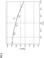
- the interpolator coefficients a, b and c can be formed by coefficient comparison from the last three samples of the data stream present at the input of the interpolator. This is exemplary in FIG. 5 which shows a diagram with a progression of encoded digital input measured values x (k-2) , x (k-1) and x (k) as well as with an interpolated profile 51.
- b x k - 1 - a ⁇ t a 2 - c t a ,
- the time interval between two digital measured values given by the sampling rate is referred to here as t a .
- the digital auxiliary measured values M H of the output output by the interpolator for the desired sampling times can now be calculated using the signal model in the form given above. For these a different sampling rate can be selected, eg an increase of the sampling rate from 4kHz to 16kHz can take place.
- FIG. 6 finally shows the progressions of a measuring signal at different points of the processing chain.
- the reference numeral 61 is in FIG. 6 the course of the analog measurement signal before sampling by the Merging Unit.
- digital input measured values 62 indicated by circles are generated and transmitted to the automation apparatus.
- a profile of encoded digital input measured values 63 (in FIG. 6 indicated by crosses) and passed to the interpolator.
- the interpolator adapts the course of encoded digital input measured values 63 with respect to the sampling rate and / or sampling instants to the desired parameters and generates on the output a profile 64 of auxiliary digital measured values.
- the digital measurement input is realized according to the invention preferably by means of a VHDL or Schematics implementation in an FPGA or an ASIC in order to prevent any delays due to a firmware implementation.
- an adaptation of the sampling rate and / or sampling times can take place for each incoming course of digital input measured values.
- multiple waveforms of digital input measurements can collide be adjusted.
- the respectively used merging units can use different sampling rates as well as different sampling times, so that the availability of the digital input measured values remains guaranteed even if an external synchronization fails due to the described formation of digital output measured values.
- time synchronization signals can also be generated by the merging units themselves. In this way, the input measured values supplied by these merging units can then be synchronized with local digital measured values even if the time synchronization signal for the synchronization of the merging units fails.
Landscapes
- Engineering & Computer Science (AREA)
- Physics & Mathematics (AREA)
- Computer Networks & Wireless Communication (AREA)
- Signal Processing (AREA)
- General Physics & Mathematics (AREA)
- Automation & Control Theory (AREA)
- Electromagnetism (AREA)
- Spectroscopy & Molecular Physics (AREA)
- Power Engineering (AREA)
- Analogue/Digital Conversion (AREA)
- Arrangements For Transmission Of Measured Signals (AREA)
- Emergency Protection Circuit Devices (AREA)
- Compression, Expansion, Code Conversion, And Decoders (AREA)
Description
Die Erfindung betrifft einen digitalen Messeingang für ein elektrisches Automatisierungsgerät, mit einer Empfangseinrichtung, die zum Empfang digitaler Eingangs-Messwerte eingerichtet ist, die durch Abtastung eines analogen Messsignals mit einer ersten Abtastrate erzeugt worden sind, und einer Signalumsetzeinrichtung, die dazu ausgebildet ist, aus den digitalen Eingangs-Messwerten digitale Ausgangs-Messwerte zu bilden und bereitzustellen, wobei die digitalen Ausgangs-Messwerte hinsichtlich ihrer Abtastrate und/oder ihres jeweiligen Abtastzeitpunktes an eine vorgegebene Abtastrate und/oder vorgegebene Abtastzeitpunkte angepasst sind. Die Erfindung betrifft außerdem ein Automatisierungsgerät mit einem solchen digitalen Messeingang und ein Verfahren zum Verarbeiten von digitalen Eingangs-Messwerten.The invention relates to a digital measuring input for an electrical automation device, having a receiving device which is adapted to receive digital input measured values, which have been generated by sampling an analog measuring signal at a first sampling rate, and a signal conversion device, which is adapted to the Digital input measurements to form and provide digital output measurements, the digital output measurements are adjusted in terms of their sampling rate and / or their respective sampling time to a predetermined sampling rate and / or predetermined sampling. The invention also relates to an automation device with such a digital measuring input and to a method for processing digital input measured values.
Elektrische Automatisierungsgeräte werden beispielsweise zur Steuerung, Überwachung und zum Schutz elektrischer Energieversorgungsnetze eingesetzt. Herkömmlicherweise sind die Automatisierungsgeräte dazu möglichst in der Nähe einer Messstelle angeordnet und nehmen mittels an der Messstelle vorgesehener Sensoren, z.B. Strom- und/oder Spannungswandler, analoge Messsignale auf, die im Automatisierungsgerät nachfolgend weiterverarbeitet werden. Ein wesentlicher Schritt bei der Weiterverarbeitung ist die Umsetzung des analogen Messsignals in digitale Abtastwerte, die den Verlauf des Analogsignals beschreiben. Unter Verwendung dieser digitalen Abtastwerte können in dem Automatisierungsgerät daraufhin Steuer-, Überwachungs- und Schutzfunktionen durchgeführt werden. Sofern das Automatisierungsgerät nicht in der Nähe aller Sensoren angeordnet werden kann, werden die analogen Messsignale über entsprechende Messleitungen an das Automatisierungsgerät herangeführt.Electrical automation devices are used, for example, for controlling, monitoring and protecting electrical energy supply networks. Conventionally, the automation devices are arranged as close as possible to a measuring point and take by means of provided at the measuring point sensors, such as current and / or voltage converter, analog measurement signals that are further processed in the automation device below. An important step in further processing is the conversion of the analog measurement signal into digital samples that describe the course of the analog signal. Using these digital samples, control, monitoring and protection functions can then be performed in the automation device. If the programmable controller can not be located in the vicinity of all sensors, the analog measuring signals will be displayed via appropriate test leads to the automation device.
Seit jüngerer Zeit bestehen Bestrebungen, die analogen Messsignale in Sensornähe mit sogenannten "Merging Units" in digitale Messsignale umzusetzen. Grund dafür sind unter anderem neue Sensor- bzw. Wandlertypen (z.B. Rogowskiwandler, optische Wandler), deren Signale sich auf analogem Wege nicht mehr über die bisher üblichen Entfernungen verteilen lassen. Hierbei weist eine solche Merging Unit einen oder mehrere analoge Messeingänge auf, deren analoge Eingangssignale mit einem Analog-Digital-Umsetzer der Merging Unit nachfolgend abgetastet und so in digitale Messwerte umgesetzt werden. Die digitalen Messwerte werden an einem Ausgang der Merging Unit üblicherweise in Form von Datentelegrammen ausgegeben und über einen Kommunikationsnetz oder einen Kommunikationsbus an ein oder mehrere übergeordnete Automatisierungsgeräte übertragen. Ein Beispiel einer solchen Merging Unit ist z.B. der Europäischen Patentanmeldung
Bei der Verwendung von über Merging Units erzeugten digitalen Messwerten entstehen jedoch neuartige Problemstellungen, die im Wesentlichen mit der zur Bildung der digitalen Messwerte in der Merging Unit verwendeten Abtastrate und/oder den Abtastzeitpunkten der jeweiligen digitalen Messwerte zusammenhängen. So kann es beispielsweise vorkommen, dass das Automatisierungsgerät intern digitale Messwerte mit einer Abtastrate benötigt, die von der in der Merging Unit verwendeten Abtastrate abweicht. Darüber hinaus besteht bei Verwendung mehrerer unterschiedlicher Messsignale die Anforderung, dass diese bezüglich ihrer Abtastrate und ihrer Abtastzeitpunkte miteinander vergleichbar sein müssen. Letzteres tritt beispielsweise bei Automatisierungsgeräten auf, die mehrere digitale Signaleingänge aufweisen, die digitale Messwerte von unterschiedlichen Merging Units erhalten. Zwar werden manche Merging Units üblicherweise über ein externes Zeitsynchronisationssignal (z.B. 1PPS-Zeitimpulse des GPS-Signals) untereinander zeitsynchronisiert und besitzen dadurch die Möglichkeit, ihre Abtastraten und Abtastzeitpunkte aufeinander abzustimmen. Diese Synchronisierung ist jedoch sehr aufwendig und kann beim Ausfall des externen Zeitsynchronisationssignals nur bedingt aufrecht erhalten werden.However, the use of digital metrics generated via merging units gives rise to novel problems that are essentially related to the sampling rate used to form the digital measurements in the merging unit and / or the sampling times of the respective digital measurements. For example, it may happen that the automation device requires internally digital readings at a sampling rate that deviates from the sampling rate used in the merging unit. In addition, when using a plurality of different measurement signals, there is a requirement that these must be comparable with respect to their sampling rate and their sampling times. The latter occurs, for example, in automation devices which have a plurality of digital signal inputs which receive digital measured values from different merging units. Although some merging units are usually time-synchronized with one another via an external time synchronization signal (eg 1PPS time pulses of the GPS signal), they have the option of to match their sample rates and sample times. However, this synchronization is very complicated and can be maintained only partially in case of failure of the external time synchronization signal.
Darüber hinaus können auch die Messwandler selbst bereits digitale Messwerte an ihren Ausgängen abgeben, die Problemstellung hierbei ist jedoch dieselbe wie bei über Merging Units erzeugten digitalen Messwerten.In addition, the transducers themselves can already deliver digital readings at their outputs, but the problem is the same as with digital metrics generated via merging units.
Ein digitaler Messeingang der eingangs genannten Art sowie ein Verfahren zum Synchronisieren mehrerer digitaler Eingangssignale in einem Automatisierungsgerät sind beispielsweise aus der deutschen Offenlegungsschrift
Dabei werden nicht im Verlauf der encodierten digitalen Messwerte vorhandene Werte mit Nullwerten aufgefüllt. Die auf diese Art nachabgetasteten encodierten digitalen Messwerte werden einem Interpolationsfilter zugeführt, der eine zum Encoder-Filter inverse Filtercharakteristik aufweist. Hierdurch kann erreicht werden, dass alle digitalen Eingangssignale nach der Verarbeitung einen gemeinsamen Abtasttakt und gemeinsame Abtastzeitpunkte aufweisen.In the process, values which are present in the encoded digital measured values are not filled with zero values. The encoded digital measured values which have been resampled in this manner are fed to an interpolation filter which has a filter characteristic which is inverse to the encoder filter. This makes it possible to ensure that all digital input signals have a common sampling clock and common sampling instants after processing.
Die Implementierung dieses bekannten Verfahrens stellt jedoch vergleichsweise hohe Anforderungen an die Rechenkapazität des Automatisierungsgerätes, beispielsweise entstehen durch die Nachabtastung mit einem relativ hohen Abtasttakt und das Auffüllen mit Nullwerten an der halben Frequenz der verwendeten Abtastrate gespiegelte Frequenzanteile der digitalen Messsignale, die erst durch aufwendige Filterung wieder entfernt werden müssen. Außerdem sehen aktuelle Normen, z.B. die Norm IEC 61850-9-2, keine Signalencodierung aufseiten einer Merging Unit vor, so dass die erzeugten digitalen Messsignale nicht ohne Weiteres mit Automatisierungsgeräten unterschiedlicher Hersteller verarbeitet werden können.The implementation of this known method, however, places comparatively high demands on the computing capacity of the automation device, for example due to the resampling with a relatively high sampling clock and the filling with zero values at half the frequency of the sampling rate used mirrored frequency components of the digital measurement signals, which must first be removed by expensive filtering again. In addition, current standards, eg the IEC 61850-9-2 standard, do not provide signal coding on the part of a merging unit so that the generated digital measuring signals can not easily be processed with automation devices from different manufacturers.
Ausgehend von einem digitalen Messeingang der eingangs genannten Art liegt der Erfindung somit die Aufgabe zugrunde, einen digitalen Messeingang anzugeben, mit dem bei effizienter Ausnutzung von Rechenkapazitäten eines Automatisierungsgerätes eine Verarbeitung von interoperabel verwendbare digitalen Eingangs-Messwerten erfolgen kann. Der Erfindung liegt zudem auch die Aufgabe zugrunde, ein entsprechendes Automatisierungsgerät mit einem digitalen Messeingang sowie ein Verfahren zum Verarbeiten von digitalen Eingangs-Messwerten anzugeben.Based on a digital measurement input of the type mentioned above, the invention is therefore based on the object to provide a digital measurement input, with the efficient use of computing capacity of an automation device processing of interoperable usable digital input measurements can be done. The invention is also based on the object of specifying a corresponding automation device with a digital measuring input and a method for processing digital input measured values.
Hinsichtlich des digitalen Messeingangs wird zur Lösung dieser Aufgabe erfindungsgemäß vorgeschlagen, einen Messeingang der eingangs genannten Art derart fortzubilden, dass die Signalumsetzeinrichtung eingangsseitig einen digitalen Encoder-Filter und ausgangsseitig einen digitalen Decoder-Filter aufweist, zwischen denen ein Interpolator vorgesehen ist, wobei der Encoder-Filter, der Interpolator und der Decoder-Filter derart aufeinander abgestimmt sind, dass durch sie die Anpassung der digitalen Eingangs-Messwerte hinsichtlich Abtastrate und/oder Abtastzeitpunkten bewirkt wird.With regard to the digital measuring input, in order to achieve this object it is proposed according to the invention to further develop a measuring input of the type mentioned above such that the signal conversion device has on the input side a digital encoder filter and on the output side a digital decoder filter between which an interpolator is provided. Filter, the interpolator and the decoder filter are matched to one another such that the adaptation of the digital input measured values in terms of sampling rate and / or sampling times is effected by them.
Durch die Ausbildung der Signalumsetzeinrichtung des digitalen Messeingangs ist es möglich, eine Anpassung der digitalen Eingangs-Messwerte hinsichtlich ihrer Abtastrate und/oder ihrer Abtastzeitpunkte ohne eine Signalencodierung in der Merging Unit durchzuführen, wodurch die interoperable Verwendbarkeit der digitalen Eingangs-Messwerte für Geräte unterschiedlicher Hersteller gewährleistet wird. Da in der Signalumsetzeinrichtung außerdem keine aufwendige Nachabtastung mit Einfügen von Nullwerten durchgeführt wird, kann die zur Anpassung benötigte Rechenleistung und die damit verbundene Rechenzeit minimiert werden. Die beiden Filter und der Interpolator der Signalumsetzeinrichtung wirken hierbei derart zusammen, dass eine gewünschte Änderung der Abtastrate und/oder Verschiebung der Abtastzeitpunkte der ausgangsseitig bereitgestellten digitalen Ausgangs-Messwerte erreicht wird. Beispielsweise kann mit dem erfindungsgemäßen digitalen Messeingang eine Abtastratenänderung von 4 kHz auf 16 kHz stattfinden, indem die benötigten zusätzlichen Abtastwerte für die digitalen Ausgangs-Messwerte durch Interpolation aus dem Verlauf der eingangsseitig vorliegenden digitalen Eingangs-Messwerte ermittelt werden. Auch kann der Interpolator auf Grundlage der bekannten digitalen Eingangs-Messwerte mit hinreichender Genauigkeit für einen bestimmten zukünftigen Zeitraum den Verlauf digitaler Ausgangs-Messwerte abschätzen, so dass er quasi als Extrapolator eingesetzt wird und anhand eines vergangenen Verlaufs digitaler Eingangs-Messwerte zukünftige digitale Ausgangs-Messwerte abschätzt.The design of the signal conversion device of the digital measuring input makes it possible to adapt the digital input measured values with regard to their sampling rate and / or their sampling times without signal coding in the merging unit, thereby ensuring the interoperable usability of the digital input measured values for devices from different manufacturers becomes. In addition, since in the signal conversion device no time-consuming resampling is performed with the insertion of zero values, the Adjustment required computing power and the associated computation time can be minimized. The two filters and the interpolator of the signal conversion device cooperate in such a way that a desired change of the sampling rate and / or shift of the sampling times of the digital output measured values provided on the output side is achieved. For example, a sampling rate change from 4 kHz to 16 kHz can take place with the digital measuring input according to the invention by determining the required additional sampling values for the digital output measured values by interpolation from the course of the digital input measured values present on the input side. Also, based on the known digital input measurements, the interpolator can estimate the course of digital output measurements for a given future time period with sufficient accuracy, so that it will be used as an extrapolator and future digital output measurements based on past history of digital input measurements estimates.
Gemäß einer vorteilhaften Ausführungsform des erfindungsgemäßen digitalen Messeingangs ist vorgesehen, dass der Interpolator zur Erzeugung von interpolierten digitalen Hilfsmesswerten unter Verwendung eines Signalmodells eingerichtet ist.According to an advantageous embodiment of the digital measuring input according to the invention, it is provided that the interpolator is set up to generate interpolated digital auxiliary measured values using a signal model.
Hierdurch kann eine möglichst genaue Abschätzung der durch Interpolation zu ermittelnden Hilfsmesswerte und damit der digitalen Ausgangs-Messwerte erfolgen. Im einfachsten Fall kann für die Interpolation ein linearer Interpolator auf Basis zweier bekannter digitaler Eingangs-Messwerte eingesetzt werden.This makes it possible to estimate as accurately as possible the auxiliary measured values to be determined by interpolation and thus the digital output measured values. In the simplest case, a linear interpolator based on two known digital input measured values can be used for the interpolation.
Als besonders vorteilhaft wird es jedoch angesehen, wenn das Signalmodell eine quadratische Funktion beschreibt.However, it is considered particularly advantageous if the signal model describes a quadratic function.
Bei Verwendung eines quadratischen Signalmodells der Form ![]()
![]()
Eine weitere vorteilhafte Ausführungsform des erfindungsgemäßen digitalen Messeingangs sieht zudem vor, dass der Encoder-Filter und der Decoder-Filter individuelle Übertragungsfunktionen aufweisen, die derart aufeinander abstimmbar sind, dass ihre gemeinsame Übertragungsfunktion eine einstellbare Verschiebung des Phasengangs der Abfolge digitaler Eingangs-Messwerte zur Erzeugung einer gewünschten zeitlichen Verschiebung der digitalen Ausgangs-Messwerte im Vergleich zu den digitalen Eingangs-Messwerten bewirkt.A further advantageous embodiment of the digital measurement input according to the invention also provides that the encoder filter and the decoder filter have individual transfer functions that are tunable to each other such that their common transfer function an adjustable shift of the phase response of the sequence of digital input measurements for generating a desired time shift of the digital output measured values compared to the digital input measured values causes.
Bei dieser Ausführungsform kann durch die bloße Auswahl der Übertragungsfunktionen der beiden Filter der Signalumsetzeinrichtung eine gewünschte zeitliche Verschiebung des Verlaufs der digitalen Ausgangs-Messwerte bezüglich des Verlaufs der digitalen Eingangs-Messwerte erreicht werden. Dies wird durch Beeinflussung des Phasengangs der digitalen Eingangs-Messwerte erreicht. Bei entsprechender Abstimmung der Übertragungsfunktionen der einzelnen Filter lässt sich nämlich eine Summenübertragungsfunktion erzielen, die den gewünschten zeitlichen Verschiebungseffekt erreicht. Hierdurch kann auf vergleichsweise einfache Art und Weise, nämlich bereits durch die Definition der jeweiligen Filterkoeffizienten, eine zeitliche Verschiebung des Verlaufs der digitalen Ausgangs-Messwerte erreicht werden, beispielsweise um Anpassungen mehrerer zeitlich verschoben eingehender digitaler Messwertverläufe aufeinander vorzunehmen.In this embodiment, by merely selecting the transfer functions of the two filters of the signal conversion device, a desired temporal shift of the course of the digital output measurement values with respect to the course of the digital input measurement values can be achieved. This is achieved by influencing the phase response of the digital input measurements. With appropriate tuning of the transfer functions of the individual filters can namely achieve a sum transfer function, which achieves the desired temporal shift effect. In this way, in a comparatively simple manner, namely already by the definition of the respective filter coefficients, a temporal shift of the course of the digital output measured values can be achieved, for example, to make adjustments to a plurality of temporally shifted incoming digital measured value progressions.
Konkret kann hinsichtlich der beiden Filter beispielsweise vorgesehen sein, dass der Encoder-Filter eine PD-Charakteristik (proportional-derivative) aufweist und der Decoder-Filter eine Tiefpasscharakteristik aufweist.Specifically, with regard to the two filters, for example, it may be provided that the encoder filter has a PD characteristic (proportional-derivative) and the decoder filter has a low-pass characteristic.
Insbesondere durch die Ausbildung des Decoder-Filters mit Tiefpasscharakteristik kann erreicht werden, dass - in den digitalen Eingangs-Messwerten bereits enthaltene oder durch die Interpolation entstehende - ungewollte hohe Frequenzanteile im Verlauf der digitalen Ausgangs-Messwerte ausreichend gedämpft werden, so dass sie auf eine nachfolgende Weiterverarbeitung der digitalen Ausgangs-Messwerte zu Steuer-, Überwachungs- und/oder Schutzzwecken keine störenden Einflüsse ausüben.In particular, due to the design of the decoder filter with a low-pass characteristic, it can be achieved that undesired high frequency components already contained in the digital input measured values or resulting from the interpolation are sufficiently attenuated in the course of the digital output measured values, so that they are limited to a subsequent one Further processing of the digital output measured values for control, monitoring and / or protection purposes do not exert any disturbing influences.
Gemäß einer weiteren vorteilhaften Ausführungsform des erfindungsgemäßen digitalen Messeingangs ist vorgesehen, dass der digitale Messeingang in Form eines Verarbeitungsbausteins mit hardwarebestimmter Programmierung, insbesondere eines ASICs oder eines FPGAs, ausgebildet ist.According to a further advantageous embodiment of the digital measuring input according to the invention, it is provided that the digital measuring input is designed in the form of a processing module with hardware-specific programming, in particular an ASIC or an FPGA.
Die Ausbildung des digitalen Messeingangs in Form eines Verarbeitungsbausteins mit hardwarebestimmter Programmierung bietet im Vergleich zu einem eine Gerätesoftware abarbeitenden Prozessorbaustein den Vorteil der höheren Verarbeitungsgeschwindigkeit, da etwaige durch die prozessorgestützte Abarbeitung der Gerätesoftware entstehende Verzögerungen ausgeschlossen werden können. Der Verarbeitungsbaustein kann somit hoch spezialisiert für die benötigte Verarbeitungsaufgabe ausgebildet werden.The formation of the digital measuring input in the form of a processing module with hardware-specific programming offers the advantage of higher processing speed in comparison to a processor module executing a device software, since any delays resulting from the processor-supported processing of the device software can be ruled out. The processing module can thus be highly specialized for the required processing task.
In diesem Zusammenhang wird es zudem als vorteilhaft angesehen, wenn der Verarbeitungsbaustein ein Speicherregister aufweist, in dem Filterkoeffizienten des Encoder-Filters und/oder des Decoder-Filters veränderbar abgespeichert sind.In this context, it is also considered advantageous if the processing module has a memory register in which filter coefficients of the encoder filter and / or the decoder filter are stored changeably.
Hierdurch kann erreicht werden, dass die Übertragungsfunktionen der beiden Filter auch nachträglich entsprechend eines gewünschten Signalgangs, insbesondere eines gewünschten Phasengangs einer gemeinsamen Summenübertragungsfunktion, angepasst werden können.In this way it can be achieved that the transfer functions of the two filters also subsequently corresponding to a desired signal path, in particular a desired phase response a common sum transfer function, can be adjusted.
Gemäß einer weiteren vorteilhaften Ausführungsform des erfindungsgemäßen digitalen Messeingangs ist zudem vorgesehen, dass die Empfangseinrichtung zum Empfang der digitalen Eingangs-Messwerte in Form von Datentelegrammen ausgebildet ist.According to a further advantageous embodiment of the digital measuring input according to the invention, it is additionally provided that the receiving device is designed to receive the digital input measured values in the form of data telegrams.
Dabei können die digitalen Eingangs-Messwerte von der Merging Unit an das Automatisierungsgerät beispielsweise als sogenannte "Sampled Measured Values" (SMV) gemäß dem bei der Kommunikation in Energieautomatisierungsanlagen mittlerweile gängigen Standard IEC 61850, speziell dem Normteil IEC 61850-9-2, übertragen werden. Durch die Verwendung einer international anerkannten Norm für die übertragen digitalen Eingangs-Messwerte wird die Interoperabilität nochmals gesteigert.In this case, the digital input measured values from the merging unit to the automation device can be transmitted, for example, as so-called "sampled measured values" (SMV) according to the standard IEC 61850, in particular the standard part IEC 61850-9-2, which is meanwhile common in communication in energy automation systems , The use of an internationally accepted standard for the transmitted digital input measurements further increases interoperability.
In diesem Zusammenhang wird es zudem als vorteilhaft angesehen, wenn die Empfangseinrichtung dazu eingerichtet ist, den die digitalen Eingangs-Messwerte enthaltenden Datentelegrammen eine Information über die erste Abtastrate zu entnehmen und diese an die Signalumsetzeinrichtung weiterzugeben.In this context, it is also considered advantageous if the receiving device is configured to extract information about the first sampling rate from the data telegrams containing the digital input measured values and to forward these to the signal conversion device.
Die Information über die Abtastrate, mit der die digitalen Eingangs-Messwerte aus dem analogen Messsignal erzeugt worden sind, wird vom Interpolator benötigt, um die empfangenen digitalen Eingangs-Messwerte zeitlich korrekt anordnen zu können. Die fragliche Information kann entweder direkt in den Datentelegrammen enthalten sein (beispielsweise kann die Information hierbei einmalig oder sporadisch oder dauernd übertagen werden), oder indirekt aus den digitalen Eingangs-Messwerten selbst entnommen werden. Beispielsweise können den digitalen Eingangs-Messwerten von der Merging Unit sogenannte Zeitstempel zugeordnet sein, die den Abtastzeitpunkt in der Merging Unit angeben und aus denen die Abtastrate berechnet werden kann. Alternativ können die digitalen Eingangs-Messwerte auch sogenannte Zählwerte bzw. "Counter Values" umfassen, die ihre zeitliche Abfolge folgend auf einen zeitlichen Synchronisationspuls (z.B. ein 1PPS-Signal) angeben. Aus dem höchsten Wert eines solchen Zählwertes kann ebenfalls auf die Abtastrate geschlossen werden (z.B. bedeutet ein höchster Wert von 3999 eine Abtastrate von 4 kHz, da der erste Wert üblicherweise den Zählwert 0 erhält).The information about the sampling rate with which the digital input measured values were generated from the analog measuring signal is required by the interpolator in order to be able to arrange the received digital input measured values correctly in time. The information in question may either be contained directly in the data telegrams (for example, the information may be transmitted once or sporadically or permanently), or may be taken indirectly from the digital input measured values themselves. For example, so-called time stamps can be assigned to the digital input measured values of the merging unit, which indicate the sampling time in the merging unit and from which the sampling rate can be calculated. Alternatively, the digital input measured values may also comprise so-called count values or "counter values" which follow their temporal sequence following a temporal sequence Specify synchronization pulse (eg a 1PPS signal). From the highest value of such a count, the sampling rate can also be deduced (eg, a highest value of 3999 means a sampling rate of 4 kHz since the first value usually gets the count 0).
Die oben genannte Aufgabe hinsichtlich der Automatisierungsgerätes wird zudem durch ein Automatisierungsgerät mit einem digitalen Messeingang nach einem der Ansprüche 1 bis 9 gelöst.The above object with regard to the automation device is also achieved by an automation device with a digital measurement input according to one of
Hinsichtlich des erfindungsgemäßen Automatisierungsgerätes gilt alles bereits zu dem erfindungsgemäßen digitalen Messeingang Gesagte, insbesondere kann das erfindungsgemäße Automatisierungsgerät einen digitalen Messeingang gemäß jeder der diesbezüglich oben beschriebenen Ausführungsformen umfassen. Auch hinsichtlich der Vorteile des erfindungsgemäßen Automatisierungsgerätes wird auf die Vorteile des erfindungsgemäßen digitalen Messeingangs verwiesen.With regard to the automation device according to the invention, everything has already been said for the digital measuring input according to the invention, in particular the automation device according to the invention may comprise a digital measuring input according to each of the embodiments described above. Also with regard to the advantages of the automation device according to the invention, reference is made to the advantages of the digital measurement input according to the invention.
Das Automatisierungsgerät kann neben dem digitalen Messeingang auch eigene lokale analoge Messeingänge besitzen. In diesem Fall wird es als vorteilhafte Ausgestaltung des erfindungsgemäßen elektrischen Automatisierungsgerätes angesehen, wenn das elektrische Automatisierungsgerät zumindest einen analogen Signaleingang aufweist, der zur Erfassung eines lokalen analogen Messsignals und zur Bildung lokaler digitaler Messwerte eingerichtet ist, und wenn die Signalumsetzeinrichtung des digitalen Messeingangs derart ausgebildet ist, zur Anpassung der digitalen Eingangs-Messwerte hinsichtlich Abtastrate und/oder Abtastzeitpunkten die Abtastrate und/oder die Abtastzeitpunkte der lokalen digitalen Messwerte als vorgegebene Abtastrate und/oder vorgegebene Abtastzeitpunkte zu verwenden.In addition to the digital measuring input, the automation device can also have its own local analogue measuring inputs. In this case, it is regarded as an advantageous embodiment of the electrical automation device according to the invention, if the electrical automation device has at least one analog signal input, which is adapted to detect a local analog measurement signal and the formation of local digital measurements, and if the signal conversion device of the digital measurement input is formed in order to use the sampling rate and / or the sampling times of the local digital measured values as a predetermined sampling rate and / or predetermined sampling times for adapting the digital input measured values with regard to sampling rate and / or sampling instants.
Bei dieser Ausführungsform weist das Automatisierungsgerät neben einem digitalen Messeingang auch zumindest einen analogen Messeingang auf, erfasst über diesen lokal ein analoges Messsignal und tastet es mit einem eigenen Analog-Digital-Umsetzer unter Bildung lokaler digitaler Messwerte ab. Hierbei können einerseits Unterschiede zwischen der lokal verwendeten Abtastrate und der Abtastrate einer vorgelagerten Merging Unit bestehen. Andererseits wird sich üblicherweise auch die durch die lokale Abtastung des analogen Messsignals entstehende zeitliche Verzögerung von derjenigen zeitlichen Verzögerung, die bei der Abtastung in der Merging Unit und dem anschließenden Übertragen der dort gebildeten digitalen Eingangs-Messwerte an das Automatisierungsgerät entsteht, unterscheiden. Üblicherweise wird die lokale Verarbeitung im Automatisierungsgerät eine kürzere zeitliche Verzögerung hervorrufen. Daher wird bei einem solchen Automatisierungsgerät mit einer gemischten analogen und digitalen Messwerterfassung eine Anpassung des Verlaufes der digitalen Eingangs-Messwerte an den Verlauf der lokalen digitalen Messwerte erfolgen müssen, um die kürzest mögliche zeitliche Verzögerung zu erreichen. Dies kann beispielsweise durch entsprechende Ausbildung der Übertragungsfunktionen der beiden Filter ermöglicht werden, die den Phasengang der eingehenden digitalen Eingangs-Messwerte derart beeinflussen, dass quasi eine zeitliche Zurückdrehung stattfindet und die im Vergleich zu den lokalen digitalen Messwerten auftretende zusätzliche Verzögerung eliminiert wird. Zudem kann auch durch den Interpolator eine dieser zeitlichen Verzögerung entsprechende zeitliche Vorausberechnung der digitalen Ausgangs-Messwerte erfolgen, um die zusätzliche zeitliche Verzögerung auszugleichen.In this embodiment, the automation device in addition to a digital measuring input and at least one analog measuring input, detected on this locally an analog Measuring signal and scans it with its own analog-to-digital converter to form local digital readings. On the one hand, there may be differences between the locally used sampling rate and the sampling rate of an upstream merging unit. On the other hand, the time delay resulting from the local sampling of the analog measuring signal will usually also differ from the time delay which arises during the sampling in the merging unit and the subsequent transfer of the digital input measured values formed there to the automation apparatus. Usually, the local processing in the programmable controller will cause a shorter time delay. Therefore, in such an automation device with a mixed analog and digital measured value acquisition, an adaptation of the course of the digital input measured values to the course of the local digital measured values must take place in order to achieve the shortest possible time delay. This can be made possible, for example, by appropriate design of the transfer functions of the two filters, which influence the phase response of the incoming digital input measured values in such a way that a quasi temporal reversal takes place and the additional delay occurring in comparison to the local digital measured values is eliminated. In addition, a temporal prediction of the digital output measured values corresponding to this time delay can also be performed by the interpolator in order to compensate for the additional time delay.
Eine weitere vorteilhafte Ausführungsform des erfindungsgemäßen Automatisierungsgerätes sieht zudem vor, dass das Automatisierungsgerät zumindest einen weiteren digitalen Messeingang aufweist, der entsprechend dem digitalen Messeingang ausgebildet sind.A further advantageous embodiment of the automation device according to the invention also provides that the automation device has at least one further digital measurement input, which are formed according to the digital measurement input.
Durch diese Ausführungsform können auch mehrere digitale Messeingänge derart aufeinander oder auf einen etwaigen lokalen analogen Messeingang abgestimmt werden, dass die jeweiligen ausgangsseitig abgegebenen digitalen Ausgangs-Messwerte hinsichtlich ihrer Abtastrate und/oder ihrer Abtastzeitpunkte aufeinander abgestimmt sind, d.h., jeder Messkanal weist eine eigene zeitliche Übertragungscharakteristik auf, die dazu ausgebildet ist, bestehende Unterschiede zwischen den einzelnen Messkanälen auszugleichen.By means of this embodiment, a plurality of digital measurement inputs can also be tuned to one another or to a possible local analog measurement input in such a way that the respective output digital output measured values are output are matched with respect to their sampling rate and / or their sampling times, ie, each measuring channel has its own temporal transmission characteristic, which is designed to compensate for existing differences between the individual measurement channels.
Alternativ kann auch vorgesehen sein, dass der erste digitale Messeingang zum Empfang und zur Verarbeitung mehrerer Verläufe digitaler Eingangs-Messwerte ausgebildet ist.Alternatively, it can also be provided that the first digital measuring input is designed to receive and to process a plurality of courses of digital input measured values.
Bei dieser Alternative werden die unterschiedlichen Verläufe digitaler Eingangs-Messwerte über einen Multiplexer der Signalanpassungseinrichtung zugeführt, die - analog wie oben zu dem digitalen Messeingang beschrieben - für jedes Signal individuell eine Anpassung hinsichtlich Abtastrate und/oder Abtastzeitpunkten vornimmt.In this alternative, the different courses of digital input measured values are fed via a multiplexer to the signal adjusting device, which - as described above for the digital measuring input - makes an individual adjustment with regard to sampling rate and / or sampling times for each signal.
Die oben genannte Aufgabe wird hinsichtlich des Verfahrens durch ein Verfahren zum Verarbeiten von digitalen Eingangs-Messwerten, die durch Abtastung eines analogen Messsignals mit einer ersten Abtastrate erzeugt worden sind, gelöst, wobei bei dem Verfahren mit einer Empfangseinrichtung eines digitalen Messeingangs eines Automatisierungsgerätes die digitalen Eingangs-Messwerte empfangen werden und mit einer Signalumsetzeinrichtung des digitalen Messeingangs, aus den digitalen Eingangs-Messwerten digitale Ausgangs-Messwerte gebildet und bereitgestellt werden, wobei die digitalen Ausgangs-Messwerte hinsichtlich ihrer Abtastrate und/oder ihres jeweiligen Abtastzeitpunktes an eine vorgegebene Abtastrate und/oder vorgegebene Abtastzeitpunkte angepasst sind.The above object is achieved in terms of the method by a method for processing digital input measurements, which have been generated by sampling an analog measurement signal at a first sampling rate, wherein in the method with a receiving device of a digital measurement input of an automation device, the digital input Measured values are received and provided with a signal conversion device of the digital measurement input, digital output measurements from the digital input measurements and provided, the digital output measurements with respect to their sampling rate and / or their respective sampling time to a predetermined sampling rate and / or predetermined Sampling times are adjusted.
Erfindungsgemäß ist vorgesehen, dass die digitalen Eingangs-Messwerte mit einem digitalen Encoder-Filter der Signalumsetzeinrichtung unter Bildung von encodierten digitalen Eingangs-Messwerten gefiltert werden, die encodierten digitalen Eingangs-Messwerte mit einem Interpolator der Signalumsetzeinrichtung unter Bildung von digitalen Hilfsmesswerten interpoliert werden, und die digitalen Hilfsmesswerte mit einem digitalen Decoder-Filter der Signalumsetzeinrichtung unter Bildung der digitalen Ausgangs-Messwerte gefiltert werden, wobei der Encoder-Filter, der Interpolator und der Decoder-Filter derart aufeinander abgestimmt sind, dass sie die Anpassung der digitalen Eingangs-Messwerte hinsichtlich Abtastrate und/oder Abtastzeitpunkten bewirken.According to the invention, the digital input measured values are filtered with a digital encoder filter of the signal conversion device to form encoded digital input measured values, the encoded digital input measured values are interpolated with an interpolator of the signal conversion device to form digital auxiliary measured values, and digital auxiliary measurements with a digital decoder filters of the signal conversion device are filtered to form the digital output measured values, wherein the encoder filter, the interpolator and the decoder filter are coordinated such that they cause the adaptation of the digital input measured values in terms of sampling rate and / or sampling times ,
Hinsichtlich des erfindungsgemäßen Verfahrens gilt darüber hinaus alles bereits zu dem erfindungsgemäßen digitalen Messeingang und zum erfindungsgemäßen Automatisierungsgerät Gesagte, so dass das erfindungsgemäße Verfahren auch zur Verarbeitung der digitalen Eingangs-Messwerte gemäß jeder der oben beschriebenen Ausführungsformen des erfindungsgemäßen digitalen Messeingangs und des erfindungsgemäßen Automatisierungsgerätes geeignet ist. Auch hinsichtlich der Vorteile des erfindungsgemäßen Verfahrens wird auf die Vorteile des erfindungsgemäßen digitalen Messeingangs und des erfindungsgemäßen Automatisierungsgerätes verwiesen.With regard to the method according to the invention, moreover, everything already applies to the digital measuring input according to the invention and to the automation device according to the invention, so that the method according to the invention is also suitable for processing the digital input measured values according to each of the above-described embodiments of the digital measuring input according to the invention and of the automation device according to the invention. Also with regard to the advantages of the method according to the invention, reference is made to the advantages of the digital measuring input according to the invention and the automation device according to the invention.
Eine vorteilhafte Ausführungsform des erfindungsgemäßen Verfahren sieht zudem vor, dass eine aus einer Verknüpfung der individuellen Übertragungsfunktionen des Encoder-Filters und des Decoder-Filters resultierende gemeinsame Übertragungsfunktion eine einstellbare Verschiebung des Phasengangs der Abfolge der digitalen Eingangs-Messwerte zur Erzeugung einer gewünschten zeitlichen Verschiebung der digitalen Ausgangs-Messwerte im Vergleich zu den digitalen Eingangs-Messwerten bewirkt.An advantageous embodiment of the method according to the invention also provides that a common transfer function resulting from a combination of the individual transfer functions of the encoder filter and the decoder filter, an adjustable shift of the phase response of the sequence of digital input measurements to produce a desired time shift of the digital Output measured values compared to the digital input measured values causes.
Bei dieser Ausführungsform kann durch die bloße Auswahl der Übertragungsfunktionen der beiden Filter der Signalumsetzeinrichtung eine gewünschte zeitliche Verschiebung des Verlaufs der digitalen Ausgangs-Messwerte bezüglich des Verlaufs der digitalen Eingangs-Messwerte erreicht werden.In this embodiment, by merely selecting the transfer functions of the two filters of the signal conversion device, a desired temporal shift of the course of the digital output measurement values with respect to the course of the digital input measurement values can be achieved.
Die Erfindung wird nachfolgend anhand eines Ausführungsbeispiels näher erläutert. Die spezifische Ausgestaltung des Ausführungsbeispiels ist für die allgemeine Ausgestaltung des erfindungsgemäßen digitalen Messeingangs, des erfindungsgemäßen Automatisierungsgerätes und des erfindungsgemäßen Verfahrens in keiner Weise einschränkend zu verstehen; vielmehr können einzelne Ausgestaltungsmerkmale des Ausführungsbeispiels in beliebiger Weise frei untereinander und mit den voranstehend beschriebenen Merkmalen kombiniert werden.The invention will be explained in more detail with reference to an embodiment. The specific embodiment of the embodiment is for the general embodiment of inventive digital measuring input, the automation device according to the invention and the method according to the invention in no way limiting to understand; Rather, individual design features of the embodiment can be freely combined with each other and with the features described above in any manner.
Es zeigen
Figur 1- eine schematische Darstellung einer Energieautomatisierungsanlage mit an ein elektrisches Automatisierungsgerät angeschlossenen Merging Units;
Figur 2- eine schematische Darstellung eines Ausführungsbeispiels eines digitalen Messeingangs mit einer Signalumsetzeinrichtung;
Figur 3- ein Diagramm mit Verläufen eines analogen Signals, einer Abfolge von mit einer Merging Unit erzeugten digitalen Eingangs-Messwerten und einer Abfolge von mit einem Automatisierungsgerät erfassten lokalen digitalen Messwerten;
Figur 4- ein Diagramm mit einem vergrößerten Ausschnitt aus dem Diagramm in
Figur 3 - Figur 5
- ein Diagramm zur Erläuterung der Vorgehensweise bei der Interpolation auf Basis der digitalen Eingangs-Messwerte; und
Figur 6- ein Diagramm mit verschiedenen Signalverläufen zur Erläuterung der Datenverarbeitung in einer Signalumsetzeinrichtung.
- FIG. 1
- a schematic representation of an energy automation system connected to an electrical automation device merging units;
- FIG. 2
- a schematic representation of an embodiment of a digital measuring input with a signal conversion device;
- FIG. 3
- a diagram with traces of an analog signal, a sequence of generated with a merging unit digital input measurements and a sequence of detected with an automation device local digital measurements;
- FIG. 4
- a diagram with an enlarged detail from the diagram in
FIG. 3 ; - FIG. 5
- a diagram for explaining the procedure in the interpolation on the basis of the digital input measured values; and
- FIG. 6
- a diagram with various signal waveforms for explaining the data processing in a Signalumetzeinrichtung.
An Messstellen 13a-b des Energieversorgungsnetzes werden mittels geeigneter Wandler analoge Messsignale erfasst, die beispielsweise an den Messstellen 13a-b vorherrschende Ströme und/oder Spannungen angeben. Konkret werden beispielsweise an den Messstellen 13a und 13b analoge Stromsignale i1, i2, i3 und i4 sowie analoge Spannungssignale u1 und u2 erfasst und den Merging Units 12a-b zugeführt. Nachfolgend wird die Signalverarbeitung beispielhaft anhand der Merging Unit 12b beschrieben, die Beschreibung ist entsprechend auch auf die Merging Unit 12a anwendbar. Die Merging Unit 12b wandelt die empfangenen analogen Messsignale, hier konkret die Signale i3, i4, u2 durch Abtastung mit einem Analog-Digital-Umsetzer 14 in digitale Eingangs-Messwerte ME um. Dabei kann der Analog-Digital-Umsetzer 14 zur Abtastung beispielsweise einen Abtasttakt von 4kHz verwenden. Der Abtasttakt kann durch ein externes Zeitsynchronisationssignal, z.B. einen 1PPS-Impuls (1PPS=1 Pulse per Second), synchronisiert oder freilaufend sein. Die Merging Unit 12b bildet mit den digitalen Eingangs-Messwerten ME Datentelegramme T und gibt diese ausgangsseitig über eine Datenschnittstelle 15 an einen auch als Prozessbus bezeichneten Datenkommunikationsbus 16 zur Übertragung von prozessbezogenen Messwerten, Ereignisdaten und Befehlen ab. Dabei können die die digitalen Eingangs-Messwerte ME enthaltenden Datentelegramme T beispielsweise als sogenannte "Sampled Measured Values" (SMV) gemäß dem Standard IEC 61850-9-2 ausgebildet sein und über einen Ethernet basierten Datenkommunikationsbus 16 übertragen werden.At measuring
Die Datentelegramme T werden dem Automatisierungsgerät 11 zugeführt. Dieses weist ein Prozessbusmodul 17a auf, mit dem die Telegramme T empfangen und daraus die darin enthaltenen digitalen Eingangs-Messwerte ME extrahiert werden. Das Prozessbusmodul 17a weist zum Empfang der Datentelegramme T mindestens eine physikalische Prozessbusschnittstelle, z.B. eine Ethernetschnittstelle 18, auf. Bei dem Ausführungsbeispiel gemäß
Das Automatisierungsgerät 11 weist neben dem Prozessbusmodul 17a auch ein Prozessormodul 17b und ein Analogeingangsmodul 17c auf. Die einzelnen Module 17a-17c sind über einen internen Kommunikationsbus 19 miteinander verbunden, über den interne Daten ausgetauscht werden und auch eine Zeitsynchronisation der einzelnen Module 17a-17c durchgeführt wird, so dass alle Module 17a-17c des Automatisierungsgerätes 11 dieselbe Systemzeit verwenden.In addition to the
Das Analogeingangsmodul 17c ist direkt mit an einer weiteren Messstelle 13c des elektrischen Energieversorgungsnetzes angeordneten Messwandlern verbunden und nimmt von diesen beispielsweise ein analoges Stromsignal i5 und ein analoges Spannungssignal u3 auf. Diese lokal erfassten analogen Messsignale werden einem Analog-Digital-Umsetzer des Analogeingangsmoduls 17c zugeführt und dort in lokale digitale Messwerte Mlok umgesetzt. Dazu wird beispielsweise ein Abtasttakt von 16kHz verwendet, der über die Systemzeit gesteuert und durch ein externes Zeitsynchronisationssignal (z.B. 1PPS-Impuls) mit anderen Signalen genau in Vergleich gesetzt werden kann.The
Die lokalen digitalen Messwerte Mlok werden ebenso wie die über von dem Prozessbusmodul 17a bereitgestellten digitalen Ausgangs-Messwerte MA von dem Prozessormodul 17b zur Ausführung von Steuer-, Überwachungs- und/oder Schutzfunktionen für das elektrische Energieversorgungsnetz verwendet. Handelt es sich bei dem Automatisierungsgerät 11 beispielsweise um ein elektrisches Schutzgerät, so werden von dem Prozessormodul 17b unter anderem Schutzalgorithmen, wie z.B. ein Distanzschutzalgorithmus oder ein Differentialschutzalgorithmus, durchgeführt, um Fehler in dem elektrischen Energieversorgungsnetz erkennen und abschalten zu können.The local digital measurements M lok as well as the digital output measurements M A provided by the
Zur Durchführung der Funktionen benötigt das Prozessormodul 17b miteinander vergleichbare Messwerte, d.h. die vom Prozessbusmodul 17a empfangenen digitalen Eingangs-Messwerte ME müssen hinsichtlich ihrer Abtastrate und/oder ihres Abtastzeitpunktes an die aus den lokal erfassten analogen Signalen gebildeten lokalen digitalen Messwerten Mlok angepasst werden. Im vorliegenden Fall sollen beispielhaft sowohl die Abtastrate als auch die Abtastzeitpunkte der digitalen Eingangs-Messwerte ME und der lokalen digitalen Messwerte Mlok voneinander abweichen, da einerseits in den Merging Units 12a-b eine andere Abtastrate als im Automatisierungsgerät 11 verwendet werde (4 kHz anstelle von 16 kHz) und andererseits die Abtastzeitpunkte der einzelnen Messwertverläufe nicht miteinander synchronisiert seien. Daher müssen die über das Prozessbusmodul 17a empfangenen digitalen Eingangs-Messwerte ME vor ihrer Weitergabe an das Prozessormodul 17b mittels eines digitalen Messeingangs 20 unter Bildung der digitalen Ausgangs-Messwerte MA hinsichtlich ihrer Abtastrate und ihrer Abtastzeitpunkte an die lokalen digitalen Messwerte Mlok angepasst werden.In order to perform the functions, the
In
Die Funktionsweise des digitalen Messeingangs 20 wird nachfolgend anhand von
Neben den digitalen Eingangs-Messwerten ME selbst entnimmt die Empfangseinrichtung 21 auch eine Information I über die Abtastrate, mit der die digitalen Eingangs-Messwerte ME in der Merging Unit 12a-b erzeugt worden sind und über den Abtastzeitpunkt Z des jeweiligen digitalen Eingangs-Messwerts ME aus den Datentelegrammen T. Beispielsweise kann die Information I über die verwendete Abtastrate direkt in einem, in einigen oder in allen Datentelegrammen T enthalten sein. Alternativ kann die Empfangseinrichtung 21 die Information auch wie oben bereits erläutert indirekt über den digitalen Eingangs-Messwerten ME zugeordnete Zeitstempel oder Zählwerte entnehmen. Die Information Z über den Abtastzeitpunkt kann beispielsweise aus einem Zeitstempel oder einem Zählwert abgeleitet werden.In addition to the digital input measured values M E itself, the receiving
Die Informationen I und Z über die Abtastrate und den Abtastzeitpunkt der digitalen Eingangs-Messwerte ME werden von der Empfangseinrichtung 21 einer Zeitsteuereinrichtung 22 des digitalen Messeingangs 20 übergeben. Bei nur indirekt ermittelbaren Informationen I und/oder Z kann alternativ die Empfangseinrichtung 21 auch die Zeitstempel oder die Zählwerte der digitalen Eingangs-Messwerte ME direkt an die Zeitsteuereinrichtung 22 übergeben, die daraufhin selbst die Informationen I und oder Z über die Abtastrate I bzw. die jeweiligen Abtastzeitpunkte ermittelt.The information I and Z on the sampling rate and the sampling time of the digital input measured values M E are transmitted by the receiving
Der Zeitsteuereinrichtung 22 wird darüber hinaus auch ein die Systemzeit angebende internes Zeitsignal TSync des Automatisierungsgerätes 11 zugeführt. Anhand der Informationen über die Abtastzeitpunkte der digitalen Messwerte einerseits und die Systemzeit andererseits kann bei bekannter zeitlicher Verzögerung durch die Abtastung in der Merging Unit 12a-b und die Übertragung zwischen Merging Unit 12a-b und Automatisierungsgerät 11 einerseits ein zeitlicher Versatz zwischen der Systemzeit und den Abtastzeitpunkten der digitalen Eingangs-Messwerte ME ermittelt werden und andererseits ein Bezug zwischen den auf der Zeitbasis der jeweiligen Merging Unit 12a-b beruhenden digitalen Eingangs-Messwerte ME und den in der Signalumsetzeinrichtung 26 zu bildenden, auf der Systemzeit des Automatisierungsgerätes 11 beruhenden digitalen Ausgangs-Messwerten MA hergestellt werden.In addition, the
Die aus den Datentelegrammen T entnommenen digitalen Eingangs-Messwerte ME werden von der Empfangseinrichtung 21 an die Signalumsetzeinrichtung 26 übergeben, die eingangsseitig einen digitalen Encoder-Filter 23 aufweist. Der Encoder-Filter kann beispielsweise eine Übertagungsfunktion mit einer PD-Charakteristik aufweisen. Die digitalen Eingangs-Messwerte ME werden in dem digitalen Encoder-Filter 23 unter Bildung von encodierten digitalen Eingangs-Messwerten ME * gefiltert. Nach der Filterung mit dem Encoder-Filter 23 werden die encodierten digitalen Messwerte ME * einem Interpolator 24 zugeführt, der unter Verwendung eines Signalmodells auf Basis der encodierten digitalen Messwerte ME * unter Bildung von digitalen Hilfsmesswerten MH eine Interpolation durchführt und dabei die encodierten digitalen Eingangs-Messwerte ME * hinsichtlich ihrer Abtastrate und ihres jeweiligen Abtastzeitpunktes an die geforderte Abtastrate und die geforderten Abtastzeitpunkte anpasst. Hierzu nutzt der Interpolator 24 die von der Zeitsteuereinrichtung 22 bereitgestellten Informationen über die Abtastrate bzw. die Abtastzeitpunkte der digitalen Messwerte einerseits und die Systemzeit andererseits. Der Interpolator 24 berechnet beispielsweise anhand der encodierten digitalen Eingangs-Messwerte ME * durch Interpolation digitale Hilfsmesswerte MH mit einer Abtastrate von 16kHz zu durch die Systemzeit vorgegebenen Abtastzeitpunkten. Die digitalen Hilfsmesswerte MH werden vom Interpolator 24 ausgangsseitig an einen Decoder-Filter 25 weitergegeben, der beispielsweise eine Tiefpasscharakteristik aufweist. Der Decoder-Filter 25 übernimmt hierbei unter anderem die Funktion einer Bandbegrenzung, indem nicht gewünschte hohe Frequenzanteile gedämpft werden. Ausgangsseitig gibt der Decoder-Filter 25 die digitalen Ausgangs-Messwerte MA ab, die hinsichtlich ihrer Abtastrate und ihrer Abtastzeitpunkte an die zur Weiterverarbeitung in der Prozessorbaugruppe 17b (vgl.
Die Übertragungsfunktionen des Encoder-Filters 23 und des Decoder-Filters 25 können vorteilhafterweise derart aufeinander abgestimmt sein, dass die sich ergebende Summenübertragungsfunktion durch Beeinflussung des Phasengangs der digitalen Eingangs-Messwerte ME eine Anpassung der zeitlichen Verzögerung der gebildeten digitalen Ausgangs-Messwerte MA an die lokalen digitalen Messwerte Mlok bewirkt. Dies ist in
Hierzu ist in
Die Verläufe 31 und 32 sind im Vergleich zum analogen Messsignal 31 zeitlich verschoben; die jeweilige zeitliche Verschiebung resultiert aus der Verarbeitungszeit bei der Abtastung und ggf. aus der Übertragungszeit. Man erkennt einerseits, dass die lokalen digitalen Messwerte Mlok mit einer deutlich höheren Abtastrate erzeugt worden sind (die Ellipsen liegen dichter beieinander) als die digitalen Eingangs-Messwerte ME der Merging Unit. Andererseits wird auch ersichtlich, dass durch die Abtastung in der Merging Unit und die anschließende Übertragung der digitalen Eingangs-Messwerte ME der Verlauf 32 eine deutlich größere zeitliche Verschiebung zum analogen Messsignal 30 aufweist als der Verlauf 31 der lokalen digitalen Messwerte Mlok. Dies ist in
Um die beiden Verläufe 31 und 32 miteinander vergleichen zu können, müssen durch die Signalumsetzeinrichtung 26 (vgl.
Durch den Interpolator werden hierzu einerseits die Abtastrate der digitalen Eingangs-Messwerte ME entsprechend erhöht und andererseits deren Abtastzeitpunkte mit denen der lokalen digitalen Messwerte Mlok synchronisiert. Durch das Zusammenwirken des Encoder-Filters und des Decoder-Filters wird der Phasengang der digitalen Eingangs-Messwerte ME entsprechend beeinflusst, um die Differenz tD,MU - tD,lok der beiden zeitlichen Verzögerungen der Verläufe 31 und 32 auszugleichen. Damit wird der Verlauf 32 der digitalen Eingangs-Messwerte ME quasi mit dem Verlauf 31 der lokalen digitalen Messwerte Mlok in Überdeckung gebracht.For this purpose, on the one hand, the sampling rate of the digital input measured values M E is correspondingly increased by the interpolator and, on the other hand, its sampling times are synchronized with those of the local digital measured values M lok . The interaction of the encoder filter and the decoder filter is the Phase response of the digital input measured values M E influenced accordingly to compensate for the difference t D, MU - t D, lok of the two time delays of the
Mittels des Encoder-Filters werden zusammengefasst also die von der Merging Unit empfangenen digitalen Eingangs-Messwerte ME ohne vorherige Abtastratenkonvertierung gefiltert. Aus den entstehenden encodierten digitalen Eingangs-Messwerten ME * werden mittels des Interpolators digitale Hilfsmesswerte MH zu den gewünschten neuen Abtastzeitpunkten mit der gewünschten neuen Abtastrate aus den encodierten digitalen Messwerten ME * gebildet. Der aus den digitalen Hilfsmesswerten MH bestehende neue Abtastwertestrom wird mittels des Decoder-Filters in die digitalen Ausgangsmesswerte MA der neuen Abtastrate umgewandelt.By means of the encoder filter, therefore, the digital input measured values M E received by the merging unit are filtered without prior sample rate conversion. * Auxiliary digital measurement values M H to the desired new sampling time points with the desired new sampling rate of the encoded digital measurement values M * E to be formed by means of the interpolator from the resulting encoded input digital measured values M e. The new sample current consisting of the digital auxiliary measured values M H is converted into the digital output measured values M A of the new sampling rate by means of the decoder filter.
Wenn durch die Signalverarbeitung in der Signalumsetzeinrichtung keine zeitliche Verschiebung gewünscht wird, bildet die Faltung der Übertragungsfunktionen des Encoder-Filters und des Decoder-Filters im Zeitbereich den Wert 1. Das ist immer dann möglich, wenn die Abtastraten vor und nach der Interpolation gleich sind oder nach der Interpolation eine höhere Abtastrate verwendet wird. Weiterhin kann durch Wahl einer Summenübertragungsfunktion mit vorgegebener frequenzabhängiger oder konstanter Gruppenlaufzeit für die gefalteten Übertragungsfunktionen des Encoder-Filters und des Decoder-Filters eine frequenzabhängige zeitliche Verschiebung so eingestellt werden, dass die entstehende Gruppenlaufzeit der digitalen Eingangs-Messwerte ME an die Gruppenlaufzeit der lokalen digitalen Messwerte Mlok exakt angepasst wird. Auf diese Weise kann quasi eine Anpassung der Übertragungscharakteristik der von einer Merging Unit empfangenen digitalen Eingangs-Messwerte ME an die Übertragungscharakteristik der lokalen digitalen Messwerte Mlok erfolgen. Ist die Gruppenlaufzeit der digitalen Eingangs-Messwerte ME von der Merging Unit bereits größer als die Gruppenlaufzeit der lokalen digitalen Messwerte Mlok, kann die Gruppenlaufzeit der Eingangs-Messwerte ME auch auf ein ganzzahliges Vielfaches der Gruppenlaufzeit der lokalen digitalen Messwerte Mlok eingestellt werden. Ein Verzögern des Wertestroms der lokalen digitalen Messwerte um die Anzahl Abtastwerte, die der Differenz der beiden Gruppenlaufzeiten entspricht, liefert dann zueinander synchrone Werteströme.If no time shift is desired by the signal processing in the signal conversion device, the convolution of the transfer functions of the encoder filter and the decoder filter in the time domain forms the
Die Interpolation erfolgt auf der Basis eines Signalmodells, so dass im interpolierten Verlauf der digitalen Hilfsmesswerte MH Interpolationsfehler nur oberhalb der halben ursprünglichen Abtastfrequenz erzeugt und diese Interpolationsfehler durch das Decoder-Filter so weit gedämpft werden, dass die Interpolationsfehler in dem am Ausgang des Decoder-Filters bereitstehenden Verlauf von digitalen Ausgangs-Messwerten MA eine Amplitude unterhalb der geforderten Signalauflösung aufweisen.The interpolation takes place on the basis of a signal model, so that in the interpolated course of the auxiliary digital measured values M H interpolation errors are generated only above half the original sampling frequency and these interpolation errors are attenuated by the decoder filter so far that the interpolation errors in that at the output of the decoder. Filter available history of digital output measurements M A have an amplitude below the required signal resolution.
Hinsichtlich der Auslegung der Filter können beispielsweise folgende Überlegungen angestellt werden:
Das beschriebene Verfahren kann z.B. durch die Verwendung von digitalen IIR-Filtern für den Encoder-Filter und den Decoder-Filter realisiert werden. Wenn durch die beiden Filter insgesamt keine zeitliche Verschiebung des Verlaufes der digitalen Eingangs-Messwerte erfolgen soll, ist die folgende Summenübertragungsfunktion im Frequenzbereich zu verwenden: ![]()
- G(jω) für die Summenübertragungsfunktion im Frequenzbereich,
- GEnc(jω) für die Übertragungsfunktion des Encoder-Filters,
- GDec(jω) für die Übertragungsfunktion des Decoder-Filters,
- ω für die Kreisfrequenz und
- j für die imaginäre Zahl.
The method described can be realized, for example, by the use of digital IIR filters for the encoder filter and the decoder filter. If, as a result of the two filters, there is no overall time shift of the course of the digital input measured values, the following sum transfer function must be used in the frequency domain:
- G (jω) for the sum transfer function in the frequency domain,
- G Enc (jω) for the transfer function of the encoder filter,
- G Dec (jω) for the transfer function of the decoder filter,
- ω for the angular frequency and
- j for the imaginary number.
Für die Reihenschaltung des Encoder-Filters und des Decoder-Filters wird in diesem Fall also eine Summenübertragungsfunktion angestrebt, die das Signal nicht verändert. Das ist immer dann möglich, wenn die Abtastraten vor und nach der Interpolation gleich sind oder nach der Interpolation eine höhere Abtastrate verwendet wird. Weiterhin kann durch Wahl einer Summenübertragungsfunktion mit vorgegebener frequenzabhängiger oder konstanter Gruppenlaufzeit für die gefalteten Übertragungsfunktionen des Encoder-Filters und des Decoder-Filters eine frequenzabhängige zeitliche Verschiebung so eingestellt werden, dass die entstehende Gruppenlaufzeit der digitalen Eingangs-Messwerte an die Gruppenlaufzeit der lokalen digitalen Messwerte exakt angepasst wird. Auf diese Weise kann eine Anpassung der Übertragungscharakteristik der von der Merging Unit empfangenen digitalen Eingangs-Messwerte an die Übertragungscharakteristik der lokalen digitalen Messwerte erfolgen.For the series connection of the encoder filter and the decoder filter in this case, therefore, a total transfer function is sought, which does not change the signal. This is always possible if the sampling rates are the same before and after the interpolation or if a higher sampling rate is used after the interpolation. Furthermore, by selecting a sum transfer function with a predetermined frequency-dependent or constant group delay for the folded transfer functions of the encoder filter and the decoder filter, a frequency-dependent time shift can be set so that the resulting group delay of the digital input measured values to the group delay of the local digital measured values exactly is adjusted. In this way, the transmission characteristic of the digital input measured values received by the merging unit can be adapted to the transmission characteristic of the local digital measured values.
Im Falle einer im Vergleich zur ursprünglichen Abtastrate niedrigeren Abtastrate der digitalen Ausgangs-Messwerte muss eine Tiefpass-Charakteristik für die Summenübertragungsfunktion beider Filter mit den entsprechend gewünschten Anti-Aliasing-Eigenschaften gewählt werden.In the case of a lower sampling rate of the digital output measurements compared to the original sampling rate, a low-pass characteristic must be selected for the sum transmission function of both filters with the corresponding desired anti-aliasing properties.
Beispielsweise kann für den Encoder-Filter eine Übertragungsfunktion 
- To für eine obere Zeitkonstante des Filters,
- Tu für eine untere Zeitkonstante des Filters und
- n für die Filterordnung.
- T o for an upper time constant of the filter,
- T u for a lower time constant of the filter and
- n for the filter order.
Für den Decoder-Filter kann entsprechend die Übertragungsfunktion 
![]()
- A und B für die Filterkoeffizienten,
- k für den Zählwert des jeweiligen Messwertes,
- x für die am Eingang des Filters vorliegenden Messwerte und
- y für die ausgangsseitig am Filter abgegebenen Messwerte.
- A and B for the filter coefficients,
- k for the count value of the respective measured value,
- x for the measured values at the input of the filter and
- y for the measured values delivered to the filter on the output side.
Durch die individuelle Vorgabe der Koeffizienten A und B für die einzelnen Filter kann die Summenübertragungsfunktion insgesamt in der gewünschten Weise beeinflusst werden. Sofern der digitale Messeingang als ASIC oder FPGA ausgebildet ist, können die Filterkoeffizienten z.B. in einem Speicherregister des fraglichen Bausteins veränderbar vorgegeben werden.By individually specifying the coefficients A and B for the individual filters, the sum transfer function can be influenced overall in the desired manner. If the digital measuring input is designed as an ASIC or FPGA, the filter coefficients can be used, for example. be variably set in a memory register of the block in question.
Für die Filter können beispielsweise folgende Parameter verwendet werden: ![]()
![]()
Für den Interpolator kann beispielsweise ein Signalmodell in Form einer quadratischen Funktion verwendet werden: ![]()
![]()
Die Interpolator-Koeffizienten a, b und c können mittels Koeffizientenvergleich aus den letzten drei Abtastwerten des am Eingang des Interpolators vorliegenden Datenstroms gebildet werden. Dies ist beispielhaft in 
Als ta wird hier der durch die Abtastrate vorgegebene zeitliche Abstand zwischen zwei digitalen Messwerten bezeichnet. Der Bezugspunkt für t=0 der berechneten Koeffizienten des Signalmodells ist hier x(k-2). Aus den am Eingang des Interpolators vorliegenden encodierten digitalen Eingangs-Messwerten ME * können nun unter Nutzung des Signalmodells in der oben angegeben Form die digitalen Hilfsmesswerte MH des ausgangsseitig vom Interpolator abgegebenen Verlaufs für die gewünschten Abtastzeitpunkte berechnet werden. Für diese kann auch eine andere Abtastrate gewählt werden, z.B. kann eine Erhöhung der Abtastrate von 4kHz auf 16kHz stattfinden.The time interval between two digital measured values given by the sampling rate is referred to here as t a . The reference point for t = 0 of the calculated coefficients of the signal model is x (k-2) . From the encoded digital input measured values M E * present at the input of the interpolator, the digital auxiliary measured values M H of the output output by the interpolator for the desired sampling times can now be calculated using the signal model in the form given above. For these a different sampling rate can be selected, eg an increase of the sampling rate from 4kHz to 16kHz can take place.
Durch die Interpolation werden im Verlauf der ausgangsseitig vorliegenden Hilfsmesswerte MH zusätzliche Spektralanteile erzeugt, die im Originalsignal nicht enthalten waren. Diese Spektralanteile werden anschließend durch die Filterung mit dem Decoder-Filter soweit unterdrückt, dass die durch die Interpolation induzierten Harmonischen vernachlässigt werden können.As a result of the interpolation, additional spectral components which were not contained in the original signal are generated in the course of the auxiliary measured values M H present on the output side. These spectral components are then suppressed by the filtering with the decoder filter so far that by the interpolation induced harmonics can be neglected.
Der digitale Messeingang wird erfindungsgemäß vorzugsweise mittels einer VHDL- oder Schematics-Implementierung in einem FPGA oder einem ASIC realisiert, um etwaige Verzögerungen durch eine Firmware-Implementierung zu verhindern.The digital measurement input is realized according to the invention preferably by means of a VHDL or Schematics implementation in an FPGA or an ASIC in order to prevent any delays due to a firmware implementation.
Mit dem beschriebenen digitalen Messeingang eines Automatisierungsgerätes sowie dem beschriebenen Verfahren zur Verarbeitung digitaler Eingangs-Messwerte kann einerseits für jeden eingehenden Verlauf digitaler Eingangs-Messwerte eine Anpassung von Abtastrate und/oder Abtastzeitpunkten stattfinden. Darüber hinaus ist es wie erläutert möglich, die digitalen Eingangs-Messwerte an vom Automatisierungsgerät direkt abgetastete lokale digitale Messwerte anzupassen. Außerdem können mehrere Verläufe digitaler Eingangs-Messwerte aufeinander angepasst werden. Dabei können die jeweils verwendeten Merging Units unterschiedliche Abtastraten sowie unterschiedliche Abtastzeitpunkte verwenden, so dass auch beim Ausfall einer externen Synchronisierung durch die beschriebene Bildung digitaler Ausgangs-Messwerte die Verwendbarkeit der digitalen Eingangs-Messwerte gewährleistet bleibt.On the one hand, with the described digital measuring input of an automation device and the described method for processing digital input measured values, an adaptation of the sampling rate and / or sampling times can take place for each incoming course of digital input measured values. In addition, as explained, it is possible to adapt the digital input measured values to local digital measured values directly sampled by the automation device. In addition, multiple waveforms of digital input measurements can collide be adjusted. The respectively used merging units can use different sampling rates as well as different sampling times, so that the availability of the digital input measured values remains guaranteed even if an external synchronization fails due to the described formation of digital output measured values.
Auch ist es im Rahmen der Erfindung denkbar, dass mehrere externe Zeitsynchronisiersignale für jeweils eine Merging Unit oder eine Gruppe von Merging Units verwendet werden. Diese Zeitsynchronisationssignale können von den Merging Units auch selbst generiert werden. Auf diese Weise können dann die von diesen Merging Units gelieferten Eingangs-Messwerte auch dann noch mit lokalen digitalen Messwerten synchronisiert werden, wenn das Zeitsynchronisationssignal zur Synchronisation der Merging Units ausfällt.It is also conceivable within the scope of the invention for a plurality of external time synchronization signals to be used in each case for one merging unit or one group of merging units. These time synchronization signals can also be generated by the merging units themselves. In this way, the input measured values supplied by these merging units can then be synchronized with local digital measured values even if the time synchronization signal for the synchronization of the merging units fails.
Claims (15)
- Digital measurement input (20) for an electric automation device (11), with- a receiving device (21) which is configured to receive digital input measurement values which have been generated by sampling an analog measurement signal at a first sampling rate; and- a signal conversion device (26) which is designed to form and provide digital output measurement values from the digital input measurement values, wherein the sampling rate and/or respective sampling times of the digital output measurement values is/are adapted to a specified sampling rate and/or specified sampling times, wherein- the signal conversion device (26) has a digital encoder filter (23) on the input side and a decoder filter (25) on the output side, between which an interpolator (24) is provided, characterized in that- the encoder filter (23), the interpolator (24) and the decoder filter (25) are matched to one another so that the adaptation of the sampling rate and/or sampling times of the digital input measurement values is effected by them.
- Digital measurement input (20) according to Claim 1, characterized in that- the interpolator (24) is configured to generate interpolated digital auxiliary measurement values using a signal model.
- Digital measurement input (20) according to Claim 2, characterized in that- the signal model describes a quadratic function.
- Digital measurement input (20) according to one of the preceding claims,
characterized in that- the encoder filter (23) and the decoder filter (25) have individual transmission functions which can be matched to one another so that their common transmission function effects an adjustable shift of the phase response of the sequence of digital input measurement values in order to generate a required temporal shift of the digital output measurement values compared to the digital input measurement values. - Digital measurement input (20) according to one of the preceding claims,
characterized in that- the encoder filter (23) has a PD characteristic and the decoder filter (25) has a low-pass characteristic. - Digital measurement input (20) according to one of the preceding claims,
characterized in that- the digital measurement input (20) is designed in the form of a processing module with hardware-defined programming, in particular an ASIC or an FPGA. - Digital measurement input (20) according to Claim 6,
characterized in that- the processing module has a memory register in which filter coefficients of the encoder filter and/or the decoder filter are modifiably stored. - Digital measurement input (20) according to one of the preceding claims,
characterized in that- the receiving device (21) is designed to receive the digital input measurement values in the form of data messages. - Digital measurement input (20) according to Claim 8,
characterized in that- the receiving device (21) is configured to extract information relating to the first sampling rate from the data messages
containing the digital input measurement values and forward said information to the signal conversion device (26). - Electric automation device (11) with a digital measurement input (20) according to one of the preceding Claims 1 to 9.
- Electric automation device (11) according to Claim 10, characterized in that- the electric automation device (11) has at least one analog signal input which is configured to capture a local analog measurement signal and to form local digital measurement values; and- the signal conversion device (26) of the digital measurement input (20) is designed to use the sampling rate and/or the sampling times of the local digital measurement values as the specified sampling rate and/or specified sampling times in order to adapt the sampling rate and/or sampling times of the digital input measurement values.
- Electric automation device (11) according to one of Claims 10 and 11,
characterized in that- the automation device (11) has at least one further digital measurement input which is designed according to the digital measurement input (20). - Electric automation device (11) according to one of Claims 10 and 11,
characterized in that- the digital measurement input (20) is designed to receive and process a plurality of sequences of digital input measurement values. - Method for processing digital input measurement values which have been generated by sampling an analog measurement signal at a first sampling rate, wherein, in the method:- the digital input measurement values are received with a receiving device (21) of a digital measurement input (20) of an automation device (11); and- digital output measurement values are formed and provided with a signal conversion device (26) of the digital measurement input (20) from the digital input measurement values, wherein the sampling rate and/or respective sampling times of the digital output measurement values are adapted to a specified sampling rate and/or specified sampling times, wherein- the digital input measurement values are filtered with a digital encoder filter (23) of the signal conversion device (26) with formation of encoded digital input measurement values,- the encoded digital input measurement values are interpolated with an interpolator (24) of the signal conversion device (26) with formation of digital auxiliary measurement values; and- the digital auxiliary measurement values are filtered with a digital decoder filter (25) of the signal conversion device (26) with formation of the digital output measurement values; characterized in that- the encoder filter (23), the interpolator (24) and the decoder filter (25) are matched to one another so that they effect the adaptation of the sampling rate and/or sampling times of the digital input measurement values.
- Method according to Claim 14,
characterized in that- a common transmission function resulting from a linking of the individual transmission functions of the encoder filter (23) and the decoder filter (25) effects an adjustable shift of the phase response of the sequence of digital input measurement values in order to generate a required temporal shift of the digital output measurement values compared with the digital input measurement values.
Applications Claiming Priority (1)
| Application Number | Priority Date | Filing Date | Title |
|---|---|---|---|
| PCT/EP2014/051196 WO2015110150A1 (en) | 2014-01-22 | 2014-01-22 | Digital measurement input for an electric automation device, electric automation device comprising a digital measurement input, and method for processing digital input measurement values |
Publications (2)
| Publication Number | Publication Date |
|---|---|
| EP3072017A1 EP3072017A1 (en) | 2016-09-28 |
| EP3072017B1 true EP3072017B1 (en) | 2019-06-19 |
Family
ID=50068973
Family Applications (1)
| Application Number | Title | Priority Date | Filing Date |
|---|---|---|---|
| EP14703042.3A Active EP3072017B1 (en) | 2014-01-22 | 2014-01-22 | Digital measurement input for an electric automation device, electric automation device comprising a digital measurement input, and method for processing digital input measurement values |
Country Status (6)
| Country | Link |
|---|---|
| US (1) | US9917662B2 (en) |
| EP (1) | EP3072017B1 (en) |
| CN (1) | CN105917281B (en) |
| BR (1) | BR112016016808B1 (en) |
| RU (1) | RU2653458C2 (en) |
| WO (1) | WO2015110150A1 (en) |
Families Citing this family (8)
| Publication number | Priority date | Publication date | Assignee | Title |
|---|---|---|---|---|
| FR3058804B1 (en) * | 2016-11-15 | 2022-06-03 | Commissariat Energie Atomique | CONTROL SYSTEM FOR CONTROLLING AN ELECTRICAL INSTALLATION AND METHOD FOR CREATING SUCH A SYSTEM |
| EP3477808B1 (en) | 2017-10-24 | 2023-08-16 | Siemens Aktiengesellschaft | Method, safety device and safety system for detecting a fault on a line of an electrical energy supply network |
| EP3527996B1 (en) | 2018-02-19 | 2023-03-29 | Siemens Aktiengesellschaft | Measuring system and method for measuring electrical signals |
| US11625245B2 (en) * | 2018-09-28 | 2023-04-11 | Intel Corporation | Compute-in-memory systems and methods |
| CN113126530B (en) * | 2019-12-30 | 2022-03-18 | 珠海极海半导体有限公司 | Method for calculating sampling rate of timer filter and control device |
| EP4086640A1 (en) * | 2021-05-06 | 2022-11-09 | Siemens Aktiengesellschaft | Universal measuring input for connecting a small signal converter and electrical apparatus with such a measuring input |
| EP4180884A1 (en) * | 2021-11-12 | 2023-05-17 | Siemens Aktiengesellschaft | Synchronising detection values supplied in a respective detection cycle for a safety function |
| CN116566530A (en) * | 2022-01-30 | 2023-08-08 | 施耐德电器工业公司 | Time setting method of differential protection device, differential protection device and differential protection system |
Family Cites Families (34)
| Publication number | Priority date | Publication date | Assignee | Title |
|---|---|---|---|---|
| JP2592810B2 (en) * | 1986-09-30 | 1997-03-19 | 株式会社東芝 | Sample rate conversion circuit |
| US5265219A (en) * | 1990-06-07 | 1993-11-23 | Motorola, Inc. | Speech encoder using a soft interpolation decision for spectral parameters |
| US5253056A (en) * | 1992-07-02 | 1993-10-12 | At&T Bell Laboratories | Spatial/frequency hybrid video coding facilitating the derivatives of variable-resolution images |
| EP0889588B1 (en) * | 1997-07-02 | 2003-06-11 | Micronas Semiconductor Holding AG | Filter combination for sample rate conversion |
| US6226758B1 (en) * | 1997-09-30 | 2001-05-01 | Cirrus Logic, Inc. | Sample rate conversion of non-audio AES data channels |
| US6208671B1 (en) * | 1998-01-20 | 2001-03-27 | Cirrus Logic, Inc. | Asynchronous sample rate converter |
| US6201499B1 (en) * | 1998-02-03 | 2001-03-13 | Consair Communications | Time difference of arrival measurement system |
| DE19860720A1 (en) | 1998-12-23 | 2000-06-29 | Siemens Ag | Method for synchronizing multiple digital input signals |
| US6785267B1 (en) * | 1999-01-04 | 2004-08-31 | Cisco Technology, Inc. | Access and control system for enhanced audio capabilities in an integrated telephony/high speed data access device |
| US7003467B1 (en) * | 2000-10-06 | 2006-02-21 | Digital Theater Systems, Inc. | Method of decoding two-channel matrix encoded audio to reconstruct multichannel audio |
| JP3731502B2 (en) * | 2001-06-28 | 2006-01-05 | ソニー株式会社 | Video signal processing device |
| US6950799B2 (en) * | 2002-02-19 | 2005-09-27 | Qualcomm Inc. | Speech converter utilizing preprogrammed voice profiles |
| US6650258B1 (en) * | 2002-08-06 | 2003-11-18 | Analog Devices, Inc. | Sample rate converter with rational numerator or denominator |
| US7647069B2 (en) * | 2002-10-25 | 2010-01-12 | Nxp B.V. | Single oscillator DSSS and OFDM radio receiver |
| KR100499047B1 (en) * | 2002-11-25 | 2005-07-04 | 한국전자통신연구원 | Apparatus and method for transcoding between CELP type codecs with a different bandwidths |
| JP2006033356A (en) * | 2004-07-15 | 2006-02-02 | Renesas Technology Corp | Audio data processing apparatus |
| SE0402651D0 (en) * | 2004-11-02 | 2004-11-02 | Coding Tech Ab | Advanced methods for interpolation and parameter signaling |
| US7752039B2 (en) * | 2004-11-03 | 2010-07-06 | Nokia Corporation | Method and device for low bit rate speech coding |
| US20060235685A1 (en) * | 2005-04-15 | 2006-10-19 | Nokia Corporation | Framework for voice conversion |
| US7221301B2 (en) * | 2005-08-31 | 2007-05-22 | Motorola, Inc. | Method and system for mitigating background noise for a Sigma-Delta digital-to-analog converter |
| GB2431475A (en) * | 2005-10-21 | 2007-04-25 | Areva T & D Uk Ltd | Power transmission system sampling module |
| JP4581970B2 (en) * | 2005-11-14 | 2010-11-17 | ソニー株式会社 | Sampling frequency converter and signal switching device |
| CN103703654B (en) | 2011-03-24 | 2016-04-06 | 施耐德电气有限责任公司 | The method of merge cells and operation merge cells |
| EP2503668B1 (en) | 2011-03-24 | 2020-05-13 | Schneider Electric GmbH | Merging unit and method of operating a merging unit |
| RU109614U1 (en) * | 2011-05-06 | 2011-10-20 | Иван Егорович Наумкин | CLUSTER DEVICE FOR SYNCHRONIZED MEASUREMENTS OF PARAMETERS OF ELECTRIC POWER SYSTEM |
| EP2735111B1 (en) * | 2011-07-18 | 2018-10-17 | Ben-Gurion University of The Negev Research & Development Authority | Spectral and temporal stealthy fiber optic communication using sampling and phase encoding detection system |
| EP2557789B1 (en) * | 2011-08-09 | 2017-09-27 | Dolby Laboratories Licensing Corporation | Guided image up-sampling in video coding |
| UA107771C2 (en) * | 2011-09-29 | 2015-02-10 | Dolby Int Ab | Prediction-based fm stereo radio noise reduction |
| EP2777042B1 (en) * | 2011-11-11 | 2019-08-14 | Dolby International AB | Upsampling using oversampled sbr |
| DE102013002087B4 (en) * | 2012-02-24 | 2020-01-30 | Infineon Technologies Ag | Method and system for compensating for a delay deviation between a first measuring channel and a second measuring channel |
| WO2013173292A1 (en) * | 2012-05-14 | 2013-11-21 | Motorola Mobility Llc | Scalable video coding with enhanced base layer |
| US20140078394A1 (en) * | 2012-09-17 | 2014-03-20 | General Instrument Corporation | Selective use of chroma interpolation filters in luma interpolation process |
| US9842598B2 (en) * | 2013-02-21 | 2017-12-12 | Qualcomm Incorporated | Systems and methods for mitigating potential frame instability |
| US9363421B1 (en) * | 2015-01-12 | 2016-06-07 | Google Inc. | Correcting for artifacts in an encoder and decoder |
-
2014
- 2014-01-22 RU RU2016133752A patent/RU2653458C2/en active
- 2014-01-22 EP EP14703042.3A patent/EP3072017B1/en active Active
- 2014-01-22 CN CN201480073563.1A patent/CN105917281B/en active Active
- 2014-01-22 US US15/109,874 patent/US9917662B2/en active Active
- 2014-01-22 BR BR112016016808-9A patent/BR112016016808B1/en active IP Right Grant
- 2014-01-22 WO PCT/EP2014/051196 patent/WO2015110150A1/en active Application Filing
Non-Patent Citations (1)
| Title |
|---|
| None * |
Also Published As
| Publication number | Publication date |
|---|---|
| RU2653458C2 (en) | 2018-05-08 |
| WO2015110150A1 (en) | 2015-07-30 |
| EP3072017A1 (en) | 2016-09-28 |
| US20160329975A1 (en) | 2016-11-10 |
| CN105917281A (en) | 2016-08-31 |
| RU2016133752A (en) | 2018-02-28 |
| BR112016016808B1 (en) | 2021-02-23 |
| RU2016133752A3 (en) | 2018-02-28 |
| CN105917281B (en) | 2018-11-02 |
| US9917662B2 (en) | 2018-03-13 |
Similar Documents
| Publication | Publication Date | Title |
|---|---|---|
| EP3072017B1 (en) | Digital measurement input for an electric automation device, electric automation device comprising a digital measurement input, and method for processing digital input measurement values | |
| EP1141861B1 (en) | Method for synchronizing several digital input signals | |
| EP2718677B1 (en) | High precision synchronized measured value acquisition | |
| EP3660523B1 (en) | Method, device and system for determining the location of a fault on a line of an electrical energy supply network | |
| EP2215766B1 (en) | Method and device for clock recovery | |
| EP2148178B1 (en) | Digital, bidirectional data transfer method | |
| EP3193420A1 (en) | Method, device and system for determining the location a fault on a line of an electrical energy supply network | |
| DE2608249A1 (en) | METHOD AND DEVICE FOR MEASURING TRANSMISSION FUNCTIONS | |
| EP3136528A1 (en) | Differential protection method, differential protection device and differential protection system | |
| WO2017001603A2 (en) | Device for generating a plurality of clock signals or high-frequency signals | |
| DE102013202320A1 (en) | Method for detecting measured value, involves detecting measurement value to sampling point, through which time base of sensor clock generator is predetermined, so that unit is adjusted to time base of clock generator | |
| DE1946780C2 (en) | Method for changing the information packet transmission time in a message transmission system with multiple access in time division multiplex via satellites and a device for carrying out this method | |
| EP3625933A1 (en) | Bus terminal for an automation system and method for monitoring a power supply network | |
| DE102010038573A1 (en) | Measuring method for a measured variable dependent on auxiliary measured variables | |
| AT515243A1 (en) | Method for controlling parallel-connected inverters | |
| DE2613054C2 (en) | Circuit arrangement for equalizing the attenuation curve of a communication link | |
| DE3132730A1 (en) | Mains power supply protection device | |
| DE19959793B4 (en) | Differential protection method | |
| EP2949045B1 (en) | Method and device for producing a digital signal | |
| DE102012221929A1 (en) | Counter device and method for operating a counter device | |
| EP3388848B1 (en) | Method, measuring device and measuring system, for determining at least one diagnosis variable in a power distribution network | |
| EP0715412A1 (en) | Process and arrangement for the investigation of phase variations of a reference input signal of a phase locked loop | |
| DE2136969C3 (en) | Methods and devices for measuring time intervals | |
| DE102016208897B4 (en) | Device for the quasi-synchronous sampling of at least a first and a second signal to be converted with only one A/D converter | |
| DE19959776A1 (en) | Differential protection method |
Legal Events
| Date | Code | Title | Description |
|---|---|---|---|
| PUAI | Public reference made under article 153(3) epc to a published international application that has entered the european phase |
Free format text: ORIGINAL CODE: 0009012 |
|
| 17P | Request for examination filed |
Effective date: 20160623 |
|
| AK | Designated contracting states |
Kind code of ref document: A1 Designated state(s): AL AT BE BG CH CY CZ DE DK EE ES FI FR GB GR HR HU IE IS IT LI LT LU LV MC MK MT NL NO PL PT RO RS SE SI SK SM TR |
|
| AX | Request for extension of the european patent |
Extension state: BA ME |
|
| DAX | Request for extension of the european patent (deleted) | ||
| STAA | Information on the status of an ep patent application or granted ep patent |
Free format text: STATUS: EXAMINATION IS IN PROGRESS |
|
| 17Q | First examination report despatched |
Effective date: 20170630 |
|
| RAP1 | Party data changed (applicant data changed or rights of an application transferred) |
Owner name: SIEMENS AKTIENGESELLSCHAFT |
|
| GRAP | Despatch of communication of intention to grant a patent |
Free format text: ORIGINAL CODE: EPIDOSNIGR1 |
|
| STAA | Information on the status of an ep patent application or granted ep patent |
Free format text: STATUS: GRANT OF PATENT IS INTENDED |
|
| INTG | Intention to grant announced |
Effective date: 20190208 |
|
| GRAS | Grant fee paid |
Free format text: ORIGINAL CODE: EPIDOSNIGR3 |
|
| GRAA | (expected) grant |
Free format text: ORIGINAL CODE: 0009210 |
|
| STAA | Information on the status of an ep patent application or granted ep patent |
Free format text: STATUS: THE PATENT HAS BEEN GRANTED |
|
| AK | Designated contracting states |
Kind code of ref document: B1 Designated state(s): AL AT BE BG CH CY CZ DE DK EE ES FI FR GB GR HR HU IE IS IT LI LT LU LV MC MK MT NL NO PL PT RO RS SE SI SK SM TR |
|
| REG | Reference to a national code |
Ref country code: GB Ref legal event code: FG4D Free format text: NOT ENGLISH |
|
| REG | Reference to a national code |
Ref country code: CH Ref legal event code: EP |
|
| REG | Reference to a national code |
Ref country code: IE Ref legal event code: FG4D Free format text: LANGUAGE OF EP DOCUMENT: GERMAN |
|
| REG | Reference to a national code |
Ref country code: AT Ref legal event code: REF Ref document number: 1146294 Country of ref document: AT Kind code of ref document: T Effective date: 20190715 |
|
| REG | Reference to a national code |
Ref country code: DE Ref legal event code: R096 Ref document number: 502014011996 Country of ref document: DE |
|
| REG | Reference to a national code |
Ref country code: NL Ref legal event code: MP Effective date: 20190619 |
|
| PG25 | Lapsed in a contracting state [announced via postgrant information from national office to epo] |
Ref country code: FI Free format text: LAPSE BECAUSE OF FAILURE TO SUBMIT A TRANSLATION OF THE DESCRIPTION OR TO PAY THE FEE WITHIN THE PRESCRIBED TIME-LIMIT Effective date: 20190619 Ref country code: NO Free format text: LAPSE BECAUSE OF FAILURE TO SUBMIT A TRANSLATION OF THE DESCRIPTION OR TO PAY THE FEE WITHIN THE PRESCRIBED TIME-LIMIT Effective date: 20190919 Ref country code: HR Free format text: LAPSE BECAUSE OF FAILURE TO SUBMIT A TRANSLATION OF THE DESCRIPTION OR TO PAY THE FEE WITHIN THE PRESCRIBED TIME-LIMIT Effective date: 20190619 Ref country code: LT Free format text: LAPSE BECAUSE OF FAILURE TO SUBMIT A TRANSLATION OF THE DESCRIPTION OR TO PAY THE FEE WITHIN THE PRESCRIBED TIME-LIMIT Effective date: 20190619 Ref country code: AL Free format text: LAPSE BECAUSE OF FAILURE TO SUBMIT A TRANSLATION OF THE DESCRIPTION OR TO PAY THE FEE WITHIN THE PRESCRIBED TIME-LIMIT Effective date: 20190619 Ref country code: SE Free format text: LAPSE BECAUSE OF FAILURE TO SUBMIT A TRANSLATION OF THE DESCRIPTION OR TO PAY THE FEE WITHIN THE PRESCRIBED TIME-LIMIT Effective date: 20190619 |
|
| REG | Reference to a national code |
Ref country code: LT Ref legal event code: MG4D |
|
| PG25 | Lapsed in a contracting state [announced via postgrant information from national office to epo] |
Ref country code: GR Free format text: LAPSE BECAUSE OF FAILURE TO SUBMIT A TRANSLATION OF THE DESCRIPTION OR TO PAY THE FEE WITHIN THE PRESCRIBED TIME-LIMIT Effective date: 20190920 Ref country code: LV Free format text: LAPSE BECAUSE OF FAILURE TO SUBMIT A TRANSLATION OF THE DESCRIPTION OR TO PAY THE FEE WITHIN THE PRESCRIBED TIME-LIMIT Effective date: 20190619 Ref country code: RS Free format text: LAPSE BECAUSE OF FAILURE TO SUBMIT A TRANSLATION OF THE DESCRIPTION OR TO PAY THE FEE WITHIN THE PRESCRIBED TIME-LIMIT Effective date: 20190619 Ref country code: BG Free format text: LAPSE BECAUSE OF FAILURE TO SUBMIT A TRANSLATION OF THE DESCRIPTION OR TO PAY THE FEE WITHIN THE PRESCRIBED TIME-LIMIT Effective date: 20190919 |
|
| PG25 | Lapsed in a contracting state [announced via postgrant information from national office to epo] |
Ref country code: SK Free format text: LAPSE BECAUSE OF FAILURE TO SUBMIT A TRANSLATION OF THE DESCRIPTION OR TO PAY THE FEE WITHIN THE PRESCRIBED TIME-LIMIT Effective date: 20190619 Ref country code: RO Free format text: LAPSE BECAUSE OF FAILURE TO SUBMIT A TRANSLATION OF THE DESCRIPTION OR TO PAY THE FEE WITHIN THE PRESCRIBED TIME-LIMIT Effective date: 20190619 Ref country code: CZ Free format text: LAPSE BECAUSE OF FAILURE TO SUBMIT A TRANSLATION OF THE DESCRIPTION OR TO PAY THE FEE WITHIN THE PRESCRIBED TIME-LIMIT Effective date: 20190619 Ref country code: NL Free format text: LAPSE BECAUSE OF FAILURE TO SUBMIT A TRANSLATION OF THE DESCRIPTION OR TO PAY THE FEE WITHIN THE PRESCRIBED TIME-LIMIT Effective date: 20190619 Ref country code: PT Free format text: LAPSE BECAUSE OF FAILURE TO SUBMIT A TRANSLATION OF THE DESCRIPTION OR TO PAY THE FEE WITHIN THE PRESCRIBED TIME-LIMIT Effective date: 20191021 Ref country code: EE Free format text: LAPSE BECAUSE OF FAILURE TO SUBMIT A TRANSLATION OF THE DESCRIPTION OR TO PAY THE FEE WITHIN THE PRESCRIBED TIME-LIMIT Effective date: 20190619 |
|
| PG25 | Lapsed in a contracting state [announced via postgrant information from national office to epo] |
Ref country code: ES Free format text: LAPSE BECAUSE OF FAILURE TO SUBMIT A TRANSLATION OF THE DESCRIPTION OR TO PAY THE FEE WITHIN THE PRESCRIBED TIME-LIMIT Effective date: 20190619 Ref country code: SM Free format text: LAPSE BECAUSE OF FAILURE TO SUBMIT A TRANSLATION OF THE DESCRIPTION OR TO PAY THE FEE WITHIN THE PRESCRIBED TIME-LIMIT Effective date: 20190619 Ref country code: IS Free format text: LAPSE BECAUSE OF FAILURE TO SUBMIT A TRANSLATION OF THE DESCRIPTION OR TO PAY THE FEE WITHIN THE PRESCRIBED TIME-LIMIT Effective date: 20191019 |
|
| PG25 | Lapsed in a contracting state [announced via postgrant information from national office to epo] |
Ref country code: TR Free format text: LAPSE BECAUSE OF FAILURE TO SUBMIT A TRANSLATION OF THE DESCRIPTION OR TO PAY THE FEE WITHIN THE PRESCRIBED TIME-LIMIT Effective date: 20190619 |
|
| PG25 | Lapsed in a contracting state [announced via postgrant information from national office to epo] |
Ref country code: PL Free format text: LAPSE BECAUSE OF FAILURE TO SUBMIT A TRANSLATION OF THE DESCRIPTION OR TO PAY THE FEE WITHIN THE PRESCRIBED TIME-LIMIT Effective date: 20190619 Ref country code: DK Free format text: LAPSE BECAUSE OF FAILURE TO SUBMIT A TRANSLATION OF THE DESCRIPTION OR TO PAY THE FEE WITHIN THE PRESCRIBED TIME-LIMIT Effective date: 20190619 |
|
| PG25 | Lapsed in a contracting state [announced via postgrant information from national office to epo] |
Ref country code: IS Free format text: LAPSE BECAUSE OF FAILURE TO SUBMIT A TRANSLATION OF THE DESCRIPTION OR TO PAY THE FEE WITHIN THE PRESCRIBED TIME-LIMIT Effective date: 20200224 |
|
| REG | Reference to a national code |
Ref country code: DE Ref legal event code: R097 Ref document number: 502014011996 Country of ref document: DE |
|
| PLBE | No opposition filed within time limit |
Free format text: ORIGINAL CODE: 0009261 |
|
| STAA | Information on the status of an ep patent application or granted ep patent |
Free format text: STATUS: NO OPPOSITION FILED WITHIN TIME LIMIT |
|
| PG2D | Information on lapse in contracting state deleted |
Ref country code: IS |
|
| 26N | No opposition filed |
Effective date: 20200603 |
|
| PG25 | Lapsed in a contracting state [announced via postgrant information from national office to epo] |
Ref country code: SI Free format text: LAPSE BECAUSE OF FAILURE TO SUBMIT A TRANSLATION OF THE DESCRIPTION OR TO PAY THE FEE WITHIN THE PRESCRIBED TIME-LIMIT Effective date: 20190619 Ref country code: MC Free format text: LAPSE BECAUSE OF FAILURE TO SUBMIT A TRANSLATION OF THE DESCRIPTION OR TO PAY THE FEE WITHIN THE PRESCRIBED TIME-LIMIT Effective date: 20190619 |
|
| REG | Reference to a national code |
Ref country code: CH Ref legal event code: PL |
|
| REG | Reference to a national code |
Ref country code: BE Ref legal event code: MM Effective date: 20200131 |
|
| PG25 | Lapsed in a contracting state [announced via postgrant information from national office to epo] |
Ref country code: LU Free format text: LAPSE BECAUSE OF NON-PAYMENT OF DUE FEES Effective date: 20200122 |
|
| PG25 | Lapsed in a contracting state [announced via postgrant information from national office to epo] |
Ref country code: CH Free format text: LAPSE BECAUSE OF NON-PAYMENT OF DUE FEES Effective date: 20200131 Ref country code: LI Free format text: LAPSE BECAUSE OF NON-PAYMENT OF DUE FEES Effective date: 20200131 Ref country code: BE Free format text: LAPSE BECAUSE OF NON-PAYMENT OF DUE FEES Effective date: 20200131 |
|
| PG25 | Lapsed in a contracting state [announced via postgrant information from national office to epo] |
Ref country code: IE Free format text: LAPSE BECAUSE OF NON-PAYMENT OF DUE FEES Effective date: 20200122 |
|
| REG | Reference to a national code |
Ref country code: AT Ref legal event code: MM01 Ref document number: 1146294 Country of ref document: AT Kind code of ref document: T Effective date: 20200122 |
|
| PG25 | Lapsed in a contracting state [announced via postgrant information from national office to epo] |
Ref country code: AT Free format text: LAPSE BECAUSE OF NON-PAYMENT OF DUE FEES Effective date: 20200122 |
|
| PG25 | Lapsed in a contracting state [announced via postgrant information from national office to epo] |
Ref country code: MT Free format text: LAPSE BECAUSE OF FAILURE TO SUBMIT A TRANSLATION OF THE DESCRIPTION OR TO PAY THE FEE WITHIN THE PRESCRIBED TIME-LIMIT Effective date: 20190619 Ref country code: CY Free format text: LAPSE BECAUSE OF FAILURE TO SUBMIT A TRANSLATION OF THE DESCRIPTION OR TO PAY THE FEE WITHIN THE PRESCRIBED TIME-LIMIT Effective date: 20190619 |
|
| PG25 | Lapsed in a contracting state [announced via postgrant information from national office to epo] |
Ref country code: MK Free format text: LAPSE BECAUSE OF FAILURE TO SUBMIT A TRANSLATION OF THE DESCRIPTION OR TO PAY THE FEE WITHIN THE PRESCRIBED TIME-LIMIT Effective date: 20190619 |
|
| PGFP | Annual fee paid to national office [announced via postgrant information from national office to epo] |
Ref country code: FR Payment date: 20230113 Year of fee payment: 10 |
|
| PGFP | Annual fee paid to national office [announced via postgrant information from national office to epo] |
Ref country code: IT Payment date: 20230126 Year of fee payment: 10 |
|
| PGFP | Annual fee paid to national office [announced via postgrant information from national office to epo] |
Ref country code: DE Payment date: 20240318 Year of fee payment: 11 Ref country code: GB Payment date: 20240212 Year of fee payment: 11 |