EP0889588B1 - Filter combination for sample rate conversion - Google Patents
Filter combination for sample rate conversion Download PDFInfo
- Publication number
- EP0889588B1 EP0889588B1 EP97110914A EP97110914A EP0889588B1 EP 0889588 B1 EP0889588 B1 EP 0889588B1 EP 97110914 A EP97110914 A EP 97110914A EP 97110914 A EP97110914 A EP 97110914A EP 0889588 B1 EP0889588 B1 EP 0889588B1
- Authority
- EP
- European Patent Office
- Prior art keywords
- filter
- frequency
- attenuation
- time
- combination
- Prior art date
- Legal status (The legal status is an assumption and is not a legal conclusion. Google has not performed a legal analysis and makes no representation as to the accuracy of the status listed.)
- Expired - Lifetime
Links
- 238000006243 chemical reaction Methods 0.000 title claims description 17
- 238000005070 sampling Methods 0.000 claims description 58
- 230000004044 response Effects 0.000 claims description 26
- 238000012546 transfer Methods 0.000 claims description 5
- 238000010606 normalization Methods 0.000 claims description 2
- 238000010586 diagram Methods 0.000 description 8
- 230000009467 reduction Effects 0.000 description 8
- 238000013016 damping Methods 0.000 description 6
- 238000012545 processing Methods 0.000 description 6
- 230000008859 change Effects 0.000 description 5
- 230000006870 function Effects 0.000 description 5
- 230000001419 dependent effect Effects 0.000 description 4
- 238000001228 spectrum Methods 0.000 description 3
- 238000012935 Averaging Methods 0.000 description 2
- 230000006978 adaptation Effects 0.000 description 2
- 230000002238 attenuated effect Effects 0.000 description 2
- 230000006399 behavior Effects 0.000 description 2
- 230000000903 blocking effect Effects 0.000 description 2
- 238000000034 method Methods 0.000 description 2
- 230000000737 periodic effect Effects 0.000 description 2
- 239000004065 semiconductor Substances 0.000 description 2
- 230000005236 sound signal Effects 0.000 description 2
- 230000001629 suppression Effects 0.000 description 2
- 230000002123 temporal effect Effects 0.000 description 2
- 230000008901 benefit Effects 0.000 description 1
- 230000002146 bilateral effect Effects 0.000 description 1
- 230000015572 biosynthetic process Effects 0.000 description 1
- 230000006835 compression Effects 0.000 description 1
- 238000007906 compression Methods 0.000 description 1
- 230000008878 coupling Effects 0.000 description 1
- 238000010168 coupling process Methods 0.000 description 1
- 238000005859 coupling reaction Methods 0.000 description 1
- 230000003247 decreasing effect Effects 0.000 description 1
- 230000000694 effects Effects 0.000 description 1
- 238000005516 engineering process Methods 0.000 description 1
- 238000011156 evaluation Methods 0.000 description 1
- 238000001914 filtration Methods 0.000 description 1
- 230000010354 integration Effects 0.000 description 1
- 230000003993 interaction Effects 0.000 description 1
- 238000004519 manufacturing process Methods 0.000 description 1
- 239000000203 mixture Substances 0.000 description 1
- 230000008569 process Effects 0.000 description 1
- 230000003014 reinforcing effect Effects 0.000 description 1
- 230000035945 sensitivity Effects 0.000 description 1
- 230000001360 synchronised effect Effects 0.000 description 1
Images

Classifications
-
- H—ELECTRICITY
- H03—ELECTRONIC CIRCUITRY
- H03H—IMPEDANCE NETWORKS, e.g. RESONANT CIRCUITS; RESONATORS
- H03H17/00—Networks using digital techniques
- H03H17/02—Frequency selective networks
- H03H17/06—Non-recursive filters
- H03H17/0621—Non-recursive filters with input-sampling frequency and output-delivery frequency which differ, e.g. extrapolation; Anti-aliasing
- H03H17/0635—Non-recursive filters with input-sampling frequency and output-delivery frequency which differ, e.g. extrapolation; Anti-aliasing characterized by the ratio between the input-sampling and output-delivery frequencies
- H03H17/0685—Non-recursive filters with input-sampling frequency and output-delivery frequency which differ, e.g. extrapolation; Anti-aliasing characterized by the ratio between the input-sampling and output-delivery frequencies the ratio being rational
-
- H—ELECTRICITY
- H03—ELECTRONIC CIRCUITRY
- H03H—IMPEDANCE NETWORKS, e.g. RESONANT CIRCUITS; RESONATORS
- H03H17/00—Networks using digital techniques
- H03H17/02—Frequency selective networks
- H03H17/04—Recursive filters
- H03H17/0416—Recursive filters with input-sampling frequency and output-delivery frequency which differ, e.g. extrapolation; Anti-aliasing
- H03H17/0427—Recursive filters with input-sampling frequency and output-delivery frequency which differ, e.g. extrapolation; Anti-aliasing characterized by the ratio between the input-sampling and output-delivery frequencies
- H03H17/0438—Recursive filters with input-sampling frequency and output-delivery frequency which differ, e.g. extrapolation; Anti-aliasing characterized by the ratio between the input-sampling and output-delivery frequencies the ratio being integer
- H03H17/0444—Recursive filters with input-sampling frequency and output-delivery frequency which differ, e.g. extrapolation; Anti-aliasing characterized by the ratio between the input-sampling and output-delivery frequencies the ratio being integer where the output-delivery frequency is higher than the input sampling frequency, i.e. interpolation
-
- H—ELECTRICITY
- H03—ELECTRONIC CIRCUITRY
- H03H—IMPEDANCE NETWORKS, e.g. RESONANT CIRCUITS; RESONATORS
- H03H17/00—Networks using digital techniques
- H03H17/02—Frequency selective networks
- H03H17/0294—Variable filters; Programmable filters
-
- H—ELECTRICITY
- H03—ELECTRONIC CIRCUITRY
- H03H—IMPEDANCE NETWORKS, e.g. RESONANT CIRCUITS; RESONATORS
- H03H17/00—Networks using digital techniques
- H03H17/02—Frequency selective networks
- H03H17/06—Non-recursive filters
- H03H17/0621—Non-recursive filters with input-sampling frequency and output-delivery frequency which differ, e.g. extrapolation; Anti-aliasing
- H03H17/0635—Non-recursive filters with input-sampling frequency and output-delivery frequency which differ, e.g. extrapolation; Anti-aliasing characterized by the ratio between the input-sampling and output-delivery frequencies
- H03H17/065—Non-recursive filters with input-sampling frequency and output-delivery frequency which differ, e.g. extrapolation; Anti-aliasing characterized by the ratio between the input-sampling and output-delivery frequencies the ratio being integer
- H03H17/0657—Non-recursive filters with input-sampling frequency and output-delivery frequency which differ, e.g. extrapolation; Anti-aliasing characterized by the ratio between the input-sampling and output-delivery frequencies the ratio being integer where the output-delivery frequency is higher than the input sampling frequency, i.e. interpolation
Definitions
- the invention relates to a filter combination for implementing the sampling rate digitized signal.
- the original sampling rate fulfills the sampling theorem that states that the signal to be digitized is band-limited and an upper cut-off frequency has less than half the sampling rate.
- filter combinations which as well hybrid systems are called.
- the basic idea is that initially from the low-pass filtered input data sequence an analog signal is formed, which with the desired sampling rate is digitized again. In intermediate stages of course digital and analog low-pass filtering, its cut-off frequencies according to the respective internal and external sampling rates and signal frequencies are adjusted so that no alias signals occur in the output data sequence.
- the filter that provides the fixed base values is therefore also called a fixed or time-invariant interpolation filter.
- the frequency of this is new Scanning grids by a power of two higher than the original sampling frequency.
- a Extensive treatment of such filter combinations takes place, for example, in "IEEE, Transactions on Acoustics, Speech and Signal Processing ", Vol. ASSP-32, No. 3, July 1984, Pages 577 to 591 under the title "Digital Methods for Conversion Between Arbitrary Sampling Frequendes ", author: T.A. Ramstad.
- the problem is solved by a filter combination according to the Features of claim 1 achieved.
- the basic idea of the invention is that the circuit for band limitation and the circuit for sample rate conversion be fused together. Thereby the sampling rate conversion and with it connected band limitation through the interaction of known filter stages reached.
- the invention takes advantage of the fact that not only the passage and Blocking area of the entrance low pass is crucial for the required band limitation is, but that with a clever combination of the sampling rate conversion involved filter the requirement of the individual filter can be reduced because of the resulting common amplitude response in the frequency range of interest overall sufficient signal attenuation.
- the filter combination according to the invention can serve the processing clock adapt a digitized signal to the actual signal bandwidth. This is for example required if there is oversampling or relative narrowband signal is contained in a broadband signal mixture.
- the Sampling rate conversion can also change the signal content, for example compress or expand. With compression, the memory requirement can be reduced signal storage can be reduced.
- the invention enables adaptation different sampling rates of signals, for example the adaptation of one with a fixed clock coupled data sequence to the specified system clock other processing system. With video signals there is also a change in the Display size, in particular a reduction, of the respective image on the Screen of a television receiver or a multimedia player possible. In this way, still pictures, running TV pictures, with the Computer generated images or the images of other image sources in any reduced size Display shape in a screen window. These superimposed images can also be used as Menu fields serve.
- the filter combination according to the invention contains an input low-pass filter in the input has sufficient attenuation in the range of half and 1.5 times the sampling frequency
- the hybrid filter system then follows from a fixed and a time variable Interpolation.
- the hybrid filter system has in the range of single and double Sampling frequency high attenuation.
- the course of damping between the half and 1.5 times the sampling frequency and the associated periodic Mirror areas are lower, but overall sufficient.
- High damping values in certain frequency ranges, the zeros can be reset by one or more times Realize transfer functions.
- the frequency range of these restricted areas depends on the course of the transfer function, in particular the number of those in it Frequency range existing zeros, and the desired damping.
- the time-variable interpolation filter is usually an interpolation within a Octave realized
- the signal runs through then a decimation device with an associated low pass, which then is also included in the filter combination.
- the integer decimation factor is a variable power of 2 because then the gain of the decimator by simply shifting positions or assigning new positions to the output data can be undone ..
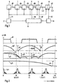
- FIG. 1 shows a circuit for sample rate conversion with a filter combination 1, 2, 3 according to the invention, which is expanded by a decimation device 4.
- the extended filter combination is between a signal source 5 and a buffer memory 6 arranged at the output 6.1 an output data sequence d2 with the desired Sampling frequency f2 is removable.
- the signal source 5 is a first clock source 7 connected, which provides a first clock f1, which is also known as a digitization clock or An input clock serves and thus determines the data rate of an input data sequence d1 second clock source 8 supplies a second clock f2, the output clock, and is like the first Clock source 7 connected to a control device 9.
- This low-pass filter 1 has a double zero in the range of half the sampling frequency 0.5 ⁇ f1 and thus also 1.5 times the sampling frequency.
- the pass and attenuation curve has a soft amplitude response, so that signals are attenuated in amplitude from 0.2 times the frequency of the sampling clock f1.
- the damping at the zero point has at least the value a1 for a larger frequency range, cf. Fig. 2.
- a data sequence d4 can be tapped at the output of the input low pass 1.
- the input low pass 1 is followed by a fixed interpolation filter 2, which is often also called Half band filter is called. It is characterized in that with its help the Number of samples compared to the input data sequence d1 by interpolation is doubled.
- the new scan sequence is transmitted as data sequence d5 to the next one time-variable interpolation filter 3 output, with some of the values in parallel as Basic values are available - the processing cycle is f1 through the first cycle
- a simultaneous frequency doubling of the processing clock is possibly useful where this clock increase is easily possible, e.g. because the Data rate of the data sequence d1 is significantly lower than the system clock.
- the fixed interpolation filter 2 contains a low-pass filter whose amplitude response tp2 it is specified that at least one double zero is in the range of the sampling frequency f1 with the damping a2 (Fig. 2) is present and from about half to 1.5 times Sampling frequency of the attenuation curve has at least the value a3 (FIG. 2).
- the fixed interpolation filter 2 can be designed so that the unwanted attenuation of higher signal frequencies due to the input low pass 1 is compensated for by a certain increase in altitude.
- Input low pass 1 and interpolation filter 2 forms one for the input data sequence d1 resulting low-pass filter, whose blocking range is slightly below half the sampling frequency 0.5 ⁇ f1 begins and extends slightly beyond 1.5 times the sampling frequency.
- Frequency mirroring repeats that between 2.5 times and 3.5 times Sampling frequency and at correspondingly higher frequencies.
- the signal components With a sampling frequency f1 of 20 MHz, the signal components usually also interfere, which are at twice the sampling frequency 2 ⁇ f1. These signal components are suppressed by means of the filter properties of a time-variable interpolation filter 3, the the fixed interpolation filter 2 follows. Any time values assigned Interpolation takes place in this time-variable Inberpolationsfilter 3, whose input is fed with the fixed base values from the fixed interpolation filter 2.
- the Output values of the interpolation correspond to a data sequence d6, the values of which are synchronous are output with the first clock f1.
- the coupling with the output clock f2 usually does not yet take place in the time-variable interpolation filter 3.
- the time-variable interpolation filter 3 is replaced by a linear one Interpolator (see Fig. 5) realized.
- Its amplitude response tp3 corresponds to one Low pass behavior and has a zero at twice the sampling frequency 2 ⁇ f1 Range of this zero has at least the damping value a4 (FIG. 2) for the intended suppression of the interference frequencies this is sufficient, improvements are of course higher order interpolators.
- the default of Interpolation time is determined by the control device 9, the one outputs the corresponding time difference signal td for each sample to be interpolated.
- the respective time difference signal td is calculated from the temporal Evaluation of the two cycles f1, f2 taking into account the closest base values.
- the Indian Decimation device 4 existing low-pass filter is of the respective decimation factor df dependent, which defines a moving data window, which depending on the filter level for Forming an average of weighted or unweighted samples is used Circuit 4 is ineffective at decimation factor 1.
- Control device 9 before the respective integer decimation factor df.
- the Data sequence d3 at terminal 4.2 is temporally coupled to the first clock f1.
- the temporal modulation range of the interpolator 3 is not an octave there are no clock overlap problems. It is also possible that the buffer memory 6 between the time-variable interpolation filter 3 and the Decimation device 4 is inserted, then the clock control of the Decimation stage 4 can be coupled to the second clock source 8.
- the circuit shown in Figure 1 as a block diagram can be in the individual Functional units, of course, in whole or in part also by means of a fast one Realize processor and associated programs.
- a numerical example should show how the change in the sampling rate is distributed to the filter combination. Should the Sampling frequency can be changed by a factor of 7.34, so the hybrid system a scan conversion by a factor of 0.9175 and the decimation device one Sampling rate reduction by a factor of 8. The hybrid system first doubles the Sampling rate (strictly speaking, only the number of samples is doubled and not the actual sampling clock, see explanations above) and forms about the Time difference signal td the reduction factor 1.835.
- the sampling frequency f1 is 20.25 MHz.
- the Input data sequence d1 corresponds approximately to a video signal whose upper limit frequency is at 6 MHz.
- the soft amplitude response tp1 des Input low pass 1 shown The upper frequencies of the video signal d1, approximately from 2.5 MHz are already reduced in amplitude.
- the third line is the Amplitude response tp2 of the low-pass filter shown in the fixed interpolation filter 2 Raising or lowering higher signal ranges corresponds to the course of the dashed line b in the pass band.
- the fourth line is the amplitude response tp3 shown a linear interpolator 3, the two inputs of which are adjacent Samples from the fixed interpolation filter 2 are fed.
- the amplitude response a / dB of the filter curves in FIG. 2 corresponds to a logarithmic one Representation and represents a range of approximately 45 dB for each curve.
- the fifth line in Fig. 2 finally shows the amplitude response of the entire filter combination after the Decimation device 4.
- the set value of the goes into this amplitude response Sampling rate reduction in the hybrid interpolation filter 2.3 and in the Decimation device 4 a.
- an interpolated sampling frequency is present, which corresponds to 11 MHz and then finally in the decimation device 4 is reduced by a factor of 8.
- the amplitude response tp4 thus corresponds to one Sampling rate reduction by a factor of 14.7, in which all in the input data sequence d1 Frequencies that are above about 0.7 MHz must be suppressed what is realized by the filter combination 1,2,3,4.
- This narrow-band low-pass behavior shows the pass band of the amplitude response tp4.
- the areas with the frequency multiples of 11 MHz are sufficiently attenuated by the extended filter combination 1, 2, 3, 4 so that they are negligible for the output data sequence d2.
- the extended filter combination 1, 2, 3, 4 Through periodic mirroring the amplitude responses tp1 to tp3 at the sampling frequency f1 and the multiple values Of these, possible interference frequencies above the sampling frequency are also suppressed.
- the circuit contains two series-connected delay stages 12.1, 12.2, the respective delay time T1 of which is the same as the period of the first clock f1.
- the three taps on the delay chain are fed to a summing stage 13, the middle tap being conducted via a multiplier 14, which effects a weighting by a factor of 2.
- FIG. 4 An example of the fixed interpolation filter 2 is shown in FIG. 4. It contains one Delay chain from three delay stages 15.1, 15.2, 15.3 their respective Delay time T1 is equal to the period of the first clock f1. By different linkage of the sampled values tapped at the delay chain the individual frequency components form fixed support or sampling values s (T), s (1.5T), s (2T) and s (2.5T) formed.
- the embodiment of the Fixed interpolation filter 2 is characterized in that there is only one real one Multiplier, four delay stages and four adders / subtractors required.
- the Circuit configuration with the three-stage delay chain corresponds to a fixed one Third order interpolation filter.
- the filter coefficients do not change in this fixed interpolation filter 2, because the searched sample values are fixed in time with respect to the original sampling grid, from this follows the designation "fixed interpolation filter”.
- they are Filter coefficients of the time-variable interpolation filter 3 from the respective value of the Time difference signal td dependent, from this follows the designation "time variable Interpolation ".
- the input 2.1 of the first delay stage is located 15.1 at the first input of an adder 17 and its output at the first input of an Adders 18, with its second input, the input of the third delay stage 15.3 is connected, the output of which is at the second input of the first adder 17
- Output of the first adder 17 is with the minuend input and the output of the second adder 18 connected to the subtrahend input of a subtractor 19, whose output is multiplied 16 by the first input of a third Adder 20 is connected, the second input at the output of the second adder 18 and its output via a position shift stage 21 with an output 2.12 and a delay stage 15.4 is connected.
- the shift stage 21 halves the Output value of the third adder 20 and corresponds to a multiplier that is off is fed to a memory 22 with a multiplication factor 0.5 in the multiplier 16 It is a real multiplier that determines the value of the signal component the subtractor 19 changes the higher frequency range at the terminal 2.1 data sequence supplied corresponds to that read out from a memory 23 Multiplication factor b, this signal component is weakened or amplified and fed to the filtered signal by means of the third adder 20.
- the Multiplication factor b thus represents a filter coefficient, its modulation range ranges from about -3/8 to -1/8.
- the filter coefficient b causes an increase or Lowering the amplitude response for higher frequencies, cf. the dashed Pass curve b in the frequency diagram tp2 of FIG. 2.
- each base value s (T) to s (2.5T) can be determined, which can be tapped at the same time and correspond to sample values, each by half Period T1 of the input clock f1 are apart.
- the exit of the first Delay stage 15.1 forms the first output terminal 2.11
- the output of the Shift stage 21 forms the second output 2.12
- the output of the second Delay stage 15.2 forms the third output 2.13
- the output of the fourth Delay stage 15.4 finally forms the fourth output 2.14.
- That subsequent time-variable interpolation filter 3 needs even more base values, then can be generated with similar circuits. If the following time-variable interpolation filter 3 only performs a linear interpolation, then only the outputs 2.11 to 2.13 of the filter arrangement according to FIG. 4 are required.
- a The selection circuit then also determines for which pair of samples s (T), s (1.5T); or s (1.5T), s (2T) the time difference signal dt is the smallest and selects this sampling pair for the subsequent
- a linear interpolator 3 is shown schematically, which corresponds to the Time difference signal dt any interpolation between two samples carries out, which are fed to a first and second connection 3.1, 3.2. there the supplied samples are in each case by means of a time difference signal td dependent weighting device 24, 25 weighted.
- the time difference signal td determines which linear part of the output value the first and second scanning signal to have.
- a multiplier 24 multiplies the first sample at terminal 3.1 the time difference signal td and a multiplier 25 multiplies the second Sampling value at terminal 3.2 with the factor 1-td.
- An adder 26 adds both resulting values and the sum at its output 33 is the linearly interpolated Sample.
- the time difference signal td is one half Period duration 1/2 ⁇ T1 of the clock f1 standardized numerical value.
- An MTA decimation device 4 is shown schematically in FIG. 6.
- In the simplest Case contains an accumulator 27, a decimation switch 28 and one Differentiators 29.
- In higher order MTA decimation devices instead of an accumulator 27 a certain number of accumulators connected in series and correspondingly an equal number of differentiators instead of the one differentiator 29.
- the accumulators are controlled by the first clock f1 and the differentiators and the decimation switch 28 from the decimation clock df.
- the Data sequence supplied at input 4.1 is added in accumulator 27.
- the Decimation switch 28 turns on after a certain number of samples Accumulator content read in the differentiator 29, the value of that there subtracts stored accumulator content, i.e.
- the decimation device 4 thus corresponds to averaging over a number of Samples defined by a moving data window, the length of is dependent on the decimation factor df. Averaging requires because of reinforcing property of the MTA filter after the accumulator 27 or Differentiator 28 a normalization device 30 .. If the decimation factor df a If there is a power of two, a simple change of position or a new one is sufficient Job assignment for standardization. In any case the searched samples of the output data sequence d2 are available with the correct amplitude stand.
Landscapes
- Physics & Mathematics (AREA)
- Engineering & Computer Science (AREA)
- Computer Hardware Design (AREA)
- Mathematical Physics (AREA)
- Transmission Systems Not Characterized By The Medium Used For Transmission (AREA)
- Television Systems (AREA)
Description
Die Erfindung betrifft eine Filterkombination zur Umsetzung der Abtastrate eines digitalisierten Signals. Die ursprüngliche Abtastrate erfüllt dabei das Abtasttheorem, das besagt, daß das zu digitalisierende Signal bandbegrenzt ist und eine obere Grenzfrequenz aufweist, die kleiner als die halbe Abtastrate ist. Für die Erhöhung oder Erniedrigung der Abtastrate um beliebige Faktoren haben sich Filterkombinationen bewärt, die auch als hybride Systeme bezeichnet werden. Der Grundgedanke dabei ist, daß zunächst aus der tiefpaßgefilterten Eingangsdatenfolge ein analoges Signal gebildet wird, das mit der gewünschten Abtastrate wieder digitalisiert wird. In Zwischenstufen erfolgen selbstverständlich digitale und analoge Tiefpaßfilterungen, deren Grenzfrequenzen entsprechend den jeweiligen internen und externen Abtastraten und Signalfrequenzen angepaßt sind, damit in der Ausgangsdatenfolge keine Aliassignale entstehen.The invention relates to a filter combination for implementing the sampling rate digitized signal. The original sampling rate fulfills the sampling theorem that states that the signal to be digitized is band-limited and an upper cut-off frequency has less than half the sampling rate. For increasing or decreasing the Sampling rate around any factors have proven filter combinations, which as well hybrid systems are called. The basic idea is that initially from the low-pass filtered input data sequence an analog signal is formed, which with the desired sampling rate is digitized again. In intermediate stages of course digital and analog low-pass filtering, its cut-off frequencies according to the respective internal and external sampling rates and signal frequencies are adjusted so that no alias signals occur in the output data sequence.
Die Rekonstruktion eines analogen Signals innerhalb der Filterkombination mittels einer Digital/Analogumsetzung ist zwar grundsätzlich möglich, jedoch dient diese Betrachtungsweise vor allen Dingen der Erläuterung des Verfahrens. Für die tatsächliche Realisierung erweist sich die vollständige Rekonstruktion des analogen Signals als nicht erforderlich, denn über eine Interpolation der digitalen Abtastwerte lassen sich die gewünschten Zwischenwerte auf einer rein digitalen Ebene mit hoher Genauigkeit berechnen. Die Umsetzung in ein analoges Signal wäre ein unnötiger Umweg, der nicht erforderlich ist, denn für die Abtastratenumsetzung ist für jeweils einen neuen Abtastwert immer nur ein einziger Zwischenwert zwischen festen Stützwerten zu interpolieren. Der beidseitige analoge Signalverlauf zu diesem interpolierten Zwischenwert wird für die Ausgangsdatenfolge nicht benötigt Bei den festen Stützwerten kann es sich um tatsächliche und/oder interpolierte Abtastwerte handeln, in jedem Fall sind diese festen Stützwerte zeitlich durch ein fest vorgegebenes Abtastraster definiert. Das Filter, das die festen Stützwerte liefert, wird daher auch als festes oder zeitinvariantes Interpolationsfilter bezeichnet. In der Regel ist die Frequenz dieses neuen Abtastrasters um eine Zweierpotenz höher als die ursprüngliche Abtastfrequenz. Eine ausführliche Behandlung derartiger Filterkombinationen erfolgt beispielsweise in "IEEE, Transactions on Acoustics, Speech and Signal Processing", Bd. ASSP-32, Nr. 3, Juli 1984, Seiten 577 bis 591 unter dem Titel "Digital Methods for Conversion Between Arbitrary Sampling Frequendes", Autor: T.A. Ramstad.The reconstruction of an analog signal within the filter combination using a Digital / analog conversion is possible in principle, but this serves Consideration above all of the explanation of the process. For the actual Realization proves the complete reconstruction of the analog signal as not required, because the interpolation of the digital samples allows the desired intermediate values on a purely digital level with high accuracy to calculate. The conversion into an analog signal would be an unnecessary detour, which is not is necessary, because for the sample rate conversion there is a new one Sampling value always only a single intermediate value between fixed base values interpolate. The bilateral analog signal curve to this interpolated The intermediate value is not required for the output data sequence Base values can be actual and / or interpolated samples, in in any case, these fixed base values are temporally defined by a fixed sampling grid Are defined. The filter that provides the fixed base values is therefore also called a fixed or time-invariant interpolation filter. As a rule, the frequency of this is new Scanning grids by a power of two higher than the original sampling frequency. A Extensive treatment of such filter combinations takes place, for example, in "IEEE, Transactions on Acoustics, Speech and Signal Processing ", Vol. ASSP-32, No. 3, July 1984, Pages 577 to 591 under the title "Digital Methods for Conversion Between Arbitrary Sampling Frequendes ", author: T.A. Ramstad.
In der EP-Patentanmeldung 96 11 9505.4 (= ITT Case: 1719) ist eine digitale Filterkombination zur Interpolation von Abtastwerten eines digitalisierten Signals beschrieben, mit der die Abtastrate digitalisierter Video- oder Audiosignale um ein beliebiges Zahlenverhältnis verändert werden kann. Die Schaltung enthält dabei ein festes Interpolationsfilter dritter Ordnung, mit dem die Anzahl der vorhandenen Abtastwerte durch die Bildung von interpolierten Zwischenwerten verdoppelt wird. Einer Periode des ursprünglichen Abtasttaktes sind nun zwei Abtastwerte zugeordnet. Dies kommt für die weitere Verarbeitung gleichsam einer Verdoppelung der ursprünglichen Abtastrate gleich, denn die zur Verfügung stehenden Abtastwerte entsprechen nun einem Abtastraster mit der halben Periodendauer. An das feste Interpolationsfilter schließt sich ein zeitvariables Interpolationsfilter zweiten Grades an, das aus der neuen Abtastfolge für beliebigen Zeitpunkte Zwischenwerte für die gewünschte Ausgangsdatenfolge berechnen kann.In EP patent application 96 11 9505.4 (= ITT Case: 1719) there is a digital one Filter combination for interpolating samples of a digitized signal described with which the sampling rate of digitized video or audio signals around any number ratio can be changed. The circuit contains one fixed third-order interpolation filter with which the number of available Samples are doubled by the formation of interpolated intermediate values. Two samples are now assigned to a period of the original sampling clock. This comes as a doubling of the further processing original sampling rate the same, because the available sampling values now correspond to a scanning grid with half the period. The firm Interpolation filter is followed by a time-variable second-degree interpolation filter, the intermediate values for the from the new scan sequence for any points in time can calculate the desired output data sequence.
Wenn die ein- und ausgangsseitige Abtastrate einander ähnlich sind, dann hält sich der Filteraufwand in Grenzen. Anders sieht es aus, wenn die beiden Abtastraten sehr unterschiedlich sind, weil dann durch Spiegelungen des vorhandenen Signalspektrums bei der neuen Abtastrate und den zugehörigen Frequenzvielfachwerten Aliassignale im Nutzspektrum entstehen können. Die Unterdrückung dieser Frequenzanteile im Signalspektrum, die meist vor der Abtastratenumsetzung durchgeführt ist, erfordert aufwendige Tiefpaßfilter, beispielsweise Transversalfilter mit langen Verzögerungsketten. Noch aufwendiger wird die Bandbegrenzung, wenn die Bandbreite in mehreren Schritten einstellbar sein muß, weil das Abtastratenverhältnis innerhalb bestimmter Grenzen beliebig einstellbar sein soll. Die Bandbegrenzung des Bandsignals kann somit leicht sehr viel aufwendiger werden als die eigentliche Abtastratenwandlung. Für Konsumanwendungen ist der Aufwand, mit dem eine bestimmte Funktion realisiert wird, eine wichtige Größe, denn je größer der Schaltungsaufwand ist, desto größer ist die dafür aufzubringende Halbleiterfläche bei der monolithischen Integration. Und der Halbleiterflächenzuwachs geht bekanntlich überproportional in die Herstellungskosten ein.If the sampling rate on the input and output sides are similar to one another, then the one holds Filter effort within limits. It looks different if the two sampling rates are very different are different because then by mirroring the existing signal spectrum at the new sampling rate and the associated frequency multiple values alias signals in Usage spectrum can arise. The suppression of these frequency components in the Signal spectrum, which is usually carried out before the sample rate conversion, is required elaborate low-pass filters, for example transversal filters with long ones Delay chains. Band limitation becomes even more complex if the bandwidth must be adjustable in several steps because the sample rate ratio within certain limits should be adjustable. The band limitation of the band signal can easily become much more complex than the actual sample rate conversion. For consumer applications, the effort with which a certain function is implemented becomes an important variable, because the greater the circuit complexity, the greater the semiconductor surface to be applied for the monolithic integration. And the As is well known, semiconductor surface growth goes disproportionately into manufacturing costs on.
Es ist daher Aufgabe der Erfindung, den gesamten Schaltungsaufwand für eine beliebige Abtastratenumsetzung möglichst klein zu halten.It is therefore an object of the invention, the total circuit complexity for any To keep sample rate conversion as small as possible.
Die Lösung der Aufgabe wird durch eine Filterkombination entsprechend den
Merkmalen des Anspruchs 1 erreicht. Der Grundgedanke der Erfindung besteht darin,
daß die Schaltung zur Bandbegrenzung und die Schaltung zur Abtastratenwandlung
miteinander verschmolzen werden. Dabei wird die Abtastratenwandlung und die damit
verbundene Bandbegrenzung durch das Zusammenwirken an sich bekannter Filterstufen
erreicht. Die Erfindung macht sich dabei zunutze, daß nicht nur der Durchlaß- und
Sperrbereich des Eingangstiefpaßes für die erforderliche Bandbegrenzung entscheidend
ist, sondern daß bei geschickter Kombination der an der Abtastratenumsetzung
beteiligten Filter die Anforderung an das einzelne Filter reduziert werden kann, weil der
resultierende gemeinsame Amplitudengang im interessierenden Frequenzbereich
insgesamt eine ausreichende Signaldämpfung bewirkt. Hierbei werden auch die
gespiegelten Bereiche der Amplitudengänge mit einbezogen, um störende Frequenzen
und Frequenzvielfachwerte zu unterdrücken. Es brauchen dabei nur solche
Störfrequenzen berücksichtigt zu werden, die in dem jeweiligen System auch tatsächlich
auftreten können und nicht schon durch die grundsätzlichen Eigenschaften der
Schaltungstechnologie, der Wiedergabeeinrichtung oder z.B. des Betrachters unterdrückt
sind. Die erforderliche Signaldämpfung hängt auch von der subjektiven
Störempfindlichkeit ab, die bei Videosignalen geringer als bei Audiosignalen istThe problem is solved by a filter combination according to the
Features of
Die Filterkombination nach der Erfindung kann dazu dienen, den Verarbeitungstakt eines digitalisierten Signals an die tatsächliche Signalbandbreite anzupassen. Dies ist beispielsweise erforderlich, wenn eine Überabtastung vorliegt oder ein relativ schmalbandiges Signal in einem breitbandigen Signalgemisch enthalten ist. Die Abtastratenumsetzung kann aber auch den Signalinhalt verändern, beispielsweise komprimieren oder expandieren. Mit der Komprimierung kann der Speicherbedarf bei der Signalspeicherung reduziert werden. Die Erfindung ermöglicht eine Anpassung unterschiedlicher Abtastraten von Signalen, beispielsweise die Anpassung einer mit einem festen Takt verkoppelten Datenfolge an den vorgegebenen Systemtakt eines anderen Verarbeitungssystems. Bei Videosignalen ist dabei auch eine Änderung der Darstellungsgröße, insbesondere eine Verkleinerung, des jeweiligen Bildes auf dem Bildschirm eines Fernsehempfängers oder einer Multimediawiedergabeeinrichtung möglich. Es lassen sich auf diese Weise Standbilder, laufende Fernsehbilder, mit dem Rechner erzeugte Bilder oder die Bilder anderer Bildquellen in beliebig verkleinerter Form in einem Bildschirmfenster darstellen. Diese eingeblendeten Bilder können auch als Menüfelder dienen.The filter combination according to the invention can serve the processing clock adapt a digitized signal to the actual signal bandwidth. This is for example required if there is oversampling or relative narrowband signal is contained in a broadband signal mixture. The Sampling rate conversion can also change the signal content, for example compress or expand. With compression, the memory requirement can be reduced signal storage can be reduced. The invention enables adaptation different sampling rates of signals, for example the adaptation of one with a fixed clock coupled data sequence to the specified system clock other processing system. With video signals there is also a change in the Display size, in particular a reduction, of the respective image on the Screen of a television receiver or a multimedia player possible. In this way, still pictures, running TV pictures, with the Computer generated images or the images of other image sources in any reduced size Display shape in a screen window. These superimposed images can also be used as Menu fields serve.
Die Filterkombination nach der Erfindung enthält im Eingang einen Eingangstiefpaß, der im Bereich der halben und 1,5-fachen Abtastfrequenz eine ausreichende Dämpfung hat Anschließend folgt das hybride Filtersystem aus einem festen und einem zeitvariablen Interpolationsfilter. Das hybride Filtersystem hat im Bereich der einfachen und doppelten Abtastfrequenz jeweils eine hohe Dämpfung. Der Dämpfungsverlauf zwischen der halben und 1,5-fachen Abtastfrequenz und bei den zugehörigen periodischen Spiegelbereichen ist zwar niedriger, aber insgesamt ausreichend. Hohe Dämpfungswerte bei bestimmten Frequenzbereichen lassen sich durch ein- oder mehrfache Nullstellen der Übertragungsfunktionen realisieren. Der Frequenzumfang dieser Sperrbereiche hängt vom Verlauf der Übertragungsfunktion, insbesondere der Anzahl der in diesem Frequenzbereich vorhandenen Nullstellen, und der gewünschten Dämpfung ab. Mit dem zeitvariablen Interpolationsfilter wird in der Regel eine Interpolation innerhalb einer Oktave realisiert Für größere Änderungen der Abtastfrequenz durchläuft das Signal dann noch eine Dezimierungseinrichtung mit einem zugehörigen Tiefpaß, der dann ebenfalls in die Filterkombination mit einbezogen wird. Besonders voreiteilhaft für die Reduktion des Schaltungsaufwandes ist es, wenn der ganzzahlige Dezimierungsfaktor eine variable Potenz von 2 ist, weil dann die Verstärkung der Dezimierungseinrichtung durch eine einfache Stellenverschiebung oder neue Stellenzuordnung der Ausgangsdaten rückgängig gemacht werden kann..The filter combination according to the invention contains an input low-pass filter in the input has sufficient attenuation in the range of half and 1.5 times the sampling frequency The hybrid filter system then follows from a fixed and a time variable Interpolation. The hybrid filter system has in the range of single and double Sampling frequency high attenuation. The course of damping between the half and 1.5 times the sampling frequency and the associated periodic Mirror areas are lower, but overall sufficient. High damping values in certain frequency ranges, the zeros can be reset by one or more times Realize transfer functions. The frequency range of these restricted areas depends on the course of the transfer function, in particular the number of those in it Frequency range existing zeros, and the desired damping. With the time-variable interpolation filter is usually an interpolation within a Octave realized For larger changes in the sampling frequency, the signal runs through then a decimation device with an associated low pass, which then is also included in the filter combination. Particularly advantageous for them It is a reduction of the circuit effort if the integer decimation factor is a variable power of 2 because then the gain of the decimator by simply shifting positions or assigning new positions to the output data can be undone ..
Die Erfindung und ein vorteilhaftes Ausführungsbeispiel wird nun anhand der Figuren
der Zeichnung näher dargestellt:
Fig. 1 zeigt eine Schaltung zur Abtastratenumsetzung mit einer Filterkombination 1,2,3
nach der Erfindung, die durch eine Dezimierungseinrichtung 4 erweitert ist. Die
erweiterte Filterkombination ist zwischen einer Signalquelle 5 und einem Pufferspeicher
6 angeordnet, an dessen Ausgang 6.1 eine Ausgangsdatenfolge d2 mit der gewünschten
Abtastfrequenz f2 abnehmbar ist. Mit der Signalquelle 5 ist eine erste Taktquelle 7
verbunden, die einen ersten Takt f1 liefert, der auch als Digitalisierungstakt oder
Eingangstakt dient und damit die Datenrate einer Eingangsdatenfolge d1 bestimmt Eine
zweite Taktquelle 8 liefert einen zweiten Takt f2, den Ausgangstakt, und ist wie die erste
Taktquelle 7 mit einer Steuereinrichtung 9 verbunden.1 shows a circuit for sample rate conversion with a
Die Filterkombination enthält im Eingang einen Eingangstiefpaß 1, dessen
Amplitudengang tp1 beispielsweise durch einen Tiefpaß zweiter Ordnung mit der
Übertragungsfunktion H(z) = (1 + z-1)2 realisiert ist. Dieser Tiefpaß 1 hat im Bereich der
halben Abtastfrequenz 0,5×f1 und damit auch beider 1,5-fachen Abtastfrequenz eine
doppelte Nullstelle. Die Durchlaß- und Dämpfungskurve hat einen weichen
Amplitudengang, so daß bereits Signale ab der 0,2-fachen Frequenz des Abtasttaktes f1 in
der Amplitude gedämpft werden. Die Dämpfung bei der Nullstelle hat für einen
größeren Frequenzbereich mindestens den Wert a1, vgl. Fig. 2. Am Ausgang des
Eingangtiefpasses 1 ist eine Datenfolge d4 abgreifbar.The filter combination contains an input low-
Dem Eingangstiefpaß 1 folgt ein festes Interpolationsfilter 2, das oft auch als
Halbbandfilter bezeichnet wird. Es zeichnet sich dadurch aus, daß mit seiner Hilfe die
Anzahl der Abtastwerte gegenüber der Eingangsdatenfolge d1 durch eine Interpolation
verdoppelt wird. Die neue Abtastfolge wird als Datenfolge d5 an das nachfolgende
zeitvariable Interpolationsfilter 3 abgegeben, wobei ein Teil der Werte parallel als
Stützwerte zur Verfügung steht - der Verarbeitungstakt ist durch den ersten Takt f1
bestimmt Eine gleichzeitige Frequenzverdoppelung des Verarbeitungstaktes ist
gegebenenfalls dort sinnvoll, wo diese Takterhöhung leicht möglich ist, z.B. weil die
Datenrate der Datenfolge d1 wesentlich niedriger als der Systemtakt liegt.The input
Das feste Interpolationsfilter 2 enthält einen Tiefpaß dessen Amplitudengang tp2 so
vorgegeben ist, daß im Bereich der Abtastfrequenz f1 mindestens eine doppelte Nullstelle
mit der Dämpfung a2 (Fig. 2) vorhanden ist und etwa von der halben bis zur 1,5-fachen
Abtastfrequenz der Dämpfungsverlauf mindestens den Wert a3 (Fig. 2) aufweist. Bei
geeigneter Realisierung kann das feste Interpolationsfilter 2 so ausgebildet sein, daß die
unerwünschte Dämpfung höherer Signalfrequenzen infolge des Eingangstiefpasses 1
durch eine gewissen Höhenanhebung wieder ausgeglichen wird. Die Kombination aus
Eingangstiefpaß 1 und Interpolationsfilter 2 bildet für die Eingangsdatenfolge d1 einen
resultierenden Tiefpaß, dessen Sperrbereich etwas unterhalb der halben Abtastfrequenz
0,5×f1 beginnt und etwas über die 1,5-fache Abtastfrequenz hinaus reicht. Durch
Frequenzspiegelung wiederholt sich das zwischen der 2,5-fachen und 3,5-fachen
Abtastfrequenz und bei entsprechend höheren Frequenzen.The fixed
Bei einer Abtastfrequenz f1 von 20 MHz stören in der Regel auch die Signalkomponenten,
die bei der doppelten Abtastfrequenz 2×f1 liegen. Diese Signalkomponenten werden
mittels der Filtereigenschaften eines zeitvariablen Interpolationsfilters 3 unterdrückt, das
dem festen Interpolationsfilter 2 folgt. Die beliebigen Zeitwerten zugeordnete
Interpolation findet in diesem zeitvariablen Inberpolationsfilter 3 statt, dessen Eingang
mit den festen Stützwerten aus dem festen Interpolationsfilter 2 gespeist ist. Den
Ausgangswerten der Interpolation entspricht eine Datenfolge d6, deren Werte synchron
mit dem ersten Takt f1 ausgegeben werden. Die Verkopplung mit dem Ausgangstakt f2
findet in der Regel im zeitvariablen Interpolationsfilter 3 noch nicht statt.With a sampling frequency f1 of 20 MHz, the signal components usually also interfere,
which are at twice the
Im einfachsten Fall wird das zeitvariable Interpolationsfilter 3 durch einen linearen
Interpolator (vergl. Fig. 5) realisiert. Sein Amplitudengang tp3 entspricht einem
Tiefpaßverhalten und hat bei der doppelten Abtastfrequenz 2×f1 eine Nullstelle, die im
Bereich dieser Nullstelle mindestens den Dämpfungswert a4 (Fig. 2) aufweist Für die
beabsichtigte Unterdrückung der Störfrequenzen ist dies ausreichend, Verbesserungen
stellen selbstverständlich Interpolatoren höherer Ordnung dar. Die Vorgabe des
Interpolationszeitpunktes wird durch die Steuereinrichtung 9 bestimmt, die ein
entsprechendes Zeitdifferenzsignal td für jeden zu interpolierenden Abtastwert abgibt.
Die Berechnung des jeweiligen Zeitdifferenzsignals td erfolgt aus der zeitlichen
Auswertung der beiden Takte f1, f2 unter Einbeziehung der nächstliegenden Stützwerte.In the simplest case, the time-
Da mit derartigen Schaltungen zur Abtastratenumsetzung in der Regel eine deutliche
Abtastratenreduktion durchgeführt wird, schließt sich der Filterkombination 1,2,3 die
bereits genannte Dezimierungseinrichtung 4 an, mit der eine Abtastratenreduktion um
einen ganzzahligen Faktor, insbesondere um eine Potenz von 2, durchführbar ist Für
derartige Schaltungen eignen sich insbesondere MTA-Filter (= Moving Time Averager)
einfacher oder höherer Ordnung wegen ihres einfachen Aufbaues. Der in der
Dezimierungseinrichtung 4 vorhandene Tiefpaß ist vom jeweiligen Dezimierungsfaktor
df abhängig, der ein mitlaufendes Datenfenster definiert, das je nach Filtergrad zur
Bildung eines Mittelwertes aus gewichteten oder ungewichteten Abtastwerten dient
Beim Dezimierungsfaktor 1 ist die Schaltung 4 unwirksam. In der Regel gibt die
Steuereinrichtung 9 den jeweiligen ganzzahligen Dezimierungsfaktor df vor. Die
Datenfolge d3 an der Klemme 4.2 ist zeitlich mit dem ersten Takt f1 verkoppelt. Den
zeitlichen Ausgleich zum zweiten Takt f2 stellt der Pufferspeicher 6 her, dessen Eingang
mit der ersten Taktquelle 7 und dessen Ausgang mit der zweiten Taktquelle 8 verbunden
ist. Solange der zeitliche Aussteuerbereich des Interpolators 3 eine Oktave nicht
überschreitet, ergeben sich keine Taktüberlappungsprobleme. Es ist auch möglich, daß
der Pufferspeicher 6 zwischen dem zeitvariablen Interpolationsfilter 3 und der
Dezimierungseinrichtung 4 eingefügt wird, dann wird auch die Taktsteuerung der
Dezimierungsstufe 4 mit der zweiten Taktquelle 8 koppelbar.Since with such circuits for sample rate conversion usually a clear
Sampling rate reduction is performed, the
Die in Figur 1 als Blockschaltbild dargestellte Schaltung läßt sich in den einzelnen Funktionseinheiten selbstverständlich ganz oder teilweise auch mittels eines schnellen Prozessors und zugehöriger Programme realisieren. Ein Zahlenbeispiel soll zeigen, wie die Änderung der Abtastrate auf die Filterkombination aufgeteilt wird. Soll die Abtastfrequenz um den Faktor 7,34 geändert werden, so vollzieht das hybride System eine Abtastwandlung um den Faktor 0,9175 und die Dezimierungseinrichtung eine Abtastratenreduktion um den Faktor 8. Das hybride System verdoppelt zuerst die Abtastrate (genau genommen wird nur die Anzahl der Abtastwerte verdoppelt und nicht der eigentliche Abtasttakt, siehe obige Ausführungen) und bildet über das Zeitdifferenzsignal td den Reduktionsfaktor 1,835.The circuit shown in Figure 1 as a block diagram can be in the individual Functional units, of course, in whole or in part also by means of a fast one Realize processor and associated programs. A numerical example should show how the change in the sampling rate is distributed to the filter combination. Should the Sampling frequency can be changed by a factor of 7.34, so the hybrid system a scan conversion by a factor of 0.9175 and the decimation device one Sampling rate reduction by a factor of 8. The hybrid system first doubles the Sampling rate (strictly speaking, only the number of samples is doubled and not the actual sampling clock, see explanations above) and forms about the Time difference signal td the reduction factor 1.835.
In Fig. 2 ist das Frequenzschema der Eingangsdatenfolge d1 und der Amplitudengang
a/dB der Filter von Fig. 1 dargestellt. Die Abtastfrequenz f1 beträgt 20,25 MHz. Die
Eingangsdatenfolge d1 entspricht einem Videosignal dessen obere Grenzfrequenz etwa
bei 6 MHz liegt. In der nächsten Zeile ist der weiche Amplitudengang tp1 des
Eingangstiefpasses 1 dargestellt Die oberen Frequenzen des Videosignals d1, etwa ab 2,5
MHz, werden dabei bereits in der Amplitude abgesenkt. In der dritten Zeile ist der
Amplitudengang tp2 des Tiefpasses im festen Interpolationsfilter 2 dargestellt Die
Anhebung oder Absenkung höherer Signalbereiche entspricht dem Verlauf der
gestrichelten Linie b im Durchlaßbereich. In der vierten Zeile ist der Amplitudengang
tp3 eines linearen Interpolators 3 dargestellt, dessen beide Eingänge mit benachbarten
Abtastwerten aus dem festen Interpolationsfilter 2 gespeist sind.2 is the frequency scheme of the input data sequence d1 and the amplitude response
a / dB of the filter of Fig. 1 shown. The sampling frequency f1 is 20.25 MHz. The
Input data sequence d1 corresponds approximately to a video signal whose upper limit frequency
is at 6 MHz. In the next line is the soft amplitude response tp1 des
Input
Der Amplitudengang a/dB der Filterkurven in Fig. 2 entspricht einer logarithmischen
Darstellung und stellt für jede Kurve einen Bereich von etwa 45 dB dar. Die fünfte Zeile
in Fig. 2 zeigt schließlich den Amplitudengang der gesamten Filterkombination nach der
Dezimierungseinrichtung 4. In diesen Amplitudengang geht der eingestellte Wert der
Abtastratenreduktion im hybriden Interpolationsfilter 2,3 und in der
Dezimierungseinrichtung 4 ein. Für das dargestellte Beispiel ist angenommen, daß am
Ausgang des zeitvariablen Interpolationsfilters 3 eine interpolierte Abtastfrequenz
vorliegt, die 11 MHz entspricht und die dann schließlich in der Dezimierungseinrichtung
4 noch um den Faktor 8 reduziert wird. Der Amplitudengang tp4 entspricht somit einer
Abtastratenreduktion um den Faktor 14,7, bei dem in der Eingangsdatenfolge d1 alle
Frequenzen, die oberhalb von etwa 0,7 MHz liegen, unterdrückt werden müssen, was
durch die Filterkombination 1,2,3,4 realisiert ist. Dieses schmalbandige Tiefpaßverhalten
zeigt der Durchlaßbereich des Amplitudengangs tp4. Die Nebenmaxima des
Amplitudengangs tp4 entsprechen dem theoretischen Amplitudengang eines MTA-Dezimierers,
dessen Eingangsdatenfolge 11 MHz aufweist und dessen
Dezimierungsfaktor df = 8 ist. Bei Videosignalen stören dies Nebenmaxima nicht mehr.
Wenn die Dämpfung dort nicht ausreicht, dann muß lediglich ein MTA-Filter höherer
Ordnung verwendet werden. Die Bereiche mit den Frequenzvielfachwerten von 11 MHz
werden durch die erweiterte Filterkombination 1, 2, 3, 4 ausreichend gedämpft, so daß sie
für die Ausgangsdatenfolge d2 vernachlässigbar sind. Durch die periodische Spiegelung
der Amplitudengänge tp1 bis tp3 bei der Abtastfrequenz f1 und den Vielfachwerten
davon, werden auch mögliche Störfrequenzen oberhalb der Abtastfrequenz unterdrückt.The amplitude response a / dB of the filter curves in FIG. 2 corresponds to a logarithmic one
Representation and represents a range of approximately 45 dB for each curve. The fifth line
in Fig. 2 finally shows the amplitude response of the entire filter combination after the
Decimation device 4. The set value of the goes into this amplitude response
Sampling rate reduction in the hybrid interpolation filter 2.3 and in the
Decimation device 4 a. For the example shown it is assumed that on
Output of the time-
In Fig. 3 ist ein Beispiel für einen Eingangstiefpaß 1 dargestellt, dessen Amplitudengang
einem Tiefpaß zweiter Ordnung entspricht und die Übertragungsfunktion H(z) = (1 + z-1
)2 aufweist. Die Schaltung enthält zwei hintereinandergeschaltete Verzögerungsstufen
12.1, 12.2, deren jeweilige Verzögerungszeit T1 der Periode des ersten Taktes f1 gleich ist.
Die drei Abgriffe an der Verzögerungskette sind einer Summierstufe 13 zugeführt, wobei
der mittlere Abgriff über einen Multiplizierer 14 geführt ist, der eine Gewichtung mit
dem Faktor 2 bewirkt.3 shows an example of an input low-
Ein Beispiel für das feste Interpolationsfilter 2 ist in Fig. 4 dargestellt Es enthält eine
Verzögerungskette aus drei Verzögerungsstufen 15.1, 15.2, 15.3 deren jeweilige
Verzögerungszeit T1 der Periodendauer des ersten Taktes f1 gleich ist. Durch
unterschiedliche Verknüpfung der an der Verzögerungskette abgegriffenen Abtastwerte
werden die einzelnen Frequenzkomponenten zur Bildung fester Stütz- oder Abtastwerte
s(T), s(1,5T), s(2T) und s(2,5T) gebildet Das in Fig. 1 dargestellte Ausführungsbeispiel des
festen Interpolationsfilters 2 zeichnet sich dadurch aus, daß es nur einen einzigen echten
Multiplizierer, vier Verzögerungsstufen und vier Addierer/Subtrahierer erfordert. Die
Schaltungskonfiguration mit der dreistufigen Verzögerungskette entspricht einem festen
Interfpolationsfilter dritter Ordnung.An example of the fixed
Die Filterkoeffizienten ändern sich bei diesem festen Interpolationsfilter 2 nicht, denn die
gesuchten Abtastwerte liegen zeitlich gegenüber dem ursprünglichen Abtastraster fest,
daraus folgt die Bezeichnung "festes Interpolationsfilter". Demgegenüber sind die
Filterkoeffizienten des zeitvariablen Interpolationsfilters 3 von dem jeweiligen Wert des
Zeitdifferenzsignals td abhängig, daraus folgt die Bezeichnung "zeitvariables
Interpolationsfilter".The filter coefficients do not change in this fixed
In dem Schaltungsbeispiel von Fig. 4 liegt der Eingang 2.1 der ersten Verzögerungsstufe
15.1 am ersten Eingang eines Addierers 17 und deren Ausgang am ersten Eingang eines
Addierers 18, mit dessen zweitem Eingang der Eingang der dritten Verzögerungsstufe
15.3 verbunden ist, deren Ausgang am zweiten Eingang des ersten Addierers 17 liegt Der
Ausgang des ersten Addierers 17 ist mit dem Minuend-Eingang und der Ausgang des
zweiten Addierers 18 mit dem Subtrahend-Eingang eines Subtrahierers 19 verbunden,
dessen Ausgang über einen Multiplizierst 16 mit dem ersten Eingang eines dritten
Addierers 20 verbunden ist, dessen zweiter Eingang am Ausgang des zweiten Addierers
18 und dessen Ausgang über eine Stellen-Schiebestufe 21 mit einem Ausgang 2.12 und
einer Verzögerungsstufe 15.4 verbunden ist. Die Schiebestufe 21 halbiert den
Ausgangswert des dritten Addierers 20 und entspricht einem Multiplizierer, der aus
einem Speicher 22 mit einem Multiplikationsfaktor 0,5 gespeist ist Beim Multiplizierer 16
handelt es sich um einen echten Multiplizierer, der den Wert der Signalkomponente aus
dem Subtrahierer 19 verändert, die einem höheren Frequenzbereich der an der Klemme
2.1 zugeführten Datenfolge entspricht Durch einen aus einem Speicher 23 ausgelesenen
Multiplikationsfaktor b wird diese Signalkomponente abgeschwächt oder verstärkt und
mittels des dritten Addierers 20 dem gefilterten Signal zugeführt. Der
Multiplikationsfaktor b stellt somit einen Filterkoeffizienten dar, dessen Aussteuerbereich
etwa von -3/8 bis -1/8 reicht. Der Filterkoeffizient b bewirkt eine Anhebung oder
Absenkung des Amplitudengangs für höhere Frequenzen, vgl. die gestrichelte
Durchlaßkurve b im Frequenzdiagramm tp2 von Fig. 2.In the circuit example of FIG. 4, the input 2.1 of the first delay stage is located
15.1 at the first input of an
Mit der Filterschaltung von Fig. 4 lassen sich vier Stützwerte s(T) bis s(2,5T) bestimmen,
die gleichzeitig abgreifbar sind und Abtastwerten entsprechen, die jeweils um eine halbe
Periode T1 des Eingangstaktes f1 auseinanderliegen. Der Ausgang der ersten
Verzögerungsstufe 15.1 bildet den ersten Ausgangsanschluß 2.11, der Ausgang der
Schiebestufe 21 bildet den zweiten Ausgang 2.12, der Ausgang der zweiten
Verzögerungsstufe 15.2 bildet den dritten Ausgang 2.13 und der Ausgang der vierten
Verzögerungsstufe 15.4 bildet schließlich den vierten Ausgang 2.14. Wenn das
nachfolgende zeitvariable Interpolationsfilter 3 noch mehr Stützwerte benötigt, dann
lassen sich diese mit ähnlichen Schaltungen erzeugen. Wenn das nachfolgende
zeitvariable Interpolationsfilter 3 lediglich eine lineare Interpolation durchführt, dann
werden nur die Ausgänge 2.11 bis 2.13 der Filteranordnung nach Fig. 4 benötigt. Eine
Auswahlschaltung legt dann noch fest, für welches Abtastwertepaar s(T), s(1,5T); oder
s(1,5T), s(2T) das Zeitdifferenzsignal dt am kleinsten ist und wählt dieses Abtastpaar für
die nachfolgende Interpolation aus.4, four base values s (T) to s (2.5T) can be determined,
which can be tapped at the same time and correspond to sample values, each by half
Period T1 of the input clock f1 are apart. The exit of the first
Delay stage 15.1 forms the first output terminal 2.11, the output of the
In Fig. 5 ist schematisch ein linearer Interpolator 3 dargestellt, der entsprechend dem
Zeitdifferenzsignal dt eine beliebige Interpolation zwischen zwei Abtastwerten
durchführt, die ihm an einem ersten und zweiten Anschluß 3.1, 3.2 zugeführt sind. Dabei
werden die zugeführten Abtastwerte jeweils mittels einer vom Zeitdifferenzsignal td
abhängigen Gewichtungseinrichtung 24, 25 gewichtet. Das Zeitdifferenzsignal td
bestimmt, welchen linearen Anteil am Ausgangswert das erste und zweite Abtastsignal
haben. Ein Multiplizierer 24 multipliziert den ersten Abtastwert an der Klemme 3.1 mit
dem Zeitdifferenzsignal td und ein Multiplizierer 25 multipliziert den zweiten
Abtastwert an der Klemme 3.2 mit dem Faktor 1-td. Ein Addierer 26 addiert beide
resultierende Werte und die Summe an seinem Ausgang 33 ist der linear interpolierte
Abtastwert. Bei dem Zeitdifferenzsignal td handelt es sich um ein auf die halbe
Periodendauer 1/2×T1 des Taktes f1 normierten Zahlenwert. 5, a
In Fig. 6 ist schematisch eine MTA-Dezimierungseinrichtung 4 dargestellt. Im einfachsten
Fall enthält diese einen Akkumulator 27, einen Dezimierungsschalter 28 und einen
Differenzierer 29. Bei MTA-Dezimierungseinrichtungen höherer Ordnung sind statt des
einen Akkumulators 27 eine bestimmte Anzahl von Akkumulatoren
hintereinandergeschaltet und entsprechend eine gleichgroße Anzahl von Differenzierern
statt des einen Differenzierers 29. Die Akkumulatoren sind vom ersten Takt f1 gesteuert
und die Differenzierer sowie der Dezimierungsschalter 28 vom Dezimierungstakt df. Die
am Eingang 4.1 zugeführte Datenfolge wird im Akkumulator 27 aufaddiert. Mittels des
Dezimierungsschalters 28 wird nach einer bestimmten Anzahl von Abtastwerten der
Akkumulatorinhalt in den Differenzierer 29 gelesen, der von diesem Wert den dort
gespeicherten Akkumulatorinhalt abzieht, also derjenigen Akkumulatorinhalt, der dem
vorausgehenden Dezimierungszeitpunkt zugeordnet war. Die Funktionsweise der
Dezimierungseinrichtung 4 entspricht damit der Mittelwertbildung über eine Anzahl von
Abtastwerte, die durch ein mitlaufendes Datenfenster definiert sind, dessen Länge von
dem Dezimierungsfaktor df abhängig ist. Die Mittelwertbildung erfordert wegen der
verstärkenden Eigenschaft des MTA-Filters nach dem Akkumulator 27 oder dem
Differenzierer 28 eine Normierungseinrichtung 30.. Wenn der Dezimierungsfaktor df eine
Zweierpotenz ist, dann reicht eine einfache Stellenverschiebung oder eine neue
Stellenzuordnung für die Normierung aus. In jedem Fall sollen am Ausgang 4.2 die
gesuchten Abtastwerte der Ausgangsdatenfolge d2 amplitudenrichtig zur Verfügung
stehen.An MTA decimation device 4 is shown schematically in FIG. 6. In the simplest
Case contains an
Claims (8)
- A digital filter combination for performing a sampling rate conversion of a first data sequence (d1), which is locked with a digitization clock (f1), to a second data sequence (d2), comprising a series combination of:a digital input low-pass filter (1) whose unmirrored and mirrored amplitude response (tp1) in the range of half and 1.5 times the frequency of the digitization clock (f1), respectively, as stop-band attenuation corresponds at least to a first attenuation value (a1) which lies in the range of a necessary total attenuation and whose amplitude response in the range of the frequency of the digitization clock shows virtually no attenuation;a time-invariant interpolation filter (2) for increasing the number of samples from that of the first data sequence (d1) by an integral factor, particularly by a factor of 2, with the amplitude response (tp2) of the time-invariant interpolation filter (2)in the range of the frequency of the digitization clock (f1) as stop-band attenuation corresponding at least to a second attenuation value (a2) which lies in the range of the necessary total attenuation, andin the frequency range between the stop bands defined by the input low-pass filter (1) at half and 1.5 times the frequency of the digitization clock (f1) as stop-band attenuation corresponding at least to a third attenuation value (a3) which lies between the second attenuation value (a2) and the nonattenuated value, so that the combination of input low-pass filter and interpolation filter gives a resultant low-pass filter whose stop band begins slightly below half the frequency of the digitization clock and extends slightly beyond 1.5 times the frequency of the digitization clock; anda time-varying interpolation filter (3) for interpolating a data sequence (d5) provided at the output of the time-invariant interpolation filter (2), the amplitude response (tp3) of the time-varying interpolation filter (3) having a low-pass characteristic with a stop band in the range of twice the frequency of the digitization clock (f1) whose stop-band attenuation corresponds at least to a fourth attenuation value (a4) which lies in the range of the necessary total attenuation.
- A filter combination as set forth in claim 1, characterized in that the sampling rate and/or the number of samples of an output data sequence (d6) of the time-varying interpolation filter (3) are reduced by an integral decimation factor (df) by means of a decimator (4).
- A filter combination as set forth in claim 1 or 2, characterized in that the input low-pass filter (1) is defined by a transfer function H(z) = (1 + z-1)p, where p is greater than or equal to 2.
- A filter combination as set forth in any one of claims 1 to 3, characterized in that the time-invariant interpolation filter (2) has an amplitude response (tp2) which is adjustable in the passband for higher frequencies by means of an applied coefficient (b).
- A filter combination as set forth in any one of claims 1 to 4, characterized in that the time-varying interpolation filter (3) implements a linear interpolation.
- A filter combination as set forth in claim 2, characterized in that the decimator (4) has essentially an MTA filter structure.
- A filter combination as set forth in claim 6, characterized in that the decimation factor (df) is a power of two.
- A filter combination as set forth in claim 7, characterized in that by means of a shift unit or bit allocation unit (30), particularly in the decimator (4), amplitude normalization is effected.
Priority Applications (5)
| Application Number | Priority Date | Filing Date | Title |
|---|---|---|---|
| EP97110914A EP0889588B1 (en) | 1997-07-02 | 1997-07-02 | Filter combination for sample rate conversion |
| DE59710269T DE59710269D1 (en) | 1997-07-02 | 1997-07-02 | Filter combination for sample rate conversion |
| KR1019980026542A KR19990013528A (en) | 1997-07-02 | 1998-07-02 | Filter combination system for sampling rate conversion |
| JP10187821A JPH1174758A (en) | 1997-07-02 | 1998-07-02 | Filter combination device for converting sampling rate |
| US09/110,009 US6137349A (en) | 1997-07-02 | 1998-07-02 | Filter combination for sampling rate conversion |
Applications Claiming Priority (1)
| Application Number | Priority Date | Filing Date | Title |
|---|---|---|---|
| EP97110914A EP0889588B1 (en) | 1997-07-02 | 1997-07-02 | Filter combination for sample rate conversion |
Publications (2)
| Publication Number | Publication Date |
|---|---|
| EP0889588A1 EP0889588A1 (en) | 1999-01-07 |
| EP0889588B1 true EP0889588B1 (en) | 2003-06-11 |
Family
ID=8226998
Family Applications (1)
| Application Number | Title | Priority Date | Filing Date |
|---|---|---|---|
| EP97110914A Expired - Lifetime EP0889588B1 (en) | 1997-07-02 | 1997-07-02 | Filter combination for sample rate conversion |
Country Status (5)
| Country | Link |
|---|---|
| US (1) | US6137349A (en) |
| EP (1) | EP0889588B1 (en) |
| JP (1) | JPH1174758A (en) |
| KR (1) | KR19990013528A (en) |
| DE (1) | DE59710269D1 (en) |
Cited By (1)
| Publication number | Priority date | Publication date | Assignee | Title |
|---|---|---|---|---|
| DE102005018858A1 (en) * | 2005-04-22 | 2006-11-02 | Infineon Technologies Ag | Digital filter for use in digital signal processing, sets predetermined value for respective closed-loop controlled time-delay registor |
Families Citing this family (43)
| Publication number | Priority date | Publication date | Assignee | Title |
|---|---|---|---|---|
| DE19860720A1 (en) * | 1998-12-23 | 2000-06-29 | Siemens Ag | Method for synchronizing multiple digital input signals |
| US6424687B1 (en) * | 1999-03-15 | 2002-07-23 | Cirrus Logic, Inc. | Method and device for alignment of audio data frames using interpolation and decimation |
| CN1300466A (en) * | 1999-03-26 | 2001-06-20 | 皇家菲利浦电子有限公司 | Converter |
| US6487573B1 (en) * | 1999-03-26 | 2002-11-26 | Texas Instruments Incorporated | Multi-rate digital filter for audio sample-rate conversion |
| KR100598702B1 (en) * | 2000-03-22 | 2006-07-11 | 넥스원퓨처 주식회사 | Measure system of receiving sensibility for receiving data |
| US7076315B1 (en) * | 2000-03-24 | 2006-07-11 | Audience, Inc. | Efficient computation of log-frequency-scale digital filter cascade |
| FR2819600B1 (en) * | 2001-01-16 | 2003-04-11 | Thomson Csf | METHOD AND DEVICE FOR GENERATING A RANDOM SIGNAL WITH CONTROLLED HISTOGRAM AND SPECTRUM |
| KR100421001B1 (en) * | 2001-02-20 | 2004-03-03 | 삼성전자주식회사 | Sampling rate conversion apparatus and method thereof |
| US6531969B2 (en) * | 2001-05-02 | 2003-03-11 | Portalplayer, Inc. | Resampling system and apparatus |
| JP3775258B2 (en) * | 2001-07-31 | 2006-05-17 | 株式会社デンソー | Filtering method and A / D converter having filter function |
| US6961395B2 (en) * | 2001-11-16 | 2005-11-01 | Nortel Networks Limited | Time variant filter implementation |
| GB2384376A (en) * | 2002-01-22 | 2003-07-23 | Zarlink Semiconductor Inc | Flexible decimator |
| US7764758B2 (en) * | 2003-01-30 | 2010-07-27 | Lsi Corporation | Apparatus and/or method for variable data rate conversion |
| EP1611679B1 (en) * | 2003-03-31 | 2015-07-15 | Callahan Cellular L.L.C. | Up and down sample rate converter |
| US7058464B2 (en) * | 2003-07-17 | 2006-06-06 | Ess Technology, Inc. | Device and method for signal processing |
| JP2005197770A (en) * | 2003-12-26 | 2005-07-21 | Sanyo Electric Co Ltd | Image signal processing apparatus, image signal processing method, and image signal processing program |
| KR100742836B1 (en) * | 2005-12-27 | 2007-07-25 | 엘지노텔 주식회사 | Method for converting sampling frequency by software in VoIP telephony |
| US8345890B2 (en) | 2006-01-05 | 2013-01-01 | Audience, Inc. | System and method for utilizing inter-microphone level differences for speech enhancement |
| US8194880B2 (en) | 2006-01-30 | 2012-06-05 | Audience, Inc. | System and method for utilizing omni-directional microphones for speech enhancement |
| US8744844B2 (en) | 2007-07-06 | 2014-06-03 | Audience, Inc. | System and method for adaptive intelligent noise suppression |
| US8204252B1 (en) | 2006-10-10 | 2012-06-19 | Audience, Inc. | System and method for providing close microphone adaptive array processing |
| US9185487B2 (en) * | 2006-01-30 | 2015-11-10 | Audience, Inc. | System and method for providing noise suppression utilizing null processing noise subtraction |
| US8204253B1 (en) | 2008-06-30 | 2012-06-19 | Audience, Inc. | Self calibration of audio device |
| US8849231B1 (en) | 2007-08-08 | 2014-09-30 | Audience, Inc. | System and method for adaptive power control |
| US8949120B1 (en) | 2006-05-25 | 2015-02-03 | Audience, Inc. | Adaptive noise cancelation |
| US8934641B2 (en) | 2006-05-25 | 2015-01-13 | Audience, Inc. | Systems and methods for reconstructing decomposed audio signals |
| US8150065B2 (en) * | 2006-05-25 | 2012-04-03 | Audience, Inc. | System and method for processing an audio signal |
| US8065355B2 (en) * | 2006-12-01 | 2011-11-22 | Samsung Electronics Co., Ltd. | Interpolation FIR filter having multiple data rates in mobile communication system and method of filtering data using the same |
| US8259926B1 (en) | 2007-02-23 | 2012-09-04 | Audience, Inc. | System and method for 2-channel and 3-channel acoustic echo cancellation |
| US8189766B1 (en) | 2007-07-26 | 2012-05-29 | Audience, Inc. | System and method for blind subband acoustic echo cancellation postfiltering |
| US8645441B2 (en) * | 2007-08-01 | 2014-02-04 | Pentomics, Inc. | Desensitized filters |
| US8143620B1 (en) | 2007-12-21 | 2012-03-27 | Audience, Inc. | System and method for adaptive classification of audio sources |
| US8180064B1 (en) | 2007-12-21 | 2012-05-15 | Audience, Inc. | System and method for providing voice equalization |
| US8194882B2 (en) | 2008-02-29 | 2012-06-05 | Audience, Inc. | System and method for providing single microphone noise suppression fallback |
| US8355511B2 (en) | 2008-03-18 | 2013-01-15 | Audience, Inc. | System and method for envelope-based acoustic echo cancellation |
| US8521530B1 (en) | 2008-06-30 | 2013-08-27 | Audience, Inc. | System and method for enhancing a monaural audio signal |
| US8774423B1 (en) | 2008-06-30 | 2014-07-08 | Audience, Inc. | System and method for controlling adaptivity of signal modification using a phantom coefficient |
| US9008329B1 (en) | 2010-01-26 | 2015-04-14 | Audience, Inc. | Noise reduction using multi-feature cluster tracker |
| US9640194B1 (en) | 2012-10-04 | 2017-05-02 | Knowles Electronics, Llc | Noise suppression for speech processing based on machine-learning mask estimation |
| US9536540B2 (en) | 2013-07-19 | 2017-01-03 | Knowles Electronics, Llc | Speech signal separation and synthesis based on auditory scene analysis and speech modeling |
| BR112016016808B1 (en) * | 2014-01-22 | 2021-02-23 | Siemens Aktiengesellschaft | digital measurement input, electrical automation device, and method for processing digital input measurement values |
| CN106797512B (en) | 2014-08-28 | 2019-10-25 | 美商楼氏电子有限公司 | Method, system and the non-transitory computer-readable storage medium of multi-source noise suppressed |
| CN116915215B (en) * | 2023-09-12 | 2023-12-08 | 青岛艾诺仪器有限公司 | Implementation method of high sampling rate variable cut-off frequency digital filter |
Family Cites Families (2)
| Publication number | Priority date | Publication date | Assignee | Title |
|---|---|---|---|---|
| DE3171426D1 (en) * | 1980-11-26 | 1985-08-22 | Studer Willi Ag | Method and circuit for converting the sampling frequency of a series of samples avoiding conversion into a continuous signal |
| US5712635A (en) * | 1993-09-13 | 1998-01-27 | Analog Devices Inc | Digital to analog conversion using nonuniform sample rates |
-
1997
- 1997-07-02 DE DE59710269T patent/DE59710269D1/en not_active Expired - Lifetime
- 1997-07-02 EP EP97110914A patent/EP0889588B1/en not_active Expired - Lifetime
-
1998
- 1998-07-02 KR KR1019980026542A patent/KR19990013528A/en not_active Application Discontinuation
- 1998-07-02 JP JP10187821A patent/JPH1174758A/en active Pending
- 1998-07-02 US US09/110,009 patent/US6137349A/en not_active Expired - Fee Related
Cited By (2)
| Publication number | Priority date | Publication date | Assignee | Title |
|---|---|---|---|---|
| DE102005018858A1 (en) * | 2005-04-22 | 2006-11-02 | Infineon Technologies Ag | Digital filter for use in digital signal processing, sets predetermined value for respective closed-loop controlled time-delay registor |
| DE102005018858B4 (en) * | 2005-04-22 | 2009-09-10 | Infineon Technologies Ag | Digital filter and method for determining its coefficients |
Also Published As
| Publication number | Publication date |
|---|---|
| DE59710269D1 (en) | 2003-07-17 |
| KR19990013528A (en) | 1999-02-25 |
| JPH1174758A (en) | 1999-03-16 |
| US6137349A (en) | 2000-10-24 |
| EP0889588A1 (en) | 1999-01-07 |
Similar Documents
| Publication | Publication Date | Title |
|---|---|---|
| EP0889588B1 (en) | Filter combination for sample rate conversion | |
| EP0758817B1 (en) | Equaliser for digital signals | |
| DE4121628C2 (en) | Digital audio frequency equalizer | |
| EP0896481B1 (en) | Adaptive filter | |
| EP0696848B1 (en) | Method of digital signal interpolation | |
| EP1095450B1 (en) | Non recursive digital filter and method for calculating the coefficients of such a filter | |
| DE4423226C1 (en) | Digital decoding composite video, blanking and synchronisation signals | |
| EP0889587B1 (en) | Device for reducing data rate | |
| DE3121310A1 (en) | DIGITAL FILTER | |
| DE4337135C1 (en) | Drop-and-add multiplexer for converting and conditioning a frequency-division multiplex signal | |
| DE10131224C1 (en) | Electrical filter with blocking properties for predetermined frequency has finite, infinite impulse response filters essentially tuned to blocking and low pass properties respectively | |
| EP0599144B1 (en) | Method for generating a modified video signal | |
| DE2912745C2 (en) | Monolithically integrated charge transfer circuit | |
| DE10032520A1 (en) | Interpolation filter and method for digital interpolation of a digital signal | |
| DE3627679A1 (en) | FILTER ARRANGEMENT | |
| EP0889586B1 (en) | Device for reducing data rate | |
| EP0834228B1 (en) | Frequency- and phase-regulator circuit for vsb receivers | |
| DE102013201126B4 (en) | Filter for interpolated signals | |
| WO1999017546A1 (en) | Image-in-image processor | |
| EP0847015A1 (en) | Digital filter assembly for interpolation | |
| DE3605926A1 (en) | Filter arrangement | |
| EP1118214A1 (en) | Method for modifying the image size of video images | |
| EP1347574A2 (en) | Sampling rate converter, in particular for asynchrone input and output signals | |
| EP0256288A2 (en) | Method and device for frequency-dependent signal influencing | |
| DE19842421A1 (en) | Digital filter for interpolation of discrete signals |
Legal Events
| Date | Code | Title | Description |
|---|---|---|---|
| PUAI | Public reference made under article 153(3) epc to a published international application that has entered the european phase |
Free format text: ORIGINAL CODE: 0009012 |
|
| AK | Designated contracting states |
Kind code of ref document: A1 Designated state(s): DE FR GB IT NL |
|
| 17P | Request for examination filed |
Effective date: 19990707 |
|
| AKX | Designation fees paid |
Free format text: DE FR GB IT NL |
|
| 17Q | First examination report despatched |
Effective date: 20010321 |
|
| GRAH | Despatch of communication of intention to grant a patent |
Free format text: ORIGINAL CODE: EPIDOS IGRA |
|
| RAP1 | Party data changed (applicant data changed or rights of an application transferred) |
Owner name: MICRONAS SEMICONDUCTOR HOLDING AG |
|
| GRAH | Despatch of communication of intention to grant a patent |
Free format text: ORIGINAL CODE: EPIDOS IGRA |
|
| GRAA | (expected) grant |
Free format text: ORIGINAL CODE: 0009210 |
|
| AK | Designated contracting states |
Designated state(s): DE FR GB IT NL |
|
| REG | Reference to a national code |
Ref country code: GB Ref legal event code: FG4D Free format text: NOT ENGLISH |
|
| GBT | Gb: translation of ep patent filed (gb section 77(6)(a)/1977) | ||
| REF | Corresponds to: |
Ref document number: 59710269 Country of ref document: DE Date of ref document: 20030717 Kind code of ref document: P |
|
| ET | Fr: translation filed | ||
| PLBE | No opposition filed within time limit |
Free format text: ORIGINAL CODE: 0009261 |
|
| STAA | Information on the status of an ep patent application or granted ep patent |
Free format text: STATUS: NO OPPOSITION FILED WITHIN TIME LIMIT |
|
| 26N | No opposition filed |
Effective date: 20040312 |
|
| REG | Reference to a national code |
Ref country code: GB Ref legal event code: 732E Free format text: REGISTERED BETWEEN 20091126 AND 20091202 |
|
| REG | Reference to a national code |
Ref country code: FR Ref legal event code: TP |
|
| REG | Reference to a national code |
Ref country code: NL Ref legal event code: SD Effective date: 20100311 |
|
| REG | Reference to a national code |
Ref country code: DE Ref legal event code: R084 Ref document number: 59710269 Country of ref document: DE Effective date: 20110426 |
|
| REG | Reference to a national code |
Ref country code: DE Ref legal event code: R082 Ref document number: 59710269 Country of ref document: DE Representative=s name: EPPING HERMANN FISCHER, PATENTANWALTSGESELLSCH, DE |
|
| REG | Reference to a national code |
Ref country code: DE Ref legal event code: R082 Ref document number: 59710269 Country of ref document: DE Representative=s name: EPPING HERMANN FISCHER, PATENTANWALTSGESELLSCH, DE Effective date: 20121023 Ref country code: DE Ref legal event code: R081 Ref document number: 59710269 Country of ref document: DE Owner name: ENTROPIC COMMUNICATIONS, INC., SAN DIEGO, US Free format text: FORMER OWNER: TRIDENT MICROSYSTEMS (FAR EAST) LTD., GRAND CAYMAN, KY Effective date: 20121023 Ref country code: DE Ref legal event code: R081 Ref document number: 59710269 Country of ref document: DE Owner name: ENTROPIC COMMUNICATIONS, INC., US Free format text: FORMER OWNER: TRIDENT MICROSYSTEMS (FAR EAST) LTD., GRAND CAYMAN, KY Effective date: 20121023 |
|
| REG | Reference to a national code |
Ref country code: NL Ref legal event code: SD Effective date: 20130916 |
|
| PGFP | Annual fee paid to national office [announced via postgrant information from national office to epo] |
Ref country code: NL Payment date: 20130726 Year of fee payment: 17 Ref country code: DE Payment date: 20130729 Year of fee payment: 17 |
|
| PGFP | Annual fee paid to national office [announced via postgrant information from national office to epo] |
Ref country code: GB Payment date: 20130729 Year of fee payment: 17 Ref country code: FR Payment date: 20130717 Year of fee payment: 17 |
|
| REG | Reference to a national code |
Ref country code: GB Ref legal event code: 732E Free format text: REGISTERED BETWEEN 20131107 AND 20131113 |
|
| PGFP | Annual fee paid to national office [announced via postgrant information from national office to epo] |
Ref country code: IT Payment date: 20130726 Year of fee payment: 17 |
|
| REG | Reference to a national code |
Ref country code: FR Ref legal event code: TP Owner name: ENTROPIC COMMUNICATIONS, INC., US Effective date: 20140221 |
|
| REG | Reference to a national code |
Ref country code: DE Ref legal event code: R119 Ref document number: 59710269 Country of ref document: DE |
|
| REG | Reference to a national code |
Ref country code: NL Ref legal event code: V1 Effective date: 20150201 |
|
| GBPC | Gb: european patent ceased through non-payment of renewal fee |
Effective date: 20140702 |
|
| PG25 | Lapsed in a contracting state [announced via postgrant information from national office to epo] |
Ref country code: NL Free format text: LAPSE BECAUSE OF NON-PAYMENT OF DUE FEES Effective date: 20150201 |
|
| REG | Reference to a national code |
Ref country code: FR Ref legal event code: ST Effective date: 20150331 |
|
| PG25 | Lapsed in a contracting state [announced via postgrant information from national office to epo] |
Ref country code: IT Free format text: LAPSE BECAUSE OF NON-PAYMENT OF DUE FEES Effective date: 20140702 Ref country code: DE Free format text: LAPSE BECAUSE OF NON-PAYMENT OF DUE FEES Effective date: 20150203 |
|
| REG | Reference to a national code |
Ref country code: DE Ref legal event code: R119 Ref document number: 59710269 Country of ref document: DE Effective date: 20150203 |
|
| PG25 | Lapsed in a contracting state [announced via postgrant information from national office to epo] |
Ref country code: GB Free format text: LAPSE BECAUSE OF NON-PAYMENT OF DUE FEES Effective date: 20140702 Ref country code: FR Free format text: LAPSE BECAUSE OF NON-PAYMENT OF DUE FEES Effective date: 20140731 |