EP3033927B1 - Lighting control via a mobile computing device - Google Patents
Lighting control via a mobile computing device Download PDFInfo
- Publication number
- EP3033927B1 EP3033927B1 EP14781674.8A EP14781674A EP3033927B1 EP 3033927 B1 EP3033927 B1 EP 3033927B1 EP 14781674 A EP14781674 A EP 14781674A EP 3033927 B1 EP3033927 B1 EP 3033927B1
- Authority
- EP
- European Patent Office
- Prior art keywords
- led
- lighting
- lighting units
- mobile computing
- computing device
- Prior art date
- Legal status (The legal status is an assumption and is not a legal conclusion. Google has not performed a legal analysis and makes no representation as to the accuracy of the status listed.)
- Active
Links
- 230000000694 effects Effects 0.000 claims description 55
- 238000000034 method Methods 0.000 claims description 20
- 230000004044 response Effects 0.000 claims description 17
- 230000005540 biological transmission Effects 0.000 claims description 15
- 230000005855 radiation Effects 0.000 description 11
- 238000001228 spectrum Methods 0.000 description 10
- 238000004891 communication Methods 0.000 description 7
- 230000006870 function Effects 0.000 description 6
- 238000005516 engineering process Methods 0.000 description 5
- 238000001514 detection method Methods 0.000 description 4
- 238000005286 illumination Methods 0.000 description 4
- 238000001429 visible spectrum Methods 0.000 description 4
- OAICVXFJPJFONN-UHFFFAOYSA-N Phosphorus Chemical compound [P] OAICVXFJPJFONN-UHFFFAOYSA-N 0.000 description 3
- 238000013475 authorization Methods 0.000 description 3
- 239000003086 colorant Substances 0.000 description 3
- 238000005401 electroluminescence Methods 0.000 description 3
- 230000033001 locomotion Effects 0.000 description 3
- 230000003287 optical effect Effects 0.000 description 3
- 239000004065 semiconductor Substances 0.000 description 3
- 230000009471 action Effects 0.000 description 2
- 230000004913 activation Effects 0.000 description 2
- 230000008901 benefit Effects 0.000 description 2
- 239000000463 material Substances 0.000 description 2
- 230000006855 networking Effects 0.000 description 2
- 230000008569 process Effects 0.000 description 2
- 230000002040 relaxant effect Effects 0.000 description 2
- 238000010079 rubber tapping Methods 0.000 description 2
- 238000003491 array Methods 0.000 description 1
- 230000009286 beneficial effect Effects 0.000 description 1
- 230000001413 cellular effect Effects 0.000 description 1
- 238000006243 chemical reaction Methods 0.000 description 1
- 238000004590 computer program Methods 0.000 description 1
- 238000013500 data storage Methods 0.000 description 1
- 230000005670 electromagnetic radiation Effects 0.000 description 1
- 239000000835 fiber Substances 0.000 description 1
- 230000004907 flux Effects 0.000 description 1
- 239000011521 glass Substances 0.000 description 1
- 238000002329 infrared spectrum Methods 0.000 description 1
- 238000002347 injection Methods 0.000 description 1
- 239000007924 injection Substances 0.000 description 1
- 230000003993 interaction Effects 0.000 description 1
- 230000001795 light effect Effects 0.000 description 1
- 239000000203 mixture Substances 0.000 description 1
- 238000005457 optimization Methods 0.000 description 1
- 229920000642 polymer Polymers 0.000 description 1
- 238000005096 rolling process Methods 0.000 description 1
- 230000001960 triggered effect Effects 0.000 description 1
- 238000002211 ultraviolet spectrum Methods 0.000 description 1
Images


Classifications
-
- G—PHYSICS
- G06—COMPUTING; CALCULATING OR COUNTING
- G06F—ELECTRIC DIGITAL DATA PROCESSING
- G06F3/00—Input arrangements for transferring data to be processed into a form capable of being handled by the computer; Output arrangements for transferring data from processing unit to output unit, e.g. interface arrangements
- G06F3/01—Input arrangements or combined input and output arrangements for interaction between user and computer
- G06F3/048—Interaction techniques based on graphical user interfaces [GUI]
- G06F3/0487—Interaction techniques based on graphical user interfaces [GUI] using specific features provided by the input device, e.g. functions controlled by the rotation of a mouse with dual sensing arrangements, or of the nature of the input device, e.g. tap gestures based on pressure sensed by a digitiser
- G06F3/0488—Interaction techniques based on graphical user interfaces [GUI] using specific features provided by the input device, e.g. functions controlled by the rotation of a mouse with dual sensing arrangements, or of the nature of the input device, e.g. tap gestures based on pressure sensed by a digitiser using a touch-screen or digitiser, e.g. input of commands through traced gestures
-
- G—PHYSICS
- G05—CONTROLLING; REGULATING
- G05D—SYSTEMS FOR CONTROLLING OR REGULATING NON-ELECTRIC VARIABLES
- G05D25/00—Control of light, e.g. intensity, colour or phase
-
- G—PHYSICS
- G06—COMPUTING; CALCULATING OR COUNTING
- G06F—ELECTRIC DIGITAL DATA PROCESSING
- G06F1/00—Details not covered by groups G06F3/00 - G06F13/00 and G06F21/00
- G06F1/16—Constructional details or arrangements
- G06F1/1613—Constructional details or arrangements for portable computers
- G06F1/1633—Constructional details or arrangements of portable computers not specific to the type of enclosures covered by groups G06F1/1615 - G06F1/1626
- G06F1/1637—Details related to the display arrangement, including those related to the mounting of the display in the housing
- G06F1/1643—Details related to the display arrangement, including those related to the mounting of the display in the housing the display being associated to a digitizer, e.g. laptops that can be used as penpads
-
- G—PHYSICS
- G06—COMPUTING; CALCULATING OR COUNTING
- G06F—ELECTRIC DIGITAL DATA PROCESSING
- G06F1/00—Details not covered by groups G06F3/00 - G06F13/00 and G06F21/00
- G06F1/16—Constructional details or arrangements
- G06F1/1613—Constructional details or arrangements for portable computers
- G06F1/1633—Constructional details or arrangements of portable computers not specific to the type of enclosures covered by groups G06F1/1615 - G06F1/1626
- G06F1/1684—Constructional details or arrangements related to integrated I/O peripherals not covered by groups G06F1/1635 - G06F1/1675
- G06F1/1694—Constructional details or arrangements related to integrated I/O peripherals not covered by groups G06F1/1635 - G06F1/1675 the I/O peripheral being a single or a set of motion sensors for pointer control or gesture input obtained by sensing movements of the portable computer
-
- G—PHYSICS
- G06—COMPUTING; CALCULATING OR COUNTING
- G06F—ELECTRIC DIGITAL DATA PROCESSING
- G06F1/00—Details not covered by groups G06F3/00 - G06F13/00 and G06F21/00
- G06F1/16—Constructional details or arrangements
- G06F1/1613—Constructional details or arrangements for portable computers
- G06F1/1633—Constructional details or arrangements of portable computers not specific to the type of enclosures covered by groups G06F1/1615 - G06F1/1626
- G06F1/1684—Constructional details or arrangements related to integrated I/O peripherals not covered by groups G06F1/1635 - G06F1/1675
- G06F1/1698—Constructional details or arrangements related to integrated I/O peripherals not covered by groups G06F1/1635 - G06F1/1675 the I/O peripheral being a sending/receiving arrangement to establish a cordless communication link, e.g. radio or infrared link, integrated cellular phone
-
- G—PHYSICS
- G06—COMPUTING; CALCULATING OR COUNTING
- G06F—ELECTRIC DIGITAL DATA PROCESSING
- G06F3/00—Input arrangements for transferring data to be processed into a form capable of being handled by the computer; Output arrangements for transferring data from processing unit to output unit, e.g. interface arrangements
- G06F3/01—Input arrangements or combined input and output arrangements for interaction between user and computer
- G06F3/048—Interaction techniques based on graphical user interfaces [GUI]
- G06F3/0484—Interaction techniques based on graphical user interfaces [GUI] for the control of specific functions or operations, e.g. selecting or manipulating an object, an image or a displayed text element, setting a parameter value or selecting a range
- G06F3/04847—Interaction techniques to control parameter settings, e.g. interaction with sliders or dials
-
- G—PHYSICS
- G08—SIGNALLING
- G08C—TRANSMISSION SYSTEMS FOR MEASURED VALUES, CONTROL OR SIMILAR SIGNALS
- G08C17/00—Arrangements for transmitting signals characterised by the use of a wireless electrical link
- G08C17/02—Arrangements for transmitting signals characterised by the use of a wireless electrical link using a radio link
-
- H—ELECTRICITY
- H05—ELECTRIC TECHNIQUES NOT OTHERWISE PROVIDED FOR
- H05B—ELECTRIC HEATING; ELECTRIC LIGHT SOURCES NOT OTHERWISE PROVIDED FOR; CIRCUIT ARRANGEMENTS FOR ELECTRIC LIGHT SOURCES, IN GENERAL
- H05B45/00—Circuit arrangements for operating light-emitting diodes [LED]
- H05B45/10—Controlling the intensity of the light
-
- H—ELECTRICITY
- H05—ELECTRIC TECHNIQUES NOT OTHERWISE PROVIDED FOR
- H05B—ELECTRIC HEATING; ELECTRIC LIGHT SOURCES NOT OTHERWISE PROVIDED FOR; CIRCUIT ARRANGEMENTS FOR ELECTRIC LIGHT SOURCES, IN GENERAL
- H05B47/00—Circuit arrangements for operating light sources in general, i.e. where the type of light source is not relevant
- H05B47/10—Controlling the light source
- H05B47/105—Controlling the light source in response to determined parameters
- H05B47/11—Controlling the light source in response to determined parameters by determining the brightness or colour temperature of ambient light
-
- H—ELECTRICITY
- H05—ELECTRIC TECHNIQUES NOT OTHERWISE PROVIDED FOR
- H05B—ELECTRIC HEATING; ELECTRIC LIGHT SOURCES NOT OTHERWISE PROVIDED FOR; CIRCUIT ARRANGEMENTS FOR ELECTRIC LIGHT SOURCES, IN GENERAL
- H05B47/00—Circuit arrangements for operating light sources in general, i.e. where the type of light source is not relevant
- H05B47/10—Controlling the light source
- H05B47/105—Controlling the light source in response to determined parameters
- H05B47/115—Controlling the light source in response to determined parameters by determining the presence or movement of objects or living beings
-
- H—ELECTRICITY
- H05—ELECTRIC TECHNIQUES NOT OTHERWISE PROVIDED FOR
- H05B—ELECTRIC HEATING; ELECTRIC LIGHT SOURCES NOT OTHERWISE PROVIDED FOR; CIRCUIT ARRANGEMENTS FOR ELECTRIC LIGHT SOURCES, IN GENERAL
- H05B47/00—Circuit arrangements for operating light sources in general, i.e. where the type of light source is not relevant
- H05B47/10—Controlling the light source
- H05B47/155—Coordinated control of two or more light sources
-
- H—ELECTRICITY
- H05—ELECTRIC TECHNIQUES NOT OTHERWISE PROVIDED FOR
- H05B—ELECTRIC HEATING; ELECTRIC LIGHT SOURCES NOT OTHERWISE PROVIDED FOR; CIRCUIT ARRANGEMENTS FOR ELECTRIC LIGHT SOURCES, IN GENERAL
- H05B47/00—Circuit arrangements for operating light sources in general, i.e. where the type of light source is not relevant
- H05B47/10—Controlling the light source
- H05B47/175—Controlling the light source by remote control
- H05B47/19—Controlling the light source by remote control via wireless transmission
-
- H05B47/1965—
-
- G—PHYSICS
- G06—COMPUTING; CALCULATING OR COUNTING
- G06F—ELECTRIC DIGITAL DATA PROCESSING
- G06F2200/00—Indexing scheme relating to G06F1/04 - G06F1/32
- G06F2200/16—Indexing scheme relating to G06F1/16 - G06F1/18
- G06F2200/163—Indexing scheme relating to constructional details of the computer
- G06F2200/1636—Sensing arrangement for detection of a tap gesture on the housing
-
- G—PHYSICS
- G06—COMPUTING; CALCULATING OR COUNTING
- G06F—ELECTRIC DIGITAL DATA PROCESSING
- G06F2200/00—Indexing scheme relating to G06F1/04 - G06F1/32
- G06F2200/16—Indexing scheme relating to G06F1/16 - G06F1/18
- G06F2200/163—Indexing scheme relating to constructional details of the computer
- G06F2200/1637—Sensing arrangement for detection of housing movement or orientation, e.g. for controlling scrolling or cursor movement on the display of an handheld computer
-
- G—PHYSICS
- G08—SIGNALLING
- G08C—TRANSMISSION SYSTEMS FOR MEASURED VALUES, CONTROL OR SIMILAR SIGNALS
- G08C2201/00—Transmission systems of control signals via wireless link
- G08C2201/30—User interface
-
- G—PHYSICS
- G08—SIGNALLING
- G08C—TRANSMISSION SYSTEMS FOR MEASURED VALUES, CONTROL OR SIMILAR SIGNALS
- G08C2201/00—Transmission systems of control signals via wireless link
- G08C2201/90—Additional features
- G08C2201/93—Remote control using other portable devices, e.g. mobile phone, PDA, laptop
-
- Y—GENERAL TAGGING OF NEW TECHNOLOGICAL DEVELOPMENTS; GENERAL TAGGING OF CROSS-SECTIONAL TECHNOLOGIES SPANNING OVER SEVERAL SECTIONS OF THE IPC; TECHNICAL SUBJECTS COVERED BY FORMER USPC CROSS-REFERENCE ART COLLECTIONS [XRACs] AND DIGESTS
- Y02—TECHNOLOGIES OR APPLICATIONS FOR MITIGATION OR ADAPTATION AGAINST CLIMATE CHANGE
- Y02B—CLIMATE CHANGE MITIGATION TECHNOLOGIES RELATED TO BUILDINGS, e.g. HOUSING, HOUSE APPLIANCES OR RELATED END-USER APPLICATIONS
- Y02B20/00—Energy efficient lighting technologies, e.g. halogen lamps or gas discharge lamps
- Y02B20/40—Control techniques providing energy savings, e.g. smart controller or presence detection
Definitions
- the present invention is directed generally to lighting control. More particularly, various inventive methods, apparatus, systems and computer-readable media disclosed herein relate to facilitating control of one or more LED-based lighting units using various user inputs of a mobile computing device.
- LEDs light-emitting diodes
- Functional advantages and benefits of LEDs include high energy conversion and optical efficiency, durability, lower operating costs, and many others.
- Recent advances in LED technology have provided efficient and robust full-spectrum lighting sources that enable a variety of lighting effects in many applications.
- Some of the fixtures embodying these sources feature a lighting module, including one or more LEDs capable of producing different colors, e.g. red, green, and blue, as well as a processor for independently controlling the output of the LEDs in order to generate a variety of colors and color-changing lighting effects.
- Lighting units such as LED-based lighting units
- a user may operate a graphical user interface (GUI) to select and control various lighting units in a building or room using her smart phone.
- GUI graphical user interface
- a mobile device such as a smart phone or tablet
- accessing applications including lighting control applications
- the mobile device may first need to be unlocked (in some cases requiring a password) and/or otherwise "awakened.”
- a user may be required to find and open the lighting control application, and may even have to configure the lighting control application manually to be able to control a particular lighting unit.
- These steps may be more complex and cumbersome than simply locating and adjusting manual lighting controls associated with the lighting units.
- Some mobile computing devices include, on lock screens, quick launch icons for commonly-used and/or low risk applications. These icons may be actuated (e.g., dragged upwards on a touch screen) to initiate the application without having to unlock the touch screen. However, these icons still require at least some user interaction.
- US Patent 8,248,467 dated August 21, 2013 , is directed to a light positioning system using digital pulse recognition;
- US Patent Application Publication No. 2009/0239587, dated September 24, 2009 is directed to a system and method for appliance control via a personal communication or entertainment device;
- WO 2010/122440, dated October 28, 2010 is directed to systems and apparatuses for light-based social communications;
- WO 2012/143814, dated October 26, 2012 is directed to an outdoor lighting network optimization system;
- WO 2013/085600 dated June 13, 2013 , is directed to gesture-based lighting controls;
- WO 2011/051865, dated May 5, 2011 is directed to the commissioning of coded light sources.
- the present disclosure is directed to a mobile computing device according to claim 1 and a computer-implemented method for lighting control according to claim 6. More particularly, various inventive computer-readable media (transitory and non-transitory), methods, systems and apparatus for facilitating lighting control of one or more lighting units are provided. For example, in one embodiment, one or more lighting units that contribute to a sensed lighting effect may be identified in response to receipt of input indicative of a desired lighting property adjustment, and the one or more contributing lighting units may be instructed to implement the desired lighting property adjustment. As an additional example, one or more user inputs may be selectively enabled to receive the input indicative of the desired lighting property adjustment, e.g., in response to detection of a lighting context.
- the invention relates to a mobile computing device that includes a light sensor, one or more user inputs, and a controller.
- the controller may be operably coupled to the light sensor and the one or more user inputs, and may be configured to: receive, via the one or more user inputs, input indicative of a desired lighting property adjustment for a lighting effect sensed by the light sensor; identify one or more LED-based lighting units (106a-d) that contribute to the sensed lighting effect, wherein the controller is configured to identify the one or more contributing LED-based lighting units based on one or more lighting properties of light output of the one or more contributing LED-based lighting units that are detected by the light sensor; identify a first of the contributing LED-based lighting units that contributes more to the sensed lighting effect than at least one other LED-based lighting unit, based on one or more lighting properties of light output of the one or more contributing LED-based lighting units that is detected by the light sensor and generate, for wireless transmission to the one or more contributing LED-based lighting units except for the first of the contributing LED-based
- the controller may be configured to generate, for wireless transmission to one or more nearby LED-based lighting units in response to receipt of the input indicative of the desired lighting property adjustment, a preliminary instruction for the one or more nearby LED-based lighting units to transmit coded light signals to identify themselves to the mobile computing device.
- the controller is configured to identify the one or more contributing LED-based lighting units based on light output of the one or more contributing LED-based lighting units that is detected by the light sensor.
- the controller may be configured to identify the one or more contributing LED-based lighting units based on a coded light signal carried in the detected light output of the one or more contributing LED-based lighting units.
- the controller may be further configured to identify a first of the contributing LED-based lighting units that contributes more to the sensed lighting effect than one or more others of the one or more contributing LED-based lighting units.
- the controller may be configured to generate, for wireless transmission to the one or more contributing LED-based lighting units in response to receipt of the input indicative of the desired lighting property adjustment, an instruction configured to cause at least some of the one or more contributing LED-based lighting units to implement a predetermined lighting effect.
- the controller may be configured to generate the instruction to limit which of the one or more contributing LED-based lighting units implements the desired lighting property adjustment based on activity of other mobile computing devices nearby.
- the mobile computing device may include at least one contextual sensor.
- the controller may be further configured to selectively enable the one or more user inputs to receive the input indicative of the desired lighting property adjustment based on a lighting context detected by the at least one contextual sensor.
- the lighting context may include a location of the mobile computing device.
- the controller may be configured to selectively enable the one or more user inputs based on a determination of whether the location is within a predefined area or within a predetermined distance of the one or more contributing LED-based lighting units.
- the at least one contextual sensor may be a GPS unit, and the lighting context may include coordinates provided by the GPS unit.
- the controller may be configured to determine whether the location is within the predefined area or within the predetermined distance of the one or more contributing LED-based lighting units based on whether the coordinates provided by the GPS unit correspond to an entrance to a building.
- the at least one contextual sensor may include a Wi-Fi interface
- the controller may be configured to determine whether the location is within the predefined area or within the predetermined distance of the one or more contributing LED-based lighting units based on Wi-Fi fingerprinting.
- the light sensor may be the at least one contextual sensor
- the lighting context may include a coded light signal carried in light output produced by the one or more contributing LED-based lighting units.
- the mobile computing device may include a touch screen. Selectively enabling the one or more user inputs may include selective rendition of one or more aspects of a user interface on the touch screen.
- the at least one contextual sensor may include a Wi-Fi interface.
- the lighting context may include connection, by the mobile computing device via the Wi-Fi interface, with a Wi-Fi base station.
- a mobile computing device that includes at least one contextual sensor; one or more user inputs; and a controller operably coupled to the at least one contextual sensor and the one or more user inputs.
- the controller may be configured to: selectively enable the one or more user inputs to receive input indicative of a desired lighting property adjustment for light output produced by one or more LED-based lighting units, based on a lighting context detected by the at least one contextual sensor; and generate, for wireless transmission to the one or more LED-based lighting units in response to receipt at the one or more inputs of the desired lighting property adjustment, an instruction configured to cause at least some of the one or more LED-based lighting units to implement the desired lighting property adjustment.
- the lighting context may include a location of the mobile computing device.
- the controller may be configured to selectively enable the one or more user inputs based on a determination of whether the location is within a predefined area or within a predetermined distance of the one or more LED-based lighting units.
- the at least one contextual sensor may include a GPS unit, and the lighting context may include coordinates provided by the GPS unit.
- the controller may be further configured to determine whether the location is within the predefined area or within the predetermined distance of the one or more LED-based lighting units based on whether the coordinates provided by the GPS unit correspond to an entrance to a building.
- the at least one contextual sensor may include a Wi-Fi interface.
- the controller may be configured to determine whether the location is within the predefined area or within the predetermined distance of the one or more LED-based lighting units based on Wi-Fi fingerprinting.
- the at least one contextual sensor may include a Wi-Fi interface, and the lighting context may include connection, by the mobile computing device via the Wi-Fi interface, with a Wi-Fi base station.
- the light sensor may be the at least one contextual sensor, and the lighting context may include a coded light signal carried in light output produced by the one or more LED-based lighting units.
- the at least one contextual sensor may include an NFC interface
- the lighting context may include authorization received at the NFC interface to control a lighting property of the one or more LED-based lighting units. It is further disclosed that the lighting context may include a determination that the mobile computing device is in a hand of a user.
- the light sensor may include the at least one contextual sensor, and the lighting context may include a lighting property of the sensed lighting effect detected by the light sensor. It is disclosed that the detected lighting property of the sensed lighting effect may include a brightness, and the controller may be configured to selectively enable the one or more user inputs based on whether the detected brightness is above a first predetermined threshold or below a second predetermined threshold.
- the mobile computing device may include a touch screen. Selectively enabling the one or more user inputs may include selective rendition of one or more aspects of a user interface on the touch screen. It is disclosed that the mobile computing device may include a microphone. Selectively enabling the one or more user inputs may include activation of the microphone to receive a spoken command. It is further disclosed that the mobile computing device may include an accelerometer. Selectively enabling the one or more user inputs may include activation of the accelerometer to detect a user gesture.
- the lighting context may include a sequence of contextual cues and the controller may be configured to selectively enable one or more aspects of the one or more user inputs based on the detected sequence.
- the controller may be configured to generate, for transmission to one or more nearby LED-based lighting units in response to receipt of the input indicative of the desired lighting property adjustment, a preliminary instruction for the one or more nearby LED-based lighting units to transmit coded light signals that identify themselves to the mobile computing device.
- the at least one contextual sensor includes a light sensor configured to sense a lighting effect.
- the controller may be configured to identify one or more LED-based lighting units that contribute to the sensed lighting effect based on light output of the one or more LED-based lighting units that is detected by the light sensor.
- the invention relates to a computer-implemented method for lighting control, comprising the steps of: receiving (606), by a mobile computing device, input indicative of a desired lighting property adjustment for a lighting effect sensed by a light sensor (246) of the mobile computing device; identifying (614), by the mobile computing device, one or more LED-based lighting units (106a-d) that contribute to the sensed lighting effect, the one or more contributing LED-based lighting units based on one or more lighting properties of light output of the one or more contributing LED-based lighting units that are detected by the light sensor; identifying, by the mobile computing device, a first of the contributing LED-based lighting units that contributes more to the sensed lighting effect than at least one other LED-based lighting unit, based on one or more lighting properties of light output of the one or more contributing LED-based lighting units, that is detected by the light sensor; and generating (616), by the mobile computing device for wireless transmission to the one or more contributing LED-based lighting units except for the first of the contributing LED-based lighting units
- the mobile computing device may be configured to identify the one or more contributing LED-based lighting units based on light output of the one or more contributing LED-based lighting units that is detected by the light
- the mobile computing device may be configured to identify the one or more contributing LED-based lighting units based on a coded light signal carried in the detected light output of the one or more contributing LED-based lighting units.
- the instruction configured to cause at least some of the one or more contributing LED-based lighting units to implement the desired lighting property adjustment includes an instruction to limit which of the one or more contributing LED-based lighting units implements the desired lighting property adjustment based on activity of other mobile computing devices nearby.
- the method may include detecting, by at least one contextual sensor, a lighting context and selectively enabling one or more user inputs indicative of the desired lighting property adjustment based on the lighting context.
- the lighting context may include a location of the mobile computing device, and the mobile computing device may be configured to selectively enable the one or more user inputs based on a determination of whether the location is within a predefined area or within a predetermined distance of the one or more contributing LED-based lighting units.
- the at least one contextual sensor includes a GPS unit, and the lighting context comprises coordinates provided by the GPS unit.
- the mobile computing device may be further configured to determine whether the location is within the predefined area or within the predetermined distance of the one or more contributing LED-based lighting units based on whether the coordinates provided by the GPS unit correspond to an entrance to a building.
- the at least one contextual sensor includes a Wi-Fi interface, and the mobile computing device is configured to determine whether the location is within the predefined area or within the predetermined distance of the one or more contributing LED-based lighting units based on Wi-Fi fingerprinting.
- the light sensor may include the at least one contextual sensor, and the lighting context may include a coded light signal carried in light output produced by the one or more contributing LED-based lighting units.
- the at least one contextual sensor may include a Wi-Fi interface
- the lighting context may include connection, by the mobile computing device via the Wi-Fi interface, with a Wi-Fi base station.
- the lighting context may also include a determination that the mobile computing device is in a hand of a user.
- the term "LED” should be understood to include any electroluminescent diode or other type of carrier injection/junction-based system that is capable of generating radiation in response to an electric signal.
- the term LED includes, but is not limited to, various semiconductor-based structures that emit light in response to current, light emitting polymers, organic light emitting diodes (OLEDs), electroluminescent strips, and the like.
- the term LED refers to light emitting diodes of all types (including semi-conductor and organic light emitting diodes) that may be configured to generate radiation in one or more of the infrared spectrum, ultraviolet spectrum, and various portions of the visible spectrum (generally including radiation wavelengths from approximately 400 nanometers to approximately 700 nanometers).
- an LED configured to generate essentially white light may include a number of dies which respectively emit different spectra of electroluminescence that, in combination, mix to form essentially white light.
- a white light LED may be associated with a phosphor material that converts electroluminescence having a first spectrum to a different second spectrum.
- electroluminescence having a relatively short wavelength and narrow bandwidth spectrum "pumps" the phosphor material, which in turn radiates longer wavelength radiation having a somewhat broader spectrum.
- an LED does not limit the physical and/or electrical package type of an LED.
- an LED may refer to a single light emitting device having multiple dies that are configured to respectively emit different spectra of radiation (e.g., that may or may not be individually controllable).
- an LED may be associated with a phosphor that is considered as an integral part of the LED (e.g., some types of white LEDs).
- the term "light source” should be understood to refer to any one or more of a variety of radiation sources, including, but not limited to, LED-based sources (including one or more LEDs as defined above).
- a given light source may be configured to generate electromagnetic radiation within the visible spectrum, outside the visible spectrum, or a combination of both.
- a light source may include as an integral component one or more filters (e.g., color filters), lenses, or other optical components.
- filters e.g., color filters
- light sources may be configured for a variety of applications, including, but not limited to, indication, display, and/or illumination.
- An “illumination source” is a light source that is particularly configured to generate radiation having a sufficient intensity to effectively illuminate an interior or exterior space.
- sufficient intensity refers to sufficient radiant power in the visible spectrum generated in the space or environment (the unit “lumens” often is employed to represent the total light output from a light source in all directions, in terms of radiant power or "luminous flux”) to provide ambient illumination (i.e., light that may be perceived indirectly and that may be, for example, reflected off of one or more of a variety of intervening surfaces before being perceived in whole or in part).
- color is used interchangeably with the term “spectrum.”
- the term “color” generally is used to refer primarily to a property of radiation that is perceivable by an observer (although this usage is not intended to limit the scope of this term). Accordingly, the terms “different colors” implicitly refer to multiple spectra having different wavelength components and/or bandwidths. It also should be appreciated that the term “color” may be used in connection with both white and non-white light.
- color temperature generally is used herein in connection with white light, although this usage is not intended to limit the scope of this term.
- Color temperature essentially refers to a particular color content or shade (e.g., reddish, bluish) of white light.
- the color temperature of a given radiation sample conventionally is characterized according to the temperature in degrees Kelvin (K) of a black body radiator that radiates essentially the same spectrum as the radiation sample in question.
- Black body radiator color temperatures generally fall within a range of from approximately 700 degrees K (typically considered the first visible to the human eye) to over 10,000 degrees K; white light generally is perceived at color temperatures above 1500-2000 degrees K.
- the term "lighting fixture” is used herein to refer to an implementation or arrangement of one or more lighting units in a particular form factor, assembly, or package.
- the term “lighting unit” is used herein to refer to an apparatus including one or more light sources of same or different types.
- a given lighting unit may have any one of a variety of mounting arrangements for the light source(s), enclosure/housing arrangements and shapes, and/or electrical and mechanical connection configurations. Additionally, a given lighting unit optionally may be associated with (e.g., include, be coupled to and/or packaged together with) various other components (e.g., control circuitry) relating to the operation of the light source(s).
- An "LED-based lighting unit” refers to a lighting unit that includes one or more LED-based light sources as discussed above, alone or in combination with other non LED-based light sources.
- controller is used herein generally to describe various apparatus relating to, among other functions, the operation of one or more light sources.
- a controller can be implemented in numerous ways (e.g., such as with dedicated hardware) to perform various functions discussed herein.
- a "processor” is one example of a controller which employs one or more microprocessors that may be programmed using software (e.g., microcode) to perform various functions discussed herein.
- a controller may be implemented with or without employing a processor, and also may be implemented as a combination of dedicated hardware to perform some functions and a processor (e.g., one or more programmed microprocessors and associated circuitry) to perform other functions. Examples of controller components that may be employed in various embodiments of the present disclosure include, but are not limited to, conventional microprocessors, application specific integrated circuits (ASICs), and field-programmable gate arrays (FPGAs).
- ASICs application specific integrated circuits
- FPGAs field-programmable gate arrays
- a processor or controller may be associated with one or more storage media (generically referred to herein as "memory,” e.g., volatile and non-volatile computer memory such as RAM, PROM, EPROM, and EEPROM, floppy disks, compact disks, optical disks, magnetic tape, etc.).
- the storage media may be encoded with one or more programs that, when executed on one or more processors and/or controllers, perform at least some of the functions discussed herein.
- Various storage media may be fixed within a processor or controller or may be transportable, such that the one or more programs stored thereon can be loaded into a processor or controller so as to implement various aspects of the present invention discussed herein.
- program or “computer program” are used herein in a generic sense to refer to any type of computer code (e.g., software or microcode) that can be employed to program one or more processors or controllers.
- network refers to any interconnection of two or more devices (including controllers or processors) that facilitates the transport of information (e.g. for device control, data storage, data exchange, etc.) between any two or more devices and/or among multiple devices coupled to the network.
- networks suitable for interconnecting multiple devices may include any of a variety of network topologies and employ any of a variety of communication protocols.
- any one connection between two devices may represent a dedicated connection between the two systems, or alternatively a non-dedicated connection.
- non-dedicated connection may carry information not necessarily intended for either of the two devices (e.g., an open network connection).
- various networks of devices as discussed herein may employ one or more wireless, wire/cable, and/or fiber optic links to facilitate information transport throughout the network.
- user interface refers to an interface between a human user or operator and one or more devices that enables communication between the user and the device(s).
- Lighting units such as LED-based lighting units may be controlled by mobile computing devices, such as smart phones or tablets. For example, a user may be able to select and control various lighting units in a building or room using her smart phone. In some instances it may be desirable to enable such a user to quickly and easily control only lighting units in the immediate area around her, e.g., those lighting units that actually contribute to a lighting effect consumed by the user. Requiring the user to operate a user interface to select these local light units adds an additional step for the user, who may simply want to create more or less light generally at her current location quickly and easily.
- accessing applications including lighting control applications
- the mobile device may first need to be unlocked and/or otherwise “awakened.” Then, a user may be required to locate the lighting control application. These steps may be more complex and cumbersome than simply locating and adjusting manual lighting controls associated with the lighting units.
- various embodiments and implementations of the present invention are directed to enabling implementation of a desired lighting property adjustment on light sources that contribute to an observed lighting effect using a mobile device, as well as selectively enabling one or more user inputs on the mobile device based on a detected lighting context.
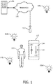
- a user 100 operates a mobile computing device, depicted in the form of a smart phone 102, that is configured to implement selected aspects of the present disclosure. While smart phone 102 will be referenced in various examples described herein, this is not meant to be limiting, and it should be understood that other mobile computing devices, such as tablet computers, laptops, personal digital assistants, and custom remote controls may be configured to control lighting as described herein. Smart phone 102 may include a touch screen display 104, as well as other components that will be discussed below.
- LED-based lighting unit 106 Each may be referred to generically as "LED-based lighting unit 106").
- LED-based lighting unit 106 Each may be referred to generically as "LED-based lighting unit 106"
- Fig. 1 For illustrative purposes. It should be understood that any number of LED-based lighting units may be controlled using mobile devices such as smart phone 102 and techniques described herein.
- LED-based lighting units are referenced in numerous examples described herein, this is not meant to be limiting, and other types of lighting units capable of being controlled and having their lighting properties adjusted may be used instead.
- Each LED-based lighting unit 106 may be configured to be wirelessly controlled by mobile computing devices such as smart phone 102.
- plurality of LED-based lighting units 106a-d may be in network communication with each other and/or a lighting control computing system 108 through one or more networks 110.
- one or more networks 110 may include a wireless network, such as a Wi-Fi network provided by an access point 112.
- the plurality of LED-based lighting units 106a-d may be configured to communicate with each other and/or other computing systems, such as smart phone 102, using other communication technologies, including but not limited to ZigBee, coded light transmissions, RFID, NFC, and so forth.
- an IP bridge may be established between the Wi-Fi network and a dedicated wireless communication technology (e.g., ZigBee) used by plurality of LED-based lighting units 106a-d.
- a dedicated wireless communication technology e.g., ZigBee
- causing one LED-based lighting unit to implement a desired lighting property adjustment may cause other LED-based lighting units in the group to automatically implement or contribute to implementation of the lighting property adjustment.
- Smart phone 102 may be configured to receive, e.g., via one or more user inputs such as touch screen 104, input indicative of a desired lighting property adjustment for a lighting effect.
- a graphical user interface (GUI) 114 is rendered on touch screen 104, and includes two sliders: "BRT” for adjusting brightness; and "HUE” for adjusting a hue.
- GUI graphical user interface
- the lighting effect may be a local lighting effect (e.g., the light in a room or setting) sensed by a light sensor (see Fig. 2 ) associated with smart phone 102.
- Smart phone 102 may be configured to identify one or more LED-based lighting units (e.g., from plurality of LED-based lighting units 106a-d) that contribute to the sensed lighting effect.
- LED-based lighting units 106a and 106b are relatively close to user 100 and smart phone 102, and thus, light they emit may contribute more to a light effect sensed by smart phone 102 than LED-based lighting unit 106d, which is farther from smart phone 102 than LED-based lighting units 106a and 106b.
- LED-based lighting unit 106c is even farther away from smart phone 102, and thus light it emits may contribute even less than light emitted from LED-based lighting units 106a, 106b and 106d.
- smart phone 102 may generate, e.g., for wireless transmission to the one or more contributing LED-based lighting units or to lighting control computing system 108, an instruction configured to cause at least some of the one or more contributing LED-based lighting units to implement the user's desired lighting property adjustment. For instance, smart phone 102 may transmit the instruction over network 110 through access point 112 to lighting control computing system 108. Lighting control computing system 108 may then instruct one or more of plurality of LED-based lighting units 106a-d to implement the desired lighting property adjustment.
- smart phone 102 may additionally or alternatively transmit a coded light signal (e.g., using a camera flash) carrying the generated instruction to plurality of LED-based lighting units 106a-d. If plurality of LED-based lighting units 106a-d are equipped to communicate using Wi-Fi, then smart phone 102 may additionally or alternatively transmit the instruction to plurality of LED-based lighting units 106a-d through access point 112 and network 110.
- a coded light signal e.g., using a camera flash
- smart phone 102 may additionally or alternatively transmit the instruction to plurality of LED-based lighting units 106a-d through access point 112 and network 110.
- smart phone 102 may wirelessly broadcast a preliminary instruction to cause one or more nearby LED-based lighting units to identify themselves to smart phone 102.
- the preliminary instruction may cause one or more LED-based lighting units to briefly illuminate (e.g., at a low intensity) and broadcast coded light signals that identify themselves.
- smart phone 102 may generate this preliminary instruction immediately after receiving the input indicative of the desired lighting property adjustment.
- the LED-based lighting units may instead blink in a predefined and identifying sequence known to smart phone 102. In some cases, the blinks are sufficiently brief to be imperceptible to user 100.
- smart phone 102 may be configured to identify a particular contributing LED-based lighting unit that contributes more to the sensed lighting effect than one or more others of the one or more contributing LED-based lighting units. For instance, smart phone 102 may capture, e.g., using a front or rear facing camera, a digital image of one or more LED-based lighting units. In some embodiments, smart phone 102 may employ a rolling shutter image capture technique. Smart phone 102 may then analyze the captured digital image to determine which LED-based lighting unit is contributing more than others, or which LED-based lighting unit is closest. Smart phone 102 may then tailor an instruction to that highest-contributing LED-based lighting unit that causes it to play a larger role in collective implementation of a desired lighting property adjustment of user 100 than other contributing LED-based lighting units.
- Smart phone 102 may be programmed, e.g., by user 100, with predefined lighting effects that represent preferences of user 100. For example, user 100 may have a particular default light setting that she prefers in a particular room in her house. If the room is dark when user 100 walks in, when she operates smart phone 102 to enable light control inputs (e.g., by opening a lighting control application), smart phone 102 may first generate an instruction configured to cause at least some LED-based lighting units in the room to implement the predefined lighting effect. Then, when user 100 provides input indicative of a desired lighting property adjustment, smart phone 102 may generate an instruction that causes the one or more contributing LED-based light sources in the room to implement the desired lighting property adjustment.
- predefined lighting effects that represent preferences of user 100. For example, user 100 may have a particular default light setting that she prefers in a particular room in her house. If the room is dark when user 100 walks in, when she operates smart phone 102 to enable light control inputs (e.g., by opening a lighting control application), smart phone
- smart phone 102 may be configured to generate the desired lighting property adjustment instruction in a manner that limits which of the one or more contributing LED-based lighting units implements the desired lighting property adjustment. This generation may be based on various data, including but not limited to a social context (e.g., determined from a social networking application executing on smart phone 102), activity of nearby mobile computing devices (e.g., recently or simultaneously used to control a local lighting effect), and so forth. For example, if user 100 is eating dinner in a crowded restaurant with controllable LED-based lighting units, smart phone 102 may only instruct LED-based lighting units at or near a table of user 100 to implement a desired lighting property adjustment.
- a social context e.g., determined from a social networking application executing on smart phone 102
- activity of nearby mobile computing devices e.g., recently or simultaneously used to control a local lighting effect
- smart phone 102 may only instruct LED-based lighting units at or near a table of user 100 to implement a desired lighting property adjustment.
- smart phone 102 may include a controller 220 operably coupled to memory 222. Smart phone 102 may also include a plurality of user inputs 224. User inputs 224 may come in various forms, and may be implemented using any combination of hardware and software. For example, touch screen 104 was mentioned above in reference to Fig. 1 . Controller 220 may be configured to render, on touch screen 104, one or more GUI elements 226a-n. GUI elements 226a-n may come in various forms, including but not limited to the sliders shown in Fig. 1 , wheels that can be rotated to alter a lighting property (e.g., color wheels), checkboxes, buttons, or any other standard GUI input element.
- a lighting property e.g., color wheels
- checkboxes e.g., buttons, or any other standard GUI input element.
- GUI elements 226 may be operable to run macros that cause automatic implementation of predefined lighting preferences. For instance, one button may be operable to cause one or more LED-based lighting units to implement a "concentrating" lighting scheme. Another button may be operable to cause one or more LED-based lighting units to implement a "party” lighting scheme, which could include more festive and/or animated lighting.
- User inputs 224 may include a microphone 228.
- Microphone 228 may be configured to receive a spoken command (e.g., "make more light,” "create romantic light") from user 100.
- Smart phone 102 may be equipped with voice recognition hardware and/or software (not shown) to translate spoken user commands to digital commands configured to cause smart phone 102 to generate desired lighting property adjustment instructions for wireless transmission to one or more LED-based lighting units (e.g., 106a-d).
- user 100 may specify that only local light should be adjusted (e.g., "dim light here”), or that all controllable light in the vicinity should be adjusted (e.g., "dim light”).
- User inputs 224 may include various hardware controls on an exterior of smart phone 102.
- volume up/down buttons 230 may, when smart phone 102 is operating in the context of lighting control, be operated by user 100 to provide desired lighting property adjustments (e.g., turn brightness up/down).
- desired lighting property adjustments e.g., turn brightness up/down.
- a one- or two-dimensional wheel 232 which may nominally be used to adjust volume or move a cursor around touch screen 104, etc., may be requisitioned for lighting control.
- User inputs 224 may include one or more touch-sensitive exterior surfaces 234 of smart phone 102. These exterior surfaces may be rendered touch-sensitive by means of one or more capacitive touch pads, or with other similar techniques, such as swept frequency capacitive sensing. These touch-sensitive exterior surfaces may be located on various parts of the exterior of smart phone 102, such as around its outer rim, on its back, and so forth. For example, in Fig. 3 , a user is shown touching a top edge of smart phone 102, which may cause smart phone 102 to generate a desired lighting property adjustment instruction in a manner that reflects how the user moves her finger along the top.
- smart phone 102 may generate the desired lighting property adjustment instruction to cause one or more LED-based lighting units to turn brightness up. If the user slides her finger in an opposite direction, smart phone 102 may generate the desired lighting property adjustment instruction to cause one or more LED-based lighting units to turn brightness down.
- Other touch-sensitive exterior surfaces of smart phone 102 such as its back surface, sides, or bottom, may be operated in a similar manner.
- user inputs 224 may further include one or more accelerometers 236 (hereinafter referred to in the singular, “accelerometer”). Additionally or alternatively, in various embodiments, user inputs 224 may include one or more gyroscopes 238 (hereinafter referred to in the singular, “gyroscope”). In some embodiments, three gyroscopes 238 may be employed to facilitate three-dimensional gesture recognition. Accelerometer 236 and/or gyroscope 238 may be configured to detect movement of smart phone 102, and provide controller 220 with one or more signals representative of that detected movement. Thus, user 100 may make one or more gestures with smart phone 102, which may cause smart phone 102 to generate an appropriate desired lighting property adjustment instruction.
- Fig. 4 depicts smart phone 102 being tilted from one side to another, which may cause smart phone 102 to generate the desired lighting property adjustment instruction to cause one or more LED-based lighting units to increase/decrease a lighting property.
- Other gestures may cause different lighting changes.
- a shake may cause smart phone 102 to generate the desired lighting property adjustment instruction to cause one or more LED-based lighting units turn on/off, or to create an animated lighting effect.
- a wave may cause an adjustment to lighting intensity. Tapping smart phone 102 may cause one or more LED-based lighting units to turn off or toggle through various predefined lighting effects.
- a camera could capture one or more digital images of a gesture (e.g., made with a user's hand), which controller 220 could recognize, e.g., by matching the captured gesture to a library of potential gestures.
- controller 220 may enable touch screen 104 and/or one or more touch-sensitive surfaces 234 to respond to various types of tactile input to allow user 100 to control lighting.
- user may "double tap" touch screen 104 or another touch sensitive surface 234 to perform some lighting control action.
- user 100 may slide her fingers closer together, farther apart, or in a circle to adjust various lighting properties (e.g., brightness, the size of a lighting effect produced by an LED-based lighting unit, etc.).
- GUI elements 226 may be displayed to guide user 100 through these actions. Later, when user 100 is more comfortable with the interface, fewer or no GUI elements 226 may be rendered.
- mobile devices such as smart phone 102 may be configured to selectively enable the one or more user inputs 224 to receive the input indicative of the desired lighting property adjustment based on a lighting context (also referred to as a "contextual cue") detected by at least one contextual sensor 240 associated with the mobile computing device.
- a lighting context also referred to as a "contextual cue”
- user 100 may avoid having to unlock smart phone 102, locate a lighting control application, open the lighting control application, and in some cases configure the lighting application to control a particular LED-based lighting source.
- smart phone 102 may instantly and automatically enable inputs (e.g., sliders rendered on touch screen 104, touch-sensitive surfaces 234, activated accelerometer 236, etc.) so that user 100 can immediately control lighting.
- inputs e.g., sliders rendered on touch screen 104, touch-sensitive surfaces 234, activated accelerometer 236, etc.
- Contextually-triggered instant access to lighting control may be implemented in various ways.
- all or a portion of a lighting control application may execute on smart phone 102, e.g., as a background process, so that it is able to "awaken" instantly on detection by smart phone 102 of one or more lighting contexts.
- the detected lighting context may be a location of smart phone 102.
- controller 220 may selectively enable one or more user inputs 224 based on a determination of whether smart phone 102 is within a predefined area that is known to offer a controllable lighting infrastructure, or within a predetermined distance of the one or more LED-based lighting units (e.g., 106a-d) that user 100 is authorized to control.
- smart phone 102 may be equipped with a GPS unit 242, and the lighting context may be coordinates provided by GPS unit 242.
- smart phone 102 may rely on other means for determining its location. For instance, in some examples, controller 220 may be configured to determine whether smart phone 102 is within a predefined area or within a predetermined distance of one or more LED-based lighting units based on whether the coordinates provided by GPS unit 242 correspond to an entrance to a building. If user 100 passes through the building's entrance, the last GPS coordinate provided by GPS unit 242 may be at the entrance. Smart phone 102 may presume that user 100 has entered the building, and may then automatically enable one or more user inputs 224 to receive input indicative of a desired lighting property adjustment for one or more LED-based lighting units in the building.
- smart phone 102 may presume that user 100 has left the building, and may disable the previously-enabled user inputs 224.
- contextual sensors 240 of smart phone 102 may include a Wi-Fi interface 244.
- controller 220 may be configured to determine whether the location of smart phone 102 is within the predefined area or within the predetermined distance of the one or more contributing LED-based lighting units based on Wi-Fi fingerprinting and/or triangulation.
- smart phone 102 may deduce its location by virtue of connection to a Wi-Fi base station that the smart phone 102 knows to be in a particular location, such as a user's home.
- Other wireless technologies may similarly be used to determine a location of smart phone 102, including but not limited to Bluetooth, a cellular signal (e.g., through GSM tower triangulation), SiRFusion, GPS pseudolites, and so forth.
- Non-location-based contextual cues may also trigger controller 220 to selectively enable one or more user inputs 224.
- contextual sensors 240 may include a light sensor 246.
- Light sensor 246 may come in various forms, including a digital camera (on a front or back of smart phone 102) and/or a photocell.
- light sensor 246 may sense a local lighting effect (e.g., immediately-observable light), that may in include one or more lighting properties (e.g., brightness, hue, saturation, etc.).
- controller 220 may selectively enable one or more user inputs 224 based on the sensed lighting properties. For example, if the sensed local lighting effect is darker or lighter than predefined preferences of user 100 (e.g., the user walks into a dark room), controller 220 may automatically render a brightness slider on touch screen 104 so that user 100 is instantly able to turn the brightness up or down. Additionally or alternatively, when ambient light drops below a certain threshold, e.g., after sunset, controller 220 may selectively enable one or more user inputs 224 so that user 100 may turn on the lights or turn up brightness.
- a certain threshold e.g., after sunset
- light sensor 246 may be configured to detect a coded light signal carried in light output produced by one or more LED-based lighting units (e.g., one or more of 106a-d). Based on the received coded light, controller 220 may selectively enable one or more user inputs 224. For instance, if the coded light identifies an LED-based lighting unit as one that is "known" by smart phone 102, then smart phone 102 may enable one or more user inputs 224 so that user 100 is able to instantly control that LED-based lighting unit without having to unlock the phone, find and open the lighting control application, etc.
- Contextual sensors 240 of smart phone 102 may include an NFC interface 248.
- smart phone 102 may additionally or alternatively include other radio interfaces, including but not limited to RFID, Bluetooth, etc.
- controller 220 of smart phone 102 may selectively enable one or more user inputs 224 so that user 100 is instantly able to control a lighting property of the one or more LED-based lighting units. For instance, a user walking into her place of employment may be required to provide credentials that authorize the user to enter, e.g., by tapping an NFC-enabled device such as smart phone 102 against an NFC reader.
- controller 220 may automatically enable one or more of user inputs 224 to enable the user to instantly adjust lighting in her office.
- Contextual sensors 240 of smart phone 102 may additionally or alternatively include a proximity sensor 250.
- controller 220 may determine, based on information provided by proximity sensor 250, that smart phone 102 is in a hand of user 100, or at least is no longer in the user's pocket. In response, controller 220 may selectively enable one or more user inputs 224 to receive input indicative of a desired lighting property adjustment.
- Contextual sensors 240 of smart phone 102 may include accelerometer 236 and/or gyroscope 238.
- accelerometer 236 and/or gyroscope 238 may detect that user 100 has made a particular two-dimensional or three-dimensional gesture with smart phone 102 (e.g., a motion to remove smart phone 102 from a pocket, a predefined gesture, etc.).
- controller 220 may selectively enable one or more user inputs 224 to enable user 100 to provide input indicative of a desired lighting property adjustment.
- Contextual sensors 240 of smart phone 102 may include information from one or more social networks 254 of which user 100 is a member. For instance, if user 100 operates a locally-installed social network client to update her social networking status to "relaxing," then controller 220 may selectively enable one or more user inputs 224 so that user 100 is instantly able to adjust nearby lighting to have more relaxing lighting properties.
- Contextual sensors 240 of smart phone 102 may include a calendar 256. For example, if user 100 is scheduled to arrive home at 5:30, controller 220 may selectively enable one or more user inputs 224 at 5:30 so that user 100 can adjust lighting immediately when she walks in the door.
- Contextual sensors 240 of smart phone 102 may include one or more wearable devices 258.
- smart phone 102 may often be in the user's pocket, in which case it would not have line of sight with an LED-based lighting unit to transmit or receive, e.g., light coded signals.
- Wearable device 258 may detect various contextual cues and send indication of those detected cues to smart phone 102.
- wearable device 258 may be considered a "personal" device, and may be used as a key that permits controller 220 to enable more user inputs 224 than might be possible without.
- Lighting contexts may come in the form of receipt, at one or more user inputs 224, of other predefined inputs and/or predefined sequences of inputs.
- user 100 could perform an unusual gesture with smart phone 102 while locked that causes one or more GUI elements 226a-n to be rendered on touch screen 104, without unlocking smart phone 102.
- user 100 could perform a custom gesture on a touch-sensitive exterior surface of smart phone 102, grip smart phone 102 in a particular manner, press some combination of keys simultaneously (e.g., volume up and down at the same time), manipulate a light application icon on a home "locked" screen (similar to a camera or telephone icon on existing smart phones), and so forth.
- controller 220 may cause controller 220 to selectively enable one or more user inputs 224 to receive input indicative of a desired lighting property adjustment without unlocking smart phone 102.
- one or more of these contexts may cause controller 220 to evoke an initial or pre-defined lighting effect.
- User inputs 224 may be selectively enabled in various ways in response to open or more contextual cues. For example, a first of GUI elements 226a-n may be enabled (e.g., rendered on touchscreen 104) in response to a determination that smart phone 102 is sufficiently proximate to LED-based lighting unit 106a, and a second of GUI elements 226a-n may be enabled in response to a determination that smart phone 102 is sufficiently proximate to LED-based lighting unit 106d. Additionally or alternatively, more and more GUI elements 226a-n may be progressively rendered on touch screen 104 as multiple contextual cues in combination or sequence are detected.
- a first GUI element 226 may be rendered to control lighting near the parking spot and/or in the lawn.
- a predetermining lighting effect may also be rendered by LED-based lighting units near the parking spot and/or in the yard, so that user 100 can find her way into the house.
- More GUI elements 226 may be added as user 100 walks into the house and smart phone 102 detects coded light signals from various lighting units.
- controller 220 may enable only sufficient user inputs 224 of smart phone 102 to provide user 100 with rudimentary control of lighting properties of LED-based lighting unit 106a (e.g., its brightness). For instance, controller 220 may render a single brightness slider on touch screen 104.
- controller 220 may render controls on touch screen 104 that allow user 100 to adjust other lighting properties (e.g., hue, saturation, etc.) of LED-based lighting unit 106a.
- one or more LED-based lighting units may be "commissioned" by smart phone 102 so that smart phone 102 is able to identify and control lighting properties output by those lighting units later.
- a user may commission an LED-based lighting unit by enabling a coded light signal emitted by the LED-based lighting unit to be received by light sensor 246.
- the coded light signal may contain a lighting unit identifier and/or location associated with the LED-based lighting unit.
- Controller 220 may store this information in memory 222.
- smart phone 102 itself may determine the location of the LED-based lighting unit, e.g., using its own GPS unit 242 or other means described above, such as Wi-Fi fingerprinting.
- Controller 220 may render a GUI element 226 on touch screen 104 when user 100 carries smart phone 102 into a space that includes one or more lighting units that are controllable using mobile computing devices. This GUI element 226 may provide user 100 with an opportunity to commission one or more local lighting units so that user 100 can easily control them next time user 100 is in the area. Controller 220 may render this GUI element 226 after user 100 opens a lighting control application. In other embodiments, controller 220 may render this GUI element 226 automatically, e.g., on detection of one or more lighting contexts.
- the commissioning step may be skipped where an LED-based lighting unit broadcasts its coordinates and/or identifying information, e.g., using coded light or on a Wi-Fi network.
- a mobile computing device such as smart phone 102 may enable one or more user inputs 224 to receive input indicative of a desired lighting property adjustment, even if smart phone 102 has not previously encountered the LED-based lighting units in question.
- Mobile computing devices such as smart phone 102 may be configured to monitor a local lighting effect, e.g., using light sensor 246, and to adjust lighting and/or selectively enable or disable user inputs 224 based on this feedback.
- smart phone 102 may estimate a size of a lighting effect and/or an implemented lighting property adjustment, and may calibrate, e.g., in real time, additional lighting property adjustments to be made to each controlled, contributing LED-based lighting unit.
- Fig. 6 depicts an example method 600 that may be implemented by mobile computing devices such as smart phone 102.
- a lighting context may be detected, e.g., by one or more contextual sensors 240.
- one or more user inputs 224 may be selectively enabled, e.g., by controller 220, based on the detected lighting context.
- controller 220 may render on touch screen 104 a slider or other GUI element 226 that is operable by a user to adjust a lighting property of light produced by an LED-based lighting unit that contributes to the locally-sensed lighting effect.
- input indicative of a desired lighting property adjustment may be received, e.g., at the enabled one or more user inputs 224 from user 100.
- a preliminary instruction configured to cause one or more LED-based lighting units (e.g., 106a-d) to identify themselves, e.g., to smart phone 102, may be transmitted by smart phone 102 to one or more LED-based lighting units.
- an instruction configured to cause one or more LED-based lighting units (e.g., 106a-d) to output light in a manner such that a predefined lighting effect is achieved, may be transmitted by smart phone 102 to one or more LED-based lighting units. This predefined lighting effect may in some embodiments serve as a baseline to which lighting property adjustments are applied.
- a local lighting effect may be sensed, e.g., by light sensor 246.
- LED-based lighting units e.g., 106a-d
- Controller 220 may identify the contributing LED-based lighting units using various data, including but not limited to one or more lighting properties (e.g., hue, brightness, saturation, a coded light signal, etc.) of light emitted by one or more LED-based lighting units.
- an instruction configured to cause at least some of the contributing LED-based lighting units to implement the desired lighting property adjustment received at block 606 may be generated, e.g., by controller 220.
- the instruction generated at block 616 may be wirelessly transmitted, e.g., by controller 220 using coded light, Wi-Fi, ZigBee, RFID, Bluetooth, etc., to one or more contributing LED-based lighting units.
Description
- The present invention is directed generally to lighting control. More particularly, various inventive methods, apparatus, systems and computer-readable media disclosed herein relate to facilitating control of one or more LED-based lighting units using various user inputs of a mobile computing device.
- Digital lighting technologies, i.e. illumination based on semiconductor light sources, such as light-emitting diodes (LEDs), offer a viable alternative to traditional fluorescent, HID, and incandescent lamps. Functional advantages and benefits of LEDs include high energy conversion and optical efficiency, durability, lower operating costs, and many others. Recent advances in LED technology have provided efficient and robust full-spectrum lighting sources that enable a variety of lighting effects in many applications. Some of the fixtures embodying these sources feature a lighting module, including one or more LEDs capable of producing different colors, e.g. red, green, and blue, as well as a processor for independently controlling the output of the LEDs in order to generate a variety of colors and color-changing lighting effects.
- Lighting units, such as LED-based lighting units, may be controlled by mobile computing devices such as smart phones or tablets. For example, a user may operate a graphical user interface (GUI) to select and control various lighting units in a building or room using her smart phone. In some instances, it may be desirable to enable such a user to quickly and easily control only lighting units in the immediate area around her, e.g., those lighting units that actually affect a lighting effect consumed by the user. Requiring the user to operate the GUI to select these local lighting units adds an additional step for the user, who may simply want to create more or less light at her current location quickly and easily.
- On a mobile device such as a smart phone or tablet, accessing applications, including lighting control applications, may be cumbersome. The mobile device may first need to be unlocked (in some cases requiring a password) and/or otherwise "awakened." Then, a user may be required to find and open the lighting control application, and may even have to configure the lighting control application manually to be able to control a particular lighting unit. These steps may be more complex and cumbersome than simply locating and adjusting manual lighting controls associated with the lighting units. Some mobile computing devices include, on lock screens, quick launch icons for commonly-used and/or low risk applications. These icons may be actuated (e.g., dragged upwards on a touch screen) to initiate the application without having to unlock the touch screen. However, these icons still require at least some user interaction.
-
US Patent 8,248,467, dated August 21, 2013 , is directed to a light positioning system using digital pulse recognition;US Patent Application Publication No. 2009/0239587, dated September 24, 2009 , is directed to a system and method for appliance control via a personal communication or entertainment device;WO 2010/122440, dated October 28, 2010 , is directed to systems and apparatuses for light-based social communications;WO 2012/143814, dated October 26, 2012 , is directed to an outdoor lighting network optimization system;WO 2013/085600, dated June 13, 2013 , is directed to gesture-based lighting controls; andWO 2011/051865, dated May 5, 2011 , is directed to the commissioning of coded light sources. These documents provide some relevant background discussions in the general technical field of the present application. - Thus, there is a need in the art to provide systems, methods, apparatus and computer-readable media that make it easier and/or more convenient to implement a lighting property adjustment at lighting units that affect local lighting effect consumed by a user. There is also a need in the art to make it easier and/or more convenient to access user inputs for controlling lighting units.
- The present disclosure is directed to a mobile computing device according to claim 1 and a computer-implemented method for lighting control according to claim 6. More particularly, various inventive computer-readable media (transitory and non-transitory), methods, systems and apparatus for facilitating lighting control of one or more lighting units are provided. For example, in one embodiment, one or more lighting units that contribute to a sensed lighting effect may be identified in response to receipt of input indicative of a desired lighting property adjustment, and the one or more contributing lighting units may be instructed to implement the desired lighting property adjustment. As an additional example, one or more user inputs may be selectively enabled to receive the input indicative of the desired lighting property adjustment, e.g., in response to detection of a lighting context.
- Generally, in one aspect, the invention relates to a mobile computing device that includes a light sensor, one or more user inputs, and a controller. The controller may be operably coupled to the light sensor and the one or more user inputs, and may be configured to: receive, via the one or more user inputs, input indicative of a desired lighting property adjustment for a lighting effect sensed by the light sensor; identify one or more LED-based lighting units (106a-d) that contribute to the sensed lighting effect, wherein the controller is configured to identify the one or more contributing LED-based lighting units based on one or more lighting properties of light output of the one or more contributing LED-based lighting units that are detected by the light sensor; identify a first of the contributing LED-based lighting units that contributes more to the sensed lighting effect than at least one other LED-based lighting unit, based on one or more lighting properties of light output of the one or more contributing LED-based lighting units that is detected by the light sensor and generate, for wireless transmission to the one or more contributing LED-based lighting units except for the first of the contributing LED-based lighting units, an instruction configured to cause at least some of the one or more contributing LED-based lighting units to implement the desired lighting property adjustment, and for wireless transmission to the first of the contributing LED-based lighting units, a tailored instruction to cause it to play a larger role in collective implementation of a desired lighting property adjustment than at least one other contributing LED-based lighting unit.
- In one embodiment, the controller may be configured to generate, for wireless transmission to one or more nearby LED-based lighting units in response to receipt of the input indicative of the desired lighting property adjustment, a preliminary instruction for the one or more nearby LED-based lighting units to transmit coded light signals to identify themselves to the mobile computing device.
- The controller is configured to identify the one or more contributing LED-based lighting units based on light output of the one or more contributing LED-based lighting units that is detected by the light sensor. In various embodiments, the controller may be configured to identify the one or more contributing LED-based lighting units based on a coded light signal carried in the detected light output of the one or more contributing LED-based lighting units.
- It is disclosed that the controller may be further configured to identify a first of the contributing LED-based lighting units that contributes more to the sensed lighting effect than one or more others of the one or more contributing LED-based lighting units. In one embodiment, the controller may be configured to generate, for wireless transmission to the one or more contributing LED-based lighting units in response to receipt of the input indicative of the desired lighting property adjustment, an instruction configured to cause at least some of the one or more contributing LED-based lighting units to implement a predetermined lighting effect. In one embodiment, the controller may be configured to generate the instruction to limit which of the one or more contributing LED-based lighting units implements the desired lighting property adjustment based on activity of other mobile computing devices nearby.
- The mobile computing device may include at least one contextual sensor. The controller may be further configured to selectively enable the one or more user inputs to receive the input indicative of the desired lighting property adjustment based on a lighting context detected by the at least one contextual sensor. In various versions, the lighting context may include a location of the mobile computing device. The controller may be configured to selectively enable the one or more user inputs based on a determination of whether the location is within a predefined area or within a predetermined distance of the one or more contributing LED-based lighting units.
- In various versions, the at least one contextual sensor may be a GPS unit, and the lighting context may include coordinates provided by the GPS unit. In various versions, the controller may be configured to determine whether the location is within the predefined area or within the predetermined distance of the one or more contributing LED-based lighting units based on whether the coordinates provided by the GPS unit correspond to an entrance to a building.
- In various versions, the at least one contextual sensor may include a Wi-Fi interface, and the controller may be configured to determine whether the location is within the predefined area or within the predetermined distance of the one or more contributing LED-based lighting units based on Wi-Fi fingerprinting.
- Also, the light sensor may be the at least one contextual sensor, and the lighting context may include a coded light signal carried in light output produced by the one or more contributing LED-based lighting units. In various versions, the mobile computing device may include a touch screen. Selectively enabling the one or more user inputs may include selective rendition of one or more aspects of a user interface on the touch screen.
- In various versions, the at least one contextual sensor may include a Wi-Fi interface. The lighting context may include connection, by the mobile computing device via the Wi-Fi interface, with a Wi-Fi base station.
- Further disclosed is a mobile computing device that includes at least one contextual sensor; one or more user inputs; and a controller operably coupled to the at least one contextual sensor and the one or more user inputs. The controller may be configured to: selectively enable the one or more user inputs to receive input indicative of a desired lighting property adjustment for light output produced by one or more LED-based lighting units, based on a lighting context detected by the at least one contextual sensor; and generate, for wireless transmission to the one or more LED-based lighting units in response to receipt at the one or more inputs of the desired lighting property adjustment, an instruction configured to cause at least some of the one or more LED-based lighting units to implement the desired lighting property adjustment.
- The lighting context may include a location of the mobile computing device. The controller may be configured to selectively enable the one or more user inputs based on a determination of whether the location is within a predefined area or within a predetermined distance of the one or more LED-based lighting units.
- The at least one contextual sensor may include a GPS unit, and the lighting context may include coordinates provided by the GPS unit. In various versions, the controller may be further configured to determine whether the location is within the predefined area or within the predetermined distance of the one or more LED-based lighting units based on whether the coordinates provided by the GPS unit correspond to an entrance to a building.
- The at least one contextual sensor may include a Wi-Fi interface. The controller may be configured to determine whether the location is within the predefined area or within the predetermined distance of the one or more LED-based lighting units based on Wi-Fi fingerprinting.
- The at least one contextual sensor may include a Wi-Fi interface, and the lighting context may include connection, by the mobile computing device via the Wi-Fi interface, with a Wi-Fi base station.
- The light sensor may be the at least one contextual sensor, and the lighting context may include a coded light signal carried in light output produced by the one or more LED-based lighting units.
- It is disclosed that the at least one contextual sensor may include an NFC interface, and the lighting context may include authorization received at the NFC interface to control a lighting property of the one or more LED-based lighting units. It is further disclosed that the lighting context may include a determination that the mobile computing device is in a hand of a user.
- The light sensor may include the at least one contextual sensor, and the lighting context may include a lighting property of the sensed lighting effect detected by the light sensor. It is disclosed that the detected lighting property of the sensed lighting effect may include a brightness, and the controller may be configured to selectively enable the one or more user inputs based on whether the detected brightness is above a first predetermined threshold or below a second predetermined threshold.
- The mobile computing device may include a touch screen. Selectively enabling the one or more user inputs may include selective rendition of one or more aspects of a user interface on the touch screen. It is disclosed that the mobile computing device may include a microphone. Selectively enabling the one or more user inputs may include activation of the microphone to receive a spoken command. It is further disclosed that the mobile computing device may include an accelerometer. Selectively enabling the one or more user inputs may include activation of the accelerometer to detect a user gesture.
- It is disclosed that the lighting context may include a sequence of contextual cues and the controller may be configured to selectively enable one or more aspects of the one or more user inputs based on the detected sequence. In various embodiments, the controller may be configured to generate, for transmission to one or more nearby LED-based lighting units in response to receipt of the input indicative of the desired lighting property adjustment, a preliminary instruction for the one or more nearby LED-based lighting units to transmit coded light signals that identify themselves to the mobile computing device.
- The at least one contextual sensor includes a light sensor configured to sense a lighting effect. The controller may be configured to identify one or more LED-based lighting units that contribute to the sensed lighting effect based on light output of the one or more LED-based lighting units that is detected by the light sensor.
- Methods, systems and computer-readable media (transitory and non-transitory) may also be provided.
- For example, in yet another aspect, the invention relates to a computer-implemented method for lighting control, comprising the steps of: receiving (606), by a mobile computing device, input indicative of a desired lighting property adjustment for a lighting effect sensed by a light sensor (246) of the mobile computing device; identifying (614), by the mobile computing device, one or more LED-based lighting units (106a-d) that contribute to the sensed lighting effect, the one or more contributing LED-based lighting units based on one or more lighting properties of light output of the one or more contributing LED-based lighting units that are detected by the light sensor; identifying, by the mobile computing device, a first of the contributing LED-based lighting units that contributes more to the sensed lighting effect than at least one other LED-based lighting unit, based on one or more lighting properties of light output of the one or more contributing LED-based lighting units, that is detected by the light sensor; and generating (616), by the mobile computing device for wireless transmission to the one or more contributing LED-based lighting units except for the first of the contributing LED-based lighting units, an instruction configured to cause at least some of the one or more contributing LED-based lighting units to implement the desired lighting property adjustment, and for wireless transmission to the first of the contributing LED-based lighting units, a tailored instruction to cause it to play a larger role in collective implementation of a desired lighting property adjustment than at least one other contributing LED-based lighting unit.
- It is disclosed that the mobile computing device may be configured to identify the one or more contributing LED-based lighting units based on light output of the one or more contributing LED-based lighting units that is detected by the light According to the present invention, the mobile computing device may be configured to identify the one or more contributing LED-based lighting units based on a coded light signal carried in the detected light output of the one or more contributing LED-based lighting units.
- In one embodiment, the instruction configured to cause at least some of the one or more contributing LED-based lighting units to implement the desired lighting property adjustment includes an instruction to limit which of the one or more contributing LED-based lighting units implements the desired lighting property adjustment based on activity of other mobile computing devices nearby.
- It is disclosed that the method may include detecting, by at least one contextual sensor, a lighting context and selectively enabling one or more user inputs indicative of the desired lighting property adjustment based on the lighting context. The lighting context may include a location of the mobile computing device, and the mobile computing device may be configured to selectively enable the one or more user inputs based on a determination of whether the location is within a predefined area or within a predetermined distance of the one or more contributing LED-based lighting units. In one example, the at least one contextual sensor includes a GPS unit, and the lighting context comprises coordinates provided by the GPS unit. The mobile computing device may be further configured to determine whether the location is within the predefined area or within the predetermined distance of the one or more contributing LED-based lighting units based on whether the coordinates provided by the GPS unit correspond to an entrance to a building. In some versions, the at least one contextual sensor includes a Wi-Fi interface, and the mobile computing device is configured to determine whether the location is within the predefined area or within the predetermined distance of the one or more contributing LED-based lighting units based on Wi-Fi fingerprinting. Also, the light sensor may include the at least one contextual sensor, and the lighting context may include a coded light signal carried in light output produced by the one or more contributing LED-based lighting units. Further, the at least one contextual sensor may include a Wi-Fi interface, and the lighting context may include connection, by the mobile computing device via the Wi-Fi interface, with a Wi-Fi base station. The lighting context may also include a determination that the mobile computing device is in a hand of a user.
- As used herein for purposes of the present disclosure, the term "LED" should be understood to include any electroluminescent diode or other type of carrier injection/junction-based system that is capable of generating radiation in response to an electric signal. Thus, the term LED includes, but is not limited to, various semiconductor-based structures that emit light in response to current, light emitting polymers, organic light emitting diodes (OLEDs), electroluminescent strips, and the like. In particular, the term LED refers to light emitting diodes of all types (including semi-conductor and organic light emitting diodes) that may be configured to generate radiation in one or more of the infrared spectrum, ultraviolet spectrum, and various portions of the visible spectrum (generally including radiation wavelengths from approximately 400 nanometers to approximately 700 nanometers). For example, one implementation of an LED configured to generate essentially white light (e.g., a white LED) may include a number of dies which respectively emit different spectra of electroluminescence that, in combination, mix to form essentially white light. In another implementation, a white light LED may be associated with a phosphor material that converts electroluminescence having a first spectrum to a different second spectrum. In one example of this implementation, electroluminescence having a relatively short wavelength and narrow bandwidth spectrum "pumps" the phosphor material, which in turn radiates longer wavelength radiation having a somewhat broader spectrum.
- It should also be understood that the term LED does not limit the physical and/or electrical package type of an LED. For example, as discussed above, an LED may refer to a single light emitting device having multiple dies that are configured to respectively emit different spectra of radiation (e.g., that may or may not be individually controllable). Also, an LED may be associated with a phosphor that is considered as an integral part of the LED (e.g., some types of white LEDs
The term "light source" should be understood to refer to any one or more of a variety of radiation sources, including, but not limited to, LED-based sources (including one or more LEDs as defined above). A given light source may be configured to generate electromagnetic radiation within the visible spectrum, outside the visible spectrum, or a combination of both. Hence, the terms "light" and "radiation" are used interchangeably herein. Additionally, a light source may include as an integral component one or more filters (e.g., color filters), lenses, or other optical components. Also, it should be understood that light sources may be configured for a variety of applications, including, but not limited to, indication, display, and/or illumination. An "illumination source" is a light source that is particularly configured to generate radiation having a sufficient intensity to effectively illuminate an interior or exterior space. In this context, "sufficient intensity" refers to sufficient radiant power in the visible spectrum generated in the space or environment (the unit "lumens" often is employed to represent the total light output from a light source in all directions, in terms of radiant power or "luminous flux") to provide ambient illumination (i.e., light that may be perceived indirectly and that may be, for example, reflected off of one or more of a variety of intervening surfaces before being perceived in whole or in part). - For purposes of this disclosure, the term "color" is used interchangeably with the term "spectrum." However, the term "color" generally is used to refer primarily to a property of radiation that is perceivable by an observer (although this usage is not intended to limit the scope of this term). Accordingly, the terms "different colors" implicitly refer to multiple spectra having different wavelength components and/or bandwidths. It also should be appreciated that the term "color" may be used in connection with both white and non-white light.
- The term "color temperature" generally is used herein in connection with white light, although this usage is not intended to limit the scope of this term. Color temperature essentially refers to a particular color content or shade (e.g., reddish, bluish) of white light. The color temperature of a given radiation sample conventionally is characterized according to the temperature in degrees Kelvin (K) of a black body radiator that radiates essentially the same spectrum as the radiation sample in question. Black body radiator color temperatures generally fall within a range of from approximately 700 degrees K (typically considered the first visible to the human eye) to over 10,000 degrees K; white light generally is perceived at color temperatures above 1500-2000 degrees K.
- The term "lighting fixture" is used herein to refer to an implementation or arrangement of one or more lighting units in a particular form factor, assembly, or package. The term "lighting unit" is used herein to refer to an apparatus including one or more light sources of same or different types. A given lighting unit may have any one of a variety of mounting arrangements for the light source(s), enclosure/housing arrangements and shapes, and/or electrical and mechanical connection configurations. Additionally, a given lighting unit optionally may be associated with (e.g., include, be coupled to and/or packaged together with) various other components (e.g., control circuitry) relating to the operation of the light source(s). An "LED-based lighting unit" refers to a lighting unit that includes one or more LED-based light sources as discussed above, alone or in combination with other non LED-based light sources.
- The term "controller" is used herein generally to describe various apparatus relating to, among other functions, the operation of one or more light sources. A controller can be implemented in numerous ways (e.g., such as with dedicated hardware) to perform various functions discussed herein. A "processor" is one example of a controller which employs one or more microprocessors that may be programmed using software (e.g., microcode) to perform various functions discussed herein. A controller may be implemented with or without employing a processor, and also may be implemented as a combination of dedicated hardware to perform some functions and a processor (e.g., one or more programmed microprocessors and associated circuitry) to perform other functions. Examples of controller components that may be employed in various embodiments of the present disclosure include, but are not limited to, conventional microprocessors, application specific integrated circuits (ASICs), and field-programmable gate arrays (FPGAs).
- In various implementations, a processor or controller may be associated with one or more storage media (generically referred to herein as "memory," e.g., volatile and non-volatile computer memory such as RAM, PROM, EPROM, and EEPROM, floppy disks, compact disks, optical disks, magnetic tape, etc.). In some implementations, the storage media may be encoded with one or more programs that, when executed on one or more processors and/or controllers, perform at least some of the functions discussed herein. Various storage media may be fixed within a processor or controller or may be transportable, such that the one or more programs stored thereon can be loaded into a processor or controller so as to implement various aspects of the present invention discussed herein. The terms "program" or "computer program" are used herein in a generic sense to refer to any type of computer code (e.g., software or microcode) that can be employed to program one or more processors or controllers.
- The term "network" as used herein refers to any interconnection of two or more devices (including controllers or processors) that facilitates the transport of information (e.g. for device control, data storage, data exchange, etc.) between any two or more devices and/or among multiple devices coupled to the network. As should be readily appreciated, various implementations of networks suitable for interconnecting multiple devices may include any of a variety of network topologies and employ any of a variety of communication protocols. Additionally, in various networks according to the present disclosure, any one connection between two devices may represent a dedicated connection between the two systems, or alternatively a non-dedicated connection. In addition to carrying information intended for the two devices, such a non-dedicated connection may carry information not necessarily intended for either of the two devices (e.g., an open network connection). Furthermore, it should be readily appreciated that various networks of devices as discussed herein may employ one or more wireless, wire/cable, and/or fiber optic links to facilitate information transport throughout the network.
- The term "user interface" as used herein refers to an interface between a human user or operator and one or more devices that enables communication between the user and the device(s).
- It should also be appreciated that terminology explicitly employed herein should be accorded a meaning most consistent with the particular concepts disclosed herein.
- In the drawings, like reference characters generally refer to the same parts throughout the different views. Also, the drawings are not necessarily to scale, emphasis instead generally being placed upon illustrating the principles of the invention.
-
Fig. 1 schematically illustrates an example mobile computing device in the form of a smart phone, configured with selected aspects of the present disclosure, interacting with a plurality of LED-based lighting units, in accordance with one embodiment. -
Fig. 2 schematically depicts example components of a smart phone configured with selected aspects of the present disclosure, in accordance with one embodiment. -
Figs. 3-5 depict examples of how a user may interact with a smart phone to control lighting. -
Fig. 6 depicts an example method that may be implemented by a mobile computing device configured with selected aspects of the present disclosure, in accordance with one embodiment. - Lighting units such as LED-based lighting units may be controlled by mobile computing devices, such as smart phones or tablets. For example, a user may be able to select and control various lighting units in a building or room using her smart phone. In some instances it may be desirable to enable such a user to quickly and easily control only lighting units in the immediate area around her, e.g., those lighting units that actually contribute to a lighting effect consumed by the user. Requiring the user to operate a user interface to select these local light units adds an additional step for the user, who may simply want to create more or less light generally at her current location quickly and easily.
- On a mobile device such as a smart phone or tablet, accessing applications, including lighting control applications, may be cumbersome. The mobile device may first need to be unlocked and/or otherwise "awakened." Then, a user may be required to locate the lighting control application. These steps may be more complex and cumbersome than simply locating and adjusting manual lighting controls associated with the lighting units.
- Thus, Applicants have recognized and appreciated that it would be beneficial to make it easier and/or more convenient to implement a lighting property adjustment at lighting units that affect local lighting effect consumed by a user, and/or to access user inputs for controlling lighting units. In view of the foregoing, various embodiments and implementations of the present invention are directed to enabling implementation of a desired lighting property adjustment on light sources that contribute to an observed lighting effect using a mobile device, as well as selectively enabling one or more user inputs on the mobile device based on a detected lighting context.
- Referring to
Fig. 1 , auser 100 operates a mobile computing device, depicted in the form of asmart phone 102, that is configured to implement selected aspects of the present disclosure. Whilesmart phone 102 will be referenced in various examples described herein, this is not meant to be limiting, and it should be understood that other mobile computing devices, such as tablet computers, laptops, personal digital assistants, and custom remote controls may be configured to control lighting as described herein.Smart phone 102 may include atouch screen display 104, as well as other components that will be discussed below. -
User 100 is shown at various proximities from a plurality of LED-based lighting units, 106a-106d (each may be referred to generically as "LED-based lighting unit 106"). Four LED-based lighting units are depicted inFig. 1 for illustrative purposes. It should be understood that any number of LED-based lighting units may be controlled using mobile devices such assmart phone 102 and techniques described herein. Moreover, while "LED-based lighting units" are referenced in numerous examples described herein, this is not meant to be limiting, and other types of lighting units capable of being controlled and having their lighting properties adjusted may be used instead. - Each LED-based lighting unit 106 may be configured to be wirelessly controlled by mobile computing devices such as
smart phone 102. For example, plurality of LED-basedlighting units 106a-d may be in network communication with each other and/or a lightingcontrol computing system 108 through one ormore networks 110. In some embodiments, one ormore networks 110 may include a wireless network, such as a Wi-Fi network provided by anaccess point 112. The plurality of LED-basedlighting units 106a-d may be configured to communicate with each other and/or other computing systems, such assmart phone 102, using other communication technologies, including but not limited to ZigBee, coded light transmissions, RFID, NFC, and so forth. In some embodiments where a Wi-Fi network is present but plurality of LED-basedlighting units 106a-d are not Wi-Fi-compatible, an IP bridge may be established between the Wi-Fi network and a dedicated wireless communication technology (e.g., ZigBee) used by plurality of LED-basedlighting units 106a-d. In some examples where multiple LED-based lighting units are part of a group, causing one LED-based lighting unit to implement a desired lighting property adjustment may cause other LED-based lighting units in the group to automatically implement or contribute to implementation of the lighting property adjustment. -
Smart phone 102 may be configured to receive, e.g., via one or more user inputs such astouch screen 104, input indicative of a desired lighting property adjustment for a lighting effect. For example, inFig. 1 , a graphical user interface (GUI) 114 is rendered ontouch screen 104, and includes two sliders: "BRT" for adjusting brightness; and "HUE" for adjusting a hue. Various other user inputs that may be used to receive input indicative of desired lighting adjustments will be described below with reference toFigs. 2-5 . - The lighting effect may be a local lighting effect (e.g., the light in a room or setting) sensed by a light sensor (see
Fig. 2 ) associated withsmart phone 102.Smart phone 102 may be configured to identify one or more LED-based lighting units (e.g., from plurality of LED-basedlighting units 106a-d) that contribute to the sensed lighting effect. For instance, inFig. 1 , LED-basedlighting units user 100 andsmart phone 102, and thus, light they emit may contribute more to a light effect sensed bysmart phone 102 than LED-basedlighting unit 106d, which is farther fromsmart phone 102 than LED-basedlighting units lighting unit 106c is even farther away fromsmart phone 102, and thus light it emits may contribute even less than light emitted from LED-basedlighting units - In one embodiment,
smart phone 102 may generate, e.g., for wireless transmission to the one or more contributing LED-based lighting units or to lightingcontrol computing system 108, an instruction configured to cause at least some of the one or more contributing LED-based lighting units to implement the user's desired lighting property adjustment. For instance,smart phone 102 may transmit the instruction overnetwork 110 throughaccess point 112 to lightingcontrol computing system 108. Lightingcontrol computing system 108 may then instruct one or more of plurality of LED-basedlighting units 106a-d to implement the desired lighting property adjustment. If plurality of LED-basedlighting units 106a-d are equipped to receive coded light signals, thensmart phone 102 may additionally or alternatively transmit a coded light signal (e.g., using a camera flash) carrying the generated instruction to plurality of LED-basedlighting units 106a-d. If plurality of LED-basedlighting units 106a-d are equipped to communicate using Wi-Fi, thensmart phone 102 may additionally or alternatively transmit the instruction to plurality of LED-basedlighting units 106a-d throughaccess point 112 andnetwork 110. - In order to identify the one or more contributing LED-based lighting units,
smart phone 102 may wirelessly broadcast a preliminary instruction to cause one or more nearby LED-based lighting units to identify themselves tosmart phone 102. For instance, in one embodiment, the preliminary instruction may cause one or more LED-based lighting units to briefly illuminate (e.g., at a low intensity) and broadcast coded light signals that identify themselves. In various embodiments,smart phone 102 may generate this preliminary instruction immediately after receiving the input indicative of the desired lighting property adjustment. In embodiments in which LED-based lighting units are not equipped to transmit coded light signals, the LED-based lighting units may instead blink in a predefined and identifying sequence known tosmart phone 102. In some cases, the blinks are sufficiently brief to be imperceptible touser 100. - In one embodiment,
smart phone 102 may be configured to identify a particular contributing LED-based lighting unit that contributes more to the sensed lighting effect than one or more others of the one or more contributing LED-based lighting units. For instance,smart phone 102 may capture, e.g., using a front or rear facing camera, a digital image of one or more LED-based lighting units. In some embodiments,smart phone 102 may employ a rolling shutter image capture technique.Smart phone 102 may then analyze the captured digital image to determine which LED-based lighting unit is contributing more than others, or which LED-based lighting unit is closest.Smart phone 102 may then tailor an instruction to that highest-contributing LED-based lighting unit that causes it to play a larger role in collective implementation of a desired lighting property adjustment ofuser 100 than other contributing LED-based lighting units. -
Smart phone 102 may be programmed, e.g., byuser 100, with predefined lighting effects that represent preferences ofuser 100. For example,user 100 may have a particular default light setting that she prefers in a particular room in her house. If the room is dark whenuser 100 walks in, when she operatessmart phone 102 to enable light control inputs (e.g., by opening a lighting control application),smart phone 102 may first generate an instruction configured to cause at least some LED-based lighting units in the room to implement the predefined lighting effect. Then, whenuser 100 provides input indicative of a desired lighting property adjustment,smart phone 102 may generate an instruction that causes the one or more contributing LED-based light sources in the room to implement the desired lighting property adjustment. - Confusion may arise if multiple mobile computing devices such as
smart phone 102 are being operated simultaneously to control an area's lighting. Accordingly, in one embodiment,smart phone 102 may be configured to generate the desired lighting property adjustment instruction in a manner that limits which of the one or more contributing LED-based lighting units implements the desired lighting property adjustment. This generation may be based on various data, including but not limited to a social context (e.g., determined from a social networking application executing on smart phone 102), activity of nearby mobile computing devices (e.g., recently or simultaneously used to control a local lighting effect), and so forth. For example, ifuser 100 is eating dinner in a crowded restaurant with controllable LED-based lighting units,smart phone 102 may only instruct LED-based lighting units at or near a table ofuser 100 to implement a desired lighting property adjustment. - Referring to
Fig. 2 ,smart phone 102 may include acontroller 220 operably coupled tomemory 222.Smart phone 102 may also include a plurality of user inputs 224. User inputs 224 may come in various forms, and may be implemented using any combination of hardware and software. For example,touch screen 104 was mentioned above in reference toFig. 1 .Controller 220 may be configured to render, ontouch screen 104, one ormore GUI elements 226a-n.GUI elements 226a-n may come in various forms, including but not limited to the sliders shown inFig. 1 , wheels that can be rotated to alter a lighting property (e.g., color wheels), checkboxes, buttons, or any other standard GUI input element. In some embodiments, GUI elements 226 may be operable to run macros that cause automatic implementation of predefined lighting preferences. For instance, one button may be operable to cause one or more LED-based lighting units to implement a "concentrating" lighting scheme. Another button may be operable to cause one or more LED-based lighting units to implement a "party" lighting scheme, which could include more festive and/or animated lighting. - User inputs 224 may include a
microphone 228.Microphone 228 may be configured to receive a spoken command (e.g., "make more light," "create romantic light") fromuser 100.Smart phone 102 may be equipped with voice recognition hardware and/or software (not shown) to translate spoken user commands to digital commands configured to causesmart phone 102 to generate desired lighting property adjustment instructions for wireless transmission to one or more LED-based lighting units (e.g., 106a-d). In some embodiments,user 100 may specify that only local light should be adjusted (e.g., "dim light here"), or that all controllable light in the vicinity should be adjusted (e.g., "dim light"). - User inputs 224 may include various hardware controls on an exterior of
smart phone 102. For example, volume up/downbuttons 230 may, whensmart phone 102 is operating in the context of lighting control, be operated byuser 100 to provide desired lighting property adjustments (e.g., turn brightness up/down). Similarly, a one- or two-dimensional wheel 232, which may nominally be used to adjust volume or move a cursor aroundtouch screen 104, etc., may be requisitioned for lighting control. - User inputs 224 may include one or more touch-sensitive exterior surfaces 234 of
smart phone 102. These exterior surfaces may be rendered touch-sensitive by means of one or more capacitive touch pads, or with other similar techniques, such as swept frequency capacitive sensing. These touch-sensitive exterior surfaces may be located on various parts of the exterior ofsmart phone 102, such as around its outer rim, on its back, and so forth. For example, inFig. 3 , a user is shown touching a top edge ofsmart phone 102, which may causesmart phone 102 to generate a desired lighting property adjustment instruction in a manner that reflects how the user moves her finger along the top. For example, if the user slides her finger in one direction,smart phone 102 may generate the desired lighting property adjustment instruction to cause one or more LED-based lighting units to turn brightness up. If the user slides her finger in an opposite direction,smart phone 102 may generate the desired lighting property adjustment instruction to cause one or more LED-based lighting units to turn brightness down. Other touch-sensitive exterior surfaces ofsmart phone 102, such as its back surface, sides, or bottom, may be operated in a similar manner. - Referring back to
Fig. 2 , user inputs 224 may further include one or more accelerometers 236 (hereinafter referred to in the singular, "accelerometer"). Additionally or alternatively, in various embodiments, user inputs 224 may include one or more gyroscopes 238 (hereinafter referred to in the singular, "gyroscope"). In some embodiments, threegyroscopes 238 may be employed to facilitate three-dimensional gesture recognition.Accelerometer 236 and/orgyroscope 238 may be configured to detect movement ofsmart phone 102, and providecontroller 220 with one or more signals representative of that detected movement. Thus,user 100 may make one or more gestures withsmart phone 102, which may causesmart phone 102 to generate an appropriate desired lighting property adjustment instruction. - For instance,
Fig. 4 depictssmart phone 102 being tilted from one side to another, which may causesmart phone 102 to generate the desired lighting property adjustment instruction to cause one or more LED-based lighting units to increase/decrease a lighting property. Other gestures may cause different lighting changes. For example, a shake may causesmart phone 102 to generate the desired lighting property adjustment instruction to cause one or more LED-based lighting units turn on/off, or to create an animated lighting effect. A wave may cause an adjustment to lighting intensity. Tappingsmart phone 102 may cause one or more LED-based lighting units to turn off or toggle through various predefined lighting effects. In some embodiments, a camera (not shown) could capture one or more digital images of a gesture (e.g., made with a user's hand), whichcontroller 220 could recognize, e.g., by matching the captured gesture to a library of potential gestures. - As another example,
controller 220 may enabletouch screen 104 and/or one or more touch-sensitive surfaces 234 to respond to various types of tactile input to allowuser 100 to control lighting. For example, as shown inFig. 5 , user may "double tap"touch screen 104 or another touchsensitive surface 234 to perform some lighting control action. In some embodiments,user 100 may slide her fingers closer together, farther apart, or in a circle to adjust various lighting properties (e.g., brightness, the size of a lighting effect produced by an LED-based lighting unit, etc.). Whenuser 100 is initially learning how to use this interface, GUI elements 226 may be displayed to guideuser 100 through these actions. Later, whenuser 100 is more comfortable with the interface, fewer or no GUI elements 226 may be rendered. - As mentioned above, requiring
user 100 to unlocksmart phone 102 and locate/open a lighting control application before she can adjust one or more lighting properties may be cumbersome. Accordingly, mobile devices such assmart phone 102 may be configured to selectively enable the one or more user inputs 224 to receive the input indicative of the desired lighting property adjustment based on a lighting context (also referred to as a "contextual cue") detected by at least onecontextual sensor 240 associated with the mobile computing device. This way,user 100 may avoid having to unlocksmart phone 102, locate a lighting control application, open the lighting control application, and in some cases configure the lighting application to control a particular LED-based lighting source. Instead, whensmart phone 102 detects one or more contextual cues,smart phone 102 may instantly and automatically enable inputs (e.g., sliders rendered ontouch screen 104, touch-sensitive surfaces 234, activatedaccelerometer 236, etc.) so thatuser 100 can immediately control lighting. - Contextually-triggered instant access to lighting control may be implemented in various ways. In some embodiments, all or a portion of a lighting control application may execute on
smart phone 102, e.g., as a background process, so that it is able to "awaken" instantly on detection bysmart phone 102 of one or more lighting contexts. - The detected lighting context may be a location of
smart phone 102. For instance,controller 220 may selectively enable one or more user inputs 224 based on a determination of whethersmart phone 102 is within a predefined area that is known to offer a controllable lighting infrastructure, or within a predetermined distance of the one or more LED-based lighting units (e.g., 106a-d) thatuser 100 is authorized to control. In some examples,smart phone 102 may be equipped with aGPS unit 242, and the lighting context may be coordinates provided byGPS unit 242. - In some instances, such as when
user 100 enters into a building or area that blocks a GPS signal,smart phone 102 may rely on other means for determining its location. For instance, in some examples,controller 220 may be configured to determine whethersmart phone 102 is within a predefined area or within a predetermined distance of one or more LED-based lighting units based on whether the coordinates provided byGPS unit 242 correspond to an entrance to a building. Ifuser 100 passes through the building's entrance, the last GPS coordinate provided byGPS unit 242 may be at the entrance.Smart phone 102 may presume thatuser 100 has entered the building, and may then automatically enable one or more user inputs 224 to receive input indicative of a desired lighting property adjustment for one or more LED-based lighting units in the building. Likewise, if, after a period of time without a GPS signal, a first GPS coordinate provided byGPS unit 242 is at the building's entrance,smart phone 102 may presume thatuser 100 has left the building, and may disable the previously-enabled user inputs 224. - Other non-GPS techniques may also be used to determine a location of
smart phone 102. For example,contextual sensors 240 ofsmart phone 102 may include a Wi-Fi interface 244. In various embodiments,controller 220 may be configured to determine whether the location ofsmart phone 102 is within the predefined area or within the predetermined distance of the one or more contributing LED-based lighting units based on Wi-Fi fingerprinting and/or triangulation. Additionally or alternatively,smart phone 102 may deduce its location by virtue of connection to a Wi-Fi base station that thesmart phone 102 knows to be in a particular location, such as a user's home. Other wireless technologies may similarly be used to determine a location ofsmart phone 102, including but not limited to Bluetooth, a cellular signal (e.g., through GSM tower triangulation), SiRFusion, GPS pseudolites, and so forth. - Non-location-based contextual cues may also trigger
controller 220 to selectively enable one or more user inputs 224. For example, in various embodiments,contextual sensors 240 may include alight sensor 246.Light sensor 246 may come in various forms, including a digital camera (on a front or back of smart phone 102) and/or a photocell. In some embodiments,light sensor 246 may sense a local lighting effect (e.g., immediately-observable light), that may in include one or more lighting properties (e.g., brightness, hue, saturation, etc.). Assuming LED-based lighting units contributing to the local lighting effect are "known" by smart phone 102 (e.g., through a process of "commissioning," described below),controller 220 may selectively enable one or more user inputs 224 based on the sensed lighting properties. For example, if the sensed local lighting effect is darker or lighter than predefined preferences of user 100 (e.g., the user walks into a dark room),controller 220 may automatically render a brightness slider ontouch screen 104 so thatuser 100 is instantly able to turn the brightness up or down. Additionally or alternatively, when ambient light drops below a certain threshold, e.g., after sunset,controller 220 may selectively enable one or more user inputs 224 so thatuser 100 may turn on the lights or turn up brightness. - As another example of a lighting property that can act as a contextual cue,
light sensor 246 may be configured to detect a coded light signal carried in light output produced by one or more LED-based lighting units (e.g., one or more of 106a-d). Based on the received coded light,controller 220 may selectively enable one or more user inputs 224. For instance, if the coded light identifies an LED-based lighting unit as one that is "known" bysmart phone 102, thensmart phone 102 may enable one or more user inputs 224 so thatuser 100 is able to instantly control that LED-based lighting unit without having to unlock the phone, find and open the lighting control application, etc. -
Contextual sensors 240 ofsmart phone 102 may include anNFC interface 248. In other embodiments,smart phone 102 may additionally or alternatively include other radio interfaces, including but not limited to RFID, Bluetooth, etc. On detection of a contextual cue in the form of an authorization provided through and/or received atNFC interface 248,controller 220 ofsmart phone 102 may selectively enable one or more user inputs 224 so thatuser 100 is instantly able to control a lighting property of the one or more LED-based lighting units. For instance, a user walking into her place of employment may be required to provide credentials that authorize the user to enter, e.g., by tapping an NFC-enabled device such assmart phone 102 against an NFC reader. Oncesmart phone 102 detects that user has provided the authorization (or thatNFC interface 248 has received a suitable response),controller 220 may automatically enable one or more of user inputs 224 to enable the user to instantly adjust lighting in her office. -
Contextual sensors 240 ofsmart phone 102 may additionally or alternatively include aproximity sensor 250. In various embodiments,controller 220 may determine, based on information provided byproximity sensor 250, thatsmart phone 102 is in a hand ofuser 100, or at least is no longer in the user's pocket. In response,controller 220 may selectively enable one or more user inputs 224 to receive input indicative of a desired lighting property adjustment. -
Contextual sensors 240 ofsmart phone 102 may includeaccelerometer 236 and/orgyroscope 238. For instance,accelerometer 236 and/orgyroscope 238 may detect thatuser 100 has made a particular two-dimensional or three-dimensional gesture with smart phone 102 (e.g., a motion to removesmart phone 102 from a pocket, a predefined gesture, etc.). In response,controller 220 may selectively enable one or more user inputs 224 to enableuser 100 to provide input indicative of a desired lighting property adjustment. -
Contextual sensors 240 ofsmart phone 102 may include information from one or moresocial networks 254 of whichuser 100 is a member. For instance, ifuser 100 operates a locally-installed social network client to update her social networking status to "relaxing," thencontroller 220 may selectively enable one or more user inputs 224 so thatuser 100 is instantly able to adjust nearby lighting to have more relaxing lighting properties. -
Contextual sensors 240 ofsmart phone 102 may include acalendar 256. For example, ifuser 100 is scheduled to arrive home at 5:30,controller 220 may selectively enable one or more user inputs 224 at 5:30 so thatuser 100 can adjust lighting immediately when she walks in the door. -
Contextual sensors 240 ofsmart phone 102 may include one or morewearable devices 258. For example,smart phone 102 may often be in the user's pocket, in which case it would not have line of sight with an LED-based lighting unit to transmit or receive, e.g., light coded signals. However,wearable device 258, which could be a headset, Bluetooth-connected watch, computing glasses, and so forth, may have line of sight with the LED-based lighting unit.Wearable device 258 may detect various contextual cues and send indication of those detected cues tosmart phone 102. In some examples,wearable device 258 may be considered a "personal" device, and may be used as a key that permitscontroller 220 to enable more user inputs 224 than might be possible without. - Lighting contexts may come in the form of receipt, at one or more user inputs 224, of other predefined inputs and/or predefined sequences of inputs. For instance,
user 100 could perform an unusual gesture withsmart phone 102 while locked that causes one ormore GUI elements 226a-n to be rendered ontouch screen 104, without unlockingsmart phone 102. Additionally or alternatively,user 100 could perform a custom gesture on a touch-sensitive exterior surface ofsmart phone 102, gripsmart phone 102 in a particular manner, press some combination of keys simultaneously (e.g., volume up and down at the same time), manipulate a light application icon on a home "locked" screen (similar to a camera or telephone icon on existing smart phones), and so forth. Any of these contexts may causecontroller 220 to selectively enable one or more user inputs 224 to receive input indicative of a desired lighting property adjustment without unlockingsmart phone 102. In some examples, in addition to or instead of selectively enabling one or more user inputs 224, one or more of these contexts may causecontroller 220 to evoke an initial or pre-defined lighting effect. - User inputs 224 may be selectively enabled in various ways in response to open or more contextual cues. For example, a first of
GUI elements 226a-n may be enabled (e.g., rendered on touchscreen 104) in response to a determination thatsmart phone 102 is sufficiently proximate to LED-basedlighting unit 106a, and a second ofGUI elements 226a-n may be enabled in response to a determination thatsmart phone 102 is sufficiently proximate to LED-basedlighting unit 106d. Additionally or alternatively, more andmore GUI elements 226a-n may be progressively rendered ontouch screen 104 as multiple contextual cues in combination or sequence are detected. For instance, asuser 100 pulls up to her home (as detected, e.g., by GPS), a first GUI element 226 may be rendered to control lighting near the parking spot and/or in the lawn. A predetermining lighting effect may also be rendered by LED-based lighting units near the parking spot and/or in the yard, so thatuser 100 can find her way into the house. More GUI elements 226 may be added asuser 100 walks into the house andsmart phone 102 detects coded light signals from various lighting units. - As another example, assume
smart phone 102 has only identified LED-basedlighting unit 106a based on a coded light signal it broadcasts, and thatsmart phone 102 has not detected any other relevant lighting contexts. In such a scenario,controller 220 may enable only sufficient user inputs 224 ofsmart phone 102 to provideuser 100 with rudimentary control of lighting properties of LED-basedlighting unit 106a (e.g., its brightness). For instance,controller 220 may render a single brightness slider ontouch screen 104. On the other hand, ifsmart phone 102 detects additional lighting contexts, such as provision byuser 100 of valid credentials viaNFC interface 248, then more user inputs 224 may be enabled to provideuser 100 with more complete control over one or more lighting properties of LED-basedlighting unit 106a. For instance,controller 220 may render controls ontouch screen 104 that allowuser 100 to adjust other lighting properties (e.g., hue, saturation, etc.) of LED-basedlighting unit 106a. - As mentioned above, one or more LED-based lighting units (e.g., 106a-d) may be "commissioned" by
smart phone 102 so thatsmart phone 102 is able to identify and control lighting properties output by those lighting units later. In some embodiments, a user may commission an LED-based lighting unit by enabling a coded light signal emitted by the LED-based lighting unit to be received bylight sensor 246. The coded light signal may contain a lighting unit identifier and/or location associated with the LED-based lighting unit.Controller 220 may store this information inmemory 222. In other embodiments,smart phone 102 itself may determine the location of the LED-based lighting unit, e.g., using itsown GPS unit 242 or other means described above, such as Wi-Fi fingerprinting. -
Controller 220 may render a GUI element 226 ontouch screen 104 whenuser 100 carriessmart phone 102 into a space that includes one or more lighting units that are controllable using mobile computing devices. This GUI element 226 may provideuser 100 with an opportunity to commission one or more local lighting units so thatuser 100 can easily control themnext time user 100 is in the area.Controller 220 may render this GUI element 226 afteruser 100 opens a lighting control application. In other embodiments,controller 220 may render this GUI element 226 automatically, e.g., on detection of one or more lighting contexts. - In some scenarios, the commissioning step may be skipped where an LED-based lighting unit broadcasts its coordinates and/or identifying information, e.g., using coded light or on a Wi-Fi network. In such case, a mobile computing device such as
smart phone 102 may enable one or more user inputs 224 to receive input indicative of a desired lighting property adjustment, even ifsmart phone 102 has not previously encountered the LED-based lighting units in question. - Mobile computing devices such as
smart phone 102 may be configured to monitor a local lighting effect, e.g., usinglight sensor 246, and to adjust lighting and/or selectively enable or disable user inputs 224 based on this feedback. In some cases,smart phone 102 may estimate a size of a lighting effect and/or an implemented lighting property adjustment, and may calibrate, e.g., in real time, additional lighting property adjustments to be made to each controlled, contributing LED-based lighting unit. -
Fig. 6 depicts anexample method 600 that may be implemented by mobile computing devices such assmart phone 102. - At
block 602, a lighting context may be detected, e.g., by one or morecontextual sensors 240. Atblock 604, one or more user inputs 224 may be selectively enabled, e.g., bycontroller 220, based on the detected lighting context. For example,controller 220 may render on touch screen 104 a slider or other GUI element 226 that is operable by a user to adjust a lighting property of light produced by an LED-based lighting unit that contributes to the locally-sensed lighting effect. - At
block 606, input indicative of a desired lighting property adjustment may be received, e.g., at the enabled one or more user inputs 224 fromuser 100. Atblock 608, a preliminary instruction configured to cause one or more LED-based lighting units (e.g., 106a-d) to identify themselves, e.g., tosmart phone 102, may be transmitted bysmart phone 102 to one or more LED-based lighting units. Atblock 610, an instruction configured to cause one or more LED-based lighting units (e.g., 106a-d) to output light in a manner such that a predefined lighting effect is achieved, may be transmitted bysmart phone 102 to one or more LED-based lighting units. This predefined lighting effect may in some embodiments serve as a baseline to which lighting property adjustments are applied. - At
block 612, a local lighting effect may be sensed, e.g., bylight sensor 246. Atblock 614, LED-based lighting units (e.g., 106a-d) that contribute to the sensed local lighting effect may be identified, e.g., bycontroller 220.Controller 220 may identify the contributing LED-based lighting units using various data, including but not limited to one or more lighting properties (e.g., hue, brightness, saturation, a coded light signal, etc.) of light emitted by one or more LED-based lighting units. - At
block 616, an instruction configured to cause at least some of the contributing LED-based lighting units to implement the desired lighting property adjustment received atblock 606 may be generated, e.g., bycontroller 220. Atblock 618, the instruction generated atblock 616 may be wirelessly transmitted, e.g., bycontroller 220 using coded light, Wi-Fi, ZigBee, RFID, Bluetooth, etc., to one or more contributing LED-based lighting units. - All definitions, as defined and used herein, should be understood to control over dictionary definitions, and/or ordinary meanings of the defined terms.
Claims (9)
- A mobile computing device (102), comprising:a light sensor (246) configured to detect a coded light signal carried in light output produced by one or more LED-based lighting units (106a-d);one or more user inputs (224); anda controller (220) operably coupled with the light sensor (246) and the one or more user inputs (224), characterized in that the controller (220) is configured to:selectively enable the one or more user inputs (224) based on the detected coded light signal;receive, via the one or more user inputs (224), input indicative of a desired lighting property adjustment for a lighting effect sensed by the light sensor (246);identify one or more of the one or more LED-based lighting units (106a-d) that contribute to the sensed lighting effect, wherein the controller is configured to identify the one or more contributing LED-based lighting units based on the coded light signal carried in the detected light output of the one or more contributing LED-based lighting units; andgenerate, for wireless transmission to the one or more contributing LED-based lighting units, an instruction configured to cause at least some of the one or more contributing LED-based lighting units to implement the desired lighting property adjustment.
- The mobile computing device (102) of claim 1, wherein the controller (220) is configured to generate, for wireless transmission to one or more nearby LED-based lighting units in response to receipt of the input indicative of the desired lighting property adjustment, a preliminary instruction for the one or more nearby LED-based lighting units to transmit the coded light signal to identify themselves to the mobile computing device.
- The mobile computing device (102) of claim 1, wherein the controller (220) is further configured to identify a first of the contributing LED-based lighting units that contributes more to the sensed lighting effect than one or more others of the one or more contributing LED-based lighting units.
- The mobile computing device (102) of claim 1, wherein the controller (220) is configured to generate, for wireless transmission to the one or more contributing LED-based lighting units in response to receipt of the input indicative of the desired lighting property adjustment, an instruction configured to cause at least some of the one or more contributing LED-based lighting units to implement a predetermined lighting effect.
- The mobile computing device (102) of claim 1, wherein the controller (220) is configured to generate the instruction to limit which of the one or more contributing LED-based lighting units implements the desired lighting property adjustment based on activity of other mobile computing devices nearby.
- A computer-implemented method for lighting control, comprising:
detecting, by a light sensor (246) of a mobile computing device (102), a coded light signal carried in light output produced by one or more LED-based lighting units (106a-d); characterized by:selectively enabling one or more user inputs (224) of the mobile computing device (102) based on the detected coded light signal;receiving (606), via the one or more user inputs (224), input indicative of a desired lighting property adjustment for a lighting effect sensed by the light sensor (246) of the mobile computing device (102);identifying (614), by the mobile computing device (102), one or more of the one or more LED-based lighting units (106a-d) that contribute to the sensed lighting effect based on the coded light signal carried in the detected light output of the one or more contributing LED-based lighting units; andgenerating (616), by the mobile computing device (102) for wireless transmission to the one or more contributing LED-based lighting units, an instruction configured to cause at least some of the one or more contributing LED-based lighting units to implement the desired lighting property adjustment. - The method of claim 6, wherein the step of identifying one or more of the one or more LED-based lighting units (106a-d) that contribute to the sensed lighting effect comprises generating a preliminary instruction for one or more nearby LED-based lighting units to transmit the coded light signal to identify themselves to the mobile computing device (102).
- The method of claim 6, wherein the instruction configured to cause at least some of the one or more contributing LED-based lighting units to implement the desired lighting property adjustment comprises an instruction to limit which of the one or more contributing LED-based lighting units implements the desired lighting property adjustment based on activity of other mobile computing devices nearby.
- At least one non-transitory computer-readable medium comprising instructions that, in response to execution by a mobile computing device (102), cause the mobile computing device (102) to implement the method of claim 6.
Applications Claiming Priority (2)
| Application Number | Priority Date | Filing Date | Title |
|---|---|---|---|
| US201361866735P | 2013-08-16 | 2013-08-16 | |
| PCT/IB2014/063893 WO2015022650A1 (en) | 2013-08-16 | 2014-08-13 | Lighting control via a mobile computing device |
Publications (2)
| Publication Number | Publication Date |
|---|---|
| EP3033927A1 EP3033927A1 (en) | 2016-06-22 |
| EP3033927B1 true EP3033927B1 (en) | 2020-10-07 |
Family
ID=51663236
Family Applications (1)
| Application Number | Title | Priority Date | Filing Date |
|---|---|---|---|
| EP14781674.8A Active EP3033927B1 (en) | 2013-08-16 | 2014-08-13 | Lighting control via a mobile computing device |
Country Status (6)
| Country | Link |
|---|---|
| US (1) | US9622330B2 (en) |
| EP (1) | EP3033927B1 (en) |
| JP (1) | JP6469686B2 (en) |
| CN (1) | CN105659701B (en) |
| RU (1) | RU2663206C2 (en) |
| WO (1) | WO2015022650A1 (en) |
Families Citing this family (29)
| Publication number | Priority date | Publication date | Assignee | Title |
|---|---|---|---|---|
| US10568179B2 (en) * | 2013-09-20 | 2020-02-18 | Osram Sylvania Inc. | Techniques and photographical user interface for controlling solid-state luminaire with electronically adjustable light beam distribution |
| US10356882B2 (en) | 2014-08-29 | 2019-07-16 | At&T Intellectual Property I, L.P. | Methods, systems, and products for control of electrical loads |
| US10045427B2 (en) * | 2014-09-29 | 2018-08-07 | Philips Lighting Holding B.V. | System and method of autonomous restore point creation and restoration for luminaire controllers |
| US9942967B2 (en) * | 2014-11-24 | 2018-04-10 | Philips Lighting Holding B.V. | Controlling lighting dynamics |
| CN106063376B (en) * | 2014-11-25 | 2018-05-22 | 飞利浦灯具控股公司 | Lighting control based on proximity |
| US11221599B2 (en) | 2014-11-28 | 2022-01-11 | Signify Holding B.V. | Systems and methods for managing environmental conditions |
| US11071032B2 (en) | 2015-03-02 | 2021-07-20 | Corning Optical Communications LLC | Gateway coordinating multiple small cell radio access networks |
| WO2016140556A2 (en) * | 2015-03-04 | 2016-09-09 | 이영재 | Mobile device system |
| JP6688314B2 (en) * | 2015-03-26 | 2020-04-28 | シグニファイ ホールディング ビー ヴィSignify Holding B.V. | Commissioning in the context of lighting devices |
| US10070496B2 (en) | 2015-03-30 | 2018-09-04 | Mojo Labs, Inc. | Task to wall color control |
| US10819824B2 (en) * | 2015-05-11 | 2020-10-27 | Lumenetix, Llc | Secure mobile lighting control system |
| US10599903B2 (en) * | 2015-06-26 | 2020-03-24 | Lenovo (Beijing) Limited | Information processing method and electronic device |
| US10599174B2 (en) | 2015-08-05 | 2020-03-24 | Lutron Technology Company Llc | Load control system responsive to the location of an occupant and/or mobile device |
| CA3179801A1 (en) * | 2015-08-05 | 2017-02-09 | Lutron Technology Company Llc | Commissioning and controlling load control devices |
| US10282978B2 (en) | 2015-10-28 | 2019-05-07 | Abl Ip Holding, Llc | Visible light programming of daylight sensors and other lighting control devices |
| US9699866B2 (en) * | 2015-12-02 | 2017-07-04 | Mojo Labs Inc. | Wand gesture |
| US9723697B1 (en) * | 2016-01-27 | 2017-08-01 | Alson Technology Limited | System for alternating light-emitting of dynamic random access memory |
| US10719059B2 (en) * | 2016-03-30 | 2020-07-21 | Lenovo (Singapore) Pte. Ltd. | Systems and methods for control of output from light output apparatus |
| US10379514B2 (en) * | 2016-07-27 | 2019-08-13 | Ademco Inc. | Systems and methods for controlling a home automation system based on identifying a user location via a wi-fi fingerprint |
| US10771156B2 (en) * | 2016-11-10 | 2020-09-08 | Signify Holding B.V. | Systems and methods for improved optical wireless communications based on mobility patterns |
| US10813197B2 (en) * | 2017-04-10 | 2020-10-20 | Ideal Industries Lighting Llc | Wireless solid state lighting controller |
| US20190049906A1 (en) * | 2017-08-13 | 2019-02-14 | Andrew Bennett | System for, and method of, changing objects in an environment based upon detected aspects of that environment |
| CN107660039B (en) * | 2017-09-26 | 2018-10-30 | 哈尔滨拓博科技有限公司 | A kind of lamp control system of identification dynamic gesture |
| US10098204B1 (en) * | 2018-03-13 | 2018-10-09 | Cisco Technology, Inc. | System to determine the placement of smart light emitters |
| US11219112B2 (en) | 2019-09-09 | 2022-01-04 | Appleton Grp Llc | Connected controls infrastructure |
| US11232684B2 (en) | 2019-09-09 | 2022-01-25 | Appleton Grp Llc | Smart luminaire group control using intragroup communication |
| US11343898B2 (en) | 2019-09-20 | 2022-05-24 | Appleton Grp Llc | Smart dimming and sensor failure detection as part of built in daylight harvesting inside the luminaire |
| US11012638B1 (en) | 2020-05-22 | 2021-05-18 | Capital One Services, Llc | Methods and systems for controlling a light source of a cue light device |
| CN114489456B (en) * | 2022-01-04 | 2024-01-30 | 杭州涂鸦信息技术有限公司 | Lighting system control method, lighting system control device, computer device, and readable storage medium |
Family Cites Families (19)
| Publication number | Priority date | Publication date | Assignee | Title |
|---|---|---|---|---|
| US6563430B1 (en) | 1998-12-11 | 2003-05-13 | Koninklijke Philips Electronics N.V. | Remote control device with location dependent interface |
| CN101926228B (en) * | 2008-01-24 | 2013-11-13 | 皇家飞利浦电子股份有限公司 | Color selection input device and method |
| US9503562B2 (en) * | 2008-03-19 | 2016-11-22 | Universal Electronics Inc. | System and method for appliance control via a personal communication or entertainment device |
| HUE057575T2 (en) * | 2009-01-06 | 2022-05-28 | Signify Holding Bv | Control system for controlling one or more controllable devices sources and method for enabling such control |
| TW201132085A (en) * | 2009-04-22 | 2011-09-16 | Koninkl Philips Electronics Nv | Systems and apparatus for light-based social communications |
| US9213324B2 (en) * | 2009-06-30 | 2015-12-15 | Koninklijke Philips N.V. | Systems and methods for managing interaction with controllable lighting networks |
| CN102612809B (en) * | 2009-10-28 | 2015-12-02 | 皇家飞利浦电子股份有限公司 | Enable encoded light source |
| JP6110844B2 (en) * | 2011-04-19 | 2017-04-05 | フィリップス ライティング ホールディング ビー ヴィ | Lighting change / optimization system |
| KR20120126821A (en) | 2011-05-13 | 2012-11-21 | 주식회사 링크맨 | Control device of lighting unit by smart-phone |
| US8248467B1 (en) * | 2011-07-26 | 2012-08-21 | ByteLight, Inc. | Light positioning system using digital pulse recognition |
| US20130068832A1 (en) | 2011-09-21 | 2013-03-21 | Ligitek Electronics Co., Ltd. | Method for wirelessly controlling electronic device with quick response code and electronic device product utilizing the same |
| US20130082974A1 (en) | 2011-09-30 | 2013-04-04 | Apple Inc. | Quick Access User Interface |
| WO2013085600A2 (en) * | 2011-12-05 | 2013-06-13 | Greenwave Reality, Pte Ltd. | Gesture based lighting control |
| CN202425113U (en) * | 2011-12-08 | 2012-09-05 | 天津工业大学 | LED (Light Emitting Diode) indoor illumination light adjusting control system based on mobile phone |
| EP2795989B1 (en) * | 2011-12-21 | 2017-10-11 | Intel Corporation | Location aware resource locator |
| RU2014133546A (en) * | 2012-01-20 | 2016-03-20 | Конинклейке Филипс Н.В. | METHOD FOR DETECTING AND MANAGING CODED LIGHT SOURCES |
| CN103249214B (en) * | 2012-02-13 | 2017-07-04 | 飞利浦灯具控股公司 | The remote control of light source |
| US20140143034A1 (en) * | 2012-11-19 | 2014-05-22 | Axlen, Inc. | Optical communications via illumination light of led lighting system |
| US9192028B2 (en) * | 2013-03-15 | 2015-11-17 | Cooper Technologies Company | Systems and methods for self commissioning and locating lighting system |
-
2014
- 2014-08-13 WO PCT/IB2014/063893 patent/WO2015022650A1/en active Application Filing
- 2014-08-13 EP EP14781674.8A patent/EP3033927B1/en active Active
- 2014-08-13 JP JP2016533983A patent/JP6469686B2/en active Active
- 2014-08-13 CN CN201480045499.6A patent/CN105659701B/en active Active
- 2014-08-13 US US14/912,221 patent/US9622330B2/en active Active
- 2014-08-13 RU RU2016108991A patent/RU2663206C2/en active
Non-Patent Citations (1)
| Title |
|---|
| None * |
Also Published As
| Publication number | Publication date |
|---|---|
| US9622330B2 (en) | 2017-04-11 |
| JP2016533011A (en) | 2016-10-20 |
| US20160205748A1 (en) | 2016-07-14 |
| WO2015022650A1 (en) | 2015-02-19 |
| CN105659701B (en) | 2019-04-09 |
| CN105659701A (en) | 2016-06-08 |
| RU2663206C2 (en) | 2018-08-02 |
| RU2016108991A3 (en) | 2018-05-23 |
| EP3033927A1 (en) | 2016-06-22 |
| RU2016108991A (en) | 2017-09-20 |
| JP6469686B2 (en) | 2019-02-13 |
Similar Documents
| Publication | Publication Date | Title |
|---|---|---|
| EP3033927B1 (en) | Lighting control via a mobile computing device | |
| EP3111731B1 (en) | Methods and apparatus for commissioning and controlling touch-controlled and gesture-controlled lighting units and luminaires | |
| RU2707874C2 (en) | Lighting control based on proximity | |
| US9497819B2 (en) | Methods and apparatus for controlling lighting based on user manipulation of a mobile computing device | |
| EP3111727B1 (en) | Methods and apparatus for wirelessly controlling lighting effects of a networked light source | |
| EP2959750B1 (en) | Methods and apparatus for controlling lighting | |
| US10904966B2 (en) | Method and system for controlling functionality of lighting devices | |
| CN107004342B (en) | Lighting control apparatus and method | |
| EP3424277B1 (en) | Lighting scene selection based on operation of one or more individual light sources | |
| EP3095303B1 (en) | Systems and methods for calibrating emitted light to satisfy criterion for reflected light | |
| CN108886860B (en) | Control system for controlling a lighting device arranged for providing functional and/or ambience lighting | |
| JP6541893B2 (en) | Illumination scene selection based on the operation of one or more individual light sources |
Legal Events
| Date | Code | Title | Description |
|---|---|---|---|
| PUAI | Public reference made under article 153(3) epc to a published international application that has entered the european phase |
Free format text: ORIGINAL CODE: 0009012 |
|
| 17P | Request for examination filed |
Effective date: 20160316 |
|
| AK | Designated contracting states |
Kind code of ref document: A1 Designated state(s): AL AT BE BG CH CY CZ DE DK EE ES FI FR GB GR HR HU IE IS IT LI LT LU LV MC MK MT NL NO PL PT RO RS SE SI SK SM TR |
|
| AX | Request for extension of the european patent |
Extension state: BA ME |
|
| DAX | Request for extension of the european patent (deleted) | ||
| RIN1 | Information on inventor provided before grant (corrected) |
Inventor name: LASHINA, TATIANA ALEKSANDROVNA Inventor name: VAN DE SLUIS, BARTEL MARINUS Inventor name: ALIAKSEYEU, DZMITRY VIKTOROVICH Inventor name: DEKKER, TIM Inventor name: NEWTON, PHILIP STEVEN |
|
| STAA | Information on the status of an ep patent application or granted ep patent |
Free format text: STATUS: EXAMINATION IS IN PROGRESS |
|
| 17Q | First examination report despatched |
Effective date: 20181017 |
|
| RAP1 | Party data changed (applicant data changed or rights of an application transferred) |
Owner name: PHILIPS LIGHTING HOLDING B.V. |
|
| RAP1 | Party data changed (applicant data changed or rights of an application transferred) |
Owner name: SIGNIFY HOLDING B.V. |
|
| REG | Reference to a national code |
Ref country code: DE Ref legal event code: R079 Ref document number: 602014071024 Country of ref document: DE Free format text: PREVIOUS MAIN CLASS: H05B0037020000 Ipc: H05B0047100000 |
|
| GRAP | Despatch of communication of intention to grant a patent |
Free format text: ORIGINAL CODE: EPIDOSNIGR1 |
|
| STAA | Information on the status of an ep patent application or granted ep patent |
Free format text: STATUS: GRANT OF PATENT IS INTENDED |
|
| RIC1 | Information provided on ipc code assigned before grant |
Ipc: G06F 1/16 20060101ALI20200228BHEP Ipc: H05B 47/10 20200101AFI20200228BHEP Ipc: G06F 3/0488 20130101ALI20200228BHEP Ipc: G08C 17/02 20060101ALI20200228BHEP Ipc: G06F 3/0484 20130101ALI20200228BHEP Ipc: H05B 47/19 20200101ALI20200228BHEP Ipc: H05B 47/105 20200101ALI20200228BHEP |
|
| INTG | Intention to grant announced |
Effective date: 20200319 |
|
| GRAS | Grant fee paid |
Free format text: ORIGINAL CODE: EPIDOSNIGR3 |
|
| GRAA | (expected) grant |
Free format text: ORIGINAL CODE: 0009210 |
|
| STAA | Information on the status of an ep patent application or granted ep patent |
Free format text: STATUS: THE PATENT HAS BEEN GRANTED |
|
| AK | Designated contracting states |
Kind code of ref document: B1 Designated state(s): AL AT BE BG CH CY CZ DE DK EE ES FI FR GB GR HR HU IE IS IT LI LT LU LV MC MK MT NL NO PL PT RO RS SE SI SK SM TR |
|
| REG | Reference to a national code |
Ref country code: GB Ref legal event code: FG4D |
|
| REG | Reference to a national code |
Ref country code: CH Ref legal event code: EP Ref country code: AT Ref legal event code: REF Ref document number: 1322613 Country of ref document: AT Kind code of ref document: T Effective date: 20201015 |
|
| REG | Reference to a national code |
Ref country code: IE Ref legal event code: FG4D |
|
| REG | Reference to a national code |
Ref country code: DE Ref legal event code: R096 Ref document number: 602014071024 Country of ref document: DE |
|
| REG | Reference to a national code |
Ref country code: SE Ref legal event code: TRGR |
|
| REG | Reference to a national code |
Ref country code: NL Ref legal event code: MP Effective date: 20201007 |
|
| REG | Reference to a national code |
Ref country code: AT Ref legal event code: MK05 Ref document number: 1322613 Country of ref document: AT Kind code of ref document: T Effective date: 20201007 |
|
| PG25 | Lapsed in a contracting state [announced via postgrant information from national office to epo] |
Ref country code: PT Free format text: LAPSE BECAUSE OF FAILURE TO SUBMIT A TRANSLATION OF THE DESCRIPTION OR TO PAY THE FEE WITHIN THE PRESCRIBED TIME-LIMIT Effective date: 20210208 Ref country code: NL Free format text: LAPSE BECAUSE OF FAILURE TO SUBMIT A TRANSLATION OF THE DESCRIPTION OR TO PAY THE FEE WITHIN THE PRESCRIBED TIME-LIMIT Effective date: 20201007 Ref country code: NO Free format text: LAPSE BECAUSE OF FAILURE TO SUBMIT A TRANSLATION OF THE DESCRIPTION OR TO PAY THE FEE WITHIN THE PRESCRIBED TIME-LIMIT Effective date: 20210107 Ref country code: RS Free format text: LAPSE BECAUSE OF FAILURE TO SUBMIT A TRANSLATION OF THE DESCRIPTION OR TO PAY THE FEE WITHIN THE PRESCRIBED TIME-LIMIT Effective date: 20201007 Ref country code: FI Free format text: LAPSE BECAUSE OF FAILURE TO SUBMIT A TRANSLATION OF THE DESCRIPTION OR TO PAY THE FEE WITHIN THE PRESCRIBED TIME-LIMIT Effective date: 20201007 Ref country code: GR Free format text: LAPSE BECAUSE OF FAILURE TO SUBMIT A TRANSLATION OF THE DESCRIPTION OR TO PAY THE FEE WITHIN THE PRESCRIBED TIME-LIMIT Effective date: 20210108 |
|
| REG | Reference to a national code |
Ref country code: LT Ref legal event code: MG4D |
|
| PG25 | Lapsed in a contracting state [announced via postgrant information from national office to epo] |
Ref country code: LV Free format text: LAPSE BECAUSE OF FAILURE TO SUBMIT A TRANSLATION OF THE DESCRIPTION OR TO PAY THE FEE WITHIN THE PRESCRIBED TIME-LIMIT Effective date: 20201007 Ref country code: PL Free format text: LAPSE BECAUSE OF FAILURE TO SUBMIT A TRANSLATION OF THE DESCRIPTION OR TO PAY THE FEE WITHIN THE PRESCRIBED TIME-LIMIT Effective date: 20201007 Ref country code: IS Free format text: LAPSE BECAUSE OF FAILURE TO SUBMIT A TRANSLATION OF THE DESCRIPTION OR TO PAY THE FEE WITHIN THE PRESCRIBED TIME-LIMIT Effective date: 20210207 Ref country code: BG Free format text: LAPSE BECAUSE OF FAILURE TO SUBMIT A TRANSLATION OF THE DESCRIPTION OR TO PAY THE FEE WITHIN THE PRESCRIBED TIME-LIMIT Effective date: 20210107 Ref country code: ES Free format text: LAPSE BECAUSE OF FAILURE TO SUBMIT A TRANSLATION OF THE DESCRIPTION OR TO PAY THE FEE WITHIN THE PRESCRIBED TIME-LIMIT Effective date: 20201007 Ref country code: AT Free format text: LAPSE BECAUSE OF FAILURE TO SUBMIT A TRANSLATION OF THE DESCRIPTION OR TO PAY THE FEE WITHIN THE PRESCRIBED TIME-LIMIT Effective date: 20201007 |
|
| PG25 | Lapsed in a contracting state [announced via postgrant information from national office to epo] |
Ref country code: HR Free format text: LAPSE BECAUSE OF FAILURE TO SUBMIT A TRANSLATION OF THE DESCRIPTION OR TO PAY THE FEE WITHIN THE PRESCRIBED TIME-LIMIT Effective date: 20201007 |
|
| REG | Reference to a national code |
Ref country code: DE Ref legal event code: R097 Ref document number: 602014071024 Country of ref document: DE |
|
| PG25 | Lapsed in a contracting state [announced via postgrant information from national office to epo] |
Ref country code: SM Free format text: LAPSE BECAUSE OF FAILURE TO SUBMIT A TRANSLATION OF THE DESCRIPTION OR TO PAY THE FEE WITHIN THE PRESCRIBED TIME-LIMIT Effective date: 20201007 Ref country code: EE Free format text: LAPSE BECAUSE OF FAILURE TO SUBMIT A TRANSLATION OF THE DESCRIPTION OR TO PAY THE FEE WITHIN THE PRESCRIBED TIME-LIMIT Effective date: 20201007 Ref country code: CZ Free format text: LAPSE BECAUSE OF FAILURE TO SUBMIT A TRANSLATION OF THE DESCRIPTION OR TO PAY THE FEE WITHIN THE PRESCRIBED TIME-LIMIT Effective date: 20201007 Ref country code: LT Free format text: LAPSE BECAUSE OF FAILURE TO SUBMIT A TRANSLATION OF THE DESCRIPTION OR TO PAY THE FEE WITHIN THE PRESCRIBED TIME-LIMIT Effective date: 20201007 Ref country code: RO Free format text: LAPSE BECAUSE OF FAILURE TO SUBMIT A TRANSLATION OF THE DESCRIPTION OR TO PAY THE FEE WITHIN THE PRESCRIBED TIME-LIMIT Effective date: 20201007 Ref country code: SK Free format text: LAPSE BECAUSE OF FAILURE TO SUBMIT A TRANSLATION OF THE DESCRIPTION OR TO PAY THE FEE WITHIN THE PRESCRIBED TIME-LIMIT Effective date: 20201007 |
|
| PLBE | No opposition filed within time limit |
Free format text: ORIGINAL CODE: 0009261 |
|
| STAA | Information on the status of an ep patent application or granted ep patent |
Free format text: STATUS: NO OPPOSITION FILED WITHIN TIME LIMIT |
|
| PG25 | Lapsed in a contracting state [announced via postgrant information from national office to epo] |
Ref country code: DK Free format text: LAPSE BECAUSE OF FAILURE TO SUBMIT A TRANSLATION OF THE DESCRIPTION OR TO PAY THE FEE WITHIN THE PRESCRIBED TIME-LIMIT Effective date: 20201007 |
|
| 26N | No opposition filed |
Effective date: 20210708 |
|
| PG25 | Lapsed in a contracting state [announced via postgrant information from national office to epo] |
Ref country code: AL Free format text: LAPSE BECAUSE OF FAILURE TO SUBMIT A TRANSLATION OF THE DESCRIPTION OR TO PAY THE FEE WITHIN THE PRESCRIBED TIME-LIMIT Effective date: 20201007 |
|
| PG25 | Lapsed in a contracting state [announced via postgrant information from national office to epo] |
Ref country code: SI Free format text: LAPSE BECAUSE OF FAILURE TO SUBMIT A TRANSLATION OF THE DESCRIPTION OR TO PAY THE FEE WITHIN THE PRESCRIBED TIME-LIMIT Effective date: 20201007 |
|
| REG | Reference to a national code |
Ref country code: CH Ref legal event code: PL |
|
| PG25 | Lapsed in a contracting state [announced via postgrant information from national office to epo] |
Ref country code: MC Free format text: LAPSE BECAUSE OF FAILURE TO SUBMIT A TRANSLATION OF THE DESCRIPTION OR TO PAY THE FEE WITHIN THE PRESCRIBED TIME-LIMIT Effective date: 20201007 |
|
| REG | Reference to a national code |
Ref country code: BE Ref legal event code: MM Effective date: 20210831 |
|
| PG25 | Lapsed in a contracting state [announced via postgrant information from national office to epo] |
Ref country code: LI Free format text: LAPSE BECAUSE OF NON-PAYMENT OF DUE FEES Effective date: 20210831 Ref country code: CH Free format text: LAPSE BECAUSE OF NON-PAYMENT OF DUE FEES Effective date: 20210831 |
|
| PG25 | Lapsed in a contracting state [announced via postgrant information from national office to epo] |
Ref country code: IS Free format text: LAPSE BECAUSE OF FAILURE TO SUBMIT A TRANSLATION OF THE DESCRIPTION OR TO PAY THE FEE WITHIN THE PRESCRIBED TIME-LIMIT Effective date: 20210207 Ref country code: LU Free format text: LAPSE BECAUSE OF NON-PAYMENT OF DUE FEES Effective date: 20210813 |
|
| PG25 | Lapsed in a contracting state [announced via postgrant information from national office to epo] |
Ref country code: IE Free format text: LAPSE BECAUSE OF NON-PAYMENT OF DUE FEES Effective date: 20210813 Ref country code: BE Free format text: LAPSE BECAUSE OF NON-PAYMENT OF DUE FEES Effective date: 20210831 |
|
| PG25 | Lapsed in a contracting state [announced via postgrant information from national office to epo] |
Ref country code: HU Free format text: LAPSE BECAUSE OF FAILURE TO SUBMIT A TRANSLATION OF THE DESCRIPTION OR TO PAY THE FEE WITHIN THE PRESCRIBED TIME-LIMIT; INVALID AB INITIO Effective date: 20140813 |
|
| P01 | Opt-out of the competence of the unified patent court (upc) registered |
Effective date: 20230421 |
|
| PG25 | Lapsed in a contracting state [announced via postgrant information from national office to epo] |
Ref country code: CY Free format text: LAPSE BECAUSE OF FAILURE TO SUBMIT A TRANSLATION OF THE DESCRIPTION OR TO PAY THE FEE WITHIN THE PRESCRIBED TIME-LIMIT Effective date: 20201007 |
|
| PGFP | Annual fee paid to national office [announced via postgrant information from national office to epo] |
Ref country code: IT Payment date: 20230822 Year of fee payment: 10 Ref country code: GB Payment date: 20230822 Year of fee payment: 10 |
|
| PGFP | Annual fee paid to national office [announced via postgrant information from national office to epo] |
Ref country code: SE Payment date: 20230823 Year of fee payment: 10 Ref country code: FR Payment date: 20230824 Year of fee payment: 10 |
|
| PGFP | Annual fee paid to national office [announced via postgrant information from national office to epo] |
Ref country code: DE Payment date: 20231027 Year of fee payment: 10 |
|
| PG25 | Lapsed in a contracting state [announced via postgrant information from national office to epo] |
Ref country code: MK Free format text: LAPSE BECAUSE OF FAILURE TO SUBMIT A TRANSLATION OF THE DESCRIPTION OR TO PAY THE FEE WITHIN THE PRESCRIBED TIME-LIMIT Effective date: 20201007 |