EP3006059B1 - Medical fluid pumping systems and related devices and methods - Google Patents
Medical fluid pumping systems and related devices and methods Download PDFInfo
- Publication number
- EP3006059B1 EP3006059B1 EP15196981.3A EP15196981A EP3006059B1 EP 3006059 B1 EP3006059 B1 EP 3006059B1 EP 15196981 A EP15196981 A EP 15196981A EP 3006059 B1 EP3006059 B1 EP 3006059B1
- Authority
- EP
- European Patent Office
- Prior art keywords
- cassette
- piston head
- medical fluid
- piston
- dome
- Prior art date
- Legal status (The legal status is an assumption and is not a legal conclusion. Google has not performed a legal analysis and makes no representation as to the accuracy of the status listed.)
- Active
Links
- 239000012530 fluid Substances 0.000 title claims description 135
- 238000005086 pumping Methods 0.000 title claims description 44
- 238000000034 method Methods 0.000 title description 42
- 239000000385 dialysis solution Substances 0.000 claims description 76
- 239000012528 membrane Substances 0.000 claims description 75
- 230000007246 mechanism Effects 0.000 claims description 13
- 239000000463 material Substances 0.000 claims description 12
- 239000003330 peritoneal dialysis fluid Substances 0.000 claims description 2
- 210000004379 membrane Anatomy 0.000 description 69
- 238000011282 treatment Methods 0.000 description 24
- 239000008280 blood Substances 0.000 description 19
- 210000004369 blood Anatomy 0.000 description 19
- 230000008569 process Effects 0.000 description 14
- 238000000502 dialysis Methods 0.000 description 13
- 230000002093 peripheral effect Effects 0.000 description 8
- 230000037361 pathway Effects 0.000 description 7
- 239000000243 solution Substances 0.000 description 7
- 238000001631 haemodialysis Methods 0.000 description 5
- 230000000322 hemodialysis Effects 0.000 description 5
- 229910052751 metal Inorganic materials 0.000 description 5
- 239000002184 metal Substances 0.000 description 5
- 150000002739 metals Chemical class 0.000 description 5
- 230000009471 action Effects 0.000 description 4
- 238000004026 adhesive bonding Methods 0.000 description 4
- DDRJAANPRJIHGJ-UHFFFAOYSA-N creatinine Chemical compound CN1CC(=O)NC1=N DDRJAANPRJIHGJ-UHFFFAOYSA-N 0.000 description 4
- -1 polyoxymethylene Polymers 0.000 description 4
- 230000004044 response Effects 0.000 description 4
- 238000003466 welding Methods 0.000 description 4
- 210000001015 abdomen Anatomy 0.000 description 3
- 230000007423 decrease Effects 0.000 description 3
- 238000009434 installation Methods 0.000 description 3
- 210000003200 peritoneal cavity Anatomy 0.000 description 3
- 210000004303 peritoneum Anatomy 0.000 description 3
- 239000004033 plastic Substances 0.000 description 3
- 229920003023 plastic Polymers 0.000 description 3
- 229920000642 polymer Polymers 0.000 description 3
- 229920001343 polytetrafluoroethylene Polymers 0.000 description 3
- 239000004810 polytetrafluoroethylene Substances 0.000 description 3
- 230000037452 priming Effects 0.000 description 3
- 229910001369 Brass Inorganic materials 0.000 description 2
- 229910000906 Bronze Inorganic materials 0.000 description 2
- DGAQECJNVWCQMB-PUAWFVPOSA-M Ilexoside XXIX Chemical compound C[C@@H]1CC[C@@]2(CC[C@@]3(C(=CC[C@H]4[C@]3(CC[C@@H]5[C@@]4(CC[C@@H](C5(C)C)OS(=O)(=O)[O-])C)C)[C@@H]2[C@]1(C)O)C)C(=O)O[C@H]6[C@@H]([C@H]([C@@H]([C@H](O6)CO)O)O)O.[Na+] DGAQECJNVWCQMB-PUAWFVPOSA-M 0.000 description 2
- 229910000831 Steel Inorganic materials 0.000 description 2
- XSQUKJJJFZCRTK-UHFFFAOYSA-N Urea Chemical compound NC(N)=O XSQUKJJJFZCRTK-UHFFFAOYSA-N 0.000 description 2
- 239000000853 adhesive Substances 0.000 description 2
- 230000001070 adhesive effect Effects 0.000 description 2
- 229910045601 alloy Inorganic materials 0.000 description 2
- 239000000956 alloy Substances 0.000 description 2
- 239000010951 brass Substances 0.000 description 2
- 239000010974 bronze Substances 0.000 description 2
- 239000004202 carbamide Substances 0.000 description 2
- 238000005266 casting Methods 0.000 description 2
- 150000001875 compounds Chemical class 0.000 description 2
- KUNSUQLRTQLHQQ-UHFFFAOYSA-N copper tin Chemical compound [Cu].[Sn] KUNSUQLRTQLHQQ-UHFFFAOYSA-N 0.000 description 2
- 229940109239 creatinine Drugs 0.000 description 2
- 230000003247 decreasing effect Effects 0.000 description 2
- 238000009792 diffusion process Methods 0.000 description 2
- 210000003734 kidney Anatomy 0.000 description 2
- 238000003754 machining Methods 0.000 description 2
- 238000004519 manufacturing process Methods 0.000 description 2
- 238000000465 moulding Methods 0.000 description 2
- 229920006324 polyoxymethylene Polymers 0.000 description 2
- 229910052708 sodium Inorganic materials 0.000 description 2
- 239000011734 sodium Substances 0.000 description 2
- 239000010959 steel Substances 0.000 description 2
- 229920006132 styrene block copolymer Polymers 0.000 description 2
- 239000000126 substance Substances 0.000 description 2
- 229920002725 thermoplastic elastomer Polymers 0.000 description 2
- 239000002699 waste material Substances 0.000 description 2
- XLYOFNOQVPJJNP-UHFFFAOYSA-N water Substances O XLYOFNOQVPJJNP-UHFFFAOYSA-N 0.000 description 2
- 229910001094 6061 aluminium alloy Inorganic materials 0.000 description 1
- 229920004943 Delrin® Polymers 0.000 description 1
- VGGSQFUCUMXWEO-UHFFFAOYSA-N Ethene Chemical compound C=C VGGSQFUCUMXWEO-UHFFFAOYSA-N 0.000 description 1
- 239000005977 Ethylene Substances 0.000 description 1
- WQZGKKKJIJFFOK-GASJEMHNSA-N Glucose Natural products OC[C@H]1OC(O)[C@H](O)[C@@H](O)[C@@H]1O WQZGKKKJIJFFOK-GASJEMHNSA-N 0.000 description 1
- VEXZGXHMUGYJMC-UHFFFAOYSA-N Hydrochloric acid Chemical compound Cl VEXZGXHMUGYJMC-UHFFFAOYSA-N 0.000 description 1
- 229930040373 Paraformaldehyde Natural products 0.000 description 1
- 239000004743 Polypropylene Substances 0.000 description 1
- FAPWRFPIFSIZLT-UHFFFAOYSA-M Sodium chloride Chemical compound [Na+].[Cl-] FAPWRFPIFSIZLT-UHFFFAOYSA-M 0.000 description 1
- 229920006465 Styrenic thermoplastic elastomer Polymers 0.000 description 1
- 230000001154 acute effect Effects 0.000 description 1
- 229910052782 aluminium Inorganic materials 0.000 description 1
- XAGFODPZIPBFFR-UHFFFAOYSA-N aluminium Chemical compound [Al] XAGFODPZIPBFFR-UHFFFAOYSA-N 0.000 description 1
- 230000004323 axial length Effects 0.000 description 1
- 230000008081 blood perfusion Effects 0.000 description 1
- 238000004140 cleaning Methods 0.000 description 1
- 230000006835 compression Effects 0.000 description 1
- 238000007906 compression Methods 0.000 description 1
- 238000010276 construction Methods 0.000 description 1
- 229920001577 copolymer Polymers 0.000 description 1
- 238000013479 data entry Methods 0.000 description 1
- 239000008121 dextrose Substances 0.000 description 1
- 238000006073 displacement reaction Methods 0.000 description 1
- 210000003746 feather Anatomy 0.000 description 1
- 230000006870 function Effects 0.000 description 1
- 238000010438 heat treatment Methods 0.000 description 1
- 238000001802 infusion Methods 0.000 description 1
- 230000000977 initiatory effect Effects 0.000 description 1
- 238000001990 intravenous administration Methods 0.000 description 1
- 230000003907 kidney function Effects 0.000 description 1
- 239000007788 liquid Substances 0.000 description 1
- 230000013011 mating Effects 0.000 description 1
- 230000035515 penetration Effects 0.000 description 1
- 229920002492 poly(sulfone) Polymers 0.000 description 1
- 229920000515 polycarbonate Polymers 0.000 description 1
- 239000004417 polycarbonate Substances 0.000 description 1
- 229920006124 polyolefin elastomer Polymers 0.000 description 1
- 229920001155 polypropylene Polymers 0.000 description 1
- 229920000915 polyvinyl chloride Polymers 0.000 description 1
- 239000004800 polyvinyl chloride Substances 0.000 description 1
- 238000003825 pressing Methods 0.000 description 1
- 238000000746 purification Methods 0.000 description 1
- 230000008439 repair process Effects 0.000 description 1
- 230000002441 reversible effect Effects 0.000 description 1
- 238000007789 sealing Methods 0.000 description 1
- 239000011780 sodium chloride Substances 0.000 description 1
- 239000010935 stainless steel Substances 0.000 description 1
- 229910001220 stainless steel Inorganic materials 0.000 description 1
- 229920001935 styrene-ethylene-butadiene-styrene Polymers 0.000 description 1
- 239000003053 toxin Substances 0.000 description 1
- 231100000765 toxin Toxicity 0.000 description 1
- 108700012359 toxins Proteins 0.000 description 1
Images


Classifications
-
- A—HUMAN NECESSITIES
- A61—MEDICAL OR VETERINARY SCIENCE; HYGIENE
- A61M—DEVICES FOR INTRODUCING MEDIA INTO, OR ONTO, THE BODY; DEVICES FOR TRANSDUCING BODY MEDIA OR FOR TAKING MEDIA FROM THE BODY; DEVICES FOR PRODUCING OR ENDING SLEEP OR STUPOR
- A61M1/00—Suction or pumping devices for medical purposes; Devices for carrying-off, for treatment of, or for carrying-over, body-liquids; Drainage systems
- A61M1/14—Dialysis systems; Artificial kidneys; Blood oxygenators ; Reciprocating systems for treatment of body fluids, e.g. single needle systems for hemofiltration or pheresis
- A61M1/28—Peritoneal dialysis ; Other peritoneal treatment, e.g. oxygenation
-
- A—HUMAN NECESSITIES
- A61—MEDICAL OR VETERINARY SCIENCE; HYGIENE
- A61M—DEVICES FOR INTRODUCING MEDIA INTO, OR ONTO, THE BODY; DEVICES FOR TRANSDUCING BODY MEDIA OR FOR TAKING MEDIA FROM THE BODY; DEVICES FOR PRODUCING OR ENDING SLEEP OR STUPOR
- A61M1/00—Suction or pumping devices for medical purposes; Devices for carrying-off, for treatment of, or for carrying-over, body-liquids; Drainage systems
- A61M1/14—Dialysis systems; Artificial kidneys; Blood oxygenators ; Reciprocating systems for treatment of body fluids, e.g. single needle systems for hemofiltration or pheresis
- A61M1/15—Dialysis systems; Artificial kidneys; Blood oxygenators ; Reciprocating systems for treatment of body fluids, e.g. single needle systems for hemofiltration or pheresis with a cassette forming partially or totally the flow circuit for the treating fluid, e.g. the dialysate fluid circuit or the treating gas circuit
- A61M1/152—Details related to the interface between cassette and machine
- A61M1/1524—Details related to the interface between cassette and machine the interface providing means for actuating on functional elements of the cassette, e.g. plungers
-
- A—HUMAN NECESSITIES
- A61—MEDICAL OR VETERINARY SCIENCE; HYGIENE
- A61M—DEVICES FOR INTRODUCING MEDIA INTO, OR ONTO, THE BODY; DEVICES FOR TRANSDUCING BODY MEDIA OR FOR TAKING MEDIA FROM THE BODY; DEVICES FOR PRODUCING OR ENDING SLEEP OR STUPOR
- A61M1/00—Suction or pumping devices for medical purposes; Devices for carrying-off, for treatment of, or for carrying-over, body-liquids; Drainage systems
- A61M1/14—Dialysis systems; Artificial kidneys; Blood oxygenators ; Reciprocating systems for treatment of body fluids, e.g. single needle systems for hemofiltration or pheresis
- A61M1/15—Dialysis systems; Artificial kidneys; Blood oxygenators ; Reciprocating systems for treatment of body fluids, e.g. single needle systems for hemofiltration or pheresis with a cassette forming partially or totally the flow circuit for the treating fluid, e.g. the dialysate fluid circuit or the treating gas circuit
- A61M1/155—Dialysis systems; Artificial kidneys; Blood oxygenators ; Reciprocating systems for treatment of body fluids, e.g. single needle systems for hemofiltration or pheresis with a cassette forming partially or totally the flow circuit for the treating fluid, e.g. the dialysate fluid circuit or the treating gas circuit with treatment-fluid pumping means or components thereof
-
- A—HUMAN NECESSITIES
- A61—MEDICAL OR VETERINARY SCIENCE; HYGIENE
- A61M—DEVICES FOR INTRODUCING MEDIA INTO, OR ONTO, THE BODY; DEVICES FOR TRANSDUCING BODY MEDIA OR FOR TAKING MEDIA FROM THE BODY; DEVICES FOR PRODUCING OR ENDING SLEEP OR STUPOR
- A61M1/00—Suction or pumping devices for medical purposes; Devices for carrying-off, for treatment of, or for carrying-over, body-liquids; Drainage systems
- A61M1/14—Dialysis systems; Artificial kidneys; Blood oxygenators ; Reciprocating systems for treatment of body fluids, e.g. single needle systems for hemofiltration or pheresis
- A61M1/15—Dialysis systems; Artificial kidneys; Blood oxygenators ; Reciprocating systems for treatment of body fluids, e.g. single needle systems for hemofiltration or pheresis with a cassette forming partially or totally the flow circuit for the treating fluid, e.g. the dialysate fluid circuit or the treating gas circuit
- A61M1/156—Constructional details of the cassette, e.g. specific details on material or shape
- A61M1/1561—Constructional details of the cassette, e.g. specific details on material or shape at least one cassette surface or portion thereof being flexible, e.g. the cassette having a rigid base portion with preformed channels and being covered with a foil
-
- A—HUMAN NECESSITIES
- A61—MEDICAL OR VETERINARY SCIENCE; HYGIENE
- A61M—DEVICES FOR INTRODUCING MEDIA INTO, OR ONTO, THE BODY; DEVICES FOR TRANSDUCING BODY MEDIA OR FOR TAKING MEDIA FROM THE BODY; DEVICES FOR PRODUCING OR ENDING SLEEP OR STUPOR
- A61M1/00—Suction or pumping devices for medical purposes; Devices for carrying-off, for treatment of, or for carrying-over, body-liquids; Drainage systems
- A61M1/14—Dialysis systems; Artificial kidneys; Blood oxygenators ; Reciprocating systems for treatment of body fluids, e.g. single needle systems for hemofiltration or pheresis
- A61M1/15—Dialysis systems; Artificial kidneys; Blood oxygenators ; Reciprocating systems for treatment of body fluids, e.g. single needle systems for hemofiltration or pheresis with a cassette forming partially or totally the flow circuit for the treating fluid, e.g. the dialysate fluid circuit or the treating gas circuit
- A61M1/159—Dialysis systems; Artificial kidneys; Blood oxygenators ; Reciprocating systems for treatment of body fluids, e.g. single needle systems for hemofiltration or pheresis with a cassette forming partially or totally the flow circuit for the treating fluid, e.g. the dialysate fluid circuit or the treating gas circuit specially adapted for peritoneal dialysis
-
- A—HUMAN NECESSITIES
- A61—MEDICAL OR VETERINARY SCIENCE; HYGIENE
- A61M—DEVICES FOR INTRODUCING MEDIA INTO, OR ONTO, THE BODY; DEVICES FOR TRANSDUCING BODY MEDIA OR FOR TAKING MEDIA FROM THE BODY; DEVICES FOR PRODUCING OR ENDING SLEEP OR STUPOR
- A61M60/00—Blood pumps; Devices for mechanical circulatory actuation; Balloon pumps for circulatory assistance
- A61M60/10—Location thereof with respect to the patient's body
- A61M60/104—Extracorporeal pumps, i.e. the blood being pumped outside the patient's body
- A61M60/109—Extracorporeal pumps, i.e. the blood being pumped outside the patient's body incorporated within extracorporeal blood circuits or systems
- A61M60/113—Extracorporeal pumps, i.e. the blood being pumped outside the patient's body incorporated within extracorporeal blood circuits or systems in other functional devices, e.g. dialysers or heart-lung machines
-
- A—HUMAN NECESSITIES
- A61—MEDICAL OR VETERINARY SCIENCE; HYGIENE
- A61M—DEVICES FOR INTRODUCING MEDIA INTO, OR ONTO, THE BODY; DEVICES FOR TRANSDUCING BODY MEDIA OR FOR TAKING MEDIA FROM THE BODY; DEVICES FOR PRODUCING OR ENDING SLEEP OR STUPOR
- A61M60/00—Blood pumps; Devices for mechanical circulatory actuation; Balloon pumps for circulatory assistance
- A61M60/30—Medical purposes thereof other than the enhancement of the cardiac output
- A61M60/36—Medical purposes thereof other than the enhancement of the cardiac output for specific blood treatment; for specific therapy
- A61M60/37—Haemodialysis, haemofiltration or diafiltration
-
- A—HUMAN NECESSITIES
- A61—MEDICAL OR VETERINARY SCIENCE; HYGIENE
- A61M—DEVICES FOR INTRODUCING MEDIA INTO, OR ONTO, THE BODY; DEVICES FOR TRANSDUCING BODY MEDIA OR FOR TAKING MEDIA FROM THE BODY; DEVICES FOR PRODUCING OR ENDING SLEEP OR STUPOR
- A61M60/00—Blood pumps; Devices for mechanical circulatory actuation; Balloon pumps for circulatory assistance
- A61M60/40—Details relating to driving
- A61M60/424—Details relating to driving for positive displacement blood pumps
- A61M60/438—Details relating to driving for positive displacement blood pumps the force acting on the blood contacting member being mechanical
- A61M60/441—Details relating to driving for positive displacement blood pumps the force acting on the blood contacting member being mechanical generated by an electromotor
-
- A—HUMAN NECESSITIES
- A61—MEDICAL OR VETERINARY SCIENCE; HYGIENE
- A61M—DEVICES FOR INTRODUCING MEDIA INTO, OR ONTO, THE BODY; DEVICES FOR TRANSDUCING BODY MEDIA OR FOR TAKING MEDIA FROM THE BODY; DEVICES FOR PRODUCING OR ENDING SLEEP OR STUPOR
- A61M60/00—Blood pumps; Devices for mechanical circulatory actuation; Balloon pumps for circulatory assistance
- A61M60/80—Constructional details other than related to driving
- A61M60/835—Constructional details other than related to driving of positive displacement blood pumps
-
- F—MECHANICAL ENGINEERING; LIGHTING; HEATING; WEAPONS; BLASTING
- F04—POSITIVE - DISPLACEMENT MACHINES FOR LIQUIDS; PUMPS FOR LIQUIDS OR ELASTIC FLUIDS
- F04B—POSITIVE-DISPLACEMENT MACHINES FOR LIQUIDS; PUMPS
- F04B43/00—Machines, pumps, or pumping installations having flexible working members
- F04B43/02—Machines, pumps, or pumping installations having flexible working members having plate-like flexible members, e.g. diaphragms
- F04B43/025—Machines, pumps, or pumping installations having flexible working members having plate-like flexible members, e.g. diaphragms two or more plate-like pumping members in parallel
- F04B43/026—Machines, pumps, or pumping installations having flexible working members having plate-like flexible members, e.g. diaphragms two or more plate-like pumping members in parallel each plate-like pumping flexible member working in its own pumping chamber
-
- A—HUMAN NECESSITIES
- A61—MEDICAL OR VETERINARY SCIENCE; HYGIENE
- A61M—DEVICES FOR INTRODUCING MEDIA INTO, OR ONTO, THE BODY; DEVICES FOR TRANSDUCING BODY MEDIA OR FOR TAKING MEDIA FROM THE BODY; DEVICES FOR PRODUCING OR ENDING SLEEP OR STUPOR
- A61M1/00—Suction or pumping devices for medical purposes; Devices for carrying-off, for treatment of, or for carrying-over, body-liquids; Drainage systems
- A61M1/14—Dialysis systems; Artificial kidneys; Blood oxygenators ; Reciprocating systems for treatment of body fluids, e.g. single needle systems for hemofiltration or pheresis
-
- A—HUMAN NECESSITIES
- A61—MEDICAL OR VETERINARY SCIENCE; HYGIENE
- A61M—DEVICES FOR INTRODUCING MEDIA INTO, OR ONTO, THE BODY; DEVICES FOR TRANSDUCING BODY MEDIA OR FOR TAKING MEDIA FROM THE BODY; DEVICES FOR PRODUCING OR ENDING SLEEP OR STUPOR
- A61M2205/00—General characteristics of the apparatus
- A61M2205/12—General characteristics of the apparatus with interchangeable cassettes forming partially or totally the fluid circuit
- A61M2205/121—General characteristics of the apparatus with interchangeable cassettes forming partially or totally the fluid circuit interface between cassette and base
-
- A—HUMAN NECESSITIES
- A61—MEDICAL OR VETERINARY SCIENCE; HYGIENE
- A61M—DEVICES FOR INTRODUCING MEDIA INTO, OR ONTO, THE BODY; DEVICES FOR TRANSDUCING BODY MEDIA OR FOR TAKING MEDIA FROM THE BODY; DEVICES FOR PRODUCING OR ENDING SLEEP OR STUPOR
- A61M5/00—Devices for bringing media into the body in a subcutaneous, intra-vascular or intramuscular way; Accessories therefor, e.g. filling or cleaning devices, arm-rests
- A61M5/14—Infusion devices, e.g. infusing by gravity; Blood infusion; Accessories therefor
- A61M5/142—Pressure infusion, e.g. using pumps
- A61M5/14212—Pumping with an aspiration and an expulsion action
- A61M5/14216—Reciprocating piston type
-
- A—HUMAN NECESSITIES
- A61—MEDICAL OR VETERINARY SCIENCE; HYGIENE
- A61M—DEVICES FOR INTRODUCING MEDIA INTO, OR ONTO, THE BODY; DEVICES FOR TRANSDUCING BODY MEDIA OR FOR TAKING MEDIA FROM THE BODY; DEVICES FOR PRODUCING OR ENDING SLEEP OR STUPOR
- A61M5/00—Devices for bringing media into the body in a subcutaneous, intra-vascular or intramuscular way; Accessories therefor, e.g. filling or cleaning devices, arm-rests
- A61M5/14—Infusion devices, e.g. infusing by gravity; Blood infusion; Accessories therefor
- A61M5/142—Pressure infusion, e.g. using pumps
- A61M5/145—Pressure infusion, e.g. using pumps using pressurised reservoirs, e.g. pressurised by means of pistons
- A61M5/1452—Pressure infusion, e.g. using pumps using pressurised reservoirs, e.g. pressurised by means of pistons pressurised by means of pistons
-
- A—HUMAN NECESSITIES
- A61—MEDICAL OR VETERINARY SCIENCE; HYGIENE
- A61M—DEVICES FOR INTRODUCING MEDIA INTO, OR ONTO, THE BODY; DEVICES FOR TRANSDUCING BODY MEDIA OR FOR TAKING MEDIA FROM THE BODY; DEVICES FOR PRODUCING OR ENDING SLEEP OR STUPOR
- A61M60/00—Blood pumps; Devices for mechanical circulatory actuation; Balloon pumps for circulatory assistance
- A61M60/20—Type thereof
- A61M60/247—Positive displacement blood pumps
- A61M60/253—Positive displacement blood pumps including a displacement member directly acting on the blood
- A61M60/258—Piston pumps
Landscapes
- Health & Medical Sciences (AREA)
- Heart & Thoracic Surgery (AREA)
- Engineering & Computer Science (AREA)
- General Health & Medical Sciences (AREA)
- Veterinary Medicine (AREA)
- Anesthesiology (AREA)
- Biomedical Technology (AREA)
- Hematology (AREA)
- Life Sciences & Earth Sciences (AREA)
- Animal Behavior & Ethology (AREA)
- Public Health (AREA)
- Urology & Nephrology (AREA)
- Emergency Medicine (AREA)
- Cardiology (AREA)
- Mechanical Engineering (AREA)
- Vascular Medicine (AREA)
- General Engineering & Computer Science (AREA)
- Pulmonology (AREA)
- External Artificial Organs (AREA)
- Infusion, Injection, And Reservoir Apparatuses (AREA)
Description
- This disclosure relates to medical fluid pumping systems and related devices and methods.
- Dialysis is a treatment used to support a patient with insufficient renal function. The two principal dialysis methods are hemodialysis and peritoneal dialysis.
- During hemodialysis ("HD"), the patient's blood is passed through a dialyzer of a dialysis machine while also passing a dialysis solution or dialysate through the dialyzer. A semi-permeable membrane in the dialyzer separates the blood from the dialysate within the dialyzer and allows diffusion and osmosis exchanges to take place between the dialysate and the blood stream. These exchanges across the membrane result in the removal of waste products, including solutes like urea and creatinine, from the blood. These exchanges also regulate the levels of other substances, such as sodium and water, in the blood. In this way, the dialysis machine acts as an artificial kidney for cleansing the blood.
- During peritoneal dialysis ("PD"), a patient's peritoneal cavity is periodically infused with dialysis solution or dialysate. The membranous lining of the patient's peritoneum acts as a natural semi-permeable membrane that allows diffusion and osmosis exchanges to take place between the solution and the blood stream. These exchanges across the patient's peritoneum, like the continuous exchange across the dialyzer in HD, result in the removal of waste products, including solutes like urea and creatinine, from the blood, and regulate the levels of other substances, such as sodium and water, in the blood.
- Many PD machines are designed to automatically infuse, dwell, and drain dialysate to and from the patient's peritoneal cavity. The treatment typically lasts for several hours, often beginning with an initial drain procedure to empty the peritoneal cavity of used or spent dialysate. The sequence then proceeds through the succession of fill, dwell, and drain phases that follow one after the other. Each phase is called a cycle.
-
GB 2101232A -
US 2010/0241062 describes a medical fluid delivery cassette configured for use with a medical fluid pumping system. The cassette includes a base, a membrane attached to the base, and an adhesive disposed on a portion of the membrane overlying a fluid pump chamber of the cassette. The portion of the membrane overlying the fluid pump chamber is moveable such that the volume of the fluid pump chamber can be changed. - The invention is defined in the appended claims.
- In one aspect, a medical fluid pumping system includes a medical fluid pumping machine including a piston head that can be linearly displaced and a medical fluid cassette that can be secured to the medical fluid pumping machine. The medical fluid cassette includes a base, a flexible membrane attached to the base in a manner such that the flexible membrane and the base cooperate to at least partially define a fluid pump chamber, and a fastening member attached to the flexible membrane. The fastening member defines a recess configured to receive the piston head of the medical fluid pumping machine, and the fastening member has an engagement surface that engages an engagement surface of the piston head when the piston head is disposed in the recess such that, when the piston head is disposed in the recess and is moved linearly away from the base of the cassette, the engagement surface of the piston head is engaged with the engagement surface of the fastening member and pulls the fastening member and the flexible membrane to which the fastening member is attached away from the base to increase a volume of the fluid pump chamber.
- In another aspect, a medical fluid cassette includes a base, a flexible membrane attached to the base in a manner such that the flexible membrane and the base cooperate to at least partially define a fluid pump chamber, and a fastening member attached to the flexible membrane. The fastening member defines a recess configured to receive a piston head of a medical fluid pumping machine and has an engagement surface that engages the piston head when the piston head is disposed in the recess such that, when the piston head is disposed in the recess and is moved linearly away from the base of the cassette, the piston head engages the engagement surface of the fastening member to pull the fastening member and the flexible membrane to which the fastening member is attached away from the base and increase a volume of the fluid pump chamber.
- In a further aspect, a medical fluid pumping machine includes a piston head that can be linearly displaced and is configured to be disposed within a recess defined by a fastening member of a medical fluid cassette. The piston head has an engagement surface configured to engage an engagement surface of the medical fluid cassette when the piston head is disposed in the recess such that, when the piston head is disposed in the recess and is moved linearly away from a base of the cassette, the engagement surface of the piston head is engaged with the engagement surface of the fastening member and pulls the fastening member and a flexible membrane to which the fastening member is attached away from the base to increase a volume of a fluid pump chamber defined in the cassette between the flexible membrane and the base.
- In an additional aspect, a medical fluid pumping method includes advancing a piston head into a recessed region of a fastening member of a medical fluid cassette to mechanically connect the piston head to the fastening member, and then reciprocating the piston head to cause the fastening member to alternately retract and advance, which causes fluid to alternately be drawn into a fluid pump chamber of the cassette and forced out of the fluid pump chamber of the cassette.
- Implementations of these aspects can include one or more of the following features.
- In some implementations, the medical fluid cassette can be secured to the medical fluid pumping machine by disposing the medical fluid cassette within a cassette compartment defined by the medical fluid pumping machine.
- In certain implementations, the cassette compartment is defined between a door and a cassette interface of the medical fluid pumping machine.
- In some implementations, the fastening member is substantially centered relative to the fluid pump chamber of the medical fluid cassette.
- In certain implementations, the fastening member includes a substantially dome-shaped member.
- In some implementations, the engagement surface of the fastening member is a surface of a radially inwardly extending projection of the substantially dome-shaped member.
- In certain implementations, the projection extends continuously around a perimeter region of the substantially dome-shaped member.
- In some implementations, the fastening member includes a peg extending from a surface of the dome-shaped member.
- In certain implementations, the engagement surface of the fastening member is a surface of an enlarged head of the peg.
- In some implementations, the piston head includes a body portion and a contact surface that extends radially beyond a perimeter of the body portion. The contact surface of the piston head is configured to contact a contact surface of the fastening member of the medical fluid cassette when the piston head is inserted into the recess of the fastening member.
- In certain implementations, the contact surfaces are angled at about 30 degrees to about 60 degrees relative to a longitudinal axis of the piston head.
- In some implementations, the contact surface of the piston head is configured to move radially inwardly when the piston head is inserted into the recess of the fastening member.
- In certain implementations, the contact surface of the piston head is a surface of a latch that is radially moveable relative to a body portion of the piston head.
- In some implementations, the contact surface of the fastening member is configured to deflect radially outwardly when the piston head is inserted into the recess of the fastening member.
- In certain implementations, the contact surface of the fastening member is a surface of a radially inwardly extending projection of the fastening member.
- In some implementations, the piston head includes a latch secured to a body portion of the piston head, the engagement surface of the piston head is a surface of the latch, and the latch has an extended position in which the surface of the latch is positioned radially outward of a perimeter of the body portion.
- In certain implementations, the latch has a retracted position in which the surface of the latch is positioned radially inward of the perimeter of the body portion.
- In some implementations, the piston head further includes a second latch that is secured to the body portion of the piston head and has an extended position in which an engagement surface of the second latch is positioned radially outward of the perimeter of the body portion and a retracted position in which the engagement surface of the latch is positioned radially inward of the perimeter of the body portion.
- In certain implementations, the body portion includes front and rear members, and the latch is positioned in a space defined between the front and rear members.
- In some implementations, the piston head further includes a latch lock having a first angled surface that sits adjacent an associated first angled surface of the latch such that radially inward movement of the latch causes axial movement of the latch lock in a first axial direction.
- In certain implementations, the first angled surfaces are at an angle of about 30 degrees to about 60 degrees relative to a longitudinal axis of the piston head.
- In some implementations, the first angled surface of the latch and the first angled surface of the latch lock are at substantially the same angle relative to a longitudinal axis of the piston head.
- In certain implementations, the piston head further includes a spring disposed between the latch lock and the front member to resist the axial movement of the latch lock in the first axial direction.
- In some implementations, the latch and the latch lock are configured such that when a force applied to the latch to move the latch radially inwardly and to move the latch lock axially is released, the spring expands and moves the latch lock in a second axial direction opposite the first axial direction and causes the latch to move radially outwardly.
- In certain implementations, the latch lock has a second angled surface that sits adjacent an associated second angled surface of the latch such that the axial movement of the latch lock in the second axial direction causes the radially outward movement of the latch.
- In some implementations, the latch defines a slot in which a leg of the latch lock is disposed, and the first and second angled surfaces of the latch lock are surfaces of the leg, and the first and second angled surfaces of the latch are surfaces that define the slot.
- In certain implementations, the piston head includes a body portion and a flange that extends at least partially around a perimeter of the body portion, and the engagement surface of the piston head is a surface of the flange of the piston head.
- In some implementations, the fastening member has a projection that extends at least partially around a perimeter of the recess, and the engagement surface of the fastening member is a surface of the projection of the fastening member.
- In certain implementations, the fastening member is a substantially dome-shaped member.
- In some implementations, the projection extends continuously around the perimeter of the recess.
- In certain implementations, an outer diameter of the flange of the piston head is greater than an inner diameter of the flange of the fastening member, and the piston head and the fastening member are constructed such that at least one of the flanges deflects radially relative to the other of the flanges as the piston head is inserted into the recess of the fastening member to allow the piston head to be disposed within the recess.
- In some implementations, the piston head includes a clamp, the fastening member includes a peg configured to be releasably engaged by the clamp, and the engagement surfaces of the piston head and the fastening member are surfaces of the clamp and the peg, respectively.
- In certain implementations, the clamp is positioned within a bore defined by a body portion of the piston head.
- In some implementations, the clamp includes first and second resilient fingers that are configured to deflect away from one another when the peg is received in the clamp.
- In certain implementations, each of the first and second resilient fingers includes a first projection that extends radially inwardly from a base portion of its respective resilient finger.
- In some implementations, a front surface of the first projection of each of the resilient fingers is angled relative to a longitudinal axis of the piston head to cause the first and second resilient fingers to deflect away from one another as the peg is received in the clamp and slides along the front surface of each first projection.
- In certain implementations, the front surface of the first projection of each of the resilient fingers is angled at about 30 degrees to about 60 degrees relative to the longitudinal axis of the piston head.
- In some implementations, a rear surface of the first projection of each of the resilient fingers is angled relative to a longitudinal axis of the piston head to cause the first and second resilient fingers to deflect away from one another as the peg is removed from the clamp and slides along the rear surface of each first projection.
- In certain implementations, the rear surface of the first projection of each of the resilient fingers is angled at about 30 degrees to about 60 degrees relative to the longitudinal axis of the piston head.
- In some implementations, each of the first and second resilient fingers further includes a second projection that extends radially inwardly from the base portion of its respective resilient finger and is axially offset from the first projection of its respective finger such that the peg rests between the first and second projections of each of the resilient fingers when the peg is disposed in the clamp.
- In certain implementations, the piston head further includes a shaft, the clamp and the body portion are axially moveable relative to the shaft, and the shaft is configured to deflect the resilient fingers of the clamp away from one another when the piston head and the clamp are retracted a certain distance relative to the shaft.
- In some implementations, a rear surface of the second projection of each of the resilient fingers is positioned to contact the shaft when the body portion of the piston head and the clamp are retracted the certain distance relative to the shaft, and the rear surface of the second projection of each of the resilient fingers is angled relative to a longitudinal axis of the piston head to cause the first and second resilient fingers to deflect away from one another as the body portion of the piston head and the clamp are retracted the certain distance relative to the shaft.
- In certain implementations, the rear surface of the second projection of each of the resilient fingers is angled at about 30 degrees to about 60 degrees relative to the longitudinal axis of the piston head.
- In some implementations, a front surface of the second projection of each of the resilient fingers is substantially perpendicular to the longitudinal axis of the piston head.
- In certain implementations, the piston head and the fastening member are constructed to become mechanically connected when the piston head is moved toward the base of the cassette and to become disconnected when the piston head is moved away from the base of the cassette.
- In some implementations, the piston head is disposed within the recess of the fastening member and the engagement surfaces contact one another when the piston head and the fastening member are mechanically connected.
- In certain implementations, the piston head and the fastening member are constructed to require an axial force of about 22.2 N (5.0 lbf) to about 222.4 N (50 lbf) to dispose the piston head within the recess of the fastening member such that the piston head and fastening member become mechanically connected.
- In some implementations, the piston head and the fastening member are constructed to require an axial force of at least 222.4 N (50 pounds) to remove the piston head from the recess of the fastening member such that the piston head and fastening member become disconnected from one another.
- In certain implementations, the medical fluid pumping machine is a dialysis machine.
- In some implementations, the dialysis machine is a peritoneal dialysis machine.
- In certain implementations, the fastening member is constructed to become mechanically connected to the piston head when the piston head is moved toward the base of the cassette and to become disconnected from the piston head when the piston head is moved away from the base of the cassette.
- In some implementations, the medical fluid cassette is a dialysis fluid cassette. In certain implementations, the dialysis fluid cassette is a peritoneal dialysis fluid cassette.
- In some implementations, the piston head is advanced into the recessed region of the fastening member with an axial force of about 22.2 N (5.0 lbf) to about 222.4 N (50 lbf).
- In certain implementations, the medical fluid pumping method further includes, after reciprocating the piston head, retracting the piston head a certain distance to disconnect the piston head from the fastening member of the medical fluid cassette.
- In some implementations, the piston head is retracted out of the recessed region of the fastening member with an axial force of at least 222.4 N (50 pounds). In certain implementations, the medical fluid cassette includes a base, a flexible membrane attached to the base in a manner such that the flexible membrane and the base cooperate to at least partially define the fluid pump chamber, and the fastening member attached to the flexible membrane. The fastening member has an engagement surface that engages an engagement surface of the piston head when the piston head is disposed in the recess such that, when the piston head is disposed in the recess and is moved linearly away from the base of the cassette, the engagement surface of the piston head is engaged with the engagement surface of the fastening member and pulls the fastening member and the flexible membrane to which the fastening member is attached away from the base to increase a volume of the fluid pump chamber and draw fluid into the fluid pump chamber.
- Implementations can include one or more of the following advantages.
- In certain implementations, a relatively simple mechanical connection, such as a snap-fit connection, can be used to connect the piston head of the medical fluid pumping machine to the fastening member of the medical fluid cassette. As a result, the system can be more user-friendly, less expensive, and quieter than certain medical fluid pumping systems that utilize vacuum-based connections between a medical fluid pumping machine and a medical fluid cassette.
- In some implementations, the piston head of the medical fluid pump machine can be automatically mechanically connected to the fastening member of the medical fluid cassette by simply advancing the piston head a certain distance relative to the cassette, and the piston head of the medical fluid pump machine can be automatically mechanically disconnected from the fastening member of the medical fluid cassette by simply retracting the piston head a certain distance relative to the cassette. As a result of these automatic connection and disconnection processes, the operator of the machine need not take manual steps to cause the connection or disconnection of the piston head and the fastening member, which makes the system more user-friendly and reduces the risk of human errors that might negatively affect the treatment.
- In certain implementations, the piston head includes a retractable latch mechanism that allows the piston head and its associated fastening member on the cassette to be mechanically connected and disconnected while reducing (e.g., minimizing) the amount of force required to be applied to the fastening member by the piston head. This arrangement can reduce (e.g., minimize) deformation of the piston head and the fastening member resulting from the connection and disconnection processes and can thus increase the pumping accuracy of the system. In particular, reducing deformation of the piston head and the fastening member can help to ensure that a tight fit is maintained between the piston head and the fastening member and can thus reduce (e.g., minimize) movement, such as slippage, that occurs between the piston head and the fastening member during the pumping process.
- In certain implementations, the engagement surface of the latch is angled relative to the longitudinal axis of the piston (e.g., angled at about 60 to about 70 degrees) relative to the longitudinal axis of the piston). This angled arrangement can enable the piston head to be mechanically connected to fastening members of slightly different sizes (e.g., due to tolerances in the manufacturing process). In particular, the angled engagement surface allows the latch to tightly engage slightly differently sized fastening members by expanding radially outward slightly different distances.
- Other aspects, features, and advantages will be apparent from the description and drawings, and from the claims.
-
-
FIG. 1 is a perspective view of a peritoneal dialysis ("PD") system that includes a PD cycler positioned atop a portable cart. -
FIG. 2 is a perspective view of the PD cycler and a PD cassette of the PD system ofFIG. 1 . A door of the PD cycler is in the open position to show the inner surfaces of the PD cycler that interface with the PD cassette during use. -
FIG. 3 is a perspective view of an open cassette compartment of the PD cycler ofFIG. 1 , showing, among other things, pistons having piston heads that include spring loaded latch mechanisms that can be used to mechanically connect the piston heads to associated dome-shaped members of the PD cassette. -
FIG. 4 is a diagrammatic cross-sectional view of the PD cycler ofFIG. 1 , illustrating the spring loaded latch mechanism of one of its piston heads. -
FIG. 5 is an exploded, perspective view of one of the pistons of the PD cycler ofFIG. 1 . -
FIG. 6 is a side view of a latch lock of one of the piston heads of the PD cycler ofFIG. 1 . -
FIG. 7 is a cross-sectional view of the latch lock, taken along line 7-7 inFIG. 6 . -
FIG. 8 is a plan view of a sliding latch of one of the piston heads of the PD cycler ofFIG. 1 . -
FIG. 9 is a cross-sectional view of the sliding latch, taken along line 9-9 inFIG. 8 . -
FIG. 10 is an exploded, perspective view of the PD cassette ofFIG. 1 , which includes dome-shaped fastening members that can be mechanically connected to the piston heads of the PD cycler ofFIG. 1 . -
FIG. 11 is a perspective, cross-sectional view of the fully assembled PD cassette ofFIG. 10 . -
FIG. 12 is a perspective view of the fully assembled PD cassette ofFIG. 10 , from a flexible membrane and dome-shaped fastening member side of the PD cassette. -
FIG. 13 is a perspective view of the fully assembled PD cassette ofFIG. 10 , from a rigid base side of the PD cassette. -
FIG. 14 is a partial perspective view of the PD cassette in the cassette compartment of the PD cycler of the PD system ofFIG. 1 . -
FIGS. 15A-15F are diagrammatic cross-sectional views of the PD system ofFIG. 1 with the PD cassette disposed in the cassette compartment of the PD cycler, during different phases of a pumping operation. -
FIGS. 16 and 17 are cross-sectional views of one of the piston heads of the PD cycler of the PD system ofFIG. 1 mechanically connected to one of the dome-shaped fastening members of the PD cassette of the PD system ofFIG. 1 , illustrating horns or projections that extend from a rear surface of the piston head to allow the piston head to be automatically disconnected from the dome-shaped fastening member of the PD cassette. -
FIGS. 18 and 19 are double cross-sectional views of one of the piston heads of the PD cycler the PD system ofFIG. 1 mechanically connected to one of the dome-shaped fastening members of the PD cassette of the PD system ofFIG. 1 , diagrammatically illustrating a process of automatically disconnecting the piston head from the dome-shaped fastening member of the PD cassette. -
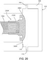
FIG. 20 is a diagrammatic cross-sectional view of another PD cycler that includes a translatable piston head with a peripheral flange that allows the piston head to be mechanically connected to a dome-shaped fastening member of a PD cassette. -
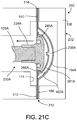
FIGS. 21A-21C are diagrammatic cross-sectional views of a PD cassette in the cassette compartment of the PD cycler ofFIG. 20 , during different phases of a pumping operation. -
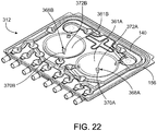
FIG. 22 is a perspective view of a PD cassette that includes dome-shaped fastening members having pegs that allow the dome-shaped fastening members to be mechanically connected to translatable piston heads of a PD cycler. -
FIG. 23 is a diagrammatic side view of a translatable piston head that has a recess containing a clamp with resilient fingers that can engage the peg of one of the dome-shaped fastening members of the PD cassette ofFIG. 22 to mechanically connect the piston head to the dome-shaped fastening member of the PD cassette. Internal features of the piston head are shown in dashed lines. -
FIG. 24 is a front view of the piston head ofFIG. 23 . -
FIG. 25 is a diagrammatic side view of a translatable piston head that has a recess containing a clamp with resilient fingers of a slightly different configuration for engaging the peg of one of the dome-shaped fastening members of the PD cassette ofFIG. 22 to mechanically connect the piston head to the dome-shaped fastening member of the PD cassette. Internal features of the piston head are shown in dashed lines. -
FIG. 26 is a front view of the piston head ofFIG. 25 . - This disclosure relates generally to medical fluid pumping systems and related devices and methods. In some cases, a medical fluid pumping system (e.g., a peritoneal dialysis ("PD") system) includes a medical fluid pumping machine (e.g., a PD cycler) having a piston with a piston head that can be mechanically connected to a medical fluid cassette (e.g., a PD fluid cassette). Typically, the cassette includes a flexible membrane and a fastening member (e.g., a dome-shaped fastening member) attached to the membrane. The membrane and the fastening member overlie a recessed region of a rigid base of the cassette to form a fluid pump chamber, and the piston of the medical fluid pumping machine is designed to be mechanically connected to the fastening member of the cassette. With the piston of the medical fluid pumping machine mechanically connected to the fastening member of the cassette, reciprocation of the piston causes fluid to be alternately drawn into and forced out of the fluid pump chamber by pulling the fastening member and membrane away from the recessed region of the base and then advancing the fastening member and membrane toward the recessed region of the base. As discussed below, in some cases, the piston can be automatically mechanically connected to the fastening member of the cassette by simply moving the piston toward the base of the cassette and into engagement with the fastening member prior to a medical treatment (e.g., PD treatment) and can be automatically disconnected from the fastening member of the cassette by simply moving the piston away from the base of the cassette and out of engagement with the fastening member after completion of the medical treatment.
- Referring to
FIG. 1 , aPD system 100 includes a PD cycler (also referred to as a PD machine) 102 seated on acart 104. Referring also toFIG. 2 , thePD cycler 102 includes ahousing 106, adoor 108, and acassette interface 110 that abuts adisposable PD cassette 112 when thecassette 112 is disposed within acassette compartment 114 formed between thecassette interface 110 and theclosed door 108. Aheater tray 116 is positioned on top of thehousing 106. Theheater tray 116 is sized and shaped to accommodate a bag of dialysis solution (e.g., a 5 liter bag of dialysis solution). ThePD cycler 102 also includes atouch screen 118 andadditional control buttons 120 that can be operated by a user (e.g., a patient) to allow, for example, set-up, initiation, and/or termination of a PD treatment. -
Dialysis solution bags 122 are suspended from fingers on the sides of thecart 104, and aheater bag 124 is positioned on theheater tray 116. Thedialysis solution bags 122 and theheater bag 124 are connected to thecassette 112 via dialysissolution bag lines 126 and aheater bag line 128, respectively. The dialysissolution bag lines 126 can be used to pass dialysis solution fromdialysis solution bags 122 to thecassette 112 during use, and theheater bag line 128 can be used to pass dialysis solution back and forth between thecassette 112 and theheater bag 124 during use. In addition, apatient line 130 and adrain line 132 are connected to thecassette 112. Thepatient line 130 can be connected to a patient's abdomen via a catheter and can be used to pass dialysis solution back and forth between thecassette 112 and the patient during use. Thedrain line 132 can be connected to a drain or drain receptacle and can be used to pass dialysis solution from thecassette 112 to the drain or drain receptacle during use. -
Fig. 3 shows a more detailed view of thecassette interface 110 and thedoor 108 of thePD cycler 102. As shown, thePD cycler 102 includespistons piston shafts 135A, 135B (piston shaft 135A shown inFIG. 4 ) that can be axially moved withinpiston access ports cassette interface 110. Thepiston shafts 135A, 135B are connected to motors that can be operated to move the piston heads 134A, 134B axially inward and outward within thepiston access ports FIGS. 2 and10-13 ) is positioned within thecassette compartment 114 of thePD cycler 102 with thedoor 108 closed, the piston heads 134A, 134B of thePD cycler 102 align withpump chambers cassette 112 such that the piston heads 134A, 134B can be mechanically connected to fastening members of thecassette 112 overlying thepump chambers cassette 112 during treatment can decrease the volume of thepump chambers pump chambers cassette 112 can increase the volume of thepump chambers pump chambers -
FIG. 4 is a diagrammatic cross-sectional view of thePD cycler 102, illustrating thepiston 133A disposed within thepiston access port 136A.FIG. 5 is an exploded, perspective view of thepiston 133A. Because thepistons piston 133B will not be separately described in detail. As shown inFIGS. 4 and5 , thepiston 133A includes apiston shaft 135A to which thepiston head 134A is attached. Thepiston head 134A includes arear member 137A and afront member 139A between which alatch lock 141A, alatch lock spring 143A, and two slidinglatches 145A, 147Aare positioned. The rear andfront members latch lock 141A, thelatch lock spring 143A, and the two slidinglatches front members - The
piston shaft 135A has a reduceddiameter front portion 149A that is sized and shaped to fit within a bore formed in astem 151A of therear member 137A of thepiston head 134A. Typically, the reduceddiameter front portion 149A of thepiston shaft 135A and the inner surface of thestem 151A have threads on their outer and inner surfaces, respectively, such that thepiston head 134A can be secured to thepiston shaft 135A by screwing thestem 151A onto the reduceddiameter front portion 149A of thepiston shaft 135A. This arrangement allows thepiston head 134A to be easily removed from thepiston shaft 135A for cleaning, repair, or replacement. Any of various other securement techniques, such as clipping, welding, adhesive bonding, etc., can alternatively or additionally be used to secure thepiston head 134A to thepiston shaft 135A. - Still referring to
FIGS. 4 and5 , a front end region of thelatch lock spring 143A sits within arecess 153A formed in thefront member 139A of thepiston head 134A, while a rear end of thespring 143A contacts a front-facing surface of thelatch lock 141A. Thelatch lock 141A includeslegs slots latches slots latches legs - The sliding latches 145A, 147A are slidably positioned within
spaces FIG. 4 ) formed between the rear andfront members spaces latches latch lock 141A moves forward relative to thefront member 139A and compresses thespring 143A, the inner surfaces of thelegs latch lock 141A contact the correspondingly angled adjacent surfaces of the slide latches 145A, 147A. Due to the angles of those adjacent surfaces, the frontward movement of thelatch lock 141A causes the slidinglatches latches latches legs latch lock 141A contact and apply radially inward forces to thelatch lock 141A. Due to the geometry of those mating surfaces, the radially inward forces applied to the outer surfaces of thelegs latch lock 141A cause thelatch lock 141A to move forward toward thefront member 139A and compress thespring 143A. Upon releasing the radially inward forces being applied to the slidinglatches latch lock 141A to compress thespring 143A, thespring 143A will expand, causing thelatch lock 141A to move rearward and the slidinglatches - Referring to
FIGS. 5-7 , thelatch lock 141A includes au-shaped member 180A that forms therearwardly extending horns legs u-shaped member 180A at an acute angle relative to the longitudinal axis of thepiston 133A when thepiston 133A is fully assembled.Feet legs feet piston 133A. The front surfaces of thefeet front member 139A of thepiston head 134A when thelatch lock 141A is moved to its fully forward position and thespring 143A is fully compressed. Thelatch lock 141A also includes aprojection 186A (shown inFIG. 7 ) that extends frontward from a central region of theu-shaped member 180A and is attached to or integrally formed with the inner surfaces of thelegs projection 186A supports the rear end of thespring 143A. - The dimensions of the
piston head 134A and its various components will depend on many factors, including the type of cassette with which it is intended to be used. Referring toFIG. 6 , thelatch lock 141A has an overall length L1, which is measured from its frontmost point to its rearmost point along the longitudinal axis of thepiston 133A. The length L1 can be about 1.3 cm (0.5 inch) to about 2.5 cm (1.0 inch) (e.g., 1.9 cm (0.75 inch)). An axial length L2 of the portion of thelatch lock 141A extending forwardly from the inch)). frontmost point of theu-shaped member 180A can be about 0.76 CM (0.3 inch) to about 1 cm (0.4 inch) (e.g., 0.90 cm (0.353 inch)). A length L3 of the straight segment of eachhorn legs piston 133A, can be about 1.3 cm (0.5 inch) to about 2.5 cm (1.0 inch) (e.g., 1.9 cm (0.75 inch)). A distance D1 between the bottom surface of thetop horn 170A and the top surface of thebottom horn 172A can be about 1.27 cm (0.5 inch) to about 3.8 cm (1.5 inch) (e.g., 2.4 cm (0.95 inch)). A distance D2 between the top surface of thetop horn 170A and the bottom surface of thebottom horn 172A can be about 1.9 cm (0.75 inch) to about 3.175 cm (1.25 inch) (e.g., 2.92 cm (1.15 inch)). - Referring to
FIG. 7 , angles α1 and α2, measured between the front surfaces of thefeet leg 157A are about 15 to about 75 degrees (e.g., about 30 to about 60 degrees, about 45 degrees). Theother leg 155A of thelatch lock 141A is a mirror image of theleg 157A. As noted above, the front surfaces of thefeet piston 133A (i.e., the horizontal axis as viewed inFIGS. 4 and7 ). Thus, the outer and inner surfaces of each of thelegs piston 133A. A distance D3 from the outer surface of theleg 155A to the outer surface of theleg 157A at the front ends of thelegs leg 155A, which is substantially the same as the thickness of theleg 157A, is typically slightly smaller (e.g., about 25 to about 51 micrometers smaller) than theslots latches leg 155A can, for example, be about 178 micrometers (0.07 inch) to about 356 micrometers (0.14 inch) (e.g., 287 micrometers (0.113 inch)). - Referring now to
FIGS. 5 ,8, and 9 , the slidinglatch 145A includes a lead-in surface or frontangled surface 188A that first contacts the dome-shapedmember 161A as thepiston head 134A is being mechanically connected to the dome-shapedmember 161A, as described below. The slidinglatch 145A also includes a lead-out surface or rearangled surface 190A that contacts the dome-shapedmember 161A as thepiston head 134A is being disconnected from the dome-shapedmember 161A. The outer edge of the rearangled surface 190A and the outer edge of a central portion of the slidinglatch 145A from which the rearangled surface 190A extends are arched. These outer edges can have radii of curvature that approximate the radius of curvature of the inner surface of the dome-shapedmember 161A. The slidinglatch 145A further includes a cut-outportion 192A that is located adjacent theslot 169A and is sized and shaped to receive a portion of theprojection 186A extending from thelatch lock 141A when thepiston head 134A is fully assembled. - Referring to
FIG. 8 , in some implementations, the slidinglatch 145A has an overall length L3 of about 2.29 cm (0.9 inch) to about 2.8 cm (1.1 inch) (e.g., 2.48 cm (0.975 inch) or 2.5 cm (0.985 inch)). and/or an overall width W1 of about 1.65 cm (0.65 inch) to about 1.78 cm (0.7 inch (e.g., 1.7 cm (0.67 inch)). Theslot 169A of the slidinglatch 145A is typically slightly larger than theleg 155A of thelatch lock 141A, which is disposed in theslot 169A when thepiston head 134A is fully assembled. Theslot 169A can, for example, have a length L4 of about 1.78 cm (0.7 inch) to about 2.3 cm (0.9 inch) (e.g., 2.0 cm (0.8 inch)). As shown inFIG. 9 , theslot 169A can have a width W2 of about 250 micrometers 0.1 inch) to about 381 micrometers (0.15 inch) (e.g. 318 micrometers (0.125 inch) or 343 micrometers (0.135 inch)). - Still referring to
FIG. 9 , the rearangled surface 190A can have a width W3 of 381 micrometers (0.15 inch) to 508 micrometers (e.g., 434 micrometers (0.171 inch)). about. The frontangled surface 188A is arranged at an angle α3 of about 15 degrees to about 75 degrees (e.g., about 30 degrees to about 60 degrees, 45 degrees) relative to a plane that is perpendicular to the longitudinal axis of thepiston 133A. Thus, the frontangled surface 188A is angled at about 15 degrees to about 75 degrees (e.g., about 30 degrees to about 60 degrees, 45 degrees) relative to the longitudinal axis of thepiston 133A. The rearangled surface 190A is arranged at an angle α4 of about 15 degrees to about 45 degrees (e.g., 20 degrees, 25 degrees, or 30 degrees) relative to a plane that is perpendicular to the longitudinal axis of thepiston 133A. Thus, the rearangled surface 190A is angled at about 45 degrees to about 75 degrees (e.g., 60 degrees, 65 degrees, or 70 degrees) relative to the longitudinal axis of thepiston 133A. The inner and outer surfaces of the slidinglatch 145A that define theslot 169A are arranged at angles α5, α6, measured relative to the longitudinal axis of thepiston 133A, that are typically approximately the same as the angles at which the inner and outer surfaces of theleg 155A of thelatch lock 141A are arranged. The angles α5, α6 can, for example, be about 15 degrees to about 75 degrees (e.g., about 30 degrees to about 60 degrees, 45 degrees). - The
latch lock spring 143A typically has a spring rate of about 38 pounds per inch to about 67 pounds per inch and typically provides sufficient resistance to prevent radial inward forces of about 6.7 N (1.5 lbf) to about 42 N (9.5 lbf) applied to the slidinglatches latches - The
piston head 134A andpiston shaft 135A can be formed of various different polymers, metals, and/or alloys. Therear member 137A, thefront member 139A, and thelatch lock 141A are typically formed of materials that are relatively rigid, resistance to wear, and have a relatively low coefficient of friction. Examples of suitable materials for these components include polyoxymethylene (e.g., Delrin), aluminum, steel, bronze, brass, and PTFE. However, other metals and plastics having relatively low coefficients of friction can alternatively or additionally be used. The sliding latches 145A, 147A are similarly typically formed of materials that are relatively rigid, resistance to wear, and have a relatively low coefficient of friction. In some implementations, the slidinglatches latches - The various components of the
piston head 134A and thepiston shaft 135A can be formed using any of various different techniques, including machining techniques molding techniques, and/or casting techniques. - Referring back to
FIG. 3 , thePD cycler 102 also includes multipleinflatable members 142 positioned withininflatable member ports 144 in thecassette interface 110. Theinflatable members 142 align withdepressible dome regions 146 of the cassette 112 (shown inFIGS. 10-13 ) when thecassette 112 is positioned within thecassette compartment 114 of thePD cycler 102. While only one of theinflatable members 142 is labeled inFIG. 3 , it should be understood that thePD cycler 102 includes an inflatable member associated with each of thedepressible dome regions 146 of thecassette 112. Theinflatable members 142 act as valves to direct dialysis solution through thecassette 112 in a desired manner during use. In particular, theinflatable members 142 bulge outward beyond the surface of thecassette interface 110 and into contact with thedepressible dome regions 146 of thecassette 112 when inflated, and retract into theinflatable member ports 144 and out of contact with thecassette 112 when deflated. By inflating certaininflatable members 142 to depress their associateddome regions 146 on thecassette 112, certain fluid flow paths within thecassette 112 can be occluded. Thus, PD solution can be pumped through thecassette 112 by actuating the piston heads 134A, 134B, and can be guided along desired flow paths within thecassette 112 by selectively inflating and deflating theinflatable members 142. - Still referring to
FIG. 3 , locatingpins 148 extend from thecassette interface 110 of thePD cycler 102. When thedoor 108 is in the open position, thecassette 112 can be loaded onto thecassette interface 110 by positioning the top portion of thecassette 112 under the locating pins 148 and pushing the bottom portion of thecassette 112 toward thecassette interface 110. Thecassette 112 is dimensioned to remain securely positioned between the locatingpins 148 and a spring loadedlatch 150 extending from thecassette interface 110 to allow thedoor 108 to be closed over thecassette 112. The locating pins 148 help to ensure that proper alignment of thecassette 112 within thecassette compartment 114 is maintained during use. - The
door 108 of thePD cycler 102, as shown inFIG. 3 , definescylindrical recesses pistons door 108 is in the closed position. When the cassette 112 (shown inFIGS. 10-13 ) is positioned within thecassette compartment 114,hollow projections cassette 112, inner surfaces of which partially define thepump chambers recesses door 108 further includes a pad that is inflated during use to compress thecassette 112 between thedoor 108 and thecassette interface 110. With the pad inflated, the portions of thedoor 108 forming therecesses projections cassette 112 and the planar surface of thedoor 108 supports the other regions of thecassette 112. Thedoor 108 can counteract the forces applied by theinflatable members 142 and thus allows theinflatable members 142 to actuate thedepressible dome regions 146 on thecassette 112. The engagement between thedoor 108 and thehollow projections cassette 112 can also help to hold thecassette 112 in a desired fixed position within thecassette compartment 114 to further ensure that thepistons fluid pump chambers cassette 112. -
FIG. 10 is an exploded, perspective view of thecassette 112,FIG. 11 is a perspective, cross-sectional view of the fully assembledcassette 112, andFIGS. 12 and13 are perspective views of the assembledcassette 112, from the membrane side and from the rigid base side, respectively. Referring toFIGS. 10-12 , thecassette 112 includes aflexible membrane 140 attached to a periphery of the tray-likerigid base 156. Rigid dome-shapedfastening members regions base 156. The dome-shapedmembers PD cycler 102. In certain implementations, the dome-shapedmembers flanges regions annular flanges members membrane 140 surrounding substantiallycircular apertures membrane 140. Theapertures members members - The
annular flanges members FIG. 11 , formannular projections annular projections members members inward projections latches members membrane 140 is attached to the dome-shapedmembers members regions pistons flexible membrane 140 to similarly be moved into and out of the recessedregions base 156. This movement allows fluid to be forced out of and drawn into thefluid pump chambers regions base 156 and the portions of the dome-shapedmembers membrane 140 that overlie those recessedregions - Referring to
FIGS. 10 and12 , raisedridges 167 extend from the substantially planar surface of the base 156 towards and into contact with the inner surface of theflexible membrane 140 when thecassette 112 is compressed between thedoor 108 and thecassette interface 110 of thePD cycler 102 to form a series offluid passageways 158 and to form the multiple,depressible dome regions 146, which are widened portions (e.g., substantially circular widened portions) of thefluid pathways 158, as shown inFIG. 12 . Thefluid passageways 158 fluidly connect thefluid line connectors 160 of thecassette 112, which act as inlet/outlet ports of thecassette 112, to thefluid pump chambers inflatable valve members 142 of thePD cycler 102 act on thecassette 112 during use. During use, the dialysis solution flows to and from thepump chambers fluid pathways 158 anddome regions 146. At eachdepressible dome region 146, themembrane 140 can be deflected to contact the planar surface of the base 156 from which the raisedridges 167 extend. Such contact can substantially impede (e.g., prevent) the flow of dialysis solution along the region of thepathway 158 associated with thatdome region 146. Thus, the flow of dialysis solution through thecassette 112 can be controlled through the selective depression of thedepressible dome regions 146 by selectively inflating theinflatable members 142 of thePD cycler 102. - Still referring to
FIGS. 10 and12 , thefluid line connectors 160 are positioned along the bottom edge of thecassette 112. As noted above, thefluid pathways 158 in thecassette 112 lead from thepumping chambers various connectors 160. Theconnectors 160 are positioned asymmetrically along the width of thecassette 112. The asymmetrical positioning of theconnectors 160 helps to ensure that thecassette 112 will be properly positioned in thecassette compartment 114 with themembrane 140 of thecassette 112 facing thecassette interface 110. Theconnectors 160 are configured to receive fittings on the ends of the dialysissolution bag lines 126, theheater bag line 128, thepatient line 130, and thedrain line 132. One end of the fitting can be inserted into and bonded to its respective line and the other end can be inserted into and bonded to its associatedconnector 160. By permitting the dialysissolution bag lines 126, theheater bag line 128, thepatient line 130, and thedrain line 132 to be connected to the cassette, as shown inFIGS. 1 and2 , theconnectors 160 allow dialysis solution to flow into and out of thecassette 112 during use. - The rigidity of the
base 156 helps to hold thecassette 112 in place within thecassette compartment 114 of thePD cycler 102 and to prevent the base 156 from flexing and deforming in response to forces applied to theprojections members inflatable members 142. - The
base 156 and the dome-shapedmembers cassette 112 can be formed of any of various relatively rigid materials. In some implementations, these components of thecassette 112 are formed of one or more polymers, such as polypropylene, polyvinyl chloride, polycarbonate, polysulfone, and other medical grade plastic materials. In certain implementations, these components can be formed of one or more metals or alloys, such as stainless steel. These components of can alternatively be formed of various different combinations of the above-noted polymers and metals. These components of thecassette 112 can be formed using any of various different techniques, including machining, molding, and casting techniques. - As noted above, the
membrane 140 is attached to the periphery of thebase 156 and to theannular flanges members membrane 140 overlying the remaining portions of the base 156 are typically not attached to thebase 156. Rather, these portions of themembrane 140 sit loosely atop the raisedridges 165A, 165B, and 167 extending from the planar surface of thebase 156. Any of various attachment techniques, such as adhesive bonding and thermal bonding, can be used to attach themembrane 140 to the periphery of thebase 156 and to the dome-shaped members. The thickness and material(s) of themembrane 140 are selected so that themembrane 140 has sufficient flexibility to flex toward the base 156 in response to the force applied to themembrane 140 by theinflatable members 142. In certain implementations, themembrane 140 is about 0.100 micron to about 0.150 micron in thickness. However, various other thicknesses may be sufficient depending on the type of material used to form themembrane 140. - Any of various different materials that permit the
membrane 140 to deflect in response to movement of theinflatable members 142 without tearing can be used to form themembrane 140. In some implementations, themembrane 140 includes a three-layer laminate. In certain implementations, for example, inner and outer layers of the laminate are formed of a compound that is made up of 60 percent Septon® 8004 thermoplastic rubber (i.e., hydrogenated styrenic block copolymer) and 40 percent ethylene, and a middle layer is formed of a compound that is made up of 25 percent Tuftec® H1062(SEBS: hydrogenated styrenic thermoplastic elastomer), 40 percent Engage® 8003 polyolefin elastomer (ethylene octene copolymer), and 35 percent Septon® 8004 thermoplastic rubber (i.e., hydrogenated styrenic block copolymer). The membrane can alternatively include more or fewer layers and/or can be formed of different materials. - As shown in
FIG. 14 , before treatment, thedoor 108 of thePD cycler 102 is opened to expose thecassette interface 110, and thecassette 112 is positioned with its dome-shapedmembers pistons PD cycler 102 and with itsmembrane 140 adjacent to thecassette interface 110. In order to ensure that the dome-shapedmembers pistons cassette 112 is positioned between the locatingpins 148 and the spring loadedlatch 150 extending from thecassette interface 110. The asymmetrically positionedconnectors 160 of the cassette act as a keying feature that reduces the likelihood that thecassette 112 will be installed with themembrane 140 and dome-shapedmembers pins 148 can be dimensioned to be less than the maximum protrusion of theprojections cassette 112 cannot contact the locating pins 148 if themembrane 140 is facing outward toward thedoor 108. Thepistons piston access ports cassette 112 to avoid interference betweenpistons members cassette 112 can be positioned within thecassette compartment 114. -
FIGS. 15A-15F are diagrammatic cross-sectional views of thePD system 100 with thePD cassette 112 disposed in thecassette compartment 114 of thePD cycler 102, during different phases of a pumping operation used to draw dialysis solution into thepump chamber 138A and to force dialysis solution out of thepump chamber 138A. The technique for pumping solution to and from theother pump chamber 138B is identical and thus is not separately described in detail. -
FIG. 15A shows thecassette 112 positioned within thecassette compartment 114 shortly after installation. As shown, thecassette 112 is positioned adjacent to thecassette interface 110 and thedoor 108 is closed over thecassette 112 such that thecassette 112 is contained within thecassette compartment 114 between thedoor 108 and thecassette interface 110. Thepiston head 134A is retracted into thepiston access port 136A such that thepiston head 134A does not interfere with thecassette 112 during its installation. With thecassette 112 positioned in thecassette compartment 114, the inflatable pad within thedoor 108 is inflated to compress thecassette 112 between thedoor 108 and thecassette interface 110. This compression of thecassette 112 holds theprojection 154A of thecassette 112 in therecess 152A of thedoor 108 and presses themembrane 140 tightly against the raisedridges 167 extending from the planar surface of therigid base 156 to form the enclosedfluid pathways 158 and dome regions 146 (shown inFIG. 12 ). - As shown in
FIG. 15B , once thecassette 112 has been installed within thecassette compartment 114 of thePD cycler 102, thepiston 133A is advanced to initiate the process of mechanically connecting thepiston head 134A of thePD cycler 102 to the dome-shapedmember 161A of thecassette 112. Thepiston 133A can be advanced at a rate of about 2.0 cm (0.8 inch)/minute to about 28 cm (11 inches)/minutes and with an axial force of about 22 N (5 lbf) to about 222 N (50 lbf). As thepiston 133A is advanced, the frontangled surface 188A of the slidinglatch 145A and a frontangled surface 191A of the slidinglatch 147A contact a rear surface of theannular projection 168A, which extends radially inward from the dome-shapedmember 161A. The rear surface of theannular projection 168A is approximately perpendicular to the longitudinal axis of thepiston 133A. - As the
piston 133A continues to advance, the dome-shapedmember 161A contacts the inner surface of the portion of therigid base 156 that forms the recessedregion 162A, as shown inFIG. 15B . Therigid base 156 prevents further forward movement of the dome-shapedmember 161A. Themembrane 140, which is attached to theperipheral flange 164A of the dome-shapedmember 161A, also stretches and moves into the recessedregion 162A due to the advancingpiston 133A. Due to the angled geometries of the frontangled surfaces latches rigid base 156 to the forward motion of the dome-shapedmember 161A, the slidinglatches piston 133A) as thepiston head 134A continues to be advanced relative to the dome-shapedmember 161A. More specifically, the forward motion of the slidinglatches angled surfaces latches annular projection 168A of the dome-shapedmember 161A. The radial inward movement of each of the slidinglatches latch lock 141A due to the mated geometries of the outer surfaces of thelegs latch lock 141A and the surfaces of the slidinglatches legs latch lock 141A is resisted by thespring 143A. -
FIG. 15C shows thepiston head 134A at a point during the connection process at which the slidinglatches latches annular projection 168A that extends radially inward from the dome-shapedmember 161A. In this position, outer peripheral surfaces of the slidinglatches piston 133A, contact and slide along an inner surface of theprojection 168A of the dome-shapedmember 161A, which is also substantially parallel to the longitudinal axis of thepiston 133A. Thespring 143A is further compressed due to the radially inwardly deflected positions of the slidinglatches - Referring to
FIG. 15D , as the slidinglatches 145A, 147Apass beyond theprojection 168A, thespring 143A is allowed to expand. The expansion of thespring 143A causes thelatch lock 141A to move rearward. As a result, the outer surfaces of thelegs latch lock 141A contact the correspondingly angled adjacent surfaces of the slidinglatches latches projection 168A of the dome-shapedmember 161A. The rearangled surfaces latches projection 168A of the dome-shapedmember 161A, which is slightly angled toward the rear of the dome-shapedmember 161A (e.g., angled at about 88 degrees relative to the longitudinal axis of thepiston head 133A), as the slidinglatches projection 168A as the slidinglatches - The rear
angled surfaces latches piston head 134A to be firmly locked within dome-shaped members of slightly different sizes. For example, due to imperfect manufacturing techniques, the thickness of theannular projection 168A along the longitudinal axis of thepiston 133A may differ slightly (e.g., by about 76 to about 127 micrometers (0.003 to about 0.005 inch) amongst different molded dome-shaped members. The rear angled surfaces of the slidinglatches -
FIG. 15E illustrates the complete mechanical connection between thepiston head 134A and the dome-shapedmember 161A in which the slidinglatches member 161A. In this configuration, theprojection 168A of the dome-shapedmember 161A is effectively pinched between therear member 137A of thepiston head 134A and the slidinglatches piston head 134A and the dome-shapedmember 161A. As a result of the secure engagement of thepiston head 134A to the dome-shapedmember 161A, the amount of slippage of thepiston head 134A relative to the dome-shapedmember 161A can be reduced (e.g., minimized) and thus precise pumping can be achieved. - As discussed above, as the
piston 133A is being mechanically connected to the dome-shapedmember 161A, the dome-shapedmember 161A is advanced into the recessedregion 162A of therigid base 156 until the dome-shapedmember 161A contacts the inner surface of the recessedregion 162A of thebase 156 of thecassette 112. This movement decreases the volume of thepump chamber 138A formed between the dome-shapedmember 161A, themembrane 140, and the recessed region of thebase 156, and thus causes any fluid (e.g., priming fluid) within thepump chamber 138A to be forced out of thepump chamber 138A from thefluid pathways 158 of the cassette via theinlet port 185A (shown inFIG. 10 ). - Referring to
FIG. 15F , after thepiston 133A has been mechanically connected to the dome-shapedmember 161A, thepiston 133A is retracted to draw dialysis solution into thepump chamber 138A. Because thepiston head 134A is mechanically connected to the dome-shapedmember 161A and the dome-shapedmember 161A is attached to themembrane 140 of thecassette 112, the retraction of thepiston 133A causes the dome-shapedmember 161A and the portion of themembrane 140 attached to the dome-shapedmember 161A to move rearwardly. As a result, the volume of thepump chamber 138A is increased and fluid is drawn into thepump chamber 138A. - Because the volumes of the
fluid pump chamber 138A and thepiston head 134A are known, the linear distance travelled by thepiston 133A can be used to determine the volume of dialysis solution drawn into thefluid pump chamber 138A. The linear distance travelled by thepiston 133A can be determined based on the number of revolutions or steps of the motor (e.g., stepper motor) used to drive thepiston 133A. Thus, the volume of solution drawn into thefluid pump chamber 138A can be determined based on the number of revolutions or steps of the motor. The tight fit between thepiston head 134A and the dome-shapedmember 161A ensure the accuracy of the volume of solution determined in this manner. - After drawing the dialysis solution into the
pump chamber 138A, the dialysis solution is forced out of thepump chamber 138A by again advancing thepiston 133A and decreasing the volume of thepump chamber 138A. Thepiston 133A is typically advanced until the dome-shapedmember 161A contacts or nearly contacts the inner surface of the recessed region of the base 156 so that substantially all of the dialysis solution is forced out of thefluid pump chamber 138A via theoutlet port 187A (shown inFIG. 10 ). - This process of drawing dialysis solution into the
fluid pump chamber 138A and then forcing the dialysis solution out of thefluid pump chamber 138A is repeated until a desired volume of dialysis solution has been pumped to or from a location (e.g., to or from the patient). - As noted above, while forcing dialysis solution into and out of the
pump chambers inflatable members 142 of thePD cycler 102 can be selectively inflated to direct the pumped dialysis solution along desired pathways in thecassette 112. - Referring back to
FIGS. 1 and2 , during PD treatment, thepatient line 130 is connected to a patient's abdomen via a catheter, and thedrain line 132 is connected to a drain or drain receptacle. The PD treatment typically begins by emptying the patient of spent dialysis solution that remains in the patient's abdomen from the previous treatment. To do this, the pump of thePD cycler 102 is activated to cause thepistons inflatable members 142 are inflated to cause the spent dialysis solution to be drawn into thefluid pump chambers cassette 112 from the patient. The spent dialysis solution is then pumped from thefluid pump chambers drain line 132. - After draining the spent dialysis solution from the patient, heated dialysis solution is transferred from the
heater bag 124 to the patient. To do this, the motor or motors of thePD cycler 102 is/are activated to cause thepistons inflatable members 142 of thePD cycler 102 are inflated to cause the warmed dialysis solution to be drawn into thefluid pump chambers cassette 112 from theheater bag 124 via theheater bag line 128. The warmed dialysis solution is then pumped from thefluid pump chambers patient line 130. - Once the dialysis solution has been pumped from the
heater bag 124 to the patient, the dialysis solution is allowed to dwell within the patient for a period of time. During this dwell period, toxins cross the peritoneum of the patient into the dialysis solution from the patient's blood. As the dialysis solution dwells within the patient, thePD cycler 102 prepares fresh dialysate for delivery to the patient in a subsequent cycle. In particular, thePD cycler 102 pumps fresh dialysis solution from one of the four fulldialysis solution bags 122 into theheater bag 124 for heating. To do this, the pump of thePD cycler 102 is activated to cause thepistons inflatable members 142 of thePD cycler 102 are inflated to cause the dialysis solution to be drawn into thefluid pump chambers cassette 112 from the selecteddialysis solution bag 122 via its associatedline 126. The dialysis solution is then pumped from thefluid pump chambers heater bag 124 via theheater bag line 128. - After the dialysis solution has dwelled within the patient for the desired period of time, the spent dialysis solution is pumped from the patient to the drain. The heated dialysis solution is then pumped from the
heater bag 124 to the patient where it dwells for a desired period of time. These steps are repeated with the dialysis solution from two of the three remainingdialysis solution bags 122. The dialysis solution from the lastdialysis solution bag 122 is typically delivered to the patient and left in the patient until the subsequent PD treatment. - While the dialysis solution has been described as being pumped into the
heater bag 124 from a singledialysis solution bag 122, dialysis solution can alternatively be pumped into theheater bag 124 from multipledialysis solution bags 122. Such a technique may be advantageous, for example, where the dialysis solutions in thebags 122 have different concentrations (e.g., different dextrose concentrations) and a desired concentration for treatment is intermediate to the concentrations of the dialysis solution in two or more of thebags 122. - After completion of the PD treatment, the
pistons members FIGS. 16-19 . Because the piston heads 134A, 134B are substantially identical, the disconnection process will only be described in detail with respect to thepiston head 134A. As shown inFIGS. 16 and 17 , which are different cross-sectional views of thepiston head 134A connected to the dome-shapedmember 161A, the horns orprojections latch lock 141A extend rearwardly through apertures formed in therear member 137A of thepiston head 134A. Thehorns horns rear member 137A or are flush with the rear surface of therear member 137A when thelatch lock 141A is advanced to its fully forward position and thespring 143A is compressed. - The
horns latches piston head 134A to be disconnected from the dome-shapedmember 161A of thecassette 112.FIG. 18 is a double cross-sectional view of thepiston head 134A mechanically connected to the dome-shapedmember 161A. As shown inFIG. 18 , when thepiston head 134A and the dome-shapedmember 161A are mechanically connected, thehorns rear member 137A and rearwardly beyond the rear surface of that member. In this position, thespring 143A of thepiston head 134A is expanded and holds the latch lock 141 in its rearmost position, causing thehorns rear member 137A. -
FIG. 19 is a double cross-sectional view of thepiston head 134A in a configuration to be mechanically disconnected from the dome-shapedmember 161A. In this configuration, thehorns rear member 137A. As a result, thelatch lock 141A is moved to its forward most position and thespring 143A is compressed. - As the
piston 133A is reciprocated during treatment, thehorns FIGS. 15A-15F ) of thePD cycler 102. As a result, thehorns piston 133A is retracted a sufficient distance so that thehorns surface 174 of thePD cycler 102. Continued retraction of thepiston 133A pushes thehorns rear member 137A and causes thelatch lock 141A to move forward relative to thefront member 139A, thereby compressing thespring 143A, as shown inFIG. 19 . As a result, the inner angled surfaces of thelegs latch lock 141A press against the adjacent, similarly angled surfaces of the slidinglatches latches latches projection 168A (shown inFIGS. 15A-15F ) of the dome-shapedmember 161A. Further retraction of thepiston 133A causes thepiston head 134A to be backed out of the dome-shapedmember 161A of thecassette 112. Alternatively or additionally, the resilience of the stretchedmembrane 140 can cause themembrane 140 and the dome-shapedmember 161A to snap forward and out of contact with thepiston head 134A as the slidinglatches projection 168A of the dome-shapedmember 161A. - After the
pistons members cassette 112 in the manner described above, thedoor 108 of the PD cycler is opened and thecassette 112 is removed from thecassette compartment 114 and discarded. - Because the
PD system 100 does not require a vacuum system to draw liquid into thefluid pump chambers door 108 and thecassette interface 110 is typically not required. Thus, as compared to systems including a vacuum system adapted to retract portions of the cassette membrane overlying pump chambers, the door sealing mechanism of thePD cycler 102 can be simpler and more cost effective. In addition, the reduced use of vacuum pressure relative to certain conventional cyclers can result in quieter operation. - While certain implementations have been described, other implementations are possible.
- While the piston heads 134A, 134B have been described as including springloaded latch mechanisms with sliding
latches 145A, 145B that can be move radially inward and outward to allow those piston heads 134A, 134B to be mechanically connected to the dome-shapedmembers cassette 112, piston heads of simpler construction that include no such sliding latches can alternatively be used in some cases.FIG. 20 illustrates aPD cycler 202 including apiston 233A that has one such type ofpiston head 234A connected to itspiston shaft 135A. ThePD cycler 202 is essentially the same as thePD cycler 102 described above except the pistons include different types of piston heads than the pistons in thePD cycler 102 described above. Like thePD cycler 102, thePD cycler 202 also includes a second piston that has a substantially identical structure and function to thepiston 233A illustrated inFIG. 20 and thus will not be separately described in detail. - Still referring to
FIG. 20 , thepiston head 234A is a unitary structure that includes aperipheral flange 245A that can be engaged with an annular projection of a dome-shaped member of a cassette in order to mechanically connect thepiston head 234A to the cassette and enable a fluid pumping process of the type described above to be carried out. The rear surface of theflange 245A can be arranged at an angle of about 45 degrees to about 75 degrees (e.g., about 60 degrees) relative to the longitudinal axis of the piston. Thepiston head 234A can be formed using any of the materials and techniques described above with respect to thepiston head 134A. Similarly, thepiston head 234A can be secured to thepiston shaft 135A using any of the attachment techniques discussed above for attaching thepiston head 134A to thepiston shaft 135A. -
FIGS. 21A-21C are diagrammatic cross-sectional views of aPD system 200 that includes aPD cassette 212 disposed in thecassette compartment 114 of thePD cycler 202, during different phases of a pumping operation used to draw dialysis solution into a pump chamber 23 8A of thecassette 212 and to force dialysis solution out of thepump chamber 238A of thecassette 212. Thecassette 212 is very similar to thecassette 112 described above. However, thecassette 212 includes a rigid dome-shapedmember 261A that is shaped slightly differently than the dome-shapedmember 161A described above. The technique for pumping solution to and from the other pump chamber of thecassette 212 is identical and thus is not separately described in detail. - As shown in
FIG. 21A , once thecassette 212 has been installed within thecassette compartment 114 of thePD cycler 202, thepiston 233A is advanced to initiate the process of connecting thepiston head 234A of thePD cycler 202 to the dome-shapedmember 261A of thecassette 212. As thepiston 233A is advanced, theflange 245A of thepiston head 234A contacts the lead-in chamfer or rear surface of anannular projection 268A that extends radially inward from the dome-shapedmember 261A and pushes the dome-shapedmember 261A into contact with therigid base 156 of thecassette 212. The front surface of theflange 245A of thepiston head 234A and the rear surface of theannular projection 268A of the dome-shapedmember 261A are generally arranged to approximately mate with one another. The leading front surface of theflange 245A of thepiston head 234A is typically angled rearwardly at about 45 to about 75 degrees (e.g., about 60 degrees) relative to the longitudinal axis of thepiston 233A. The rear surface of the annular projection is typically angled frontwardly at about 45 to about 75 degrees (e.g., about 60 degrees) relative to the longitudinal axis of thepiston 233A. Due to the geometry and rigidity of theflange 245A of thepiston head 234A, advancing thepiston head 234A into the dome-shapedmember 261A of thecassette 212 causes the peripheral side wall of thecassette 212 from which theprojection 268A extends to deflect radially outwardly, allowing theflange 245A to slide past theprojection 268A. The dome-shapedmember 261A of thecassette 212 is resilient so that theprojection 268A snaps back into place behind the flange 245 after the flange 245 slides past theprojection 268A. The engagement between theflange 245A and theprojection 268A holds thepiston head 234A secured to the dome-shapedmember 261A of thecassette 212 to permit pumping action to be applied to thecassette 212 by thepiston 233A. - As the
piston head 234A is mechanically connected to the dome-shapedmember 261A in the manner described above, the volume of thepump chamber 238A formed between the dome-shapedmember 261A, themembrane 140 decreases due to the forward movement of the dome-shapedmember 261A into the recessedregion 162A of thebase 156, and thus causes any fluid (e.g., priming fluid) within thepump chamber 238A to be forced out of thepump chamber 238A. - Referring to
FIG. 21C , thepiston 233A is then retracted to draw dialysis solution into thepump chamber 238A. Because thepiston head 234A is mechanically connected to the dome-shapedmember 261A and the dome-shapedmember 261A is attached to themembrane 140 of thecassette 212, the retraction of thepiston 233A causes the dome-shapedmember 261A and the portion of themembrane 140 attached to the dome-shapedmember 261A to move rearwardly. As a result, the volume of the pump chamber 23 8A is increased and fluid is drawn into the pump chamber 23 8A. - After drawing the dialysis solution into the
pump chamber 238A, the dialysis solution is forced out of thepump chamber 238A by again advancing thepiston 233A and decreasing the volume of thepump chamber 238A. As discussed above, this process of drawing dialysis solution into thefluid pump chamber 238A and then forcing the dialysis solution out of thefluid pump chamber 238A can be repeated until a desired volume of dialysis solution has been pumped to or from a location (e.g., to or from the patient) during a PD treatment. - To mechanically disconnect the
piston head 234A from the dome-shapedmember 261A after treatment, thepiston 233A is retracted farther than it is retracted during treatment. This retraction causes the rear surface of the peripheral flange of the dome-shapedmember 261A to contact thesurface 174 of thePD cycler 202 such that the dome-shapedmember 261A is prevented from moving any further in the rearward direction. Thepiston 233A continues to retract such that thepiston head 234A slides rearwardly relative to the dome-shapedmember 261A. The rear surface of theflange 245A of thepiston head 234A is typically angled frontwardly at about 60 to about 80 degrees (e.g., about 70 degrees) relative to the longitudinal axis of thepiston 233A. The front surface of theannular projection 268A is typically angled rearwardly at about 60 to about 80 degrees (e.g., about 70 degrees) relative to the longitudinal axis of thepiston 233A. As a result of the orientation of these surfaces and the inability of the dome-shapedmember 261A to move further rearwardly, the rearward motion of thepiston head 234A causes the portions of the dome-shapedmember 261A from which theannular projection 268A extends to deflect radially outwardly. This allows theflange 245A of thepiston head 234A to slide past theannular projection 268A resulting in thepiston head 234A being mechanically disconnected from the dome-shapedmember 261A. - While the
piston head 234A andcassette 212 have been described as being constructed so that the peripheral side walls of thecassette 212 deflect outwardly as thepiston head 234A is advanced into and retracted out of the dome-shapedmember 261A, they can alternatively or additionally be designed so that wall of thepiston head 234A from which theflange 245A extends deflects radially inwardly to allow theflange 245A of thepiston head 234A to slide past theprojection 268A of thecassette 212. - While the
cassette 212 and thePD cycler 202 described above are designed so that the rear surface of the peripheral flange of the dome-shaped member 261 contacts thesurface 174 of thePD cycler 202 during the disconnection process, in certain implementations, themembrane 140 itself may provide sufficient resistance to rearward movement of the dome-shapedmember 261A to allow thepiston head 234A to be disconnected from the dome-shapedmember 261A. - Other structures for enabling a mechanical connection between piston heads and a cassette can also be used. As shown in
FIG. 22 , for example, acassette 312, which is structurally very similar to thecassette 112 described above, includespegs members regions base 156 of thecassette 112 and are attached to themembrane 140 of thecassette 312 in the same way as the dome-shapedmembers cassette 112 discussed above. Each of thepegs stem member cassette 312 and anenlarged head stem members pegs members -
FIGS. 23 and 24 illustrate apiston head 334A that can be secured to thepiston shaft 135A of one of the PD cyclers described above and can engage thepeg 345A of thecassette 312 to allow a pumping action to be produced in a pump chamber formed between a recessed region of thebase 156 of thecassette 312 and the dome-shapedmember 361A andmembrane 140 when the piston is reciprocated. It will be appreciated that an identical piston head could be secured to the other piston shaft 135B of the PD cycler to enable a similar pumping action to be produced within the pump chamber adjacent the other dome-shapedmember 361B. As shown inFIGS. 23 and 24 , thepiston head 334A includes abore 336A in which aclamp mechanism 338A including tworesilient spring fingers spring fingers annular projection 390A of thepiston head 334A. Any of various attachment techniques, such as adhesive bonding, thermal welding, and/or mechanical fastening techniques, can be used to attach thespring fingers annular projection 390A. - Still referring to
FIGS. 23 and 24 , thespring finger 345A includes front andrear projections finger 345A, and thespring finger 347A includes front andrear projections finger 347A. Thefront projections piston head 334A to thepeg 368A thepiston head 334A is advanced into the dome-shapedmember 361A such that front surfaces of theprojections spring fingers enlarged head 372A of thepeg 368A. Due to the angled orientation of the font surfaces of theprojections piston head 334A causes thespring fingers projections enlarged head 372A of thepeg 368A. Thespring fingers enlarged head 372A of thepeg 368A to slide forward past theprojections enlarged head 372A to become fixed within a space formed between the front and rear projections of thespring fingers rear projections piston head 334A will not cause thespring fingers enlarged head 372A of thepeg 368A is disposed in the space between the front and rear projections of thespring fingers piston head 334A and thepeg 368A engaged in this manner, reciprocation of thepiston head 334A causes movement of the dome-shapedmember 361A and the surrounding portion of themembrane 140 and thus causes fluid to be pumped into and out of the pump chamber of thecassette 312 in the same manner as described above. - Like the front surfaces of the
front projections spring fingers rear projections internal shaft 357A sits within an axial bore formed in thepiston head 334A positioned behind thebore 336A in which theclamp mechanism 338A is contained. Theinternal shaft 357A is fixed to the housing of the PD cycler such that thepiston head 334A moves relative to theshaft 357A as thepiston head 334A reciprocates. To disconnect thepiston head 334A from thepeg 368A after treatment, thepiston head 334A is retracted into the PD cycler a sufficient distance so that theshaft 357A contacts the rear surfaces of therear projections spring fingers rear projections spring fingers piston head 334A causes thefront projections peg 368A. -
FIGS. 25 and 26 illustrate a slightlydifferent piston head 434A that can be secured to thepiston shaft 135A of one of the PD cyclers described above and can engage thepeg 345A of thecassette 312 to allow a pumping action to be produced in a pump chamber formed between a recessed region of thebase 156 of thecassette 312 and the dome-shapedmember 361A andmembrane 140 when the piston is reciprocated. As shown inFIGS. 25 and 26 , thepiston head 434A includes abore 436A in which a clamp mechanism 43 8A including tworesilient spring fingers spring fingers piston head 434A. Any of various attachment techniques, such as adhesive bonding, thermal welding, and/or mechanical fastening techniques, can be used to attach thespring fingers annular projection 490A. - Still referring to
FIGS. 25 and 26 , thespring fingers projections fingers projections piston head 434A is mechanically connected to thecassette 312 in much the same way as thepiston head 334A described above. In particular, thepiston head 434A is advanced into the dome-shapedmember 361A such that front surfaces of theprojections spring fingers enlarged head 372A of thepeg 368A and, due to the angled orientation of the font surfaces of theprojections spring fingers spring fingers enlarged head 372A of thepeg 368A to slide forward past theprojections spring fingers projections - To disconnect the
piston head 434A from thepeg 368A after treatment, thepiston head 434A is retracted into the PD cycler. As thepiston head 434A is retracted, a point is reached at which the resistance of themembrane 140 pulling on the dome-shapedmember 361A is greater than the force required to spread thefingers piston head 434A causes the chamfered rear surfaces of theprojections enlarged head 372A of thepeg 368A of thecassette 312 of thespring fingers spring fingers peg 368A to be released from the space behind theprojections fingers - While the
cassette interface 110 of thePD cycler 102 has been described as including locatingpins 148 that help to ensure that the dome-shaped members of the cassette are aligned with thepistons cassette compartment 114, other structures or techniques can be used to ensure this alignment. In some implementations, for example, the cassette is placed against the door of the PD cycler with the hollow projections of the cassette disposed in recesses of the PD cycler's door., and the cassette is held in this position by retainer clips attached to the door. Upon closing the door, the pistons of the PD cycler align with the dome-shaped members of the cassette. - While the
door 108 of each of the PD cyclers above has been described as including an inflatable pad that, when inflated, can press the cassette against the cassette interface, the inflatable pad can alternatively be positioned behind the cassette interface such that the cassette interface can be moved toward thedoor 108 to compress the cassette therebetween. Similarly, as an alternative to an inflatable pad, any of various mechanisms that can be operated to move a surface of thedoor 108 toward the cassette interface or vice versa can be used. - While the
door 108 of the PD cyclers described above are shown as being positioned on a front face of the PD cyclers, the doors can alternatively be positioned at various other locations on the PD cyclers. For example, the doors could be positioned on a top face of the PD cycler such that the cassette is slid into the cassette compartment in a substantially horizontal orientation instead of a substantially vertical orientation. In some implementations, the door and the cassette interface of the PD cycler are positioned at an angle of about 10 to about 35 degrees to vertical when the PD cycler is rested on a horizontal surface. It has been found that this configuration makes it easier for the user to load the cassette into the cassette compartment. - While the cassettes discussed above have two pump chambers, the cassettes can alternatively have more or fewer than two pump chambers.
- While each of the pump chambers of the cassettes described above has been described as including a fluid inlet port and a fluid outlet port, in certain implementations, the pump chambers include a single port that is used as both an inlet and an outlet. In such implementations, the inflatable valve members of the PD cycler that act on the valve portions of the cassettes would be activated and deactivated in a slightly different sequence to allow fluid to be drawn into the pump chamber from a desired location and then to be forced out of the pump chamber to a desired location.
- While certain PD cyclers above have been described as including a touch screen and associated buttons, the PD cyclers can alternatively or additionally include other types of screens and user data entry systems. In certain implementations, for example, the cycler includes a display screen with buttons (e.g., feather touch buttons) arranged on the console adjacent the display screen. Certain buttons can be arranged to be aligned with operational options displayed on the screen during use such that the user can select a desired operational option by pressing the button aligned with that operational option. Additional buttons in the form of arrow buttons can also be provided to allow the user to navigate through the various display screens and/or the various items displayed on a particular screen. Other buttons can be in the form of a numerical keypad to allow the user to input numerical values in order, for example, to input operational parameters. A select or enter button can also be provided to allow the user to select an operational option to which the user navigated by using the arrow keys and/or to allow the user to enter values that the user inputted using the numerical keypad.
- While the mechanically connectable piston heads and cassettes described above have been described as being part of PD systems, these types of piston heads and cassettes can be used in any of various other types of medical fluid pumping systems. Other examples of medical fluid pumping systems in which the piston heads and cassettes described herein can be used include hemodialysis systems, blood perfusion systems, and intravenous infusion systems.
- Similarly, while many of the systems above have been described as being used to pump dialysis solution, other types of dialysis fluids can be pumped through the cassettes. As an example, in the case of cassettes used with hemodialysis machines, blood can be pumped through the cassettes. In addition, priming solutions, such as saline, can similarly be pumped through cassettes using the various different systems and techniques described above. Similarly, as an alternative to dialysis fluids, any of various other types of medical fluids can be pumped through the above-described cassettes depending on the type of medical fluid pumping machines with which the cassettes are used.
Claims (15)
- A medical fluid cassette (112, 312) comprising:a base (156),a flexible membrane (140) attached to the base (156) in a manner such that the flexible membrane (140) and the base cooperate to at least partially define a fluid pump chamber, characterized by a fastening member (161A, 161B, 261A, 361A, 361B) formed of a rigid material and attached to the flexible membrane (140), the fastening member (161A, 161B, 261A, 361A, 361B) defining a recess configured to receive a piston head (134A, 134B, 234A, 434A) of a medical fluid pumping machine and having an engagement surface that engages the piston head (134A, 134B, 234A, 434A) when the piston head is disposed in the recess (162A, 162B) such that, when the piston head is disposed in the recess and is moved linearly away from the base (156) of the cassette, the piston head engages the engagement surface (168A) of the fastening member to pull the fastening member (161A, 161B, 261A, 361A, 361B) and the flexible membrane (140) to which the fastening member is attached away from the base (156) and increase a volume of the fluid pump chamber.
- The medical fluid cassette (112, 312) of claim 1, wherein the medical fluid cassette can be secured to the medical fluid pumping machine (102) by disposing the medical fluid cassette (112, 312) within a cassette compartment (114) defined by the medical fluid pumping machine.
- The medical fluid cassette (112, 312) of claim 1, wherein the fastening member (161A, 161B, 261A, 361A, 361B) is substantially centered relative to the fluid pump chamber (138A, 138B) of the medical fluid cassette.
- The medical fluid cassette (112, 312) of claim 1, wherein the fastening member (161A, 161B, 261A, 361A, 361B) comprises a substantially dome-shaped member (161A, 161B, 261A, 361A, 361B).
- The medical fluid cassette (112, 312) of claim 4, wherein the engagement surface of the fastening member (161A, 161B, 261A) is a surface of a radially inwardly extending projection (168A, 168B, 268) of the substantially dome-shaped member (161A, 161B, 261A).
- The medical fluid cassette (112, 312) of claim 5, wherein the projection extends continuously around perimeter region of the substantially dome-shaped member.
- The medical fluid cassette (312) of claim 4, wherein the fastening member (361A, 361B) comprises a peg (368A, 368B) extending from a surface of the dome-shaped member.
- The medical fluid cassette (312) of claim 7, wherein the engagement surface of the fastening member is a surface of an enlarged head of the peg (368A, 368B).
- The medical fluid cassette (112, 312) of any one of claims 4-8, wherein the dome-shaped member comprises an annular flange (164A, 164B) that is attached in a liquid-tight manner to portions of an inner surface of the membrane (140) surrounding a substantially circular aperture (166A, 166B) formed in the membrane (140).
- The medical fluid cassette (112, 312) of claim 1, wherein the fastening member is constructed to become mechanically connected to the piston head (134A, 134B, 234A, 434A) when the piston head is moved toward the base of the cassette and to become disconnected from the piston head when the piston head is moved away from the base of the cassette.
- The medical fluid cassette (112, 312) of claim 1, wherein the medical fluid cassette is a dialysis fluid cassette.
- The medical fluid cassette (112, 312) of claim 11, wherein the dialysis fluid cassette is a peritoneal dialysis fluid cassette.
- The medical fluid cassette (112, 312) of claim 1, wherein the piston head includes a retractable latch mechanism that allows the piston head and the fastening member to be mechanically connected and disconnected.
- The medical fluid cassette (112, 312) of claim 13, wherein the engagement surface is of the latch mechanism and angled relative to the longitudinal axis of the piston, for example, at about 60 to 70 degrees relative thereto.
- The medical fluid cassette (112, 312) of claim 13, wherein the latch mechanism is a spring loaded latch mechanism.
Applications Claiming Priority (2)
| Application Number | Priority Date | Filing Date | Title |
|---|---|---|---|
| US201161477742P | 2011-04-21 | 2011-04-21 | |
| EP12714507.6A EP2699280B1 (en) | 2011-04-21 | 2012-04-09 | Medical fluid pumping systems and related devices and methods |
Related Parent Applications (1)
| Application Number | Title | Priority Date | Filing Date |
|---|---|---|---|
| EP12714507.6A Division EP2699280B1 (en) | 2011-04-21 | 2012-04-09 | Medical fluid pumping systems and related devices and methods |
Publications (2)
| Publication Number | Publication Date |
|---|---|
| EP3006059A1 EP3006059A1 (en) | 2016-04-13 |
| EP3006059B1 true EP3006059B1 (en) | 2017-09-27 |
Family
ID=45955169
Family Applications (2)
| Application Number | Title | Priority Date | Filing Date |
|---|---|---|---|
| EP12714507.6A Active EP2699280B1 (en) | 2011-04-21 | 2012-04-09 | Medical fluid pumping systems and related devices and methods |
| EP15196981.3A Active EP3006059B1 (en) | 2011-04-21 | 2012-04-09 | Medical fluid pumping systems and related devices and methods |
Family Applications Before (1)
| Application Number | Title | Priority Date | Filing Date |
|---|---|---|---|
| EP12714507.6A Active EP2699280B1 (en) | 2011-04-21 | 2012-04-09 | Medical fluid pumping systems and related devices and methods |
Country Status (9)
| Country | Link |
|---|---|
| US (2) | US9180240B2 (en) |
| EP (2) | EP2699280B1 (en) |
| JP (1) | JP6062920B2 (en) |
| CN (1) | CN103648540B (en) |
| AU (2) | AU2012254069B2 (en) |
| CA (1) | CA2833537C (en) |
| HK (2) | HK1189182A1 (en) |
| MX (1) | MX341315B (en) |
| WO (1) | WO2012154352A1 (en) |
Families Citing this family (28)
| Publication number | Priority date | Publication date | Assignee | Title |
|---|---|---|---|---|
| DE10224750A1 (en) | 2002-06-04 | 2003-12-24 | Fresenius Medical Care De Gmbh | Device for the treatment of a medical fluid |
| US7744553B2 (en) | 2003-12-16 | 2010-06-29 | Baxter International Inc. | Medical fluid therapy flow control systems and methods |
| US8197231B2 (en) | 2005-07-13 | 2012-06-12 | Purity Solutions Llc | Diaphragm pump and related methods |
| US8192401B2 (en) | 2009-03-20 | 2012-06-05 | Fresenius Medical Care Holdings, Inc. | Medical fluid pump systems and related components and methods |
| EP2453946B1 (en) | 2009-07-15 | 2013-02-13 | Fresenius Medical Care Holdings, Inc. | Medical fluid cassettes and related systems |
| US9624915B2 (en) | 2011-03-09 | 2017-04-18 | Fresenius Medical Care Holdings, Inc. | Medical fluid delivery sets and related systems and methods |
| US9861733B2 (en) | 2012-03-23 | 2018-01-09 | Nxstage Medical Inc. | Peritoneal dialysis systems, devices, and methods |
| CN103619372A (en) | 2011-03-23 | 2014-03-05 | 纳科斯达格医药股份有限公司 | Peritoneal dialysis system, device and method |
| EP2699280B1 (en) | 2011-04-21 | 2015-12-09 | Fresenius Medical Care Holdings, Inc. | Medical fluid pumping systems and related devices and methods |
| AU2013235701B2 (en) * | 2012-03-17 | 2017-02-09 | Johnson & Johnson Surgical Vision, Inc. | Surgical cassette |
| US9610392B2 (en) | 2012-06-08 | 2017-04-04 | Fresenius Medical Care Holdings, Inc. | Medical fluid cassettes and related systems and methods |
| US9500188B2 (en) | 2012-06-11 | 2016-11-22 | Fresenius Medical Care Holdings, Inc. | Medical fluid cassettes and related systems and methods |
| US9579443B2 (en) | 2013-01-10 | 2017-02-28 | Fresenius Medical Care Holdings, Inc. | Peritoneal dialysis systems and related devices and methods |
| US9561323B2 (en) | 2013-03-14 | 2017-02-07 | Fresenius Medical Care Holdings, Inc. | Medical fluid cassette leak detection methods and devices |
| US10117985B2 (en) * | 2013-08-21 | 2018-11-06 | Fresenius Medical Care Holdings, Inc. | Determining a volume of medical fluid pumped into or out of a medical fluid cassette |
| US20150133861A1 (en) | 2013-11-11 | 2015-05-14 | Kevin P. McLennan | Thermal management system and method for medical devices |
| AU2014364913B2 (en) * | 2013-12-16 | 2019-07-04 | Icu Medical, Inc. | Door mount stabilization system for an infusion pump |
| DE102014103507A1 (en) * | 2014-03-14 | 2015-09-17 | Fresenius Medical Care Deutschland Gmbh | Medical functional device with a valve seat for a remanentes check valve |
| US10143795B2 (en) | 2014-08-18 | 2018-12-04 | Icu Medical, Inc. | Intravenous pole integrated power, control, and communication system and method for an infusion pump |
| MX2017001677A (en) * | 2014-09-26 | 2017-05-09 | Fresenius Medical Care Holdings Inc | Pressure output device for extracorporeal hemodialysis machine. |
| CN104707196B (en) * | 2015-03-25 | 2017-07-04 | 上海工程技术大学 | A kind of peritoneal dialysis instrument |
| AU2016267763B2 (en) | 2015-05-26 | 2021-07-08 | Icu Medical, Inc. | Disposable infusion fluid delivery device for programmable large volume drug delivery |
| DE102017101730A1 (en) * | 2017-01-30 | 2018-08-02 | Fresenius Medical Care Deutschland Gmbh | New shock protection device for medical fluid-carrying cassette and cassette |
| US11207454B2 (en) | 2018-02-28 | 2021-12-28 | Nxstage Medical, Inc. | Fluid preparation and treatment devices methods and systems |
| US10960123B2 (en) | 2018-06-26 | 2021-03-30 | Fresenius Medical Care Holdings, Inc. | Peritoneal dialysis systems and related methods |
| USD939079S1 (en) | 2019-08-22 | 2021-12-21 | Icu Medical, Inc. | Infusion pump |
| US11207452B2 (en) | 2019-08-30 | 2021-12-28 | Fresenius Medical Care Holdings, Inc. | Multi-lumen tube assemblies for medical fluid pumping systems |
| US11452801B2 (en) | 2019-11-05 | 2022-09-27 | Fresenius Medical Care Holdings, Inc. | Measuring fluid flow associated with a dialysis machine |
Family Cites Families (446)
| Publication number | Priority date | Publication date | Assignee | Title |
|---|---|---|---|---|
| US329773A (en) | 1885-11-03 | perry | ||
| US5935099A (en) | 1992-09-09 | 1999-08-10 | Sims Deltec, Inc. | Drug pump systems and methods |
| US6241704B1 (en) | 1901-11-22 | 2001-06-05 | Sims Deltec, Inc. | Drug pump systems and methods |
| US2383193A (en) | 1943-11-01 | 1945-08-21 | Oliver United Felters Inc | Diaphragm pump |
| US2453590A (en) | 1946-11-04 | 1948-11-09 | Noel J Poux | Hypodermic syringe |
| US2529028A (en) | 1947-07-31 | 1950-11-07 | Landon Standard Pools | Chemical feeder |
| US2658526A (en) | 1948-04-23 | 1953-11-10 | Chefford Master Mfg Co Inc | Diaphragm for pumps |
| US2711134A (en) | 1950-07-26 | 1955-06-21 | Infilco Inc | Chemical feeder |
| US2755745A (en) | 1951-05-28 | 1956-07-24 | Harold L Lewis | Self watering container |
| US2871795A (en) | 1956-02-29 | 1959-02-03 | American Viscose Corp | Double acting diaphragm pump |
| US2886281A (en) | 1957-03-05 | 1959-05-12 | Otis Eng Co | Control valve |
| US3083943A (en) | 1959-07-06 | 1963-04-02 | Anbrey P Stewart Jr | Diaphragm-type valve |
| US3323786A (en) | 1964-05-06 | 1967-06-06 | Gomma Antivibranti Applic | Resilient suspension system, more particularly for motor vehicle |
| US3556465A (en) | 1969-06-09 | 1971-01-19 | Rkl Controls | Diaphragm valve assembly and method of making same |
| GB1311901A (en) | 1970-04-15 | 1973-03-28 | Bertil Nystroem Ernst Holger | Membrane pump |
| DE2019345C3 (en) | 1970-04-22 | 1982-12-09 | Voith Getriebe Kg, 7920 Heidenheim | Arrangement for influencing the excitation current of a direct current electromagnet used as a drive for solenoid valves |
| DE2023858A1 (en) | 1970-05-15 | 1971-12-02 | Daimler Benz Ag | |
| US3689025A (en) | 1970-07-30 | 1972-09-05 | Elmer P Kiser | Air loaded valve |
| US4370983A (en) | 1971-01-20 | 1983-02-01 | Lichtenstein Eric Stefan | Computer-control medical care system |
| US6189857B1 (en) | 1971-04-13 | 2001-02-20 | The United States Of America As Represented By The United States Department Of Energy | Fluid-actuated rapid closure valve |
| US3781141A (en) | 1971-07-12 | 1973-12-25 | Dorr Oliver Inc | Air pressure actuated single-acting diaphragm pump |
| US3927955A (en) | 1971-08-23 | 1975-12-23 | East West Medical Products Inc | Medical cassette pump |
| DE2355966A1 (en) | 1973-11-09 | 1975-05-22 | Medac Klinische Spezialpraep | PUMP ARRANGEMENT, ESPECIALLY FOR BLOOD PUMPS |
| US3880053A (en) | 1974-05-31 | 1975-04-29 | Tl Systems Corp | Pump |
| US4158530A (en) | 1974-07-01 | 1979-06-19 | Bernstein Robert E | Pumping apparatus comprising two collapsible chambers |
| US3985135A (en) | 1975-03-31 | 1976-10-12 | Baxter Laboratories, Inc. | Dual chamber reservoir |
| US4026669A (en) | 1975-07-14 | 1977-05-31 | Baxter Laboratories, Inc. | Variable capacity reservoir assembly |
| US4047844A (en) | 1975-12-08 | 1977-09-13 | Searle Cardio-Pulmonary Systems Inc. | Blood pumping system |
| GB1483702A (en) | 1976-01-14 | 1977-08-24 | Instr Constr & Maintenance Ltd | Fluid valve |
| US4091812A (en) | 1976-01-19 | 1978-05-30 | Alcon Laboratories, Inc. | Operator means for syringe cartridges |
| DE2628238A1 (en) | 1976-06-24 | 1978-01-05 | Gerhard Dr Ing Kunz | Valve for maintaining constant back pressure - has pressure actuated diaphragm separating supply pressure chamber and feed chamber |
| US4050859A (en) | 1976-07-01 | 1977-09-27 | Graco Inc. | Diaphragm pump having a reed valve barrier to hydraulic shock in the pressurizing fluid |
| US4121584A (en) | 1976-10-15 | 1978-10-24 | R. Scott Turner | Method and apparatus for controlling the dispensing of fluid |
| US4152098A (en) | 1977-01-03 | 1979-05-01 | Clark Ivan P | Micropump |
| US4436620A (en) | 1977-05-09 | 1984-03-13 | Baxter Travenol Laboratories, Inc. | Integral hydraulic circuit for hemodialysis apparatus |
| US4178940A (en) | 1977-06-24 | 1979-12-18 | Au Anthony S | Pressure control systems |
| US4333452A (en) | 1977-06-24 | 1982-06-08 | Au Anthony S | Pressure control systems |
| US4273121A (en) | 1978-02-17 | 1981-06-16 | Andros Incorporated | Medical infusion system |
| US4410322A (en) | 1979-03-09 | 1983-10-18 | Avi, Inc. | Nonpulsating TV pump and disposable pump chamber |
| US4382753A (en) | 1979-03-09 | 1983-05-10 | Avi, Inc. | Nonpulsating IV pump and disposable pump chamber |
| US4322201A (en) | 1979-03-09 | 1982-03-30 | Avi, Inc. | IV Pump with back pressure control |
| US4303376A (en) | 1979-07-09 | 1981-12-01 | Baxter Travenol Laboratories, Inc. | Flow metering cassette and controller |
| US4304260A (en) | 1979-11-01 | 1981-12-08 | Turner Charles R | Flexible diaphragm valve device |
| US4312344A (en) * | 1980-04-03 | 1982-01-26 | Kenova Ab | Syringe |
| US4453932A (en) | 1980-08-01 | 1984-06-12 | Oximetrix, Inc. | Intravenous metering device |
| US4411603A (en) * | 1981-06-24 | 1983-10-25 | Cordis Dow Corp. | Diaphragm type blood pump for medical use |
| US4412553A (en) | 1981-06-25 | 1983-11-01 | Baxter Travenol Laboratories, Inc. | Device to control the transmembrane pressure in a plasmapheresis system |
| JPS58178879A (en) | 1982-04-14 | 1983-10-19 | Muroran Kogyo Daigaku | Wave power generating method and device |
| US4703913A (en) | 1982-09-22 | 1987-11-03 | California Institute Of Technology | Diaphragm valve |
| US4597412A (en) | 1982-09-29 | 1986-07-01 | Stark Anton W | Valve for sequential chemical operations |
| US4662598A (en) | 1982-12-02 | 1987-05-05 | Bermad Kibbutz Evron | Sleeve valve with integral control chamber |
| US4569378A (en) | 1982-12-13 | 1986-02-11 | National Instrument Company Inc. | Filling machine with tandem-operated diaphragm filling units |
| US4479760A (en) | 1982-12-28 | 1984-10-30 | Baxter Travenol Laboratories, Inc. | Actuator apparatus for a prepackaged fluid processing module having pump and valve elements operable in response to applied pressures |
| US4479761A (en) | 1982-12-28 | 1984-10-30 | Baxter Travenol Laboratories, Inc. | Actuator apparatus for a prepackaged fluid processing module having pump and valve elements operable in response to externally applied pressures |
| EP0129554B1 (en) | 1982-12-28 | 1988-12-07 | BAXTER INTERNATIONAL INC. (a Delaware corporation) | Prepackaged fluid processing module having pump and valve elements operable in response to applied pressures |
| US4479762A (en) | 1982-12-28 | 1984-10-30 | Baxter Travenol Laboratories, Inc. | Prepackaged fluid processing module having pump and valve elements operable in response to applied pressures |
| SE451801B (en) | 1983-11-29 | 1987-11-02 | Gambro Lundia Ab | DEVICE FOR BREATHING A FLUID THROUGH A PIPE |
| US4583920A (en) | 1983-12-28 | 1986-04-22 | M&T Chemicals Inc. | Positive displacement diaphragm pumps employing displacer valves |
| US5100380A (en) | 1984-02-08 | 1992-03-31 | Abbott Laboratories | Remotely programmable infusion system |
| US4572724A (en) | 1984-04-12 | 1986-02-25 | Pall Corporation | Blood filter |
| US4558715A (en) | 1984-05-16 | 1985-12-17 | Kowatachi International, Ltd. | Apparatus for injecting measured quantities of liquid into a fluid stream |
| US4628499A (en) | 1984-06-01 | 1986-12-09 | Scientific-Atlanta, Inc. | Linear servoactuator with integrated transformer position sensor |
| FR2566508B1 (en) | 1984-06-26 | 1987-01-02 | Electricite De France | DEVICE FOR SEALING AN OPENING AND DRAWER VALVE COMPRISING SUCH A DEVICE |
| DE3428828A1 (en) | 1984-08-04 | 1986-02-13 | Karl-Theo 6652 Bexbach Braun | DEVICE FOR CONVEYING MECHANICAL STRESS HIGH-SENSITIVE LIQUIDS |
| US4902282A (en) | 1984-10-09 | 1990-02-20 | Baxter Travenol Labs. Inc. | Tuned cycler set |
| US4623328A (en) | 1984-10-29 | 1986-11-18 | Mcneilab, Inc. | Pump monitor for photoactivation patient treatment system |
| US4643713A (en) | 1984-11-05 | 1987-02-17 | Baxter Travenol Laboratories, Inc. | Venous reservoir |
| US4840542A (en) | 1985-03-27 | 1989-06-20 | Quest Medical, Inc. | Infusion pump with direct pressure sensing |
| US4657490A (en) | 1985-03-27 | 1987-04-14 | Quest Medical, Inc. | Infusion pump with disposable cassette |
| US4610605A (en) | 1985-06-25 | 1986-09-09 | Product Research And Development | Triple discharge pump |
| US4676467A (en) | 1985-10-31 | 1987-06-30 | Cobe Laboratories, Inc. | Apparatus for supporting a fluid flow cassette |
| US4710166A (en) | 1985-11-08 | 1987-12-01 | Quest Medical, Inc. | Automated drug additive infusion system |
| US4639245A (en) | 1985-12-20 | 1987-01-27 | Oximetrix, Inc. | Fluid infusion pump driver |
| US5353837A (en) | 1986-03-04 | 1994-10-11 | Deka Products Limited Partnership | Quick-disconnect valve |
| US5211201A (en) | 1986-03-04 | 1993-05-18 | Deka Products Limited Partnership | Intravenous fluid delivery system with air elimination |
| US5116021A (en) | 1986-03-04 | 1992-05-26 | Deka Products Limited Partnership | Quick-disconnect valve |
| US5193990A (en) | 1986-03-04 | 1993-03-16 | Deka Products Limited Partnership | Fluid management system with auxiliary dispensing chamber |
| US4976162A (en) | 1987-09-03 | 1990-12-11 | Kamen Dean L | Enhanced pressure measurement flow control system |
| US4778451A (en) | 1986-03-04 | 1988-10-18 | Kamen Dean L | Flow control system using boyle's law |
| US5178182A (en) | 1986-03-04 | 1993-01-12 | Deka Products Limited Partnership | Valve system with removable fluid interface |
| US4826482A (en) | 1986-03-04 | 1989-05-02 | Kamen Dean L | Enhanced pressure measurement flow control system |
| US6406276B1 (en) | 1986-03-04 | 2002-06-18 | Deka Products Limited Partnership | Constant-pressure fluid supply system with multiple fluid capability |
| US5088515A (en) | 1989-05-01 | 1992-02-18 | Kamen Dean L | Valve system with removable fluid interface |
| US4735558A (en) | 1986-04-08 | 1988-04-05 | Staar Surgical Company | Peristaltic pump latching mechanism |
| US4690621A (en) | 1986-04-15 | 1987-09-01 | Advanced Control Engineering | Filter pump head assembly |
| US4698207A (en) | 1986-07-14 | 1987-10-06 | Baxter Travenol Laboratories, Inc. | Integrated membrane oxygenator, heat exchanger and reservoir |
| US4784577A (en) | 1986-09-02 | 1988-11-15 | Critikon, Inc. | Pump pressure sensor |
| US4786240A (en) | 1987-02-06 | 1988-11-22 | Applied Biotechnologies, Inc. | Pumping apparatus with an electromagnet affixed to the septum |
| US4842584A (en) | 1987-05-01 | 1989-06-27 | Abbott Laboratories | Disposable fluid infusion pumping chamber cassette and drive mechanism thereof |
| US4927411A (en) | 1987-05-01 | 1990-05-22 | Abbott Laboratories | Drive mechanism for disposable fluid infusion pumping cassette |
| IL83259A (en) | 1987-07-20 | 1992-05-25 | D F Lab Ltd | Disposable cell and diaphragm pump for use of same |
| ATE84980T1 (en) | 1987-08-03 | 1993-02-15 | Gelman Sciences Inc | AUTOMATICALLY WORKING FILTER. |
| IL84286A (en) | 1987-10-26 | 1992-07-15 | D F Lab Ltd | Diaphragm and diaphragm-actuated fluid-transfer control device |
| CH675216A5 (en) | 1987-11-30 | 1990-09-14 | Alphasem Ag | |
| US4850980A (en) | 1987-12-04 | 1989-07-25 | Fisher Scientific Company | I.V. pump cassette |
| US4858883A (en) | 1987-12-11 | 1989-08-22 | Integrated Fluidics, Inc. | Valve with flexible sheet member |
| JPH0828722B2 (en) | 1988-06-25 | 1996-03-21 | 富士通電装株式会社 | Data transmission control method |
| GB8825816D0 (en) | 1988-11-04 | 1988-12-07 | Danby Medical Eng Ltd | Pumping device |
| US5006050A (en) | 1988-12-09 | 1991-04-09 | James E. Cooke | High accuracy disposable cassette infusion pump |
| US5036886A (en) | 1988-12-12 | 1991-08-06 | Olson Controls, Inc. | Digital servo valve system |
| US4950134A (en) | 1988-12-27 | 1990-08-21 | Cybor Corporation | Precision liquid dispenser |
| US5011380A (en) | 1989-01-23 | 1991-04-30 | University Of South Florida | Magnetically actuated positive displacement pump |
| DE4006785A1 (en) | 1989-03-03 | 1990-09-06 | Passavant Werke | Blocking control for pipeline - incorporates expanding membrane stretched under inspection hatch and inflated to seal pipe |
| US5167837A (en) | 1989-03-28 | 1992-12-01 | Fas-Technologies, Inc. | Filtering and dispensing system with independently activated pumps in series |
| US5279556A (en) | 1989-04-28 | 1994-01-18 | Sharp Kabushiki Kaisha | Peristaltic pump with rotary encoder |
| US5599907A (en) | 1989-05-10 | 1997-02-04 | Somatogen, Inc. | Production and use of multimeric hemoglobins |
| US6828125B1 (en) | 1989-05-10 | 2004-12-07 | Baxter Biotech Technology, S.A.R.L. | DNA encoding fused di-alpha globins and use thereof |
| IT1231308B (en) | 1989-07-27 | 1991-11-28 | Tetra Dev Co | PISTON UNIT WITH ROLLING MEMBRANE |
| US4995864A (en) | 1989-08-15 | 1991-02-26 | Imed Corporation | Dual chamber pumping apparatus |
| US5100699A (en) | 1989-08-24 | 1992-03-31 | Minnesota Mining And Manufacturing Company | Method and apparatus for precision pumping, ratioing, and dispensing of work fluid(s) |
| JPH0396850A (en) | 1989-09-08 | 1991-04-22 | Fuji Electric Co Ltd | Electrolytic cell for polarization measurement |
| US4997464A (en) | 1990-03-23 | 1991-03-05 | Kopf Henry B | Deaeration apparatus |
| US5171029A (en) | 1990-04-26 | 1992-12-15 | Minnesota Mining And Manufacturing Company | Seal construction for pump apparatus |
| JPH062650Y2 (en) | 1990-05-29 | 1994-01-26 | 幸雄 関根 | Electrode holder for electrocardiography |
| US5061236A (en) | 1990-07-16 | 1991-10-29 | Baxter International Inc. | Venous reservoir with improved inlet configuration and integral screen for bubble removal |
| US5713888A (en) | 1990-10-31 | 1998-02-03 | Baxter International, Inc. | Tissue implant systems |
| JP3141395B2 (en) | 1990-11-27 | 2001-03-05 | 富士ゼロックス株式会社 | Recording device |
| US5098262A (en) | 1990-12-28 | 1992-03-24 | Abbott Laboratories | Solution pumping system with compressible pump cassette |
| US5116316A (en) | 1991-02-25 | 1992-05-26 | Baxter International Inc. | Automatic in-line reconstitution system |
| US6099492A (en) | 1991-03-12 | 2000-08-08 | Le Boeuf; Guy | Electronic apparatus for blood transfusion |
| US5486286A (en) | 1991-04-19 | 1996-01-23 | Althin Medical, Inc. | Apparatus for performing a self-test of kidney dialysis membrane |
| US5247434A (en) | 1991-04-19 | 1993-09-21 | Althin Medical, Inc. | Method and apparatus for kidney dialysis |
| US5146713A (en) | 1991-05-02 | 1992-09-15 | American Sterilizer Company | Hydraulic door operating system for autoclaves and sterilizers |
| US5249932A (en) | 1991-10-07 | 1993-10-05 | Erik Van Bork | Apparatus for controlling diaphragm extension in a diaphragm metering pump |
| US5755683A (en) | 1995-06-07 | 1998-05-26 | Deka Products Limited Partnership | Stopcock valve |
| US5713865A (en) | 1991-11-15 | 1998-02-03 | Deka Products Limited Partnership | Intravenous-line air-elimination system |
| US5641892A (en) | 1995-06-07 | 1997-06-24 | Deka Products Limited Partnership | Intravenous-line air-detection system |
| US5772637A (en) | 1995-06-07 | 1998-06-30 | Deka Products Limited Partnership | Intravenous-line flow-control system |
| US5267956A (en) | 1992-02-05 | 1993-12-07 | Alcon Surgical, Inc. | Surgical cassette |
| DE9201455U1 (en) | 1992-02-06 | 1992-04-02 | Fa. Andreas Stihl, 7050 Waiblingen, De | |
| US5238003A (en) | 1992-02-07 | 1993-08-24 | Baidwan Balinderjeet S | Plunger tip for blood gas syringe |
| US5281112A (en) | 1992-02-25 | 1994-01-25 | The Regents Of The University Of Michigan | Self regulating blood pump with controlled suction |
| US5431634A (en) | 1992-03-06 | 1995-07-11 | Baxter International Inc. | Ambulatory pump |
| US5578070A (en) | 1992-04-30 | 1996-11-26 | Medisystems Technology Corporation | Blow molded venous drip chamber for hemodialysis |
| US5328461A (en) | 1992-04-30 | 1994-07-12 | Utterberg David S | Blow molded venous drip chamber for hemodialysis |
| CA2094102A1 (en) | 1992-04-30 | 1993-10-31 | David S. Utterberg | Blood air trap chamber |
| US5302093A (en) | 1992-05-01 | 1994-04-12 | Mcgaw, Inc. | Disposable cassette with negative head height fluid supply and method |
| US5554013A (en) | 1992-05-01 | 1996-09-10 | Mcgaw, Inc. | Disposable cassette with negative head height fluid supply |
| JPH062650A (en) | 1992-06-16 | 1994-01-11 | F D K Eng:Kk | Measuring pumping device |
| US5344292A (en) | 1992-08-20 | 1994-09-06 | Ryder International Corporation | Fluid pumping system and apparatus |
| US5252044A (en) | 1992-10-20 | 1993-10-12 | Medflow, Inc. | Parenteral fluid pump with disposable cassette |
| JPH06154314A (en) | 1992-11-17 | 1994-06-03 | Nikkiso Co Ltd | Automatic peritoneal-dialysis apparatus |
| DE4336336A1 (en) | 1992-11-23 | 1994-05-26 | Lang Volker | Cassette infusion system |
| JPH08504916A (en) * | 1992-12-18 | 1996-05-28 | アボツト・ラボラトリーズ | Solution pumping system for maximum output while minimizing pumping pressure |
| DE4243759C1 (en) | 1992-12-23 | 1994-01-20 | Norddeutsche Affinerie | Wet scrubbing of gas - by pre-scrubbing and then accelerating gas prior to cyclone sepn. of clean gas |
| CA2145295A1 (en) | 1992-12-30 | 1994-07-21 | Kent D. Abrahamson | Diaphragm for solution pumping system |
| CH685461B5 (en) | 1993-01-05 | 1996-01-31 | Jean Claude Berney | liquid substances therapeutic infusion sets and portable device comprising such a device. |
| US5840151A (en) | 1993-02-04 | 1998-11-24 | Baxter International Inc. | Apparatus and dies for forming peelable tube assemblies |
| US5441636A (en) | 1993-02-12 | 1995-08-15 | Cobe Laboratories, Inc. | Integrated blood treatment fluid module |
| US5540808A (en) | 1993-02-24 | 1996-07-30 | Deka Products Limited Partnership | Energy director for ultrasonic welding and joint produced thereby |
| US5350357A (en) | 1993-03-03 | 1994-09-27 | Deka Products Limited Partnership | Peritoneal dialysis systems employing a liquid distribution and pumping cassette that emulates gravity flow |
| US5474683A (en) | 1993-03-03 | 1995-12-12 | Deka Products Limited Partnership | Peritoneal dialysis systems and methods employing pneumatic pressure and temperature-corrected liquid volume measurements |
| DE69413166T2 (en) | 1993-03-03 | 1999-05-12 | Deka Products Lp | DEVICE FOR PERITONAL DIALYSIS WITH A LIQUID DISTRIBUTION AND PUMP CASSETTE EQUIPPED FOR AIR SEPARATION. |
| US5324422A (en) | 1993-03-03 | 1994-06-28 | Baxter International Inc. | User interface for automated peritoneal dialysis systems |
| US5438510A (en) | 1993-03-03 | 1995-08-01 | Deka Products Limited Partnership | User interface and monitoring functions for automated peritoneal dialysis systems |
| US5431626A (en) | 1993-03-03 | 1995-07-11 | Deka Products Limited Partnership | Liquid pumping mechanisms for peritoneal dialysis systems employing fluid pressure |
| USD351470S (en) | 1993-03-03 | 1994-10-11 | Baxter International Inc. | Peritoneal dialysis cycler |
| DK39293D0 (en) | 1993-04-01 | 1993-04-01 | Novo Nordisk As | DISPENSES PROTECTED FOR RECYCLING |
| US5480292A (en) | 1993-05-19 | 1996-01-02 | Asti Sae | Dual chamber pump |
| US5645531A (en) | 1993-05-26 | 1997-07-08 | Quest Medical, Inc. | Constant pressure blood mixture delivery system and method |
| US5385540A (en) | 1993-05-26 | 1995-01-31 | Quest Medical, Inc. | Cardioplegia delivery system |
| US5540568A (en) | 1993-07-26 | 1996-07-30 | National Instrument Co., Inc. | Disposable rolling diaphragm filling unit |
| DE4332720C2 (en) | 1993-09-25 | 1997-02-13 | Karlsruhe Forschzent | Micro diaphragm pump |
| US5395351A (en) | 1993-09-29 | 1995-03-07 | Baxter International Inc. | Self-valving connector and interface system and a method of using same |
| CN1133020A (en) | 1993-10-14 | 1996-10-09 | 纳幕尔杜邦公司 | Automatic sample container handling centrifuge and rotor for use therein |
| US5431627A (en) | 1993-11-12 | 1995-07-11 | Abbott Laboratories | Cassette identification system for use with a multi-program drug infusion pump |
| US5445506A (en) | 1993-12-22 | 1995-08-29 | Baxter International Inc. | Self loading peristaltic pump tube cassette |
| US5514069A (en) | 1993-12-22 | 1996-05-07 | Baxter International Inc. | Stress-bearing umbilicus for a compact centrifuge |
| US5482440A (en) | 1993-12-22 | 1996-01-09 | Baxter Int | Blood processing systems using a peristaltic pump module with valve and sensing station for operating a peristaltic pump tube cassette |
| US5484239A (en) | 1993-12-22 | 1996-01-16 | Baxter International Inc. | Peristaltic pump and valve assembly for fluid processing systems |
| WO1995017218A1 (en) | 1993-12-22 | 1995-06-29 | Baxter International Inc. | Self-priming drip chamber with enhanced visibility |
| US5480294A (en) | 1993-12-22 | 1996-01-02 | Baxter International Inc. | Peristaltic pump module having jaws for gripping a peristaltic pump tube cassett |
| US5462417A (en) | 1993-12-22 | 1995-10-31 | Baxter International Inc. | Peristaltic pump with linear pump roller positioning mechanism |
| US5427509A (en) | 1993-12-22 | 1995-06-27 | Baxter International Inc. | Peristaltic pump tube cassette with angle pump tube connectors |
| CA2155641A1 (en) | 1993-12-22 | 1995-06-29 | Paul Diperna | Centrifuge with sloped rotational axis and sloped control panel |
| US5551942A (en) | 1993-12-22 | 1996-09-03 | Baxter International Inc. | Centrifuge with pivot-out, easy-load processing chamber |
| US5746708A (en) | 1993-12-22 | 1998-05-05 | Baxter International Inc. | Peristaltic pump tube holder with pump tube shield and cover |
| US5462416A (en) | 1993-12-22 | 1995-10-31 | Baxter International Inc. | Peristaltic pump tube cassette for blood processing systems |
| US5447286A (en) | 1994-01-21 | 1995-09-05 | Deka Products Limited Partnership | High flow valve |
| FR2715393B1 (en) | 1994-01-25 | 1996-04-12 | Saumur Ateliers Aeronautiques | Method and device for transferring liquids and their use in a peritoneal dialysis system. |
| US5482438A (en) | 1994-03-09 | 1996-01-09 | Anderson; Robert L. | Magnetic detent and position detector for fluid pump motor |
| US5482446A (en) | 1994-03-09 | 1996-01-09 | Baxter International Inc. | Ambulatory infusion pump |
| US5478211A (en) | 1994-03-09 | 1995-12-26 | Baxter International Inc. | Ambulatory infusion pump |
| US5658133A (en) | 1994-03-09 | 1997-08-19 | Baxter International Inc. | Pump chamber back pressure dissipation apparatus and method |
| US5630710A (en) | 1994-03-09 | 1997-05-20 | Baxter International Inc. | Ambulatory infusion pump |
| AU695256B2 (en) | 1994-04-06 | 1998-08-13 | Baxter International Inc. | Method and apparatus for a tidal oscillating pulse peritoneal dialysis |
| FR2719873A1 (en) | 1994-05-11 | 1995-11-17 | Debiotech Sa | Peristaltic pump device. |
| CA2190098C (en) | 1994-05-13 | 2006-04-25 | Michael W. Lawless | Disposable fluid infusion pumping chamber cassette having a push button flow stop thereon |
| GB9409989D0 (en) | 1994-05-18 | 1994-07-06 | Huntleigh Technology Plc | Magnetic actuator |
| US5421208A (en) | 1994-05-19 | 1995-06-06 | Baxter International Inc. | Instantaneous volume measurement system and method for non-invasively measuring liquid parameters |
| DE4419593A1 (en) | 1994-06-03 | 1995-12-07 | Fresenius Ag | Device for measuring the pressure of a medium |
| US5624409A (en) | 1994-06-10 | 1997-04-29 | Fluidsense Corporation | Variable-pulse dynamic fluid flow controller |
| WO1995035124A1 (en) | 1994-06-17 | 1995-12-28 | Baxter International Inc. | Method and apparatus for purified pulse peritoneal dialysis |
| US5538405A (en) | 1994-07-01 | 1996-07-23 | Baxter International Inc. | Peristaltic pulse pumping systems and methods |
| JP3706399B2 (en) | 1994-07-20 | 2005-10-12 | クリナップ株式会社 | Bubble tub equipment |
| US5993174A (en) | 1994-08-23 | 1999-11-30 | Nikkiso Co., Ltd. | Pulsation free pump |
| US5934885A (en) | 1994-10-07 | 1999-08-10 | Bayer Corporation | Reagent pump assembly |
| IL115327A (en) | 1994-10-07 | 2000-08-13 | Bayer Ag | Diaphragm pump |
| US5593290A (en) | 1994-12-22 | 1997-01-14 | Eastman Kodak Company | Micro dispensing positive displacement pump |
| JP2726014B2 (en) | 1995-01-06 | 1998-03-11 | 株式会社ワイ・テイ・エス | Diaphragm assembly and method of manufacturing the same |
| US5725928A (en) | 1995-02-17 | 1998-03-10 | Velcro Industries B.V. | Touch fastener with magnetic attractant |
| EP0728509B1 (en) | 1995-02-24 | 1999-12-29 | Fresenius Medical Care Deutschland GmbH | Apparatus for eliminating gas bubbles from medical liquid |
| US5775371A (en) | 1995-03-08 | 1998-07-07 | Abbott Laboratories | Valve control |
| US5640995A (en) | 1995-03-14 | 1997-06-24 | Baxter International Inc. | Electrofluidic standard module and custom circuit board assembly |
| US5799207A (en) | 1995-03-28 | 1998-08-25 | Industrial Technology Research Institute | Non-blocking peripheral access architecture having a register configure to indicate a path selection for data transfer between a master, memory, and an I/O device |
| US7267666B1 (en) | 1995-04-20 | 2007-09-11 | Acist Medical Systems, Inc. | Angiographic injector system with multiple processor redundancy |
| US5772635A (en) | 1995-05-15 | 1998-06-30 | Alaris Medical Systems, Inc. | Automated infusion system with dose rate calculator |
| US5873853A (en) | 1995-05-23 | 1999-02-23 | Baxter International Inc. | Portable pump apparatus for continuous ambulatory peritoneal dialysis and a method for providing same |
| US5676644A (en) | 1995-06-07 | 1997-10-14 | Cobe Laboratories, Inc. | Extracorporeal blood processing methods and apparatus |
| US6790195B2 (en) | 1995-06-07 | 2004-09-14 | Gambro Inc | Extracorporeal blood processing methods and apparatus |
| US6364857B1 (en) | 1995-06-07 | 2002-04-02 | Deka Products Limited Partnership | Cassette for intravenous-line flow-control system |
| EP0830158B1 (en) | 1995-06-07 | 2006-09-06 | Gambro, Inc., | Extracorporeal blood processing apparatus and method for operating such an apparatus |
| US5795317A (en) | 1995-06-07 | 1998-08-18 | Cobe Laboratories, Inc. | Extracorporeal blood processing methods and apparatus |
| US5738644A (en) | 1995-06-07 | 1998-04-14 | Cobe Laboratories, Inc. | Extracorporeal blood processing methods and apparatus |
| US6709417B1 (en) | 1995-06-07 | 2004-03-23 | Deka Products Limited Partnership | Valve for intravenous-line flow-control system |
| US6165154A (en) | 1995-06-07 | 2000-12-26 | Deka Products Limited Partnership | Cassette for intravenous-line flow-control system |
| US5925011A (en) | 1995-08-30 | 1999-07-20 | Baxter International Inc. | System and method for providing sterile fluids for admixed solutions in automated peritoneal dialysis |
| US5938634A (en) | 1995-09-08 | 1999-08-17 | Baxter International Inc. | Peritoneal dialysis system with variable pressure drive |
| JP3035854B2 (en) | 1995-09-15 | 2000-04-24 | ハーン−シッカート−ゲゼルシャフト フア アンゲワンテ フォルシュンク アインゲトラーゲナー フェライン | Fluid pump without check valve |
| NL1001528C2 (en) | 1995-10-30 | 1997-05-02 | Cerato B V | Dialysis device. |
| US5782805A (en) | 1996-04-10 | 1998-07-21 | Meinzer; Randolph | Medical infusion pump |
| US5764034A (en) | 1996-04-10 | 1998-06-09 | Baxter International Inc. | Battery gauge for a battery operated infusion pump |
| US5843035A (en) | 1996-04-10 | 1998-12-01 | Baxter International Inc. | Air detector for intravenous infusion system |
| GB9607471D0 (en) | 1996-04-10 | 1996-06-12 | Baxter Int | Volumetric infusion pump |
| USD390654S (en) | 1996-04-26 | 1998-02-10 | Baxter International Inc. | Volumetric infusion pump |
| US5823747A (en) | 1996-05-29 | 1998-10-20 | Waters Investments Limited | Bubble detection and recovery in a liquid pumping system |
| US5634391A (en) * | 1996-07-09 | 1997-06-03 | Westinghouse Air Brake Co. | Inert plastic coated flexible type diaphragm for application in a sanitary type pump |
| US6079959A (en) | 1996-07-15 | 2000-06-27 | Saint-Gobain Performance Plastics Corporation | Reciprocating pump |
| DE19634922C2 (en) * | 1996-08-29 | 2000-03-23 | Knf Neuberger Gmbh | Diaphragm pump |
| AU4990697A (en) | 1996-10-18 | 1998-05-15 | Eli Lilly And Company | Methods of reducing the levels of protoporphyrin ix in recombinant hemoglobin preparations |
| US5769387A (en) | 1996-11-20 | 1998-06-23 | Perez C.; Sergio | Flow valves operated by flow transfer means which regulate small flows of control |
| US5857589A (en) | 1996-11-20 | 1999-01-12 | Fluid Research Corporation | Method and apparatus for accurately dispensing liquids and solids |
| JP3996202B2 (en) | 1996-11-22 | 2007-10-24 | セラコス・インコーポレイテッド | Integrated cassette for fluid control with integrated filter |
| CA2272367C (en) | 1996-11-22 | 2006-01-24 | Therakos, Inc. | Apparatus for pumping fluid at a steady flow rate |
| GB9701413D0 (en) * | 1997-01-24 | 1997-03-12 | Smithkline Beecham Biolog | Novel device |
| US6036680A (en) | 1997-01-27 | 2000-03-14 | Baxter International Inc. | Self-priming solution lines and a method and system for using same |
| US5771914A (en) | 1997-02-13 | 1998-06-30 | Baxter International Inc. | Flexible fluid junction |
| US6053191A (en) | 1997-02-13 | 2000-04-25 | Hussey; James J. | Mud-saver valve |
| US6589482B1 (en) | 1997-02-14 | 2003-07-08 | Nxstage Medical, Inc. | Extracorporeal circuits for performing hemofiltration employing pressure sensing without an air interface |
| US6979309B2 (en) | 1997-02-14 | 2005-12-27 | Nxstage Medical Inc. | Systems and methods for performing blood processing and/or fluid exchange procedures |
| US6852090B2 (en) | 1997-02-14 | 2005-02-08 | Nxstage Medical, Inc. | Fluid processing systems and methods using extracorporeal fluid flow panels oriented within a cartridge |
| JP3304985B2 (en) | 1997-04-17 | 2002-07-22 | ジョンソン・エンド・ジョンソン株式会社 | Chemical indicator sheet and sterilizing packaging bag using the same |
| AU750295B2 (en) | 1997-05-02 | 2002-07-11 | Baxter Biotech Technology S.A.R.L. | Hemoglobin mutants with increased soluble expression and/or reduced nitric oxide scavenging |
| US6208497B1 (en) | 1997-06-26 | 2001-03-27 | Venture Scientifics, Llc | System and method for servo control of nonlinear electromagnetic actuators |
| US6942469B2 (en) | 1997-06-26 | 2005-09-13 | Crystal Investments, Inc. | Solenoid cassette pump with servo controlled volume detection |
| US6228047B1 (en) | 1997-07-28 | 2001-05-08 | 1274515 Ontario Inc. | Method and apparatus for performing peritoneal dialysis |
| US5893838A (en) | 1997-08-15 | 1999-04-13 | Therox, Inc. | System and method for high pressure delivery of gas-supersaturated fluids |
| WO1999010028A1 (en) | 1997-08-22 | 1999-03-04 | Deka Products Limited Partnership | System, method and cassette for mixing and delivering intravenous drugs |
| US6569115B1 (en) * | 1997-08-28 | 2003-05-27 | Mdc Investment Holdings, Inc. | Pre-filled retractable needle injection device |
| US6200287B1 (en) | 1997-09-05 | 2001-03-13 | Gambro, Inc. | Extracorporeal blood processing methods and apparatus |
| US6280406B1 (en) | 1997-09-12 | 2001-08-28 | Gambro, Inc | Extracorporeal blood processing system |
| DE19742632A1 (en) | 1997-09-26 | 1999-04-08 | Fresenius Medical Care De Gmbh | Pumping and dosing device |
| US6118207A (en) | 1997-11-12 | 2000-09-12 | Deka Products Limited Partnership | Piezo-electric actuator operable in an electrolytic fluid |
| GB9724988D0 (en) | 1997-11-27 | 1998-01-28 | Cole David J | Valve |
| DE19802615A1 (en) | 1998-01-24 | 1999-08-12 | Manfred Adolfs | Connecting element for connecting a transducer to a sealed fluid system |
| JP3997318B2 (en) | 1998-02-16 | 2007-10-24 | 株式会社サタコ | Pump control method and control apparatus |
| DE19814101A1 (en) | 1998-03-30 | 1999-10-14 | Fresenius Medical Care De Gmbh | Process for the airtight connection of two membranes |
| DE19814695C2 (en) | 1998-04-01 | 2001-09-13 | Fresenius Medical Care De Gmbh | Cassette for conveying liquids, in particular dialysis liquids, dialysis machine and method for conveying, balancing, dosing and heating a medical fluid |
| DE69932328T2 (en) | 1998-04-02 | 2007-07-19 | Debiotech S.A. | ARRANGEMENT FOR PERITONEAL DIALYSIS |
| CA2236049C (en) * | 1998-04-27 | 2006-07-25 | Computer Controlled Syringe Inc. | Syringe with detachable syringe barrel |
| JP3364155B2 (en) | 1998-06-05 | 2003-01-08 | 東京エレクトロン株式会社 | Coating film forming apparatus and method |
| US6343614B1 (en) | 1998-07-01 | 2002-02-05 | Deka Products Limited Partnership | System for measuring change in fluid flow rate within a line |
| US6041801A (en) | 1998-07-01 | 2000-03-28 | Deka Products Limited Partnership | System and method for measuring when fluid has stopped flowing within a line |
| US6152705A (en) | 1998-07-15 | 2000-11-28 | Wilden Pump & Engineering Co. | Air drive pumps and components therefor |
| US6759014B2 (en) | 2001-01-26 | 2004-07-06 | Symyx Technologies, Inc. | Apparatus and methods for parallel processing of multiple reaction mixtures |
| DE19837667A1 (en) | 1998-08-19 | 2000-03-02 | Fresenius Medical Care De Gmbh | Multifunction sensor |
| US6337049B1 (en) | 1998-08-28 | 2002-01-08 | Yehuda Tamari | Soft shell venous reservoir |
| JP2000070358A (en) | 1998-09-01 | 2000-03-07 | Nissho Corp | Medical pump |
| US6957952B1 (en) | 1998-10-05 | 2005-10-25 | Trebor International, Inc. | Fiber optic system for detecting pump cycles |
| US6106246A (en) | 1998-10-05 | 2000-08-22 | Trebor International, Inc. | Free-diaphragm pump |
| US6695593B1 (en) | 1998-10-05 | 2004-02-24 | Trebor International, Inc. | Fiber optics systems for high purity pump diagnostics |
| AU769442B2 (en) | 1998-10-16 | 2004-01-29 | Terumo Medical Corporation | Blood processing system |
| US6223130B1 (en) | 1998-11-16 | 2001-04-24 | Deka Products Limited Partnership | Apparatus and method for detection of a leak in a membrane of a fluid flow control system |
| US6383158B1 (en) | 1998-12-01 | 2002-05-07 | Dsu Medical Corporation | Dialysis pressure monitoring with clot suppression |
| US6312412B1 (en) * | 1998-12-02 | 2001-11-06 | V. C. Saied, M.D. | Apparatus and method for painless intramuscular or subcutaneous injections |
| DE19856744C2 (en) | 1998-12-09 | 2003-06-26 | Plasmaselect Ag | Pump hose system for peristaltic delivery of liquid or gaseous media |
| JP3924386B2 (en) | 1998-12-28 | 2007-06-06 | 日本エム・ケー・エス株式会社 | Flow control system |
| US6227807B1 (en) | 1999-02-02 | 2001-05-08 | Eric Chase | Constant flow fluid pump |
| US6645177B1 (en) | 1999-02-09 | 2003-11-11 | Alaris Medical Systems, Inc. | Directly engaged syringe driver system |
| US6132187A (en) | 1999-02-18 | 2000-10-17 | Ericson; Paul Leonard | Flex-actuated bistable dome pump |
| DE19919572C2 (en) | 1999-04-29 | 2002-04-18 | Fresenius Medical Care De Gmbh | Method and device for determining gas in medical liquids |
| JP2000346214A (en) | 1999-06-07 | 2000-12-15 | Watanabegumi:Kk | Balloon valve |
| US6168394B1 (en) | 1999-06-18 | 2001-01-02 | Wilden Pump & Engineering Co. | Air driven double diaphragm pump |
| US6164621A (en) | 1999-07-09 | 2000-12-26 | Deka Products Limited Partnership | Simplified piezoelectric valve |
| US6905479B1 (en) | 1999-07-20 | 2005-06-14 | Deka Products Limited Partnership | Pumping cartridge having an integrated filter and method for filtering a fluid with the cartridge |
| US6416293B1 (en) | 1999-07-20 | 2002-07-09 | Deka Products Limited Partnership | Pumping cartridge including a bypass valve and method for directing flow in a pumping cartridge |
| US6382923B1 (en) | 1999-07-20 | 2002-05-07 | Deka Products Ltd. Partnership | Pump chamber having at least one spacer for inhibiting the pumping of a gas |
| US6604908B1 (en) | 1999-07-20 | 2003-08-12 | Deka Products Limited Partnership | Methods and systems for pulsed delivery of fluids from a pump |
| US6206644B1 (en) | 1999-08-06 | 2001-03-27 | Microbar Systems, Inc. | Compact dual pump |
| JP2001067868A (en) | 1999-08-31 | 2001-03-16 | Mitsubishi Electric Corp | Semiconductor storage |
| US6284142B1 (en) | 1999-09-03 | 2001-09-04 | Baxter International Inc. | Sensing systems and methods for differentiating between different cellular blood species during extracorporeal blood separation or processing |
| US6723062B1 (en) | 1999-09-03 | 2004-04-20 | Baxter International Inc. | Fluid pressure actuated blood pumping systems and methods with continuous inflow and pulsatile outflow conditions |
| US6315707B1 (en) | 1999-09-03 | 2001-11-13 | Baxter International Inc. | Systems and methods for seperating blood in a rotating field |
| US6270673B1 (en) | 1999-09-03 | 2001-08-07 | Baxter International Inc. | Door latching assembly for holding a fluid pressure actuated cassette during use |
| US6294094B1 (en) | 1999-09-03 | 2001-09-25 | Baxter International Inc. | Systems and methods for sensing red blood cell hematocrit |
| US6709412B2 (en) | 1999-09-03 | 2004-03-23 | Baxter International Inc. | Blood processing systems and methods that employ an in-line leukofilter mounted in a restraining fixture |
| US6481980B1 (en) | 1999-09-03 | 2002-11-19 | Baxter International Inc. | Fluid flow cassette with pressure actuated pump and valve stations |
| US6348156B1 (en) | 1999-09-03 | 2002-02-19 | Baxter International Inc. | Blood processing systems and methods with sensors to detect contamination due to presence of cellular components or dilution due to presence of plasma |
| US6322488B1 (en) | 1999-09-03 | 2001-11-27 | Baxter International Inc. | Blood separation chamber with preformed blood flow passages and centralized connection to external tubing |
| US6949079B1 (en) | 1999-09-03 | 2005-09-27 | Baxter International Inc. | Programmable, fluid pressure actuated blood processing systems and methods |
| US6759007B1 (en) | 1999-09-03 | 2004-07-06 | Baxter International Inc. | Blood processing systems and methods employing fluid pressure actuated pumps and valves |
| US6296450B1 (en) | 1999-09-03 | 2001-10-02 | Baxter International Inc. | Systems and methods for control of pumps employing gravimetric sensing |
| US6261065B1 (en) | 1999-09-03 | 2001-07-17 | Baxter International Inc. | System and methods for control of pumps employing electrical field sensing |
| US6524231B1 (en) | 1999-09-03 | 2003-02-25 | Baxter International Inc. | Blood separation chamber with constricted interior channel and recessed passage |
| US6325775B1 (en) | 1999-09-03 | 2001-12-04 | Baxter International Inc. | Self-contained, transportable blood processsing device |
| US7041076B1 (en) | 1999-09-03 | 2006-05-09 | Baxter International Inc. | Blood separation systems and methods using a multiple function pump station to perform different on-line processing tasks |
| US6297322B1 (en) | 1999-09-09 | 2001-10-02 | Baxter International Inc. | Cycloolefin blends and method for solvent bonding polyolefins |
| US6250502B1 (en) | 1999-09-20 | 2001-06-26 | Daniel A. Cote | Precision dispensing pump and method of dispensing |
| US7255680B1 (en) | 1999-10-27 | 2007-08-14 | Cardinal Health 303, Inc. | Positive pressure infusion system having downstream resistance measurement capability |
| US6285155B1 (en) | 1999-10-29 | 2001-09-04 | Abbott Laboratories | Pseudo half-step motor drive method and apparatus |
| US6517508B1 (en) | 1999-11-03 | 2003-02-11 | Dsu Medical Corporation | Set for blood processing |
| EP1233986A4 (en) | 1999-11-12 | 2003-01-02 | Baxter Biotech Tech Sarl | Reduced side-effect hemoglobin compositions |
| US6746637B1 (en) | 1999-11-15 | 2004-06-08 | Westinghouse Air Brake Technologies Corporation | Process for making chemical resistant pump diaphragm |
| US7645258B2 (en) | 1999-12-01 | 2010-01-12 | B. Braun Medical, Inc. | Patient medication IV delivery pump with wireless communication to a hospital information management system |
| US6519569B1 (en) | 1999-12-01 | 2003-02-11 | B. Braun Medical, Inc. | Security infusion pump with bar code reader |
| US6790198B1 (en) | 1999-12-01 | 2004-09-14 | B-Braun Medical, Inc. | Patient medication IV delivery pump with wireless communication to a hospital information management system |
| US6208107B1 (en) | 1999-12-03 | 2001-03-27 | Abbott Laboratories | Use of digital current ramping to reduce audible noise in stepper motor |
| ATE312426T1 (en) | 2000-02-01 | 2005-12-15 | Tritex Corp | INJECTION MOLDED THREADED OTOR AND MANUFACTURING PROCESS |
| US6497676B1 (en) | 2000-02-10 | 2002-12-24 | Baxter International | Method and apparatus for monitoring and controlling peritoneal dialysis therapy |
| EP1946783B1 (en) | 2000-03-09 | 2011-09-07 | CaridianBCT, Inc. | Extracorporeal blood processing apparatus |
| US6485465B2 (en) | 2000-03-29 | 2002-11-26 | Medtronic Minimed, Inc. | Methods, apparatuses, and uses for infusion pump fluid pressure and force detection |
| US6752599B2 (en) | 2000-06-09 | 2004-06-22 | Alink M, Inc. | Apparatus for photoresist delivery |
| US6503062B1 (en) | 2000-07-10 | 2003-01-07 | Deka Products Limited Partnership | Method for regulating fluid pump pressure |
| DE10042324C1 (en) | 2000-08-29 | 2002-02-07 | Fresenius Medical Care De Gmbh | Blood dialysis device has feed line provided with 2 parallel branches for single needle and dual needle operating modes |
| US20020031836A1 (en) | 2000-09-11 | 2002-03-14 | Feldstein Mark J. | Fluidics system |
| US6398513B1 (en) | 2000-09-20 | 2002-06-04 | Fluid Management, Inc. | Fluid dispensers |
| DE10046651A1 (en) | 2000-09-20 | 2002-04-04 | Fresenius Medical Care De Gmbh | Valve |
| EP1258260A3 (en) | 2000-10-04 | 2003-11-26 | Terumo Kabushiki Kaisha | Peritoneal dialysis apparatus |
| DE10049900C1 (en) | 2000-10-10 | 2001-10-25 | Fresenius Medical Care De Gmbh | Intraperitoneal volume determination method for peritoneal dialysis uses measured concentration of body substance in peritoneal solution circulated through peritoneal space during dialysis |
| JP4077722B2 (en) | 2000-10-12 | 2008-04-23 | リナル・ソリューションズ・インコーポレーテッド | Apparatus and method for controlling flow of body fluid during treatment of extracorporeal fluid |
| DE10053441B4 (en) | 2000-10-27 | 2004-04-15 | Fresenius Medical Care Deutschland Gmbh | Disposable cassette with sealing membrane and valve actuator therefor |
| US6489896B1 (en) | 2000-11-03 | 2002-12-03 | Baxter International Inc. | Air in-line sensor for ambulatory drug infusion pump |
| US6572604B1 (en) | 2000-11-07 | 2003-06-03 | Baxter International Inc. | Occlusion detection method and system for ambulatory drug infusion pump |
| US6603229B1 (en) | 2000-11-15 | 2003-08-05 | Tri-Tech, Inc. | Linear actuator with threaded captivation sleeve, captive lead screw, and spring pre-load adjustment |
| US6471855B1 (en) | 2000-11-22 | 2002-10-29 | Baxter International Inc. | Cassette with integral separation device |
| US6367669B1 (en) | 2000-12-14 | 2002-04-09 | Asm Assembly Automation Ltd. | Fluid dispensing apparatus |
| US6768425B2 (en) | 2000-12-21 | 2004-07-27 | Insulet Corporation | Medical apparatus remote control and method |
| SE523860C2 (en) | 2001-01-08 | 2004-05-25 | Gambro Lundia Ab | Coupling device and medical wiring set with such coupling device |
| US20020098097A1 (en) | 2001-01-22 | 2002-07-25 | Angad Singh | Magnetically-actuated micropump |
| DK1399193T3 (en) | 2001-02-16 | 2014-03-31 | Piedmont Renal Clinics P A | Automated peritoneal dialysis system and method of in-line sterilization of the dialysate |
| US6529573B2 (en) | 2001-03-09 | 2003-03-04 | The Regents Of The University Of California | Proton recoil scintillator neutron rem meter |
| US6494694B2 (en) | 2001-04-25 | 2002-12-17 | Abbott Laboratories | Disposable infusion cassette with low air bubble retention and improved valves |
| US7306578B2 (en) | 2002-01-04 | 2007-12-11 | Deka Products Limited Partnership | Loading mechanism for infusion pump |
| ITTO20010583A1 (en) | 2001-06-15 | 2002-12-15 | Gambro Dasco Spa | BLOOD CIRCULATION CIRCUIT FOR A DIALYSIS MACHINE AND RELATED DIALYSIS MACHINE. |
| AU2002316640C1 (en) | 2001-07-10 | 2009-01-29 | Johnson & Johnson Research Pty Limited | Methods for genetic modification of hematopoietic progenitor cells and uses of the modified cells |
| US6775577B2 (en) | 2001-07-18 | 2004-08-10 | Fresenius Usa, Inc. | Method and system for controlling a medical device |
| US6834647B2 (en) | 2001-08-07 | 2004-12-28 | Datex-Ohmeda, Inc. | Remote control and tactile feedback system for medical apparatus |
| DE10143137C1 (en) | 2001-09-03 | 2003-04-17 | Fresenius Medical Care De Gmbh | Measuring device and method for determining parameters of medical liquids and method for calibrating such a device |
| DE10157924C1 (en) | 2001-11-26 | 2003-06-26 | Fresenius Medical Care De Gmbh | Medical fluid treatment device |
| US7107837B2 (en) | 2002-01-22 | 2006-09-19 | Baxter International Inc. | Capacitance fluid volume measurement |
| WO2003086509A1 (en) | 2002-04-11 | 2003-10-23 | Deka Products Limited Partnership | System and method for delivering a target volume of fluid |
| US20040136843A1 (en) | 2002-04-12 | 2004-07-15 | Bayer Aktiengesellschaft | Diaphragm pump |
| DE10216146A1 (en) | 2002-04-12 | 2003-10-30 | Bayer Ag | diaphragm pump |
| US20040109769A1 (en) | 2002-04-12 | 2004-06-10 | Bayer Aktiengesellschaft | Diaphragm pump |
| US7021148B2 (en) | 2002-04-30 | 2006-04-04 | Baxter International Inc. | Apparatus and method for sealing pressure sensor membranes |
| ITMI20021028A1 (en) | 2002-05-14 | 2003-11-14 | Dideco Spa | PUMPING UNIT OF FLUID IN PARTICULAR BLOOD |
| US7175606B2 (en) | 2002-05-24 | 2007-02-13 | Baxter International Inc. | Disposable medical fluid unit having rigid frame |
| US6929751B2 (en) | 2002-05-24 | 2005-08-16 | Baxter International Inc. | Vented medical fluid tip protector methods |
| US6939111B2 (en) | 2002-05-24 | 2005-09-06 | Baxter International Inc. | Method and apparatus for controlling medical fluid pressure |
| US20030220607A1 (en) | 2002-05-24 | 2003-11-27 | Don Busby | Peritoneal dialysis apparatus |
| US6764761B2 (en) | 2002-05-24 | 2004-07-20 | Baxter International Inc. | Membrane material for automated dialysis system |
| US7033539B2 (en) | 2002-05-24 | 2006-04-25 | Baxter International Inc. | Graphical user interface for automated dialysis system |
| US20030217957A1 (en) | 2002-05-24 | 2003-11-27 | Bowman Joseph H. | Heat seal interface for a disposable medical fluid unit |
| US7153286B2 (en) | 2002-05-24 | 2006-12-26 | Baxter International Inc. | Automated dialysis system |
| US20030217961A1 (en) | 2002-05-24 | 2003-11-27 | Peter Hopping | Electrically insulated automated dialysis system |
| US7115228B2 (en) | 2002-05-24 | 2006-10-03 | Baxter International Inc. | One-piece tip protector and organizer |
| DE10224750A1 (en) | 2002-06-04 | 2003-12-24 | Fresenius Medical Care De Gmbh | Device for the treatment of a medical fluid |
| US7553295B2 (en) | 2002-06-17 | 2009-06-30 | Iradimed Corporation | Liquid infusion apparatus |
| US7267661B2 (en) | 2002-06-17 | 2007-09-11 | Iradimed Corporation | Non-magnetic medical infusion device |
| US7404809B2 (en) | 2004-10-12 | 2008-07-29 | Iradimed Corporation | Non-magnetic medical infusion device |
| KR100947006B1 (en) | 2002-06-24 | 2010-03-11 | 감브로 룬디아 아베 | Gas separation devices |
| ATE353229T1 (en) | 2002-07-19 | 2007-02-15 | Terumo Corp | DEVICE FOR PERITONEAL DIALYSIS AND DATA CARRIER WITH CONTROL METHOD THEREFOR |
| EP2298377A1 (en) | 2002-07-19 | 2011-03-23 | Baxter International Inc. | Systems and methods for peritoneal dialysis |
| AU2003274901A1 (en) | 2002-07-19 | 2004-02-09 | Baxter Healthcare S.A. | Systems and methods for performing peritoneal dialysis |
| US7238164B2 (en) | 2002-07-19 | 2007-07-03 | Baxter International Inc. | Systems, methods and apparatuses for pumping cassette-based therapies |
| CN1671432B (en) | 2002-07-24 | 2010-05-12 | 德卡产品有限公司 | Optical displacement sensor for infusion devices |
| US6746514B2 (en) | 2002-08-08 | 2004-06-08 | Baxter International Inc. | Gas venting device and a system and method for venting a gas from a liquid delivery system |
| WO2004033001A1 (en) | 2002-09-11 | 2004-04-22 | Fresenius Medical Care Deutschland Gmbh | Method for returning blood from a blood treatment device, and device for carrying out this method |
| US8182440B2 (en) | 2002-09-27 | 2012-05-22 | Baxter International Inc. | Dialysis machine having combination display and handle |
| EP1403519A1 (en) | 2002-09-27 | 2004-03-31 | Novo Nordisk A/S | Membrane pump with stretchable pump membrane |
| US6846161B2 (en) | 2002-10-24 | 2005-01-25 | Baxter International Inc. | Blood component processing systems and methods using fluid-actuated pumping elements that are integrity tested prior to use |
| US7297272B2 (en) | 2002-10-24 | 2007-11-20 | Fenwal, Inc. | Separation apparatus and method |
| US6790014B2 (en) | 2002-11-06 | 2004-09-14 | John C. Bowen | Fluid cooled diaphragms for diaphragm compressors |
| US7618948B2 (en) | 2002-11-26 | 2009-11-17 | Medtronic, Inc. | Devices, systems and methods for improving and/or cognitive function through brain delivery of siRNA |
| US7223338B2 (en) | 2003-02-07 | 2007-05-29 | Gambro Lundia Ab | Support element for an integrated module for blood treatment, an integrated module for blood treatment, and a manufacturing process for an integrated module for blood treatment |
| EP1596905A2 (en) | 2003-02-21 | 2005-11-23 | Smith and Nephew, Inc. | Spinal fluid introduction |
| US7559911B2 (en) | 2003-09-05 | 2009-07-14 | Gambro Lundia Ab | Blood chamber for extracorporeal blood circuits and a process for manufacturing the blood chamber |
| US7160087B2 (en) | 2003-09-19 | 2007-01-09 | Hospira, Inc. | Pump tube set handling system |
| US7258534B2 (en) | 2003-09-22 | 2007-08-21 | Hospira, Inc. | Fluid delivery device identification and loading system |
| US7490021B2 (en) | 2003-10-07 | 2009-02-10 | Hospira, Inc. | Method for adjusting pump screen brightness |
| MX351817B (en) | 2003-10-28 | 2017-10-30 | Baxter Healthcare Sa | Improved priming, integrity and head height methods and apparatuses for medical fluid systems. |
| US7896572B2 (en) | 2003-10-30 | 2011-03-01 | Hospira, Inc. | Medical device system |
| US7354190B2 (en) | 2003-10-30 | 2008-04-08 | Deka Products Limited Partnership | Two-stage mixing system, apparatus, and method |
| US8038639B2 (en) | 2004-11-04 | 2011-10-18 | Baxter International Inc. | Medical fluid system with flexible sheeting disposable unit |
| US8142383B2 (en) | 2003-11-07 | 2012-03-27 | Gambro Ab | Fluid distribution module and extracorporeal blood circuit including such a module |
| US7232435B2 (en) | 2004-02-06 | 2007-06-19 | Medtronic, Inc. | Delivery of a sympatholytic cardiovascular agent to the central nervous system to counter heart failure and pathologies associated with heart failure |
| US7422905B2 (en) | 2004-02-27 | 2008-09-09 | Medtronic, Inc. | Blood coagulation test cartridge, system, and method |
| US7399637B2 (en) | 2004-04-19 | 2008-07-15 | Medtronic, Inc. | Blood coagulation test cartridge, system, and method |
| ATE532058T1 (en) | 2004-05-17 | 2011-11-15 | Medtronic Inc | POINT-OF-CARE HEPARIN DETERMINATION SYSTEM |
| US7507221B2 (en) | 2004-10-13 | 2009-03-24 | Mallinckrodt Inc. | Powerhead of a power injection system |
| ES2349749T3 (en) * | 2004-12-21 | 2011-01-11 | BECTON, DICKINSON & COMPANY | SYRINGE ASSEMBLY THAT HAS A USE MECHANISM. |
| US20060195064A1 (en) | 2005-02-28 | 2006-08-31 | Fresenius Medical Care Holdings, Inc. | Portable apparatus for peritoneal dialysis therapy |
| US7935074B2 (en) | 2005-02-28 | 2011-05-03 | Fresenius Medical Care Holdings, Inc. | Cassette system for peritoneal dialysis machine |
| US7261559B2 (en) | 2005-04-01 | 2007-08-28 | Ultradent Products, Inc. | Syringe delivery system for dispensing a dental composite or other highly viscous material |
| US20100228121A1 (en) | 2005-06-30 | 2010-09-09 | Katada Kazuhiro | Dual Chamber Syringe |
| US7717682B2 (en) | 2005-07-13 | 2010-05-18 | Purity Solutions Llc | Double diaphragm pump and related methods |
| US8197231B2 (en) | 2005-07-13 | 2012-06-12 | Purity Solutions Llc | Diaphragm pump and related methods |
| DE102005039772A1 (en) | 2005-08-22 | 2007-03-08 | Prominent Dosiertechnik Gmbh | solenoid |
| SE529284C2 (en) * | 2005-11-14 | 2007-06-19 | Johan Stenberg | diaphragm Pump |
| US20080058697A1 (en) | 2006-04-14 | 2008-03-06 | Deka Products Limited Partnership | Heat exchange systems, devices and methods |
| US7811252B2 (en) | 2006-05-17 | 2010-10-12 | Alcon Research, Ltd. | Dosage control device |
| US8870811B2 (en) | 2006-08-31 | 2014-10-28 | Fresenius Medical Care Holdings, Inc. | Peritoneal dialysis systems and related methods |
| US8562834B2 (en) | 2007-02-27 | 2013-10-22 | Deka Products Limited Partnership | Modular assembly for a portable hemodialysis system |
| US8409441B2 (en) | 2007-02-27 | 2013-04-02 | Deka Products Limited Partnership | Blood treatment systems and methods |
| US8888470B2 (en) * | 2007-02-27 | 2014-11-18 | Deka Products Limited Partnership | Pumping cassette |
| US8357298B2 (en) | 2007-02-27 | 2013-01-22 | Deka Products Limited Partnership | Hemodialysis systems and methods |
| US8042563B2 (en) | 2007-02-27 | 2011-10-25 | Deka Products Limited Partnership | Cassette system integrated apparatus |
| US7892331B2 (en) | 2007-10-01 | 2011-02-22 | Baxter International Inc. | Dialysis systems having air separation chambers with internal structures to enhance air removal |
| US7892332B2 (en) | 2007-10-01 | 2011-02-22 | Baxter International Inc. | Dialysis systems having air traps with internal structures to enhance air removal |
| US7871462B2 (en) | 2007-10-01 | 2011-01-18 | Baxter International Inc. | Dialysis systems having air separation chambers with internal structures to enhance air removal |
| EP2246080B1 (en) | 2007-10-12 | 2016-02-10 | DEKA Products Limited Partnership | An extracorporeal blood flow system |
| US8038640B2 (en) | 2007-11-26 | 2011-10-18 | Purity Solutions Llc | Diaphragm pump and related systems and methods |
| DE102007059239A1 (en) * | 2007-12-07 | 2009-06-10 | Thomas Magnete Gmbh | Diaphragm, and reciprocating diaphragm pump |
| CA2712947C (en) | 2008-01-23 | 2017-07-25 | Deka Products Limited Partnership | Fluid volume determination for medical treatment system |
| US9078971B2 (en) | 2008-01-23 | 2015-07-14 | Deka Products Limited Partnership | Medical treatment system and methods using a plurality of fluid lines |
| US20090212248A1 (en) | 2008-02-27 | 2009-08-27 | Eugeniusz Kozak | Solenoid-actuated diaphragm valve |
| US10100827B2 (en) | 2008-07-28 | 2018-10-16 | Eaton Intelligent Power Limited | Electronic control for a rotary fluid device |
| JP5860288B2 (en) | 2009-02-12 | 2016-02-16 | ザ・ボード・オブ・トラスティーズ・オブ・ザ・ユニバーシティ・オブ・イリノイ | Magnetically driven micropump |
| US8192401B2 (en) | 2009-03-20 | 2012-06-05 | Fresenius Medical Care Holdings, Inc. | Medical fluid pump systems and related components and methods |
| EP2236077A1 (en) | 2009-03-31 | 2010-10-06 | Sensile Pat AG | Medical device for measuring an analyte concentration |
| US8596997B2 (en) | 2009-05-08 | 2013-12-03 | Xavitech Ab | Membrane pump with magnetic coupling between an actuating means and the membrane |
| US8372041B2 (en) | 2009-05-08 | 2013-02-12 | The Alfred E. Mann Foundation For Scientific Research | In-line fluid transfer devices and ambulatory infusion devices including the same |
| CN102458521B (en) * | 2009-06-04 | 2014-06-04 | 诺沃—诺迪斯克保健股份有限公司 | Mixing device with piston coupling arrangement |
| EP2453946B1 (en) | 2009-07-15 | 2013-02-13 | Fresenius Medical Care Holdings, Inc. | Medical fluid cassettes and related systems |
| WO2011011440A2 (en) | 2009-07-22 | 2011-01-27 | Vbox, Incorporated | Method of controlling gaseous fluid pump |
| EP2488226B1 (en) | 2009-10-15 | 2013-11-20 | Gambro Lundia AB | Membrane pump system |
| US8574201B2 (en) | 2009-12-22 | 2013-11-05 | Medtronic Minimed, Inc. | Syringe piston with check valve seal |
| CH702436A1 (en) | 2009-12-23 | 2011-06-30 | Jean-Denis Rochat | DOSING PUMP FOR MEDICAL USE. |
| US20110293450A1 (en) | 2010-06-01 | 2011-12-01 | Micropump, Inc. | Pump magnet housing with integrated sensor element |
| EP2591385B1 (en) | 2010-07-07 | 2017-10-11 | DEKA Products Limited Partnership | Medical treatment system and methods using a plurality of fluid lines |
| US8567303B2 (en) | 2010-12-07 | 2013-10-29 | General Compression, Inc. | Compressor and/or expander device with rolling piston seal |
| US9624915B2 (en) | 2011-03-09 | 2017-04-18 | Fresenius Medical Care Holdings, Inc. | Medical fluid delivery sets and related systems and methods |
| EP2699280B1 (en) | 2011-04-21 | 2015-12-09 | Fresenius Medical Care Holdings, Inc. | Medical fluid pumping systems and related devices and methods |
| DE102012200501A1 (en) | 2012-01-13 | 2013-07-18 | Robert Bosch Gmbh | Microdosing pump and method for manufacturing a microdosing pump |
| US9610392B2 (en) | 2012-06-08 | 2017-04-04 | Fresenius Medical Care Holdings, Inc. | Medical fluid cassettes and related systems and methods |
| US9500188B2 (en) | 2012-06-11 | 2016-11-22 | Fresenius Medical Care Holdings, Inc. | Medical fluid cassettes and related systems and methods |
-
2012
- 2012-04-09 EP EP12714507.6A patent/EP2699280B1/en active Active
- 2012-04-09 US US13/442,184 patent/US9180240B2/en active Active
- 2012-04-09 MX MX2013012212A patent/MX341315B/en active IP Right Grant
- 2012-04-09 EP EP15196981.3A patent/EP3006059B1/en active Active
- 2012-04-09 WO PCT/US2012/032672 patent/WO2012154352A1/en active Application Filing
- 2012-04-09 CA CA2833537A patent/CA2833537C/en active Active
- 2012-04-09 CN CN201280030738.1A patent/CN103648540B/en active Active
- 2012-04-09 AU AU2012254069A patent/AU2012254069B2/en active Active
- 2012-04-09 JP JP2014506444A patent/JP6062920B2/en active Active
-
2014
- 2014-03-07 HK HK14102300.5A patent/HK1189182A1/en unknown
-
2015
- 2015-09-30 US US14/870,926 patent/US10143791B2/en active Active
-
2016
- 2016-01-04 AU AU2016200019A patent/AU2016200019A1/en not_active Abandoned
- 2016-05-17 HK HK16105635.2A patent/HK1217455A1/en unknown
Non-Patent Citations (1)
| Title |
|---|
| None * |
Also Published As
| Publication number | Publication date |
|---|---|
| CA2833537A1 (en) | 2012-11-15 |
| JP6062920B2 (en) | 2017-01-18 |
| CN103648540A (en) | 2014-03-19 |
| EP2699280A1 (en) | 2014-02-26 |
| AU2012254069A1 (en) | 2013-10-31 |
| US9180240B2 (en) | 2015-11-10 |
| EP2699280B1 (en) | 2015-12-09 |
| US20160015882A1 (en) | 2016-01-21 |
| AU2016200019A1 (en) | 2016-01-28 |
| US10143791B2 (en) | 2018-12-04 |
| EP3006059A1 (en) | 2016-04-13 |
| CA2833537C (en) | 2019-07-30 |
| JP2014516632A (en) | 2014-07-17 |
| US20120271226A1 (en) | 2012-10-25 |
| HK1217455A1 (en) | 2017-01-13 |
| WO2012154352A1 (en) | 2012-11-15 |
| MX341315B (en) | 2016-08-12 |
| AU2012254069B2 (en) | 2015-10-08 |
| MX2013012212A (en) | 2014-05-27 |
| CN103648540B (en) | 2016-06-01 |
| HK1189182A1 (en) | 2014-05-30 |
Similar Documents
| Publication | Publication Date | Title |
|---|---|---|
| EP3006059B1 (en) | Medical fluid pumping systems and related devices and methods | |
| US11291752B2 (en) | Hemodialysis system including a disposable set and a dialysis instrument | |
| EP2453946B1 (en) | Medical fluid cassettes and related systems | |
| US9011114B2 (en) | Medical fluid delivery sets and related systems and methods | |
| EP3037117B1 (en) | Blood line connector | |
| US11291753B2 (en) | Determining a volume of medical fluid pumped into or out of a medical fluid cassette |
Legal Events
| Date | Code | Title | Description |
|---|---|---|---|
| PUAI | Public reference made under article 153(3) epc to a published international application that has entered the european phase |
Free format text: ORIGINAL CODE: 0009012 |
|
| 17P | Request for examination filed |
Effective date: 20151130 |
|
| AC | Divisional application: reference to earlier application |
Ref document number: 2699280 Country of ref document: EP Kind code of ref document: P |
|
| AK | Designated contracting states |
Kind code of ref document: A1 Designated state(s): AL AT BE BG CH CY CZ DE DK EE ES FI FR GB GR HR HU IE IS IT LI LT LU LV MC MK MT NL NO PL PT RO RS SE SI SK SM TR |
|
| 17Q | First examination report despatched |
Effective date: 20160329 |
|
| RIN1 | Information on inventor provided before grant (corrected) |
Inventor name: FARRELL, SEAN Inventor name: SINGH, GURPREET Inventor name: YOUNG, MICHAEL DAVID Inventor name: LY, TRI Inventor name: LINDLEY, DELOY Inventor name: GHATIKAR, VENUGOPAL RAGHAVENDRA Inventor name: SERRATO, IGNACIO Inventor name: PLAHEY, KULWINDER S. |
|
| REG | Reference to a national code |
Ref country code: HK Ref legal event code: DE Ref document number: 1217455 Country of ref document: HK |
|
| GRAP | Despatch of communication of intention to grant a patent |
Free format text: ORIGINAL CODE: EPIDOSNIGR1 |
|
| RIC1 | Information provided on ipc code assigned before grant |
Ipc: A61M 1/28 20060101AFI20170519BHEP Ipc: F04B 43/02 20060101ALI20170519BHEP |
|
| INTG | Intention to grant announced |
Effective date: 20170614 |
|
| GRAS | Grant fee paid |
Free format text: ORIGINAL CODE: EPIDOSNIGR3 |
|
| GRAA | (expected) grant |
Free format text: ORIGINAL CODE: 0009210 |
|
| AC | Divisional application: reference to earlier application |
Ref document number: 2699280 Country of ref document: EP Kind code of ref document: P |
|
| AK | Designated contracting states |
Kind code of ref document: B1 Designated state(s): AL AT BE BG CH CY CZ DE DK EE ES FI FR GB GR HR HU IE IS IT LI LT LU LV MC MK MT NL NO PL PT RO RS SE SI SK SM TR |
|
| REG | Reference to a national code |
Ref country code: GB Ref legal event code: FG4D |
|
| REG | Reference to a national code |
Ref country code: CH Ref legal event code: EP |
|
| REG | Reference to a national code |
Ref country code: AT Ref legal event code: REF Ref document number: 931406 Country of ref document: AT Kind code of ref document: T Effective date: 20171015 |
|
| REG | Reference to a national code |
Ref country code: IE Ref legal event code: FG4D |
|
| REG | Reference to a national code |
Ref country code: DE Ref legal event code: R096 Ref document number: 602012038020 Country of ref document: DE |
|
| REG | Reference to a national code |
Ref country code: SE Ref legal event code: TRGR |
|
| PG25 | Lapsed in a contracting state [announced via postgrant information from national office to epo] |
Ref country code: HR Free format text: LAPSE BECAUSE OF FAILURE TO SUBMIT A TRANSLATION OF THE DESCRIPTION OR TO PAY THE FEE WITHIN THE PRESCRIBED TIME-LIMIT Effective date: 20170927 Ref country code: FI Free format text: LAPSE BECAUSE OF FAILURE TO SUBMIT A TRANSLATION OF THE DESCRIPTION OR TO PAY THE FEE WITHIN THE PRESCRIBED TIME-LIMIT Effective date: 20170927 Ref country code: LT Free format text: LAPSE BECAUSE OF FAILURE TO SUBMIT A TRANSLATION OF THE DESCRIPTION OR TO PAY THE FEE WITHIN THE PRESCRIBED TIME-LIMIT Effective date: 20170927 Ref country code: NO Free format text: LAPSE BECAUSE OF FAILURE TO SUBMIT A TRANSLATION OF THE DESCRIPTION OR TO PAY THE FEE WITHIN THE PRESCRIBED TIME-LIMIT Effective date: 20171227 |
|
| REG | Reference to a national code |
Ref country code: NL Ref legal event code: MP Effective date: 20170927 |
|
| REG | Reference to a national code |
Ref country code: LT Ref legal event code: MG4D |
|
| REG | Reference to a national code |
Ref country code: AT Ref legal event code: MK05 Ref document number: 931406 Country of ref document: AT Kind code of ref document: T Effective date: 20170927 |
|
| PG25 | Lapsed in a contracting state [announced via postgrant information from national office to epo] |
Ref country code: GR Free format text: LAPSE BECAUSE OF FAILURE TO SUBMIT A TRANSLATION OF THE DESCRIPTION OR TO PAY THE FEE WITHIN THE PRESCRIBED TIME-LIMIT Effective date: 20171228 Ref country code: RS Free format text: LAPSE BECAUSE OF FAILURE TO SUBMIT A TRANSLATION OF THE DESCRIPTION OR TO PAY THE FEE WITHIN THE PRESCRIBED TIME-LIMIT Effective date: 20170927 Ref country code: LV Free format text: LAPSE BECAUSE OF FAILURE TO SUBMIT A TRANSLATION OF THE DESCRIPTION OR TO PAY THE FEE WITHIN THE PRESCRIBED TIME-LIMIT Effective date: 20170927 Ref country code: BG Free format text: LAPSE BECAUSE OF FAILURE TO SUBMIT A TRANSLATION OF THE DESCRIPTION OR TO PAY THE FEE WITHIN THE PRESCRIBED TIME-LIMIT Effective date: 20171227 |
|
| REG | Reference to a national code |
Ref country code: FR Ref legal event code: PLFP Year of fee payment: 7 |
|
| PG25 | Lapsed in a contracting state [announced via postgrant information from national office to epo] |
Ref country code: NL Free format text: LAPSE BECAUSE OF FAILURE TO SUBMIT A TRANSLATION OF THE DESCRIPTION OR TO PAY THE FEE WITHIN THE PRESCRIBED TIME-LIMIT Effective date: 20170927 |
|
| REG | Reference to a national code |
Ref country code: HK Ref legal event code: GR Ref document number: 1217455 Country of ref document: HK |
|
| PG25 | Lapsed in a contracting state [announced via postgrant information from national office to epo] |
Ref country code: RO Free format text: LAPSE BECAUSE OF FAILURE TO SUBMIT A TRANSLATION OF THE DESCRIPTION OR TO PAY THE FEE WITHIN THE PRESCRIBED TIME-LIMIT Effective date: 20170927 Ref country code: CZ Free format text: LAPSE BECAUSE OF FAILURE TO SUBMIT A TRANSLATION OF THE DESCRIPTION OR TO PAY THE FEE WITHIN THE PRESCRIBED TIME-LIMIT Effective date: 20170927 Ref country code: ES Free format text: LAPSE BECAUSE OF FAILURE TO SUBMIT A TRANSLATION OF THE DESCRIPTION OR TO PAY THE FEE WITHIN THE PRESCRIBED TIME-LIMIT Effective date: 20170927 |
|
| PG25 | Lapsed in a contracting state [announced via postgrant information from national office to epo] |
Ref country code: AT Free format text: LAPSE BECAUSE OF FAILURE TO SUBMIT A TRANSLATION OF THE DESCRIPTION OR TO PAY THE FEE WITHIN THE PRESCRIBED TIME-LIMIT Effective date: 20170927 Ref country code: EE Free format text: LAPSE BECAUSE OF FAILURE TO SUBMIT A TRANSLATION OF THE DESCRIPTION OR TO PAY THE FEE WITHIN THE PRESCRIBED TIME-LIMIT Effective date: 20170927 Ref country code: SM Free format text: LAPSE BECAUSE OF FAILURE TO SUBMIT A TRANSLATION OF THE DESCRIPTION OR TO PAY THE FEE WITHIN THE PRESCRIBED TIME-LIMIT Effective date: 20170927 Ref country code: SK Free format text: LAPSE BECAUSE OF FAILURE TO SUBMIT A TRANSLATION OF THE DESCRIPTION OR TO PAY THE FEE WITHIN THE PRESCRIBED TIME-LIMIT Effective date: 20170927 Ref country code: IS Free format text: LAPSE BECAUSE OF FAILURE TO SUBMIT A TRANSLATION OF THE DESCRIPTION OR TO PAY THE FEE WITHIN THE PRESCRIBED TIME-LIMIT Effective date: 20180127 |
|
| REG | Reference to a national code |
Ref country code: DE Ref legal event code: R097 Ref document number: 602012038020 Country of ref document: DE |
|
| PG25 | Lapsed in a contracting state [announced via postgrant information from national office to epo] |
Ref country code: DK Free format text: LAPSE BECAUSE OF FAILURE TO SUBMIT A TRANSLATION OF THE DESCRIPTION OR TO PAY THE FEE WITHIN THE PRESCRIBED TIME-LIMIT Effective date: 20170927 |
|
| PLBE | No opposition filed within time limit |
Free format text: ORIGINAL CODE: 0009261 |
|
| STAA | Information on the status of an ep patent application or granted ep patent |
Free format text: STATUS: NO OPPOSITION FILED WITHIN TIME LIMIT |
|
| PG25 | Lapsed in a contracting state [announced via postgrant information from national office to epo] |
Ref country code: PL Free format text: LAPSE BECAUSE OF FAILURE TO SUBMIT A TRANSLATION OF THE DESCRIPTION OR TO PAY THE FEE WITHIN THE PRESCRIBED TIME-LIMIT Effective date: 20170927 |
|
| 26N | No opposition filed |
Effective date: 20180628 |
|
| PG25 | Lapsed in a contracting state [announced via postgrant information from national office to epo] |
Ref country code: MC Free format text: LAPSE BECAUSE OF FAILURE TO SUBMIT A TRANSLATION OF THE DESCRIPTION OR TO PAY THE FEE WITHIN THE PRESCRIBED TIME-LIMIT Effective date: 20170927 Ref country code: SI Free format text: LAPSE BECAUSE OF FAILURE TO SUBMIT A TRANSLATION OF THE DESCRIPTION OR TO PAY THE FEE WITHIN THE PRESCRIBED TIME-LIMIT Effective date: 20170927 |
|
| REG | Reference to a national code |
Ref country code: BE Ref legal event code: MM Effective date: 20180430 |
|
| REG | Reference to a national code |
Ref country code: IE Ref legal event code: MM4A |
|
| PG25 | Lapsed in a contracting state [announced via postgrant information from national office to epo] |
Ref country code: LU Free format text: LAPSE BECAUSE OF NON-PAYMENT OF DUE FEES Effective date: 20180409 |
|
| PG25 | Lapsed in a contracting state [announced via postgrant information from national office to epo] |
Ref country code: BE Free format text: LAPSE BECAUSE OF NON-PAYMENT OF DUE FEES Effective date: 20180430 |
|
| PG25 | Lapsed in a contracting state [announced via postgrant information from national office to epo] |
Ref country code: IE Free format text: LAPSE BECAUSE OF NON-PAYMENT OF DUE FEES Effective date: 20180409 |
|
| PG25 | Lapsed in a contracting state [announced via postgrant information from national office to epo] |
Ref country code: MT Free format text: LAPSE BECAUSE OF NON-PAYMENT OF DUE FEES Effective date: 20180409 |
|
| PG25 | Lapsed in a contracting state [announced via postgrant information from national office to epo] |
Ref country code: TR Free format text: LAPSE BECAUSE OF FAILURE TO SUBMIT A TRANSLATION OF THE DESCRIPTION OR TO PAY THE FEE WITHIN THE PRESCRIBED TIME-LIMIT Effective date: 20170927 |
|
| PG25 | Lapsed in a contracting state [announced via postgrant information from national office to epo] |
Ref country code: PT Free format text: LAPSE BECAUSE OF FAILURE TO SUBMIT A TRANSLATION OF THE DESCRIPTION OR TO PAY THE FEE WITHIN THE PRESCRIBED TIME-LIMIT Effective date: 20170927 |
|
| PG25 | Lapsed in a contracting state [announced via postgrant information from national office to epo] |
Ref country code: MK Free format text: LAPSE BECAUSE OF NON-PAYMENT OF DUE FEES Effective date: 20170927 Ref country code: HU Free format text: LAPSE BECAUSE OF FAILURE TO SUBMIT A TRANSLATION OF THE DESCRIPTION OR TO PAY THE FEE WITHIN THE PRESCRIBED TIME-LIMIT; INVALID AB INITIO Effective date: 20120409 Ref country code: CY Free format text: LAPSE BECAUSE OF FAILURE TO SUBMIT A TRANSLATION OF THE DESCRIPTION OR TO PAY THE FEE WITHIN THE PRESCRIBED TIME-LIMIT Effective date: 20170927 |
|
| PG25 | Lapsed in a contracting state [announced via postgrant information from national office to epo] |
Ref country code: AL Free format text: LAPSE BECAUSE OF FAILURE TO SUBMIT A TRANSLATION OF THE DESCRIPTION OR TO PAY THE FEE WITHIN THE PRESCRIBED TIME-LIMIT Effective date: 20170927 |
|
| PGFP | Annual fee paid to national office [announced via postgrant information from national office to epo] |
Ref country code: FR Payment date: 20230321 Year of fee payment: 12 |
|
| PGFP | Annual fee paid to national office [announced via postgrant information from national office to epo] |
Ref country code: SE Payment date: 20230327 Year of fee payment: 12 Ref country code: IT Payment date: 20230322 Year of fee payment: 12 Ref country code: GB Payment date: 20230321 Year of fee payment: 12 |
|
| P01 | Opt-out of the competence of the unified patent court (upc) registered |
Effective date: 20230602 |
|
| PGFP | Annual fee paid to national office [announced via postgrant information from national office to epo] |
Ref country code: DE Payment date: 20230321 Year of fee payment: 12 Ref country code: CH Payment date: 20230502 Year of fee payment: 12 |
|
| PGFP | Annual fee paid to national office [announced via postgrant information from national office to epo] |
Ref country code: GB Payment date: 20240320 Year of fee payment: 13 |