EP3004918B1 - Interference cancellation in an fmcw radar - Google Patents
Interference cancellation in an fmcw radar Download PDFInfo
- Publication number
- EP3004918B1 EP3004918B1 EP14715624.4A EP14715624A EP3004918B1 EP 3004918 B1 EP3004918 B1 EP 3004918B1 EP 14715624 A EP14715624 A EP 14715624A EP 3004918 B1 EP3004918 B1 EP 3004918B1
- Authority
- EP
- European Patent Office
- Prior art keywords
- codeset
- radar
- phase
- partial transmission
- code
- Prior art date
- Legal status (The legal status is an assumption and is not a legal conclusion. Google has not performed a legal analysis and makes no representation as to the accuracy of the status listed.)
- Active
Links
Images


Classifications
-
- G—PHYSICS
- G01—MEASURING; TESTING
- G01S—RADIO DIRECTION-FINDING; RADIO NAVIGATION; DETERMINING DISTANCE OR VELOCITY BY USE OF RADIO WAVES; LOCATING OR PRESENCE-DETECTING BY USE OF THE REFLECTION OR RERADIATION OF RADIO WAVES; ANALOGOUS ARRANGEMENTS USING OTHER WAVES
- G01S7/00—Details of systems according to groups G01S13/00, G01S15/00, G01S17/00
- G01S7/02—Details of systems according to groups G01S13/00, G01S15/00, G01S17/00 of systems according to group G01S13/00
- G01S7/023—Interference mitigation, e.g. reducing or avoiding non-intentional interference with other HF-transmitters, base station transmitters for mobile communication or other radar systems, e.g. using electro-magnetic interference [EMI] reduction techniques
-
- G—PHYSICS
- G01—MEASURING; TESTING
- G01S—RADIO DIRECTION-FINDING; RADIO NAVIGATION; DETERMINING DISTANCE OR VELOCITY BY USE OF RADIO WAVES; LOCATING OR PRESENCE-DETECTING BY USE OF THE REFLECTION OR RERADIATION OF RADIO WAVES; ANALOGOUS ARRANGEMENTS USING OTHER WAVES
- G01S13/00—Systems using the reflection or reradiation of radio waves, e.g. radar systems; Analogous systems using reflection or reradiation of waves whose nature or wavelength is irrelevant or unspecified
- G01S13/02—Systems using reflection of radio waves, e.g. primary radar systems; Analogous systems
- G01S13/06—Systems determining position data of a target
- G01S13/08—Systems for measuring distance only
- G01S13/32—Systems for measuring distance only using transmission of continuous waves, whether amplitude-, frequency-, or phase-modulated, or unmodulated
- G01S13/325—Systems for measuring distance only using transmission of continuous waves, whether amplitude-, frequency-, or phase-modulated, or unmodulated using transmission of coded signals, e.g. P.S.K. signals
-
- G—PHYSICS
- G01—MEASURING; TESTING
- G01S—RADIO DIRECTION-FINDING; RADIO NAVIGATION; DETERMINING DISTANCE OR VELOCITY BY USE OF RADIO WAVES; LOCATING OR PRESENCE-DETECTING BY USE OF THE REFLECTION OR RERADIATION OF RADIO WAVES; ANALOGOUS ARRANGEMENTS USING OTHER WAVES
- G01S13/00—Systems using the reflection or reradiation of radio waves, e.g. radar systems; Analogous systems using reflection or reradiation of waves whose nature or wavelength is irrelevant or unspecified
- G01S13/02—Systems using reflection of radio waves, e.g. primary radar systems; Analogous systems
- G01S13/06—Systems determining position data of a target
- G01S13/08—Systems for measuring distance only
- G01S13/32—Systems for measuring distance only using transmission of continuous waves, whether amplitude-, frequency-, or phase-modulated, or unmodulated
- G01S13/34—Systems for measuring distance only using transmission of continuous waves, whether amplitude-, frequency-, or phase-modulated, or unmodulated using transmission of continuous, frequency-modulated waves while heterodyning the received signal, or a signal derived therefrom, with a locally-generated signal related to the contemporaneously transmitted signal
- G01S13/343—Systems for measuring distance only using transmission of continuous waves, whether amplitude-, frequency-, or phase-modulated, or unmodulated using transmission of continuous, frequency-modulated waves while heterodyning the received signal, or a signal derived therefrom, with a locally-generated signal related to the contemporaneously transmitted signal using sawtooth modulation
-
- G—PHYSICS
- G01—MEASURING; TESTING
- G01S—RADIO DIRECTION-FINDING; RADIO NAVIGATION; DETERMINING DISTANCE OR VELOCITY BY USE OF RADIO WAVES; LOCATING OR PRESENCE-DETECTING BY USE OF THE REFLECTION OR RERADIATION OF RADIO WAVES; ANALOGOUS ARRANGEMENTS USING OTHER WAVES
- G01S13/00—Systems using the reflection or reradiation of radio waves, e.g. radar systems; Analogous systems using reflection or reradiation of waves whose nature or wavelength is irrelevant or unspecified
- G01S13/02—Systems using reflection of radio waves, e.g. primary radar systems; Analogous systems
- G01S13/06—Systems determining position data of a target
- G01S13/08—Systems for measuring distance only
- G01S13/32—Systems for measuring distance only using transmission of continuous waves, whether amplitude-, frequency-, or phase-modulated, or unmodulated
- G01S13/34—Systems for measuring distance only using transmission of continuous waves, whether amplitude-, frequency-, or phase-modulated, or unmodulated using transmission of continuous, frequency-modulated waves while heterodyning the received signal, or a signal derived therefrom, with a locally-generated signal related to the contemporaneously transmitted signal
- G01S13/345—Systems for measuring distance only using transmission of continuous waves, whether amplitude-, frequency-, or phase-modulated, or unmodulated using transmission of continuous, frequency-modulated waves while heterodyning the received signal, or a signal derived therefrom, with a locally-generated signal related to the contemporaneously transmitted signal using triangular modulation
-
- G—PHYSICS
- G01—MEASURING; TESTING
- G01S—RADIO DIRECTION-FINDING; RADIO NAVIGATION; DETERMINING DISTANCE OR VELOCITY BY USE OF RADIO WAVES; LOCATING OR PRESENCE-DETECTING BY USE OF THE REFLECTION OR RERADIATION OF RADIO WAVES; ANALOGOUS ARRANGEMENTS USING OTHER WAVES
- G01S13/00—Systems using the reflection or reradiation of radio waves, e.g. radar systems; Analogous systems using reflection or reradiation of waves whose nature or wavelength is irrelevant or unspecified
- G01S13/02—Systems using reflection of radio waves, e.g. primary radar systems; Analogous systems
- G01S13/06—Systems determining position data of a target
- G01S13/08—Systems for measuring distance only
- G01S13/32—Systems for measuring distance only using transmission of continuous waves, whether amplitude-, frequency-, or phase-modulated, or unmodulated
- G01S13/36—Systems for measuring distance only using transmission of continuous waves, whether amplitude-, frequency-, or phase-modulated, or unmodulated with phase comparison between the received signal and the contemporaneously transmitted signal
- G01S13/38—Systems for measuring distance only using transmission of continuous waves, whether amplitude-, frequency-, or phase-modulated, or unmodulated with phase comparison between the received signal and the contemporaneously transmitted signal wherein more than one modulation frequency is used
-
- G—PHYSICS
- G01—MEASURING; TESTING
- G01S—RADIO DIRECTION-FINDING; RADIO NAVIGATION; DETERMINING DISTANCE OR VELOCITY BY USE OF RADIO WAVES; LOCATING OR PRESENCE-DETECTING BY USE OF THE REFLECTION OR RERADIATION OF RADIO WAVES; ANALOGOUS ARRANGEMENTS USING OTHER WAVES
- G01S13/00—Systems using the reflection or reradiation of radio waves, e.g. radar systems; Analogous systems using reflection or reradiation of waves whose nature or wavelength is irrelevant or unspecified
- G01S13/02—Systems using reflection of radio waves, e.g. primary radar systems; Analogous systems
- G01S13/50—Systems of measurement based on relative movement of target
- G01S13/52—Discriminating between fixed and moving objects or between objects moving at different speeds
- G01S13/536—Discriminating between fixed and moving objects or between objects moving at different speeds using transmission of continuous unmodulated waves, amplitude-, frequency-, or phase-modulated waves
-
- G—PHYSICS
- G01—MEASURING; TESTING
- G01S—RADIO DIRECTION-FINDING; RADIO NAVIGATION; DETERMINING DISTANCE OR VELOCITY BY USE OF RADIO WAVES; LOCATING OR PRESENCE-DETECTING BY USE OF THE REFLECTION OR RERADIATION OF RADIO WAVES; ANALOGOUS ARRANGEMENTS USING OTHER WAVES
- G01S13/00—Systems using the reflection or reradiation of radio waves, e.g. radar systems; Analogous systems using reflection or reradiation of waves whose nature or wavelength is irrelevant or unspecified
- G01S13/02—Systems using reflection of radio waves, e.g. primary radar systems; Analogous systems
- G01S13/50—Systems of measurement based on relative movement of target
- G01S13/58—Velocity or trajectory determination systems; Sense-of-movement determination systems
- G01S13/583—Velocity or trajectory determination systems; Sense-of-movement determination systems using transmission of continuous unmodulated waves, amplitude-, frequency-, or phase-modulated waves and based upon the Doppler effect resulting from movement of targets
- G01S13/584—Velocity or trajectory determination systems; Sense-of-movement determination systems using transmission of continuous unmodulated waves, amplitude-, frequency-, or phase-modulated waves and based upon the Doppler effect resulting from movement of targets adapted for simultaneous range and velocity measurements
-
- G—PHYSICS
- G01—MEASURING; TESTING
- G01S—RADIO DIRECTION-FINDING; RADIO NAVIGATION; DETERMINING DISTANCE OR VELOCITY BY USE OF RADIO WAVES; LOCATING OR PRESENCE-DETECTING BY USE OF THE REFLECTION OR RERADIATION OF RADIO WAVES; ANALOGOUS ARRANGEMENTS USING OTHER WAVES
- G01S13/00—Systems using the reflection or reradiation of radio waves, e.g. radar systems; Analogous systems using reflection or reradiation of waves whose nature or wavelength is irrelevant or unspecified
- G01S13/87—Combinations of radar systems, e.g. primary radar and secondary radar
- G01S13/878—Combination of several spaced transmitters or receivers of known location for determining the position of a transponder or a reflector
-
- G—PHYSICS
- G01—MEASURING; TESTING
- G01S—RADIO DIRECTION-FINDING; RADIO NAVIGATION; DETERMINING DISTANCE OR VELOCITY BY USE OF RADIO WAVES; LOCATING OR PRESENCE-DETECTING BY USE OF THE REFLECTION OR RERADIATION OF RADIO WAVES; ANALOGOUS ARRANGEMENTS USING OTHER WAVES
- G01S13/00—Systems using the reflection or reradiation of radio waves, e.g. radar systems; Analogous systems using reflection or reradiation of waves whose nature or wavelength is irrelevant or unspecified
- G01S13/88—Radar or analogous systems specially adapted for specific applications
- G01S13/93—Radar or analogous systems specially adapted for specific applications for anti-collision purposes
- G01S13/931—Radar or analogous systems specially adapted for specific applications for anti-collision purposes of land vehicles
-
- G—PHYSICS
- G01—MEASURING; TESTING
- G01S—RADIO DIRECTION-FINDING; RADIO NAVIGATION; DETERMINING DISTANCE OR VELOCITY BY USE OF RADIO WAVES; LOCATING OR PRESENCE-DETECTING BY USE OF THE REFLECTION OR RERADIATION OF RADIO WAVES; ANALOGOUS ARRANGEMENTS USING OTHER WAVES
- G01S7/00—Details of systems according to groups G01S13/00, G01S15/00, G01S17/00
- G01S7/02—Details of systems according to groups G01S13/00, G01S15/00, G01S17/00 of systems according to group G01S13/00
- G01S7/023—Interference mitigation, e.g. reducing or avoiding non-intentional interference with other HF-transmitters, base station transmitters for mobile communication or other radar systems, e.g. using electro-magnetic interference [EMI] reduction techniques
- G01S7/0232—Avoidance by frequency multiplex
-
- G—PHYSICS
- G01—MEASURING; TESTING
- G01S—RADIO DIRECTION-FINDING; RADIO NAVIGATION; DETERMINING DISTANCE OR VELOCITY BY USE OF RADIO WAVES; LOCATING OR PRESENCE-DETECTING BY USE OF THE REFLECTION OR RERADIATION OF RADIO WAVES; ANALOGOUS ARRANGEMENTS USING OTHER WAVES
- G01S7/00—Details of systems according to groups G01S13/00, G01S15/00, G01S17/00
- G01S7/02—Details of systems according to groups G01S13/00, G01S15/00, G01S17/00 of systems according to group G01S13/00
- G01S7/023—Interference mitigation, e.g. reducing or avoiding non-intentional interference with other HF-transmitters, base station transmitters for mobile communication or other radar systems, e.g. using electro-magnetic interference [EMI] reduction techniques
- G01S7/0233—Avoidance by phase multiplex
-
- G—PHYSICS
- G01—MEASURING; TESTING
- G01S—RADIO DIRECTION-FINDING; RADIO NAVIGATION; DETERMINING DISTANCE OR VELOCITY BY USE OF RADIO WAVES; LOCATING OR PRESENCE-DETECTING BY USE OF THE REFLECTION OR RERADIATION OF RADIO WAVES; ANALOGOUS ARRANGEMENTS USING OTHER WAVES
- G01S7/00—Details of systems according to groups G01S13/00, G01S15/00, G01S17/00
- G01S7/02—Details of systems according to groups G01S13/00, G01S15/00, G01S17/00 of systems according to group G01S13/00
- G01S7/023—Interference mitigation, e.g. reducing or avoiding non-intentional interference with other HF-transmitters, base station transmitters for mobile communication or other radar systems, e.g. using electro-magnetic interference [EMI] reduction techniques
- G01S7/0234—Avoidance by code multiplex
-
- G—PHYSICS
- G01—MEASURING; TESTING
- G01S—RADIO DIRECTION-FINDING; RADIO NAVIGATION; DETERMINING DISTANCE OR VELOCITY BY USE OF RADIO WAVES; LOCATING OR PRESENCE-DETECTING BY USE OF THE REFLECTION OR RERADIATION OF RADIO WAVES; ANALOGOUS ARRANGEMENTS USING OTHER WAVES
- G01S13/00—Systems using the reflection or reradiation of radio waves, e.g. radar systems; Analogous systems using reflection or reradiation of waves whose nature or wavelength is irrelevant or unspecified
- G01S13/02—Systems using reflection of radio waves, e.g. primary radar systems; Analogous systems
- G01S13/06—Systems determining position data of a target
- G01S13/08—Systems for measuring distance only
- G01S13/10—Systems for measuring distance only using transmission of interrupted, pulse modulated waves
- G01S13/26—Systems for measuring distance only using transmission of interrupted, pulse modulated waves wherein the transmitted pulses use a frequency- or phase-modulated carrier wave
- G01S13/28—Systems for measuring distance only using transmission of interrupted, pulse modulated waves wherein the transmitted pulses use a frequency- or phase-modulated carrier wave with time compression of received pulses
- G01S13/282—Systems for measuring distance only using transmission of interrupted, pulse modulated waves wherein the transmitted pulses use a frequency- or phase-modulated carrier wave with time compression of received pulses using a frequency modulated carrier wave
-
- G—PHYSICS
- G01—MEASURING; TESTING
- G01S—RADIO DIRECTION-FINDING; RADIO NAVIGATION; DETERMINING DISTANCE OR VELOCITY BY USE OF RADIO WAVES; LOCATING OR PRESENCE-DETECTING BY USE OF THE REFLECTION OR RERADIATION OF RADIO WAVES; ANALOGOUS ARRANGEMENTS USING OTHER WAVES
- G01S13/00—Systems using the reflection or reradiation of radio waves, e.g. radar systems; Analogous systems using reflection or reradiation of waves whose nature or wavelength is irrelevant or unspecified
- G01S13/02—Systems using reflection of radio waves, e.g. primary radar systems; Analogous systems
- G01S13/06—Systems determining position data of a target
- G01S13/08—Systems for measuring distance only
- G01S13/10—Systems for measuring distance only using transmission of interrupted, pulse modulated waves
- G01S13/26—Systems for measuring distance only using transmission of interrupted, pulse modulated waves wherein the transmitted pulses use a frequency- or phase-modulated carrier wave
- G01S13/28—Systems for measuring distance only using transmission of interrupted, pulse modulated waves wherein the transmitted pulses use a frequency- or phase-modulated carrier wave with time compression of received pulses
- G01S13/284—Systems for measuring distance only using transmission of interrupted, pulse modulated waves wherein the transmitted pulses use a frequency- or phase-modulated carrier wave with time compression of received pulses using coded pulses
- G01S13/286—Systems for measuring distance only using transmission of interrupted, pulse modulated waves wherein the transmitted pulses use a frequency- or phase-modulated carrier wave with time compression of received pulses using coded pulses frequency shift keyed
-
- G—PHYSICS
- G01—MEASURING; TESTING
- G01S—RADIO DIRECTION-FINDING; RADIO NAVIGATION; DETERMINING DISTANCE OR VELOCITY BY USE OF RADIO WAVES; LOCATING OR PRESENCE-DETECTING BY USE OF THE REFLECTION OR RERADIATION OF RADIO WAVES; ANALOGOUS ARRANGEMENTS USING OTHER WAVES
- G01S13/00—Systems using the reflection or reradiation of radio waves, e.g. radar systems; Analogous systems using reflection or reradiation of waves whose nature or wavelength is irrelevant or unspecified
- G01S13/02—Systems using reflection of radio waves, e.g. primary radar systems; Analogous systems
- G01S13/06—Systems determining position data of a target
- G01S13/08—Systems for measuring distance only
- G01S13/10—Systems for measuring distance only using transmission of interrupted, pulse modulated waves
- G01S13/26—Systems for measuring distance only using transmission of interrupted, pulse modulated waves wherein the transmitted pulses use a frequency- or phase-modulated carrier wave
- G01S13/28—Systems for measuring distance only using transmission of interrupted, pulse modulated waves wherein the transmitted pulses use a frequency- or phase-modulated carrier wave with time compression of received pulses
- G01S13/284—Systems for measuring distance only using transmission of interrupted, pulse modulated waves wherein the transmitted pulses use a frequency- or phase-modulated carrier wave with time compression of received pulses using coded pulses
- G01S13/288—Systems for measuring distance only using transmission of interrupted, pulse modulated waves wherein the transmitted pulses use a frequency- or phase-modulated carrier wave with time compression of received pulses using coded pulses phase modulated
-
- G—PHYSICS
- G01—MEASURING; TESTING
- G01S—RADIO DIRECTION-FINDING; RADIO NAVIGATION; DETERMINING DISTANCE OR VELOCITY BY USE OF RADIO WAVES; LOCATING OR PRESENCE-DETECTING BY USE OF THE REFLECTION OR RERADIATION OF RADIO WAVES; ANALOGOUS ARRANGEMENTS USING OTHER WAVES
- G01S13/00—Systems using the reflection or reradiation of radio waves, e.g. radar systems; Analogous systems using reflection or reradiation of waves whose nature or wavelength is irrelevant or unspecified
- G01S13/88—Radar or analogous systems specially adapted for specific applications
- G01S13/93—Radar or analogous systems specially adapted for specific applications for anti-collision purposes
- G01S13/931—Radar or analogous systems specially adapted for specific applications for anti-collision purposes of land vehicles
- G01S2013/9327—Sensor installation details
- G01S2013/93271—Sensor installation details in the front of the vehicles
-
- G—PHYSICS
- G01—MEASURING; TESTING
- G01S—RADIO DIRECTION-FINDING; RADIO NAVIGATION; DETERMINING DISTANCE OR VELOCITY BY USE OF RADIO WAVES; LOCATING OR PRESENCE-DETECTING BY USE OF THE REFLECTION OR RERADIATION OF RADIO WAVES; ANALOGOUS ARRANGEMENTS USING OTHER WAVES
- G01S7/00—Details of systems according to groups G01S13/00, G01S15/00, G01S17/00
- G01S7/02—Details of systems according to groups G01S13/00, G01S15/00, G01S17/00 of systems according to group G01S13/00
- G01S7/35—Details of non-pulse systems
- G01S7/352—Receivers
- G01S7/356—Receivers involving particularities of FFT processing
Definitions
- the invention relates to the determination of distances and / or relative speeds of objects with an FMCW radar.
- the invention relates to an FMCW radar sensor, an FMCW radar system with a first and at least one second radar sensor, and a radar system for a vehicle fleet comprising a plurality of FMCW radar sensors.
- Radar sensors are used in motor vehicles, for example, to measure the distances, relative speeds and azimuth angles of vehicles or other objects located in the apron of their own vehicle.
- the transmission frequency of a continuous radar signal is modulated in a ramp-like manner.
- a baseband signal is generated from a received signal by mixing with the transmitted signal and is then evaluated.
- FMCW radar sensors which operate according to the chirp sequence modulation method, in which the transmitted signal comprises at least one sequence of similar frequency modulation ramps (chirps).
- the modulation parameters such as the ramp duration and the frequency swing as well as the time interval between adjacent ramps of a sequence are the same within a sequence.
- the radar objects are initially separated according to their distances by performing a first Fourier transformation of the baseband signal for the individual frequency ramps of the transmission signal.
- the spectra of the first Fourier transformations of the frequency ramps of a sequence are then used as an input signal for a second Fourier transformation.
- the radar objects are separated according to their speeds on the basis of changes in the phase positions via the sequence of the radar echoes of the individual frequency ramps.
- WO 2005/111655 A2 describes a system for the simultaneous operation of several radar systems on a common carrier frequency and in the same geographical area.
- complementary codes for radar pulses can be used so that each radar system works with a unique code to significantly reduce the risk of crosstalk between the radar systems.
- a radar pulse with four sinusoidal components with phase shifts is used according to a row of a Frank code 4x4 matrix, the rows of which are orthogonal to one another.
- the received signals are processed and summed with a corresponding "matched" filter.
- Another example of complementary codes are Hadamard codes.
- a "mismatched" filter is used.
- a pulse radar in which a transmission signal is modulated according to a pseudo-noise code by amplitude modulation, phase modulation or frequency modulation. Modulation with a delayed code takes place in a reception branch. The distance from a target object is inferred on the basis of the time delay from transmission to reception of the radar pulses.
- orthogonal codes are used, which are generated from the pseudo-noise code, for example by counters and EXOR gates.
- WO 2010/115418 A2 is known a radar system with two transmitting antennas arranged in a plane and at a defined lateral distance and a common receiving antenna, in which both transmitting antennas are operated simultaneously according to a sequence of similar frequency ramps, with a switchable inverter changing the phase of the signal of the first transmitting antenna from ramp to ramp randomly varied by 0 ° or 180 °.
- a first discrete Fourier transformation (DFT) over the samples of each frequency ramp
- a second DFT over the ramp sequence is calculated once with a phase correction and once without a phase correction in order to obtain separate spectra for reception signals originating from the respective transmitting antennas in order to obtain azimuth information.
- DFT discrete Fourier transformation
- WO 2010/000252 A2 describes a similar radar system in which the phase of a transmission signal is determined at random.
- the object of the invention is to provide an FMCW radar system and an FMCW radar sensor with chirp sequence modulation, in which unwanted signals from other radar sensors can be effectively suppressed.
- Another approach is the detection of interference in the time signal of the radar sensor based on interpolation of the time signal.
- the model assumption is assumed that only a small area of the time signal is disturbed. If short ramp times are used or if several interfering signals occur at the same time, however, interference detection and interpolation are no longer possible.
- a radar system according to claim 1 and a radar sensor according to claim 6.
- Further embodiments of the invention are defined by the dependent claims. Embodiments that are described here and are not covered by the claims serve to facilitate understanding of the invention.
- a Fourier analysis is carried out in the form of a two-dimensional, two-stage discrete Fourier transformation.
- a first Fourier transformation maps a coherent oscillation, corresponding to a distance-dependent signal component, within the radar echo of a frequency ramp by a peak in the one-dimensional spectrum.
- a second Fourier transformation is carried out via the one-dimensional spectra of the first Fourier transformation, which phase-demodulated here, however, and reproduces a coherent vibration corresponding to a Doppler component via the radar echoes of the sequence of frequency ramps due to the position of the peak in the spectrum of the second Fourier transformation.
- the result of the two-dimensional Fourier transformation is a two-dimensional, discrete or rasterized one, ie in distance / speed cells divided, spectrum.
- the phase demodulation preferably takes place in that the one-dimensional spectra of the frequency ramps are multiplied by the respective conjugate complex element of the code sequence used in the receiver.
- the second Fourier transformation already includes the summation of the respective terms and therefore supplies the value of the autocorrelation or cross-correlation as a factor of the amplitude in the corresponding distance / speed cell of the two-dimensional spectrum.
- the phase demodulation according to the invention results in a power peak of a radar echo after the second Fourier transformation only if there is a coherent oscillation of the phase position of the radar echoes via the sequence of frequency ramps after the phase demodulation.
- This condition is met by radar echoes whose transmission signal has been phase-modulated with the code sequence, which correlates with the code sequence used for phase demodulation.
- the baseband signal of a radar echo contains a portion of the at least one second radar sensor, the corresponding peaks obtained after the first Fourier transformation after phase demodulation have no coherence over the sequence of the frequency ramps.
- the cross correlation of the code sequences provides the factor zero here.
- the object is further achieved by a radar system according to claim 6.
- the separate processing of the radar echoes of the partial transmission signals up to the determination of a two-dimensional spectrum corresponds, for example, to the evaluation steps described above.
- phase demodulation and summation of the two-dimensional spectra for the partial signals only result in a power peak of a radar echo in the summed spectrum if the separated spectra add up to a spectrum in which a coherent oscillation of the summed phase positions of the radar echoes over the consequences of the frequency ramps is available.
- the sum of the autocorrelation functions with zero time shift is obtained as a factor of the amplitude in the corresponding distance / speed cell.
- the sum of the cross-correlation functions is obtained as a factor of the amplitude. According to the code set orthogonality relationship, this is zero, regardless of the value of a time shift between the code sequences.
- code sets with code sequences which fulfill the code set-orthogonality relationship means that mutual interference can be suppressed even when phase modulation of two transmission signals is not synchronized in time. External interference between radar sensors of two vehicles can thus be suppressed.
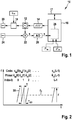
- the in Fig. 1 FMCW radar sensor 10 shown is installed in the front of a motor vehicle. It comprises an oscillator 12 for generating a transmission signal, a frequency modulation device 14 for controlling the frequency of the oscillator 12 and a control and evaluation unit 16 which can be connected to a vehicle bus system 17. An output of the oscillator 12 is connected to a transmit antenna element 20 via a controllable phase modulator 18. Furthermore, an output of the oscillator 12 is connected to a mixer 22. This is configured to mix a received signal received by a receiving antenna element 24 with the frequency-modulated signal of the oscillator 12 in order to generate a baseband signal s. The baseband signal is sampled and digitized by an analog-to-digital converter 26. Mixing and digitizing takes place while maintaining the phase relationships between the received signal and the transmitted signal.
- the control and evaluation unit 16 controls the frequency modulation device 14 and comprises a signal processing unit 28 for evaluating the sample values of the baseband signal s.
- Fig. 2 shows an example of a modulation scheme of the transmission signal output by the oscillator 12 and phase-modulated by the phase modulator 18.
- the frequency f of the transmission signal is plotted as a function of time t.
- the frequency modulation device 14 is set up to modulate the signal of the oscillator 12 in accordance with a chirp sequence modulation with at least one sequence of frequency ramps 30 which follow one another at regular time intervals, in particular a sequence of linear ramps of the same slope, the same center frequency and the same strokes .
- the frequency modulation ramps are also referred to as chirps, frequency ramps or simply as ramps.
- the phase modulator 18 is set up to modulate the phases of the chirps according to a code sequence C m , hereinafter also referred to as code C m .
- code C m a code sequence
- the number of ramps in the sequence is L and is equal to the length of the code C m .
- the chirp sequence modulation and the phase modulation can be synchronized via the vehicle bus 17 with a modulation of a further radar sensor 10 ', so that with the respective sequences of the frequency ramps or respective code sequences the temporal positions of ramps or elements of the sequence corresponding to one another Code sequence have little or no time offset.
- the time offset is less than the duration of a ramp.
- the ramps or elements of the code sequences corresponding to one another in the sequence are used largely overlapping in time, particularly preferably almost simultaneously (i.e. completely overlapping in time).
- the mean frequency of the transmission signal is of the order of 76 gigahertz, and the frequency deviation F of each ramp is of the order of a few megahertz.
- the ramp duration T is in Fig. 2 smaller than the time interval T r2r at which the ramps 30 follow one another. T r2r is on the order of a few microseconds to a few milliseconds.
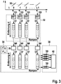
- Fig. 3 shows a block diagram of a method implemented in the signal processing unit 28 for evaluating the baseband signal s.
- a first Fourier transformation 32 takes place in that the sub-signals of the baseband signal s corresponding to the chirps are each subjected to a discrete Fourier transformation 32i in the form of a fast Fourier transformation (FFT) in order to determine a respective complex frequency spectrum 33.
- FFT fast Fourier transformation
- the spectrum 33 contains a peak at a respective frequency position f d .
- the sequence of the chirps 30 results in a harmonic oscillation of the phase of the peak at a constant relative speed v of the located object.
- Their frequency position f v is proportional to the average relative speed v.
- the signal has a phase offset ⁇ m (I) within a ramp 30.
- the one-dimensional frequency spectra 33 are subjected to phase demodulation 34, in which the phase offsets modulated onto the transmission signal are demodulated by opposite phase offsets.
- the ramp index I is demodulated 34i by multiplying the complex spectrum 33 by C * m (I), the conjugate complex of C m (I).
- a second Fourier transformation 38 takes place, for example in the form of a respective FFT 38i, which is carried out for the respective frequency position of the one-dimensional, phase-demodulated spectra 33 ′ corresponding to a distance d via the current ramp index I. Examples are in Fig. 3 the values of the frequency spectra 33 'belonging to a frequency position of the frequency spectra 33' are shown hatched.
- the frequency spectrum calculated with the second FFT shows the peak associated with the respective object at the Doppler frequency f v , corresponding to a peak position (f d , f v ) in the two-dimensional spectrum obtained.
- the further evaluation and object detection is carried out by a detection unit 40.
- the phase demodulation can alternatively take place before the calculation of the first FFT 32.
- the series connection of the first FFT 32 and the second FFT 38 corresponds to a two-dimensional FFT of the phase-demodulated sequence of the radar echoes.
- Fig. 4 1 shows an example in which, by using different code sequences of two FMCW radar sensors 10, 10 'in a motor vehicle 42, self-interference in the form of an interference signal which is received by one radar sensor 10 and comes from the other radar sensor 10' with a transmitting antenna 20 ', is suppressed.
- the radar sensors 10, 10 ' have different installation locations and are in particular mounted separately on the vehicle.
- An interfering signal from a second radar sensor 10 'of the own vehicle is received by an object 46 at a distance of 3.32 m and at a relative speed of 0 m / s, for example a vehicle in front.
- the transmission signals, and in particular the ramp sequences of the radar sensors 10, 10 ′, are synchronized with one another via an on-board vehicle bus system of the motor vehicle 42.
- the first radar sensor 10 uses a code sequence C m for the phase modulation, the second radar sensor 10 'uses a code sequence C q orthogonal thereto.
- the code sequences are also referred to below as codes.
- the cross-correlation function is defined for complex C m , C q as: r Cm .
- I is the time offset and corresponds to the difference between the indices of the values of the respective codes.
- Hadamard codes for example, can be used as orthogonal codes.
- Hadamard codes are binary codes in which the codes of a code set consist of mutually orthogonal lines of Hadamard matrices.
- the elements of a code also referred to as code values, are limited to the values +1 and -1, corresponding to phase offsets of 0 ° and 180 °, respectively.
- the elements of the code can be defined by one bit each.
- the received signal can be regarded as synchronous with the transmitted signal, corresponding to a time offset of zero. This is referred to below as the synchronization condition.
- the correlation sum of the codes is equal to the code length L. This corresponds to the synchronous multiplication of the two codes.
- the cross-correlation function of the two codes for arises as a factor of an amplitude of the second Fourier transformation a time offset equal to zero, r Cm, Cq (0).
- the time offset is equal to 0 when the synchronization condition is fulfilled and the signal originating from the first ramp of the radar sensor 10 ′ is received together with the signal originating from the first ramp of the radar sensor 10.
- the correlation sum is zero.
- an interference signal is a signal originating from the radar sensor 10 ′ and reflected on the object 44.
- interference signals originating directly from the radar sensor 10 ' can also be suppressed. These can correspond, for example, to a dummy object.
- the distance-dependent portion of the frequency dominates in the baseband signal of a ramp, so that the frequency spectrum of the first FFT of a partial signal corresponds to a resolution after the distances d.
- the amplitudes of the frequency spectra of the partial signals are in Fig. 5 schematically plotted over the distance d and over the ramp index I.
- the complex amplitudes in the frequency position of the interfering signal are phase-modulated with the code C q (I).
- the value for the frequency position of the difference signal from the target at a distance of 3.32 m and relative speed 0 m / s is zero, however, since the orthogonality of the codes used results in an amplitude of zero when summing the second FFT.
- An interfering signal from a radar sensor 10 ′′ mounted on the rear of a vehicle 46 in front is received from a distance of 1.66 m at a relative speed of 0 m / s.
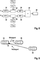
- Fig. 7 shows an example of a transmission signal in which a measuring cycle comprises two partial transmission signals 47, 47 'in the form of nested sequences of frequency ramps 30, 30'.
- the two sequences are also referred to below as ramp sets 47, 47 '.
- the frequency ramps 30 and 30' have an identical ramp stroke, ramp slope and center frequency of the ramps.
- the ramp sets can differ from one another, for example, by a different ramp stroke, a different center frequency and / or a different ramp slope. In the example shown, the ramp sets differ only in the different sign of the ramp slope.
- Each ramp set is phase-modulated with an assigned code sequence of a code set, the code sequence assigning a phase offset to each frequency ramp of the sequence.
- the ramp set 47 (ramps 30) is modulated with a code sequence C m1
- the ramp set 47 '(ramps 30') is modulated with a code sequence C m2 .
- Groups of code sets with this property are also referred to as mutually orthogonal.
- L 512 is described below.
- the signal of the radar sensor 10 is encoded with the code set Cm.
- the signal from the external radar sensor 10 "is encoded with a code set Cq.
- the separation can be implemented, for example, by a time offset, different ramp parameters, and / or by polarization of the antennas used for the individual ramp sets.
- a time offset and a different slope in the form of a different sign of the ramp slope are used.
- the processing initially corresponds to that based on Fig. 3 processing explained.
- the first Fourier transformation 32 is carried out.
- a code set is used which correlates with the code set C m1 , C m2 used for the phase modulation, for example is identical here.
- the phase demodulation 34 is carried out by multiplication by the conjugate complex C * m, 1 or C * m, 2 of the respective code, and the second Fourier transformation 38 is carried out via the ramps of the ramp set in question.
- a summation 48 the two-dimensional spectra of the first set of ramps 47 and the second set of ramps 47 'obtained are added and transferred to the detection unit 40 for further evaluation. Since the distance of a target changes only by a very small value during the time offset of the ramp sets 47, 47 ', the complex amplitudes are added coherently when the two-dimensional frequency spectra are summed.
- Fig. 10 schematically shows, via the ramp index I of an individual ramp set 47 or 47 ', the information about the distance d obtained from the first FFT.
- the signal from the external radar sensor is received by the radar sensor 10 5.12 ms later than the radar echo of the target.
- the respective phase demodulations and the second Fourier transformation 38 are then carried out for the frequency spectra of the respective ramp sets 47, 47 '.
- the two ramp sets each have a two-dimensional spectrum over d and v according to Fig. 11 ,
- ⁇ 01 is a phase offset that depends on the distance of the target.
- the interfering signal is effectively suppressed and the real target can be detected on the basis of the two-dimensional spectrum.
- a code set can be chosen randomly from a group of mutually orthogonal codes.
- different values of at least one parameter of the frequency ramps of the ramp sets 47, 47 ' can be used in successive measurement cycles. If, for example, different ramp slopes are used, the probability is increased that an interfering signal has a different ramp slope than the signal of its own radar sensor. The energy of the interfering signal is then distributed over frequencies in the baseband signal and causes a noise background of the useful signal. For example, different durations or numbers of the ramps of the ramp sets and / or different center frequencies can also be used.
- phase modulation and demodulation each take place with the same code, corresponding to a "matched filter” approach
- code f m or a code set f m1 , f m2 instead for the phase demodulation , which correlates with the code C m , but is not identical, the code set f m1 , f m2 with the at least one further Code set C q meets the code set orthogonality condition.
- Fig. 1 . Fig. 3 and Fig. 8 each indicated by dashed lines.
- the codes f m1 , ??, f mQ corresponding to a linear filter are selected, for example, for a number of Q codes of length L of a code set so that they meet the conditions: r fm 1 . Cm 1 0 + r fm 2 . Cm 2 0 + .... + r fmQ .
- CmQ 0 LQ .
- CqQ i 0
- i i
- phase demodulation of the baseband signal can also be carried out before the first FFT, e.g. the phase demodulation with the code sequences of a code set takes place in separate channels.
- Phase demodulation can also be carried out with the code used in the transmission signal, in that the mixer mixes a received signal with the phase-modulated transmission signal in order to generate the baseband signal.
- Multi-value codes can also be used.
- Binary codes allow a simple circuit design, since for a phase offset of 180 ° only the amplitude of the signal has to be inverted.
- a transmission signal can also be modulated with at least one sequence of frequency ramps that is phase and amplitude modulated according to a code sequence.
- orthogonal codes instead of the Hadamard codes described, other orthogonal codes can also be used, for example Fourier codes.
- the described modulation method with frequency ramps of the same center frequency f 0 according to Fig. 2 or Fig. 7 can be modified by, for example, the center frequency f 0 of the respective within a ramp set or a ramp sequence Ramps is changed according to a linear, higher-level frequency ramp with stroke F slow and ramp duration T slow .
- the frequency f v + f d, slow then corresponds to an FMCW equation for the higher-level ramp.
- the codes described have the advantage that they exist for any code length and that the favorable correlation property is available for each code length. This provides great flexibility in the design of radar signals and radar systems. For example, transmission signals with few ramps can be used. This can result in a shorter transmission time and reduced memory requirements and the data transfer rate of the evaluation unit.
- v and d of an object can be determined.
- a functional relationship between v and d can be determined from a first Fourier analysis of a partial signal assigned to a ramp, for example according to the FMCW equation. Information obtained from the second FFT can then be used to determine v and d, for example, and / or values can be matched over several sequences of ramps with different ramp parameters.
- a respective first Fourier transformation of the respective radar echoes of the frequency ramps of the transmission signal can take place; first information from at least one obtained one-dimensional spectrum in the form of a functional relationship between the distance d and the relative speed v of a located one Object can be determined, the different relative speeds v assigns different distances d, for example, the functional relationship can correspond to an FMCW equation for a respective frequency ramp; at least one second Fourier transformation is carried out in a second dimension over the time course of the sequence of the phase-demodulated, one-dimensional spectra of the radar echoes of the successive frequency ramps; From at least one spectrum obtained from the second Fourier transformation, or, in the case of the partial transmission signals, from the summation of the spectra obtained from the second Fourier transformation, further information about the relative speed and optionally the distance of the located object are obtained, the further information being, for example, information in the form can be a functional relationship according to an FMCW equation for the higher-level, slow ramp of the center frequencies of the frequency ramps
- the comparison of the first information with the second information can take place taking into account an ambiguity of the second information determined by a uniqueness range for the relative speed v and optionally the distance d.
- a method is also called multispeed FMCW (MS-FMCW).
- MS-FMCW multispeed FMCW
- the use of the orthogonal codes or code sets which fulfill the orthogonality condition has the particular advantage that even with MS-FMCW modulation patterns with relatively few, comparatively long ramps, very good suppression of self-interference and / or external interference can be achieved. With a reduced sampling rate of the A / D converter, a good separability of the relative speed v can nevertheless be achieved.
- the spectrum of the second Fourier transformation represents a spectrum of a two-dimensional Fourier analysis, or a sum of two such spectra of the partial transmit signals.
- the distance and the relative speed are thus in particular based on a value of the frequency spectrum of a two-dimensional one Fourier analysis determines, or based on a summation of such two-dimensional frequency spectra.
- the first information can already be determined from a one-dimensional spectrum of a first Fourier transformation.
- the first information from the position of the peak in the first dimension of the frequency spectrum can also be determined on the basis of a peak in the two-dimensional frequency spectrum and the further information can be determined from the position of the peak in the second dimension of the frequency spectrum.
- Fig. 13 shows an example of a vd diagram of first and second information of a ramp sequence of an MS-FMCW measurement with a slow, superordinate frequency ramp of the center frequencies of the short ramps.
- a frequency ramp results instead of a value for d, the straight line which is slightly inclined with respect to the vertical, corresponding to a linear relationship between the relative speed v and the distance d (first information).
- the peak of the spectrum of the second FFT (or the peak of the sum of the spectra of the second FFT) results in a further, here flat, dashed straight line, which is ambiguous.
Description
Die Erfindung betrifft die Bestimmung von Abständen und/oder Relativgeschwindigkeiten von Objekten mit einem FMCW-Radar. Insbesondere betrifft die Erfindung einen FMCW-Radarsensor, ein FMCW-Radarsystem mit einem ersten und wenigstens einem zweiten Radarsensor, sowie ein Radarsystem für eine Fahrzeugflotte, umfassend mehrere FMCW-Radarsensoren.The invention relates to the determination of distances and / or relative speeds of objects with an FMCW radar. In particular, the invention relates to an FMCW radar sensor, an FMCW radar system with a first and at least one second radar sensor, and a radar system for a vehicle fleet comprising a plurality of FMCW radar sensors.
Radarsensoren werden in Kraftfahrzeugen beispielsweise zur Messung der Abstände, Relativgeschwindigkeiten und Azimutwinkel von im Vorfeld des eigenen Fahrzeugs georteten Fahrzeugen oder sonstigen Objekten eingesetzt.Radar sensors are used in motor vehicles, for example, to measure the distances, relative speeds and azimuth angles of vehicles or other objects located in the apron of their own vehicle.
Bei einem FMCW-Radarsensor (Frequency Modulated Continuous Wave) wird die Sendefrequenz eines kontinuierlichen Radarsignals rampenförmig moduliert. Aus einem Empfangssignal wird durch Mischen mit dem Sendesignal ein Basisbandsignal erzeugt, welches dann ausgewertet wird.With an FMCW radar sensor (Frequency Modulated Continuous Wave), the transmission frequency of a continuous radar signal is modulated in a ramp-like manner. A baseband signal is generated from a received signal by mixing with the transmitted signal and is then evaluated.
Es sind FMCW-Radarsensoren bekannt, die nach dem Verfahren der Chirp-Sequence-Modulation arbeiten, bei dem das Sendesignal wenigstens eine Folge gleichartiger Frequenzmodulationsrampen (Chirps) umfasst. Die Modulationsparameter wie die Rampendauer und der Frequenzhub sowie der Zeitabstand zwischen benachbarten Rampen einer Folge sind innerhalb einer Folge gleich. Dabei erfolgt beispielsweise zunächst eine Trennung der Radarobjekte nach ihren Entfernungen, indem eine erste Fouriertransformation des Basisbandsignals jeweils für die einzelnen Frequenzrampen des Sendesignals erfolgt. Anschließend werden die Spektren der ersten Fouriertransformationen der Frequenzrampen einer Folge als Eingangssignal für eine zweite Fouriertransformation verwendet. Somit erfolgt bei der zweiten Fouriertransformation eine Trennung der Radarobjekte nach ihren Geschwindigkeiten anhand von Änderungen der Phasenlagen über die Folge der Radarechos der einzelnen Frequenzrampen.FMCW radar sensors are known which operate according to the chirp sequence modulation method, in which the transmitted signal comprises at least one sequence of similar frequency modulation ramps (chirps). The modulation parameters such as the ramp duration and the frequency swing as well as the time interval between adjacent ramps of a sequence are the same within a sequence. For example, the radar objects are initially separated according to their distances by performing a first Fourier transformation of the baseband signal for the individual frequency ramps of the transmission signal. The spectra of the first Fourier transformations of the frequency ramps of a sequence are then used as an input signal for a second Fourier transformation. Thus, in the second Fourier transformation, the radar objects are separated according to their speeds on the basis of changes in the phase positions via the sequence of the radar echoes of the individual frequency ramps.
Aus
Aus
Gegenwärtig zeichnet sich bei der Entwicklung von Fahrerassistenzsystemen und Sicherheitssystemen für Kraftfahrzeuge die Tendenz ab, dass die Anzahl der in einem Fahrzeug eingesetzten Radarsensoren steigt. Dies erhöht die Wahrscheinlichkeit, dass ein Radarsensor auch ein unerwünschtes, interferierendes Signal eines anderen Radarsensors des gleichen Fahrzeugs empfängt.Currently, there is a tendency in the development of driver assistance systems and safety systems for motor vehicles to increase the number of radar sensors used in a vehicle. This increases the likelihood that a radar sensor will also receive an unwanted interfering signal from another radar sensor of the same vehicle.
Mit einer zunehmenden Verbreitung von Radarsensoren in Kraftfahrzeugen kann in bestimmten Verkehrsszenarien auch ein unerwünschter Empfang von Radarsignalen anderer Fahrzeuge auftreten. So könnte beispielsweise bei einer Kolonnenfahrt ein Heck-Radarsensor eines vorausfahrenden Fahrzeugs einen Frontradarsensor des folgenden Fahrzeugs stören.With the increasing spread of radar sensors in motor vehicles, undesired reception of radar signals from other vehicles can also occur in certain traffic scenarios. For example, when driving in a convoy, a rear radar sensor of a preceding vehicle could interfere with a front radar sensor of the following vehicle.
Aufgabe der Erfindung ist es, ein FMCW-Radarsystem und einen FMCW-Radarsensor mit Chirp-Sequence-Modulation zu schaffen, bei dem unerwünschte Signale anderer Radarsensoren wirksam unterdrückt werden können.The object of the invention is to provide an FMCW radar system and an FMCW radar sensor with chirp sequence modulation, in which unwanted signals from other radar sensors can be effectively suppressed.
Ein Ansatz zur Unterdrückung von interferierenden Signalen anderer Radarsensoren ist ein Versatz der Mittenfrequenzen der Radarsensoren. Dies ist jedoch aufgrund der zur Verfügung stehenden Bandbreite nur beschränkt möglich und führt zu Einbußen in der Entfernungstrennfähigkeit.One approach to suppress interfering signals from other radar sensors is to offset the center frequencies of the radar sensors. However, due to the bandwidth available, this is only possible to a limited extent and leads to losses in the distance separability.
Ein weiterer Ansatz ist die Erkennung von Interferenz im Zeitsignal des Radarsensors basierend auf Interpolation des Zeitsignals. Dabei wird die Modellannahme vorausgesetzt, dass nur ein kleiner Bereich des Zeitsignals gestört ist. Bei Verwendung kurzer Rampendauern oder bei gleichzeitigem Auftreten mehrerer interferierender Signale ist jedoch eine Erkennung der Interferenz und die Interpolation nicht mehr möglich.Another approach is the detection of interference in the time signal of the radar sensor based on interpolation of the time signal. The model assumption is assumed that only a small area of the time signal is disturbed. If short ramp times are used or if several interfering signals occur at the same time, however, interference detection and interpolation are no longer possible.
Die Aufgabe wird erfindungsgemäß durch ein Radarsystem nach Anspruch 1 und einen Radarsensor nach Anspruch 6 gelöst. Weitere Ausführungsformen der Erfindung sind durch die abhängigen Ansprüche definiert. Ausführungsformen, die hier beschrieben werden, und durch die Ansprüche nicht abgedeckt sind, dienen dazu, das Verständnis der Erfindung zu erleichtern. Beispielsweise erfolgt wie bei einer herkömmlichen Chirp-Sequence-Modulation eine Fourieranalyse in Form einer zweidimensionalen, zweistufigen diskreten Fouriertransformation. Eine erste Fouriertransformation bildet eine kohärente, einem entfernungsabhängigen Signalanteil entsprechende Schwingung innerhalb des Radarechos einer Frequenzrampe durch einen Peak im eindimensionalen Spektrum ab. Eine zweite Fouriertransformation wird über die eindimensionalen, hier allerdings zuvor phasendemodulierten Spektren der ersten Fouriertransformation ausgeführt und bildet eine kohärente, einem Doppleranteil entsprechende Schwingung über die Radarechos der Folge der Frequenzrampen durch die Lage des Peaks im Spektrum der zweiten Fouriertransformation ab. Ergebnis der zweidimensionalen Fouriertransformation ist ein zweidimensionales, diskretes oder gerastertes, d.h. in Entfernungs-/Geschwindigkeits-Zellen eingeteiltes, Spektrum. Die Phasendemodulation geschieht vorzugsweise dadurch, dass die eindimensionalen Spektren der Frequenzrampen mit dem jeweiligen konjugiert-komplexen Element der im Empfänger verwendeten Codefolge multipliziert werden. Die zweite Fouriertransformation beinhaltet bereits die Summation der jeweiligen Terme und liefert daher den Wert der Autokorrelation bzw. Kreuzkorrelation als Faktor der Amplitude in der entsprechenden Entfernungs-/Geschwindigkeits-Zelle des zweidimensionalen Spektrums.The object is achieved by a radar system according to
Durch die erfindungsgemäße Phasendemodulation ergibt sich nach der zweiten Fouriertransformation nur dann ein Leistungspeak eines Radarechos, wenn nach der Phasendemodulation eine kohärente Schwingung der Phasenlage der Radarechos über die Folge der Frequenzrampen vorhanden ist. Diese Bedingung erfüllen Radarechos, deren Sendesignal mit der Codefolge phasenmoduliert wurde, die mit der zur Phasendemodulation verwenden Codefolge korreliert. Enthält das Basisbandsignal eines Radarechos hingegen einen Anteil des wenigstens einen zweiten Radarsensors, so haben die entsprechenden, nach der ersten Fouriertransformation erhaltenen Peaks nach der Phasendemodulation keine Kohärenz über die Folge der Frequenzrampen. Die Kreuzkorrelation der Codefolgen liefert hier den Faktor Null.The phase demodulation according to the invention results in a power peak of a radar echo after the second Fourier transformation only if there is a coherent oscillation of the phase position of the radar echoes via the sequence of frequency ramps after the phase demodulation. This condition is met by radar echoes whose transmission signal has been phase-modulated with the code sequence, which correlates with the code sequence used for phase demodulation. However, if the baseband signal of a radar echo contains a portion of the at least one second radar sensor, the corresponding peaks obtained after the first Fourier transformation after phase demodulation have no coherence over the sequence of the frequency ramps. The cross correlation of the code sequences provides the factor zero here.
Besonders vorteilhaft ist, dass durch die Verwendung von zueinander orthogonalen Codefolgen auch bei relativ kurzen Codefolgen eine sehr gute, im Idealfall vollständige Unterdrückung von interferierenden Radarechos von Signalen des anderen Radarsensors erfolgt.It is particularly advantageous that the use of mutually orthogonal code sequences results in a very good, ideally complete suppression of interfering radar echoes from signals of the other radar sensor, even with relatively short code sequences.
Durch die beschriebene Verwendung orthogonaler Codefolgen kann somit bei zeitlich synchronisierter Phasenmodulation zweier Sendesignale eine gegenseitige Interferenz unterdrückt werden. Somit kann Eigeninterferenz innerhalb eines Radarsystems mit mehreren Radarsensoren eines Fahrzeugs unterdrückt werden.Mutual interference can thus be suppressed by the use of orthogonal code sequences described in the case of time-synchronized phase modulation of two transmission signals. Self-interference within a radar system with several radar sensors of a vehicle can thus be suppressed.
Die Aufgabe wird weiter gelöst durch ein Radarsystem nach Anspruch 6.The object is further achieved by a radar system according to
Die getrennte Verarbeitung der Radarechos der Teil-Sendesignale bis zur Bestimmung eines zweidimensionalen Spektrums entspricht beispielsweise jeweils den oben beschriebenen Auswerteschritten.The separate processing of the radar echoes of the partial transmission signals up to the determination of a two-dimensional spectrum corresponds, for example, to the evaluation steps described above.
Durch die Phasendemodulation und Summation der zweidimensionalen Spektren für die Teil-Signale ergibt sich im summierten Spektrum nur dann ein Leistungspeak eines Radarechos, wenn sich die getrennten Spektren zu einem Spektrum addieren, in welchem eine kohärente Schwingung der summierten Phasenlagen der Radarechos über die Folgen der Frequenzrampen vorhanden ist. In der Addition wird im Falle eines Nutzsignals die Summe der Autokorrelationsfunktionen bei Zeitverschiebung Null als Faktor der Amplitude in der entsprechenden Entfernungs-/Geschwindigkeits-Zelle erhalten. Im Falle eines interferierenden, mit einem weiteren Codesatz phasenmodulierten Signals des Radarsensors des anderen Fahrzeugs wird die Summe der Kreuzkorrelationsfunktionen als Faktor der Amplitude erhalten. Diese ist gemäß der Codesatz-Orthogonalitätsbeziehung gleich Null, unabhängig vom Wert einer Zeitverschiebung zwischen den Codefolgen.The phase demodulation and summation of the two-dimensional spectra for the partial signals only result in a power peak of a radar echo in the summed spectrum if the separated spectra add up to a spectrum in which a coherent oscillation of the summed phase positions of the radar echoes over the consequences of the frequency ramps is available. In the addition, in the case of a useful signal, the sum of the autocorrelation functions with zero time shift is obtained as a factor of the amplitude in the corresponding distance / speed cell. In the case of an interfering signal of the radar sensor of the other vehicle that is phase-modulated with a further code set, the sum of the cross-correlation functions is obtained as a factor of the amplitude. According to the code set orthogonality relationship, this is zero, regardless of the value of a time shift between the code sequences.
Durch die beschriebene Verwendung von Codesätzen mit Codefolgen, die die Codesatz-Orthogonalitätsbeziehung erfüllen, kann auch bei zeitlich nicht synchronisierter Phasenmodulation zweier Sendesignale eine gegenseitige Interferenz unterdrückt werden. Somit kann Fremdinterferenz zwischen Radarsensoren zweier Fahrzeuge unterdrückt werden.The described use of code sets with code sequences which fulfill the code set-orthogonality relationship means that mutual interference can be suppressed even when phase modulation of two transmission signals is not synchronized in time. External interference between radar sensors of two vehicles can thus be suppressed.
Weitere vorteilhafte Ausgestaltungen und Weiterbildungen der Erfindung sind in den Unteransprüchen angegeben.Further advantageous refinements and developments of the invention are specified in the subclaims.
Im Folgenden werden Ausführungsbeispiele anhand der Zeichnung näher erläutert.Exemplary embodiments are explained in more detail below with reference to the drawing.
Es zeigen:
- Fig. 1
- ein Blockdiagramm eines FMCW-Radarsensors;
- Fig. 2
- eine schematische Darstellung einer Folge von Frequenzmodulationsrampen eines Sendesignals;
- Fig. 3
- ein Blockdiagramm zur Erläuterung der Auswertung eines Basisbandsignals;
- Fig. 4
- eine schematische Darstellung eines Kraftfahrzeugs mit einem FMCW-Radarsystem in einer Situation mit Eigen-Interferenz;
- Fig. 5
- ein Diagramm, das Abstandsinformation aus Teilsignalen eines Basisbandsignals zeigt, zur Erläuterung der Auswertung nach
Fig. 3 ; - Fig. 6
- ein Diagramm, das Geschwindigkeits- und Abstandsinformation aus einem Signalverlauf über die Teilsignale zeigt, zur Erläuterung der Auswertung nach
Fig. 3 ; - Fig. 7
- eine beispielhafte Darstellung eines Sendesignals mit zwei Teil-Sendesignalen in Form einer jeweiligen Folge von Frequenzmodulationsrampen, zur Erläuterung einer Phasendemodulation bei Verwendung von Codesätzen mit mehreren Codes;
- Fig. 8
- ein Blockdiagramm zur Erläuterung der Auswertung eines Basisbandsignals bei einem Sendesignal mit zwei Rampensätzen wie z.B. nach
Fig. 7 ; - Fig. 9
- eine schematische Darstellung eines Kraftfahrzeugs mit einem FMCW-Radarsystem in einer Situation mit Fremd-Interferenz;
- Fig. 10
- ein Diagramm, das Abstandsinformation aus Teilsignalen eines Basisbandsignals in einem Rampensatz zeigt, zur Erläuterung der Auswertung nach
Fig. 8 ; - Fig. 11
- ein Diagramm, das Geschwindigkeits- und Abstandsinformation aus Signalverläufen über Folgen von Teilsignalen in einem Rampensatz zeigt, zur Erläuterung der Auswertung nach
Fig. 8 ; - Fig. 12
- ein Abstands-Geschwindigkeits-Diagramm nach der Summation von Signalverarbeitungsergebnissen für die beiden Rampensätze, zur Erläuterung der Auswertung nach
Fig. 8 ; und - Fig. 13
- ein Abstands-Geschwindigkeits-Diagramm zur Erläuterung der Auswertung von Multispeed-FMCW-Radarsignalen.
- Fig. 1
- a block diagram of an FMCW radar sensor;
- Fig. 2
- a schematic representation of a sequence of frequency modulation ramps of a transmission signal;
- Fig. 3
- a block diagram for explaining the evaluation of a baseband signal;
- Fig. 4
- a schematic representation of a motor vehicle with an FMCW radar system in a situation with self-interference;
- Fig. 5
- a diagram showing distance information from partial signals of a baseband signal to explain the evaluation
Fig. 3 ; - Fig. 6
- a diagram showing speed and distance information from a waveform over the partial signals to explain the evaluation
Fig. 3 ; - Fig. 7
- an exemplary representation of a transmission signal with two partial transmission signals in the form of a respective sequence of frequency modulation ramps, to explain phase demodulation when using code sets with several codes;
- Fig. 8
- a block diagram for explaining the evaluation of a baseband signal in a transmission signal with two ramp sets such as after
Fig. 7 ; - Fig. 9
- a schematic representation of a motor vehicle with an FMCW radar system in a situation with external interference;
- Fig. 10
- a diagram showing distance information from partial signals of a baseband signal in a ramp set to explain the evaluation
Fig. 8 ; - Fig. 11
- a diagram that shows speed and distance information from signal curves about sequences of partial signals in a ramp set to explain the evaluation
Fig. 8 ; - Fig. 12
- a distance-speed diagram after the summation of signal processing results for the two ramp sets, to explain the evaluation after
Fig. 8 ; and - Fig. 13
- a distance-speed diagram to explain the evaluation of multispeed FMCW radar signals.
Der in
Die Frequenzmodulationseinrichtung 14 ist dazu eingerichtet, im einem Messzyklus das Signal des Oszillators 12 entsprechend einer Chirp-Sequence-Modulation mit wenigstens einer Folge von in regelmäßigen Zeitabständen aufeinanderfolgenden Frequenzrampen 30 zu modulieren, insbesondere einer Folge von linearen Rampen gleicher Steigung, gleicher Mittenfrequenz und gleichen Hubs. Die Frequenzmodulationsrampen werden auch als Chirps, Frequenzrampen oder einfach als Rampen bezeichnet.The
Der Phasenmodulator 18 ist dazu eingerichtet, die Phasen der Chirps gemäß einer Codefolge Cm zu modulieren, nachfolgend auch als Code Cm bezeichnet. Dabei erhält jeder Chirp mit Index I, I=0,...,L-1, innerhalb der Folge eine Phasenlage gemäß einem zugeordneten Element der Codefolge in Form einer Phase φm(I). Dies kann als Multiplikation der komplexen Amplitude mit dem Faktor Cm (l) = e jφm (l) beschrieben werden, wobei j die imaginäre Einheit ist. Die Anzahl der Rampen der Folge beträgt L und ist gleich der Länge des Codes Cm.The
Die Chirp-Sequence-Modulation und die Phasenmodulation sind über den Fahrzeugbus 17 mit einer Modulation eines weiteren Radarsensors 10' synchronisierbar, so dass bei den jeweiligen Folgen der Frequenzrampen bzw. jeweiligen Codefolgen die zeitlichen Lagen von einander in der Reihenfolge entsprechenden Rampen bzw. Elementen der Codefolge nur einen geringen oder keinen Zeitversatz haben. Der Zeitversatz ist kleiner als die Dauer einer Rampe. Vorzugsweise werden die einander in der Reihenfolge entsprechenden Rampen bzw. Elemente der Codefolgen größtenteils zeitlich überlappend, besonders bevorzugt nahezu gleichzeitig (d.h. zeitlich vollständig überlappend) verwendet.The chirp sequence modulation and the phase modulation can be synchronized via the
Die mittlere Frequenz des Sendesignals liegt in der Größenordnung von 76 Gigahertz, und der Frequenzhub F jeder Rampe liegt in der Größenordnung von einigen Megahertz. Die Rampendauer T ist in
Eine erste Fouriertransformation 32 erfolgt, indem die den Chirps entsprechenden Teil-signale des Basisbandsignals s jeweils einer diskreten Fouriertransformation 32i in Form einer schnellen Fouriertransformation (FFT) unterzogen werden, um ein jeweiliges komplexes Frequenzspektrum 33 zu bestimmen. Für ein geortetes Objekt enthält das Spektrum 33 einen Peak bei einer jeweiligen Frequenzlage fd.A
Über die Folge der Chirps 30 ergibt sich bei konstanter Relativgeschwindigkeit v des georteten Objekts eine harmonische Schwingung der Phase des Peaks. Deren Frequenzlage fv ist proportional zur mittleren Relativgeschwindigkeit v. Zusätzlich weist das Signal innerhalb einer Rampe 30 den Phasenoffset φm(I) auf.The sequence of the
Nach der ersten FFT 32 werden die eindimensionalen Frequenzspektren 33 einer Phasendemodulation 34 unterzogen, bei der die dem Sendesignal aufmodulierten Phasenoffsets durch entgegengesetzte Phasenoffsets demoduliert werden. Zum Rampenindex I erfolgt eine jeweilige Demodulation 34i durch Multiplikation des komplexen Spektrums 33 mit C*m(I), dem konjugiert-komplexen von Cm(I).After the
Es erfolgt eine zweite Fouriertransformation 38, beispielsweise in Form einer jeweiligen FFT 38i, die für einen jeweilige, einer Entfernung d entsprechende Frequenzlage der eindimensionalen, phasendemodulierten Spektren 33' über den laufenden Rampenindex I ausgeführt wird. Beispielhaft sind in
Bei der Frequenzlage fd der ersten FFT zeigt das mit der zweiten FFT berechnete Frequenzspektrum den dem jeweiligen Objekt zugeordneten Peak bei der Dopplerfrequenz fv, entsprechend einer Peak-Lage (fd, fv) im erhaltenen zweidimensionalen Spektrum. Die weitere Auswertung und Objektdetektion erfolgt durch eine Detektionseinheit 40.At the frequency position f d of the first FFT, the frequency spectrum calculated with the second FFT shows the peak associated with the respective object at the Doppler frequency f v , corresponding to a peak position (f d , f v ) in the two-dimensional spectrum obtained. The further evaluation and object detection is carried out by a
Die Phasendemodulation kann alternativ bereits vor der Berechnung der ersten FFT 32 erfolgen. Die Hintereinanderschaltung der ersten FFT 32 und der zweiten FFT 38 entspricht einer zweidimensionalen FFT der phasendemodulierten Folge der Radarechos.The phase demodulation can alternatively take place before the calculation of the
Im Beispiel befindet sich ein Radarobjekt 44 auf einer Nebenspur bei einer Entfernung d = 42 m und hat eine Relativgeschwindigkeit von v = -7,6 m/s. Ein interferierendes Signal aus einem zweiten Radarsensor 10' des eigenen Fahrzeugs wird von einem Objekt 46 in einer Entfernung von 3,32 m und mit einer Relativgeschwindigkeit von 0 m/s empfangen, beispielsweise einem vorausfahrenden Fahrzeug. Die Sendesignale, und insbesondere die Rampenfolgen der Radarsensoren 10, 10', sind über ein bordeigenes Fahrzeugbussystem des Kraftfahrzeuges 42 miteinander synchronisiert.In the example, a
Der erste Radarsensor 10 verwendet für die Phasenmodulation eine Codefolge Cm, der zweite Radarsensor 10' eine dazu orthogonale Codefolge Cq. Die Codefolgen werden nachfolgend auch als Codes bezeichnet.The
Codes werden als orthogonal bezeichnet, wenn ihre Kreuzkorrelationsfunktion für ein einen Zeitversatz Null gleich Null ist, d.h. rCm,Cq(0) = 0. Die Kreuzkorrelationsfunktion ist für komplexe Cm, Cq definiert als: ![]()
![]()
Als orthogonale Codes können beispielsweise Hadamard-Codes verwendet werden. Hadamard-Codes sind binäre Codes, bei denen die Codes eines Codesatzes aus zueinander orthogonalen Zeilen von Hadamard-Matrizen bestehen. Die Elemente eines Codes, auch als Codewerte bezeichnet, sind auf die Werte +1 und -1 beschränkt, entsprechend Phasenoffsets von 0° bzw. 180°. Im Falle eines binären Codes können die Elemente des Codes durch jeweils ein Bit definiert werden.Hadamard codes, for example, can be used as orthogonal codes. Hadamard codes are binary codes in which the codes of a code set consist of mutually orthogonal lines of Hadamard matrices. The elements of a code, also referred to as code values, are limited to the values +1 and -1, corresponding to phase offsets of 0 ° and 180 °, respectively. In the case of a binary code, the elements of the code can be defined by one bit each.
Für jede Rampe wird das Spektrum nach der ersten FFT mit dem konjugiert komplexen des zugeordneten Elements der Codefolge multipliziert.For each ramp, the spectrum after the first FFT is multiplied by the conjugate complex of the assigned element of the code sequence.
Da die Dauer einer Rampe sehr viel größer als die Laufzeit des Signals zu einem realen Ziel und zurück ist, kann das empfangene Signal als synchron zu dem gesendeten Signal angesehen werden, entsprechend einem Zeitversatz Null. Dies wird im Folgenden als Synchronisationsbedingung bezeichnet.Since the duration of a ramp is much longer than the transit time of the signal to a real destination and back, the received signal can be regarded as synchronous with the transmitted signal, corresponding to a time offset of zero. This is referred to below as the synchronization condition.
Nach Durchführung der zweiten FFT über die Rampen ergibt sich für den Peak bei der Dopplerfrequenz fv eine Amplitude, die proportional ist zum Wert der Kreuzkorrelationsfunktion des verwendeten Codes mit Zeitversatz Null, rCm,Cm(0) = L. Die Korrelationssumme der Codes ist gleich der Codelänge L. Dies entspricht der synchronen Multiplikation der beiden Codes. Insgesamt ist die Amplitude durch die Integration der 1. FFT über K Samples pro Rampe und die Integration der 2. FFT über die L Rampen einer Folger um einen Faktor KL größer als die Amplitude des Empfangssignals.After performing the second FFT over the ramps, the amplitude at the Doppler frequency f v is proportional to the value of the cross-correlation function of the code used with a time offset of zero, r Cm, Cm (0) = L. The correlation sum of the codes is equal to the code length L. This corresponds to the synchronous multiplication of the two codes. Overall, the integration of the 1st FFT via K samples per ramp and the integration of the 2nd FFT via the L ramps of a follower increase the amplitude by a factor KL than the amplitude of the received signal.
Wird ein interferierendes Signal von dem zweiten Radarsensor 10' empfangen, das mit dem Code Cq kodiert wurde, so ergibt sich nach der ersten Fouriertransformation und der Phasendemodulation mit dem Code Cm hingegen als Vorfaktor einer Amplitude der zweiten Fouriertransformation die Kreuzkorrelationsfunktion der beiden Codes für einen Zeitversatz gleich Null, rCm,Cq(0). Dabei ist der Zeitversatz gleich 0, wenn die Synchronisationsbedingung erfüllt ist und somit das von der ersten Rampe des Radarsensors 10' stammende Signal zusammen mit dem von der ersten Rampe des Radarsensors 10 stammenden Signal empfangen wird. Aufgrund der Orthogonalität rCm,Cq(0)=0 der beiden Codes wird die Störung unterdrückt. Die Korrelationssumme ist Null.If an interfering signal is received by the
Im Beispiel ist ein Störsignal ein vom Radarsensor 10' stammendes, am Objekt 44 reflektiertes Signal. Es können aber auch direkt vom Radarsensor 10' stammende Störsignale unterdrückt werden. Diese können beispielsweise einem Scheinobjekt entsprechen.In the example, an interference signal is a signal originating from the
Die in
Aufgrund der Kürze und Steilheit der Rampen dominiert im Basisbandsignal einer Rampe der abstandsabhängige Anteil der Frequenz, so dass das Frequenzspektrum der ersten FFT eines Teilsignals einer Auflösung nach den Entfernungen d entspricht. Die Amplituden der Frequenzspektren der Teilsignale sind in
Die Werte der komplexen Amplitude bei der Frequenzlage entsprechend dem Abstand d = 42 m sind dabei über die Folge der Rampen I mit dem Code Cm(I) phasenmoduliert. Hingegen sind die komplexen Amplituden bei der Frequenzlage des interferierenden Signals mit dem Code Cq(I) phasenmoduliert.The values of the complex amplitude at the frequency position corresponding to the distance d = 42 m are phase-modulated via the sequence of ramps I with the code C m (I). In contrast, the complex amplitudes in the frequency position of the interfering signal are phase-modulated with the code C q (I).
Nach der Phasendemodulation mit dem Code Cm und der zweiten FFT weist das zweidimensionale Spektrum einen einzigen Peak bei der Frequenzlage des realen Objektes entsprechend d = 42 m und v = -6,7 m/s auf, wie in
Wenn bei kurzer Rampenzeit die Synchronisationsbedingung nicht erfüllt ist, so ergibt sich als Vorfaktor des Interferenzsignals nach der zweiten FFT die Kreuzkorrelationsfunktion der Codes mit einem Zeitversatz ungleich Null. Diese ist im Normalfall nicht Null. Sie ist jedoch beispielsweise bei Verwendung von zwei Hadamard-Codes mit der Codelänge L=512 um log10(1/512) = 27dB kleiner als der Vorfaktor L = 512 der Amplitude des Nutzsignals. Somit wird auch bei einem geringen Zeitversatz, der die Länge einer Rampe übersteigt, das interferierende Signal wirksam unterdrückt.If the synchronization condition is not fulfilled with a short ramp time, the pre-factor of the interference signal after the second FFT is the cross-correlation function of the codes with a time offset other than zero. This is usually not zero. However, if two Hadamard codes with the code length L = 512 are used, it is, for example, 10 (1/512) = 27dB smaller than the pre-factor L = 512 of the amplitude of the useful signal. Thus, even with a small time offset that exceeds the length of a ramp, the interfering signal is effectively suppressed.
Anhand von
Jeder Rampensatz wird mit einer zugeordneten Codefolge eines Codesatzes phasenmoduliert, wobei die Codefolge jeder Frequenzrampe der Folge einen Phasenoffset zuordnet. Der Rampensatz 47 (Rampen 30) wird mit einer Codefolge Cm1 moduliert, und der Rampensatz 47' (Rampen 30') wird mit einer Codefolge Cm2 moduliert.Each ramp set is phase-modulated with an assigned code sequence of a code set, the code sequence assigning a phase offset to each frequency ramp of the sequence. The ramp set 47 (ramps 30) is modulated with a code sequence C m1 , and the ramp set 47 '(ramps 30') is modulated with a code sequence C m2 .
Der Codesatz Cm mit den Codes Cm1 und Cm2 wird aus einer Codegruppe gewählt, die M Codesätze enthält, wobei jeder Codesatz Q Codes der Länge L hat, wobei Q der Anzahl der Rampensätze entspricht und größer oder gleich 2 ist, im Beispiel Q=2. Es wird eine Codegruppe gewählt, die die als Codesatz-Orthogonalitätsbedingung bezeichnete Eigenschaft für alle Paare von Codesätzen Cm und Cq erfüllt: ![]()
![]()
Gruppen von Codesätzen mit dieser Eigenschaft werden auch als gegenseitig orthogonal ("mutually orthogonal") bezeichnet.Groups of code sets with this property are also referred to as mutually orthogonal.
Zur Veranschaulichung wird ein Beispiel mit L = 16 und einer Anzahl von M = 2 Codesätzen C1,C2 mit jeweils Q = 2 Codes C11,C12 bzw. C21,C22 gegeben: 
Die Codesätze erfüllen die Eigenschaft der gegenseitigen Orthogonalität: ![]()
![]()
Im Folgenden wird ein Beispiel mit L=512 beschrieben. Das Signal des Radarsensors 10 ist mit dem Codesatz Cm kodiert. Das Signal des fremden Radarsensors 10" ist mit einem Codesatz Cq kodiert.An example with L = 512 is described below. The signal of the
Die zu den beiden Rampensätzen 47, 47' empfangenen Signale werden zunächst getrennt in einem jeweiligen Kanal verarbeitet, wie in
Im jeweiligen Kanal entspricht die Verarbeitung zunächst der anhand von
In einer Summation 48 werden die erhaltenen zweidimensionalen Spektren des ersten Rampensatzes 47 und des zweiten Rampensatzes 47' addiert und zur weiteren Auswertung an die Detektionseinheit 40 übergeben. Da die Entfernung eines Ziels sich während des Zeitversatzes der Rampensätze 47, 47' nur um einen sehr geringen Wert ändert, werden bei der Summation der zweidimensionalen Frequenzspektren die komplexen Amplituden kohärent addiert.In a
Für den Fall eines realen Ziels entsteht bei der Frequenzlage des Ziels in den Frequenzspektren des Basisbandsignals bei der zweiten FFT 38 für einen jeweiligen Rampensatz eine Amplitude, die proportional zur Autokorrelationsfunktion des jeweiligen Codes mit Zeitversatz Null ist. Die Korrelationssumme der Codes ist für den jeweiligen Rampensatz daher gleich der Codelänge L.In the case of a real target, an amplitude arises in the frequency position of the target in the frequency spectra of the baseband signal in the
Nach Summation der zweidimensionalen Spektren der Rampensätze 47, 47' ergibt sich ein Peak mit der Amplitude des Betrags 2ANfastL. Die Amplitude ist somit proportional einer Summe der Korrelationssummen der Codes des Codesatzes.After summation of the two-dimensional spectra of the ramp sets 47, 47 ', there is a peak with the amplitude of the amount 2AN almost L. The amplitude is thus proportional to a sum of the correlation sums of the codes of the code set.
Bei einer Frequenz des interferierenden Signals eines fremden Radarsensors, der mit dem Codesatz Cq1, Cq2 kodiert ist, ergibt sich bei der Summe der zweidimensionalen Spektren jedoch jeweils eine Amplitude, die proportional ist zur Summe der Kreuzkorrelationsfunktionen der jeweiligen Codes der Codesätze mit einem Zeitversatz, der gleich Null oder ungleich Null sein kann. Aufgrund der Eigenschaft der gegenseitigen Orthogonalität gemäß Gleichung (2) ist diese stets Null.At a frequency of the interfering signal of an external radar sensor that is coded with the code set C q1 , C q2 , however, the sum of the two-dimensional spectra results in an amplitude that is proportional to the sum of the cross-correlation functions of the respective codes of the code sets with a time offset which can be zero or non-zero. Due to the property of mutual orthogonality according to equation (2), this is always zero.
Für die Frequenzspektren der jeweiligen Rampensätze 47, 47' werden dann die jeweiligen Phasendemodulationen und die zweite Fouriertransformation 38 durchgeführt. Es ergibt sich für die beiden Rampensätze jeweils ein zweidimensionales Spektrum über d und v gemäß
Nach Summation der Spektren ergibt sich ein Spektrum gemäß ![]()
![]()
Dabei ist φ01 ein Phasenoffset, der von der Entfernung des Ziels abhängig ist.Φ 01 is a phase offset that depends on the distance of the target.
Somit wird das interferierende Signal wirksam unterdrückt, und das reale Ziel kann anhand des zweidimensionalen Spektrums detektiert werden.Thus, the interfering signal is effectively suppressed and the real target can be detected on the basis of the two-dimensional spectrum.
In einer Variante des beschriebenen Verfahrens mit gegenseitig orthogonalen Codes werden für aufeinanderfolgende Messzyklen unterschiedliche Codesätze verwendet. Beispielsweise kann ein Codesatz zufällig aus einer Gruppe gegenseitig orthogonaler Codes gewählt werden. Somit wird bei einer Interferenz von Signalen von Radarsensoren zweier Fahrzeuge, die dieselbe Codegruppe verwenden, die Wahrscheinlichkeit verringert, dass die Fahrzeuge gleichzeitig dieselbe Codierung verwenden.In a variant of the described method with mutually orthogonal codes, different code sets are used for successive measurement cycles. For example, a code set can be chosen randomly from a group of mutually orthogonal codes. Thus, if signals from radar sensors of two vehicles using the same code group interfere, the probability that the vehicles use the same coding at the same time is reduced.
Zur weiteren Verringerung der Auswirkung von Fremd-Interferenz können in aufeinanderfolgenden Messzyklen unterschiedliche Werte wenigstens eines Parameters der Frequenzrampen der Rampensätze 47, 47' verwendet werden. Werden beispielsweise unterschiedliche Rampensteigungen verwendet, so wird die Wahrscheinlichkeit erhöht, dass ein interferierendes Signal eine andere Rampensteigung als das Signal des eigenen Radarsensors hat. Die Energie des interferierendes Signals verteilt sich dann im Basisbandsignal über Frequenzen und bewirkt einen Rauschhintergrund des Nutzsignals. Es können beispielsweise auch unterschiedliche Dauern oder Anzahlen der Rampen der Rampensätze und/oder unterschiedliche Mittenfrequenzen verwendet werden.To further reduce the effect of external interference, different values of at least one parameter of the frequency ramps of the ramp sets 47, 47 'can be used in successive measurement cycles. If, for example, different ramp slopes are used, the probability is increased that an interfering signal has a different ramp slope than the signal of its own radar sensor. The energy of the interfering signal is then distributed over frequencies in the baseband signal and causes a noise background of the useful signal. For example, different durations or numbers of the ramps of the ramp sets and / or different center frequencies can also be used.
Während bei den oben beschriebenen Beispielen die Phasenmodulation und - demodulation jeweils mit demselben Code erfolgt, entsprechend einem "Matched Filter"-Ansatz, ist es auch denkbar, stattdessen für die Phasendemodulation einen Code fm bzw. einen Codesatz fm1, fm2 zu verwenden, der mit dem Code Cm korreliert, aber nicht identisch ist, wobei der Codesatz fm1, fm2 mit dem wenigstens einen weiteren Codesatz Cq die Codesatz-Orthogonalitätsbedingung erfüllt. Dies ist in ![]()
![]()
![]()
![]()
Dadurch steht eine größere Anzahl von Codesätzen zur Verfügung.This means that a larger number of code sets is available.
Anders als beschrieben kann die Phasendemodulation des Basisbandsignals auch vor der ersten FFT durchgeführt werden, wobei z.B. die Phasendemodulation mit den Codefolgen eines Codesatzes in getrennten Kanälen erfolgt.Unlike described, the phase demodulation of the baseband signal can also be carried out before the first FFT, e.g. the phase demodulation with the code sequences of a code set takes place in separate channels.
Auch kann eine Phasendemodulation mit dem beim Sendesignal verwendeten Code erfolgen, indem der Mischer ein empfangenes Signal mit dem phasenmodulierten Sendesignal mischt, um das Basisbandsignal zu erzeugen.Phase demodulation can also be carried out with the code used in the transmission signal, in that the mixer mixes a received signal with the phase-modulated transmission signal in order to generate the baseband signal.
Es können auch mehrwertige Codes verwendet werden. Binäre Codes ermöglichen jedoch einen schaltungstechnisch einfachen Aufbau, da für einen Phasenoffset von 180° lediglich die Amplitude des Signals zu invertieren ist.Multi-value codes can also be used. Binary codes, however, allow a simple circuit design, since for a phase offset of 180 ° only the amplitude of the signal has to be inverted.
In den beschriebenen Beispielen erfolgt lediglich eine Phasenmodulation, jedoch keine Amplitudenmodulation, so dass die volle Signalstärke genutzt werden kann. Ein Sendesignal kann jedoch auch mit wenigstens einer gemäß einer Codefolge phasen- und amplitudenmodulierten Folge von Frequenzrampen moduliert werden.In the examples described, only phase modulation takes place, but no amplitude modulation, so that the full signal strength can be used. However, a transmission signal can also be modulated with at least one sequence of frequency ramps that is phase and amplitude modulated according to a code sequence.
Anstelle der beschriebenen Hadamard-Codes können auch andere orthogonale Codes verwendet werden, beispielsweise Fourier-Codes.Instead of the Hadamard codes described, other orthogonal codes can also be used, for example Fourier codes.
Das beschriebene Modulationsverfahren mit Frequenzrampen gleicher Mittenfrequenz f0 gemäß
Die beschriebenen Codes haben den Vorteil, dass sie für beliebige Codelängen existieren und die günstige Korrelationseigenschaft für jede Codelänge vorhanden ist. Somit wird eine große Flexibilität beim Entwurf von Radarsignalen und Radarsystemen zur Verfügung gestellt. Es können beispielsweise Sendesignale mit wenigen Rampen verwendet werden. Daraus können sich eine geringere Sendezeit und verringerte Anforderungen an Speicher und die Datenübertragungsrate der Auswerteeinheit ergeben.The codes described have the advantage that they exist for any code length and that the favorable correlation property is available for each code length. This provides great flexibility in the design of radar signals and radar systems. For example, transmission signals with few ramps can be used. This can result in a shorter transmission time and reduced memory requirements and the data transfer rate of the evaluation unit.
Bei den beschriebenen Modulationsverfahren werden kurze, schnelle Frequenzrampen verwendet, so dass die Frequenzspektren der den Rampen entsprechenden Teilsignale von dem abstandsabhängigen Frequenzanteil dominiert werden. Es sind aber auch modifizierte Verfahren denkbar, um eine Bestimmung von Werten für v und d eines Objektes zu ermöglichen. Dabei können beispielsweise Rampen mit geringerer Steigung und/oder größerer Rampendauer von z.B. T = 0,1 ms verwendet werden, wodurch auch die Anforderungen an die Abtastrate und/oder die Frequenzmodulation verringert werden. So kann beispielsweise aus einer ersten Fourieranalyse eines einer Rampe zugeordneten Teilsignals ein funktionaler Zusammenhang zwischen v und d ermittelt werden, beispielsweise gemäß der FMCW-Gleichung. Zur Bestimmung von v und d kann dann beispielsweise aus der zweiten FFT erhaltene Information verwendet werden und/oder ein Matching von Werten über mehrere Folgen von Rampen unterschiedlicher Rampenparameter erfolgen.In the described modulation methods, short, fast frequency ramps are used, so that the frequency spectra of the partial signals corresponding to the ramps are dominated by the distance-dependent frequency component. However, modified methods are also conceivable to enable values for v and d of an object to be determined. For example, ramps with a lower gradient and / or longer ramp times of e.g. T = 0.1 ms can be used, which also reduces the requirements for the sampling rate and / or the frequency modulation. For example, a functional relationship between v and d can be determined from a first Fourier analysis of a partial signal assigned to a ramp, for example according to the FMCW equation. Information obtained from the second FFT can then be used to determine v and d, for example, and / or values can be matched over several sequences of ramps with different ramp parameters.
Beispielsweise kann eine jeweilige erste Fouriertransformation der jeweiligen Radarechos der Frequenzrampen des Sendesignals erfolgen; aus wenigstens einem erhaltenen eindimensionalen Spektrum erste Information in Form eines funktionalen Zusammenhangs zwischen dem Abstand d und der Relativgeschwindigkeit v eines georteten Objekts bestimmt werden, der unterschiedlichen Relativgeschwindigkeiten v unterschiedliche Abstände d zuordnet, wobei beispielsweise der funktionale Zusammenhang einer FMCW-Gleichung für eine jeweilige Frequenzrampe entsprechen kann; wenigstens eine zweite Fouriertransformation in einer zweiten Dimension über den zeitlichen Verlauf der Folge der phasendemodulierten, eindimensionalen Spektren der Radarechos der aufeinanderfolgenden Frequenzrampen ausgeführt werden; aus wenigstens einem erhaltenen Spektrum der zweiten Fouriertransformation, bzw., im Falle der Teil-Sendesignale, aus der Summation der erhaltenen Spektren der zweiten Fouriertransformation, weitere Information über Relativgeschwindigkeit und optional Abstand des georteten Objekts erhalten werden, wobei die weitere Information beispielsweise Information in Form eines funktionalen Zusammenhangs gemäß einer FMCW-Gleichung für die übergeordnete, langsame Rampe der Mittenfrequenzen der Frequenzrampen sein kann; und der Abstand d und die Relativgeschwindigkeit v des georteten Objekts basierend auf einem Abgleichen (auch als Matching bezeichnet) der ersten Information mit der weiteren Information bestimmt werden. Beispielsweise kann das Abgleichen der ersten Information mit der zweiten Information unter Berücksichtigung einer durch einen Eindeutigkeitsbereich für die Relativgeschwindigkeit v und optional den Abstand d bestimmten Mehrdeutigkeit der zweiten Information erfolgen. Ein solches Verfahren wird auch als Multispeed-FMCW (MS-FMCW) bezeichnet. Dabei hat die Verwendung der orthogonalen Codes oder Codesätze, die Orthogonalitätsbedingung erfüllen, den besonderen Vorteil, dass auch bei MS-FMCW-Modulationsmustern mit relativ wenigen, vergleichsweise langen Rampen eine sehr gute Unterdrückung von Eigeninterferenz und/oder Fremdinterferenz erreichen lässt. Es lässt sich somit bei einer verringerten Abtastrate des A/D-Wandlers dennoch eine gute Trennfähigkeit der Relativgeschwindigkeit v erreichen.For example, a respective first Fourier transformation of the respective radar echoes of the frequency ramps of the transmission signal can take place; first information from at least one obtained one-dimensional spectrum in the form of a functional relationship between the distance d and the relative speed v of a located one Object can be determined, the different relative speeds v assigns different distances d, for example, the functional relationship can correspond to an FMCW equation for a respective frequency ramp; at least one second Fourier transformation is carried out in a second dimension over the time course of the sequence of the phase-demodulated, one-dimensional spectra of the radar echoes of the successive frequency ramps; From at least one spectrum obtained from the second Fourier transformation, or, in the case of the partial transmission signals, from the summation of the spectra obtained from the second Fourier transformation, further information about the relative speed and optionally the distance of the located object are obtained, the further information being, for example, information in the form can be a functional relationship according to an FMCW equation for the higher-level, slow ramp of the center frequencies of the frequency ramps; and the distance d and the relative speed v of the located object are determined based on a comparison (also referred to as matching) of the first information with the further information. For example, the comparison of the first information with the second information can take place taking into account an ambiguity of the second information determined by a uniqueness range for the relative speed v and optionally the distance d. Such a method is also called multispeed FMCW (MS-FMCW). The use of the orthogonal codes or code sets which fulfill the orthogonality condition has the particular advantage that even with MS-FMCW modulation patterns with relatively few, comparatively long ramps, very good suppression of self-interference and / or external interference can be achieved. With a reduced sampling rate of the A / D converter, a good separability of the relative speed v can nevertheless be achieved.
Durch die Hintereinanderausführung der eindimensionalen ersten und zweiten Fouriertransformationen stellt das Spektrum der zweiten Fouriertransformation ein Spektrum einer zweidimensionalen Fourieranalyse dar, bzw. eine Summe zweier solcher Spektren der Teil-Sendesignale. Der Abstand und die Relativgeschwindigkeit werden somit insbesondere anhand eines Wertes des Frequenzspektrums einer zweidimensionalen Fourieranalyse bestimmt, bzw. anhand einer Summation solcher zweidimensionaler Frequenzspektren.By executing the one-dimensional first and second Fourier transformations in series, the spectrum of the second Fourier transformation represents a spectrum of a two-dimensional Fourier analysis, or a sum of two such spectra of the partial transmit signals. The distance and the relative speed are thus in particular based on a value of the frequency spectrum of a two-dimensional one Fourier analysis determines, or based on a summation of such two-dimensional frequency spectra.
Die erste Information kann bereits aus einem eindimensionalen Spektrum einer ersten Fouriertransformation bestimmt werden. Es kann auch anhand eines Peaks im zweidimensionalen Frequenzspektrum die erste Information aus der Lage des Peaks in der ersten Dimension des Frequenzspektrums bestimmt werden und die weitere Information aus der Lage des Peaks in der zweiten Dimension des Frequenzspektrums bestimmt werden.The first information can already be determined from a one-dimensional spectrum of a first Fourier transformation. The first information from the position of the peak in the first dimension of the frequency spectrum can also be determined on the basis of a peak in the two-dimensional frequency spectrum and the further information can be determined from the position of the peak in the second dimension of the frequency spectrum.
Claims (6)
- Radar system for a vehicle fleet, comprising multiple FMCW radar sensors (10, 10") for a respective vehicle (42; 46) of the vehicle fleet, wherein the FMCW radar sensors (10, 10") each have a control and evaluation device (16) designed for a mode of operation in which a measurement cycle of a respective radar sensor (10, 10") involves at least two partial transmission signals (47, 47') being transmitted by the radar sensor (10, 10"), characterized in that the partial transmission signals each comprise a sequence of frequency modulation ramps (30; 30'),
wherein the respective partial transmission signal (47, 47') is phase-modulated in accordance with a code sequence (Cm1, Cm2) of a codeset by virtue of the frequency modulation ramps (30; 30') each obtaining a phase in accordance with an element of the code sequence (Cm1, Cm2) that is associated with the frequency modulation ramp, wherein at least two associated code sequences (Cm1, Cm2) of the codeset for the at least two partial transmission signals (47, 47') are used for phase modulation,
wherein radar echoes of the partial transmission signals (47, 47') are separately phase-demodulated (34) and, for a respective partial transmission signal, a frequency spectrum of a Fourier analysis (32, 38) is determined in a first dimension by means of respective samples of a radar echo of a frequency modulation ramp (30; 30') and in a second dimension by means of the phase-demodulated sequence of the radar echoes of the successive frequency modulation ramps (30; 30') of the partial transmission signal (47, 47'),
wherein a distance (d) and/or a relative velocity (v) of a located object (44) is determined on the basis of a summation (48) of the frequency spectra separately determined for the partial transmission signals, and
wherein the control and evaluation device (16) of a radar sensor (10) for a first vehicle (42) is designed to use at least one first codeset (Cm1, Cm2) for said mode of operation,
wherein the control and evaluation device (16) of a radar sensor (10") for at least one other vehicle (46) of the vehicle fleet is designed to use at least one further codeset (Cq1, Cq2) for said mode of operation, and
wherein the at least one first codeset (Cm1, Cm2) and the at least one further codeset (Cq1, Cq2) satisfy the codeset orthogonality condition that a summation of the complex cross-correlation of the q-th code sequence of the first codeset and the q-th code sequence of the further codeset, which summation is carried out over the number of code sequences per codeset, is equal to zero for any desired discrete shift between the code sequences of the first codeset and the other codeset, including a zero shift, where q is the summation index. - Radar system according to Claim 1, wherein in the event of any component, corresponding to a potential radar object, that is contained in the radar echoes of the radar sensor (10) for the first vehicle (42) and comes from the transmission signal of a radar sensor (10") for another vehicle (46), which transmission signal is phase-modulated with at least one further codeset (Cq1, Cq2), radar echoes of the potential radar object are rejected for the summation on the basis of the codeset orthogonality condition.
- Radar system according to either of Claims 1 and 2, wherein in said mode of operation of a respective radar sensor (10; 10"), separately for the partial transmission signals (47, 47'):- a respective first Fourier transformation (32i) of the respective radar echoes of the frequency modulation ramps (30; 30') of the partial transmission signal (47, 47') takes place,- the phase demodulation (34) is performed on the obtained one-dimensional spectra (33) of the radar echoes of the frequency modulation ramps (30; 30'),- a second Fourier transformation (38) is carried out in a second dimension by means of the time characteristic of the sequence of the phase-demodulated, one-dimensional spectra (33) of the radar echoes of the successive frequency modulation ramps (30; 30'), andwherein a summation (48) of the separately obtained two-dimensional spectra that takes into consideration the phases takes place, and
wherein a distance (d) and/or a relative velocity (v) of a located object (44) is determined on the basis of a peak in the obtained, summed two-dimensional spectrum. - Radar system according to one of Claims 1 to 3, wherein the magnitudes of the values of the frequency spectra separately determined for the partial transmission signals are each proportional to the magnitude of the complex cross-correlation function of the code sequence (Cm1, Cm2) used for the phase modulation of the respective partial transmission signal and the code sequence (Cm1, Cm2) correlating with said code sequence and used for the phase demodulation given a shift of zero between the code sequences.
- Radar system according to one of Claims 1 to 4, wherein the control and evaluation device (16) of the respective radar sensor (10) is designed so as, in said mode of operation, to use at least one first codeset (Cm1, Cm2) in at least one first measurement cycle and to use at least one further codeset (Cq1, Cq2) in at least one further measurement cycle,
wherein the first codeset (Cm1, Cm2) and the at least one further codeset (Cq1, Cq2) satisfy the codeset orthogonality condition. - FMCW radar sensor (10) for a vehicle (42; 46) of a motor vehicle fleet, for a radar system according to one of Claims 1 to 5, wherein the FMCW radar sensor (10) has a control and evaluation device (16) designed for a mode of operation in which a measurement cycle of the radar sensor (10, 10") involves at least two partial transmission signals (47, 47') being transmitted by the radar sensor (10, 10"), characterized in that the partial transmission signals each comprise a sequence of frequency modulation ramps (30; 30'),
wherein the respective partial transmission signal (47, 47') is phase-modulated in accordance with a code sequence (Cm1, Cm2) of a codeset by virtue of the frequency modulation ramps (30; 30') each obtaining a phase in accordance with an element of the code sequence (Cm1, Cm2) that is associated with the frequency modulation ramp,
wherein at least two associated code sequences (Cm1, Cm2) of the codeset for the at least two partial transmission signals (47, 47') are used for phase modulation,
wherein radar echoes of the partial transmission signals (47, 47') are separately phase-demodulated (34) and, for a respective partial transmission signal, a frequency spectrum of a Fourier analysis (32, 38) is determined in a first dimension by means of respective samples of a radar echo of a frequency modulation ramp (30; 30') and in a second dimension by means of the phase-demodulated sequence of the radar echoes of the successive frequency modulation ramps (30; 30') of the partial transmission signal (47, 47'),
wherein a distance (d) and/or a relative velocity (v) of a located object (44) is determined on the basis of a summation (48) of the frequency spectra separately determined for the partial transmission signals,
wherein the control and evaluation device (16) of the radar sensor (10) is designed so as, in said mode of operation, to use at least one first codeset (Cm1, Cm2) that, with at least one further codeset (Cq1, Cq2) used by a control and evaluation device of at least one other vehicle (46) in the vehicle fleet, satisfies the codeset orthogonality condition that a summation of the complex cross-correlation of the q-th code sequence of the first codeset and the q-th code sequence of the further codeset, which summation is carried out over the number of code sequences per codeset, is equal to zero for any desired discrete shift between the code sequences of the first codeset and the other codeset, including a zero shift, where q is the summation index.
Applications Claiming Priority (2)
| Application Number | Priority Date | Filing Date | Title |
|---|---|---|---|
| DE102013210256.9A DE102013210256A1 (en) | 2013-06-03 | 2013-06-03 | INTERFERENCE SUPPRESSION ON AN FMCW RADAR |
| PCT/EP2014/057019 WO2014195046A1 (en) | 2013-06-03 | 2014-04-08 | Interference cancellation in an fmcw radar |
Publications (2)
| Publication Number | Publication Date |
|---|---|
| EP3004918A1 EP3004918A1 (en) | 2016-04-13 |
| EP3004918B1 true EP3004918B1 (en) | 2020-03-04 |
Family
ID=50440670
Family Applications (1)
| Application Number | Title | Priority Date | Filing Date |
|---|---|---|---|
| EP14715624.4A Active EP3004918B1 (en) | 2013-06-03 | 2014-04-08 | Interference cancellation in an fmcw radar |
Country Status (6)
| Country | Link |
|---|---|
| US (1) | US10048353B2 (en) |
| EP (1) | EP3004918B1 (en) |
| JP (1) | JP6109416B2 (en) |
| CN (1) | CN105264400B (en) |
| DE (1) | DE102013210256A1 (en) |
| WO (1) | WO2014195046A1 (en) |
Cited By (1)
| Publication number | Priority date | Publication date | Assignee | Title |
|---|---|---|---|---|
| CN112435473A (en) * | 2020-11-14 | 2021-03-02 | 公安部交通管理科学研究所 | Expressway traffic flow tracing and ramp regulating method combined with historical data |
Families Citing this family (103)
| Publication number | Priority date | Publication date | Assignee | Title |
|---|---|---|---|---|
| US9594159B2 (en) * | 2013-07-15 | 2017-03-14 | Texas Instruments Incorporated | 2-D object detection in radar applications |
| US9841497B2 (en) * | 2014-06-05 | 2017-12-12 | Infineon Technologies Ag | Method, device and system for processing radar signals |
| DE102014212281A1 (en) * | 2014-06-26 | 2015-12-31 | Robert Bosch Gmbh | Radar measurement with different viewing areas |
| DE102014226127A1 (en) * | 2014-12-16 | 2016-06-16 | Robert Bosch Gmbh | RADAR SYSTEM, METHOD FOR PRODUCING A TRANSMISSION SIGNAL FOR A RADAR SYSTEM AND VEHICLE |
| US10725150B2 (en) | 2014-12-23 | 2020-07-28 | Infineon Technologies Ag | System and method for radar |
| EP3056920B1 (en) * | 2015-02-11 | 2020-08-19 | Veoneer Sweden AB | A vehicle radar system with two transceiver arrangements |
| CN104793190A (en) * | 2015-03-24 | 2015-07-22 | 王方圆 | Multi-automobile anti-collision radar conflict inhibition system based on channel monitoring mechanism |
| DE102016101041B4 (en) * | 2016-01-21 | 2018-11-22 | Infineon Technologies Ag | Concept for Car2X communication |
| US9846228B2 (en) | 2016-04-07 | 2017-12-19 | Uhnder, Inc. | Software defined automotive radar systems |
| US9689967B1 (en) * | 2016-04-07 | 2017-06-27 | Uhnder, Inc. | Adaptive transmission and interference cancellation for MIMO radar |
| US10261179B2 (en) | 2016-04-07 | 2019-04-16 | Uhnder, Inc. | Software defined automotive radar |
| CN109073741B (en) | 2016-04-25 | 2019-07-02 | 乌恩德股份有限公司 | For vehicle radar sensing system and alleviate its interference method |
| US9945935B2 (en) | 2016-04-25 | 2018-04-17 | Uhnder, Inc. | Digital frequency modulated continuous wave radar using handcrafted constant envelope modulation |
| WO2017187331A1 (en) | 2016-04-25 | 2017-11-02 | Uhnder, Inc. | Vehicle radar system with a shared radar and communication system |
| JP2017211336A (en) * | 2016-05-27 | 2017-11-30 | パナソニックIpマネジメント株式会社 | Radar system and activation timing determination method |
| US9753121B1 (en) | 2016-06-20 | 2017-09-05 | Uhnder, Inc. | Power control for improved near-far performance of radar systems |
| WO2018089068A1 (en) * | 2016-08-12 | 2018-05-17 | University Of Washington | Millimeter wave imaging systems and methods using direct conversion receivers and/or modulation techniques |
| DE102016216176A1 (en) * | 2016-08-29 | 2018-03-01 | Audi Ag | Method for operating a radar sensor in or on a motor vehicle and motor vehicle |
| US10379201B2 (en) * | 2016-10-26 | 2019-08-13 | GM Global Technology Operations LLC | Radar interference mitigation and collaborative operation |
| DE102016221947A1 (en) * | 2016-11-09 | 2018-05-09 | Robert Bosch Gmbh | Radar sensor for motor vehicles |
| JP7065532B2 (en) | 2016-12-08 | 2022-05-12 | ユニバーシティ オブ ワシントン | How to reconstruct an image |
| DE102017200317A1 (en) * | 2017-01-11 | 2018-07-12 | Robert Bosch Gmbh | Radar sensor and method for determining a relative speed of a radar target |
| DE102017200383A1 (en) * | 2017-01-11 | 2018-07-12 | Astyx Gmbh | Radar sensor with two-dimensional beam tilting and L, U or T-shaped structure for installation in the front radiator area of the automobile |
| DE102017101763A1 (en) * | 2017-01-30 | 2018-08-02 | Valeo Schalter Und Sensoren Gmbh | Method for determining at least one object information of at least one object which is detected by a radar system, in particular of a vehicle, radar system and driver assistance system |
| WO2018146632A1 (en) | 2017-02-10 | 2018-08-16 | Uhnder, Inc. | Radar data buffering |
| WO2018146530A1 (en) | 2017-02-10 | 2018-08-16 | Uhnder, Inc. | Reduced complexity fft-based correlation for automotive radar |
| US11454697B2 (en) | 2017-02-10 | 2022-09-27 | Uhnder, Inc. | Increasing performance of a receive pipeline of a radar with memory optimization |
| DE102017105783B4 (en) * | 2017-03-17 | 2020-06-10 | S.M.S Smart Microwave Sensors Gmbh | Method for determining a distance and a speed of an object |
| DE102017204495A1 (en) * | 2017-03-17 | 2018-09-20 | Robert Bosch Gmbh | Method and device for determining transverse relative velocity components of radar targets |
| EP3605134A4 (en) * | 2017-03-30 | 2020-12-30 | Hitachi Automotive Systems, Ltd. | Radar device |
| DE102017107212A1 (en) * | 2017-04-04 | 2018-10-04 | Infineon Technologies Ag | Method and device for processing radar signals |
| DE102017207604B4 (en) * | 2017-05-05 | 2019-11-28 | Conti Temic Microelectronic Gmbh | Radar system with frequency modulation monitoring of a series of similar transmission signals |
| DE102017207607A1 (en) * | 2017-05-05 | 2018-11-08 | Conti Temic Microelectronic Gmbh | Radar system with monitoring of the frequency position of a sequence of similar transmission signals |
| EP3410150B1 (en) * | 2017-05-30 | 2022-01-19 | Nxp B.V. | Apparatus for detection and ranging |
| LU100468B1 (en) * | 2017-10-06 | 2019-04-09 | Iee Sa | Method and system for moving target detection, and vehicle incorporating same |
| WO2018219740A1 (en) * | 2017-06-01 | 2018-12-06 | Iee International Electronics & Engineering S.A. | Method and system for moving target detection, and vehicle incorporating same |
| DE102017209628A1 (en) * | 2017-06-08 | 2018-12-13 | Robert Bosch Gmbh | FMCW radar sensor for motor vehicles |
| JP6926775B2 (en) * | 2017-07-24 | 2021-08-25 | 日本電気株式会社 | Moving target detection system and moving target detection method |
| KR102365932B1 (en) * | 2017-08-03 | 2022-02-22 | 한국전자통신연구원 | Radar system for local oscillation frequency characteristic matching and method of driving the same |
| KR102401188B1 (en) * | 2017-08-28 | 2022-05-24 | 삼성전자주식회사 | Method and apparatus for detecting object using radar of vehicle |
| DE102017119624A1 (en) * | 2017-08-28 | 2019-04-18 | HELLA GmbH & Co. KGaA | Method for operating a radar system of a vehicle |
| DE102017215561A1 (en) * | 2017-09-05 | 2019-03-07 | Robert Bosch Gmbh | FMCW radar sensor with synchronized high frequency components |
| DE102018123383A1 (en) * | 2017-10-13 | 2019-04-18 | Infineon Technologies Ag | Radar detection with interference suppression |
| KR102397095B1 (en) | 2017-11-17 | 2022-05-12 | 삼성전자주식회사 | Method and apparatus for detecting object using radar of vehicle |
| DE102017221257A1 (en) * | 2017-11-28 | 2019-05-29 | Audi Ag | Radar system and method for operating a radar system |
| DE102017129149A1 (en) * | 2017-12-07 | 2019-06-13 | Valeo Schalter Und Sensoren Gmbh | Method for determining at least one object information of at least one target object, which is detected by a radar system, in particular of a vehicle, radar system and driver assistance system |
| US11105890B2 (en) | 2017-12-14 | 2021-08-31 | Uhnder, Inc. | Frequency modulated signal cancellation in variable power mode for radar applications |
| US10718860B2 (en) * | 2018-01-11 | 2020-07-21 | Infineon Technologies Ag | System and method to improve range accuracy in FMCW radar using FSK modulated chirps |
| DE102018201303A1 (en) | 2018-01-29 | 2019-08-01 | Robert Bosch Gmbh | Method and device for operating a plurality of sensors of a vehicle |
| DE102018102816B3 (en) * | 2018-02-08 | 2019-07-04 | Infineon Technologies Ag | RADAR WITH PHASE CORRECTION |
| DE102018106858A1 (en) | 2018-03-22 | 2019-09-26 | Infineon Technologies Ag | FMCW RADAR WITH ADDITIONAL AM TO MALFUNCTION |
| WO2019190788A1 (en) * | 2018-03-26 | 2019-10-03 | Qualcomm Incorporated | Using a side-communication channel for exchanging radar information to improve multi-radar coexistence |
| US11644529B2 (en) | 2018-03-26 | 2023-05-09 | Qualcomm Incorporated | Using a side-communication channel for exchanging radar information to improve multi-radar coexistence |
| US10482768B1 (en) * | 2018-05-08 | 2019-11-19 | Denso International America, Inc. | Vehicle function impairment detection |
| JP7131961B2 (en) * | 2018-05-17 | 2022-09-06 | 株式会社デンソーテン | Radar device and target peak extraction method |
| WO2019224950A1 (en) * | 2018-05-23 | 2019-11-28 | 三菱電機株式会社 | Radar device |
| EP3572829B1 (en) * | 2018-05-25 | 2024-01-17 | Airbus Defence and Space GmbH | Synchronized radar networks |
| CN110531358B (en) * | 2018-05-25 | 2023-07-18 | 华为技术有限公司 | Information measuring method and information measuring device |
| DE102018208992A1 (en) * | 2018-06-07 | 2019-12-12 | Robert Bosch Gmbh | Radar Sensor System |
| US11280876B2 (en) | 2018-06-18 | 2022-03-22 | Qualcomm Incorporated | Multi-radar coexistence using phase-coded frequency modulated continuous wave waveforms |
| DE102018210083A1 (en) * | 2018-06-21 | 2019-12-24 | Robert Bosch Gmbh | Evaluation device and method for evaluating at least one radar sensor |
| US11385323B2 (en) | 2018-06-25 | 2022-07-12 | Qualcomm Incorporated | Selection of frequency modulated continuous wave (FMWC) waveform parameters for multi-radar coexistence |
| KR102628655B1 (en) * | 2018-06-29 | 2024-01-24 | 삼성전자주식회사 | Method and device to operate radar |
| US11585919B2 (en) * | 2018-07-19 | 2023-02-21 | Qualcomm Incorporated | Multi-radar coexistence using slow rate interference identification and suppression |
| US11585889B2 (en) * | 2018-07-25 | 2023-02-21 | Qualcomm Incorporated | Methods for radar coexistence |
| US11187783B2 (en) * | 2018-08-14 | 2021-11-30 | Nxp B.V. | Radar systems and methods for operating radar systems |
| US11360185B2 (en) | 2018-10-24 | 2022-06-14 | Infineon Technologies Ag | Phase coded FMCW radar |
| CN109471095B (en) * | 2018-11-06 | 2023-02-14 | 哈尔滨工程大学 | FMCW radar distance estimation method based on fast iterative interpolation |
| US11474225B2 (en) | 2018-11-09 | 2022-10-18 | Uhnder, Inc. | Pulse digital mimo radar system |
| DE102018128804A1 (en) * | 2018-11-16 | 2020-05-20 | Valeo Schalter Und Sensoren Gmbh | Method for operating a radar sensor device for a motor vehicle, in which two frequency-coded radar signals are generated, computer program product, radar sensor device and motor vehicle |
| US11054516B2 (en) * | 2018-12-18 | 2021-07-06 | Nxp Usa, Inc. | Extended doppler FMCW code division MIMO radar |
| US11099267B2 (en) * | 2018-12-18 | 2021-08-24 | Nxp Usa, Inc. | Extended doppler PMCW code division MIMO radar |
| US11204410B2 (en) * | 2019-02-11 | 2021-12-21 | Nxp B.V. | Radar-based communication |
| CN116660900A (en) * | 2019-03-01 | 2023-08-29 | 华为技术有限公司 | Method and related device for detecting target object by utilizing radio signal |
| US11681017B2 (en) | 2019-03-12 | 2023-06-20 | Uhnder, Inc. | Method and apparatus for mitigation of low frequency noise in radar systems |
| CN109870677B (en) * | 2019-03-13 | 2023-02-24 | 西安工业大学 | Frequency modulation continuous wave interference signal amplitude normalization method |
| TWI743456B (en) * | 2019-03-15 | 2021-10-21 | 昇雷科技股份有限公司 | Fmcw radar detection method |
| DE102019203760A1 (en) * | 2019-03-20 | 2020-09-24 | Zf Friedrichshafen Ag | Sensor system and method for detecting objects in the surroundings of a vehicle |
| US11782148B2 (en) * | 2019-03-25 | 2023-10-10 | Texas Instruments Incorporated | Radar system |
| US10778282B1 (en) * | 2019-05-07 | 2020-09-15 | Cisco Technology, Inc. | Methods for improving flexibility and data rate of chirp spread spectrum systems in LoRaWAN |
| US10855328B1 (en) * | 2019-07-03 | 2020-12-01 | Qualcomm Incorporated | Interference suppression for multi-radar coexistence |
| WO2021004625A1 (en) * | 2019-07-09 | 2021-01-14 | Nokia Technologies Oy | Obstacle detection techniques for telecommmunications systems |
| CN110581818B (en) * | 2019-08-06 | 2022-01-04 | 北京遥测技术研究所 | Generation system and method for random truncation linear frequency modulation continuous wave signal |
| US11754669B2 (en) * | 2019-09-30 | 2023-09-12 | Qualcomm Incorporated | Radar coordination for multi-radar coexistence |
| EP4052063A4 (en) * | 2019-10-31 | 2023-11-15 | Intel Corporation | Systems, devices, and methods for synchronization |
| DE102019217066A1 (en) * | 2019-11-06 | 2021-05-06 | Robert Bosch Gmbh | Procedure for low-interference operation of several radar sensors |
| TWI734252B (en) * | 2019-11-08 | 2021-07-21 | 立積電子股份有限公司 | Radar and method of updating background components of echo signal for radar |
| DE102019133977A1 (en) * | 2019-12-11 | 2021-06-17 | Valeo Schalter Und Sensoren Gmbh | Method for determining at least one object information item of at least one object that is detected with a radar system and a radar system |
| US11953615B2 (en) | 2020-01-13 | 2024-04-09 | Uhnder Inc. | Method and system for antenna array calibration for cross-coupling and gain/phase variations in radar systems |
| JP7412588B2 (en) * | 2020-03-17 | 2024-01-12 | 華為技術有限公司 | Signal processing method and device and storage medium |
| EP3883144B1 (en) * | 2020-03-18 | 2022-12-07 | Airbus Defence and Space GmbH | Method for synchronizing wireless network nodes and wireless communication network |
| DE102020107372A1 (en) | 2020-03-18 | 2021-09-23 | HELLA GmbH & Co. KGaA | Method for operating a radar system |
| US11550027B2 (en) | 2020-05-04 | 2023-01-10 | Nxp B.V. | Predistortion technique for joint radar/communication systems |
| CN113625240B (en) * | 2020-05-06 | 2022-05-24 | 华为技术有限公司 | Signal detection method and device and radar system |
| KR102653404B1 (en) * | 2020-05-08 | 2024-04-02 | 주식회사 에이치엘클레무브 | control device for vehicle and control method thereof |
| JP2023527226A (en) * | 2020-05-30 | 2023-06-27 | ホアウェイ・テクノロジーズ・カンパニー・リミテッド | Radar signal transmission method, radar signal reception method and device |
| CN111693961B (en) * | 2020-06-15 | 2023-05-16 | 哈尔滨工业大学 | CFAR detector based on KL divergence unit screening |
| CN111983597A (en) * | 2020-08-28 | 2020-11-24 | 北京润科通用技术有限公司 | Method and device for controlling transmitted wave of frequency modulation continuous wave radar |
| US11693107B2 (en) * | 2020-09-29 | 2023-07-04 | Steradian Semiconductors Private Limited | System, device and method for efficient MIMO radar |
| US11733346B2 (en) * | 2021-02-24 | 2023-08-22 | Qualcomm Incorporated | Assistance information to aid with cooperative radar sensing with imperfect synchronization |
| CN113687344B (en) * | 2021-07-20 | 2023-08-11 | 西安空间无线电技术研究所 | Triangular wave modulation linear frequency modulation continuous wave radar speed measuring method |
| WO2023241425A1 (en) * | 2022-06-13 | 2023-12-21 | 华为技术有限公司 | Sensing method, communication apparatus, and communication system |
| DE102022211688A1 (en) | 2022-11-07 | 2024-05-08 | Robert Bosch Gesellschaft mit beschränkter Haftung | Radar method and radar device |
Citations (1)
| Publication number | Priority date | Publication date | Assignee | Title |
|---|---|---|---|---|
| WO2010000252A2 (en) * | 2008-07-02 | 2010-01-07 | Adc Automotive Distance Control Systems Gmbh | Radar system with improved angle formation |
Family Cites Families (17)
| Publication number | Priority date | Publication date | Assignee | Title |
|---|---|---|---|---|
| JP3196536B2 (en) * | 1994-11-22 | 2001-08-06 | 松下電器産業株式会社 | Radar equipment |
| JP3397158B2 (en) * | 1999-01-20 | 2003-04-14 | 三菱電機株式会社 | ECM radar device |
| DE10100417A1 (en) | 2001-01-08 | 2002-07-11 | Bosch Gmbh Robert | Radar device and method for coding a radar device |
| EP1532462A4 (en) | 2002-06-06 | 2005-12-21 | Roadeye Flr General Partnershi | Forward-looking radar system |
| US7151483B2 (en) * | 2004-05-03 | 2006-12-19 | Raytheon Company | System and method for concurrent operation of multiple radar or active sonar systems on a common frequency |
| DE102005048209A1 (en) * | 2005-09-29 | 2007-04-05 | Valeo Schalter Und Sensoren Gmbh | Frequency modulated continuous wave radar method for motor vehicle, involves determining portion of surrounding of vehicle in time segment, and determining distances for object in another portion of surrounding in another time segment |
| DE102006032539A1 (en) * | 2006-07-13 | 2008-01-17 | Robert Bosch Gmbh | FMCW radar sensor |
| US7787819B2 (en) * | 2006-08-25 | 2010-08-31 | Space Systems / Loral, Inc. | Ground-based beamforming for satellite communications systems |
| JP5019316B2 (en) * | 2007-04-26 | 2012-09-05 | 三菱電機株式会社 | FM-CW polarization radar equipment |
| JP4724694B2 (en) * | 2007-08-08 | 2011-07-13 | 日立オートモティブシステムズ株式会社 | Radio radar equipment |
| US8026843B2 (en) | 2008-01-31 | 2011-09-27 | Infineon Technologies Ag | Radar methods and systems using ramp sequences |
| GB2462148A (en) | 2008-07-31 | 2010-02-03 | Mitsubishi Electric Inf Tech | Automotive FMCW radar with multiple frequency chirps |
| WO2010115418A2 (en) | 2009-04-06 | 2010-10-14 | Conti Temic Microelectronic Gmbh | Radar system having arrangements and method for decoupling transmission and reception signals and suppression of interference radiation |
| DE102009045141A1 (en) * | 2009-09-30 | 2011-03-31 | Robert Bosch Gmbh | Radar sensor with IQ receiver |
| DE102010024328B4 (en) * | 2010-06-18 | 2017-12-07 | Audi Ag | Radar device with situation-adaptive modulation switching and control method |
| DE102012008350A1 (en) | 2012-04-19 | 2013-10-24 | S.M.S Smart Microwave Sensors Gmbh | Method and device for tuning the distance and radial velocity of an object by means of radar signals |
| DE102012212888A1 (en) | 2012-07-23 | 2014-01-23 | Robert Bosch Gmbh | Detection of radar objects with a radar sensor of a motor vehicle |
-
2013
- 2013-06-03 DE DE102013210256.9A patent/DE102013210256A1/en not_active Withdrawn
-
2014
- 2014-04-08 EP EP14715624.4A patent/EP3004918B1/en active Active
- 2014-04-08 US US14/895,810 patent/US10048353B2/en active Active
- 2014-04-08 WO PCT/EP2014/057019 patent/WO2014195046A1/en active Application Filing
- 2014-04-08 JP JP2016515684A patent/JP6109416B2/en active Active
- 2014-04-08 CN CN201480031924.6A patent/CN105264400B/en active Active
Patent Citations (1)
| Publication number | Priority date | Publication date | Assignee | Title |
|---|---|---|---|---|
| WO2010000252A2 (en) * | 2008-07-02 | 2010-01-07 | Adc Automotive Distance Control Systems Gmbh | Radar system with improved angle formation |
Cited By (2)
| Publication number | Priority date | Publication date | Assignee | Title |
|---|---|---|---|---|
| CN112435473A (en) * | 2020-11-14 | 2021-03-02 | 公安部交通管理科学研究所 | Expressway traffic flow tracing and ramp regulating method combined with historical data |
| CN112435473B (en) * | 2020-11-14 | 2022-05-27 | 公安部交通管理科学研究所 | Expressway traffic flow tracing and ramp regulating method combined with historical data |
Also Published As
| Publication number | Publication date |
|---|---|
| CN105264400A (en) | 2016-01-20 |
| JP2016524143A (en) | 2016-08-12 |
| JP6109416B2 (en) | 2017-04-05 |
| DE102013210256A1 (en) | 2014-12-04 |
| EP3004918A1 (en) | 2016-04-13 |
| US20160124075A1 (en) | 2016-05-05 |
| US10048353B2 (en) | 2018-08-14 |
| WO2014195046A1 (en) | 2014-12-11 |
| CN105264400B (en) | 2018-11-13 |
Similar Documents
| Publication | Publication Date | Title |
|---|---|---|
| EP3004918B1 (en) | Interference cancellation in an fmcw radar | |
| EP2755045B1 (en) | Method for the cyclic measuring of distances and speeds of objects with an FMCW radar sensor | |
| EP3161510B1 (en) | Radar measuring method | |
| EP2948789B1 (en) | Fmcw radar having distance-range graduation | |
| DE112007003175B4 (en) | Electronically scanning radar system | |
| EP3155444B1 (en) | Method for object location with an fmcw-radar | |
| WO2014206630A1 (en) | Angle-resolving fmcw radar sensor | |
| WO2018086783A1 (en) | Radar sensor for motor vehicles | |
| DE102019112469A1 (en) | RESOLUTION OF DOPPLER AMBIGUITIES IN A MULTI-INPUT-MULTI-OUTPUT RADAR USING DIGITAL MULTIPLE-PULSE SEQUENCE FREQUENCIES | |
| EP3377915A1 (en) | Radar system having interleaved serial transmitting and parallel receiving | |
| DE102018221085A1 (en) | Ambiguity resolution for MIMO radar system | |
| DE102017200706A1 (en) | Multiple subsampled chirp sequence radar | |
| WO2015197223A1 (en) | Radar measurement method with different fields of view | |
| DE102012212888A1 (en) | Detection of radar objects with a radar sensor of a motor vehicle | |
| DE102015210454A1 (en) | Method for operating a radar device | |
| DE102017200317A1 (en) | Radar sensor and method for determining a relative speed of a radar target | |
| DE102010048896B4 (en) | Method and device for detecting the surroundings of a vehicle with a radar sensor | |
| DE102020202498A1 (en) | MIMO radar system | |
| DE102018116378A1 (en) | Method for determining at least one object information of at least one target object that is detected with a radar system, in particular a vehicle, radar system and driver assistance system | |
| WO2019233645A1 (en) | Radar sensor system | |
| DE102011120244A1 (en) | Receiver architecture for orthogonal, multiple-input-multiple-output radar systems | |
| DE102017129149A1 (en) | Method for determining at least one object information of at least one target object, which is detected by a radar system, in particular of a vehicle, radar system and driver assistance system | |
| DE102013216461A1 (en) | Synthetic aperture radar method for remote sensing of surface of earth through radar system, involves generating sub-pulses in respective pulse repetition interval such that sub-pulses have different, non-overlapping frequency ranges | |
| DE102019219649A1 (en) | Cooperative radar sensor system with angle-resolving radar sensors | |
| WO2021063574A1 (en) | Radar system and method for operating a radar system |
Legal Events
| Date | Code | Title | Description |
|---|---|---|---|
| PUAI | Public reference made under article 153(3) epc to a published international application that has entered the european phase |
Free format text: ORIGINAL CODE: 0009012 |
|
| 17P | Request for examination filed |
Effective date: 20160104 |
|
| AK | Designated contracting states |
Kind code of ref document: A1 Designated state(s): AL AT BE BG CH CY CZ DE DK EE ES FI FR GB GR HR HU IE IS IT LI LT LU LV MC MK MT NL NO PL PT RO RS SE SI SK SM TR |
|
| AX | Request for extension of the european patent |
Extension state: BA ME |
|
| DAX | Request for extension of the european patent (deleted) | ||
| STAA | Information on the status of an ep patent application or granted ep patent |
Free format text: STATUS: EXAMINATION IS IN PROGRESS |
|
| 17Q | First examination report despatched |
Effective date: 20180503 |
|
| GRAP | Despatch of communication of intention to grant a patent |
Free format text: ORIGINAL CODE: EPIDOSNIGR1 |
|
| STAA | Information on the status of an ep patent application or granted ep patent |
Free format text: STATUS: GRANT OF PATENT IS INTENDED |
|
| INTG | Intention to grant announced |
Effective date: 20191203 |
|
| GRAS | Grant fee paid |
Free format text: ORIGINAL CODE: EPIDOSNIGR3 |
|
| GRAA | (expected) grant |
Free format text: ORIGINAL CODE: 0009210 |
|
| STAA | Information on the status of an ep patent application or granted ep patent |
Free format text: STATUS: THE PATENT HAS BEEN GRANTED |
|
| AK | Designated contracting states |
Kind code of ref document: B1 Designated state(s): AL AT BE BG CH CY CZ DE DK EE ES FI FR GB GR HR HU IE IS IT LI LT LU LV MC MK MT NL NO PL PT RO RS SE SI SK SM TR |
|
| REG | Reference to a national code |
Ref country code: GB Ref legal event code: FG4D Free format text: NOT ENGLISH |
|
| REG | Reference to a national code |
Ref country code: CH Ref legal event code: EP |
|
| REG | Reference to a national code |
Ref country code: AT Ref legal event code: REF Ref document number: 1241029 Country of ref document: AT Kind code of ref document: T Effective date: 20200315 |
|
| REG | Reference to a national code |
Ref country code: DE Ref legal event code: R096 Ref document number: 502014013742 Country of ref document: DE |
|
| REG | Reference to a national code |
Ref country code: IE Ref legal event code: FG4D Free format text: LANGUAGE OF EP DOCUMENT: GERMAN |
|
| RAP2 | Party data changed (patent owner data changed or rights of a patent transferred) |
Owner name: ROBERT BOSCH GMBH |
|
| REG | Reference to a national code |
Ref country code: SE Ref legal event code: TRGR |
|
| PG25 | Lapsed in a contracting state [announced via postgrant information from national office to epo] |
Ref country code: NO Free format text: LAPSE BECAUSE OF FAILURE TO SUBMIT A TRANSLATION OF THE DESCRIPTION OR TO PAY THE FEE WITHIN THE PRESCRIBED TIME-LIMIT Effective date: 20200604 Ref country code: FI Free format text: LAPSE BECAUSE OF FAILURE TO SUBMIT A TRANSLATION OF THE DESCRIPTION OR TO PAY THE FEE WITHIN THE PRESCRIBED TIME-LIMIT Effective date: 20200304 Ref country code: RS Free format text: LAPSE BECAUSE OF FAILURE TO SUBMIT A TRANSLATION OF THE DESCRIPTION OR TO PAY THE FEE WITHIN THE PRESCRIBED TIME-LIMIT Effective date: 20200304 |
|
| PGFP | Annual fee paid to national office [announced via postgrant information from national office to epo] |
Ref country code: FR Payment date: 20200429 Year of fee payment: 7 |
|
| REG | Reference to a national code |
Ref country code: NL Ref legal event code: MP Effective date: 20200304 |
|
| PG25 | Lapsed in a contracting state [announced via postgrant information from national office to epo] |
Ref country code: BG Free format text: LAPSE BECAUSE OF FAILURE TO SUBMIT A TRANSLATION OF THE DESCRIPTION OR TO PAY THE FEE WITHIN THE PRESCRIBED TIME-LIMIT Effective date: 20200604 Ref country code: GR Free format text: LAPSE BECAUSE OF FAILURE TO SUBMIT A TRANSLATION OF THE DESCRIPTION OR TO PAY THE FEE WITHIN THE PRESCRIBED TIME-LIMIT Effective date: 20200605 Ref country code: LV Free format text: LAPSE BECAUSE OF FAILURE TO SUBMIT A TRANSLATION OF THE DESCRIPTION OR TO PAY THE FEE WITHIN THE PRESCRIBED TIME-LIMIT Effective date: 20200304 Ref country code: HR Free format text: LAPSE BECAUSE OF FAILURE TO SUBMIT A TRANSLATION OF THE DESCRIPTION OR TO PAY THE FEE WITHIN THE PRESCRIBED TIME-LIMIT Effective date: 20200304 |
|
| PGFP | Annual fee paid to national office [announced via postgrant information from national office to epo] |
Ref country code: SE Payment date: 20200429 Year of fee payment: 7 Ref country code: GB Payment date: 20200429 Year of fee payment: 7 |
|
| REG | Reference to a national code |
Ref country code: LT Ref legal event code: MG4D |
|
| PG25 | Lapsed in a contracting state [announced via postgrant information from national office to epo] |
Ref country code: NL Free format text: LAPSE BECAUSE OF FAILURE TO SUBMIT A TRANSLATION OF THE DESCRIPTION OR TO PAY THE FEE WITHIN THE PRESCRIBED TIME-LIMIT Effective date: 20200304 |
|
| PG25 | Lapsed in a contracting state [announced via postgrant information from national office to epo] |
Ref country code: LT Free format text: LAPSE BECAUSE OF FAILURE TO SUBMIT A TRANSLATION OF THE DESCRIPTION OR TO PAY THE FEE WITHIN THE PRESCRIBED TIME-LIMIT Effective date: 20200304 Ref country code: ES Free format text: LAPSE BECAUSE OF FAILURE TO SUBMIT A TRANSLATION OF THE DESCRIPTION OR TO PAY THE FEE WITHIN THE PRESCRIBED TIME-LIMIT Effective date: 20200304 Ref country code: CZ Free format text: LAPSE BECAUSE OF FAILURE TO SUBMIT A TRANSLATION OF THE DESCRIPTION OR TO PAY THE FEE WITHIN THE PRESCRIBED TIME-LIMIT Effective date: 20200304 Ref country code: SK Free format text: LAPSE BECAUSE OF FAILURE TO SUBMIT A TRANSLATION OF THE DESCRIPTION OR TO PAY THE FEE WITHIN THE PRESCRIBED TIME-LIMIT Effective date: 20200304 Ref country code: IS Free format text: LAPSE BECAUSE OF FAILURE TO SUBMIT A TRANSLATION OF THE DESCRIPTION OR TO PAY THE FEE WITHIN THE PRESCRIBED TIME-LIMIT Effective date: 20200704 Ref country code: RO Free format text: LAPSE BECAUSE OF FAILURE TO SUBMIT A TRANSLATION OF THE DESCRIPTION OR TO PAY THE FEE WITHIN THE PRESCRIBED TIME-LIMIT Effective date: 20200304 Ref country code: PT Free format text: LAPSE BECAUSE OF FAILURE TO SUBMIT A TRANSLATION OF THE DESCRIPTION OR TO PAY THE FEE WITHIN THE PRESCRIBED TIME-LIMIT Effective date: 20200729 Ref country code: SM Free format text: LAPSE BECAUSE OF FAILURE TO SUBMIT A TRANSLATION OF THE DESCRIPTION OR TO PAY THE FEE WITHIN THE PRESCRIBED TIME-LIMIT Effective date: 20200304 Ref country code: EE Free format text: LAPSE BECAUSE OF FAILURE TO SUBMIT A TRANSLATION OF THE DESCRIPTION OR TO PAY THE FEE WITHIN THE PRESCRIBED TIME-LIMIT Effective date: 20200304 |
|
| REG | Reference to a national code |
Ref country code: CH Ref legal event code: PL |
|
| REG | Reference to a national code |
Ref country code: DE Ref legal event code: R097 Ref document number: 502014013742 Country of ref document: DE |
|
| PG25 | Lapsed in a contracting state [announced via postgrant information from national office to epo] |
Ref country code: MC Free format text: LAPSE BECAUSE OF FAILURE TO SUBMIT A TRANSLATION OF THE DESCRIPTION OR TO PAY THE FEE WITHIN THE PRESCRIBED TIME-LIMIT Effective date: 20200304 |
|
| PLBE | No opposition filed within time limit |
Free format text: ORIGINAL CODE: 0009261 |
|
| STAA | Information on the status of an ep patent application or granted ep patent |
Free format text: STATUS: NO OPPOSITION FILED WITHIN TIME LIMIT |
|
| PG25 | Lapsed in a contracting state [announced via postgrant information from national office to epo] |
Ref country code: CH Free format text: LAPSE BECAUSE OF NON-PAYMENT OF DUE FEES Effective date: 20200430 Ref country code: LU Free format text: LAPSE BECAUSE OF NON-PAYMENT OF DUE FEES Effective date: 20200408 Ref country code: LI Free format text: LAPSE BECAUSE OF NON-PAYMENT OF DUE FEES Effective date: 20200430 Ref country code: DK Free format text: LAPSE BECAUSE OF FAILURE TO SUBMIT A TRANSLATION OF THE DESCRIPTION OR TO PAY THE FEE WITHIN THE PRESCRIBED TIME-LIMIT Effective date: 20200304 Ref country code: IT Free format text: LAPSE BECAUSE OF FAILURE TO SUBMIT A TRANSLATION OF THE DESCRIPTION OR TO PAY THE FEE WITHIN THE PRESCRIBED TIME-LIMIT Effective date: 20200304 |
|
| REG | Reference to a national code |
Ref country code: BE Ref legal event code: MM Effective date: 20200430 |
|
| 26N | No opposition filed |
Effective date: 20201207 |
|
| PG25 | Lapsed in a contracting state [announced via postgrant information from national office to epo] |
Ref country code: BE Free format text: LAPSE BECAUSE OF NON-PAYMENT OF DUE FEES Effective date: 20200430 Ref country code: SI Free format text: LAPSE BECAUSE OF FAILURE TO SUBMIT A TRANSLATION OF THE DESCRIPTION OR TO PAY THE FEE WITHIN THE PRESCRIBED TIME-LIMIT Effective date: 20200304 Ref country code: PL Free format text: LAPSE BECAUSE OF FAILURE TO SUBMIT A TRANSLATION OF THE DESCRIPTION OR TO PAY THE FEE WITHIN THE PRESCRIBED TIME-LIMIT Effective date: 20200304 |
|
| PG25 | Lapsed in a contracting state [announced via postgrant information from national office to epo] |
Ref country code: IE Free format text: LAPSE BECAUSE OF NON-PAYMENT OF DUE FEES Effective date: 20200408 |
|
| REG | Reference to a national code |
Ref country code: AT Ref legal event code: MM01 Ref document number: 1241029 Country of ref document: AT Kind code of ref document: T Effective date: 20200408 |
|
| PG25 | Lapsed in a contracting state [announced via postgrant information from national office to epo] |
Ref country code: AT Free format text: LAPSE BECAUSE OF NON-PAYMENT OF DUE FEES Effective date: 20200408 |
|
| REG | Reference to a national code |
Ref country code: SE Ref legal event code: EUG |
|
| GBPC | Gb: european patent ceased through non-payment of renewal fee |
Effective date: 20210408 |
|
| PG25 | Lapsed in a contracting state [announced via postgrant information from national office to epo] |
Ref country code: GB Free format text: LAPSE BECAUSE OF NON-PAYMENT OF DUE FEES Effective date: 20210408 Ref country code: FR Free format text: LAPSE BECAUSE OF NON-PAYMENT OF DUE FEES Effective date: 20210430 Ref country code: SE Free format text: LAPSE BECAUSE OF NON-PAYMENT OF DUE FEES Effective date: 20210409 |
|
| PG25 | Lapsed in a contracting state [announced via postgrant information from national office to epo] |
Ref country code: TR Free format text: LAPSE BECAUSE OF FAILURE TO SUBMIT A TRANSLATION OF THE DESCRIPTION OR TO PAY THE FEE WITHIN THE PRESCRIBED TIME-LIMIT Effective date: 20200304 Ref country code: MT Free format text: LAPSE BECAUSE OF FAILURE TO SUBMIT A TRANSLATION OF THE DESCRIPTION OR TO PAY THE FEE WITHIN THE PRESCRIBED TIME-LIMIT Effective date: 20200304 Ref country code: CY Free format text: LAPSE BECAUSE OF FAILURE TO SUBMIT A TRANSLATION OF THE DESCRIPTION OR TO PAY THE FEE WITHIN THE PRESCRIBED TIME-LIMIT Effective date: 20200304 |
|
| PG25 | Lapsed in a contracting state [announced via postgrant information from national office to epo] |
Ref country code: MK Free format text: LAPSE BECAUSE OF FAILURE TO SUBMIT A TRANSLATION OF THE DESCRIPTION OR TO PAY THE FEE WITHIN THE PRESCRIBED TIME-LIMIT Effective date: 20200304 Ref country code: AL Free format text: LAPSE BECAUSE OF FAILURE TO SUBMIT A TRANSLATION OF THE DESCRIPTION OR TO PAY THE FEE WITHIN THE PRESCRIBED TIME-LIMIT Effective date: 20200304 |
|
| PGFP | Annual fee paid to national office [announced via postgrant information from national office to epo] |
Ref country code: DE Payment date: 20230627 Year of fee payment: 10 |