EP2997553B1 - Device and method for examining value documents, in particular banknotes, and value document processing system - Google Patents
Device and method for examining value documents, in particular banknotes, and value document processing system Download PDFInfo
- Publication number
- EP2997553B1 EP2997553B1 EP14718518.5A EP14718518A EP2997553B1 EP 2997553 B1 EP2997553 B1 EP 2997553B1 EP 14718518 A EP14718518 A EP 14718518A EP 2997553 B1 EP2997553 B1 EP 2997553B1
- Authority
- EP
- European Patent Office
- Prior art keywords
- value
- edge
- value document
- sensor signals
- distance
- Prior art date
- Legal status (The legal status is an assumption and is not a legal conclusion. Google has not performed a legal analysis and makes no representation as to the accuracy of the status listed.)
- Active
Links
- 238000012545 processing Methods 0.000 title claims description 15
- 238000000034 method Methods 0.000 title claims description 8
- 230000005540 biological transmission Effects 0.000 claims description 72
- 230000005670 electromagnetic radiation Effects 0.000 claims description 23
- 239000002390 adhesive tape Substances 0.000 claims description 20
- 238000011156 evaluation Methods 0.000 claims description 20
- 238000003708 edge detection Methods 0.000 claims description 6
- 239000000853 adhesive Substances 0.000 description 62
- 230000001070 adhesive effect Effects 0.000 description 62
- 230000003595 spectral effect Effects 0.000 description 6
- 238000001514 detection method Methods 0.000 description 5
- 230000007547 defect Effects 0.000 description 4
- 238000013459 approach Methods 0.000 description 3
- 238000005520 cutting process Methods 0.000 description 3
- 230000008901 benefit Effects 0.000 description 2
- 239000002131 composite material Substances 0.000 description 2
- 230000006378 damage Effects 0.000 description 2
- 238000005259 measurement Methods 0.000 description 2
- 238000012360 testing method Methods 0.000 description 2
- 238000013519 translation Methods 0.000 description 2
- 238000000149 argon plasma sintering Methods 0.000 description 1
- 238000011109 contamination Methods 0.000 description 1
- 230000004069 differentiation Effects 0.000 description 1
- 238000005286 illumination Methods 0.000 description 1
- 230000010354 integration Effects 0.000 description 1
- 238000004519 manufacturing process Methods 0.000 description 1
- 230000000704 physical effect Effects 0.000 description 1
- 238000007781 pre-processing Methods 0.000 description 1
- 230000008569 process Effects 0.000 description 1
- 230000008439 repair process Effects 0.000 description 1
- 238000010972 statistical evaluation Methods 0.000 description 1
- 238000003860 storage Methods 0.000 description 1
- 230000009466 transformation Effects 0.000 description 1
Images

Classifications
-
- G—PHYSICS
- G07—CHECKING-DEVICES
- G07D—HANDLING OF COINS OR VALUABLE PAPERS, e.g. TESTING, SORTING BY DENOMINATIONS, COUNTING, DISPENSING, CHANGING OR DEPOSITING
- G07D7/00—Testing specially adapted to determine the identity or genuineness of valuable papers or for segregating those which are unacceptable, e.g. banknotes that are alien to a currency
- G07D7/181—Testing mechanical properties or condition, e.g. wear or tear
- G07D7/189—Detecting attached objects, e.g. tapes or clips
-
- G—PHYSICS
- G07—CHECKING-DEVICES
- G07D—HANDLING OF COINS OR VALUABLE PAPERS, e.g. TESTING, SORTING BY DENOMINATIONS, COUNTING, DISPENSING, CHANGING OR DEPOSITING
- G07D7/00—Testing specially adapted to determine the identity or genuineness of valuable papers or for segregating those which are unacceptable, e.g. banknotes that are alien to a currency
- G07D7/06—Testing specially adapted to determine the identity or genuineness of valuable papers or for segregating those which are unacceptable, e.g. banknotes that are alien to a currency using wave or particle radiation
- G07D7/12—Visible light, infrared or ultraviolet radiation
- G07D7/121—Apparatus characterised by sensor details
-
- G—PHYSICS
- G07—CHECKING-DEVICES
- G07D—HANDLING OF COINS OR VALUABLE PAPERS, e.g. TESTING, SORTING BY DENOMINATIONS, COUNTING, DISPENSING, CHANGING OR DEPOSITING
- G07D7/00—Testing specially adapted to determine the identity or genuineness of valuable papers or for segregating those which are unacceptable, e.g. banknotes that are alien to a currency
- G07D7/181—Testing mechanical properties or condition, e.g. wear or tear
- G07D7/187—Detecting defacement or contamination, e.g. dirt
-
- G—PHYSICS
- G07—CHECKING-DEVICES
- G07D—HANDLING OF COINS OR VALUABLE PAPERS, e.g. TESTING, SORTING BY DENOMINATIONS, COUNTING, DISPENSING, CHANGING OR DEPOSITING
- G07D7/00—Testing specially adapted to determine the identity or genuineness of valuable papers or for segregating those which are unacceptable, e.g. banknotes that are alien to a currency
- G07D7/20—Testing patterns thereon
Landscapes
- Physics & Mathematics (AREA)
- General Physics & Mathematics (AREA)
- Health & Medical Sciences (AREA)
- General Health & Medical Sciences (AREA)
- Toxicology (AREA)
- Inspection Of Paper Currency And Valuable Securities (AREA)
- Facsimile Scanning Arrangements (AREA)
- Controlling Sheets Or Webs (AREA)
Description
Die Erfindung betrifft eine Vorrichtung und ein Verfahren zur Prüfung von Wertdokumenten, insbesondere Banknoten, sowie ein Wertdokumentbearbeitungssystem.The invention relates to a device and a method for checking value documents, in particular banknotes, as well as a value-document processing system.
In Banknotenbearbeitungssystemen werden Eigenschaften von Banknoten, wie z.B. Druckbild, Stückelung, Echtheit und Zustand, ermittelt, indem physikalische Eigenschaften der Banknoten mittels Sensoren erfasst und die hierbei erzeugten Sensordaten ausgewertet werden.In banknote processing systems, characteristics of banknotes, such as banknotes, are determined. Printed image, denomination, authenticity and condition, determined by physical properties of banknotes detected by sensors and the sensor data generated here are evaluated.
Bei der Prüfung des Zustands, der sog. Fitness, einer Banknote wird geprüft, ob diese bestimmte Kriterien erfüllt, um wieder in den Umlauf gegeben werden zu können bzw. aus dem Umlauf entfernt werden zu müssen. Neben dem Verschmutzungs- und Abnutzungsgrad stellt hierbei auch das Vorhandensein unerwünschter Fremdobjekte, meist in Form von Klebestreifen oder sonstigen Aufklebern, auf der Banknote ein wichtiges Kriterium dar.When checking the condition, the so-called fitness, of a banknote, it is checked whether it meets certain criteria in order to be able to be put back into circulation or removed from circulation. In addition to the degree of soiling and wear, the presence of undesirable foreign objects, usually in the form of adhesive strips or other stickers, on the banknote represents an important criterion.
Die Prüfung des Vorhandenseins von Klebestreifen erfolgt meist anhand einer Messung der Dicke der zu prüfenden Banknote mittels mechanischer oder Ultraschall-Dickensensoren.The test for the presence of adhesive strips is usually carried out by measuring the thickness of the bill to be tested by means of mechanical or ultrasonic thickness sensors.
Aus
Es ist Aufgabe der vorliegenden Erfindung, eine Vorrichtung, ein Verfahren sowie ein Wertdokumentbearbeitungssystem anzugeben, welche bzw. welches eine möglichst zuverlässige Erkennung von Fremdobjekten, insbesondere Klebestreifen oder sonstigen Aufklebern, auf der Banknote ermöglicht.It is an object of the present invention to specify a device, a method and a value-document processing system which makes possible the most reliable detection of foreign objects, in particular adhesive strips or other stickers, on the banknote.
Diese Aufgabe wird durch die Vorrichtung, das Verfahren sowie das Wertdokumentbearbeitungssystem gemäß den unabhängigen Ansprüchen gelöst.This object is achieved by the apparatus, the method and the value-added processing system according to the independent claims.
Die erfindungsgemäße Vorrichtung zur Prüfung von Wertdokumenten, insbesondere Banknoten, weist auf: mindestens einen Sensor zur Erfassung einer von einem Wertdokument transmittierten elektromagnetischen Strahlung und Erzeugung von entsprechenden ersten Sensorsignalen und zur Erfassung einer vom Wertdokument remittierten elektromagnetischen Strahlung und Erzeugung von entsprechenden zweiten Sensorsignalen sowie eine Auswertungseinrichtung zur Prüfung, ob das Wertdokument ein Fremdobjekt, insbesondere einen Klebestreifen, aufweist, unter Berücksichtigung von ersten und zweiten Sensorsignalen, welche der jeweils im Bereich des Randes des Wertdokuments transmittierten bzw. remittierten elektromagnetischen Strahlung entsprechen.The device according to the invention for checking documents of value, in particular banknotes, comprises: at least one sensor for detecting electromagnetic radiation transmitted by a document of value and generation of corresponding first sensor signals and for detecting electromagnetic radiation remitted by the document of value and generation of corresponding second sensor signals and an evaluation device for checking whether the value document has a foreign object, in particular an adhesive strip, taking into account first and second sensor signals which correspond to the respective electromagnetic radiation transmitted or remitted in the region of the edge of the value document.
Die Erfindung basiert auf dem Gedanken, sowohl die Transmissionseigenschaften als auch die Remissionseigenschaften im Bereich des Randes des Wertdokuments bei der Prüfung, ob ein Fremdobjekt, insbesondere ein Klebestreifen oder ein sonstiger Aufkleber, auf dem Wertdokument vorhanden ist, heranzuziehen. Dabei wird anhand von etwaigen Unterschieden zwischen dem aus dem Transmissionsbild ermittelten Randverlauf und dem aus dem Remissionsbild ermittelten Randverlauf des Wertdokuments, auf das Vorhandensein eines Fremdobjekts geschlossen.The invention is based on the idea of using both the transmission properties and the remission properties in the region of the edge of the value document when checking whether a foreign object, in particular an adhesive strip or another sticker, is present on the value document. In this case, the presence of a foreign object is deduced on the basis of any differences between the edge profile determined from the transmission image and the edge profile of the value document determined from the remission image.
Das erfindungsgemäße Verfahren zur Prüfung von Wertdokumenten, insbesondere Banknoten, weist folgende Schritte auf: Erfassung einer von einem Wertdokument transmittierten elektromagnetischen Strahlung und Erzeugung von entsprechenden ersten Sensorsignalen, Erfassung einer vom Wertdokument remittierten elektromagnetischen Strahlung und Erzeugung von entsprechenden zweiten Sensorsignalen sowie Prüfung, ob das Wertdokument ein Fremdobjekt, insbesondere einen Klebestreifen, aufweist, unter Berücksichtigung von ersten und zweiten Sensorsignalen, welche der jeweils im Bereich des Randes des Wertdokuments transmittierten bzw. remittierten elektromagnetischen Strahlung entsprechen, wobei anhand von etwaigen Unterschieden zwischen dem aus dem Transmissionsbild ermittelten Randverlauf und dem aus dem Remissionsbild ermittelten Randverlauf des Wertdokuments, auf das Vorhandensein eines Fremdobjekts geschlossen wird.The method according to the invention for checking value documents, in particular banknotes, comprises the following steps: detecting electromagnetic radiation transmitted by a value document and generating corresponding first sensor signals, detecting electromagnetic radiation reflected from the value document and generating corresponding second sensor signals, and checking whether the value document a foreign object, in particular an adhesive strip, having regard to first and second sensor signals corresponding to the respectively transmitted in the region of the edge of the value document or remitted electromagnetic radiation, wherein on the basis of any differences between the determined from the transmission image edge profile and from the Remittance image determined edge course of the value document, on the presence of a foreign object is closed.
Das erfindungsgemäße Wertdokumentbearbeitungssystem weist mindestens eine Vorrichtung zum Bearbeiten, insbesondere zum Befördern und/oder Zählen und/oder Sortieren, von Wertdokumenten, insbesondere Banknoten, auf und zeichnet sich durch die erfindungsgemäße Vorrichtung zur Prüfung von Wertdokumenten aus.The value-document processing system according to the invention has at least one device for processing, in particular for conveying and / or counting and / or sorting, value documents, in particular banknotes, and is distinguished by the device according to the invention for checking value documents.
Der erfindungsgemäße Ansatz ist besonders geeignet, um auf Wertdokumenten befindliche Klebestreifen oder sonstige Aufkleber zu erkennen, die beispielsweise zu Reparaturzwecken auf das Wertdokument aufgeklebt werden, um üblicherweise im Randbereich des Wertdokuments auftretende Defekte, insbesondere Risse, zu beheben. Insbesondere können dadurch solche Klebestreifen erkannt werden, die bis zur Schnittkante des Wertdokuments oder gegebenenfalls sogar geringfügig darüber hinausragen.The approach according to the invention is particularly suitable for recognizing adhesive strips or other stickers located on documents of value which are affixed to the document of value for repair purposes, for example, in order to remedy defects, in particular cracks, which usually occur in the marginal area of the document of value. In particular, this makes it possible to recognize those adhesive strips which protrude beyond the cut edge of the value document or possibly even slightly beyond it.
Wie Versuche ergeben haben, sind solche Klebeobjekte im Bereich des Randes des aufgenommenen Transmissionsbildes in Form einer gegenüber dem Hintergrund erhöhten Helligkeit erkennbar, wohingegen das Remissionsbild im entsprechenden Randbereich keinen veränderten Helligkeitsverlauf zeigt. Dieses Verhalten kann dadurch erklärt werden, dass bei der Erfassung des Transmissionsbildes, insbesondere eines Dunkelfeld-Transmissionsbildes, das auf das Klebeobjekt auftreffende Licht über die Schnittkante des Wertdokuments hinaus gestreut wird und bei der Transmissionsmessung erfasst wird. Alternativ oder zusätzlich zur Streuung des Lichts es auch möglich, dass das auftreffende Licht vom Klebeobjekt zur Schnittkante des Klebeobjekts hin geleitet wird und dort diffus austritt, was im Ergebnis ebenfalls die Aussendung von Licht im entsprechenden Randbereich des Wertdokuments zur Folge hat. Im Remissionsbild liefert das Klebeobjekt hingegen keine erhöhte Helligkeit, so dass dort der tatsächliche Rand der jeweiligen Banknote beobachtet wird.As tests have shown, such adhesive objects are recognizable in the region of the edge of the recorded transmission image in the form of an increased brightness relative to the background, whereas the remission image in the corresponding edge region shows no changed brightness curve. This behavior can be explained by the fact that when detecting the transmission image, in particular a dark field transmission image, the light incident on the adhesive object is scattered beyond the cut edge of the value document and is detected during the transmission measurement. As an alternative or in addition to the scattering of the light, it is also possible for the incident light to be conducted from the adhesive object to the cut edge of the adhesive object, where it diffuses out, which, as a result, also results in the emission of light in the corresponding edge region of the value document. In the remission image, however, the adhesive object does not provide increased brightness, so that the actual edge of the respective banknote is observed there.
Der erfindungsgemäße Ansatz zur Erkennung von Fremdobjekten auf dem Wertdokument eignet sich besonders bei Objekten, die elektromagnetische Strahlung im sichtbaren und/oder infraroten und/oder ultravioletten Spektralbereich streuen, brechen und/oder leiten. Erkannt werden können sowohl klar erscheinende Klebestreifen als auch für Klebestreifen, welche matt erscheinen und auf der Banknote nahezu unsichtbar sind. Grundsätzlich gilt dies aber auch für im sichtbaren Spektralbereich im Wesentlichen opake Klebestreifen, wie z.B. sog. Isolierbänder, die elektromagnetische Strahlung in anderen Spektralbereichen, insbesondere im ultravioletten und/oder infraroten Spektralbereich, streuen können.The approach according to the invention for detecting foreign objects on the document of value is particularly suitable for objects which scatter, break and / or conduct electromagnetic radiation in the visible and / or infrared and / or ultraviolet spectral range. Can be detected both Clearly appearing adhesive strips as well as for adhesive strips, which appear dull and are almost invisible on the banknote. In principle, however, this also applies to adhesive strips which are substantially opaque in the visible spectral range, for example so-called insulating tapes which can scatter electromagnetic radiation in other spectral ranges, in particular in the ultraviolet and / or infrared spectral range.
Der besondere Vorteil des erfindungsgemäßen Ansatzes, bei der Klebestreifenerkennung nicht nur die Transmissionseigenschaften, sondern auch die Remissionseigenschaften des Wertdokuments entlang des Randes zu berücksichtigen, liegt darin, dass sich der Verlauf des Randes im Transmissionsbild vom Verlauf des Randes im Remissionsbild im Bereich eines auf dem Wertdokument befindlichen Klebestreifens deutlich unterscheidet. Dagegen sind die Verläufe im Transmissions- und Remissionsbild bei am Rand des Wertdokuments auftretenden Verzerrungen oder Verformungen identisch. Solche Verzerrungen oder Verformungen der Banknote können z.B. beim maschinellen Banknotentransport und/oder aufgrund eines nicht ganz geraden Schnittrandes auftreten. Sofern die Abweichungen von der Rechtecksform nicht zu groß sind, werden Banknoten mit solchen Verzerrungen oder Ausbuchtungen bei der Zustandsprüfung der Banknote nicht aussortiert. Banknoten, die einen Klebestreifen aufweisen, werden durch das Vergleichen der beiden Randverläufe zuverlässig von solchen Banknoten unterschieden, die lediglich eine Verformung oder Ausbuchtung zeigen. Dadurch wird verhindert, dass Letztere fälschlicherweise aus dem Umlauf genommen und ggf. einer Vernichtung zugeführt werden.The particular advantage of the approach according to the invention of taking into account not only the transmission properties but also the remission properties of the value document along the edge is that the course of the edge in the transmission image changes from the course of the edge in the remission image in the area of one on the value document clearly differentiate the adhesive strip. By contrast, the curves in the transmission and remission image are identical in the case of distortions or deformations occurring at the edge of the value document. Such distortions or deformations of the bill may be e.g. occur during machine banknote transport and / or due to a not quite straight cutting edge. If the deviations from the rectangular shape are not too large, banknotes with such distortions or bulges are not sorted out during the condition check of the banknote. Banknotes having an adhesive strip are reliably distinguished from banknotes showing only a deformation or bulge by comparing the two margins. This prevents the latter from being incorrectly removed from circulation and, if necessary, destroyed.
Die Erfindung erlaubt damit eine zuverlässig Erkennung von Fremdobjekten, insbesondere Klebestreifen oder sonstigen Aufklebern, auf Wertdokumenten.The invention thus allows reliable detection of foreign objects, in particular adhesive strips or other stickers, on documents of value.
Der mindestens eine Sensor ist zur ortsaufgelösten Erfassung der vom Wertdokument transmittierten bzw. remittierten elektromagnetischen Strahlung und zur Erzeugung entsprechender erster bzw. zweiter Sensorsignale ausgebildet. Dadurch kann bei der Prüfung, ob das Wertdokument einen Klebestreifen aufweist, der im Bereich des Randes, insbesondere entlang des Randes, des Wertdokumentes erhaltene räumliche Verlauf sowohl des ortsaufgelösten ersten Sensorsignals als auch des ortsaufgelösten zweiten Sensorsignals berücksichtigt werden, was eine zuverlässige Unterscheidung von Wertdokumenten mit und ohne Klebestreifen ermöglicht.The at least one sensor is designed for spatially resolved detection of the electromagnetic radiation transmitted or remitted by the value document and for generating corresponding first or second sensor signals. In this way, during the check as to whether the document of value has an adhesive strip, the spatial progression of both the spatially resolved first sensor signal and the spatially resolved second sensor signal obtained in the region of the edge, in particular along the edge, of the value document can be taken into account, resulting in reliable differentiation of value documents and without adhesive tape allows.
Der mindestens eine Sensor ist zur Erzeugung eines aus ersten Sensorsignalen zusammengesetzten Transmissionsbildes, insbesondere eines Dunkelfeld-Transmissionsbildes, und eines aus zweiten Sensorsignalen zusammengesetzten Remissionsbildes ausgebildet. Bei einem Dunkelfeld-Transmissionsbild hebt sich das Transmissionsbild der Wertdokuments von einem dunklen Bildhintergrund ab, wobei selbst bei geringen Kontrasten im Wertdokument dennoch gut aufgelöste, kontrastreiche Transmissionsbilder erhalten werden. Das Wertdokument wird hierzu derart mit elektromagnetischer Strahlung beaufschlagt, dass direkte Strahlen am Sensor vorbeigehen und nur solche zum Sensor gelangen können, die im Wertdokument abgelenkt, insbesondere gebrochen und/oder gestreut, werden. Bei einem Remissionsbild handelt es sich um eine ortsaufgelöste Aufnahme der vom Wertdokument diffus oder gerichtet reflektierten elektromagnetischen Strahlung. Auch diese Ausführung erlaubt es, bei der Prüfung des Wertdokuments den jeweils im Bereich des Randes, insbesondere entlang des Randes, des Wertdokumentes erhaltenen räumlichen Verlauf des ersten Sensorsignals und zweiten Sensorsignals zu berücksichtigen, um eine besonders zuverlässige Unterscheidung von Wertdokumenten mit und ohne Klebestreifen zu gewährleisten.The at least one sensor is designed to generate a transmission image composed of first sensor signals, in particular a dark field transmission image, and a remission image composed of second sensor signals. In a dark field transmission image, the transmission image of the value document is distinguished from a dark image background, whereby, even with low contrasts in the value document, nevertheless well-resolved, high-contrast transmission images are obtained. For this purpose, the value document is subjected to electromagnetic radiation in such a way that direct rays pass the sensor and only those which are deflected in the value document, in particular broken and / or scattered, can reach the sensor. A remission image is a spatially resolved image of the diffuse or directionally reflected electromagnetic radiation from the value document. This embodiment also makes it possible, in the examination of the value document, to take into account the spatial profile of the first sensor signal and the second sensor signal obtained in each case in the region of the edge, in particular along the edge, of the value document in order to obtain a particularly reliable To ensure distinction of value documents with and without adhesive tape.
Gemäß einer weiteren bevorzugten Ausgestaltung der Erfindung ist die Auswertungseinrichtung dazu ausgebildet, bei der Prüfung, ob das Wertdokument ein Fremdobjekt, insbesondere einen Klebestreifen, aufweist, diejenigen ersten und zweiten Sensorsignale, die der jeweils im Bereich des Randes des Wertdokuments transmittierten bzw. remittierten elektromagnetischen Strahlung entsprechen, miteinander zu vergleichen. Ergibt dieser Vergleich, dass die im Bereich des Randes, insbesondere entlang des Randes, des Wertdokuments erhaltenen ersten und zweiten Sensorsignale einen im Wesentlichen gleichen räumlichen Verlauf aufweisen, so kann hieraus geschlossen werden, dass sich kein Klebestreifen auf dem Wertdokument befindet. Weicht dagegen in einem Abschnitt entlang des Randes des Wertdokuments der räumliche Verlauf der ersten Sensorsignale vom räumlichen Verlauf der zweiten Sensorsignale voneinander ab, so kann daraus auf das Vorhandensein eines Klebestreifens geschlossen werden. Hierdurch können Wertdokumente mit Klebestreifen zuverlässig und auf einfache Weise von solchen ohne Klebestreifen unterschieden werden.According to a further preferred embodiment of the invention, the evaluation device is designed, in the examination of whether the document of value has a foreign object, in particular an adhesive strip, those first and second sensor signals, respectively, of the respectively transmitted in the region of the edge of the value document or remitted electromagnetic radiation match, compare with each other. If this comparison shows that the first and second sensor signals obtained in the region of the edge, in particular along the edge, of the value document have a substantially identical spatial progression, it can be concluded from this that there is no adhesive strip on the value document. On the other hand, in a section along the edge of the value document, if the spatial profile of the first sensor signals differs from the spatial profile of the second sensor signals, then the presence of an adhesive strip can be deduced therefrom. As a result, documents of value with adhesive strips can be reliably and easily distinguished from those without adhesive strips.
Insbesondere werden die Positionen der Randpunkte, die das Transmissionsbild liefert, mit den Positionen der entsprechenden Randpunkten, die das Remissionsbild liefert, verglichen. Und zur Klebestreifen-Erkennung wird der Abstand zwischen jeweils einem Randpunkt des Transmissionsbilds und dem diesem entsprechenden Randpunkt des Remissionsbilds bestimmt und ausgewertet. Normalerweise (ohne Klebestreifen) sind die beiden Randverläufe, die in Transmission und in Remission beobachtet werden, etwa deckungsgleich, d.h. die zueinander korrespondierenden Remissions- und die Transmissions-Randpunkte haben jeweils einen sehr geringen Abstand voneinander, der unter einem vorgegebenen Abstandsvergleichswert liegt. Im Fall eines Klebestreifens sind diese Randverläufe jedoch nicht deckungsgleich, sondern es wird ein erhöhter Abstand festgestellt, der einen vorgegebenen Abstandsvergleichswert überschreitet, z.B. über mehrere benachbarte Randpunktpaare hinweg. Da die geometrischen Verzerrungen bzw. Ausbuchtungen der Banknote im Remissionsbild genauso sichtbar sind wie im Transmissionsbild, ergibt sich auch im Fall von geometrischen Verzerrungen bzw. Ausbuchtungen der Banknote ein sehr geringer Abstand zwischen den Remissions-Randpunkten und den Transmissions-Randpunkten, der unter dem Abstandsvergleichswert liegt. Durch die Erfindung können daher geometrische Verzerrungen bzw. Ausbuchtungen von Klebestreifen unterschieden werden. So wird vermieden, dass geometrische Verzerrungen bzw. Ausbuchtungen der Banknote irrtümlich für einen Klebestreifen ("false tape") gehalten werden und die betreffende Banknote unnötigerweise aussortiert wird.In particular, the positions of the edge points that the transmission image provides are compared with the positions of the corresponding edge points that the remission image provides. And for tape detection, the distance between each edge point of the transmission image and the corresponding edge point of the remission image is determined and evaluated. Normally (without adhesive strip), the two edge courses, which are observed in transmission and in remission, are approximately congruent, ie the mutually corresponding remission and transmission boundary points each have a very small distance from each other, which is below a predetermined distance comparison value. In the case of an adhesive strip, however, these edge courses are not congruent, but rather an increased distance is determined, which exceeds a predetermined distance comparison value, for example over a plurality of adjacent edge point pairs. Since the geometric distortions or bulges of the banknote are just as visible in the remission image as in the transmission image, there is also a very small distance between the remission boundary points and the transmission boundary points, which is below the distance comparison value, even in the case of geometric distortions or bulges of the banknote lies. Due to the invention, geometrical distortions or bulges of adhesive strips can therefore be distinguished. This avoids that geometrical distortions or bulges of the bill are mistaken for a false tape and the bill in question is unnecessarily sorted out.
Bei einer besonders bevorzugten Ausgestaltung der Erfindung ist die Auswertungseinrichtung dazu ausgebildet, anhand der ersten Sensorsignale einen oder mehrere erste Randpunkte zu ermitteln, welche Punkten im Bereich des Randes des Wertdokuments entsprechen, und anhand der zweiten Sensorsignale einen oder mehrere zweite Randpunkte zu ermitteln, welche Punkten im Bereich des Randes des Wertdokuments entsprechen, und zumindest die Position eines der ersten Randpunkte mit der Position zumindest eines der zweiten Randpunkte zu vergleichen. Der erste und der zweite Randpunkt, deren Positionen miteinander verglichen werden, liegen - entlang des um das Wertdokument umlaufenden Wertdokumentrands betrachtet - an derselben Stelle des Wertdokumentrands. Anhand des räumlichen Abstands zwischen dem ersten und zweiten Randpunkt wird geprüft, ob im Bereich des Randes des Wertdokuments ein Fremdobjekt, insbesondere ein Klebestreifen, vorhanden ist. Vorzugsweise werden für mehrere Paare eines ersten und eines zweiten Randpunkts, die entlang des Rands des Wertdokuments einander benachbarte Randpunktpaare sind, jeweils die Position des ersten Randpunkts und die Position des diesem entsprechenden zweiten Randpunkts verglichen. Damit können Klebestreifen besonders zuverlässig erkannt werden. Insbesondere werden die Positionen aller entlang des Randes des Wertdokuments erhaltenen ersten und zweiten Randpunkte miteinander verglichen.In a particularly preferred embodiment of the invention, the evaluation device is designed to use the first sensor signals to determine one or more first edge points which correspond to points in the region of the edge of the value document, and to use the second sensor signals to determine one or more second edge points which points in the region of the edge of the value document, and to compare at least the position of one of the first edge points with the position of at least one of the second edge points. The first and second edge points, whose positions are compared with each other, are located at the same position of the value document edge, as viewed along the value document root circulating around the value document. Based on the spatial distance between the first and second edge point is checked whether in the area of the edge of the value document, a foreign object, in particular a Adhesive tape, is present. Preferably, for a plurality of pairs of first and second edge points that are adjacent edge point pairs along the edge of the value document, the position of the first edge point and the position of the second edge point corresponding thereto are respectively compared. This adhesive strips can be detected very reliable. In particular, the positions of all first and second edge points obtained along the edge of the value document are compared with each other.
Vorzugsweise ist die Auswertungseinrichtung dazu ausgebildet, die ersten und/oder zweiten Randpunkte durch einen Vergleich der ersten bzw. zweiten Sensorsignale mit mindestens einem Schwellenwert zu ermitteln. So wird beispielsweise im Transmissionsbild die Höhe der ersten Sensorsignale mit einem ersten Schwellenwert verglichen, wobei Sensorsignale, die größer sind als der erste Schwellenwert, dem Transmissionsbild des Wertdokuments zugeordnet werden, wohingegen Sensorsignale, die kleiner sind als der erste Schwellenwert, dem das Wertdokument umgebenden Hintergrund zugeordnet werden. Daraus kann dann mittels Kantendetektions-Algorithmen eine Randerkennung erfolgen, bei welcher ein aus einer Vielzahl von ersten Randpunkten zusammengesetzte Randverlauf des Transmissionsbildes des Wertdokuments ermittelt wird. Im Remissionsbild wird die Höhe der zweiten Sensorsignale mit einem zweiten Schwellenwert verglichen; im Übrigen gelten die Ausführungen zum Transmissionsbild entsprechend. Mittels Schwellenwertvergleich und Kantendetektion werden die ersten und zweiten Randpunkte besonders genau ermittelt, was die Zuverlässigkeit bei der Klebestreifenerkennung weiter erhöht.Preferably, the evaluation device is designed to determine the first and / or second edge points by comparing the first and second sensor signals with at least one threshold value. Thus, for example, in the transmission image the height of the first sensor signals is compared with a first threshold value, wherein sensor signals which are greater than the first threshold value are assigned to the transmission image of the value document, whereas sensor signals which are smaller than the first threshold value, the background surrounding the value document be assigned. This can then be done by means of edge detection algorithms edge detection, in which a composite of a plurality of first boundary points edge course of the transmission image of the value document is determined. In the remission image, the height of the second sensor signals is compared with a second threshold value; Otherwise, the remarks on the transmission image apply accordingly. By means of threshold value comparison and edge detection, the first and second edge points are determined particularly accurately, which further increases the reliability in adhesive strip recognition.
Es ist ferner bevorzugt, dass die Auswertungseinrichtung dazu ausgebildet ist, mindestens einen Abstandswert zu ermitteln, welcher ein Maß für den räumlichen Abstand eines der ersten Randpunkte von einem der zweiten Randpunkte darstellt, und insbesondere den mindestens einen Abstandswert mit mindestens einem vorgegebenen Abstandsvergleichswert zu vergleichen.It is further preferred that the evaluation device is designed to determine at least one distance value, which is a measure of the represents spatial distance of one of the first edge points of one of the second edge points, and in particular to compare the at least one distance value with at least one predetermined distance comparison value.
Darüber hinaus ist bevorzugt, dass der mindestens eine Abstandsvergleichswert einem anhand von mindestens einem Wertdokument, auf dem sich kein Fremdobjekt, insbesondere kein Klebestreifen, befindet, vorab ermittelten Abstandswert entspricht. Der Abstandsvergleichswert kann für alle vier Kanten des Wertdokuments identisch sein, kann aber auch für einzelne Kanten oder jede der Kanten separat bestimmt werden.Moreover, it is preferred that the at least one distance comparison value corresponds to a previously determined distance value based on at least one value document on which there is no foreign object, in particular no adhesive strip. The distance comparison value can be identical for all four edges of the value document, but can also be determined separately for individual edges or each of the edges.
Beispielsweise entspricht der mindestens eine Abstandswert dem euklidischen Abstand zwischen jeweils einem ersten und einem zweiten Randpunkt. Alternativ ist es aber auch möglich, als Abstandswert beispielsweise nur die Differenz derjenigen Koordinate, z.B. die x-Koordinate, der ersten und zweiten Randpunkte zu bestimmen, die senkrecht zur jeweiligen Kante, d.h. entlang der y-Richtung, des Wertdokuments verläuft.For example, the at least one distance value corresponds to the Euclidean distance between in each case a first and a second edge point. Alternatively, however, it is also possible to use as the distance value, for example, only the difference of that coordinate, e.g. determine the x-coordinate, the first and second edge points perpendicular to the respective edge, i. along the y-direction of the value document.
Alternativ oder zusätzlich zur Bestimmung des Abstands kann auch die Größe einer durch die Randpunkte definierten Fläche bestimmt werden, die der aus dem Transmissionsbild erhaltene Randverlauf mit dem aus dem Remissionsbild erhaltenen Randverlauf einschließt, z.B. durch Integration oder durch Aufsummieren der jeweiligen Abstandswerte, und geprüft werden, ob diese einen vorgegebenen Flächenvergleichswert F überschreitet. Im Fall des Überschreitens des Flächenvergleichswert wird das Vorhandensein eines Fremdobjekts bejaht, andernfalls verneint.Alternatively or in addition to the determination of the distance, the size of a surface defined by the boundary points can be determined, which includes the edge profile obtained from the transmission image with the edge profile obtained from the remission image, eg by integration or by adding up the respective distance values, and checked. whether this exceeds a given area comparison value F. In the case of exceeding the area comparison value, the presence of a foreign object is affirmative, otherwise it is denied.
Zusätzlich oder alternativ können anhand einer statistischen Auswertung der Helligkeiten, also der Höhen der ersten bzw. zweiten Sensorsignale, an den ersten bzw. zweiten Randpunkten Aussagen über das Vorhandensein eines Klebestreifens auf dem Wertdokument abgeleitet werden. Hierzu können z.B. Mittelwerte und/oder Varianzwerte der Helligkeiten bestimmt werden.Additionally or alternatively, based on a statistical evaluation of the brightnesses, ie the heights of the first and second sensor signals, statements about the presence of an adhesive strip on the value document can be derived at the first and second edge points. For this, e.g. Mean values and / or variance values of the brightnesses are determined.
Durch eine oder mehrere der vorstehend genannten Maßnahmen können Wertdokumente mit und ohne Klebestreifen mit besonders hoher Zuverlässigkeit unterschieden werden.By one or more of the above-mentioned measures value documents can be distinguished with and without adhesive strips with very high reliability.
Der jeweilige erste und zweite Randpunkt, aus welchen jeweils ein Abstandswert ermittelt wird, sind einander entsprechende Punkte entlang des Wertdokumentrands, z.B. Punkte mit derselben Pixelnummer, wenn man den Remissions- und den Transmissions-Randverlauf pixelweise von derselben Wertdokumentecke aus durchläuft. Falls Transmissionsbild und Remissionsbild relativ zueinander verschoben sind, können diese derart in ein gemeinsames Koordinatensystem transformiert werden, dass die vier Eckpunkte des Transmissionsbildes mit den vier Eckpunkten des Remissionsbildes übereinstimmen, wobei einer der Eckpunkte als Koordinatenursprung dienen kann. Eine Transformation des Transmissions-bzw. Remissionsbildes kann durch Translation und/oder Drehung der jeweiligen Koordinaten erfolgen. Das Vorhandensein eines Klebestreifens auf dem Wertdokument kann hierdurch besonders sicher bejaht bzw. ausgeschlossen werden.The respective first and second edge points, from each of which a distance value is determined, are corresponding points along the value document edge, e.g. Points with the same pixel number, if you go through the remission and the transmission edge course pixel by pixel from the same value document corner. If the transmission image and remission image are shifted relative to one another, they can be transformed into a common coordinate system in such a way that the four corner points of the transmission image coincide with the four corner points of the remission image, one of the corner points serving as a coordinate origin. A transformation of the transmission resp. Remission image can be done by translation and / or rotation of the respective coordinates. The presence of an adhesive strip on the document of value can thereby be affirmed or excluded with particular certainty.
Beispielsweise wird für mehrere Paare eines ersten und eines zweiten Randpunkts, die bevorzugt entlang des Rands des Wertdokuments einander benachbarte Randpunktpaare sind, jeweils der Abstandswert ermittelt, und geprüft, ob eine vorgegebene Mindestanzahl N von (benachbarten) Paaren von Randpunkten den Abstandsvergleichswert A überschreitet. In dem Fall, wenn der Abstandsvergleichswert A für mindestens eine vorgegebene Mindestanzahl N (benachbarter) Paare von Randpunkten überschritten wird, wird das Vorliegen eines Fremdobjekts, insbesondere eines Klebestreifens, bejaht und andernfalls verneint.For example, for several pairs of first and second edge points, which are preferably adjacent edge pairs along the edge of the value document, the distance value is determined in each case and it is checked whether a predetermined minimum number N of (adjacent) pairs of boundary points exceeds the distance comparison value A. In the event that the distance comparison value A is exceeded for at least a predetermined minimum number N (adjacent) pairs of edge points, the presence of a foreign object, in particular an adhesive strip, is affirmative and otherwise negated.
Beispielsweise ist die Auswertungseinrichtung dazu ausgebildet, eine Anzahl n von Abstandswerten, welche größer sind als der Abstandsvergleichswert, zu ermitteln und insbesondere die Prüfung, ob das Wertdokument ein Fremdobjekt, insbesondere einen Klebestreifen, aufweist, anhand eines Vergleichs der ermittelten Anzahl n von Abstandswerten, welche größer sind als der Abstandsvergleichswert, mit einer vorgegebenen Anzahl N von Abstandswerten vorzunehmen. Durch die vorgegebene Anzahl N kann auf einfache Weise festgelegt werden, in wie vielen, vorzugsweise aufeinander folgenden, Randpunkten sich der Randverlauf der ersten und zweiten Sensorsignale unterscheiden muss, um sicher auf das Vorhandensein eines Klebestreifens zu schließen.For example, the evaluation device is designed to determine a number n of distance values which are greater than the distance comparison value, and in particular the check as to whether the value document has a foreign object, in particular an adhesive strip, based on a comparison of the determined number n of distance values are greater than the distance comparison value, with a predetermined number N of distance values. By the predetermined number N can be set in a simple way, in how many, preferably consecutive, edge points, the edge profile of the first and second sensor signals must be different to safely conclude the presence of an adhesive strip.
Beispielsweise beträgt wird die Mindestanzahl N>2, bevorzugt N>4. Zusätzlich kann für die Anzahl an Randpunktpaaren, die den Abstandsvergleichswert überschreiten, eine Obergrenze vorgegeben werden, die in Abhängigkeit der maximalen Breite der zu erkennenden Klebeobjekte gewählt wird, und das Vorliegen eines Klebestreifens nur bejaht werden, wenn auch die Obergrenze unterschritten wird. Die Unterscheidung zwischen Wertdokumenten mit und ohne Klebestreifen wird dadurch noch zuverlässiger.For example, the minimum number N> 2, preferably N> 4, is. In addition, for the number of edge point pairs that exceed the distance comparison value, an upper limit can be set, which is selected as a function of the maximum width of the adhesive objects to be recognized, and the presence of an adhesive strip can only be affirmed if the upper limit is undershot. The distinction between value documents with and without adhesive tape becomes even more reliable.
Weitere Vorteile, Merkmale und Anwendungsmöglichkeiten der vorliegenden Erfindung ergeben sich aus der nachfolgenden Beschreibung in Zusammenhang mit den Figuren. Es zeigen:
- Fig. 1
- ein Beispiel eines schematischen Aufbaus eines Wertdokumentbearbeitungssystems;
- Fig. 2
- ein Beispiel für ein Wertdokument in Form einer Banknote;
- Fig. 3
- ein Beispiel für ein Transmissionsbild der in
Fig. 2 gezeigten Banknote; - Fig. 4
- ein Beispiel für ein Remissionsbild der in
Fig. 2 gezeigten Banknote; - Fig. 5
- ein Beispiel für den Verlauf des Randes des Transmissionsbildes;
- Fig. 6
- ein Beispiel für den Verlauf des Randes des Remissionsbildes;
- Fig. 7
- eine Überlagerung der in den
Fig. 5 und6 gezeigten Verläufe; - Fig. 8
- ein erstes Beispiel für den Verlauf von aus ersten und zweiten Randpunkten ermittelten Abstandswerten; und
- Fig. 9
- ein zweites Beispiel für den Verlauf von aus ersten und zweiten Randpunkten ermittelten Abstandswerten.
- Fig. 1
- an example of a schematic structure of a value-document processing system;
- Fig. 2
- an example of a document of value in the form of a banknote;
- Fig. 3
- an example of a transmission image of the in
Fig. 2 banknote shown; - Fig. 4
- an example of a remission picture of in
Fig. 2 banknote shown; - Fig. 5
- an example of the course of the edge of the transmission image;
- Fig. 6
- an example of the course of the edge of the remission image;
- Fig. 7
- a superposition of the in the
Fig. 5 and6 shown courses; - Fig. 8
- a first example of the course of distance values determined from first and second boundary points; and
- Fig. 9
- a second example of the course of distance values determined from first and second boundary points.
Die Sensoreinrichtung 20 umfasst im dargestellten Beispiel einen ersten, zweiten und dritten Sensor 21, 22 bzw. 23, welcher jeweils vorzugsweise als sog. Zeilenkamera ausgebildet ist und von der Banknote ausgehendes Licht, insbesondere im sichtbaren und/oder infraroten und/oder ultravioletten Spektralbereich, mittels entlang einer Zeile angeordneter Sensorelemente erfasst und in entsprechende Sensorsignale umwandelt.In the illustrated example, the
Im dargestellten Beispiel erfassen der erste und zweite Sensor 21 bzw. 22 von der Vorderseite bzw. Rückseite der Banknote remittiertes, d.h. diffus und/oder gerichtet reflektiertes, Licht, und wandeln dieses in entsprechende erste Sensorsignale um. Der im Bereich der Vorderseite der Banknote befindliche dritte Sensor 23 dagegen erfasst das durch die Banknote transmittierte Licht, das von einer Lichtquelle 24 abgegeben wird, schräg auf die Banknote trifft und durch diese hindurchtritt, und wandelt dieses in entsprechende zweite Sensorsignale um. Aufgrund des schräg auf die Banknote treffenden Lichts aus der Lichtquelle 24 wird durch den dritten Sensor ein sog. Dunkelfeld-Transmissionsbild erfasst, in welchem die Banknote hell und deren Umgebung bzw. Hintergrund dunkel erscheint. Der erste und zweite Sensor 21 bzw. 22 werden auch als Remissionskameras und der dritte Sensor 23 wird auch als Transmissionskamera bezeichnet.In the illustrated example, the first and
Vorzugsweise verläuft die Zeile mit den Sensorelementen des jeweiligen Sensors 21, 22 bzw. 23 im Wesentlichen senkrecht zur Transportrichtung T der Banknoten, so dass bei jedem Auslesevorgang der Sensorzeile des jeweiligen Sensors 21, 22 bzw. 23 ein Sensorsignalverlauf entlang der Sensorzeile erhalten wird, welcher einem Intensitätsverlauf des Lichts entspricht, das in einer senkrecht zur Transportrichtung T verlaufenden Richtung von der Banknote transmittiert bzw. remittiert wird.Preferably, the line with the sensor elements of the
Die von den Sensoren 21 bis 23 der Sensoreinrichtung 20 erzeugten ersten und zweiten Sensorsignale, insbesondere die entsprechenden ersten bzw. zweiten Sensorsignalverläufe, werden an eine Steuerungseinrichtung 50 sowie eine Auswertungseinrichtung 51 weitergeleitet. Die Auswertungseinrichtung 51 kann in der Steuerungseinrichtung 50 enthalten sein oder aber auch eine von der Steuerungseinrichtung 50 separate Einheit bilden.The first and second sensor signals generated by the
In der Auswertungseinrichtung 51 werden die Sensorsignale nach einer etwaigen Vorverarbeitung zur Prüfung der Banknote herangezogen, wobei aus den jeweiligen Sensorsignalen Aussagen über verschiedene Eigenschaften der jeweiligen Banknote abgeleitet werden, wie z. B. Echtheit oder Zustand der Banknote, insbesondere Verschmutzungsgrad, Abnutzung, Defekte und das Vorhandensein von Fremdobjekten, wie z.B. Klebestreifen und sonstige Aufkleber, aber auch Büro- und Heftklammern. Verschmutzung, Abnutzung und Defekte lassen sich mit Hilfe bekannter Auswerteverfahren aus dem Remissions- und/oder Transmissionsbild erkennen, das Vorhandensein von Fremdobjekten mit Hilfe der erfindungsgemäßen Auswertung.In the
Abhängig von den in der Auswertungseinrichtung 51 ermittelten Eigenschaften der jeweiligen Banknote werden die Transporteinrichtung 10 sowie die Weichen 11 und 12 entlang der Transportstrecke durch die Steuerungseinrichtung 50 derart gesteuert, dass die Banknote einem von mehreren Ausgabefächern 30 und 31 zugeführt und dort abgelegt wird. Beispielsweise werden in einem ersten Ausgabefach 30 Banknoten abgelegt, die einen guten Zustand, insbesondere keine Fremdobjekte wie Klebestreifen, aufweisen, während Banknoten mit schlechtem Zustand, z.B. Banknoten mit Klebestreifen, in einem zweiten Ausgabefach 31 abgelegt werden. Fälschungsverdächtige Banknoten werden in ein weiteres Fach abgelegt (nicht gezeigt).Depending on the properties of the respective banknote determined in the
Durch die Bezugsziffer 13 am Ende der dargestellten Transportstrecke soll angedeutet werden, dass weitere Ausgabefächer und/oder andere Einrichtungen, beispielsweise zur Aufbewahrung oder Zerstörung von Banknoten, vorgesehen sein können. Falls beispielsweise die Prüfung einer Banknote ergibt, dass diese bestimmte Zustandskriterien hinsichtlich Verschmutzung, Abnutzung, Defekten oder vorhandenen Fremdobjekten nicht erfüllt, so kann diese direkt einem Schredder zur Vernichtung zugeführt werden.The
Die Wertdokumentbearbeitungssystem 1 umfasst im dargestellten Beispiel ferner eine Ein-/ Ausgabeeinrichtung 40 zur Eingabe von Daten und/oder Steuerungsbefehlen durch eine Bedienperson, beispielsweise mittels einer Tastatur oder eines Touchscreens, und Ausgabe oder Anzeige von Daten und/ oder Informationen zum Bearbeitungsprozess, insbesondere zu den jeweils bearbeiteten Banknoten.In the illustrated example, the value-document processing system 1 further comprises an input /
Das beispielhaft gezeigte Wertdokumentbearbeitungssystem 1 ist besonders dazu geeignet, Wertdokumente auf das Vorhandensein von Fremdobjekten, wie z.B. Klebestreifen und sonstige Aufkleber, zu prüfen, was im Folgenden näher erläutert wird.The value-document processing system 1 shown by way of example is particularly suited to documenting value documents for the presence of foreign objects, such as foreign objects. Adhesive strips and other stickers, to check what is explained in more detail below.
Bei dem Klebestreifen 4 kann es sich grundsätzlich um jede Art von Klebestreifen handeln, wie z.B. transparente und/oder klare und/oder matte und/ oder nur im geprüften Spektralbereich lichtdurchlässige Klebestreifen.The
Die dargestellte Banknote 3 weist im Bereich ihrer unteren rechten Ecke eine Verformung 5 auf, die im vorliegenden Beispiel ebenfalls aus Anschaulichkeitsgründen vergrößert dargestellt wurde und unterschiedliche Ursachen haben kann, wie z. B. einen herstellungsbedingt nicht perfekten Schnittrand der Banknote 3 oder eine durch den Transport der Banknote 3 in einem Banknotenbearbeitungssystem verursachte Verzerrung. Im dargestellten Beispiel ist die Verformung 5 als Vorsprung gegenüber dem übrigen Verlauf der unteren Schnittkante der Banknote 3 dargestellt. Die nachfolgenden Erläuterungen gelten aber auch entsprechend für alle anderen Arten von Abweichungen der äußeren Form der Banknote 3 von der an sich üblichen rechteckigen Banknotenform.The illustrated
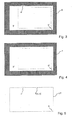
Das Transmissionsbild 3' der Banknote 3 zeigt einen Bereich 4' mit einer gegenüber dem dunklen Hintergrund 6 erhöhten Helligkeit, was darauf zurückzuführen ist, dass das auf die Banknote 3 treffende Licht durch den Klebestreifen 4 in Richtung der Transmissionskamera 23 gestreut und/ oder gebrochen wird und - anders als das an der Transmissionskamera 23 vorbeilaufende Beleuchtungslicht - von der Transmissionskamera 23 erfasst wird. Im Transmissionsbild 3' der Banknote 3 ist ferner ein der Verformung 5 entsprechender Bereich 5' zu erkennen.The transmission image 3 'of the
Im Remissionsbild 3" ist ebenfalls ein der Verformung 5 der Banknote 3 entsprechender Bereich 5" zu erkennen. Anders als im Transmissionsbild 3', an dessen oberem Rand ein der Lage des Klebestreifens 4 entsprechender heller Bereich 4' zu erkennen ist (siehe
Nach der Aufnahme des Transmissionsbildes 3' sowie des Remissionsbildes 3" der Banknote 3 wird sowohl aus dem Transmissionsbild 3'als auch aus dem Remissionsbild 3" der Verlauf des Randes des jeweiligen Bildes 3' bzw. 3" ermittelt, z.B. indem die ersten bzw. zweiten Signalwerte, die Signalwerte im Bereich sowohl des Bildes 3' bzw. 3" als auch des Hintergrunds 6 bzw. 7 enthalten, mit jeweils einem Schwellenwert verglichen werden. Sensorsignale, deren Höhe den vorgegebenen Schwellenwert überschreitet, werden hierbei dem Transmissionsbild 3' bzw. Remissionsbild 3" zugeordnet, während Sensorsignale, die den vorgegebenen Schwellenwert unterschreiten, dem Hintergrund 6 bzw. 7 zugeordnet werden.After recording the transmission image 3 'and the
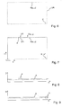
Anschließend wird an der Transmissions- und Remissionsaufnahme eine Kantendetektion durchgeführt, bei welcher jeweils ein aus einer Vielzahl von Randpunkten T(x, y) bzw. R(x, y) zusammengesetzter Verlauf VT bzw. VR des Randes des Transmissionsbildes 3' bzw. Remissionsbildes 3" der Banknote 3 ermittelt wird, welcher beispielhaft in den
Wie bereits im Zusammenhang mit den
In einem weiteren Schritt werden die ersten und zweiten Randpunkte T(x, y) bzw. R(x, y) derart transformiert, insbesondere durch Drehung und/oder Translation, dass die vier Ecken des Randverlaufs VT des Transmissionsbildes 3' mit den vier Ecken des Randverlaufs VR des Remissionsbildes 3" zusammenfallen. Die Koordinaten x und y der Randpunkte T(x, y) und R(x, y) sind dann auf einen gemeinsamen Koordinatenursprung bezogen, welcher vorzugsweise - wie in
Ausgehend von den weitestgehend in Übereinstimmung gebrachten Randverläufen VT und VR wird sodann für ein oder mehrere Paare von Randpunkten T(x, y) des Transmissionsbildes und Randpunkten R(x, y) des Remissionsbildes jeweils ein Abstandswert D berechnet, welcher ein Maß für den Abstand zwischen den ersten Randpunkten T(x, y) von den entsprechenden zweiten Randpunkten R (x, y) darstellt. Beispielsweise wird als Abstandswert D der sogenannte euklidische Abstand zwischen den jeweiligen beiden Punkten T(x, y) und R(x, y) wie folgt berechnet: 
Wobei xT und yT die Koordinaten des ersten Randpunktes T(x, y) und xR und yR die Koordinaten des zweiten Randpunktes R(x, y) darstellen.Where x T and y T represent the coordinates of the first edge point T (x, y) and x R and y R represent the coordinates of the second edge point R (x, y).
Grundsätzlich ist es möglich, einen oder mehrere Abstandswerte D nur in bestimmten Abschnitten der beiden Randverläufe VT bzw. VR zu berechnen. Es ist jedoch bevorzugt, die Abstandswerte D für viele oder alle Paare von ersten und zweiten Randpunkten T(x, y) bzw. R(x, y) entlang der Randverläufe VT und VR zu bestimmen, um etwaige Klebestreifen auf der Banknote mit besonders hoher Zuverlässigkeit erkennen zu können.In principle, it is possible to calculate one or more distance values D only in certain sections of the two edge courses VT or VR. However, it is preferable to determine the distance values D for many or all of the pairs of first and second edge points T (x, y) and R (x, y) along the margins VT and VR, in order to obtain particularly high levels of adhesive tape on the banknote To recognize reliability.
Im Vergleich dazu zeigt
Mit Hilfe des vorstehend beschriebenen Verfahrens bzw. anhand der entsprechenden Vorrichtung kann somit auf einfache und zuverlässige Weise unterschieden werden, ob die mittels Bildsensoren erfassten Abweichungen vom Kantenverlauf der Banknote durch Verformungen, insbesondere Verzerrungen oder Ausbuchtungen, der Banknote selbst oder etwa einen auf der Banknote befindlichen Klebestreifen verursacht werden. Im Ergebnis wird dadurch zuverlässig verhindert, dass eine Banknote, welche lediglich derartige Verformungen, jedoch keine Klebestreifen aufweist, fälschlicherweise aus dem Umlauf genommen und gegebenenfalls einer Vernichtung zugeführt wird.With the aid of the method described above or with the aid of the corresponding device, it can thus be distinguished in a simple and reliable manner whether the deviations from the edge profile of the banknote detected by image sensors are due to deformations, in particular distortions or bulges, of the banknote itself or about one located on the banknote Adhesive strips are caused. As a result, it is reliably prevented that a banknote which has only such deformations but no adhesive strips is incorrectly taken out of circulation and, if necessary, destroyed.
Claims (14)
- An apparatus for checking value documents (3), in particular banknotes, having- at least one sensor (21 - 23) for capturing an electromagnetic radiation transmitted by a value document (3) and generating corresponding first sensor signals (3') that correspond to the electromagnetic radiation respectively transmitted in the region of the edge of the value document (3), and for capturing an electromagnetic radiation remitted by the value document (3) and generating corresponding second sensor signals (3") that correspond to the electromagnetic radiation respectively remitted in the region of the edge of the value document (3), wherein the at least one sensor is configured for generating a transmission image composed of first sensor signals and a remission image of the value document composed of second sensor signals, and- an evaluation device (51) for checking whether the value document (3) has a foreign object (4), in particular adhesive tape, taking into account the first sensor signals (3') and taking into account the second sensor signals (3"), wherein on the basis of possible differences between an edge course of the value document ascertained from the transmission image of the value document and an edge course of the value document ascertained from the remission image of the value document a conclusion is drawn as to the presence of a foreign object.
- The apparatus according to claim 1, wherein the evaluation device (51) is configured such that, upon the check of whether the value document (3) has a foreign object (4), in particular adhesive tape, it compares with each other the first sensor signals (3') that correspond to the electromagnetic radiation respectively transmitted in the region of the edge of the value document (3), and the second sensor signals (3") that correspond to the electromagnetic radiation respectively remitted in the region of the edge of the value document (3).
- The apparatus according to either of the preceding claims, wherein the evaluation device (51) is configured for- ascertaining on the basis of the first sensor signals (3') one or more first edge points (T(x, y)) that correspond to the edge of the value document (3),- ascertaining on the basis of the second sensor signals (3") one or more second edge points (R(x, y)) that correspond to the edge of the value document (3), and- comparing the position of at least one of the first edge points (T(x, y)) with the position of at least one of the second edge points (R(x, y)) in order to ascertain a spatial distance between the respective first and the second edge point and/or an area between the first and the second edge points, wherein the positions of those first and second edge points (T(x, y), R(x, y)) are compared with each other that are mutually corresponding points along the edge of the value document (3), and- checking on the basis of the spatial distance and/or the area whether a foreign object, in particular adhesive tape, is present in the region of the edge of the value document.
- The apparatus according to claim 3, wherein the evaluation device (51) is configured for comparing the spatial distance with at least one pre-specified distance comparison value (A), and/or the area with at least one pre-specified area comparison value (F), and, if the distance exceeds the distance comparison value (A) and/or the area the area comparison value (F), for affirming the presence of a foreign object (4), in particular adhesive tape, and otherwise negating the presence of a foreign object (4), in particular adhesive tape.
- The apparatus according to claim 4, wherein the at least one distance comparison value (A)/area comparison value (F) corresponds to a distance value/area value ascertained on the basis of at least one value document on which no foreign object, in particular no adhesive tape, is located.
- The apparatus according to any of claims 3 to 5, wherein the evaluation device (51) is configured for ascertaining the position of the at least one first/second edge point (T(x, y), R(x, y)) by comparing the first/ second sensor signals (3' and 3") with at least one threshold value.
- The apparatus according to any of claims 3 to 6, wherein the course of the value-document edge is ascertained in transmission from the first sensor signals (3') by means of edge detection and the positions of a multiplicity of first edge points are ascertained therefrom, and wherein the edge course of the value document is ascertained in remission from the second sensor signals (3') by means of edge detection and the positions of a multiplicity of second edge points therefrom.
- The apparatus according to any of claims 3 to 7, wherein the evaluation device (51) is configured for ascertaining a distance value (D) for the spatial distance between the respective first edge point and the respective second edge point that corresponds to the respective first edge point along the edge of the value document (3), said value representing a measure of the spatial distance of the respective first edge point (T(x, y)) from the respective second edge point (R(x, y)).
- The apparatus according to any of claims 3 to 8, wherein the evaluation device (51) is configured for- respectively ascertaining a distance value (D) for a plurality of pairs of a first and a second edge point, and checking whether a pre-specified minimum number (N) of pairs of edge points exceeds the distance comparison value (A), and- if the distance value (D) exceeds the distance comparison value (A) for at least a pre-specified minimum number (N) of pairs of edge points, affirming the presence of a foreign object (4), in particular adhesive tape, and otherwise negating the presence of a foreign object (4), in particular adhesive tape.
- The apparatus according to any of claims 3 to 9, wherein the evaluation device (51) is configured for ascertaining a number (n) of distance values (D) that are greater than the distance comparison value (A), and for carrying out the check of whether the value document (3) has a foreign object (4), in particular adhesive tape, on the basis of a comparison of the ascertained number (n) of distance values (D) that are greater than the distance comparison value (A) with a pre-specified minimum number (N) of distance values.
- The apparatus according to any of claims 8 to 10, wherein the at least one distance value (D) is the Euclidean distance between a first and a second edge point (T(x, y), R(x, y)) in each case.
- The apparatus according to any of the preceding claims, wherein the at least one sensor (21 - 23) is configured for the spatially resolved capture of the electromagnetic radiation transmitted by the value document (3) and the electromagnetic radiation remitted by the value document and for generating corresponding first and second sensor signals (3' and 3").
- A value-document processing system (1) having at least one apparatus (2, 8, 10 - 13, 30, 31, 50) for processing, in particular conveying and/or counting and/or sorting, value documents (3), in particular bank notes, and having an apparatus (21 - 23, 51) for checking value documents (3) according to any of the preceding claims.
- A method for checking value documents (3), in particular banknotes, having the following steps of:- capturing an electromagnetic radiation transmitted by a value document (3) and generating corresponding first sensor signals (3') and a transmission image of the value document composed of first sensor signals,- capturing an electromagnetic radiation remitted by the value document (3) and generating corresponding second sensor signals (3") and a remission image of the value document composed of second sensor signals, and- checking whether the value document (3) has a foreign object (4), in particular adhesive tape, taking into account the first and second sensor signals (3', 3") that correspond to the electromagnetic radiation respectively transmitted or remitted in the region of the edge of the value document (3), wherein on the basis of possible differences between an edge course of the value document ascertained from the transmission image of the value document and an edge course of the value document ascertained from the remission image of the value document a conclusion is drawn as to the presence of a foreign object.
Applications Claiming Priority (2)
| Application Number | Priority Date | Filing Date | Title |
|---|---|---|---|
| DE102013006925.4A DE102013006925A1 (en) | 2013-04-22 | 2013-04-22 | Device and method for checking value documents, in particular banknotes, as well as value document processing system |
| PCT/EP2014/001055 WO2014173522A1 (en) | 2013-04-22 | 2014-04-17 | Device and method for examining value documents, in particular banknotes, and value document processing system |
Publications (2)
| Publication Number | Publication Date |
|---|---|
| EP2997553A1 EP2997553A1 (en) | 2016-03-23 |
| EP2997553B1 true EP2997553B1 (en) | 2018-11-14 |
Family
ID=50543013
Family Applications (1)
| Application Number | Title | Priority Date | Filing Date |
|---|---|---|---|
| EP14718518.5A Active EP2997553B1 (en) | 2013-04-22 | 2014-04-17 | Device and method for examining value documents, in particular banknotes, and value document processing system |
Country Status (7)
| Country | Link |
|---|---|
| US (1) | US9852568B2 (en) |
| EP (1) | EP2997553B1 (en) |
| AU (1) | AU2014256522B2 (en) |
| CA (1) | CA2902244C (en) |
| DE (1) | DE102013006925A1 (en) |
| MX (1) | MX356923B (en) |
| WO (1) | WO2014173522A1 (en) |
Families Citing this family (3)
| Publication number | Priority date | Publication date | Assignee | Title |
|---|---|---|---|---|
| DE102013021655A1 (en) | 2013-12-18 | 2015-06-18 | Giesecke & Devrient Gmbh | Method and device for processing value documents |
| EP3598401B1 (en) * | 2017-03-15 | 2022-01-12 | Glory Ltd. | Paper sheet detection device, paper sheet processing apparatus, and paper sheet detection method |
| US11072507B2 (en) | 2018-04-20 | 2021-07-27 | Crane Payment Innovations, Inc. | Multi-purpose imaging system for active steering system, recognition and string detection system |
Family Cites Families (11)
| Publication number | Priority date | Publication date | Assignee | Title |
|---|---|---|---|---|
| GB2379501A (en) * | 2001-09-06 | 2003-03-12 | Ncr Int Inc | Media detection and validation system with transmission and reflection optical detectors |
| DE10227354A1 (en) * | 2002-06-19 | 2004-01-08 | Giesecke & Devrient Gmbh | Detection of foreign objects on or in banknotes |
| DE102005009332B4 (en) * | 2005-03-01 | 2014-02-13 | Giesecke & Devrient Gmbh | Device for checking the separation of banknotes |
| AT502069B1 (en) * | 2005-06-21 | 2007-07-15 | Arc Seibersdorf Res Gmbh | METHOD AND DEVICE FOR TESTING OBJECTS |
| JP5209982B2 (en) * | 2008-01-31 | 2013-06-12 | 株式会社ユニバーサルエンターテインメント | Paper sheet identification device and paper sheet identification method |
| DE102008051758A1 (en) | 2008-10-15 | 2010-04-22 | Giesecke & Devrient Gmbh | Method and device for processing value documents |
| US8265346B2 (en) * | 2008-11-25 | 2012-09-11 | De La Rue North America Inc. | Determining document fitness using sequenced illumination |
| DE102009032227A1 (en) * | 2009-07-08 | 2011-01-13 | Giesecke & Devrient Gmbh | Procedure for the examination of value documents |
| DE102009048002A1 (en) * | 2009-10-02 | 2011-04-07 | Beb Industrie-Elektronik Ag | Method and device for checking the degree of soiling of banknotes |
| RU2438182C1 (en) * | 2010-04-08 | 2011-12-27 | Общество С Ограниченной Ответственностью "Конструкторское Бюро "Дорс" (Ооо "Кб "Дорс") | Method of processing banknotes (versions) |
| DE102010021803A1 (en) | 2010-05-27 | 2011-12-01 | Giesecke & Devrient Gmbh | Apparatus for checking the authenticity of documents of value |
-
2013
- 2013-04-22 DE DE102013006925.4A patent/DE102013006925A1/en not_active Withdrawn
-
2014
- 2014-04-17 AU AU2014256522A patent/AU2014256522B2/en active Active
- 2014-04-17 CA CA2902244A patent/CA2902244C/en active Active
- 2014-04-17 US US14/784,883 patent/US9852568B2/en active Active
- 2014-04-17 MX MX2015014721A patent/MX356923B/en active IP Right Grant
- 2014-04-17 WO PCT/EP2014/001055 patent/WO2014173522A1/en active Application Filing
- 2014-04-17 EP EP14718518.5A patent/EP2997553B1/en active Active
Non-Patent Citations (1)
| Title |
|---|
| None * |
Also Published As
| Publication number | Publication date |
|---|---|
| MX356923B (en) | 2018-06-20 |
| CA2902244A1 (en) | 2014-10-30 |
| AU2014256522B2 (en) | 2017-11-23 |
| MX2015014721A (en) | 2016-03-07 |
| AU2014256522A1 (en) | 2015-10-15 |
| EP2997553A1 (en) | 2016-03-23 |
| DE102013006925A1 (en) | 2014-10-23 |
| US9852568B2 (en) | 2017-12-26 |
| US20160063791A1 (en) | 2016-03-03 |
| WO2014173522A1 (en) | 2014-10-30 |
| CA2902244C (en) | 2021-03-16 |
Similar Documents
| Publication | Publication Date | Title |
|---|---|---|
| DE2824849C2 (en) | Method and device for determining the condition and / or the authenticity of sheet material | |
| EP2577620B1 (en) | Device for testing the authenticity of valuable documents | |
| EP2143081B1 (en) | Method and device for testing value documents | |
| EP2625673B1 (en) | Method for checking an optical security feature of a valuable document | |
| DE102011117239A1 (en) | Method and device for examining a sheet or card-shaped value document with a security feature having one or more cavities | |
| EP3108461B1 (en) | Method for examining a value document, and means for carrying out the method | |
| EP2997553B1 (en) | Device and method for examining value documents, in particular banknotes, and value document processing system | |
| EP2795591B1 (en) | Method and device for examining a document of value | |
| EP2761604B1 (en) | Method for examining the production quality of an optical security feature of a valuable document | |
| EP3443542B1 (en) | Device and method for checking value documents, in particular banknotes, and value document processing system | |
| EP2936455B1 (en) | Sensor and method for verifying value documents | |
| EP3210195B1 (en) | Device and method for testing valuable documents and system for handling of valuable documents | |
| EP3455830B1 (en) | Apparatus and method for checking the authenticity of a security element | |
| EP2920769B1 (en) | Apparatus and method to evaluate valuable documents | |
| EP3539091B1 (en) | Device and method for classifying value documents, in particular bank notes, and value document processing system | |
| EP1567991B1 (en) | Method and device for verifying valuable documents | |
| EP3134878B1 (en) | Method of checking a value document | |
| EP4186041B1 (en) | Sensor and method for checking value documents, in particular bank notes, and value document processing apparatus | |
| WO2024012634A1 (en) | Sensor and method for checking valuable documents having at least one reflective security element | |
| EP3516634B1 (en) | Method and device for detecting color fading on a banknote, and value-document processing system | |
| WO2024002420A1 (en) | Device and method for testing flat samples | |
| DE10160580A1 (en) | Method for testing banknote validity using ultraviolet light, whereby banknotes are illuminated with both UV and visible light and the ratio of reflected light determined to negate the effects of dirt on the note surfaces | |
| EP3408839A1 (en) | Method and device for checking value documents |
Legal Events
| Date | Code | Title | Description |
|---|---|---|---|
| PUAI | Public reference made under article 153(3) epc to a published international application that has entered the european phase |
Free format text: ORIGINAL CODE: 0009012 |
|
| 17P | Request for examination filed |
Effective date: 20151123 |
|
| AK | Designated contracting states |
Kind code of ref document: A1 Designated state(s): AL AT BE BG CH CY CZ DE DK EE ES FI FR GB GR HR HU IE IS IT LI LT LU LV MC MK MT NL NO PL PT RO RS SE SI SK SM TR |
|
| AX | Request for extension of the european patent |
Extension state: BA ME |
|
| DAX | Request for extension of the european patent (deleted) | ||
| RAP1 | Party data changed (applicant data changed or rights of an application transferred) |
Owner name: GIESECKE+DEVRIENT CURRENCY TECHNOLOGY GMBH |
|
| GRAP | Despatch of communication of intention to grant a patent |
Free format text: ORIGINAL CODE: EPIDOSNIGR1 |
|
| STAA | Information on the status of an ep patent application or granted ep patent |
Free format text: STATUS: GRANT OF PATENT IS INTENDED |
|
| INTG | Intention to grant announced |
Effective date: 20180607 |
|
| GRAJ | Information related to disapproval of communication of intention to grant by the applicant or resumption of examination proceedings by the epo deleted |
Free format text: ORIGINAL CODE: EPIDOSDIGR1 |
|
| STAA | Information on the status of an ep patent application or granted ep patent |
Free format text: STATUS: REQUEST FOR EXAMINATION WAS MADE |
|
| GRAP | Despatch of communication of intention to grant a patent |
Free format text: ORIGINAL CODE: EPIDOSNIGR1 |
|
| STAA | Information on the status of an ep patent application or granted ep patent |
Free format text: STATUS: GRANT OF PATENT IS INTENDED |
|
| INTC | Intention to grant announced (deleted) | ||
| INTG | Intention to grant announced |
Effective date: 20180801 |
|
| GRAS | Grant fee paid |
Free format text: ORIGINAL CODE: EPIDOSNIGR3 |
|
| GRAA | (expected) grant |
Free format text: ORIGINAL CODE: 0009210 |
|
| STAA | Information on the status of an ep patent application or granted ep patent |
Free format text: STATUS: THE PATENT HAS BEEN GRANTED |
|
| AK | Designated contracting states |
Kind code of ref document: B1 Designated state(s): AL AT BE BG CH CY CZ DE DK EE ES FI FR GB GR HR HU IE IS IT LI LT LU LV MC MK MT NL NO PL PT RO RS SE SI SK SM TR |
|
| REG | Reference to a national code |
Ref country code: CH Ref legal event code: EP Ref country code: AT Ref legal event code: REF Ref document number: 1065761 Country of ref document: AT Kind code of ref document: T Effective date: 20181115 |
|
| REG | Reference to a national code |
Ref country code: DE Ref legal event code: R096 Ref document number: 502014010064 Country of ref document: DE |
|
| REG | Reference to a national code |
Ref country code: IE Ref legal event code: FG4D Free format text: LANGUAGE OF EP DOCUMENT: GERMAN |
|
| REG | Reference to a national code |
Ref country code: NL Ref legal event code: MP Effective date: 20181114 |
|
| REG | Reference to a national code |
Ref country code: LT Ref legal event code: MG4D |
|
| PG25 | Lapsed in a contracting state [announced via postgrant information from national office to epo] |
Ref country code: LV Free format text: LAPSE BECAUSE OF FAILURE TO SUBMIT A TRANSLATION OF THE DESCRIPTION OR TO PAY THE FEE WITHIN THE PRESCRIBED TIME-LIMIT Effective date: 20181114 Ref country code: HR Free format text: LAPSE BECAUSE OF FAILURE TO SUBMIT A TRANSLATION OF THE DESCRIPTION OR TO PAY THE FEE WITHIN THE PRESCRIBED TIME-LIMIT Effective date: 20181114 Ref country code: NO Free format text: LAPSE BECAUSE OF FAILURE TO SUBMIT A TRANSLATION OF THE DESCRIPTION OR TO PAY THE FEE WITHIN THE PRESCRIBED TIME-LIMIT Effective date: 20190214 Ref country code: FI Free format text: LAPSE BECAUSE OF FAILURE TO SUBMIT A TRANSLATION OF THE DESCRIPTION OR TO PAY THE FEE WITHIN THE PRESCRIBED TIME-LIMIT Effective date: 20181114 Ref country code: BG Free format text: LAPSE BECAUSE OF FAILURE TO SUBMIT A TRANSLATION OF THE DESCRIPTION OR TO PAY THE FEE WITHIN THE PRESCRIBED TIME-LIMIT Effective date: 20190214 Ref country code: IS Free format text: LAPSE BECAUSE OF FAILURE TO SUBMIT A TRANSLATION OF THE DESCRIPTION OR TO PAY THE FEE WITHIN THE PRESCRIBED TIME-LIMIT Effective date: 20190314 Ref country code: LT Free format text: LAPSE BECAUSE OF FAILURE TO SUBMIT A TRANSLATION OF THE DESCRIPTION OR TO PAY THE FEE WITHIN THE PRESCRIBED TIME-LIMIT Effective date: 20181114 Ref country code: ES Free format text: LAPSE BECAUSE OF FAILURE TO SUBMIT A TRANSLATION OF THE DESCRIPTION OR TO PAY THE FEE WITHIN THE PRESCRIBED TIME-LIMIT Effective date: 20181114 |
|
| PG25 | Lapsed in a contracting state [announced via postgrant information from national office to epo] |
Ref country code: GR Free format text: LAPSE BECAUSE OF FAILURE TO SUBMIT A TRANSLATION OF THE DESCRIPTION OR TO PAY THE FEE WITHIN THE PRESCRIBED TIME-LIMIT Effective date: 20190215 Ref country code: NL Free format text: LAPSE BECAUSE OF FAILURE TO SUBMIT A TRANSLATION OF THE DESCRIPTION OR TO PAY THE FEE WITHIN THE PRESCRIBED TIME-LIMIT Effective date: 20181114 Ref country code: AL Free format text: LAPSE BECAUSE OF FAILURE TO SUBMIT A TRANSLATION OF THE DESCRIPTION OR TO PAY THE FEE WITHIN THE PRESCRIBED TIME-LIMIT Effective date: 20181114 Ref country code: PT Free format text: LAPSE BECAUSE OF FAILURE TO SUBMIT A TRANSLATION OF THE DESCRIPTION OR TO PAY THE FEE WITHIN THE PRESCRIBED TIME-LIMIT Effective date: 20190314 Ref country code: SE Free format text: LAPSE BECAUSE OF FAILURE TO SUBMIT A TRANSLATION OF THE DESCRIPTION OR TO PAY THE FEE WITHIN THE PRESCRIBED TIME-LIMIT Effective date: 20181114 Ref country code: RS Free format text: LAPSE BECAUSE OF FAILURE TO SUBMIT A TRANSLATION OF THE DESCRIPTION OR TO PAY THE FEE WITHIN THE PRESCRIBED TIME-LIMIT Effective date: 20181114 |
|
| PG25 | Lapsed in a contracting state [announced via postgrant information from national office to epo] |
Ref country code: DK Free format text: LAPSE BECAUSE OF FAILURE TO SUBMIT A TRANSLATION OF THE DESCRIPTION OR TO PAY THE FEE WITHIN THE PRESCRIBED TIME-LIMIT Effective date: 20181114 Ref country code: PL Free format text: LAPSE BECAUSE OF FAILURE TO SUBMIT A TRANSLATION OF THE DESCRIPTION OR TO PAY THE FEE WITHIN THE PRESCRIBED TIME-LIMIT Effective date: 20181114 Ref country code: CZ Free format text: LAPSE BECAUSE OF FAILURE TO SUBMIT A TRANSLATION OF THE DESCRIPTION OR TO PAY THE FEE WITHIN THE PRESCRIBED TIME-LIMIT Effective date: 20181114 Ref country code: IT Free format text: LAPSE BECAUSE OF FAILURE TO SUBMIT A TRANSLATION OF THE DESCRIPTION OR TO PAY THE FEE WITHIN THE PRESCRIBED TIME-LIMIT Effective date: 20181114 |
|
| REG | Reference to a national code |
Ref country code: DE Ref legal event code: R097 Ref document number: 502014010064 Country of ref document: DE |
|
| PG25 | Lapsed in a contracting state [announced via postgrant information from national office to epo] |
Ref country code: RO Free format text: LAPSE BECAUSE OF FAILURE TO SUBMIT A TRANSLATION OF THE DESCRIPTION OR TO PAY THE FEE WITHIN THE PRESCRIBED TIME-LIMIT Effective date: 20181114 Ref country code: SK Free format text: LAPSE BECAUSE OF FAILURE TO SUBMIT A TRANSLATION OF THE DESCRIPTION OR TO PAY THE FEE WITHIN THE PRESCRIBED TIME-LIMIT Effective date: 20181114 Ref country code: SM Free format text: LAPSE BECAUSE OF FAILURE TO SUBMIT A TRANSLATION OF THE DESCRIPTION OR TO PAY THE FEE WITHIN THE PRESCRIBED TIME-LIMIT Effective date: 20181114 Ref country code: EE Free format text: LAPSE BECAUSE OF FAILURE TO SUBMIT A TRANSLATION OF THE DESCRIPTION OR TO PAY THE FEE WITHIN THE PRESCRIBED TIME-LIMIT Effective date: 20181114 |
|
| PLBE | No opposition filed within time limit |
Free format text: ORIGINAL CODE: 0009261 |
|
| STAA | Information on the status of an ep patent application or granted ep patent |
Free format text: STATUS: NO OPPOSITION FILED WITHIN TIME LIMIT |
|
| 26N | No opposition filed |
Effective date: 20190815 |
|
| PG25 | Lapsed in a contracting state [announced via postgrant information from national office to epo] |
Ref country code: SI Free format text: LAPSE BECAUSE OF FAILURE TO SUBMIT A TRANSLATION OF THE DESCRIPTION OR TO PAY THE FEE WITHIN THE PRESCRIBED TIME-LIMIT Effective date: 20181114 |
|
| REG | Reference to a national code |
Ref country code: CH Ref legal event code: PL |
|
| REG | Reference to a national code |
Ref country code: BE Ref legal event code: MM Effective date: 20190430 |
|
| PG25 | Lapsed in a contracting state [announced via postgrant information from national office to epo] |
Ref country code: MC Free format text: LAPSE BECAUSE OF FAILURE TO SUBMIT A TRANSLATION OF THE DESCRIPTION OR TO PAY THE FEE WITHIN THE PRESCRIBED TIME-LIMIT Effective date: 20181114 Ref country code: LU Free format text: LAPSE BECAUSE OF NON-PAYMENT OF DUE FEES Effective date: 20190417 |
|
| PG25 | Lapsed in a contracting state [announced via postgrant information from national office to epo] |
Ref country code: CH Free format text: LAPSE BECAUSE OF NON-PAYMENT OF DUE FEES Effective date: 20190430 Ref country code: LI Free format text: LAPSE BECAUSE OF NON-PAYMENT OF DUE FEES Effective date: 20190430 |
|
| PG25 | Lapsed in a contracting state [announced via postgrant information from national office to epo] |
Ref country code: FR Free format text: LAPSE BECAUSE OF NON-PAYMENT OF DUE FEES Effective date: 20190430 Ref country code: BE Free format text: LAPSE BECAUSE OF NON-PAYMENT OF DUE FEES Effective date: 20190430 |
|
| PG25 | Lapsed in a contracting state [announced via postgrant information from national office to epo] |
Ref country code: TR Free format text: LAPSE BECAUSE OF FAILURE TO SUBMIT A TRANSLATION OF THE DESCRIPTION OR TO PAY THE FEE WITHIN THE PRESCRIBED TIME-LIMIT Effective date: 20181114 |
|
| PG25 | Lapsed in a contracting state [announced via postgrant information from national office to epo] |
Ref country code: IE Free format text: LAPSE BECAUSE OF NON-PAYMENT OF DUE FEES Effective date: 20190417 |
|
| REG | Reference to a national code |
Ref country code: AT Ref legal event code: MM01 Ref document number: 1065761 Country of ref document: AT Kind code of ref document: T Effective date: 20190417 |
|
| PG25 | Lapsed in a contracting state [announced via postgrant information from national office to epo] |
Ref country code: AT Free format text: LAPSE BECAUSE OF NON-PAYMENT OF DUE FEES Effective date: 20190417 |
|
| PG25 | Lapsed in a contracting state [announced via postgrant information from national office to epo] |
Ref country code: CY Free format text: LAPSE BECAUSE OF FAILURE TO SUBMIT A TRANSLATION OF THE DESCRIPTION OR TO PAY THE FEE WITHIN THE PRESCRIBED TIME-LIMIT Effective date: 20181114 |
|
| PG25 | Lapsed in a contracting state [announced via postgrant information from national office to epo] |
Ref country code: MT Free format text: LAPSE BECAUSE OF FAILURE TO SUBMIT A TRANSLATION OF THE DESCRIPTION OR TO PAY THE FEE WITHIN THE PRESCRIBED TIME-LIMIT Effective date: 20181114 Ref country code: HU Free format text: LAPSE BECAUSE OF FAILURE TO SUBMIT A TRANSLATION OF THE DESCRIPTION OR TO PAY THE FEE WITHIN THE PRESCRIBED TIME-LIMIT; INVALID AB INITIO Effective date: 20140417 |
|
| PG25 | Lapsed in a contracting state [announced via postgrant information from national office to epo] |
Ref country code: MK Free format text: LAPSE BECAUSE OF FAILURE TO SUBMIT A TRANSLATION OF THE DESCRIPTION OR TO PAY THE FEE WITHIN THE PRESCRIBED TIME-LIMIT Effective date: 20181114 |
|
| REG | Reference to a national code |
Ref country code: DE Ref legal event code: R084 Ref document number: 502014010064 Country of ref document: DE |
|
| P01 | Opt-out of the competence of the unified patent court (upc) registered |
Effective date: 20230520 |
|
| PGFP | Annual fee paid to national office [announced via postgrant information from national office to epo] |
Ref country code: DE Payment date: 20230430 Year of fee payment: 10 |
|
| PGFP | Annual fee paid to national office [announced via postgrant information from national office to epo] |
Ref country code: GB Payment date: 20230420 Year of fee payment: 10 |