EP2968857B1 - Shape sensor systems for tracking interventional instruments - Google Patents
Shape sensor systems for tracking interventional instruments Download PDFInfo
- Publication number
- EP2968857B1 EP2968857B1 EP14769738.7A EP14769738A EP2968857B1 EP 2968857 B1 EP2968857 B1 EP 2968857B1 EP 14769738 A EP14769738 A EP 14769738A EP 2968857 B1 EP2968857 B1 EP 2968857B1
- Authority
- EP
- European Patent Office
- Prior art keywords
- sensor
- shape
- tracking system
- shape sensor
- fiber
- Prior art date
- Legal status (The legal status is an assumption and is not a legal conclusion. Google has not performed a legal analysis and makes no representation as to the accuracy of the status listed.)
- Active
Links
- 239000013307 optical fiber Substances 0.000 claims description 29
- 210000003484 anatomy Anatomy 0.000 claims description 23
- 238000003032 molecular docking Methods 0.000 claims description 17
- 230000013011 mating Effects 0.000 claims description 14
- 239000003550 marker Substances 0.000 claims description 9
- 238000004804 winding Methods 0.000 claims description 6
- 230000000717 retained effect Effects 0.000 claims description 4
- 238000003780 insertion Methods 0.000 claims description 3
- 230000037431 insertion Effects 0.000 claims description 3
- 239000000835 fiber Substances 0.000 description 102
- 238000000034 method Methods 0.000 description 44
- 238000003384 imaging method Methods 0.000 description 22
- 238000012545 processing Methods 0.000 description 15
- 230000033001 locomotion Effects 0.000 description 11
- 238000005516 engineering process Methods 0.000 description 10
- 230000003287 optical effect Effects 0.000 description 9
- 238000005452 bending Methods 0.000 description 7
- 239000000853 adhesive Substances 0.000 description 6
- 230000001070 adhesive effect Effects 0.000 description 6
- 238000002594 fluoroscopy Methods 0.000 description 6
- 230000008569 process Effects 0.000 description 6
- 238000001574 biopsy Methods 0.000 description 5
- 238000013152 interventional procedure Methods 0.000 description 5
- 230000007246 mechanism Effects 0.000 description 5
- 239000012636 effector Substances 0.000 description 4
- 230000000977 initiatory effect Effects 0.000 description 4
- 210000004072 lung Anatomy 0.000 description 4
- 238000012014 optical coherence tomography Methods 0.000 description 4
- 238000003860 storage Methods 0.000 description 4
- 239000000126 substance Substances 0.000 description 4
- 238000001931 thermography Methods 0.000 description 4
- 238000011282 treatment Methods 0.000 description 4
- 210000001072 colon Anatomy 0.000 description 3
- 230000006870 function Effects 0.000 description 3
- 210000000936 intestine Anatomy 0.000 description 3
- 210000003734 kidney Anatomy 0.000 description 3
- 239000000523 sample Substances 0.000 description 3
- 239000004065 semiconductor Substances 0.000 description 3
- 230000001225 therapeutic effect Effects 0.000 description 3
- 230000000712 assembly Effects 0.000 description 2
- 238000000429 assembly Methods 0.000 description 2
- 230000008901 benefit Effects 0.000 description 2
- 210000004556 brain Anatomy 0.000 description 2
- 230000008859 change Effects 0.000 description 2
- 238000005253 cladding Methods 0.000 description 2
- 238000004891 communication Methods 0.000 description 2
- 238000013461 design Methods 0.000 description 2
- 230000005672 electromagnetic field Effects 0.000 description 2
- 238000002595 magnetic resonance imaging Methods 0.000 description 2
- 238000005259 measurement Methods 0.000 description 2
- 238000012544 monitoring process Methods 0.000 description 2
- 239000002071 nanotube Substances 0.000 description 2
- 230000036961 partial effect Effects 0.000 description 2
- 238000001454 recorded image Methods 0.000 description 2
- 230000004044 response Effects 0.000 description 2
- 238000002432 robotic surgery Methods 0.000 description 2
- 230000005477 standard model Effects 0.000 description 2
- 230000003068 static effect Effects 0.000 description 2
- 238000001356 surgical procedure Methods 0.000 description 2
- 238000003325 tomography Methods 0.000 description 2
- 238000002604 ultrasonography Methods 0.000 description 2
- 238000001069 Raman spectroscopy Methods 0.000 description 1
- 208000002847 Surgical Wound Diseases 0.000 description 1
- 230000001133 acceleration Effects 0.000 description 1
- 239000012620 biological material Substances 0.000 description 1
- 230000005540 biological transmission Effects 0.000 description 1
- 230000001010 compromised effect Effects 0.000 description 1
- 238000010276 construction Methods 0.000 description 1
- 230000002939 deleterious effect Effects 0.000 description 1
- 238000001514 detection method Methods 0.000 description 1
- 238000003745 diagnosis Methods 0.000 description 1
- 230000000694 effects Effects 0.000 description 1
- 238000001839 endoscopy Methods 0.000 description 1
- 238000005286 illumination Methods 0.000 description 1
- 238000002675 image-guided surgery Methods 0.000 description 1
- 239000007943 implant Substances 0.000 description 1
- 238000002329 infrared spectrum Methods 0.000 description 1
- 230000002262 irrigation Effects 0.000 description 1
- 238000003973 irrigation Methods 0.000 description 1
- 238000000608 laser ablation Methods 0.000 description 1
- 230000004807 localization Effects 0.000 description 1
- 238000004519 manufacturing process Methods 0.000 description 1
- 239000002184 metal Substances 0.000 description 1
- 238000002324 minimally invasive surgery Methods 0.000 description 1
- 238000012986 modification Methods 0.000 description 1
- 230000004048 modification Effects 0.000 description 1
- 210000000056 organ Anatomy 0.000 description 1
- 230000008447 perception Effects 0.000 description 1
- 238000011084 recovery Methods 0.000 description 1
- 230000002829 reductive effect Effects 0.000 description 1
- 230000029058 respiratory gaseous exchange Effects 0.000 description 1
- 230000026676 system process Effects 0.000 description 1
- 238000002211 ultraviolet spectrum Methods 0.000 description 1
- 238000001429 visible spectrum Methods 0.000 description 1
- 238000012800 visualization Methods 0.000 description 1
Images


Classifications
-
- A—HUMAN NECESSITIES
- A61—MEDICAL OR VETERINARY SCIENCE; HYGIENE
- A61B—DIAGNOSIS; SURGERY; IDENTIFICATION
- A61B5/00—Measuring for diagnostic purposes; Identification of persons
- A61B5/06—Devices, other than using radiation, for detecting or locating foreign bodies ; determining position of probes within or on the body of the patient
- A61B5/061—Determining position of a probe within the body employing means separate from the probe, e.g. sensing internal probe position employing impedance electrodes on the surface of the body
- A61B5/064—Determining position of a probe within the body employing means separate from the probe, e.g. sensing internal probe position employing impedance electrodes on the surface of the body using markers
-
- A—HUMAN NECESSITIES
- A61—MEDICAL OR VETERINARY SCIENCE; HYGIENE
- A61B—DIAGNOSIS; SURGERY; IDENTIFICATION
- A61B34/00—Computer-aided surgery; Manipulators or robots specially adapted for use in surgery
- A61B34/20—Surgical navigation systems; Devices for tracking or guiding surgical instruments, e.g. for frameless stereotaxis
-
- A—HUMAN NECESSITIES
- A61—MEDICAL OR VETERINARY SCIENCE; HYGIENE
- A61B—DIAGNOSIS; SURGERY; IDENTIFICATION
- A61B34/00—Computer-aided surgery; Manipulators or robots specially adapted for use in surgery
- A61B34/30—Surgical robots
-
- A—HUMAN NECESSITIES
- A61—MEDICAL OR VETERINARY SCIENCE; HYGIENE
- A61B—DIAGNOSIS; SURGERY; IDENTIFICATION
- A61B34/00—Computer-aided surgery; Manipulators or robots specially adapted for use in surgery
- A61B34/10—Computer-aided planning, simulation or modelling of surgical operations
- A61B2034/101—Computer-aided simulation of surgical operations
- A61B2034/105—Modelling of the patient, e.g. for ligaments or bones
-
- A—HUMAN NECESSITIES
- A61—MEDICAL OR VETERINARY SCIENCE; HYGIENE
- A61B—DIAGNOSIS; SURGERY; IDENTIFICATION
- A61B34/00—Computer-aided surgery; Manipulators or robots specially adapted for use in surgery
- A61B34/20—Surgical navigation systems; Devices for tracking or guiding surgical instruments, e.g. for frameless stereotaxis
- A61B2034/2046—Tracking techniques
- A61B2034/2061—Tracking techniques using shape-sensors, e.g. fiber shape sensors with Bragg gratings
-
- A—HUMAN NECESSITIES
- A61—MEDICAL OR VETERINARY SCIENCE; HYGIENE
- A61B—DIAGNOSIS; SURGERY; IDENTIFICATION
- A61B34/00—Computer-aided surgery; Manipulators or robots specially adapted for use in surgery
- A61B34/30—Surgical robots
- A61B2034/301—Surgical robots for introducing or steering flexible instruments inserted into the body, e.g. catheters or endoscopes
-
- A—HUMAN NECESSITIES
- A61—MEDICAL OR VETERINARY SCIENCE; HYGIENE
- A61B—DIAGNOSIS; SURGERY; IDENTIFICATION
- A61B34/00—Computer-aided surgery; Manipulators or robots specially adapted for use in surgery
- A61B34/30—Surgical robots
- A61B2034/303—Surgical robots specifically adapted for manipulations within body lumens, e.g. within lumen of gut, spine, or blood vessels
-
- A—HUMAN NECESSITIES
- A61—MEDICAL OR VETERINARY SCIENCE; HYGIENE
- A61B—DIAGNOSIS; SURGERY; IDENTIFICATION
- A61B90/00—Instruments, implements or accessories specially adapted for surgery or diagnosis and not covered by any of the groups A61B1/00 - A61B50/00, e.g. for luxation treatment or for protecting wound edges
- A61B90/36—Image-producing devices or illumination devices not otherwise provided for
- A61B2090/363—Use of fiducial points
-
- A—HUMAN NECESSITIES
- A61—MEDICAL OR VETERINARY SCIENCE; HYGIENE
- A61B—DIAGNOSIS; SURGERY; IDENTIFICATION
- A61B90/00—Instruments, implements or accessories specially adapted for surgery or diagnosis and not covered by any of the groups A61B1/00 - A61B50/00, e.g. for luxation treatment or for protecting wound edges
- A61B90/39—Markers, e.g. radio-opaque or breast lesions markers
- A61B2090/3937—Visible markers
-
- A—HUMAN NECESSITIES
- A61—MEDICAL OR VETERINARY SCIENCE; HYGIENE
- A61B—DIAGNOSIS; SURGERY; IDENTIFICATION
- A61B90/00—Instruments, implements or accessories specially adapted for surgery or diagnosis and not covered by any of the groups A61B1/00 - A61B50/00, e.g. for luxation treatment or for protecting wound edges
- A61B90/39—Markers, e.g. radio-opaque or breast lesions markers
- A61B2090/3966—Radiopaque markers visible in an X-ray image
-
- A—HUMAN NECESSITIES
- A61—MEDICAL OR VETERINARY SCIENCE; HYGIENE
- A61B—DIAGNOSIS; SURGERY; IDENTIFICATION
- A61B2560/00—Constructional details of operational features of apparatus; Accessories for medical measuring apparatus
- A61B2560/04—Constructional details of apparatus
- A61B2560/0456—Apparatus provided with a docking unit
-
- A—HUMAN NECESSITIES
- A61—MEDICAL OR VETERINARY SCIENCE; HYGIENE
- A61B—DIAGNOSIS; SURGERY; IDENTIFICATION
- A61B5/00—Measuring for diagnostic purposes; Identification of persons
- A61B5/68—Arrangements of detecting, measuring or recording means, e.g. sensors, in relation to patient
- A61B5/6846—Arrangements of detecting, measuring or recording means, e.g. sensors, in relation to patient specially adapted to be brought in contact with an internal body part, i.e. invasive
- A61B5/6879—Means for maintaining contact with the body
Definitions
- the present disclosure is directed to systems and methods for navigating a patient anatomy to conduct a minimally invasive procedure, and more particularly to systems and methods using shape sensor systems to track interventional instruments.
- Minimally invasive medical techniques are intended to reduce the amount of tissue that is damaged during interventional procedures, thereby reducing patient recovery time, discomfort, and deleterious side effects.
- Such minimally invasive techniques may be performed through natural orifices in a patient anatomy or through one or more surgical incisions. Through these natural orifices or incisions clinicians may insert interventional instruments (including surgical, diagnostic, therapeutic, or biopsy instruments) to reach a target tissue location.
- interventional instruments including surgical, diagnostic, therapeutic, or biopsy instruments
- a minimally invasive interventional instrument may navigate natural or surgically created passageways in anatomical systems such as the lungs, the colon, the intestines, the kidneys, the heart, the circulatory system, or the like.
- EM navigation may be used to track the movement of interventional instruments through a patient anatomy.
- EM navigation systems are useful for many procedures, they may be subject to magnetic interference from other equipment in the surgical suite.
- a C-arm of a fluoroscopic imaging system or metal instruments may generate magnetic interference with EM navigation systems, causing unacceptable errors in the tracking of an interventional instrument.
- Improved navigation systems and methods are needed for tracking interventional instruments in surgical environments, including in environments where EM navigation is not suitable or may be compromised.
- EP 2 436 333 A1 discloses a surgical navigation system including a camera that is fixedly attached to a patient.
- the camera space merges with the patient space and thereby eliminates the need for a separate patient tracker.
- the surgical navigation system calculates the position of a surgical tool with a tracking device in view of the camera and shows on a display device the position of the surgical tool with respect to the patient superimposed and in correlation with a scan image of the patient.
- US 2002/0058864 A1 relates to devices and methods that improve the quality of optic measurements from surfaces such as skin and biological materials.
- US 2009/137952 A1 discloses Robotic medical instrument systems and associated methods utilizing an optical fiber sensors such as Bragg sensor optical fibers.
- an optical fiber is coupled to an elongate instrument body and includes a fiber core having one or more Bragg gratings.
- a controller is configured to initiate various actions in response thereto. For example, a controller may generate and display a graphical representation of the instrument body and depict one or more position and/or orientation variables thereof, or adjust motors of an instrument driver to reposition the catheter or another instrument.
- Optical fibers having Bragg gratings may also be utilized with other system components including a plurality of working instruments that are positioned within a sheath lumen, an instrument driver, localization sensors, and/or an image capture device, and may also be coupled to a patient's body or associated structure that stabilizes the body.
- a medical tracking system comprises a fiducial apparatus that includes a sensor docking feature configured to mate with a mating portion of a sensor device.
- the sensor docking feature retains the mating portion in a known configuration.
- the fiducial apparatus also includes at least one imageable fiducial marker and a surface configured for attachment to an anatomy of a patient.
- a method for medical instrument tracking comprises receiving a model of an anatomic structure.
- the model defines an image reference frame and includes an image of at least one fiducial marker.
- the method further includes registering a reference portion of a first shape sensor device to the plurality of fiducial markers when a fiducial apparatus, including the at least one fiducial marker, is coupled to the first shape sensor device.
- the reference portion of the first shape sensor device is retained in a known configuration relative to the at least one fiducial marker.
- the method further comprises receiving first shape sensor information in a first sensor reference frame from a first shape sensor of the first shape sensor device and determining a pose of the first shape sensor in the image reference frame based on a correlation between the image reference frame and the first sensor reference frame.
- a method for medical instrument tracking comprises receiving a model of an anatomic structure.
- the model defining an image reference frame and including a model of at least one fiducial marker.
- the method further includes receiving first shape sensor information in a first reference frame from a first shape sensor including a reference portion held in a known configuration with respect to the at least one fiducial marker.
- the method further includes receiving second shape sensor information in a second reference frame from a second shape sensor positioned within the anatomic structure.
- the method further includes determining a pose of the second shape sensor in the image reference frame based on a correlation between the first reference frame, the second reference frame, and the image reference frame.
- position refers to the location of an object or a portion of an object in a three-dimensional space (e.g., three degrees of translational freedom along Cartesian X, Y, Z coordinates).
- orientation refers to the rotational placement of an object or a portion of an object (three degrees of rotational freedom - e.g., roll, pitch, and yaw).
- the term “pose” refers to the position of an object or a portion of an object in at least one degree of translational freedom and to the orientation of that object or portion of the object in at least one degree of rotational freedom (up to six total degrees of freedom).
- the term “shape” refers to a set of poses, positions, or orientations measured along an elongated object.
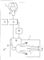
- a robotic interventional system for use in, for example, surgical, diagnostic, therapeutic, or biopsy procedures, is generally indicated by the reference numeral 100.
- the robotic interventional system 100 generally includes a robotic assembly 102 mounted to or near an operating table O on which a patient P is positioned.
- An interventional instrument system 104 is operably coupled to the robotic assembly 102.
- An operator input system 106 allows a surgeon or clinician S to view the surgical site and to control the operation of the interventional instrument system 104.
- the operator input system 106 may be located at a clinician's console which is usually located in the same room as operating table O. However, it should be understood that the surgeon or clinician S can be located in a different room or a completely different building from the patient P.
- Operator input system 106 generally includes one or more control device(s) for controlling the interventional instrument system 104.
- the control device(s) may include any number of a variety of input devices, such as hand grips, joysticks, trackballs, data gloves, trigger-guns, hand-operated controllers, voice recognition devices, touch screens, body motion or presence sensors, or the like.
- control device(s) will be provided with the same degrees of freedom as the interventional instruments of the robotic assembly to provide the clinician with telepresence, or the perception that the control device(s) are integral with the instruments so that the clinician has a strong sense of directly controlling instruments.
- the control device(s) may have more or fewer degrees of freedom than the associated interventional instruments and still provide the clinician with telepresence.
- the control device(s) are manual input devices which move with six degrees of freedom, and which may also include an actuatable handle for actuating instruments (for example, for closing grasping jaws, applying an electrical potential to an electrode, delivering a medicinal treatment, or the like).
- the robotic assembly 102 supports the interventional instrument system 104 and may comprise a kinematic structure of one or more non-servo controlled links (e.g., one or more links that may be manually positioned and locked in place, generally referred to as a set-up structure) and a robotic manipulator.
- the robotic assembly 102 includes plurality of actuators (e.g., motors) that drive inputs on the interventional instrument 104. These motors actively move in response to commands from the control system (e.g., control system 112).
- the motors include drive systems which when coupled to the interventional instrument 104 may advance the interventional instrument into a naturally or surgically created anatomical orifice and/or may move the distal end of the interventional instrument in multiple degrees of freedom, which may include three degrees of linear motion (e.g., linear motion along the X, Y, Z Cartesian axes) and three degrees of rotational motion (e.g., rotation about the X, Y, Z Cartesian axes). Additionally, the motors can be used to actuate an articulable end effector of the instrument for grasping tissue in the jaws of a biopsy device or the like.
- three degrees of linear motion e.g., linear motion along the X, Y, Z Cartesian axes
- rotational motion e.g., rotation about the X, Y, Z Cartesian axes
- the robotic interventional system 100 also includes a sensor system 108 with one or more sub-systems for receiving information about the instruments of the robotic assembly.
- Such sub-systems may include a position sensor system (e.g., an electromagnetic (EM) sensor system); a shape sensor system for determining the position, orientation, speed, pose, and/or shape of the catheter tip and/or of one or more segments along a flexible body of instrument 104; and/or a visualization system for capturing images from the distal end of the catheter system.
- EM electromagnetic
- the robotic interventional system 100 also includes a display system 110 for displaying an image of the surgical site and interventional instruments 104 generated by sub-systems of the sensor system 108.
- the display 110 and the operator input system 106 may be oriented so the operator can control the interventional instrument system 104 and the operator input system 106 as if viewing the workspace in substantially true presence.
- True presence means that the displayed tissue image appears to an operator as if the operator was physically present at the image location and directly viewing the tissue from the perspective of the image.
- display system 110 may present images of the surgical site recorded and/or modeled preoperatively using imaging technology such as computerized tomography (CT), magnetic resonance imaging (MRI), fluoroscopy, thermography, ultrasound, optical coherence tomography (OCT), thermal imaging, impedance imaging, laser imaging, nanotube X-ray imaging, or the like.
- imaging technology such as computerized tomography (CT), magnetic resonance imaging (MRI), fluoroscopy, thermography, ultrasound, optical coherence tomography (OCT), thermal imaging, impedance imaging, laser imaging, nanotube X-ray imaging, or the like.
- CT computerized tomography
- MRI magnetic resonance imaging
- fluoroscopy fluoroscopy
- thermography thermography
- ultrasound ultrasound
- OCT optical coherence tomography
- thermal imaging impedance imaging
- laser imaging laser imaging
- nanotube X-ray imaging or the like.
- the presented preoperative images may include two-dimensional, three-dimensional, or four-dimensional (including e.g., time based or velocity
- the display system 110 may display a virtual visualization image in which the actual location of the interventional instrument is registered (e.g., dynamically referenced) with preoperative or concurrent images to present the clinician with a virtual image of the internal surgical site at the location of the tip of the surgical instrument.
- a virtual visualization image in which the actual location of the interventional instrument is registered (e.g., dynamically referenced) with preoperative or concurrent images to present the clinician with a virtual image of the internal surgical site at the location of the tip of the surgical instrument.
- the display system 110 may display a virtual visualization image in which the actual location of the interventional instrument is registered with prior images (including preoperatively recorded images) or concurrent images to present the clinician with a virtual image of an interventional instrument at the surgical site.
- An image of a portion of the interventional instrument 104 may be superimposed on the virtual image to assist the clinician controlling the interventional instrument.
- the robotic interventional system 100 also includes a control system 112.
- the control system 112 includes at least one processor (not shown), and typically a plurality of processors, for effecting control between the interventional instrument system 104, the operator input system 106, the sensor system 108, and the display system 110.
- the control system 112 also includes programmed instructions (e.g., a computer-readable medium storing the instructions) to implement some or all of the methods described herein. While control system 112 is shown as a single block in the simplified schematic of Fig. 1 , the system may comprise a number of data processing circuits with a portion of the processing optionally being performed on or adjacent the robotic assembly 102, a portion being performed at the operator input system 106, and the like.
- control system 112 supports wireless communication protocols such as Bluetooth, IrDA, HomeRF, IEEE 802.11, DECT, and Wireless Telemetry.
- control system 112 may include one or more servo controllers to provide force and torque feedback from the interventional instrument system 104 to one or more corresponding servomotors for the operator input system 106.
- the servo controller(s) may also transmit signals instructing robotic assembly 102 to move the interventional instruments 104 which extend into an internal surgical site within the patient body via openings in the body. Any suitable conventional or specialized servo controller may be used.
- a servo controller may be separate from, or integrated with, robotic assembly 102.
- the servo controller and robotic assembly are provided as part of a robotic arm cart positioned adjacent to the patient's body.
- the control system 112 may further include a virtual visualization system to provide navigation assistance to the interventional instruments 104.
- Virtual navigation using the virtual visualization system is based upon reference to an acquired dataset associated with the three dimensional structure of the anatomical passageways. More specifically, the virtual visualization system processes images of the surgical site recorded and/or modeled using imaging technology such as computerized tomography (CT), magnetic resonance imaging (MRI), fluoroscopy, thermography, ultrasound, optical coherence tomography (OCT), thermal imaging, impedance imaging, laser imaging, nanotube X-ray imaging, or the like.
- CT computerized tomography
- MRI magnetic resonance imaging
- fluoroscopy thermography
- ultrasound optical coherence tomography
- OCT optical coherence tomography
- thermal imaging impedance imaging
- laser imaging nanotube X-ray imaging, or the like.
- Software is used to convert the recorded images into a two dimensional or three dimensional model of a partial or an entire anatomical organ or anatomical region.
- the model describes the various locations
- the images used to generate the model may be recorded preoperatively or intra-operatively during a clinical procedure.
- a virtual visualization system may use standard models (i.e., not patient specific) or hybrids of a standard model and patient specific data.
- the model and any virtual images generated by the model may represent the static posture of a deformable anatomic region during one or more phases of motion (e.g., during an inspiration/ expiration cycle of a lung) or during induced anatomic motion (e.g., patient repositioning or instrument-caused deformation).
- the sensor system 108 may be used to compute an approximate location of the instrument with respect to the patient anatomy.
- the location can be used to produce both macro-level tracking images of the patient anatomy and virtual internal images of the patient anatomy.
- Various systems for using fiber optic sensors to register and display an interventional implement together with preoperatively recorded surgical images, such as those from a virtual visualization system are known.
- U.S. Patent Application No. 13/107,562 filed May 13, 2011 disclosing, "Medical System Providing Dynamic Registration of a Model of an Anatomical Structure for Image-Guided Surgery," discloses one such system.
- the robotic interventional system 100 may further include optional operation and support systems (not shown) such as illumination systems, steering control systems, irrigation systems, and/or suction systems.
- the robotic system may include more than one robotic assembly and/or more than one operator input system.
- the exact number of manipulator assemblies will depend on the surgical procedure and the space constraints within the operating room, among other factors.
- the operator input systems may be collocated, or they may be positioned in separate locations. Multiple operator input systems allow more than one operator to control one or more manipulator assemblies in various combinations.
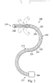
- FIG. 2 illustrates an interventional instrument system 200 which may be used as the interventional instrument system 104 of robotic interventional system 100.
- the interventional instrument system 200 may be used for non-robotic exploratory procedures or in procedures involving traditional manually operated interventional instruments, such as endoscopy.
- the instrument system 200 includes a catheter system 202 coupled to an instrument body 204.
- the catheter system 202 includes an elongated flexible catheter body 216 having a proximal end 217 and a distal end 218.
- the flexible body 216 has an approximately 3 mm outer diameter. Other flexible body outer diameters may be larger or smaller.
- the catheter system 202 includes a shape sensor 222 for determining the position, orientation, speed, pose, and/or shape of the catheter tip at distal end 218 and/or of one or more segments 224 along the body 216. The entire length of the body 216, between the distal end 218 and the proximal end 217 may be effectively divided into the segments 224.
- the shape sensor 222 may be a component of the sensor system 108. If the instrument system 200 is manually operated or otherwise used for non-robotic procedures, the shape sensor 222 may be coupled to a tracking system that interrogates the shape sensor and processes the received shape data. See e.g., FIG. 3 .
- the shape sensor system 222 includes an optical fiber aligned with the flexible catheter body 216 (e.g., provided within an interior channel (not shown) or mounted externally).
- the optical fiber has a diameter of approximately 200 ⁇ m. In other embodiments, the dimensions may be larger or smaller.
- the optical fiber of the shape sensor system 222 forms a fiber optic bend sensor for determining the shape of the catheter system 202.
- optical fibers including Fiber Bragg Gratings (FBGs) are used to provide strain measurements in structures in one or more dimensions.
- FBGs Fiber Bragg Gratings
- Various systems and methods for monitoring the shape and relative position of an optical fiber in three dimensions are described in U.S. Pat. App. No. 11/180,389, filed July, 13, 2005 , disclosing "Fiber optic position and shape sensing device and method relating thereto;" U.S. Provisional Pat. App. No. 60/588,336, filed on Jul. 16, 2004 , disclosing "Fiber-optic shape and relative position sensing;" and U.S. Pat. No. 6,389,187, filed on Jun.
- the shape of the catheter may be determined using other techniques. For example, if the history of the catheter's distal tip pose is stored for an interval of time that is smaller than the period for refreshing the navigation display or for alternating motion (e.g., inhalation and exhalation), the pose history can be used to reconstruct the shape of the device over the interval of time. As another example, historical pose, position, or orientation data may be stored for a known point of an instrument along a cycle of alternating motion, such as breathing.
- This stored data may be used to develop shape information about the catheter.
- a series of positional sensors such as EM sensors, positioned along the catheter can be used for shape sensing.
- a history of data from a positional sensor, such as an EM sensor, on the instrument during a procedure may be used to represent the shape of the instrument, particularly if an anatomical passageway is generally static.
- a wireless device with position or orientation controlled by an external magnetic field may be used for shape sensing. The history of its position may be used to determine a shape for the navigated passageways.
- the optical fiber may include multiple cores within a single cladding.
- Each core may be single-mode with sufficient distance and cladding separating the cores such that the light in each core does not interact significantly with the light carried in other cores.
- the number of cores may vary or each core may be contained in a separate optical fiber.
- an array of FBG's is provided within each core.
- Each FBG comprises a series of modulations of the core's refractive index so as to generate a spatial periodicity in the refraction index.
- the spacing may be chosen so that the partial reflections from each index change add coherently for a narrow band of wavelengths, and therefore reflect only this narrow band of wavelengths while passing through a much broader band.
- the modulations are spaced by a known distance, thereby causing reflection of a known band of wavelengths.
- the spacing of the modulations will change, depending on the amount of strain in the core.
- backscatter or other optical phenomena that vary with bending of the optical fiber can be used to determine strain within each core.
- FBG FBG's produce a reflected wavelength that is a function of the strain on the fiber and its temperature.
- This FBG technology is commercially available from a variety of sources, such as Smart Fibres Ltd. of Bracknell, England.
- Use of FBG technology in position sensors for robotic surgery is described in U.S. Pat. No. 7,930,065, filed July 20, 2006 , disclosing "Robotic Surgery System Including Position Sensors Using Fiber Bragg Gratings,".
- bending of the optical fiber When applied to a multicore fiber, bending of the optical fiber induces strain on the cores that can be measured by monitoring the wavelength shifts in each core.
- bending of the fiber induces different strains on each of the cores. These strains are a function of the local degree of bending of the fiber. For example, regions of the cores containing FBG's, if located at points where the fiber is bent, can thereby be used to determine the amount of bending at those points.
- These data combined with the known spacings of the FBG regions, can be used to reconstruct the shape of the fiber.
- Such a system has been described by Luna Innovations. Inc. of Blacksburg, Va.
- the optical fiber may be used to monitor the shape of at least a portion of the catheter system 202. More specifically, light passing through the optical fiber is processed to detect the shape of the instrument system 202 and for utilizing that information to assist in surgical procedures.
- the sensor system e.g. sensor system 108 or another typed of tracking system as described in FIG. 3
- the sensor system may include an interrogation system for generating and detecting the light used for determining the shape of the interventional instrument system 202. This information, in turn, in can be used to determine other related variables, such as velocity and acceleration of the parts of an interventional instrument.
- the sensing may be limited only to the degrees of freedom that are actuated by the robotic system, or may be applied to both passive (e.g., unactuated bending of the rigid members between joints) and active (e.g., actuated movement of the instrument) degrees of freedom.
- the interventional instrument system may optionally include a position sensor system 220 (e.g., an electromagnetic (EM) sensor system) which may be disabled by an operator or an automated system (e.g., a function of the control system 112) if it becomes unreliable due to, for example, magnetic interference from other equipment in the surgical suite or if other navigation tracking systems are more reliable.
- EM electromagnetic
- the position sensor system 220 may be an EM sensor system that includes one or more conductive coils that may be subjected to an externally generated electromagnetic field. Each coil of the EM sensor system 220 then produces an induced electrical signal having characteristics that depend on the position and orientation of the coil relative to the externally generated electromagnetic field.
- the EM sensor system may be configured and positioned to measure six degrees of freedom, e.g., three position coordinates X, Y, Z and three orientation angles indicating pitch, yaw, and roll of a base point or five degrees of freedom, e.g., three position coordinates X, Y, Z and two orientation angles indicating pitch and yaw of a base point. Further description of an EM sensor system is provided in U.S. Pat. No. 6,380,732, filed August 11, 1999 , disclosing "Six-Degree of Freedom Tracking System Having a Passive Transponder on the Object Being Tracked,".
- the flexible catheter body 216 includes a channel sized and shaped to receive an auxiliary tool 226.
- Auxiliary tools may include, for example, image capture probes, biopsy devices, laser ablation fibers, or other surgical, diagnostic, or therapeutic tools.
- Auxiliary tools may include end effectors having a single working member such as a scalpel, a blade, an optical fiber, or an electrode.
- Other end effectors may include pair or plurality of working members such as forceps, graspers, scissors, or clip appliers, for example. Examples of electrically activated end effectors include electrosurgical electrodes, transducers, sensors, and the like.
- the auxiliary tool 226 may be an image capture probe including a tip portion with a stereoscopic or monoscopic camera disposed near the distal end 218 of the flexible catheter body 216 for capturing images (including video images) that are processed for display.
- the image capture probe may include a cable coupled to the camera for transmitting the captured image data.
- the image capture instrument may be a fiber-optic bundle, such as a fiberscope, that couples to the imaging system.
- the image capture instrument may be single or multi-spectral, for example capturing image data in the visible spectrum, or capturing image data in the visible and infrared or ultraviolet spectrums.
- the flexible catheter body 216 may also house cables, linkages, or other steering controls (not shown) that extend between the instrument body 204 and the distal end 218 to controllably bend or turn the distal end 218 as shown for example by the dotted line versions of the distal end.
- the instrument body 204 may include drive inputs that couple to motorized drive elements of the robotic assembly.
- the instrument body 204 may include gripping features, manual actuators, and other components for manually controlling the motion of the instrument system.
- the catheter system may be steerable or, alternatively, may be non-steerable with no integrated mechanism for operator control of the instrument bending.
- the flexible body 216 can define one or more lumens through which interventional instruments can be deployed and used at a target surgical location.
- the interventional instrument system 202 may be a flexible bronchial instrument, such as a bronchoscope or bronchial catheter for use in examination, diagnosis, biopsy, or treatment of a lung.
- a flexible bronchial instrument such as a bronchoscope or bronchial catheter for use in examination, diagnosis, biopsy, or treatment of a lung.
- the system is also suited for navigation and treatment of other tissues, via natural or surgically created connected passageways, in any of a variety of anatomical systems including the colon, the intestines, the kidneys, the brain, the heart, the circulatory system, or the like.
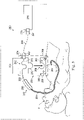
- FIG. 3 illustrates an interventional instrument tracking system 250 according to embodiments of the present disclosure.
- the tracking system 250 includes an interventional instrument 252 with a flexible catheter body 254 and an instrument body 256.
- the interventional instrument 252 may be similar to instrument 200 but in this embodiment, the EM position sensor may be disabled or omitted, as the shape sensing system provides the tracking information used by the clinician to determine the path of the interventional instrument through the patient anatomy.
- An optical fiber shape sensor 253 extends within the interventional instrument 252.
- the tracking system 250 also includes a sensor device 258.
- the sensor device 258 includes a fiduciary apparatus 260 and a reference body 262.
- the fiduciary apparatus 260 includes a surface 264 that is removably attached to the patient P using an adhesive or other chemical or mechanical fixation mechanism.
- the fiduciary apparatus 260 is attached to an external surface of the patient anatomy, but in alternative embodiments, the fiduciary apparatus may be attached to the internal patient anatomy, e.g., trans-nasal, trans-rectal, trans-vaginal, trans-esophageal. In still other alternatives, the fiduciary apparatus 260 may be attached to a temporary implant such as a stent.
- the fiduciary apparatus 260 can include at least one fiducial marking 266 visible with imaging technology such as fluoroscopy or CT. Examples of fiduciary marker design are provided in U.S. Pat. App. No. 12/428,657, filed April 23, 2009 , disclosing "Fiducial Marker Design and Detection for Locating Surgical Instrument in Images," .
- the fiducial marking may have sufficient detail to provide full three dimensional pose registration.
- the fiduciary marking may have an "L"-shape with uneven link lengths that allow for three-dimensional pose registration.
- the fiduciary apparatus 260 can include features (e.g., grooves, protrusions, or other shapes) that are visible under imaging technology and can act as fiducials. In various other embodiments, the fiduciary apparatus 260 itself can act as a fiducial, and in some embodiments may have a shape that facilitates three-dimensional pose determination.
- the fiduciary apparatus 260 further includes a sensor docking feature 268 configured to mate with a mating portion 270 of the reference body 262.
- the sensor docking feature 268 may include one or more recesses, protrusions, mechanical fasteners, adhesive fasteners, magnetic fasteners, or other components for removably connecting the fiduciary apparatus 260 to the reference body 262.
- the sensor docking feature 268 and the mating portion 270 maintain the fiduciary apparatus 260 and the reference body 262 in a known predefined and fixed spatial relationship.
- FIG. 4 illustrates an alternative embodiment of a sensor device 300 including a fiduciary apparatus 302 and a reference body 304.
- a plurality of sensor docking features 306 of the fiduciary apparatus 302 align with and attach to mating portions 308 of the reference body 304.
- the reference body 262 include a sensor holder 272 configured to hold a reference portion 251 the shape sensor fiber 253 in a predefined reference shape.
- the sensor holder 272 is a continuous winding channel that receives the shape sensor fiber 253 and maintains the fiber in a predefined shape configuration relative to the reference body 262.
- the sensor holder may be a series of discrete attachment points to which the sensor fiber may be attached to maintain a predefined shape with respect to the reference body.
- the reference body 262 further includes a sensor connection component 274 in which the sensor fiber 253 terminates for connection to other components of the tracking system 250.
- the tracking system 250 further includes an interrogation system 276 for generating, and detecting the light used to determine the current shape of the shape sensor fiber 253.
- the interrogation system 276 may also process the returned data for display to the clinician.
- the interrogation system 276 includes a connector 278.
- a fiber link 280 extends between connectors 282, 284.
- the optical fiber of the fiber link 280 is unsensed (i.e., the shape of the fiber link is not interrogated) and serves to convey the optical information from the sensed shape sensor 253 to the interrogation system 276.
- the connector 282 of the fiber link 280 is connected to the connector 274 and the connector 284 is connected to the connector 278.
- the fiduciary apparatus 260 is attached to the patient P. Pre-operative or intraoperative imaging of the patient P is conducted with the fiduciary apparatus 260 attached.
- the fiducial markers 266 are visible in the image and thus provide a reference frame fixed relative to the anatomy of patient P and to any two-dimensional, three-dimensional, or four-dimensional (i.e., moving with time) models of the patient anatomy generated by the images (i.e., fiducial markers 266 define a set of reference points having a known relationship to at least a portion of the model data for the patient anatomy).
- reference body 260 can be coupled to the fiduciary apparatus during the pre-operative imaging of the patient P, such that optional fiducial markers, elements, or even the reference portion 251 if the shape sensor fiber 253 can be used as fiducials.
- the reference body 262 is coupled to the fiduciary apparatus 260 and is held in a predefined configuration relative to the fiduciary apparatus by the docking feature 268 and the mating portion 270.
- the reference portion 251 of the shape sensor fiber 253 provides a known pose of the proximal end of the shape sensor fiber relative to the fiduciary apparatus 260.
- the interrogation system 276 interrogates the shape sensor fiber 253 to determine the pose of the distal tip and the shape of the flexible catheter body 254.
- This sensed relative pose and shape data for the catheter body 254 is known relative to the reference portion 251 of the shape sensor fiber, which is registered to the fiduciary apparatus 260.
- processing the relative pose and shape information for the catheter body 254 with the registration information for the reference portion 251 of the shape sensor fiber provides the pose and shape of the catheter body 254 relative to the patient P.
- the configuration of the reference body and the fiduciary apparatus may variable but with a measurable variation.
- This configuration is also known but is measurable instead of predefined.
- the fiduciary apparatus and the reference body may be spaced apart by a small variable distance but the small distance may be continuously monitored and recorded by a sensor-based variation tracking system including capacitive sensors, piezo-electric sensors, or optical sensors.
- the measurable variability may be an insertion direction distance which may be measured, for example using a motor encoder.
- FIG. 5 illustrates a method 320 for using the interventional instrument tracking system 250.
- a processing system receives a model of an anatomic structure of patient P.
- the model is generated from images of the patient P taken with the fiduciary apparatus 260 attached.
- the model defines an image reference frame.
- the fiducial markings 266 are visible in the model.
- the fiducial apparatus 260 is coupled to the reference body 262.
- the reference portion 251 of the shape sensor fiber 253 is thus retained in a predefined configuration relative to the fiducial apparatus 260. In this way, the reference portion 251 is registered to the fiducial apparatus 260.
- the shape sensor information is received (in the reference frame of the shape sensor fiber 253) for processing.
- the pose of the distal end (or any other portion) of the shape sensor fiber 253 is determined in the image reference frame based on a registration between the image reference frame and the reference frame of the shape sensor 253.
- an image from the image reference frame that corresponds to the pose of the distal end of the flexible body 254 is displayed.
- the image may be of the distal end of the flexible body 254 superimposed on an image from the patient model.
- the patient model may be updated based on the shape sensor information (e.g., by fitting the patient model to the pose of flexible body 254).
- the image may be a view from inside the patient model corresponding to the view from the distal end of the flexible body.
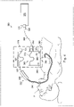
- FIG. 6 illustrates an interventional instrument tracking system 350 according to embodiments of the present disclosure.
- the tracking system 350 includes an interventional instrument 352 with a flexible catheter body 354 and an instrument body 356.
- An optical fiber shape sensor 353 extends within the interventional instrument 352.
- the tracking system 350 also includes a sensor device 358.
- the sensor device 358 includes a fiduciary apparatus 360 with a surface 364 that is removably attached to the patient P using an adhesive or other chemical or mechanical fixation mechanism.
- the fiduciary apparatus 360 includes at least one fiducial marking 366 visible with imaging technology such as fluoroscopy or CT.
- the fiduciary apparatus 360 can include features, that can physical features that can be used as fiducials, or can even itself be a fiducial.
- the fiduciary apparatus 360 also includes a docking feature 373 for mating with a connector 374 of the shape sensor 353.
- the fiduciary apparatus 360 includes a sensor holder 372 configured to dock a reference portion 351 of the shape sensor fiber 353, holding the portion 351 in a predefined reference shape.
- the sensor holder 372 is a continuous winding channel that receives the reference portion 351 of the shape sensor fiber 253 and maintains the fiber in a known predefined shape configuration relative to the fiduciary apparatus 360.
- a sensor connection component 274 terminates the sensor fiber 353 and is removably connectable to the mating docking feature 373.
- the known configuration may be measurably variable as previously described.
- the tracking system 350 further includes an interrogation system 376 for generating, and detecting the light used to determine the current shape of the shape sensor fiber 353.
- the interrogation system 376 may also process the returned data for display to the clinician.
- the interrogation system 376 includes a connector 378.
- a fiber link 380 extends between connectors 382, 384.
- the optical fiber of the fiber link 380 is unsensed (i.e., the shape of the fiber link is not interrogated) and serves to convey the optical information from the sensed shape sensor 353 to the interrogation system 376.
- the connector 382 of the fiber link 380 is connected to the connector 374 and the connector 384 is connected to the connector 378.
- the connectors 374, 382 are connected within a portion of the fiduciary apparatus 360.
- the fiduciary apparatus 360 is attached to the patient P. Pre-operative or intraoperative imaging of the patient P is conducted with the fiduciary apparatus 360 attached. If present, the fiducial markers 366 are visible in the image and thus provide a reference fixed relative to the anatomy of patient P and to any two or three-dimensional models of the patient anatomy generated by the images. In other embodiments, alternative fiducial elements on fiduciary apparatus 360, such as features like sensor holder 372, the reference portion 351 of shape sensor fiber 353 positioned in sensor holder 372, or even fiduciary apparatus 360 itself can be imaged to establish the fixed patient reference.
- the reference portion 351 of the shape sensor fiber 353 is placed in the sensor holder 372 with the connector 374 connected to the connector 382.
- the reference portion 351 is thus held fixed in the predefined configuration of the sensor holder 372 relative to the fiduciary apparatus 360.
- the reference portion 351 of the shape sensor fiber 353 provides a known orientation of the proximal end of the shape sensor fiber relative to the fiduciary apparatus 360.
- the interrogation system 376 interrogates the shape sensor fiber 353 to determine the pose of the distal tip and the shape of the flexible catheter body 354.
- This sensed relative pose and shape data for the catheter body 354 is known relative to the fiber reference portion 351, which is registered to the fiduciary apparatus 360.
- processing the relative pose and shape information for the catheter body 354 with the registration information for the reference portion 351 of the shape sensor fiber provides the pose and shape of the catheter body 354 relative to the patient P.
- FIG. 7 illustrates a method 400 for using the interventional instrument tracking system 350.
- a processing system receives a model of an anatomic structure of patient P.
- the model is generated from images of the patient P taken with the fiduciary apparatus 360 attached.
- the model defines an image reference frame.
- the fiducial markings 366 are visible in the model.
- the reference portion 351 is coupled to the fiduciary apparatus 360.
- the reference portion 351 of the shape sensor fiber 353 is thus retained in a predefined configuration relative to the fiducial apparatus 360. In this way, the reference portion 351 is registered to the fiducial apparatus 360.
- the shape sensor information is received (in the reference frame of the shape sensor fiber 353) for processing.
- the pose of the distal end (or any other portion) of the shape sensor fiber 353 is determined in the image reference frame based on a correlation between the image reference frame and the reference frame of the shape sensor 353.
- an image from the image reference frame that corresponds to the pose of the distal end of the flexible body 354 is displayed.
- the image may be of the distal end of the flexible body 354 superimposed on an image from the patient model.
- the patient model may be updated based on the shape sensor information (e.g., by fitting the patient model to the pose of flexible body 254).
- the image may be a view from inside the patient model corresponding to the view from the distal end of the flexible body.
- FIG. 8 illustrates an interventional instrument tracking system 450 according to embodiments of the present disclosure.
- the tracking system 450 includes an interventional instrument 452 with a flexible catheter body 454 and an instrument body 456.
- An optical fiber shape sensor 453 extends within the interventional instrument 452.
- a proximal end of the shape sensor 453 terminates with a sensor connection component 451.
- the tracking system 450 also includes a sensor device 458.
- the sensor device 458 includes a fiduciary apparatus 460 and a reference fixture 462.
- the fiduciary apparatus 460 includes a surface 464 that is removably attached to the patient P using an adhesive or other chemical or mechanical fixation mechanism.
- the fiduciary apparatus 460 can include at least one fiducial marking 466 visible with imaging technology such as fluoroscopy or CT.
- the fiduciary apparatus 360 can include physical features that can be used as fiducials, or can even itself be a fiducial.
- An optical fiber shape sensor 470 extends from the fiduciary apparatus 460.
- the fiduciary apparatus 460 includes a sensor holder 472 that serves as a docking feature configured to mate with and hold a reference portion 471 of the shape sensor fiber 470 in a predefined reference shape.
- the sensor holder 472 is a continuous winding channel that receives the shape sensor fiber 470 and maintains the reference portion 471 of the fiber in a predefined shape configuration relative to the fiduciary apparatus 460.
- the proximal end of the sensor fiber 470 terminates with a sensor connection component 474.
- the reference portion 471 of the fiber 470 may serve as the fiducial marking as it is fixed with respect to the fiduciary apparatus and may be visible with the imaging technology.
- the shape sensor 470 may be omitted or supplemented by other components for measuring the relative pose between the fiduciary apparatus 460 and the reference fixture 462.
- Any of a variety of sensor-based tracking systems may be used to track the relative pose of the reference fixture 462 to the fiduciary apparatus 460.
- Such tracking systems may include capacitive sensors, piezo-electric sensors, or optical sensors.
- the tracking system 450 further includes an interrogation system 476 for generating and detecting the light used to determine the current shapes of the shape sensor fiber 453 and the shape sensor fiber 470.
- the interrogation system 476 may also process the returned data for display to the clinician.
- the interrogation system 476 includes connector 478, 479.
- a fiber link 480 extends between connectors 482, 484.
- a fiber link 486 extends between connectors 488, 490.
- the optical fiber of the fiber links 480, 486 are unsensed (i.e., the shape of the fiber link is not interrogated) and serves to convey optical information between the sensed shape sensors 453, 470 and the interrogation system 476.
- the fiduciary apparatus 460 is attached to the patient P. Pre-operative or intraoperative imaging of the patient P is conducted with the fiduciary apparatus 460 attached to the patient anatomy.
- the shape sensor fiber 470 may be attached to the fiduciary apparatus 460 during imaging. If present, the fiducial markers 466 are visible in the image and thus provide a reference fixed relative to the anatomy of patient P and to any two or three-dimensional models of the patient anatomy generated by the images.
- alternative fiducial elements on fiduciary apparatus 460 such as features like sensor holder 472, the reference portion 471 of shape sensor fiber 470 positioned in sensor holder 472, or even fiduciary apparatus 460 itself can be imaged to establish the fixed patient reference.
- the proximal end of the sensor fiber 470 and the attached connector 474 are coupled to the reference fixture 462.
- the proximal end of the sensor fiber 453 and the attached connector 451 are also coupled to the reference fixture 462.
- the reference fixture holds the proximal ends of the sensor fibers 470, 451 in fixed positions and orientations relative to each other and to the reference fixture.
- the connector 482 of the fiber link 480 is connected to the connector 451 and the connector 484 is connected to the connector 478 of the interrogation system 476.
- the connector 488 of the fiber link 486 is connected to the connector 474 and the connector 490 is connected to the connector 479 of the interrogation system 476.
- the interrogation system 476 interrogates the shape sensor fiber 453 to determine the pose of the distal tip and the shape of the flexible catheter body 454.
- the interrogation system 476 also interrogates the shape sensor fiber 470 to determine the pose of the reference portion 471 of the shape sensor fiber 470.
- the sensed relative pose and shape data for the catheter body 454 is known relative to the reference fixture 451, and the relative pose and shape data for the reference portion 471 is known relative to the reference fixture 462. Because the connectors 451, 474 are fixed relative to each other and with respect to the reference fixture 462, the reference fixture provides a fixed registration between the shape sensor fibers 453, 470.
- processing the relative pose and shape information for the catheter body 454 with the registration information for the reference portion 471 of the shape sensor fiber 470 provides the pose and shape of the catheter body 454 relative to the patient P.
- FIG. 9 illustrates a method 500 for using the interventional instrument tracking system 450.
- a processing system receives a model of an anatomic structure of patient P.
- the model is generated from images of the patient P taken with the fiduciary apparatus 460 attached.
- the model defines an image reference frame.
- the fiducial markings 466 are visible in the model.
- the shape sensor fiber 453 is coupled to the reference fixture 462, and the shape sensor fiber 470 is coupled to the reference fixture 462.
- shape sensor information is received from shape sensor fiber 470 (in the reference frame of the shape sensor fiber 470) for processing.
- shape sensor information is received from shape sensor fiber 453 (in the reference frame of the shape sensor 453 fiber) for processing.
- the pose of the distal end of the shape sensor fiber 353 is determined in the image reference frame based on a correlation between the image reference frame, the reference frame of the shape sensor 353, and the reference frame of the shape sensor 470.
- an image from the image reference frame that corresponds to the pose of the distal end of the flexible body 454 is displayed.
- the image may be of the distal end of the flexible body 454 superimposed on an image from the patient model.
- the image may be a view from inside the patient model corresponding to the view from the distal end of the flexible body.
- FIG. 10 illustrates an interventional instrument tracking system 550 according to embodiments of the present disclosure.
- the tracking system 550 includes an interventional instrument 552 with a flexible catheter body 554 and an instrument body 556.
- An optical fiber shape sensor 553 is separate from and sized for insertion into the interventional instrument 552.
- the tracking system 550 also includes a sensor device 558.
- the sensor device 558 includes a fiduciary apparatus 560 and a reference body 562.
- the fiduciary apparatus 560 includes a surface 564 that is removably attached to the patient P using an adhesive or other chemical or mechanical fixation mechanism.
- the fiduciary apparatus 560 includes at least one fiducial marking 566 visible with imaging technology such as fluoroscopy or CT.
- the fiduciary apparatus 560 further includes a sensor docking feature 568 configured to mate with a mating portion 570 of the reference body 562.
- the sensor docking feature 568 may include one or more recesses, protrusions, mechanical fasteners, adhesive fasteners, magnetic fasteners, or other components for removably connecting the fiduciary apparatus 560 to the reference body 562.
- the sensor docking feature 568 and the mating portion 570 maintain the fiduciary apparatus 560 and the reference body 562 in a fixed, predefined spatial relationship.
- the reference body 562 include a sensor holder 572 configured to hold a reference portion 551 of the shape sensor fiber 553 in a predefined reference shape.
- the sensor holder 572 is a continuous winding channel that receives the shape sensor fiber 553 and maintains the fiber in a predefined shape configuration relative to the reference body 562.
- the sensor holder may be a series of discrete attachment points to which the sensor fiber may be attached to maintain a known, predefined shape with respect to the reference body.
- the reference body 562 further includes a sensor connection component 574 in which the sensor fiber 553 terminates for connection to other components of the tracking system 550.
- the known configuration may be measurably variable as previously described.
- the tracking system 550 further includes an interrogation system 576 for generating, and detecting the light used to determine the current shape of the shape sensor fiber 553.
- the interrogation system 576 may also process the returned data for display to the clinician.
- the interrogation system 576 includes a connector 578.
- a fiber link 580 extends between connectors 582, 584.
- the optical fiber of the fiber link 580 is unsensed (i.e., the shape of the fiber link is not interrogated) and serves to convey the optical information from the sensed shape sensor 553 to the interrogation system 576.
- the connector 582 of the fiber link 580 is connected to the connector 574 and the connector 584 is connected to the connector 578.
- the fiduciary apparatus 560 is attached to the patient P. Pre-operative or intraoperative imaging of the patient P is conducted with the fiduciary apparatus 560 attached.
- the fiducial markers 566 are visible in the image and thus provide a reference fixed relative to the anatomy of patient P and to any two or three-dimensional models of the patient anatomy generated by the images.
- the sensor fiber 553 is inserted into the flexible catheter body 554.
- the reference body 562 is coupled to the fiduciary apparatus 560 and is held in a predefined configuration relative to the fiduciary apparatus by the docking feature 568 and the mating portion 570.
- the reference portion 551 of the shape sensor fiber 553 provides a known orientation of the proximal end of the shape sensor fiber relative to the fiduciary apparatus 560.
- the interrogation system 576 interrogates the shape sensor fiber 553 to determine the pose of the distal tip and the shape of the flexible catheter body 554.
- This sensed relative pose and shape data for the catheter body 554 is known relative to the reference portion 551 of the shape sensor fiber, which is registered to the fiduciary apparatus 560.
- processing the relative pose and shape information for the catheter body 554 with the registration information for the reference portion 551 of the shape sensor fiber provides the pose and shape of the catheter body 554 relative to the patient P. Further details of the method processing information from the sensor fiber 553 are similar to those described for FIG. 5 .
- the sensor fiber 553 is separable from the flexible catheter body and thus, the sensor fiber 553 may be used with other types of instruments including bronchoscopes or other devices that include a lumen sized to receive the fiber 553.
- One or more elements in embodiments of the invention may be implemented in software to execute on a processor of a computer system such as control system 112.
- the elements of the embodiments of the invention are essentially the code segments to perform the necessary tasks.
- the program or code segments can be stored in a processor readable storage medium or device that may have been downloaded by way of a computer data signal embodied in a carrier wave over a transmission medium or a communication link.
- the processor readable storage device may include any medium that can store information including an optical medium, semiconductor medium, and magnetic medium.
- Processor readable storage device examples include an electronic circuit; a semiconductor device, a semiconductor memory device, a read only memory (ROM), a flash memory, an erasable programmable read only memory (EPROM); a floppy diskette, a CD-ROM, an optical disk, a hard disk, or other storage device,
- the code segments may be downloaded via computer networks such as the Internet, intranet, etc.
Description
- This application claims the benefit of
U.S. Provisional Application 61/799,524 filed March 15, 2013 - The present disclosure is directed to systems and methods for navigating a patient anatomy to conduct a minimally invasive procedure, and more particularly to systems and methods using shape sensor systems to track interventional instruments.
- Minimally invasive medical techniques are intended to reduce the amount of tissue that is damaged during interventional procedures, thereby reducing patient recovery time, discomfort, and deleterious side effects. Such minimally invasive techniques may be performed through natural orifices in a patient anatomy or through one or more surgical incisions. Through these natural orifices or incisions clinicians may insert interventional instruments (including surgical, diagnostic, therapeutic, or biopsy instruments) to reach a target tissue location. To reach the target tissue location, a minimally invasive interventional instrument may navigate natural or surgically created passageways in anatomical systems such as the lungs, the colon, the intestines, the kidneys, the heart, the circulatory system, or the like. In existing systems, electromagnetic (EM) navigation may be used to track the movement of interventional instruments through a patient anatomy. Although EM navigation systems are useful for many procedures, they may be subject to magnetic interference from other equipment in the surgical suite. For example, a C-arm of a fluoroscopic imaging system or metal instruments may generate magnetic interference with EM navigation systems, causing unacceptable errors in the tracking of an interventional instrument. Improved navigation systems and methods are needed for tracking interventional instruments in surgical environments, including in environments where EM navigation is not suitable or may be compromised.
-
EP 2 436 333 A1 discloses a surgical navigation system is disclosed including a camera that is fixedly attached to a patient. The camera space merges with the patient space and thereby eliminates the need for a separate patient tracker. The surgical navigation system calculates the position of a surgical tool with a tracking device in view of the camera and shows on a display device the position of the surgical tool with respect to the patient superimposed and in correlation with a scan image of the patient. -
US 2002/0058864 A1 relates to devices and methods that improve the quality of optic measurements from surfaces such as skin and biological materials. -
US 2009/137952 A1 discloses Robotic medical instrument systems and associated methods utilizing an optical fiber sensors such as Bragg sensor optical fibers. In one configuration, an optical fiber is coupled to an elongate instrument body and includes a fiber core having one or more Bragg gratings. A controller is configured to initiate various actions in response thereto. For example, a controller may generate and display a graphical representation of the instrument body and depict one or more position and/or orientation variables thereof, or adjust motors of an instrument driver to reposition the catheter or another instrument. Optical fibers having Bragg gratings may also be utilized with other system components including a plurality of working instruments that are positioned within a sheath lumen, an instrument driver, localization sensors, and/or an image capture device, and may also be coupled to a patient's body or associated structure that stabilizes the body. - The embodiments of the invention are summarized by the claims that follow the description.
- In one example, a medical tracking system comprises a fiducial apparatus that includes a sensor docking feature configured to mate with a mating portion of a sensor device. The sensor docking feature retains the mating portion in a known configuration. The fiducial apparatus also includes at least one imageable fiducial marker and a surface configured for attachment to an anatomy of a patient.
- In another example, a method for medical instrument tracking comprises receiving a model of an anatomic structure. The model defines an image reference frame and includes an image of at least one fiducial marker. The method further includes registering a reference portion of a first shape sensor device to the plurality of fiducial markers when a fiducial apparatus, including the at least one fiducial marker, is coupled to the first shape sensor device. The reference portion of the first shape sensor device is retained in a known configuration relative to the at least one fiducial marker. The method further comprises receiving first shape sensor information in a first sensor reference frame from a first shape sensor of the first shape sensor device and determining a pose of the first shape sensor in the image reference frame based on a correlation between the image reference frame and the first sensor reference frame.
- A method for medical instrument tracking comprises receiving a model of an anatomic structure. The model defining an image reference frame and including a model of at least one fiducial marker. The method further includes receiving first shape sensor information in a first reference frame from a first shape sensor including a reference portion held in a known configuration with respect to the at least one fiducial marker. The method further includes receiving second shape sensor information in a second reference frame from a second shape sensor positioned within the anatomic structure. The method further includes determining a pose of the second shape sensor in the image reference frame based on a correlation between the first reference frame, the second reference frame, and the image reference frame.
- Additional aspects, features, and advantages of the present disclosure will become apparent from the following detailed description.
- Aspects of the present disclosure are best understood from the following detailed description when read with the accompanying figures. It is emphasized that, in accordance with the standard practice in the industry, various features are not drawn to scale. In fact, the dimensions of the various features may be arbitrarily increased or reduced for clarity of discussion. In addition, the present disclosure may repeat reference numerals and/or letters in the various examples. This repetition is for the purpose of simplicity and clarity and does not in itself dictate a relationship between the various embodiments and/or configurations discussed.
-
FIG. 1 is a robotic interventional system, in accordance with an embodiment of the present disclosure. -
FIG. 2 illustrates an interventional instrument system utilizing aspects of the present disclosure. -
FIG. 3 illustrates an interventional instrument system with a tracking system according to an embodiment of the present disclosure. -
FIG. 4 illustrates a sensor device according to an embodiment of the present disclosure. -
FIG. 5 illustrates a method of use for an interventional instrument tracking system according to an embodiment of the present disclosure. -
FIG. 6 illustrates an interventional instrument system with a tracking system according to another embodiment of the present disclosure. -
FIG. 7 illustrates a method of use for an interventional instrument tracking system according to another embodiment of the present disclosure. -
FIG. 8 illustrates an interventional instrument system with a tracking system according to another embodiment of the present disclosure. -
FIG. 9 illustrates a method of use for an interventional instrument tracking system according to another embodiment of the present disclosure. -
FIG. 10 illustrates an interventional instrument system with a tracking system according to other embodiments of the present disclosure. - In the following detailed description of the aspects of the invention, numerous specific details are set forth in order to provide a thorough understanding of the disclosed embodiments. However, it will be obvious to one skilled in the art that the embodiments of this disclosure may be practiced without these specific details. In other instances well known methods, procedures, components, and circuits have not been described in detail so as not to unnecessarily obscure aspects of the embodiments of the invention. And, to avoid needless descriptive repetition, one or more components or actions described in accordance with one illustrative embodiment can be used or omitted as applicable from other illustrative embodiments.
- The embodiments below will describe various instruments and portions of instruments in terms of their state in three-dimensional space. As used herein, the term "position" refers to the location of an object or a portion of an object in a three-dimensional space (e.g., three degrees of translational freedom along Cartesian X, Y, Z coordinates). As used herein, the term "orientation" refers to the rotational placement of an object or a portion of an object (three degrees of rotational freedom - e.g., roll, pitch, and yaw). As used herein, the term "pose" refers to the position of an object or a portion of an object in at least one degree of translational freedom and to the orientation of that object or portion of the object in at least one degree of rotational freedom (up to six total degrees of freedom). As used herein, the term "shape" refers to a set of poses, positions, or orientations measured along an elongated object.
- Referring to
FIG. 1 of the drawings, a robotic interventional system for use in, for example, surgical, diagnostic, therapeutic, or biopsy procedures, is generally indicated by thereference numeral 100. As shown inFIG. 1 , the roboticinterventional system 100 generally includes arobotic assembly 102 mounted to or near an operating table O on which a patient P is positioned. Aninterventional instrument system 104 is operably coupled to therobotic assembly 102. Anoperator input system 106 allows a surgeon or clinician S to view the surgical site and to control the operation of theinterventional instrument system 104. - The
operator input system 106 may be located at a clinician's console which is usually located in the same room as operating table O. However, it should be understood that the surgeon or clinician S can be located in a different room or a completely different building from the patient P.Operator input system 106 generally includes one or more control device(s) for controlling theinterventional instrument system 104. The control device(s) may include any number of a variety of input devices, such as hand grips, joysticks, trackballs, data gloves, trigger-guns, hand-operated controllers, voice recognition devices, touch screens, body motion or presence sensors, or the like. In some embodiments, the control device(s) will be provided with the same degrees of freedom as the interventional instruments of the robotic assembly to provide the clinician with telepresence, or the perception that the control device(s) are integral with the instruments so that the clinician has a strong sense of directly controlling instruments. In other embodiments, the control device(s) may have more or fewer degrees of freedom than the associated interventional instruments and still provide the clinician with telepresence. In some embodiments, the control device(s) are manual input devices which move with six degrees of freedom, and which may also include an actuatable handle for actuating instruments (for example, for closing grasping jaws, applying an electrical potential to an electrode, delivering a medicinal treatment, or the like). - The
robotic assembly 102 supports theinterventional instrument system 104 and may comprise a kinematic structure of one or more non-servo controlled links (e.g., one or more links that may be manually positioned and locked in place, generally referred to as a set-up structure) and a robotic manipulator. Therobotic assembly 102 includes plurality of actuators (e.g., motors) that drive inputs on theinterventional instrument 104. These motors actively move in response to commands from the control system (e.g., control system 112). The motors include drive systems which when coupled to theinterventional instrument 104 may advance the interventional instrument into a naturally or surgically created anatomical orifice and/or may move the distal end of the interventional instrument in multiple degrees of freedom, which may include three degrees of linear motion (e.g., linear motion along the X, Y, Z Cartesian axes) and three degrees of rotational motion (e.g., rotation about the X, Y, Z Cartesian axes). Additionally, the motors can be used to actuate an articulable end effector of the instrument for grasping tissue in the jaws of a biopsy device or the like. - The robotic
interventional system 100 also includes asensor system 108 with one or more sub-systems for receiving information about the instruments of the robotic assembly. Such sub-systems may include a position sensor system (e.g., an electromagnetic (EM) sensor system); a shape sensor system for determining the position, orientation, speed, pose, and/or shape of the catheter tip and/or of one or more segments along a flexible body ofinstrument 104; and/or a visualization system for capturing images from the distal end of the catheter system. - The robotic
interventional system 100 also includes adisplay system 110 for displaying an image of the surgical site andinterventional instruments 104 generated by sub-systems of thesensor system 108. Thedisplay 110 and theoperator input system 106 may be oriented so the operator can control theinterventional instrument system 104 and theoperator input system 106 as if viewing the workspace in substantially true presence. True presence means that the displayed tissue image appears to an operator as if the operator was physically present at the image location and directly viewing the tissue from the perspective of the image. - Alternatively or additionally,
display system 110 may present images of the surgical site recorded and/or modeled preoperatively using imaging technology such as computerized tomography (CT), magnetic resonance imaging (MRI), fluoroscopy, thermography, ultrasound, optical coherence tomography (OCT), thermal imaging, impedance imaging, laser imaging, nanotube X-ray imaging, or the like. The presented preoperative images may include two-dimensional, three-dimensional, or four-dimensional (including e.g., time based or velocity based information) images and models. - In some embodiments, the
display system 110 may display a virtual visualization image in which the actual location of the interventional instrument is registered (e.g., dynamically referenced) with preoperative or concurrent images to present the clinician with a virtual image of the internal surgical site at the location of the tip of the surgical instrument. - In other embodiments, the
display system 110 may display a virtual visualization image in which the actual location of the interventional instrument is registered with prior images (including preoperatively recorded images) or concurrent images to present the clinician with a virtual image of an interventional instrument at the surgical site. An image of a portion of theinterventional instrument 104 may be superimposed on the virtual image to assist the clinician controlling the interventional instrument. - The robotic
interventional system 100 also includes acontrol system 112. Thecontrol system 112 includes at least one processor (not shown), and typically a plurality of processors, for effecting control between theinterventional instrument system 104, theoperator input system 106, thesensor system 108, and thedisplay system 110. Thecontrol system 112 also includes programmed instructions (e.g., a computer-readable medium storing the instructions) to implement some or all of the methods described herein. Whilecontrol system 112 is shown as a single block in the simplified schematic ofFig. 1 , the system may comprise a number of data processing circuits with a portion of the processing optionally being performed on or adjacent therobotic assembly 102, a portion being performed at theoperator input system 106, and the like. Any of a wide variety of centralized or distributed data processing architectures may be employed. Similarly, the programmed instructions may be implemented as a number of separate programs or subroutines, or they may be integrated into a number of other aspects of the robotic systems described herein. In one embodiment,control system 112 supports wireless communication protocols such as Bluetooth, IrDA, HomeRF, IEEE 802.11, DECT, and Wireless Telemetry. - In some embodiments,
control system 112 may include one or more servo controllers to provide force and torque feedback from theinterventional instrument system 104 to one or more corresponding servomotors for theoperator input system 106. The servo controller(s) may also transmit signals instructingrobotic assembly 102 to move theinterventional instruments 104 which extend into an internal surgical site within the patient body via openings in the body. Any suitable conventional or specialized servo controller may be used. A servo controller may be separate from, or integrated with,robotic assembly 102. In some embodiments, the servo controller and robotic assembly are provided as part of a robotic arm cart positioned adjacent to the patient's body. - The
control system 112 may further include a virtual visualization system to provide navigation assistance to theinterventional instruments 104. Virtual navigation using the virtual visualization system is based upon reference to an acquired dataset associated with the three dimensional structure of the anatomical passageways. More specifically, the virtual visualization system processes images of the surgical site recorded and/or modeled using imaging technology such as computerized tomography (CT), magnetic resonance imaging (MRI), fluoroscopy, thermography, ultrasound, optical coherence tomography (OCT), thermal imaging, impedance imaging, laser imaging, nanotube X-ray imaging, or the like. Software is used to convert the recorded images into a two dimensional or three dimensional model of a partial or an entire anatomical organ or anatomical region. The model describes the various locations and shapes of the passageways and their connectivity. The images used to generate the model may be recorded preoperatively or intra-operatively during a clinical procedure. In an alternative embodiment, a virtual visualization system may use standard models (i.e., not patient specific) or hybrids of a standard model and patient specific data. The model and any virtual images generated by the model may represent the static posture of a deformable anatomic region during one or more phases of motion (e.g., during an inspiration/ expiration cycle of a lung) or during induced anatomic motion (e.g., patient repositioning or instrument-caused deformation). - During a virtual navigation procedure, the
sensor system 108 may be used to compute an approximate location of the instrument with respect to the patient anatomy. The location can be used to produce both macro-level tracking images of the patient anatomy and virtual internal images of the patient anatomy. Various systems for using fiber optic sensors to register and display an interventional implement together with preoperatively recorded surgical images, such as those from a virtual visualization system, are known. For exampleU.S. Patent Application No. 13/107,562, filed May 13, 2011 - The robotic
interventional system 100 may further include optional operation and support systems (not shown) such as illumination systems, steering control systems, irrigation systems, and/or suction systems. In alternative embodiments, the robotic system may include more than one robotic assembly and/or more than one operator input system. The exact number of manipulator assemblies will depend on the surgical procedure and the space constraints within the operating room, among other factors. The operator input systems may be collocated, or they may be positioned in separate locations. Multiple operator input systems allow more than one operator to control one or more manipulator assemblies in various combinations. -
FIG. 2 illustrates aninterventional instrument system 200 which may be used as theinterventional instrument system 104 of roboticinterventional system 100. Alternatively, theinterventional instrument system 200 may be used for non-robotic exploratory procedures or in procedures involving traditional manually operated interventional instruments, such as endoscopy. - The
instrument system 200 includes acatheter system 202 coupled to aninstrument body 204. Thecatheter system 202 includes an elongatedflexible catheter body 216 having aproximal end 217 and adistal end 218. In one embodiment, theflexible body 216 has an approximately 3 mm outer diameter. Other flexible body outer diameters may be larger or smaller. Thecatheter system 202 includes ashape sensor 222 for determining the position, orientation, speed, pose, and/or shape of the catheter tip atdistal end 218 and/or of one ormore segments 224 along thebody 216. The entire length of thebody 216, between thedistal end 218 and theproximal end 217 may be effectively divided into thesegments 224. If theinstrument system 200 is aninterventional instrument system 104 of a roboticinterventional system 100, theshape sensor 222 may be a component of thesensor system 108. If theinstrument system 200 is manually operated or otherwise used for non-robotic procedures, theshape sensor 222 may be coupled to a tracking system that interrogates the shape sensor and processes the received shape data. See e.g.,FIG. 3 . - The
shape sensor system 222 includes an optical fiber aligned with the flexible catheter body 216 (e.g., provided within an interior channel (not shown) or mounted externally). In one embodiment, the optical fiber has a diameter of approximately 200 µm. In other embodiments, the dimensions may be larger or smaller. - The optical fiber of the
shape sensor system 222 forms a fiber optic bend sensor for determining the shape of thecatheter system 202. In one alternative, optical fibers including Fiber Bragg Gratings (FBGs) are used to provide strain measurements in structures in one or more dimensions. Various systems and methods for monitoring the shape and relative position of an optical fiber in three dimensions are described inU.S. Pat. App. No. 11/180,389, filed July, 13, 2005 U.S. Provisional Pat. App. No. 60/588,336, filed on Jul. 16, 2004 U.S. Pat. No. 6,389,187, filed on Jun. 17, 1998 , disclosing "Optical Fibre Bend Sensor,". In other alternatives, sensors employing other strain sensing techniques such as Rayleigh scattering, Raman scattering, Brillouin scattering, and Fluorescence scattering may be suitable. In other alternative embodiments, the shape of the catheter may be determined using other techniques. For example, if the history of the catheter's distal tip pose is stored for an interval of time that is smaller than the period for refreshing the navigation display or for alternating motion (e.g., inhalation and exhalation), the pose history can be used to reconstruct the shape of the device over the interval of time. As another example, historical pose, position, or orientation data may be stored for a known point of an instrument along a cycle of alternating motion, such as breathing. This stored data may be used to develop shape information about the catheter. Alternatively, a series of positional sensors, such as EM sensors, positioned along the catheter can be used for shape sensing. Alternatively, a history of data from a positional sensor, such as an EM sensor, on the instrument during a procedure may be used to represent the shape of the instrument, particularly if an anatomical passageway is generally static. Alternatively, a wireless device with position or orientation controlled by an external magnetic field may be used for shape sensing. The history of its position may be used to determine a shape for the navigated passageways. - In this embodiment, the optical fiber may include multiple cores within a single cladding. Each core may be single-mode with sufficient distance and cladding separating the cores such that the light in each core does not interact significantly with the light carried in other cores. In other embodiments, the number of cores may vary or each core may be contained in a separate optical fiber.
- In some embodiments, an array of FBG's is provided within each core. Each FBG comprises a series of modulations of the core's refractive index so as to generate a spatial periodicity in the refraction index. The spacing may be chosen so that the partial reflections from each index change add coherently for a narrow band of wavelengths, and therefore reflect only this narrow band of wavelengths while passing through a much broader band. During fabrication of the FBG's, the modulations are spaced by a known distance, thereby causing reflection of a known band of wavelengths. However, when a strain is induced on the fiber core, the spacing of the modulations will change, depending on the amount of strain in the core. Alternatively, backscatter or other optical phenomena that vary with bending of the optical fiber can be used to determine strain within each core.
- Thus, to measure strain, light is sent down the fiber, and characteristics of the returning light are measured. For example, FBG's produce a reflected wavelength that is a function of the strain on the fiber and its temperature. This FBG technology is commercially available from a variety of sources, such as Smart Fibres Ltd. of Bracknell, England. Use of FBG technology in position sensors for robotic surgery is described in
U.S. Pat. No. 7,930,065, filed July 20, 2006 , disclosing "Robotic Surgery System Including Position Sensors Using Fiber Bragg Gratings,". - When applied to a multicore fiber, bending of the optical fiber induces strain on the cores that can be measured by monitoring the wavelength shifts in each core. By having two or more cores disposed off-axis in the fiber, bending of the fiber induces different strains on each of the cores. These strains are a function of the local degree of bending of the fiber. For example, regions of the cores containing FBG's, if located at points where the fiber is bent, can thereby be used to determine the amount of bending at those points. These data, combined with the known spacings of the FBG regions, can be used to reconstruct the shape of the fiber. Such a system has been described by Luna Innovations. Inc. of Blacksburg, Va.
- As described, the optical fiber may be used to monitor the shape of at least a portion of the
catheter system 202. More specifically, light passing through the optical fiber is processed to detect the shape of theinstrument system 202 and for utilizing that information to assist in surgical procedures. The sensor system (e.g. sensor system 108 or another typed of tracking system as described inFIG. 3 ) may include an interrogation system for generating and detecting the light used for determining the shape of theinterventional instrument system 202. This information, in turn, in can be used to determine other related variables, such as velocity and acceleration of the parts of an interventional instrument. The sensing may be limited only to the degrees of freedom that are actuated by the robotic system, or may be applied to both passive (e.g., unactuated bending of the rigid members between joints) and active (e.g., actuated movement of the instrument) degrees of freedom. - The interventional instrument system may optionally include a position sensor system 220 (e.g., an electromagnetic (EM) sensor system) which may be disabled by an operator or an automated system (e.g., a function of the control system 112) if it becomes unreliable due to, for example, magnetic interference from other equipment in the surgical suite or if other navigation tracking systems are more reliable.
- The position sensor system 220 may be an EM sensor system that includes one or more conductive coils that may be subjected to an externally generated electromagnetic field. Each coil of the EM sensor system 220 then produces an induced electrical signal having characteristics that depend on the position and orientation of the coil relative to the externally generated electromagnetic field. In one embodiment, the EM sensor system may be configured and positioned to measure six degrees of freedom, e.g., three position coordinates X, Y, Z and three orientation angles indicating pitch, yaw, and roll of a base point or five degrees of freedom, e.g., three position coordinates X, Y, Z and two orientation angles indicating pitch and yaw of a base point. Further description of an EM sensor system is provided in
U.S. Pat. No. 6,380,732, filed August 11, 1999 , disclosing "Six-Degree of Freedom Tracking System Having a Passive Transponder on the Object Being Tracked,". - The
flexible catheter body 216 includes a channel sized and shaped to receive anauxiliary tool 226. Auxiliary tools may include, for example, image capture probes, biopsy devices, laser ablation fibers, or other surgical, diagnostic, or therapeutic tools. Auxiliary tools may include end effectors having a single working member such as a scalpel, a blade, an optical fiber, or an electrode. Other end effectors may include pair or plurality of working members such as forceps, graspers, scissors, or clip appliers, for example. Examples of electrically activated end effectors include electrosurgical electrodes, transducers, sensors, and the like. In various embodiments, theauxiliary tool 226 may be an image capture probe including a tip portion with a stereoscopic or monoscopic camera disposed near thedistal end 218 of theflexible catheter body 216 for capturing images (including video images) that are processed for display. The image capture probe may include a cable coupled to the camera for transmitting the captured image data. Alternatively, the image capture instrument may be a fiber-optic bundle, such as a fiberscope, that couples to the imaging system. The image capture instrument may be single or multi-spectral, for example capturing image data in the visible spectrum, or capturing image data in the visible and infrared or ultraviolet spectrums. - The
flexible catheter body 216 may also house cables, linkages, or other steering controls (not shown) that extend between theinstrument body 204 and thedistal end 218 to controllably bend or turn thedistal end 218 as shown for example by the dotted line versions of the distal end. In embodiments in which theinstrument system 200 is actuated by a robotic assembly, theinstrument body 204 may include drive inputs that couple to motorized drive elements of the robotic assembly. In embodiments in which theinstrument system 200 is manually operated, theinstrument body 204 may include gripping features, manual actuators, and other components for manually controlling the motion of the instrument system. The catheter system may be steerable or, alternatively, may be non-steerable with no integrated mechanism for operator control of the instrument bending. Also or alternatively, theflexible body 216 can define one or more lumens through which interventional instruments can be deployed and used at a target surgical location. - In various embodiments, the
interventional instrument system 202 may be a flexible bronchial instrument, such as a bronchoscope or bronchial catheter for use in examination, diagnosis, biopsy, or treatment of a lung. The system is also suited for navigation and treatment of other tissues, via natural or surgically created connected passageways, in any of a variety of anatomical systems including the colon, the intestines, the kidneys, the brain, the heart, the circulatory system, or the like. -
FIG. 3 illustrates an interventionalinstrument tracking system 250 according to embodiments of the present disclosure. Thetracking system 250 includes aninterventional instrument 252 with aflexible catheter body 254 and aninstrument body 256. Theinterventional instrument 252 may be similar toinstrument 200 but in this embodiment, the EM position sensor may be disabled or omitted, as the shape sensing system provides the tracking information used by the clinician to determine the path of the interventional instrument through the patient anatomy. An opticalfiber shape sensor 253 extends within theinterventional instrument 252. Thetracking system 250 also includes asensor device 258. Thesensor device 258 includes afiduciary apparatus 260 and areference body 262. Thefiduciary apparatus 260 includes asurface 264 that is removably attached to the patient P using an adhesive or other chemical or mechanical fixation mechanism. In some embodiments, thefiduciary apparatus 260 is attached to an external surface of the patient anatomy, but in alternative embodiments, the fiduciary apparatus may be attached to the internal patient anatomy, e.g., trans-nasal, trans-rectal, trans-vaginal, trans-esophageal. In still other alternatives, thefiduciary apparatus 260 may be attached to a temporary implant such as a stent. - The
fiduciary apparatus 260 can include at least onefiducial marking 266 visible with imaging technology such as fluoroscopy or CT. Examples of fiduciary marker design are provided inU.S. Pat. App. No. 12/428,657, filed April 23, 2009 fiduciary apparatus 260 can include features (e.g., grooves, protrusions, or other shapes) that are visible under imaging technology and can act as fiducials. In various other embodiments, thefiduciary apparatus 260 itself can act as a fiducial, and in some embodiments may have a shape that facilitates three-dimensional pose determination. - The
fiduciary apparatus 260 further includes asensor docking feature 268 configured to mate with amating portion 270 of thereference body 262. Thesensor docking feature 268 may include one or more recesses, protrusions, mechanical fasteners, adhesive fasteners, magnetic fasteners, or other components for removably connecting thefiduciary apparatus 260 to thereference body 262. When connected, thesensor docking feature 268 and themating portion 270 maintain thefiduciary apparatus 260 and thereference body 262 in a known predefined and fixed spatial relationship. -
FIG. 4 illustrates an alternative embodiment of asensor device 300 including afiduciary apparatus 302 and areference body 304. In this embodiment, a plurality of sensor docking features 306 of thefiduciary apparatus 302 align with and attach tomating portions 308 of thereference body 304. - Referring again to
FIG. 3 , thereference body 262 include asensor holder 272 configured to hold areference portion 251 theshape sensor fiber 253 in a predefined reference shape. In this embodiment, thesensor holder 272 is a continuous winding channel that receives theshape sensor fiber 253 and maintains the fiber in a predefined shape configuration relative to thereference body 262. In alternative embodiments, the sensor holder may be a series of discrete attachment points to which the sensor fiber may be attached to maintain a predefined shape with respect to the reference body. Thereference body 262 further includes asensor connection component 274 in which thesensor fiber 253 terminates for connection to other components of thetracking system 250. - The
tracking system 250 further includes aninterrogation system 276 for generating, and detecting the light used to determine the current shape of theshape sensor fiber 253. Theinterrogation system 276 may also process the returned data for display to the clinician. Theinterrogation system 276 includes aconnector 278. Afiber link 280 extends betweenconnectors fiber link 280 is unsensed (i.e., the shape of the fiber link is not interrogated) and serves to convey the optical information from the sensedshape sensor 253 to theinterrogation system 276. In use, theconnector 282 of thefiber link 280 is connected to theconnector 274 and theconnector 284 is connected to theconnector 278. - In use, the
fiduciary apparatus 260 is attached to the patient P. Pre-operative or intraoperative imaging of the patient P is conducted with thefiduciary apparatus 260 attached. Thefiducial markers 266 are visible in the image and thus provide a reference frame fixed relative to the anatomy of patient P and to any two-dimensional, three-dimensional, or four-dimensional (i.e., moving with time) models of the patient anatomy generated by the images (i.e.,fiducial markers 266 define a set of reference points having a known relationship to at least a portion of the model data for the patient anatomy). In various other embodiments,reference body 260 can be coupled to the fiduciary apparatus during the pre-operative imaging of the patient P, such that optional fiducial markers, elements, or even thereference portion 251 if theshape sensor fiber 253 can be used as fiducials. - In any event, before initiating the interventional procedure, the
reference body 262 is coupled to thefiduciary apparatus 260 and is held in a predefined configuration relative to the fiduciary apparatus by thedocking feature 268 and themating portion 270. Thus connected, thereference portion 251 of theshape sensor fiber 253 provides a known pose of the proximal end of the shape sensor fiber relative to thefiduciary apparatus 260. Theinterrogation system 276 interrogates theshape sensor fiber 253 to determine the pose of the distal tip and the shape of theflexible catheter body 254. This sensed relative pose and shape data for thecatheter body 254 is known relative to thereference portion 251 of the shape sensor fiber, which is registered to thefiduciary apparatus 260. Thus, processing the relative pose and shape information for thecatheter body 254 with the registration information for thereference portion 251 of the shape sensor fiber provides the pose and shape of thecatheter body 254 relative to the patient P. - In various alternative embodiments to the above described fixed and predefined configuration of the reference body and fiduciary apparatus, the configuration of the reference body and the fiduciary apparatus may variable but with a measurable variation. This configuration is also known but is measurable instead of predefined. For example, the fiduciary apparatus and the reference body may be spaced apart by a small variable distance but the small distance may be continuously monitored and recorded by a sensor-based variation tracking system including capacitive sensors, piezo-electric sensors, or optical sensors. As another example, the measurable variability may be an insertion direction distance which may be measured, for example using a motor encoder.
-
FIG. 5 illustrates amethod 320 for using the interventionalinstrument tracking system 250. At 322, a processing system receives a model of an anatomic structure of patient P. The model is generated from images of the patient P taken with thefiduciary apparatus 260 attached. The model defines an image reference frame. Thefiducial markings 266 are visible in the model. At 324, thefiducial apparatus 260 is coupled to thereference body 262. Thereference portion 251 of theshape sensor fiber 253 is thus retained in a predefined configuration relative to thefiducial apparatus 260. In this way, thereference portion 251 is registered to thefiducial apparatus 260. At 326, the shape sensor information is received (in the reference frame of the shape sensor fiber 253) for processing. At 328, the pose of the distal end (or any other portion) of theshape sensor fiber 253 is determined in the image reference frame based on a registration between the image reference frame and the reference frame of theshape sensor 253. Optionally, an image from the image reference frame that corresponds to the pose of the distal end of theflexible body 254 is displayed. The image may be of the distal end of theflexible body 254 superimposed on an image from the patient model. In some embodiments, the patient model may be updated based on the shape sensor information (e.g., by fitting the patient model to the pose of flexible body 254). Alternatively, the image may be a view from inside the patient model corresponding to the view from the distal end of the flexible body. -
FIG. 6 illustrates an interventionalinstrument tracking system 350 according to embodiments of the present disclosure. Thetracking system 350 includes aninterventional instrument 352 with aflexible catheter body 354 and aninstrument body 356. An opticalfiber shape sensor 353 extends within theinterventional instrument 352. Thetracking system 350 also includes asensor device 358. Thesensor device 358 includes afiduciary apparatus 360 with asurface 364 that is removably attached to the patient P using an adhesive or other chemical or mechanical fixation mechanism. In various embodiments, thefiduciary apparatus 360 includes at least onefiducial marking 366 visible with imaging technology such as fluoroscopy or CT. In various other embodiments, thefiduciary apparatus 360 can include features, that can physical features that can be used as fiducials, or can even itself be a fiducial. Thefiduciary apparatus 360 also includes adocking feature 373 for mating with aconnector 374 of theshape sensor 353. - The
fiduciary apparatus 360 includes asensor holder 372 configured to dock areference portion 351 of theshape sensor fiber 353, holding theportion 351 in a predefined reference shape. In this embodiment, thesensor holder 372 is a continuous winding channel that receives thereference portion 351 of theshape sensor fiber 253 and maintains the fiber in a known predefined shape configuration relative to thefiduciary apparatus 360. Asensor connection component 274 terminates thesensor fiber 353 and is removably connectable to themating docking feature 373. In various alternative embodiments, the known configuration may be measurably variable as previously described. - The
tracking system 350 further includes aninterrogation system 376 for generating, and detecting the light used to determine the current shape of theshape sensor fiber 353. Theinterrogation system 376 may also process the returned data for display to the clinician. Theinterrogation system 376 includes aconnector 378. Afiber link 380 extends betweenconnectors fiber link 380 is unsensed (i.e., the shape of the fiber link is not interrogated) and serves to convey the optical information from the sensedshape sensor 353 to theinterrogation system 376. In use, theconnector 382 of thefiber link 380 is connected to theconnector 374 and theconnector 384 is connected to theconnector 378. In this embodiment theconnectors fiduciary apparatus 360. - In use, the
fiduciary apparatus 360 is attached to the patient P. Pre-operative or intraoperative imaging of the patient P is conducted with thefiduciary apparatus 360 attached. If present, thefiducial markers 366 are visible in the image and thus provide a reference fixed relative to the anatomy of patient P and to any two or three-dimensional models of the patient anatomy generated by the images. In other embodiments, alternative fiducial elements onfiduciary apparatus 360, such as features likesensor holder 372, thereference portion 351 ofshape sensor fiber 353 positioned insensor holder 372, or evenfiduciary apparatus 360 itself can be imaged to establish the fixed patient reference. - Before initiating the interventional procedure, the
reference portion 351 of theshape sensor fiber 353 is placed in thesensor holder 372 with theconnector 374 connected to theconnector 382. Thereference portion 351 is thus held fixed in the predefined configuration of thesensor holder 372 relative to thefiduciary apparatus 360. Thus connected, thereference portion 351 of theshape sensor fiber 353 provides a known orientation of the proximal end of the shape sensor fiber relative to thefiduciary apparatus 360. Theinterrogation system 376 interrogates theshape sensor fiber 353 to determine the pose of the distal tip and the shape of theflexible catheter body 354. This sensed relative pose and shape data for thecatheter body 354 is known relative to thefiber reference portion 351, which is registered to thefiduciary apparatus 360. Thus, processing the relative pose and shape information for thecatheter body 354 with the registration information for thereference portion 351 of the shape sensor fiber provides the pose and shape of thecatheter body 354 relative to the patient P. -
FIG. 7 illustrates amethod 400 for using the interventionalinstrument tracking system 350. At 402, a processing system receives a model of an anatomic structure of patient P. The model is generated from images of the patient P taken with thefiduciary apparatus 360 attached. The model defines an image reference frame. Thefiducial markings 366 are visible in the model. At 404, thereference portion 351 is coupled to thefiduciary apparatus 360. Thereference portion 351 of theshape sensor fiber 353 is thus retained in a predefined configuration relative to thefiducial apparatus 360. In this way, thereference portion 351 is registered to thefiducial apparatus 360. At 406, the shape sensor information is received (in the reference frame of the shape sensor fiber 353) for processing. At 408, the pose of the distal end (or any other portion) of theshape sensor fiber 353 is determined in the image reference frame based on a correlation between the image reference frame and the reference frame of theshape sensor 353. Optionally, an image from the image reference frame that corresponds to the pose of the distal end of theflexible body 354 is displayed. The image may be of the distal end of theflexible body 354 superimposed on an image from the patient model. In some embodiments, the patient model may be updated based on the shape sensor information (e.g., by fitting the patient model to the pose of flexible body 254). Alternatively, the image may be a view from inside the patient model corresponding to the view from the distal end of the flexible body. -
FIG. 8 illustrates an interventionalinstrument tracking system 450 according to embodiments of the present disclosure. Thetracking system 450 includes aninterventional instrument 452 with aflexible catheter body 454 and aninstrument body 456. An opticalfiber shape sensor 453 extends within theinterventional instrument 452. A proximal end of theshape sensor 453 terminates with asensor connection component 451. Thetracking system 450 also includes asensor device 458. Thesensor device 458 includes afiduciary apparatus 460 and areference fixture 462. Thefiduciary apparatus 460 includes asurface 464 that is removably attached to the patient P using an adhesive or other chemical or mechanical fixation mechanism. In some embodiments, thefiduciary apparatus 460 can include at least onefiducial marking 466 visible with imaging technology such as fluoroscopy or CT. In various other embodiments, thefiduciary apparatus 360 can include physical features that can be used as fiducials, or can even itself be a fiducial. - An optical
fiber shape sensor 470 extends from thefiduciary apparatus 460. Thefiduciary apparatus 460 includes asensor holder 472 that serves as a docking feature configured to mate with and hold areference portion 471 of theshape sensor fiber 470 in a predefined reference shape. In this embodiment, thesensor holder 472 is a continuous winding channel that receives theshape sensor fiber 470 and maintains thereference portion 471 of the fiber in a predefined shape configuration relative to thefiduciary apparatus 460. The proximal end of thesensor fiber 470 terminates with asensor connection component 474. In this embodiment, thereference portion 471 of thefiber 470 may serve as the fiducial marking as it is fixed with respect to the fiduciary apparatus and may be visible with the imaging technology. - In various alternative embodiments, the
shape sensor 470 may be omitted or supplemented by other components for measuring the relative pose between thefiduciary apparatus 460 and thereference fixture 462. Any of a variety of sensor-based tracking systems may be used to track the relative pose of thereference fixture 462 to thefiduciary apparatus 460. Such tracking systems may include capacitive sensors, piezo-electric sensors, or optical sensors. - The
tracking system 450 further includes aninterrogation system 476 for generating and detecting the light used to determine the current shapes of theshape sensor fiber 453 and theshape sensor fiber 470. Theinterrogation system 476 may also process the returned data for display to the clinician. Theinterrogation system 476 includesconnector fiber link 480 extends betweenconnectors fiber link 486 extends betweenconnectors shape sensors interrogation system 476. - In use, the
fiduciary apparatus 460 is attached to the patient P. Pre-operative or intraoperative imaging of the patient P is conducted with thefiduciary apparatus 460 attached to the patient anatomy. In this embodiment, theshape sensor fiber 470 may be attached to thefiduciary apparatus 460 during imaging. If present, thefiducial markers 466 are visible in the image and thus provide a reference fixed relative to the anatomy of patient P and to any two or three-dimensional models of the patient anatomy generated by the images. In other embodiments, alternative fiducial elements onfiduciary apparatus 460, such as features likesensor holder 472, thereference portion 471 ofshape sensor fiber 470 positioned insensor holder 472, or evenfiduciary apparatus 460 itself can be imaged to establish the fixed patient reference. - Before initiating the interventional procedure, the proximal end of the
sensor fiber 470 and the attachedconnector 474 are coupled to thereference fixture 462. The proximal end of thesensor fiber 453 and the attachedconnector 451 are also coupled to thereference fixture 462. The reference fixture holds the proximal ends of thesensor fibers connector 482 of thefiber link 480 is connected to theconnector 451 and theconnector 484 is connected to theconnector 478 of theinterrogation system 476. Theconnector 488 of thefiber link 486 is connected to theconnector 474 and theconnector 490 is connected to theconnector 479 of theinterrogation system 476. Theinterrogation system 476 interrogates theshape sensor fiber 453 to determine the pose of the distal tip and the shape of theflexible catheter body 454. Theinterrogation system 476 also interrogates theshape sensor fiber 470 to determine the pose of thereference portion 471 of theshape sensor fiber 470. The sensed relative pose and shape data for thecatheter body 454 is known relative to thereference fixture 451, and the relative pose and shape data for thereference portion 471 is known relative to thereference fixture 462. Because theconnectors reference fixture 462, the reference fixture provides a fixed registration between theshape sensor fibers catheter body 454 with the registration information for thereference portion 471 of theshape sensor fiber 470 provides the pose and shape of thecatheter body 454 relative to the patient P. -
FIG. 9 illustrates amethod 500 for using the interventionalinstrument tracking system 450. At 502, a processing system receives a model of an anatomic structure of patient P. The model is generated from images of the patient P taken with thefiduciary apparatus 460 attached. The model defines an image reference frame. Thefiducial markings 466 are visible in the model. Theshape sensor fiber 453 is coupled to thereference fixture 462, and theshape sensor fiber 470 is coupled to thereference fixture 462. At 504, shape sensor information is received from shape sensor fiber 470 (in the reference frame of the shape sensor fiber 470) for processing. At 506, shape sensor information is received from shape sensor fiber 453 (in the reference frame of theshape sensor 453 fiber) for processing. At 508, the pose of the distal end of theshape sensor fiber 353 is determined in the image reference frame based on a correlation between the image reference frame, the reference frame of theshape sensor 353, and the reference frame of theshape sensor 470. Optionally, an image from the image reference frame that corresponds to the pose of the distal end of theflexible body 454 is displayed. The image may be of the distal end of theflexible body 454 superimposed on an image from the patient model. Alternatively, the image may be a view from inside the patient model corresponding to the view from the distal end of the flexible body. -
FIG. 10 illustrates an interventionalinstrument tracking system 550 according to embodiments of the present disclosure. Thetracking system 550 includes aninterventional instrument 552 with aflexible catheter body 554 and aninstrument body 556. An opticalfiber shape sensor 553 is separate from and sized for insertion into theinterventional instrument 552. Thetracking system 550 also includes asensor device 558. Thesensor device 558 includes afiduciary apparatus 560 and areference body 562. Thefiduciary apparatus 560 includes asurface 564 that is removably attached to the patient P using an adhesive or other chemical or mechanical fixation mechanism. Thefiduciary apparatus 560 includes at least onefiducial marking 566 visible with imaging technology such as fluoroscopy or CT. Thefiduciary apparatus 560 further includes asensor docking feature 568 configured to mate with amating portion 570 of thereference body 562. Thesensor docking feature 568 may include one or more recesses, protrusions, mechanical fasteners, adhesive fasteners, magnetic fasteners, or other components for removably connecting thefiduciary apparatus 560 to thereference body 562. When connected, thesensor docking feature 568 and themating portion 570 maintain thefiduciary apparatus 560 and thereference body 562 in a fixed, predefined spatial relationship. - The
reference body 562 include a sensor holder 572 configured to hold areference portion 551 of theshape sensor fiber 553 in a predefined reference shape. In this embodiment, the sensor holder 572 is a continuous winding channel that receives theshape sensor fiber 553 and maintains the fiber in a predefined shape configuration relative to thereference body 562. In alternative embodiments, the sensor holder may be a series of discrete attachment points to which the sensor fiber may be attached to maintain a known, predefined shape with respect to the reference body. Thereference body 562 further includes asensor connection component 574 in which thesensor fiber 553 terminates for connection to other components of thetracking system 550. The various alternative embodiments, the known configuration may be measurably variable as previously described. - The
tracking system 550 further includes aninterrogation system 576 for generating, and detecting the light used to determine the current shape of theshape sensor fiber 553. Theinterrogation system 576 may also process the returned data for display to the clinician. Theinterrogation system 576 includes aconnector 578. Afiber link 580 extends betweenconnectors fiber link 580 is unsensed (i.e., the shape of the fiber link is not interrogated) and serves to convey the optical information from the sensedshape sensor 553 to theinterrogation system 576. In use, theconnector 582 of thefiber link 580 is connected to theconnector 574 and theconnector 584 is connected to theconnector 578. - In use, the
fiduciary apparatus 560 is attached to the patient P. Pre-operative or intraoperative imaging of the patient P is conducted with thefiduciary apparatus 560 attached. Thefiducial markers 566 are visible in the image and thus provide a reference fixed relative to the anatomy of patient P and to any two or three-dimensional models of the patient anatomy generated by the images. Before initiating the interventional procedure, thesensor fiber 553 is inserted into theflexible catheter body 554. Thereference body 562 is coupled to thefiduciary apparatus 560 and is held in a predefined configuration relative to the fiduciary apparatus by thedocking feature 568 and themating portion 570. Thus connected, thereference portion 551 of theshape sensor fiber 553 provides a known orientation of the proximal end of the shape sensor fiber relative to thefiduciary apparatus 560. Theinterrogation system 576 interrogates theshape sensor fiber 553 to determine the pose of the distal tip and the shape of theflexible catheter body 554. This sensed relative pose and shape data for thecatheter body 554 is known relative to thereference portion 551 of the shape sensor fiber, which is registered to thefiduciary apparatus 560. Thus, processing the relative pose and shape information for thecatheter body 554 with the registration information for thereference portion 551 of the shape sensor fiber provides the pose and shape of thecatheter body 554 relative to the patient P. Further details of the method processing information from thesensor fiber 553 are similar to those described forFIG. 5 . - In this embodiment, the
sensor fiber 553 is separable from the flexible catheter body and thus, thesensor fiber 553 may be used with other types of instruments including bronchoscopes or other devices that include a lumen sized to receive thefiber 553. - Although the systems and methods of this disclosure have been described for use in the connected bronchial passageways of the lung, they are also suited for navigation and treatment of other tissues, via natural or surgically created connected passageways, in any of a variety of anatomical systems including the colon, the intestines, the kidneys, the brain, the heart, the circulatory system, or the like. The methods and embodiments of this disclosure are also suitable for non-interventional applications.
- One or more elements in embodiments of the invention may be implemented in software to execute on a processor of a computer system such as
control system 112. When implemented in software, the elements of the embodiments of the invention are essentially the code segments to perform the necessary tasks. The program or code segments can be stored in a processor readable storage medium or device that may have been downloaded by way of a computer data signal embodied in a carrier wave over a transmission medium or a communication link. The processor readable storage device may include any medium that can store information including an optical medium, semiconductor medium, and magnetic medium. Processor readable storage device examples include an electronic circuit; a semiconductor device, a semiconductor memory device, a read only memory (ROM), a flash memory, an erasable programmable read only memory (EPROM); a floppy diskette, a CD-ROM, an optical disk, a hard disk, or other storage device, The code segments may be downloaded via computer networks such as the Internet, intranet, etc. - Note that the processes and displays presented may not inherently be related to any particular computer or other apparatus. The required structure for a variety of these systems will appear as elements in the claims. In addition, the embodiments of the invention are not described with reference to any particular programming language. It will be appreciated that a variety of programming languages may be used to implement the teachings of the invention as described herein.
- While certain exemplary embodiments of the invention have been described and shown in the accompanying drawings, it is to be understood that such embodiments are merely illustrative of and not restrictive on the broad invention, and that the embodiments of the invention not be limited to the specific constructions and arrangements shown and described, since various other modifications may occur to those ordinarily skilled in the art.
Claims (15)
- A medical tracking system comprising:a first shape sensor (253);a reference body (262) that is configured to retain a reference portion (251) of the first shape sensor (253) in a known shape configuration, wherein the reference body includes a sensor connection component (274) for interfacing the first shape sensor (253) with a sensor interrogation system (276); anda fiducial apparatus (260) includinga sensor docking feature (268) configured to mate with a mating portion (270) of the reference body (262);at least one imageable fiducial marker; anda surface (264) configured for attachment to an anatomy of a patient.
- The medical tracking system of claim 1 further comprising an elongated flexible instrument in which a distal portion the first shape sensor extends.
- The medical tracking system of claim 2, wherein the first shape sensor is fixedly coupled to the elongated flexible instrument.
- The medical tracking system of claim 1 further comprising the sensor interrogation system including a processor configured to receive information from the first shape sensor.
- The medical tracking system of claim 4 further comprising an optical fiber link configured to connect the sensor interrogation system and the first shape sensor and convey information from the first shape sensor to the sensor interrogation system, wherein the sensor connection component of the reference body is configured to mate with a distal end of the optical fiber link.
- The medical tracking system of claim 1 wherein the first shape sensor includes an optical fiber shape sensor.
- The medical tracking system of claim 1 further comprising a reference fixture including a first connector configured to hold a proximal end of the first shape sensor in a fixed pose.
- The medical tracking system of claim 7 wherein the reference fixture further includes a second connector configured to hold a proximal end of a second shape sensor in a fixed pose, wherein the reference fixture retains the proximal ends of the first and second shape sensors in a fixed relationship to each other.
- The medical tracking system of claim 8, further comprising an elongated flexible instrument in which a distal end of the second shape sensor extends.
- The medical tracking system of claim 1, wherein the known shape configuration in which the reference portion is retained is a fixed, predefined configuration.
- The medical tracking system of claim 10 wherein the reference body comprises a sensor holder (272) which includes a winding channel configured to receive and retain the reference portion (251) in the fixed, predefined configuration, orwherein the sensor docking feature (268) includes a plurality of recessed features configured to receive a plurality of projections of the mating portion (270) to retain the fiducial apparatus and the reference body in a predefined spatial relationship, orwherein the sensor docking feature (268) includes a plurality of projections configured for receipt in a plurality of recesses of the mating portion (270) to retain the fiducial apparatus and the reference body in a predefined spatial relationship.
- The medical tracking system of claim 1 wherein the known shape configuration is a measurably variable configuration.
- The medical tracking system of claim 12 wherein the measurably variable configuration is an insertion distance.
- The medical tracking system of claim 12 further including a variation tracking system for measuring a pose variation between the reference body (262) and the fiducial apparatus.
- The medical tracking system of claim 1, wherein the reference body includes a winding channel configured to receive and retain the reference portion (251) of the first shape sensor (253) in the known shape configuration.
Priority Applications (1)
| Application Number | Priority Date | Filing Date | Title |
|---|---|---|---|
| EP22155027.0A EP4049706A1 (en) | 2013-03-15 | 2014-03-11 | Shape sensor systems for tracking interventional instruments and methods of use |
Applications Claiming Priority (2)
| Application Number | Priority Date | Filing Date | Title |
|---|---|---|---|
| US201361799524P | 2013-03-15 | 2013-03-15 | |
| PCT/US2014/023450 WO2014150509A1 (en) | 2013-03-15 | 2014-03-11 | Shape sensor systems for tracking interventional instruments and methods of use |
Related Child Applications (2)
| Application Number | Title | Priority Date | Filing Date |
|---|---|---|---|
| EP22155027.0A Division-Into EP4049706A1 (en) | 2013-03-15 | 2014-03-11 | Shape sensor systems for tracking interventional instruments and methods of use |
| EP22155027.0A Division EP4049706A1 (en) | 2013-03-15 | 2014-03-11 | Shape sensor systems for tracking interventional instruments and methods of use |
Publications (3)
| Publication Number | Publication Date |
|---|---|
| EP2968857A1 EP2968857A1 (en) | 2016-01-20 |
| EP2968857A4 EP2968857A4 (en) | 2016-11-02 |
| EP2968857B1 true EP2968857B1 (en) | 2022-05-04 |
Family
ID=51530425
Family Applications (2)
| Application Number | Title | Priority Date | Filing Date |
|---|---|---|---|
| EP22155027.0A Pending EP4049706A1 (en) | 2013-03-15 | 2014-03-11 | Shape sensor systems for tracking interventional instruments and methods of use |
| EP14769738.7A Active EP2968857B1 (en) | 2013-03-15 | 2014-03-11 | Shape sensor systems for tracking interventional instruments |
Family Applications Before (1)
| Application Number | Title | Priority Date | Filing Date |
|---|---|---|---|
| EP22155027.0A Pending EP4049706A1 (en) | 2013-03-15 | 2014-03-11 | Shape sensor systems for tracking interventional instruments and methods of use |
Country Status (6)
| Country | Link |
|---|---|
| US (1) | US9918659B2 (en) |
| EP (2) | EP4049706A1 (en) |
| JP (3) | JP6363165B2 (en) |
| KR (1) | KR102234145B1 (en) |
| CN (2) | CN108784702B (en) |
| WO (1) | WO2014150509A1 (en) |
Families Citing this family (139)
| Publication number | Priority date | Publication date | Assignee | Title |
|---|---|---|---|---|
| WO2008017051A2 (en) | 2006-08-02 | 2008-02-07 | Inneroptic Technology Inc. | System and method of providing real-time dynamic imagery of a medical procedure site using multiple modalities |
| US8218847B2 (en) | 2008-06-06 | 2012-07-10 | Superdimension, Ltd. | Hybrid registration method |
| US11464578B2 (en) | 2009-02-17 | 2022-10-11 | Inneroptic Technology, Inc. | Systems, methods, apparatuses, and computer-readable media for image management in image-guided medical procedures |
| US8641621B2 (en) | 2009-02-17 | 2014-02-04 | Inneroptic Technology, Inc. | Systems, methods, apparatuses, and computer-readable media for image management in image-guided medical procedures |
| US8690776B2 (en) | 2009-02-17 | 2014-04-08 | Inneroptic Technology, Inc. | Systems, methods, apparatuses, and computer-readable media for image guided surgery |
| US9254123B2 (en) | 2009-04-29 | 2016-02-09 | Hansen Medical, Inc. | Flexible and steerable elongate instruments with shape control and support elements |
| US20120071752A1 (en) | 2010-09-17 | 2012-03-22 | Sewell Christopher M | User interface and method for operating a robotic medical system |
| US20130030363A1 (en) | 2011-07-29 | 2013-01-31 | Hansen Medical, Inc. | Systems and methods utilizing shape sensing fibers |
| US10149720B2 (en) | 2013-03-08 | 2018-12-11 | Auris Health, Inc. | Method, apparatus, and a system for facilitating bending of an instrument in a surgical or medical robotic environment |
| US20140257095A1 (en) * | 2013-03-11 | 2014-09-11 | Volcano Corporation | Shape sensing interventional catheters and methods of use |
| US20140277334A1 (en) | 2013-03-14 | 2014-09-18 | Hansen Medical, Inc. | Active drives for robotic catheter manipulators |
| US9173713B2 (en) | 2013-03-14 | 2015-11-03 | Hansen Medical, Inc. | Torque-based catheter articulation |
| US9326822B2 (en) | 2013-03-14 | 2016-05-03 | Hansen Medical, Inc. | Active drives for robotic catheter manipulators |
| US11213363B2 (en) | 2013-03-14 | 2022-01-04 | Auris Health, Inc. | Catheter tension sensing |
| US10314559B2 (en) | 2013-03-14 | 2019-06-11 | Inneroptic Technology, Inc. | Medical device guidance |
| US20140275810A1 (en) * | 2013-03-15 | 2014-09-18 | Inneroptic Technology, Inc. | Sensor mount |
| US20140276936A1 (en) | 2013-03-15 | 2014-09-18 | Hansen Medical, Inc. | Active drive mechanism for simultaneous rotation and translation |
| US20140276647A1 (en) | 2013-03-15 | 2014-09-18 | Hansen Medical, Inc. | Vascular remote catheter manipulator |
| US9408669B2 (en) | 2013-03-15 | 2016-08-09 | Hansen Medical, Inc. | Active drive mechanism with finite range of motion |
| US10376672B2 (en) | 2013-03-15 | 2019-08-13 | Auris Health, Inc. | Catheter insertion system and method of fabrication |
| WO2015017270A1 (en) | 2013-07-29 | 2015-02-05 | Intuitive Surgical Operations, Inc. | Shape sensor systems with redundant sensing |
| US10046140B2 (en) | 2014-04-21 | 2018-08-14 | Hansen Medical, Inc. | Devices, systems, and methods for controlling active drive systems |
| US10569052B2 (en) | 2014-05-15 | 2020-02-25 | Auris Health, Inc. | Anti-buckling mechanisms for catheters |
| US10792464B2 (en) | 2014-07-01 | 2020-10-06 | Auris Health, Inc. | Tool and method for using surgical endoscope with spiral lumens |
| US9744335B2 (en) | 2014-07-01 | 2017-08-29 | Auris Surgical Robotics, Inc. | Apparatuses and methods for monitoring tendons of steerable catheters |
| US9561083B2 (en) | 2014-07-01 | 2017-02-07 | Auris Surgical Robotics, Inc. | Articulating flexible endoscopic tool with roll capabilities |
| US9633431B2 (en) | 2014-07-02 | 2017-04-25 | Covidien Lp | Fluoroscopic pose estimation |
| US9603668B2 (en) | 2014-07-02 | 2017-03-28 | Covidien Lp | Dynamic 3D lung map view for tool navigation inside the lung |
| WO2016032902A1 (en) | 2014-08-25 | 2016-03-03 | Intuitive Surgical Operations, Inc. | Systems and methods for medical instrument force sensing |
| JP6894836B2 (en) * | 2014-09-08 | 2021-06-30 | コーニンクレッカ フィリップス エヌ ヴェKoninklijke Philips N.V. | Optical shape detection for instrument tracking in orthopedics |
| US9901406B2 (en) | 2014-10-02 | 2018-02-27 | Inneroptic Technology, Inc. | Affected region display associated with a medical device |
| EP3206556A4 (en) | 2014-10-17 | 2018-07-18 | Intuitive Surgical Operations, Inc. | Systems and methods for reducing measurement error using optical fiber shape sensors |
| US9986983B2 (en) | 2014-10-31 | 2018-06-05 | Covidien Lp | Computed tomography enhanced fluoroscopic system, device, and method of utilizing the same |
| EP3226772B1 (en) | 2014-12-02 | 2022-10-19 | Koninklijke Philips N.V. | Automatic tracking and registration of ultrasound probe using optical shape sensing without tip fixation |
| US10188467B2 (en) | 2014-12-12 | 2019-01-29 | Inneroptic Technology, Inc. | Surgical guidance intersection display |
| WO2016116821A1 (en) * | 2015-01-22 | 2016-07-28 | Koninklijke Philips N.V. | Robotic control of an endovascular deployment device with optical shape sensing feedback |
| JP6734282B2 (en) | 2015-01-22 | 2020-08-05 | コーニンクレッカ フィリップス エヌ ヴェKoninklijke Philips N.V. | Visualization of endografts with pre-incorporated or removable optical shape sensing attachments |
| US11819636B2 (en) | 2015-03-30 | 2023-11-21 | Auris Health, Inc. | Endoscope pull wire electrical circuit |
| CN111012286B (en) | 2015-04-06 | 2022-05-13 | 直观外科手术操作公司 | System and method for registration compensation in image-guided surgery |
| CN111297305B (en) * | 2015-05-01 | 2023-02-28 | 直观外科手术操作公司 | Optical fiber management in a medical instrument backend |
| JP6797834B2 (en) | 2015-05-22 | 2020-12-09 | インテュイティブ サージカル オペレーションズ, インコーポレイテッド | Alignment systems and methods for image-guided surgery |
| US9949700B2 (en) | 2015-07-22 | 2018-04-24 | Inneroptic Technology, Inc. | Medical device approaches |
| US10674982B2 (en) | 2015-08-06 | 2020-06-09 | Covidien Lp | System and method for local three dimensional volume reconstruction using a standard fluoroscope |
| US10702226B2 (en) | 2015-08-06 | 2020-07-07 | Covidien Lp | System and method for local three dimensional volume reconstruction using a standard fluoroscope |
| US10716525B2 (en) | 2015-08-06 | 2020-07-21 | Covidien Lp | System and method for navigating to target and performing procedure on target utilizing fluoroscopic-based local three dimensional volume reconstruction |
| CN113229942A (en) | 2015-09-09 | 2021-08-10 | 奥瑞斯健康公司 | Surgical instrument device manipulator |
| US11278354B2 (en) | 2015-09-10 | 2022-03-22 | Intuitive Surgical Operations, Inc. | Systems and methods for using tracking in image-guided medical procedure |
| EP3355780A1 (en) * | 2015-10-02 | 2018-08-08 | Koninklijke Philips N.V. | Hub for device navigation with optical shape sensed guidewire |
| US9949749B2 (en) | 2015-10-30 | 2018-04-24 | Auris Surgical Robotics, Inc. | Object capture with a basket |
| US10639108B2 (en) | 2015-10-30 | 2020-05-05 | Auris Health, Inc. | Process for percutaneous operations |
| US9955986B2 (en) | 2015-10-30 | 2018-05-01 | Auris Surgical Robotics, Inc. | Basket apparatus |
| US9947091B2 (en) * | 2015-11-16 | 2018-04-17 | Biosense Webster (Israel) Ltd. | Locally applied transparency for a CT image |
| WO2017115201A1 (en) * | 2015-12-29 | 2017-07-06 | Koninklijke Philips N.V. | Registration system for medical navigation and method of operation thereof |
| US10786319B2 (en) * | 2015-12-29 | 2020-09-29 | Koninklijke Philips N.V. | System, control unit and method for control of a surgical robot |
| JP6828047B2 (en) * | 2016-02-12 | 2021-02-10 | インテュイティブ サージカル オペレーションズ, インコーポレイテッド | Posture estimation and calibration system and method for fluoroscopic imaging system in image-guided surgery |
| US9675319B1 (en) | 2016-02-17 | 2017-06-13 | Inneroptic Technology, Inc. | Loupe display |
| US20170239013A1 (en) * | 2016-02-24 | 2017-08-24 | General Electric Company | Patient reference assembly for an electromagnetic navigation system |
| WO2017157592A1 (en) * | 2016-03-15 | 2017-09-21 | Koninklijke Philips N.V. | Fiber-optic realshape sensing feeding tube |
| US10454347B2 (en) | 2016-04-29 | 2019-10-22 | Auris Health, Inc. | Compact height torque sensing articulation axis assembly |
| WO2017223350A1 (en) * | 2016-06-23 | 2017-12-28 | Intuitive Surgical Operations, Inc. | Removing light energy from a fiber cladding |
| WO2018002109A1 (en) * | 2016-06-30 | 2018-01-04 | Koninklijke Philips N.V. | Medical navigation system employing optical position sensing and method of operation thereof |
| US10463439B2 (en) | 2016-08-26 | 2019-11-05 | Auris Health, Inc. | Steerable catheter with shaft load distributions |
| WO2018044306A1 (en) | 2016-08-31 | 2018-03-08 | Auris Surgical Robotics, Inc. | Length conservative surgical instrument |
| US10278778B2 (en) | 2016-10-27 | 2019-05-07 | Inneroptic Technology, Inc. | Medical device navigation using a virtual 3D space |
| WO2018125917A1 (en) * | 2016-12-28 | 2018-07-05 | Auris Surgical Robotics, Inc. | Apparatus for flexible instrument insertion |
| US10244926B2 (en) | 2016-12-28 | 2019-04-02 | Auris Health, Inc. | Detecting endolumenal buckling of flexible instruments |
| US11793579B2 (en) * | 2017-02-22 | 2023-10-24 | Covidien Lp | Integration of multiple data sources for localization and navigation |
| US10839956B2 (en) * | 2017-03-03 | 2020-11-17 | University of Maryland Medical Center | Universal device and method to integrate diagnostic testing into treatment in real-time |
| JP6787211B2 (en) * | 2017-03-24 | 2020-11-18 | トヨタ自動車株式会社 | Filament winding device |
| EP3624668A4 (en) | 2017-05-17 | 2021-05-26 | Auris Health, Inc. | Exchangeable working channel |
| WO2018222834A1 (en) * | 2017-05-31 | 2018-12-06 | Abb Schweiz Ag | Robot system for real-time inspection of switchgear |
| WO2018234230A1 (en) * | 2017-06-19 | 2018-12-27 | Koninklijke Philips N.V. | Interleaved imaging and tracking sequences for ultrasound-based instrument tracking |
| US11026758B2 (en) | 2017-06-28 | 2021-06-08 | Auris Health, Inc. | Medical robotics systems implementing axis constraints during actuation of one or more motorized joints |
| US10699448B2 (en) | 2017-06-29 | 2020-06-30 | Covidien Lp | System and method for identifying, marking and navigating to a target using real time two dimensional fluoroscopic data |
| CN111065351B (en) * | 2017-07-31 | 2024-02-06 | 直观外科手术操作公司 | System and method for secure operation of a device |
| US11259879B2 (en) | 2017-08-01 | 2022-03-01 | Inneroptic Technology, Inc. | Selective transparency to assist medical device navigation |
| EP3694412A4 (en) | 2017-10-10 | 2021-08-18 | Covidien LP | System and method for identifying and marking a target in a fluoroscopic three-dimensional reconstruction |
| US11179203B2 (en) * | 2017-10-26 | 2021-11-23 | Biosense Webster (Israel) Ltd. | Position-tracking-enabling connector for an ear-nose-throat (ENT) tool |
| WO2019103954A1 (en) | 2017-11-21 | 2019-05-31 | Intuitive Surgical Operations, Inc. | Systems and methods for master/tool registration and control for intuitive motion |
| KR102462568B1 (en) | 2017-12-11 | 2022-11-04 | 아우리스 헬스, 인코포레이티드 | Systems and Methods for Instrument-Based Insertion Architectures |
| JP7322026B2 (en) | 2017-12-14 | 2023-08-07 | オーリス ヘルス インコーポレイテッド | System and method for instrument localization |
| US11484365B2 (en) | 2018-01-23 | 2022-11-01 | Inneroptic Technology, Inc. | Medical image guidance |
| US10905498B2 (en) | 2018-02-08 | 2021-02-02 | Covidien Lp | System and method for catheter detection in fluoroscopic images and updating displayed position of catheter |
| US10930064B2 (en) | 2018-02-08 | 2021-02-23 | Covidien Lp | Imaging reconstruction system and method |
| US10893842B2 (en) | 2018-02-08 | 2021-01-19 | Covidien Lp | System and method for pose estimation of an imaging device and for determining the location of a medical device with respect to a target |
| US11109920B2 (en) | 2018-03-28 | 2021-09-07 | Auris Health, Inc. | Medical instruments with variable bending stiffness profiles |
| US11705238B2 (en) | 2018-07-26 | 2023-07-18 | Covidien Lp | Systems and methods for providing assistance during surgery |
| US11071591B2 (en) | 2018-07-26 | 2021-07-27 | Covidien Lp | Modeling a collapsed lung using CT data |
| US10898276B2 (en) * | 2018-08-07 | 2021-01-26 | Auris Health, Inc. | Combining strain-based shape sensing with catheter control |
| US11179212B2 (en) | 2018-09-26 | 2021-11-23 | Auris Health, Inc. | Articulating medical instruments |
| EP3856001A4 (en) | 2018-09-28 | 2022-06-22 | Auris Health, Inc. | Devices, systems, and methods for manually and robotically driving medical instruments |
| US11944388B2 (en) | 2018-09-28 | 2024-04-02 | Covidien Lp | Systems and methods for magnetic interference correction |
| WO2020086345A1 (en) | 2018-10-22 | 2020-04-30 | Intuitive Surgical Operations, Inc. | Systems and methods for master/tool registration and control for intuitive motion |
| US11877806B2 (en) | 2018-12-06 | 2024-01-23 | Covidien Lp | Deformable registration of computer-generated airway models to airway trees |
| US11045075B2 (en) | 2018-12-10 | 2021-06-29 | Covidien Lp | System and method for generating a three-dimensional model of a surgical site |
| US11617493B2 (en) | 2018-12-13 | 2023-04-04 | Covidien Lp | Thoracic imaging, distance measuring, surgical awareness, and notification system and method |
| US11801113B2 (en) | 2018-12-13 | 2023-10-31 | Covidien Lp | Thoracic imaging, distance measuring, and notification system and method |
| WO2020139973A1 (en) * | 2018-12-28 | 2020-07-02 | Auris Health, Inc. | Medical instrument with articulable segment |
| US11357593B2 (en) | 2019-01-10 | 2022-06-14 | Covidien Lp | Endoscopic imaging with augmented parallax |
| EP3682836A1 (en) * | 2019-01-21 | 2020-07-22 | Koninklijke Philips N.V. | Assisting in moving an insertion element within an object |
| US11625825B2 (en) | 2019-01-30 | 2023-04-11 | Covidien Lp | Method for displaying tumor location within endoscopic images |
| US11564751B2 (en) | 2019-02-01 | 2023-01-31 | Covidien Lp | Systems and methods for visualizing navigation of medical devices relative to targets |
| US11925333B2 (en) | 2019-02-01 | 2024-03-12 | Covidien Lp | System for fluoroscopic tracking of a catheter to update the relative position of a target and the catheter in a 3D model of a luminal network |
| US11744643B2 (en) | 2019-02-04 | 2023-09-05 | Covidien Lp | Systems and methods facilitating pre-operative prediction of post-operative tissue function |
| CN109793489A (en) * | 2019-03-26 | 2019-05-24 | 上海优益基医用材料有限公司 | Visualization positioning conduit |
| US11617627B2 (en) | 2019-03-29 | 2023-04-04 | Auris Health, Inc. | Systems and methods for optical strain sensing in medical instruments |
| US11819285B2 (en) | 2019-04-05 | 2023-11-21 | Covidien Lp | Magnetic interference detection systems and methods |
| EP4013338A4 (en) | 2019-08-12 | 2023-08-30 | Bard Access Systems, Inc. | Shape-sensing systems and methods for medical devices |
| JP2022544554A (en) | 2019-08-15 | 2022-10-19 | オーリス ヘルス インコーポレイテッド | Medical device with multiple bends |
| US11896330B2 (en) | 2019-08-15 | 2024-02-13 | Auris Health, Inc. | Robotic medical system having multiple medical instruments |
| US11269173B2 (en) | 2019-08-19 | 2022-03-08 | Covidien Lp | Systems and methods for displaying medical video images and/or medical 3D models |
| US11931111B2 (en) | 2019-09-09 | 2024-03-19 | Covidien Lp | Systems and methods for providing surgical guidance |
| US11864935B2 (en) | 2019-09-09 | 2024-01-09 | Covidien Lp | Systems and methods for pose estimation of a fluoroscopic imaging device and for three-dimensional imaging of body structures |
| US11627924B2 (en) | 2019-09-24 | 2023-04-18 | Covidien Lp | Systems and methods for image-guided navigation of percutaneously-inserted devices |
| US11737845B2 (en) | 2019-09-30 | 2023-08-29 | Auris Inc. | Medical instrument with a capstan |
| US11525670B2 (en) | 2019-11-25 | 2022-12-13 | Bard Access Systems, Inc. | Shape-sensing systems with filters and methods thereof |
| EP4061466A4 (en) | 2019-11-25 | 2023-11-22 | Bard Access Systems, Inc. | Optical tip-tracking systems and methods thereof |
| EP4072461A1 (en) * | 2019-12-09 | 2022-10-19 | Deutsches Krebsforschungszentrum | A kit for a fiducial marker-based registration of preinterventional image data to an intra-interventional scene |
| US11439419B2 (en) | 2019-12-31 | 2022-09-13 | Auris Health, Inc. | Advanced basket drive mode |
| EP4084717A4 (en) | 2019-12-31 | 2024-02-14 | Auris Health Inc | Dynamic pulley system |
| US11380060B2 (en) | 2020-01-24 | 2022-07-05 | Covidien Lp | System and method for linking a segmentation graph to volumetric data |
| US11847730B2 (en) | 2020-01-24 | 2023-12-19 | Covidien Lp | Orientation detection in fluoroscopic images |
| CN111265299B (en) * | 2020-02-19 | 2023-08-18 | 上海理工大学 | Operation navigation system based on optical fiber shape sensing |
| CN113325524A (en) | 2020-02-28 | 2021-08-31 | 巴德阿克塞斯系统股份有限公司 | Optical connection system and method thereof |
| CN111580230A (en) * | 2020-03-02 | 2020-08-25 | 华中科技大学 | Flexible optical fiber, preparation method and drivable laser scalpel based on optical fiber |
| CN113456054A (en) | 2020-03-30 | 2021-10-01 | 巴德阿克塞斯系统股份有限公司 | Optical and electrical diagnostic system and method thereof |
| CN216319408U (en) | 2020-06-26 | 2022-04-19 | 巴德阿克塞斯系统股份有限公司 | Dislocation detection system |
| CN216136534U (en) | 2020-06-29 | 2022-03-29 | 巴德阿克塞斯系统股份有限公司 | Medical device system for placing a medical device into the body of a patient |
| CN113907705A (en) | 2020-07-10 | 2022-01-11 | 巴德阿克塞斯系统股份有限公司 | Continuous optical fiber function monitoring and self-diagnosis reporting system |
| US11950950B2 (en) | 2020-07-24 | 2024-04-09 | Covidien Lp | Zoom detection and fluoroscope movement detection for target overlay |
| CN114052658A (en) | 2020-08-03 | 2022-02-18 | 巴德阿克塞斯系统股份有限公司 | Bragg grating optical fiber fluctuation sensing and monitoring system |
| EP4213739A1 (en) | 2020-09-25 | 2023-07-26 | Bard Access Systems, Inc. | Minimum catheter length tool |
| WO2022081586A1 (en) | 2020-10-13 | 2022-04-21 | Bard Access Systems, Inc. | Disinfecting covers for functional connectors of medical devices and methods thereof |
| EP4271279A1 (en) * | 2021-01-06 | 2023-11-08 | Bard Access Systems, Inc. | Needle guidance using fiber optic shape sensing |
| CN112914731A (en) * | 2021-03-08 | 2021-06-08 | 上海交通大学 | Interventional robot contactless teleoperation system based on augmented reality and calibration method |
| WO2023064492A1 (en) * | 2021-10-14 | 2023-04-20 | Bard Access Systems, Inc. | Fiber optic ultrasound probe |
| WO2023101968A1 (en) | 2021-11-30 | 2023-06-08 | Endoquest Robotics, Inc. | Steerable overtube assemblies for robotic surgical systems |
| WO2024020069A1 (en) * | 2022-07-21 | 2024-01-25 | Intuitive Surgical Operations, Inc. | Shape localized flexible instrument |
| CN115300750A (en) * | 2022-07-28 | 2022-11-08 | 同济大学 | Intelligent PCI (peripheral component interconnect) surgical catheter, and control system and control method thereof |
Citations (2)
| Publication number | Priority date | Publication date | Assignee | Title |
|---|---|---|---|---|
| US20020058864A1 (en) * | 2000-11-13 | 2002-05-16 | Mansfield James R. | Reduction of spectral site to site variation |
| US20060173269A1 (en) * | 2004-11-12 | 2006-08-03 | Glossop Neil D | Integrated skin-mounted multifunction device for use in image-guided surgery |
Family Cites Families (32)
| Publication number | Priority date | Publication date | Assignee | Title |
|---|---|---|---|---|
| CA2447239C (en) * | 1992-09-23 | 2010-10-19 | Endocardial Therapeutics, Inc. | Endocardial mapping system |
| JP3135068B2 (en) * | 1994-09-15 | 2001-02-13 | ビジュアリゼイション テクノロジー インコーポレイテッド | Position tracking and image generation system for medical applications using a reference unit fixed to the patient's head |
| US6380732B1 (en) | 1997-02-13 | 2002-04-30 | Super Dimension Ltd. | Six-degree of freedom tracking system having a passive transponder on the object being tracked |
| GB9713018D0 (en) | 1997-06-20 | 1997-08-27 | Secr Defence | Optical fibre bend sensor |
| US6381485B1 (en) | 1999-10-28 | 2002-04-30 | Surgical Navigation Technologies, Inc. | Registration of human anatomy integrated for electromagnetic localization |
| WO2001033165A1 (en) | 1999-10-29 | 2001-05-10 | Advanced Sensor Technology, Llc | Optical fiber navigation system |
| US7747312B2 (en) * | 2000-01-04 | 2010-06-29 | George Mason Intellectual Properties, Inc. | System and method for automatic shape registration and instrument tracking |
| US8241274B2 (en) | 2000-01-19 | 2012-08-14 | Medtronic, Inc. | Method for guiding a medical device |
| US6846286B2 (en) * | 2001-05-22 | 2005-01-25 | Pentax Corporation | Endoscope system |
| US7787934B2 (en) * | 2002-07-29 | 2010-08-31 | Medtronic, Inc. | Fiducial marker devices, tools, and methods |
| US20060013523A1 (en) | 2004-07-16 | 2006-01-19 | Luna Innovations Incorporated | Fiber optic position and shape sensing device and method relating thereto |
| US7781724B2 (en) | 2004-07-16 | 2010-08-24 | Luna Innovations Incorporated | Fiber optic position and shape sensing device and method relating thereto |
| US7772541B2 (en) | 2004-07-16 | 2010-08-10 | Luna Innnovations Incorporated | Fiber optic position and/or shape sensing based on rayleigh scatter |
| CA2588002A1 (en) | 2005-01-18 | 2006-07-27 | Traxtal Inc. | Method and apparatus for guiding an instrument to a target in the lung |
| EP3095379A1 (en) * | 2005-04-15 | 2016-11-23 | Surgisense Corporation | Surgical instruments with sensors for detecting tissue properties, and systems using such instruments |
| JP4914574B2 (en) * | 2005-04-18 | 2012-04-11 | オリンパスメディカルシステムズ株式会社 | Endoscope shape detection device |
| US9526587B2 (en) | 2008-12-31 | 2016-12-27 | Intuitive Surgical Operations, Inc. | Fiducial marker design and detection for locating surgical instrument in images |
| US7930065B2 (en) | 2005-12-30 | 2011-04-19 | Intuitive Surgical Operations, Inc. | Robotic surgery system including position sensors using fiber bragg gratings |
| GB2437250C (en) * | 2006-04-18 | 2012-08-15 | Iti Scotland Ltd | Method and system for monitoring the condition of livestock |
| WO2008076910A1 (en) * | 2006-12-15 | 2008-06-26 | The Board Of Trustees Of The Leland Stanford Junior University | Image mosaicing systems and methods |
| US8175677B2 (en) * | 2007-06-07 | 2012-05-08 | MRI Interventions, Inc. | MRI-guided medical interventional systems and methods |
| EP2626027B1 (en) * | 2007-08-14 | 2020-04-29 | Koninklijke Philips N.V. | Robotic instrument systems utilizing optical fiber sensors |
| US9050131B2 (en) * | 2008-06-18 | 2015-06-09 | Mako Surgical Corp. | Fiber optic tracking system and method for tracking a substantially rigid object |
| US7720322B2 (en) * | 2008-06-30 | 2010-05-18 | Intuitive Surgical, Inc. | Fiber optic shape sensor |
| US8183520B2 (en) * | 2009-11-13 | 2012-05-22 | Intuitive Surgical Operations, Inc. | Optical fiber shape sensor calibration |
| US8657809B2 (en) * | 2010-09-29 | 2014-02-25 | Stryker Leibinger Gmbh & Co., Kg | Surgical navigation system |
| US20130325387A1 (en) * | 2011-01-27 | 2013-12-05 | Koninklijke Philips N.V. | Shape sensing device-specific |
| CN103347460B (en) * | 2011-01-27 | 2017-04-19 | 皇家飞利浦电子股份有限公司 | Integration of fiber optic shape sensing within interventional environment |
| US10820830B2 (en) * | 2011-01-28 | 2020-11-03 | Koninklijke Philips N.V. | Reference markers for launch point identification in optical shape sensing systems |
| US8900131B2 (en) | 2011-05-13 | 2014-12-02 | Intuitive Surgical Operations, Inc. | Medical system providing dynamic registration of a model of an anatomical structure for image-guided surgery |
| CN103648394B (en) * | 2011-06-27 | 2016-11-16 | 皇家飞利浦有限公司 | Use the real-time 3D angiography of surgical technique and tools curve and the registration of X-ray image |
| US20130030363A1 (en) * | 2011-07-29 | 2013-01-31 | Hansen Medical, Inc. | Systems and methods utilizing shape sensing fibers |
-
2014
- 2014-03-11 EP EP22155027.0A patent/EP4049706A1/en active Pending
- 2014-03-11 KR KR1020157024762A patent/KR102234145B1/en active IP Right Grant
- 2014-03-11 CN CN201810733962.6A patent/CN108784702B/en active Active
- 2014-03-11 CN CN201480014713.1A patent/CN105050525B/en active Active
- 2014-03-11 EP EP14769738.7A patent/EP2968857B1/en active Active
- 2014-03-11 WO PCT/US2014/023450 patent/WO2014150509A1/en active Application Filing
- 2014-03-11 JP JP2016501237A patent/JP6363165B2/en active Active
- 2014-03-11 US US14/204,807 patent/US9918659B2/en active Active
-
2018
- 2018-06-27 JP JP2018121615A patent/JP6620191B2/en active Active
-
2019
- 2019-11-18 JP JP2019207614A patent/JP6976303B2/en active Active
Patent Citations (2)
| Publication number | Priority date | Publication date | Assignee | Title |
|---|---|---|---|---|
| US20020058864A1 (en) * | 2000-11-13 | 2002-05-16 | Mansfield James R. | Reduction of spectral site to site variation |
| US20060173269A1 (en) * | 2004-11-12 | 2006-08-03 | Glossop Neil D | Integrated skin-mounted multifunction device for use in image-guided surgery |
Also Published As
| Publication number | Publication date |
|---|---|
| KR102234145B1 (en) | 2021-03-31 |
| CN108784702A (en) | 2018-11-13 |
| CN105050525A (en) | 2015-11-11 |
| CN108784702B (en) | 2021-11-12 |
| JP2016515862A (en) | 2016-06-02 |
| JP6620191B2 (en) | 2019-12-11 |
| KR20150132145A (en) | 2015-11-25 |
| EP2968857A4 (en) | 2016-11-02 |
| CN105050525B (en) | 2018-07-31 |
| EP2968857A1 (en) | 2016-01-20 |
| JP6976303B2 (en) | 2021-12-08 |
| JP2020022865A (en) | 2020-02-13 |
| US9918659B2 (en) | 2018-03-20 |
| WO2014150509A1 (en) | 2014-09-25 |
| JP6363165B2 (en) | 2018-07-25 |
| JP2018143817A (en) | 2018-09-20 |
| EP4049706A1 (en) | 2022-08-31 |
| US20140275997A1 (en) | 2014-09-18 |
Similar Documents
| Publication | Publication Date | Title |
|---|---|---|
| US11871898B2 (en) | Systems and methods for interventional procedure planning | |
| JP6976303B2 (en) | Shape sensor system for tracking intervention equipment and how to use this system | |
| US11779405B2 (en) | Systems and methods for entry point localization | |
| US11266327B2 (en) | Systems and methods for registration of a medical device using a reduced search space | |
| US20220168054A1 (en) | Guide apparatus for delivery of a flexible instrument and methods of use |
Legal Events
| Date | Code | Title | Description |
|---|---|---|---|
| PUAI | Public reference made under article 153(3) epc to a published international application that has entered the european phase |
Free format text: ORIGINAL CODE: 0009012 |
|
| 17P | Request for examination filed |
Effective date: 20151006 |
|
| AK | Designated contracting states |
Kind code of ref document: A1 Designated state(s): AL AT BE BG CH CY CZ DE DK EE ES FI FR GB GR HR HU IE IS IT LI LT LU LV MC MK MT NL NO PL PT RO RS SE SI SK SM TR |
|
| AX | Request for extension of the european patent |
Extension state: BA ME |
|
| DAX | Request for extension of the european patent (deleted) | ||
| A4 | Supplementary search report drawn up and despatched |
Effective date: 20160929 |
|
| RIC1 | Information provided on ipc code assigned before grant |
Ipc: A61B 34/20 20160101ALI20160923BHEP Ipc: A61B 5/06 20060101ALI20160923BHEP Ipc: A61M 25/095 20060101AFI20160923BHEP |
|
| RAP1 | Party data changed (applicant data changed or rights of an application transferred) |
Owner name: INTUITIVE SURGICAL OPERATIONS INC. |
|
| RAP1 | Party data changed (applicant data changed or rights of an application transferred) |
Owner name: INTUITIVE SURGICAL OPERATIONS, INC. |
|
| RIN1 | Information on inventor provided before grant (corrected) |
Inventor name: ZHAO, TAO Inventor name: COLE, JOHN Inventor name: DUINDAM, VINCENT Inventor name: CHOPRA, PRASHANT |
|
| STAA | Information on the status of an ep patent application or granted ep patent |
Free format text: STATUS: EXAMINATION IS IN PROGRESS |
|
| 17Q | First examination report despatched |
Effective date: 20200813 |
|
| STAA | Information on the status of an ep patent application or granted ep patent |
Free format text: STATUS: EXAMINATION IS IN PROGRESS |
|
| GRAP | Despatch of communication of intention to grant a patent |
Free format text: ORIGINAL CODE: EPIDOSNIGR1 |
|
| STAA | Information on the status of an ep patent application or granted ep patent |
Free format text: STATUS: GRANT OF PATENT IS INTENDED |
|
| INTG | Intention to grant announced |
Effective date: 20210429 |
|
| GRAJ | Information related to disapproval of communication of intention to grant by the applicant or resumption of examination proceedings by the epo deleted |
Free format text: ORIGINAL CODE: EPIDOSDIGR1 |
|
| STAA | Information on the status of an ep patent application or granted ep patent |
Free format text: STATUS: EXAMINATION IS IN PROGRESS |
|
| GRAP | Despatch of communication of intention to grant a patent |
Free format text: ORIGINAL CODE: EPIDOSNIGR1 |
|
| STAA | Information on the status of an ep patent application or granted ep patent |
Free format text: STATUS: GRANT OF PATENT IS INTENDED |
|
| INTC | Intention to grant announced (deleted) | ||
| INTG | Intention to grant announced |
Effective date: 20210713 |
|
| GRAJ | Information related to disapproval of communication of intention to grant by the applicant or resumption of examination proceedings by the epo deleted |
Free format text: ORIGINAL CODE: EPIDOSDIGR1 |
|
| STAA | Information on the status of an ep patent application or granted ep patent |
Free format text: STATUS: EXAMINATION IS IN PROGRESS |
|
| GRAP | Despatch of communication of intention to grant a patent |
Free format text: ORIGINAL CODE: EPIDOSNIGR1 |
|
| STAA | Information on the status of an ep patent application or granted ep patent |
Free format text: STATUS: GRANT OF PATENT IS INTENDED |
|
| INTC | Intention to grant announced (deleted) | ||
| INTG | Intention to grant announced |
Effective date: 20211111 |
|
| GRAS | Grant fee paid |
Free format text: ORIGINAL CODE: EPIDOSNIGR3 |
|
| GRAA | (expected) grant |
Free format text: ORIGINAL CODE: 0009210 |
|
| STAA | Information on the status of an ep patent application or granted ep patent |
Free format text: STATUS: THE PATENT HAS BEEN GRANTED |
|
| AK | Designated contracting states |
Kind code of ref document: B1 Designated state(s): AL AT BE BG CH CY CZ DE DK EE ES FI FR GB GR HR HU IE IS IT LI LT LU LV MC MK MT NL NO PL PT RO RS SE SI SK SM TR |
|
| REG | Reference to a national code |
Ref country code: GB Ref legal event code: FG4D |
|
| REG | Reference to a national code |
Ref country code: CH Ref legal event code: EP |
|
| REG | Reference to a national code |
Ref country code: AT Ref legal event code: REF Ref document number: 1488368 Country of ref document: AT Kind code of ref document: T Effective date: 20220515 |
|
| REG | Reference to a national code |
Ref country code: DE Ref legal event code: R096 Ref document number: 602014083560 Country of ref document: DE |
|
| REG | Reference to a national code |
Ref country code: IE Ref legal event code: FG4D |
|
| REG | Reference to a national code |
Ref country code: LT Ref legal event code: MG9D |
|
| REG | Reference to a national code |
Ref country code: NL Ref legal event code: MP Effective date: 20220504 |
|
| REG | Reference to a national code |
Ref country code: AT Ref legal event code: MK05 Ref document number: 1488368 Country of ref document: AT Kind code of ref document: T Effective date: 20220504 |
|
| PG25 | Lapsed in a contracting state [announced via postgrant information from national office to epo] |
Ref country code: SE Free format text: LAPSE BECAUSE OF FAILURE TO SUBMIT A TRANSLATION OF THE DESCRIPTION OR TO PAY THE FEE WITHIN THE PRESCRIBED TIME-LIMIT Effective date: 20220504 Ref country code: PT Free format text: LAPSE BECAUSE OF FAILURE TO SUBMIT A TRANSLATION OF THE DESCRIPTION OR TO PAY THE FEE WITHIN THE PRESCRIBED TIME-LIMIT Effective date: 20220905 Ref country code: NO Free format text: LAPSE BECAUSE OF FAILURE TO SUBMIT A TRANSLATION OF THE DESCRIPTION OR TO PAY THE FEE WITHIN THE PRESCRIBED TIME-LIMIT Effective date: 20220804 Ref country code: NL Free format text: LAPSE BECAUSE OF FAILURE TO SUBMIT A TRANSLATION OF THE DESCRIPTION OR TO PAY THE FEE WITHIN THE PRESCRIBED TIME-LIMIT Effective date: 20220504 Ref country code: LT Free format text: LAPSE BECAUSE OF FAILURE TO SUBMIT A TRANSLATION OF THE DESCRIPTION OR TO PAY THE FEE WITHIN THE PRESCRIBED TIME-LIMIT Effective date: 20220504 Ref country code: HR Free format text: LAPSE BECAUSE OF FAILURE TO SUBMIT A TRANSLATION OF THE DESCRIPTION OR TO PAY THE FEE WITHIN THE PRESCRIBED TIME-LIMIT Effective date: 20220504 Ref country code: GR Free format text: LAPSE BECAUSE OF FAILURE TO SUBMIT A TRANSLATION OF THE DESCRIPTION OR TO PAY THE FEE WITHIN THE PRESCRIBED TIME-LIMIT Effective date: 20220805 Ref country code: FI Free format text: LAPSE BECAUSE OF FAILURE TO SUBMIT A TRANSLATION OF THE DESCRIPTION OR TO PAY THE FEE WITHIN THE PRESCRIBED TIME-LIMIT Effective date: 20220504 Ref country code: ES Free format text: LAPSE BECAUSE OF FAILURE TO SUBMIT A TRANSLATION OF THE DESCRIPTION OR TO PAY THE FEE WITHIN THE PRESCRIBED TIME-LIMIT Effective date: 20220504 Ref country code: BG Free format text: LAPSE BECAUSE OF FAILURE TO SUBMIT A TRANSLATION OF THE DESCRIPTION OR TO PAY THE FEE WITHIN THE PRESCRIBED TIME-LIMIT Effective date: 20220804 Ref country code: AT Free format text: LAPSE BECAUSE OF FAILURE TO SUBMIT A TRANSLATION OF THE DESCRIPTION OR TO PAY THE FEE WITHIN THE PRESCRIBED TIME-LIMIT Effective date: 20220504 |
|
| PG25 | Lapsed in a contracting state [announced via postgrant information from national office to epo] |
Ref country code: RS Free format text: LAPSE BECAUSE OF FAILURE TO SUBMIT A TRANSLATION OF THE DESCRIPTION OR TO PAY THE FEE WITHIN THE PRESCRIBED TIME-LIMIT Effective date: 20220504 Ref country code: PL Free format text: LAPSE BECAUSE OF FAILURE TO SUBMIT A TRANSLATION OF THE DESCRIPTION OR TO PAY THE FEE WITHIN THE PRESCRIBED TIME-LIMIT Effective date: 20220504 Ref country code: LV Free format text: LAPSE BECAUSE OF FAILURE TO SUBMIT A TRANSLATION OF THE DESCRIPTION OR TO PAY THE FEE WITHIN THE PRESCRIBED TIME-LIMIT Effective date: 20220504 Ref country code: IS Free format text: LAPSE BECAUSE OF FAILURE TO SUBMIT A TRANSLATION OF THE DESCRIPTION OR TO PAY THE FEE WITHIN THE PRESCRIBED TIME-LIMIT Effective date: 20220904 |
|
| PG25 | Lapsed in a contracting state [announced via postgrant information from national office to epo] |
Ref country code: SM Free format text: LAPSE BECAUSE OF FAILURE TO SUBMIT A TRANSLATION OF THE DESCRIPTION OR TO PAY THE FEE WITHIN THE PRESCRIBED TIME-LIMIT Effective date: 20220504 Ref country code: SK Free format text: LAPSE BECAUSE OF FAILURE TO SUBMIT A TRANSLATION OF THE DESCRIPTION OR TO PAY THE FEE WITHIN THE PRESCRIBED TIME-LIMIT Effective date: 20220504 Ref country code: RO Free format text: LAPSE BECAUSE OF FAILURE TO SUBMIT A TRANSLATION OF THE DESCRIPTION OR TO PAY THE FEE WITHIN THE PRESCRIBED TIME-LIMIT Effective date: 20220504 Ref country code: EE Free format text: LAPSE BECAUSE OF FAILURE TO SUBMIT A TRANSLATION OF THE DESCRIPTION OR TO PAY THE FEE WITHIN THE PRESCRIBED TIME-LIMIT Effective date: 20220504 Ref country code: DK Free format text: LAPSE BECAUSE OF FAILURE TO SUBMIT A TRANSLATION OF THE DESCRIPTION OR TO PAY THE FEE WITHIN THE PRESCRIBED TIME-LIMIT Effective date: 20220504 Ref country code: CZ Free format text: LAPSE BECAUSE OF FAILURE TO SUBMIT A TRANSLATION OF THE DESCRIPTION OR TO PAY THE FEE WITHIN THE PRESCRIBED TIME-LIMIT Effective date: 20220504 |
|
| REG | Reference to a national code |
Ref country code: DE Ref legal event code: R097 Ref document number: 602014083560 Country of ref document: DE |
|
| PLBE | No opposition filed within time limit |
Free format text: ORIGINAL CODE: 0009261 |
|
| STAA | Information on the status of an ep patent application or granted ep patent |
Free format text: STATUS: NO OPPOSITION FILED WITHIN TIME LIMIT |
|
| PG25 | Lapsed in a contracting state [announced via postgrant information from national office to epo] |
Ref country code: AL Free format text: LAPSE BECAUSE OF FAILURE TO SUBMIT A TRANSLATION OF THE DESCRIPTION OR TO PAY THE FEE WITHIN THE PRESCRIBED TIME-LIMIT Effective date: 20220504 |
|
| 26N | No opposition filed |
Effective date: 20230207 |
|
| PGFP | Annual fee paid to national office [announced via postgrant information from national office to epo] |
Ref country code: FR Payment date: 20230323 Year of fee payment: 10 |
|
| PG25 | Lapsed in a contracting state [announced via postgrant information from national office to epo] |
Ref country code: SI Free format text: LAPSE BECAUSE OF FAILURE TO SUBMIT A TRANSLATION OF THE DESCRIPTION OR TO PAY THE FEE WITHIN THE PRESCRIBED TIME-LIMIT Effective date: 20220504 |
|
| PGFP | Annual fee paid to national office [announced via postgrant information from national office to epo] |
Ref country code: GB Payment date: 20230321 Year of fee payment: 10 Ref country code: DE Payment date: 20230328 Year of fee payment: 10 |
|
| P01 | Opt-out of the competence of the unified patent court (upc) registered |
Effective date: 20230510 |
|
| PG25 | Lapsed in a contracting state [announced via postgrant information from national office to epo] |
Ref country code: MC Free format text: LAPSE BECAUSE OF FAILURE TO SUBMIT A TRANSLATION OF THE DESCRIPTION OR TO PAY THE FEE WITHIN THE PRESCRIBED TIME-LIMIT Effective date: 20220504 |
|
| REG | Reference to a national code |
Ref country code: CH Ref legal event code: PL |
|
| REG | Reference to a national code |
Ref country code: BE Ref legal event code: MM Effective date: 20230331 |
|
| PG25 | Lapsed in a contracting state [announced via postgrant information from national office to epo] |
Ref country code: LU Free format text: LAPSE BECAUSE OF NON-PAYMENT OF DUE FEES Effective date: 20230311 |
|
| REG | Reference to a national code |
Ref country code: IE Ref legal event code: MM4A |
|
| PG25 | Lapsed in a contracting state [announced via postgrant information from national office to epo] |
Ref country code: LI Free format text: LAPSE BECAUSE OF NON-PAYMENT OF DUE FEES Effective date: 20230331 Ref country code: IT Free format text: LAPSE BECAUSE OF FAILURE TO SUBMIT A TRANSLATION OF THE DESCRIPTION OR TO PAY THE FEE WITHIN THE PRESCRIBED TIME-LIMIT Effective date: 20220504 Ref country code: IE Free format text: LAPSE BECAUSE OF NON-PAYMENT OF DUE FEES Effective date: 20230311 Ref country code: CH Free format text: LAPSE BECAUSE OF NON-PAYMENT OF DUE FEES Effective date: 20230331 |
|
| PG25 | Lapsed in a contracting state [announced via postgrant information from national office to epo] |
Ref country code: BE Free format text: LAPSE BECAUSE OF NON-PAYMENT OF DUE FEES Effective date: 20230331 |
|
| PGFP | Annual fee paid to national office [announced via postgrant information from national office to epo] |
Ref country code: DE Payment date: 20240328 Year of fee payment: 11 Ref country code: GB Payment date: 20240319 Year of fee payment: 11 |