EP2968772B1 - Injector training device - Google Patents
Injector training device Download PDFInfo
- Publication number
- EP2968772B1 EP2968772B1 EP14778736.0A EP14778736A EP2968772B1 EP 2968772 B1 EP2968772 B1 EP 2968772B1 EP 14778736 A EP14778736 A EP 14778736A EP 2968772 B1 EP2968772 B1 EP 2968772B1
- Authority
- EP
- European Patent Office
- Prior art keywords
- training device
- housing
- needle guard
- lock
- safety
- Prior art date
- Legal status (The legal status is an assumption and is not a legal conclusion. Google has not performed a legal analysis and makes no representation as to the accuracy of the status listed.)
- Active
Links
- 229940090047 auto-injector Drugs 0.000 claims description 38
- 239000003814 drug Substances 0.000 claims description 19
- 238000002347 injection Methods 0.000 description 17
- 239000007924 injection Substances 0.000 description 17
- 230000008878 coupling Effects 0.000 description 3
- 238000010168 coupling process Methods 0.000 description 3
- 238000005859 coupling reaction Methods 0.000 description 3
- 210000003811 finger Anatomy 0.000 description 3
- 210000003813 thumb Anatomy 0.000 description 3
- 206010069803 Injury associated with device Diseases 0.000 description 2
- 239000000853 adhesive Substances 0.000 description 2
- 230000001070 adhesive effect Effects 0.000 description 2
- 239000000463 material Substances 0.000 description 2
- 239000012780 transparent material Substances 0.000 description 2
- UCTWMZQNUQWSLP-VIFPVBQESA-N (R)-adrenaline Chemical compound CNC[C@H](O)C1=CC=C(O)C(O)=C1 UCTWMZQNUQWSLP-VIFPVBQESA-N 0.000 description 1
- 229930182837 (R)-adrenaline Natural products 0.000 description 1
- FBOZXECLQNJBKD-ZDUSSCGKSA-N L-methotrexate Chemical compound C=1N=C2N=C(N)N=C(N)C2=NC=1CN(C)C1=CC=C(C(=O)N[C@@H](CCC(O)=O)C(O)=O)C=C1 FBOZXECLQNJBKD-ZDUSSCGKSA-N 0.000 description 1
- 230000004913 activation Effects 0.000 description 1
- 238000005452 bending Methods 0.000 description 1
- 230000008901 benefit Effects 0.000 description 1
- 230000006835 compression Effects 0.000 description 1
- 238000007906 compression Methods 0.000 description 1
- 229940079593 drug Drugs 0.000 description 1
- 229920001971 elastomer Polymers 0.000 description 1
- 239000000806 elastomer Substances 0.000 description 1
- 229960005139 epinephrine Drugs 0.000 description 1
- 230000003116 impacting effect Effects 0.000 description 1
- 239000007788 liquid Substances 0.000 description 1
- 229960000485 methotrexate Drugs 0.000 description 1
- 230000004048 modification Effects 0.000 description 1
- 238000012986 modification Methods 0.000 description 1
- 230000000149 penetrating effect Effects 0.000 description 1
- 230000002028 premature Effects 0.000 description 1
- 230000004044 response Effects 0.000 description 1
Images


Classifications
-
- G—PHYSICS
- G09—EDUCATION; CRYPTOGRAPHY; DISPLAY; ADVERTISING; SEALS
- G09B—EDUCATIONAL OR DEMONSTRATION APPLIANCES; APPLIANCES FOR TEACHING, OR COMMUNICATING WITH, THE BLIND, DEAF OR MUTE; MODELS; PLANETARIA; GLOBES; MAPS; DIAGRAMS
- G09B23/00—Models for scientific, medical, or mathematical purposes, e.g. full-sized devices for demonstration purposes
- G09B23/28—Models for scientific, medical, or mathematical purposes, e.g. full-sized devices for demonstration purposes for medicine
- G09B23/285—Models for scientific, medical, or mathematical purposes, e.g. full-sized devices for demonstration purposes for medicine for injections, endoscopy, bronchoscopy, sigmoidscopy, insertion of contraceptive devices or enemas
Definitions
- the present invention generally relates to an injector training device and, more particularly, to a training device for an auto-injector.
- Automatic injectors are devices for enabling an individual to self-administer a dosage of a liquid medicament subcutaneously or intramuscularly.
- a typical auto-injector has a housing, inside of which is a cartridge containing medicament.
- a needle extends from the auto-injector into the user such that the medicament is subsequently forced through the needle and into the user.
- a needle shield may safely cover and shield the used needle tip from further use.
- the device is needleless and the medicament is delivered through the skin by a jet injection.
- US 2007/111175 A1 discloses a resettable training device for training a user on the operation of an auto-injector. The user can operate the training device to simulate an auto-injector operation and then reset the training device to repeat the injector operation.
- the training device includes a housing, a cover member slidably received within the housing between a retracted operative position and an extended inoperative position, a spring member for biasing the cover member into the extended position, an actuation assembly that controls the movement of the cover member from the retracted position to the extended position in response to the activation of the trainer by the user, a safety pin, and a releasable locking assembly to prevent movement of the cover member from the extended position to the retracted position
- a training device for training a user on the operation of an auto-injector that dispenses a medicament
- the training device comprising: a housing having a distal end and a proximal end; a needle guard slidably received with the distal end of the housing, the needle guard slidable from a first extended position relative to the housing prior to operation of the training device, to a retracted position relative to the housing during operation of the training device, and to a second extended position relative to the housing after operation of the training device; an actuation assembly coupled to the needle guard, the actuation assembly having a biasing member and a lock, the actuation assembly controlling the movement of the needle guard from the retracted position to the second extended position, the lock locking the needle guard in the second extended position in a locked position; and a safety proximate the proximal end of the housing, the safety preventing movement of the needle guard from the first extended position to the retracted position in a storage position, the needle guard moveable into the
- the lock is a leaf spring.
- the leaf spring includes a first leg and a second leg.
- the leaf spring includes only a first leg.
- the first leg includes a radially extending lock tab that restricts movement of needle guard relative to housing in the second extended position
- the second leg includes a radially extending resistance tab that provides a resistance force that must be overcome to move the needle guard to the retracted position.
- the first leg includes a radially extending lock tab that restricts movement of needle guard relative to housing in the second extended position.
- the first leg includes a projection proximal to the lock tab.
- the leaf spring is attached to the actuation assembly by a fastening means.
- the fastening means for attaching the leaf spring is riveted to the actuation assembly is a rivet.
- the actuation assembly includes a trigger, the trigger retaining the lock in the storage position, the needle guard sliding the trigger off of the lock when the needle guard is moved from the first extended position to the retracted position.
- the safety slides the trigger back over the lock between the locked position and the storage position.
- the safety is removably coupled to the housing, removing the safety from the housing allows the user to urge the needle guard into the retracted position in the armed position, and reattaching the safety to the housing resets the lock to the storage position.
- the needle guard extends from the distal end of the housing in the first extended position a distance equal to a distance the needle guard extends from the distal end of the housing in the second extended position.
- a predetermined force in addition to the force of the biasing member, must be exerted on the needle guard relative to the housing to move the needle guard out of the first extended position.
- a first projection of the safety extends into the proximal end of the housing and a second projection of the safety extends into a sidewall of the housing in the storage position.
- the training device does not include a needle.
- the training device does not contain medicament.
- the training device is not capable of injecting medicament.
- FIG. 1-12C a training device, generally designated 10, in accordance with an exemplary embodiment of the present invention.
- Training device 10 is a training tool used to educate users on the proper orientation and operation of a corresponding auto-injector.
- the auto-injector of interest may require steps to arm the device, a certain amount of force to activate injection and/or make noises that a user may not be familiar with particularly before using an auto-injector for the first time.
- Training device 10 simulates the operation of an auto-injector so that a user can practice administering a medicament and get comfortable with how the auto-injector works without actually using the needle or dispensing the medicament.
- training device 10 contains no medicament or needle assembly.
- Training device 10 may have the same look and feel as a particular auto-injector or a particular type of auto-injector so a user can become comfortable with using the auto-injector by practicing with training device 10. Training device 10 may be resettable to allow a user to repeat the simulated injection operation until the user becomes comfortable with its operation. Additionally, training device 10 may be used to train multiple individuals on the proper operation of an auto-injector. As such, family members can be educated on the proper operation of the auto-injector to assist the user. Furthermore, training device 10 may be used as a training aid in a hospital, clinic, or physician's office.
- Training device 10 may be used to train users on a variety of auto-injector configurations. In one embodiment, training device 10 is used to train users on use of Antares Pharma's VIBEXTM auto-injector. In one embodiment, training device 10 is used to train users on an auto-injector that injects methotrexate. In one embodiment, training device 10 is used to train users on an auto-injector that injects epinephrine. In one embodiment, training device 10, though resettable, is used to train users on single use auto-injectors. In other embodiment, training device 10 is used to train users on an auto-injector similar to those disclosed in U.S. Patent Application Publication Nos. 2012/0157965 and 2011/0144594 and U.S. Provisional Patent No. 61/607,339 .
- training device 10 includes a housing 12 extending along longitudinal axis A and has a distal end 12a and a proximal end 12b.
- movement along longitudinal axis A or in a direction generally parallel to longitudinal axis A is referred to as moving longitudinally, distally and/or proximally.
- distal and proximal are used in reference to the position of training device 10 relative to a user of the injection device when merely held by a user. Accordingly, a point located distal to a second point would be further from the user (e.g., towards an injection end of training device 10) and vice versa.
- Housing 12 couples, contains and/or protects the remaining components of training device 10.
- Housing 12 may be shaped and configured to be grasped by a single hand of a user.
- housing 12 has a flattened rear side 12e and a rounded front side 12f.
- a user may grasp training device 10 with their pinky proximate distal end 12a and their thumb proximate proximal end 12b such the user's finger tips engage the flattened side 12e and the user's palm wraps around rounded side 12f.
- the user may, however, grasp housing 12 in any radial orientation relative to their hand that feels comfortable.
- Housing 12 may be comprised of a distal portion 12c and a proximal portion 12d that are secured to one another during assembly by a fastener such as a snap fit. In other embodiments, distal portion 12c and proximal portion 12d of housing 12 are coupled to one another in any manner such a thread, adhesive, or press fit. In other embodiments, distal portion 12c and proximal portion 12d of housing 12 are integrally formed. Housing 12 may be transparent such that the user can see the interior components. In other embodiments, housing 12 is partially or entirely opaque to conceal one or more interior components. Housing 12 may include indicia 14, such as for example an arrow with the phrase "needle end" to indicate which end of training device 10 is the simulated injection end. In other embodiments, indicia 14 may include trademarks, drug information and/or injection instructions such a list of steps for how to use training device 10.
- Training device 10 may include a safety cap 16 coupled to distal end 12a of housing 12.
- Certain auto-injectors may include a safety cap similar to safety cap 16 to cover and protect the needle tip before use.
- Safety cap 16 may be provided so that a user practices with removing a similar safety cap from an auto-injector.
- Safety cap 16 may be coupled to distal end 12a of housing via threads 18 such that safety cap 16 must be twisted relative to housing 12 to remove safety cap 16 from distal end 12a of housing 12.
- threads 18 extend partially around the perimeter of distal end 12a such that only a partial rotation of safety cap 16 relative to housing 12 is required to remove safety cap 16 from housing 12.
- Safety cap 16 may be further coupled to distal end 12a of housing 12 via one or more fasteners such as a snap fit.
- the fasteners include a projection 20 (see Fig. 6B ) extending radially inward from safety cap 16 that are configured to snap fit into corresponding grooves or apertures 22 in housing 12 (see Fig. 2 ).
- the fasteners include projections 24 extending radially inward from safety cap 16 that are configured to engage corresponding projections 30a extending radially outwardly from a needle guard 30 (see Fig. 6B ).
- One or more fasteners coupling safety cap 16 and housing 12 may be configured to prevent safety cap 16 from being removed from housing 12 solely by pulling safety cap 16 distally from housing 12.
- coupling and recoupling safety cap 16 with housing 12 creates an audible click to indicate that the safety cap 16 has been secured or removed respectively.
- twisting safety cap 16 relative to housing 12 allows for safety cap 16 to be decoupled and removed from housing 12.
- pulling safety cap 16 distally from housing 12 without twisting safety cap 16 relative to housing 12 will not result in safety cap 16 decoupling from housing 12.
- the coupling between safety cap 16 and housing 12 may include other configurations such as the inverse projection/aperture configuration shown in the drawings and/or other devices such as detents, latches or magnets.
- Safety cap 16 may include indicia 26 such as for example an arrow with the word "twist” to indicate how to remove safety cap 16 from housing 12.
- indicia 26 may include trademarks and/or injection instructions.
- Safety cap 16 may include one or more grips 28 to help a user grasp and twist safety cap 16 relative to housing 12.
- Grips 28 may include one or more projections or textured areas that increase the friction between a user's fingers and safety cap 16.
- safety cap 16 includes two grips 28 diametrically opposed from one another.
- Housing 12 may include one or more viewing windows 8 configured to allow a user to see inside the housing 12.
- a corresponding auto-injector may have similar windows to allow a user to see the level of medicament.
- One or more components such as needle guard 30 may include corresponding apertures 6 that align with windows 8.
- Windows 8 may be comprised of a transparent material.
- a larger portion of the housing 12 is comprised of a transparent material and a sticker or decal covers the housing 12 leaving windows 8 exposed.
- Two windows 8 may be provided that are generally diametrically opposed from one another so that a user can see at least partially through the training device 10.
- windows 8 are provided on the side surfaces. In other embodiments, windows 8 are provided on the top and bottom.
- training device 10 includes a needle guard 30 slidably received with distal end 12a of the housing 12.
- Certain auto-injectors may include a needle guard similar to needle guard 30 to cover and protect a needle before and/or after use.
- the needle guard may extend over the needle before use, expose the needle in a retracted position during use and re-cover the needle after use.
- Such needle guards may require a predetermined amount of force to expose needle and then lock out over the needle following use to prevent or at least reduce accidental needle sticks.
- Training device 10 may include a needle guard 30 similar to a needle guard of certain auto-injectors so that a user is familiar with its operation.
- needle guard 30 is slidable from a first extended or storage position relative to housing 12 prior to operation of training device 10 (see Figs. 5A-7C ), to a retracted position relative to housing 12 during operation of training device 10 (see Figs. 8A-9C ), to a second extended or locked position relative to housing 12 after operation of training device 10 (see Figs. 10A-12C ) and resettable to the storage position (see Figs. 12A-12C ).
- training device 10 may include an actuation assembly coupled to needle guard 30 configured to control movement of needle guard 30 relative to housing 12.
- the actuation assembly may include a biasing member 32 and a lock 34.
- biasing member 32 is disposed between needle guard 30 and lock 34 to urge needle guard 30 longitudinally away from lock 34.
- Lock 34 may be coupled to a latch 40.
- Latch 40 may be coupled to housing 12. In one embodiment, latch 40 does not move relative to housing 12.
- a sleeve 38 may be provided between biasing member 32 and latch 40.
- biasing member 32 is coupled directly to latch 40.
- biasing member 32 is a helical compression spring.
- biasing member 32 is an elastomer, one or more springs of any configuration or a gas powered device.
- lock 34 may be controlled by a trigger 42.
- trigger 42 is controlled by a safety 44 and the needle guard 30.
- trigger 42 is slidably coupled to a proximal end of latch 40 to hold lock 34 at least partially within latch 40 in the storage mode and allow lock 34 to at least partially extend radially outwardly through latch 40 in the locked position.
- Trigger 42 may include a flattened portion 42a.
- trigger 42 includes diametrically opposed flattened portions 42a.
- flattened portion 42a is configured to slidably engage a projection 34c of lock 34.
- trigger 42 is keyed to latch 40 to prevent trigger 42 from rotating relative to latch 40 and keep flattened portion 42a aligned with projection 34c of lock 34.
- trigger 42 includes a notch 42c proximate the distal end of flattened portion 42a.
- notch 42c is shaped and configured to receive a projection 34c of lock 34.
- trigger 42 includes a projection 42b that extends into a slot 40c in latch 40.
- trigger 42 includes two diametrically opposed projections 42b that extends into diametrically opposed slots 40c in latch 40.
- trigger 42 is generally symmetrical about a plane parallel with longitudinal axis
- safety 44 includes at least one projection 44a that extends into housing 12 to prevent trigger 42 from sliding proximally relative to latch 40 and lock 34. In one embodiment, at least one projection 44a is coupled to housing via a snap fit.
- Safety 44 may include a projection 44c that engages with needle guard 30. In one embodiment, projection 44c extends into housing 12 and prevents needle guard 30 from moving proximally toward proximal end 12b. In one embodiment, projection 44c extends from an arm 44b. In one embodiment, arm 44b extends into slot 12g in housing 12 such that arm 44b is generally flush with the outer contour of housing 12. In one embodiment, safety 44 includes a tab 44d that extends distally from safety 44. In one embodiment, tab 44d is generally parallel with arm 44b.
- tab 44d is diametrically opposed to arm 44b.
- tab 44d includes one or more grips 44e (see Fig. 6A ) to help a user push safety 44 from housing 12.
- Grips 44e may include one or more projections or textured areas that increase the friction between a user's fingers (such as a thumb) and tab 44d.
- lock 34 in one embodiment, is a leaf spring.
- Lock 34 may be coupled to latch 40.
- lock 34 is fastened to latch 40.
- lock 34 is fastened to latch 40 by a rivet 46.
- Lock 34 may include one or more apertures 34d.
- rivet 46 extends through aperture 34d.
- Lock 34 may include at least one additional aperture 34d.
- a projection 40b extending from latch 40 may extend through one or more additional apertures 34d (see Fig. 5C ).
- lock 34 includes three apertures 34d.
- one or more apertures 34d on either side of rivet 46 receive a projection from latch 40 to prevent lock 34 from twisting relative to latch 40.
- lock 34 is fastened to latch 40 by one or more of a screw, adhesive, spot weld and/or is coupled to latch 40 by the configuration of latch 40 (e.g., latch 40 may include a slot that lock 34 is slid through).
- lock 34 may include one or more cantilevers arms forming one or more leaf springs.
- lock 34 has a generally flat proximal end and one or more distally extending arms forming one or more leaf springs.
- Lock 34 may include a lock arm 34a.
- lock arm 34a is coupled to latch 40 such that lock arm 34a extends toward distal end 12a.
- Lock arm 34a may include a lock tab 34b.
- lock tab 34b extends radially from lock arm 34a.
- Lock tab 34b may include a support 34g.
- Support 34g may be provided to lock tab 34b to add rigidity and reduce or prevent lock tab 34b from bending such as when lock tab 34b is abutted by needle guard 30 as discussed below.
- support 34g is formed by an indent in lock tab 34b.
- support 34g extends distally from lock tab 34b.
- support 34g may be formed by additional material or thickness added to lock tab 34b.
- Lock arm 34a may include a projection 34c proximal to lock tab 34b.
- Projection 34c may be sloped at least on a side facing the proximal direction.
- projection 34c is generally V-shaped.
- projection 34c is tapered as it extends radially from lock arm 34a.
- projection 34c is formed by bends (e.g., three) in lock arm 34a.
- projection 34c may be additional material or an attachment extending from lock arm 34a.
- Lock 34 may include a resistance arm 34e.
- resistance arm 34e is generally parallel with lock arm 34a.
- Resistance arm 34e may include a resistance tab 34f.
- resistance tab 34f extends radially from resistance arm 34e.
- the angle between resistance tab 34f and resistance arm 34e may be set depending on the desired resistance for retracting needle guard 30.
- resistance tab 34f extends in the opposite direction than lock tab 34b.
- resistance arm 34e is omitted entirely.
- projection 34c extends through and from latch 40.
- lock tab 34b extends radially through and from latch 40.
- lock tab 34b extends radially through an aperture 40a in latch 40 such that a portion of latch 40 extends over lock arm 34a in between lock tab 34b and projection 34c.
- resistance tab 34f extends radially through and from latch 40.
- training device 10 is shown in a storage position.
- the storage position in some embodiments, is the initial position or the position that the user begins with training device 10.
- safety cap 16 may be coupled to distal end 12a of housing 12 in the storage position. Safety cap 16 may be detached from and reattached to housing 12 without impacting the storage position of the other components (e.g., without causing movement of needle guard 30 relative to housing 12). In other embodiments, removing safety cap 16 may cause training device 10 to enter an armed position.
- projection 44c of safety 44 extends into housing 12 and radially past a portion of needle guard 30 such that needle guard 30 abuts projection 44c and is prevented from moving proximally relative to housing 12.
- trigger 42 is coupled to the proximal end of latch 40 such that it extends over projection 34c.
- lock arm 34a is biased further into latch 40 such that lock tab 34b is within latch 40 and out of the traveling path of needle guard 30.
- the user will need to manipulate safety 44 to place training device 10 into an armed position.
- the armed position (see Figs. 7A-7C ) is when the safety projections 44a on safety 44 no longer are in position to impede the movement of trigger 42 proximally relative to housing 12.
- the armed position (see Figs. 7A-7C ) is when needle guard 30 is moveable proximally relative to housing 12.
- the armed position is when trigger 42 is moveable by needle guard 30 relative to latch 40.
- the armed position corresponds to when the user can activate an injection.
- safety 44 and/or safety cap 16 remain coupled to housing 12 in the armed position and movement or manipulation (e.g., twist or slide) of safety 44 and/or safety cap 16 relative to housing 12 causes training device 10 to enter into the armed position.
- the user grasps housing 12 with one hand and pushes proximally on grips 44e of safety 44 with the thumb of the same hand to decouple safety from housing 12.
- Safety 44 may be coupled to the housing by one or more of tab 44d, projections 44a, arm 44b or projection 44c.
- the snap fit between projections 44a and housing 12 primarily couples safety 44 to housing 12.
- removing projections 44a from housing creates an audible click and/or a tactile feel in the user's hand to indicate that safety 44 has been removed and training device 10 is in the armed position.
- safety 44 Once safety 44 has been removed, in one embodiment, user grasps housing 12 with one hand and grasps safety cap 16 with their other hand and separates safety cap 16 relative to housing 12 to remove safety cap 16 from housing 12. In one embodiment, the user twists safety cap 16 relative to housing 12 to remove safety cap 16 from housing 12. In one embodiment, removing safety cap from housing 12 exposes a portion of needle guard 30 extending from distal end 12a of housing 12.
- training device 10 is shown in the armed position.
- needle guard 30 may extend from distal end 12a a distance D 1 .
- distance D 1 simulates a distance that a needle guard would need to be retracted in an auto-injector to expose a needle during injection.
- Needle guard 30 may be restricted from moving proximally relative to housing 12 by resistance tab 34f extending through latch 40.
- needle guard 30 moves proximally relative to housing 12 until needle guard 30 abuts resistance tab 34f.
- needle guard 30 moves a predetermined distance before abutting resistance tab 34f.
- needle guard 30 initially abuts resistance tab 34f in the armed position. In one embodiment, once needle guard 30 abuts resistance tab 34f a predetermined force is required for needle guard 30 to move relative to housing 12. In one embodiment, continued force on needle guard 30 relative to housing 12 caused by user holding housing 12 and pushing the distal end of needle guard into their skin bends resistance tab 34f and/or resistance arm 34e until resistance arm 34e deflects radially inwardly into latch 40 moving resistance tab 34f out of the path of needle guard 30.
- Requiring a predetermined force in an auto-injector to move a needle guard relative to housing from the armed position to a retracted or injection position may help prevent accidental needle sticks. Accidental bumps against the distal end of the needle guard do not exert enough force to retract the needle guard and expose the needle. Requiring a predetermined force may also help to ensure that the needle is fully inserted during use. A user will not be able to slowly insert the needle and prematurely withdraw once they feel the needle piercing their skin due to the speed of injection once the predetermined force is overcome.
- resistance tab 34f and the additional predetermined force is omitted such as by using lock 34' as shown in Fig. 4 .
- biasing member 32 only the resistance of biasing member 32 resists movement of needle guard 30 relative to housing 12. In one embodiment, continued force on needle guard 30 relative to housing 12 caused by user holding housing 12 and pushing the distal end of needle guard 30 into their skin allows needle guard 30 to move a distance D 1 .
- training device 10 is shown as needle guard 30 is being retracted into housing 12.
- moving needle guard 30 proximally relative to housing 12 simulates a needle being inserted in the user.
- the needle extends distally from the needle guard penetrating the skin of the user.
- training device 10 is shown in the retracted or injection position.
- fully retracting needle guard 30 proximally relative to housing 12 simulates the injection step of an auto-injector.
- needle guard 30 is substantially retracted into housing 12 in the retracted position.
- trigger 42 is slid proximally relative to latch 40.
- a distal edge of trigger is slid proximally past projection 34c of lock 34.
- a distal edge of trigger is slid proximally past the apex of projection 34c.
- training device 10 is shown as biasing member 32 moves needle guard 30 distally relative to housing 12 towards the second extended position.
- needle guard 30 automatically moves distally relative to housing 12 once the proximally facing force on needle guard 30 is less than the biasing force of biasing member 32 (e.g., as a user pulls housing 12 from their skin).
- the distal end of needle guard 30 remains in contact as the user pulls housing 12 away from their skin.
- movement of needle guard 30 distally relative to housing 12 toward the second extended position simulates removal of the auto-injector needle from the user.
- movement of needle guard 30 distally relative to housing 12 toward the second extended position allows projection 34c on lock 34 to extend radially from within latch 40.
- training device 10 is shown a locked position.
- needle guard 30 is not retractable relative to housing 12 in the locked position.
- locking needle guard 30 relative to housing 12 in the locked position simulates the auto-injector after use where the needle guard covers the needle tip and prevents reuse.
- needle guard 30 extends from distal end 12a of housing 12 a distance D 2 .
- distance D 2 is equal to distance D 1 (see Fig. 7B ). In other embodiments, distance D 2 may be greater or less than distance D 1 .
- lock arm 34a is radially biased by the spring force of lock arm 34a towards its natural shape such that lock tab 34b extends through latch 40 and into the sliding path of needle guard 30.
- lock tab 34b prevents needle guard 30 from retracting or moving proximally relative to housing 12 toward the retracted position.
- training device 10 is shown in a reset storage position.
- Safety 44 may be actuated to return training device 10 to the initial or storage position for subsequent training. Though certain auto-injectors may not be reusable, training device 10 may be resettable and used multiple times.
- safety 44 is recoupled to housing 12 to move training device 10 from the locked position to the storage position.
- projections 44a extend through housing, abut trigger 42 and slide trigger 42 over latch 40.
- projection 34c of lock 34 extends through notch 42c (see Fig. 2 ) of trigger 42.
- trigger 42 slides further relative to latch 40
- flattened portion 42a of trigger 42 slides over projection 34c to radially bias lock arm 34a inwardly into latch 40 and move lock tab 34b into latch 40 and out of the path of needle guard 30 to reset training device 10.
- trigger 42 alone moves lock tab 34b into latch 40.
- projection 44c of safety 44 assists in moving lock tab 34b into latch 40.
- safety cap 16 may be recoupled to distal end 12a of housing 12 (see Figs. 5A-5C ). In other embodiments, training device 10 is used again without recoupling safety cap 16.
Description
- This application claims the benefit of
U.S. Provisional Patent Application No. 61/778,937 filed March 13, 2013 - The present invention generally relates to an injector training device and, more particularly, to a training device for an auto-injector.
- Automatic injectors are devices for enabling an individual to self-administer a dosage of a liquid medicament subcutaneously or intramuscularly.
- A typical auto-injector has a housing, inside of which is a cartridge containing medicament. During use, a needle extends from the auto-injector into the user such that the medicament is subsequently forced through the needle and into the user. After delivery of the dose of medicament into the injection site, a needle shield may safely cover and shield the used needle tip from further use. In other auto-injectors, the device is needleless and the medicament is delivered through the skin by a jet injection.
US 2007/111175 A1 discloses a resettable training device for training a user on the operation of an auto-injector. The user can operate the training device to simulate an auto-injector operation and then reset the training device to repeat the injector operation. The training device includes a housing, a cover member slidably received within the housing between a retracted operative position and an extended inoperative position, a spring member for biasing the cover member into the extended position, an actuation assembly that controls the movement of the cover member from the retracted position to the extended position in response to the activation of the trainer by the user, a safety pin, and a releasable locking assembly to prevent movement of the cover member from the extended position to the retracted position - It is often important that the user of an auto-injector learn its proper operation and become comfortable with its use. Users should not hesitate to inject themselves, either from fear of using the device or for lack of knowledge in the proper use of the device, especially during a critical moment when an injection is required. However, it is impractical for individuals to train with automatic injectors by repeatedly injecting themselves. Thus, there is a need for a device that simulates the operation of an auto-injector whereby the user can practice and become familiar with the auto-injector's operation prior to dispensing any medicament. Training with such a device may help to prevent improper administering of the medicament, improper orienting of the auto-injector, and premature removal of the auto-injector prior to the full dispensing of the medicament.
- In one embodiment there is a training device for training a user on the operation of an auto-injector that dispenses a medicament, the training device comprising: a housing having a distal end and a proximal end; a needle guard slidably received with the distal end of the housing, the
needle guard slidable from a first extended position relative to the housing prior to operation of the training device, to a retracted position relative to the housing during operation of the training device, and to a second extended position relative to the housing after operation of the training device; an actuation assembly coupled to the needle guard, the actuation assembly having a biasing member and a lock, the actuation assembly controlling the movement of the needle guard from the retracted position to the second extended position, the lock locking the needle guard in the second extended position in a locked position; and a safety proximate the proximal end of the housing, the safety preventing movement of the needle guard from the first extended position to the retracted position in a storage position, the needle guard moveable into the retracted position with the safety in an armed position, the safety resetting the lock upon returning the safety to the storage position. - In one embodiment, the lock is a leaf spring. In one embodiment, the leaf spring includes a first leg and a second leg. In one embodiment, the leaf spring includes only a first leg. In one embodiment, the first leg includes a radially extending lock tab that restricts movement of needle guard relative to housing in the second extended position, and the second leg includes a radially extending resistance tab that provides a resistance force that must be overcome to move the needle guard to the retracted position. In one embodiment, the first leg includes a radially extending lock tab that restricts movement of needle guard relative to housing in the second extended position. In one embodiment, the first leg includes a projection proximal to the lock tab. In one embodiment, the leaf spring is attached to the actuation assembly by a fastening means. In one embodiment, the fastening means for attaching the leaf spring is riveted to the actuation assembly is a rivet. In one embodiment, the actuation assembly includes a trigger, the trigger retaining the lock in the storage position, the needle guard sliding the trigger off of the lock when the needle guard is moved from the first extended position to the retracted position. In one embodiment, the safety slides the trigger back over the lock between the locked position and the storage position. In one embodiment, the safety is removably coupled to the housing, removing the safety from the housing allows the user to urge the needle guard into the retracted position in the armed position, and reattaching the safety to the housing resets the lock to the storage position.
- In one embodiment, the needle guard extends from the distal end of the housing in the first extended position a distance equal to a distance the needle guard extends from the distal end of the housing in the second extended position. In one embodiment, a predetermined force, in addition to the force of the biasing member, must be exerted on the needle guard relative to the housing to move the needle guard out of the first extended position. In one embodiment, a first projection of the safety extends into the proximal end of the housing and a second projection of the safety extends into a sidewall of the housing in the storage position. In one embodiment, the training device does not include a needle. In one embodiment, the training device does not contain medicament. In one embodiment, the training device is not capable of injecting medicament.
- The following detailed description of embodiments of an injector training device, will be better understood when read in conjunction with the appended drawings of an exemplary embodiment. It should be understood, however, that the invention is not limited to the precise arrangements and instrumentalities shown.
- In the drawings:
-
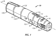
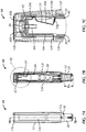
Fig. 1 is a perspective view of a training device in accordance with an exemplary embodiment of the present invention shown in a storage position; -
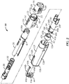
Fig. 2 is an exploded perspective view of the training device shown inFig. 1 ; -
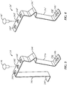
Fig. 3 is a perspective view of a leaf spring in accordance with an exemplary embodiment of the present invention; -
Fig. 4 is a perspective view of a leaf spring in accordance with another exemplary embodiment of the present invention; -
Fig. 5A is a rear elevational view of the training device ofFig. 1 shown in a storage position; -
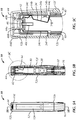
Fig. 5B is a side cross sectional view of the training device shown inFig. 5A taken along line A-A; -
Fig. 5C is an enlarged partial side cross sectional view of the training device shown within section B ofFig. 5B ; -
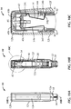
Fig. 6A is a rear elevational view of the training device ofFig. 1 shown in an armed position showing the safety and safety cap removed from the training device; -
Fig. 6B is a side cross sectional view of the training device shown inFig. 6A taken along line A-A; -
Fig. 6C is an enlarged partial side cross sectional view of the training device shown within section B ofFig. 6B ; -
Fig. 7A is a rear elevational view of the training device ofFig. 1 shown in an armed position; -
Fig. 7B is a side cross sectional view of the training device shown inFig. 7A taken along line A-A; -
Fig. 7C is an enlarged partial side cross sectional view of the training device shown within section B ofFig. 7B ; -
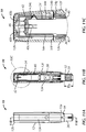
Fig. 8A is a rear elevational view of the training device ofFig. 1 shown in a partially retracted position; -
Fig. 8B is a side cross sectional view of the training device shown inFig. 8A taken along line A-A; -
Fig. 8C is an enlarged partial side cross sectional view of the training device shown within section B ofFig. 8B ; -
Fig. 9A is a rear elevational view of the training device ofFig. 1 shown in a retracted position; -
Fig. 9B is a side cross sectional view of the training device shown inFig. 9A taken along line A-A; -
Fig. 9C is an enlarged partial side cross sectional view of the training device shown within section B ofFig. 9B ; -
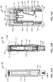
Fig. 10A is a rear elevational view of the training device ofFig. 1 shown in a partially extended position; -
Fig. 10B is a side cross sectional view of the training device shown inFig. 10A taken along line A-A; -
Fig. 10C is an enlarged partial side cross sectional view of the training device shown within section B ofFig. 10B ; -
Fig. 11A is a rear elevational view of the training device ofFig. 1 shown in a locked position; -
Fig. 11B is a side cross sectional view of the training device shown inFig. 11A taken along line A-A; -
Fig. 11C is an enlarged partial side cross sectional view of the training device shown within section B ofFig. 11B ; -
Fig. 12A is a rear elevational view of the training device ofFig. 1 shown in a reset storage position; -
Fig. 12B is a side cross sectional view of the training device shown inFig. 12A taken along line A-A; and -
Fig. 12C is an enlarged partial side cross sectional view of the training device shown within section B ofFig. 12B . - Referring to the drawings in detail, wherein like reference numerals indicate like elements throughout, there is shown in
Figs. 1-12C a training device, generally designated 10, in accordance with an exemplary embodiment of the present invention. -
Training device 10 is a training tool used to educate users on the proper orientation and operation of a corresponding auto-injector. The auto-injector of interest may require steps to arm the device, a certain amount of force to activate injection and/or make noises that a user may not be familiar with particularly before using an auto-injector for the first time.Training device 10 simulates the operation of an auto-injector so that a user can practice administering a medicament and get comfortable with how the auto-injector works without actually using the needle or dispensing the medicament. Unlike the auto-injector,training device 10 contains no medicament or needle assembly.Training device 10 may have the same look and feel as a particular auto-injector or a particular type of auto-injector so a user can become comfortable with using the auto-injector by practicing withtraining device 10.Training device 10 may be resettable to allow a user to repeat the simulated injection operation until the user becomes comfortable with its operation. Additionally,training device 10 may be used to train multiple individuals on the proper operation of an auto-injector. As such, family members can be educated on the proper operation of the auto-injector to assist the user. Furthermore,training device 10 may be used as a training aid in a hospital, clinic, or physician's office. -
Training device 10 may be used to train users on a variety of auto-injector configurations. In one embodiment,training device 10 is used to train users on use of Antares Pharma's VIBEX™ auto-injector. In one embodiment,training device 10 is used to train users on an auto-injector that injects methotrexate. In one embodiment,training device 10 is used to train users on an auto-injector that injects epinephrine. In one embodiment,training device 10, though resettable, is used to train users on single use auto-injectors. In other embodiment,training device 10 is used to train users on an auto-injector similar to those disclosed inU.S. Patent Application Publication Nos. 2012/0157965 and2011/0144594 andU.S. Provisional Patent No. 61/607,339 - Referring to
Figs. 1 and2 ,training device 10 includes ahousing 12 extending along longitudinal axis A and has adistal end 12a and aproximal end 12b. As used herein, movement along longitudinal axis A or in a direction generally parallel to longitudinal axis A is referred to as moving longitudinally, distally and/or proximally. It is noted that, in the context of this disclosure, the terms "distal" and "proximal" are used in reference to the position oftraining device 10 relative to a user of the injection device when merely held by a user. Accordingly, a point located distal to a second point would be further from the user (e.g., towards an injection end of training device 10) and vice versa. Also as used herein, movement is a direction perpendicular to longitudinal axis A is referred to as moving radially.Housing 12 couples, contains and/or protects the remaining components oftraining device 10.Housing 12 may be shaped and configured to be grasped by a single hand of a user. In one embodiment,housing 12 has a flattenedrear side 12e and a roundedfront side 12f. In such an embodiment, during use a user may grasptraining device 10 with their pinky proximatedistal end 12a and their thumb proximateproximal end 12b such the user's finger tips engage the flattenedside 12e and the user's palm wraps around roundedside 12f. The user may, however, grasphousing 12 in any radial orientation relative to their hand that feels comfortable. -
Housing 12 may be comprised of adistal portion 12c and aproximal portion 12d that are secured to one another during assembly by a fastener such as a snap fit. In other embodiments,distal portion 12c andproximal portion 12d ofhousing 12 are coupled to one another in any manner such a thread, adhesive, or press fit. In other embodiments,distal portion 12c andproximal portion 12d ofhousing 12 are integrally formed.Housing 12 may be transparent such that the user can see the interior components. In other embodiments,housing 12 is partially or entirely opaque to conceal one or more interior components.Housing 12 may includeindicia 14, such as for example an arrow with the phrase "needle end" to indicate which end oftraining device 10 is the simulated injection end. In other embodiments,indicia 14 may include trademarks, drug information and/or injection instructions such a list of steps for how to usetraining device 10. -
Training device 10 may include asafety cap 16 coupled todistal end 12a ofhousing 12. Certain auto-injectors may include a safety cap similar tosafety cap 16 to cover and protect the needle tip before use.Safety cap 16 may be provided so that a user practices with removing a similar safety cap from an auto-injector.Safety cap 16 may be coupled todistal end 12a of housing viathreads 18 such thatsafety cap 16 must be twisted relative tohousing 12 to removesafety cap 16 fromdistal end 12a ofhousing 12. In one embodiment,threads 18 extend partially around the perimeter ofdistal end 12a such that only a partial rotation ofsafety cap 16 relative tohousing 12 is required to removesafety cap 16 fromhousing 12. -
Safety cap 16 may be further coupled todistal end 12a ofhousing 12 via one or more fasteners such as a snap fit. In one embodiment, the fasteners include a projection 20 (seeFig. 6B ) extending radially inward fromsafety cap 16 that are configured to snap fit into corresponding grooves orapertures 22 in housing 12 (seeFig. 2 ). In one embodiment, the fasteners include projections 24 extending radially inward fromsafety cap 16 that are configured to engagecorresponding projections 30a extending radially outwardly from a needle guard 30 (seeFig. 6B ). One or more fastenerscoupling safety cap 16 andhousing 12 may be configured to preventsafety cap 16 from being removed fromhousing 12 solely by pullingsafety cap 16 distally fromhousing 12. In one embodiment, coupling andrecoupling safety cap 16 withhousing 12 creates an audible click to indicate that thesafety cap 16 has been secured or removed respectively. In one embodiment, twistingsafety cap 16 relative tohousing 12 allows forsafety cap 16 to be decoupled and removed fromhousing 12. In one embodiment, pullingsafety cap 16 distally fromhousing 12 without twistingsafety cap 16 relative tohousing 12 will not result insafety cap 16 decoupling fromhousing 12. The coupling betweensafety cap 16 andhousing 12 may include other configurations such as the inverse projection/aperture configuration shown in the drawings and/or other devices such as detents, latches or magnets. -
Safety cap 16 may includeindicia 26 such as for example an arrow with the word "twist" to indicate how to removesafety cap 16 fromhousing 12. In other embodiments,indicia 26 may include trademarks and/or injection instructions. -
Safety cap 16 may include one ormore grips 28 to help a user grasp andtwist safety cap 16 relative tohousing 12.Grips 28 may include one or more projections or textured areas that increase the friction between a user's fingers andsafety cap 16. In one embodiment,safety cap 16 includes twogrips 28 diametrically opposed from one another. -
Housing 12 may include one ormore viewing windows 8 configured to allow a user to see inside thehousing 12. A corresponding auto-injector may have similar windows to allow a user to see the level of medicament. One or more components such asneedle guard 30 may include correspondingapertures 6 that align withwindows 8.Windows 8 may be comprised of a transparent material. In one embodiment, a larger portion of thehousing 12 is comprised of a transparent material and a sticker or decal covers thehousing 12 leavingwindows 8 exposed. Twowindows 8 may be provided that are generally diametrically opposed from one another so that a user can see at least partially through thetraining device 10. In one embodiment,windows 8 are provided on the side surfaces. In other embodiments,windows 8 are provided on the top and bottom. - Referring to
Fig. 2 , in one embodiment,training device 10 includes aneedle guard 30 slidably received withdistal end 12a of thehousing 12. Certain auto-injectors may include a needle guard similar toneedle guard 30 to cover and protect a needle before and/or after use. In an auto-injector, the needle guard may extend over the needle before use, expose the needle in a retracted position during use and re-cover the needle after use. Such needle guards may require a predetermined amount of force to expose needle and then lock out over the needle following use to prevent or at least reduce accidental needle sticks.Training device 10 may include aneedle guard 30 similar to a needle guard of certain auto-injectors so that a user is familiar with its operation. - As will be described in further detail below, in some embodiments,
needle guard 30 is slidable from a first extended or storage position relative tohousing 12 prior to operation of training device 10 (seeFigs. 5A-7C ), to a retracted position relative tohousing 12 during operation of training device 10 (seeFigs. 8A-9C ), to a second extended or locked position relative tohousing 12 after operation of training device 10 (seeFigs. 10A-12C ) and resettable to the storage position (seeFigs. 12A-12C ). - Referring to
Fig. 2 ,training device 10 may include an actuation assembly coupled toneedle guard 30 configured to control movement ofneedle guard 30 relative tohousing 12. The actuation assembly may include a biasingmember 32 and alock 34. In one embodiment, biasingmember 32 is disposed betweenneedle guard 30 and lock 34 to urgeneedle guard 30 longitudinally away fromlock 34.Lock 34 may be coupled to alatch 40.Latch 40 may be coupled tohousing 12. In one embodiment, latch 40 does not move relative tohousing 12. Asleeve 38 may be provided between biasingmember 32 andlatch 40. In other embodiments, biasingmember 32 is coupled directly to latch 40. In one embodiment, biasingmember 32 is a helical compression spring. In other embodiments, biasingmember 32 is an elastomer, one or more springs of any configuration or a gas powered device. - Referring to
Fig. 2 , lock 34 may be controlled by atrigger 42. In one embodiment, trigger 42 is controlled by asafety 44 and theneedle guard 30. In one embodiment, trigger 42 is slidably coupled to a proximal end oflatch 40 to holdlock 34 at least partially withinlatch 40 in the storage mode and allowlock 34 to at least partially extend radially outwardly throughlatch 40 in the locked position.Trigger 42 may include a flattenedportion 42a. In one embodiment, trigger 42 includes diametrically opposed flattenedportions 42a. In one embodiment, flattenedportion 42a is configured to slidably engage aprojection 34c oflock 34. In one embodiment, trigger 42 is keyed to latch 40 to preventtrigger 42 from rotating relative to latch 40 and keep flattenedportion 42a aligned withprojection 34c oflock 34. In one embodiment, trigger 42 includes a notch 42c proximate the distal end of flattenedportion 42a. In one embodiment, notch 42c is shaped and configured to receive aprojection 34c oflock 34. In one embodiment, trigger 42 includes aprojection 42b that extends into aslot 40c inlatch 40. In one embodiment, trigger 42 includes two diametricallyopposed projections 42b that extends into diametricallyopposed slots 40c inlatch 40. In one embodiment, trigger 42 is generally symmetrical about a plane parallel with longitudinal axis - In one embodiment,
safety 44 includes at least oneprojection 44a that extends intohousing 12 to preventtrigger 42 from sliding proximally relative to latch 40 andlock 34. In one embodiment, at least oneprojection 44a is coupled to housing via a snap fit.Safety 44 may include aprojection 44c that engages withneedle guard 30. In one embodiment,projection 44c extends intohousing 12 and preventsneedle guard 30 from moving proximally towardproximal end 12b. In one embodiment,projection 44c extends from anarm 44b. In one embodiment,arm 44b extends into slot 12g inhousing 12 such thatarm 44b is generally flush with the outer contour ofhousing 12. In one embodiment,safety 44 includes atab 44d that extends distally fromsafety 44. In one embodiment,tab 44d is generally parallel witharm 44b. In one embodiment,tab 44d is diametrically opposed toarm 44b. In one embodiment,tab 44d includes one ormore grips 44e (seeFig. 6A ) to help auser push safety 44 fromhousing 12.Grips 44e may include one or more projections or textured areas that increase the friction between a user's fingers (such as a thumb) andtab 44d. - Referring to
Figs. 2 and3 , lock 34, in one embodiment, is a leaf spring.Lock 34 may be coupled to latch 40. In one embodiment, lock 34 is fastened to latch 40. In one embodiment, lock 34 is fastened to latch 40 by arivet 46.Lock 34 may include one ormore apertures 34d. In one embodiment, rivet 46 extends throughaperture 34d.Lock 34 may include at least oneadditional aperture 34d. In one embodiment, aprojection 40b extending fromlatch 40 may extend through one or moreadditional apertures 34d (seeFig. 5C ). In one embodiment, lock 34 includes threeapertures 34d. In one embodiment, one ormore apertures 34d on either side ofrivet 46 receive a projection fromlatch 40 to preventlock 34 from twisting relative to latch 40. In other embodiments, lock 34 is fastened to latch 40 by one or more of a screw, adhesive, spot weld and/or is coupled to latch 40 by the configuration of latch 40 (e.g., latch 40 may include a slot that lock 34 is slid through). - Referring to
Fig. 3 , lock 34 may include one or more cantilevers arms forming one or more leaf springs. In one embodiment, lock 34 has a generally flat proximal end and one or more distally extending arms forming one or more leaf springs.Lock 34 may include alock arm 34a. In one embodiment,lock arm 34a is coupled to latch 40 such thatlock arm 34a extends towarddistal end 12a.Lock arm 34a may include alock tab 34b. In one embodiment,lock tab 34b extends radially fromlock arm 34a.Lock tab 34b may include asupport 34g.Support 34g may be provided to locktab 34b to add rigidity and reduce or preventlock tab 34b from bending such as whenlock tab 34b is abutted byneedle guard 30 as discussed below. In one embodiment,support 34g is formed by an indent inlock tab 34b. In one embodiment,support 34g extends distally fromlock tab 34b. In other embodiments,support 34g may be formed by additional material or thickness added to locktab 34b. -
Lock arm 34a may include aprojection 34c proximal to locktab 34b.Projection 34c may be sloped at least on a side facing the proximal direction. In one embodiment,projection 34c is generally V-shaped. In on embodiment,projection 34c is tapered as it extends radially fromlock arm 34a. In one embodiment,projection 34c is formed by bends (e.g., three) inlock arm 34a. In other embodiments,projection 34c may be additional material or an attachment extending fromlock arm 34a.Lock 34 may include aresistance arm 34e. In one embodiment,resistance arm 34e is generally parallel withlock arm 34a.Resistance arm 34e may include aresistance tab 34f. In one embodiment,resistance tab 34f extends radially fromresistance arm 34e. In some embodiments, the angle betweenresistance tab 34f andresistance arm 34e may be set depending on the desired resistance for retractingneedle guard 30. In one embodiment,resistance tab 34f extends in the opposite direction thanlock tab 34b. In other embodiments, such as lock 34' shown inFig. 4 ,resistance arm 34e is omitted entirely. - Referring to
Fig. 2 , in one embodiment,projection 34c extends through and fromlatch 40. In one embodiment,lock tab 34b extends radially through and fromlatch 40. In one embodiment,lock tab 34b extends radially through anaperture 40a inlatch 40 such that a portion oflatch 40 extends overlock arm 34a in betweenlock tab 34b andprojection 34c. In one embodiment,resistance tab 34f extends radially through and fromlatch 40. - Referring to
Figs. 5A-5C ,training device 10 is shown in a storage position. The storage position, in some embodiments, is the initial position or the position that the user begins withtraining device 10. As shown inFigs. 5A and 5B ,safety cap 16 may be coupled todistal end 12a ofhousing 12 in the storage position.Safety cap 16 may be detached from and reattached tohousing 12 without impacting the storage position of the other components (e.g., without causing movement ofneedle guard 30 relative to housing 12). In other embodiments, removingsafety cap 16 may causetraining device 10 to enter an armed position. In the storage position, in one embodiment,projection 44c ofsafety 44 extends intohousing 12 and radially past a portion ofneedle guard 30 such thatneedle guard 30 abutsprojection 44c and is prevented from moving proximally relative tohousing 12. In the storage position, in one embodiment, trigger 42 is coupled to the proximal end oflatch 40 such that it extends overprojection 34c. In one embodiment, withprojection 34c pushed radially intolatch 40,lock arm 34a is biased further intolatch 40 such thatlock tab 34b is withinlatch 40 and out of the traveling path ofneedle guard 30. - Referring to
Figs. 6A-6C , in one embodiment, once the user is ready to usetraining device 10, the user will need to manipulatesafety 44 to placetraining device 10 into an armed position. In one embodiment, the armed position (seeFigs. 7A-7C ) is when thesafety projections 44a onsafety 44 no longer are in position to impede the movement oftrigger 42 proximally relative tohousing 12. In one embodiment, the armed position (seeFigs. 7A-7C ) is whenneedle guard 30 is moveable proximally relative tohousing 12. In one embodiment, the armed position is whentrigger 42 is moveable byneedle guard 30 relative to latch 40. In an auto-injector, the armed position corresponds to when the user can activate an injection. In one embodiment, removingsafety 44 andsafety cap 16 fromhousing 12, in either order, placestraining device 10 into the armed position. In other embodiments,safety 44 and/orsafety cap 16 remain coupled tohousing 12 in the armed position and movement or manipulation (e.g., twist or slide) ofsafety 44 and/orsafety cap 16 relative tohousing 12 causestraining device 10 to enter into the armed position. - In one embodiment, the user grasps
housing 12 with one hand and pushes proximally ongrips 44e ofsafety 44 with the thumb of the same hand to decouple safety fromhousing 12.Safety 44 may be coupled to the housing by one or more oftab 44d,projections 44a,arm 44b orprojection 44c. In one embodiment, the snap fit betweenprojections 44a andhousing 12 primarily couplessafety 44 tohousing 12. In one embodiment, removingprojections 44a from housing creates an audible click and/or a tactile feel in the user's hand to indicate thatsafety 44 has been removed andtraining device 10 is in the armed position. Oncesafety 44 has been removed, in one embodiment, user graspshousing 12 with one hand and graspssafety cap 16 with their other hand and separatessafety cap 16 relative tohousing 12 to removesafety cap 16 fromhousing 12. In one embodiment, the user twistssafety cap 16 relative tohousing 12 to removesafety cap 16 fromhousing 12. In one embodiment, removing safety cap fromhousing 12 exposes a portion ofneedle guard 30 extending fromdistal end 12a ofhousing 12. - Referring to
Figs. 7A-7C ,training device 10 is shown in the armed position. In the armed position,needle guard 30 may extend fromdistal end 12a a distance D1. In one embodiment, distance D1 simulates a distance that a needle guard would need to be retracted in an auto-injector to expose a needle during injection.Needle guard 30 may be restricted from moving proximally relative tohousing 12 byresistance tab 34f extending throughlatch 40. In one embodiment, when a user graspshousing 12 and pushes the distal end ofneedle guard 30 against an injection site,needle guard 30 moves proximally relative tohousing 12 untilneedle guard 30 abutsresistance tab 34f. In one embodiment,needle guard 30 moves a predetermined distance before abuttingresistance tab 34f. In other embodiments,needle guard 30 initially abutsresistance tab 34f in the armed position. In one embodiment, onceneedle guard 30 abutsresistance tab 34f a predetermined force is required forneedle guard 30 to move relative tohousing 12. In one embodiment, continued force onneedle guard 30 relative tohousing 12 caused byuser holding housing 12 and pushing the distal end of needle guard into their skin bendsresistance tab 34f and/orresistance arm 34e untilresistance arm 34e deflects radially inwardly intolatch 40 movingresistance tab 34f out of the path ofneedle guard 30. - Requiring a predetermined force in an auto-injector to move a needle guard relative to housing from the armed position to a retracted or injection position may help prevent accidental needle sticks. Accidental bumps against the distal end of the needle guard do not exert enough force to retract the needle guard and expose the needle. Requiring a predetermined force may also help to ensure that the needle is fully inserted during use. A user will not be able to slowly insert the needle and prematurely withdraw once they feel the needle piercing their skin due to the speed of injection once the predetermined force is overcome. In other embodiments,
resistance tab 34f and the additional predetermined force is omitted such as by using lock 34' as shown inFig. 4 . In one embodiment, only the resistance of biasingmember 32 resists movement ofneedle guard 30 relative tohousing 12. In one embodiment, continued force onneedle guard 30 relative tohousing 12 caused byuser holding housing 12 and pushing the distal end ofneedle guard 30 into their skin allowsneedle guard 30 to move a distance D1. - Referring to
Figs. 8A-8C ,training device 10 is shown asneedle guard 30 is being retracted intohousing 12. In one embodiment, movingneedle guard 30 proximally relative tohousing 12 simulates a needle being inserted in the user. As a needle guard in an auto-injector is retracted, the needle extends distally from the needle guard penetrating the skin of the user. - Referring to
Figs. 9A-9C ,training device 10 is shown in the retracted or injection position. In one embodiment, fully retractingneedle guard 30 proximally relative tohousing 12 simulates the injection step of an auto-injector. In one embodiment,needle guard 30 is substantially retracted intohousing 12 in the retracted position. In one embodiment, as the proximal end ofneedle guard 30 moves toward and abutstrigger 42,trigger 42 is slid proximally relative to latch 40. In one embodiment, a distal edge of trigger is slid proximally pastprojection 34c oflock 34. In one embodiment, a distal edge of trigger is slid proximally past the apex ofprojection 34c. - Referring to
Figs. 10A-10C ,training device 10 is shown as biasingmember 32 moves needleguard 30 distally relative tohousing 12 towards the second extended position. In one embodiment,needle guard 30 automatically moves distally relative tohousing 12 once the proximally facing force onneedle guard 30 is less than the biasing force of biasing member 32 (e.g., as a user pullshousing 12 from their skin). In one embodiment, the distal end ofneedle guard 30 remains in contact as the user pullshousing 12 away from their skin. In one embodiment, movement ofneedle guard 30 distally relative tohousing 12 toward the second extended position simulates removal of the auto-injector needle from the user. In one embodiment, movement ofneedle guard 30 distally relative tohousing 12 toward the second extended position allowsprojection 34c onlock 34 to extend radially from withinlatch 40. - Referring to
Figs. 11A-11C ,training device 10 is shown a locked position. In one embodiment,needle guard 30 is not retractable relative tohousing 12 in the locked position. In one embodiment, lockingneedle guard 30 relative tohousing 12 in the locked position simulates the auto-injector after use where the needle guard covers the needle tip and prevents reuse. In one embodiment,needle guard 30 extends fromdistal end 12a ofhousing 12 a distance D2. In one embodiment, distance D2 is equal to distance D1 (seeFig. 7B ). In other embodiments, distance D2 may be greater or less than distance D1. In one embodiment, onceneedle guard 30 extends distally longitudinallypast lock tab 34b,lock arm 34a is radially biased by the spring force oflock arm 34a towards its natural shape such thatlock tab 34b extends throughlatch 40 and into the sliding path ofneedle guard 30. In one embodiment,lock tab 34b preventsneedle guard 30 from retracting or moving proximally relative tohousing 12 toward the retracted position. - Referring to
Figs. 12A-12C ,training device 10 is shown in a reset storage position.Safety 44 may be actuated to returntraining device 10 to the initial or storage position for subsequent training. Though certain auto-injectors may not be reusable,training device 10 may be resettable and used multiple times. In one embodiment,safety 44 is recoupled tohousing 12 to movetraining device 10 from the locked position to the storage position. In one embodiment,projections 44a extend through housing,abut trigger 42 and slide trigger 42 overlatch 40. In one embodiment, astrigger 42 slides relative to latch 40,projection 34c oflock 34 extends through notch 42c (seeFig. 2 ) oftrigger 42. In one embodiment, astrigger 42 slides further relative to latch 40, flattenedportion 42a oftrigger 42 slides overprojection 34c to radiallybias lock arm 34a inwardly intolatch 40 and movelock tab 34b intolatch 40 and out of the path ofneedle guard 30 to resettraining device 10. In one embodiment, trigger 42 alone moves locktab 34b intolatch 40. In other embodiments,projection 44c ofsafety 44 assists in movinglock tab 34b intolatch 40. In one embodiment, aftersafety 44 is coupled tohousing 12 andtraining device 10 is reset to the storage position,safety cap 16 may be recoupled todistal end 12a of housing 12 (seeFigs. 5A-5C ). In other embodiments,training device 10 is used again withoutrecoupling safety cap 16. - It will be appreciated by those skilled in the art that changes could be made to the exemplary embodiments shown and described above without departing from the inventive concept defined in the claims. It is understood, therefore, that this invention is not limited to the exemplary embodiments shown and described, but it is intended to cover modifications within the scope of the present invention as defined by the claims. For example, specific features of the exemplary embodiments may or may not be part of the claimed invention and various features of the disclosed embodiments may be combined. Unless specifically set forth herein, the terms "a", "an" and "the" are not limited to one element but instead should be read as meaning "at least one".
Claims (15)
- A training device for training a user on the operation of an auto-injector that dispenses a medicament, the training device comprising:a housing (12) having a distal end (12a) and a proximal end (12b);a needle guard (30) slidably received with the distal end (12a) of the housing (12) the needle guard (30) slidable from a first extended position relative to the housing (12) prior to operation of the training device, to a retracted position relative to the housing (18) during operation of the training device, and to a second extended position relative to the housing (18) after operation of the training device;an actuation assembly coupled to the needle guard (30), the actuation assembly having a biasing member (32) and a lock (34), the actuation assembly controlling the movement of the needle guard (30) from the retracted position to the second extended position, the lock (34) locking the needle guard (30) in the second extended position in a locked position; anda safety (44) proximate the proximal end (12b) of the housing (18),characterized in thatthe safety (44) prevents movement of the needle guard (30) from the first extended position to the retracted position in a storage position, the needle guard (30) is moveable into the retracted position with the safety (44) in an armed position, and the safety (44) resets the lock (34) upon returning the safety (44) to the storage position.
- The training device of claim 1, wherein the lock (34) is a leaf spring.
- The training device of claim 2, wherein the leaf spring includes a first leg and a second leg, or a single leg.
- The training device of claim 3, wherein the first leg of the first and second legs includes a radially extending lock tab (34b) that restricts movement of needle guard (30) relative to housing (12) in the second extended position, and the second leg includes a radially extending resistance tab (34f) that provides a resistance force that must be overcome to move the needle guard (30) to the retracted position.
- The training device of claim 4, wherein the first leg includes a projection proximal to the lock tab (34b).
- The training device of claim 3, wherein the first leg includes a radially extending lock tab (34b) that restricts movement of needle guard (30) relative to housing (12) in the second extended position.
- The training device of claim 2, wherein the leaf spring is attached to the actuation assembly by a fastening means and wherein the fastening means is possibly a rivet (46).
- The training device of any of the preceding claims, wherein the actuation assembly includes a trigger (42), the trigger (42) retaining the lock (34) in the storage position, the needle guard (30) sliding the trigger (42) off of the lock (34) when the needle guard (30) is moved from the first extended position to the retracted position.
- The training device of claim 8, wherein the safety (44) slides the trigger (42) back over the lock (34) between the locked position and the storage position.
- The training device of any of the preceding claims, wherein the safety (44) is removably coupled to the housing (12) removing the safety (44) from the housing (12) allows the user to urge the needle guard (30) into the retracted position in the armed position, and reattaching the safety (44) to the housing (12) resets the lock (34) to the storage position.
- The training device of any of the preceding claims, wherein the needle guard (30) extends from the distal end (12a) of the housing (12) in the first extended position a distance equal to a distance the needle guard (30) extends from the distal end (12a) of the housing (18) in the second extended position.
- The training device of any of the preceding claims, wherein a predetermined force, in addition to the force of the biasing member (32), must be exerted on the needle guard (30) relative to the housing (12) to move the needle guard (30) out of the first extended position.
- The training device of any of the preceding claims, wherein a first projection of the safety (44) extends into the proximal end (12b) of the housing (12) and a second projection of the safety (44) extends into a sidewall of the housing (12) in the storage position.
- The training device of any of the preceding claims, wherein the training device does not include a needle and/or does not contain medicament.
- The training device of any of the preceding claims, wherein the training device is not capable of injecting medicament.
Applications Claiming Priority (2)
| Application Number | Priority Date | Filing Date | Title |
|---|---|---|---|
| US201361778937P | 2013-03-13 | 2013-03-13 | |
| PCT/US2014/023883 WO2014164948A1 (en) | 2013-03-13 | 2014-03-12 | Injector training device |
Publications (3)
| Publication Number | Publication Date |
|---|---|
| EP2968772A1 EP2968772A1 (en) | 2016-01-20 |
| EP2968772A4 EP2968772A4 (en) | 2016-08-24 |
| EP2968772B1 true EP2968772B1 (en) | 2018-09-05 |
Family
ID=51659018
Family Applications (1)
| Application Number | Title | Priority Date | Filing Date |
|---|---|---|---|
| EP14778736.0A Active EP2968772B1 (en) | 2013-03-13 | 2014-03-12 | Injector training device |
Country Status (6)
| Country | Link |
|---|---|
| US (3) | US10013895B2 (en) |
| EP (1) | EP2968772B1 (en) |
| JP (2) | JP6190034B2 (en) |
| CA (1) | CA2903498C (en) |
| ES (1) | ES2691194T3 (en) |
| WO (1) | WO2014164948A1 (en) |
Families Citing this family (17)
| Publication number | Priority date | Publication date | Assignee | Title |
|---|---|---|---|---|
| EP2784766A1 (en) * | 2013-03-28 | 2014-10-01 | F. Hoffmann-La Roche AG | Training device for medicine injection devices and reset device for resetting such a training device |
| AU2015208397B2 (en) * | 2014-01-21 | 2017-08-10 | Shl Medical Ag | Injector training device |
| WO2016078870A1 (en) * | 2014-11-20 | 2016-05-26 | Carebay Europe Ltd | Automatic injection training device |
| EP3251109B1 (en) | 2015-01-26 | 2023-09-20 | Noble International, Inc. | Injection simulation device and method |
| CH709126A2 (en) | 2015-05-07 | 2015-07-15 | Tecpharma Licensing Ag | Training device for a user to use an auto-injector training. |
| CN108352131B (en) | 2015-08-11 | 2021-09-03 | 诺博国际公司 | Prefilled syringe training device with releasable needle locking protector |
| US10842946B2 (en) * | 2015-11-27 | 2020-11-24 | Sanofi-Aventis Deutschland Gmbh | Injection device |
| US10089902B2 (en) * | 2016-05-23 | 2018-10-02 | Noble International, Inc. | Resettable locking shield-activated auto injector training device |
| US10086133B2 (en) | 2016-05-26 | 2018-10-02 | Medtronic Minimed, Inc. | Systems for set connector assembly with lock |
| US9968737B2 (en) * | 2016-05-26 | 2018-05-15 | Medtronic Minimed, Inc. | Systems for set connector assembly with lock |
| US10086134B2 (en) * | 2016-05-26 | 2018-10-02 | Medtronic Minimed, Inc. | Systems for set connector assembly with lock |
| WO2017211531A1 (en) | 2016-06-08 | 2017-12-14 | Carebay Europe Ltd. | Administration mechanism for a medicament delivery training device |
| EP3580738B1 (en) | 2017-02-07 | 2023-04-12 | Noble International, Inc. | Injection simulation device and method |
| GB201715237D0 (en) * | 2017-09-21 | 2017-11-08 | Shore Product Group Ltd | Training device |
| WO2019217789A1 (en) | 2018-05-11 | 2019-11-14 | The Penn State Research Foundation | Low cost haptic force medical instrument insertion simulator |
| US20210268198A1 (en) * | 2018-06-28 | 2021-09-02 | Noble International, Llc | Resettable lateral actuation member-activated autoinjector training device |
| GB2577693B (en) | 2018-10-01 | 2022-06-22 | Janssen Pharmaceuticals Inc | Reset connector for an injection device and an injection device trainer |
Family Cites Families (16)
| Publication number | Priority date | Publication date | Assignee | Title |
|---|---|---|---|---|
| US4986816A (en) * | 1989-01-18 | 1991-01-22 | On-Gard Systems, Inc. | Needle unsheathing, resheathing and handling apparatus |
| EP0423864A1 (en) * | 1989-10-16 | 1991-04-24 | Duphar International Research B.V | Training device for an automatic injector |
| EP0425003A1 (en) * | 1989-10-24 | 1991-05-02 | Duphar International Research B.V | Training device for an automatic injector |
| US5195983A (en) * | 1991-08-27 | 1993-03-23 | Penta Associates | Syringe guard and disposal system |
| US5567160A (en) * | 1995-10-26 | 1996-10-22 | Survival Technology, Inc. | Autoinjector training device |
| US6969372B1 (en) * | 2003-01-07 | 2005-11-29 | Halseth Thor R | Automatic retraction Huber needle safety enclosure |
| US9022980B2 (en) * | 2005-02-01 | 2015-05-05 | Kaleo, Inc. | Medical injector simulation device |
| US7682155B2 (en) * | 2005-11-03 | 2010-03-23 | Meridian Medical Technologies, Inc. | Training device for an automatic injector |
| US20080249477A1 (en) * | 2007-04-05 | 2008-10-09 | West Pharmaceutical Services, Inc. | Pen injector having a needle shield |
| WO2009040602A1 (en) * | 2007-09-25 | 2009-04-02 | Becton Dickinson France | Autoinject0r with deactivating means moveable by a safety shield |
| WO2010035060A1 (en) * | 2008-09-29 | 2010-04-01 | Becton Dickinson France | Automatic injection device |
| WO2012023938A1 (en) * | 2010-08-19 | 2012-02-23 | West Pharmaceutical Services, Inc. | Rigid needle shield |
| WO2012138285A1 (en) * | 2011-04-05 | 2012-10-11 | Shl Group Ab | Medicament delivery device comprising a locking mechanism having a lever |
| CA2865236A1 (en) * | 2012-03-02 | 2013-09-06 | Abbvie Inc. | Automatic injection training device |
| JP6047238B2 (en) * | 2012-10-11 | 2016-12-21 | ケアベイ・ヨーロッパ・リミテッドCarebay Europe Limited | Automatic injection training device |
| US20140276413A1 (en) * | 2013-03-15 | 2014-09-18 | Jeff Baker | Medicament delivery and simulation system with a removable disposable container for medicament and a rotatable actuation component |
-
2014
- 2014-03-12 WO PCT/US2014/023883 patent/WO2014164948A1/en active Application Filing
- 2014-03-12 US US14/774,106 patent/US10013895B2/en active Active
- 2014-03-12 JP JP2016501375A patent/JP6190034B2/en active Active
- 2014-03-12 CA CA2903498A patent/CA2903498C/en active Active
- 2014-03-12 EP EP14778736.0A patent/EP2968772B1/en active Active
- 2014-03-12 ES ES14778736.0T patent/ES2691194T3/en active Active
-
2017
- 2017-08-01 JP JP2017148943A patent/JP6456440B2/en not_active Expired - Fee Related
-
2018
- 2018-06-25 US US16/017,418 patent/US10490104B2/en active Active
-
2019
- 2019-10-29 US US16/666,825 patent/US11176847B2/en active Active
Non-Patent Citations (1)
| Title |
|---|
| None * |
Also Published As
| Publication number | Publication date |
|---|---|
| US11176847B2 (en) | 2021-11-16 |
| JP2017215604A (en) | 2017-12-07 |
| JP2016517544A (en) | 2016-06-16 |
| US10490104B2 (en) | 2019-11-26 |
| JP6190034B2 (en) | 2017-08-30 |
| EP2968772A4 (en) | 2016-08-24 |
| US20200066185A1 (en) | 2020-02-27 |
| US20160049098A1 (en) | 2016-02-18 |
| CA2903498C (en) | 2018-09-11 |
| EP2968772A1 (en) | 2016-01-20 |
| US10013895B2 (en) | 2018-07-03 |
| ES2691194T3 (en) | 2018-11-26 |
| US20180308392A1 (en) | 2018-10-25 |
| CA2903498A1 (en) | 2014-10-09 |
| JP6456440B2 (en) | 2019-01-23 |
| WO2014164948A1 (en) | 2014-10-09 |
Similar Documents
| Publication | Publication Date | Title |
|---|---|---|
| US11176847B2 (en) | Injector training device | |
| US7682155B2 (en) | Training device for an automatic injector | |
| CN106913938B (en) | Medicament delivery device | |
| JP4864863B2 (en) | Automatic syringe | |
| EP1919541B1 (en) | Needle shroud assembly | |
| US20050222539A1 (en) | Automatic injection device | |
| CN109803699B (en) | Medicament delivery device with a cap assembly | |
| JP6359774B2 (en) | Dose setting mechanism and drug delivery device including dose setting mechanism | |
| BR112014005272B1 (en) | rechargeable autoinjector for adrenaline injection | |
| JP2018515150A (en) | Needle assembly having a needle shroud and a movable needle support | |
| CN107635603B (en) | Drive mechanism for an autoinjector | |
| US20190143041A1 (en) | Injection devices | |
| EP2560711B1 (en) | Medicament delivery device | |
| US20150305660A1 (en) | Puncture instrument, puncture needle cartridge mounted in puncture instrument, and method for using puncture instrument and puncture needle cartridge | |
| GB2549964A (en) | Medicament delivery devices | |
| AU2013219152A1 (en) | Training device for an automatic injector |
Legal Events
| Date | Code | Title | Description |
|---|---|---|---|
| PUAI | Public reference made under article 153(3) epc to a published international application that has entered the european phase |
Free format text: ORIGINAL CODE: 0009012 |
|
| 17P | Request for examination filed |
Effective date: 20151005 |
|
| AK | Designated contracting states |
Kind code of ref document: A1 Designated state(s): AL AT BE BG CH CY CZ DE DK EE ES FI FR GB GR HR HU IE IS IT LI LT LU LV MC MK MT NL NO PL PT RO RS SE SI SK SM TR |
|
| AX | Request for extension of the european patent |
Extension state: BA ME |
|
| DAX | Request for extension of the european patent (deleted) | ||
| A4 | Supplementary search report drawn up and despatched |
Effective date: 20160726 |
|
| RIC1 | Information provided on ipc code assigned before grant |
Ipc: G06G 3/10 20060101ALI20160720BHEP Ipc: A61M 5/20 20060101AFI20160720BHEP Ipc: G09B 23/28 20060101ALI20160720BHEP |
|
| RAP1 | Party data changed (applicant data changed or rights of an application transferred) |
Owner name: ANTARES PHARMA, INC. |
|
| GRAP | Despatch of communication of intention to grant a patent |
Free format text: ORIGINAL CODE: EPIDOSNIGR1 |
|
| STAA | Information on the status of an ep patent application or granted ep patent |
Free format text: STATUS: GRANT OF PATENT IS INTENDED |
|
| INTG | Intention to grant announced |
Effective date: 20180131 |
|
| GRAS | Grant fee paid |
Free format text: ORIGINAL CODE: EPIDOSNIGR3 |
|
| GRAA | (expected) grant |
Free format text: ORIGINAL CODE: 0009210 |
|
| STAA | Information on the status of an ep patent application or granted ep patent |
Free format text: STATUS: THE PATENT HAS BEEN GRANTED |
|
| AK | Designated contracting states |
Kind code of ref document: B1 Designated state(s): AL AT BE BG CH CY CZ DE DK EE ES FI FR GB GR HR HU IE IS IT LI LT LU LV MC MK MT NL NO PL PT RO RS SE SI SK SM TR |
|
| REG | Reference to a national code |
Ref country code: GB Ref legal event code: FG4D |
|
| REG | Reference to a national code |
Ref country code: CH Ref legal event code: EP |
|
| REG | Reference to a national code |
Ref country code: AT Ref legal event code: REF Ref document number: 1037126 Country of ref document: AT Kind code of ref document: T Effective date: 20180915 |
|
| REG | Reference to a national code |
Ref country code: IE Ref legal event code: FG4D |
|
| REG | Reference to a national code |
Ref country code: DE Ref legal event code: R096 Ref document number: 602014031862 Country of ref document: DE |
|
| REG | Reference to a national code |
Ref country code: CH Ref legal event code: NV Representative=s name: KIRKER AND CIE S.A., CH |
|
| REG | Reference to a national code |
Ref country code: ES Ref legal event code: FG2A Ref document number: 2691194 Country of ref document: ES Kind code of ref document: T3 Effective date: 20181126 |
|
| REG | Reference to a national code |
Ref country code: NL Ref legal event code: MP Effective date: 20180905 |
|
| REG | Reference to a national code |
Ref country code: LT Ref legal event code: MG4D |
|
| PG25 | Lapsed in a contracting state [announced via postgrant information from national office to epo] |
Ref country code: NO Free format text: LAPSE BECAUSE OF FAILURE TO SUBMIT A TRANSLATION OF THE DESCRIPTION OR TO PAY THE FEE WITHIN THE PRESCRIBED TIME-LIMIT Effective date: 20181205 Ref country code: BG Free format text: LAPSE BECAUSE OF FAILURE TO SUBMIT A TRANSLATION OF THE DESCRIPTION OR TO PAY THE FEE WITHIN THE PRESCRIBED TIME-LIMIT Effective date: 20181205 Ref country code: SE Free format text: LAPSE BECAUSE OF FAILURE TO SUBMIT A TRANSLATION OF THE DESCRIPTION OR TO PAY THE FEE WITHIN THE PRESCRIBED TIME-LIMIT Effective date: 20180905 Ref country code: GR Free format text: LAPSE BECAUSE OF FAILURE TO SUBMIT A TRANSLATION OF THE DESCRIPTION OR TO PAY THE FEE WITHIN THE PRESCRIBED TIME-LIMIT Effective date: 20181206 Ref country code: RS Free format text: LAPSE BECAUSE OF FAILURE TO SUBMIT A TRANSLATION OF THE DESCRIPTION OR TO PAY THE FEE WITHIN THE PRESCRIBED TIME-LIMIT Effective date: 20180905 Ref country code: FI Free format text: LAPSE BECAUSE OF FAILURE TO SUBMIT A TRANSLATION OF THE DESCRIPTION OR TO PAY THE FEE WITHIN THE PRESCRIBED TIME-LIMIT Effective date: 20180905 Ref country code: LT Free format text: LAPSE BECAUSE OF FAILURE TO SUBMIT A TRANSLATION OF THE DESCRIPTION OR TO PAY THE FEE WITHIN THE PRESCRIBED TIME-LIMIT Effective date: 20180905 |
|
| REG | Reference to a national code |
Ref country code: AT Ref legal event code: MK05 Ref document number: 1037126 Country of ref document: AT Kind code of ref document: T Effective date: 20180905 |
|
| PG25 | Lapsed in a contracting state [announced via postgrant information from national office to epo] |
Ref country code: LV Free format text: LAPSE BECAUSE OF FAILURE TO SUBMIT A TRANSLATION OF THE DESCRIPTION OR TO PAY THE FEE WITHIN THE PRESCRIBED TIME-LIMIT Effective date: 20180905 Ref country code: AL Free format text: LAPSE BECAUSE OF FAILURE TO SUBMIT A TRANSLATION OF THE DESCRIPTION OR TO PAY THE FEE WITHIN THE PRESCRIBED TIME-LIMIT Effective date: 20180905 Ref country code: HR Free format text: LAPSE BECAUSE OF FAILURE TO SUBMIT A TRANSLATION OF THE DESCRIPTION OR TO PAY THE FEE WITHIN THE PRESCRIBED TIME-LIMIT Effective date: 20180905 |
|
| PG25 | Lapsed in a contracting state [announced via postgrant information from national office to epo] |
Ref country code: PL Free format text: LAPSE BECAUSE OF FAILURE TO SUBMIT A TRANSLATION OF THE DESCRIPTION OR TO PAY THE FEE WITHIN THE PRESCRIBED TIME-LIMIT Effective date: 20180905 Ref country code: IS Free format text: LAPSE BECAUSE OF FAILURE TO SUBMIT A TRANSLATION OF THE DESCRIPTION OR TO PAY THE FEE WITHIN THE PRESCRIBED TIME-LIMIT Effective date: 20190105 Ref country code: CZ Free format text: LAPSE BECAUSE OF FAILURE TO SUBMIT A TRANSLATION OF THE DESCRIPTION OR TO PAY THE FEE WITHIN THE PRESCRIBED TIME-LIMIT Effective date: 20180905 Ref country code: AT Free format text: LAPSE BECAUSE OF FAILURE TO SUBMIT A TRANSLATION OF THE DESCRIPTION OR TO PAY THE FEE WITHIN THE PRESCRIBED TIME-LIMIT Effective date: 20180905 Ref country code: NL Free format text: LAPSE BECAUSE OF FAILURE TO SUBMIT A TRANSLATION OF THE DESCRIPTION OR TO PAY THE FEE WITHIN THE PRESCRIBED TIME-LIMIT Effective date: 20180905 Ref country code: RO Free format text: LAPSE BECAUSE OF FAILURE TO SUBMIT A TRANSLATION OF THE DESCRIPTION OR TO PAY THE FEE WITHIN THE PRESCRIBED TIME-LIMIT Effective date: 20180905 Ref country code: EE Free format text: LAPSE BECAUSE OF FAILURE TO SUBMIT A TRANSLATION OF THE DESCRIPTION OR TO PAY THE FEE WITHIN THE PRESCRIBED TIME-LIMIT Effective date: 20180905 |
|
| PG25 | Lapsed in a contracting state [announced via postgrant information from national office to epo] |
Ref country code: SM Free format text: LAPSE BECAUSE OF FAILURE TO SUBMIT A TRANSLATION OF THE DESCRIPTION OR TO PAY THE FEE WITHIN THE PRESCRIBED TIME-LIMIT Effective date: 20180905 Ref country code: PT Free format text: LAPSE BECAUSE OF FAILURE TO SUBMIT A TRANSLATION OF THE DESCRIPTION OR TO PAY THE FEE WITHIN THE PRESCRIBED TIME-LIMIT Effective date: 20190105 Ref country code: SK Free format text: LAPSE BECAUSE OF FAILURE TO SUBMIT A TRANSLATION OF THE DESCRIPTION OR TO PAY THE FEE WITHIN THE PRESCRIBED TIME-LIMIT Effective date: 20180905 |
|
| REG | Reference to a national code |
Ref country code: DE Ref legal event code: R097 Ref document number: 602014031862 Country of ref document: DE |
|
| PLBE | No opposition filed within time limit |
Free format text: ORIGINAL CODE: 0009261 |
|
| STAA | Information on the status of an ep patent application or granted ep patent |
Free format text: STATUS: NO OPPOSITION FILED WITHIN TIME LIMIT |
|
| PG25 | Lapsed in a contracting state [announced via postgrant information from national office to epo] |
Ref country code: DK Free format text: LAPSE BECAUSE OF FAILURE TO SUBMIT A TRANSLATION OF THE DESCRIPTION OR TO PAY THE FEE WITHIN THE PRESCRIBED TIME-LIMIT Effective date: 20180905 |
|
| 26N | No opposition filed |
Effective date: 20190606 |
|
| PG25 | Lapsed in a contracting state [announced via postgrant information from national office to epo] |
Ref country code: SI Free format text: LAPSE BECAUSE OF FAILURE TO SUBMIT A TRANSLATION OF THE DESCRIPTION OR TO PAY THE FEE WITHIN THE PRESCRIBED TIME-LIMIT Effective date: 20180905 |
|
| PG25 | Lapsed in a contracting state [announced via postgrant information from national office to epo] |
Ref country code: MC Free format text: LAPSE BECAUSE OF FAILURE TO SUBMIT A TRANSLATION OF THE DESCRIPTION OR TO PAY THE FEE WITHIN THE PRESCRIBED TIME-LIMIT Effective date: 20180905 |
|
| PG25 | Lapsed in a contracting state [announced via postgrant information from national office to epo] |
Ref country code: LU Free format text: LAPSE BECAUSE OF NON-PAYMENT OF DUE FEES Effective date: 20190312 |
|
| REG | Reference to a national code |
Ref country code: BE Ref legal event code: MM Effective date: 20190331 |
|
| PG25 | Lapsed in a contracting state [announced via postgrant information from national office to epo] |
Ref country code: IE Free format text: LAPSE BECAUSE OF NON-PAYMENT OF DUE FEES Effective date: 20190312 |
|
| PG25 | Lapsed in a contracting state [announced via postgrant information from national office to epo] |
Ref country code: BE Free format text: LAPSE BECAUSE OF NON-PAYMENT OF DUE FEES Effective date: 20190331 |
|
| PG25 | Lapsed in a contracting state [announced via postgrant information from national office to epo] |
Ref country code: TR Free format text: LAPSE BECAUSE OF FAILURE TO SUBMIT A TRANSLATION OF THE DESCRIPTION OR TO PAY THE FEE WITHIN THE PRESCRIBED TIME-LIMIT Effective date: 20180905 |
|
| PG25 | Lapsed in a contracting state [announced via postgrant information from national office to epo] |
Ref country code: MT Free format text: LAPSE BECAUSE OF NON-PAYMENT OF DUE FEES Effective date: 20190312 |
|
| PG25 | Lapsed in a contracting state [announced via postgrant information from national office to epo] |
Ref country code: CY Free format text: LAPSE BECAUSE OF FAILURE TO SUBMIT A TRANSLATION OF THE DESCRIPTION OR TO PAY THE FEE WITHIN THE PRESCRIBED TIME-LIMIT Effective date: 20180905 |
|
| PG25 | Lapsed in a contracting state [announced via postgrant information from national office to epo] |
Ref country code: HU Free format text: LAPSE BECAUSE OF FAILURE TO SUBMIT A TRANSLATION OF THE DESCRIPTION OR TO PAY THE FEE WITHIN THE PRESCRIBED TIME-LIMIT; INVALID AB INITIO Effective date: 20140312 |
|
| PG25 | Lapsed in a contracting state [announced via postgrant information from national office to epo] |
Ref country code: MK Free format text: LAPSE BECAUSE OF FAILURE TO SUBMIT A TRANSLATION OF THE DESCRIPTION OR TO PAY THE FEE WITHIN THE PRESCRIBED TIME-LIMIT Effective date: 20180905 |
|
| PGFP | Annual fee paid to national office [announced via postgrant information from national office to epo] |
Ref country code: FR Payment date: 20230327 Year of fee payment: 10 |
|
| PGFP | Annual fee paid to national office [announced via postgrant information from national office to epo] |
Ref country code: IT Payment date: 20230321 Year of fee payment: 10 Ref country code: GB Payment date: 20230327 Year of fee payment: 10 Ref country code: DE Payment date: 20230329 Year of fee payment: 10 |
|
| P01 | Opt-out of the competence of the unified patent court (upc) registered |
Effective date: 20230516 |
|
| PGFP | Annual fee paid to national office [announced via postgrant information from national office to epo] |
Ref country code: ES Payment date: 20230403 Year of fee payment: 10 Ref country code: CH Payment date: 20230402 Year of fee payment: 10 |
|
| PGFP | Annual fee paid to national office [announced via postgrant information from national office to epo] |
Ref country code: DE Payment date: 20240327 Year of fee payment: 11 Ref country code: GB Payment date: 20240327 Year of fee payment: 11 |