EP2952929B1 - Laser scanner system - Google Patents
Laser scanner system Download PDFInfo
- Publication number
- EP2952929B1 EP2952929B1 EP15170355.0A EP15170355A EP2952929B1 EP 2952929 B1 EP2952929 B1 EP 2952929B1 EP 15170355 A EP15170355 A EP 15170355A EP 2952929 B1 EP2952929 B1 EP 2952929B1
- Authority
- EP
- European Patent Office
- Prior art keywords
- light
- laser scanner
- laser
- distance measuring
- selection signal
- Prior art date
- Legal status (The legal status is an assumption and is not a legal conclusion. Google has not performed a legal analysis and makes no representation as to the accuracy of the status listed.)
- Active
Links
Images

Classifications
-
- G—PHYSICS
- G01—MEASURING; TESTING
- G01S—RADIO DIRECTION-FINDING; RADIO NAVIGATION; DETERMINING DISTANCE OR VELOCITY BY USE OF RADIO WAVES; LOCATING OR PRESENCE-DETECTING BY USE OF THE REFLECTION OR RERADIATION OF RADIO WAVES; ANALOGOUS ARRANGEMENTS USING OTHER WAVES
- G01S17/00—Systems using the reflection or reradiation of electromagnetic waves other than radio waves, e.g. lidar systems
- G01S17/87—Combinations of systems using electromagnetic waves other than radio waves
-
- G—PHYSICS
- G01—MEASURING; TESTING
- G01S—RADIO DIRECTION-FINDING; RADIO NAVIGATION; DETERMINING DISTANCE OR VELOCITY BY USE OF RADIO WAVES; LOCATING OR PRESENCE-DETECTING BY USE OF THE REFLECTION OR RERADIATION OF RADIO WAVES; ANALOGOUS ARRANGEMENTS USING OTHER WAVES
- G01S17/00—Systems using the reflection or reradiation of electromagnetic waves other than radio waves, e.g. lidar systems
- G01S17/02—Systems using the reflection of electromagnetic waves other than radio waves
- G01S17/06—Systems determining position data of a target
- G01S17/42—Simultaneous measurement of distance and other co-ordinates
-
- G—PHYSICS
- G01—MEASURING; TESTING
- G01S—RADIO DIRECTION-FINDING; RADIO NAVIGATION; DETERMINING DISTANCE OR VELOCITY BY USE OF RADIO WAVES; LOCATING OR PRESENCE-DETECTING BY USE OF THE REFLECTION OR RERADIATION OF RADIO WAVES; ANALOGOUS ARRANGEMENTS USING OTHER WAVES
- G01S17/00—Systems using the reflection or reradiation of electromagnetic waves other than radio waves, e.g. lidar systems
- G01S17/88—Lidar systems specially adapted for specific applications
- G01S17/89—Lidar systems specially adapted for specific applications for mapping or imaging
-
- G—PHYSICS
- G01—MEASURING; TESTING
- G01S—RADIO DIRECTION-FINDING; RADIO NAVIGATION; DETERMINING DISTANCE OR VELOCITY BY USE OF RADIO WAVES; LOCATING OR PRESENCE-DETECTING BY USE OF THE REFLECTION OR RERADIATION OF RADIO WAVES; ANALOGOUS ARRANGEMENTS USING OTHER WAVES
- G01S7/00—Details of systems according to groups G01S13/00, G01S15/00, G01S17/00
- G01S7/48—Details of systems according to groups G01S13/00, G01S15/00, G01S17/00 of systems according to group G01S17/00
- G01S7/481—Constructional features, e.g. arrangements of optical elements
- G01S7/4817—Constructional features, e.g. arrangements of optical elements relating to scanning
Definitions
- the present invention relates to a laser scanner system, which has a plurality of scanners and acquires point cloud data in a wide range.
- a method in which laser scanners are installed on a movable object such as an automobile and acquire point cloud data of a predetermined range along a moving line.
- a point cloud data thus acquired is used as a map data of a navigation system or is used for measuring a shape of building structure or is used as a data for judging a condition of a road surface.
- the laser scanners there is a laser scanner of TOF (TIME OF FLIGHT) type.
- the laser scanner emits a laser beam (a distance measuring light) by pulsed emitting, measures a distance of a projecting point (a measuring point) per each pulsed light by receiving a reflected light and based on a time required for a round trip of the pulsed light, and further, by scanning the laser beam within a range as required, point cloud data are acquired.
- a laser scanner is installed on a movable object, e.g. an automobile
- the laser scanner is installed at a part where a visual field from the automobile is opened, e.g. one laser scanner is installed on a ceiling of the automobile, the emitted laser beam is scanned in a direction crossing a moving line, and the point cloud data within a predetermined range along the moving line is acquired.
- the publication, " Stanley: The Robot that Won the DARPA Grand Challenge", by S. Thrun et al. in Journal of Field Robotics, vol. 23, no. 9, p. 661 - 692 discloses a laser scanner system comprising several laser range finders. The laser scanner system is installed on a movable vehicle.
- the publication C R “T”; URL: https://www.mysick.com/saqqara/im0012759.pdf discloses a laser measurement system with two laser scanners. The respective scanning mirrors of the laser scanners are each disposed at positions as displaced by 180°. The two laser scanners are synchronized with one laser scanner as a MASTER mode and the other laser scanner as a SLAVE mode.
- DE 10 2011 053 212 B3 discloses a laser scanner and a vehicle with a laser scanner.
- the point cloud data are acquired by the laser scanner installed on the automobile, it is desirable that the automobile runs at the same speed as other vehicles. Further, in order to improve the measurement accuracy, it is desirable that the point cloud data are becoming denser.
- the density of the acquired point cloud data is determined by a scanning speed of the laser beam, a moving speed of the automobile and a light emission frequency of the pulsed light.
- the laser scanner has a distance measuring unit, wherein the distance measuring unit has a light emitting source for emitting a pulsed light and a distance measuring light detector for receiving a reflection light from an object to be measured, and the distance measuring unit makes the light emitting source to emit based on the selection signal and restricts the distance measuring light detector so as to detect the reflection light only for a predetermined time period from the selection signal.
- the laser scanner comprises a rotary projecting unit for projecting a pulsed laser beam in rotary irradiation
- the main control device produces the selection signal so that the pulsed light has such light emission period corresponding to a rotation speed of the rotary projecting unit.
- the selection signal is produced, which sets a light emission period of a pulsed light so that a density of an acquired point cloud data become a predetermined value, by corresponding a moving speed of the movable object and a rotating speed of the rotary projecting unit.
- the distance measuring unit has two or more light emitting sources and is configured so that light emission of the light emitting source is alternately selected based on the selection signal.
- the laser scanner system comprises two or more laser scanners installed on a movable object and a main control device, wherein the laser scanner is arranged as a TOF type which performs distance measurement by rotary projection of a pulsed light, and wherein the main control device produces a selection signal, the laser scanner, which is alternately selected based on the selection signal, performs distance measurement by emitting a pulsed light, wherein the laser scanner, which performs distance measurement at the same time, is a selected one.
- the laser scanner has a distance measuring unit, wherein the distance measuring unit has a light emitting source for emitting a pulsed light and a distance measuring light detector for receiving a reflection light from an object to be measured, and the distance measuring unit makes the light emitting source to emit based on the selection signal and restricts the distance measuring light detector so as to detect the reflection light only for a predetermined time period from the selection signal.
- the distance measuring unit has a light emitting source for emitting a pulsed light and a distance measuring light detector for receiving a reflection light from an object to be measured, and the distance measuring unit makes the light emitting source to emit based on the selection signal and restricts the distance measuring light detector so as to detect the reflection light only for a predetermined time period from the selection signal.
- the laser scanner comprises a rotary projecting unit for projecting a pulsed laser beam in rotary irradiation
- the main control device produces the selection signal so that the pulsed light has such light emission period corresponding to a rotation speed of the rotary projecting unit.
- the selection signal is produced, which sets a light emission period of a pulsed light so that a density of an acquired point cloud data become a predetermined value, by corresponding a moving speed of the movable object and a rotating speed of the rotary projecting unit.
- the selection signal is produced, which sets a light emission period of a pulsed light so that a density of an acquired point cloud data become a predetermined value, by corresponding a moving speed of the movable object and a rotating speed of the rotary projecting unit.
- the distance measuring unit has two or more light emitting sources and is configured so that light emission of the light emitting source is alternately selected based on the selection signal.
- distance measurement can be performed by using even more pulsed lights and point cloud data with higher density can be acquired.
- an automobile is used as a movable object.
- a fixing base 2 is installed on an upper surface of an automobile 1 and two laser scanners 3a and 3b of TOF type are provided on the fixing base 2.
- the laser scanners 3a and 3b are installed on the fixing base 2 via a mount 4 in a condition where the laser scanners 3a and 3b are tilted with respect to the horizontal direction respectively.
- a main control device 5 is installed on the automobile 1, and operations of the laser scanners 3a and 3b are controlled by the main control device 5.
- Each of the laser scanners 3a and 3b emits a laser beam of pulsed light in rearward direction with respect to advancing direction of the automobile 1 and the laser beam is scanned within a range as required in horizontal direction and in up-and-down direction respectively.
- the laser scanners 3a and 3b individually scan the laser beams respectively and individually obtain the point cloud data respectively. Further, the laser scanners 3a and 3b are controlled respectively by the main control device 5 so that one of distance measuring operations does not exert influence on the other distance measuring operation.
- the laser scanners 3a and 3b have the same structure, a description will be given below by regarding them as a laser scanner 3. Further, although a center line of the laser scanner 3 is shown in a vertical direction in FIG.3 , the laser scanner is set in lateral direction when installed on the fixing base 2, and the laser scanner 3 is arranged in a condition where the center line is tilted with respect to the horizontal direction and further tilted with respect to the advancing direction.
- a main unit case 7 is fixed on the mount 4, and an upper cover 8 is air-tightly mounted on an upper surface of the main unit case 7.
- the main unit case 7 and the upper cover 8 make up together a casing 9 with an air-tight structure.
- a recessed portion 11 is formed in downward direction and a body tube (lens barrel) 12 is provided at a center portion of the recessed portion 11 so as to penetrate in up-and-down direction.
- a flange 13 is formed on the body tube 12 and the flange 13 is fixed to the bottom of the recessed portion 11.
- a rotary base 17 On an upper end of the body tube 12, a rotary base 17 is mounted via bearings 16. On the rotary base 17, a rotary mechanism unit 18 (to be described later) and a rotary projecting unit 19 (to be described later) are provided.
- the body tube 12 has an optical axis 21, which coincides with the central line, and a mirror 22, as optical separating means, is provided on the optical axis 21.
- the mirror 22 reflects a reflected light 29'.
- a condenser lens 24 with aperture is provided on the optical axis 21.
- a distance measuring unit 25 is provided on a reflection light optical axis 23 which is deflected by the mirror 22.
- a light emitting source 26 is provided on the reflection light optical axis 23, and a mirror 27 with aperture is disposed on the reflection light optical axis 23.
- the mirror 27 with aperture allows the reflection light optical axis 23 to pass, and further, the reflection light optical axis 23 is divided, and a distance measuring light detector 28 is provided on the divided optical axis.
- the light emitting source 26 is driven by pulse, and a pulsed laser beam, which is a continuation of the pulsed light, is emitted from the light emitting source 26.
- the light emitting source 26 is a semiconductor laser or the like, for instance, and emits pulsed laser beam of infrared light as a distance measuring light 29, and light emission is controlled in a condition as required by a laser scanner control unit 45 (to be described later).
- the pulsed laser beam 29 passes through the mirror 27 with aperture and is reflected by the mirror 22 on the optical axis 21, passes through a hole of the condenser lens 24 with aperture and is projected to the rotary projecting unit 19. Further, it is arranged so that the pulsed laser beam 29 is projected to an object to be measured via a deflection mirror 37.
- the reflection light reflected by the object to be measured enters the condenser lens 24 with aperture via the rotary projecting unit 19 and the optical axis 21.
- the reflection light is then reflected by the mirror 27 with aperture and enters the distance measuring light detector 28. It is arranged so that one divided part of the pulsed laser beam 29 enters the distance measuring light detector 28 as an internal reference light (not shown), and arranged so that a distance to the object to be measured is measured based on the reflected distance measuring light and the internal reference light.
- a rotary motor 32 is provided on an upper surface of the main unit case 7 and a rotary driving gear 33 is fitted into output shaft of the rotary motor 32.
- a rotary gear 34 is provided on the rotary base 17 and the rotary gear 34 is engaged with the rotary driving gear 33. It is so designed that the rotary base 17 is rotated around the optical axis 21 as the center via the rotary driving gear 33 and the rotary gear 34 by the driving of the rotary motor 32.
- a mirror holder (not shown) is provided, and the deflection mirror 37 as a deflection optical member is supported by the mirror holder.
- the deflection mirror 37 is disposed on the optical axis 21 and deflects the pulsed laser beam 29, which enters via the condenser lens 24 with aperture, in horizontal direction.
- the deflection mirror 37 deflects the reflection light as reflected by the object to be measured in vertical direction and then directs the reflection light toward the condenser lens 24 with aperture.
- the rotary base 17 is rotated around the optical axis 21 as the center via the rotary driving gear 33 and the rotary gear 34, and the deflection mirror 37 is rotated integrally with the rotary base 17.
- An angle detector 43 is provided between the rotary base 17 and the recessed portion 11, and a relative rotation angle of the rotary base 17 with respect to the main unit case 7 (the body tube 12) is detected by the angle detector 43.
- the rotary motor 32, the rotary driving gear 33, the rotary gear 34, the deflection mirror 37, etc. make up together the rotary projecting unit 19.
- An upper portion of the main unit case 7 is air-tightly covered by the upper cover 8 and the rotary mechanism unit 18, the rotary projecting unit 19, the angle detector 43, etc. are accommodated in the upper cover 8. Further, a circumferential surface of the upper cover 8 is transparent, and designed so that the pulsed laser beam 29 is projected through the circumferential surface so that the reflection light enters through the circumferential surface.
- the laser scanner control unit 45 controls for emitting light and for measuring distance in the distance measuring unit 25 and controls for scanning the pulsed laser beam 29 by the rotary mechanism unit 18 based on the result of detection by the angle detector 43.
- the laser scanner control unit 45 measures a rotation angle of the rotary base 17, i.e. the deflection mirror 37, acquires positional information of a measuring point by executing distance measurement and angle measurement per each pulse, and further acquires a point cloud data.
- a detection signal from the angle detector 43 and a distance measurement result from the distance measuring unit 25 are inputted in the laser scanner control unit 45.
- the laser scanner control unit 45 comprises an arithmetic part 51 represented by a CPU for processing distance data acquired by the distance measuring unit 25 and for corresponding an angle and a distance, a storage unit 52, a driving part 53 for driving and controlling the rotary motor 32, an interface part 58 for controlling input/output of signals such as control signals, data signals, etc. to and from the main control device 5, and a timing generating part 54, and the like, for generating a timing for angle detection and distance measurement.
- arithmetic part 51 represented by a CPU for processing distance data acquired by the distance measuring unit 25 and for corresponding an angle and a distance
- a storage unit 52 for processing distance data acquired by the distance measuring unit 25 and for corresponding an angle and a distance
- a driving part 53 for driving and controlling the rotary motor 32
- an interface part 58 for controlling input/output of signals such as control signals, data signals, etc. to and from the main control device 5
- a timing generating part 54 for generating a timing for angle detection and distance measurement.
- various types of programs are stored. These programs include: a sequence program required for detection of distance measurement and detection of rotation angle, a calculation program, a measurement data processing program for executing the processing of measurement data, a timing generating program for synchronizing the detection of distance measurement and rotation angle of the distance measuring unit 25 and a program and the like for integrally managing these programs. And further, data such as measurement data and the like are stored in the storage unit 52.
- the acquisition of the point cloud data by the laser scanner 3 as a single unit is carried out as described below.
- a pulsed laser beam 29 as emitted from the light emitting source 26 is reflected by the mirror 22, passes through the condenser lens 24 with aperture, is further deflected in horizontal direction by the deflection mirror 37 and is projected.
- the rotary projecting unit 19, i.e. the deflection mirror 37 By reciprocally rotating the deflection mirror 37, the distance measuring light 29 is reciprocally scanned at a predetermined angle. It is to be noted that the rotary base 17 may be rotated in one direction at a constant speed by the rotary motor 32.
- the distance measuring light 29 is scanned over a predetermined range, and a point cloud data of the predetermined range is acquired.
- the light emitting source 26 is made to emit and light emission period or the like are controlled.
- the light receiving condition of the distance measuring light detector 28 is controlled by a photodetecting circuit 62, and in a case where the distance measuring light detector 28 receives the reflection light 29', a photodetection signal is outputted to the laser scanner control unit 45 via the photodetecting circuit 62.
- one part of the distance measuring light 29 as emitted from the light emitting source 26 enters the distance measuring light detector 28 via an internal reference light path 63 as an internal reference light. In the distance measurement based on the reflected light 29', by comparing the reflection light 29' and the internal reference light, it is possible to perform distance measurement with high accuracy.
- the main control device 5 primarily comprises a main arithmetic part 65 as represented by a CPU, a storage unit 66, a clock signal generating part 67, a selection signal generating part 68 and an interface part 69.
- the clock signal generating part 67 issues a reference clock signal, and based on the reference clock signal, the selection signal generating part 68 produces a selection signal for controlling the light emission timing of the distance measuring light 29 of each of the laser scanners 3a and 3b.
- the interface part 69 is for performing communication to and from the interface part 58 by the means as required such as wireless, wired communication, or the like and transmits the selection signal or a light emission control command as produced based on the selection signal to the interface part 58.
- various types of programs are stored. These programs include: a program for generating a selection signal, a communication program for performing communication of signals such as control signals, data signals, etc. to and from the interface part 58 and the interface part 69, and a program for controlling a giving and taking of the data and a data processing between the clock signal generating part 67, the selection signal generating part 68 and the interface part 69.
- the main control device 5 controls light emission timing of the distance measuring light 29 of the laser scanners 3a and 3b and prevents mutual interference between the laser scanners 3a and 3b.
- the main control device 5 controls a light emission timing of the distance measuring light 29 of each of the laser scanners 3a and 3b and the laser scanners 3a and 3b can carry out the distance measurement only according to the reflection light of the rotary projecting unit 19 as emitted by themselves respectively.
- FIG.7A shows a selection signal 71 produced based on a reference clock signal by the selection signal generating part 68, and the selection signal 71 is a rectangular wave with an equal time interval. Further, the period of the selection signal 71 is set in such a manner that a restriction of the load factor of the light emitting source 26 is fulfilled and that the period will be in a time interval corresponding to a distance to be measured.
- light emission signals 72a and 72b for the laser scanners 3a and 3b are produced (See FIG.7A and FIG.7B ).
- the light emission signal 72a with respect to the laser scanner 3a is generated at the timing of a starting edge of the selection signal 71, and the light emission signal 72b with respect to the laser scanner 3b is generated at the timing of a stopping edge of the selection signal 71. Therefore, the laser scanners 3a and 3b emit pulses alternately under the condition where restriction of the load factor of the light emitting source 26 will be fulfilled.
- the time interval between the light emission signal 72a of the laser scanner 3a and the light emission signal 72b of the laser scanner 3b is set so as to satisfy the time corresponding to the distance to be measured. That is, the time interval between the light emission signal 72a and the light emission signal 72b is longer than a distance measuring time by one pulsed light. Under such setting, for instance, there is no chance that the reflection light of the distance measuring light 29 as emitted from the laser scanner 3a enters the laser scanner 3b after the light emission signal 72b of the laser scanner 3b.
- the light emission signals 72a and 72b are transmitted from the interface part 69 to each of the interface parts 58 as a light emission synchronizing signal of each of the distance measuring units 25 of the laser scanners 3a and 3b.
- the light emission signal 72a is issued, only the laser scanner 3a emits the pulsed light and performs distance measurement.
- the light emission signal 72b is issued, only the laser scanner 3b emits the pulsed light and performs distance measurement. Therefore, the light emission signals 72a and 72b are synchronization signals for light emission and distance measurement of the laser scanners 3a and 3b, and also, has the function as a selection signal to select which of the laser scanners 3a and 3b should be operated.
- Each of the light emission signals 72 is inputted respectively to the light emission driving part 61 and the photodetecting circuit 62 of the distance measuring unit 25 via the laser scanner control unit 45.
- the light emission driving part 61 is operated so that the light emitting source 26 emits pulsed light based on the light emission signal 72 and the photodetecting circuit 62 is operated so that a detection timing of the reflection light 29' is controlled based on the light emission signal 72.
- the selection signal 71 is transmitted from the main control device 5 to the laser scanner 3 and that the light emission signals 72a and 72b are produced by the laser scanner control unit 45.
- the main control device 5 transmits the selection signal 71 from the interface part 69 to the interface part 58 with respect to each of the laser scanners 3 respectively and produces the light emission signal 72 based on the selection signal 71 by the laser scanner control unit 45.
- the light emission signal 72 is inputted to the distance measuring unit 25, a pulsed light emission of the light emitting source 26 is controlled based on the light emission signal 72, and the detection of the photodetecting circuit 62 is controlled.
- the laser scanner control unit 45 controls photodetecting conditions of the distance measuring light detector 28, and controls in such a manner that a distance measurement is performed by judging the reflection light 29' first received from the moment when the light emission signal is issued as a reflection light of the distance measuring light 29 issued by itself. By this judgment, it is possible to reliably prevent erroneous measurement based on the reflection light with respect to the other laser scanner 3.
- FIG.7D and FIG.7E shows a method of distinguishing the reflection light 29' in order to prevent erroneous measurement more reliably.
- a time to detect the reflection light 29' is limited with respect to the distance measuring light detectors 28 of the laser scanners 3a and 3b. That is, maskings 73a and 73b are carried out with respect to the distance measuring light detector 28 and the detection of the reflection light 29' is restricted.
- the photodetecting circuit 62 can detect the reflection light 29' only during the period from the moment of input of the light emission signal 72a to the moment when the light emission signal 72b is issued.
- the photodetecting circuit 62 can detect the reflection light 29' only during the time from the issuing of the light emission signal 72b to the issuing of the light emission signal 72a.
- the optical axis 21, i.e. the rotation center of the rotary projecting unit 19, is tilted with respect to the horizontality and is also tilted with respect to the advancing direction. Therefore, the distance measuring light 29 emitted from the deflection mirror 37 is emitted in rotary projection within a plane, which is tilted with respect to the advancing direction.
- the density of the point cloud data obtained by the laser scanners 3a and 3b is determined by light emitting period of the puled light, by the rotating speed of the deflection mirror 37 driven by the rotary motor 32 and by the moving speed of the automobile 1 where the laser scanners 3 are installed.
- the light emitting period of the pulsed light is determined by the setting of the period of the selection signal 71. Therefore, by taking the rotating speed of the deflection mirror 37 into consideration and by determining the light emitting period, a light emitting pitch (light emitting interval) in rotating direction of the distance measuring light 29 can be set up. Further, by taking the rotating speed of the deflection mirror 37 and the moving speed of the automobile 1 into consideration, a pitch in the moving direction can be set up.
- the laser scanner system may be provided with a speed detector, or a speed signal may be obtained from a speedometer installed on the automobile 1.
- FIG.7A to FIG.7C as described above, a selection signal 71 produced with respect to the two laser scanners 3 is shown, while it is possible to control light emission of even more laser scanners 3 by produced selection signals with different periods and by combining selection signals with different periods.
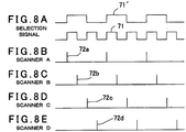
- FIG.8A to FIG.8E shows a selection signal 71 produced with respect to each of four laser scanners 3.
- the light emission signals 72a, 72b, 72c and 72d are generated.
- the light emission signals 72a, 72b, 72c and 72d By using the light emission signals 72a, 72b, 72c and 72d, light emission of four laser scanners 3 can be controlled.
- the masking of the distance measuring light detector 28 it would suffice if detection is possible only between the photodetection signals 72, which are adjacent to each other in terms of time. For instance, in a scanner A, masking of a light emitting source 26 of the scanner A should be performed so that detection is possible only between the light emission signal 72a and the light emission signal 72b.
- a selection signal 71" having a period of 1/2 times as long with respect to the selection signal 71 is produced and by combining HIGH and LOW of the two selection signals 71 and 71", the light emission signals 72 are produced.
- one light emitting source is provided with respect to one laser scanner 3 in the embodiment as described above, it may be so arranged that a plurality of light emitting sources are provided with respect to one laser scanner 3 and the plurality of light emitting sources emit light alternately using the selection signal 71.
Landscapes
- Physics & Mathematics (AREA)
- Engineering & Computer Science (AREA)
- Electromagnetism (AREA)
- Computer Networks & Wireless Communication (AREA)
- General Physics & Mathematics (AREA)
- Radar, Positioning & Navigation (AREA)
- Remote Sensing (AREA)
- Optical Radar Systems And Details Thereof (AREA)
Description
- The present invention relates to a laser scanner system, which has a plurality of scanners and acquires point cloud data in a wide range.
- As one of the usage methods of a laser scanner, a method is known, in which laser scanners are installed on a movable object such as an automobile and acquire point cloud data of a predetermined range along a moving line. A point cloud data thus acquired is used as a map data of a navigation system or is used for measuring a shape of building structure or is used as a data for judging a condition of a road surface.
- As one of the laser scanners, there is a laser scanner of TOF (TIME OF FLIGHT) type. The laser scanner emits a laser beam (a distance measuring light) by pulsed emitting, measures a distance of a projecting point (a measuring point) per each pulsed light by receiving a reflected light and based on a time required for a round trip of the pulsed light, and further, by scanning the laser beam within a range as required, point cloud data are acquired.
- Conventionally, in a case where a laser scanner is installed on a movable object, e.g. an automobile, the laser scanner is installed at a part where a visual field from the automobile is opened, e.g. one laser scanner is installed on a ceiling of the automobile, the emitted laser beam is scanned in a direction crossing a moving line, and the point cloud data within a predetermined range along the moving line is acquired. The publication, "Stanley: The Robot that Won the DARPA Grand Challenge", by S. Thrun et al. in Journal of Field Robotics, vol. 23, no. 9, p. 661 - 692 discloses a laser scanner system comprising several laser range finders. The laser scanner system is installed on a movable vehicle. Further, a main control device is provided. The publication C R: "T"; URL: https://www.mysick.com/saqqara/im0012759.pdf discloses a laser measurement system with two laser scanners. The respective scanning mirrors of the laser scanners are each disposed at positions as displaced by 180°. The two laser scanners are synchronized with one laser scanner as a MASTER mode and the other laser scanner as a SLAVE mode.
DE 10 2011 053 212 B3 discloses a laser scanner and a vehicle with a laser scanner. - In a case where the point cloud data are acquired by the laser scanner installed on the automobile, it is desirable that the automobile runs at the same speed as other vehicles. Further, in order to improve the measurement accuracy, it is desirable that the point cloud data are becoming denser. On the other hand, the density of the acquired point cloud data is determined by a scanning speed of the laser beam, a moving speed of the automobile and a light emission frequency of the pulsed light.
- Therefore, in order that a predetermined point cloud data density is satisfied under the condition where high density of the point cloud data is required, an increase of the light emission frequency is required. However, because of a restriction on a duty of a light emitting source, the increase of the light emission frequency is limited, and there have been problems where demands of a higher moving speed and a higher density of the point cloud data may have not been fulfilled sufficiently.
- It is an object of the present invention to provide a laser scanner system, by which it is possible to increase a moving speed and to have a higher density of the point cloud data.
- The object as described above, is solved by a laser scanner system according to
claim 1. - Further, in the laser scanner system according to the present invention, the laser scanner has a distance measuring unit, wherein the distance measuring unit has a light emitting source for emitting a pulsed light and a distance measuring light detector for receiving a reflection light from an object to be measured, and the distance measuring unit makes the light emitting source to emit based on the selection signal and restricts the distance measuring light detector so as to detect the reflection light only for a predetermined time period from the selection signal.
- Further, in the laser scanner system according to the present invention, the laser scanner comprises a rotary projecting unit for projecting a pulsed laser beam in rotary irradiation, and the main control device produces the selection signal so that the pulsed light has such light emission period corresponding to a rotation speed of the rotary projecting unit.
- Further, in the laser scanner system according to the present invention, the selection signal is produced, which sets a light emission period of a pulsed light so that a density of an acquired point cloud data become a predetermined value, by corresponding a moving speed of the movable object and a rotating speed of the rotary projecting unit.
- Furthermore, in the laser scanner system according to the present invention, the distance measuring unit has two or more light emitting sources and is configured so that light emission of the light emitting source is alternately selected based on the selection signal.
- According to the present invention, the laser scanner system comprises two or more laser scanners installed on a movable object and a main control device, wherein the laser scanner is arranged as a TOF type which performs distance measurement by rotary projection of a pulsed light, and wherein the main control device produces a selection signal, the laser scanner, which is alternately selected based on the selection signal, performs distance measurement by emitting a pulsed light, wherein the laser scanner, which performs distance measurement at the same time, is a selected one. As a result, interference between the laser scanners can be avoided, the acquisition of the point cloud data by a plurality of laser scanners become possible, and it becomes possible to increase the moving speed and increase the density of the point cloud data.
- Further, according to the present invention, in the laser scanner system, the laser scanner has a distance measuring unit, wherein the distance measuring unit has a light emitting source for emitting a pulsed light and a distance measuring light detector for receiving a reflection light from an object to be measured, and the distance measuring unit makes the light emitting source to emit based on the selection signal and restricts the distance measuring light detector so as to detect the reflection light only for a predetermined time period from the selection signal. As a result, interference between the laser scanners are even more avoided and acquisition of the point cloud data with higher accuracy becomes possible.
- Further, according to the present invention, in the laser scanner system, the laser scanner comprises a rotary projecting unit for projecting a pulsed laser beam in rotary irradiation, and the main control device produces the selection signal so that the pulsed light has such light emission period corresponding to a rotation speed of the rotary projecting unit. As a result, it is possible to obtain the point cloud data having the pitch interval as desired.
- Further, according to the present invention, in the laser scanner system, the selection signal is produced, which sets a light emission period of a pulsed light so that a density of an acquired point cloud data become a predetermined value, by corresponding a moving speed of the movable object and a rotating speed of the rotary projecting unit. As a result, it is possible to acquire point cloud data having the density as desired.
- Furthermore, according to the present invention, in the laser scanner system, the distance measuring unit has two or more light emitting sources and is configured so that light emission of the light emitting source is alternately selected based on the selection signal. As a result, distance measurement can be performed by using even more pulsed lights and point cloud data with higher density can be acquired.
-
-
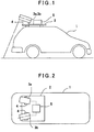
FIG.1 is a schematical side view to show an automobile where a laser scanner system according to an embodiment of the present invention is installed. -
FIG.2 is a plan view of the automobile as described above. -
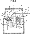
FIG.3 is a lateral cross-sectional view of a laser scanner used in the laser scanner system. -
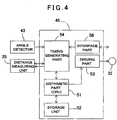
FIG.4 is a schematical block diagram of a laser scanner control unit. -
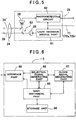
FIG.5 is a schematical block diagram of a distance measuring unit. -
FIG.6 is a schematical block diagram of a main control device. -
FIG.7A, FIG.7B and FIG.7C are drawings to explain a selection signal for controlling light emission timing of two laser scanners, andFIG.7D and FIG.7E are drawings to explain a masking which restrict a detection of reflection light of each of the laser scanners. -
FIG.8A, FIG.8B, FIG.8C, FIG.8D and FIG.8E are drawings to explain selection signals for controlling light emission timing of four laser scanners. - Description will be given below on an embodiment of the present invention by referring to the attached drawings.
- First, by referring to
FIG.1 and FIG.2 , description will be given on general features of an embodiment of the invention. - In the present embodiment, an automobile is used as a movable object. A
fixing base 2 is installed on an upper surface of anautomobile 1 and twolaser scanners fixing base 2. Thelaser scanners fixing base 2 via amount 4 in a condition where thelaser scanners main control device 5 is installed on theautomobile 1, and operations of thelaser scanners main control device 5. - Each of the
laser scanners automobile 1 and the laser beam is scanned within a range as required in horizontal direction and in up-and-down direction respectively. - The
laser scanners laser scanners main control device 5 so that one of distance measuring operations does not exert influence on the other distance measuring operation. - First, referring to
FIG.3 , description will be given on thelaser scanners laser scanner 3a and thelaser scanner 3b have the same structure, a description will be given below by regarding them as alaser scanner 3. Further, although a center line of thelaser scanner 3 is shown in a vertical direction inFIG.3 , the laser scanner is set in lateral direction when installed on thefixing base 2, and thelaser scanner 3 is arranged in a condition where the center line is tilted with respect to the horizontal direction and further tilted with respect to the advancing direction. - A
main unit case 7 is fixed on themount 4, and anupper cover 8 is air-tightly mounted on an upper surface of themain unit case 7. Themain unit case 7 and theupper cover 8 make up together a casing 9 with an air-tight structure. - At a center of an upper surface of the
main unit case 7, arecessed portion 11 is formed in downward direction and a body tube (lens barrel) 12 is provided at a center portion of the recessedportion 11 so as to penetrate in up-and-down direction. Aflange 13 is formed on thebody tube 12 and theflange 13 is fixed to the bottom of the recessedportion 11. - On an upper end of the
body tube 12, arotary base 17 is mounted viabearings 16. On therotary base 17, a rotary mechanism unit 18 (to be described later) and a rotary projecting unit 19 (to be described later) are provided. - The
body tube 12 has anoptical axis 21, which coincides with the central line, and amirror 22, as optical separating means, is provided on theoptical axis 21. Themirror 22 reflects a reflected light 29'. Further, acondenser lens 24 with aperture is provided on theoptical axis 21. - A
distance measuring unit 25 is provided on a reflection lightoptical axis 23 which is deflected by themirror 22. - A
light emitting source 26 is provided on the reflection lightoptical axis 23, and amirror 27 with aperture is disposed on the reflection lightoptical axis 23. Themirror 27 with aperture allows the reflection lightoptical axis 23 to pass, and further, the reflection lightoptical axis 23 is divided, and a distance measuringlight detector 28 is provided on the divided optical axis. - The
light emitting source 26 is driven by pulse, and a pulsed laser beam, which is a continuation of the pulsed light, is emitted from thelight emitting source 26. Thelight emitting source 26 is a semiconductor laser or the like, for instance, and emits pulsed laser beam of infrared light as adistance measuring light 29, and light emission is controlled in a condition as required by a laser scanner control unit 45 (to be described later). - The
pulsed laser beam 29 passes through themirror 27 with aperture and is reflected by themirror 22 on theoptical axis 21, passes through a hole of thecondenser lens 24 with aperture and is projected to therotary projecting unit 19. Further, it is arranged so that thepulsed laser beam 29 is projected to an object to be measured via adeflection mirror 37. - The reflection light reflected by the object to be measured enters the
condenser lens 24 with aperture via therotary projecting unit 19 and theoptical axis 21. The reflection light is then reflected by themirror 27 with aperture and enters the distance measuringlight detector 28. It is arranged so that one divided part of thepulsed laser beam 29 enters the distance measuringlight detector 28 as an internal reference light (not shown), and arranged so that a distance to the object to be measured is measured based on the reflected distance measuring light and the internal reference light. - Description will be given on the
rotary mechanism unit 18. - A
rotary motor 32 is provided on an upper surface of themain unit case 7 and arotary driving gear 33 is fitted into output shaft of therotary motor 32. Arotary gear 34 is provided on therotary base 17 and therotary gear 34 is engaged with therotary driving gear 33. It is so designed that therotary base 17 is rotated around theoptical axis 21 as the center via therotary driving gear 33 and therotary gear 34 by the driving of therotary motor 32. - On an upper surface of the
rotary base 17, a mirror holder (not shown) is provided, and thedeflection mirror 37 as a deflection optical member is supported by the mirror holder. Thedeflection mirror 37 is disposed on theoptical axis 21 and deflects thepulsed laser beam 29, which enters via thecondenser lens 24 with aperture, in horizontal direction. Thedeflection mirror 37 deflects the reflection light as reflected by the object to be measured in vertical direction and then directs the reflection light toward thecondenser lens 24 with aperture. - By driving the
rotary motor 32, therotary base 17 is rotated around theoptical axis 21 as the center via therotary driving gear 33 and therotary gear 34, and thedeflection mirror 37 is rotated integrally with therotary base 17. - An
angle detector 43 is provided between therotary base 17 and the recessedportion 11, and a relative rotation angle of therotary base 17 with respect to the main unit case 7 (the body tube 12) is detected by theangle detector 43. - The
rotary motor 32, therotary driving gear 33, therotary gear 34, thedeflection mirror 37, etc. make up together therotary projecting unit 19. - An upper portion of the
main unit case 7 is air-tightly covered by theupper cover 8 and therotary mechanism unit 18, therotary projecting unit 19, theangle detector 43, etc. are accommodated in theupper cover 8. Further, a circumferential surface of theupper cover 8 is transparent, and designed so that thepulsed laser beam 29 is projected through the circumferential surface so that the reflection light enters through the circumferential surface. - Inside the
main unit case 7, the laserscanner control unit 45 is provided. The laserscanner control unit 45 controls for emitting light and for measuring distance in thedistance measuring unit 25 and controls for scanning thepulsed laser beam 29 by therotary mechanism unit 18 based on the result of detection by theangle detector 43. - Further, based on the result of detection by the
angle detector 43, the laserscanner control unit 45 measures a rotation angle of therotary base 17, i.e. thedeflection mirror 37, acquires positional information of a measuring point by executing distance measurement and angle measurement per each pulse, and further acquires a point cloud data. - Referring to
FIG.4 , description will be given on general features of a control system including the laserscanner control unit 45. - A detection signal from the
angle detector 43 and a distance measurement result from thedistance measuring unit 25 are inputted in the laserscanner control unit 45. - Description will be given on general features of the laser
scanner control unit 45. - The laser
scanner control unit 45 comprises anarithmetic part 51 represented by a CPU for processing distance data acquired by thedistance measuring unit 25 and for corresponding an angle and a distance, astorage unit 52, a drivingpart 53 for driving and controlling therotary motor 32, aninterface part 58 for controlling input/output of signals such as control signals, data signals, etc. to and from themain control device 5, and atiming generating part 54, and the like, for generating a timing for angle detection and distance measurement. - In the
storage unit 52, various types of programs are stored. These programs include: a sequence program required for detection of distance measurement and detection of rotation angle, a calculation program, a measurement data processing program for executing the processing of measurement data, a timing generating program for synchronizing the detection of distance measurement and rotation angle of thedistance measuring unit 25 and a program and the like for integrally managing these programs. And further, data such as measurement data and the like are stored in thestorage unit 52. - The acquisition of the point cloud data by the
laser scanner 3 as a single unit is carried out as described below. - A
pulsed laser beam 29 as emitted from thelight emitting source 26 is reflected by themirror 22, passes through thecondenser lens 24 with aperture, is further deflected in horizontal direction by thedeflection mirror 37 and is projected. - A reflection light 29' from the object to be measured enters the
deflection mirror 37, is reflected by themirror 22 and themirror 27 with aperture and is received by the distance measuringlight detector 28. - Based on the reflection light 29' as received at the distance measuring
light detector 28, distance measurement is performed per each light pulse of the reflection light 29'. Further, a rotation angle at the time of detection of the light pulse is detected by theangle detector 43. Based on the distance measurement result and the rotation angle thus detected, positional data of the measuring point is acquired. - By reciprocally rotating the
rotary base 17 around theoptical axis 21 as the center by means of therotary motor 32, therotary projecting unit 19, i.e. thedeflection mirror 37, is reciprocally rotated. By reciprocally rotating thedeflection mirror 37, thedistance measuring light 29 is reciprocally scanned at a predetermined angle. It is to be noted that therotary base 17 may be rotated in one direction at a constant speed by therotary motor 32. - When the
automobile 1 is moved at a predetermined speed or when thedeflection mirror 37 is reciprocally rotated, thedistance measuring light 29 is scanned over a predetermined range, and a point cloud data of the predetermined range is acquired. - Referring to
FIG.5 , description will be given on general features of thedistance measuring unit 25. - By a light
emission driving part 61, thelight emitting source 26 is made to emit and light emission period or the like are controlled. The light receiving condition of the distance measuringlight detector 28 is controlled by aphotodetecting circuit 62, and in a case where the distance measuringlight detector 28 receives the reflection light 29', a photodetection signal is outputted to the laserscanner control unit 45 via thephotodetecting circuit 62. It is to be noted that one part of thedistance measuring light 29 as emitted from thelight emitting source 26 enters the distance measuringlight detector 28 via an internalreference light path 63 as an internal reference light. In the distance measurement based on the reflected light 29', by comparing the reflection light 29' and the internal reference light, it is possible to perform distance measurement with high accuracy. - Next, by referring to
FIG.6 , description will be given on themain control device 5. - The
main control device 5 primarily comprises a mainarithmetic part 65 as represented by a CPU, astorage unit 66, a clocksignal generating part 67, a selectionsignal generating part 68 and aninterface part 69. - The clock
signal generating part 67 issues a reference clock signal, and based on the reference clock signal, the selectionsignal generating part 68 produces a selection signal for controlling the light emission timing of thedistance measuring light 29 of each of thelaser scanners - The
interface part 69 is for performing communication to and from theinterface part 58 by the means as required such as wireless, wired communication, or the like and transmits the selection signal or a light emission control command as produced based on the selection signal to theinterface part 58. - In the
storage unit 66, various types of programs are stored. These programs include: a program for generating a selection signal, a communication program for performing communication of signals such as control signals, data signals, etc. to and from theinterface part 58 and theinterface part 69, and a program for controlling a giving and taking of the data and a data processing between the clocksignal generating part 67, the selectionsignal generating part 68 and theinterface part 69. - The
main control device 5 controls light emission timing of thedistance measuring light 29 of thelaser scanners laser scanners - For instance, when a reflection light of the
distance measuring light 29 emitted from onelaser scanner 3a enters theother laser scanner 3b and theother laser scanner 3b performs distance measurement according to the reflection light, the result of distance measurement by theother laser scanner 3b will be erroneous. Therefore, themain control device 5 controls a light emission timing of thedistance measuring light 29 of each of thelaser scanners laser scanners rotary projecting unit 19 as emitted by themselves respectively. - Referring to
FIG.7 , description will be given on an operation of the main·control device 5. -
FIG.7A shows aselection signal 71 produced based on a reference clock signal by the selectionsignal generating part 68, and theselection signal 71 is a rectangular wave with an equal time interval. Further, the period of theselection signal 71 is set in such a manner that a restriction of the load factor of thelight emitting source 26 is fulfilled and that the period will be in a time interval corresponding to a distance to be measured. - Based on the
selection signal 71,light emission signals laser scanners FIG.7A and FIG.7B ). - The
light emission signal 72a with respect to thelaser scanner 3a is generated at the timing of a starting edge of theselection signal 71, and thelight emission signal 72b with respect to thelaser scanner 3b is generated at the timing of a stopping edge of theselection signal 71. Therefore, thelaser scanners light emitting source 26 will be fulfilled. - Further, the time interval between the
light emission signal 72a of thelaser scanner 3a and thelight emission signal 72b of thelaser scanner 3b is set so as to satisfy the time corresponding to the distance to be measured. That is, the time interval between thelight emission signal 72a and thelight emission signal 72b is longer than a distance measuring time by one pulsed light. Under such setting, for instance, there is no chance that the reflection light of thedistance measuring light 29 as emitted from thelaser scanner 3a enters thelaser scanner 3b after thelight emission signal 72b of thelaser scanner 3b. - The
light emission signals interface part 69 to each of theinterface parts 58 as a light emission synchronizing signal of each of thedistance measuring units 25 of thelaser scanners light emission signal 72a is issued, only thelaser scanner 3a emits the pulsed light and performs distance measurement. In a case where thelight emission signal 72b is issued, only thelaser scanner 3b emits the pulsed light and performs distance measurement. Therefore, thelight emission signals laser scanners laser scanners - Each of the light emission signals 72 is inputted respectively to the light
emission driving part 61 and thephotodetecting circuit 62 of thedistance measuring unit 25 via the laserscanner control unit 45. - The light
emission driving part 61 is operated so that thelight emitting source 26 emits pulsed light based on the light emission signal 72 and thephotodetecting circuit 62 is operated so that a detection timing of the reflection light 29' is controlled based on the light emission signal 72. - It is to be noted that it may be arranged in such a manner that the
selection signal 71 is transmitted from themain control device 5 to thelaser scanner 3 and that thelight emission signals scanner control unit 45. - That is, the
main control device 5 transmits theselection signal 71 from theinterface part 69 to theinterface part 58 with respect to each of thelaser scanners 3 respectively and produces the light emission signal 72 based on theselection signal 71 by the laserscanner control unit 45. The light emission signal 72 is inputted to thedistance measuring unit 25, a pulsed light emission of thelight emitting source 26 is controlled based on the light emission signal 72, and the detection of thephotodetecting circuit 62 is controlled. - The laser
scanner control unit 45 controls photodetecting conditions of the distance measuringlight detector 28, and controls in such a manner that a distance measurement is performed by judging the reflection light 29' first received from the moment when the light emission signal is issued as a reflection light of thedistance measuring light 29 issued by itself. By this judgment, it is possible to reliably prevent erroneous measurement based on the reflection light with respect to theother laser scanner 3. -
FIG.7D and FIG.7E shows a method of distinguishing the reflection light 29' in order to prevent erroneous measurement more reliably. - In the distinguishing method as shown in
FIG.7D and FIG.7E , a time to detect the reflection light 29' is limited with respect to the distance measuringlight detectors 28 of thelaser scanners light detector 28 and the detection of the reflection light 29' is restricted. - For instance, in the
laser scanner 3a, when thelight emission signal 72a is inputted to thephotodetecting circuit 62, thephotodetecting circuit 62 can detect the reflection light 29' only during the period from the moment of input of thelight emission signal 72a to the moment when thelight emission signal 72b is issued. Similarly, in thelaser scanner 3b, thephotodetecting circuit 62 can detect the reflection light 29' only during the time from the issuing of thelight emission signal 72b to the issuing of thelight emission signal 72a. - With respect to the distance measuring
light detector 28 of each of thelaser scanner 3a and thelaser scanner 3b, by carrying out themaskings laser scanners - Next, under the condition where the
laser scanners automobile 1, theoptical axis 21, i.e. the rotation center of therotary projecting unit 19, is tilted with respect to the horizontality and is also tilted with respect to the advancing direction. Therefore, thedistance measuring light 29 emitted from thedeflection mirror 37 is emitted in rotary projection within a plane, which is tilted with respect to the advancing direction. - The density of the point cloud data obtained by the
laser scanners deflection mirror 37 driven by therotary motor 32 and by the moving speed of theautomobile 1 where thelaser scanners 3 are installed. - The light emitting period of the pulsed light is determined by the setting of the period of the
selection signal 71. Therefore, by taking the rotating speed of thedeflection mirror 37 into consideration and by determining the light emitting period, a light emitting pitch (light emitting interval) in rotating direction of thedistance measuring light 29 can be set up. Further, by taking the rotating speed of thedeflection mirror 37 and the moving speed of theautomobile 1 into consideration, a pitch in the moving direction can be set up. - Therefore, by appropriately setting up the light emitting period, the rotation speed of the
deflection mirror 37 and the moving speed of theautomobile 1, it is possible to set up the density of the point cloud data to a condition as desired, for instance, to set up the density of the point cloud data to a constant level. It is to be noted that as for the moving speed of theautomobile 1, the laser scanner system may be provided with a speed detector, or a speed signal may be obtained from a speedometer installed on theautomobile 1. - In
FIG.7A to FIG.7C as described above, aselection signal 71 produced with respect to the twolaser scanners 3 is shown, while it is possible to control light emission of evenmore laser scanners 3 by produced selection signals with different periods and by combining selection signals with different periods. - For instance,
FIG.8A to FIG.8E shows aselection signal 71 produced with respect to each of fourlaser scanners 3. - By producing a selection signal 71' having a period which is twice as long with respect to a
selection signal 71, and by combining HIGH and LOW of the twoselection signals 71 and 71', thelight emission signals light emission signals laser scanners 3 can be controlled. Further, as for the masking of the distance measuringlight detector 28, it would suffice if detection is possible only between the photodetection signals 72, which are adjacent to each other in terms of time. For instance, in a scanner A, masking of alight emitting source 26 of the scanner A should be performed so that detection is possible only between thelight emission signal 72a and thelight emission signal 72b. - It is to be noted that it may be so arranged that a
selection signal 71" having a period of 1/2 times as long with respect to theselection signal 71 is produced and by combining HIGH and LOW of the twoselection signals - Further, although one light emitting source is provided with respect to one
laser scanner 3 in the embodiment as described above, it may be so arranged that a plurality of light emitting sources are provided with respect to onelaser scanner 3 and the plurality of light emitting sources emit light alternately using theselection signal 71.
Claims (5)
- A laser scanner system, comprising two or more laser scanners (3a, 3b) installed on a movable object (1) and a main control device (5), wherein said laser scanners each have a distance measuring unit (25) and are arranged as a TOF type which performs distance measurement by rotary projection of a pulsed light, wherein said distance measuring unit has a light emitting source (26) for emitting a pulsed light and a distance measuring light detector (28) for receiving a reflection light (29') from an object to be measured, characterized in that said main control device produces a selection signal which is a rectangular wave with an equal time interval, wherein each of said distance measuring units of said laser scanners, which is alternately selected based on said selection signal, performs distance measurement on said light emitting source by emitting a pulsed light, wherein said laser scanner, which performs distance measurement at the same time, is a selected one, detects said reflection light only while said selection signal to a next selection signal is issued, carries out maskings (73a, 73b) to said distance measuring light detector at a different timing in such a manner that detectable ranges of the laser scanner do not overlap and is configured so as to restrict the detection of the reflection light.
- A laser scanner system according to claim 1, wherein said laser scanners (3a, 3b) comprise a rotary projecting unit (19) for projecting a pulsed laser beam (29) in rotary irradiation, and said main control device (5) produces said selection signal so that the pulsed light has such light emission period corresponding to a rotation speed of said rotary projecting unit.
- A laser scanner system according to claim 1, wherein said selection signal is produced, which sets a light emission period of a pulsed light so that a density of an acquired point cloud data become a predetermined value, by corresponding a moving speed of said movable object (1) and a rotating speed of said rotary projecting unit (19).
- A laser scanner system according to claim 1, wherein said distance measuring unit (25) has two or more light emitting sources (26) and is configured so that light emission of said light emitting source is alternately selected based on said selection signal.
- A laser scanner system according to claim 1, wherein said laser scanners (3a, 3b) are configured so as to be set so that each center line is tilted with respect to a horizontal direction and further tilted in a spreading direction with respect to an advancing direction.
Applications Claiming Priority (1)
| Application Number | Priority Date | Filing Date | Title |
|---|---|---|---|
| JP2014116088A JP6347674B2 (en) | 2014-06-04 | 2014-06-04 | Laser scanner system |
Publications (2)
| Publication Number | Publication Date |
|---|---|
| EP2952929A1 EP2952929A1 (en) | 2015-12-09 |
| EP2952929B1 true EP2952929B1 (en) | 2019-12-11 |
Family
ID=53269415
Family Applications (1)
| Application Number | Title | Priority Date | Filing Date |
|---|---|---|---|
| EP15170355.0A Active EP2952929B1 (en) | 2014-06-04 | 2015-06-02 | Laser scanner system |
Country Status (3)
| Country | Link |
|---|---|
| US (1) | US10088570B2 (en) |
| EP (1) | EP2952929B1 (en) |
| JP (1) | JP6347674B2 (en) |
Families Citing this family (7)
| Publication number | Priority date | Publication date | Assignee | Title |
|---|---|---|---|---|
| US11320831B2 (en) * | 2018-01-23 | 2022-05-03 | Panasonic Intellectual Property Management Co., Ltd. | Mover, mover control system, method of detecting object by mover, moving system, and method of controlling mover |
| CN108959173B (en) * | 2018-07-06 | 2022-02-11 | 北京数字绿土科技有限公司 | Method and device for resolving point cloud data of laser radar |
| IT201900000995A1 (en) * | 2019-01-23 | 2020-07-23 | Nuovo Pignone Tecnologie Srl | INDUSTRIAL ROBOTIC EQUIPMENT WITH IMPROVED PROCESSING PATH GENERATION AND METHOD TO OPERATE INDUSTRIAL ROBOTIC EQUIPMENT ACCORDING TO AN IMPROVED PROCESSING PATH |
| JP7247413B2 (en) * | 2020-06-29 | 2023-03-28 | 京セラ株式会社 | ELECTRONIC DEVICE, ELECTRONIC DEVICE CONTROL METHOD, AND PROGRAM |
| CN113701626B (en) * | 2021-08-10 | 2023-08-04 | 哈尔滨岛田大鹏工业股份有限公司 | Automobile longitudinal beam 3D machine vision detection method |
| CN114325738B (en) * | 2021-12-23 | 2023-01-10 | 探维科技(北京)有限公司 | Method for measuring distance and laser radar |
| CN115047479B (en) * | 2022-08-12 | 2022-11-01 | 中北大学 | Cloud and smoke interference recognition device for unmanned aerial vehicle laser altimeter |
Family Cites Families (12)
| Publication number | Priority date | Publication date | Assignee | Title |
|---|---|---|---|---|
| US5495337A (en) * | 1991-11-06 | 1996-02-27 | Machine Vision Products, Inc. | Method of visualizing minute particles |
| JP4486737B2 (en) * | 2000-07-14 | 2010-06-23 | アジア航測株式会社 | Spatial information generation device for mobile mapping |
| CN101688774A (en) * | 2006-07-13 | 2010-03-31 | 威力登音响公司 | High definition lidar system |
| JP5073256B2 (en) | 2006-09-22 | 2012-11-14 | 株式会社トプコン | POSITION MEASUREMENT DEVICE, POSITION MEASUREMENT METHOD, AND POSITION MEASUREMENT PROGRAM |
| JP5912234B2 (en) * | 2010-07-16 | 2016-04-27 | 株式会社トプコン | measuring device |
| DE102011053212B3 (en) * | 2011-09-02 | 2012-10-04 | Sick Ag | Optoelectronic sensor and method for detecting objects in a surveillance area |
| JP2013113670A (en) * | 2011-11-28 | 2013-06-10 | Mitsubishi Electric Corp | Laser radar system, laser distance measuring device and control device |
| JP6025014B2 (en) * | 2012-02-22 | 2016-11-16 | 株式会社リコー | Distance measuring device |
| GB2501466A (en) * | 2012-04-02 | 2013-10-30 | Univ Oxford | Localising transportable apparatus |
| KR102038533B1 (en) * | 2012-06-14 | 2019-10-31 | 한국전자통신연구원 | Laser Radar System and Method for Acquiring Target Image |
| NL2010463C2 (en) * | 2013-03-15 | 2014-09-16 | Cyclomedia Technology B V | METHOD FOR GENERATING A PANORAMA IMAGE |
| US10203399B2 (en) * | 2013-11-12 | 2019-02-12 | Big Sky Financial Corporation | Methods and apparatus for array based LiDAR systems with reduced interference |
-
2014
- 2014-06-04 JP JP2014116088A patent/JP6347674B2/en active Active
-
2015
- 2015-05-29 US US14/725,382 patent/US10088570B2/en active Active
- 2015-06-02 EP EP15170355.0A patent/EP2952929B1/en active Active
Non-Patent Citations (1)
| Title |
|---|
| None * |
Also Published As
| Publication number | Publication date |
|---|---|
| US20150355331A1 (en) | 2015-12-10 |
| EP2952929A1 (en) | 2015-12-09 |
| JP6347674B2 (en) | 2018-06-27 |
| JP2015230226A (en) | 2015-12-21 |
| US10088570B2 (en) | 2018-10-02 |
Similar Documents
| Publication | Publication Date | Title |
|---|---|---|
| EP2952929B1 (en) | Laser scanner system | |
| EP2053354B1 (en) | Laser surveying system | |
| US11402506B2 (en) | Laser measuring method and laser measuring instrument | |
| EP2407752B1 (en) | Measuring device | |
| EP2381272B1 (en) | Laser scanner | |
| JP6135120B2 (en) | Distance measuring device, distance measuring method and program | |
| US7522268B2 (en) | Distance measuring device | |
| EP1801538B1 (en) | Distance measuring method and distance measuring device | |
| EP2447666B1 (en) | Laser surveying instrument | |
| US7633609B2 (en) | Measuring system | |
| EP3919858A1 (en) | Rotary laser device and laser ranging method | |
| CN108205141B (en) | Method for operating a laser distance measuring device | |
| CN109116322A (en) | A kind of displacement and the light echo removing method apart from laser radar system | |
| JP6186863B2 (en) | Ranging device and program | |
| JP4851737B2 (en) | Distance measuring device | |
| CN112292609A (en) | Object detection device and photodetector | |
| JP6749191B2 (en) | Scanner and surveying equipment | |
| JP2020148633A (en) | Object detector | |
| EP4141385A1 (en) | Surveying instrument | |
| JP2021162466A (en) | State detection device and state detection method for transmission portion in electromagnetic wave scanning device | |
| CN113960563A (en) | Indoor building laser radar measuring apparatu of higher accuracy | |
| KR20200127568A (en) | Time of flight sensor using digital micromirror device and operating method thereof |
Legal Events
| Date | Code | Title | Description |
|---|---|---|---|
| PUAI | Public reference made under article 153(3) epc to a published international application that has entered the european phase |
Free format text: ORIGINAL CODE: 0009012 |
|
| 17P | Request for examination filed |
Effective date: 20150602 |
|
| AK | Designated contracting states |
Kind code of ref document: A1 Designated state(s): AL AT BE BG CH CY CZ DE DK EE ES FI FR GB GR HR HU IE IS IT LI LT LU LV MC MK MT NL NO PL PT RO RS SE SI SK SM TR |
|
| AX | Request for extension of the european patent |
Extension state: BA ME |
|
| RAP1 | Party data changed (applicant data changed or rights of an application transferred) |
Owner name: KABUSHIKI KAISHA TOPCON |
|
| RBV | Designated contracting states (corrected) |
Designated state(s): AL AT BE BG CH CY CZ DE DK EE ES FI FR GB GR HR HU IE IS IT LI LT LU LV MC MK MT NL NO PL PT RO RS SE SI SK SM TR |
|
| STAA | Information on the status of an ep patent application or granted ep patent |
Free format text: STATUS: EXAMINATION IS IN PROGRESS |
|
| 17Q | First examination report despatched |
Effective date: 20171213 |
|
| REG | Reference to a national code |
Ref country code: DE Ref legal event code: R079 Ref document number: 602015043330 Country of ref document: DE Free format text: PREVIOUS MAIN CLASS: G01S0017420000 Ipc: G01S0007481000 |
|
| GRAJ | Information related to disapproval of communication of intention to grant by the applicant or resumption of examination proceedings by the epo deleted |
Free format text: ORIGINAL CODE: EPIDOSDIGR1 |
|
| GRAP | Despatch of communication of intention to grant a patent |
Free format text: ORIGINAL CODE: EPIDOSNIGR1 |
|
| GRAP | Despatch of communication of intention to grant a patent |
Free format text: ORIGINAL CODE: EPIDOSNIGR1 |
|
| STAA | Information on the status of an ep patent application or granted ep patent |
Free format text: STATUS: GRANT OF PATENT IS INTENDED |
|
| RIC1 | Information provided on ipc code assigned before grant |
Ipc: G01S 17/87 20060101ALI20190607BHEP Ipc: G01S 17/89 20060101ALI20190607BHEP Ipc: G01S 7/481 20060101AFI20190607BHEP Ipc: G01S 17/42 20060101ALI20190607BHEP |
|
| INTG | Intention to grant announced |
Effective date: 20190710 |
|
| GRAS | Grant fee paid |
Free format text: ORIGINAL CODE: EPIDOSNIGR3 |
|
| GRAA | (expected) grant |
Free format text: ORIGINAL CODE: 0009210 |
|
| STAA | Information on the status of an ep patent application or granted ep patent |
Free format text: STATUS: THE PATENT HAS BEEN GRANTED |
|
| AK | Designated contracting states |
Kind code of ref document: B1 Designated state(s): AL AT BE BG CH CY CZ DE DK EE ES FI FR GB GR HR HU IE IS IT LI LT LU LV MC MK MT NL NO PL PT RO RS SE SI SK SM TR |
|
| REG | Reference to a national code |
Ref country code: GB Ref legal event code: FG4D |
|
| REG | Reference to a national code |
Ref country code: CH Ref legal event code: EP |
|
| REG | Reference to a national code |
Ref country code: AT Ref legal event code: REF Ref document number: 1212744 Country of ref document: AT Kind code of ref document: T Effective date: 20191215 |
|
| REG | Reference to a national code |
Ref country code: DE Ref legal event code: R096 Ref document number: 602015043330 Country of ref document: DE |
|
| REG | Reference to a national code |
Ref country code: IE Ref legal event code: FG4D |
|
| REG | Reference to a national code |
Ref country code: CH Ref legal event code: NV Representative=s name: VALIPAT S.A. C/O BOVARD SA NEUCHATEL, CH |
|
| REG | Reference to a national code |
Ref country code: NL Ref legal event code: MP Effective date: 20191211 |
|
| REG | Reference to a national code |
Ref country code: LT Ref legal event code: MG4D |
|
| PG25 | Lapsed in a contracting state [announced via postgrant information from national office to epo] |
Ref country code: FI Free format text: LAPSE BECAUSE OF FAILURE TO SUBMIT A TRANSLATION OF THE DESCRIPTION OR TO PAY THE FEE WITHIN THE PRESCRIBED TIME-LIMIT Effective date: 20191211 Ref country code: BG Free format text: LAPSE BECAUSE OF FAILURE TO SUBMIT A TRANSLATION OF THE DESCRIPTION OR TO PAY THE FEE WITHIN THE PRESCRIBED TIME-LIMIT Effective date: 20200311 Ref country code: NO Free format text: LAPSE BECAUSE OF FAILURE TO SUBMIT A TRANSLATION OF THE DESCRIPTION OR TO PAY THE FEE WITHIN THE PRESCRIBED TIME-LIMIT Effective date: 20200311 Ref country code: SE Free format text: LAPSE BECAUSE OF FAILURE TO SUBMIT A TRANSLATION OF THE DESCRIPTION OR TO PAY THE FEE WITHIN THE PRESCRIBED TIME-LIMIT Effective date: 20191211 Ref country code: LV Free format text: LAPSE BECAUSE OF FAILURE TO SUBMIT A TRANSLATION OF THE DESCRIPTION OR TO PAY THE FEE WITHIN THE PRESCRIBED TIME-LIMIT Effective date: 20191211 Ref country code: LT Free format text: LAPSE BECAUSE OF FAILURE TO SUBMIT A TRANSLATION OF THE DESCRIPTION OR TO PAY THE FEE WITHIN THE PRESCRIBED TIME-LIMIT Effective date: 20191211 Ref country code: GR Free format text: LAPSE BECAUSE OF FAILURE TO SUBMIT A TRANSLATION OF THE DESCRIPTION OR TO PAY THE FEE WITHIN THE PRESCRIBED TIME-LIMIT Effective date: 20200312 |
|
| PG25 | Lapsed in a contracting state [announced via postgrant information from national office to epo] |
Ref country code: HR Free format text: LAPSE BECAUSE OF FAILURE TO SUBMIT A TRANSLATION OF THE DESCRIPTION OR TO PAY THE FEE WITHIN THE PRESCRIBED TIME-LIMIT Effective date: 20191211 Ref country code: RS Free format text: LAPSE BECAUSE OF FAILURE TO SUBMIT A TRANSLATION OF THE DESCRIPTION OR TO PAY THE FEE WITHIN THE PRESCRIBED TIME-LIMIT Effective date: 20191211 |
|
| PG25 | Lapsed in a contracting state [announced via postgrant information from national office to epo] |
Ref country code: AL Free format text: LAPSE BECAUSE OF FAILURE TO SUBMIT A TRANSLATION OF THE DESCRIPTION OR TO PAY THE FEE WITHIN THE PRESCRIBED TIME-LIMIT Effective date: 20191211 |
|
| PG25 | Lapsed in a contracting state [announced via postgrant information from national office to epo] |
Ref country code: PT Free format text: LAPSE BECAUSE OF FAILURE TO SUBMIT A TRANSLATION OF THE DESCRIPTION OR TO PAY THE FEE WITHIN THE PRESCRIBED TIME-LIMIT Effective date: 20200506 Ref country code: NL Free format text: LAPSE BECAUSE OF FAILURE TO SUBMIT A TRANSLATION OF THE DESCRIPTION OR TO PAY THE FEE WITHIN THE PRESCRIBED TIME-LIMIT Effective date: 20191211 Ref country code: RO Free format text: LAPSE BECAUSE OF FAILURE TO SUBMIT A TRANSLATION OF THE DESCRIPTION OR TO PAY THE FEE WITHIN THE PRESCRIBED TIME-LIMIT Effective date: 20191211 Ref country code: EE Free format text: LAPSE BECAUSE OF FAILURE TO SUBMIT A TRANSLATION OF THE DESCRIPTION OR TO PAY THE FEE WITHIN THE PRESCRIBED TIME-LIMIT Effective date: 20191211 Ref country code: ES Free format text: LAPSE BECAUSE OF FAILURE TO SUBMIT A TRANSLATION OF THE DESCRIPTION OR TO PAY THE FEE WITHIN THE PRESCRIBED TIME-LIMIT Effective date: 20191211 Ref country code: CZ Free format text: LAPSE BECAUSE OF FAILURE TO SUBMIT A TRANSLATION OF THE DESCRIPTION OR TO PAY THE FEE WITHIN THE PRESCRIBED TIME-LIMIT Effective date: 20191211 |
|
| PG25 | Lapsed in a contracting state [announced via postgrant information from national office to epo] |
Ref country code: SM Free format text: LAPSE BECAUSE OF FAILURE TO SUBMIT A TRANSLATION OF THE DESCRIPTION OR TO PAY THE FEE WITHIN THE PRESCRIBED TIME-LIMIT Effective date: 20191211 Ref country code: SK Free format text: LAPSE BECAUSE OF FAILURE TO SUBMIT A TRANSLATION OF THE DESCRIPTION OR TO PAY THE FEE WITHIN THE PRESCRIBED TIME-LIMIT Effective date: 20191211 Ref country code: IS Free format text: LAPSE BECAUSE OF FAILURE TO SUBMIT A TRANSLATION OF THE DESCRIPTION OR TO PAY THE FEE WITHIN THE PRESCRIBED TIME-LIMIT Effective date: 20200411 |
|
| REG | Reference to a national code |
Ref country code: DE Ref legal event code: R097 Ref document number: 602015043330 Country of ref document: DE |
|
| REG | Reference to a national code |
Ref country code: AT Ref legal event code: MK05 Ref document number: 1212744 Country of ref document: AT Kind code of ref document: T Effective date: 20191211 |
|
| PLBE | No opposition filed within time limit |
Free format text: ORIGINAL CODE: 0009261 |
|
| STAA | Information on the status of an ep patent application or granted ep patent |
Free format text: STATUS: NO OPPOSITION FILED WITHIN TIME LIMIT |
|
| PG25 | Lapsed in a contracting state [announced via postgrant information from national office to epo] |
Ref country code: DK Free format text: LAPSE BECAUSE OF FAILURE TO SUBMIT A TRANSLATION OF THE DESCRIPTION OR TO PAY THE FEE WITHIN THE PRESCRIBED TIME-LIMIT Effective date: 20191211 |
|
| 26N | No opposition filed |
Effective date: 20200914 |
|
| PG25 | Lapsed in a contracting state [announced via postgrant information from national office to epo] |
Ref country code: AT Free format text: LAPSE BECAUSE OF FAILURE TO SUBMIT A TRANSLATION OF THE DESCRIPTION OR TO PAY THE FEE WITHIN THE PRESCRIBED TIME-LIMIT Effective date: 20191211 Ref country code: SI Free format text: LAPSE BECAUSE OF FAILURE TO SUBMIT A TRANSLATION OF THE DESCRIPTION OR TO PAY THE FEE WITHIN THE PRESCRIBED TIME-LIMIT Effective date: 20191211 |
|
| PG25 | Lapsed in a contracting state [announced via postgrant information from national office to epo] |
Ref country code: MC Free format text: LAPSE BECAUSE OF FAILURE TO SUBMIT A TRANSLATION OF THE DESCRIPTION OR TO PAY THE FEE WITHIN THE PRESCRIBED TIME-LIMIT Effective date: 20191211 Ref country code: IT Free format text: LAPSE BECAUSE OF FAILURE TO SUBMIT A TRANSLATION OF THE DESCRIPTION OR TO PAY THE FEE WITHIN THE PRESCRIBED TIME-LIMIT Effective date: 20191211 |
|
| PG25 | Lapsed in a contracting state [announced via postgrant information from national office to epo] |
Ref country code: PL Free format text: LAPSE BECAUSE OF FAILURE TO SUBMIT A TRANSLATION OF THE DESCRIPTION OR TO PAY THE FEE WITHIN THE PRESCRIBED TIME-LIMIT Effective date: 20191211 |
|
| GBPC | Gb: european patent ceased through non-payment of renewal fee |
Effective date: 20200602 |
|
| PG25 | Lapsed in a contracting state [announced via postgrant information from national office to epo] |
Ref country code: LU Free format text: LAPSE BECAUSE OF NON-PAYMENT OF DUE FEES Effective date: 20200602 |
|
| REG | Reference to a national code |
Ref country code: BE Ref legal event code: MM Effective date: 20200630 |
|
| PG25 | Lapsed in a contracting state [announced via postgrant information from national office to epo] |
Ref country code: GB Free format text: LAPSE BECAUSE OF NON-PAYMENT OF DUE FEES Effective date: 20200602 Ref country code: IE Free format text: LAPSE BECAUSE OF NON-PAYMENT OF DUE FEES Effective date: 20200602 Ref country code: FR Free format text: LAPSE BECAUSE OF NON-PAYMENT OF DUE FEES Effective date: 20200630 |
|
| PG25 | Lapsed in a contracting state [announced via postgrant information from national office to epo] |
Ref country code: BE Free format text: LAPSE BECAUSE OF NON-PAYMENT OF DUE FEES Effective date: 20200630 |
|
| PG25 | Lapsed in a contracting state [announced via postgrant information from national office to epo] |
Ref country code: TR Free format text: LAPSE BECAUSE OF FAILURE TO SUBMIT A TRANSLATION OF THE DESCRIPTION OR TO PAY THE FEE WITHIN THE PRESCRIBED TIME-LIMIT Effective date: 20191211 Ref country code: MT Free format text: LAPSE BECAUSE OF FAILURE TO SUBMIT A TRANSLATION OF THE DESCRIPTION OR TO PAY THE FEE WITHIN THE PRESCRIBED TIME-LIMIT Effective date: 20191211 Ref country code: CY Free format text: LAPSE BECAUSE OF FAILURE TO SUBMIT A TRANSLATION OF THE DESCRIPTION OR TO PAY THE FEE WITHIN THE PRESCRIBED TIME-LIMIT Effective date: 20191211 |
|
| PG25 | Lapsed in a contracting state [announced via postgrant information from national office to epo] |
Ref country code: MK Free format text: LAPSE BECAUSE OF FAILURE TO SUBMIT A TRANSLATION OF THE DESCRIPTION OR TO PAY THE FEE WITHIN THE PRESCRIBED TIME-LIMIT Effective date: 20191211 |
|
| PGFP | Annual fee paid to national office [announced via postgrant information from national office to epo] |
Ref country code: DE Payment date: 20230502 Year of fee payment: 9 |
|
| PGFP | Annual fee paid to national office [announced via postgrant information from national office to epo] |
Ref country code: CH Payment date: 20230702 Year of fee payment: 9 |