EP2925556B1 - Charging an electrical energy store on an electric vehicle at a socket with reduction of the charging current after failure and restoration of the power supply - Google Patents
Charging an electrical energy store on an electric vehicle at a socket with reduction of the charging current after failure and restoration of the power supply Download PDFInfo
- Publication number
- EP2925556B1 EP2925556B1 EP13795487.1A EP13795487A EP2925556B1 EP 2925556 B1 EP2925556 B1 EP 2925556B1 EP 13795487 A EP13795487 A EP 13795487A EP 2925556 B1 EP2925556 B1 EP 2925556B1
- Authority
- EP
- European Patent Office
- Prior art keywords
- charging current
- charging
- power supply
- current limit
- vehicle
- Prior art date
- Legal status (The legal status is an assumption and is not a legal conclusion. Google has not performed a legal analysis and makes no representation as to the accuracy of the status listed.)
- Active
Links
- 230000009467 reduction Effects 0.000 title claims description 22
- 238000000034 method Methods 0.000 claims description 59
- 238000004146 energy storage Methods 0.000 claims description 8
- 230000000717 retained effect Effects 0.000 claims 1
- 230000008569 process Effects 0.000 description 27
- 230000007246 mechanism Effects 0.000 description 7
- 239000004020 conductor Substances 0.000 description 6
- 230000008878 coupling Effects 0.000 description 5
- 238000010168 coupling process Methods 0.000 description 5
- 238000005859 coupling reaction Methods 0.000 description 5
- 238000010616 electrical installation Methods 0.000 description 4
- 238000009434 installation Methods 0.000 description 4
- 230000008859 change Effects 0.000 description 3
- 230000001960 triggered effect Effects 0.000 description 3
- 230000000694 effects Effects 0.000 description 2
- 238000003780 insertion Methods 0.000 description 2
- 240000006829 Ficus sundaica Species 0.000 description 1
- 239000004606 Fillers/Extenders Substances 0.000 description 1
- 230000009471 action Effects 0.000 description 1
- 239000003990 capacitor Substances 0.000 description 1
- 238000002485 combustion reaction Methods 0.000 description 1
- 230000001419 dependent effect Effects 0.000 description 1
- 238000001514 detection method Methods 0.000 description 1
- 230000007935 neutral effect Effects 0.000 description 1
- 230000001681 protective effect Effects 0.000 description 1
- 230000004044 response Effects 0.000 description 1
Images

Classifications
-
- H—ELECTRICITY
- H02—GENERATION; CONVERSION OR DISTRIBUTION OF ELECTRIC POWER
- H02J—CIRCUIT ARRANGEMENTS OR SYSTEMS FOR SUPPLYING OR DISTRIBUTING ELECTRIC POWER; SYSTEMS FOR STORING ELECTRIC ENERGY
- H02J13/00—Circuit arrangements for providing remote indication of network conditions, e.g. an instantaneous record of the open or closed condition of each circuitbreaker in the network; Circuit arrangements for providing remote control of switching means in a power distribution network, e.g. switching in and out of current consumers by using a pulse code signal carried by the network
- H02J13/00006—Circuit arrangements for providing remote indication of network conditions, e.g. an instantaneous record of the open or closed condition of each circuitbreaker in the network; Circuit arrangements for providing remote control of switching means in a power distribution network, e.g. switching in and out of current consumers by using a pulse code signal carried by the network characterised by information or instructions transport means between the monitoring, controlling or managing units and monitored, controlled or operated power network element or electrical equipment
- H02J13/00007—Circuit arrangements for providing remote indication of network conditions, e.g. an instantaneous record of the open or closed condition of each circuitbreaker in the network; Circuit arrangements for providing remote control of switching means in a power distribution network, e.g. switching in and out of current consumers by using a pulse code signal carried by the network characterised by information or instructions transport means between the monitoring, controlling or managing units and monitored, controlled or operated power network element or electrical equipment using the power network as support for the transmission
- H02J13/00009—Circuit arrangements for providing remote indication of network conditions, e.g. an instantaneous record of the open or closed condition of each circuitbreaker in the network; Circuit arrangements for providing remote control of switching means in a power distribution network, e.g. switching in and out of current consumers by using a pulse code signal carried by the network characterised by information or instructions transport means between the monitoring, controlling or managing units and monitored, controlled or operated power network element or electrical equipment using the power network as support for the transmission using pulsed signals
-
- B—PERFORMING OPERATIONS; TRANSPORTING
- B60—VEHICLES IN GENERAL
- B60L—PROPULSION OF ELECTRICALLY-PROPELLED VEHICLES; SUPPLYING ELECTRIC POWER FOR AUXILIARY EQUIPMENT OF ELECTRICALLY-PROPELLED VEHICLES; ELECTRODYNAMIC BRAKE SYSTEMS FOR VEHICLES IN GENERAL; MAGNETIC SUSPENSION OR LEVITATION FOR VEHICLES; MONITORING OPERATING VARIABLES OF ELECTRICALLY-PROPELLED VEHICLES; ELECTRIC SAFETY DEVICES FOR ELECTRICALLY-PROPELLED VEHICLES
- B60L3/00—Electric devices on electrically-propelled vehicles for safety purposes; Monitoring operating variables, e.g. speed, deceleration or energy consumption
-
- B—PERFORMING OPERATIONS; TRANSPORTING
- B60—VEHICLES IN GENERAL
- B60L—PROPULSION OF ELECTRICALLY-PROPELLED VEHICLES; SUPPLYING ELECTRIC POWER FOR AUXILIARY EQUIPMENT OF ELECTRICALLY-PROPELLED VEHICLES; ELECTRODYNAMIC BRAKE SYSTEMS FOR VEHICLES IN GENERAL; MAGNETIC SUSPENSION OR LEVITATION FOR VEHICLES; MONITORING OPERATING VARIABLES OF ELECTRICALLY-PROPELLED VEHICLES; ELECTRIC SAFETY DEVICES FOR ELECTRICALLY-PROPELLED VEHICLES
- B60L53/00—Methods of charging batteries, specially adapted for electric vehicles; Charging stations or on-board charging equipment therefor; Exchange of energy storage elements in electric vehicles
- B60L53/10—Methods of charging batteries, specially adapted for electric vehicles; Charging stations or on-board charging equipment therefor; Exchange of energy storage elements in electric vehicles characterised by the energy transfer between the charging station and the vehicle
- B60L53/14—Conductive energy transfer
- B60L53/16—Connectors, e.g. plugs or sockets, specially adapted for charging electric vehicles
-
- B—PERFORMING OPERATIONS; TRANSPORTING
- B60—VEHICLES IN GENERAL
- B60L—PROPULSION OF ELECTRICALLY-PROPELLED VEHICLES; SUPPLYING ELECTRIC POWER FOR AUXILIARY EQUIPMENT OF ELECTRICALLY-PROPELLED VEHICLES; ELECTRODYNAMIC BRAKE SYSTEMS FOR VEHICLES IN GENERAL; MAGNETIC SUSPENSION OR LEVITATION FOR VEHICLES; MONITORING OPERATING VARIABLES OF ELECTRICALLY-PROPELLED VEHICLES; ELECTRIC SAFETY DEVICES FOR ELECTRICALLY-PROPELLED VEHICLES
- B60L53/00—Methods of charging batteries, specially adapted for electric vehicles; Charging stations or on-board charging equipment therefor; Exchange of energy storage elements in electric vehicles
- B60L53/10—Methods of charging batteries, specially adapted for electric vehicles; Charging stations or on-board charging equipment therefor; Exchange of energy storage elements in electric vehicles characterised by the energy transfer between the charging station and the vehicle
- B60L53/14—Conductive energy transfer
- B60L53/18—Cables specially adapted for charging electric vehicles
-
- B—PERFORMING OPERATIONS; TRANSPORTING
- B60—VEHICLES IN GENERAL
- B60L—PROPULSION OF ELECTRICALLY-PROPELLED VEHICLES; SUPPLYING ELECTRIC POWER FOR AUXILIARY EQUIPMENT OF ELECTRICALLY-PROPELLED VEHICLES; ELECTRODYNAMIC BRAKE SYSTEMS FOR VEHICLES IN GENERAL; MAGNETIC SUSPENSION OR LEVITATION FOR VEHICLES; MONITORING OPERATING VARIABLES OF ELECTRICALLY-PROPELLED VEHICLES; ELECTRIC SAFETY DEVICES FOR ELECTRICALLY-PROPELLED VEHICLES
- B60L53/00—Methods of charging batteries, specially adapted for electric vehicles; Charging stations or on-board charging equipment therefor; Exchange of energy storage elements in electric vehicles
- B60L53/20—Methods of charging batteries, specially adapted for electric vehicles; Charging stations or on-board charging equipment therefor; Exchange of energy storage elements in electric vehicles characterised by converters located in the vehicle
- B60L53/22—Constructional details or arrangements of charging converters specially adapted for charging electric vehicles
-
- B—PERFORMING OPERATIONS; TRANSPORTING
- B60—VEHICLES IN GENERAL
- B60L—PROPULSION OF ELECTRICALLY-PROPELLED VEHICLES; SUPPLYING ELECTRIC POWER FOR AUXILIARY EQUIPMENT OF ELECTRICALLY-PROPELLED VEHICLES; ELECTRODYNAMIC BRAKE SYSTEMS FOR VEHICLES IN GENERAL; MAGNETIC SUSPENSION OR LEVITATION FOR VEHICLES; MONITORING OPERATING VARIABLES OF ELECTRICALLY-PROPELLED VEHICLES; ELECTRIC SAFETY DEVICES FOR ELECTRICALLY-PROPELLED VEHICLES
- B60L53/00—Methods of charging batteries, specially adapted for electric vehicles; Charging stations or on-board charging equipment therefor; Exchange of energy storage elements in electric vehicles
- B60L53/60—Monitoring or controlling charging stations
- B60L53/63—Monitoring or controlling charging stations in response to network capacity
-
- H—ELECTRICITY
- H02—GENERATION; CONVERSION OR DISTRIBUTION OF ELECTRIC POWER
- H02J—CIRCUIT ARRANGEMENTS OR SYSTEMS FOR SUPPLYING OR DISTRIBUTING ELECTRIC POWER; SYSTEMS FOR STORING ELECTRIC ENERGY
- H02J3/00—Circuit arrangements for ac mains or ac distribution networks
- H02J3/001—Methods to deal with contingencies, e.g. abnormalities, faults or failures
- H02J3/0012—Contingency detection
-
- H—ELECTRICITY
- H02—GENERATION; CONVERSION OR DISTRIBUTION OF ELECTRIC POWER
- H02J—CIRCUIT ARRANGEMENTS OR SYSTEMS FOR SUPPLYING OR DISTRIBUTING ELECTRIC POWER; SYSTEMS FOR STORING ELECTRIC ENERGY
- H02J7/00—Circuit arrangements for charging or depolarising batteries or for supplying loads from batteries
- H02J7/0029—Circuit arrangements for charging or depolarising batteries or for supplying loads from batteries with safety or protection devices or circuits
- H02J7/00304—Overcurrent protection
-
- H—ELECTRICITY
- H02—GENERATION; CONVERSION OR DISTRIBUTION OF ELECTRIC POWER
- H02J—CIRCUIT ARRANGEMENTS OR SYSTEMS FOR SUPPLYING OR DISTRIBUTING ELECTRIC POWER; SYSTEMS FOR STORING ELECTRIC ENERGY
- H02J7/00—Circuit arrangements for charging or depolarising batteries or for supplying loads from batteries
- H02J7/007—Regulation of charging or discharging current or voltage
- H02J7/00712—Regulation of charging or discharging current or voltage the cycle being controlled or terminated in response to electric parameters
- H02J7/00714—Regulation of charging or discharging current or voltage the cycle being controlled or terminated in response to electric parameters in response to battery charging or discharging current
-
- H—ELECTRICITY
- H02—GENERATION; CONVERSION OR DISTRIBUTION OF ELECTRIC POWER
- H02J—CIRCUIT ARRANGEMENTS OR SYSTEMS FOR SUPPLYING OR DISTRIBUTING ELECTRIC POWER; SYSTEMS FOR STORING ELECTRIC ENERGY
- H02J7/00—Circuit arrangements for charging or depolarising batteries or for supplying loads from batteries
- H02J7/02—Circuit arrangements for charging or depolarising batteries or for supplying loads from batteries for charging batteries from ac mains by converters
-
- B—PERFORMING OPERATIONS; TRANSPORTING
- B60—VEHICLES IN GENERAL
- B60L—PROPULSION OF ELECTRICALLY-PROPELLED VEHICLES; SUPPLYING ELECTRIC POWER FOR AUXILIARY EQUIPMENT OF ELECTRICALLY-PROPELLED VEHICLES; ELECTRODYNAMIC BRAKE SYSTEMS FOR VEHICLES IN GENERAL; MAGNETIC SUSPENSION OR LEVITATION FOR VEHICLES; MONITORING OPERATING VARIABLES OF ELECTRICALLY-PROPELLED VEHICLES; ELECTRIC SAFETY DEVICES FOR ELECTRICALLY-PROPELLED VEHICLES
- B60L2240/00—Control parameters of input or output; Target parameters
- B60L2240/40—Drive Train control parameters
- B60L2240/54—Drive Train control parameters related to batteries
- B60L2240/549—Current
-
- H—ELECTRICITY
- H02—GENERATION; CONVERSION OR DISTRIBUTION OF ELECTRIC POWER
- H02J—CIRCUIT ARRANGEMENTS OR SYSTEMS FOR SUPPLYING OR DISTRIBUTING ELECTRIC POWER; SYSTEMS FOR STORING ELECTRIC ENERGY
- H02J2310/00—The network for supplying or distributing electric power characterised by its spatial reach or by the load
- H02J2310/40—The network being an on-board power network, i.e. within a vehicle
- H02J2310/48—The network being an on-board power network, i.e. within a vehicle for electric vehicles [EV] or hybrid vehicles [HEV]
-
- H—ELECTRICITY
- H02—GENERATION; CONVERSION OR DISTRIBUTION OF ELECTRIC POWER
- H02J—CIRCUIT ARRANGEMENTS OR SYSTEMS FOR SUPPLYING OR DISTRIBUTING ELECTRIC POWER; SYSTEMS FOR STORING ELECTRIC ENERGY
- H02J2310/00—The network for supplying or distributing electric power characterised by its spatial reach or by the load
- H02J2310/50—The network for supplying or distributing electric power characterised by its spatial reach or by the load for selectively controlling the operation of the loads
- H02J2310/56—The network for supplying or distributing electric power characterised by its spatial reach or by the load for selectively controlling the operation of the loads characterised by the condition upon which the selective controlling is based
- H02J2310/58—The condition being electrical
- H02J2310/60—Limiting power consumption in the network or in one section of the network, e.g. load shedding or peak shaving
-
- Y—GENERAL TAGGING OF NEW TECHNOLOGICAL DEVELOPMENTS; GENERAL TAGGING OF CROSS-SECTIONAL TECHNOLOGIES SPANNING OVER SEVERAL SECTIONS OF THE IPC; TECHNICAL SUBJECTS COVERED BY FORMER USPC CROSS-REFERENCE ART COLLECTIONS [XRACs] AND DIGESTS
- Y02—TECHNOLOGIES OR APPLICATIONS FOR MITIGATION OR ADAPTATION AGAINST CLIMATE CHANGE
- Y02B—CLIMATE CHANGE MITIGATION TECHNOLOGIES RELATED TO BUILDINGS, e.g. HOUSING, HOUSE APPLIANCES OR RELATED END-USER APPLICATIONS
- Y02B70/00—Technologies for an efficient end-user side electric power management and consumption
- Y02B70/30—Systems integrating technologies related to power network operation and communication or information technologies for improving the carbon footprint of the management of residential or tertiary loads, i.e. smart grids as climate change mitigation technology in the buildings sector, including also the last stages of power distribution and the control, monitoring or operating management systems at local level
- Y02B70/3225—Demand response systems, e.g. load shedding, peak shaving
-
- Y—GENERAL TAGGING OF NEW TECHNOLOGICAL DEVELOPMENTS; GENERAL TAGGING OF CROSS-SECTIONAL TECHNOLOGIES SPANNING OVER SEVERAL SECTIONS OF THE IPC; TECHNICAL SUBJECTS COVERED BY FORMER USPC CROSS-REFERENCE ART COLLECTIONS [XRACs] AND DIGESTS
- Y02—TECHNOLOGIES OR APPLICATIONS FOR MITIGATION OR ADAPTATION AGAINST CLIMATE CHANGE
- Y02E—REDUCTION OF GREENHOUSE GAS [GHG] EMISSIONS, RELATED TO ENERGY GENERATION, TRANSMISSION OR DISTRIBUTION
- Y02E60/00—Enabling technologies; Technologies with a potential or indirect contribution to GHG emissions mitigation
-
- Y—GENERAL TAGGING OF NEW TECHNOLOGICAL DEVELOPMENTS; GENERAL TAGGING OF CROSS-SECTIONAL TECHNOLOGIES SPANNING OVER SEVERAL SECTIONS OF THE IPC; TECHNICAL SUBJECTS COVERED BY FORMER USPC CROSS-REFERENCE ART COLLECTIONS [XRACs] AND DIGESTS
- Y02—TECHNOLOGIES OR APPLICATIONS FOR MITIGATION OR ADAPTATION AGAINST CLIMATE CHANGE
- Y02T—CLIMATE CHANGE MITIGATION TECHNOLOGIES RELATED TO TRANSPORTATION
- Y02T10/00—Road transport of goods or passengers
- Y02T10/60—Other road transportation technologies with climate change mitigation effect
- Y02T10/70—Energy storage systems for electromobility, e.g. batteries
-
- Y—GENERAL TAGGING OF NEW TECHNOLOGICAL DEVELOPMENTS; GENERAL TAGGING OF CROSS-SECTIONAL TECHNOLOGIES SPANNING OVER SEVERAL SECTIONS OF THE IPC; TECHNICAL SUBJECTS COVERED BY FORMER USPC CROSS-REFERENCE ART COLLECTIONS [XRACs] AND DIGESTS
- Y02—TECHNOLOGIES OR APPLICATIONS FOR MITIGATION OR ADAPTATION AGAINST CLIMATE CHANGE
- Y02T—CLIMATE CHANGE MITIGATION TECHNOLOGIES RELATED TO TRANSPORTATION
- Y02T10/00—Road transport of goods or passengers
- Y02T10/60—Other road transportation technologies with climate change mitigation effect
- Y02T10/7072—Electromobility specific charging systems or methods for batteries, ultracapacitors, supercapacitors or double-layer capacitors
-
- Y—GENERAL TAGGING OF NEW TECHNOLOGICAL DEVELOPMENTS; GENERAL TAGGING OF CROSS-SECTIONAL TECHNOLOGIES SPANNING OVER SEVERAL SECTIONS OF THE IPC; TECHNICAL SUBJECTS COVERED BY FORMER USPC CROSS-REFERENCE ART COLLECTIONS [XRACs] AND DIGESTS
- Y02—TECHNOLOGIES OR APPLICATIONS FOR MITIGATION OR ADAPTATION AGAINST CLIMATE CHANGE
- Y02T—CLIMATE CHANGE MITIGATION TECHNOLOGIES RELATED TO TRANSPORTATION
- Y02T90/00—Enabling technologies or technologies with a potential or indirect contribution to GHG emissions mitigation
- Y02T90/10—Technologies relating to charging of electric vehicles
- Y02T90/12—Electric charging stations
-
- Y—GENERAL TAGGING OF NEW TECHNOLOGICAL DEVELOPMENTS; GENERAL TAGGING OF CROSS-SECTIONAL TECHNOLOGIES SPANNING OVER SEVERAL SECTIONS OF THE IPC; TECHNICAL SUBJECTS COVERED BY FORMER USPC CROSS-REFERENCE ART COLLECTIONS [XRACs] AND DIGESTS
- Y02—TECHNOLOGIES OR APPLICATIONS FOR MITIGATION OR ADAPTATION AGAINST CLIMATE CHANGE
- Y02T—CLIMATE CHANGE MITIGATION TECHNOLOGIES RELATED TO TRANSPORTATION
- Y02T90/00—Enabling technologies or technologies with a potential or indirect contribution to GHG emissions mitigation
- Y02T90/10—Technologies relating to charging of electric vehicles
- Y02T90/14—Plug-in electric vehicles
-
- Y—GENERAL TAGGING OF NEW TECHNOLOGICAL DEVELOPMENTS; GENERAL TAGGING OF CROSS-SECTIONAL TECHNOLOGIES SPANNING OVER SEVERAL SECTIONS OF THE IPC; TECHNICAL SUBJECTS COVERED BY FORMER USPC CROSS-REFERENCE ART COLLECTIONS [XRACs] AND DIGESTS
- Y02—TECHNOLOGIES OR APPLICATIONS FOR MITIGATION OR ADAPTATION AGAINST CLIMATE CHANGE
- Y02T—CLIMATE CHANGE MITIGATION TECHNOLOGIES RELATED TO TRANSPORTATION
- Y02T90/00—Enabling technologies or technologies with a potential or indirect contribution to GHG emissions mitigation
- Y02T90/10—Technologies relating to charging of electric vehicles
- Y02T90/16—Information or communication technologies improving the operation of electric vehicles
- Y02T90/167—Systems integrating technologies related to power network operation and communication or information technologies for supporting the interoperability of electric or hybrid vehicles, i.e. smartgrids as interface for battery charging of electric vehicles [EV] or hybrid vehicles [HEV]
-
- Y—GENERAL TAGGING OF NEW TECHNOLOGICAL DEVELOPMENTS; GENERAL TAGGING OF CROSS-SECTIONAL TECHNOLOGIES SPANNING OVER SEVERAL SECTIONS OF THE IPC; TECHNICAL SUBJECTS COVERED BY FORMER USPC CROSS-REFERENCE ART COLLECTIONS [XRACs] AND DIGESTS
- Y04—INFORMATION OR COMMUNICATION TECHNOLOGIES HAVING AN IMPACT ON OTHER TECHNOLOGY AREAS
- Y04S—SYSTEMS INTEGRATING TECHNOLOGIES RELATED TO POWER NETWORK OPERATION, COMMUNICATION OR INFORMATION TECHNOLOGIES FOR IMPROVING THE ELECTRICAL POWER GENERATION, TRANSMISSION, DISTRIBUTION, MANAGEMENT OR USAGE, i.e. SMART GRIDS
- Y04S10/00—Systems supporting electrical power generation, transmission or distribution
- Y04S10/12—Monitoring or controlling equipment for energy generation units, e.g. distributed energy generation [DER] or load-side generation
- Y04S10/126—Monitoring or controlling equipment for energy generation units, e.g. distributed energy generation [DER] or load-side generation the energy generation units being or involving electric vehicles [EV] or hybrid vehicles [HEV], i.e. power aggregation of EV or HEV, vehicle to grid arrangements [V2G]
-
- Y—GENERAL TAGGING OF NEW TECHNOLOGICAL DEVELOPMENTS; GENERAL TAGGING OF CROSS-SECTIONAL TECHNOLOGIES SPANNING OVER SEVERAL SECTIONS OF THE IPC; TECHNICAL SUBJECTS COVERED BY FORMER USPC CROSS-REFERENCE ART COLLECTIONS [XRACs] AND DIGESTS
- Y04—INFORMATION OR COMMUNICATION TECHNOLOGIES HAVING AN IMPACT ON OTHER TECHNOLOGY AREAS
- Y04S—SYSTEMS INTEGRATING TECHNOLOGIES RELATED TO POWER NETWORK OPERATION, COMMUNICATION OR INFORMATION TECHNOLOGIES FOR IMPROVING THE ELECTRICAL POWER GENERATION, TRANSMISSION, DISTRIBUTION, MANAGEMENT OR USAGE, i.e. SMART GRIDS
- Y04S20/00—Management or operation of end-user stationary applications or the last stages of power distribution; Controlling, monitoring or operating thereof
- Y04S20/20—End-user application control systems
- Y04S20/222—Demand response systems, e.g. load shedding, peak shaving
-
- Y—GENERAL TAGGING OF NEW TECHNOLOGICAL DEVELOPMENTS; GENERAL TAGGING OF CROSS-SECTIONAL TECHNOLOGIES SPANNING OVER SEVERAL SECTIONS OF THE IPC; TECHNICAL SUBJECTS COVERED BY FORMER USPC CROSS-REFERENCE ART COLLECTIONS [XRACs] AND DIGESTS
- Y04—INFORMATION OR COMMUNICATION TECHNOLOGIES HAVING AN IMPACT ON OTHER TECHNOLOGY AREAS
- Y04S—SYSTEMS INTEGRATING TECHNOLOGIES RELATED TO POWER NETWORK OPERATION, COMMUNICATION OR INFORMATION TECHNOLOGIES FOR IMPROVING THE ELECTRICAL POWER GENERATION, TRANSMISSION, DISTRIBUTION, MANAGEMENT OR USAGE, i.e. SMART GRIDS
- Y04S30/00—Systems supporting specific end-user applications in the sector of transportation
- Y04S30/10—Systems supporting the interoperability of electric or hybrid vehicles
- Y04S30/12—Remote or cooperative charging
Definitions
- the invention relates to the charging of an electrical energy storage device of an electric vehicle to a power outlet serving for power, in particular to a household socket.
- electric vehicles are understood as meaning any vehicle which is driven by an electric motor and whose electric motor receives the electrical energy from an electrical energy store (for example an electric battery or an electrical capacitor) which can be loaded from an electrical external charging source, for example at a vehicle Mains power connected household socket.
- an electrical energy store for example an electric battery or an electrical capacitor
- an electrical external charging source for example at a vehicle Mains power connected household socket.
- This also includes electric vehicles with range extender and plug-in hybrid vehicles.
- the standards IEC 61851-1: 2010 and SAE-J1772 (January 2010) for standardizing the charging of electric vehicles describes that the maximum charging current which the vehicle can obtain via the external charging source, the vehicle via the pulse width ratio of in the power supply device (EV supply equipment) generated pulse width modulated pilot signal is communicated, for example, 13 A at a certain pulse width ratio. Knowing the maximum charging current (i.e., the available charging current), the vehicle can adjust the actual charging current thereon.
- the pilot signal indicating the maximum charging current is generated in a so-called in-cable control box, which is part of the charging cord set.
- the value of a resistor in the charging cord set can be used to encode the current carrying capacity of the charging cord set, for example 1.5 k ⁇ at 13 A current-carrying capacity and 220 ⁇ at 32 A current-carrying capacity.
- This resistance is also referred to as proximity resistance, since this is between the proximity contact (proximity contact) and the grounding contact is located in the vehicle clutch that is connected to the vehicle.
- a mobile charging line set that is part of a circuit protected by an overcurrent fuse (such as a 16 amp circuit breaker) that is loaded by other loads in addition to the vehicle's electrical load when the vehicle is being charged can.
- an overcurrent fuse such as a 16 amp circuit breaker
- the overcurrent protection is activated when a consumer is connected to the circuit, the overcurrent fuse in the house installation disconnects the circuit so that the power supply fails and the charging is interrupted. Conversely, even before loading the circuit by the electric vehicle already present a load on the circuit by a consumer or more consumers, so that when switching the electric vehicle in the circuit for charging the motor vehicle, the overcurrent protection responds and disconnects the circuit immediately.
- the vehicle will automatically retry charging the vehicle with the same charging current as before the power failure and the overcurrent fuse will again disconnect the circuit.
- This repeated triggering of the overcurrent fuse in the house installation can lead to permanent damage to the electrical installation to lead.
- EP 2 511 125 A2 is a charger for charging an electric vehicle is known in which in case of failure of the power supply, the charging current with time delay is turned on again to limit the inrush current.
- the publication EP 2 518 852 A2 describes a method for charging an electric vehicle in which the value of the charging current is controlled based on the available charging current.
- a first aspect of the invention relates to a method for charging an electrical energy storage device of an electric vehicle at a power supply socket.
- the method is preferably used for charging to a household socket, for example, a single-phase 230V or 120V household socket, as in household sockets the overcurrent protection responds even at low charging currents, for example, from about 14 A continuous current (a fuse with 16 A nominal value can already trigger about 10% below half of its normal value, if a permanent load exists).
- the invention could also be used when charging at higher-protected industrial sockets.
- the energy storage of the vehicle for example, already charged for a certain period of time and by connecting another consumer an overcurrent protection is triggered, so there is a failure of the power supply.
- an overcurrent protection is triggered when, for example, the circuit was already burdened by one or more consumers.
- a charging current for charging the electrical energy storage is used after failure of the power supply and subsequent re-insertion of the power supply, which is automatically reduced compared to the charging current before power failure, for example by 10% or more.
- an automatic charging current reduction is proposed after a sudden failure of the power supply. If the charging process is restarted after the power is restored, the vehicle will charge with reduced charging current.
- a charging process can be continued after the response and subsequent resetting of the overcurrent protection in the house installation without the overcurrent protection being triggered again.
- the charging process can be continued automatically after reinserting the power supply from the vehicle without further action by the user. Damage to the house electrical installation by repeatedly triggering the overcurrent protection in the house electrical installation is avoided.
- the invention allows charging on a circuit loaded by other electrical loads or on a fused circuit without the user having to make a change in the load on the circuit, for example by removing a load from the circuit. A user who does not want to deal with the current carrying capacity of the house installation or any charging current settings is supported because the charging current is adjusted automatically.
- the inventive method reduces the increased wear of household sockets and the plug of the charging line set, which arises when charging the first the plug of the charging cord set at the socket and not the The vehicle coupling of the charging line set is disconnected from the power connection of the vehicle.
- the removal of the plug from the socket can be interpreted as a failure of the power supply, so that for a later charging process, a reduced charging current is used.
- the user will first release the vehicle coupling of the charging cord set, which is generally possible only when a release is actuated which simultaneously terminates the charging, so that the power supply contacts of the vehicle coupling of the charging cord set during release substantially are de-energized.
- the charging current is limited in each case upward by an active charging current limit.
- the inventive method provides in this case that the active charging current limit after reinsertion of the power supply is smaller than the active charging current limit before failure of the power supply, in particular by at least 10% smaller.
- the active charging current limit is reduced from about 13 amps to about 10 amps.
- the mechanism for automatic charging current reduction can be implemented, for example, in the vehicle or alternatively in the charging line integrated control unit of Lade Obersgarnitur.
- the mechanism for charging current reduction in the vehicle is implemented, ie the reduction of the charging current is caused by the vehicle.
- a variable charging current limit for limiting the charging current upwards for charging to household sockets exists.
- the variable charging current limit can be changed, for example, by the user via an operating element in the vehicle and corresponds, for example, to one defined proportion of the coded via the pilot signal maximum charging current, for example, a variable charging current limit with multiple stages, for example, three stages with 100%, 75% and 50% of the coded via the pilot signal maximum charging current. If charging fails before the end of charging, the vehicle will automatically reduce the charging current limit; for example, the charging current limit will be reduced by one step (for example from 100% of the maximum charging current to 75% of the maximum charging current) for a multi-stage adjustable charging current limit.
- the charging process is then carried out with a reduced charging current corresponding to the reduced charging current limit (provided that the charging process had not yet been completed).
- the reduced charge current limit can be stored in the vehicle so that it is preferably used after the use of the vehicle in a new charge (for example, the next day) to limit the charging current.
- the charging current limit is reduced in this embodiment after failure of the power supply from the vehicle.
- the vehicle can detect, for example, the failure of the power supply to trigger the reduction of the charging current limit and reduce the charging current limit when detecting the failure.
- the failure of the power supply can be fixed, for example, to the presence of two conditions: first, there is a corresponding signal in the proximity contact circuit comprising the proximity circuit indicating an existing connection of the vehicle coupling of the charging line to the vehicle (for example, a certain current is flowing through the proximity resistor at the proximity contact). Second, the vehicle no longer detects a pilot signal.
- the reduction of the charging current limit can be repeated, even several times. For example, the charge current limit is reduced for the first time after a first power failure, and after the charging process has continued and the power fails, the charging current limit is reduced even further before the charging process is completed.
- a reduced charging current limit due to a failure of the supply is also preferably used in a new charging process (for example, the next day). A failure of the power supply in the new charging process would then lead to a further reduction of the already reduced charging current limit.
- the vehicle uses a charging current limit in the vehicle for limiting the charging current only when it is detected by the vehicle that the vehicle is being charged at a household socket and not at a charging station or a so-called wallbox.
- a charging current limit in the vehicle for limiting the charging current only when it is detected by the vehicle that the vehicle is being charged at a household socket and not at a charging station or a so-called wallbox.
- the available charging current is less than or equal to a threshold value, for example less than a threshold value of about 15 A (the exemplary threshold of 15 A is useful against the background that the usable charging line grids for household socket generally with 12 A are encoded as available charging current).
- the maximum charging current coded by the pilot signal and optionally the current-carrying capacity defined by the proximity resistor can be evaluated.
- the vehicle observes the charging current limit, as long as the maximum charge current defined via the pilot signal and the current carrying capacity encoded via the proximity resistor are less than or equal to a threshold of approximately 15 A, as this indicates charging at
- an already previously reduced charging current limit is not used in a recharging process to limit the charging current, provided that the vehicle is not at a Household socket is loaded (but for example at a charging station or a so-called wallbox).
- a threshold value for example, a charge current limit which has already been reduced in a previous charging process is ignored during a renewed charging process, provided that the maximum charging current defined via the pilot signal and optionally also the current-carrying capacity coded via the proximity resistor are greater than a threshold value of, for example, approximately 15 A.
- the charging current is limited by an active charging current limit which corresponds to the minimum of the maximum charging current defined via the pilot signal and the current-carrying capacity coded via the proximity resistor.
- the mechanism for charging current reduction is implemented after a failure of the power supply in the charging line integrated control unit of the charging line fitting, d. H. the reduction of the charging current is caused by a charging line integrated control unit of the charging line set.
- a reduced charging current limit for limiting the charging current is stored in the charge-line integrated control device, which is reduced compared to the active charging current limit before failure of the power supply of the motor vehicle.
- a charge current limit is stored which is less than the charge current limit used until the power supply fails to limit the charging current up. After resuming the power supply, the stored reduced charging current limit is then used as the active charging current limit for limiting the charging current.
- the background for the early storage of a reduced charge current limit (for example, even before the charging of the vehicle begins) is that with failure of the power supply, the charging line integrated control unit is no longer supplied with power (since it typically does not have its own power supply) and thus on the Failure can no longer respond by reducing the charging current limit.
- the charging current limit is preferably stored in a non-volatile manner by means of a non-volatile memory in the control unit, for example with a flash memory or an EEPROM (electrically erasable programmable read-only memory). Due to the non-volatile storage of the charging current limit, the stored charge current limit is maintained over time, so even if the plug of the charging line with the charging line integrated control unit is disconnected from the household socket and thus no longer supplied with power.
- a non-volatile memory in the control unit for example with a flash memory or an EEPROM (electrically erasable programmable read-only memory). Due to the non-volatile storage of the charging current limit, the stored charge current limit is maintained over time, so even if the plug of the charging line with the charging line integrated control unit is disconnected from the household socket and thus no longer supplied with power.
- a reduced charging current limit is preferably stored after the vehicle signals the readiness to charge and before charging of the vehicle begins.
- a switch in the charging interface of the vehicle is closed so that the high level of the pilot signal drops from +9 V to +6 V. This level drop can be detected by the controller and then stored a reduced charging current limit, which is then used after power failure and then re-insertion of the power supply to limit the charging current.
- the charging process is performed with an active current limit (for example 13 A) which is greater than the stored reduced current limit (for example 10 A). If the charging process is terminated without a mains voltage failure occurs, then the active current limit is accepted as the charging current limit and stored in the controller. in this connection the overwritten preferably before loading start reduced charge current limit is overwritten. However, if a mains voltage failure occurs during charging, the charging process is carried out after the power supply has been restored with a reduced charging current, since the stored reduced current limit is adopted as the active current limit after switching on the control unit.
- an active current limit for example 13 A
- the stored reduced current limit for example 10 A
- the charging current limit is adjustable by the user via a control element of the charging line set and this is maintained when the charging line set is detached from the household socket.
- the set charging current limit is accepted as the active charging current limit for limiting the charging current during the charging process.
- a second aspect of the invention is directed to an electric vehicle with an electrical energy storage, which can be loaded via a charger integrated in the vehicle to a household socket serving for the power supply.
- the vehicle has a variable charging current limit for limiting the charging current to the top; the charging current limit is preferably changeable by the user.
- the vehicle is set up to automatically reduce the charging current limit after power failure.
- a third aspect of the invention is directed to a charging line control unit.
- the control unit is set up already before Failure of the power supply to save a reduced charging current limit for limiting the charging current in particular non-volatile manner, which is reduced compared to a charging active charging current limit for limiting the charging current before power failure, so that for charging after reinserting the power supply, the stored reduced charging current limit is used to limit the charging current.
- the stored current limit is preferably taken over as the active current limit and communicated to the vehicle by the control unit via the pilot signal
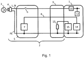
- Fig. 1 shows a schematic representation of a connected to an electric vehicle 1
- Lade einsgarnitur 2 for charging the electric vehicle 1 to a 1-phase household socket 3 with, for example, 230-V or 120-V AC voltage based on the standard IEC 61851-1: 2010.
- the household socket 3 is over an overcurrent protection (for example, a 16-A circuit breaker, not shown) secured and connected to an AC power.
- the charging cord 2 comprises a plug 4, which is connected to the socket 3 for charging.
- the plug 4 provides an outer conductor (phase conductor) L, a neutral conductor N and a protective conductor PE.
- the charging line set 2 further comprises a charging line integrated control device 5.
- the control device 5 comprises a switch 6 (typically a contactor) for switching the mains supply on or off for charging the vehicle. Furthermore, a control circuit 7 is provided, which generates a pulse width modulated (PWM) pilot signal, which is transmitted via a pilot conductor 8 to the vehicle.
- the charging line set further comprises a vehicle clutch 9, which can be connected to a matching charging port of the electric vehicle 1.
- the vehicle coupling 9 is typically a plug.
- the vehicle clutch 9 comprises a proximity resistor 13, the value of which indicates the current-carrying capacity of the charging cable set 2.
- the electric vehicle 1 For charging, the electric vehicle 1 comprises a charger 11, which converts the alternating current into a suitable direct current for charging an electrical energy store 12 of the vehicle 1. Furthermore, the electric vehicle 1 comprises a pilot circuit 14 for receiving the pilot signal via the pilot conductor 8. In addition, the electric vehicle 1 comprises a circuit 15 with which a voltage is applied to the proximity resistor 13, so that the vehicle 1, for example, based on the resulting current can determine the current carrying capacity of the charging cord set 2.
- an automatic charging current reduction is provided after a sudden failure of the mains voltage.
- the vehicle 1 charges with a reduced charging current.
- Two embodiments for implementing this method will be discussed below.
- the reduction of the charging current is caused by the charge line integrated control device 5.
- variable charging current limit for charging the household socket 3 in the vehicle 1, which is stored in the vehicle.
- the variable charging current limit can be changed, for example, by the user via an operating element in the vehicle 1 and corresponds, for example, to a defined proportion of the maximum charging current coded via the pilot signal.
- three stages are provided with 100%, 75% and 50% of the maximum charging current coded via the pilot signal, the preset default value of the charging current limit on delivery of the vehicle 1 being, for example, 75%.
- a 13A maximum charge current encoded via the pilot signal this corresponds to a 9.75A charge current limit.
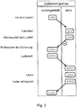
- the pre-charge charging current limit of 9.75A is at the top of the left column in FIG Fig. 2 shown.
- This preset charging current limit can optionally be changed by the user, for example, increased to 100% of the maximum charging current coded via the pilot signal, ie in this case to 13 A (s. Fig. 2 ).
- the vehicle uses the current value (here 13 A) of preset charging current limit as the active charging current limit during the charging process, provided that the minimum of the current signal encoded by the pilot signal and the current carrying capacity through the proximity resistor is less than or equal to a threshold value, for example 15 A. In that case, the vehicle 1 is charged to a household socket accepted.
- a threshold value for example 15 A.
- the active charging current limit of, for example, 13 A is used to limit the charging current. If charging with the active charging current limit without failure of the power supply has been successful, the active charging current limit of, for example, 13 A is adopted as the preset charging current limit. For this purpose, for example, a value of 100% for the preset charging current limit is stored in the vehicle.
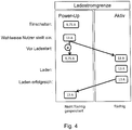
- Fig. 3 shows the situation when recharging in the event that before the end of charging power failure occurs.
- the power failure can be detected, for example, by a current flowing through the proximity resistor and (at the same time) the vehicle no longer receiving a pilot signal.
- a preset charging current limit of 75% 9.75 A, which is used with charging start as active charging current limit for limiting the charging current.
- the vehicle After resetting the overcurrent fuse, the vehicle detects that power is restored (for example, a current flowing through the proximity resistor and the vehicle receiving a pilot signal). If the presence of the power supply is detected and charging is not completed (ie, the charging target has not yet been reached), the charging process with reduced charge current corresponding to the reduced charge current limit is automatically continued without further user intervention.
- the reduced preset charging current limit with charging start is accepted as the active charging current limit for limiting the charging current for the subsequent charging process. If charging with the lower active charging current limit (in this case 9.75 A) has been successful without power failure, the lower active charging current limit of, for example, 9.75 A is adopted as the preset charging current limit.
- a reduced value of, for example, 75% for the preset charging current limit is stored in the vehicle.
- This mechanism of reducing the charging current limit is repeatable several times. For example, the charge current limit is first reduced after a first power failure; after subsequent second failure of the power supply even before the end of the charging process, the charging current limit is further reduced.
- a reduced charging current limit due to a failure of the supply is also preferably used in a new charging process (for example, the next day). A failure of the power supply in the new charging process would then lead to a further reduction of the already reduced charging current limit.
- the maximum current value is preferably newly determined each time from the preset charging current limit, which can then subsequently be used as the current charge current limit.
- the charging current limit can be ignored and the vehicle then draws the minimum from the current limit coded by the pilot signal and the current carrying capacity encoded by the proximity resistor.
- the mechanism is only used when charging via a charging line fitting to a household power outlet (the household power socket charging lines are typically only coded up to 12 A) and not at charging stations and wall boxes supporting 16A and more.
- the charging line set 2, in particular the charging line integrated control unit 5, in this embodiment has an operating element on which the user can set a desired charging current limit.
- a desired charging current limit for example, there are three different settings for the desired charging current limit, for example with 100%, 75% and 50% of the maximum charging current coded on the basis of the pilot signal (in this case 13 A, for example).
- a preset power-up charging current limit is stored, which is available after switching on the control unit 5 (for example, when supplying the charging line integrated control unit 5 with Voltage when plug 4 is plugged into socket 3).
- the power-up charge current limit is stored non-volatile in the charge-line integrated control device 5, for example in a flash memory or in an EEPROM.
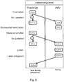
- the power-up charge current limit is in the left column of Fig. 4 shown.
- the stored power-up charging current limit is set at charging start as the active current limit, unless the user changes the charging current.
- the set current limit is non-volatile stored as a power-up charging current limit and also accepted as the active charging current limit.
- the charging line integrated control unit 5 switches the mains voltage to the vehicle 1 by closing the contactor 4.
- the pending charging process is carried out with the active charge current limit (13 A in Fig. 4 ) carried out. If the charging process is terminated without a mains voltage failure, the active current limit is accepted as a power-up current limit and stored in a non-volatile manner.
- Fig. 5 shows the case that a mains voltage failure occurs during charging.
- the power-up charge current limit is - as described above - reduced before charging start (for example, by one stage) and the reduced value stored in a non-volatile manner.
- the power-up charging current limit can be reduced by one level per mains voltage failure.
- the two embodiments described above are extended to the effect that as a further trigger for charging current reduction, the detection of an excess temperature in the plug 4 to the household socket 3 is used when the charging line set 2 is equipped with a corresponding temperature sensor.
- a reduced charging current limit is stored for subsequent charging operations.
Landscapes
- Engineering & Computer Science (AREA)
- Power Engineering (AREA)
- Transportation (AREA)
- Mechanical Engineering (AREA)
- Life Sciences & Earth Sciences (AREA)
- Sustainable Development (AREA)
- Sustainable Energy (AREA)
- Charge And Discharge Circuits For Batteries Or The Like (AREA)
- Electric Propulsion And Braking For Vehicles (AREA)
Description
Die Erfindung betrifft das Laden eines elektrischen Energiespeichers eines Elektrofahrzeugs an einer zur Stromversorgung dienenden Steckdose, insbesondere an einer Haushaltssteckdose.The invention relates to the charging of an electrical energy storage device of an electric vehicle to a power outlet serving for power, in particular to a household socket.
Unter Elektrofahrzeugen wird nachfolgend jedes Fahrzeug verstanden, das von einem Elektromotor angetrieben wird und dessen Elektromotor die elektrische Energie aus einem elektrischen Energiespeicher (beispielsweise einer elektrischen Batterie oder einem elektrischen Kondensator) erhält, der an einer fahrzeugexternen elektrischen Ladequelle ladbar ist, beispielsweise an einer an ein Stromnetz angeschlossenen Haushaltssteckdose. Neben rein elektrisch angetriebenen Elektrofahrzeugen ohne Verbrennungsmotor werden hierunter auch Elektrofahrzeuge mit Range-Extender und Plug-In-Hybrid-Fahrzeuge verstanden.In the following, electric vehicles are understood as meaning any vehicle which is driven by an electric motor and whose electric motor receives the electrical energy from an electrical energy store (for example an electric battery or an electrical capacitor) which can be loaded from an electrical external charging source, for example at a vehicle Mains power connected household socket. In addition to purely electrically driven electric vehicles without combustion engine This also includes electric vehicles with range extender and plug-in hybrid vehicles.
Gewöhnliche 1-phasige Haushaltssteckdosen mit beispielsweise 230-V-Wechselspannung (beispielsweise in Europa) oder 120-V-Wechselspannung (beispielsweise in Nordamerika) können im Unterschied zu Industriesteckdosen, Ladestationen oder Wallboxen meist nur einen geringen maximalen Ladestrom liefern, beispielsweise maximal 16 A. Bei Überschreiten der Strombelastbarkeit spricht typischerweise eine Überstromsicherung an, die den Stromkreis unterbricht.Ordinary 1-phase household sockets with, for example, 230-V AC voltage (for example in Europe) or 120-V AC voltage (for example in North America), in contrast to industrial sockets, charging stations or wall boxes usually provide only a low maximum charging current, for example, a maximum of 16 A. When the current carrying capacity is exceeded, an overcurrent fuse, which interrupts the circuit, typically responds.
In den Normen IEC 61851-1:2010 und SAE-J1772 (Januar 2010) zur Standardisierung des Ladens von Elektrofahrzeugen ist beschrieben, dass der maximale Ladestrom, den das Fahrzeug über die externe Ladequelle beziehen kann, dem Fahrzeug über das Pulsweitenverhältnis des in der Stromversorgungseinrichtung (EV supply equipment) generierten pulsweitenmodulierten Pilotsignals mitgeteilt wird, beispielsweise 13 A bei einem bestimmten Pulsweitenverhältnis. Bei Kenntnis des maximalen Ladestroms (d. h. des verfügbaren Ladestroms) kann das Fahrzeug den tatsächlichen Ladestrom hierauf anpassen.The standards IEC 61851-1: 2010 and SAE-J1772 (January 2010) for standardizing the charging of electric vehicles describes that the maximum charging current which the vehicle can obtain via the external charging source, the vehicle via the pulse width ratio of in the power supply device (EV supply equipment) generated pulse width modulated pilot signal is communicated, for example, 13 A at a certain pulse width ratio. Knowing the maximum charging current (i.e., the available charging current), the vehicle can adjust the actual charging current thereon.
Im Fall des Ladens an einer Steckdose wird das den maximalen Ladestrom angebende Pilotsignal in einem sogenannten ladeleitungsintegrierten Steuergerät (in-cable control box) erzeugt, das Teil der Ladeleitungsgarnitur ist.In the case of charging at a socket, the pilot signal indicating the maximum charging current is generated in a so-called in-cable control box, which is part of the charging cord set.
Gemäß IEC 61851-1:2010 kann durch den Wert eines Widerstands in der Ladeleitungsgarnitur die Strombelastbarkeit der Ladeleitungsgarnitur kodiert werden, beispielsweise 1,5 kΩ bei 13 A Strombelastbarkeit und 220 Ω bei 32 A Strombelastbarkeit. Dieser Widerstand wird auch als Proximity-Widerstand bezeichnet, da dieser sich zwischen dem Annäherungskontakt (Proximity-Kontakt) und dem Erdungskontakt in der Fahrzeugkupplung befindet, die mit dem Fahrzeug verbunden wird.According to IEC 61851-1: 2010, the value of a resistor in the charging cord set can be used to encode the current carrying capacity of the charging cord set, for example 1.5 kΩ at 13 A current-carrying capacity and 220 Ω at 32 A current-carrying capacity. This resistance is also referred to as proximity resistance, since this is between the proximity contact (proximity contact) and the grounding contact is located in the vehicle clutch that is connected to the vehicle.
Es können mit den bislang in den Normen definierten Mechanismen zur Ladestrombegrenzung Ladeleitungsgarnituren für unterschiedliche Haushaltssteckdosentypen mit unterschiedlichen Stromtragfähigkeiten realisiert werden.It can be realized with different Stromtragfähigkeiten Ladeleitungsgarnituren for different types of household sockets with the previously defined in the standards mechanisms for charging current limiting.
Viele Elektrofahrzeuge können mit Hilfe einer mobilen Ladeleitungsgarnitur in an einer Haushaltssteckdose geladen werden, die Teil eines mit einer Überstromsicherung (beispielsweise ein 16-A-Leistungsschutzschalter) gesicherten Stromkreis ist, der neben der elektrischen Last des Fahrzeugs beim Laden des Fahrzeugs durch weitere Verbraucher belastet werden kann.Many electric vehicles can be charged into a household power outlet using a mobile charging line set that is part of a circuit protected by an overcurrent fuse (such as a 16 amp circuit breaker) that is loaded by other loads in addition to the vehicle's electrical load when the vehicle is being charged can.
Es ist dabei nicht vorhersehbar, ob und wann ein Verbraucher neben dem Fahrzeug auf demselben Stromkreis zugeschaltet wird. Wenn bei Zuschalten eines Verbrauchers in dem Stromkreis die Überstromsicherung anspricht, trennt die Überstromsicherung in der Hausinstallation den Stromkreis auf, so dass die Stromversorgung ausfällt und das Laden unterbrochen wird. In umgekehrter Weise kann auch vor Belastung des Stromkreises durch das Elektrofahrzeug bereits eine Belastung des Stromkreises durch einen Verbraucher oder mehrere Verbraucher vorliegen, so dass bei Zuschalten des Elektrofahrzeugs in den Stromkreis zum Laden des Kraftfahrzeugs die Überstromsicherung anspricht und den Stromkreis sofort auftrennt.It is unpredictable whether and when a consumer is connected next to the vehicle on the same circuit. If the overcurrent protection is activated when a consumer is connected to the circuit, the overcurrent fuse in the house installation disconnects the circuit so that the power supply fails and the charging is interrupted. Conversely, even before loading the circuit by the electric vehicle already present a load on the circuit by a consumer or more consumers, so that when switching the electric vehicle in the circuit for charging the motor vehicle, the overcurrent protection responds and disconnects the circuit immediately.
Wird die Trennung an der Überstromsicherung beispielsweise durch Rückstellen eines Leistungsschutzschalters vom Benutzer manuell rückgängig gemacht, wird das Fahrzeug automatisch erneut versuchen mit dem gleichen Ladestrom wie vor dem Ausfall der Stromversorgung das Fahrzeug zu laden und die Überstromsicherung wird erneut den Stromkreis auftrennen. Dieses wiederholte Auslösen der Überstromsicherung in der Hausinstallation kann auf Dauer zu Schädigungen der Elektroinstallation führen. Außerdem bedeutet dies für den Nutzer des Elektrofahrzeugs, dass sein Fahrzeug nicht geladen werden kann, solange der Nutzer keine Veränderung der Belastung des Stromkreises durchführt, beispielsweise durch Entfernen eines Verbrauchers aus dem Stromkreis.If disconnection of the overcurrent fuse is manually reversed by, for example, resetting a circuit breaker by the user, the vehicle will automatically retry charging the vehicle with the same charging current as before the power failure and the overcurrent fuse will again disconnect the circuit. This repeated triggering of the overcurrent fuse in the house installation can lead to permanent damage to the electrical installation to lead. In addition, this means for the user of the electric vehicle that his vehicle can not be charged as long as the user does not change the load on the circuit, for example by removing a consumer from the circuit.
Aus der den nächstliegenden Stand der Technik bildenden Druckschrift
Die Druckschrift
Aus der Druckschrift
Die Druckschrift
Es ist Aufgabe der Erfindung, die vorstehend beschriebenen Nachteile auszuräumen.It is an object of the invention to overcome the disadvantages described above.
Die Aufgabe wird durch die Merkmale der unabhängigen Patentansprüche gelöst. Vorteilhafte Ausführungsformen sind in den abhängigen Ansprüchen beschrieben.The object is solved by the features of the independent claims. Advantageous embodiments are described in the dependent claims.
Ein erster Aspekt der Erfindung betrifft ein Verfahren zum Laden eines elektrischen Energiespeichers eines Elektrofahrzeugs an einer zur Stromversorgung dienenden Steckdose. Das Verfahren wird vorzugsweise zum Laden an einer Haushaltssteckdose, beispielsweise an einer 1-phasigen 230-V- oder 120-V-Haushaltssteckdose, verwendet, da bei Haushaltssteckdosen die Überstromsicherung bereits bei geringen Ladeströmen anspricht, beispielsweise ab ca. 14 A Dauerstrom (eine Sicherung mit 16 A Nominalwert kann bereits schon ca. 10 % unter halb ihres Normalwerts auslösen, wenn eine Dauerlast besteht) . Grundsätzlich könnte die Erfindung aber auch beim Laden an höher abgesicherten Industriesteckdosen verwendet werden.A first aspect of the invention relates to a method for charging an electrical energy storage device of an electric vehicle at a power supply socket. The method is preferably used for charging to a household socket, for example, a single-phase 230V or 120V household socket, as in household sockets the overcurrent protection responds even at low charging currents, for example, from about 14 A continuous current (a fuse with 16 A nominal value can already trigger about 10% below half of its normal value, if a permanent load exists). In principle, however, the invention could also be used when charging at higher-protected industrial sockets.
Der Energiespeicher des Fahrzeugs wird beispielsweise schon über einen gewissen Zeitraum geladen und durch Zuschalten eines weiteren Verbrauchers wird eine Überstromsicherung ausgelöst, so dass es zu einem Ausfall der Stromversorgung kommt. Alternativ wird beispielsweise unmittelbar nach Ladestart eine Überstromsicherung ausgelöst, wenn beispielsweise der Stromkreis bereits durch einen oder mehrere Verbraucher belastet war.The energy storage of the vehicle, for example, already charged for a certain period of time and by connecting another consumer an overcurrent protection is triggered, so there is a failure of the power supply. Alternatively, for example, immediately after charging start an overcurrent protection is triggered when, for example, the circuit was already burdened by one or more consumers.
Gemäß dem erfindungsgemäßen Verfahren wird nach Ausfall der Stromversorgung und anschließendem Wiedereinsetzen der Stromversorgung ein Ladestrom zum Laden des elektrischen Energiespeichers verwendet, der gegenüber dem Ladestrom vor Ausfall der Stromversorgung automatisch reduziert ist, beispielsweise um 10% oder mehr.According to the inventive method, a charging current for charging the electrical energy storage is used after failure of the power supply and subsequent re-insertion of the power supply, which is automatically reduced compared to the charging current before power failure, for example by 10% or more.
Erfindungsgemäß wird also eine automatische Ladestromreduzierung nach einem plötzlichen Ausfall der Stromversorgung vorgeschlagen. Wenn der Ladevorgang nach dem Wiedereinsetzen der Stromversorgung wieder gestartet wird, so lädt das Fahrzeug mit reduziertem Ladestrom.Thus, according to the invention, an automatic charging current reduction is proposed after a sudden failure of the power supply. If the charging process is restarted after the power is restored, the vehicle will charge with reduced charging current.
Durch das erfindungsgemäße Verfahren kann ein Ladevorgang nach Ansprechen und anschließendem Rücksetzen der Überstromsicherung in der Hausinstallation fortgesetzt werden, ohne dass die Überstromsicherung erneut auslöst. Der Ladevorgang kann dabei nach Wiedereinsetzen der Stromversorgung vom Fahrzeug automatisch ohne weiteres Zutun des Benutzers fortgesetzt werden. Eine Schädigung der Hauselektroinstallation durch wiederholtes Auslösen der Überstromsicherung in der Hauselektroinstallation wird vermieden. Außerdem ermöglicht die Erfindung ein Laden an einem durch andere elektrische Verbraucher belasteten Stromkreis oder an einem schwach abgesicherten Stromkreis, ohne dass der Benutzer eine Veränderung in der Belastung des Stromkreises durchführen muss, beispielsweise durch Entfernen eines Verbrauchers aus dem Stromkreis. Ein Nutzer, der sich nicht mit der Stromtragfähigkeit der Hausinstallation oder etwaiger Ladestromeinstellungen beschäftigen will, wird unterstützt, da der Ladestrom automatisch angepasst wird.By means of the method according to the invention, a charging process can be continued after the response and subsequent resetting of the overcurrent protection in the house installation without the overcurrent protection being triggered again. The charging process can be continued automatically after reinserting the power supply from the vehicle without further action by the user. Damage to the house electrical installation by repeatedly triggering the overcurrent protection in the house electrical installation is avoided. In addition, the invention allows charging on a circuit loaded by other electrical loads or on a fused circuit without the user having to make a change in the load on the circuit, for example by removing a load from the circuit. A user who does not want to deal with the current carrying capacity of the house installation or any charging current settings is supported because the charging current is adjusted automatically.
Darüber hinaus vermindert das erfindungsgemäße Verfahren die verstärkte Abnutzung von Haushaltssteckdosen und des Steckers der Ladeleitungsgarnitur, die entsteht, wenn während des Ladevorgangs zuerst der Stecker der Ladeleitungsgarnitur an der Steckdose und nicht die Fahrzeugkupplung der Ladeleitungsgarnitur vom Stromanschluss des Fahrzeugs abgezogen wird. Das Abziehen des Steckers von der Steckdose kann als Ausfall der Stromversorgung interpretiert werden, so dass für einen späteren Ladeprozess ein reduzierter Ladestrom verwendet wird. Um eine Reduktion des Ladestroms zu verhindern, wird der Nutzer die Fahrzeugkupplung der Ladeleitungsgarnitur zuerst lösen, wobei dies im Allgemeinen nur möglich ist, wenn eine Entriegelung betätigt wird, die gleichzeitig das Laden beendet, so dass die Stromversorgungskontakte der Fahrzeugkupplung der Ladeleitungsgarnitur beim Lösen im Wesentlichen stromlos sind.In addition, the inventive method reduces the increased wear of household sockets and the plug of the charging line set, which arises when charging the first the plug of the charging cord set at the socket and not the The vehicle coupling of the charging line set is disconnected from the power connection of the vehicle. The removal of the plug from the socket can be interpreted as a failure of the power supply, so that for a later charging process, a reduced charging current is used. In order to prevent a reduction of the charging current, the user will first release the vehicle coupling of the charging cord set, which is generally possible only when a release is actuated which simultaneously terminates the charging, so that the power supply contacts of the vehicle coupling of the charging cord set during release substantially are de-energized.
Vorzugsweise wird vor Ausfall der Stromversorgung und nach Wiedersetzen der Stromversorgung der Ladestrom jeweils nach oben durch eine aktive Ladestromgrenze begrenzt. Das erfindungsgemäße Verfahren sieht hierbei vor, dass die aktive Ladestromgrenze nach Wiedereinsetzen der Stromversorgung kleiner als die aktive Ladestromgrenze vor Ausfall der Stromversorgung ist, insbesondere um mindestens 10 % kleiner. Die aktive Ladestromgrenze wird beispielsweise von ungefähr 13 A auf ungefähr 10 A reduziert.Preferably, prior to failure of the power supply and after resetting the power supply, the charging current is limited in each case upward by an active charging current limit. The inventive method provides in this case that the active charging current limit after reinsertion of the power supply is smaller than the active charging current limit before failure of the power supply, in particular by at least 10% smaller. For example, the active charging current limit is reduced from about 13 amps to about 10 amps.
Der Mechanismus zur automatischen Ladestromreduzierung kann beispielsweise im Fahrzeug oder alternativ in dem ladeleitungsintegrierten Steuergerät der Ladeleitungsgarnitur umgesetzt werden.The mechanism for automatic charging current reduction can be implemented, for example, in the vehicle or alternatively in the charging line integrated control unit of Ladeleitungsgarnitur.
Bei einer Ausführungsform des erfindungsgemäßen Verfahrens wird der Mechanismus zur Ladestromreduzierung im Fahrzeug umgesetzt, d. h. die Reduktion des Ladestroms wird seitens des Fahrzeugs hervorgerufen. Hierzu ist vorgesehen, dass vor Ausfall der Stromversorgung im Fahrzeug eine variable Ladestromgrenze zur Begrenzung des Ladestroms nach oben für das Laden an Haushaltssteckdosen vorliegt. Die variable Ladestromgrenze kann beispielsweise vom Nutzer über eine Bedienelement im Fahrzeug verändert werden und entspricht beispielsweise einem definierten Anteil des über das Pilotsignal kodierten maximalen Ladestroms, beispielsweise eine variable Ladestromgrenze mit mehreren Stufen, beispielsweise drei Stufen mit 100 %, 75 % und 50 % des über das Pilotsignal kodierten maximalen Ladestroms. Falls beim Laden vor Ladeende ein Ausfall der Stromversorgung auftritt, reduziert das Fahrzeug automatisch die Ladestromgrenze, beispielsweise wird bei einer mehrstufig einstellbaren Ladestromgrenze die Ladestromgrenze um eine Stufe reduziert (beispielsweise von 100 % des maximalen Ladestroms auf 75 % des maximalen Ladestroms).In one embodiment of the method according to the invention, the mechanism for charging current reduction in the vehicle is implemented, ie the reduction of the charging current is caused by the vehicle. For this purpose, it is provided that prior to failure of the power supply in the vehicle, a variable charging current limit for limiting the charging current upwards for charging to household sockets exists. The variable charging current limit can be changed, for example, by the user via an operating element in the vehicle and corresponds, for example, to one defined proportion of the coded via the pilot signal maximum charging current, for example, a variable charging current limit with multiple stages, for example, three stages with 100%, 75% and 50% of the coded via the pilot signal maximum charging current. If charging fails before the end of charging, the vehicle will automatically reduce the charging current limit; for example, the charging current limit will be reduced by one step (for example from 100% of the maximum charging current to 75% of the maximum charging current) for a multi-stage adjustable charging current limit.
Nach Wiedereinsetzen der Stromversorgung wird dann der Ladevorgang mit reduziertem Ladestrom entsprechend der reduzierten Ladestromgrenze durchgeführt (sofern der Ladevorgang noch nicht beendet war).After the power supply has been replaced, the charging process is then carried out with a reduced charging current corresponding to the reduced charging current limit (provided that the charging process had not yet been completed).
Die reduzierte Ladestromgrenze kann im Fahrzeug gespeichert werden, so dass diese vorzugsweise nach Benutzung des Fahrzeugs bei einem neuen Ladevorgang (beispielsweise am nächsten Tag) zur Begrenzung des Ladestroms herangezogen wird.The reduced charge current limit can be stored in the vehicle so that it is preferably used after the use of the vehicle in a new charge (for example, the next day) to limit the charging current.
Die Ladestromgrenze wird bei dieser Ausführungsform nach Ausfall der Stromversorgung vom Fahrzeug reduziert. Das Fahrzeug kann beispielsweise den Ausfall der Stromversorgung zum Auslösen der Reduktion der Ladestromgrenze erkennen und bei Erkennen des Ausfalls die Ladestromgrenze reduzieren. Der Ausfall der Stromversorgung kann beispielsweise an dem Vorliegen zweier Bedingungen festgemacht werden: Erstens liegt ein entsprechendes Signal im den Annäherungskontakt umfassenden Annäherungsstromkreis vor, welches eine bestehende Verbindung der Fahrzeugkopplung der Ladeleitungsgarnitur mit dem Fahrzeug anzeigt (es fließt beispielsweise ein bestimmter Strom über den Proximity-Widerstand am Annäherungskontakt). Zweitens wird vom Fahrzeug kein Pilotsignal mehr erkannt.The charging current limit is reduced in this embodiment after failure of the power supply from the vehicle. The vehicle can detect, for example, the failure of the power supply to trigger the reduction of the charging current limit and reduce the charging current limit when detecting the failure. The failure of the power supply can be fixed, for example, to the presence of two conditions: first, there is a corresponding signal in the proximity contact circuit comprising the proximity circuit indicating an existing connection of the vehicle coupling of the charging line to the vehicle (for example, a certain current is flowing through the proximity resistor at the proximity contact). Second, the vehicle no longer detects a pilot signal.
Die Reduktion der Ladestromgrenze kann wiederholt werden, auch mehrmals. So wird die Ladestromgrenze beispielsweise nach einem ersten Ausfall der Stromversorgung ein erstes Mal reduziert, nach Fortführung des Ladeprozesses und anschließendem zweiten Ausfall der Stromversorgung noch vor Beendigung des Ladeprozesses wird die Ladestromgrenze noch weiter reduziert. Außerdem wird eine aufgrund eines Ausfalls der Versorgung reduzierte Ladestromgrenze vorzugsweise auch bei einem neuen Ladeprozess (beispielsweise am nächsten Tag) verwendet. Ein Ausfall der Stromversorgung bei dem neuen Ladeprozess würde dann zu einer weiteren Reduktion der bereits reduzierten Ladestromgrenze führen.The reduction of the charging current limit can be repeated, even several times. For example, the charge current limit is reduced for the first time after a first power failure, and after the charging process has continued and the power fails, the charging current limit is reduced even further before the charging process is completed. In addition, a reduced charging current limit due to a failure of the supply is also preferably used in a new charging process (for example, the next day). A failure of the power supply in the new charging process would then lead to a further reduction of the already reduced charging current limit.
Vorzugsweise verwendet das Fahrzeug eine im Fahrzeug vorliegende Ladestromgrenze zum Begrenzen des Ladestroms nur, wenn seitens des Fahrzeugs erkannt wird, dass das Fahrzeug an einer Haushaltssteckdose und nicht an einer Ladestation oder einer sogenannten Wallbox geladen wird. Hierzu wird beispielsweise geprüft, ob der verfügbare Ladestrom kleiner als oder kleiner gleich einem Schwellwert ist, beispielsweise kleiner gleich einem Schwellwert von ungefähr 15 A (der beispielhafte Schwellwert von 15 A ist vor dem Hintergrund sinnvoll, dass die verwendbaren Ladeleitungsgranituren für Haushaltssteckedose im Allgemeinen mit 12 A als verfügbaren Ladestrom kodiert sind). Dazu kann beispielsweise der durch das Pilotsignal kodierte maximale Ladestrom und optional die durch den Proximity-Widerstand definierte Strombelastbarkeit ausgewertet werden. Beispielsweise beachtet das Fahrzeug die Ladestromgrenze, sofern der über das Pilotsignal definierte maximale Ladestrom und die über den Proximity-Widerstand kodierte Strombelastbarkeit kleiner oder gleich einem Schwellwert von ungefähr 15 A sind, da dies auf das Laden an einer Haushaltssteckdose hindeutet.Preferably, the vehicle uses a charging current limit in the vehicle for limiting the charging current only when it is detected by the vehicle that the vehicle is being charged at a household socket and not at a charging station or a so-called wallbox. For this purpose, for example, it is checked whether the available charging current is less than or equal to a threshold value, for example less than a threshold value of about 15 A (the exemplary threshold of 15 A is useful against the background that the usable charging line grids for household socket generally with 12 A are encoded as available charging current). For this purpose, for example, the maximum charging current coded by the pilot signal and optionally the current-carrying capacity defined by the proximity resistor can be evaluated. For example, the vehicle observes the charging current limit, as long as the maximum charge current defined via the pilot signal and the current carrying capacity encoded via the proximity resistor are less than or equal to a threshold of approximately 15 A, as this indicates charging at a household socket.
Vorzugsweise wird eine bereits vorher reduzierte Ladestromgrenze bei einem erneuten Ladevorgang nicht zur Begrenzung des Ladestroms unter der Voraussetzung verwendet, wenn das Fahrzeug nicht an einer Haushaltssteckdose geladen wird (sondern beispielsweise an einer Ladestation oder einer sogenannten Wallbox). Hierzu wird beispielsweise geprüft, ob der verfügbare Ladestrom der Stromversorgung größer oder größer gleich einem Schwellwert ist, wobei dies insbesondere anhand des empfangenen Pilotsignals seitens des Fahrzeugs erkannt wird. Beispielsweise wird eine bereits in einem vorherigen Ladevorgang reduzierte Ladestromgrenze bei einem erneuten Ladevorgang ignoriert, sofern der über das Pilotsignal definierte maximale Ladestrom und optional auch der über den Proximity-Widerstand kodierte Strombelastbarkeit größer einem Schwellwert von beispielsweise ungefähr 15 A sind. In diesem Fall wird der Ladestrom durch eine aktive Ladestromgrenze begrenzt, die dem Minimum aus dem über das Pilotsignal definierten maximale Ladestrom und der über den Proximity-Widerstand kodierten Strombelastbarkeit entspricht.Preferably, an already previously reduced charging current limit is not used in a recharging process to limit the charging current, provided that the vehicle is not at a Household socket is loaded (but for example at a charging station or a so-called wallbox). For this purpose, for example, it is checked whether the available charging current of the power supply is greater than or equal to a threshold value, this being detected in particular on the basis of the received pilot signal from the side of the vehicle. For example, a charge current limit which has already been reduced in a previous charging process is ignored during a renewed charging process, provided that the maximum charging current defined via the pilot signal and optionally also the current-carrying capacity coded via the proximity resistor are greater than a threshold value of, for example, approximately 15 A. In this case, the charging current is limited by an active charging current limit which corresponds to the minimum of the maximum charging current defined via the pilot signal and the current-carrying capacity coded via the proximity resistor.
Bei einer weiteren Ausführungsform des erfindungsgemäßen Verfahrens wird der Mechanismus zur Ladestromreduzierung nach einem Ausfall der Stromversorgung in dem ladeleitungsintegrierten Steuergerät der Ladeleitungsgarnitur umgesetzt, d. h. die Reduktion des Ladestroms wird seitens eines ladeleitungsintegrierten Steuergerät der Ladeleitungsgarnitur hervorgerufen.In a further embodiment of the method according to the invention, the mechanism for charging current reduction is implemented after a failure of the power supply in the charging line integrated control unit of the charging line fitting, d. H. the reduction of the charging current is caused by a charging line integrated control unit of the charging line set.
Hierzu ist vorgesehen, dass vor Ausfall der Stromversorgung eine reduzierte Ladestromgrenze zur Begrenzung des Ladestroms in dem ladeleitungsintegrierten Steuergerät gespeichert wird, welcher gegenüber der aktiven Ladestromgrenze vor Ausfall der Stromversorgung des Kraftfahrzeugs reduziert ist. Es wird also eine Ladestromgrenze gespeichert, die geringer als die Ladestromgrenze ist, die bis zum Ausfall der Stromversorgung zum Begrenzen des Ladestroms nach oben verwendet wird. Nach Wiedereinsetzen der Stromversorgung wird dann die gespeicherte reduzierte Ladestromgrenze als aktive Ladestromgrenze zur Begrenzung des Ladestroms verwendet.For this purpose, it is provided that prior to failure of the power supply, a reduced charging current limit for limiting the charging current is stored in the charge-line integrated control device, which is reduced compared to the active charging current limit before failure of the power supply of the motor vehicle. Thus, a charge current limit is stored which is less than the charge current limit used until the power supply fails to limit the charging current up. After resuming the power supply, the stored reduced charging current limit is then used as the active charging current limit for limiting the charging current.
Der Hintergrund für das frühzeitige Abspeichern einer reduzierten Ladestromgrenze (beispielsweise noch bevor das Laden des Fahrzeugs beginnt) liegt darin, dass mit Ausfall der Stromversorgung das ladeleitungsintegrierte Steuergerät auch nicht mehr mit Strom versorgt wird (da es typischerweise keine eigene Stromversorgung ausweist) und somit auf den Ausfall nicht mehr durch Reduktion der Ladestromgrenze reagieren kann.The background for the early storage of a reduced charge current limit (for example, even before the charging of the vehicle begins) is that with failure of the power supply, the charging line integrated control unit is no longer supplied with power (since it typically does not have its own power supply) and thus on the Failure can no longer respond by reducing the charging current limit.
Die Ladestromgrenze wird vorzugsweise in nicht-flüchtiger Weise mittels eines nicht-flüchtigen Speichers in dem Steuergerät gespeichert, beispielsweise mit einem Flash-Speicher oder einem EEPROM (electrically erasable programmable read-only memory). Durch das nicht-flüchtige Speichern der Ladestromgrenze bleibt die gespeicherte Ladestromgrenze auf Dauer erhalten, also auch wenn der Stecker der Ladeleitung mit dem ladeleitungsintegrierten Steuergerät von der Haushaltssteckdose getrennt wird und damit nicht mehr mit Strom versorgt wird.The charging current limit is preferably stored in a non-volatile manner by means of a non-volatile memory in the control unit, for example with a flash memory or an EEPROM (electrically erasable programmable read-only memory). Due to the non-volatile storage of the charging current limit, the stored charge current limit is maintained over time, so even if the plug of the charging line with the charging line integrated control unit is disconnected from the household socket and thus no longer supplied with power.
Eine reduzierte Ladestromgrenze wird vorzugsweise abgespeichert, nachdem das Fahrzeug die Bereitschaft zum Laden signalisiert und bevor das Laden des Fahrzeugs beginnt. Zum Signalisieren der Bereitschaft zum Laden wird gemäß IEC 61851-1:2010 ein Schalter im Ladeinterface des Fahrzeugs geschlossen, so dass der High-Pegel des Pilotsignals von +9 V auf +6 V abfällt. Dieser Pegelabfall kann seitens des Steuergeräts erkannt werden und dann eine reduzierte Ladestromgrenze abgespeichert werden, die dann nach Stromausfall und anschließendem Wiedereinsetzen der Stromversorgung zur Begrenzung des Ladestroms verwendet wird.A reduced charging current limit is preferably stored after the vehicle signals the readiness to charge and before charging of the vehicle begins. To signal the readiness for charging, according to IEC 61851-1: 2010, a switch in the charging interface of the vehicle is closed so that the high level of the pilot signal drops from +9 V to +6 V. This level drop can be detected by the controller and then stored a reduced charging current limit, which is then used after power failure and then re-insertion of the power supply to limit the charging current.
Der Ladevorgang wird mit einer aktiven Stromgrenze (beispielsweise 13 A) durchgeführt, die größer als die gespeicherte reduzierte Stromgrenze (beispielsweise 10 A) ist. Wenn der Ladevorgang beendet wird, ohne dass ein Netzspannungsausfall auftritt, dann wird die aktive Stromgrenze als Ladestromgrenze übernommen und in dem Steuergerät gespeichert. Hierbei wird die vorzugsweise vor Ladebeginn abgespeicherte reduzierte Ladestromgrenze überschrieben. Wenn aber während des Ladens ein Netzspannungsausfall auftritt, wird der Ladevorgang nach Wiederherstellung der Stromversorgung mir reduziertem Ladestrom vorgenommen, da nach einem Einschalten des Steuergeräts die abgespeicherte reduzierte Stromgrenze als aktive Stromgrenze übernommen wird.The charging process is performed with an active current limit (for example 13 A) which is greater than the stored reduced current limit (for example 10 A). If the charging process is terminated without a mains voltage failure occurs, then the active current limit is accepted as the charging current limit and stored in the controller. in this connection the overwritten preferably before loading start reduced charge current limit is overwritten. However, if a mains voltage failure occurs during charging, the charging process is carried out after the power supply has been restored with a reduced charging current, since the stored reduced current limit is adopted as the active current limit after switching on the control unit.
Es ist von Vorteil, wenn die Ladestromgrenze über ein Bedienelement der Ladeleitungsgarnitur vom Benutzer einstellbar ist und diese bei Lösen der Ladeleitungsgarnitur von der Haushaltssteckdose beibehalten bleibt. Die eingestellte Ladestromgrenze wird als aktive Ladestromgrenze zur Begrenzung des Ladestroms beim Ladevorgang übernommen.It is advantageous if the charging current limit is adjustable by the user via a control element of the charging line set and this is maintained when the charging line set is detached from the household socket. The set charging current limit is accepted as the active charging current limit for limiting the charging current during the charging process.
Ein zweiter Aspekt der Erfindung ist auf ein Elektrofahrzeug mit einem elektrischen Energiespeicher gerichtet, welcher über ein im Fahrzeug integriertes Ladegerät an einer zur Stromversorgung dienenden Haushaltssteckdose ladbar ist. Das Fahrzeug weist eine variable Ladestromgrenze zur Begrenzung des Ladestroms nach oben auf; die Ladestromgrenze ist vorzugsweise vom Nutzer veränderbar. Das Fahrzeug ist eingerichtet, die Ladestromgrenze nach Ausfall der Stromversorgung automatisch zu reduzieren.A second aspect of the invention is directed to an electric vehicle with an electrical energy storage, which can be loaded via a charger integrated in the vehicle to a household socket serving for the power supply. The vehicle has a variable charging current limit for limiting the charging current to the top; the charging current limit is preferably changeable by the user. The vehicle is set up to automatically reduce the charging current limit after power failure.
Die vorstehenden Ausführungen zum erfindungsgemäßen Verfahren nach dem ersten Aspekt der Erfindung gelten in entsprechender Weise auch für das erfindungsgemäße Elektrofahrzeug nach dem zweiten Aspekt der Erfindung. An dieser Stelle nicht explizit beschriebene vorteilhafte Ausführungsbeispiele des erfindungsgemäßen Elektrofahrzeugs entsprechen den beschriebenen vorteilhaften Ausführungsbeispielen des erfindungsgemäßen Verfahrens.The above statements on the method according to the invention according to the first aspect of the invention also apply correspondingly to the electric vehicle according to the invention according to the second aspect of the invention. At this point not explicitly described advantageous embodiments of the electric vehicle according to the invention correspond to the described advantageous embodiments of the method according to the invention.
Ein dritter Aspekt der Erfindung ist auf ein Steuergerät für eine Ladeleitungsgarnitur gerichtet. Das Steuergerät ist eingerichtet, bereits vor Ausfall der Stromversorgung eine reduzierte Ladestromgrenze zur Begrenzung des Ladestroms in insbesondere nicht-flüchtiger Weise zu speichern, welcher gegenüber einer zum Laden aktiven Ladestromgrenze zur Begrenzung des Ladestroms vor Ausfall der Stromversorgung reduziert ist, so dass für das Laden nach Wiedereinsetzen der Stromversorgung die gespeicherte reduzierte Ladestromgrenze zur Begrenzung des Ladestroms verwendet wird. Hierzu wird vorzugsweise die gespeicherte Stromgrenze als aktive Stromgrenze übernommen und dem Fahrzeug seitens des Steuergeräts über das Pilotsignal mitgeteiltA third aspect of the invention is directed to a charging line control unit. The control unit is set up already before Failure of the power supply to save a reduced charging current limit for limiting the charging current in particular non-volatile manner, which is reduced compared to a charging active charging current limit for limiting the charging current before power failure, so that for charging after reinserting the power supply, the stored reduced charging current limit is used to limit the charging current. For this purpose, the stored current limit is preferably taken over as the active current limit and communicated to the vehicle by the control unit via the pilot signal
Die vorstehenden Ausführungen zum erfindungsgemäßen Verfahren nach dem ersten Aspekt der Erfindung gelten in entsprechender Weise auch für das Steuergerät nach dem dritten Aspekt der Erfindung. An dieser Stelle nicht explizit beschriebene vorteilhafte Ausführungsbeispiele des erfindungsgemäßen Steuergeräts entsprechen den beschriebenen vorteilhaften Ausführungsbeispielen des erfindungsgemäßen Verfahrens.The above statements on the method according to the invention according to the first aspect of the invention also apply correspondingly to the control device according to the third aspect of the invention. At this point, not explicitly described advantageous embodiments of the control device according to the invention correspond to the described advantageous embodiments of the method according to the invention.
Die Erfindung wird nachfolgend unter Zuhilfenahme auf die beigefügten Zeichnungen anhand mehrerer Ausführungsbeispiele beschrieben. In diesen zeigen:
- Fig. 1
- eine mit einem Elektrofahrzeug verbundene Ladeleitungsgarnitur zum Laden des Elektrofahrzeugs an einer Haushaltssteckdose;
- Fig. 2, Fig. 3
- ein erstes Ausführungsbeispiel des erfindungsgemäßen Verfahrens, wobei die Reduktion des Ladestroms seitens des Fahrzeugs hervorgerufen wird; und
- Fig. 4, Fig. 5
- ein zweites Ausführungsbeispiel des erfindungsgemäßen Verfahrens, wobei die Reduktion des Ladestroms seitens des ladeleitungsintegrierten Steuergeräts hervorgerufen wird.
- Fig. 1
- a charge cord assembly connected to an electric vehicle for charging the electric vehicle to a household power outlet;
- Fig. 2, Fig. 3
- a first embodiment of the method according to the invention, wherein the reduction of the charging current is caused by the vehicle; and
- Fig. 4, Fig. 5
- A second embodiment of the method according to the invention, wherein the reduction of the charging current caused by the charge line integrated control device.
Zum Laden umfasst das Elektrofahrzeug 1 ein Ladegerät 11, welches den Wechselstrom in einen passenden Gleichstrom zum Laden eines elektrischen Energiespeichers 12 des Fahrzeugs 1 wandelt. Ferner umfasst das Elektrofahrzeug 1 eine Pilotschaltung 14 zum Empfang des Pilotsignals über den Pilotleiter 8. Darüber hinaus umfasst das Elektrofahrzeug 1 eine Schaltung 15, mit der eine Spannung auf den Proximity-Widerstand 13 geführt wird, damit das Fahrzeug 1 beispielsweise anhand des resultierenden Stroms die Strombelastbarkeit der Ladeleitungsgarnitur 2 feststellen kann.For charging, the
Erfindungsgemäß wird eine automatische Ladestromreduzierung nach einem plötzlichen Ausfall der Netzspannung vorgesehen. Wenn ein Ladevorgang nach einem Netzspannungsausfall fortgesetzt wird, lädt das Fahrzeug 1 mit reduziertem Ladestrom. Nachfolgend werden zwei Ausführungsformen zur Umsetzung dieses Verfahrens diskutiert. Bei dem anhand von
Bei dem ersten Ausführungsbeispiel zur Umsetzung des Verfahrens im Fahrzeug 1 liegt im Fahrzeug eine variable voreingestellte Ladestromgrenze für das Laden an der Haushaltssteckdose 3 im Fahrzeug 1 vor, die im Fahrzeug gespeichert ist. Die variable Ladestromgrenze kann beispielsweise vom Nutzer über ein Bedienelement im Fahrzeug 1 verändert werden und entspricht beispielsweise einem definierten Anteil des über das Pilotsignal kodierten maximalen Ladestroms. Beispielsweise sind drei Stufen mit 100 %, 75 % und 50 % des über das Pilotsignal kodierten maximalen Ladestroms vorgesehen, wobei der voreingestellte Default-Wert der Ladestromgrenze bei Auslieferung des Fahrzeugs 1 beispielsweise 75% ist. Bei einem über das Pilotsignal kodierten maximalen Ladestrom von beispielsweise 13 A entspricht dies einer Ladestromgrenze von 9,75 A. Die voreingestellte Ladestromgrenze von 9,75 A vor dem Laden ist oben in der linken Spalte in
Diese voreingestellte Ladestromgrenze kann wahlweise vom Nutzer verändert werden, beispielsweise auf 100 % des über das Pilotsignal kodierten maximalen Ladestroms erhöht werden, d. h. in diesem Fall auf 13 A (s.
Falls beim Laden vor Ladeende ein Netzspannungsausfall auftritt, reduziert das Fahrzeug sofort nach Erkennen des Stromausfalls die voreingestellte Stromgrenze, indem es diese beispielsweise eine Stufe zurückstellt, d. h. von 100 % = 13 A auf 75 % = 9,75 A. Diese Reduktion ist in
Dieser Mechanismus der Reduktion der Ladestromgrenze ist mehrfach wiederholbar. So wird die Ladestromgrenze beispielsweise nach einem ersten Ausfall der Stromversorgung ein erstes Mal reduziert; nach anschließendem zweiten Ausfall der Stromversorgung noch vor Beendigung des Ladeprozesses wird die Ladestromgrenze noch weiter reduziert. Außerdem wird eine aufgrund eines Ausfalls der Versorgung reduzierte Ladestromgrenze vorzugsweise auch bei einem neuen Ladeprozess (beispielsweise am nächsten Tag) verwendet. Ein Ausfall der Stromversorgung bei dem neuen Ladeprozess würde dann zu einer weiteren Reduktion der bereits reduzierten Ladestromgrenze führen.This mechanism of reducing the charging current limit is repeatable several times. For example, the charge current limit is first reduced after a first power failure; after subsequent second failure of the power supply even before the end of the charging process, the charging current limit is further reduced. In addition, a reduced charging current limit due to a failure of the supply is also preferably used in a new charging process (for example, the next day). A failure of the power supply in the new charging process would then lead to a further reduction of the already reduced charging current limit.
Bei Ladebeginn und bei jeder Änderung des Pulsweitenverhältnisses im Pilotsignal wird vorzugsweise jedes Mal der maximale Stromwert aus der voreingestellten Ladestromgrenze neu bestimmt, der dann anschließend als Stromwert für die aktiven Ladestromgrenze verwendet werden kann.At the start of charging and with each change in the pulse width ratio in the pilot signal, the maximum current value is preferably newly determined each time from the preset charging current limit, which can then subsequently be used as the current charge current limit.
Sofern das Minimum aus der durch das Pilotsignal kodierten Stromgrenze und der durch den Proximity-Widerstand kodierten Stromtragfähigkeit den Schwellwert von hier 15 A überschreitet, kann die Ladestromgrenze ignoriert werden und das Fahrzeug zieht als aktive Stromgrenze dann das Minimum aus der durch das Pilotsignal kodierten Stromgrenze und der durch den Proximity-Widerstand kodierten Stromtragfähigkeit heran. Dadurch wird erreicht, dass der Mechanismus nur beim Laden über eine Ladeleitungsgarnitur an einer Haushaltssteckdose verwendet wird (die Ladeleitungsgarnituren für Haushaltssteckdosen sind typischerweise nur bis 12 A kodiert) und nicht bei Ladestationen und Wallboxen, die 16A und mehr unterstützen.If the minimum of the current limit coded by the pilot signal and the current carrying capacity coded by the proximity resistor exceeds the threshold value of 15 A here, the charging current limit can be ignored and the vehicle then draws the minimum from the current limit coded by the pilot signal and the current carrying capacity encoded by the proximity resistor. As a result, the mechanism is only used when charging via a charging line fitting to a household power outlet (the household power socket charging lines are typically only coded up to 12 A) and not at charging stations and wall boxes supporting 16A and more.
Anhand von
Die Ladeleitungsgarnitur 2, insbesondere das ladeleitungsintegrierte Steuergerät 5, verfügt bei diesem Ausführungsbeispiel über ein Bedienelement an dem der Benutzer eine gewünschte Ladestromgrenze einstellen kann. Beispielsweise gibt es hierfür drei verschiedene Einstellungen für die gewünschte Ladestromgrenze, beispielsweise mit 100 %, 75 % und 50 % des anhand des Pilotsignals kodierten maximalen Ladestroms (hier beispielsweise 13 A). In dem ladeleitungsintegrierten Steuergeräts 5 ist eine voreingestellten Power-Up-Ladestromgrenze gespeichert, die nach Einschalten des Steuergeräts 5 zur Verfügung steht (beispielsweise bei Versorgen des ladeleitungsintegrierten Steuergeräts 5 mit Spannung, wenn der Stecker 4 in die Steckdose 3 gesteckt wird). Die Power-Up-Ladestromgrenze wird nicht-flüchtig in dem ladeleitungsintegrierten Steuergerät 5 gespeichert, beispielsweise in einem Flash-Speicher oder in einem EEPROM. Die Power-Up-Ladestromgrenze ist in der linken Spalte von
Nach dem Einschalten des ladeleitungsintegrierten Steuergeräts 5 wird die abgespeicherte Power-Up-Ladestromgrenze bei Ladestart als aktive Stromgrenze eingestellt, sofern der Benutzer den Ladestrom nicht ändert. Der Benutzer kann nach dem Einschalten des ladeleitungsintegrierten Steuergeräts 5 (zum Beispiel durch Anstecken der Ladeleitungsgarnitur 2 an der Haushaltssteckdose 3) und vor Beginn des Ladevorgangs (d.h. vor Anstecken der Ladeleitungsgarnitur 2 am Fahrzeug1) die Stromgrenze am Bedienelement einstellen (beispielsweise 13 A = 100 % in
Danach schaltet das ladeleitungsintegrierte Steuergerät 5 durch Schließen des Schützes 4 die Netzspannung zum Fahrzeug 1 durch. Der anstehende Ladevorgang wird mit der aktiven Ladestromgrenze (13 A in
Bei wiederholten Netzspannungsausfällen kann die Power-Up-Ladestromgrenze jeweils pro Netzspannungsausfall um eine Stufe reduziert werden.In the event of repeated mains power failures, the power-up charging current limit can be reduced by one level per mains voltage failure.
Der vorstehend in Zusammenhang mit
Optional kann vorgesehen sein, dass die beiden vorstehend beschriebenen Ausführungsbeispiele dahingehend erweitert sind, dass als weiterer Trigger zur Ladestromreduzierung das Erkennen einer Übertemperatur im Stecker 4 zur Haushaltssteckdose 3 verwendet wird, wenn die Ladeleitungsgarnitur 2 mit einem entsprechenden Temperatursensor ausgerüstet ist. In diesem Fall wird nach Erkennen einer Übertemperatur, d. h. bei Erreichen oder Überschreiten einer Grenztemperatur, eine reduzierte Ladestromgrenze für nachfolgende Ladevorgänge gespeichert. Hierdurch wird eine Schädigung der Hauselektroinstallation durch wiederholtes Laden bei Ladeströmen, die zu einer zu starken Temperaturerhöhung führen, vermieden.Optionally, it can be provided that the two embodiments described above are extended to the effect that as a further trigger for charging current reduction, the detection of an excess temperature in the
Claims (11)
- A method for charging an electrical energy storage device (12) of an electric vehicle (1) at a power socket (3) which serves as the power supply, wherein following the failure of the power supply and the subsequent restoration of the power supply, a charging current for charging the electrical energy storage device (12) is used, characterised in that the charging current after subsequently restoring the power supply is a charging current, which is automatically reduced compared to the charging current before the failure of the power supply.
- A method according to claim 1, wherein before the failure of the power supply and after the restoration of the power supply, the charging current is respectively limited upwards by an active charging current limit and, following the restoration of the power supply, the active charging current limit is lower than the active charging current limit before the failure of the power supply, in particular by at least 10 %.
- A method according to either of the preceding claims, wherein the reduction of the charging current is induced by the vehicle (1), in that- before the failure of the power supply, a variable charging current limit for upwardly limiting the charging current is present in the vehicle (1), and- following the failure of the power supply, the charging current limit is automatically reduced by the vehicle (1).
- A method according to claim 3, wherein the reduced charging current limit is not used for a renewed charging procedure to limit the charging current, provided that the available charging current of the power supply is greater than or equal to a particular threshold value, wherein this is detected by the vehicle (1) more especially based on a received pilot signal.
- A method according to any one of the preceding claims, wherein the reduction in the charging current is induced by a charge line-integrated control device (5) of the charge line fitting (2), in that- before the failure of the power supply, a reduced charging current limit is saved in the power supply device, and- following the restoration of the power supply, the stored reduced charging current limit is used to limit the charging current.
- A method according to claim 5, wherein the reduced charging current limit is stored after the vehicle (1) indicates that it is ready for charging and before charging of the vehicle (1) commences.
- A method according to either one of claims 5 and 6, wherein the active charging current limit is adopted as the charging current limit for charging the motor vehicle (1) and is stored in the control device (5), provided that the charging procedure ends without the failure of the power supply.
- A method according to any one of claims 5 to 7, wherein a charging current limit can be adjusted by an operating element of the charge line fitting (2) and this limit is retained when the charge line fitting is removed from the power socket (3).
- A method according to any one of the preceding claims, wherein the power socket (3) is a single phase 230 V or 120 V domestic power socket.
- An electric vehicle (1) having an electrical energy storage device (12) which can be charged at a power socket (3) which serves as the power supply, characterised in that the vehicle (1) has a variable charging current limit for upwardly limiting the charging current, and the vehicle (1) is configured to automatically reduce the charging current limit following the failure of the power supply.
- A control device (5) for a charge line fitting (2) for charging an electric vehicle (1) at a power socket (3), characterised in that the control device (5) is configured to save a reduced charging current limit for limiting the charging current before the failure of the power supply, so that the stored reduced charging current limit is used to limit the charging current for the charging procedure following the restoration of the power supply.
Applications Claiming Priority (2)
| Application Number | Priority Date | Filing Date | Title |
|---|---|---|---|
| DE102012221807.6A DE102012221807A1 (en) | 2012-11-28 | 2012-11-28 | Charging an electric energy storage of an electric vehicle to a power outlet with reduction of the charging current after failure and reinserting the power supply |
| PCT/EP2013/074579 WO2014082952A2 (en) | 2012-11-28 | 2013-11-25 | Charging an electrical energy store on an electric vehicle at a socket with reduction of the charging current after failure and restoration of the power supply |
Publications (2)
| Publication Number | Publication Date |
|---|---|
| EP2925556A2 EP2925556A2 (en) | 2015-10-07 |
| EP2925556B1 true EP2925556B1 (en) | 2017-02-01 |
Family
ID=49641756
Family Applications (1)
| Application Number | Title | Priority Date | Filing Date |
|---|---|---|---|
| EP13795487.1A Active EP2925556B1 (en) | 2012-11-28 | 2013-11-25 | Charging an electrical energy store on an electric vehicle at a socket with reduction of the charging current after failure and restoration of the power supply |
Country Status (5)
| Country | Link |
|---|---|
| US (1) | US10682915B2 (en) |
| EP (1) | EP2925556B1 (en) |
| CN (1) | CN104903143B (en) |
| DE (1) | DE102012221807A1 (en) |
| WO (1) | WO2014082952A2 (en) |
Families Citing this family (11)
| Publication number | Priority date | Publication date | Assignee | Title |
|---|---|---|---|---|
| DE102015226318A1 (en) * | 2015-12-21 | 2017-06-22 | Bayerische Motoren Werke Aktiengesellschaft | Method and charger for charging a traction energy storage of an electrically driven vehicle |
| DE102016216401A1 (en) * | 2016-08-31 | 2018-03-01 | Siemens Aktiengesellschaft | A method for charging an electrically powered vehicle using a charging cable, charging cable and residual current protection circuit for detecting a direct current |
| JP6490148B2 (en) * | 2017-06-12 | 2019-03-27 | 本田技研工業株式会社 | Charge control device |
| JP6819515B2 (en) * | 2017-08-29 | 2021-01-27 | トヨタ自動車株式会社 | vehicle |
| CN108282007B (en) * | 2018-02-12 | 2020-12-25 | 中航锂电技术研究院有限公司 | Communication battery module charging current limiting strategy |
| DE102018107918A1 (en) | 2018-04-04 | 2019-10-10 | Dr. Ing. H.C. F. Porsche Aktiengesellschaft | A method for restarting a charge of an energy storage of a motor vehicle |
| EP3663125A3 (en) * | 2018-12-07 | 2020-07-08 | David Timothy Patrick Watson | System and method for selectively charging an electric vehicle |
| US20200180460A1 (en) * | 2018-12-07 | 2020-06-11 | Ohmenergy Limited | System and method for selectively charging an electric vehicle |
| CN112721680B (en) * | 2020-12-25 | 2023-04-18 | 中国第一汽车股份有限公司 | Current control method and device, vehicle and storage medium |
| CN113352929B (en) * | 2021-07-23 | 2023-04-25 | 长春捷翼汽车科技股份有限公司 | Control device and method of adapter, adapter and charging system |
| CN117175752B (en) * | 2023-11-02 | 2024-04-02 | 荣耀终端有限公司 | Charging abnormality processing method, device, system, storage medium, and program product |
Family Cites Families (12)
| Publication number | Priority date | Publication date | Assignee | Title |
|---|---|---|---|---|
| US5939855A (en) * | 1994-09-06 | 1999-08-17 | Cruising Equipment, Inc. | Power conversion equipment monitor/controller method and apparatus |
| JP2008206259A (en) * | 2007-02-19 | 2008-09-04 | Matsushita Electric Ind Co Ltd | Charging system, charger, and battery pack |
| JP5309641B2 (en) * | 2008-03-24 | 2013-10-09 | ミツミ電機株式会社 | Semiconductor integrated circuit for charge control |
| US8064178B2 (en) * | 2008-06-26 | 2011-11-22 | GM Global Technology Operations LLC | Method and apparatus for balancing current through an interrupt device |
| EP4342723A1 (en) * | 2008-08-18 | 2024-03-27 | Christopher B. Austin | Vehicular battery charger, charging system, and method |
| JP5537992B2 (en) * | 2010-02-24 | 2014-07-02 | 三洋電機株式会社 | Secondary battery charging method, secondary battery charging control device, and battery pack |
| US9168837B2 (en) * | 2010-05-12 | 2015-10-27 | Toyota Jidosha Kabushiki Kaisha | Vehicle and method of controlling vehicle |
| JP5488220B2 (en) * | 2010-06-09 | 2014-05-14 | 日産自動車株式会社 | Charge control apparatus and method |
| JP5417280B2 (en) * | 2010-08-04 | 2014-02-12 | 株式会社日立製作所 | Storage battery control device, charging stand and storage battery control method |
| CN102447294A (en) | 2010-10-08 | 2012-05-09 | 台达电子工业股份有限公司 | Vehicle charge system with functions of charge efficiency control and self-adaptive charge service |
| US20120265362A1 (en) * | 2011-04-14 | 2012-10-18 | Christopher Charles Yasko | Charging device for use with electric vehicles and methods of assembling same |
| JP5416735B2 (en) * | 2011-04-28 | 2014-02-12 | 株式会社日立製作所 | Power monitoring control device and power monitoring control system |
-
2012
- 2012-11-28 DE DE102012221807.6A patent/DE102012221807A1/en not_active Withdrawn
-
2013
- 2013-11-25 EP EP13795487.1A patent/EP2925556B1/en active Active
- 2013-11-25 WO PCT/EP2013/074579 patent/WO2014082952A2/en active Application Filing
- 2013-11-25 CN CN201380069645.4A patent/CN104903143B/en active Active
-
2015
- 2015-05-27 US US14/722,747 patent/US10682915B2/en active Active
Also Published As
| Publication number | Publication date |
|---|---|
| WO2014082952A2 (en) | 2014-06-05 |
| US20150251549A1 (en) | 2015-09-10 |
| CN104903143A (en) | 2015-09-09 |
| DE102012221807A1 (en) | 2014-05-28 |
| EP2925556A2 (en) | 2015-10-07 |
| CN104903143B (en) | 2017-06-13 |
| US10682915B2 (en) | 2020-06-16 |
| WO2014082952A3 (en) | 2014-11-13 |
Similar Documents
| Publication | Publication Date | Title |
|---|---|---|
| EP2925556B1 (en) | Charging an electrical energy store on an electric vehicle at a socket with reduction of the charging current after failure and restoration of the power supply | |
| EP2670622B1 (en) | Method for protecting a charging cable, and charging device | |
| EP2981431B1 (en) | Method for operating a charging station whereby charging current is dependent on temperature of charging station | |
| EP2505415A2 (en) | Device and method for driving, charging and feed-in operations for an electric vehicle | |
| EP2502778B1 (en) | Communication module for chargers of electric vehicles | |
| EP3192139B1 (en) | Method and device for detecting a direct-current fault current | |
| DE102012202130A1 (en) | Electric power supply system | |
| EP2569840A2 (en) | Switching device | |
| EP2822127A2 (en) | Method and device for adjusting a load current depending on the internal resistance | |
| DE102010063126A1 (en) | Device for charging high volt battery of motor vehicle e.g. electric vehicle, has monitoring device monitoring hazardous condition of device, and separating and/or discharge device transmitting control signal based on hazardous condition | |
| EP2534743B1 (en) | Method for charging a rechargeable energy store, charging device for a rechargeable energy store, and circuit breaker | |
| DE102010042992A1 (en) | Power supply device, method for disconnecting a battery from a connection device and motor vehicle | |
| EP3774434A1 (en) | Method and device for operating a motor vehicle | |
| EP3424124A1 (en) | Device for charging an electric energy store, and method for initializing a charging process for an electric energy store | |
| DE102018004625A1 (en) | A charging method and charging device for charging a first and a second electrically powered vehicle | |
| DE102013220609A1 (en) | Energy supply system for a vehicle electrical system | |
| DE102011101191A1 (en) | Method for operating battery charger for supplying electric power to electromotor of e.g. electric car, involves decoupling charging device from power supply system if difference value between currents exceeds predetermined threshold value | |
| WO2019161954A1 (en) | Charging plug for a motor vehicle | |
| EP2500208B1 (en) | Protective circuit assembly | |
| EP2421083B1 (en) | Method and device for charging a rechargeable battery | |
| DE102013226628A1 (en) | Plug for a charging cable, charging device and charging method for charging an electric vehicle | |
| EP2611645B1 (en) | Method and arrangement for supplying voltage to an electrical contact-forming means | |
| DE102016109862A1 (en) | Switching device for switching an electrical connection, energy storage system for a vehicle and method for switching an electrical connection | |
| WO2018069096A1 (en) | Method for operating a charger for charging an electrical energy store from a home network, charger for a motor vehicle, and motor vehicle | |
| DE102014201196A1 (en) | Method for operating a battery management system and battery management system |
Legal Events
| Date | Code | Title | Description |
|---|---|---|---|
| PUAI | Public reference made under article 153(3) epc to a published international application that has entered the european phase |
Free format text: ORIGINAL CODE: 0009012 |
|
| 17P | Request for examination filed |
Effective date: 20150529 |
|
| AK | Designated contracting states |
Kind code of ref document: A2 Designated state(s): AL AT BE BG CH CY CZ DE DK EE ES FI FR GB GR HR HU IE IS IT LI LT LU LV MC MK MT NL NO PL PT RO RS SE SI SK SM TR |
|
| AX | Request for extension of the european patent |
Extension state: BA ME |
|
| DAX | Request for extension of the european patent (deleted) | ||
| 17Q | First examination report despatched |
Effective date: 20160414 |
|
| GRAP | Despatch of communication of intention to grant a patent |
Free format text: ORIGINAL CODE: EPIDOSNIGR1 |
|
| RIC1 | Information provided on ipc code assigned before grant |
Ipc: H02J 7/02 20060101ALI20160901BHEP Ipc: H02J 3/14 20060101ALI20160901BHEP Ipc: H02J 9/00 20060101ALI20160901BHEP Ipc: H02J 3/00 20060101ALI20160901BHEP Ipc: B60L 11/18 20060101AFI20160901BHEP Ipc: H02J 3/12 20060101ALI20160901BHEP Ipc: H02J 7/04 20060101ALI20160901BHEP Ipc: B60L 3/00 20060101ALI20160901BHEP Ipc: H02J 13/00 20060101ALI20160901BHEP |
|
| INTG | Intention to grant announced |
Effective date: 20160926 |
|
| GRAS | Grant fee paid |
Free format text: ORIGINAL CODE: EPIDOSNIGR3 |
|
| GRAA | (expected) grant |
Free format text: ORIGINAL CODE: 0009210 |
|
| AK | Designated contracting states |
Kind code of ref document: B1 Designated state(s): AL AT BE BG CH CY CZ DE DK EE ES FI FR GB GR HR HU IE IS IT LI LT LU LV MC MK MT NL NO PL PT RO RS SE SI SK SM TR |
|
| REG | Reference to a national code |
Ref country code: GB Ref legal event code: FG4D Free format text: NOT ENGLISH |
|
| REG | Reference to a national code |
Ref country code: CH Ref legal event code: EP Ref country code: AT Ref legal event code: REF Ref document number: 865250 Country of ref document: AT Kind code of ref document: T Effective date: 20170215 |
|
| REG | Reference to a national code |
Ref country code: IE Ref legal event code: FG4D Free format text: LANGUAGE OF EP DOCUMENT: GERMAN |
|
| REG | Reference to a national code |
Ref country code: DE Ref legal event code: R096 Ref document number: 502013006286 Country of ref document: DE |
|
| REG | Reference to a national code |
Ref country code: NL Ref legal event code: MP Effective date: 20170201 |
|
| REG | Reference to a national code |
Ref country code: LT Ref legal event code: MG4D |
|
| PG25 | Lapsed in a contracting state [announced via postgrant information from national office to epo] |
Ref country code: FI Free format text: LAPSE BECAUSE OF FAILURE TO SUBMIT A TRANSLATION OF THE DESCRIPTION OR TO PAY THE FEE WITHIN THE PRESCRIBED TIME-LIMIT Effective date: 20170201 Ref country code: LT Free format text: LAPSE BECAUSE OF FAILURE TO SUBMIT A TRANSLATION OF THE DESCRIPTION OR TO PAY THE FEE WITHIN THE PRESCRIBED TIME-LIMIT Effective date: 20170201 Ref country code: GR Free format text: LAPSE BECAUSE OF FAILURE TO SUBMIT A TRANSLATION OF THE DESCRIPTION OR TO PAY THE FEE WITHIN THE PRESCRIBED TIME-LIMIT Effective date: 20170502 Ref country code: IS Free format text: LAPSE BECAUSE OF FAILURE TO SUBMIT A TRANSLATION OF THE DESCRIPTION OR TO PAY THE FEE WITHIN THE PRESCRIBED TIME-LIMIT Effective date: 20170601 Ref country code: NO Free format text: LAPSE BECAUSE OF FAILURE TO SUBMIT A TRANSLATION OF THE DESCRIPTION OR TO PAY THE FEE WITHIN THE PRESCRIBED TIME-LIMIT Effective date: 20170501 Ref country code: HR Free format text: LAPSE BECAUSE OF FAILURE TO SUBMIT A TRANSLATION OF THE DESCRIPTION OR TO PAY THE FEE WITHIN THE PRESCRIBED TIME-LIMIT Effective date: 20170201 |
|
| PG25 | Lapsed in a contracting state [announced via postgrant information from national office to epo] |
Ref country code: LV Free format text: LAPSE BECAUSE OF FAILURE TO SUBMIT A TRANSLATION OF THE DESCRIPTION OR TO PAY THE FEE WITHIN THE PRESCRIBED TIME-LIMIT Effective date: 20170201 Ref country code: BG Free format text: LAPSE BECAUSE OF FAILURE TO SUBMIT A TRANSLATION OF THE DESCRIPTION OR TO PAY THE FEE WITHIN THE PRESCRIBED TIME-LIMIT Effective date: 20170501 Ref country code: PT Free format text: LAPSE BECAUSE OF FAILURE TO SUBMIT A TRANSLATION OF THE DESCRIPTION OR TO PAY THE FEE WITHIN THE PRESCRIBED TIME-LIMIT Effective date: 20170601 Ref country code: SE Free format text: LAPSE BECAUSE OF FAILURE TO SUBMIT A TRANSLATION OF THE DESCRIPTION OR TO PAY THE FEE WITHIN THE PRESCRIBED TIME-LIMIT Effective date: 20170201 Ref country code: NL Free format text: LAPSE BECAUSE OF NON-PAYMENT OF DUE FEES Effective date: 20170201 Ref country code: RS Free format text: LAPSE BECAUSE OF FAILURE TO SUBMIT A TRANSLATION OF THE DESCRIPTION OR TO PAY THE FEE WITHIN THE PRESCRIBED TIME-LIMIT Effective date: 20170201 Ref country code: ES Free format text: LAPSE BECAUSE OF FAILURE TO SUBMIT A TRANSLATION OF THE DESCRIPTION OR TO PAY THE FEE WITHIN THE PRESCRIBED TIME-LIMIT Effective date: 20170201 Ref country code: PL Free format text: LAPSE BECAUSE OF FAILURE TO SUBMIT A TRANSLATION OF THE DESCRIPTION OR TO PAY THE FEE WITHIN THE PRESCRIBED TIME-LIMIT Effective date: 20170201 |
|
| PG25 | Lapsed in a contracting state [announced via postgrant information from national office to epo] |
Ref country code: EE Free format text: LAPSE BECAUSE OF FAILURE TO SUBMIT A TRANSLATION OF THE DESCRIPTION OR TO PAY THE FEE WITHIN THE PRESCRIBED TIME-LIMIT Effective date: 20170201 Ref country code: CZ Free format text: LAPSE BECAUSE OF FAILURE TO SUBMIT A TRANSLATION OF THE DESCRIPTION OR TO PAY THE FEE WITHIN THE PRESCRIBED TIME-LIMIT Effective date: 20170201 Ref country code: RO Free format text: LAPSE BECAUSE OF FAILURE TO SUBMIT A TRANSLATION OF THE DESCRIPTION OR TO PAY THE FEE WITHIN THE PRESCRIBED TIME-LIMIT Effective date: 20170201 Ref country code: SK Free format text: LAPSE BECAUSE OF FAILURE TO SUBMIT A TRANSLATION OF THE DESCRIPTION OR TO PAY THE FEE WITHIN THE PRESCRIBED TIME-LIMIT Effective date: 20170201 |
|
| REG | Reference to a national code |
Ref country code: DE Ref legal event code: R097 Ref document number: 502013006286 Country of ref document: DE |
|
| REG | Reference to a national code |
Ref country code: FR Ref legal event code: PLFP Year of fee payment: 5 |
|
| PG25 | Lapsed in a contracting state [announced via postgrant information from national office to epo] |
Ref country code: DK Free format text: LAPSE BECAUSE OF FAILURE TO SUBMIT A TRANSLATION OF THE DESCRIPTION OR TO PAY THE FEE WITHIN THE PRESCRIBED TIME-LIMIT Effective date: 20170201 Ref country code: SM Free format text: LAPSE BECAUSE OF FAILURE TO SUBMIT A TRANSLATION OF THE DESCRIPTION OR TO PAY THE FEE WITHIN THE PRESCRIBED TIME-LIMIT Effective date: 20170201 |
|
| PLBE | No opposition filed within time limit |
Free format text: ORIGINAL CODE: 0009261 |
|
| STAA | Information on the status of an ep patent application or granted ep patent |
Free format text: STATUS: NO OPPOSITION FILED WITHIN TIME LIMIT |
|
| 26N | No opposition filed |
Effective date: 20171103 |
|
| PG25 | Lapsed in a contracting state [announced via postgrant information from national office to epo] |
Ref country code: SI Free format text: LAPSE BECAUSE OF FAILURE TO SUBMIT A TRANSLATION OF THE DESCRIPTION OR TO PAY THE FEE WITHIN THE PRESCRIBED TIME-LIMIT Effective date: 20170201 |
|
| PG25 | Lapsed in a contracting state [announced via postgrant information from national office to epo] |
Ref country code: MC Free format text: LAPSE BECAUSE OF FAILURE TO SUBMIT A TRANSLATION OF THE DESCRIPTION OR TO PAY THE FEE WITHIN THE PRESCRIBED TIME-LIMIT Effective date: 20170201 |
|
| PG25 | Lapsed in a contracting state [announced via postgrant information from national office to epo] |
Ref country code: LI Free format text: LAPSE BECAUSE OF NON-PAYMENT OF DUE FEES Effective date: 20171130 Ref country code: CH Free format text: LAPSE BECAUSE OF NON-PAYMENT OF DUE FEES Effective date: 20171130 |
|
| PG25 | Lapsed in a contracting state [announced via postgrant information from national office to epo] |
Ref country code: LU Free format text: LAPSE BECAUSE OF NON-PAYMENT OF DUE FEES Effective date: 20171125 |
|
| REG | Reference to a national code |
Ref country code: BE Ref legal event code: MM Effective date: 20171130 |
|
| REG | Reference to a national code |
Ref country code: IE Ref legal event code: MM4A |
|
| PG25 | Lapsed in a contracting state [announced via postgrant information from national office to epo] |
Ref country code: MT Free format text: LAPSE BECAUSE OF FAILURE TO SUBMIT A TRANSLATION OF THE DESCRIPTION OR TO PAY THE FEE WITHIN THE PRESCRIBED TIME-LIMIT Effective date: 20170201 |
|
| PG25 | Lapsed in a contracting state [announced via postgrant information from national office to epo] |
Ref country code: IE Free format text: LAPSE BECAUSE OF NON-PAYMENT OF DUE FEES Effective date: 20171125 |
|
| PG25 | Lapsed in a contracting state [announced via postgrant information from national office to epo] |
Ref country code: BE Free format text: LAPSE BECAUSE OF NON-PAYMENT OF DUE FEES Effective date: 20171130 |
|
| REG | Reference to a national code |
Ref country code: DE Ref legal event code: R079 Ref document number: 502013006286 Country of ref document: DE Free format text: PREVIOUS MAIN CLASS: B60L0011180000 Ipc: B60L0050500000 |
|
| PG25 | Lapsed in a contracting state [announced via postgrant information from national office to epo] |
Ref country code: HU Free format text: LAPSE BECAUSE OF FAILURE TO SUBMIT A TRANSLATION OF THE DESCRIPTION OR TO PAY THE FEE WITHIN THE PRESCRIBED TIME-LIMIT; INVALID AB INITIO Effective date: 20131125 |
|
| PG25 | Lapsed in a contracting state [announced via postgrant information from national office to epo] |
Ref country code: CY Free format text: LAPSE BECAUSE OF FAILURE TO SUBMIT A TRANSLATION OF THE DESCRIPTION OR TO PAY THE FEE WITHIN THE PRESCRIBED TIME-LIMIT Effective date: 20170201 |
|
| PG25 | Lapsed in a contracting state [announced via postgrant information from national office to epo] |
Ref country code: MK Free format text: LAPSE BECAUSE OF FAILURE TO SUBMIT A TRANSLATION OF THE DESCRIPTION OR TO PAY THE FEE WITHIN THE PRESCRIBED TIME-LIMIT Effective date: 20170201 |
|
| REG | Reference to a national code |
Ref country code: AT Ref legal event code: MM01 Ref document number: 865250 Country of ref document: AT Kind code of ref document: T Effective date: 20181125 |
|
| PG25 | Lapsed in a contracting state [announced via postgrant information from national office to epo] |
Ref country code: AT Free format text: LAPSE BECAUSE OF NON-PAYMENT OF DUE FEES Effective date: 20181125 |
|
| PG25 | Lapsed in a contracting state [announced via postgrant information from national office to epo] |
Ref country code: TR Free format text: LAPSE BECAUSE OF FAILURE TO SUBMIT A TRANSLATION OF THE DESCRIPTION OR TO PAY THE FEE WITHIN THE PRESCRIBED TIME-LIMIT Effective date: 20170201 |
|
| PG25 | Lapsed in a contracting state [announced via postgrant information from national office to epo] |
Ref country code: AL Free format text: LAPSE BECAUSE OF FAILURE TO SUBMIT A TRANSLATION OF THE DESCRIPTION OR TO PAY THE FEE WITHIN THE PRESCRIBED TIME-LIMIT Effective date: 20170201 |
|
| P01 | Opt-out of the competence of the unified patent court (upc) registered |
Effective date: 20230502 |
|
| PGFP | Annual fee paid to national office [announced via postgrant information from national office to epo] |
Ref country code: GB Payment date: 20231123 Year of fee payment: 11 |
|
| PGFP | Annual fee paid to national office [announced via postgrant information from national office to epo] |
Ref country code: IT Payment date: 20231130 Year of fee payment: 11 Ref country code: FR Payment date: 20231123 Year of fee payment: 11 Ref country code: DE Payment date: 20231113 Year of fee payment: 11 |