EP2822127A2 - Method and device for adjusting a load current depending on the internal resistance - Google Patents
Method and device for adjusting a load current depending on the internal resistance Download PDFInfo
- Publication number
- EP2822127A2 EP2822127A2 EP14172769.3A EP14172769A EP2822127A2 EP 2822127 A2 EP2822127 A2 EP 2822127A2 EP 14172769 A EP14172769 A EP 14172769A EP 2822127 A2 EP2822127 A2 EP 2822127A2
- Authority
- EP
- European Patent Office
- Prior art keywords
- load
- internal resistance
- load current
- power supply
- supply system
- Prior art date
- Legal status (The legal status is an assumption and is not a legal conclusion. Google has not performed a legal analysis and makes no representation as to the accuracy of the status listed.)
- Withdrawn
Links
Images

Classifications
-
- H—ELECTRICITY
- H02—GENERATION; CONVERSION OR DISTRIBUTION OF ELECTRIC POWER
- H02J—CIRCUIT ARRANGEMENTS OR SYSTEMS FOR SUPPLYING OR DISTRIBUTING ELECTRIC POWER; SYSTEMS FOR STORING ELECTRIC ENERGY
- H02J3/00—Circuit arrangements for ac mains or ac distribution networks
-
- H—ELECTRICITY
- H02—GENERATION; CONVERSION OR DISTRIBUTION OF ELECTRIC POWER
- H02H—EMERGENCY PROTECTIVE CIRCUIT ARRANGEMENTS
- H02H3/00—Emergency protective circuit arrangements for automatic disconnection directly responsive to an undesired change from normal electric working condition with or without subsequent reconnection ; integrated protection
- H02H3/44—Emergency protective circuit arrangements for automatic disconnection directly responsive to an undesired change from normal electric working condition with or without subsequent reconnection ; integrated protection responsive to the rate of change of electrical quantities
-
- B—PERFORMING OPERATIONS; TRANSPORTING
- B60—VEHICLES IN GENERAL
- B60L—PROPULSION OF ELECTRICALLY-PROPELLED VEHICLES; SUPPLYING ELECTRIC POWER FOR AUXILIARY EQUIPMENT OF ELECTRICALLY-PROPELLED VEHICLES; ELECTRODYNAMIC BRAKE SYSTEMS FOR VEHICLES IN GENERAL; MAGNETIC SUSPENSION OR LEVITATION FOR VEHICLES; MONITORING OPERATING VARIABLES OF ELECTRICALLY-PROPELLED VEHICLES; ELECTRIC SAFETY DEVICES FOR ELECTRICALLY-PROPELLED VEHICLES
- B60L53/00—Methods of charging batteries, specially adapted for electric vehicles; Charging stations or on-board charging equipment therefor; Exchange of energy storage elements in electric vehicles
- B60L53/10—Methods of charging batteries, specially adapted for electric vehicles; Charging stations or on-board charging equipment therefor; Exchange of energy storage elements in electric vehicles characterised by the energy transfer between the charging station and the vehicle
- B60L53/14—Conductive energy transfer
- B60L53/16—Connectors, e.g. plugs or sockets, specially adapted for charging electric vehicles
-
- B—PERFORMING OPERATIONS; TRANSPORTING
- B60—VEHICLES IN GENERAL
- B60L—PROPULSION OF ELECTRICALLY-PROPELLED VEHICLES; SUPPLYING ELECTRIC POWER FOR AUXILIARY EQUIPMENT OF ELECTRICALLY-PROPELLED VEHICLES; ELECTRODYNAMIC BRAKE SYSTEMS FOR VEHICLES IN GENERAL; MAGNETIC SUSPENSION OR LEVITATION FOR VEHICLES; MONITORING OPERATING VARIABLES OF ELECTRICALLY-PROPELLED VEHICLES; ELECTRIC SAFETY DEVICES FOR ELECTRICALLY-PROPELLED VEHICLES
- B60L53/00—Methods of charging batteries, specially adapted for electric vehicles; Charging stations or on-board charging equipment therefor; Exchange of energy storage elements in electric vehicles
- B60L53/20—Methods of charging batteries, specially adapted for electric vehicles; Charging stations or on-board charging equipment therefor; Exchange of energy storage elements in electric vehicles characterised by converters located in the vehicle
-
- G—PHYSICS
- G01—MEASURING; TESTING
- G01R—MEASURING ELECTRIC VARIABLES; MEASURING MAGNETIC VARIABLES
- G01R21/00—Arrangements for measuring electric power or power factor
- G01R21/133—Arrangements for measuring electric power or power factor by using digital technique
-
- H—ELECTRICITY
- H02—GENERATION; CONVERSION OR DISTRIBUTION OF ELECTRIC POWER
- H02H—EMERGENCY PROTECTIVE CIRCUIT ARRANGEMENTS
- H02H3/00—Emergency protective circuit arrangements for automatic disconnection directly responsive to an undesired change from normal electric working condition with or without subsequent reconnection ; integrated protection
- H02H3/08—Emergency protective circuit arrangements for automatic disconnection directly responsive to an undesired change from normal electric working condition with or without subsequent reconnection ; integrated protection responsive to excess current
-
- H—ELECTRICITY
- H02—GENERATION; CONVERSION OR DISTRIBUTION OF ELECTRIC POWER
- H02H—EMERGENCY PROTECTIVE CIRCUIT ARRANGEMENTS
- H02H3/00—Emergency protective circuit arrangements for automatic disconnection directly responsive to an undesired change from normal electric working condition with or without subsequent reconnection ; integrated protection
- H02H3/20—Emergency protective circuit arrangements for automatic disconnection directly responsive to an undesired change from normal electric working condition with or without subsequent reconnection ; integrated protection responsive to excess voltage
-
- H—ELECTRICITY
- H02—GENERATION; CONVERSION OR DISTRIBUTION OF ELECTRIC POWER
- H02H—EMERGENCY PROTECTIVE CIRCUIT ARRANGEMENTS
- H02H9/00—Emergency protective circuit arrangements for limiting excess current or voltage without disconnection
- H02H9/02—Emergency protective circuit arrangements for limiting excess current or voltage without disconnection responsive to excess current
-
- H—ELECTRICITY
- H02—GENERATION; CONVERSION OR DISTRIBUTION OF ELECTRIC POWER
- H02H—EMERGENCY PROTECTIVE CIRCUIT ARRANGEMENTS
- H02H9/00—Emergency protective circuit arrangements for limiting excess current or voltage without disconnection
- H02H9/04—Emergency protective circuit arrangements for limiting excess current or voltage without disconnection responsive to excess voltage
-
- H—ELECTRICITY
- H02—GENERATION; CONVERSION OR DISTRIBUTION OF ELECTRIC POWER
- H02J—CIRCUIT ARRANGEMENTS OR SYSTEMS FOR SUPPLYING OR DISTRIBUTING ELECTRIC POWER; SYSTEMS FOR STORING ELECTRIC ENERGY
- H02J3/00—Circuit arrangements for ac mains or ac distribution networks
- H02J3/10—Constant-current supply systems
-
- H—ELECTRICITY
- H02—GENERATION; CONVERSION OR DISTRIBUTION OF ELECTRIC POWER
- H02J—CIRCUIT ARRANGEMENTS OR SYSTEMS FOR SUPPLYING OR DISTRIBUTING ELECTRIC POWER; SYSTEMS FOR STORING ELECTRIC ENERGY
- H02J2207/00—Indexing scheme relating to details of circuit arrangements for charging or depolarising batteries or for supplying loads from batteries
- H02J2207/20—Charging or discharging characterised by the power electronics converter
-
- H—ELECTRICITY
- H02—GENERATION; CONVERSION OR DISTRIBUTION OF ELECTRIC POWER
- H02J—CIRCUIT ARRANGEMENTS OR SYSTEMS FOR SUPPLYING OR DISTRIBUTING ELECTRIC POWER; SYSTEMS FOR STORING ELECTRIC ENERGY
- H02J2310/00—The network for supplying or distributing electric power characterised by its spatial reach or by the load
- H02J2310/10—The network having a local or delimited stationary reach
- H02J2310/12—The local stationary network supplying a household or a building
-
- H—ELECTRICITY
- H02—GENERATION; CONVERSION OR DISTRIBUTION OF ELECTRIC POWER
- H02J—CIRCUIT ARRANGEMENTS OR SYSTEMS FOR SUPPLYING OR DISTRIBUTING ELECTRIC POWER; SYSTEMS FOR STORING ELECTRIC ENERGY
- H02J2310/00—The network for supplying or distributing electric power characterised by its spatial reach or by the load
- H02J2310/40—The network being an on-board power network, i.e. within a vehicle
- H02J2310/48—The network being an on-board power network, i.e. within a vehicle for electric vehicles [EV] or hybrid vehicles [HEV]
-
- H—ELECTRICITY
- H02—GENERATION; CONVERSION OR DISTRIBUTION OF ELECTRIC POWER
- H02J—CIRCUIT ARRANGEMENTS OR SYSTEMS FOR SUPPLYING OR DISTRIBUTING ELECTRIC POWER; SYSTEMS FOR STORING ELECTRIC ENERGY
- H02J7/00—Circuit arrangements for charging or depolarising batteries or for supplying loads from batteries
- H02J7/02—Circuit arrangements for charging or depolarising batteries or for supplying loads from batteries for charging batteries from ac mains by converters
-
- Y—GENERAL TAGGING OF NEW TECHNOLOGICAL DEVELOPMENTS; GENERAL TAGGING OF CROSS-SECTIONAL TECHNOLOGIES SPANNING OVER SEVERAL SECTIONS OF THE IPC; TECHNICAL SUBJECTS COVERED BY FORMER USPC CROSS-REFERENCE ART COLLECTIONS [XRACs] AND DIGESTS
- Y02—TECHNOLOGIES OR APPLICATIONS FOR MITIGATION OR ADAPTATION AGAINST CLIMATE CHANGE
- Y02T—CLIMATE CHANGE MITIGATION TECHNOLOGIES RELATED TO TRANSPORTATION
- Y02T10/00—Road transport of goods or passengers
- Y02T10/60—Other road transportation technologies with climate change mitigation effect
- Y02T10/70—Energy storage systems for electromobility, e.g. batteries
-
- Y—GENERAL TAGGING OF NEW TECHNOLOGICAL DEVELOPMENTS; GENERAL TAGGING OF CROSS-SECTIONAL TECHNOLOGIES SPANNING OVER SEVERAL SECTIONS OF THE IPC; TECHNICAL SUBJECTS COVERED BY FORMER USPC CROSS-REFERENCE ART COLLECTIONS [XRACs] AND DIGESTS
- Y02—TECHNOLOGIES OR APPLICATIONS FOR MITIGATION OR ADAPTATION AGAINST CLIMATE CHANGE
- Y02T—CLIMATE CHANGE MITIGATION TECHNOLOGIES RELATED TO TRANSPORTATION
- Y02T10/00—Road transport of goods or passengers
- Y02T10/60—Other road transportation technologies with climate change mitigation effect
- Y02T10/7072—Electromobility specific charging systems or methods for batteries, ultracapacitors, supercapacitors or double-layer capacitors
-
- Y—GENERAL TAGGING OF NEW TECHNOLOGICAL DEVELOPMENTS; GENERAL TAGGING OF CROSS-SECTIONAL TECHNOLOGIES SPANNING OVER SEVERAL SECTIONS OF THE IPC; TECHNICAL SUBJECTS COVERED BY FORMER USPC CROSS-REFERENCE ART COLLECTIONS [XRACs] AND DIGESTS
- Y02—TECHNOLOGIES OR APPLICATIONS FOR MITIGATION OR ADAPTATION AGAINST CLIMATE CHANGE
- Y02T—CLIMATE CHANGE MITIGATION TECHNOLOGIES RELATED TO TRANSPORTATION
- Y02T90/00—Enabling technologies or technologies with a potential or indirect contribution to GHG emissions mitigation
- Y02T90/10—Technologies relating to charging of electric vehicles
- Y02T90/14—Plug-in electric vehicles
Definitions
- the invention relates to a method and a device for adjusting a load current during the operation of a load which is connected via load connections to a supply line of a power supply system.
- the electrical system of the electric vehicle with the electrical energy storage to be charged corresponds to the load and the charging current flowing into the electric vehicle forms the load current.
- Some chargers offer an adjustment of the charging current.
- the user can choose a reduced maximum charging current in order to adapt it to the conditions of the local electrical installation.
- the present invention is therefore based on the object to propose a method and a device which increases the electrical safety during the operation of a load on a supply line of a power supply system.
- this object is achieved in conjunction with the preamble of claim 1, characterized in that an effective at the load terminals internal resistance of the power supply system is determined and used to adjust the load current.
- the basic idea of the present invention is advantageously based on the determination and monitoring of the internal resistance of the supplying power network in order to detect potential hazards at an early stage and to initiate suitable measures of action.
- R i - As an internal resistance - hereinafter referred to as R i - is here called the effective from outside the power supply system to the load terminals electrical resistance of the power supply system.
- a continuous monitoring of the internal resistance R i is carried out during load operation to an exceeding of a predefinable internal resistance limit value.
- the internal resistance R i is continuously checked as to whether a specific internal resistance limit applicable to the power supply system is exceeded. If such a deterioration can be detected, it can be automated or responded by human intervention. This makes it possible to detect critical supply circuits at an early stage, which can prevent possible fire damage.
- At least one terminal voltage U k applied to the load terminals between an outer conductor and a neutral conductor and the associated load current I 1 flowing through the load terminals are measured.
- the with respect to the load connections between an outer conductor and the neutral conductor effective internal resistance R i of the power supply system is determined by a current / voltage measurement at a certain terminal pair, for example, L1 and N.
- a current / voltage measurement at a certain terminal pair for example, L1 and N.
- the voltage applied to the load terminals terminal voltage U k is tapped and the current flowing through these contacts load current I l measured.
- the internal resistance R i it is also possible to detect from the course of the measured terminal voltage U k a power overload as a result of an excessively high load current I l , for example due to a faulty load.
- the determination of at least one internal resistance R i for example, between the outer conductor L1 and the neutral conductor N, but it can also alternatively or additionally the internal resistance R i with respect to the respective other outer conductor, for example, L2 and L3, and the neutral conductor N. determined, monitored and used to assess the quality of the power grid.
- the voltage difference .DELTA.U can also be determined in any load case without knowing the open circuit voltage U 0 .
- the load current change .DELTA.I l for determining the internal resistance R i by a pulse-shaped change of the load current .DELTA.I l by a predetermined amount.
- a determination of the internal resistance R i is carried out while simultaneously determining the voltage difference ⁇ U resulting from this current change ⁇ I l .
- this can increase at most up to a maximum load current I lmax .
- a pulsed load current change ⁇ I l is understood to mean a rapid change of short duration with respect to typically occurring mains voltage fluctuations, which are of a slower nature and are automatically corrected.
- the load current change .DELTA.I l and the corresponding determination of the voltage difference .DELTA.U for determining the internal resistance R i are thus not affected by the typical, occurring in the operation of a power supply system, mains voltage fluctuations.
- the determination of the internal resistance R i is triggered manually or timed.
- a manual triggering of the determination of the internal resistance R i can be made by the plant operator, for example, at the beginning of a new load operation, especially after the new installation of a consumption before its initial startup, be performed.
- there is a timed execution of the determination of the internal resistance R i during load operation in order to be able to determine creeping changes in the quality of the power supply system over a relatively long period of time. For this purpose, a repeated determination in adjustable time intervals offers itself.
- the determination of the internal resistance R i is triggered during load operation by an operational change of the load current I l .
- this can also be triggered as a function of the time profile of the load current I l . If the load current changes under different operating or service conditions of the consumer, such as the current consumption of an electric welding device, this current change can be used to trigger a current / voltage measurement to determine the internal resistance R i .
- a maximum load current I lmax can be preset . This makes it possible to consider the quality of the supplying power network in advance by setting a plant-specific maximum load current I lmax . For safety reasons, either the load current I l can be limited to a maximum load current I lmax , or if a reliably functioning installation is certain, the load can be operated with the maximum permissible current intensity for this power supply system.
- the plant-specific maximum load current I lmax this can be derived from a maximum allowable power loss P vmax in the power supply system.
- the user does not directly select a maximum current value, but is based on the power loss caused by the internal resistance R i of the power supply system, from which a loss- dependent maximum load current I lmax can be calculated.
- the load operation is interrupted by means of a shutdown device when the internal resistance R i exceeds a, possibly plant-specific, internal resistance limit.
- a shutdown device In the case of charging an electrical energy storage of an electric vehicle so that the charging process would be terminated at least temporarily.
- the load current I l can be reduced.
- the consumer If the consumer is designed for this, it can be operated at a lower power consumption and possibly with limited functionality.
- the consumer in the case of charging of an electric vehicle can be ensured that at a occurring during the charging deterioration of the quality of the power supply system, a risk of overloading the power supply system is almost impossible, but the charging of the energy storage is not interrupted.
- the load in combination with an electrical protective device in the power supply system, when the internal resistance limit value is exceeded, the load is switched off supplying load circuit in the power supply system.
- a disconnection of at least the part of the power supply network carrying the load current I 1 can thus take place upon detection of an exceeding of the internal resistance limit value. The electrical safety is thereby further increased.
- the associated load current I l is recorded and used as a load current limit.
- the overcurrent protection device in the power supply system due to excessive current flowing through the load terminals load current I l trigger, the prevailing at the moment of triggering load current I L can be recorded and used in a subsequent load operation as load power limit. From this load current limit value, the maximum load current I lmax can then be derived alternatively with a safety discount . Thus, a renewed tripping of the overcurrent protection device in the power supply system due to an excessive load current I l is avoided when resuming the load operation.
- At least one threshold value is calculated for the internal resistance R i , above which a warning message is triggered.
- the alert alerts the user to a deteriorating or imminent critical condition of the utility grid and may cause the system to be checked before an incident occurs.
- a charging process of an electrical energy store is carried out by means of a charging current as a load current I l .
- the inventive method is particularly suitable for monitoring a charging of an electrical energy storage, since the charging current is usually not tied to a specific, constant current value.
- the charging process can thus be understood as a load operation, the charging current corresponding to the load current I l .
- the energy store can be charged with a maximum load current I 1 adapted to the supplying network.
- the electrical energy store of an electric vehicle provided with a charger is charged, wherein the electric vehicle is connected to a charging cable via the load connections to the supply line of the power supply system.
- the electric vehicle with the charging cable via a plug-in device, which includes the load terminals, connected to the supply line of the power supply system.
- the object underlying the invention in conjunction with the preamble of claim 17 is achieved by a current and a voltage measuring device for determining an effective at the load terminals internal resistance R i of the power supply system.
- the device according to the invention comprises a current and a voltage measuring device. From the current and voltage values detected at the load terminals, the internal resistance R i of the power supply system effective at these "terminals" can be determined.
- the current measuring device can be designed as a differential current measuring device.
- the device comprises a comparison device for monitoring the internal resistance R i to an exceeding of a predefinable internal resistance limit value.
- the calculated internal resistance R i is monitored for overshoot by comparison with an internal resistance limit in order to obtain an indication of the current state and thus the quality of the installation of the power supply system.
- the device has an adjusting device for changing the load current I l for the determination of the internal resistance R i and for reducing the load current I l when the internal resistance limit value is exceeded.
- the device has this setting device. It can also be a reduction of the load current I l to zero, which corresponds to an interruption of the load operation.
- the device further comprises a shutdown device.
- the load operation can be switched off by means of the switch-off device.
- the device has a computing unit for linking the measured and preset values and a control unit for sequencing the measurement and calculation tasks.
- the arithmetic unit carries out the calculations for determining the internal resistance R i on the basis of the measured and the preset and stored current and voltage values.
- the control unit can be designed as a microcontroller and determines the time sequence of the method steps. For example, the control unit determines when and on the basis of which event a renewed determination of the internal resistance Ri is to be carried out.
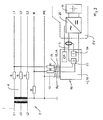
- the Fig. 1 shows a power supply system 2, which is designed as a grounded 3-phase supply network with the active conductors L1, L2, L3 and N and the protective conductor PE.
- the power supply system 2 consists of the main system 4 and a branching from the main system 4 3-phase supply line 8 and another branched off from the main system 4 single-phase supply line 10.
- To the supply lines 8, 10 each load as a load L via load terminals 14 is connected the supply lines 8, 10, a device 15 according to the invention is connected in each case between the load terminals 14 and the load L.
- the conduction and contact resistances of the power supply system 2 are shown as concentrated loss resistors R.
- the device 15 for setting a load current I l has a voltage measuring device 22 and a current measuring device 24.
- the voltage measuring device 22 measures the terminal voltage U k occurring at the load terminals 14 between the conductor L 1 and the neutral conductor N
- the current measuring device 24 measures the load current I 1 flowing through the conductors L 1 and N of the supply line 10, which flows through the load L.
- the current / voltage measurement determines the "internal" resistance R i of the power supply system 2 "seen” by the charging connections 14, which essentially results from the loss resistances R and permits a statement about the electrical state of the power supply system 2.
- the device 15 comprises a comparison device 26 for monitoring the internal resistance R i to exceed a predefinable internal resistance limit, a setting 28 for changing and reducing the load current I l , a shutdown device 30 to interrupt the load operation, a computing unit 32 for Linking of the measured and preset values and a control unit 34 for sequencing the measurement and calculation tasks.
- Fig.2 shows an application of the method according to the invention for charging an energy storage device 40 of an electric vehicle EV by means of an on-board charger 20.
- the electric vehicle EV is connected via a plug-in device 12 with load connections (charging connections) 14 and by means of charging cable 16 to the conductors L1, N and PE of the supply line 10 ,
- a mobile protection device 18 (IC-CPD - In-Cable Control and Protective Device) with a pilot function (CP - Control Pilot) for communication with the charger 20 located in the electric vehicle EV.
- IC-CPD In-Cable Control and Protective Device
- CP - Control Pilot pilot function
- the protective device 18 known from the prior art has been expanded by the functionality according to the invention of the internal resistance-dependent adjustment of the load current I l , so that the thus modified protective device 18 comprises the functional scope of the device 15 according to the invention and thus the determination of an effective at the load terminals 14 internal resistance R. i of the power supply system 2 and the adjustment of the load current I l allows. In the illustrated embodiment, only the functions of voltage measurement 22 and current measurement 24 are shown.
- the modified protective device 18 also includes the functional blocks, not shown, comparison device (26), setting device (28), shut-down device (30), arithmetic unit (32) and control unit (34).
- the device 15 according to the invention can also be used as in FIG Fig. 1 shown integrated as a separate functional unit in the charging cable 16 or be upstream of this as a separate structural unit or distributed to several structural units including the protection device 18.
- the voltage measuring device 22 measures the voltage measuring device 22 at the load terminals 14 - here in the function as charging terminals - the occurring terminal voltage U k , which is also connected as a supply voltage to the charger 20 of the electric vehicle EV.
- the current measuring device 24 measures the load current I l flowing via the supply line 10, which is supplied as a charging current to the charger 20 of the electric vehicle EV.
- This current / voltage measurement can be effective by means of the determination and monitoring of the invention at the load terminals 14 Internal resistance R i of the power supply system 2 to a statement about the electrical state of the power supply system 2 and allows adaptation of the charging current (load current I l ) to the quality of the supply network.
- a control signal for adjusting the load current I l can be forwarded by means of the pilot function CP to the charger 20 located in the electric vehicle EV.
- a warning message can be made directly to the protection device 18 by a visual and / or audible indication or can be forwarded by CP signal to the in-vehicle charger 20 and reach the display in the electric vehicle EV.
Landscapes
- Engineering & Computer Science (AREA)
- Power Engineering (AREA)
- Transportation (AREA)
- Mechanical Engineering (AREA)
- Physics & Mathematics (AREA)
- General Physics & Mathematics (AREA)
- Charge And Discharge Circuits For Batteries Or The Like (AREA)
- Remote Monitoring And Control Of Power-Distribution Networks (AREA)
Abstract
Die Erfindung betrifft ein Verfahren und eine Vorrichtung zur Einstellung eines Laststroms während des Betriebs einer Last, die über Lastanschlüsse mit einer Versorgungsleitung eines Stromversorgungssystems verbunden ist. Dabei wird ein an den Lastanschlüssen wirksamer Innenwiderstand des Stromversorgungssystems bestimmt und zur Einstellung des Laststroms herangezogen. Der Grundgedanke der vorliegenden Erfindung beruht auf der Bestimmung und Überwachung des Innenwiderstandes des versorgenden Stromnetzes, um mögliche Gefährdungen frühzeitig zu erkennen und geeignete Handlungsmaßnahmen einzuleiten. Anhand des bestimmten Innenwiderstandswertes kann eine Aussage über die Qualität des Stromversorgungssystems, wie beispielsweise einer Gebäudeinstallation, von dem Hauptstromverteiler über die Versorgungsleitung in dem speisenden Leitungsabgang bis zu den Lastanschlüssen getroffen werden.The invention relates to a method and a device for adjusting a load current during the operation of a load which is connected via load connections to a supply line of a power supply system. In this case, an effective at the load terminals internal resistance of the power supply system is determined and used to adjust the load current. The basic idea of the present invention is based on the determination and monitoring of the internal resistance of the supplying power network in order to recognize potential hazards at an early stage and to initiate suitable action measures. Based on the determined internal resistance value, it is possible to make a statement about the quality of the power supply system, such as a building installation, from the main power distributor via the supply line in the feeding cable outlet to the load terminals.
Description
Die Erfindung betrifft ein Verfahren und eine Vorrichtung zur Einstellung eines Laststroms während des Betriebs einer Last, die über Lastanschlüsse mit einer Versorgungsleitung eines Stromversorgungssystems verbunden ist.The invention relates to a method and a device for adjusting a load current during the operation of a load which is connected via load connections to a supply line of a power supply system.
Ausgehend von einer Schaltungsanordnung, bei der ein elektrischer Verbraucher als Last an eine Versorgungsleitung eines Stromversorgungssystems angeschlossen ist, muss im Hinblick auf die elektrische Sicherheit gewährleistet sein, dass der Laststrom über die Lastanschlüsse zu dem Verbraucher und damit auch der Strom in der Versorgungsleitung einen maximalen Wert nicht überschreitet. Gerade in älteren oder unzureichend abgesicherten Verteilanlagen des Stromversorgungssystems oder an Lastanschlüssen mit hohen Kontakt- oder Übergangswiderständen kann bei dem Betrieb mit hohen Lastströmen die Brandgefahr steigen, falls die Verlustleistung infolge eines erhöhten elektrischen Widerstands nicht abgeführt werden kann. Oftmals ist zwar hinsichtlich der Stromstärke eine maximale Belastbarkeit der Versorgungsleitung nominal bekannt, jedoch bleibt der aktuelle technische Zustand der Installation dabei außer Acht, so dass die Gefahr einer Überlastung besteht.Starting from a circuit arrangement in which an electrical load is connected as a load to a supply line of a power supply system, it must be ensured in terms of electrical safety that the load current through the load connections to the load and thus the current in the supply line has a maximum value does not exceed. Especially in older or insufficiently secured distribution systems of the power supply system or load connections with high contact or contact resistance, the risk of fire when operating with high load currents, if the power loss can not be dissipated due to increased electrical resistance. Often, although the power rating of a maximum load capacity of the supply line nominally known, but the current technical condition of the installation remains disregarded, so there is a risk of overloading.
Zur weiteren Erläuterung der Aufgabenstellung sei im Folgenden als Beispiel für einen Lastbetrieb ein Ladevorgang eines Elektrofahrzeugs betrachtet. Dabei entspricht das Bordnetz des Elektrofahrzeuges mit dem aufzuladenden elektrischen Energiespeicher der Last und der in das Elektrofahrzeug fließende Ladestrom bildet den Laststrom.For further explanation of the task is considered below as an example of a load operation, a charging of an electric vehicle. In this case, the electrical system of the electric vehicle with the electrical energy storage to be charged corresponds to the load and the charging current flowing into the electric vehicle forms the load current.
Da die elektrischen Energiespeicher eines Elektrofahrzeugs regelmäßig aufgeladen werden, sind auch hier die Risiken zu beachten, die während des Ladevorgangs bestehen. Insbesondere wenn das Elektrofahrzeug zur Aufladung an eine handelsübliche Steckdose angeschlossen wird, muss sichergestellt sein, dass das dahinterliegende Stromversorgungsnetz auch für hohe Lastströme (Ladeströme) ausgelegt ist. So kann der Ladestrom, der über die Ladeanschlüsse einer Schuko- oder CEE-Steckdose fließt, bei ungesteuertem Laden (Lademodus 2) bis zu 32 A betragen.Since the electric energy storage of an electric vehicle is charged regularly, the risks that exist during the charging process here are also to be considered. In particular, when the electric vehicle is connected for charging to a standard electrical outlet, it must be ensured that the underlying power supply network is designed for high load currents (charging currents). Thus, the charging current flowing through the charging ports of a Schuko or CEE socket, with uncontrolled charging (Charge mode 2) can be up to 32 A.
Einige Ladegeräte bieten dabei eine Einstellmöglichkeit des Ladestroms. Der Benutzer kann einen reduzierten maximalen Ladestrom wählen, um diesen den Gegebenheiten der örtlichen Elektroinstallation anzupassen.Some chargers offer an adjustment of the charging current. The user can choose a reduced maximum charging current in order to adapt it to the conditions of the local electrical installation.
Insbesondere ist im Zuge der fortschreitenden Entwicklung zur Elektromobilität derzeit nicht sichergestellt, dass ein Elektrofahrzeug zur Aufladung stets an eine vorschriftsmäßig ausgeführte Elektroinstallation angeschlossen ist. Das sichere und zuverlässige Laden von Elektrofahrzeugen ist somit ebenso wie das Betreiben einer konventionellen Last unmittelbar mit dem elektrischen Zustand der Gebäudeinstallation verbunden. Dies gilt umso mehr, wenn bei dem Anschluss des Verbrauchers an handelsüblichen Steckdosen auch ungeeignete Verlängerungskabel verwendet werden.In particular, as electromobility progresses, there is currently no assurance that an electric vehicle will always be connected to a properly designed electrical installation for charging. The safe and reliable charging of electric vehicles is therefore just as the operation of a conventional load directly connected to the electrical state of the building installation. This is even more true if unsuitable extension cords are used when connecting the consumer to standard sockets.
Als Nachteil erweist sich bei den vorgenannten Anordnungen, dass während des Lastbetriebs der aktuelle elektrische Zustand des versorgenden Netzes, insbesondere hinsichtlich der Qualität seiner Versorgungsleitungen, nicht berücksichtigt wird.A disadvantage in the aforementioned arrangements proves that during load operation, the current electrical state of the supplying network, in particular with regard to the quality of its supply lines, is not considered.
Der vorliegenden Erfindung liegt somit die Aufgabe zu Grunde, ein Verfahren und eine Vorrichtung vorzuschlagen, welche die elektrische Sicherheit während des Betriebs einer Last an einer Versorgungsleitung eines Stromversorgungssystems erhöht.The present invention is therefore based on the object to propose a method and a device which increases the electrical safety during the operation of a load on a supply line of a power supply system.
Bezogen auf ein Verfahren wird diese Aufgabe in Verbindung mit dem Oberbegriff des Anspruchs 1 dadurch gelöst, dass ein an den Lastanschlüssen wirksamer Innenwiderstand des Stromversorgungssystems bestimmt und zur Einstellung des Laststroms herangezogen wird.Relative to a method, this object is achieved in conjunction with the preamble of claim 1, characterized in that an effective at the load terminals internal resistance of the power supply system is determined and used to adjust the load current.
Der Grundgedanke der vorliegenden Erfindung beruht in vorteilhafterweise auf der Bestimmung und Überwachung des Innenwiderstandes des versorgenden Stromnetzes, um mögliche Gefährdungen frühzeitig zu erkennen und geeignete Handlungsmaßnahmen einzuleiten.The basic idea of the present invention is advantageously based on the determination and monitoring of the internal resistance of the supplying power network in order to detect potential hazards at an early stage and to initiate suitable measures of action.
Als Innenwiderstand - im Folgenden mit Ri benannt - wird hier der von außerhalb des Stromversorgungssystems an den Lastanschlüssen wirksame elektrische Widerstand des Stromversorgungssystems bezeichnet.As an internal resistance - hereinafter referred to as R i - is here called the effective from outside the power supply system to the load terminals electrical resistance of the power supply system.
Anhand des bestimmten Innenwiderstandswertes Ri kann eine Aussage über die Qualität des Stromversorgungssystems, wie beispielsweise einer Gebäudeinstallation, von dem Hauptstromverteiler über die Versorgungsleitung in dem speisenden Leitungsabgang bis zu den Lastanschlüssen getroffen werden.On the basis of the determined internal resistance value R i , a statement can be made about the quality of the power supply system, such as a building installation, from the main power distributor via the supply line in the feeding cable outlet to the load terminals.
In bevorzugter Ausgestaltung erfolgt während des Lastbetriebs eine ständige Überwachung des Innenwiderstands Ri auf eine Überschreitung eines vorgebbaren Innenwiderstands-Grenzwertes.In a preferred embodiment, a continuous monitoring of the internal resistance R i is carried out during load operation to an exceeding of a predefinable internal resistance limit value.
Während des Lastbetriebs wird der Innenwiderstand Ri kontinuierlich daraufhin überprüft, ob ein für das Stromversorgungssystem geltender spezifischer Innenwiderstands-Grenzwert überschritten wird. Ist eine derartige Verschlechterung feststellbar, so kann darauf automatisiert oder durch menschlichen Eingriff reagiert werden. Damit ist eine frühzeitige Erkennung kritischer Versorgungsstromkreise möglich, womit mögliche Brandschäden verhindert werden können.During load operation, the internal resistance R i is continuously checked as to whether a specific internal resistance limit applicable to the power supply system is exceeded. If such a deterioration can be detected, it can be automated or responded by human intervention. This makes it possible to detect critical supply circuits at an early stage, which can prevent possible fire damage.
Weiterhin werden zur Bestimmung des Innenwiderstands Ri mindestens eine an den Lastanschlüssen zwischen einem Außenleiter und einem Neutralleiter anliegende Klemmenspannung Uk und der dazugehörige über die Lastanschlüsse fließender Laststrom I1 gemessen.Furthermore, to determine the internal resistance R i, at least one terminal voltage U k applied to the load terminals between an outer conductor and a neutral conductor and the associated load current I 1 flowing through the load terminals are measured.
Der bezüglich der Lastanschlüsse zwischen einem Außenleiter und dem Neutralleiter wirksame Innenwiderstand Ri des Stromversorgungssystems wird durch eine Strom-/Spannungsmessung an einem bestimmten Klemmenpaar, beispielsweise L1 und N, ermittelt. Dazu wird die an den Lastanschlüssen anliegende Klemmenspannung Uk abgegriffen und der über diese Kontakte fließende Laststrom Il gemessen. Neben der Heranziehung zur Bestimmung des Innenwiderstands Ri kann aus dem Verlauf der gemessenen Klemmenspannung Uk auch eine Leistungsüberlastung infolge eines zu hohen Laststroms Il, beispielsweise durch einen schadhaften Verbraucher, erkannt werden. Im Falle eines mehrphasigen Stromversorgungsnetzes erfolgt die Bestimmung mindestens eines Innenwiderstands Ri, beispielsweise zwischen dem Außenleiter L1 und dem Neutralleiter N, es können aber auch alternativ oder zusätzlich die Innenwiderstände Ri bezüglich der jeweiligen weiteren Außenleiter, beispielweise L2 und L3, und dem Neutralleiter N bestimmt, überwacht und zur Beurteilung der Qualität des Stromversorgungsnetzes herangezogen werden.The with respect to the load connections between an outer conductor and the neutral conductor effective internal resistance R i of the power supply system is determined by a current / voltage measurement at a certain terminal pair, for example, L1 and N. For this purpose, the voltage applied to the load terminals terminal voltage U k is tapped and the current flowing through these contacts load current I l measured. In addition to being used to determine the internal resistance R i, it is also possible to detect from the course of the measured terminal voltage U k a power overload as a result of an excessively high load current I l , for example due to a faulty load. In the case of a multi-phase power supply network, the determination of at least one internal resistance R i , for example, between the outer conductor L1 and the neutral conductor N, but it can also alternatively or additionally the internal resistance R i with respect to the respective other outer conductor, for example, L2 and L3, and the neutral conductor N. determined, monitored and used to assess the quality of the power grid.
In weiterer vorteilhafter Ausgestaltung erfolgt die Bestimmung des Innenwiderstands Ri durch eine Laststromänderung (ΔIl) bei gleichzeitiger Bestimmung einer Spannungsdifferenz (ΔU), welche sich aus der gemessenen Klemmenspannung (Uk) ergibt.In a further advantageous embodiment, the determination of the internal resistance R i by a load current change (.DELTA.I l ) with simultaneous determination of a voltage difference (.DELTA.U), which results from the measured terminal voltage (U k ).
Für die Bestimmung des Innenwiderstandes Ri wird der Laststrom Il um einen Betrag ΔIl geändert und die sich daraus ergebende Spannungsdifferenz ΔU an den Lastanschlüssen durch Messung der Klemmenspannung Uk zur Berechnung des Innenwiderstands Ri herangezogen. Erfolgt beispielsweise die Strom-/Spannungsmessung ausgehend von einer als konstant angenommenen Leerlaufspannung U0, so gilt unter der weiteren Annahme der Gültigkeit einer linearen Strom/Spannungs-Beziehung (ohmsches Gesetz) dann für den Innenwiderstand Ri = ΔU/ΔIl mit ΔU = U0-Uk. Die Spannungsdifferenz ΔU kann aber auch in einem beliebigen Lastfall ohne Kenntnis der Leerlaufspannung U0 bestimmt werden.For the determination of the internal resistance R i , the load current I l is changed by an amount ΔI l and the resulting voltage difference ΔU at the load terminals by measuring the terminal voltage U k used to calculate the internal resistance R i . If, for example, the current / voltage measurement is based on an open-circuit voltage U 0 assumed to be constant, the validity of a linear current / voltage relationship (ohmic law) is then valid for the internal resistance R i = ΔU / ΔI l with ΔU = U 0 -U k . The voltage difference .DELTA.U can also be determined in any load case without knowing the open circuit voltage U 0 .
Mit Vorteil erfolgt die Laststromänderung ΔIl zur Bestimmung des Innenwiderstands Ri durch eine impulsförmige Änderung des Laststroms ΔIl um einen vorgebbaren Betrag.Advantageously, the load current change .DELTA.I l for determining the internal resistance R i by a pulse-shaped change of the load current .DELTA.I l by a predetermined amount.
Mit dieser impulsförmigen Laststromänderung ΔIl, die einer kurzzeitigen Laststromänderung ΔIl in Form eines Messimpulses entspricht, wird bei gleichzeitiger Bestimmung der sich aus dieser Stromänderung ΔIl ergebenden Spannungsdifferenz ΔU eine Bestimmung des Innenwiderstands Ri durchgeführt. Dabei kann bei einer Erhöhung des Laststroms dieser höchstens bis zu einem maximalen Laststrom Ilmax ansteigen. Unter einer impulsförmigen Laststromänderung ΔIl ist eine in Bezug auf typischerweise vorkommende Netzspannungsschwankungen, die langsamerer Natur sind und automatisch ausgeregelt werden, eine schnelle Änderung kurzer Dauer zu verstehen. Die Laststromänderung ΔIl und die korrespondierende Bestimmung der Spannungsdifferenz ΔU zur Bestimmung des Innenwiderstands Ri werden damit nicht von den typischen, bei dem Betrieb eines Stromversorgungssystems auftretenden, Netzspannungsschwankungen beeinflusst.With this pulse-shaped load current change ΔI l , which corresponds to a short-term load current change ΔI l in the form of a measuring pulse, a determination of the internal resistance R i is carried out while simultaneously determining the voltage difference ΔU resulting from this current change ΔI l . In this case, with an increase in the load current, this can increase at most up to a maximum load current I lmax . A pulsed load current change ΔI l is understood to mean a rapid change of short duration with respect to typically occurring mains voltage fluctuations, which are of a slower nature and are automatically corrected. The load current change .DELTA.I l and the corresponding determination of the voltage difference .DELTA.U for determining the internal resistance R i are thus not affected by the typical, occurring in the operation of a power supply system, mains voltage fluctuations.
Weiterhin wird die Bestimmung des Innenwiderstands Ri manuell oder zeitgesteuert ausgelöst. Eine manuelle Auslösung der Bestimmung des Innenwiderstands Ri kann von dem Anlagenbetreiber beispielsweise zu Beginn eines neu aufzunehmenden Lastbetriebs, insbesondere nach der Neuinstallation eines Verbrauches vor dessen erstmalige Inbetriebnahme, durchgeführt werden. Daneben bietet sich eine zeitgesteuerte Ausführung der Bestimmung des Innenwiderstands Ri während des Lastbetriebs an, um über einen längeren Zeitraum hinweg schleichende Veränderungen in der Qualität des Stromversorgungssystems feststellen zu können. Hierzu bietet sich eine wiederholte Bestimmung in einstellbaren Zeitintervallen an.Furthermore, the determination of the internal resistance R i is triggered manually or timed. A manual triggering of the determination of the internal resistance R i can be made by the plant operator, for example, at the beginning of a new load operation, especially after the new installation of a consumption before its initial startup, be performed. In addition, there is a timed execution of the determination of the internal resistance R i during load operation in order to be able to determine creeping changes in the quality of the power supply system over a relatively long period of time. For this purpose, a repeated determination in adjustable time intervals offers itself.
Vorteilhafterweise wird die Bestimmung des Innenwiderstands Ri während des Lastbetriebs durch eine betriebsbedingte Änderung des Laststroms Il ausgelöst. Ergänzend zu einer manuellen oder zeitgesteuerten Bestimmung des Innenwiderstands Ri kann diese auch in Abhängigkeit des zeitlichen Verlaufs des Laststroms Il ausgelöst werden. Ändert sich der Laststrom unter verschiedenen Betriebs- oder Nutzungsbedingungen des Verbrauchers, wie z.B. die Stromaufnahme eines Elektroschweißgerätes, so kann diese Stromänderung dazu genutzt werden, eine Strom-/Spannungsmessung zur Bestimmung des Innenwiderstands Ri auszulösen.Advantageously, the determination of the internal resistance R i is triggered during load operation by an operational change of the load current I l . In addition to a manual or timed determination of the internal resistance R i , this can also be triggered as a function of the time profile of the load current I l . If the load current changes under different operating or service conditions of the consumer, such as the current consumption of an electric welding device, this current change can be used to trigger a current / voltage measurement to determine the internal resistance R i .
Bevorzugt ist ein maximaler Laststrom Ilmax voreinstellbar. Damit ist die Möglichkeit gegeben, die Qualität des versorgenden Stromnetzes im Vorfeld durch die Einstellung eines anlagenspezifischen maximalen Laststroms Ilmax zu berücksichtigen. Entweder kann so der Laststrom Il aus Sicherheitsgründen auf einen maximalen Laststrom Ilmax begrenzt werden oder bei Gewissheit einer zuverlässig funktionierenden Installation kann die Last mit der für dieses Stromversorgungssystem maximal zulässigen Stromstärke betrieben werden.Preferably, a maximum load current I lmax can be preset . This makes it possible to consider the quality of the supplying power network in advance by setting a plant-specific maximum load current I lmax . For safety reasons, either the load current I l can be limited to a maximum load current I lmax , or if a reliably functioning installation is certain, the load can be operated with the maximum permissible current intensity for this power supply system.
Zur Einstellung des anlagenspezifischen maximalen Laststroms Ilmax kann dieser aus einer maximal zulässigen Verlustleistung Pvmax in dem Stromversorgungssystem abgeleitet werden. Hierbei wählt der Benutzer nicht direkt einen maximalen Stromwert, sondern orientiert sich an der durch den Innenwiderstand Ri des Stromversorgungssystems hervorgerufenen Verlustleistung, aus der ein verlustabhängiger maximaler Laststrom Ilmax berechnet werden kann. Beispielsweise besteht ab einer Verlustleistung von 60W im Lastkreis des Stromversorgungssystems bereits Brandgefahr. Der maximale Ladestrom Ilmax kann daher aus einer maximal zulässigen Verlustleistung Pvmax, von beispielsweise 30W gemäß Ilmax = Pvmax/ΔU abgeleitet werden, wobei ΔU die über dem Innenwiderstand Ri des Stromversorgungssystems abfallende Spannung ist.To set the plant-specific maximum load current I lmax this can be derived from a maximum allowable power loss P vmax in the power supply system. In this case, the user does not directly select a maximum current value, but is based on the power loss caused by the internal resistance R i of the power supply system, from which a loss- dependent maximum load current I lmax can be calculated. For example, there is one Power loss of 60W in the load circuit of the power supply system already fire. The maximum charging current I lmax can therefore be derived from a maximum permissible power loss P vmax , for example 30W according to I lmax = P vmax / ΔU, where ΔU is the voltage drop across the internal resistance R i of the power supply system.
Zweckmäßigerweise erfolgt bei einer Überschreitung des Innenwiderstands-Grenzwertes eine Abschaltung des Lastbetriebs.Appropriately, when the internal resistance limit value is exceeded, the load operation is switched off.
Um eine Gefährdung für Personen und Anlagen durch eine mögliche Brandentwicklung auszuschließen, wird der Lastbetrieb mittels einer Abschalteinrichtung unterbrochen, wenn der Innenwiderstand Ri einen, gegebenenfalls anlagenspezifischen, Innenwiderstands-Grenzwert überschreitet. Im Falle der Aufladung eines elektrischen Energiespeichers eines Elektrofahrzeuges würde damit der Ladevorgang zumindest temporär beendet werden.In order to exclude a risk to persons and equipment by a possible fire development, the load operation is interrupted by means of a shutdown device when the internal resistance R i exceeds a, possibly plant-specific, internal resistance limit. In the case of charging an electrical energy storage of an electric vehicle so that the charging process would be terminated at least temporarily.
Alternativ zu der Abschaltung des Lastbetriebs kann bei einer Überschreitung des Innenwiderstands-Grenzwertes eine Reduktion des Laststroms Il erfolgen.As an alternative to switching off the load operation, if the internal resistance limit value is exceeded, the load current I l can be reduced.
Sofern der Verbraucher dafür ausgelegt ist, kann dieser bei geringerer Stromaufnahme und gegebenenfalls mit eingeschränkter Funktionalität weiter betrieben werden. Insbesondere kann im Falle der Aufladung eines Elektrofahrzeugs dadurch sichergestellt werden, dass bei einer während des Ladebetriebs auftretenden Verschlechterung der Qualität des Stromversorgungssystems eine Gefährdung durch Überlastung des Stromversorgungssystems nahezu ausgeschlossen ist, die Aufladung der Energiespeicher aber nicht unterbrochen wird.If the consumer is designed for this, it can be operated at a lower power consumption and possibly with limited functionality. In particular, in the case of charging of an electric vehicle can be ensured that at a occurring during the charging deterioration of the quality of the power supply system, a risk of overloading the power supply system is almost impossible, but the charging of the energy storage is not interrupted.
In weiterer Ausgestaltung erfolgt in Kombination mit einer elektrischen Schutzeinrichtung in dem Stromversorgungssystem bei einer Überschreitung des Innenwiderstands-Grenzwertes eine Abschaltung eines die Last versorgenden Laststromkreises in dem Stromversorgungssystem.In a further embodiment, in combination with an electrical protective device in the power supply system, when the internal resistance limit value is exceeded, the load is switched off supplying load circuit in the power supply system.
In Verbindung mit einer in dem Stromversorgungssystem angeordneten Schutzeinrichtung kann somit bei Erkennung einer Überschreitung des Innenwiderstands-Grenzwertes eine Abschaltung zumindest des den Laststrom Il führenden Teils des Stromversorgungsnetzes erfolgen. Die elektrische Sicherheit wird dadurch weiter gesteigert.In connection with a protective device arranged in the power supply system, a disconnection of at least the part of the power supply network carrying the load current I 1 can thus take place upon detection of an exceeding of the internal resistance limit value. The electrical safety is thereby further increased.
Vorzugsweise wird im Falle einer Auslösung einer Überstromschutzeinrichtung in einem die Last versorgenden Laststromkreis des Stromversorgungssystems der zugehörige Laststrom Il aufgezeichnet und als ein Laststrom-Grenzwert verwendet.Preferably, in the event of tripping of an overcurrent protection device in a load circuit of the power system feeding the load, the associated load current I l is recorded and used as a load current limit.
Sollte die Überstromschutzeinrichtung in dem Stromversorgungssystem infolge eines zu hohen über die Lastanschlüsse fließenden Laststroms Il auslösen, so kann der im Moment der Auslösung vorherrschende Laststrom Il aufgezeichnet und in einem darauffolgenden Lastbetrieb als Laststrom-Grenzwert verwendet werden. Aus diesem Laststrom-Grenzwert kann dann alternativ mit einem Sicherheitsabschlag der maximale Laststrom Ilmax abgeleitet werden. Damit wird eine erneute Auslösung der Überstromschutzeinrichtung in dem Stromversorgungssystem infolge eines zu hohen Laststroms Il bei einer Wiederaufnahme des Lastbetriebs vermieden.If the overcurrent protection device in the power supply system due to excessive current flowing through the load terminals load current I l trigger, the prevailing at the moment of triggering load current I L can be recorded and used in a subsequent load operation as load power limit. From this load current limit value, the maximum load current I lmax can then be derived alternatively with a safety discount . Thus, a renewed tripping of the overcurrent protection device in the power supply system due to an excessive load current I l is avoided when resuming the load operation.
In weiterer Ausgestaltung wird mindestens ein Schwellwert für den Innenwiderstand Ri berechnet, bei dessen Überschreitung eine Warnmeldung ausgelöst wird.In a further refinement, at least one threshold value is calculated for the internal resistance R i , above which a warning message is triggered.
Durch die Warnmeldung wird der Benutzer auf einen sich verschlechternden oder bevorstehenden kritischen Zustand des versorgenden Stromnetzes hingewiesen und kann dazu veranlasst werden, die Anlage überprüfen zu lassen, bevor ein Störfall eintritt.The alert alerts the user to a deteriorating or imminent critical condition of the utility grid and may cause the system to be checked before an incident occurs.
In bevorzugter Ausführung wird mittels eines Ladestroms als Laststrom Il ein Ladevorgang eines elektrischen Energiespeichers durchgeführt. Das erfindungsgemäße Verfahren eignet sich besonders für die Überwachung eines Ladevorgangs eines elektrischen Energiespeichers, da die Ladestromstärke in der Regel nicht an einen bestimmten, konstanten Stromwert gebunden ist. Der Ladevorgang kann somit als Lastbetrieb aufgefasst werden, wobei der Ladestrom dem Laststrom Il entspricht. Durch die Einstellung des Laststroms Il unter Zuhilfenahme des errechneten Innenwiderstands Ri kann der Energiespeicher mit einem für das versorgende Netz angepassten, möglichst maximalen, Laststrom Il geladen werden.In a preferred embodiment, a charging process of an electrical energy store is carried out by means of a charging current as a load current I l . The inventive method is particularly suitable for monitoring a charging of an electrical energy storage, since the charging current is usually not tied to a specific, constant current value. The charging process can thus be understood as a load operation, the charging current corresponding to the load current I l . By adjusting the load current I l with the aid of the calculated internal resistance R i , the energy store can be charged with a maximum load current I 1 adapted to the supplying network.
Mit Vorteil wird bei dem Ladevorgang der elektrische Energiespeicher eines mit einem Ladegerät versehenen Elektrofahrzeugs aufgeladen, wobei das Elektrofahrzeug mit einem Ladekabel über die Lastanschlüsse mit der Versorgungsleitung des Stromversorgungssystems verbunden ist.Advantageously, during the charging process, the electrical energy store of an electric vehicle provided with a charger is charged, wherein the electric vehicle is connected to a charging cable via the load connections to the supply line of the power supply system.
Neben der Aufladung stationärer Energiespeicher kann das erfindungsgemäße Verfahren bei der Aufladung der elektrischen Energiespeicher von Elektrofahrzeugen angewendet werden. Dabei ist das Elektrofahrzeug mit dem Ladekabel über eine Steckvorrichtung, welche die Lastanschlüsse umfasst, mit der Versorgungsleitung des Stromversorgungssystems verbunden.In addition to the charging of stationary energy storage method of the invention can be applied to the charging of electric energy storage of electric vehicles. In this case, the electric vehicle with the charging cable via a plug-in device, which includes the load terminals, connected to the supply line of the power supply system.
Bezogen auf eine Vorrichtung wird die der Erfindung zu Grunde liegende Aufgabe in Verbindung mit dem Oberbegriff des Anspruchs 17 gelöst durch eine Strom- und eine Spannungsmesseinrichtung zur Bestimmung eines an den Lastanschlüssen wirksamen Innenwiderstands Ri des Stromversorgungssystems.Relative to a device, the object underlying the invention in conjunction with the preamble of claim 17 is achieved by a current and a voltage measuring device for determining an effective at the load terminals internal resistance R i of the power supply system.
In Umsetzung des erfindungsgemäßen Verfahrens weist die erfindungsgemäße Vorrichtung eine Strom- und eine Spannungsmesseinrichtung auf. Aus den an den Lastanschlüssen erfassten Strom- und Spannungswerten kann der an diesen "Klemmen" wirksame Innenwiderstand Ri des Stromversorgungssystems bestimmt werden. Die Strommesseinrichtung kann dabei als Differenzstrommesseinrichtung ausgeführt sein.In implementation of the method according to the invention, the device according to the invention comprises a current and a voltage measuring device. From the current and voltage values detected at the load terminals, the internal resistance R i of the power supply system effective at these "terminals" can be determined. The current measuring device can be designed as a differential current measuring device.
In weiterer vorteilhafter Ausgestaltung umfasst die Vorrichtung eine Vergleichseinrichtung zur Überwachung des Innenwiderstands Ri auf eine Überschreitung eines vorgebbaren Innenwiderstands-Grenzwertes.In a further advantageous embodiment, the device comprises a comparison device for monitoring the internal resistance R i to an exceeding of a predefinable internal resistance limit value.
Entsprechend dem Grundgedanken der vorliegenden Erfindung wird der berechnete Innenwiderstand Ri durch Vergleich mit einem Innenwiderstands-Grenzwert auf eine Überschreitung hin überwacht, um eine Aussage über den momentanen Zustand und damit die Qualität der Installation des Stromversorgungssystems zu erhalten.In accordance with the principles of the present invention, the calculated internal resistance R i is monitored for overshoot by comparison with an internal resistance limit in order to obtain an indication of the current state and thus the quality of the installation of the power supply system.
Weiterhin weist die Vorrichtung eine Einstelleinrichtung zur Änderung des Laststroms Il für die Bestimmung des Innenwiderstands Ri und zur Reduktion des Laststroms Il bei einer Überschreitung des Innenwiderstands-Grenzwertes auf.Furthermore, the device has an adjusting device for changing the load current I l for the determination of the internal resistance R i and for reducing the load current I l when the internal resistance limit value is exceeded.
Der Innenwiderstand Ri wird gemäß der Beziehung Ri = ΔU/ΔIl aus der Änderung des Laststroms ΔIl und der sich daraufhin einstellenden Spannungsänderung ΔU berechnet. Um die Stromänderung ΔIl für diese Berechnung sowie bei einer Überschreitung des Innenwiderstands-Grenzwertes gegebenenfalls eine Reduktion des Laststroms Il vornehmen zu können, weist die Vorrichtung diese Einstelleinrichtung auf. Dabei kann auch eine Reduktion des Laststroms Il auf den Wert Null erfolgen, was einer Unterbrechung des Lastbetriebes entspricht.The internal resistance R i is calculated according to the relationship R i = .DELTA.U / .DELTA.I l from the change of the load current .DELTA.I l and then adjusting voltage change .DELTA.U. In order to be able to make the current change ΔI l for this calculation and, if the internal resistance limit value is exceeded, possibly a reduction of the load current I l , the device has this setting device. It can also be a reduction of the load current I l to zero, which corresponds to an interruption of the load operation.
Zur Abschaltung des Lastbetriebs weist die Vorrichtung weiterhin eine Abschalteinrichtung auf. Bei einer Überschreitung des Innenwiderstands-Grenzwertes kann alternativ oder in Ergänzung nach einer anfänglichen Reduktion des Laststroms Il eine Abschaltung des Lastbetriebs mittels der Abschaltvorrichtung erfolgen.To shut off the load operation, the device further comprises a shutdown device. When the internal resistance limit value is exceeded, as an alternative or in addition, after an initial reduction of the load current I l, the load operation can be switched off by means of the switch-off device.
In weiterer vorteilhafter Ausgestaltung weist die Vorrichtung eine Recheneinheit zur Verknüpfung der gemessenen und voreingestellten Werte sowie eine Steuereinheit zur Ablaufsteuerung der Mess- und Berechnungsaufgaben auf.In a further advantageous embodiment, the device has a computing unit for linking the measured and preset values and a control unit for sequencing the measurement and calculation tasks.
Die Recheneinheit führt auf der Grundlage der gemessenen sowie der voreingestellten und gespeicherten Strom- und Spannungswerte die Berechnungen zur Bestimmung des Innenwiderstands Ri aus. Die Steuereinheit kann als Mikrocontroller ausgeführt sein und legt die zeitliche Abfolge der Verfahrensschritte fest. So bestimmt die Steuereinheit beispielsweise wann und auf Grund welcher Ereignisses eine erneute Bestimmung des Innenwiderstands Ri durchgeführt werden soll.The arithmetic unit carries out the calculations for determining the internal resistance R i on the basis of the measured and the preset and stored current and voltage values. The control unit can be designed as a microcontroller and determines the time sequence of the method steps. For example, the control unit determines when and on the basis of which event a renewed determination of the internal resistance Ri is to be carried out.
Weitere vorteilhafte Ausgestaltungsmerkmale ergeben sich aus der nachfolgenden Beschreibung und den Zeichnungen, die bevorzugte Ausführungsformen der Erfindung an Hand von Beispielen erläutern. Es zeigen:
- Fig. 1:
- eine schematische Darstellung eines Stromversorgungsnetzes mit einer erfindungsgemäßen Vorrichtung zur Einstellung eines Laststroms,
- Fig. 2:
- eine Anwendung des Verfahrens zur Aufladung eines Energiespeichers eines Elektrofahrzeugs.
- Fig. 1:
- a schematic representation of a power supply network with a device according to the invention for adjusting a load current,
- Fig. 2:
- an application of the method for charging an energy storage of an electric vehicle.
Die
Für die einphasige Versorgungsleitung 10 seien die Funktionsweise des erfindungsgemäßen Verfahrens und die dieses Verfahren umsetzende erfindungsgemäße Vorrichtung 15 näher erläutert. Die Vorrichtung 15 zur Einstellung eines Laststroms Il weist eine Spannungsmesseinrichtung 22 und eine Strommesseinrichtung 24 auf. Die Spannungsmesseinrichtung 22 misst die an den Lastanschlüssen 14 zwischen dem Leiter L1 und dem Neutralleiter N auftretende Klemmenspannung Uk, und die Strommesseinrichtung 24 den über die Leiter L1 und N der Versorgungsleitung 10 fließenden Laststrom Il, der durch die Last L fließt. Durch die Strom-/Spannungsmessung wird der von den Ladeanschlüssen 14 aus "gesehene" Innenwiderstand Ri des Stromversorgungssystems 2 bestimmt, der sich im Wesentlichen aus den Verlustwiderständen R ergibt und eine Aussage über den elektrischen Zustand des Stromversorgungssystems 2 erlaubt.For the single-
Als weitere Funktionsblöcke umfasst die erfindungsgemäße Vorrichtung 15 eine Vergleichseinrichtung 26 zur Überwachung des Innenwiderstands Ri auf eine Überschreitung eines vorgebbaren Innenwiderstands-Grenzwertes, eine Einstelleinrichtung 28 zur Änderung und Reduktion des Laststroms Il, eine Abschalteinrichtung 30 zur Unterbrechung des Lastbetriebs, eine Recheneinheit 32 zur Verknüpfung der gemessenen und voreingestellten Werte sowie eine Steuereinheit 34 zur Ablaufsteuerung der Mess- und Berechnungsaufgaben.As a further functional blocks, the
Zur Erfüllung der normativen Sicherheitsanforderungen ist bei der Aufladung des elektrischen Energiespeichers 40 des Elektrofahrzeugs EV an einer handelsüblichen Steckdose (Lademodus 2) in dem Ladekabel 16 eine mobile Schutzeinrichtung 18 (IC-CPD - In-Cable Control and Protective Device) mit einer Pilotfunktion (CP - Control Pilot) zur Kommunikation mit dem in dem Elektrofahrzeug EV befindlichen Ladegerät 20 vorgesehen.To meet the normative safety requirements when charging the electrical
Die aus dem Stand der Technik bekannte Schutzeinrichtung 18 ist um die erfindungsgemäße Funktionalität der innenwiderstandsabhängigen Einstellung des Laststroms Il erweitert worden, so dass die derart modifizierte Schutzeinrichtung 18 den Funktionsumfang der erfindungsgemäßen Vorrichtung 15 umfasst und damit die Bestimmung eines an den Lastanschlüssen 14 wirksamen Innenwiderstands Ri des Stromversorgungssystems 2 sowie die Einstellung des Laststroms Il ermöglicht. In dem dargestellten Ausführungsbeispiel sind lediglich die Funktionen der Spannungsmessung 22 und der Strommessung 24 gezeigt. Daneben umfasst die modifizierte Schutzeinrichtung 18 auch die nicht dargestellten Funktionsblöcke Vergleichseinrichtung (26), Einstelleinrichtung (28), Abschalteinrichtung (30), Recheneinheit (32) und Steuereinheit (34).The protective device 18 known from the prior art has been expanded by the functionality according to the invention of the internal resistance-dependent adjustment of the load current I l , so that the thus modified protective device 18 comprises the functional scope of the
Alternativ zu einer vollständigen Implementierung des erfindungsgemäßen Verfahrens in die Schutzeinrichtung 18 kann die erfindungsgemäße Vorrichtung 15 auch wie in
Wie in dem Ausführungsbeispiel mit einer allgemeinen Last L in
Ein Steuersignal zur Einstellung des Laststroms Il kann mittels der Pilotfunktion CP an das im Elektrofahrzeug EV befindliche Ladegerät 20 weitergeleitet werden.A control signal for adjusting the load current I l can be forwarded by means of the pilot function CP to the
Eine Warnmeldung kann unmittelbar an der Schutzeinrichtung 18 durch eine optische und/oder akustische Anzeige erfolgen oder kann mittels CP-Signal an das fahrzeuginterne Ladegerät 20 weitergeleitet und in dem Elektrofahrzeug EV zur Anzeige gelangen.A warning message can be made directly to the protection device 18 by a visual and / or audible indication or can be forwarded by CP signal to the in-
Claims (22)
dadurch gekennzeichnet,
dass ein an den Lastanschlüssen (14) wirksamer Innenwiderstand (Ri) des Stromversorgungssystems (2) bestimmt und zur Einstellung des Laststroms (Il) herangezogen wird.Method for setting a load current (I l ) during the operation of a load (L) which is connected via load terminals (14) to a supply line (10) of a power supply system (2),
characterized,
in that an internal resistance (R i ) of the power supply system (2) which is effective at the load connections (14) is determined and used to set the load current (I l ).
dadurch gekennzeichnet,
dass während des Lastbetriebs eine ständige Überwachung des Innenwiderstands (Ri) auf eine Überschreitung eines vorgebbaren Innenwiderstands-Grenzwertes erfolgt.Method according to claim 1,
characterized,
that during the load operation a constant monitoring of the internal resistance (R i ) takes place on exceeding of a predefinable internal resistance limit value.
dadurch gekennzeichnet,
dass zur Bestimmung des Innenwiderstands (Ri) mindestens eine an den Lastanschlüssen (14) zwischen einem Außenleiter (L1, L2, L3) und einem Neutralleiter (N) anliegende Klemmenspannung (Uk) und der dazugehörige über die Lastanschlüsse (14) fließende Laststrom (Il) gemessen werden.Method according to claim 1 or 2,
characterized,
in that at least one terminal voltage (U k ) applied to the load terminals (14) between an outer conductor (L1, L2, L3) and a neutral conductor (N) and the associated load current flowing through the load terminals (14) are used to determine the internal resistance (R i ) (I l ) are measured.
dadurch gekennzeichnet,
dass die Bestimmung des Innenwiderstands (Ri) erfolgt durch eine Laststromänderung (ΔIl) bei gleichzeitiger Bestimmung einer Spannungsdifferenz (ΔU), welche sich aus der gemessenen Klemmenspannung (Uk) ergibt.Method according to claim 3,
characterized,
that the determination of the internal resistance (R i ) is effected by a load current change (ΔI l ) with simultaneous determination of a voltage difference (ΔU), which results from the measured terminal voltage (U k ).
dadurch gekennzeichnet,
dass die Laststromänderung (ΔIl) zur Bestimmung des Innenwiderstands (Ri) durch eine impulsförmige Änderung des Laststroms (Il) um einen vorgebbaren Betrag erfolgt.Method according to claim 4,
characterized,
that the load current change (.DELTA.I l) for determining the internal resistance (R i) of the load current by a pulse-like change (I l) is carried out by a predetermined amount.
dadurch gekennzeichnet,
dass die Bestimmung des Innenwiderstands (Ri) manuell oder zeitgesteuert ausgelöst wird.Method according to one of claims 1 to 5,
characterized,
that the determination of the internal resistance (R i ) is triggered manually or timed.
dadurch gekennzeichnet,
dass die Bestimmung des Innenwiderstands (Ri) während des Lastbetriebs durch eine betriebsbedingte Änderung des Laststroms Il ausgelöst wird.Method according to one of claims 1 to 6,
characterized,
that the determination of the internal resistance (R i) during the load operation, the load current I l through an operational change is triggered.
dadurch gekennzeichnet,
dass ein maximaler Laststrom (Ilmax) voreinstellbar ist.Method according to one of claims 1 to 7,
characterized,
that a maximum load current (I lmax ) can be preset .
dadurch gekennzeichnet,
dass der maximale Laststrom (Ilmax) aus einer maximal zulässigen Verlustleistung (Pvmax) in dem Stromversorgungssystem (2) abgeleitet wird.Method according to claim 8,
characterized,
that the maximum load current (I L max) of a maximum allowable power dissipation (P vmax) in the power supply system (2) is derived.
dadurch gekennzeichnet,
dass bei einer Überschreitung des Innenwiderstands-Grenzwertes eine Abschaltung des Lastbetriebs erfolgt.Method according to one of claims 2 to 9,
characterized,
that in an overrun of the internal resistance limit value is a shutdown of the load operation.
dadurch gekennzeichnet,
dass bei einer Überschreitung des Innenwiderstands-Grenzwertes eine Reduktion des Laststroms (Il) erfolgt.Method according to one of claims 2 to 9,
characterized,
that in an overrun of the internal resistance limit value, a reduction of the load current (I l) is carried out.
dadurch gekennzeichnet,
dass in Kombination mit einer elektrischen Schutzeinrichtung in dem Stromversorgungssystem (2) bei einer Überschreitung des Innenwiderstands-Grenzwertes eine Abschaltung eines die Last (L) versorgenden Laststromkreises in dem Stromversorgungssystem (2) erfolgt.Method according to one of claims 2 to 11,
characterized,
that in combination with an electrical protective device in the power supply system (2) when the internal resistance limit value is exceeded, a shutdown of a load circuit supplying the load (L) takes place in the power supply system (2).
dadurch gekennzeichnet,
dass im Falle einer Auslösung einer Überstromschutzeinrichtung in einem die Last (L) versorgenden Laststromkreis des Stromversorgungssystems (2) der zugehörige Laststrom (Il) aufgezeichnet und als ein Laststrom-Grenzwert verwendet wird.Method according to one of claims 1 to 12,
characterized,
that in the event of a triggering of an overcurrent protection device in a load (L) supplying the load circuit of the power system (2) of the associated load current is recorded (I l) and used as a load current limit.
dadurch gekennzeichnet,
dass mindestens ein Schwellwert für den Innenwiderstand (Ri) berechnet wird, bei dessen Überschreitung eine Warnmeldung ausgelöst wird.Method according to one of claims 1 to 13,
characterized,
that at least one threshold value for the internal resistance (R i ) is calculated, beyond which a warning message is triggered.
dadurch gekennzeichnet,
dass mittels eines Ladestroms als Laststrom (Il) ein Ladevorgang eines elektrischen Energiespeichers (40) durchgeführt wird.Method according to one of claims 1 to 14,
characterized,
that is carried out by means of a charge current as the load current (I l) a charging an electrical energy accumulator (40).
dadurch gekennzeichnet,
dass bei dem Ladevorgang der elektrische Energiespeicher (40) eines mit einem Ladegerät (20) versehenen Elektrofahrzeugs (EV) aufgeladen wird, wobei das Elektrofahrzeug mit einem Ladekabel (16) über die Lastanschlüsse (14) mit der Versorgungsleitung (10) des Stromversorgungssystems (2) verbunden ist.Method according to claim 15,
characterized,
in that the electric vehicle (EV) is charged with a charging cable (16) via the load connections (14) to the supply line (10) of the power supply system (2 ) connected is.
gekennzeichnet durch
eine Strom- (24) und eine Spannungsmesseinrichtung (22) zur Bestimmung eines an den Lastanschlüssen (14) wirksamen Innenwiderstands (Ri) des Stromversorgungssystems (2).Device for adjusting a load current (I l ) during the operation of a load (L) which is connected via load connections (14) to a supply line (10) of a power supply system (2),
marked by
a current (24) and a voltage measuring device (22) for determining an effective at the load terminals (14) internal resistance (R i ) of the power supply system (2).
gekennzeichnet durch
eine Vergleichseinrichtung (26) zur Überwachung des Innenwiderstands (Ri) auf eine Überschreitung eines vorgebbaren Innenwiderstands-Grenzwertes.Device according to claim 17,
marked by
a comparison device (26) for monitoring the internal resistance (R i ) to an exceeding of a predefinable internal resistance limit value.
gekennzeichnet durch
eine Einstelleinrichtung (28) zur Änderung des Laststroms (Il) für die Bestimmung des Innenwiderstands (Ri) und zur Reduktion des Laststroms (Il) bei einer Überschreitung des Innenwiderstands-Grenzwertes.Device according to claim 17 or 18,
marked by
an adjusting device (28) for changing the load current (I l ) for the determination of the internal resistance (R i ) and for reducing the load current (I l ) when the internal resistance limit value is exceeded.
gekennzeichnet durch
eine Abschalteinrichtung (30) zur Abschaltung des Lastbetriebs bei einer Überschreitung des Innenwiderstands-Grenzwertes.Device according to one of claims 17 to 19,
marked by
a shutdown device (30) for switching off the load operation when the internal resistance limit value is exceeded.
gekennzeichnet durch
eine Recheneinheit (32) zur Verknüpfung der gemessenen und voreingestellten Werte.Device according to one of claims 17 to 20,
marked by
a computing unit (32) for linking the measured and preset values.
gekennzeichnet durch
eine Steuereinheit (34) zur Ablaufsteuerung der Mess- und Berechnungsaufgaben.Device according to one of claims 17 to 21,
marked by
a control unit (34) for sequencing the measurement and calculation tasks.
Applications Claiming Priority (1)
| Application Number | Priority Date | Filing Date | Title |
|---|---|---|---|
| DE102013212821.5A DE102013212821A1 (en) | 2013-07-01 | 2013-07-01 | Method and device for the internal resistance-dependent adjustment of a load current |
Publications (2)
| Publication Number | Publication Date |
|---|---|
| EP2822127A2 true EP2822127A2 (en) | 2015-01-07 |
| EP2822127A3 EP2822127A3 (en) | 2015-01-21 |
Family
ID=51136305
Family Applications (1)
| Application Number | Title | Priority Date | Filing Date |
|---|---|---|---|
| EP14172769.3A Withdrawn EP2822127A3 (en) | 2013-07-01 | 2014-06-17 | Method and device for adjusting a load current depending on the internal resistance |
Country Status (4)
| Country | Link |
|---|---|
| US (1) | US20150002104A1 (en) |
| EP (1) | EP2822127A3 (en) |
| CN (1) | CN104283209A (en) |
| DE (1) | DE102013212821A1 (en) |
Cited By (1)
| Publication number | Priority date | Publication date | Assignee | Title |
|---|---|---|---|---|
| WO2020249397A1 (en) * | 2019-06-08 | 2020-12-17 | Robert Bosch Gmbh | Method for limiting a load current |
Families Citing this family (6)
| Publication number | Priority date | Publication date | Assignee | Title |
|---|---|---|---|---|
| CN105959063B (en) * | 2016-06-16 | 2018-08-10 | 青岛海信宽带多媒体技术有限公司 | Electrical port module |
| ES2906052T3 (en) * | 2018-04-30 | 2022-04-13 | Abb Schweiz Ag | PE loss detection |
| ES2878124T3 (en) | 2018-05-23 | 2021-11-18 | Abb Schweiz Ag | DC charging cable and procedure for determining a DC charging cable temperature |
| DE102019208402A1 (en) * | 2019-06-08 | 2020-12-10 | Robert Bosch Gmbh | Method for determining an electrical resistance of an electrical supply line |
| CN114156957A (en) * | 2020-09-07 | 2022-03-08 | 北京小米移动软件有限公司 | Battery charging method, device and storage medium |
| SE2150281A1 (en) * | 2021-03-11 | 2022-09-12 | Ctek Sweden Ab | Method for detecting performance deterioration of components |
Family Cites Families (24)
| Publication number | Priority date | Publication date | Assignee | Title |
|---|---|---|---|---|
| DE19605025C2 (en) * | 1996-01-31 | 2003-06-18 | Siemens Ag | Distance protection method |
| DE19739379C1 (en) * | 1997-09-09 | 1999-07-08 | Abb Research Ltd | Procedure for determining the load capacity of an AC network |
| JP2000253570A (en) * | 1999-02-26 | 2000-09-14 | Yazaki Corp | Control system for motor electromotive force in electric vehicles |
| JP3848205B2 (en) * | 2002-04-26 | 2006-11-22 | シャープ株式会社 | Power supply device |
| JP3872758B2 (en) * | 2003-01-08 | 2007-01-24 | 株式会社日立製作所 | Power control device |
| KR101103616B1 (en) * | 2008-01-07 | 2012-01-09 | 에스케이이노베이션 주식회사 | The circuit apparatus for protecting a pre-charge resistance using an inter-lock switch |
| US8548659B2 (en) * | 2008-02-18 | 2013-10-01 | Rohm Co., Ltd. | Vehicle and system for charging the same |
| US8050878B2 (en) * | 2008-11-13 | 2011-11-01 | General Electric Company | Method and system for estimation of source impedence on electrical distribution lines |
| JP5252081B2 (en) * | 2009-06-24 | 2013-07-31 | トヨタ自動車株式会社 | Electric vehicle charging control device |
| US9132741B2 (en) * | 2009-10-08 | 2015-09-15 | Ford Global Technologies, Llc | Method and system for controlling current flow through a power distribution circuit |
| JP5077376B2 (en) * | 2010-03-02 | 2012-11-21 | トヨタ自動車株式会社 | vehicle |
| US8405939B2 (en) * | 2010-03-08 | 2013-03-26 | Pass & Seymour, Inc. | Protective device for an electrical supply facility |
| US8648606B2 (en) * | 2010-06-03 | 2014-02-11 | Lear Corporation | Ground monitor |
| JP5682433B2 (en) * | 2010-06-09 | 2015-03-11 | 日産自動車株式会社 | Charge control system |
| US8232792B2 (en) * | 2010-08-13 | 2012-07-31 | Lear Corporation | System and method for controlling the output voltage of a power supply |
| IT1403120B1 (en) * | 2010-09-13 | 2013-10-04 | Awelco Inc Production S P A | WELDING MACHINE WITH ACOUSTIC MESSAGES. |
| DE102011084362B4 (en) * | 2011-03-30 | 2015-03-05 | Bender Gmbh & Co. Kg | Electrical protection and monitoring device in an electric vehicle for safe driving and safe charging and regenerative operation of the electric vehicle at a charging station |
| DE102011006666B4 (en) * | 2011-04-01 | 2013-07-04 | Bender Gmbh & Co. Kg | Device for insulation fault location |
| FR2975498B1 (en) * | 2011-05-19 | 2014-02-14 | Renault Sa | DEVICE AND METHOD FOR ESTIMATING THE RESISTANCE OF EARTH CONNECTION OF AN ELECTRICAL APPARATUS |
| DE102011079455B4 (en) * | 2011-07-20 | 2013-10-31 | Bender Gmbh & Co. Kg | Method and device for inductive impression of a measuring signal voltage in a power supply network |
| JP5378490B2 (en) * | 2011-11-18 | 2013-12-25 | 富士重工業株式会社 | Charging system and charger |
| AT512376A1 (en) * | 2011-12-21 | 2013-07-15 | Eaton Ind Austria Gmbh | IMPEDANCE METER |
| KR101728197B1 (en) * | 2013-07-22 | 2017-04-18 | 엘에스산전 주식회사 | Portable charger |
| EP2865558B1 (en) * | 2013-10-24 | 2016-12-28 | Volvo Car Corporation | Method and system for controlling charging of an energy storage device |
-
2013
- 2013-07-01 DE DE102013212821.5A patent/DE102013212821A1/en not_active Ceased
-
2014
- 2014-06-17 EP EP14172769.3A patent/EP2822127A3/en not_active Withdrawn
- 2014-06-26 US US14/315,750 patent/US20150002104A1/en not_active Abandoned
- 2014-06-30 CN CN201410306870.1A patent/CN104283209A/en active Pending
Non-Patent Citations (1)
| Title |
|---|
| None |
Cited By (2)
| Publication number | Priority date | Publication date | Assignee | Title |
|---|---|---|---|---|
| WO2020249397A1 (en) * | 2019-06-08 | 2020-12-17 | Robert Bosch Gmbh | Method for limiting a load current |
| US11936177B2 (en) | 2019-06-08 | 2024-03-19 | Robert Bosch Gmbh | Method for limiting a load current |
Also Published As
| Publication number | Publication date |
|---|---|
| US20150002104A1 (en) | 2015-01-01 |
| DE102013212821A1 (en) | 2015-01-08 |
| CN104283209A (en) | 2015-01-14 |
| EP2822127A3 (en) | 2015-01-21 |
Similar Documents
| Publication | Publication Date | Title |
|---|---|---|
| EP2822127A2 (en) | Method and device for adjusting a load current depending on the internal resistance | |
| DE102015207456B3 (en) | Insulation monitoring device with voltage monitoring and underlying method | |
| EP2925556B1 (en) | Charging an electrical energy store on an electric vehicle at a socket with reduction of the charging current after failure and restoration of the power supply | |
| EP3192139B1 (en) | Method and device for detecting a direct-current fault current | |
| EP2476002A1 (en) | Fault detection in energy supply networks having an unearthed or resonant-earthed star point | |
| EP2994765B1 (en) | Detection of ground faults in energy supply networks with a compensated star point | |
| EP2734400B1 (en) | Charging station | |
| EP2664932A1 (en) | Pulse generator circuit assembly and method for producing pulse signals for insulation error finding in IT networks | |
| EP3774434B1 (en) | Method and device for operating a vehicle | |
| DE102011083582A1 (en) | Power distributor for electrical system of motor vehicle, has electronic control and regulating unit for driving, controlling and monitoring load control circuits connected between junction points and load current outputs | |
| EP3435512A1 (en) | , s. seite 3, zeilen 1-10 | |
| DE102015214615A1 (en) | Method and apparatus for extended insulation fault location with multifunctional test current | |
| EP3699015A1 (en) | Electrical switching device for detecting a non-open switching contact and a circuit break in a single or multi-phase electric supply | |
| DE102014200946A1 (en) | Overload monitoring device and method for overload monitoring | |
| DE102012200660A1 (en) | Charging device for attachment to electrical supply network for supplying current to electric passenger car, has triggering device for generating signal delayed with delay time if current difference is smaller than upper trigger value | |
| DE102011118954B4 (en) | Method and device for monitoring a high-voltage arrangement | |
| DE102013109939A1 (en) | Energy distribution systems and methods for operating an energy distribution system | |
| EP3696927A1 (en) | Device and method for monitoring a plurality of feeders in a power grid | |
| EP3721519B1 (en) | Fail-safe operating method for a local power generation plant | |
| EP2500208B2 (en) | Protective circuit assembly | |
| DE10117372B4 (en) | Protective device, protective device and protection method for an electric cable | |
| DE102019109260A1 (en) | Method of charging a vehicle and vehicle | |
| DE102015004836A1 (en) | High-voltage network for a motor vehicle | |
| DE102015115284B3 (en) | Protective device for an electrical power supply device and electrical power supply device with such a protective device | |
| EP3467982B1 (en) | Power supply device |
Legal Events
| Date | Code | Title | Description |
|---|---|---|---|
| PUAL | Search report despatched |
Free format text: ORIGINAL CODE: 0009013 |
|
| PUAI | Public reference made under article 153(3) epc to a published international application that has entered the european phase |
Free format text: ORIGINAL CODE: 0009012 |
|
| 17P | Request for examination filed |
Effective date: 20140617 |
|
| AK | Designated contracting states |
Kind code of ref document: A2 Designated state(s): AL AT BE BG CH CY CZ DE DK EE ES FI FR GB GR HR HU IE IS IT LI LT LU LV MC MK MT NL NO PL PT RO RS SE SI SK SM TR |
|
| AX | Request for extension of the european patent |
Extension state: BA ME |
|
| AK | Designated contracting states |
Kind code of ref document: A3 Designated state(s): AL AT BE BG CH CY CZ DE DK EE ES FI FR GB GR HR HU IE IS IT LI LT LU LV MC MK MT NL NO PL PT RO RS SE SI SK SM TR |
|
| AX | Request for extension of the european patent |
Extension state: BA ME |
|
| RIC1 | Information provided on ipc code assigned before grant |
Ipc: H02H 3/44 20060101AFI20141218BHEP Ipc: H02J 4/00 20060101ALI20141218BHEP |
|
| STAA | Information on the status of an ep patent application or granted ep patent |
Free format text: STATUS: THE APPLICATION IS DEEMED TO BE WITHDRAWN |
|
| 18D | Application deemed to be withdrawn |
Effective date: 20150722 |