EP2916106B1 - Method for determining position and attitude by means of virtual reference images - Google Patents
Method for determining position and attitude by means of virtual reference images Download PDFInfo
- Publication number
- EP2916106B1 EP2916106B1 EP15157533.9A EP15157533A EP2916106B1 EP 2916106 B1 EP2916106 B1 EP 2916106B1 EP 15157533 A EP15157533 A EP 15157533A EP 2916106 B1 EP2916106 B1 EP 2916106B1
- Authority
- EP
- European Patent Office
- Prior art keywords
- features
- feature
- image
- camera
- map
- Prior art date
- Legal status (The legal status is an assumption and is not a legal conclusion. Google has not performed a legal analysis and makes no representation as to the accuracy of the status listed.)
- Active
Links
- 238000000034 method Methods 0.000 title claims description 56
- 239000013598 vector Substances 0.000 claims description 9
- 238000000605 extraction Methods 0.000 claims description 4
- 230000003466 anti-cipated effect Effects 0.000 claims description 2
- 239000000463 material Substances 0.000 description 10
- 238000012360 testing method Methods 0.000 description 7
- PEDCQBHIVMGVHV-UHFFFAOYSA-N Glycerine Chemical compound OCC(O)CO PEDCQBHIVMGVHV-UHFFFAOYSA-N 0.000 description 6
- 238000005286 illumination Methods 0.000 description 6
- 238000013459 approach Methods 0.000 description 5
- 238000012545 processing Methods 0.000 description 4
- 238000001514 detection method Methods 0.000 description 3
- 238000013507 mapping Methods 0.000 description 3
- 238000005259 measurement Methods 0.000 description 2
- 230000000007 visual effect Effects 0.000 description 2
- 238000013461 design Methods 0.000 description 1
- 238000001914 filtration Methods 0.000 description 1
- 230000003287 optical effect Effects 0.000 description 1
- 238000005457 optimization Methods 0.000 description 1
- 238000002360 preparation method Methods 0.000 description 1
- 238000004088 simulation Methods 0.000 description 1
- 238000002187 spin decoupling employing ultra-broadband-inversion sequences generated via simulated annealing Methods 0.000 description 1
Images


Classifications
-
- G—PHYSICS
- G01—MEASURING; TESTING
- G01C—MEASURING DISTANCES, LEVELS OR BEARINGS; SURVEYING; NAVIGATION; GYROSCOPIC INSTRUMENTS; PHOTOGRAMMETRY OR VIDEOGRAMMETRY
- G01C21/00—Navigation; Navigational instruments not provided for in groups G01C1/00 - G01C19/00
- G01C21/20—Instruments for performing navigational calculations
-
- G—PHYSICS
- G01—MEASURING; TESTING
- G01C—MEASURING DISTANCES, LEVELS OR BEARINGS; SURVEYING; NAVIGATION; GYROSCOPIC INSTRUMENTS; PHOTOGRAMMETRY OR VIDEOGRAMMETRY
- G01C11/00—Photogrammetry or videogrammetry, e.g. stereogrammetry; Photographic surveying
-
- G—PHYSICS
- G01—MEASURING; TESTING
- G01C—MEASURING DISTANCES, LEVELS OR BEARINGS; SURVEYING; NAVIGATION; GYROSCOPIC INSTRUMENTS; PHOTOGRAMMETRY OR VIDEOGRAMMETRY
- G01C21/00—Navigation; Navigational instruments not provided for in groups G01C1/00 - G01C19/00
- G01C21/005—Navigation; Navigational instruments not provided for in groups G01C1/00 - G01C19/00 with correlation of navigation data from several sources, e.g. map or contour matching
-
- G—PHYSICS
- G01—MEASURING; TESTING
- G01C—MEASURING DISTANCES, LEVELS OR BEARINGS; SURVEYING; NAVIGATION; GYROSCOPIC INSTRUMENTS; PHOTOGRAMMETRY OR VIDEOGRAMMETRY
- G01C21/00—Navigation; Navigational instruments not provided for in groups G01C1/00 - G01C19/00
- G01C21/26—Navigation; Navigational instruments not provided for in groups G01C1/00 - G01C19/00 specially adapted for navigation in a road network
- G01C21/28—Navigation; Navigational instruments not provided for in groups G01C1/00 - G01C19/00 specially adapted for navigation in a road network with correlation of data from several navigational instruments
- G01C21/30—Map- or contour-matching
-
- G—PHYSICS
- G01—MEASURING; TESTING
- G01C—MEASURING DISTANCES, LEVELS OR BEARINGS; SURVEYING; NAVIGATION; GYROSCOPIC INSTRUMENTS; PHOTOGRAMMETRY OR VIDEOGRAMMETRY
- G01C21/00—Navigation; Navigational instruments not provided for in groups G01C1/00 - G01C19/00
- G01C21/38—Electronic maps specially adapted for navigation; Updating thereof
- G01C21/3804—Creation or updating of map data
- G01C21/3807—Creation or updating of map data characterised by the type of data
- G01C21/3826—Terrain data
-
- G—PHYSICS
- G01—MEASURING; TESTING
- G01C—MEASURING DISTANCES, LEVELS OR BEARINGS; SURVEYING; NAVIGATION; GYROSCOPIC INSTRUMENTS; PHOTOGRAMMETRY OR VIDEOGRAMMETRY
- G01C21/00—Navigation; Navigational instruments not provided for in groups G01C1/00 - G01C19/00
- G01C21/38—Electronic maps specially adapted for navigation; Updating thereof
- G01C21/3804—Creation or updating of map data
- G01C21/3833—Creation or updating of map data characterised by the source of data
- G01C21/3852—Data derived from aerial or satellite images
-
- G—PHYSICS
- G06—COMPUTING; CALCULATING OR COUNTING
- G06T—IMAGE DATA PROCESSING OR GENERATION, IN GENERAL
- G06T7/00—Image analysis
- G06T7/70—Determining position or orientation of objects or cameras
- G06T7/73—Determining position or orientation of objects or cameras using feature-based methods
- G06T7/75—Determining position or orientation of objects or cameras using feature-based methods involving models
-
- G—PHYSICS
- G06—COMPUTING; CALCULATING OR COUNTING
- G06V—IMAGE OR VIDEO RECOGNITION OR UNDERSTANDING
- G06V20/00—Scenes; Scene-specific elements
- G06V20/10—Terrestrial scenes
- G06V20/13—Satellite images
-
- H—ELECTRICITY
- H04—ELECTRIC COMMUNICATION TECHNIQUE
- H04N—PICTORIAL COMMUNICATION, e.g. TELEVISION
- H04N23/00—Cameras or camera modules comprising electronic image sensors; Control thereof
-
- G—PHYSICS
- G01—MEASURING; TESTING
- G01C—MEASURING DISTANCES, LEVELS OR BEARINGS; SURVEYING; NAVIGATION; GYROSCOPIC INSTRUMENTS; PHOTOGRAMMETRY OR VIDEOGRAMMETRY
- G01C21/00—Navigation; Navigational instruments not provided for in groups G01C1/00 - G01C19/00
- G01C21/24—Navigation; Navigational instruments not provided for in groups G01C1/00 - G01C19/00 specially adapted for cosmonautical navigation
-
- G—PHYSICS
- G01—MEASURING; TESTING
- G01C—MEASURING DISTANCES, LEVELS OR BEARINGS; SURVEYING; NAVIGATION; GYROSCOPIC INSTRUMENTS; PHOTOGRAMMETRY OR VIDEOGRAMMETRY
- G01C21/00—Navigation; Navigational instruments not provided for in groups G01C1/00 - G01C19/00
- G01C21/26—Navigation; Navigational instruments not provided for in groups G01C1/00 - G01C19/00 specially adapted for navigation in a road network
- G01C21/34—Route searching; Route guidance
- G01C21/36—Input/output arrangements for on-board computers
-
- G—PHYSICS
- G06—COMPUTING; CALCULATING OR COUNTING
- G06T—IMAGE DATA PROCESSING OR GENERATION, IN GENERAL
- G06T2207/00—Indexing scheme for image analysis or image enhancement
- G06T2207/10—Image acquisition modality
- G06T2207/10032—Satellite or aerial image; Remote sensing
-
- G—PHYSICS
- G06—COMPUTING; CALCULATING OR COUNTING
- G06T—IMAGE DATA PROCESSING OR GENERATION, IN GENERAL
- G06T2207/00—Indexing scheme for image analysis or image enhancement
- G06T2207/30—Subject of image; Context of image processing
- G06T2207/30248—Vehicle exterior or interior
- G06T2207/30252—Vehicle exterior; Vicinity of vehicle
-
- G—PHYSICS
- G06—COMPUTING; CALCULATING OR COUNTING
- G06V—IMAGE OR VIDEO RECOGNITION OR UNDERSTANDING
- G06V10/00—Arrangements for image or video recognition or understanding
- G06V10/40—Extraction of image or video features
- G06V10/46—Descriptors for shape, contour or point-related descriptors, e.g. scale invariant feature transform [SIFT] or bags of words [BoW]; Salient regional features
Definitions
- the invention relates to methods for determining the position and orientation of a camera relative to a topographic map by means of virtual reference images.
- a landing craft which is to hit a given location precisely, must constantly observe its position and its position during the landing process in order to be able to correct deviations from a planned course. Since there are no common navigation systems outside the earth, the navigation must be otherwise. With an accuracy of a few hundred meters, navigation through RADAR systems from Earth is not possible, and visual navigation using known features on the planet's surface is the only option left.
- the challenge is to extract and recognize features of a planetary surface with the help of a camera, the spatial position of which is known in relation to a reference system. From the correspondence of two-dimensional locations in the camera image and three-dimensional locations in the reference system, the position and position of the camera system with respect to the reference system can then be determined.
- a basic principle of previously known methods for navigation by means of maps is that with the aid of a camera system, images of the overflown terrain are taken and the recorded camera images are used to extract visual features that can be recognized in the map material available for the terrain. From the assignment of the two-dimensional position of the extracted features in the camera image and the 3D coordinates of the recognized features in the map material to each other then the own position and location can be determined. In the case of spacecraft, this has already been proposed to be limited to a determination of their position, since their position measured with the help of star cameras more accurate can be. Differences between the various known methods exist mainly in the choice of features which are extracted from the camera images and which are recognizable in the map material.
- a method essentially developed for navigation on the lunar surface described in the article " Advanced Optical Terrain Absolute Navigation for Pinpoint Lunar Landing "by M. Mammarella, MA Rodrigalvarez, A. Pizzichini and AM Sanchez Montero in” Advances in Aerospace Guidance Navigation and Control ", 2011, at pages 419-430 is described based on the detection of craters.
- the camera image is examined with a specially developed image processing operator with respect to elliptically appearing and with characteristic shadow pattern provided in the image and the craters are extracted in the image.
- craters are determined in topographical maps, so-called digital elevation maps (DEM), of the lunar surface and their 3D coordinates are stored in lunar coordinates.
- the mapping of the craters of the map to the craters detected in the camera image is then carried out essentially by an analysis of the crater constellation. By detecting craters under different lighting conditions, a topographic map is then sufficient for solving the navigation task.
- the features are determined using the so-called SIFT feature operator, and features between photography and the current camera image are also compared.
- the 3D data is taken from a topographic map.
- small image sections are extracted around certain points which are to be recognized by means of correlation operators in maps of the terrain.
- the image-based approaches have in common that either attempts to develop lighting-independent operators as claimed by the crater-based approach, or that will use maps that already have similar lighting conditions as the images to be expected for navigation.
- DE 10 2010 051 561 A1 a system for the automated landing of unmanned aerial vehicles, which presupposes the existence of a ground unit.
- the DE 10 2009 036 518 A1 deals with the Execution of the landing process of a spacecraft missile and describes the required for the implementation of landing operation actuators.
- the focus is on DE 10 2008 064 712 B4 with a sensor-supported landing aid between helicopters and a landing platform.
- the DE 195 21 600 A1 proposes an image-based automatic landing navigation system based on providing the landing area with artificial landmarks.
- the DE 39 39 731 C2 assumes that the landing area is equipped with auxiliary tokens, and proposes to use for area navigation areal depth sensors, such as laser scanners or RADAR. Finally, the beats too DE 21 26 688 A the use of visible marks in a ground station. Only in the DE 31 10 691 C2 A navigation system for a cruise missile is presented, which uses impulse trains based on existing map material and an available on the aircraft active sensor, such as a laser measuring beam, which acquires the distance and the intensity, and compares these with pulse trains, which are determined manually or automatically from aerial images. Furthermore, there is proposed to use several measuring beams.
- the object of the invention is to design a method of the type mentioned at the outset such that it permits sight-based navigation and the use of computer-graphic methods for generating a reference database, which allows a feature extractor to be used even if it is not independent of illumination or under illumination variation not robust enough.
- the invention solves this problem by a method that is in create a feature database from an existing topographic map offline process and then use it in an online face feature discovery process.
- computer-graphic methods are used to generate virtual reference images of an expected situation, which are analyzed by means of a feature extraction, and from these a catalog of features is made derived from sight-based feature vectors and the associated 3D coordinates of the localized features.
- These data are stored in the form of a model database in a flight system and then navigation takes place in the vicinity of a reference trajectory for a planned illumination situation.
- the invention makes use of the fact that for many possible applications, such as for a planetary landing process, the location and time of the planned overflight are known. If, in addition, an exact topographical map of the overflight area is known, a computergraphically generated expectation of what the camera is expected to map can be calculated with the aid of the method according to the invention by means of the map material and with the knowledge of the planned overflight trajectory and the planned overflight time , In this way, with the method according to the invention in the preparation of the overflight, a virtual image sequence can be calculated, to which a corresponding 3D coordinate in the reference coordinate system is stored in addition to each pixel in the image.
- the precalculation of an expected image sequence represents an offline process, which serves for the inventively provided structure of a feature catalog, which is used during the actual overflight for navigation.
- the basic idea of the method according to the invention therefore consists in a division of the entire process in such a way that first a feature database is created and that the feature database thus created in advance is then used during flight operation in an online application.
- the method according to the invention uses methods of already existing methods, its innovation consists in using a multiplicity of already existing feature extractors, which in themselves have the disadvantage of not being invariable to illumination, by using computer graphics methods for preparing and processing the card material. Only the method according to the invention makes it possible to use already established and sometimes very robust methods for feature extraction and feature recognition.
- Fig.1 illustrated feature generation using computergrafischer methods is that based on a terrain model 1, for example, a digital elevation map (digital elevation map, DEM), the entire Matterflug involvedes first creates a local model 2, which contains only those card details that from the camera to a Predicted camera position and location can be seen.
- the local model is slightly increased to account for the expected inaccuracies.
- the planned trajectory is a planned time with a concomitant lighting condition 3, for example, the sun, the state of a planet or the moon, etc., assumed.
- a virtual image 6 of the expected situation is then created with the aid of known computer graphics techniques 5, for example the so-called ray-tracing ,
- This creation of a local model may be necessary because the entire area to be overflow may contain too much data.
- the local model is first represented as a 3D model 7 and, if present, provided with a so-called albedo map, which represents the reflection properties of the surface. It may be necessary to correct errors in the map and to interpolate gaps.
- a local map is created. These are height maps whose gray values correspond to different heights.
- a virtual camera can be placed at an expected position and a virtual image, as well as a virtual depth map can be created from it.
- the match can be so similar depending on the available map material that image features 7, which were calculated in the virtual image 6 can be easily recognized in the real camera image.
- image features 7, which were calculated in the virtual image 6 can be easily recognized in the real camera image.
- These features are stored in a database 8 and consist of a feature vector (depending on the feature extractor used), as well as the associated 3D coordinates in the reference system (for example, lunar coordinates).
- Fig. 2 describes how, based on the feature database 8 thus obtained, a position and position determination of a camera 10 can be carried out during the overflight of a mapped terrain.
- the camera 10 records digital image data that is evaluated by a processing unit 11 at a fixed rate.
- a feature extractor 12 detects salient features in the image that may include any form of feature extractor such as SURF, SIFT, Harris, SUSAN, FAST or even more complex structures such as craters or LandStel features.
- feature vectors ie, local descriptions of the locations on the basis of the gray-scale information, determined 13 and linked to the 2D locations of the detected locations in the image are also forwarded to the recognition stage 14 from the digital image.
- the feature recognition 15 takes over a preselection of relevant features 9 against a number of features of the feature database 8 and tries to establish an association between the features found in the image and stored in the database 8 features.
- the feature vectors are used in the first place, their recognition, for example, by nearest neighbor classifiers can be performed.
- the result is an assignment of features in the image and the database 8 to which the 3D coordinates of the map are stitched.
- possible errors, so-called outliers, of the assignment made are then checked and removed. This can be done, for example, by known methods such as RANSAC filtering.
- the 2D coordinates of the found features are equalized according to an intrinsic camera calibration 17 present for the camera 10, so that at the end of this processing stage 14 there is a list of corresponding 2D and 3D points.
- the Fig. 3 shows an example of the recognition of features between a real camera image of a lunar crater 20, shown in the left part of the picture, and an artificially generated image of the same lunar crater 21, in the right part of the picture shown.
- the SURF feature detector was used, which is rotational and scaling invariant, that is, under rotation and scaling of the image still the same feature vectors are determined.
- this extractor is not independent of the lighting conditions.
- a model database is generated by means of computer graphics methods which anticipate the anticipated lighting conditions and are included in the feature database. This means that in principle any feature extractor can be used!
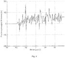
- FIGS. 4 and 5 how the method was tested and tested using the simulated lunar landing trajectories. Both pure simulations and comparisons between real and virtual images were used.
- the in the FIGS. 4 and 5 Curves shown show the accuracy achieved for a descent of a simulated lunar module of about 100 km altitude to about 5 km altitude. Shown in the FIGS. 4 and 5 the average positioning accuracies achieved in the test and the associated standard deviations.
Landscapes
- Engineering & Computer Science (AREA)
- Remote Sensing (AREA)
- Radar, Positioning & Navigation (AREA)
- Physics & Mathematics (AREA)
- General Physics & Mathematics (AREA)
- Automation & Control Theory (AREA)
- Theoretical Computer Science (AREA)
- Multimedia (AREA)
- Computer Vision & Pattern Recognition (AREA)
- Astronomy & Astrophysics (AREA)
- Signal Processing (AREA)
- Navigation (AREA)
- Processing Or Creating Images (AREA)
- Image Analysis (AREA)
- Length Measuring Devices By Optical Means (AREA)
- Traffic Control Systems (AREA)
Description
Die Erfindung betrifft Verfahren zur Positions- und Lagebestimmung einer Kamera gegenüber einer topografischen Karte mittels virtueller Referenzbilder.The invention relates to methods for determining the position and orientation of a camera relative to a topographic map by means of virtual reference images.
Für die Erkundung extremer Umgebungen, beispielsweise fremde Planeten oder auch Tiefseeregionen, werden verstärkt autonom agierende Fahrzeuge eingesetzt, die sich in ihrer Umgebung selbst lokalisieren müssen, um einen vorausgeplanten Zielort erreichen zu können. Eine Möglichkeit besteht dabei in einem Verfahren der eingangs genannten Art, das auf einer kamerabasierten Navigation anhand existierender topografischer Karten beruht. Derartige topografische Karten existieren auch für bisher nicht ausreichend erkundete Regionen, wie zum Beispiel den Meeresboden der Tiefsee oder planetare Oberflächen wie die von Mond und Mars. Insbesondere für den Mond und den Mars existieren aufgrund in der Vergangenheit durchgeführter Kartografierungsmissionen der amerikanischen und japanischen Raumfahrtagenturen NASA und JAXA detaillierte topografische Karten des gesamten Mondes und auch für den Mars, die sowohl Fotografien als auch Höhenreliefs beinhalten, die mittels Stereo oder Laserabstandsmessungen gewonnen wurden. Die Qualität des Kartenmaterials ist sehr hoch und geht insbesondere für Regionen wie die polaren Regionen des Mondes bis herunter zu einer Auflösung von einigen Metern.For the exploration of extreme environments, such as alien planets or deep-sea regions, increasingly autonomous vehicles are used, which must localize themselves in their environment in order to reach a pre-planned destination. One possibility consists in a method of the type mentioned, which is based on a camera-based navigation using existing topographic maps. Such topographical maps also exist for hitherto insufficiently explored regions, such as the deep seabed or planetary surfaces such as those of the moon and Mars. In particular, for the Moon and Mars, detailed mapping charts of the entire Moon are available based on mapping missions conducted in the past by the US and Japanese space agencies NASA and JAXA and also for Mars, which includes both photographs and elevation reliefs obtained by stereo or laser distance measurements. The quality of the map material is very high and goes down to a resolution of a few meters, especially for regions such as the polar regions of the moon.
Ein Landefahrzeug, das einen vorgegebenen Ort präzise treffen soll, muß während des Landevorganges seine Position und seine Lage ständig beobachten, um Abweichungen von einer geplanten Bahn korrigieren zu können. Da es außerhalb der Erde keine gängigen Navigationssysteme gibt, muss die Navigation anderweitig erfolgen. Bei einer angestrebten Genauigkeit von wenigen hundert Metern ist auch eine Navigation durch RADAR-Systeme von der Erde aus nicht möglich, und eine sichtgestützte Navigation anhand bekannter Merkmale auf der Planetenoberfläche ist die einzig verbleibende Möglichkeit. Dabei besteht die Herausforderung darin, bei der Abbildung einer planetaren Oberfläche mit Hilfe einer Kamera Merkmale zu extrahieren und wiederzuerkennen, deren räumliche Lage in Bezug zu einem Referenzsystem bekannt sind. Aus der Korrespondenz von zweidimensionalen Orten im Kamerabild und dreidimensionalen Orten im Referenzsystem lässt sich dann die Position und Lage des Kamerasystems bezüglich des Referenzsystems bestimmen.A landing craft, which is to hit a given location precisely, must constantly observe its position and its position during the landing process in order to be able to correct deviations from a planned course. Since there are no common navigation systems outside the earth, the navigation must be otherwise. With an accuracy of a few hundred meters, navigation through RADAR systems from Earth is not possible, and visual navigation using known features on the planet's surface is the only option left. The challenge is to extract and recognize features of a planetary surface with the help of a camera, the spatial position of which is known in relation to a reference system. From the correspondence of two-dimensional locations in the camera image and three-dimensional locations in the reference system, the position and position of the camera system with respect to the reference system can then be determined.
Ein Grundprinzip bereits bekannter Verfahren zur Navigation anhand von Karten besteht darin, dass mit Hilfe eines Kamerasystems Bilder des überflogenen Geländes aufgenommen werden und dass anhand der aufgenommenen Kamerabilder visuelle Merkmale extrahiert werden, die in dem für das Gelände verfügbaren Kartenmaterial wieder erkannt werden können. Aus der Zuordnung der zweidimensionalen Position der extrahierten Merkmale im Kamerabild und den 3D-Koordinaten der wiedererkannten Merkmale im Kartenmaterial zueinander kann dann die eigene Position und Lage ermittelt werden. Im Falle von Raumfahrzeugen wurde hierzu bereits vorgeschlagen, sich auf eine Bestimmung ihrer Position zu beschränken, da ihre Lage mit Hilfe von Sternenkameras genauer vermessen werden kann. Unterschiede zwischen den verschiedenen bekannten Verfahren bestehen vorwiegend in der Wahl der Merkmale, die aus den Kamerabildern extrahiert werden und die in dem Kartenmaterial wiederzuerkennen sind.A basic principle of previously known methods for navigation by means of maps is that with the aid of a camera system, images of the overflown terrain are taken and the recorded camera images are used to extract visual features that can be recognized in the map material available for the terrain. From the assignment of the two-dimensional position of the extracted features in the camera image and the 3D coordinates of the recognized features in the map material to each other then the own position and location can be determined. In the case of spacecraft, this has already been proposed to be limited to a determination of their position, since their position measured with the help of star cameras more accurate can be. Differences between the various known methods exist mainly in the choice of features which are extracted from the camera images and which are recognizable in the map material.
Ein im Wesentlichen für die Navigation auf der Mondoberfläche entwickeltes Verfahren, das in dem Artikel "
Bei einem als "LandStel" bezeichneten Verfahren, das unter anderem in dem Artikel "
Bei einem weiteren bekannten Verfahren werden die Merkmale mit Hilfe des sogenannten SIFT-Merkmalsoperators ermittelt und es werden ebenfalls Merkmale zwischen Fotografie und aktuellem Kamerabild verglichen. Die 3D-Daten werden dabei einer topografischen Karte entnommen. Bei einem anderen bekannten Verfahren werden kleine Bildausschnitte um bestimmte Punkte extrahiert, die mittels Korrelationsoperatoren in Karten des Geländes wiedererkannt werden sollen.In another known method, the features are determined using the so-called SIFT feature operator, and features between photography and the current camera image are also compared. The 3D data is taken from a topographic map. In another known method, small image sections are extracted around certain points which are to be recognized by means of correlation operators in maps of the terrain.
Neben diesen bildbasierten Ansätzen sind auch bereits Verfahren bekannt geworden, die Tiefendaten für Navigationszwecke vorschlagen und die die Daten eines LIDARs (Light Detection and Ranging) zugrundelegen.In addition to these image-based approaches, methods have already become known which propose depth data for navigation purposes and which are based on the data of a LIDAR (Light Detection and Ranging).
Den bildbasierten Ansätzen ist gemeinsam, dass entweder versucht wird, beleuchtungsunabhängige Operatoren zu entwickeln, wie sie der kraterbasierte Ansatz für sich beansprucht, oder aber dass Karten verwenden werden, die bereits ähnliche Beleuchtungsbedingungen aufweisen wie die Bilder, die zur Navigation zu erwarten sind.The image-based approaches have in common that either attempts to develop lighting-independent operators as claimed by the crater-based approach, or that will use maps that already have similar lighting conditions as the images to be expected for navigation.
Daneben sind auch bereits konkrete Verfahren für die Landung auf Himmelskörpern bekannt geworden. So beschreibt die
Aufgabe der Erfindung ist es, ein Verfahren der eingangs genannten Art so auszubilden, dass es eine sichtbasierte Navigation und die Verwendung computergrafischer Methoden zur Erzeugung einer Referenzdatenbank ermöglicht, die es erlaubt, einen Merkmalsextraktor auch dann zu verwenden, wenn dieser nicht beleuchtungsunabhängig ist oder unter Beleuchtungsvariation nicht robust genug ist.The object of the invention is to design a method of the type mentioned at the outset such that it permits sight-based navigation and the use of computer-graphic methods for generating a reference database, which allows a feature extractor to be used even if it is not independent of illumination or under illumination variation not robust enough.
Die Erfindung löst diese Aufgabe durch ein Verfahren, das in einem Offline-Prozess aus bestehenden topografischen Karten eine Merkmalsdatenbank erstellt und das diese anschließend in einem Online-Prozess zur Erkennung gesichteter Merkmale verwendet. Dazu werden erfindungsgemäß mit computergrafischen Methoden virtuelle Referenzbilder einer erwarteten Situation erzeugt, die mittels einer Merkmalsextraktion analysiert werden, und aus diesen wird ein Merkmalskatalog aus sichtbasierten Merkmalsvektoren und den dazugehörigen 3D-Koordinaten der lokalisierten Merkmale abgeleitet. Diese Daten werden in Form einer Modelldatenbank in einem Flugsystem hinterlegt und es erfolgt dann eine Navigation in der Nähe einer Referenztrajektorie für eine geplante Beleuchtungssituation.The invention solves this problem by a method that is in create a feature database from an existing topographic map offline process and then use it in an online face feature discovery process. For this purpose, according to the invention, computer-graphic methods are used to generate virtual reference images of an expected situation, which are analyzed by means of a feature extraction, and from these a catalog of features is made derived from sight-based feature vectors and the associated 3D coordinates of the localized features. These data are stored in the form of a model database in a flight system and then navigation takes place in the vicinity of a reference trajectory for a planned illumination situation.
Die Verwendung von kompletten Bildern und passiven Sensoren, wie einer Kamera, und die bei der Erfindung zum Einsatz gelangenden Techniken zur Merkmalsextraktion sind dabei weder in der Druckschrift
Die Erfindung macht dabei von der Tatsache Gebrauch, dass für viele mögliche Anwendungsfälle, wie beispielsweise für einen planetaren Landevorgang, Ort und Zeit des geplanten Überfluges bekannt sind. Ist zudem eine genaue topografische Karte des Überfluggebietes bekannt, so kann mit Hilfe des Verfahrens nach der Erfindung mittels computergrafischer Methoden anhand des Kartenmaterials und mit der Kenntnis der geplanten Überflugtrajektorie sowie dem geplanten Überflugzeitpunkt eine computergrafisch generierte Erwartungshaltung dessen errechnet werden, was die Kamera voraussichtlich abbilden wird. Auf diese Weise kann mit dem erfindungsgemäßen Verfahren in der Vorbereitung des Überfluges eine virtuelle Bildsequenz errechnet werden, zu der zusätzlich zu jedem Pixel im Bild eine korrespondierende 3D-Koordinate im Referenzkoordinatensystem hinterlegt wird.The invention makes use of the fact that for many possible applications, such as for a planetary landing process, the location and time of the planned overflight are known. If, in addition, an exact topographical map of the overflight area is known, a computergraphically generated expectation of what the camera is expected to map can be calculated with the aid of the method according to the invention by means of the map material and with the knowledge of the planned overflight trajectory and the planned overflight time , In this way, with the method according to the invention in the preparation of the overflight, a virtual image sequence can be calculated, to which a corresponding 3D coordinate in the reference coordinate system is stored in addition to each pixel in the image.
Die Vorberechnung einer erwarteten Bildsequenz stellt dabei einen Offline-Prozess dar, der zum erfindungsgemäß vorgesehenen Aufbau eines Merkmalskataloges dient, der während des tatsächlichen Überfluges zur Navigation verwendet wird. Die Grundidee des erfindungsgemäßen Verfahrens besteht daher in einer Aufteilung des gesamten Prozesses in der Weise, dass zunächst eine Merkmalsdatenbank erstellt wird und dass die so vorab erstellte Merkmalsdatenbank dann während des Flugbetriebes in einer Online-Anwendung eingesetzt wird. Obwohl das Verfahren nach der Erfindung Methoden bereits bestehender Verfahren verwendet, besteht seine Innovation darin, durch eine Verwendung computergrafischer Methoden zur Vor- und Aufbereitung des Kartenmaterials eine Vielzahl bereits existierender Merkmalsextraktoren zu verwenden, die an sich den Nachteil aufweisen, nicht beleuchtungsinvariant zu sein. Erst das Verfahren nach der Erfindung ermöglicht eine Verwendung bereits etablierter und zum Teil sehr robuster Methoden zur Merkmalsextraktion und Merkmalserkennung. Dieses hat beispielsweise für den Anwendungsfall einer Mondlandung gegenüber einer Kratererkennung den Vorteil, dass wirklich punktgenaue Merkmale verwendet werden, die im Bild und in der Karte sehr gut lokalisierbar sind und damit gegenüber einem kraterbasierten Ansatz eine deutliche Steigerung an erreichbarer Genauigkeit bieten. Die geringere erzielbare Genauigkeit eines kraterbasierten Ansatzes liegt dabei vor allem in dem Umstand, dass ein Krater kein regelmäßiger Körper mit scharf umrissenen Strukturen ist und sich daher auch seine Position bezüglich des vorliegenden Kartenmaterials nur ungefähr definieren lässt. Zusätzlich führt bei kraterbasierten Verfahren eine Änderung der Beleuchtungsbedingungen zu einer geringfügigen Verschiebung der detektierten Kraterpositionen, so dass das mit der vorliegenden Erfindung realisierte Verfahren auch für kraterbasierte Verfahren von Vorteil wäre.The precalculation of an expected image sequence represents an offline process, which serves for the inventively provided structure of a feature catalog, which is used during the actual overflight for navigation. The basic idea of the method according to the invention therefore consists in a division of the entire process in such a way that first a feature database is created and that the feature database thus created in advance is then used during flight operation in an online application. Although the method according to the invention uses methods of already existing methods, its innovation consists in using a multiplicity of already existing feature extractors, which in themselves have the disadvantage of not being invariable to illumination, by using computer graphics methods for preparing and processing the card material. Only the method according to the invention makes it possible to use already established and sometimes very robust methods for feature extraction and feature recognition. This has, for example, for the application of a moon landing over a crater recognition the advantage that really accurate features are used, which are very well localized in the image and in the map and thus offer over a crater-based approach a significant increase in achievable accuracy. The lower achievable accuracy of a crater-based approach lies in the fact that a crater is not a regular body with sharply outlined structures and therefore can only roughly define its position with respect to the present map material. In addition, in crater-based methods, a change in illumination conditions results in a slight shift in the detected crater positions, so that the method realized with the present invention would also be advantageous for crater-based methods.
Nachfolgend soll das Verfahren gemäß der Erfindung anhand der Zeichnung näher erläutert werden. Es zeigen
- Fig. 1
- den prinzipiellen Ablauf des Offline-Prozesses zur Erstellung einer Merkmalsdatenbank,
- Fig. 2
- den prinzipiellen Ablauf des Online-Prozesses zur Positions- und Lagebestimmung einer Kamera gegenüber einer Referenzkarte,
- Fig. 3
- die Zuordnung von Merkmalen zwischen einem virtuellen Bild und einem realen Bild,
- Fig. 4
- die mittlere Positionsgenauigkeit als Ergebnis einer simulierten Testlandung von 100 km bis auf 5 km Höhe anhand realer Bilder einer robotischen Testanlage.
- Fig. 5
- die Standardabweichung der Positionierfehler einer simulierten
Testlandung von 100 km bis auf 5 km Höhe anhand realer Bilder einer robotischen Testanlage.
- Fig. 1
- the basic process of the offline process for creating a feature database,
- Fig. 2
- the basic sequence of the online process for determining the position and orientation of a camera relative to a reference card,
- Fig. 3
- the assignment of features between a virtual image and a real image,
- Fig. 4
- the mean position accuracy as a result of a simulated test landing from 100 km to 5 km altitude using real images of a robotic test facility.
- Fig. 5
- the standard deviation of the positioning errors of a simulated test landing from 100 km to 5 km altitude using real images of a robotic test facility.
Die in
Diese Erstellung eines lokalen Modells kann deshalb notwendig sein, als das gesamte zu überfliegende Gebiet möglicherweise eine zu große Datenmenge beinhaltet. Für eine spezielle Kameraposition und Lage wird das lokale Modell zunächst als 3D-Modell 7 repräsentiert und, sofern vorhanden, mit einer sogenannten Albedo-Karte versehen, die die Reflektionseigenschaften der Oberfläche repräsentiert. Dabei sind gegebenenfalls Fehler in der Karte zu korrigieren und Lücken zu interpolieren.This creation of a local model may be necessary because the entire area to be overflow may contain too much data. For a specific camera position and location, the local model is first represented as a
Anhand des ursprünglichen Ausgangskartenmaterials wird dann eine lokale Karte erstellt. Hierbei handelt es sich um Höhenkarten, deren Grauwerte unterschiedlichen Höhen entsprechen. In diesem lokalen Modell kann virtuell eine Kamera an einer erwarteten Position platziert werden und ein virtuelles Bild, sowie eine virtuelle Tiefenkarte kann daraus erstellt werden.Based on the original source card material, a local map is created. These are height maps whose gray values correspond to different heights. In this local model, a virtual camera can be placed at an expected position and a virtual image, as well as a virtual depth map can be created from it.
Die Übereinstimmung kann in Abhängigkeit des zur Verfügung stehenden Kartenmaterials so ähnlich sein, dass Bildmerkmale 7, die im virtuellen Bild 6 errechnet wurden, ohne Mühe im realen Kamerabild wiedererkannt werden können. Diese Merkmale werden in einer Datenbank 8 abgelegt und bestehen aus einem Merkmalsvektor (in Abhängigkeit des verwendeten Merkmalsextraktors), sowie den dazugehörigen 3D-Koordinaten im Referenzsystem (beispielsweise Mondkoordinaten).The match can be so similar depending on the available map material that image features 7, which were calculated in the
Für die Merkmalserkennung werden zur Vereinfachung nicht alle in der Merkmalsdatenbank 8 vorliegenden Merkmale mit den in den Bildern gefundenen verglichen, sondern nur diejenigen Merkmale ausgewählt, die nach Berücksichtigung der bisher durchgeführten Positions- und Lageschätzung in Frage kommen können. So kann eine große Anzahl gar nicht sichtbarer Merkmale bereits im Vorfeld ausgeschlossen werden, da sie beispielsweise zu Kartenbereichen gehören, die zu weit entfernt sind. Die Listen korrespondierender 2D-Orte aus dem aktuellen Kamerabild und 3D-Koordinaten aus den Höhenkarten können nun auf zwei Weisen die Position und Lage des Kamerasystems 10 bezüglich der Referenzkarte bestimmt werden 18. Entweder durch ein Optimierungsverfahren, das direkt die Kamera-Position und die Lage bestimmt, oder aber es wird ein iterativer sogenannter Kalman-Filter verwendet, der den Vorteil bietet, noch weitere Messungen anderer Sensoren 19 berücksichtigen zu können. Für die Vorauswahl 9 der relevanten Merkmale im nächsten Zeittakt aus der Merkmalsdatenbank 8 wird dann entweder direkt die so gewonnene Positions- und Lageinformation genutzt oder es wird eine Initialisierung von außen vorgegeben.For the feature recognition, not all of the features present in the
Die
Abschließend ist in den
Claims (4)
- A method for determining the position and orientation of a camera in respect of a topographical map, characterized in that
as part of an offline process a feature database (8) is generated from existing topographical maps, wherein computer-graphical models are used to produce virtual reference images of an anticipated situation, which images are analysed by means of feature extraction (11), and wherein the feature database (8) from this is derived from sight-based feature vectors and the associated 3D coordinates of the localized features and
the feature database (8) is then used in an online process to identify features that have been seen. - The method according to claim 1, characterized in that it is used on board a flight system.
- The method according to claim 2, characterized in that the sight-based feature vectors and the associated 3D coordinates are stored in the flight system in the form of a model database (8) and that navigation takes place close to a reference trajectory and with a planned lighting situation (3).
- The method according to one of claims 1 to 3, characterized in that the virtual reference images (6) comprise a sequence in which for each pixel a corresponding 3D coordinate is stored in a reference coordinate system.
Applications Claiming Priority (1)
| Application Number | Priority Date | Filing Date | Title |
|---|---|---|---|
| DE102014003284.1A DE102014003284A1 (en) | 2014-03-05 | 2014-03-05 | Method for position and position determination using virtual reference images |
Publications (2)
| Publication Number | Publication Date |
|---|---|
| EP2916106A1 EP2916106A1 (en) | 2015-09-09 |
| EP2916106B1 true EP2916106B1 (en) | 2018-06-13 |
Family
ID=52630229
Family Applications (1)
| Application Number | Title | Priority Date | Filing Date |
|---|---|---|---|
| EP15157533.9A Active EP2916106B1 (en) | 2014-03-05 | 2015-03-04 | Method for determining position and attitude by means of virtual reference images |
Country Status (6)
| Country | Link |
|---|---|
| US (1) | US9857178B2 (en) |
| EP (1) | EP2916106B1 (en) |
| JP (1) | JP6023831B2 (en) |
| CA (1) | CA2883862C (en) |
| DE (1) | DE102014003284A1 (en) |
| RU (1) | RU2613735C2 (en) |
Cited By (1)
| Publication number | Priority date | Publication date | Assignee | Title |
|---|---|---|---|---|
| US11460302B2 (en) | 2018-06-19 | 2022-10-04 | Safran Vectronix Ag | Terrestrial observation device having location determination functionality |
Families Citing this family (13)
| Publication number | Priority date | Publication date | Assignee | Title |
|---|---|---|---|---|
| DE102016101455A1 (en) * | 2016-01-27 | 2017-07-27 | Terraloupe Gmbh | Positioning Device and Earth Surface Model Database |
| RU2615587C9 (en) * | 2016-03-18 | 2017-08-02 | Общество с ограниченной ответственностью "ЛЕ ТАЛО РОБОТИКС" | Method of accurate landing of unmanned aircraft |
| JP6903022B2 (en) * | 2018-02-06 | 2021-07-14 | 三菱電機株式会社 | Water operation maintenance integrated system |
| CN109084769A (en) * | 2018-06-28 | 2018-12-25 | 上海卫星工程研究所 | The localization method of martian surface image noncooperative target |
| RU2692350C1 (en) * | 2018-07-19 | 2019-06-24 | Федеральное государственное бюджетное учреждение науки Институт астрономии Российской академии наук | Method for high-accuracy positioning of apparatus on moon surface and device for its implementation |
| WO2020103020A1 (en) | 2018-11-21 | 2020-05-28 | 广州极飞科技有限公司 | Surveying sample point planning method and apparatus, control terminal, and storage medium |
| CN110047115B (en) * | 2019-03-26 | 2021-11-16 | 珠海格力电器股份有限公司 | Star image shooting method and device, computer equipment and storage medium |
| CN110501021B (en) * | 2019-08-27 | 2021-01-29 | 中国人民解放军国防科技大学 | Odometer estimation method and system based on camera and laser radar fusion |
| CN111351506B (en) * | 2020-03-20 | 2022-05-24 | 上海航天控制技术研究所 | Mars visible light target characteristic accurate simulation method based on 3D printing |
| CN111536982B (en) * | 2020-05-06 | 2023-09-19 | 北京工业大学 | Optical navigation image generation method of asteroid detector under poor illumination condition |
| CN111982129B (en) * | 2020-08-24 | 2022-03-08 | 哈尔滨工业大学 | Comprehensive global path planning method based on lunar surface digital elevation map |
| CN112486817B (en) * | 2020-11-27 | 2023-11-07 | 北京百度网讯科技有限公司 | Evaluation method, device, equipment and storage medium for data update |
| CN114485679B (en) * | 2022-01-18 | 2024-05-07 | 北京理工大学 | Planetary landing sparse feature virtual derivative autonomous navigation method |
Citations (2)
| Publication number | Priority date | Publication date | Assignee | Title |
|---|---|---|---|---|
| US20130230214A1 (en) * | 2012-03-02 | 2013-09-05 | Qualcomm Incorporated | Scene structure-based self-pose estimation |
| EP2687817A2 (en) * | 2012-07-19 | 2014-01-22 | Honeywell International Inc. | Method of correlating images with terrain elevation maps for navigation |
Family Cites Families (16)
| Publication number | Priority date | Publication date | Assignee | Title |
|---|---|---|---|---|
| US3784968A (en) | 1970-05-29 | 1974-01-08 | J Brosow | Navigation system |
| DE3110691C2 (en) | 1981-03-19 | 1985-07-18 | Messerschmitt-Bölkow-Blohm GmbH, 8012 Ottobrunn | Directional missile navigation system |
| AU621584B2 (en) | 1988-01-28 | 1992-03-19 | Heiko Schmidt V. Braun | Large scale ariel mapping |
| RU2044273C1 (en) * | 1989-01-12 | 1995-09-20 | Шмидт ф.Браун Др.Хайко | Method of making large-scale parameter map of multi-dimensional structure of environment and photographic aeroplane |
| DE3939731A1 (en) | 1989-12-01 | 1991-06-06 | Dornier Luftfahrt | AUTONOMOUS LANDING SYSTEM |
| JPH06251126A (en) * | 1993-02-25 | 1994-09-09 | Hitachi Ltd | Image synthesizing method |
| DE19521600A1 (en) | 1995-06-14 | 1996-12-19 | Bodenseewerk Geraetetech | Landing procedures for unmanned aerial vehicles |
| RU2375756C2 (en) * | 2005-06-06 | 2009-12-10 | Томтом Интернэшнл Б.В. | Navigation device with information received from camera |
| ES2404164T3 (en) | 2005-06-06 | 2013-05-24 | Tomtom International B.V. | Navigation device with information camera |
| RU2353902C2 (en) * | 2007-05-11 | 2009-04-27 | Открытое акционерное общество "Ракетно-космическая корпорация "Энергия" имени С.П. Королева" | Method for determination of geographic coordinates of object images on planet surface during shooting from manned spacecraft |
| US8532328B2 (en) * | 2007-08-16 | 2013-09-10 | The Boeing Company | Methods and apparatus for planetary navigation |
| DE102008064712B4 (en) | 2008-05-08 | 2013-02-28 | Deutsches Zentrum für Luft- und Raumfahrt e.V. | Landing aid device for helicopter, has sensor unit with sensors for detecting relative position between landing platform and helicopter, where sensors are arranged for detecting relative velocity of landing platform against helicopter |
| US8355579B2 (en) | 2009-05-20 | 2013-01-15 | The United States Of America As Represented By The Administrator Of The National Aeronautics And Space Administration | Automatic extraction of planetary image features |
| DE102009036518B4 (en) | 2009-08-07 | 2014-09-25 | Deutsches Zentrum für Luft- und Raumfahrt e.V. | Spacecraft and method of performing a landing thereof |
| DE102010051561A1 (en) | 2010-11-18 | 2012-05-24 | Rheinmetall Defence Electronics Gmbh | Automated landing of unmanned aerial vehicles |
| GB2512242A (en) * | 2012-01-18 | 2014-09-24 | Logos Technologies Llc | Method, device, and system for computing a spherical projection image based on two-dimensional images |
-
2014
- 2014-03-05 DE DE102014003284.1A patent/DE102014003284A1/en not_active Withdrawn
-
2015
- 2015-03-04 EP EP15157533.9A patent/EP2916106B1/en active Active
- 2015-03-04 RU RU2015107561A patent/RU2613735C2/en active
- 2015-03-04 CA CA2883862A patent/CA2883862C/en active Active
- 2015-03-04 US US14/638,128 patent/US9857178B2/en active Active
- 2015-03-04 JP JP2015042462A patent/JP6023831B2/en active Active
Patent Citations (2)
| Publication number | Priority date | Publication date | Assignee | Title |
|---|---|---|---|---|
| US20130230214A1 (en) * | 2012-03-02 | 2013-09-05 | Qualcomm Incorporated | Scene structure-based self-pose estimation |
| EP2687817A2 (en) * | 2012-07-19 | 2014-01-22 | Honeywell International Inc. | Method of correlating images with terrain elevation maps for navigation |
Non-Patent Citations (1)
| Title |
|---|
| TALLURI R ET AL: "IMAGE/MAP CORRESPONDENCE FOR MOBILE ROBOT SELF-LOCATION USING COMPUTER GRAPHICS", IEEE TRANSACTIONS ON PATTERN ANALYSIS AND MACHINE INTELLIGENCE, IEEE COMPUTER SOCIETY, USA, vol. 15, no. 6, 1 June 1993 (1993-06-01), pages 597 - 601, XP000369962, ISSN: 0162-8828, DOI: 10.1109/34.216729 * |
Cited By (1)
| Publication number | Priority date | Publication date | Assignee | Title |
|---|---|---|---|---|
| US11460302B2 (en) | 2018-06-19 | 2022-10-04 | Safran Vectronix Ag | Terrestrial observation device having location determination functionality |
Also Published As
| Publication number | Publication date |
|---|---|
| RU2613735C2 (en) | 2017-03-21 |
| US9857178B2 (en) | 2018-01-02 |
| CA2883862A1 (en) | 2015-09-05 |
| JP6023831B2 (en) | 2016-11-09 |
| RU2015107561A (en) | 2016-09-27 |
| US20150253140A1 (en) | 2015-09-10 |
| DE102014003284A1 (en) | 2015-09-10 |
| CA2883862C (en) | 2021-01-05 |
| JP2015170364A (en) | 2015-09-28 |
| EP2916106A1 (en) | 2015-09-09 |
Similar Documents
| Publication | Publication Date | Title |
|---|---|---|
| EP2916106B1 (en) | Method for determining position and attitude by means of virtual reference images | |
| EP2927844A1 (en) | 3d object position and pose estimation | |
| DE102015011914B4 (en) | Contour line measuring device and robotic system | |
| EP3596570B2 (en) | Method for checking the electrical continuity of a lightning conductor of a wind turbine | |
| DE102011016521B4 (en) | Method for flight guidance of an aircraft to a specified target object and flight guidance system | |
| DE102007054950B4 (en) | Method for supporting the automatic navigation of a low-flying missile | |
| EP2381208B1 (en) | Method for determining positional data of a target object in a reference system | |
| Andert et al. | Lidar-aided camera feature tracking and visual slam for spacecraft low-orbit navigation and planetary landing | |
| DE102011010987A1 (en) | Navigation method for a missile | |
| EP2381207B1 (en) | 3D targeting and target designation from IR data | |
| DE102019215903A1 (en) | Method and device for generating training data for a recognition model for recognizing objects in sensor data of a sensor, in particular of a vehicle, method for training and method for actuation | |
| DE102019216548A1 (en) | Method and mobile detection device for the detection of infrastructure elements of an underground line network | |
| DE102020129743A1 (en) | DEVICE AND METHOD FOR MEASUREMENT, INSPECTION OR PROCESSING OF OBJECTS | |
| AT511460A4 (en) | METHOD FOR DETERMINING THE POSITION OF AN AIRCRAFT | |
| DE102007018187B4 (en) | Method for optimizing the image-based automatic navigation of an unmanned missile | |
| DE102013000410A1 (en) | Method for navigating intrinsically locomotion enabled platform relative to three-dimensional object e.g. cylinder, involves moving platform along structure of object with minimum distance based on aligned orientation to structure of object | |
| EP4145238A1 (en) | Method for controlling an unmanned aerial vehicle for an inspection flight for inspecting an object, and unmanned inspection aerial vehicle | |
| WO2007090557A2 (en) | Method for generating an environmental image | |
| DE19735175A1 (en) | Digital detection of spatial scenes or sets for determining object co-ordinates | |
| EP2940624B1 (en) | Three-dimensional virtual model of an environment for applications for determining positions | |
| DE102021123503A1 (en) | Determination of an absolute initial position of a vehicle | |
| Yan et al. | A holistic vision-based hazard detection framework for asteroid landings | |
| Hößler et al. | Automated traffic analysis in aerial images | |
| Asatryan et al. | A Rational Approach to the Problem of Accurate UAV Landing Using Intelligent Image Processing Methods | |
| Cao et al. | Autonomous Landing Spot Detection for Unmanned Aerial Vehicles Based on Monocular Vision |
Legal Events
| Date | Code | Title | Description |
|---|---|---|---|
| PUAI | Public reference made under article 153(3) epc to a published international application that has entered the european phase |
Free format text: ORIGINAL CODE: 0009012 |
|
| AK | Designated contracting states |
Kind code of ref document: A1 Designated state(s): AL AT BE BG CH CY CZ DE DK EE ES FI FR GB GR HR HU IE IS IT LI LT LU LV MC MK MT NL NO PL PT RO RS SE SI SK SM TR |
|
| AX | Request for extension of the european patent |
Extension state: BA ME |
|
| 17P | Request for examination filed |
Effective date: 20160304 |
|
| RBV | Designated contracting states (corrected) |
Designated state(s): AL AT BE BG CH CY CZ DE DK EE ES FI FR GB GR HR HU IE IS IT LI LT LU LV MC MK MT NL NO PL PT RO RS SE SI SK SM TR |
|
| 17Q | First examination report despatched |
Effective date: 20160819 |
|
| STAA | Information on the status of an ep patent application or granted ep patent |
Free format text: STATUS: EXAMINATION IS IN PROGRESS |
|
| RAP1 | Party data changed (applicant data changed or rights of an application transferred) |
Owner name: AIRBUS DEFENCE AND SPACE GMBH |
|
| RIC1 | Information provided on ipc code assigned before grant |
Ipc: G06T 7/70 20170101ALI20171213BHEP Ipc: G01C 21/20 20060101AFI20171213BHEP |
|
| GRAP | Despatch of communication of intention to grant a patent |
Free format text: ORIGINAL CODE: EPIDOSNIGR1 |
|
| STAA | Information on the status of an ep patent application or granted ep patent |
Free format text: STATUS: GRANT OF PATENT IS INTENDED |
|
| INTG | Intention to grant announced |
Effective date: 20180123 |
|
| GRAS | Grant fee paid |
Free format text: ORIGINAL CODE: EPIDOSNIGR3 |
|
| GRAA | (expected) grant |
Free format text: ORIGINAL CODE: 0009210 |
|
| STAA | Information on the status of an ep patent application or granted ep patent |
Free format text: STATUS: THE PATENT HAS BEEN GRANTED |
|
| AK | Designated contracting states |
Kind code of ref document: B1 Designated state(s): AL AT BE BG CH CY CZ DE DK EE ES FI FR GB GR HR HU IE IS IT LI LT LU LV MC MK MT NL NO PL PT RO RS SE SI SK SM TR |
|
| REG | Reference to a national code |
Ref country code: GB Ref legal event code: FG4D Free format text: NOT ENGLISH |
|
| REG | Reference to a national code |
Ref country code: CH Ref legal event code: EP Ref country code: AT Ref legal event code: REF Ref document number: 1008961 Country of ref document: AT Kind code of ref document: T Effective date: 20180615 |
|
| REG | Reference to a national code |
Ref country code: IE Ref legal event code: FG4D Free format text: LANGUAGE OF EP DOCUMENT: GERMAN |
|
| REG | Reference to a national code |
Ref country code: DE Ref legal event code: R096 Ref document number: 502015004620 Country of ref document: DE |
|
| REG | Reference to a national code |
Ref country code: NL Ref legal event code: MP Effective date: 20180613 |
|
| REG | Reference to a national code |
Ref country code: LT Ref legal event code: MG4D |
|
| PG25 | Lapsed in a contracting state [announced via postgrant information from national office to epo] |
Ref country code: CY Free format text: LAPSE BECAUSE OF FAILURE TO SUBMIT A TRANSLATION OF THE DESCRIPTION OR TO PAY THE FEE WITHIN THE PRESCRIBED TIME-LIMIT Effective date: 20180613 Ref country code: ES Free format text: LAPSE BECAUSE OF FAILURE TO SUBMIT A TRANSLATION OF THE DESCRIPTION OR TO PAY THE FEE WITHIN THE PRESCRIBED TIME-LIMIT Effective date: 20180613 Ref country code: LT Free format text: LAPSE BECAUSE OF FAILURE TO SUBMIT A TRANSLATION OF THE DESCRIPTION OR TO PAY THE FEE WITHIN THE PRESCRIBED TIME-LIMIT Effective date: 20180613 Ref country code: BG Free format text: LAPSE BECAUSE OF FAILURE TO SUBMIT A TRANSLATION OF THE DESCRIPTION OR TO PAY THE FEE WITHIN THE PRESCRIBED TIME-LIMIT Effective date: 20180913 Ref country code: FI Free format text: LAPSE BECAUSE OF FAILURE TO SUBMIT A TRANSLATION OF THE DESCRIPTION OR TO PAY THE FEE WITHIN THE PRESCRIBED TIME-LIMIT Effective date: 20180613 Ref country code: NO Free format text: LAPSE BECAUSE OF FAILURE TO SUBMIT A TRANSLATION OF THE DESCRIPTION OR TO PAY THE FEE WITHIN THE PRESCRIBED TIME-LIMIT Effective date: 20180913 Ref country code: SE Free format text: LAPSE BECAUSE OF FAILURE TO SUBMIT A TRANSLATION OF THE DESCRIPTION OR TO PAY THE FEE WITHIN THE PRESCRIBED TIME-LIMIT Effective date: 20180613 |
|
| PG25 | Lapsed in a contracting state [announced via postgrant information from national office to epo] |
Ref country code: GR Free format text: LAPSE BECAUSE OF FAILURE TO SUBMIT A TRANSLATION OF THE DESCRIPTION OR TO PAY THE FEE WITHIN THE PRESCRIBED TIME-LIMIT Effective date: 20180914 Ref country code: LV Free format text: LAPSE BECAUSE OF FAILURE TO SUBMIT A TRANSLATION OF THE DESCRIPTION OR TO PAY THE FEE WITHIN THE PRESCRIBED TIME-LIMIT Effective date: 20180613 Ref country code: HR Free format text: LAPSE BECAUSE OF FAILURE TO SUBMIT A TRANSLATION OF THE DESCRIPTION OR TO PAY THE FEE WITHIN THE PRESCRIBED TIME-LIMIT Effective date: 20180613 Ref country code: RS Free format text: LAPSE BECAUSE OF FAILURE TO SUBMIT A TRANSLATION OF THE DESCRIPTION OR TO PAY THE FEE WITHIN THE PRESCRIBED TIME-LIMIT Effective date: 20180613 |
|
| PG25 | Lapsed in a contracting state [announced via postgrant information from national office to epo] |
Ref country code: NL Free format text: LAPSE BECAUSE OF FAILURE TO SUBMIT A TRANSLATION OF THE DESCRIPTION OR TO PAY THE FEE WITHIN THE PRESCRIBED TIME-LIMIT Effective date: 20180613 |
|
| PG25 | Lapsed in a contracting state [announced via postgrant information from national office to epo] |
Ref country code: CZ Free format text: LAPSE BECAUSE OF FAILURE TO SUBMIT A TRANSLATION OF THE DESCRIPTION OR TO PAY THE FEE WITHIN THE PRESCRIBED TIME-LIMIT Effective date: 20180613 Ref country code: PL Free format text: LAPSE BECAUSE OF FAILURE TO SUBMIT A TRANSLATION OF THE DESCRIPTION OR TO PAY THE FEE WITHIN THE PRESCRIBED TIME-LIMIT Effective date: 20180613 Ref country code: SK Free format text: LAPSE BECAUSE OF FAILURE TO SUBMIT A TRANSLATION OF THE DESCRIPTION OR TO PAY THE FEE WITHIN THE PRESCRIBED TIME-LIMIT Effective date: 20180613 Ref country code: RO Free format text: LAPSE BECAUSE OF FAILURE TO SUBMIT A TRANSLATION OF THE DESCRIPTION OR TO PAY THE FEE WITHIN THE PRESCRIBED TIME-LIMIT Effective date: 20180613 Ref country code: IS Free format text: LAPSE BECAUSE OF FAILURE TO SUBMIT A TRANSLATION OF THE DESCRIPTION OR TO PAY THE FEE WITHIN THE PRESCRIBED TIME-LIMIT Effective date: 20181013 Ref country code: EE Free format text: LAPSE BECAUSE OF FAILURE TO SUBMIT A TRANSLATION OF THE DESCRIPTION OR TO PAY THE FEE WITHIN THE PRESCRIBED TIME-LIMIT Effective date: 20180613 |
|
| REG | Reference to a national code |
Ref country code: CH Ref legal event code: PK Free format text: BERICHTIGUNGEN |
|
| RIC2 | Information provided on ipc code assigned after grant |
Ipc: G01C 21/20 20060101AFI20171213BHEP Ipc: G06T 7/70 20170101ALI20171213BHEP |
|
| PG25 | Lapsed in a contracting state [announced via postgrant information from national office to epo] |
Ref country code: SM Free format text: LAPSE BECAUSE OF FAILURE TO SUBMIT A TRANSLATION OF THE DESCRIPTION OR TO PAY THE FEE WITHIN THE PRESCRIBED TIME-LIMIT Effective date: 20180613 |
|
| REG | Reference to a national code |
Ref country code: DE Ref legal event code: R097 Ref document number: 502015004620 Country of ref document: DE |
|
| PLBE | No opposition filed within time limit |
Free format text: ORIGINAL CODE: 0009261 |
|
| STAA | Information on the status of an ep patent application or granted ep patent |
Free format text: STATUS: NO OPPOSITION FILED WITHIN TIME LIMIT |
|
| 26N | No opposition filed |
Effective date: 20190314 |
|
| PG25 | Lapsed in a contracting state [announced via postgrant information from national office to epo] |
Ref country code: SI Free format text: LAPSE BECAUSE OF FAILURE TO SUBMIT A TRANSLATION OF THE DESCRIPTION OR TO PAY THE FEE WITHIN THE PRESCRIBED TIME-LIMIT Effective date: 20180613 Ref country code: DK Free format text: LAPSE BECAUSE OF FAILURE TO SUBMIT A TRANSLATION OF THE DESCRIPTION OR TO PAY THE FEE WITHIN THE PRESCRIBED TIME-LIMIT Effective date: 20180613 |
|
| PG25 | Lapsed in a contracting state [announced via postgrant information from national office to epo] |
Ref country code: MC Free format text: LAPSE BECAUSE OF FAILURE TO SUBMIT A TRANSLATION OF THE DESCRIPTION OR TO PAY THE FEE WITHIN THE PRESCRIBED TIME-LIMIT Effective date: 20180613 |
|
| REG | Reference to a national code |
Ref country code: CH Ref legal event code: PL |
|
| PG25 | Lapsed in a contracting state [announced via postgrant information from national office to epo] |
Ref country code: LU Free format text: LAPSE BECAUSE OF NON-PAYMENT OF DUE FEES Effective date: 20190304 Ref country code: AL Free format text: LAPSE BECAUSE OF FAILURE TO SUBMIT A TRANSLATION OF THE DESCRIPTION OR TO PAY THE FEE WITHIN THE PRESCRIBED TIME-LIMIT Effective date: 20180613 |
|
| REG | Reference to a national code |
Ref country code: BE Ref legal event code: MM Effective date: 20190331 |
|
| PG25 | Lapsed in a contracting state [announced via postgrant information from national office to epo] |
Ref country code: IE Free format text: LAPSE BECAUSE OF NON-PAYMENT OF DUE FEES Effective date: 20190304 Ref country code: CH Free format text: LAPSE BECAUSE OF NON-PAYMENT OF DUE FEES Effective date: 20190331 Ref country code: LI Free format text: LAPSE BECAUSE OF NON-PAYMENT OF DUE FEES Effective date: 20190331 |
|
| PG25 | Lapsed in a contracting state [announced via postgrant information from national office to epo] |
Ref country code: BE Free format text: LAPSE BECAUSE OF NON-PAYMENT OF DUE FEES Effective date: 20190331 |
|
| PG25 | Lapsed in a contracting state [announced via postgrant information from national office to epo] |
Ref country code: TR Free format text: LAPSE BECAUSE OF FAILURE TO SUBMIT A TRANSLATION OF THE DESCRIPTION OR TO PAY THE FEE WITHIN THE PRESCRIBED TIME-LIMIT Effective date: 20180613 |
|
| PG25 | Lapsed in a contracting state [announced via postgrant information from national office to epo] |
Ref country code: PT Free format text: LAPSE BECAUSE OF FAILURE TO SUBMIT A TRANSLATION OF THE DESCRIPTION OR TO PAY THE FEE WITHIN THE PRESCRIBED TIME-LIMIT Effective date: 20181015 Ref country code: MT Free format text: LAPSE BECAUSE OF FAILURE TO SUBMIT A TRANSLATION OF THE DESCRIPTION OR TO PAY THE FEE WITHIN THE PRESCRIBED TIME-LIMIT Effective date: 20180613 |
|
| REG | Reference to a national code |
Ref country code: AT Ref legal event code: MM01 Ref document number: 1008961 Country of ref document: AT Kind code of ref document: T Effective date: 20200304 |
|
| PG25 | Lapsed in a contracting state [announced via postgrant information from national office to epo] |
Ref country code: HU Free format text: LAPSE BECAUSE OF FAILURE TO SUBMIT A TRANSLATION OF THE DESCRIPTION OR TO PAY THE FEE WITHIN THE PRESCRIBED TIME-LIMIT; INVALID AB INITIO Effective date: 20150304 |
|
| PG25 | Lapsed in a contracting state [announced via postgrant information from national office to epo] |
Ref country code: AT Free format text: LAPSE BECAUSE OF NON-PAYMENT OF DUE FEES Effective date: 20200304 |
|
| PG25 | Lapsed in a contracting state [announced via postgrant information from national office to epo] |
Ref country code: MK Free format text: LAPSE BECAUSE OF FAILURE TO SUBMIT A TRANSLATION OF THE DESCRIPTION OR TO PAY THE FEE WITHIN THE PRESCRIBED TIME-LIMIT Effective date: 20180613 |
|
| PGFP | Annual fee paid to national office [announced via postgrant information from national office to epo] |
Ref country code: FR Payment date: 20230324 Year of fee payment: 9 |
|
| PGFP | Annual fee paid to national office [announced via postgrant information from national office to epo] |
Ref country code: IT Payment date: 20230328 Year of fee payment: 9 |
|
| PGFP | Annual fee paid to national office [announced via postgrant information from national office to epo] |
Ref country code: DE Payment date: 20240320 Year of fee payment: 10 Ref country code: GB Payment date: 20240320 Year of fee payment: 10 |