EP2913256B1 - Vehicle - Google Patents
Vehicle Download PDFInfo
- Publication number
- EP2913256B1 EP2913256B1 EP13849340.8A EP13849340A EP2913256B1 EP 2913256 B1 EP2913256 B1 EP 2913256B1 EP 13849340 A EP13849340 A EP 13849340A EP 2913256 B1 EP2913256 B1 EP 2913256B1
- Authority
- EP
- European Patent Office
- Prior art keywords
- axis
- resisting force
- body frame
- force change
- turn
- Prior art date
- Legal status (The legal status is an assumption and is not a legal conclusion. Google has not performed a legal analysis and makes no representation as to the accuracy of the status listed.)
- Active
Links
- 230000007246 mechanism Effects 0.000 claims description 325
- 230000008859 change Effects 0.000 claims description 236
- 230000035939 shock Effects 0.000 claims description 67
- 239000012530 fluid Substances 0.000 claims description 37
- 239000011553 magnetic fluid Substances 0.000 claims description 9
- 238000006073 displacement reaction Methods 0.000 claims description 7
- 238000004891 communication Methods 0.000 claims description 6
- 230000000717 retained effect Effects 0.000 claims description 2
- 238000010008 shearing Methods 0.000 claims description 2
- 239000006096 absorbing agent Substances 0.000 description 15
- 230000002452 interceptive effect Effects 0.000 description 6
- 238000013016 damping Methods 0.000 description 4
- 238000005516 engineering process Methods 0.000 description 3
- 230000009471 action Effects 0.000 description 2
- 238000010276 construction Methods 0.000 description 2
- 230000000694 effects Effects 0.000 description 2
- 230000004048 modification Effects 0.000 description 2
- 238000012986 modification Methods 0.000 description 2
- 238000005192 partition Methods 0.000 description 2
- 230000002265 prevention Effects 0.000 description 2
- 230000001960 triggered effect Effects 0.000 description 2
- 230000005540 biological transmission Effects 0.000 description 1
- 230000014509 gene expression Effects 0.000 description 1
- 230000002093 peripheral effect Effects 0.000 description 1
Images


Classifications
-
- B—PERFORMING OPERATIONS; TRANSPORTING
- B62—LAND VEHICLES FOR TRAVELLING OTHERWISE THAN ON RAILS
- B62D—MOTOR VEHICLES; TRAILERS
- B62D9/00—Steering deflectable wheels not otherwise provided for
- B62D9/02—Steering deflectable wheels not otherwise provided for combined with means for inwardly inclining vehicle body on bends
-
- B—PERFORMING OPERATIONS; TRANSPORTING
- B62—LAND VEHICLES FOR TRAVELLING OTHERWISE THAN ON RAILS
- B62K—CYCLES; CYCLE FRAMES; CYCLE STEERING DEVICES; RIDER-OPERATED TERMINAL CONTROLS SPECIALLY ADAPTED FOR CYCLES; CYCLE AXLE SUSPENSIONS; CYCLE SIDE-CARS, FORECARS, OR THE LIKE
- B62K5/00—Cycles with handlebars, equipped with three or more main road wheels
- B62K5/02—Tricycles
- B62K5/05—Tricycles characterised by a single rear wheel
-
- B—PERFORMING OPERATIONS; TRANSPORTING
- B60—VEHICLES IN GENERAL
- B60G—VEHICLE SUSPENSION ARRANGEMENTS
- B60G17/00—Resilient suspensions having means for adjusting the spring or vibration-damper characteristics, for regulating the distance between a supporting surface and a sprung part of vehicle or for locking suspension during use to meet varying vehicular or surface conditions, e.g. due to speed or load
- B60G17/015—Resilient suspensions having means for adjusting the spring or vibration-damper characteristics, for regulating the distance between a supporting surface and a sprung part of vehicle or for locking suspension during use to meet varying vehicular or surface conditions, e.g. due to speed or load the regulating means comprising electric or electronic elements
- B60G17/016—Resilient suspensions having means for adjusting the spring or vibration-damper characteristics, for regulating the distance between a supporting surface and a sprung part of vehicle or for locking suspension during use to meet varying vehicular or surface conditions, e.g. due to speed or load the regulating means comprising electric or electronic elements characterised by their responsiveness, when the vehicle is travelling, to specific motion, a specific condition, or driver input
- B60G17/0162—Resilient suspensions having means for adjusting the spring or vibration-damper characteristics, for regulating the distance between a supporting surface and a sprung part of vehicle or for locking suspension during use to meet varying vehicular or surface conditions, e.g. due to speed or load the regulating means comprising electric or electronic elements characterised by their responsiveness, when the vehicle is travelling, to specific motion, a specific condition, or driver input mainly during a motion involving steering operation, e.g. cornering, overtaking
-
- B—PERFORMING OPERATIONS; TRANSPORTING
- B60—VEHICLES IN GENERAL
- B60G—VEHICLE SUSPENSION ARRANGEMENTS
- B60G17/00—Resilient suspensions having means for adjusting the spring or vibration-damper characteristics, for regulating the distance between a supporting surface and a sprung part of vehicle or for locking suspension during use to meet varying vehicular or surface conditions, e.g. due to speed or load
- B60G17/06—Characteristics of dampers, e.g. mechanical dampers
- B60G17/08—Characteristics of fluid dampers
-
- B—PERFORMING OPERATIONS; TRANSPORTING
- B60—VEHICLES IN GENERAL
- B60G—VEHICLE SUSPENSION ARRANGEMENTS
- B60G21/00—Interconnection systems for two or more resiliently-suspended wheels, e.g. for stabilising a vehicle body with respect to acceleration, deceleration or centrifugal forces
- B60G21/02—Interconnection systems for two or more resiliently-suspended wheels, e.g. for stabilising a vehicle body with respect to acceleration, deceleration or centrifugal forces permanently interconnected
- B60G21/04—Interconnection systems for two or more resiliently-suspended wheels, e.g. for stabilising a vehicle body with respect to acceleration, deceleration or centrifugal forces permanently interconnected mechanically
- B60G21/05—Interconnection systems for two or more resiliently-suspended wheels, e.g. for stabilising a vehicle body with respect to acceleration, deceleration or centrifugal forces permanently interconnected mechanically between wheels on the same axle but on different sides of the vehicle, i.e. the left and right wheel suspensions being interconnected
- B60G21/055—Stabiliser bars
- B60G21/0551—Mounting means therefor
- B60G21/0553—Mounting means therefor adjustable
-
- B—PERFORMING OPERATIONS; TRANSPORTING
- B62—LAND VEHICLES FOR TRAVELLING OTHERWISE THAN ON RAILS
- B62K—CYCLES; CYCLE FRAMES; CYCLE STEERING DEVICES; RIDER-OPERATED TERMINAL CONTROLS SPECIALLY ADAPTED FOR CYCLES; CYCLE AXLE SUSPENSIONS; CYCLE SIDE-CARS, FORECARS, OR THE LIKE
- B62K21/00—Steering devices
-
- B—PERFORMING OPERATIONS; TRANSPORTING
- B62—LAND VEHICLES FOR TRAVELLING OTHERWISE THAN ON RAILS
- B62K—CYCLES; CYCLE FRAMES; CYCLE STEERING DEVICES; RIDER-OPERATED TERMINAL CONTROLS SPECIALLY ADAPTED FOR CYCLES; CYCLE AXLE SUSPENSIONS; CYCLE SIDE-CARS, FORECARS, OR THE LIKE
- B62K5/00—Cycles with handlebars, equipped with three or more main road wheels
- B62K5/02—Tricycles
- B62K5/027—Motorcycles with three wheels
-
- B—PERFORMING OPERATIONS; TRANSPORTING
- B62—LAND VEHICLES FOR TRAVELLING OTHERWISE THAN ON RAILS
- B62K—CYCLES; CYCLE FRAMES; CYCLE STEERING DEVICES; RIDER-OPERATED TERMINAL CONTROLS SPECIALLY ADAPTED FOR CYCLES; CYCLE AXLE SUSPENSIONS; CYCLE SIDE-CARS, FORECARS, OR THE LIKE
- B62K5/00—Cycles with handlebars, equipped with three or more main road wheels
- B62K5/08—Cycles with handlebars, equipped with three or more main road wheels with steering devices acting on two or more wheels
-
- B—PERFORMING OPERATIONS; TRANSPORTING
- B62—LAND VEHICLES FOR TRAVELLING OTHERWISE THAN ON RAILS
- B62K—CYCLES; CYCLE FRAMES; CYCLE STEERING DEVICES; RIDER-OPERATED TERMINAL CONTROLS SPECIALLY ADAPTED FOR CYCLES; CYCLE AXLE SUSPENSIONS; CYCLE SIDE-CARS, FORECARS, OR THE LIKE
- B62K5/00—Cycles with handlebars, equipped with three or more main road wheels
- B62K5/10—Cycles with handlebars, equipped with three or more main road wheels with means for inwardly inclining the vehicle body on bends
-
- B—PERFORMING OPERATIONS; TRANSPORTING
- B60—VEHICLES IN GENERAL
- B60G—VEHICLE SUSPENSION ARRANGEMENTS
- B60G2200/00—Indexing codes relating to suspension types
- B60G2200/40—Indexing codes relating to the wheels in the suspensions
- B60G2200/44—Indexing codes relating to the wheels in the suspensions steerable
-
- B—PERFORMING OPERATIONS; TRANSPORTING
- B60—VEHICLES IN GENERAL
- B60G—VEHICLE SUSPENSION ARRANGEMENTS
- B60G2204/00—Indexing codes related to suspensions per se or to auxiliary parts
- B60G2204/80—Interactive suspensions; arrangement affecting more than one suspension unit
- B60G2204/82—Interactive suspensions; arrangement affecting more than one suspension unit left and right unit on same axle
-
- B—PERFORMING OPERATIONS; TRANSPORTING
- B60—VEHICLES IN GENERAL
- B60G—VEHICLE SUSPENSION ARRANGEMENTS
- B60G2204/00—Indexing codes related to suspensions per se or to auxiliary parts
- B60G2204/80—Interactive suspensions; arrangement affecting more than one suspension unit
- B60G2204/83—Type of interconnection
-
- B—PERFORMING OPERATIONS; TRANSPORTING
- B60—VEHICLES IN GENERAL
- B60G—VEHICLE SUSPENSION ARRANGEMENTS
- B60G2300/00—Indexing codes relating to the type of vehicle
- B60G2300/12—Cycles; Motorcycles
-
- B—PERFORMING OPERATIONS; TRANSPORTING
- B60—VEHICLES IN GENERAL
- B60G—VEHICLE SUSPENSION ARRANGEMENTS
- B60G2300/00—Indexing codes relating to the type of vehicle
- B60G2300/12—Cycles; Motorcycles
- B60G2300/122—Trikes
-
- B—PERFORMING OPERATIONS; TRANSPORTING
- B60—VEHICLES IN GENERAL
- B60G—VEHICLE SUSPENSION ARRANGEMENTS
- B60G2300/00—Indexing codes relating to the type of vehicle
- B60G2300/45—Rolling frame vehicles
-
- B—PERFORMING OPERATIONS; TRANSPORTING
- B60—VEHICLES IN GENERAL
- B60G—VEHICLE SUSPENSION ARRANGEMENTS
- B60G2800/00—Indexing codes relating to the type of movement or to the condition of the vehicle and to the end result to be achieved by the control action
- B60G2800/01—Attitude or posture control
- B60G2800/012—Rolling condition
Definitions
- the present invention relates to a vehicle equipped with a leanable body frame and two front wheels.
- a vehicle which includes a body frame that leans leftward or rightward while the vehicle is cornering and two front wheels that are provided to be aligned side by side in a left-and-right direction of the body frame (for example, refer to Patent Documents 1, 2 and 3 and Non-patent Document 1).
- Patent Documents 1, 2 and 3 and Non-patent Document 1 A further example can be found in US 2010/194068 A1 , which is considered as the closest prior art.
- the vehicle including the body frame that can lean and the two front wheels includes a link mechanism.
- the link mechanism includes an upper cross member and a lower cross member.
- the link mechanism also includes a right side member which supports right end portions of the upper cross member and the lower cross member and a left side member which supports left end portions of the upper cross member and the lower cross member.
- the upper cross member and the lower cross member are supported on the body frame at their middle portions ahead of a steering shaft.
- the upper cross member and the lower cross member are supported on the body frame so as to be turnable about axes extending substantially in a front-and-rear direction of the body frame.
- the upper cross member and the lower cross member turn relative to the body frame as the body frame leans, whereby the relative positions of the two front wheels in an up-and-down of the body frame change.
- the upper cross member and the lower cross member are provided upwards of the two front wheels in the up-and-down direction of the body frame in an upright state of the body frame.
- the vehicle including the body frame that can lean and the two front wheels includes a right shock absorbing device which supports the right front wheel so as to move in the up-and-down direction of the body frame and a left shock absorbing device which supports the left front wheel so as to move in the up-and-down direction of the body frame.
- the right shock absorbing device is supported on the right side member so as to turn about the axis of the right side member.
- the left shock absorbing device is supported on the left side member so as to turn about the axis of the left side member.
- Vehicles described in Patent Documents 1 and 2 include further a handlebar, a steering shaft and a turn transfer mechanism.
- the handlebar is fixed to the steering shaft.
- the steering shaft is supported on the body frame so as to turn thereto. When the handlebar is turned, the steering shaft also turns.
- the turn transfer mechanism transfers the turn of the steering shaft to the right shock absorbing device and the left shock absorbing device.
- the vehicle including the body frame that can lean and the two front wheels include a number of on-board components which are provided on the periphery of the steering shaft.
- the on-board components include lamps such as a headlamp, a radiator, a reservoir tank, electric components such as a horn, and a main switch of the vehicle, a stowage box, a stowage pocket and the like.
- the vehicles described in Patent Document 1 and Patent Document 2 include a resisting force change mechanism.
- the resisting force change mechanism suppresses the leaning of the body frame and the change in relative position of the two front wheels in the vertical direction of the body frame by increasing a resisting force against the operation of the link mechanism.
- the resisting force change mechanism includes a brake disc and a caliper.
- the brake disc is fixed to the upper cross member which makes up the link mechanism.
- the caliper changes the resisting force that is exerted on the link mechanism in operation by controlling the frictional force between the caliper and the brake disc.
- the caliper is attached to the body frame in a position which is situated above the upper cross member.
- the link mechanism operates when the resisting force exerted by the resisting force change mechanism is zero or small. In the case of the resisting force exerted by the resisting force change mechanism being large, the operation of the link mechanism is suppressed or stopped. In the case of the resisting force exerted by the resisting force change mechanism being zero or small, the brake disc and the upper cross member move together relative to the body frame.
- the resisting force change mechanism includes a rod, a piston that is provided at one end of the rod, and a cylinder in which the piston moves.
- the rod extends or contracts in relation to the cylinder as a result of the piston moving within the cylinder.
- the rod stays stationary in relation to the cylinder as a result of the piston being stopped moving within the cylinder.
- the other end of the rod is supported on the left member.
- the cylinder is supported on the body frame in a position which is situated above the upper cross member.
- the resisting force change mechanism changes the resisting force against the link mechanism in operation by changing the moving state of the piston within the cylinder.
- the link mechanism operates when the resisting force exerted by the resisting force change mechanism is zero or small.
- the operation of the link mechanism is suppressed or stopped.
- the rod and the cylinder also move as the link mechanism operates when the resisting force exerted by the resisting force change mechanism is zero or small.
- the vehicles described in Patent Documents 1 and 2 include the link mechanism that is provided on the periphery of the steering shaft, and this link mechanism moves as the body frame leans.
- the vehicles include on the periphery of the steering shaft the resisting force change mechanism which operates as the body frame leans and the link mechanism operates. Because of this, in the vehicle including the body frame that can lean and the two front wheels, the resisting force change mechanism needs to be provided so that the movable range of the link mechanism and the large movable range of the resisting force change mechanism do not interfere with each other. Further, in providing on-board components, it is necessary that the on-board components are provided so as to avoid the interference with both the movable range of the link mechanism and the movable range of the resisting force change mechanism. Because of this, in the vehicle including the body frame that can lean and the two front wheels, the construction on the periphery of the steering shaft tends to be large.
- An object of the invention which invention is defined by claim 1, is to provide, in a vehicle that includes a body frame that can lean and two front wheels, a technology that can suppress the enlargement of a peripheral construction of a steering shaft that lies above the two front wheels even though a function to suppress the operation of a link mechanism is provided.
- a vehicle including:
- the vehicle includes the resisting force change mechanism which can change a resisting force exerted against a turning operation of each of the upper and lower cross members with respect to the body frame, and a resisting force which occurs when the upper cross member and the lower cross member are displaced from respective positions relative to the body frame, in at least two different magnitudes.
- the resisting force change mechanism has the first and second portions that turn relative to each other about the resisting force change axis which is parallel with an upper middle axis and that changes resisting force against the relative turning.
- the first portion is non-turnably fixed to one member of the right side member, the left side member, the upper cross member, the lower cross member, and the body frame.
- the second portion is supported by the other member of the right side member, the left side member, the upper cross member, the lower cross member, and the body frame, at least a part of which is turnably supported by the one member.
- the second portion turns relative to the first portion about the resisting force change axis in synchronization with turning of the one member relative to the other member.
- the second portion turns relative to the first portion about the resisting force change axis which is parallel with the upper middle axis.
- the resisting force change mechanism changes a resisting force against the relative turning between the first and second portions about the resisting force change axis which is parallel with the upper middle axis. Since the first and second portions of the resisting force change mechanism can be disposed on the circumference of the resisting force change axis, the resisting force change mechanism is unlikely to increase in size seen in a direction of the upper middle axis.
- the first portion is fixed to the body frame, or one member of a link mechanism turning relative to the body frame.
- the second portion is supported by the other member that is turnably supported by the one member.
- the one member and the other member of the link mechanism are disposed close to each other. For this reason, it is possible to dispose the first and second portions of the resisting force change mechanism close to each other and it is possible to make the resisting force change mechanism compact.
- the upper cross member, the lower cross member, the right side member, and the left side member of the link mechanism turn with respect to the body frame about an axis which is parallel with the upper middle axis.
- Each of the first and second portions of the resisting force change mechanism is supported by any one of the upper cross member, the lower cross member, the right side member, the left side member, and the body frame. Since a movement direction of the members of the link mechanism is parallel with a movement direction of the resisting force change mechanism, the resisting force change mechanism can be prevented from interfering with the link mechanism.
- first portion is fixed to the body frame, or one configuration member of the link mechanism turning relative to the body frame.
- the second portion is supported by the other configuration member of the link mechanism. The first portion turns relative to the second portion, in synchronization with the relative turning between one configuration member and the other configuration member of the link mechanism.
- the link mechanism is obtained by assembling together the members which turning relative to each other. Since the first and second portions are respectively provided on the members of the link mechanism, the first and second portions turn relative to each other, in synchronization with a turning operation of the link mechanism. As such, the resisting force change mechanism changes a resisting force against the relative turning between the first and second portions by using the turning operation of the link mechanism. For this reason, it is possible to simplify the structure of the resisting force change mechanism and it is possible to make the resisting force change mechanism compact.
- the resisting force change axis may coincide with a turning axis of the one member and the other member.
- the resisting force change axis coincides with a turning axis of the one member and the other member seen in the direction of the upper middle axis, it is possible to make the resisting force change mechanism compact.
- the one member may have a shaft portion that turnably supports the other member about the turning axis which is parallel with the upper middle axis and the first portion may be fixed to the shaft portion.
- the shaft portion of the one member has two functions: a function of supporting the other member; and a function of working as a fixing portion to which the first portion is fixed to, thus it is easy to make the link mechanism and the resisting force change mechanism compact.
- the first portion may have a first surface that extends in a direction of the resisting force change axis
- the second portion may have a second surface that extends in the direction of the resisting force change axis and that faces the first surface
- the resisting force change mechanism may change resisting force between the first surface and the second surface
- the configuration (4) of the present invention seen in the direction of the upper middle axis, it is possible to make the first and second portions compact, and to make the resisting force change mechanism compact. It is possible to secure a large resisting force while maintaining the size seen in the direction of the upper middle axis by extending the first and second surfaces in a direction of the resisting force change axis.
- each of the first and second surfaces may have an arc shape when seen in a direction of the upper middle axis.
- each of the first and second surfaces has an arc shape, the resisting force change mechanism is unlikely to interfere with the link mechanism or the like, and it is possible to make the link mechanism compact and the circumference of the steering shaft small.
- each of the first and second surfaces may have a circular shape when seen in the direction of the upper middle axis.
- each of the first and second surfaces has a circular shape, the resisting force change mechanism is unlikely to interfere with the link mechanism or the like, and it is possible to make the link mechanism compact and the circumference of the steering shaft small.
- the resisting force change mechanism may be provided to overlap a steering shaft when seen in the direction of the upper middle axis.
- the resisting force change mechanism is also positioned at the center in the width direction of the vehicle. For this reason, the resisting force change mechanism is unlikely to protrude out of a movable range of the link mechanism seen in the direction of the upper middle axis.
- magnetic fluid in which shearing resisting force is changeable may be retained between the first and second portions.
- the resisting force change mechanism may have a first fluid chamber, of which volume is changed corresponding to a relative turning between the first and second portions, and a second fluid chamber that communicates with the first fluid chamber via a communication path, and a movement of the fluid between the first and second fluid chambers may be controlled by adjusting a degree of opening and closing of the communication path, thereby being able to change resisting force against a relative turning between the first and second portions.
- the resisting force change mechanism may have a drum brake mechanism, wherein the second portion is a drum and the first portion has a shoe that is provided inside the drum and comes into contact with an inner circumferential surface of the drum.
- the resisting force change mechanism adopts a drum brake mechanism, it is possible to use a self-servo action. For this reason, the resisting force change mechanism is made compact, while being able to supply a large resisting force.
- a plurality of the resisting force change mechanisms may be provided.
- an arrow F in the drawings denotes a forward direction of the vehicle 1.
- An arrow R in the drawings denotes a rightward direction of the vehicle 1.
- An arrow L in the drawings denotes a leftward direction of the vehicle 1.
- An arrow U denotes a vertically upward direction.
- An outward direction of the vehicle width direction means a direction directed to the left or right from a center of the vehicle width direction.
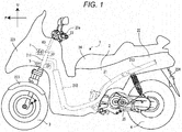
- Fig. 1 is a side view of the whole of the vehicle 1.
- front, rear, left and right are referred to with a view to showing directions, they denote front, rear, left and right as seen from a rider who rides on the vehicle 1.
- the vehicle 1 includes a vehicle main body 2, front wheels 3 and a rear wheel 4.
- the vehicle main body 2 includes a body frame 21, a body cover 22, a handlebar 23, a seat 24 and a power unit 25.
- the body frame 21 supports the power unit 25, the seat 24, and the like.
- the power unit 25 includes an engine, a transmission, and the like.
- Fig. 1 the body frame 21 is shown by broken lines.
- the body frame 21 includes a headpipe 211, a down frame 212, and a rear frame 213.
- the headpipe 211 is disposed in a front portion of the vehicle.
- a link mechanism 5 is disposed on the periphery of the headpipe 211.
- a steering shaft 60 is inserted into the headpipe 211 so as to turn therein.
- the steering shaft 60 extends substantially in an up-and-down direction (the direction of a middle steering axis).
- the handlebar 23 is provided at an upper end portion of the steering shaft 60.
- the down frame 212 is inclined downward from a front end thereof to the rear.
- the rear frame 213 supports the seat 24, a tail lamp, and the like.
- a switch 23a is mounted on the handle 23.
- the body frame 21 is covered with the body cover 22.
- the body cover 22 includes a front cover 221, front fenders 223 and a rear fender 224.
- the front cover 221 is situated ahead of the seat 24.
- the front cover 221 covers the headpipe 211 and the link mechanism 5.
- the front fenders 223 are disposed individually directly above a pair of left and right front wheels 3.
- the front fenders 223 are disposed directly below the front cover 221.
- the rear fender 224 is disposed directly above the rear wheel 4.
- the front wheels 3 are situated below the headpipe 211 and the link mechanism 5.
- the front wheels 3 are disposed directly below the front cover 221.
- the rear wheel 4 is disposed directly below the body cover 22.
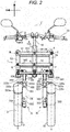
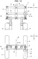
- Fig. 2 is an overall front view of the vehicle 1 with the body cover 22 removed. In Fig. 2 , the down frame 212 is omitted.
- the vehicle 1 includes the handlebar 23, the steering shaft 60, the headpipe 211, the pair of left and right front wheels 3, a first shock absorbing device 33, a first turn preventing mechanism 340, a second shock absorbing device 35, a second turn preventing mechanism 360, the link mechanism 5, an operation force transfer mechanism 6, and a resisting force change mechanism 7.
- the front wheels 3 include a first front wheel 31 and a second front wheel 32 that are disposed side by side in a left-and-right direction of the body frame 21.
- the first front wheel 31, which is an example of a right front wheel, is disposed rightside in relation to a center of the vehicle width direction.
- a first front fender 223a is disposed directly above the first front wheel 31.
- the second front wheel 32 which is an example of a left front wheel, is disposed leftside in relation to the center of the vehicle width direction.
- a second front fender 223b is disposed directly above the second front wheel 32.
- the second front wheel 32 is disposed so as to be symmetrical with the first front wheel 31 in relation to the left-and-right direction of the body frame 21.
- the "left-and-right direction of the body frame 21" denotes a direction which is perpendicular to the direction of an axis of the headpipe 211 when the vehicle 1 is seen from the front thereof.
- the first shock absorbing device 33 which is an example of a right shock absorbing device, supports the first front wheel 31 at a lower portion thereof and absorbs a displacement of the first front wheel 31 in an up-and-down direction of the body frame 21 in relation to an upper portion thereof.
- the first shock absorbing device 33 includes a first shock absorber 330 and a first turn preventing mechanism 340.
- the "up-and-down direction of the body frame 21" denotes a direction that follows the direction of the axis of the headpipe 211 when the vehicle 1 is seen from the front thereof.
- the second shock absorbing device 35 which is an example of a left shock absorbing device, supports the second front wheel 32 at a lower portion thereof and absorbs a displacement of the second front wheel 32 in the up-and-down direction of the body frame 21 in relation to an upper portion thereof.
- the second shock absorbing device 35 includes a second shock absorber 350 and a second turn preventing mechanism 360.
- Fig. 3 is a left side view showing a relationship between the second front wheel 32 and the second shock absorbing device 35.
- the second shock absorber 350 includes a second support member 321.
- the second support member 321 includes a second outer tube 322, a second support shaft 323, and a second inner tube 326. Part of the second inner tube 326 is inserted in an inner circumferential side of the second outer tube 322.
- the second inner tube 326 is disposed directly above the second outer tube 322.
- the second inner tube 326 is movable relative to the second outer tube 322 in a direction in which the second outer tube 322 extends.
- the second shock absorber 350 is a so-called telescopic shock absorber.
- the second turn preventing mechanism 360 prevents the turn of the second outer tube 322 in relation to the second inner tube 326.
- the second turn preventing mechanism 360 includes a second guide 325, a second turn preventing rod 361, and a second bracket 327.
- the second guide 325 guides the moving direction of the second turn preventing rod 361.
- the second guide 325 includes a second guide tube 325b.
- the second turn preventing rod 361 is inserted into an inner circumferential side of the second guide tube 325b.
- the second turn prevention rod 361 can move relative to the second guide tube 325b.
- the second turn preventing rod 361 prevents the relative turn of the second front wheel 32 to the second inner tube 326.
- the second turn preventing rod 361 is disposed parallel to the second shock absorber 350.
- An upper end of the second turn preventing rod 361 and an upper end of the second inner tube 326 are fixed to the second bracket 327. This configuration prevents the relative turn of the second turn preventing rod 361 to the second inner
- the second front wheel 32 is supported by the second support member 321.
- the second front wheel 32 is connected to a lower portion of the second support member 321.
- the second support shaft 323 is provided at a lower end of the second outer tube 322 and supports the second front wheel 32.
- the second guide 325 includes a second plate 325a.
- the second plate 325a extends to upside of the second front fender 223b.
- the second front wheel 32 can turn about a second center axis Y to change its orientation.
- the second center axis Y intersects the second plate 325a at a second connection point 325c.
- the first shock absorber 330 includes a first support member 331.
- the first support member 331 includes a first outer tube 332, a first support shaft 334, and a first inner tube 336.
- the first shock absorber 330 has a similar configuration to that of the second shock absorber 350 that is described by reference to Fig. 3 . Namely, part of the first inner tube 336 is inserted in an inner circumferential side of the first outer tube 332.
- the first inner tube 336 is disposed directly above the first outer tube 332.
- the first inner tube 336 can move relative to the first outer tube 332 in a direction in which the first outer tube 332 extends.
- the first shock absorber 330 is a so-called telescopic shock absorber.
- the first turn preventing mechanism 340 prevents the turn of the first outer tube 332 in relation to the first inner tube 336.
- the first turn preventing mechanism 340 has a similar configuration to that of the second turn preventing mechanism 360 that is described by reference to Fig. 3 .
- the first turn preventing mechanism 34 includes a first guide 333, a first turn preventing rod 341, and a first bracket 335.
- the first guide 333 guides the moving direction of the first turn preventing rod 341.
- the first guide 333 includes a first guide tube 333b.
- a first turn preventing rod 341 is inserted into an inner circumferential side of the first guide tube 333b. The first turn preventing rod 341 can move relative to the first guide tube 333b.
- the first turn prevention rod 341 prevents the relative turn of the first front wheel 31 in relation to the first inner tube 336.
- the first turn preventing rod 341 is disposed parallel to the first shock absorber 330. Upper ends of the first turn preventing rod 341 and the first inner tube 336 are fixed to the first bracket 335. This configuration prevents the relative turn of the first turn preventing rod 341 to the first inner tube 336.
- the first front wheel 31 is supported on the first support member 331.
- the first front wheel 31 is connected to a lower portion of the first support member 331.
- the first support shaft 334 is provided at a lower end of the first outer tube 332 and supports the first front wheel 31.
- the first guide 333 includes a first plate 333a.
- the first plate 333a extends to upside of the first front fender 223a.
- the first front wheel 31 can turn about a first center axis X to change its orientation.
- the first center axis X intersects the first plate 333a at a first connection point 333c.
- the link mechanism 5 is disposed below the handlebar 23.
- the link mechanism 5 is disposed above the first front wheel 31 and the second front wheel 32.
- the link mechanism 5 is connected to the headpipe 211.
- the link mechanism 5 includes a first cross member 51 (an example of an upper cross member), a second cross member 52 (an example of a lower cross member), a first side member 53 (an example of a right side member), and a second side member 54 (an example of a left side member).
- the first cross member 51 includes a pair of plate-shaped members 512.
- the first cross member 51 extends in the left-and-right direction of the body frame 21.
- the pair of plate-shaped members 512 sandwiches the headpipe 211 therebetween in the front-and-rear direction of the body frame 21.
- the "front-and-rear direction of the body frame 21" denotes a direction which coincides with a front-and-rear direction of the vehicle 1.
- a middle portion of the first cross member 51 is supported on the body frame 21 (the headpipe 211) by a support portion A.
- the middle portion of the first cross member 51 is supported on the body frame 21 at the support portion A so as to turn about an upper middle axis AA that extends in the front-and-rear direction of the body frame 21.
- the steering shaft 60 turns as the handlebar 23 is turned, the first cross member 51 does not turn about a turning axis of the steering shaft 60.
- a right end portion of the first cross member 51 is connected to an upper portion of the first side member 53 by a connecting portion B.
- An upper portion of the first side member 53 is supported so as to turn about an upper right axis that extends in the front-and-rear direction of the body frame 21 at the connecting portion B by the right end portion of the first cross member 51.
- a left end portion of the first cross member 51 is connected to an upper portion of the second side member 54 by a connecting portion C.
- An upper portion of the second side member 54 is supported so as to turn about an upper left axis that extends in the front-and-rear direction of the body frame 21 at the connecting portion C by the left end portion of the first cross member 51.
- the upper middle axis AA, upper right axis and upper left axis are parallel to each other.
- the second cross member 52 includes a pair of plate-shaped members 522.
- the second cross member 52 extends in the left-and-right direction of the body frame 21.
- the pair of plate-shaped members 522 sandwiches the headpipe 211 therebetween in the front-and-rear direction of the body frame 21.
- the second cross member 52 is disposed below the first cross member 51 and above the first shock absorbing device 33 and the second shock absorbing device 35.
- a middle portion of the second cross member 52 is supported on the body frame 21 (the headpipe 211) by a support portion D.
- the middle portion of the second cross member 52 is supported on the body frame 21 at the support portion D so as to turn about a lower middle axis that extends in the front-and-rear direction of the body frame 21.
- a turning axis that extends in the front-and-rear direction of the body frame 21 at the support portion D is parallel to a turning axis that extends in the front-and-rear direction of the body frame 21 at the support portion A.
- a right end portion of the second cross member 52 is connected to a lower portion of the first side member 53 by a connecting portion E.
- the lower portion of the first side member 53 is supported so as to turn about a lower right axis that extends in the front-and-rear direction of the body frame 21 at the connecting portion E by the right end portion of the second cross member 52.
- a left end portion of the second cross member 52 is connected to a lower portion of the second side member 54 at a connecting portion F.
- the lower portion of the second side member 54 is supported so as to turn about a lower left axis that extends in the front-and-rear direction of the body frame 21 at the connecting portion F by the left end portion of the second cross member 52.
- the upper middle axis AA, upper right axis, upper left axis, lower middle axis, lower right axis and lower left axis are parallel to each other.
- first cross member 51 and the second cross member 52 each include the pair of front and rear plate-shaped members that extend in the left-and-right direction.
- first cross member 51 and the second cross member 52 may each include a member that extends rightward from the headpipe 211 and a member that extends leftward from the headpipe 211.
- the first side member 53 is disposed directly on the right of the headpipe 211.
- the first side member 53 extends in a direction that is substantially parallel to a direction in which the headpipe 211 and the steering shaft 60 extend.
- the first side member 53 is disposed directly above the first front wheel 31 and the first shock absorbing device 33.
- the first side member 53 supports an upper portion of the first shock absorbing device 33 so as to turn about a first center axis X (an example of a right axis).
- the second side member 54 is disposed directly on the left of the headpipe 211.
- the second side member 54 extends in a direction that is substantially parallel to the direction in which the headpipe 211 and the steering shaft 60 extend.
- the second side member 54 is disposed directly above the second front wheel 32 and the second shock absorbing device 35.
- the second side member 54 supports an upper portion of the second shock absorbing device 35 so as to turn about a second center axis Y (an example of a left axis).
- the steering shaft 60 is supported on the body frame 21 between the first side member 53 and the second side member 54 in the left-and-right direction of the body frame 21.
- An upper end portion of the steering shaft 60 is provided above the turning axis at the support portion D of the second cross member 52 in the up-and-down direction of the body frame 21.
- the steering shaft 60 can turn about a middle steering axis Z that extends in the up-and-down direction of the body frame 21 (the headpipe 211).
- Fig. 5 is a front view showing a state in which the body frame 21 leans leftward by an angle T.
- An upward direction of the body frame 21 is indicated by an arrow UF.
- the upward direction UF of the body frame 21 coincides with a vertically upward direction U.
- the upward direction UF of the body frame 21 does not coincide with the vertically upward direction U.
- the link mechanism 5 When the body frame 21 leans leftward or rightward, the link mechanism 5 is deformed.
- the body frame 21 (the headpipe 211) leans leftward from the upright state thereof.
- the first cross member 51 and the second cross member 52 turn in relation to the headpipe 211, the first side member 53 and the second side member 54.
- the direction in which the first cross member 51 extends and the direction in which the second cross member 52 extends are substantially parallel when the vehicle 1 is seen from the front.
- the left end portion of the first cross member 51 moves further leftwards than the left end portion of the second cross member 52.
- the second side member 54 This causes the second side member 54 to lean leftward from the upright state.
- the direction in which the second side member 54 extends is parallel to the direction in which the headpipe 211 extends when the vehicle is seen from the front thereof.
- the first side member 53 also leans leftward from the upright state.
- the direction in which the first side member 53 extends is parallel to the direction in which the headpipe 211 extends when the vehicle 1 is seen from the front thereof.
- the link mechanism 5 is deformed as described above, the second front wheel 32 is displaced further upwards (to the upward direction UF) of the body frame 21 than the first front wheel 31, whereby the vehicle 1 is permitted to lean leftward.
- the body frame 21 (the headpipe 211) leans rightward from the upright state.
- the first cross member 51 and the second cross member 52 turn in relation to the headpipe 211, the first side member 53 and the second side member 54.
- the direction in which the first cross member 51 extends and the direction in which the second cross member 52 extends are substantially parallel when the vehicle 1 is seen from the front.
- the left end portion of the first cross member 51 moves further rightwards than the left end portion of the second cross member 52. This causes the second side member 54 to lean rightward from the upright state.
- the direction in which the second side member 54 extends is parallel to the direction in which the headpipe 211 extends when the vehicle is seen from the front thereof.
- the first side member 53 also leans rightward from the upright state.
- the direction in which the first side member 53 extends is parallel to the direction in which the headpipe 211 extends when the vehicle 1 is seen from the front thereof.
- the link mechanism 5 is deformed as described above, the first front wheel 31 is displaced further upwards of the body frame 21 than the second front wheel 32, whereby the vehicle 1 is permitted to lean rightward.
- the operation force transfer mechanism 6 which is an example of a turn transfer mechanism, transfers a turn of the steering shaft 60 according to an operation of the handlebar 23 to the first shock absorbing device 33 and the second shock absorbing device 35 so as to turn the first shock absorbing device 33 and the second shock absorbing device 35 about the first center axis X and the second center axis Y, respectively.
- Part of the operation force transfer mechanism 6 is disposed directly below the second cross member 52.
- the operation force transfer mechanism 6 is disposed above the first front wheel 31 and the second front wheel 32.
- a lower end portion of the first side member 53 is connected to the first bracket 335.
- the first bracket 335 is attached to the first side member 53 so as to turn about the first center axis X.
- the operation force transfer mechanism 6 connects the lower end portion of the steering shaft 60 and the first bracket 335 together.
- the operation force transfer mechanism 6 transfers a turn of the steering shaft 60 which is triggered by a turn of the handlebar 23 to the first bracket 335. This causes the first bracket 335 to turn about the first center axis X in relation of the first side member 53.
- the first side member 53 does not turn in relation to the body frame 21, even though the handlebar 23 is turned.
- a lower end portion of the second side member 54 is connected to the second bracket 327.
- the second bracket 327 is attached to the second side member 54 so as to turn about the second center axis Y in relation to the second side member 54.
- the operation force transfer mechanism 6 connects the lower end portion of the steering shaft 60 and the second bracket 327.
- the operation force transfer mechanism 6 transfers a turn of the steering shaft 60 which is triggered by a turn of the handlebar 23 to the second bracket 327. This causes the second bracket 327 to turn about the second center axis Y in relation to the second side member 54.
- the second side member 54 does not turn in relation to the body frame 21, even though the handlebar 23 is turned.
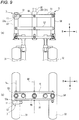
- FIG. 6 is a front view showing the operation force transfer mechanism 6 in an enlarged fashion.
- the operation force transfer mechanism 6 includes the steering shaft 60, a first transfer plate 61, a second transfer plate 62, a third transfer plate 63, a first transfer member 67, the first bracket 335, and the second bracket 327.
- the first transfer plate 61 is connected to the lower end portion of the steering shaft 60.
- the first transfer plate 61 cannot turn in relation to the steering shaft 60.
- the handlebar 23 is turned in relation to the headpipe 211
- the steering shaft 60 turns in relation to the headpipe 211.
- the first transfer plate 61 turns as the steering shaft 60 turns.
- the second transfer plate 62 is fixed to the first bracket 335 of the first shock absorbing device 33 and is allowed to turn together with the first bracket 335 in relation to the first side member 53.
- the second transfer plate 62 is situated below the first bracket 335.
- the third transfer plate 63 is disposed symmetrical with the second transfer plate 62 with respect to the first transfer plate 61.
- the third transfer plate 63 is fixed to the second bracket 327 of the second shock absorbing device 35 and is allowed to turn together with the second bracket 327 in relation to the second side member 54.
- the third transfer plate 63 is situated below the second bracket 327.
- a portion which is fixed to the first shock absorbing device 33 and which can turn together with the first shock absorbing device 33 is understood to constitute part of the first shock absorbing device 33. Consequently, the second transfer plate 62 of the operation force transfer mechanism 6 also constitutes part of the first shock absorbing device 33. Similarly, a portion which is fixed to the second shock absorbing device 35 and which can turn together with the second shock absorbing device 35 is understood to constitute part of the second shock absorbing device 35. Consequently, the third transfer plate 63 of the operation force transfer mechanism 6 also constitutes part of the second shock absorbing device 35.
- the first transfer member 67 transfers an operation force that is transferred from the steering shaft 60 to the first bracket 335 and the second bracket 327.
- the first transfer member 67 extends in the left-and-right direction of the body frame 21. A configuration for enabling the operation force to be transferred from the steering shaft 60 to the first bracket 335 and the second bracket 327 will be described in detail later.
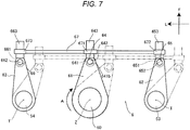
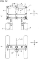
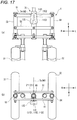
- FIG. 7 is a schematic plan view showing the configuration of the operation force transfer mechanism 6.
- the operation force transfer mechanism 6 is viewed from thereabove with the configurations of the link mechanism 5, the brackets and the like all omitted.
- Two-dot chain lines in FIG. 7 indicate a state in which the steering shaft 60 is turned in a direction indicated by an arrow A.
- the operation force transfer mechanism 6 includes a first joint 64, a second joint 65, and a third joint 66.
- the first transfer plate 61 is narrowed in width more at a front portion than at a rear portion of the first transfer plate 61.
- the first joint 64 is disposed at the front portion of the first transfer plate 61.
- the second transfer plate 62 is narrowed in width more at a front portion than at a rear portion of the second transfer plate 62.
- the second joint 65 is disposed directly ahead of the second transfer plate 62.
- the second transfer plate 62 is disposed directly on the right of the first transfer plate 61.
- the third transfer plate 63 is narrowed in width more at a front portion than at a rear portion of the third transfer plate 63.
- the third joint 66 is disposed directly ahead of the third transfer plate 63.
- the third transfer plate 63 is disposed directly on the left of the first transfer plate 61.
- the first joint 64 includes a first bearing 641, a first shaft 642 and a first front rod 643.
- the first shaft 642 can turn relative to the first bearing 641.
- the first bearing 641 supports the first shaft 642.
- the first bearing 641 is supported on the first transfer plate 61.
- the first transfer plate 61 includes a first support hole 641b that supports the first shaft 642.
- the first shaft 642 is fitted in the first support hole 641b.
- the first bearing 641 is fixed to the first shaft 642.
- the first shaft 642 is disposed at a front end of the first transfer plate 61.
- the first front rod 643 extends forward from the first bearing 641.
- the first front rod 643 can turn relatively leftward or rightward about the first shaft 642 as a result of the first bearing 641 turning in relation to the first transfer plate 61.
- the first front rod 643 is fixed to the first bearing 641.
- the second joint 65 includes a second bearing 651, a second shaft 652 and a second front rod 653.
- the second bearing 651 has a configuration similar to that of the first bearing 641.
- the second shaft 652 has a configuration similar to that of the first shaft 642.
- the second front rod 653 has a configuration similar to that of the first front rod 643.
- the third joint 66 includes a third bearing 661, a third shaft 662 and a third front rod 663.
- the third bearing 661 has a configuration similar to that of the first bearing 641.
- the third shaft 662 has a configuration similar to that of the first shaft 642.
- the third front rod 663 has a configuration similar to that of the first front rod 643.
- the first transfer member 67 includes a first ring 671, a second ring 672 and a third ring 673.
- the first front rod 643 is inserted through the first ring 671.
- the first ring 671 is provided at a center in a left-and-right direction of the first transfer member 67.
- the second ring 672 is disposed directly on the right of the first ring 671.
- the second front rod 653 is inserted into the second ring 672.
- the third ring 673 is disposed directly on the left of the first ring 671.
- the third front rod 663 is inserted into the third ring 673.
- FIG. 8 is a plan view showing the second front wheel 32 and the second bracket 327. Two-dot chain lines in FIG. 8 indicate a state in which the second front wheel 32 is turned. The second front fender 223b is omitted from the illustration.
- the second bracket 327 is connected to the second side member 54 as has been described above.
- the third transfer plate 63 is mounted on the second bracket 327.
- the first transfer plate 61 turns as the steering shaft 60 turns.
- the first joint 64 moves rightward and rearward as the first transfer plate 61 turns.
- the first shaft 642 rotates in relation to the first bearing 641 to thereby move the first transfer member 67 rightward and rearward while maintaining the posture of the first transfer member 67.
- the second front rod 653 and the third front rod 663 move rightward and rearward as the first transfer member 67 moves rightward.
- the second bearing 651 and the third bearing 661 move rightward and rearward.
- the second transfer plate 62 and the third transfer plate 63 turn in the direction indicated by the arrow A about the first side member 53 and the second side member 54, respectively. This creates the state indicated by the two-dot chain lines in FIG. 7 .
- a turning center of the second transfer plate 62 coincides with the first center axis X.
- a turning center of the third transfer plate 63 coincides with the second center axis Y.
- the second bracket 327 turns in a direction indicated by an arrow B in Fig. 8 via a third transfer member 69.
- the second front wheel 32 turns in a direction indicated by an arrow C in Fig. 8 via the second shock absorber 350.
- the front wheel 32 turns rightward about the second center axis Y. As this occurs, the front wheel 32 takes a position indicated by two-dot chain lines in FIG. 8 .
- the first front wheel 31 turns rightward about the first center axis X. In this way, the first front wheel 31 and the second front wheel 32 turn in the left-and-right direction of the body frame 21 by turning the handlebar 23 in the left-and-right direction of the body frame 21.
- the resisting force change mechanism 7 suppresses a deformation of the link mechanism 5. Specifically, the resisting force change mechanism 7 can change resisting force being exerted against a relative turning between the first cross member 51 and the second cross member 52 with respect to the body frame 21. The resisting force change mechanism 7 can change the resisting force, which occurs when the upper cross member 51 and the lower cross member 52 are displaced from their respective positions relative to the body frame 21, in at least two different magnitudes.
- Fig. 9 is a view describing the resisting force change mechanism 7.
- the vehicle body cover 22 and the like are not illustrated in Fig. 9.
- Fig. 9a is a front view illustrating a part of the vehicle 1 equipped with the resisting force change mechanism 7.
- Fig. 9a is a view of a part of the vehicle 1 when seen from the front in a direction of the upper middle axis AA.
- Fig. 9b is a view when the body frame 21 illustrated in Fig. 9a is seen from above.
- the resisting force change mechanism 7 of the embodiment is a so-called drum brake.
- the drum brake is disclosed in Japanese Patent Unexamined Publication JP-A-2000-329168 and the like.
- the resisting force change mechanism 7 includes an inner element 11 and a cylindrical drum 12.
- the inner element 11 is disposed inside of the cylindrical drum 12.
- the inner element 11 turns relative to the drum 12 about a resisting force change axis 7a which is parallel with the upper middle axis AA.
- the resisting force change axis 7a coincides with the upper right axis.
- the inner element 11 is fixed to the right side member 53.
- the drum 12 is fixed to the upper cross member 51.
- the drum 12 has an inner circumferential surface 12a that extends in parallel with the resisting force change mechanism 7 (refer to Fig. 10 ).
- the inner circumferential surface 12a of the drum 12 has a circular shape when seen in the direction of the upper middle axis AA.
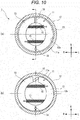
- Fig. 10 is a schematic view of an internal structure of the resisting force change mechanism 7 when seen from the front in the direction of the upper middle axis AA.
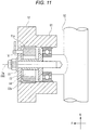
- Fig. 11 is a vertical cross-sectional view of the resisting force change mechanism 7.
- the inner element 11 includes a pair of brake shoes 13.
- the brake shoe 13 has a semicircular shape when seen in the direction of the upper middle axis AA.
- the brake shoe 13 has an outer circumferential surface 11a that extends in parallel with the resisting force change axis 7a.
- the outer circumferential surface 11a of the brake shoe 13 has approximately the same curvature as that of the inner circumferential surface 12a of the drum 12.
- a connection shaft 14 is provided between respective lower portions of the pair of brake shoes 13.
- the respective lower portions of the pair of brake shoes 13 are turnably connected to the connection shaft 14.
- the connection shaft 14 extends in parallel with the upper middle axis AA.
- the pair of brake shoes 13 are turnably supported by the connection shaft 14.
- the connection shaft 14 is fixed to an upper right axial portion 53a of the right side member 53.
- the upper right axial portion 53a extends forward from the right side member 53 so as to be parallel with the upper right axis.
- the upper right axial portion 53a passes through the upper cross member 51, and protrudes forward of the upper cross member 51.
- Springs 15 are respectively connected to the pair of brake shoes 13.
- the spring 15 always exerts a force on the brake shoe 13, and the force is exerted in a direction in which the outer circumferential surface 11a of the brake shoe 13 separates from the inner circumferential surface 12a of the drum.
- a cam 16 is provided between respective upper portions of the pair of brake shoes 13.
- the cam 16 is an elliptical shape when seen in the direction of the upper middle axis AA.
- the cam 16 can turn about a cam axis in parallel with the upper middle axis AA.
- a driver can turn the cam 16 by operating an operation unit provided on the handlebar 23.
- the operation unit can be a switch, a button, a lever, or the like.
- the cam 16 When the cam 16 turns about the cam axis, the cam 16 widens a gap between the respective upper portions of the pair of brake shoes 13.
- the outer circumferential surface 11a of the brake shoe 13 comes into contact with the inner circumferential surface 12a of the drum 12, and a frictional force occurs between the outer circumferential surface 11a of the brake shoe 13 and the inner circumferential surface 12a of the drum 12. Accordingly, the resisting force change mechanism 7 changes the resisting force against a relative displacement between the inner element 11 and the drum 12.
- the upper cross member 51 and the lower cross member 52 turn with respect to the body frame 21. Accordingly, the right side member 53 turns with respect the upper cross member 51 about the upper right axis.
- the inner member 11 is a first portion of the resisting force change mechanism 7, and is fixed to the right side member 53 which is one member of the link mechanism 5.
- the drum 12 is a second portion of the resisting force change mechanism 7, and is fixed to the upper cross member 51 which is the other member of the link mechanism 5. For this reason, the drum 12 turns with respect to the inner element 11 about the resisting force change axis 7a in synchronization with the turning of the right side member 53 relative to the upper cross member 51.
- the resisting force change mechanism 7 of the embodiment can change a resisting force being exerted against a turning operation of each the upper cross member 51 and the lower cross member 52 with respect to the body frame 21.
- the resisting force change mechanism 7 can change a resisting force, which occurs when the upper cross member 51 and the lower cross member 52 are displaced from their respective positions relative to the body frame 21, in at least two different magnitudes.
- the resisting force which occurs when the upper cross member 51 and the lower cross member 52 are displaced from their respective positions relative to the body frame 21 can be changed in at least two different magnitudes means that respective resisting forces on the upper cross member 51 and the lower cross member 52 with respect to the body frame 21 in an upright state can be changed.
- the resisting force change mechanism 7 has the first portion (the inner element 11) and the second portion (the drum 12) that can turn relative to each other about the resisting force change axis 7a which is parallel with the upper middle axis AA, and that can change a resisting force against the relative turning.
- the inner element 11 is non-turnably fixed to one member (the right side member 53 in the embodiment) of the right side member 53, a left side member 54, the upper cross member 51, the lower cross member 52 and the body frame 21.
- the drum 12 is supported by the other member (the upper cross member 51 in the embodiment) of the right side member 53, the left side member 54, the upper cross member 51, the lower cross member 52 and the body frame 21, at least a part of which is turnably supported by one member.
- the drum 12 turns with respect to the inner element 11 about the resisting force change axis 7a in synchronization with the turning of one member (the upper cross member 51) relative to the other member (the upper cross member 51).
- the drum 12 turns relative to the inner element 11 about the resisting force change axis 7a which is parallel with the upper middle axis AA.
- the resisting force change mechanism 7 changes a resisting force which occurs when the inner element 11 and the drum 12 turn relative to each other about the resisting force change axis 7a which is parallel with the upper middle axis AA. Since the inner element 11 and the drum 12 turn about the resisting force change axis 7a, the resisting force change mechanism 7 is unlikely to increase in size seen in the direction of the upper middle axis AA.
- the inner element 11 is fixed to one member (the right side member 53) of the link mechanism 5.
- the other member (the upper cross member 51) of the link mechanism 5 supports the drum 12, and is turnably supported by one member (the right side member 53). Since the right side member 53 and the upper cross member 51 turn about the upper right axis, the right side member 53 and the upper cross member 51 are disposed close to each other when seen from the front in the direction of the upper middle axis AA.
- the inner element 11 is fixed to the right side member 53 and the drum 12 is fixed to the upper cross member 51. It is possible to dispose the inner element 11 and the drum 12 close to each other, and it is possible to make the resisting force change mechanism 7 compact when seen from the front in the direction of the upper middle axis AA.
- the right side member 53 and the upper cross member 51 of the link mechanism 5 turn relative to each other about the upper right axis which is parallel with the upper middle axis AA.
- the inner element 11 and the drum 12 of the resisting force change mechanism 7 turn relative to each other about the upper right axis which is parallel with the upper middle axis AA. Since a movement direction of the members of the link mechanism 5 is parallel with a movement direction of the members of the resisting force change mechanism 7, the resisting force change mechanism 7 is prevented from interfering with the link mechanism 5. For this reason, it is possible to prevent interference between the resisting force change mechanism 7 and the link mechanism 5, and it is possible to suppress an increase in size of the vehicle 1 even when equipped with the resisting force change mechanism 7.
- the inner element 11 is fixed to one configuration member (the right side member 53) of the link mechanism 5.
- the drum 12 is supported by the other configuration member (the upper cross member 51) of the link mechanism 5.
- the inner element 11 turns relative to the drum 12, in synchronization with the relative turning between one configuration member and the other configuration member of the link mechanism 5.
- the link mechanism 5 is obtained by assembling together the members such as the right side member 53 and the upper cross member 51 which turn relative to each other. Since the inner element 11 and the drum 12 of the resisting force change mechanism 7 are respectively provided on the members of the link mechanism 5, the inner element 11 and the drum 12 of the resisting force change mechanism turn relative to each other, in synchronization with a turning operation of the link mechanism 5. As such, the resisting force change mechanism 7 changes a resisting force against the relative turning between the inner element 11 and the drum 12 by using the turning operation of the link mechanism 5. For this reason, it is possible to simplify the structure of the resisting force change mechanism 7, and it is possible to make the resisting force change mechanism 7 compact.
- the embodiment it is possible to configure the vehicle 1 with the compact resisting force change mechanism 7. Even when the vehicle 1 is equipped with the resisting force change mechanism 7, a structure on the circumference of the steering shaft 60 is prevented from increasing in size.
- the resisting force change axis 7a coincides with the upper right axis which is a turning axis of the right side member 53 and the upper cross member 51. For this reason, it is possible to make the resisting force change mechanism 7 compact when seen from the front in the direction of the upper middle axis AA.
- the right side member 53 is provided with the upper right axial portion 53a by which the upper cross member 51 is supported so as to be turnable about the upper right axis which is parallel with the upper middle axis AA.
- the inner element 11 is fixed to the upper right axial portion 53a.
- the upper right axial portion 53a of the right side member 53 has a function of turnably supporting the upper cross member 51, and a function of supporting the inner element 11 of the resisting force change mechanism 7. For this reason, it is possible to make the link mechanism 5 and the resisting force change mechanism 7 compact.
- the outer circumferential surface 11a of the brake shoe 13 of the inner element 11 extends in a direction of the resisting force change axis 7a.
- the inner circumferential surface 12a of the drum 12 faces the outer circumferential surface 11a of the brake shoe 13, and extends in the direction of the resisting force change axis 7a.
- the resisting force change mechanism 7 can change a frictional force (a resisting force against the relative turning between the inner element 11 and the drum 12) between the outer circumferential surface 11a of the brake shoe 13 and the inner circumferential surface 12a of the drum 12.
- the resisting force change mechanism 7 can generate a large resisting force even when the size thereof seen in the direction of the upper middle axis AA remains unchanged.
- each of the outer circumferential surface 11a of the brake shoe 13 and the inner circumferential surface 12a of the drum 12 has an arc shape when seen in the direction of the upper middle axis AA.
- the outer circumferential surface 11a of the drum 12 is easily formed into an arc shape, forming an external appearance of the deformation force suppressing mechanism 7, and it is possible to prevent the deformation force suppressing mechanism 7 from interfering with vehicle mounting components such as a lamp which is disposed on the circumference thereof.
- the resisting force change mechanism 7 has a so-called drum brake mechanism. For this reason, a self-servo action occurs in the resisting force change mechanism 7, and the turning of the upper cross member 51 and the lower cross member 52 relative to the body frame 21 is likely to stop.
- the upper cross member 51 turns with respect to the right side member 53 in a clockwise direction when seen from the front in the direction of the upper middle axis AA
- the drum 12 turns with respect to the inner element 11 in the clockwise direction when seen from the front in the direction of the upper middle axis AA.
- the inner circumferential surface 12a of the drum 12 exerts a force on the left brake shoe 13, and the force causes the brake shoe 13 to turn with the clockwise turning of the drum 12. Since the lower portion of the left brake shoe 13 is connected to the connection shaft 14, the upper portion of the left brake shoe 13 leans toward the inner circumferential surface 12a of the drum 12, and the right brake shoe 13 is more strongly pressed against the inner circumferential surface 12a of the drum 12. Accordingly, a frictional force between the right brake shoe 13 and the drum 12 increases. When the drum 12 turns with respect to the inner element 11 in a counter-clockwise direction, a resisting force to stop the counter-clockwise turning increases.
- the resisting force change mechanism 7 Since the resisting force change mechanism 7 generates a large resisting force, it is easy to reduce the size of the resisting force change mechanism 7.
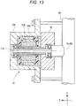
- FIG. 12 is a view illustrating the resisting force change mechanism 7A according to the embodiment, and corresponding to Fig. 9 .
- Fig. 12a is a view of the resisting force change mechanism 7A when seen from the front in the direction of the upper middle axis AA.
- Fig. 12b is a view of the resisting force change mechanism 7A illustrated in Fig. 12a when seen from the top of the body frame 21.
- Fig. 13 is a vertical cross-sectional view of the resisting force change mechanism 7A.
- the resisting force change mechanism 7A of the embodiment is a so-called magnetic fluid brake mechanism.
- the magnetic fluid brake mechanism is disclosed in Japanese Patent Unexamined Publication JP-A-2010-167999 and the like.
- the resisting force change mechanism 7A includes an outer cylinder 12A (an example of the second portion); a center shaft portion 11A (an example of the first portion) that is turnably provided inside of the outer cylinder 12A; magnetic fluid which is filled in a fluid chamber 13A provided between the outer cylinder 12A and the center shaft portion 11A; and a coil 14A.
- the magnetic fluid which is filled in the fluid chamber 13A is a fluid of which viscosity properties change due to magnetic field.
- the outer cylinder 12A and the center shaft portion 11A can turn relative to each other about the resisting force change axis 7a which is parallel with an upper central axis.
- the resisting force change axis 7a coincides with the lower left axis which is the center of relative turning between the left side member 54 and the lower cross member 52.
- the resisting force change mechanism 7A can change the viscosity of the magnetic fluid by applying the magnetic field with the coil 14A.
- the center shaft portion 11A is fixed to the lower cross member 52.
- the outer cylinder 12A is fixed to the left side member 54. For this reason, the outer cylinder 12A turns with respect to the center shaft portion 11A about the resisting force change axis 7a, in synchronization with the turning of the left side member 54 relative to the lower cross member 52.
- the left side member 54 turns with respect to the lower cross member 52 about the lower left axis.
- the outer cylinder 12A turns with respect to the center shaft portion 11A, in synchronization with the relative turning between the left side member 54 and the lower cross member 52.
- the coil 14A changes the viscosity of the magnetic fluid, a resisting force against the relative turning between the outer cylinder 12A and the center shaft portion 11A is changed. Accordingly, the resisting force change mechanism 7A can change a resisting force against the relative turning between the left side member 54 and the lower cross member 52.
- the outer cylinder 12A turns relative to the center shaft portion 11A about the resisting force change axis 7a which is parallel with the upper middle axis AA.
- the resisting force change mechanism 7A changes the resisting force against the relative turning between the center shaft portion 11A and the outer cylinder 12A about the resisting force change axis 7a which is parallel with the upper middle axis AA. Since the center shaft portion 11A and the outer cylinder 12A turn about the resisting force change axis 7a, the resisting force change mechanism 7A is unlikely to increase in size seen in the direction of the upper middle axis AA.
- the center shaft portion 11A is fixed to one member (the lower cross member 52) of the link mechanism 5.
- the other member (the left side member 54) of the link mechanism 5 supports the outer cylinder 12A, and is turnably supported by one member (the lower cross member 52). Since the left side member 54 and the lower cross member 52 turn about the lower left axis, the left side member 54 and the lower cross member 52 are disposed close to each other when seen from the front in the direction of the upper middle axis AA.
- the center shaft portion 11A is fixed to the lower cross member 52 and the outer cylinder 12A is fixed to the left side member 54. It is possible to dispose the center shaft portion 11A and the outer cylinder 12A close to each other and it is possible to make the resisting force change mechanism 7A compact when seen from the front in the direction of the upper middle axis AA.
- the left side member 54 and the lower cross member 52 of the link mechanism 5 turn relative to each other about the lower left axis which is parallel with the upper middle axis AA.
- the center shaft portion 11A and the outer cylinder 12A of the resisting force change mechanism 7A turn relative to each other about the lower left axis which is parallel with the upper middle axis AA. Since the movement direction of the members of the link mechanism 5 is parallel with the movement direction of the members of the resisting force change mechanism 7A, the resisting force change mechanism 7A is prevented from interfering with the link mechanism 5. For this reason, it is possible to prevent interference between the resisting force change mechanism 7A and the link mechanism 5 and it is possible to suppress an increase in size of the vehicle 1 even when equipped with the resisting force change mechanism 7A.
- center shaft portion 11A is fixed to one configuration member (the lower cross member 52) of the link mechanism 5.
- the outer cylinder 12A is supported by the other configuration member (the left side member 54) of the link mechanism 5.
- the center shaft portion 11A turns relative to the outer cylinder 12A in synchronization with the relative turning between one configuration member and the other configuration member of the link mechanism 5.
- the link mechanism 5 is obtained by assembling members such as the left side member 54 and the lower cross member 52 which turn relative to each other. Since the center shaft portion 11A and the outer cylinder 12A of the resisting force change mechanism 7A are respectively provided on the members of the link mechanism 5, the center shaft portion 11A and the outer cylinder 12A of the resisting force change mechanism 7A turn relative to each other in synchronization with the turning operation of the link mechanism 5. As such, the resisting force change mechanism 7A changes a resisting force against the relative turning between the center shaft portion 11A and the outer cylinder 12A by using the turning operation of the link mechanism 5. For this reason, it is possible to simplify the structure of the resisting force change mechanism 7A and it is possible to make the resisting force change mechanism 7A compact.
- the third embodiment of the present invention will be described with reference to Figs. 14 to 16 . Since only the resisting force change mechanism in the third embodiment is different from that in the first embodiment, the resisting force change mechanism will be mainly described. Each element which is the same as or similar to that of the first embodiment is not illustrated. The same reference number is assigned to the same or similar element, and the description thereof is omitted.
- Fig. 14 is a view illustrating a resisting force change mechanism 7B according to the embodiment and corresponding to Fig. 9 .
- Fig. 14a is a view of the resisting force change mechanism 7B when seen from the front in the direction of the upper middle axis AA.
- Fig. 14b is a view of the resisting force change mechanism 7B illustrated in Fig. 14a when seen from the top of the body frame 21.
- Fig. 15 is a vertical cross-sectional view of the resisting force change mechanism 7B.
- Fig. 16 is a schematic view describing an operational principle of the resisting force change mechanism 7B.
- the resisting force change mechanism 7B of the embodiment is a so-called oil rotary damping mechanism.
- the oil rotary damping mechanism is disclosed in Japanese Patent Unexamined Publication JP-A-2013-510053 and the like.
- the resisting force change mechanism 7B includes a case 12B, and a center shaft portion 11B provided inside of the case 12B.
- the center shaft portion 11B is fixed to the upper cross member 51.
- the case 12B is fixed to the head pipe 211 which is a part of the body frame 21.
- the center shaft portion 11B can turn with respect to the case 12B about the resisting force change axis 7a that coincides with the upper middle axis AA.
- a fluid chamber is provided between the case 12B and the center shaft 11B and is filled with a fluid.
- the fluid chamber is divided into a first fluid chamber 13B and a second fluid chamber 14B by a partition wall 15B that extends from the center shaft 11B.
- the partition wall 15B is in fluid tight contact with the fluid chamber.
- the first fluid chamber 13B and the second fluid chamber 14B are connected to each other via a communication path 16B that is provided in the case 12B.
- the communication path 16B is provided with a first one-way valve 19Ba, a second one-way valve 19Bb, a first normally closed solenoid valve 17B, and a second normally closed solenoid valve 18B.
- the center shaft portion 11B is allowed to turn relative to the case 12B only in the counter-clockwise direction. That is, the upper cross member 51 is allowed to turn with respect to the head pipe 211 only in the counter-clockwise direction when seen from the front.
- the center shaft portion 11B is allowed to turn relative to the case 12B only in the clockwise direction when seen from the front. That is, the upper cross member is allowed to turn with respect to the head pipe 211 only in the clockwise direction.
- both the first solenoid valve 17B and the second solenoid valve 18B are open, the fluid can flow from the first fluid chamber 13B to the second fluid chamber 14B and vice versa.
- the center shaft portion 11B can turn relative to the case 12B in the clockwise and counter-clockwise directions. That is, the upper cross member 51 can turn relative to the head pipe 211 in the clockwise and counter-clockwise directions.
- a driver can adjust the opening degree of each the first solenoid value 17B and the second solenoid valve 18B by operating an operation unit.
- the operation unit can be an operation lever, an operation button, an operation switch, or the like.
- the operation unit can be provided on the handlebar 23.
- the center shaft portion 11B turns relative to the case 12B about the resisting force change axis 7a that coincides with the upper middle axis AA.
- the resisting force change mechanism 7B changes a resisting force against the relative turning between the center shaft portion 11B and the case 12B about the resisting force change axis 7a that coincides with the upper middle axis AA. Since the center shaft portion 11B and the case 12B turn about the resisting force change axis 7a, the resisting force change mechanism 7B is unlikely to increase in size seen in the direction of the upper middle axis AA.
- the center shaft portion 11B is fixed to one member (the upper cross member 51) of the link mechanism 5.
- the case 12B is supported by the other member (the body frame 21) that turnably supports one member (the upper cross member 51) of the link mechanism 5. Since the upper cross member 51 and the head pipe 211 turn about the upper middle axis AA, the upper cross member 51 and the head pipe 211 are disposed close to each other when seen from the front in the direction of the upper middle axis AA.
- the center shaft portion 11B is fixed to the upper cross member 51 and the case 12B is fixed to the head pipe 211. It is possible to dispose the center shaft portion 11B and the case 12B close to each other and it is possible to make the resisting force change mechanism 7B compact when seen from the front in the direction of the upper middle axis AA.
- the upper cross member 51 and the head pipe 211 of the link mechanism 5 turn relative to each other about the upper middle axis AA.
- the center shaft portion 11B and the case 12B of the resisting force change mechanism 7B turn relative to each other about the upper middle axis AA. Since a movement direction of the members of the link mechanism 5 with respect to the head pipe 211 is parallel with a movement direction of the members of the resisting force change mechanism 7B, the resisting force change mechanism 7B is prevented from interfering with the link mechanism 5. For this reason, it is possible to prevent interference between the resisting force change mechanism 7B and the link mechanism 5, and it is possible to suppress an increase in size of the vehicle 1 even when equipped with the resisting force change mechanism 7B.
- center shaft portion 11B is fixed to one configuration member (the upper cross member 51) of the link mechanism 5.
- the case 12B is supported by the head pipe 211.
- the center shaft portion 11B turns relative to the case 12B in synchronization with the relative turning between one configuration member and the other configuration member of the link mechanism 5.
- the link mechanism 5 is obtained by assembling together the members such as the left side member 54 and the lower cross member 52 which turn about the axis being parallel with the body frame 21. Since the center shaft portion 11B and the case 12B of the resisting force change mechanism 7B are respectively provided on the members of the link mechanism 5, the center shaft portion 11B and the case 12B of the resisting force change mechanism turn relative to each other in synchronization with a turning operation of the link mechanism 5. As such, the resisting force change mechanism 7B changes the resisting force against the relative turning between the center shaft portion 11B and the case 12B by using the turning operation of the link mechanism 5. For this reason, it is possible to simplify the structure of the resisting force change mechanism 7B and it is possible to make the resisting force change mechanism 7B compact.
- each of an outer circumferential surface of the center shaft portion 11B and an inner circumferential surface of the case 12B has a circular shape when seen in the direction of the upper middle axis AA.
- the outer circumferential surface of the case 12B is easily formed into an arch shape, forming an external appearance of the deformation force suppressing mechanism 7B, and it is possible to more effectively prevent the deformation force suppressing mechanism 7B from interfering with vehicle mounting components which are disposed on the circumference thereof.
- the resisting force change mechanism 7B is provided to overlap the steering shaft 60 when seen in the direction of the upper middle axis AA. Since the steering shaft 60 is positioned at the center in the width direction of the vehicle 1, the resisting force change mechanism 7B is also positioned at the center in the width direction of the vehicle. For this reason, the resisting force change mechanism 7B is unlikely to protrude out of a movable range of the link mechanism 5 seen in the direction of the upper middle axis AA.
- the resisting force change axis coincides with any one of the six turning axes (the upper right axis, the upper middle axis AA, the upper left axis, the lower right axis, the lower middle axis, and the lower left axis) of the link mechanism.
- the resisting force parallel axis may deviate from the six turning axes of the link mechanism.
- a resisting force change mechanism 7C according to a fourth embodiment of the present invention is a modification example of the third embodiment.
- the resisting force change axis 7a deviates to the right of the lower left axis.
- Fig. 17 is a view illustrating the resisting force change mechanism 7C according to the embodiment and corresponding to Fig. 14 .
- the resisting force change mechanism 7C has a case 12C as an example of the first portion, and an inner element 11C as an example of the second portion.
- the inner element 11C turns relative to the case 12C about the resisting force change axis 7a which is parallel with the upper middle axis AA.
- the case 12C is fixed to the head pipe 211 which is a part of the body frame 21.
- the inner element 11C has a first turning element 11C1, a second turning element 11C2 and a third turning element 11C3.
- Each of the first to third turning elements 11C1 to 11C3 can turn about a turning axis which is parallel with the upper middle axis AA.
- a gear is provided on an outer circumferential surface of each of the first to third turning elements 11C1 to 11C3 and thus a turning operation thereof can be transmitted to each other.
- the first turning element 11C1 is fixed to the upper cross member 51.
- the third turning member 11C3 is turnably supported by the case 12C.
- the third turning member 11C3 can turn about the resisting force turning axis 7a that is parallel with the upper middle axis AA and is positioned below the upper middle axis AA.
- the second turning element 11C2 is turnably supported by the case 12C, and transmits a turning operation of the first turning element 11C1 to the third turning element 11C3.
- one of the drum brake mechanism, a magnetic fluid brake mechanism and the oil rotary damping mechanism is used as the resisting force change mechanism.
- the present invention is not limited to the embodiments. It is possible to adopt any well-known technology as the resisting force change mechanism insofar as it is possible to change a resisting force against a relative turning between the first and second portions by using the technology. For example, it is possible to use a wet multiple disc brake structure as the resisting force change mechanism.
- the resisting force change mechanism may be provided in the vicinity of any one of the six turning axes (the upper right axis, the upper middle axis AA, the upper left axis, the lower right axis, the lower middle axis and the lower left axis) of the link mechanism 5.
- a single resisting force change mechanism is provided in the vehicle, but the present invention is not limited to the embodiments.
- a plurality of the resisting force change mechanisms is provided in the vicinity of any one of the six turning axes (the upper right axis, the upper middle axis AA, the upper left axis, the lower right axis, the lower middle axis and the lower left axis) of the link mechanism 5.
- Fig. 18 is a view describing a position in which the resisting force change mechanism is provided and corresponding to Fig. 9 .
- part of the link mechanism 5 is supported on the headpipe 211.
- a configuration may be adopted in which the down frame 212 supports part of the link mechanism 5.
- the first shock absorbing device 33 and the second shock absorbing device 35 each includes the telescopic shock absorber.
- the first shock absorbing device 33 and the second shock absorbing device 35 may each include a bottom-link type shock absorber.
- the invention can be applied to a scooter-type straddle vehicle, for example, as long as the vehicle includes a body frame that can lean and two front wheels.
- the words such as "right-hand side,” “left-hand side,” “upper side,” “lower side,” and “outer side” that are described in the description of the Japanese Patent Application correspond, respectively, to the words such as “rightward,” “leftward,” “upward,” “downward,” and “outward” in the description of this patent application.
Landscapes
- Engineering & Computer Science (AREA)
- Mechanical Engineering (AREA)
- Chemical & Material Sciences (AREA)
- Combustion & Propulsion (AREA)
- Transportation (AREA)
- Automatic Cycles, And Cycles In General (AREA)
- Steering Devices For Bicycles And Motorcycles (AREA)
Description
- The present invention relates to a vehicle equipped with a leanable body frame and two front wheels.
- A vehicle is known which includes a body frame that leans leftward or rightward while the vehicle is cornering and two front wheels that are provided to be aligned side by side in a left-and-right direction of the body frame (for example, refer to
Patent Documents US 2010/194068 A1 , which is considered as the closest prior art. - The vehicle including the body frame that can lean and the two front wheels includes a link mechanism. The link mechanism includes an upper cross member and a lower cross member. In addition, the link mechanism also includes a right side member which supports right end portions of the upper cross member and the lower cross member and a left side member which supports left end portions of the upper cross member and the lower cross member. The upper cross member and the lower cross member are supported on the body frame at their middle portions ahead of a steering shaft. The upper cross member and the lower cross member are supported on the body frame so as to be turnable about axes extending substantially in a front-and-rear direction of the body frame. The upper cross member and the lower cross member turn relative to the body frame as the body frame leans, whereby the relative positions of the two front wheels in an up-and-down of the body frame change. The upper cross member and the lower cross member are provided upwards of the two front wheels in the up-and-down direction of the body frame in an upright state of the body frame.
- The vehicle including the body frame that can lean and the two front wheels includes a right shock absorbing device which supports the right front wheel so as to move in the up-and-down direction of the body frame and a left shock absorbing device which supports the left front wheel so as to move in the up-and-down direction of the body frame. The right shock absorbing device is supported on the right side member so as to turn about the axis of the right side member. The left shock absorbing device is supported on the left side member so as to turn about the axis of the left side member. Vehicles described in
Patent Documents - The vehicle including the body frame that can lean and the two front wheels include a number of on-board components which are provided on the periphery of the steering shaft. The on-board components include lamps such as a headlamp, a radiator, a reservoir tank, electric components such as a horn, and a main switch of the vehicle, a stowage box, a stowage pocket and the like.
-
- [Patent Document 1] Japanese Patent Unexamined publication
JP-A-2005-313876 - [Patent Document 2] German Patent Application No.
102010052716 - [Patent Document 3] U.S. Design Patent D547, 242S
- [Non-Patent Document 1] Catalogo partidi ricambio, MP3 300 64102 ie LT Mod. ZAPM64102, Piaggio
- The vehicles described in
Patent Document 1 andPatent Document 2 include a resisting force change mechanism. The resisting force change mechanism suppresses the leaning of the body frame and the change in relative position of the two front wheels in the vertical direction of the body frame by increasing a resisting force against the operation of the link mechanism. - In the vehicle described in
Patent Document 1, the resisting force change mechanism includes a brake disc and a caliper. The brake disc is fixed to the upper cross member which makes up the link mechanism. The caliper changes the resisting force that is exerted on the link mechanism in operation by controlling the frictional force between the caliper and the brake disc. The caliper is attached to the body frame in a position which is situated above the upper cross member. The link mechanism operates when the resisting force exerted by the resisting force change mechanism is zero or small. In the case of the resisting force exerted by the resisting force change mechanism being large, the operation of the link mechanism is suppressed or stopped. In the case of the resisting force exerted by the resisting force change mechanism being zero or small, the brake disc and the upper cross member move together relative to the body frame. - In the vehicle described in
Patent Document 2, the resisting force change mechanism includes a rod, a piston that is provided at one end of the rod, and a cylinder in which the piston moves. In the resisting force change mechanism, the rod extends or contracts in relation to the cylinder as a result of the piston moving within the cylinder. The rod stays stationary in relation to the cylinder as a result of the piston being stopped moving within the cylinder. The other end of the rod is supported on the left member. The cylinder is supported on the body frame in a position which is situated above the upper cross member. The resisting force change mechanism changes the resisting force against the link mechanism in operation by changing the moving state of the piston within the cylinder. The link mechanism operates when the resisting force exerted by the resisting force change mechanism is zero or small. In the case of the resisting force exerted by the resisting force change mechanism being large, the operation of the link mechanism is suppressed or stopped. The rod and the cylinder also move as the link mechanism operates when the resisting force exerted by the resisting force change mechanism is zero or small. - The vehicles described in
Patent Documents - An object of the invention, which invention is defined by
claim 1, is to provide, in a vehicle that includes a body frame that can lean and two front wheels, a technology that can suppress the enlargement of a peripheral construction of a steering shaft that lies above the two front wheels even though a function to suppress the operation of a link mechanism is provided. - In order to achieve the object described above, according to an aspect (1) of the present invention, there is provided a vehicle, including:
- a body frame;
- a right front wheel and a left front wheel that are disposed so as to be aligned side by side in a left-and-right direction of the body frame;
- a right shock absorbing device that supports the right front wheel at a lower portion thereof and that absorbs a displacement of the right front wheel in an up-and-down direction of the body frame in relation to an upper portion thereof;
- a left shock absorbing device that supports the left front wheel at a lower portion thereof and that absorbs a displacement of the left front wheel in the up-and-down direction of the body frame in relation to an upper portion thereof;
- a link mechanism including:
- right side member that supports the upper portion of the right shock absorbing device so as to turn about a right steering axis that extends in the up-and-down direction of the body frame;
- left side member that supports the upper portion of the left shock absorbing device so as to turn about a left steering axis that is parallel to the right steering axis;
- upper cross member that supports an upper portion of the right side member at a right end portion thereof so as to turn about an upper right axis that extends in a front-and-rear direction of the body frame and supports an upper portion of the left side member at a left end portion thereof so as to turn about an upper left axis that is parallel to the upper right axis and that is supported on the body frame at a middle portion thereof so as to turn about an upper middle axis that is parallel to the upper right axis and the upper left axis; and
- lower cross member that supports a lower portion of the right side member at a right end portion thereof so as to turn about a lower right axis that is parallel to the upper right axis and supports a lower portion of the left side member at a left end portion thereof so as to turn about a lower left axis that is parallel to the upper left axis and that is supported on the body frame at a middle portion thereof so as to turn about a lower middle axis that is parallel to the upper middle axis;
- a steering shaft that is supported on the body frame between the right side member and the left side member in the left-and-right direction of the body frame, of which an upper end portion is provided above the lower middle axis in the up-and-down direction of the body frame and that is able to turn about a middle steering axis that extends in the up-and-down direction of the body frame;
- a handlebar that is provided at the upper end portion of the steering shaft;
- a turn transfer mechanism that transfers a turn of the steering shaft according to an operation of the handlebar to the right shock absorbing device and the left shock absorbing device; and
- a resisting force change mechanism which changes resisting force exerted against turn operations of the upper cross member and the lower cross member with respect to the body frame, and a resisting force which occurs when the upper cross member and the lower cross member are displaced from respective positions relative to the body frame, in at least two different magnitudes;
- wherein the resisting force change mechanism has first and second portions that turn relative to each other about a resisting force change axis which is parallel with the upper middle axis and that change a resisting force against the relative turning,
- the first portion is non-turnably fixed to one member of the right side member, the left side member, the upper cross member, the lower cross member and the body frame, and
- the second portion is supported by the other member of the right side member, the left side member, the upper cross member, the lower cross member and the body frame, at least a part of which is turnably supported by the one member, and the second portion turns relative to the first portion about the resisting force change axis, in synchronization with a turning of the one member relative to the other member.
- According to the configuration (1), the vehicle includes the resisting force change mechanism which can change a resisting force exerted against a turning operation of each of the upper and lower cross members with respect to the body frame, and a resisting force which occurs when the upper cross member and the lower cross member are displaced from respective positions relative to the body frame, in at least two different magnitudes.
- The resisting force change mechanism has the first and second portions that turn relative to each other about the resisting force change axis which is parallel with an upper middle axis and that changes resisting force against the relative turning.
- The first portion is non-turnably fixed to one member of the right side member, the left side member, the upper cross member, the lower cross member, and the body frame.
- The second portion is supported by the other member of the right side member, the left side member, the upper cross member, the lower cross member, and the body frame, at least a part of which is turnably supported by the one member. The second portion turns relative to the first portion about the resisting force change axis in synchronization with turning of the one member relative to the other member.
- According to the configuration (1), the second portion turns relative to the first portion about the resisting force change axis which is parallel with the upper middle axis. The resisting force change mechanism changes a resisting force against the relative turning between the first and second portions about the resisting force change axis which is parallel with the upper middle axis. Since the first and second portions of the resisting force change mechanism can be disposed on the circumference of the resisting force change axis, the resisting force change mechanism is unlikely to increase in size seen in a direction of the upper middle axis.
- The first portion is fixed to the body frame, or one member of a link mechanism turning relative to the body frame. The second portion is supported by the other member that is turnably supported by the one member. The one member and the other member of the link mechanism are disposed close to each other. For this reason, it is possible to dispose the first and second portions of the resisting force change mechanism close to each other and it is possible to make the resisting force change mechanism compact.
- The upper cross member, the lower cross member, the right side member, and the left side member of the link mechanism turn with respect to the body frame about an axis which is parallel with the upper middle axis. Each of the first and second portions of the resisting force change mechanism is supported by any one of the upper cross member, the lower cross member, the right side member, the left side member, and the body frame. Since a movement direction of the members of the link mechanism is parallel with a movement direction of the resisting force change mechanism, the resisting force change mechanism can be prevented from interfering with the link mechanism.
- For this reason, it is possible to prevent interference between the resisting force change mechanism and the link mechanism, and it is possible to suppress an increase in size of the vehicle even when equipped with the resisting force change mechanism.
- Furthermore, the first portion is fixed to the body frame, or one configuration member of the link mechanism turning relative to the body frame. The second portion is supported by the other configuration member of the link mechanism. The first portion turns relative to the second portion, in synchronization with the relative turning between one configuration member and the other configuration member of the link mechanism.
- The link mechanism is obtained by assembling together the members which turning relative to each other. Since the first and second portions are respectively provided on the members of the link mechanism, the first and second portions turn relative to each other, in synchronization with a turning operation of the link mechanism. As such, the resisting force change mechanism changes a resisting force against the relative turning between the first and second portions by using the turning operation of the link mechanism. For this reason, it is possible to simplify the structure of the resisting force change mechanism and it is possible to make the resisting force change mechanism compact.
- In order to achieve the object described above, according to an aspect (2) of the present invention, the resisting force change axis may coincide with a turning axis of the one member and the other member.
- According to the configuration (2), since the resisting force change axis coincides with a turning axis of the one member and the other member seen in the direction of the upper middle axis, it is possible to make the resisting force change mechanism compact.
- In order to achieve the object described above, according to an aspect (3) of the present invention, the one member may have a shaft portion that turnably supports the other member about the turning axis which is parallel with the upper middle axis and the first portion may be fixed to the shaft portion.
- According to the configuration (3) of the present invention, the shaft portion of the one member has two functions: a function of supporting the other member; and a function of working as a fixing portion to which the first portion is fixed to, thus it is easy to make the link mechanism and the resisting force change mechanism compact.
- In order to achieve the object described above, according to an aspect (4) of the present invention, the first portion may have a first surface that extends in a direction of the resisting force change axis, the second portion may have a second surface that extends in the direction of the resisting force change axis and that faces the first surface, and
the resisting force change mechanism may change resisting force between the first surface and the second surface. - According to the configuration (4) of the present invention, seen in the direction of the upper middle axis, it is possible to make the first and second portions compact, and to make the resisting force change mechanism compact. It is possible to secure a large resisting force while maintaining the size seen in the direction of the upper middle axis by extending the first and second surfaces in a direction of the resisting force change axis.
- In order to achieve the object described above, according to an aspect (5) of the present invention, at least a part of each of the first and second surfaces may have an arc shape when seen in a direction of the upper middle axis.
- According to the configuration (5) of the present invention, since each of the first and second surfaces has an arc shape, the resisting force change mechanism is unlikely to interfere with the link mechanism or the like, and it is possible to make the link mechanism compact and the circumference of the steering shaft small.
- In order to achieve the object described above, according to an aspect (6) of the present invention, each of the first and second surfaces may have a circular shape when seen in the direction of the upper middle axis.
- According to the configuration (6) of the present invention, since each of the first and second surfaces has a circular shape, the resisting force change mechanism is unlikely to interfere with the link mechanism or the like, and it is possible to make the link mechanism compact and the circumference of the steering shaft small.
- In order to achieve the object described above, according to an aspect (7) of the present invention, the resisting force change mechanism may be provided to overlap a steering shaft when seen in the direction of the upper middle axis.
- According to the configuration (7) of the present invention, since the steering shaft is positioned at the center in a width direction of the vehicle, the resisting force change mechanism is also positioned at the center in the width direction of the vehicle. For this reason, the resisting force change mechanism is unlikely to protrude out of a movable range of the link mechanism seen in the direction of the upper middle axis.
- In order to achieve the object described above, according to an aspect (8) of the present invention, magnetic fluid in which shearing resisting force is changeable may be retained between the first and second portions.
- In order to achieve the object described above, according to an aspect (9) of the present invention, the resisting force change mechanism may have a first fluid chamber, of which volume is changed corresponding to a relative turning between the first and second portions, and a second fluid chamber that communicates with the first fluid chamber via a communication path, and a movement of the fluid between the first and second fluid chambers may be controlled by adjusting a degree of opening and closing of the communication path, thereby being able to change resisting force against a relative turning between the first and second portions.
- In order to achieve the object described above, according to an aspect (10) of the present invention, the resisting force change mechanism may have a drum brake mechanism, wherein the second portion is a drum and the first portion has a shoe that is provided inside the drum and comes into contact with an inner circumferential surface of the drum.
- According to the configuration (10) of the present invention, since the resisting force change mechanism adopts a drum brake mechanism, it is possible to use a self-servo action. For this reason, the resisting force change mechanism is made compact, while being able to supply a large resisting force.
- According to the configuration (11) of the present invention to achieve the object, a plurality of the resisting force change mechanisms may be provided.
-
- [
Fig. 1 ] A left side view showing the whole of a three-wheeled vehicle according to a first embodiment. - [
Fig. 2 ] A front view showing the whole of the three-wheeled vehicle with a body cover removed. - [
Fig. 3 ] A left side view showing a relationship between a second front wheel and a second shock absorbing device in the three-wheeled vehicle inFig. 1 . - [
Fig. 4 ] A left side view showing part of the three-wheeled vehicle inFig. 1 . - [
Fig. 5 ] A front view of the three-wheeled vehicle shown inFig. 1 showing the vehicle leaned. - [
Fig. 6 ] A front view showing an operation force transfer mechanism of the three-wheeled vehicle inFig. 1 in an enlarged fashion. - [
Fig. 7 ] A drawing showing schematically the operation of the operation force transfer mechanism inFig. 6 . - [
Fig. 8 ] A drawing showing schematically the operation of a second bracket and a second front wheel of the three-wheeled vehicle inFig. 1 . - [
Fig. 9 ] A drawing showing a resisting force change mechanism of the three-wheeled vehicle inFig. 1 . - [
Fig. 10 ] A schematic view of an internal structure of the resisting force change mechanism illustrated inFig. 9 when seen from the front in a direction of an upper middle axis. - [
Fig. 11 ] A vertical cross-sectional view of the resisting force change mechanism illustrated inFig. 9 . - [
Fig. 12 ] A view illustrating a resisting force change mechanism according to a second embodiment and corresponding toFig. 9 . - [
Fig. 13 ] A vertical cross-sectional view of the resisting force change mechanism illustrated inFig. 12 . - [
Fig. 14 ] A view illustrating a resisting force change mechanism according to a third embodiment and corresponding toFig. 9 . - [
Fig. 15 ] A vertical cross-sectional view of the resisting force change mechanism illustrated inFig. 14 . - [
Fig. 16 ] A schematic view illustrating an operational principle of the resisting force change mechanism illustrated inFig. 14 . - [
Fig. 17 ] A view illustrating a resisting force change mechanism according to a fourth embodiment and corresponding toFig. 14 . - [
Fig. 18 ] A view describing a position in which a plurality of the resisting force change mechanisms is provided and corresponding toFig. 9 . - Hereinafter, a three-wheeled vehicle, a type of a vehicle, according to preferred embodiments of the present invention will be described with reference to the accompanying drawings.
- A
vehicle 1 according to a first embodiment of the present invention will be described with reference toFigs. 1 to 10 . Like reference numerals will be given to like or corresponding elements and similar descriptions thereof will not be repeated. In the following description, an arrow F in the drawings denotes a forward direction of thevehicle 1. An arrow R in the drawings denotes a rightward direction of thevehicle 1. An arrow L in the drawings denotes a leftward direction of thevehicle 1. An arrow U denotes a vertically upward direction. An outward direction of the vehicle width direction means a direction directed to the left or right from a center of the vehicle width direction. -
Fig. 1 is a side view of the whole of thevehicle 1. In the following description, when front, rear, left and right are referred to with a view to showing directions, they denote front, rear, left and right as seen from a rider who rides on thevehicle 1. - The
vehicle 1 includes a vehiclemain body 2,front wheels 3 and a rear wheel 4. The vehiclemain body 2 includes abody frame 21, abody cover 22, ahandlebar 23, aseat 24 and apower unit 25. - The
body frame 21 supports thepower unit 25, theseat 24, and the like. Thepower unit 25 includes an engine, a transmission, and the like. InFig. 1 , thebody frame 21 is shown by broken lines. - The
body frame 21 includes aheadpipe 211, adown frame 212, and arear frame 213. Theheadpipe 211 is disposed in a front portion of the vehicle. Alink mechanism 5 is disposed on the periphery of theheadpipe 211. A steeringshaft 60 is inserted into theheadpipe 211 so as to turn therein. The steeringshaft 60 extends substantially in an up-and-down direction (the direction of a middle steering axis). Thehandlebar 23 is provided at an upper end portion of the steeringshaft 60. The downframe 212 is inclined downward from a front end thereof to the rear. Therear frame 213 supports theseat 24, a tail lamp, and the like. Aswitch 23a is mounted on thehandle 23. - The
body frame 21 is covered with thebody cover 22. The body cover 22 includes afront cover 221,front fenders 223 and arear fender 224. - The
front cover 221 is situated ahead of theseat 24. Thefront cover 221 covers theheadpipe 211 and thelink mechanism 5. - The
front fenders 223 are disposed individually directly above a pair of left and rightfront wheels 3. Thefront fenders 223 are disposed directly below thefront cover 221. Therear fender 224 is disposed directly above the rear wheel 4. - The
front wheels 3 are situated below theheadpipe 211 and thelink mechanism 5. Thefront wheels 3 are disposed directly below thefront cover 221. The rear wheel 4 is disposed directly below thebody cover 22. -
Fig. 2 is an overall front view of thevehicle 1 with thebody cover 22 removed. InFig. 2 , thedown frame 212 is omitted. - The
vehicle 1 includes thehandlebar 23, the steeringshaft 60, theheadpipe 211, the pair of left and rightfront wheels 3, a firstshock absorbing device 33, a firstturn preventing mechanism 340, a secondshock absorbing device 35, a secondturn preventing mechanism 360, thelink mechanism 5, an operationforce transfer mechanism 6, and a resistingforce change mechanism 7. - The
front wheels 3 include a firstfront wheel 31 and a secondfront wheel 32 that are disposed side by side in a left-and-right direction of thebody frame 21. The firstfront wheel 31, which is an example of a right front wheel, is disposed rightside in relation to a center of the vehicle width direction. Afirst front fender 223a is disposed directly above the firstfront wheel 31. The secondfront wheel 32, which is an example of a left front wheel, is disposed leftside in relation to the center of the vehicle width direction. A secondfront fender 223b is disposed directly above the secondfront wheel 32. The secondfront wheel 32 is disposed so as to be symmetrical with the firstfront wheel 31 in relation to the left-and-right direction of thebody frame 21. In this description, the "left-and-right direction of thebody frame 21" denotes a direction which is perpendicular to the direction of an axis of theheadpipe 211 when thevehicle 1 is seen from the front thereof. - The first
shock absorbing device 33, which is an example of a right shock absorbing device, supports the firstfront wheel 31 at a lower portion thereof and absorbs a displacement of the firstfront wheel 31 in an up-and-down direction of thebody frame 21 in relation to an upper portion thereof. The firstshock absorbing device 33 includes afirst shock absorber 330 and a firstturn preventing mechanism 340. In this description, the "up-and-down direction of thebody frame 21" denotes a direction that follows the direction of the axis of theheadpipe 211 when thevehicle 1 is seen from the front thereof. - The second
shock absorbing device 35, which is an example of a left shock absorbing device, supports the secondfront wheel 32 at a lower portion thereof and absorbs a displacement of the secondfront wheel 32 in the up-and-down direction of thebody frame 21 in relation to an upper portion thereof. The secondshock absorbing device 35 includes asecond shock absorber 350 and a secondturn preventing mechanism 360. -
Fig. 3 is a left side view showing a relationship between the secondfront wheel 32 and the secondshock absorbing device 35. - The
second shock absorber 350 includes asecond support member 321. Thesecond support member 321 includes a secondouter tube 322, asecond support shaft 323, and a secondinner tube 326. Part of the secondinner tube 326 is inserted in an inner circumferential side of the secondouter tube 322. The secondinner tube 326 is disposed directly above the secondouter tube 322. The secondinner tube 326 is movable relative to the secondouter tube 322 in a direction in which the secondouter tube 322 extends. Thesecond shock absorber 350 is a so-called telescopic shock absorber. - The second
turn preventing mechanism 360 prevents the turn of the secondouter tube 322 in relation to the secondinner tube 326. The secondturn preventing mechanism 360 includes asecond guide 325, a secondturn preventing rod 361, and asecond bracket 327. Thesecond guide 325 guides the moving direction of the secondturn preventing rod 361. Thesecond guide 325 includes asecond guide tube 325b. The secondturn preventing rod 361 is inserted into an inner circumferential side of thesecond guide tube 325b. The secondturn prevention rod 361 can move relative to thesecond guide tube 325b. The secondturn preventing rod 361 prevents the relative turn of the secondfront wheel 32 to the secondinner tube 326. The secondturn preventing rod 361 is disposed parallel to thesecond shock absorber 350. An upper end of the secondturn preventing rod 361 and an upper end of the secondinner tube 326 are fixed to thesecond bracket 327. This configuration prevents the relative turn of the secondturn preventing rod 361 to the secondinner tube 326. - As shown in
Fig. 2 , the secondfront wheel 32 is supported by thesecond support member 321. The secondfront wheel 32 is connected to a lower portion of thesecond support member 321. Thesecond support shaft 323 is provided at a lower end of the secondouter tube 322 and supports the secondfront wheel 32. Thesecond guide 325 includes asecond plate 325a. Thesecond plate 325a extends to upside of the secondfront fender 223b. The secondfront wheel 32 can turn about a second center axis Y to change its orientation. The second center axis Y intersects thesecond plate 325a at asecond connection point 325c. - The
first shock absorber 330 includes afirst support member 331. Thefirst support member 331 includes a firstouter tube 332, afirst support shaft 334, and a firstinner tube 336. Thefirst shock absorber 330 has a similar configuration to that of thesecond shock absorber 350 that is described by reference toFig. 3 . Namely, part of the firstinner tube 336 is inserted in an inner circumferential side of the firstouter tube 332. The firstinner tube 336 is disposed directly above the firstouter tube 332. The firstinner tube 336 can move relative to the firstouter tube 332 in a direction in which the firstouter tube 332 extends. Thefirst shock absorber 330 is a so-called telescopic shock absorber. - The first
turn preventing mechanism 340 prevents the turn of the firstouter tube 332 in relation to the firstinner tube 336. The firstturn preventing mechanism 340 has a similar configuration to that of the secondturn preventing mechanism 360 that is described by reference toFig. 3 . Namely, the first turn preventing mechanism 34 includes afirst guide 333, a firstturn preventing rod 341, and afirst bracket 335. Thefirst guide 333 guides the moving direction of the firstturn preventing rod 341. Thefirst guide 333 includes afirst guide tube 333b. A firstturn preventing rod 341 is inserted into an inner circumferential side of thefirst guide tube 333b. The firstturn preventing rod 341 can move relative to thefirst guide tube 333b. The firstturn prevention rod 341 prevents the relative turn of the firstfront wheel 31 in relation to the firstinner tube 336. The firstturn preventing rod 341 is disposed parallel to thefirst shock absorber 330. Upper ends of the firstturn preventing rod 341 and the firstinner tube 336 are fixed to thefirst bracket 335. This configuration prevents the relative turn of the firstturn preventing rod 341 to the firstinner tube 336. - The first
front wheel 31 is supported on thefirst support member 331. The firstfront wheel 31 is connected to a lower portion of thefirst support member 331. Thefirst support shaft 334 is provided at a lower end of the firstouter tube 332 and supports the firstfront wheel 31. Thefirst guide 333 includes afirst plate 333a. Thefirst plate 333a extends to upside of the firstfront fender 223a. The firstfront wheel 31 can turn about a first center axis X to change its orientation. The first center axis X intersects thefirst plate 333a at afirst connection point 333c. - The
link mechanism 5 is disposed below thehandlebar 23. Thelink mechanism 5 is disposed above the firstfront wheel 31 and the secondfront wheel 32. Thelink mechanism 5 is connected to theheadpipe 211. Thelink mechanism 5 includes a first cross member 51 (an example of an upper cross member), a second cross member 52 (an example of a lower cross member), a first side member 53 (an example of a right side member), and a second side member 54 (an example of a left side member). - As shown in
Fig. 4 , thefirst cross member 51 includes a pair of plate-shapedmembers 512. Thefirst cross member 51 extends in the left-and-right direction of thebody frame 21. The pair of plate-shapedmembers 512 sandwiches theheadpipe 211 therebetween in the front-and-rear direction of thebody frame 21. In this description, the "front-and-rear direction of thebody frame 21" denotes a direction which coincides with a front-and-rear direction of thevehicle 1. In this description, when an element is described as "extending in the left-and-right direction of thebody frame 21," this includes the fact that the element extends while being inclined in the left-and-right direction of thebody frame 21 and means that the element extends substantially in the left-and-right direction of thebody frame 21 rather than in the up-and-down direction and front-and-rear direction of thebody frame 21. - As shown in
Fig. 2 , a middle portion of thefirst cross member 51 is supported on the body frame 21 (the headpipe 211) by a support portion A. The middle portion of thefirst cross member 51 is supported on thebody frame 21 at the support portion A so as to turn about an upper middle axis AA that extends in the front-and-rear direction of thebody frame 21. Even though the steeringshaft 60 turns as thehandlebar 23 is turned, thefirst cross member 51 does not turn about a turning axis of the steeringshaft 60. In this description, when an element is described as "extending in the front-and-rear direction of thebody frame 21," this includes the fact that the element extends while being inclined in the front-and-rear direction of thebody frame 21 and means that the element extends substantially in the front-and-rear direction of thebody frame 21 rather than in the up-and-down direction and left-and-right direction of thebody frame 21. - As shown in
Fig. 2 , a right end portion of thefirst cross member 51 is connected to an upper portion of thefirst side member 53 by a connecting portion B. An upper portion of thefirst side member 53 is supported so as to turn about an upper right axis that extends in the front-and-rear direction of thebody frame 21 at the connecting portion B by the right end portion of thefirst cross member 51. A left end portion of thefirst cross member 51 is connected to an upper portion of thesecond side member 54 by a connecting portion C. An upper portion of thesecond side member 54 is supported so as to turn about an upper left axis that extends in the front-and-rear direction of thebody frame 21 at the connecting portion C by the left end portion of thefirst cross member 51. The upper middle axis AA, upper right axis and upper left axis are parallel to each other. - As shown in
Fig. 4 , thesecond cross member 52 includes a pair of plate-shapedmembers 522. Thesecond cross member 52 extends in the left-and-right direction of thebody frame 21. The pair of plate-shapedmembers 522 sandwiches theheadpipe 211 therebetween in the front-and-rear direction of thebody frame 21. In an upright state of thebody frame 21, thesecond cross member 52 is disposed below thefirst cross member 51 and above the firstshock absorbing device 33 and the secondshock absorbing device 35. - A middle portion of the
second cross member 52 is supported on the body frame 21 (the headpipe 211) by a support portion D. The middle portion of thesecond cross member 52 is supported on thebody frame 21 at the support portion D so as to turn about a lower middle axis that extends in the front-and-rear direction of thebody frame 21. A turning axis that extends in the front-and-rear direction of thebody frame 21 at the support portion D is parallel to a turning axis that extends in the front-and-rear direction of thebody frame 21 at the support portion A. Even though the steeringshaft 60 turns as thehandlebar 23 is turned, thesecond cross member 52 does not turn about the turning axis of the steeringshaft 60. - As shown in
Fig. 2 , a right end portion of thesecond cross member 52 is connected to a lower portion of thefirst side member 53 by a connecting portion E. The lower portion of thefirst side member 53 is supported so as to turn about a lower right axis that extends in the front-and-rear direction of thebody frame 21 at the connecting portion E by the right end portion of thesecond cross member 52. A left end portion of thesecond cross member 52 is connected to a lower portion of thesecond side member 54 at a connecting portion F. The lower portion of thesecond side member 54 is supported so as to turn about a lower left axis that extends in the front-and-rear direction of thebody frame 21 at the connecting portion F by the left end portion of thesecond cross member 52. - The upper middle axis AA, upper right axis, upper left axis, lower middle axis, lower right axis and lower left axis are parallel to each other.
- In this description, the
first cross member 51 and thesecond cross member 52 each include the pair of front and rear plate-shaped members that extend in the left-and-right direction. However, thefirst cross member 51 and thesecond cross member 52 may each include a member that extends rightward from theheadpipe 211 and a member that extends leftward from theheadpipe 211. - The
first side member 53 is disposed directly on the right of theheadpipe 211. Thefirst side member 53 extends in a direction that is substantially parallel to a direction in which theheadpipe 211 and the steeringshaft 60 extend. Thefirst side member 53 is disposed directly above the firstfront wheel 31 and the firstshock absorbing device 33. Thefirst side member 53 supports an upper portion of the firstshock absorbing device 33 so as to turn about a first center axis X (an example of a right axis). - The
second side member 54 is disposed directly on the left of theheadpipe 211. Thesecond side member 54 extends in a direction that is substantially parallel to the direction in which theheadpipe 211 and the steeringshaft 60 extend. Thesecond side member 54 is disposed directly above the secondfront wheel 32 and the secondshock absorbing device 35. Thesecond side member 54 supports an upper portion of the secondshock absorbing device 35 so as to turn about a second center axis Y (an example of a left axis). - The steering
shaft 60 is supported on thebody frame 21 between thefirst side member 53 and thesecond side member 54 in the left-and-right direction of thebody frame 21. An upper end portion of the steeringshaft 60 is provided above the turning axis at the support portion D of thesecond cross member 52 in the up-and-down direction of thebody frame 21. The steeringshaft 60 can turn about a middle steering axis Z that extends in the up-and-down direction of the body frame 21 (the headpipe 211). In this description, when an element is described as "extending in the up-and-down direction of thebody frame 21," this includes the fact that the element extends while being inclined in the up-and-down direction of thebody frame 21 and means that the element extends substantially in the up-and-down direction of thebody frame 21 rather than in the front-and-rear direction and left-and-right direction of thebody frame 21. -
Fig. 5 is a front view showing a state in which thebody frame 21 leans leftward by an angle T. An upward direction of thebody frame 21 is indicated by an arrow UF. In the upright state of thevehicle 1, the upward direction UF of thebody frame 21 coincides with a vertically upward direction U. In the leaning state of thevehicle 1, the upward direction UF of thebody frame 21 does not coincide with the vertically upward direction U. - When the
body frame 21 leans leftward or rightward, thelink mechanism 5 is deformed. When the rider attempts to cause thevehicle 1 to lean leftward by the angle T, the body frame 21 (the headpipe 211) leans leftward from the upright state thereof. As thebody frame 21 leans so, thefirst cross member 51 and thesecond cross member 52 turn in relation to theheadpipe 211, thefirst side member 53 and thesecond side member 54. As this occurs, the direction in which thefirst cross member 51 extends and the direction in which thesecond cross member 52 extends are substantially parallel when thevehicle 1 is seen from the front. As theheadpipe 211 leans leftward, the left end portion of thefirst cross member 51 moves further leftwards than the left end portion of thesecond cross member 52. This causes thesecond side member 54 to lean leftward from the upright state. As this occurs, the direction in which thesecond side member 54 extends is parallel to the direction in which theheadpipe 211 extends when the vehicle is seen from the front thereof. As with thesecond side member 54, thefirst side member 53 also leans leftward from the upright state. The direction in which thefirst side member 53 extends is parallel to the direction in which theheadpipe 211 extends when thevehicle 1 is seen from the front thereof. As thelink mechanism 5 is deformed as described above, the secondfront wheel 32 is displaced further upwards (to the upward direction UF) of thebody frame 21 than the firstfront wheel 31, whereby thevehicle 1 is permitted to lean leftward. - Similarly, when the rider attempts to cause the
vehicle 1 to lean rightward, the body frame 21 (the headpipe 211) leans rightward from the upright state. As thebody frame 21 leans so, thefirst cross member 51 and thesecond cross member 52 turn in relation to theheadpipe 211, thefirst side member 53 and thesecond side member 54. As this occurs, the direction in which thefirst cross member 51 extends and the direction in which thesecond cross member 52 extends are substantially parallel when thevehicle 1 is seen from the front. As theheadpipe 211 leans rightward, the left end portion of thefirst cross member 51 moves further rightwards than the left end portion of thesecond cross member 52. This causes thesecond side member 54 to lean rightward from the upright state. As this occurs, the direction in which thesecond side member 54 extends is parallel to the direction in which theheadpipe 211 extends when the vehicle is seen from the front thereof. As thesecond side member 54 does, thefirst side member 53 also leans rightward from the upright state. The direction in which thefirst side member 53 extends is parallel to the direction in which theheadpipe 211 extends when thevehicle 1 is seen from the front thereof. As thelink mechanism 5 is deformed as described above, the firstfront wheel 31 is displaced further upwards of thebody frame 21 than the secondfront wheel 32, whereby thevehicle 1 is permitted to lean rightward. - The operation
force transfer mechanism 6, which is an example of a turn transfer mechanism, transfers a turn of the steeringshaft 60 according to an operation of thehandlebar 23 to the firstshock absorbing device 33 and the secondshock absorbing device 35 so as to turn the firstshock absorbing device 33 and the secondshock absorbing device 35 about the first center axis X and the second center axis Y, respectively. Part of the operationforce transfer mechanism 6 is disposed directly below thesecond cross member 52. The operationforce transfer mechanism 6 is disposed above the firstfront wheel 31 and the secondfront wheel 32. - As shown in
Fig. 2 , a lower end portion of thefirst side member 53 is connected to thefirst bracket 335. Thefirst bracket 335 is attached to thefirst side member 53 so as to turn about the first center axis X. The operationforce transfer mechanism 6 connects the lower end portion of the steeringshaft 60 and thefirst bracket 335 together. The operationforce transfer mechanism 6 transfers a turn of the steeringshaft 60 which is triggered by a turn of thehandlebar 23 to thefirst bracket 335. This causes thefirst bracket 335 to turn about the first center axis X in relation of thefirst side member 53. Thefirst side member 53 does not turn in relation to thebody frame 21, even though thehandlebar 23 is turned. - A lower end portion of the
second side member 54 is connected to thesecond bracket 327. Thesecond bracket 327 is attached to thesecond side member 54 so as to turn about the second center axis Y in relation to thesecond side member 54. The operationforce transfer mechanism 6 connects the lower end portion of the steeringshaft 60 and thesecond bracket 327. The operationforce transfer mechanism 6 transfers a turn of the steeringshaft 60 which is triggered by a turn of thehandlebar 23 to thesecond bracket 327. This causes thesecond bracket 327 to turn about the second center axis Y in relation to thesecond side member 54. Thesecond side member 54 does not turn in relation to thebody frame 21, even though thehandlebar 23 is turned. -
FIG. 6 is a front view showing the operationforce transfer mechanism 6 in an enlarged fashion. The operationforce transfer mechanism 6 includes the steeringshaft 60, afirst transfer plate 61, asecond transfer plate 62, athird transfer plate 63, afirst transfer member 67, thefirst bracket 335, and thesecond bracket 327. - The
first transfer plate 61 is connected to the lower end portion of the steeringshaft 60. Thefirst transfer plate 61 cannot turn in relation to the steeringshaft 60. When thehandlebar 23 is turned in relation to theheadpipe 211, the steeringshaft 60 turns in relation to theheadpipe 211. Thefirst transfer plate 61 turns as the steeringshaft 60 turns. - The
second transfer plate 62 is fixed to thefirst bracket 335 of the firstshock absorbing device 33 and is allowed to turn together with thefirst bracket 335 in relation to thefirst side member 53. Thesecond transfer plate 62 is situated below thefirst bracket 335. - The
third transfer plate 63 is disposed symmetrical with thesecond transfer plate 62 with respect to thefirst transfer plate 61. Thethird transfer plate 63 is fixed to thesecond bracket 327 of the secondshock absorbing device 35 and is allowed to turn together with thesecond bracket 327 in relation to thesecond side member 54. Thethird transfer plate 63 is situated below thesecond bracket 327. - In this description, a portion which is fixed to the first
shock absorbing device 33 and which can turn together with the firstshock absorbing device 33 is understood to constitute part of the firstshock absorbing device 33. Consequently, thesecond transfer plate 62 of the operationforce transfer mechanism 6 also constitutes part of the firstshock absorbing device 33. Similarly, a portion which is fixed to the secondshock absorbing device 35 and which can turn together with the secondshock absorbing device 35 is understood to constitute part of the secondshock absorbing device 35. Consequently, thethird transfer plate 63 of the operationforce transfer mechanism 6 also constitutes part of the secondshock absorbing device 35. - The
first transfer member 67 transfers an operation force that is transferred from the steeringshaft 60 to thefirst bracket 335 and thesecond bracket 327. Thefirst transfer member 67 extends in the left-and-right direction of thebody frame 21. A configuration for enabling the operation force to be transferred from the steeringshaft 60 to thefirst bracket 335 and thesecond bracket 327 will be described in detail later. -
FIG. 7 is a schematic plan view showing the configuration of the operationforce transfer mechanism 6. InFIG. 7 , the operationforce transfer mechanism 6 is viewed from thereabove with the configurations of thelink mechanism 5, the brackets and the like all omitted. Two-dot chain lines inFIG. 7 indicate a state in which thesteering shaft 60 is turned in a direction indicated by an arrow A. - The operation
force transfer mechanism 6 includes a first joint 64, a second joint 65, and a third joint 66. - The
first transfer plate 61 is narrowed in width more at a front portion than at a rear portion of thefirst transfer plate 61. The first joint 64 is disposed at the front portion of thefirst transfer plate 61. - The
second transfer plate 62 is narrowed in width more at a front portion than at a rear portion of thesecond transfer plate 62. The second joint 65 is disposed directly ahead of thesecond transfer plate 62. Thesecond transfer plate 62 is disposed directly on the right of thefirst transfer plate 61. - The
third transfer plate 63 is narrowed in width more at a front portion than at a rear portion of thethird transfer plate 63. The third joint 66 is disposed directly ahead of thethird transfer plate 63. Thethird transfer plate 63 is disposed directly on the left of thefirst transfer plate 61. - The first joint 64 includes a
first bearing 641, afirst shaft 642 and a firstfront rod 643. Thefirst shaft 642 can turn relative to thefirst bearing 641. Thefirst bearing 641 supports thefirst shaft 642. Thefirst bearing 641 is supported on thefirst transfer plate 61. Thefirst transfer plate 61 includes afirst support hole 641b that supports thefirst shaft 642. Thefirst shaft 642 is fitted in thefirst support hole 641b. Thefirst bearing 641 is fixed to thefirst shaft 642. Thefirst shaft 642 is disposed at a front end of thefirst transfer plate 61. - The first
front rod 643 extends forward from thefirst bearing 641. The firstfront rod 643 can turn relatively leftward or rightward about thefirst shaft 642 as a result of thefirst bearing 641 turning in relation to thefirst transfer plate 61. The firstfront rod 643 is fixed to thefirst bearing 641. - The second joint 65 includes a
second bearing 651, asecond shaft 652 and a secondfront rod 653. Thesecond bearing 651 has a configuration similar to that of thefirst bearing 641. Thesecond shaft 652 has a configuration similar to that of thefirst shaft 642. The secondfront rod 653 has a configuration similar to that of the firstfront rod 643. - The third joint 66 includes a
third bearing 661, athird shaft 662 and a thirdfront rod 663. Thethird bearing 661 has a configuration similar to that of thefirst bearing 641. Thethird shaft 662 has a configuration similar to that of thefirst shaft 642. The thirdfront rod 663 has a configuration similar to that of the firstfront rod 643. - The
first transfer member 67 includes afirst ring 671, asecond ring 672 and athird ring 673. The firstfront rod 643 is inserted through thefirst ring 671. Thefirst ring 671 is provided at a center in a left-and-right direction of thefirst transfer member 67. Thesecond ring 672 is disposed directly on the right of thefirst ring 671. The secondfront rod 653 is inserted into thesecond ring 672. Thethird ring 673 is disposed directly on the left of thefirst ring 671. The thirdfront rod 663 is inserted into thethird ring 673. -
FIG. 8 is a plan view showing the secondfront wheel 32 and thesecond bracket 327. Two-dot chain lines inFIG. 8 indicate a state in which the secondfront wheel 32 is turned. The secondfront fender 223b is omitted from the illustration. - The
second bracket 327 is connected to thesecond side member 54 as has been described above. Thethird transfer plate 63 is mounted on thesecond bracket 327. - When the steering
shaft 60 is turned, thefirst transfer plate 61 turns as the steeringshaft 60 turns. Here, for example, when the steeringshaft 60 is turned in a direction indicated by an arrow A inFig. 7 , the first joint 64 moves rightward and rearward as thefirst transfer plate 61 turns. As this occurs, thefirst shaft 642 rotates in relation to thefirst bearing 641 to thereby move thefirst transfer member 67 rightward and rearward while maintaining the posture of thefirst transfer member 67. The secondfront rod 653 and the thirdfront rod 663 move rightward and rearward as thefirst transfer member 67 moves rightward. When the secondfront rod 653 and the thirdfront rod 663 move rightward and rearward, thesecond bearing 651 and thethird bearing 661 move rightward and rearward. As thesecond bearing 651 and thethird bearing 661 move rightward and rearward, thesecond transfer plate 62 and thethird transfer plate 63 turn in the direction indicated by the arrow A about thefirst side member 53 and thesecond side member 54, respectively. This creates the state indicated by the two-dot chain lines inFIG. 7 . A turning center of thesecond transfer plate 62 coincides with the first center axis X. A turning center of thethird transfer plate 63 coincides with the second center axis Y. - When the
third transfer plate 63 turns about thethird side member 54, thesecond bracket 327 turns in a direction indicated by an arrow B inFig. 8 via a third transfer member 69. When thesecond bracket 327 turns in the direction indicated by the arrow B, the secondfront wheel 32 turns in a direction indicated by an arrow C inFig. 8 via thesecond shock absorber 350. Thefront wheel 32 turns rightward about the second center axis Y. As this occurs, thefront wheel 32 takes a position indicated by two-dot chain lines inFIG. 8 . As the secondfront wheel 32 does, the firstfront wheel 31 turns rightward about the first center axis X. In this way, the firstfront wheel 31 and the secondfront wheel 32 turn in the left-and-right direction of thebody frame 21 by turning thehandlebar 23 in the left-and-right direction of thebody frame 21. - Subsequently, the resisting
force change mechanism 7 will be described with reference toFigs. 9 to 11 . The resistingforce change mechanism 7 suppresses a deformation of thelink mechanism 5. Specifically, the resistingforce change mechanism 7 can change resisting force being exerted against a relative turning between thefirst cross member 51 and thesecond cross member 52 with respect to thebody frame 21. The resistingforce change mechanism 7 can change the resisting force, which occurs when theupper cross member 51 and thelower cross member 52 are displaced from their respective positions relative to thebody frame 21, in at least two different magnitudes. -
Fig. 9 is a view describing the resistingforce change mechanism 7. Thevehicle body cover 22 and the like are not illustrated inFig. 9. Fig. 9a is a front view illustrating a part of thevehicle 1 equipped with the resistingforce change mechanism 7.Fig. 9a is a view of a part of thevehicle 1 when seen from the front in a direction of the upper middle axis AA.Fig. 9b is a view when thebody frame 21 illustrated inFig. 9a is seen from above. - The resisting
force change mechanism 7 of the embodiment is a so-called drum brake. For example, the drum brake is disclosed in Japanese Patent Unexamined PublicationJP-A-2000-329168 - As illustrated in
Fig. 9 , the resistingforce change mechanism 7 includes aninner element 11 and acylindrical drum 12. Theinner element 11 is disposed inside of thecylindrical drum 12. Theinner element 11 turns relative to thedrum 12 about a resistingforce change axis 7a which is parallel with the upper middle axis AA. In the embodiment, the resistingforce change axis 7a coincides with the upper right axis. Theinner element 11 is fixed to theright side member 53. Thedrum 12 is fixed to theupper cross member 51. Thedrum 12 has an innercircumferential surface 12a that extends in parallel with the resisting force change mechanism 7 (refer toFig. 10 ). The innercircumferential surface 12a of thedrum 12 has a circular shape when seen in the direction of the upper middle axis AA. -
Fig. 10 is a schematic view of an internal structure of the resistingforce change mechanism 7 when seen from the front in the direction of the upper middle axis AA.Fig. 11 is a vertical cross-sectional view of the resistingforce change mechanism 7. As illustrated inFigs. 10 and11 , theinner element 11 includes a pair ofbrake shoes 13. Thebrake shoe 13 has a semicircular shape when seen in the direction of the upper middle axis AA. Thebrake shoe 13 has an outercircumferential surface 11a that extends in parallel with the resistingforce change axis 7a. The outercircumferential surface 11a of thebrake shoe 13 has approximately the same curvature as that of the innercircumferential surface 12a of thedrum 12. - A
connection shaft 14 is provided between respective lower portions of the pair ofbrake shoes 13. The respective lower portions of the pair ofbrake shoes 13 are turnably connected to theconnection shaft 14. Theconnection shaft 14 extends in parallel with the upper middle axis AA. The pair ofbrake shoes 13 are turnably supported by theconnection shaft 14. Theconnection shaft 14 is fixed to an upper rightaxial portion 53a of theright side member 53. The upper rightaxial portion 53a extends forward from theright side member 53 so as to be parallel with the upper right axis. The upper rightaxial portion 53a passes through theupper cross member 51, and protrudes forward of theupper cross member 51. -
Springs 15 are respectively connected to the pair ofbrake shoes 13. Thespring 15 always exerts a force on thebrake shoe 13, and the force is exerted in a direction in which the outercircumferential surface 11a of thebrake shoe 13 separates from the innercircumferential surface 12a of the drum. - A
cam 16 is provided between respective upper portions of the pair ofbrake shoes 13. Thecam 16 is an elliptical shape when seen in the direction of the upper middle axis AA. Thecam 16 can turn about a cam axis in parallel with the upper middle axis AA. A driver can turn thecam 16 by operating an operation unit provided on thehandlebar 23. For example, the operation unit can be a switch, a button, a lever, or the like. - When the
cam 16 turns about the cam axis, thecam 16 widens a gap between the respective upper portions of the pair ofbrake shoes 13. The outercircumferential surface 11a of thebrake shoe 13 comes into contact with the innercircumferential surface 12a of thedrum 12, and a frictional force occurs between the outercircumferential surface 11a of thebrake shoe 13 and the innercircumferential surface 12a of thedrum 12. Accordingly, the resistingforce change mechanism 7 changes the resisting force against a relative displacement between theinner element 11 and thedrum 12. - When the
body frame 21 leans, theupper cross member 51 and thelower cross member 52 turn with respect to thebody frame 21. Accordingly, theright side member 53 turns with respect theupper cross member 51 about the upper right axis. Theinner member 11 is a first portion of the resistingforce change mechanism 7, and is fixed to theright side member 53 which is one member of thelink mechanism 5. Thedrum 12 is a second portion of the resistingforce change mechanism 7, and is fixed to theupper cross member 51 which is the other member of thelink mechanism 5. For this reason, thedrum 12 turns with respect to theinner element 11 about the resistingforce change axis 7a in synchronization with the turning of theright side member 53 relative to theupper cross member 51. - The resisting
force change mechanism 7 of the embodiment can change a resisting force being exerted against a turning operation of each theupper cross member 51 and thelower cross member 52 with respect to thebody frame 21. The resistingforce change mechanism 7 can change a resisting force, which occurs when theupper cross member 51 and thelower cross member 52 are displaced from their respective positions relative to thebody frame 21, in at least two different magnitudes. - Note that the resisting force which occurs when the
upper cross member 51 and thelower cross member 52 are displaced from their respective positions relative to thebody frame 21 can be changed in at least two different magnitudes means that respective resisting forces on theupper cross member 51 and thelower cross member 52 with respect to thebody frame 21 in an upright state can be changed. - The resisting
force change mechanism 7 has the first portion (the inner element 11) and the second portion (the drum 12) that can turn relative to each other about the resistingforce change axis 7a which is parallel with the upper middle axis AA, and that can change a resisting force against the relative turning. - The
inner element 11 is non-turnably fixed to one member (theright side member 53 in the embodiment) of theright side member 53, aleft side member 54, theupper cross member 51, thelower cross member 52 and thebody frame 21. - The
drum 12 is supported by the other member (theupper cross member 51 in the embodiment) of theright side member 53, theleft side member 54, theupper cross member 51, thelower cross member 52 and thebody frame 21, at least a part of which is turnably supported by one member. Thedrum 12 turns with respect to theinner element 11 about the resistingforce change axis 7a in synchronization with the turning of one member (the upper cross member 51) relative to the other member (the upper cross member 51). - The
drum 12 turns relative to theinner element 11 about the resistingforce change axis 7a which is parallel with the upper middle axis AA. The resistingforce change mechanism 7 changes a resisting force which occurs when theinner element 11 and thedrum 12 turn relative to each other about the resistingforce change axis 7a which is parallel with the upper middle axis AA. Since theinner element 11 and thedrum 12 turn about the resistingforce change axis 7a, the resistingforce change mechanism 7 is unlikely to increase in size seen in the direction of the upper middle axis AA. - Specifically, the
inner element 11 is fixed to one member (the right side member 53) of thelink mechanism 5. The other member (the upper cross member 51) of thelink mechanism 5 supports thedrum 12, and is turnably supported by one member (the right side member 53). Since theright side member 53 and theupper cross member 51 turn about the upper right axis, theright side member 53 and theupper cross member 51 are disposed close to each other when seen from the front in the direction of the upper middle axis AA. Theinner element 11 is fixed to theright side member 53 and thedrum 12 is fixed to theupper cross member 51. It is possible to dispose theinner element 11 and thedrum 12 close to each other, and it is possible to make the resistingforce change mechanism 7 compact when seen from the front in the direction of the upper middle axis AA. - The
right side member 53 and theupper cross member 51 of thelink mechanism 5 turn relative to each other about the upper right axis which is parallel with the upper middle axis AA. Theinner element 11 and thedrum 12 of the resistingforce change mechanism 7 turn relative to each other about the upper right axis which is parallel with the upper middle axis AA. Since a movement direction of the members of thelink mechanism 5 is parallel with a movement direction of the members of the resistingforce change mechanism 7, the resistingforce change mechanism 7 is prevented from interfering with thelink mechanism 5. For this reason, it is possible to prevent interference between the resistingforce change mechanism 7 and thelink mechanism 5, and it is possible to suppress an increase in size of thevehicle 1 even when equipped with the resistingforce change mechanism 7. - Furthermore, the
inner element 11 is fixed to one configuration member (the right side member 53) of thelink mechanism 5. Thedrum 12 is supported by the other configuration member (the upper cross member 51) of thelink mechanism 5. Theinner element 11 turns relative to thedrum 12, in synchronization with the relative turning between one configuration member and the other configuration member of thelink mechanism 5. - The
link mechanism 5 is obtained by assembling together the members such as theright side member 53 and theupper cross member 51 which turn relative to each other. Since theinner element 11 and thedrum 12 of the resistingforce change mechanism 7 are respectively provided on the members of thelink mechanism 5, theinner element 11 and thedrum 12 of the resisting force change mechanism turn relative to each other, in synchronization with a turning operation of thelink mechanism 5. As such, the resistingforce change mechanism 7 changes a resisting force against the relative turning between theinner element 11 and thedrum 12 by using the turning operation of thelink mechanism 5. For this reason, it is possible to simplify the structure of the resistingforce change mechanism 7, and it is possible to make the resistingforce change mechanism 7 compact. - For the above-mentioned reasons, according to the embodiment, it is possible to configure the
vehicle 1 with the compact resistingforce change mechanism 7. Even when thevehicle 1 is equipped with the resistingforce change mechanism 7, a structure on the circumference of the steeringshaft 60 is prevented from increasing in size. - In the resisting
force change mechanism 7 of the embodiment, the resistingforce change axis 7a coincides with the upper right axis which is a turning axis of theright side member 53 and theupper cross member 51. For this reason, it is possible to make the resistingforce change mechanism 7 compact when seen from the front in the direction of the upper middle axis AA. - In the embodiment, the
right side member 53 is provided with the upper rightaxial portion 53a by which theupper cross member 51 is supported so as to be turnable about the upper right axis which is parallel with the upper middle axis AA. Theinner element 11 is fixed to the upper rightaxial portion 53a. In the embodiment, the upper rightaxial portion 53a of theright side member 53 has a function of turnably supporting theupper cross member 51, and a function of supporting theinner element 11 of the resistingforce change mechanism 7. For this reason, it is possible to make thelink mechanism 5 and the resistingforce change mechanism 7 compact. - The outer
circumferential surface 11a of thebrake shoe 13 of theinner element 11 extends in a direction of the resistingforce change axis 7a. The innercircumferential surface 12a of thedrum 12 faces the outercircumferential surface 11a of thebrake shoe 13, and extends in the direction of the resistingforce change axis 7a. The resistingforce change mechanism 7 can change a frictional force (a resisting force against the relative turning between theinner element 11 and the drum 12) between the outercircumferential surface 11a of thebrake shoe 13 and the innercircumferential surface 12a of thedrum 12. - Since the outer
circumferential surface 11a of thebrake shoe 13 and the innercircumferential surface 12a of thedrum 12 extend in the direction of the resistingforce change axis 7a which is parallel with the upper middle axis AA, it is possible to make the resistingforce change mechanism 7 compact seen in the direction of the upper middle axis AA. When both the outercircumferential surface 11a of thebrake shoe 13 and the innercircumferential surface 12a of thedrum 12 are set to be long in the direction of the resistingforce change axis 7a, it is possible to obtain a large resisting force against the relative turning between theinner element 11 and thedrum 12. For this reason, the resistingforce change mechanism 7 can generate a large resisting force even when the size thereof seen in the direction of the upper middle axis AA remains unchanged. - In the embodiment, each of the outer
circumferential surface 11a of thebrake shoe 13 and the innercircumferential surface 12a of thedrum 12 has an arc shape when seen in the direction of the upper middle axis AA. For this reason, the outercircumferential surface 11a of thedrum 12 is easily formed into an arc shape, forming an external appearance of the deformationforce suppressing mechanism 7, and it is possible to prevent the deformationforce suppressing mechanism 7 from interfering with vehicle mounting components such as a lamp which is disposed on the circumference thereof. - In the embodiment, the resisting
force change mechanism 7 has a so-called drum brake mechanism. For this reason, a self-servo action occurs in the resistingforce change mechanism 7, and the turning of theupper cross member 51 and thelower cross member 52 relative to thebody frame 21 is likely to stop. - For example, when the turning of the
cam 16 causes the pair ofbrake shoes 13 to be pressed against thedrum 12, and thebody frame 21 leans to the right, theupper cross member 51 turns with respect to theright side member 53 in a clockwise direction when seen from the front in the direction of the upper middle axis AA, and thedrum 12 turns with respect to theinner element 11 in the clockwise direction when seen from the front in the direction of the upper middle axis AA. - The inner
circumferential surface 12a of thedrum 12 exerts a force on theleft brake shoe 13, and the force causes thebrake shoe 13 to turn with the clockwise turning of thedrum 12. Since the lower portion of theleft brake shoe 13 is connected to theconnection shaft 14, the upper portion of theleft brake shoe 13 leans toward the innercircumferential surface 12a of thedrum 12, and theright brake shoe 13 is more strongly pressed against the innercircumferential surface 12a of thedrum 12. Accordingly, a frictional force between theright brake shoe 13 and thedrum 12 increases. When thedrum 12 turns with respect to theinner element 11 in a counter-clockwise direction, a resisting force to stop the counter-clockwise turning increases. - In contrast, when the
body frame 21 leans to the left, theright brake shoe 13 is pressed against the innercircumferential surface 12a of thedrum 12, a frictional force between theright brake shoe 13 and thedrum 12 increases. When thedrum 12 turns with respect to theinner element 11 in the counter-clockwise direction, a resisting force to stop the counter-clockwise turning becomes large. - For this reason, the degree of the leaning of the
body frame 21 is easily maintained by the resistingforce change mechanism 7. Since the resistingforce change mechanism 7 generates a large resisting force, it is easy to reduce the size of the resistingforce change mechanism 7. - Subsequently, a second embodiment and a third embodiment of the present invention will be described. Since only the resisting force change mechanism in each of the second embodiment and the third embodiment is different from that in the first embodiment, the resisting force change mechanism will be mainly described. Each element which is the same as or similar to that of the first embodiment is not illustrated. The same reference number is assigned to the same or similar element, and the description thereof is omitted.
- A resisting
force change mechanism 7A of the second embodiment will be described with reference toFigs. 12 and13 .Fig. 12 is a view illustrating the resistingforce change mechanism 7A according to the embodiment, and corresponding toFig. 9 .Fig. 12a is a view of the resistingforce change mechanism 7A when seen from the front in the direction of the upper middle axis AA.Fig. 12b is a view of the resistingforce change mechanism 7A illustrated inFig. 12a when seen from the top of thebody frame 21.Fig. 13 is a vertical cross-sectional view of the resistingforce change mechanism 7A. - The resisting
force change mechanism 7A of the embodiment is a so-called magnetic fluid brake mechanism. The magnetic fluid brake mechanism is disclosed in Japanese Patent Unexamined PublicationJP-A-2010-167999 - As illustrated in
Figs. 12 and13 , the resistingforce change mechanism 7A includes anouter cylinder 12A (an example of the second portion); acenter shaft portion 11A (an example of the first portion) that is turnably provided inside of theouter cylinder 12A; magnetic fluid which is filled in afluid chamber 13A provided between theouter cylinder 12A and thecenter shaft portion 11A; and acoil 14A. The magnetic fluid which is filled in thefluid chamber 13A is a fluid of which viscosity properties change due to magnetic field. Theouter cylinder 12A and thecenter shaft portion 11A can turn relative to each other about the resistingforce change axis 7a which is parallel with an upper central axis. In the embodiment, the resistingforce change axis 7a coincides with the lower left axis which is the center of relative turning between theleft side member 54 and thelower cross member 52. The resistingforce change mechanism 7A can change the viscosity of the magnetic fluid by applying the magnetic field with thecoil 14A. - In the resisting
force change mechanism 7A of the embodiment, thecenter shaft portion 11A is fixed to thelower cross member 52. Theouter cylinder 12A is fixed to theleft side member 54. For this reason, theouter cylinder 12A turns with respect to thecenter shaft portion 11A about the resistingforce change axis 7a, in synchronization with the turning of theleft side member 54 relative to thelower cross member 52. - When the
body frame 21 leans, theleft side member 54 turns with respect to thelower cross member 52 about the lower left axis. For this reason, theouter cylinder 12A turns with respect to thecenter shaft portion 11A, in synchronization with the relative turning between theleft side member 54 and thelower cross member 52. When thecoil 14A changes the viscosity of the magnetic fluid, a resisting force against the relative turning between theouter cylinder 12A and thecenter shaft portion 11A is changed. Accordingly, the resistingforce change mechanism 7A can change a resisting force against the relative turning between theleft side member 54 and thelower cross member 52. - The
outer cylinder 12A turns relative to thecenter shaft portion 11A about the resistingforce change axis 7a which is parallel with the upper middle axis AA. The resistingforce change mechanism 7A changes the resisting force against the relative turning between thecenter shaft portion 11A and theouter cylinder 12A about the resistingforce change axis 7a which is parallel with the upper middle axis AA. Since thecenter shaft portion 11A and theouter cylinder 12A turn about the resistingforce change axis 7a, the resistingforce change mechanism 7A is unlikely to increase in size seen in the direction of the upper middle axis AA. - Specifically, the
center shaft portion 11A is fixed to one member (the lower cross member 52) of thelink mechanism 5. The other member (the left side member 54) of thelink mechanism 5 supports theouter cylinder 12A, and is turnably supported by one member (the lower cross member 52). Since theleft side member 54 and thelower cross member 52 turn about the lower left axis, theleft side member 54 and thelower cross member 52 are disposed close to each other when seen from the front in the direction of the upper middle axis AA. Thecenter shaft portion 11A is fixed to thelower cross member 52 and theouter cylinder 12A is fixed to theleft side member 54. It is possible to dispose thecenter shaft portion 11A and theouter cylinder 12A close to each other and it is possible to make the resistingforce change mechanism 7A compact when seen from the front in the direction of the upper middle axis AA. - The
left side member 54 and thelower cross member 52 of thelink mechanism 5 turn relative to each other about the lower left axis which is parallel with the upper middle axis AA. Thecenter shaft portion 11A and theouter cylinder 12A of the resistingforce change mechanism 7A turn relative to each other about the lower left axis which is parallel with the upper middle axis AA. Since the movement direction of the members of thelink mechanism 5 is parallel with the movement direction of the members of the resistingforce change mechanism 7A, the resistingforce change mechanism 7A is prevented from interfering with thelink mechanism 5. For this reason, it is possible to prevent interference between the resistingforce change mechanism 7A and thelink mechanism 5 and it is possible to suppress an increase in size of thevehicle 1 even when equipped with the resistingforce change mechanism 7A. - Furthermore, the
center shaft portion 11A is fixed to one configuration member (the lower cross member 52) of thelink mechanism 5. Theouter cylinder 12A is supported by the other configuration member (the left side member 54) of thelink mechanism 5. Thecenter shaft portion 11A turns relative to theouter cylinder 12A in synchronization with the relative turning between one configuration member and the other configuration member of thelink mechanism 5. - The
link mechanism 5 is obtained by assembling members such as theleft side member 54 and thelower cross member 52 which turn relative to each other. Since thecenter shaft portion 11A and theouter cylinder 12A of the resistingforce change mechanism 7A are respectively provided on the members of thelink mechanism 5, thecenter shaft portion 11A and theouter cylinder 12A of the resistingforce change mechanism 7A turn relative to each other in synchronization with the turning operation of thelink mechanism 5. As such, the resistingforce change mechanism 7A changes a resisting force against the relative turning between thecenter shaft portion 11A and theouter cylinder 12A by using the turning operation of thelink mechanism 5. For this reason, it is possible to simplify the structure of the resistingforce change mechanism 7A and it is possible to make the resistingforce change mechanism 7A compact. - Subsequently, the third embodiment of the present invention will be described with reference to
Figs. 14 to 16 . Since only the resisting force change mechanism in the third embodiment is different from that in the first embodiment, the resisting force change mechanism will be mainly described. Each element which is the same as or similar to that of the first embodiment is not illustrated. The same reference number is assigned to the same or similar element, and the description thereof is omitted. -
Fig. 14 is a view illustrating a resistingforce change mechanism 7B according to the embodiment and corresponding toFig. 9 .Fig. 14a is a view of the resistingforce change mechanism 7B when seen from the front in the direction of the upper middle axis AA.Fig. 14b is a view of the resistingforce change mechanism 7B illustrated inFig. 14a when seen from the top of thebody frame 21.Fig. 15 is a vertical cross-sectional view of the resistingforce change mechanism 7B.Fig. 16 is a schematic view describing an operational principle of the resistingforce change mechanism 7B. - The resisting
force change mechanism 7B of the embodiment is a so-called oil rotary damping mechanism. The oil rotary damping mechanism is disclosed in Japanese Patent Unexamined PublicationJP-A-2013-510053 - As illustrated in
Figs. 14 to 16 , the resistingforce change mechanism 7B includes acase 12B, and acenter shaft portion 11B provided inside of thecase 12B. Thecenter shaft portion 11B is fixed to theupper cross member 51. Thecase 12B is fixed to thehead pipe 211 which is a part of thebody frame 21. Thecenter shaft portion 11B can turn with respect to thecase 12B about the resistingforce change axis 7a that coincides with the upper middle axis AA. - As illustrated in
Figs. 15 and16 , a fluid chamber is provided between thecase 12B and thecenter shaft 11B and is filled with a fluid. The fluid chamber is divided into a firstfluid chamber 13B and a secondfluid chamber 14B by apartition wall 15B that extends from thecenter shaft 11B. Thepartition wall 15B is in fluid tight contact with the fluid chamber. - As illustrated in
Fig. 16 , the firstfluid chamber 13B and the secondfluid chamber 14B are connected to each other via acommunication path 16B that is provided in thecase 12B. Thecommunication path 16B is provided with a first one-way valve 19Ba, a second one-way valve 19Bb, a first normally closedsolenoid valve 17B, and a second normally closedsolenoid valve 18B. - When the
first solenoid value 17B and thesecond solenoid valve 18B are closed, the fluid cannot move between the firstfluid chamber 13B and the secondfluid chamber 14B. For this reason, thecenter shaft portion 11B cannot turn with respect to thecase 12B. That is, theupper cross member 51 cannot turn relative to thehead pipe 211. - When the
first solenoid valve 17B is open, the fluid is allowed to flow from the secondfluid chamber 14B to the firstfluid chamber 13B. For this reason, thecenter shaft portion 11B is allowed to turn relative to thecase 12B only in the counter-clockwise direction. That is, theupper cross member 51 is allowed to turn with respect to thehead pipe 211 only in the counter-clockwise direction when seen from the front. - When the
second solenoid valve 18B is open, the fluid is allowed to flow from the firstfluid chamber 13B to the secondfluid chamber 14B. For this reason, thecenter shaft portion 11B is allowed to turn relative to thecase 12B only in the clockwise direction when seen from the front. That is, the upper cross member is allowed to turn with respect to thehead pipe 211 only in the clockwise direction. - When both the
first solenoid valve 17B and thesecond solenoid valve 18B are open, the fluid can flow from the firstfluid chamber 13B to the secondfluid chamber 14B and vice versa. For this reason, thecenter shaft portion 11B can turn relative to thecase 12B in the clockwise and counter-clockwise directions. That is, theupper cross member 51 can turn relative to thehead pipe 211 in the clockwise and counter-clockwise directions. - When an opening degree of each the
first solenoid valve 17B and thesecond solenoid valve 18B is adjusted, the easiness of the movement of the fluid between the firstfluid chamber 13B and the secondfluid chamber 14B can be adjusted, and the resisting force against the relative turning between thecenter shaft portion 11B and thecase 12B can be changed. - A driver can adjust the opening degree of each the
first solenoid value 17B and thesecond solenoid valve 18B by operating an operation unit. For example, the operation unit can be an operation lever, an operation button, an operation switch, or the like. For example, the operation unit can be provided on thehandlebar 23. - Even in the embodiment, the
center shaft portion 11B turns relative to thecase 12B about the resistingforce change axis 7a that coincides with the upper middle axis AA. The resistingforce change mechanism 7B changes a resisting force against the relative turning between thecenter shaft portion 11B and thecase 12B about the resistingforce change axis 7a that coincides with the upper middle axis AA. Since thecenter shaft portion 11B and thecase 12B turn about the resistingforce change axis 7a, the resistingforce change mechanism 7B is unlikely to increase in size seen in the direction of the upper middle axis AA. - The
center shaft portion 11B is fixed to one member (the upper cross member 51) of thelink mechanism 5. Thecase 12B is supported by the other member (the body frame 21) that turnably supports one member (the upper cross member 51) of thelink mechanism 5. Since theupper cross member 51 and thehead pipe 211 turn about the upper middle axis AA, theupper cross member 51 and thehead pipe 211 are disposed close to each other when seen from the front in the direction of the upper middle axis AA. Thecenter shaft portion 11B is fixed to theupper cross member 51 and thecase 12B is fixed to thehead pipe 211. It is possible to dispose thecenter shaft portion 11B and thecase 12B close to each other and it is possible to make the resistingforce change mechanism 7B compact when seen from the front in the direction of the upper middle axis AA. - The
upper cross member 51 and thehead pipe 211 of thelink mechanism 5 turn relative to each other about the upper middle axis AA. Thecenter shaft portion 11B and thecase 12B of the resistingforce change mechanism 7B turn relative to each other about the upper middle axis AA. Since a movement direction of the members of thelink mechanism 5 with respect to thehead pipe 211 is parallel with a movement direction of the members of the resistingforce change mechanism 7B, the resistingforce change mechanism 7B is prevented from interfering with thelink mechanism 5. For this reason, it is possible to prevent interference between the resistingforce change mechanism 7B and thelink mechanism 5, and it is possible to suppress an increase in size of thevehicle 1 even when equipped with the resistingforce change mechanism 7B. - Furthermore, the
center shaft portion 11B is fixed to one configuration member (the upper cross member 51) of thelink mechanism 5. Thecase 12B is supported by thehead pipe 211. Thecenter shaft portion 11B turns relative to thecase 12B in synchronization with the relative turning between one configuration member and the other configuration member of thelink mechanism 5. - The
link mechanism 5 is obtained by assembling together the members such as theleft side member 54 and thelower cross member 52 which turn about the axis being parallel with thebody frame 21. Since thecenter shaft portion 11B and thecase 12B of the resistingforce change mechanism 7B are respectively provided on the members of thelink mechanism 5, thecenter shaft portion 11B and thecase 12B of the resisting force change mechanism turn relative to each other in synchronization with a turning operation of thelink mechanism 5. As such, the resistingforce change mechanism 7B changes the resisting force against the relative turning between thecenter shaft portion 11B and thecase 12B by using the turning operation of thelink mechanism 5. For this reason, it is possible to simplify the structure of the resistingforce change mechanism 7B and it is possible to make the resistingforce change mechanism 7B compact. - In the embodiment, each of an outer circumferential surface of the
center shaft portion 11B and an inner circumferential surface of thecase 12B has a circular shape when seen in the direction of the upper middle axis AA. For this reason, the outer circumferential surface of thecase 12B is easily formed into an arch shape, forming an external appearance of the deformationforce suppressing mechanism 7B, and it is possible to more effectively prevent the deformationforce suppressing mechanism 7B from interfering with vehicle mounting components which are disposed on the circumference thereof. - In the embodiment, the resisting
force change mechanism 7B is provided to overlap the steeringshaft 60 when seen in the direction of the upper middle axis AA. Since the steeringshaft 60 is positioned at the center in the width direction of thevehicle 1, the resistingforce change mechanism 7B is also positioned at the center in the width direction of the vehicle. For this reason, the resistingforce change mechanism 7B is unlikely to protrude out of a movable range of thelink mechanism 5 seen in the direction of the upper middle axis AA. - In the above-mentioned embodiments, the resisting force change axis coincides with any one of the six turning axes (the upper right axis, the upper middle axis AA, the upper left axis, the lower right axis, the lower middle axis, and the lower left axis) of the link mechanism. The resisting force parallel axis may deviate from the six turning axes of the link mechanism.
- As illustrated in
Fig 17 , a resistingforce change mechanism 7C according to a fourth embodiment of the present invention is a modification example of the third embodiment. In the fourth embodiment, the resistingforce change axis 7a deviates to the right of the lower left axis.Fig. 17 is a view illustrating the resistingforce change mechanism 7C according to the embodiment and corresponding toFig. 14 . - As illustrated in
Fig. 17 , the resistingforce change mechanism 7C has acase 12C as an example of the first portion, and an inner element 11C as an example of the second portion. The inner element 11C turns relative to thecase 12C about the resistingforce change axis 7a which is parallel with the upper middle axis AA. Thecase 12C is fixed to thehead pipe 211 which is a part of thebody frame 21. - The inner element 11C has a first turning element 11C1, a second turning element 11C2 and a third turning element 11C3. Each of the first to third turning elements 11C1 to 11C3 can turn about a turning axis which is parallel with the upper middle axis AA. A gear is provided on an outer circumferential surface of each of the first to third turning elements 11C1 to 11C3 and thus a turning operation thereof can be transmitted to each other.
- The first turning element 11C1 is fixed to the
upper cross member 51. The third turning member 11C3 is turnably supported by thecase 12C. The third turning member 11C3 can turn about the resistingforce turning axis 7a that is parallel with the upper middle axis AA and is positioned below the upper middle axis AA. The second turning element 11C2 is turnably supported by thecase 12C, and transmits a turning operation of the first turning element 11C1 to the third turning element 11C3. - When the
body frame 21 leans, a turning of theupper cross member 51 relative to thehead pipe 211 is transmitted from the first turning element 11C1 to the third turning element 11C3. A resisting force is exerted against a relative turning between the third turning element 11C3 and thecase 12 by the oil rotary damping mechanism that is configured to include the third turning element 11C3 and thecase 12C and is the same as that of the third embodiment which is described above. Accordingly, it is possible to suppress the leaning of thebody frame 21. - In the above-mentioned embodiments, one of the drum brake mechanism, a magnetic fluid brake mechanism and the oil rotary damping mechanism is used as the resisting force change mechanism. However, the present invention is not limited to the embodiments. It is possible to adopt any well-known technology as the resisting force change mechanism insofar as it is possible to change a resisting force against a relative turning between the first and second portions by using the technology. For example, it is possible to use a wet multiple disc brake structure as the resisting force change mechanism.
- The resisting force change mechanism may be provided in the vicinity of any one of the six turning axes (the upper right axis, the upper middle axis AA, the upper left axis, the lower right axis, the lower middle axis and the lower left axis) of the
link mechanism 5. - In the above-mentioned embodiments, a single resisting force change mechanism is provided in the vehicle, but the present invention is not limited to the embodiments. As illustrated in
Fig. 18 , a plurality of the resisting force change mechanisms is provided in the vicinity of any one of the six turning axes (the upper right axis, the upper middle axis AA, the upper left axis, the lower right axis, the lower middle axis and the lower left axis) of thelink mechanism 5.Fig. 18 is a view describing a position in which the resisting force change mechanism is provided and corresponding toFig. 9 . - In the embodiments described above, part of the
link mechanism 5 is supported on theheadpipe 211. However, as long as part of thelink mechanism 5 is supported on thebody frame 21, for example, a configuration may be adopted in which thedown frame 212 supports part of thelink mechanism 5. - In the embodiments described above, the first
shock absorbing device 33 and the secondshock absorbing device 35 each includes the telescopic shock absorber. However, the firstshock absorbing device 33 and the secondshock absorbing device 35 may each include a bottom-link type shock absorber. - The invention can be applied to a scooter-type straddle vehicle, for example, as long as the vehicle includes a body frame that can lean and two front wheels.
The words such as "right-hand side," "left-hand side," "upper side," "lower side," and "outer side" that are described in the description of the Japanese Patent Application correspond, respectively, to the words such as "rightward," "leftward," "upward," "downward," and "outward" in the description of this patent application. - The terms and expressions that are used herein are used to describe the embodiments of the invention and hence should not be construed as limiting the scope of the invention. It should be understood that any equivalents to the characteristic matters that are shown and described herein should not be excluded and that various modifications made within the scope of claims to be made later are permitted.
- The invention, which invention is defined by
claim 1, can be embodied in many different forms. This disclosure should be regarded as provision of the embodiments based on the principle of the invention. Based on the understanding that the preferred embodiments which are described and/or illustrated herein are not intended to limit the invention thereto, several embodiments are described and illustrated herein. - Several illustrated embodiments of the invention are described herein. The invention should not be limited to the preferred embodiments described herein. Such embodiments are interpreted to be non-exclusive. For example, in this disclosure, the term "preferable" is a non-exclusive term and means that "it is preferable but does not impose any limitation thereon".
Claims (9)
- A vehicle (1) comprising:a body frame (21);a right front wheel (31) and a left front wheel (32) that are disposed so as to be aligned side by side in a left-and-right direction of the body frame (21);a right shock absorbing device (33) that supports the right front wheel (31) at a lower portion thereof and that absorbs a displacement of the right front wheel (31) in a up-and-down direction of the body frame (21) in relation to an upper portion thereof;a left shock absorbing device (35) that supports the left front wheel (32) at a lower portion thereof and that absorbs a displacement of the left front wheel (32) in the up-and-down direction of the body frame (21) in relation to an upper portion thereof;a link mechanism (5) including:a right side member (53) that supports the upper portion of the right shock absorbing device (33) so as to turn about a right steering axis (X) that extends in the up-and-down direction of the body frame (21);a left side member (54) that supports the upper portion of the left shock absorbing device (35) so as to turn about a left steering axis (Y) that is parallel to the right steering axis (X);an upper cross member (51) that supports an upper portion of the right side member (53) at a right end portion thereof so as to turn about an upper right axis that extends in a front-and-rear direction of the body frame (21) and supports an upper portion of the left side member (54) at a left end portion thereof so as to turn about an upper left axis that is parallel to the upper right axis and that is supported on the body frame (21) at a middle portion thereof so as to turn about an upper middle axis (AA) that is parallel to the upper right axis and the upper left axis; anda lower cross member (52) that supports a lower portion of the right side member (53) at a right end portion thereof so as to turn about a lower right axis that is parallel to the upper right axis and supports a lower portion of the left side member (54) at a left end portion thereof so as to turn about a lower left axis that is parallel to the upper left axis and that is supported on the body frame (21) at a middle portion thereof so as to turn about a lower middle axis that is parallel tothe upper middle axis (AA);a steering shaft (60) that is supported on the body frame (21) between the right side member (53) and the left side member (54) in the left-and-right direction of the body frame (21), of which an upper end portion is provided above the lower middle axis in the up-and-down direction of the body frame (21) and that is able to turn about a middle steering axis (Z) that extends in the up-and-down direction of the body frame (21);a handlebar (23) that is provided at the upper end portion of the steering shaft (60);a turn transfer mechanism (6) that transfers a turn of the steering shaft (60) according to an operation of the handlebar (23) to the right shock absorbing device (33) and the left shock absorbing device (35); anda resisting force change mechanism (7), wherein the resisting force change mechanism (7) changes resisting force exerted against deformation of the link mechanism (5), and wherein the resisting force change mechanism (7) changes a resisting force which occurs when the link mechanism (5) deforms, in at least two different magnitudes;wherein the resisting force change mechanism (7) has first and second portions (11, 12) that turn relative to each other about a resisting force change axis (7a) which is parallel with the upper middle axis (AA) and that change a resisting force against the relative turning,the first portion (11) is non-turnably fixed to one member of the right side member (53), the left side member (54), the upper cross member (51), the lower cross member (52) and the body frame (21) andthe second portion (12) is supported by the other member of the right side member (53), the left side member (54), the upper cross member (51), the lower cross member (52) and the body frame (21), at least a part of which is turnably supported by the one member, and the second portion (12) turns relative to the first portion (11) about the resisting force change axis (7a), in synchronization with a turning of the one member relative to the other member,wherein the resisting force change axis (7a) coincides with a turning axis of the one member and the other member andwherein the one member has a shaft portion that turnably supports the other member about the turning axis which is parallel with the upper middle axis (AA) and the first portion (11) is fixed to the shaft portion.
- The vehicle (1) according to claim 1, wherein the first portion (11) has a first surface (11a) that extends in a direction of the resisting force change axis (7a), the second portion (12) has a second surface (12a) that extends in the direction of the resisting force change axis (7a) and that faces the first surface (11a) and the resisting force change mechanism (7) changes resisting force between the first surface (11a) and the second surface (12a).
- The vehicle (1) according to claim 2, wherein at least a part of each of the first and second surfaces (11a, 12a) has an arc shape when seen in a direction of the upper middle axis (AA).
- The vehicle (1) according to claim 2, wherein each of the first and second surfaces (11a, 12a) has a circular shape when seen in the direction of the upper middle axis (AA).
- The vehicle (1) according to any one of claims 1 through 4, wherein the resisting force change mechanism (7; 7B, 7C) is provided to overlap the steering shaft (60) when seen in the direction of the upper middle axis (AA).
- The vehicle (1) according to any one of claims 1 through 5, wherein magnetic fluid in which shearing resisting force is changeable is retained between the first and second portions (11A, 12A).
- The vehicle (1) according to any one of claims 1 through 5, wherein the resisting force change mechanism (7B; 7C) has a first fluid chamber (13B), of which volume is changed corresponding to a relative turning between the first and second portions (11B, 12B; 11C; 12C), and a second fluid chamber (14B) that communicates with the first fluid chamber (13B) via a communication path (16B), and a movement of the fluid between the first and second fluid chambers (13B, 14B) is controlled by adjusting a degree of opening and closing of the communication path (16B), thereby being able to change resisting force against a relative turning between the first and second portions (11B, 12B; 11C; 12C).
- The vehicle (1) according to any one of claims 1 through 5, wherein the resisting force change mechanism (7) has a drum brake mechanism, the second portion (12) is a drum (12) and the first portion (11) has a shoe (11) that is provided inside the drum (12) and comes into contact with an inner circumferential surface (12a) of the drum (12).
- The vehicle (1) according to any one of claims 1 through 8, wherein a plurality of the resisting force change mechanisms (7) is provided.
Applications Claiming Priority (2)
| Application Number | Priority Date | Filing Date | Title |
|---|---|---|---|
| JP2012235605 | 2012-10-25 | ||
| PCT/JP2013/078876 WO2014065385A1 (en) | 2012-10-25 | 2013-10-24 | Vehicle |
Publications (3)
| Publication Number | Publication Date |
|---|---|
| EP2913256A1 EP2913256A1 (en) | 2015-09-02 |
| EP2913256A4 EP2913256A4 (en) | 2015-10-21 |
| EP2913256B1 true EP2913256B1 (en) | 2018-10-03 |
Family
ID=50544753
Family Applications (2)
| Application Number | Title | Priority Date | Filing Date |
|---|---|---|---|
| EP13849340.8A Active EP2913256B1 (en) | 2012-10-25 | 2013-10-24 | Vehicle |
| EP13848225.2A Active EP2913255B1 (en) | 2012-10-25 | 2013-10-24 | Vehicle |
Family Applications After (1)
| Application Number | Title | Priority Date | Filing Date |
|---|---|---|---|
| EP13848225.2A Active EP2913255B1 (en) | 2012-10-25 | 2013-10-24 | Vehicle |
Country Status (7)
| Country | Link |
|---|---|
| US (2) | US9278711B2 (en) |
| EP (2) | EP2913256B1 (en) |
| JP (2) | JP6228549B2 (en) |
| CN (2) | CN104487324A (en) |
| ES (2) | ES2704469T3 (en) |
| TW (2) | TWI558600B (en) |
| WO (2) | WO2014065381A1 (en) |
Families Citing this family (42)
| Publication number | Priority date | Publication date | Assignee | Title |
|---|---|---|---|---|
| WO2014098198A1 (en) * | 2012-12-19 | 2014-06-26 | ヤマハ発動機株式会社 | Vehicle |
| US9434439B2 (en) * | 2012-12-21 | 2016-09-06 | Yamaha Hatsudoki Kabushiki Kaisha | Vehicle |
| WO2015002172A1 (en) * | 2013-07-01 | 2015-01-08 | ヤマハ発動機株式会社 | Vehicle |
| JP5716143B1 (en) * | 2013-07-01 | 2015-05-13 | ヤマハ発動機株式会社 | vehicle |
| BR112015032633B1 (en) * | 2013-07-01 | 2021-11-09 | Yamaha Hatsudoki Kabushiki Kaisha | VEHICLE |
| BR112015032716A2 (en) * | 2013-07-01 | 2017-07-25 | Yamaha Motor Co Ltd | vehicle fitted with a tiltable chassis frame and two front wheels |
| ES2621334T3 (en) * | 2013-10-31 | 2017-07-03 | Yamaha Hatsudoki Kabushiki Kaisha | Brake and vehicle system |
| JP6057939B2 (en) * | 2014-03-28 | 2017-01-11 | 本田技研工業株式会社 | Manufacturing method of body frame of saddle riding type vehicle |
| JP6241747B2 (en) * | 2014-09-22 | 2017-12-06 | 本田技研工業株式会社 | Front two-wheel saddle-type swing vehicle |
| JP6106702B2 (en) | 2015-03-18 | 2017-04-05 | 本田技研工業株式会社 | Swing type vehicle |
| CN104743021B (en) * | 2015-04-11 | 2017-03-08 | 重庆汉雪科技有限公司 | Roll three-wheeled motor vehicle |
| JP6147307B2 (en) * | 2015-09-18 | 2017-06-14 | 本田技研工業株式会社 | Vehicle suspension lock mechanism |
| JP6650714B2 (en) * | 2015-09-28 | 2020-02-19 | ヤンマー株式会社 | Passenger vehicles |
| US10286970B2 (en) | 2015-09-30 | 2019-05-14 | Yamaha Hatsudoki Kabushiki Kaisha | Vehicle |
| JP2017065528A (en) * | 2015-09-30 | 2017-04-06 | ヤマハ発動機株式会社 | vehicle |
| WO2017082426A1 (en) * | 2015-11-13 | 2017-05-18 | ヤマハ発動機株式会社 | Leaning vehicle |
| CA3005022A1 (en) * | 2015-11-13 | 2017-05-18 | Yamaha Hatsudoki Kabushiki Kaisha | Leaning vehicle |
| WO2017082424A1 (en) * | 2015-11-13 | 2017-05-18 | ヤマハ発動機株式会社 | Leaning vehicle |
| WO2017086405A1 (en) * | 2015-11-20 | 2017-05-26 | ヤマハ発動機株式会社 | Vehicle |
| WO2017086404A1 (en) * | 2015-11-20 | 2017-05-26 | ヤマハ発動機株式会社 | Vehicle |
| JP2017094906A (en) * | 2015-11-24 | 2017-06-01 | ヤマハ発動機株式会社 | vehicle |
| ITUB20159386A1 (en) * | 2015-12-28 | 2017-06-28 | Piaggio & C Spa | ADVANCE OF ROLLANTE MOTORCYCLE WITH ROLLO BLOCK |
| ITUB20159313A1 (en) | 2015-12-28 | 2017-06-28 | Piaggio & C Spa | ADVANCE OF ROLLANTE MOTORCYCLE WITH ROLLO BLOCK |
| ITUB20159478A1 (en) * | 2015-12-28 | 2017-06-28 | Piaggio & C Spa | Front end of tilting motor vehicle and relative tilting motor vehicle |
| ITUB20159521A1 (en) | 2015-12-28 | 2017-06-28 | Piaggio & C Spa | Rolling motor vehicle with roll control |
| ITUB20159407A1 (en) * | 2015-12-28 | 2017-06-28 | Piaggio & C Spa | ADVANCE OF ROLLANTE MOTORCYCLE WITH ROLLO BLOCK |
| ITUB20159670A1 (en) * | 2015-12-28 | 2017-06-28 | Piaggio & C Spa | ADVANCE OF ROLLANTE MOTORCYCLE WITH ROLLO BLOCK |
| MA45487A (en) * | 2016-03-15 | 2019-01-23 | Quadro Vehicles S A | IMPROVED SUSPENSION |
| IT201600129491A1 (en) | 2016-12-21 | 2018-06-21 | Piaggio & C Spa | ADVANCE OF ROLLANTE MOTORCYCLE WITH ROLLO BLOCK |
| IT201600129510A1 (en) | 2016-12-21 | 2018-06-21 | Piaggio & C Spa | ADVANCE OF ROLLANTE MOTORCYCLE WITH ROLLIO CONTROL |
| IT201600129502A1 (en) * | 2016-12-21 | 2018-06-21 | Piaggio & C Spa | ADVANCED ROLLER MOTORCYCLE WITH ROLLI CONTROL |
| JP2018144697A (en) * | 2017-03-07 | 2018-09-20 | ヤマハ発動機株式会社 | vehicle |
| JP2018144698A (en) * | 2017-03-07 | 2018-09-20 | ヤマハ発動機株式会社 | vehicle |
| JP6547194B2 (en) | 2017-03-29 | 2019-07-24 | 本田技研工業株式会社 | Swing lock operation part structure of saddle-ride type vehicle |
| JP7128432B2 (en) * | 2017-03-31 | 2022-08-31 | 株式会社アイシン | vehicle |
| JP6568895B2 (en) * | 2017-05-31 | 2019-08-28 | 本田技研工業株式会社 | Saddle-type small vehicle, and vehicle body frame rigidity adjusting device |
| TWI625265B (en) * | 2017-07-13 | 2018-06-01 | Huang Kuan Long | Vehicle steering and tilting system |
| EP3480924B1 (en) | 2017-11-03 | 2020-07-22 | Delta Electronics, Inc. | Speed reducing device having power source |
| JP7152508B2 (en) | 2018-11-29 | 2022-10-12 | ヤマハ発動機株式会社 | Front two-wheel lean vehicle |
| JP7237986B2 (en) | 2018-11-29 | 2023-03-13 | ヤマハ発動機株式会社 | lean vehicle |
| WO2020111254A1 (en) * | 2018-11-29 | 2020-06-04 | ヤマハ発動機株式会社 | Leaning vehicle |
| CN110936783B (en) * | 2019-12-04 | 2021-07-02 | 王亚 | Car body side-tipping linkage mechanism and active side-tipping vehicle using same |
Citations (3)
| Publication number | Priority date | Publication date | Assignee | Title |
|---|---|---|---|---|
| EP1561612A1 (en) * | 2004-02-04 | 2005-08-10 | PIAGGIO & C. S.p.A. | Anti-rolling device for vehicles |
| CN201670311U (en) * | 2010-05-07 | 2010-12-15 | 于金君 | Inverted motor tricycle |
| US20110233885A1 (en) * | 2010-03-23 | 2011-09-29 | Grabtown, Inc. | Lean-steering stabilization device for a vehicle having a leaning part and a non-leaning part |
Family Cites Families (39)
| Publication number | Priority date | Publication date | Assignee | Title |
|---|---|---|---|---|
| GB1040389A (en) * | 1965-07-13 | 1966-08-24 | Kapitalverwaltungsgesellschaft | Improvements in or relating to axle arrangements for cross country vehicles |
| US4351410A (en) * | 1980-07-17 | 1982-09-28 | Townsend Engineering Company | Self-balancing wheeled vehicle |
| JPS59153674A (en) * | 1983-02-21 | 1984-09-01 | ヤマハ発動機株式会社 | Releaser for locking of rocking of rocking type car |
| US4740004A (en) * | 1986-06-09 | 1988-04-26 | Mcmullen Wayne W | Three wheeled cycle with load carrying basket |
| EP1090832A1 (en) | 1998-05-28 | 2001-04-11 | Avantec Corporation | Tricycle |
| JP2000329168A (en) | 1999-05-19 | 2000-11-28 | Yamaha Motor Co Ltd | Drum brake for vehicle |
| JP2002337779A (en) | 2001-05-21 | 2002-11-27 | Abanteku:Kk | Tricycle |
| DE10224289B4 (en) * | 2002-05-31 | 2006-09-14 | Isdera Gmbh | Vehicle powered by internal combustion engine or electric motor |
| NL1021195C2 (en) | 2002-07-31 | 2004-02-03 | Brinks Westmaas Bv | Tilt vehicle. |
| AU2003259953A1 (en) * | 2002-08-21 | 2004-03-11 | Delphi Technologies, Inc. | Vehicle suspension system having a torsion spring assembly |
| ITMI20031108A1 (en) * | 2003-06-03 | 2004-12-04 | Piaggio & C Spa | THREE-WHEEL ROLLING VEHICLE WITH TWO STEERING FRONT WHEELS |
| JP2005172096A (en) * | 2003-12-10 | 2005-06-30 | Kayaba Ind Co Ltd | Mr fluid type rotary steer damper |
| TWI346067B (en) | 2003-12-19 | 2011-08-01 | Piaggio & C Spa | Four-wheeled vehicle |
| ITMI20040172A1 (en) * | 2004-02-04 | 2004-05-04 | Piaggio & C Spa | VEHICLE SUSPENSION STOPPING DEVICE |
| ITMI20042340A1 (en) * | 2004-12-06 | 2005-03-06 | Piaggio & C Spa | METHOD OF REPLACEMENT OF THE FRONT WHEELS OF A THREE-WHEEL VEHICLE |
| US7487985B1 (en) * | 2005-08-25 | 2009-02-10 | Robert Mighell | Tilting wheeled vehicle |
| CA2637511C (en) | 2006-02-09 | 2012-05-22 | Central Research Institute Of Electric Power Industry | Fluid damper |
| USD547242S1 (en) | 2006-03-02 | 2007-07-24 | Piaggio & C. S.P.A. | Motorcycle |
| DK2019772T3 (en) * | 2006-04-26 | 2013-10-07 | Vectrix Internat Ltd | Vehicle with lockable tipping system |
| JP4686765B2 (en) | 2006-11-29 | 2011-05-25 | 秀太郎 楢原 | Tricycle |
| WO2009059099A2 (en) | 2007-10-31 | 2009-05-07 | Vectrix Corporation | Lockable tilt system for a three-wheeled vehicle |
| US8818700B2 (en) * | 2008-02-29 | 2014-08-26 | Daniel Moulene | Motorised vehicle with controlled inclination |
| CN101678870B (en) * | 2008-06-10 | 2011-11-09 | 秦旭昇 | A parallel-riding bicycle |
| GB2461081B (en) * | 2008-06-19 | 2011-12-28 | Gibbs Tech Ltd | A three-wheeled amphibian with retractable wheels |
| JP2010167999A (en) | 2009-01-26 | 2010-08-05 | Yamaha Motor Hydraulic System Co Ltd | Steering damping mechanism of motorcycle |
| US7909340B2 (en) * | 2009-02-03 | 2011-03-22 | Laddie Gene Henderson | Vehicle with improved integrated steering and suspension system |
| JP5270394B2 (en) | 2009-02-10 | 2013-08-21 | 博司 守瀬 | Front wheel motorcycle tricycle |
| JP2010228551A (en) | 2009-03-26 | 2010-10-14 | Honda Motor Co Ltd | Saddle-riding type vehicle |
| US8123240B2 (en) * | 2009-07-10 | 2012-02-28 | Bombardier Recreational Products Inc. | Control system for leaning vehicle |
| IT1396233B1 (en) | 2009-11-10 | 2012-11-16 | Sacmi | APPARATUS AND CUTTING METHOD |
| TW201117997A (en) | 2009-11-27 | 2011-06-01 | Kwang Yang Motor Co | Anti-turnover device for vehicle having two front wheels |
| JP5528870B2 (en) | 2010-03-23 | 2014-06-25 | 本田技研工業株式会社 | Front two-wheel straddle-type vehicle |
| TWI399310B (en) * | 2010-07-06 | 2013-06-21 | Kwang Yang Motor Co | A steering device for two front wheel vehicles |
| IT1401130B1 (en) | 2010-07-16 | 2013-07-12 | Piaggio & C Spa | MOTORCYCLE SUSPENSION SYSTEM |
| US8016302B1 (en) * | 2010-07-20 | 2011-09-13 | Reeve Curtis T | Human-powered tricycle system |
| ITMI20111469A1 (en) * | 2011-08-01 | 2013-02-02 | Piaggio & C Spa | ADJUSTMENT SYSTEM FOR THE HEADLIGHTS OF A TILTING VEHICLE WITH A ROLLIO MECHANISM |
| CN202414056U (en) | 2012-01-14 | 2012-09-05 | 于金君 | Inverted motor tricycle capable of tilting tricycle body |
| US9434439B2 (en) * | 2012-12-21 | 2016-09-06 | Yamaha Hatsudoki Kabushiki Kaisha | Vehicle |
| DE102014201670A1 (en) * | 2013-03-07 | 2014-09-11 | Ford Global Technologies, Llc | Sideways inclinable, multi-lane vehicle |
-
2013
- 2013-10-24 US US14/437,899 patent/US9278711B2/en active Active
- 2013-10-24 JP JP2014543352A patent/JP6228549B2/en active Active
- 2013-10-24 ES ES13849340T patent/ES2704469T3/en active Active
- 2013-10-24 JP JP2014509400A patent/JP5562506B1/en active Active
- 2013-10-24 CN CN201380038924.4A patent/CN104487324A/en active Pending
- 2013-10-24 WO PCT/JP2013/078867 patent/WO2014065381A1/en active Application Filing
- 2013-10-24 CN CN201380038942.2A patent/CN104507790B/en active Active
- 2013-10-24 US US14/437,893 patent/US9845111B2/en active Active
- 2013-10-24 ES ES13848225.2T patent/ES2676869T3/en active Active
- 2013-10-24 EP EP13849340.8A patent/EP2913256B1/en active Active
- 2013-10-24 EP EP13848225.2A patent/EP2913255B1/en active Active
- 2013-10-24 WO PCT/JP2013/078876 patent/WO2014065385A1/en active Application Filing
- 2013-10-25 TW TW102138797A patent/TWI558600B/en active
- 2013-10-25 TW TW102138798A patent/TWI555666B/en active
Patent Citations (3)
| Publication number | Priority date | Publication date | Assignee | Title |
|---|---|---|---|---|
| EP1561612A1 (en) * | 2004-02-04 | 2005-08-10 | PIAGGIO & C. S.p.A. | Anti-rolling device for vehicles |
| US20110233885A1 (en) * | 2010-03-23 | 2011-09-29 | Grabtown, Inc. | Lean-steering stabilization device for a vehicle having a leaning part and a non-leaning part |
| CN201670311U (en) * | 2010-05-07 | 2010-12-15 | 于金君 | Inverted motor tricycle |
Also Published As
| Publication number | Publication date |
|---|---|
| TW201422478A (en) | 2014-06-16 |
| EP2913256A1 (en) | 2015-09-02 |
| EP2913256A4 (en) | 2015-10-21 |
| TWI555666B (en) | 2016-11-01 |
| US20150291241A1 (en) | 2015-10-15 |
| EP2913255B1 (en) | 2018-04-11 |
| US9278711B2 (en) | 2016-03-08 |
| US20150298735A1 (en) | 2015-10-22 |
| TWI558600B (en) | 2016-11-21 |
| US9845111B2 (en) | 2017-12-19 |
| TW201427860A (en) | 2014-07-16 |
| JPWO2014065381A1 (en) | 2016-09-08 |
| JPWO2014065385A1 (en) | 2016-09-08 |
| ES2704469T3 (en) | 2019-03-18 |
| CN104507790A (en) | 2015-04-08 |
| JP5562506B1 (en) | 2014-07-30 |
| WO2014065381A1 (en) | 2014-05-01 |
| EP2913255A4 (en) | 2015-10-21 |
| JP6228549B2 (en) | 2017-11-08 |
| EP2913255A1 (en) | 2015-09-02 |
| ES2676869T3 (en) | 2018-07-25 |
| CN104507790B (en) | 2017-12-15 |
| CN104487324A (en) | 2015-04-01 |
| WO2014065385A1 (en) | 2014-05-01 |
Similar Documents
| Publication | Publication Date | Title |
|---|---|---|
| EP2913256B1 (en) | Vehicle | |
| US9238494B2 (en) | Vehicle | |
| EP2716536B1 (en) | Two-wheeled motor vehicle | |
| US9725130B2 (en) | Suspension device | |
| US9216790B2 (en) | Vehicle | |
| JP6256837B2 (en) | Steering structure for saddle-ride type vehicles | |
| US8439380B2 (en) | Front structure of saddle type vehicle | |
| JP2009113679A (en) | Straddle type vehicle | |
| JP2016113090A (en) | Saddle-riding type vehicle and rear suspension | |
| JP2008143355A (en) | Steering damper | |
| EP3381784B1 (en) | Steering damper apparatus for saddle-ride type vehicle | |
| JP4972603B2 (en) | Steering damper | |
| JP3159533U (en) | Saddle riding vehicle | |
| CN114174162A (en) | Rolling motor vehicle with a tilting blocking system acting on the shock absorber | |
| JP2007009993A (en) | Front fork of riding type vehicle | |
| JP2010261516A (en) | Damper structure |
Legal Events
| Date | Code | Title | Description |
|---|---|---|---|
| PUAI | Public reference made under article 153(3) epc to a published international application that has entered the european phase |
Free format text: ORIGINAL CODE: 0009012 |
|
| 17P | Request for examination filed |
Effective date: 20150526 |
|
| AK | Designated contracting states |
Kind code of ref document: A1 Designated state(s): AL AT BE BG CH CY CZ DE DK EE ES FI FR GB GR HR HU IE IS IT LI LT LU LV MC MK MT NL NO PL PT RO RS SE SI SK SM TR |
|
| AX | Request for extension of the european patent |
Extension state: BA ME |
|
| RA4 | Supplementary search report drawn up and despatched (corrected) |
Effective date: 20150918 |
|
| RIC1 | Information provided on ipc code assigned before grant |
Ipc: B62K 5/05 20130101AFI20150914BHEP Ipc: B62K 5/08 20060101ALI20150914BHEP Ipc: B62K 21/00 20060101ALI20150914BHEP |
|
| 17Q | First examination report despatched |
Effective date: 20151008 |
|
| DAX | Request for extension of the european patent (deleted) | ||
| REG | Reference to a national code |
Ref country code: DE Ref legal event code: R079 Ref document number: 602013044634 Country of ref document: DE Free format text: PREVIOUS MAIN CLASS: B62K0005050000 Ipc: B62K0005100000 |
|
| GRAP | Despatch of communication of intention to grant a patent |
Free format text: ORIGINAL CODE: EPIDOSNIGR1 |
|
| RIC1 | Information provided on ipc code assigned before grant |
Ipc: B62K 5/10 20130101AFI20180528BHEP Ipc: B62K 5/027 20130101ALI20180528BHEP |
|
| INTG | Intention to grant announced |
Effective date: 20180625 |
|
| GRAS | Grant fee paid |
Free format text: ORIGINAL CODE: EPIDOSNIGR3 |
|
| GRAA | (expected) grant |
Free format text: ORIGINAL CODE: 0009210 |
|
| AK | Designated contracting states |
Kind code of ref document: B1 Designated state(s): AL AT BE BG CH CY CZ DE DK EE ES FI FR GB GR HR HU IE IS IT LI LT LU LV MC MK MT NL NO PL PT RO RS SE SI SK SM TR |
|
| REG | Reference to a national code |
Ref country code: GB Ref legal event code: FG4D |
|
| REG | Reference to a national code |
Ref country code: CH Ref legal event code: EP Ref country code: AT Ref legal event code: REF Ref document number: 1048295 Country of ref document: AT Kind code of ref document: T Effective date: 20181015 |
|
| REG | Reference to a national code |
Ref country code: FR Ref legal event code: PLFP Year of fee payment: 6 |
|
| REG | Reference to a national code |
Ref country code: DE Ref legal event code: R096 Ref document number: 602013044634 Country of ref document: DE |
|
| REG | Reference to a national code |
Ref country code: IE Ref legal event code: FG4D |
|
| REG | Reference to a national code |
Ref country code: NL Ref legal event code: MP Effective date: 20181003 |
|
| REG | Reference to a national code |
Ref country code: LT Ref legal event code: MG4D |
|
| REG | Reference to a national code |
Ref country code: AT Ref legal event code: MK05 Ref document number: 1048295 Country of ref document: AT Kind code of ref document: T Effective date: 20181003 |
|
| REG | Reference to a national code |
Ref country code: ES Ref legal event code: FG2A Ref document number: 2704469 Country of ref document: ES Kind code of ref document: T3 Effective date: 20190318 |
|
| PG25 | Lapsed in a contracting state [announced via postgrant information from national office to epo] |
Ref country code: NL Free format text: LAPSE BECAUSE OF FAILURE TO SUBMIT A TRANSLATION OF THE DESCRIPTION OR TO PAY THE FEE WITHIN THE PRESCRIBED TIME-LIMIT Effective date: 20181003 |
|
| PG25 | Lapsed in a contracting state [announced via postgrant information from national office to epo] |
Ref country code: PL Free format text: LAPSE BECAUSE OF FAILURE TO SUBMIT A TRANSLATION OF THE DESCRIPTION OR TO PAY THE FEE WITHIN THE PRESCRIBED TIME-LIMIT Effective date: 20181003 Ref country code: HR Free format text: LAPSE BECAUSE OF FAILURE TO SUBMIT A TRANSLATION OF THE DESCRIPTION OR TO PAY THE FEE WITHIN THE PRESCRIBED TIME-LIMIT Effective date: 20181003 Ref country code: LT Free format text: LAPSE BECAUSE OF FAILURE TO SUBMIT A TRANSLATION OF THE DESCRIPTION OR TO PAY THE FEE WITHIN THE PRESCRIBED TIME-LIMIT Effective date: 20181003 Ref country code: LV Free format text: LAPSE BECAUSE OF FAILURE TO SUBMIT A TRANSLATION OF THE DESCRIPTION OR TO PAY THE FEE WITHIN THE PRESCRIBED TIME-LIMIT Effective date: 20181003 Ref country code: NO Free format text: LAPSE BECAUSE OF FAILURE TO SUBMIT A TRANSLATION OF THE DESCRIPTION OR TO PAY THE FEE WITHIN THE PRESCRIBED TIME-LIMIT Effective date: 20190103 Ref country code: IS Free format text: LAPSE BECAUSE OF FAILURE TO SUBMIT A TRANSLATION OF THE DESCRIPTION OR TO PAY THE FEE WITHIN THE PRESCRIBED TIME-LIMIT Effective date: 20190203 Ref country code: BG Free format text: LAPSE BECAUSE OF FAILURE TO SUBMIT A TRANSLATION OF THE DESCRIPTION OR TO PAY THE FEE WITHIN THE PRESCRIBED TIME-LIMIT Effective date: 20190103 Ref country code: CZ Free format text: LAPSE BECAUSE OF FAILURE TO SUBMIT A TRANSLATION OF THE DESCRIPTION OR TO PAY THE FEE WITHIN THE PRESCRIBED TIME-LIMIT Effective date: 20181003 Ref country code: FI Free format text: LAPSE BECAUSE OF FAILURE TO SUBMIT A TRANSLATION OF THE DESCRIPTION OR TO PAY THE FEE WITHIN THE PRESCRIBED TIME-LIMIT Effective date: 20181003 Ref country code: AT Free format text: LAPSE BECAUSE OF FAILURE TO SUBMIT A TRANSLATION OF THE DESCRIPTION OR TO PAY THE FEE WITHIN THE PRESCRIBED TIME-LIMIT Effective date: 20181003 |
|
| PG25 | Lapsed in a contracting state [announced via postgrant information from national office to epo] |
Ref country code: RS Free format text: LAPSE BECAUSE OF FAILURE TO SUBMIT A TRANSLATION OF THE DESCRIPTION OR TO PAY THE FEE WITHIN THE PRESCRIBED TIME-LIMIT Effective date: 20181003 Ref country code: GR Free format text: LAPSE BECAUSE OF FAILURE TO SUBMIT A TRANSLATION OF THE DESCRIPTION OR TO PAY THE FEE WITHIN THE PRESCRIBED TIME-LIMIT Effective date: 20190104 Ref country code: AL Free format text: LAPSE BECAUSE OF FAILURE TO SUBMIT A TRANSLATION OF THE DESCRIPTION OR TO PAY THE FEE WITHIN THE PRESCRIBED TIME-LIMIT Effective date: 20181003 Ref country code: PT Free format text: LAPSE BECAUSE OF FAILURE TO SUBMIT A TRANSLATION OF THE DESCRIPTION OR TO PAY THE FEE WITHIN THE PRESCRIBED TIME-LIMIT Effective date: 20190203 Ref country code: SE Free format text: LAPSE BECAUSE OF FAILURE TO SUBMIT A TRANSLATION OF THE DESCRIPTION OR TO PAY THE FEE WITHIN THE PRESCRIBED TIME-LIMIT Effective date: 20181003 |
|
| REG | Reference to a national code |
Ref country code: CH Ref legal event code: PL |
|
| REG | Reference to a national code |
Ref country code: BE Ref legal event code: MM Effective date: 20181031 |
|
| PG25 | Lapsed in a contracting state [announced via postgrant information from national office to epo] |
Ref country code: LU Free format text: LAPSE BECAUSE OF NON-PAYMENT OF DUE FEES Effective date: 20181024 |
|
| REG | Reference to a national code |
Ref country code: DE Ref legal event code: R097 Ref document number: 602013044634 Country of ref document: DE |
|
| REG | Reference to a national code |
Ref country code: IE Ref legal event code: MM4A |
|
| PG25 | Lapsed in a contracting state [announced via postgrant information from national office to epo] |
Ref country code: DK Free format text: LAPSE BECAUSE OF FAILURE TO SUBMIT A TRANSLATION OF THE DESCRIPTION OR TO PAY THE FEE WITHIN THE PRESCRIBED TIME-LIMIT Effective date: 20181003 |
|
| PLBE | No opposition filed within time limit |
Free format text: ORIGINAL CODE: 0009261 |
|
| STAA | Information on the status of an ep patent application or granted ep patent |
Free format text: STATUS: NO OPPOSITION FILED WITHIN TIME LIMIT |
|
| PG25 | Lapsed in a contracting state [announced via postgrant information from national office to epo] |
Ref country code: MC Free format text: LAPSE BECAUSE OF FAILURE TO SUBMIT A TRANSLATION OF THE DESCRIPTION OR TO PAY THE FEE WITHIN THE PRESCRIBED TIME-LIMIT Effective date: 20181003 Ref country code: LI Free format text: LAPSE BECAUSE OF NON-PAYMENT OF DUE FEES Effective date: 20181031 Ref country code: CH Free format text: LAPSE BECAUSE OF NON-PAYMENT OF DUE FEES Effective date: 20181031 Ref country code: BE Free format text: LAPSE BECAUSE OF NON-PAYMENT OF DUE FEES Effective date: 20181031 Ref country code: SK Free format text: LAPSE BECAUSE OF FAILURE TO SUBMIT A TRANSLATION OF THE DESCRIPTION OR TO PAY THE FEE WITHIN THE PRESCRIBED TIME-LIMIT Effective date: 20181003 Ref country code: RO Free format text: LAPSE BECAUSE OF FAILURE TO SUBMIT A TRANSLATION OF THE DESCRIPTION OR TO PAY THE FEE WITHIN THE PRESCRIBED TIME-LIMIT Effective date: 20181003 Ref country code: EE Free format text: LAPSE BECAUSE OF FAILURE TO SUBMIT A TRANSLATION OF THE DESCRIPTION OR TO PAY THE FEE WITHIN THE PRESCRIBED TIME-LIMIT Effective date: 20181003 Ref country code: SM Free format text: LAPSE BECAUSE OF FAILURE TO SUBMIT A TRANSLATION OF THE DESCRIPTION OR TO PAY THE FEE WITHIN THE PRESCRIBED TIME-LIMIT Effective date: 20181003 |
|
| 26N | No opposition filed |
Effective date: 20190704 |
|
| PG25 | Lapsed in a contracting state [announced via postgrant information from national office to epo] |
Ref country code: SI Free format text: LAPSE BECAUSE OF FAILURE TO SUBMIT A TRANSLATION OF THE DESCRIPTION OR TO PAY THE FEE WITHIN THE PRESCRIBED TIME-LIMIT Effective date: 20181003 Ref country code: IE Free format text: LAPSE BECAUSE OF NON-PAYMENT OF DUE FEES Effective date: 20181024 |
|
| PG25 | Lapsed in a contracting state [announced via postgrant information from national office to epo] |
Ref country code: MT Free format text: LAPSE BECAUSE OF NON-PAYMENT OF DUE FEES Effective date: 20181024 |
|
| PG25 | Lapsed in a contracting state [announced via postgrant information from national office to epo] |
Ref country code: TR Free format text: LAPSE BECAUSE OF FAILURE TO SUBMIT A TRANSLATION OF THE DESCRIPTION OR TO PAY THE FEE WITHIN THE PRESCRIBED TIME-LIMIT Effective date: 20181003 |
|
| PG25 | Lapsed in a contracting state [announced via postgrant information from national office to epo] |
Ref country code: CY Free format text: LAPSE BECAUSE OF FAILURE TO SUBMIT A TRANSLATION OF THE DESCRIPTION OR TO PAY THE FEE WITHIN THE PRESCRIBED TIME-LIMIT Effective date: 20181003 Ref country code: HU Free format text: LAPSE BECAUSE OF FAILURE TO SUBMIT A TRANSLATION OF THE DESCRIPTION OR TO PAY THE FEE WITHIN THE PRESCRIBED TIME-LIMIT; INVALID AB INITIO Effective date: 20131024 Ref country code: MK Free format text: LAPSE BECAUSE OF NON-PAYMENT OF DUE FEES Effective date: 20181003 |
|
| P01 | Opt-out of the competence of the unified patent court (upc) registered |
Effective date: 20230527 |
|
| PGFP | Annual fee paid to national office [announced via postgrant information from national office to epo] |
Ref country code: GB Payment date: 20231020 Year of fee payment: 11 |
|
| PGFP | Annual fee paid to national office [announced via postgrant information from national office to epo] |
Ref country code: ES Payment date: 20231227 Year of fee payment: 11 |
|
| PGFP | Annual fee paid to national office [announced via postgrant information from national office to epo] |
Ref country code: IT Payment date: 20231026 Year of fee payment: 11 Ref country code: FR Payment date: 20231026 Year of fee payment: 11 Ref country code: DE Payment date: 20231020 Year of fee payment: 11 |