EP2907295B1 - Wireless area network enabled mobile device accessory - Google Patents
Wireless area network enabled mobile device accessory Download PDFInfo
- Publication number
- EP2907295B1 EP2907295B1 EP13785711.6A EP13785711A EP2907295B1 EP 2907295 B1 EP2907295 B1 EP 2907295B1 EP 13785711 A EP13785711 A EP 13785711A EP 2907295 B1 EP2907295 B1 EP 2907295B1
- Authority
- EP
- European Patent Office
- Prior art keywords
- mobile device
- wireless portable
- wearable wireless
- portable device
- short range
- Prior art date
- Legal status (The legal status is an assumption and is not a legal conclusion. Google has not performed a legal analysis and makes no representation as to the accuracy of the status listed.)
- Not-in-force
Links
Images


Classifications
-
- H—ELECTRICITY
- H04—ELECTRIC COMMUNICATION TECHNIQUE
- H04W—WIRELESS COMMUNICATION NETWORKS
- H04W12/00—Security arrangements; Authentication; Protecting privacy or anonymity
- H04W12/06—Authentication
-
- H—ELECTRICITY
- H04—ELECTRIC COMMUNICATION TECHNIQUE
- H04B—TRANSMISSION
- H04B1/00—Details of transmission systems, not covered by a single one of groups H04B3/00 - H04B13/00; Details of transmission systems not characterised by the medium used for transmission
- H04B1/38—Transceivers, i.e. devices in which transmitter and receiver form a structural unit and in which at least one part is used for functions of transmitting and receiving
- H04B1/3827—Portable transceivers
- H04B1/385—Transceivers carried on the body, e.g. in helmets
-
- H—ELECTRICITY
- H04—ELECTRIC COMMUNICATION TECHNIQUE
- H04M—TELEPHONIC COMMUNICATION
- H04M1/00—Substation equipment, e.g. for use by subscribers
- H04M1/72—Mobile telephones; Cordless telephones, i.e. devices for establishing wireless links to base stations without route selection
- H04M1/724—User interfaces specially adapted for cordless or mobile telephones
- H04M1/72403—User interfaces specially adapted for cordless or mobile telephones with means for local support of applications that increase the functionality
- H04M1/72409—User interfaces specially adapted for cordless or mobile telephones with means for local support of applications that increase the functionality by interfacing with external accessories
- H04M1/72412—User interfaces specially adapted for cordless or mobile telephones with means for local support of applications that increase the functionality by interfacing with external accessories using two-way short-range wireless interfaces
-
- H—ELECTRICITY
- H04—ELECTRIC COMMUNICATION TECHNIQUE
- H04W—WIRELESS COMMUNICATION NETWORKS
- H04W4/00—Services specially adapted for wireless communication networks; Facilities therefor
- H04W4/80—Services using short range communication, e.g. near-field communication [NFC], radio-frequency identification [RFID] or low energy communication
-
- G—PHYSICS
- G08—SIGNALLING
- G08B—SIGNALLING OR CALLING SYSTEMS; ORDER TELEGRAPHS; ALARM SYSTEMS
- G08B25/00—Alarm systems in which the location of the alarm condition is signalled to a central station, e.g. fire or police telegraphic systems
- G08B25/004—Alarm propagated along alternative communication path or using alternative communication medium according to a hierarchy of available ways to communicate, e.g. if Wi-Fi not available use GSM
-
- G—PHYSICS
- G08—SIGNALLING
- G08B—SIGNALLING OR CALLING SYSTEMS; ORDER TELEGRAPHS; ALARM SYSTEMS
- G08B25/00—Alarm systems in which the location of the alarm condition is signalled to a central station, e.g. fire or police telegraphic systems
- G08B25/01—Alarm systems in which the location of the alarm condition is signalled to a central station, e.g. fire or police telegraphic systems characterised by the transmission medium
- G08B25/016—Personal emergency signalling and security systems
-
- H—ELECTRICITY
- H04—ELECTRIC COMMUNICATION TECHNIQUE
- H04B—TRANSMISSION
- H04B1/00—Details of transmission systems, not covered by a single one of groups H04B3/00 - H04B13/00; Details of transmission systems not characterised by the medium used for transmission
- H04B1/38—Transceivers, i.e. devices in which transmitter and receiver form a structural unit and in which at least one part is used for functions of transmitting and receiving
- H04B1/3827—Portable transceivers
- H04B1/385—Transceivers carried on the body, e.g. in helmets
- H04B2001/3855—Transceivers carried on the body, e.g. in helmets carried in a belt or harness
-
- H—ELECTRICITY
- H04—ELECTRIC COMMUNICATION TECHNIQUE
- H04B—TRANSMISSION
- H04B1/00—Details of transmission systems, not covered by a single one of groups H04B3/00 - H04B13/00; Details of transmission systems not characterised by the medium used for transmission
- H04B1/38—Transceivers, i.e. devices in which transmitter and receiver form a structural unit and in which at least one part is used for functions of transmitting and receiving
- H04B1/3827—Portable transceivers
- H04B1/385—Transceivers carried on the body, e.g. in helmets
- H04B2001/3861—Transceivers carried on the body, e.g. in helmets carried in a hand or on fingers
-
- H—ELECTRICITY
- H04—ELECTRIC COMMUNICATION TECHNIQUE
- H04M—TELEPHONIC COMMUNICATION
- H04M2250/00—Details of telephonic subscriber devices
- H04M2250/02—Details of telephonic subscriber devices including a Bluetooth interface
-
- H—ELECTRICITY
- H04—ELECTRIC COMMUNICATION TECHNIQUE
- H04M—TELEPHONIC COMMUNICATION
- H04M2250/00—Details of telephonic subscriber devices
- H04M2250/06—Details of telephonic subscriber devices including a wireless LAN interface
-
- H—ELECTRICITY
- H04—ELECTRIC COMMUNICATION TECHNIQUE
- H04M—TELEPHONIC COMMUNICATION
- H04M2250/00—Details of telephonic subscriber devices
- H04M2250/12—Details of telephonic subscriber devices including a sensor for measuring a physical value, e.g. temperature or motion
-
- Y—GENERAL TAGGING OF NEW TECHNOLOGICAL DEVELOPMENTS; GENERAL TAGGING OF CROSS-SECTIONAL TECHNOLOGIES SPANNING OVER SEVERAL SECTIONS OF THE IPC; TECHNICAL SUBJECTS COVERED BY FORMER USPC CROSS-REFERENCE ART COLLECTIONS [XRACs] AND DIGESTS
- Y02—TECHNOLOGIES OR APPLICATIONS FOR MITIGATION OR ADAPTATION AGAINST CLIMATE CHANGE
- Y02D—CLIMATE CHANGE MITIGATION TECHNOLOGIES IN INFORMATION AND COMMUNICATION TECHNOLOGIES [ICT], I.E. INFORMATION AND COMMUNICATION TECHNOLOGIES AIMING AT THE REDUCTION OF THEIR OWN ENERGY USE
- Y02D30/00—Reducing energy consumption in communication networks
- Y02D30/70—Reducing energy consumption in communication networks in wireless communication networks
Landscapes
- Engineering & Computer Science (AREA)
- Computer Networks & Wireless Communication (AREA)
- Signal Processing (AREA)
- Computer Security & Cryptography (AREA)
- Human Computer Interaction (AREA)
- Telephone Function (AREA)
- Mobile Radio Communication Systems (AREA)
- Measurement Of The Respiration, Hearing Ability, Form, And Blood Characteristics Of Living Organisms (AREA)
- Measuring And Recording Apparatus For Diagnosis (AREA)
- Two-Way Televisions, Distribution Of Moving Picture Or The Like (AREA)
Description
- Cellular and wireless communication technologies have seen explosive growth over the past several years. Cellular service providers now offer a wide array of features and services that provide their users with unprecedented levels of access to information, resources and communications. To keep pace with these service enhancements, mobile electronic devices (e.g., cellular phones, tablets, laptops, etc.) have become more feature rich, and now commonly include powerful processors, wireless radios, sensors, and many other components for connecting users to friends, work, leisure activities and entertainment. As a result of these improvements, mobile devices (e.g., smart phones, tablets, etc.) are rapidly growing in popularity and use, and quickly becoming a necessary, ever-present, and indispensible tool for navigating modern society.
- While mobile devices are becoming indispensible and ever-present in modern life, there are times when it is not convenient for the mobile device user to carry a conventional cellular-capable mobile device, such as when the mobile device user is exercising. Therefore, a lightweight, power efficient, and wearable mobile device (e.g., wrist display, pendant, etc.) configured to provide mobile device users with cellular and network connectivity in the absence of a conventional cellular-capable mobile device will be beneficial to consumers.
US2010/203905 describes a partitioned proxy server for facilitating power conservation in wireless client terminals. - The invention is defined by the appended set of claims.
- The embodiments and/or examples of the following detailed description, which do not fall under the scope of protection of the appended set of claims are considered as not being part of the present invention.
- The accompanying drawings, which are incorporated herein and constitute part of this specification, illustrate exemplary embodiments of the invention, and, together with the general description given above and the detailed description given below, serve to explain features of the invention. For reference numerals with letter character designations such as "102A" or "102B", the letter character designations may differentiate two like parts or elements present in the same figure. Letter character designations for reference numerals may be omitted when it is intended that a reference numeral to encompass all parts having the same reference numeral in all figures.
-
FIG. 1A is a system wide functional block diagram of a wearable wireless portable device coupled to a wireless communications network; -
FIG. 1B is a detailed functional block diagram of a second embodiment of a wearable wireless portable device; -
FIG. 1C is a functional block diagram of a computing device capable of mobile operation that may be in the form a wearable wireless portable device; -
FIG. 2 is a diagram of a exemplary wearable wireless portable device having anatomical mounting hardware; -
FIG. 3 is a diagram of a screen for displaying exercise data and competition data for an operator of the wearable wireless portable device; -
FIG. 4 is a diagram of a screen for displaying a location of the wearable wireless portable device relative to geographical elements and relative to other wearable wireless portable devices; -
FIG. 5 is a diagram of a screen of a remote portable computing device for displaying a location of the wearable wireless portable device relative to geographical elements such as streets; -
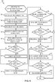
FIG. 6 is a flowchart illustrating a method for tracking exercise and personal security with a wearable wireless portable device; and -
FIG. 7 is a flowchart illustrating a method for processing exercise data and personal security data generated by one or more wearable wireless portable devices. -
FIG. 8 is a communication diagram illustrating a low-power short range communication link between a wearable wireless device and a mobile device. -
FIG. 9 is a process flow diagram of an embodiment method for selecting a communication path between a wearable wireless portable device and a telecommunication network. -
FIG. 10A is a process flow diagram of another embodiment method for selecting a communication path between a wearable wireless portable device and a telecommunication network. -
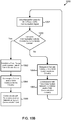
FIG. 10B is a process flow diagram of an embodiment wearable wireless portable device method of sending and receiving information to and from a telecommunication network. -
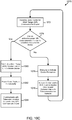
FIG. 10C is a process flow diagram of an embodiment method of de-energizing resources in the wearable wireless portable device when it is in close proximity to a mobile device. -
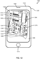
FIG. 11 is a circuit block diagram of a wearable wireless portable device suitable for use with the various embodiments. -
FIG. 12 is a circuit block diagram of a mobile device suitable for use with the various embodiments. - The various embodiments will be described in detail with reference to the accompanying drawings. Wherever possible, the same reference numbers will be used throughout the drawings to refer to the same or like parts. References made to particular examples and implementations are for illustrative purposes, and are not intended to limit the scope of the invention or the claims.
- The word "exemplary" is used herein to mean "serving as an example, instance, or illustration." Any embodiment described herein as "exemplary" is not necessarily to be construed as preferred or advantageous over other embodiments.
- In this description, the term "application" may also include files having executable content, such as: object code, scripts, byte code, markup language files, and patches. In addition, an "application" referred to herein, may also include files that are not executable in nature, such as documents that may need to be opened or other data files that need to be accessed.
- The term "content" may also include files having executable content, such as: object code, scripts, byte code, markup language files, and patches. In addition, "content" referred to herein, may also include files that are not executable in nature, such as documents that may need to be opened or other data files that need to be accessed.
- As used in this description, the terms "component," "database," "module," "system," and the like are intended to refer to a computer-related entity, either hardware, firmware, a combination of hardware and software, software, or software in execution. For example, a component may be, but is not limited to being, a process running on a processor, a processor, an object, an executable, a thread of execution, a program, and/or a computer. By way of illustration, both an application running on a computing device and the computing device may be a component. One or more components may reside within a process and/or thread of execution, and a component may be localized on one computer and/or distributed between two or more computers. In addition, these components may execute from various computer readable media having various data structures stored thereon. The components may communicate by way of local and/or remote processes such as in accordance with a signal having one or more data packets (e.g., data from one component interacting with another component in a local system, distributed system, and/or across a network such as the Internet with other systems by way of the signal).
- The term "computing device" is used herein to refer to any one or all of servers, personal computers, laptop computers, tablet computers, mobile devices, cellular telephones, smartbooks, ultrabooks, palm-top computers, personal data assistants (PDA's), wireless electronic mail receivers, multimedia Internet enabled cellular telephones, Global Positioning System (GPS) receivers, wireless gaming controllers, and other similar electronic devices that include a programmable processor and circuitry for wirelessly sending or receiving information.
- The terms "mobile device," "wireless device" and "wireless node" are used herein to refer to any electronic device that includes circuitry for wirelessly sending and/or receiving information, and may include any one or all of cellular telephones, personal or mobile multi-media players, watches, wrist displays, smartphones, personal or mobile multi-media players, personal data assistants (PDA's), laptop computers, tablet computers, ultrabooks, palm-top computers, wireless electronic mail receivers, multimedia Internet enabled cellular telephones, wireless gaming controllers, and similar personal electronic devices which include circuitry for sending and/or receiving wireless communication signals.
- The term "wireless-enabled device" is used herein to refer to any electronic device that includes a radio frequency (RF) radio or circuitry for wirelessly sending or receiving information via a short wave wireless technology, such as Wi-Fi and Bluetooth®, and thus may encompass many commercially available mobile devices, medical devices, personal computers, cameras, projectors, and other similar electronic devices. Details of the Wi-Fi standards and technologies are set forth in Institute of Electrical and Electronics Engineers' (IEEE) 802.11 standards, which are herein incorporated by reference for details related to the communication technologies.
- The term "Bluetooth®-enabled device" is used herein to refer to any electronic device that includes a radio frequency (RF) radio and a processor or circuitry for implementing the Bluetooth® protocol stack/interface. Bluetooth® is an open standard for short-range radio frequency (RF) communications. Details of the Bluetooth® standards, interfaces, and technology are set forth in Bluetooth® Special interest Group (SIG) Specification of the Bluetooth® System Version 4.0 June 30, 2010, which is herein incorporated by reference in its entirety.
- The various embodiments may be implemented using a variety of communication protocols, but are described herein using Bluetooth® and Bluetooth®-related terminology as a convenient example of a communications technology for wirelessly connecting electronic devices located within a relatively short distance of one another (e.g., 100 meters). However, the examples referring to Bluetooth®, and other references to the Bluetooth® herein, are for illustration purposes only, and are not intended to limit the descriptions or the claims to that particular standard. Therefore, the scope of the claims should not be construed as requiring Bluetooth® unless specifically recited in the claims.
- As discussed above, mobile devices (e.g., smartphones, etc.) are quickly becoming a necessary and indispensible tool for navigating modern society, yet there are times when it is not convenient for consumers to carry a conventional cellular-capable mobile device (e.g., while exercising, etc.).
- The various embodiments provide a lightweight, power efficient, and wearable wireless portable device ("WWPD") configured to communicate with a more conventional and feature-rich mobile device (e.g., smartphone, etc.) via low-power short range communication technologies (e.g., Bluetooth®, WiFi, etc.) when in close proximity to the mobile device, and provide the user access to cellular, telecommunication and/or wide area networks when not in close proximity to the mobile device. The wearable wireless portable device allows the user to continue having cellular/network connectivity when he/she is not carrying a cellular or network-enabled mobile device, but does not require the bulky, complex and/or power hungry circuitry or hardware typically included in conventional mobile devices. The wearable wireless portable device may transition between the different types of cellular and wireless communication technologies seamlessly and without user interaction.
- The wearable wireless portable device may be configured to automatically establish wide area network (WAN) connectivity when it is not in close proximity to the mobile device and/or when a low power short-range communication link cannot be established with the mobile device. WAN connectivity may be achieved via a cellular telephone network connection between a cellular transceiver in the wearable wireless portable device to a base state in a cellular telecommunication network.
- The wearable wireless portable device may be further configured to enter a low power state, turn off its wide area network (WAN) and/or cellular communications circuitry, and/or automatically establish a low power direct communication link to the mobile device when it is in close proximity to the mobile device. The wearable wireless portable device may also be configured to automatically disable or reduce the power consumption of any or all of the resources or components included the device when it is in close proximity to the mobile device and/or when a low power direct communication link is established with the mobile device. Example of device resources or components that may be disabled in such a situation include a Global Positioning System (GPS) receiver, a WAN modem or transceiver, a communication bus, voltage rails, sensors, and processors.
- In an embodiment, the wearable wireless portable device may be configured to use the direct communication link to send and receive communication messages to and from a telecommunication network or WAN via the network connectivity of the mobile device. The wearable wireless portable device mobile device may also be configured to send and receive messages to and from the mobile device via the direct communication link.
- In an embodiment, the wearable wireless portable device may be configured to register with a server or service that routes the communications to and from the wearable device, and to send/receive communications to and from the server or service.
- In various embodiments, the wearable wireless portable device may be a wrist display, badge, tag, bracelet, patch, belt buckle, medallion, pen, key chain, or any other device that may be worn or carried by a user.
- As mentioned above, the wearable wireless portable device may be configured to enter a low power state and turn off WAN and cellular communications circuitry when it is in close proximity to the mobile device. The wearable wireless portable device may also be configured to place the one or more processors and/or device resources (e.g., GPS receiver, memory unit, communication bus, etc.) in a low power state when it is in close proximity to the mobile device and/or when a low power direct communication link is established with the mobile device. These features reduce the amount of power consumed by the wearable wireless portable device, extending its battery life and/or reducing the size and weight of its battery. The above mentioned features also enable a wireless service provider to charge consumers less for their services, since a large portion of the wearable wireless portable device's network connectivity and communications may be achieved via the network connectivity of a second device (e.g., the mobile device).
-
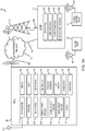
FIG. 1A is an illustration of asystem 100 that includes a wearable wirelessportable device 105A coupled to awireless communications network 142. Many of the system elements illustrated inFIG. 1A are coupled via communications links 103 to thewireless communications network 142. - The links 103 illustrated in
FIG. 1A may include wired or wireless links. Wireless links include, but are not limited to, radio-frequency ("RF") links, infrared links, acoustic links, and other wireless mediums. Thewireless communications network 142 may include a wide area network ("WAN"), a local area network ("LAN"), the Internet, a Public Switched Telephony Network ("PSTN"), a paging network, or a combination thereof. Thewireless communications network 142 may be established by broadcast RF transceiver towers 110B. However, one of ordinary skill in the art recognizes that other types of communication devices besides broadcast RF transceiver towers 110B are included within the scope of the invention for establishing thewireless communications network 142. The wearable wireless portable device ("WWPD") 105A is shown to have anRF antenna 110A so that a respective wearable wirelessportable device 105A may establish wireless communication links 103 with thewireless communications network 142 via broadcast RF transceiver towers 110B. - The wearable wireless
portable device 105A may include a plurality of software and/or hardware components, such as the illustrated radio-frequency ("RF")transceiver 115, global positioning satellite (GPS)module 120A, biological or physiological monitor(s) 125A, exercise orsports activity module 130A,personal security module 135A,entertainment module 140,camera 145,speaker 150,display 155,user interface module 160,time module 165,portability hardware 170,web browser module 175,power supply 180, andmicrophone 360. The wearable wirelessportable device 105A may include a processor or central processing unit ("CPU") 390 as illustrated inFIG. 1B and described below. The processor/CPU 390 may be configured with processor executable instructions to perform the functions described herein or it may have several dedicated circuits that provide the functions described herein. - The
RF transceiver 115 may be coupled to theRF antenna 110A. TheRF transceiver 115 may support one or more multiple RF communication types. For example, theRF transceiver 115 may support cellular phone type RF communications. Other communication types include, but are not limited to, fixed wireless, portable communication systems ("PCS"), or satellite communications systems. TheRF transceiver 115 may provide for multiple access communications, in accordance with any standard or protocol, such as, for example, code division multiple access ("CDMA"), time division multiple access ("TDMA"), frequency division multiple access ("FDMA"), or Global System for Mobile communications ("GSM"), or any combination thereof. - The
RF transceiver 115 in combination with thewireless communications network 142 may also support QChat® service type instantaneous communications. QChat® is a software application developed by Qualcomm Internet Services (QIS), a division of Qualcomm, Inc. and part of the Qualcomm Wireless and Internet group. QChat® provides a reliable method of instant connection and two-way communication between users who may be in different and who are operating within the same type of network architecture. QChat® may include a software application developed for the Binary Runtime Environment for Wireless ("BREW") platform. - "Press-to-Transmit" ("PTT") is a method of conversing on half-duplex communication lines for 3G and 4G networks. QChat® handsets and server software as of this writing allow users of the wearable wireless
portable device 105A to connect instantaneously with other QChat® users anywhere in the world with the push of a button. In addition, the QChat® service enables one-to-one (private) and one-to-many (group) calls over the 3G and 4G networks. - As understood by one of ordinary skill in the art, QChat® may use standard Voice over Internet Protocol (VoIP) technologies. Voice information may be sent in digital form over internet protocol ("IP") data networks in discrete packets rather than traditional circuit-switched protocols such those used in the public switched telephone network ("PSTN").
- The
RF transceiver 115 may also support short messaging system (SMS) functions such as texting. TheRF transceiver 115 may allow the operator of the wearable wirelessportable device 105A to forward inbound or incoming phone calls to a text to speech engine that may include software and/or hardware which are part of theuser interface module 160. Alternatively, the text to speech engine hardware and/or software may be part of aserver 111, which may receive phone calls that are forwarded to it by the wearable wirelessportable device 105A. - The
GPS module 120A may include hardware and/or software that supports the United States Global Positioning System ("GPS") or any other location position system of functionality. Thus, it should be understood that other global navigation satellite systems ("GNSS") are included within the scope of this application, and may also be supported by hardware and/or software executed by the wearable wirelessportable device 105A. Other GNSS or Satellite Positioning Systems ("SPS") include, but are not limited to, the Russian GLONASS system, and the European Galileo System. TheGPS module 120A may provide an operator of the wearable wirelessportable device 105A with a current set of the geographical coordinates for the location of theWWPD 105A. The wearable wirelessportable device 105A may also provide maps showing the geographical coordinates on thedisplay 155. TheGPS module 120A may also transmit its calculated geographical coordinates using theRF transceiver 115 over thewireless communications network 142 to aremote server 111, a second wearable wireless portable device (WWPD) 105B, and/or aportable computing device 107. - The wearable wireless
portable device 105A may include one or more biological orphysiological monitor modules 125A. These monitormodules 125A may check and track one or more physiological parameters. Exemplary measured physiological and/or calculated parameters include, but are not limited to: heart rate, calories burned, variability in heart rate, breathing rate, arrhythmia of the heart (if any), general rhythm and functioning of the heart, blood pressure, abnormal body movements (convulsions), body position, general body movements, body temperature, presence and quantity of sweat, oxygenation, and glucose levels in the blood. Themonitor modules 125A may work in concert or in conjunction with one ormore sensors 210 as described inFIG. 2 discussed below.Such sensors 210 may include, but are not limited to, heart rate sensors, blood pressure sensors, strain gauges, gyroscopes, accelerometers, pedometers, thermometers, thermocouples, glucometers, and other similar sensors as understood by one of ordinary skill in the art. - The
monitor modules 125A and thesensors 210 ofFIG. 2 may work in concert and/or in communication with one or more exercise orsports activity modules 130A. The exercise orsports activity modules 130A may be designed for specific physical activities that may include, but are not limited to, jogging, running, walking, bicycling, swimming, rowing, strength training, yoga, mountain biking, skiing, hiking, and mountain climbing. The system may track other similar physical activities that include all sports and sports related activities. - Each exercise or
sports activity module 130A may be tailored for a specific physical activity. For example, a joggingsports activity module 130A may track the heart rate, calories burned, as well as the distance traveled by the operator of the wearable wirelessportable device 105A. A swimmingsports activity module 130A may also track and monitor heart rate, calories burned, water temperature, as well as the number of laps taken by the operator of the wearable wirelessportable device 105A. Thesports activity module 130A may also track and monitor time according to the activity selected by the wearable wirelessportable device 105A. - In addition to tracking the exercise or sports activity of the operator of the wearable wireless
portable device 105A, the exercise orsports activity module 130A may be configured to receive performance data that is transmitted to the wearable wirelessportable device 105A from a second wearable wirelessportable device 105B as illustrated inFIG. 1A . In one embodiment, the wearable wirelessportable device 105A may receive data regarding other operators of another wearable wirelessportable device 105B that may be participating in the same exercise or sports activity of the operator of the wearable wirelessportable device 105A. Such performance data may include, but is not limited to, (1) geographical locations of other athletes or exercisers that may be shown ondisplay 155, and (2) specific metrics of other athletes and exercisers. The specific metrics may include, but are not limited to, calories burned, current speed, current exercise rate, or athletic rate, etc. Performance data may include data from famous athletes who have uploaded and stored their exercise or sports activity data. In this way, the wearable wirelessportable device 105 may foster competition among multiple athletes and/or exercisers in which these people may be significantly geographically diverse (i.e., separate from one another), such as people comparing performance data to one another who live in different towns, cities, states, countries, etc. - The exercise or
sports activity module 130A may also track and monitor benchmarks associated with stored data such as benchmarks recorded and stored in theremote server 111 by famous or noteworthy athletes. In other words, the exercise orsports activity module 130A may provide a continuous comparison of a current exercise or sports activity of the operator of the wearable wirelessportable device 105A to stored results of a famous or noteworthy athlete who has uploaded and stored his or her exercise or sports activity data (also referred to as performance data throughout this document). Details about these comparative functions performed by the exercise orsports activity module 130A will be described in further detail below in connection withFIG. 3 andFIG. 4 . - The
personal security module 135A may include hardware and/or software modules that allow the operator to select from a plurality of personal security features and functions. For example, thepersonal security module 135A may activate a function such that the position of the wearable wirelessportable device 105A as monitored and detected by theGPS module 120A may be sent over thewireless communications network 142. This data may be received by theserver 111. In this way, a third-party may monitor movement of the wearable wirelessportable device 105A which has activated thepersonal security module 135A. Thepersonal security module 135A may include user-defined functions such as an alert or an alarm button that may be depressed by the operator of the wearable wirelessportable device 105A. The alert or alarm button may be depressed by the operator if he or she is experiencing a security issue, such as a robbery, kidnapping, assault, etc. - The
personal security module 135A may also be programmed to provide periodic updates of the location of the wearable wirelessportable device 105A as selected by the operator. Thepersonal security module 135A may generate periodic text messages indicating that the status of the operator is good. Likewise, thepersonal security module 135A may also operate as a "kill switch." For this feature, the operator is required to push a button which transmits a message stating that the "operator is OK" according to certain time intervals and/or locations or both. When the operator of the wearable wirelessportable device 105A does not push the button after a period of time and/or at a location or both, then an alarm signal may be triggered and generated by the wearable wirelessportable device 105A. This alarm signal is communicated over thewireless communications network 142 to theserver 111. The alarm signal in an exemplary embodiment may take the form of a text message. The generation of text messages may consume very little or low bandwidth. The text message functions may operate like conventional wireless devices which utilize 3G and 4G wireless connections. - The
personal security module 135A may support other types of security features and/or functions. Such other types of security features and/or functions may include an alert feature that allows the operator of the wearable wirelessportable device 105A to send an alert status to theserver 111. With this alert status, a remote operator such as a second wearable wirelessportable device 105B or aportable computing device 107 may be notified to start tracking or monitoring the status of the first wearable wirelessportable device 105A. - In other words, the
personal security module 135A may support an alert feature that does not require immediate action with respect to a party monitoring the location of the wearable wirelessportable device 105A. This alert feature may only require the party who has access to theserver 111 to start focusing on the location and movement of the wearable wirelessportable device 105A until the operator of the wearable wirelessportable device 105A indicates that further monitoring by the third party is no longer needed. - The
personal security module 135A may also support emergency functions and/or features such as a 911 emergency call feature. This means when the 911 emergency call feature is activated, thepersonal security module 135A may be programmed to send the current location of the wearable wirelessportable device 105A along with a predetermined or canned message. The canned message may include a text message and/or a voice message that identifies the name of the operator of the wearable wirelessportable device 105A along with instructions for emergency personnel /first responders to come to the rescue of the operator immediately. Thepersonal security module 135A may also support specific emergency functions such as identifying the category or type of emergency and requesting emergency assistance corresponding to the category or type selected by the operator of the wearable wirelessportable device 105A. - That is, the
personal security module 135A may support an emergency medical function, an emergency police function, and an emergency fire function, or any combination thereof. In this way, the operator of the wearable wirelessportable device 105A may select the type of emergency that may be experienced by the operator so that proper emergency personnel/first responders are appropriately notified and requested to arrive at the location of the wearable wirelessportable device 105A. - As noted above, the wearable wireless
portable device 105A may also include one ormore entertainment modules 140. The one ormore entertainment modules 140 may support functions and/or features or a combination thereof that include, but are not limited to, audio players, video players, video games, and other entertainment functions. For example, theentertainment module 140 may include an MP3 player for playing audio files that include music files. - The wearable wireless
portable device 105A may also include acamera 145 that may support conventional photographs as well as video. Further details about thecamera 145 will be described below in connection withFIG.1B . The wearable wirelessportable device 105A may also include aspeaker 150, amicrophone 360, adisplay 155, and auser interface module 160. Theuser interface module 160 may be coupled to thespeaker 150, thedisplay 155, and themicrophone 360. - The
user interface module 160 may support or be part of an operating system ("OS") that is integrated with the graphics shown on adisplay 155 and which may support touch and keyed-in commands as well as voice activated commands. Theuser interface module 160 may provide for a simulated keyboard on thedisplay 155. Alternatively, a physical keyboard orkeypad 374 such as illustrated inFIG. 1B may be part of theuser interface module 160. - The wearable wireless
portable device 105A may also include one ormore time modules 165 that may be coupled to thedisplay 155, thespeaker 150, and the exercise orsports activity modules 130A. Thetime modules 165 may track current time as well as times and other time zones throughout the world. Thetime modules 165 may be accessed and may provide data to the exercise orsports activity modules 130A such as, but not limited to, lap time, running or jogging rate, and other similar time features. Thetime modules 165 may be coupled to thedisplay 155. The times tracked by thetime modules 165 may be displayable to the operator of the wearable wirelessportable device 105A. - The wearable wireless
portable device 105A may also includeportability hardware 170 which may take on various different forms. For example, theportability hardware 170 may include physical structures such as one or more bands coupled together so the wearable wirelessportable device 105A is worn as a bracelet or like a watch. In other cases, theportability hardware 170 may include other bands, straps, or fasteners, so the wearable wirelessportable device 105A may be worn on the other parts of the human anatomy. For example, theWWPD 105 A may be worn on the arm of a person as well as around the torso of a person. As a further example, theWWPD 105 may be worn as a pendant around a human neck and/or clipped-on to clothing. - The wearable wireless
portable device 105A may also include aweb browser module 175 that is coupled to thedisplay 155B,user interface module 160, and theRF transceiver 115. Theweb browser module 175 may allow the operator to access the Internet as well as allowing various modules such as theGPS module 120A and the exercise orsports activity modules 130A to upload or download particular information. - The wearable wireless
portable device 105A may also include apower supply 180. Thepower supply 180 may include, but is not limited to, batteries, capacitors, solar cells, mechanical power generation devices (i.e. self winding equipment), and any combination thereof as well as similar power supplies 18 known to one of ordinary skill the art. - In an embodiment, the wearable wireless
portable device 105A may include a power management system configured to selectively deactivate, power down, de-energize, or reduce the power consumption needs of any or all of the components, resources (e.g., sensors, etc.), processors, modules, systems, and sub-systems of the wearable wirelessportable device 105A based on determining that a communication link has been established to another device (e.g.,WWPD 105B, mobile device, etc.) or in response to determining that the wearable wirelessportable device 105A and the second device duplicate a functionality, are capable of performing the same or similar operations, or are capable of providing the user with the same or similar functionality or service. - The
server 111 may include one or more modules which mirror those which are contained within or part of the wearable wirelessportable device 105A. That is, theserver 111 may include one ormore GPS modules 120B, one or more exercise orsports activity modules 130B, one or more biological orphysiological monitor modules 125B, and one or morepersonal security modules 135B. The modules of theserver 111 may be complementary relative to the modules of the wearable wirelessportable device 105A and may work in concert with the modules of the wearable wirelessportable device 105A. - As noted previously, the
server 111 may communicate with other wearable wirelessportable devices 105B as well as otherportable computing devices 107. Otherportable computing devices 107 may include handheld computers, laptop computers, and desktop computers. - Referring to
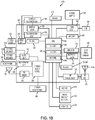
FIG. 1B , an exemplary, non-limiting embodiment of a wearable wirelessportable device 105A is shown. The wearable wirelessportable device 105A includes an on-chip system 322 that includes amulticore CPU 390. Themulticore CPU 390 may include azeroth core 394, afirst core 396, and anNth core 398. According to alternate exemplary embodiments, theCPU 390 may also include those of single core types and not one which has multiple cores. - As illustrated in
FIG. 1B , adisplay controller 328 and atouch screen controller 330 are coupled to themulticore CPU 390. In turn, thedisplay 155 external to the on-chip system 322 is coupled to thedisplay controller 328 and thetouch screen controller 330. -
FIG. 1B further shows that avideo encoder 334, e.g., a phase alternating line (PAL) encoder, a sequential color a memoire (SECAM) encoder, or a national television system(s) committee (NTSC) encoder, is coupled to themulticore CPU 390. Further, avideo amplifier 336 is coupled to thevideo encoder 334 and the touch screen display 108. Also, avideo port 338 is coupled to thevideo amplifier 336. As shown inFIG. 1B , a universal serial bus (USB)controller 340 is coupled to themulticore CPU 390. Also, aUSB port 342 is coupled to theUSB controller 340.Memory 392 and a subscriber identity module (SIM)card 346 may also be coupled to themulticore CPU 390. - Further, as shown in
FIG. 1B , adigital camera 145 may be coupled to themulticore CPU 390. In an exemplary embodiment, thedigital camera 145 is a charge-coupled device (CCD) camera or a complementary metal-oxide semiconductor (CMOS) camera. - As further illustrated in
FIG. 1B , a stereo audio coder-decoder (CODEC) 350 may be coupled to themulticore CPU 390. Moreover, anaudio amplifier 352 may coupled to thestereo audio CODEC 350. In an exemplary embodiment, afirst stereo speaker 150A and asecond stereo speaker 150B are coupled to theaudio amplifier 352.FIG. 1B shows that amicrophone amplifier 358 may be also coupled to thestereo audio CODEC 350. Additionally, amicrophone 360 may be coupled to themicrophone amplifier 358. In a particular embodiment, a frequency modulation (FM)radio tuner 362 may be coupled to thestereo audio CODEC 350. Also, an FM antenna is coupled to theFM radio tuner 362. Further,stereo headphones 366 may be coupled to thestereo audio CODEC 350. -
FIG. 1B further illustrates that a radio frequency ("RF")transceiver 115 may be coupled to themulticore CPU 390. AnRF switch 370 may be coupled to the RF transceiver 368 and anRF antenna 110A. As shown inFIG. 1B , akeypad 374 may be coupled to themulticore CPU 390. Also, a mono headset with amicrophone 376 may be coupled to themulticore CPU 390. Further, avibrator device 378 may be coupled to themulticore CPU 390. -
FIG. 1B also shows that thepower supply 180 may be coupled to the on-chip system 322. According to one embodiment, thepower supply 180 is a direct current (DC) power supply that provides power to the various components of the wearable wirelessportable device 105A that require power. Further, in a particular embodiment, thepower supply 180 is a rechargeable DC battery or a DC power supply that is derived from an alternating current (AC) to DC transformer that is connected to an AC power source. -
FIG. 1B further illustrates anetwork card 388 that may be used to access a data network, e.g., a local area network, a personal area network, or any other network. Thenetwork card 388 may be a Bluetooth network card, a WiFi network card, a personal area network (PAN) card, a personal area network ultra-low-power technology (PeANUT) network card, or any other network card well known in the art. Further, thenetwork card 388 may be incorporated into a chip, i.e., thenetwork card 388 may be a full solution in a chip, and may not be aseparate network card 388. - The
multicore CPU 390 may be coupled to software and/or hardware embodiments of themodules FIG. 1A . These modules 120-140 may take the form of software and/or hardware, such as, but not limited to an application integrated circuit (ASIC), and/or firmware. These modules 120-140 ofFIG. 1A are generally responsible for providing the global positioning functions, bio monitoring functions, exercise /athletic performance tracking functions, personal security functions, and entertainment functions as described above in connection withFIG. 1A . - As depicted in
FIG. 1B , the touch screen ordisplay 155, thevideo port 338, theUSB port 342, thecamera 145, the first stereo speaker 354, the second stereo speaker 356, themicrophone 360, theFM antenna 364, thestereo headphones 366, theRF switch 370, the RF antenna 372, thekeypad 374, the mono headset/microphone 376, thevibrator device 378, and the power supply 380 are external to the on-chip system 322. - According to another particular embodiment of the system, one or more of the method steps described herein may be stored in the
memory 392 as computer program instructions, such as themodules portable device 105A as illustrated inFIG 1A . - These instructions may be executed by the
multicore CPU 390 to perform the method steps described herein. Further, themulticore CPU 390 andmemory 392 of the wearable wirelessportable device 105A, or a combination thereof may serve as a means for executing one or more of the method steps described herein. -
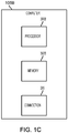
FIG. 1C illustrates various components of an embodiment computing device capable of mobile operation that may be in the form of wirelessportable device 105B. Specifically,FIG. 1C illustrates that a wirelessportable device 105B may include aprocessor 390B, amemory 392B, and aconnection 295 module. Theprocessor 390B may be configured by software instructions to perform a variety of methods, including the methods of the various embodiments described herein. For example, theprocessor 390B may include a programmable processor (e.g., x86, ARM), a digital signal processor ("DSP"), an application specific integrated circuit ("ASIC"), a field programmable gate array ("FPGA"), etc. - The
processor 390B may be coupled to and/or execute modules 120-140, which are described above. The modules 120-140 may take the form of software and/or hardware, such as, but not limited to an application integrated circuit ("ASIC"), and/or firmware. These modules 120-140 ofFIG. 1A are generally responsible for providing the global positioning functions, bio monitoring functions, exercise /athletic performance tracking functions, personal security functions, and entertainment functions as described above in connection withFIG. 1A . - The
memory 392B may be any optical disk storage, any magnetic disk storage, or any other medium operable to store logic and/or data accessible by the computer. Thememory 392B may include random access memory ("RAM"), read-only memory ("ROM"), electrically erasable programmable read-only memory ("EEPROM"), or any type of solid-state memory that is suitable for compact electronic packaging for a wearable wirelessportable device 105. - The
connection 295 may generally allow connectivity to other computers, wireless devices, laptops, servers, etc. Theconnection 295 may include a network interface card ("NIC"), a modem, a universal serial bus port ("USB"), a Firewire port, a 3G/4G wireless modem, a near-field communication connection ("NFC"), etc. Theconnection 295 may be any other wired connection, any other wireless connection, any other magnetic connection, any other visual connection, any other audible connection, etc. -
FIG. 2 is a diagram of an example wearable wirelessportable device 105 having security monitoring and communication functions contained within anatomical mountinghardware 170. In the exemplary embodiment illustrated inFIG. 2 , theanatomical mounting hardware 170 includes a bracelet or ornamental shell suitable for wearing on anarm 255 of ahuman subject 250. As discussed above, the wearable wirelessportable device 105 is not limited to anatomical mountinghardware 170 suitable only for mounting on anarm 255. The mountinghardware 170 may include other elements such as a chain, pin, clip or other type of mechanical fasteners such that the wearable wirelessportable device 105 may be worn on other regions of the body. For example, theWWPD 105 may take the form as a pendant for wearing around a neck. TheWWPD 105 may include a unit for attaching to a bicep, or a unit worn on the waist of ahuman subject 250. - In the exemplary embodiment illustrated in
FIG. 2 , thedisplay 155A of the wearable wirelessportable device 105 may provide numerous pieces of information for the operator such as, but not limited to, the current time of day, and aheart rate 182 of the operator orhuman subject 250. Thedisplay 155A may also show otheruser interface elements 160A-160G as will be described in further detail below. - The wearable wireless
portable device 105 may be coupled to one or more different types ofsensors 210. In the exemplary embodiment illustrated inFIG. 2 , thesensor 210 may include a heart rate sensor. However, other types of sensors are included within the scope of the invention and may include, but are not limited to, breathing sensors, oxygenation sensors, perspiration sensors, blood pressure sensors, glucose meters, temperature sensors, and other like sensors. Other like sensors may measure various different types of physiological parameters that are helpful in monitoring and tracking performance during exercise and athletic activities. - In the exemplary embodiment illustrated in
FIG. 2 , theheart rate sensor 210 may be supported by astrap 215. Other mounting hardware besides thestrap 215 for thesensor 210 may be employed as understood by one of ordinary skill in the art. The wearable wirelessportable device 105 may be coupled to thesensor 210 via awireless connection 205A. Wireless connections include, but are not limited to, radiofrequency couplings, magnetic couplings, infrared, and acoustic couplings. Other wireless connections not specifically mentioned are well within the scope of the invention as understood by one of ordinary skill in the art. In an alternative embodiment, awired connection 205B may be used to couple thesensor 210 to the wearable wirelessportable device 105. - The seven
user interface elements 160A-160G may be suitable for adisplay 155A that supports touch-screen type features. This means that for the sevenuser interface elements 160A-160G, when the operator touches one or more of theseuser interface elements 160A-160G, then one or more functions and/or features supported by the wearable wirelessportable device 105 may become active or accessed by the operator/human subject 250. - The first
user interface element 160A may include an alert button for creating an alert message as described above in connection withFIG. 1A . Such an alert feature may include one that allows the operator of the wearable wirelessportable device 105A to send an alert status to theserver 111. The server may in turn transmit the alert to a remote operator such as a second wearable wirelessportable device 105B or aportable computing device 107 as illustrated inFIG. 1A . Theportable computing device 107 may be notified to start tracking or monitoring the status of the first wearable wirelessportable device 105A. - In other words, the
personal security module 135A of the wearable wirelessportable device 105 may support an alert feature that does not require immediate action with respect to a party monitoring the location of the wearable wirelessportable device 105A. This alert feature, when activated by the firstuser interface element 160A, may only require the party who has access to theserver 111 to start focusing on the location and movement of the wearable wirelessportable device 105A. The party may stop monitoring the location and movement of theWWPD 105A when the operator of theWWPD 105A indicates that further monitoring by the third party is no longer needed - The second
user interface element 160B may support an immediate or urgent response feature as described above in connection withFIG. 1A . That is, the seconduser interface element 160B may support emergency functions and/or features such as a 911 emergency call feature. This means when the 911 function or "Emergency" button feature associated withuser interface element 160B is activated, thepersonal security module 135A may be programmed to send the current location of the wearable wirelessportable device 105A. TheWWPD 105A may also send a message that may include a text message and/or a voice message. The text message and/or voice message may identify the name of the operator of the wearable wirelessportable device 105A along with instructions for emergency personnel or first responders to come to the rescue of the operator substantially immediately. - The
personal security module 135A as activated by the seconduser interface element 160B may also support specific emergency functions such as identifying the category or type of emergency. The seconduser interface element 160B may request emergency assistance corresponding with the category or type selected by the operator of the wearable wirelessportable device 105A. This means that thepersonal security module 135A may support an emergency medical function, an emergency police function, and an emergency fire function, or any combination thereof. - In this way, the operator of the wearable wireless
portable device 105A may select the type of emergency that may be experienced by the operator after the seconduser interface element 160B "Emergency" button is activated. This allows proper emergency personnel or first responders to be appropriately notified and requested to arrive at the location of the wearable wirelessportable device 105A. - The third
user interface element 160C may support a function in which the operator desires to record and store current exercise or competition/performance data with the wearable wirelessportable device 105. The thirduser interface element 160C may also activate the competition feature described above in connection withFIG. 1A . - The third
user interface element 160C may activate the exercise orsports activity module 130A such that theWWPD 105A receives performance data that is transmitted to the wearable wirelessportable device 105A from other wearable wirelessportable devices 105B as illustrated inFIG. 1A . Similarly, activation of the thirduser interface element 160C may also cause the exercise orsports activity module 130A to transmit the current performance data of the operator/human subject 250 of theWWPD 105A over thewireless communications network 142 to theserver 111. - In one exemplary embodiment, activation of the third
user interface element 160C may initiate the feature in which the wearable wirelessportable device 105A receives data regarding other operators ofother WWPDs 105B that may be participating in the same exercise or sports activity of the operator/human subject 250 of aparticular WWPD 105A. Such performance data may include, but is not limited to, geographical locations of other athletes or exercisers that may be shown ondisplay 155, and specific metrics of other athletes such as calories burned, current speed, current exercise or athletic rate, etc. In this way, the wearable wirelessportable device 105 may foster competition among multiple athletes and/or exercisers in which these people may be significantly geographically diverse (separate from one another). For example, this may include people comparing performance data to one another who live in different towns, cities, states, countries, etc. - The fourth
user interface element 160D may activate a "menu" function that may display various options and/or functions that may be supported by the wearable wirelessportable device 105. This fourthuser interface element 160D may cause a menu to be shown on thedisplay 155A so the operator/human subject 250 may select from the menu elements. - The fifth
user interface element 160E may support/activate the "Push-To-Talk" or "Push-To-Transmit" feature described in connection withFIG. 1A above. In one embodiment, activation of the fifthuser interface element 160E may initiate QChat®-based instantaneous communications such that the operator/human subject 250 may conduct communications using thespeaker 150. As noted previously, QChat® is a software application which was developed by Qualcomm, Inc. based in San Diego, California. QChat® provides a reliable method of instant connection and two-way communication between users in different locations. QChat® allows users of the wearable wirelessportable device 105A to connect instantaneously with other QChat® users anywhere in the world with the push of a button, such as the fifthuser interface element 160E. - The sixth and seventh
user interface elements human subject 250 may track time for an exercise or other form of athletic activity. The six and sevenuser interface elements more time modules 165 as described above in connection withFIG. 1A . -
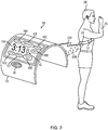
FIG. 3 is a diagram of a screen/display 155B for displayingexercise data 305A andcompetition data 305B for an operator of the wearable wirelessportable device 105. This screen/display 155B may be generated by the exercise orsports activity module 130A which may receive performance data transmitted to the wearable wirelessportable device 105A from other wearable wirelessportable devices 105B as illustrated inFIG. 1A . In other words, the wearable wirelessportable device 105A may receive data, likecompetition data 305B, related to or associated with other operators of other wearable wirelessportable devices 105B. Theseother WWPDs 105B may be participating in the same exercise or sports activity of the operator of the wearable wirelessportable device 105A. - Such performance data may include, but is not limited to, geographical locations of other athletes or exercisers that may be shown on
display 155. In one embodiment, specific metrics of other athletes and exercisers such as calories burned, current speed, and current exercise or athletic rate, etc. may be shown on thedisplay 155. In this way, the wearable wirelessportable device 105 may foster competition among multiple athletes and/or exercisers in which these people may be significantly geographically diverse (separate from one another). This includes people comparing performance data to others, who may live and compete in different towns, cities, states, countries, etc. - In the exemplary embodiment illustrated in
FIG. 3 , the exercise orathletic activity data 305A of the operator of the wearable wirelessportable device 105A may include information relating to the activity of bicycling. Theathletic data 305A shown ondisplay 155B may include information such as but not limited to, distance traversed by the operator during the activity, the amount of calories burned during the activity, the current heart rate of the operator, and the average speed in miles per hour (MPH). - As noted previously, the exercise or
sports activity module 130A may also track and monitor benchmarks associated with stored data such as benchmarks recorded and stored at aserver 111 by famous or noteworthy athletes. In one embodiment, the exercise orsports activity module 130A may provide a continuous comparison of a current exercise or sports activity of the operator of the wearable wirelessportable device 105A to stored results of a famous or noteworthy athlete. The famous athlete may have uploaded and stored his or her exercise or sports activity data (also referred to as performance data throughout this document). - In the exemplary embodiment illustrated in
FIG. 3 , thecompetition data 305B may include benchmarks set by a famous athlete. In this particular example, the famous athlete is in the bicycling field. Thiscompetition data 305B may have the same parameters as theathletic activity data 305A. In this particular example, thecompetition data 305B also includes distance traversed by the athlete at the same location as the operator during the activity, the amount of calories burned during the activity at the same stage for the athlete, the recorded heart rate of the athlete at the same stage of the activity, and the recorded average speed in miles per hour for the athlete at the same stage of activity. - As described above, the
competition data 305B may also include real-time information of another operator of a wearable wirelessportable device 105B. If the operator Jane was racing the operator Vance Legstrong in a live or current activity, then theathletic activity data 305A andcompetition data 305B would be current, and the parameters for the athletic activity being monitored by the two or more wearable wirelessportable devices - In addition to the
exercise data 305A and thecompetition data 305B, the wearable wirelessportable device 105, and specifically, the exercise orsports activity module 130A may also providerecommendations 305C to the operator so theexercise data 305A may become closer to thecompetition data 305B or possibly exceed thecompetition data 305B. For example, if Jane Doe is in a race against the operator Vance Legstrong, then the exercise module may try to help Jane win against Vance. In one embodiment, the exercise orsports activity module 130A may compare theexercise data 305A to thecompetition data 305B. The exercise orsports activity module 130A may also determine that if the operator of theWWPD 105A increases their average speed by at least six miles per hour, then the operator may be able to keep up with their competition in the athletic activity being tracked by thecompetition data 305B. -
FIG. 4 is a diagram of ascreen 155C for displaying a location of the wearable wirelessportable device 105A on amap 400 relative to geographical elements. Geographical elements may include streets 426, 428 and thescreen 155C may show afirst WWPD 105A relative to other locations 422, 424 of second andthird WWPDs 105B, 105C. In one embodiment, themap 400 may be generated by theGPS module 120A in combination with the exercise orsports activity module 130A. - As noted above, the
GPS module 120A may also transmit calculated geographical coordinates of theWWPD 105A over thewireless communications network 142 to theserver 111 using theRF transceiver 115. In this way, amap 400 may be displayed onother devices WWPD 105A. Inmap 400, the operator of the wearable wirelessportable device 105A is designated by reference character 420. Meanwhile, other wearable wirelessportable devices 105B, 105C have transmitted their respective geographical locations as indicated by reference characters 422 and 424. These coordinates of theWWPDs sports activity module 130A and theGPS module 120A. - The wearable wireless
portable devices FIG. 4 . However, other types of icons that may designate the type of activity being monitored may be used as understood by one of ordinary skill in the art. For example, instead of the ovals used inFIG. 4 , bicycle-shaped icons or runner-shaped icons may be used to denote bicycling or running. Other icon shapes and types representative of other activities may be used as understood by one of ordinary skill in the art. -
FIG. 5 is a diagram of a screen 500 of a remoteportable computing device 107 for displaying a location of the wearable wirelessportable device 105A relative to geographical elements such as streets 426, 428. Screen 500 may be generated based on the coordinates received from aGPS module 120A and information received from thepersonal security module 135A of wearable wirelessportable device 105A. - The
portable computing device 107 may be coupled to theserver 111 via thewireless communications network 142. Screen 500 may be generated in response to the alert function supported by thepersonal security module 135A which allows the operator of the wearable wirelessportable device 105A to send an alert status to theserver 111. These alerts may cause theportable computing device 107 to start tracking or monitoring the status of the first wearable wirelessportable device 105A. - In one embodiment, the
personal security module 135A may support an alert feature that does not require immediate action with respect to a party monitoring the location of the wearable wirelessportable device 105A, such as a party reviewing screen 500 ofFIG. 5 . This alert feature only may require the party who has access to theserver 111 to start focusing on the location and movement of the wearable wirelessportable device 105A. - For example, Jane Doe is a bicyclist who decided to generate a first alert 105A1 at time 3:20pm on September 30, 2010 as illustrated in
FIG. 5 . Jane activated this alert by pressing the alert button (e.g.,user interface element 160A ofFIG. 2 ). After traveling from location designated by the first alert 105A1 inFIG. 5 , Jane decided to cancel the alert status by pressing the alert button (i.e.,user interface element 160A ofFIG. 2 ) when she reached the second alert location indicated by the second alert 105A2 at 3:25pm inFIG. 5 . Jane decided to cancel the alert since she felt she was riding in a safer area compared to the location of her first alert 105A1 ofFIG. 5 . - The
GPS module 120A of aWWPD 105A may continuously transmit its location to theserver 111 such that this continuous movement data may be displayed in screen 500 for the remoteportable computing device 107. Screen 500 may support various user interfaces that allow an operator to communicate with the operator of the wearable wirelessportable device 105A. - For example, the first
user interface element 505 of the screen 500 may include a push-to-text feature that allows the operator of theportable computing device 107 to send text or simple messaging service ("SMS") messages to the operator of the wearable wirelessportable device 105A. A seconduser interface element 510 may include an on-screen button that allows the operator of theportable computing device 107 to get in contact with first responders such as police, fire, and rescue departments. Other user interface elements may be used as understood by one of ordinary skill in the art. -
FIG. 6 is a flowchart illustrating amethod 600 for tracking exercise and personal security with a wearable wireless portable communication device.Block 605 is the first step of themethod 600 in which the exercise orsports activity module 130A may receive a selection of the type of exercise that an operator of the wearable wirelessportable device 105 desires to track. Next, inblock 610 thepersonal security module 135A may receive a selection of one or more options for generating alerts that are transmitted to theserver 111 over thewireless communications network 142. Such options that may be selected include the exemplary firstuser interface element 160A as illustrated inFIG. 2 in which an operator of the wearable wirelessportable device 105 may activate an alert by selecting or touching the "alert button" on the screen/display 155A. - Next, in
block 615, the biological orphysiological monitor module 125A and/or the exercise orsports activity module 130A may display one or more biological or physiological outputs on thedisplay 155A. For example, aheart rate 182 may be displayed on the screen/display 155A as illustrated inFIG 2 . However, other physiological outputs and/or calculated parameters, like calories burned, etc. may be displayed as options selected by the operator. For example, an operator may decide to select options for displaying heart rate and calories burned simultaneously on the screen/display 155A. - In
block 620, the wearable wirelessportable device 105 may periodically transmit the tracked biological or physiological outputs as well as the geographical location of the wearable wireless portable device 105 (as determined by theGPS module 120A) to theserver 111. In block 625D, theuser interface module 160 may provide user interface elements for personal security such as the first and seconduser interface elements FIG 2 . - As described above, the first
user interface element 160A may be related to an alert function that may be selectable by the operator of the wearable wirelessportable device 105. The seconduser interface element 160B may support an emergency call function as described above. Other personal security functions that may be tracked by the wearable wirelessportable device 105 are included as understood to one of ordinary skill in the art. - In
decision block 630, thepersonal security module 135A may determine if an alert function has been selected by the operator of the wearable wirelessportable device 105. If the inquiry to decision block 630 is negative, then the "NO" branch is followed todecision block 640. If the inquiry to decision block 630 is positive, then the "YES" branch is followed to block 635 in which thepersonal security module 135A may transmit an alert to theserver 111 that may be translated into a graphical display such as screen 500 and specifically, the first alert 105A1 as illustrated inFIG. 5 . - Next, in
decision block 640, theRF transceiver module 115 in combination with thecentral processing unit 390 may determine if the operator of the wearable wirelessportable device 105 desires to conduct a telephone call. If the inquiry to decision block 640 is negative, then the "NO" branch is followed todecision block 650. If the inquiry to decision block 640 is positive, then the "YES" branch is followed to block 645 in which theRF transceiver 115 establishes call communications with theserver 111 and/or a cellular telephone network orwireless communications network 142.Decision block 640 may also correspond with an operator selecting the "Push-to-Talk" feature corresponding to theuser interface element 160E as illustrated inFIG. 2 . - In
decision block 650, theCPU 390 and/or theRF transceiver 115 may determine if the wearable wirelessportable device 105 is receiving an inbound call communications from theserver 111 or from a cellular communications network orwireless communications network 142. If the inquiry to decision block 650 is negative, then the "NO" branch is followed todecision block 670. If the inquiry to decision block 650 is positive, then the "YES" branch is followed to block 655 in which one or more options may be displayed on thedisplay 155 to explain how the operator of the wearable wirelessportable device 105 may handle a particular call. For example, an operator may elect to take the call and activate thespeaker 150. Alternatively, the operator may choose to ignore the call and transfer the call to a voicemail-to-text feature supported by theserver 111. - In
decision block 660, theCPU 390 may determine if a selection was made by the operator of the wearable wirelessportable device 105 to accept the inbound call. If the inquiry to decision block 660 is negative, then the "NO" branch is followed todecision block 670. If the inquiry to decision block 660 is positive, then the "YES" branch is followed to block 665 in which call communications are established with theserver 111 and/or a respective cellular telephone communication network orwireless communications network 142. - In
decision block 670, theGPS module 120A and or the exercise orsports activity module 130A may determine if an operator has selected an option to display a map and/or competition data. If the inquiry to decision block 670 is negative, then the "NO" branch is followed todecision block 680. If the inquiry to decision block 670 is positive, then the "YES" branch is followed to block 675. In this step, map 400 ofFIG. 4 may be displayed with a current location of the operator such as location 420 and the locations 422, 424 of other users. - In
decision block 680, theentertainment module 140 may determine if an operator of the wearable wirelessportable device 105 has selected an entertainment option. For example, an operator may select playing an audio file like an MP3 type audio file and or a video file in this block. If the inquiry to decision block 680 is negative, then themethod 600 ends. If the inquiry to decision block 680 is positive, then the "YES" branch is followed to block 685. In thisblock 685, theentertainment module 140 may execute one or more of the selected entertainment options, such as playing an audio file, a video file, or a game. Themethod 600 proceeds to the last block and then ends. -
FIG. 7 is a flowchart illustrating amethod 700 for processing exercise data and personal security data generated by one or more wearable wireless portable devices. The first block in themethod 700 which is typically executed by theserver 111 isblock 705. Inblock 705, theserver 111 may receive biological or physiological outputs corresponding to the options selected by the operator of a wearable wirelessportable device 105 that are transmitted over thewireless communications network 142 to theserver 111. - Next, in
block 710, theserver 111 may receive the current location of one or more wearable wirelessportable devices 105 that are generated byrespective GPS modules 120A. Inblock 715, theserver 111 may process the biological and/or physiological outputs according to the selected exercise option and store these results in memory. For example, theserver 111 may track and compare the current biological and or physiological outputs being transmitted over thewireless communications network 142 to base-line measurements and/or readings in order to determine if there are any problems for the operator of the wearable wirelessportable device 105. - Subsequently, in
decision block 720, the server may determine 110 if it has received one or more security alerts from one or more wearable wirelessportable devices 105. If the inquiry to decision block 720 is negative, then the "NO" branch is followed todecision block 735. If the inquiry to decision block 720 is positive, then the "YES" branch is followed to block 725 in which theserver 111 processes the alert according to preselected options and/or perimeters transmitted from the wearable wirelessportable device 105A. - In this
block 725, theserver 111 may generate screen 500 ofFIG. 5 and provide the interactiveuser interface elements portable computing device 107. Inblock 730, theserver 111 may relay the alert to one or more preselected users such as one or more other wearable wirelessportable devices 105B, 105C such as illustrated inFIG. 1A andFIG. 4 . - Next, in
decision block 735, theserver 111 or a cellular telephone network orwireless communications network 142 may determine if the operator of the wearable wirelessportable device 105 desires to conduct a call. This call may include the "Push-to-Talk" feature described above and/or a conventional cellular telephone network call. - If the inquiry to decision block 735 is negative, then the "NO" branch is followed to
decision block 745. If the inquiry to decision block 735 is positive, then the "YES" branch is followed to block 740 in which a call communication for the wearable wireless portable device is established with a cellular telephone network,wireless communications network 142 and/or aserver 111. - In
decision block 745, aserver 111 and/or cellular phone network orwireless communications network 142 may determine if a call has been received for retransmission to a wearable wirelessportable device 105. If the inquiry to decision block 745 is negative, then the "NO" branch is followed todecision block 765. If the inquiry to decision block 745 is positive, then the "YES" branch is followed to block 750 in which theserver 111 and/or cellular telephone network orwireless communications network 142 relays the phone call to the wearable wirelessportable device 105. - In
decision block 755, theserver 111 and/or cellular phone communication network may determine if the wearable wirelessportable device 105 will accept the relayed call. If the inquiry to decision block 755 is negative, then the "NO" branch is followed todecision block 765. If the inquiry to decision block 755 is positive, then the "YES" branch is followed to block 760 in which theserver 111 and/or cellular-phone communication network orwireless communications network 142 establishes the call with the wearable wirelessportable device 105. - Next, in
decision block 765, theserver 111 may determine if theserver 111 has received a signal to display a map and or competition data for other wearable wirelessportable devices 105. The signal may be generated by theGPS module 120A and/or the exercise orsports activity module 130A of a wearable wirelessportable device 105. - If the inquiry to decision block 765 is negative, then the "NO" branch is followed in which the process/
method 700 ends. If the inquiry to decision block 765 is positive, then the "YES" branch is followed to block 770 in which theserver 111 may transmit geographical coordinates and/or competition data of other users to the wearable wirelessportable device 105. These geographical coordinates may allow theGPS module 120A to generate thescreen 155C as illustrated inFIG. 4 . The competition data may allow the exercise orsports activity module 130A to produce the screen/display 155B as illustrated inFIG. 3 . The process/method 700 then ends. - The wearable wireless portable device ("WWPD") 105 may be a compact and lightweight device that includes WAN communications circuitry (e.g., cellular transceiver, etc.) for establishing a direct connection to a telecommunication network and a low-power short range radio (e.g., WiFi or Bluetooth® radio) for establishing an indirect connection to the telecommunication network via the communications circuitry of the more feature-rich mobile device. The
WWPD 105 may be configured to communicate with a more feature-rich mobile device (e.g., smartphone, etc.) via low-power short range communication technologies when it is in close proximity to the mobile device, and activate the WAN communications circuitry to provide cellular or similar wireless network connectivity when it is not in close proximity to the mobile device. Since the WAN communications circuitry is energized only when theWWPD 105 is not in close proximity to the mobile device (i.e., when it cannot use a low-power short range communication in order to user resources and communicate via the WAN circuitry of the mobile device),WWPD 105 does not require the bulky battery systems typically included in smartphones and other feature rich mobile devices. This enables theWWPD 105 to be packaged into a small and lightweight device, such as a wrist watch or pendant. -
FIG. 8 is a block diagram illustrating communication links and information flows between an embodiment wearable wireless portable device ("WWPD") 105 in the form awrist display 800 and a portable computing device in the form of asmart phone 802. TheWWPD 105 and thesmart phone 802 may communicate via low-power short-range wireless communication links 804. In various embodiments, the low-power shortrange communication links 804 may be WiFi, Bluetooth® low energy (BLE), ANT, ANT Plus, PeaNUT®, or ZigBee® communication links. In an embodiment, the low-power shortrange communication links 804 may be Bluetooth® communication links. - Generally, Bluetooth® technology provides a power-efficient (i.e., low power) and secure way to connect and exchange information between electronic devices (e.g., headphones, cellular phones, watches, laptops, remote controls, etc.). Because many of the services offered over Bluetooth® can expose private data and/or allow the connecting party to control the connected device, Bluetooth® may require that devices first establish a "trust relationship" before they are allowed to connect to one another. This trust relationship may be established via a process called "pairing."
- In an embodiment, the
WWPD 105 and/orsmart phone 802 may be configured to automatically initiate the pairing operations and establish Bluetooth® communication links 804 when they are moved to within a certain distance (e.g., 100 meters, etc.) of each other, referred to herein as the communication distance. Due to the low-power and relatively short range characteristics of Bluetooth®, such Bluetooth® communication links 804 are referred to herein as a low-power short range communication link. However, such power-efficient communication links may be established using other technologies, such as WiFi, PeaNUT®, etc., each of which are encompassed within the term low-power short range communication link used herein. - In various embodiments, the
WWPD 105 and/orsmart phone 802 may each include a memory storing pairing information relating to a current or previously established pairing in a memory. The stored pairing information may include a name field, an address field, a link key field, and other similar fields (e.g., profile type, etc.) useful for authenticating the devices and/or establishing the low-power shortrange communication link 804. In an embodiment,WWPD 105 and/orsmart phone 802 may store the pairing information in a paired device list (PDL). - The
WWPD 105 and/or thesmart phone 802 may be configured to use locally stored pairing information to automatically establish the low-power shortrange communication link 804 when they are in close proximity to each other, without further authentication or user interaction. After the low-power shortrange communication link 804 is established, theWWPD 105 may communicate with thesmart phone 802 via the low-power shortrange communication link 804. For example, thesmart phone 802 may relay incoming communications and/or alerts to theWWPD 105 over the low-power shortrange communication link 804. Incoming communications may include voice calls (e.g., PSTN call, VOIP call, cellular call, etc.), text based messages (e.g., SMS, e-mail), social media messages (e.g., Facebook® notification, Tweet®, etc.), recorded messages (e.g., a recorded voice message from a YagattaTalk® user), and application reminders (e.g., E-bay® auction notification, remote based calendar application reminder, etc.). - In an embodiment, the
smart phone 802 may be configured to generate an alert message in response to receiving an incoming communication. The alert message may include information pertaining to the received communication, such as communication type (i.e., call, text message, e-mail), the sender/caller identification (ID), an urgency indicator (e.g., a flag, classification, or other description), information about the device originating the incoming communication, a text message, etc. Thesmart phone 802 may send the generated alert message to theWWPD 105 via the low-power shortrange communication link 804. TheWWPD 105 may receive the alert message, select a suitable user notification method (e.g., a vibration, series of vibrations, displayed graphic, etc.), and inform the user of the incoming communication via the selected user notification method. User notification methods may include an audio notification method (e.g., playing a sound, etc.), a visual notification method (e.g., displaying a pop-up message, image, etc.), and/or a haptic notification method (e.g., generating a vibration). - In various embodiments, the
WWPD 105 may be configured to control any or all of the features, functions, and operations of thesmart phone 802 via the low-power shortrange communication link 804. For example, theWWPD 105 may be configured to detect inputs from user interactions with a graphical user interface and/or sensors (e.g., accelerometers configured to detect a tap) of theWWPD 105, generate messages for transmission to thesmart phone 802 based on the detected inputs, and send the generated message to thesmart phone 802 over the low-power shortrange communication link 804. Thesmart phone 802 may receive the generated messages and perform operations based on the received message and/or detected inputs. For example, theWWPD 105 may be configured to detect a user input (e.g., voice command, actuating a button, etc.) for establishing a voice call, generate a command message instructing thesmart phone 802 to establish a connection to a telecommunication network, and send the command message to thesmart phone 802 to cause thesmart phone 802 to establish a connection to the telecommunication network for achieving the voice call. As a further example, during a voice call, theWWPD 105 may relay detected sounds to thesmart phone 802 for transmission over the telecommunication network. - In an embodiment, the
WWPD 105 may be configured to establish an indirect connection to the telecommunication network (i.e., use the network connectivity of the smartphone 802) by default or when possible, such as when the low-power shortrange communication link 804 is available. It is also contemplated that the indirect connection to the telecommunication network may be initiated by ta mobile device such assmartphone 802. - In an embodiment, the
WWPD 105 may be configured to establish a direct connection after determining an indirect connection is not available, such as when the low-power shortrange communication link 804 cannot be established. -
FIG. 9 illustrates an embodimentmobile device method 900 of establishing a communication link with a wearable wireless portable device ("WWPD") 105. Themobile device method 900 may be performed in a processor of a wireless-enabled mobile device, such as a smartphone. - In
block 902, a mobile device processor may receive a pairing advertisement message from aWWPD 105 indicating that theWWPD 105 is in pairing range of the mobile device. Indetermination block 904, the mobile device processor may determine whether theWWPD 105 is listed in a paired device list stored on a memory of the mobile device. If the mobile device processor determines that theWWPD 105 is listed in a paired device list (i.e., determination block 904 = "Yes"), inblock 916, the mobile device processor may establish a low-power short range communication link with theWWPD 105. In an embodiment, this may be accomplished via a radio frequency (RF) circuitry implementing the Bluetooth® protocol stack/interface. - If the mobile device processor determines that the
WWPD 105 is not listed in a paired device list (i.e., determination block 904 = "No"), inblock 908, the mobile device processor may generate a display message on an electronic display of the mobile computing device prompting the user to input authentication information for pairing theWWPD 105. Inblock 910, the mobile device processor may receive user input selecting and/or authenticating theWWPD 105. Inblock 912, the mobile device processor may initiate the pairing sequence with theWWPD 105. Inblock 914, the mobile device processor and theWWPD 105 may establish a trust relationship (i.e., pairing) by exchanging pairing and authentication information. - In
block 916, the mobile device processor may establish a low-power short range communication link with theWWPD 105. Also as part of block 916 (or block 914), the mobile device processor may store the pairing and authentication information in the paired device list (PDL) in association with the authenticatedWWPD 105. - In
block 918, the mobile device processor may receive a control message over the established low-power short range communication link instructing the mobile device to establish a connection to the telecommunications network. Inblock 920, the mobile device processor may establish a network connection to the telecommunications network in response to receiving the control message. For example, the mobile device processor may activate and/or use a cellular transceiver or WAN circuitry to establish the network connection. In this particular embodiment and in some other embodiments disclosed herein, it is contemplated that the mobile device processor establishes a network connection for the WWPD that is distinguishable from that normally established by the mobile device for connection of itself to the telecommunications network. This may prove useful for billing, etc. In other embodiments disclosed herein, it is assumed that the mobile device has already established a network connection and therefore no control message from the WWPD is necessary to establish a network connection for the mobile device. - In
block 922, the mobile device processor may receive data from theWWPD 105 over the low-power short range communication link. Inblock 924, the mobile device processor may relay the received data to a server telecommunication network via the network connection. Inblock 926, the mobile device processor may receive information from the server in the telecommunication network via the network connection in response to relaying the data. Inblock 928, the mobile device processor may relay the received information to theWWPD 105. -
FIG. 10A illustrates anembodiment WWPD method 1000 that may be implemented in a processor in a WWPD for establishing a connection to a telecommunications network. Indetermination block 1002, the WWPD processor may determine whether there is an active low-power short range communication link to a mobile device. If the WWPD processor determines that there is an active low-power short range communication link to a mobile device (i.e.,determination block 1002 = "Yes"), inblock 1004, the WWPD processor may send a control message to the mobile device over the active low-power short range communication link instructing the mobile device to establish a connection to the telecommunications network. When the WWPD processor determines that there are no active low-power short range communication links to the mobile device (i.e.,determination block 1002 = "No"), inblock 1006, the WWPD processor may broadcast a pairing advertisement message, which may be accomplished via an RF radio. Indetermination block 1008, the WWPD processor may determine whether the mobile device is in pairing range and/or whether a low-power short range communication link to the mobile device can be established by waiting for a response to the broadcasted pairing advertisement message. - If the WWPD processor determines that the mobile device is in pairing range and/or a low-power short range communication link can be established to the mobile device (i.e.,
determination block 1008 = "Yes"), inblock 1010, the WWPD processor may establish a low-power short range communication link to the mobile device. Inblock 1004, the WWPD processor may send a control message to the mobile device over the active low-power short range communication link instructing the mobile device to establish a connection to the telecommunications network. - If the WWPD processor determines that mobile device is not in pairing range or that a low-power short range communication link cannot be established to the mobile device (i.e.,
determination block 1008 = "No"), inblock 1012, the WWPD processor may activate or energize cellular and/or WAN communications circuitry. Inblock 1014, theWWPD 105 may establish a direct communications link to the telecommunication network via the activated/energized communications circuitry. -
FIG. 10B illustrates anotherembodiment method 1050 that may be implemented in a processor in a WWPD for establishing a connection to a telecommunications network. Inblock 1052, the WWPD processor may advertise and/or listen for a low-power short range communication signal. In determination block 1054, the WWPD processor may determine whether an active low-power short range communication link can be established to a mobile device. - If the WWPD processor determines that an active low-power short range communication link cannot be established to a mobile device (i.e., determination block 1054 = "No"), in
block 1058, the WWPD processor may energize and/or activate cellular and/or WAN communication circuitry of theWWPD 105 to connect to a telecommunication network. Inblock 1060, the WWPD processor may send and receive information to and from the telecommunication network via the activated/energized cellular and/or WAN communication circuitry. - If the WWPD processor determines that an active low-power short range communication link can be established to a mobile device (i.e., determination block 1054 = "Yes"), in block 1062, the WWPD processor may establish a low-power short range communication link to the mobile device. In
block 1064, the WWPD processor may de-energize the cellular and/or WAN communication radios and circuitry of theWWPD 105, if such circuits are then active/energized. Inblock 1066, the WWPD processor may send and receive information to and from the telecommunication network via the short range communication link using the communication circuitry of the mobile device (e.g., a smart phone 802). - In an embodiment, the
WWPD 105 may be configured to automatically energize circuitry for establishing a direct connection to the telecommunications network when the low-power shortrange communication link 804 is terminated, such as when theWWPD 105 is moved beyond the communication range of thesmart phone 802. - In an embodiment, the
WWPD 105 may be configured to automatically de-energize the circuitry for establishing a direct connection to the telecommunications network when the low-power shortrange communication link 804 is re-established, such as when theWWPD 105 is moved back into communication range of the smart phone 802 (i.e., determination block 1054 = "Yes"). - In an embodiment, the
WWPD 105 may be configured to intelligently select wireless communication method to utilize and/or the types of communication links to establish for connecting to the telecommunications network. That is, because theWWPD 105 may include both circuitry for establishing a direct connection to the telecommunication network (e.g., via the cellular/WAN circuitry) and circuitry for establishing indirect connections to the telecommunication network (e.g., via Bluetooth® radio to a mobile device). In an embodiment, theWWPD 105 may be configured to intelligently determine which circuitry to activate, which types of communication links to establish, and/or which communication methods to utilize. The intelligent selection of the wireless communication method may include determining which communication method is the most energy efficient, provides the best quality of service, is most cost effective, etc. -
FIG. 10C illustrates anotherembodiment method 1070 that may be implemented in a processor in a WWPD for establishing a connection to a telecommunications network. Inblock 1072, the WWPD processor may advertise and/or listen for a low-power short range communication signal from a mobile device. Indetermination block 1074, the WWPD processor may determine, based on responses to advertisements or received low-power short range signals, whether an active low-power short range communication link can be established to a mobile device. - If the WWPD processor determines that an active low-power short range communication link cannot be established to a mobile device (i.e.,
determination block 1074 = "No"), inblock 1076, the WWPD processor may energize and/or activate various device resources, such as a GPS receiver, a communication bus, a processor, voltage rail, etc. Inblock 1078, the WWPD processor may activate cellular and/or WAN communication circuitry of theWWPD 105 to connect to a telecommunication network. - If the WWPD processor determines that an active low-power short range communication link can be established to a mobile device (i.e.,
determination block 1074 = "Yes"), in block 1080, the WWPD processor may establish a low-power short range communication link to the mobile device. Inblock 1082, the WWPD processor may selectively power down duplicate functionality of the communication device in response to determining that a wireless connection has been established to the second communication device. For example, the WWPD processor may de-energize various device resources, such as cellular and/or WAN communication radios and circuitry of theWWPD 105, a GPS receiver, a communication bus, a processor, voltage rail, etc. De-energizing such resources may be acceptable because the WWPD processor can use resources of the mobile device, such as the GPS receiver, WAN radios, and circuitry on the mobile device. - De-energizing such resources in
block 1082 reduces the power consumption of the WWPD, thereby enabling its battery size to be reduced, particularly for wearable devices that are expected to be used in close proximity to a mobile device a majority of the time (e.g., a wrist watch device). In an embodiment, as part ofblock 1082, the WWPD processor may receive a communication message from the mobile device that includes information suitable for use in determining the duplicate functionalities (i.e., the functionalities of the WWPD that are or may be duplicated or performed by the mobile device) that may be powered down in response to establishing a wireless connection to the mobile device. Inblock 1084, the WWPD processor may send and receive information to and from the telecommunication network via the short range communication link using the WAN communication circuitry and resources of the mobile device (e.g., a smart phone 802). - Various embodiments may include a first device that is capable of mobile operation and operable to communicate information, wirelessly, directly to a wide area network (WAN) or indirectly, via a wireless connection to a second device capable of mobile operation and connected wirelessly to said WAN. The first device being may be further operable to selectively power-down/de-energize/deactivate duplicate functionality on said first device that is likewise found on said second device in connection with a wireless link being established between said first and second devices. The first device may also be operable to perform any of the methods discussed above. For example, the first device may be configured with processor executable instructions to perform operations for powering down duplicate position location functionality of the first device. In such embodiments, first and second devices may exchange information as part of or following a pairing routine regarding the capabilities and functionality of the second device that the first device can rely on. The first device may use such information to determine the duplicate functionality that can be selectively powered-down. Also, the first device may identify its currently powered functionality to the second device during or after the pairing process to enable the second device to identify to the first device functionality that it can be selectively powered-down.
-
FIG. 11 is a component block diagram illustrating an example wearable wireless portable device ("WWPD") 105 in the form of awrist display 1100. Awrist display 1100 may include aprocessor 1102 coupled to a volatile and/or non-volatileinternal memory 1104, which may be secure and/or encrypted memories, unsecure and/or unencrypted memories, or any combination thereof. - The
processor 1102 may also be coupled to anelectronic display screen 1106, which may be a touch screen display (e.g., resistive-sensing touch screen, capacitive-sensing touch screen, infrared sensing touch screen, etc.). Thewrist display 1100 may include wide area network (WAN) communications circuitry, such as one ormore transceivers 1114, such as a cellular telephone transceiver or LTE radio module, coupled to anantenna 1108 for sending and receiving electromagnetic radiation. TheWAN transceiver 1114 andantenna 1108 may be used to communicate information over a cellular communications network. Thewrist display 1100 also includes low-power shortrange communication circuitry 1114, such as a Bluetooth® transceiver 1113, coupled to theprocessor 1102. The low-power shortrange communication circuitry 1114 may be configured to communicate with a compatible transceiver in a mobile device using one or more of Bluetooth®, Wi-Fi, Peanut®, IEEE 802.15.4ZigBee® (i.e.,), ANT or other low power wireless communication protocol currently available or which may be developed in the future. - The
wrist display 1100 may further include aslide sensor 1110 andphysical buttons 1112 for receiving user inputs. Thewrist display 1100 may also include abattery 1116 coupled to aninductive charging circuit 1118, and acoil antenna 1120 which may be an inductive coil adapted to enable inductive charging of thebattery 1116. Thebattery 1116 andinductive charging circuit 1118 may be coupled to theprocessor 1102 to enable thewrist display 1100 to control inductive charging and generate messages via thecoil antenna 1120. Thewrist display 1100 may further include avibratory motor 1122, and various sensors (e.g., gyroscopes, accelerometers, pedometers, thermometers, thermocouples, etc.) 1130, all of which may be coupled to theprocessor 1102. - The
wrist display 1100 may include a globalpositioning system receiver 1130 that is coupled to theprocessor 1102 and which supports United States Global Positioning System (GPS) or other global navigation or satellite positioning systems, such as the Russian GLONASS system and the European Galileo System. Thewrist display 1100 may also include a biological orphysiological sensor 1132 configured to monitor one or more physiological parameters, such as heart rate, variability in heart rate, breathing rate, arrhythmia of the heart (if any), general rhythm and functioning of the heart, blood pressure, body movements (i.e., physical activity), steps taken (e.g., a pedometer), body position, body temperature, presence and quantity of sweat, oxygenation, etc. Such sensor(s) 1132 may be coupled to theprocessor 1102. - The electrical components of the
wrist display 1100 may be integrated and coupled together using surface mount technologies in which components are mounted or placed directly onto the surface of a printedcircuit board 1126, on aconventional circuit board 1126 with through-board connections, multi-chip modules, system on chips (SoC), or any other electrical component mounting, manufacturing, or electronics technology that is currently known or which may be developed in the future. - The electrical components of the
wrist display 1100 may be integrated within a package encompassed by abezel 1140 surrounding theelectronic display screen 1106 that is coupled to awrist band 1142 so that it can be worn by a user like an ordinary watch. - Various embodiments may be implemented on a variety of mobile devices, an example of which is illustrated in
FIG. 12 . Specifically,FIG. 12 is a system block diagram of a mobile transceiver device in the form of a feature-rich smartphone/cell phone 1200 suitable for use with any of the embodiments. Thesmartphone 1200 may include aprocessor 1202 coupled tointernal memory 1204, adisplay 1206, and to aspeaker 1208. Additionally, thesmartphone 1200 may include one ormore transceivers 1224, radios (e.g., RF radio) 1226 and/orantennas 1210 for sending and receiving electromagnetic radiation that may be connected to a wireless data link and coupled to theprocessor 1202. Theradios 1226,transceivers 1224, and/orantennas 1210 may be used to communicate information over a cellular communications network and/or to implement the Wi-Fi/Bluetooth® protocol stacks or interfaces (e.g., thesmartphone 1200 may be Wi-Fi and Bluetooth®-enabled, etc.). Thetransceivers 1224 may include, or may be coupled to, one or more built-in low power and/or cellular radio systems, including a cellular telephone transceiver, LTE radio module, Bluetooth radio, a Wi-Fi radio, a peanut radio, a ZigBee transceiver (i.e., an IEEE 802.15.4 transceiver), ANT or ANT radio, and/or other low power and/or cellular radio systems currently available or which may be developed in the future. -
Smartphones 1200 typically also include menu selection buttons orrocker switches 1214 for receiving user inputs. Thesmartphone 1200 may also include a sound encoding/decoding (CODEC)circuit 1216 that digitizes sound received from a microphone into data packets suitable for wireless transmission and decodes received sound data packets to generate analog signals that are provided to thespeaker 1208 to generate sound. Also, one or more of theprocessor 1202, wireless/cellular transceiver 1212 andCODEC 1216 may include a digital signal processor (DSP) circuit (not shown separately). Thecell phone 1200 may further include a ZigBee transceiver (i.e., an IEEE 802.15.4 transceiver) 1218 and/or other similar communication circuitry (e.g., circuitry implementing the Bluetooth® or Wi-Fi protocols, etc.) for achieving low-power short-range wireless communications. - The
smartphone 1200 may also include apositioning system receiver 1220 that supports the United States GPS or other GNSS or SPSs, such as the Russian GLONASS system and the European Galileo System. Thecell phone 1200 may further include abattery 1228. Thesmartphone 1200 may also includevarious sensors 1222, including gyroscopes, accelerometers, pedometers, thermometers, thermocouples, and a biological or physiological monitor configured to monitor one or more physiological parameters. - The electrical components of the
smartphone 1200 may be coupled together on one ormore circuit boards 1230 using surface mount technologies, through-hole technologies, embedded technologies, multi-chip modules, system on chips, or any other mounting, manufacturing, or electronics technology that is currently known or will be developed in the future. The electrical components andcircuit boards 1230 may be enclosed within a housing orcase 1232. - The
processors multiple processors 1202 may be provided, such as one processor dedicated to wireless communication functions and one processor dedicated to running other applications. Typically, software applications may be stored in theinternal memory processor processor - While the various embodiments have been described above with reference to a wearable wireless portable device, the embodiments may also be implemented in a number of other types of communication device capable of mobile operation that include the structures and are configured to perform the operations described above.
- The foregoing method descriptions and the process flow diagrams are provided merely as illustrative examples and are not intended to require or imply that the steps of the various embodiments must be performed in the order presented. As will be appreciated by one of skill in the art the order of steps in the foregoing embodiments may be performed in any order. Words such as "thereafter," "then," "next," etc. are not intended to limit the order of the steps; these words are simply used to guide the reader through the description of the methods. Further, any reference to claim elements in the singular, for example, using the articles "a," "an" or "the" is not to be construed as limiting the element to the singular.
- The various illustrative logical blocks, modules, circuits, and algorithm steps described in connection with the embodiments disclosed herein may be implemented as electronic hardware, computer software, or combinations of both. To clearly illustrate this interchangeability of hardware and software, various illustrative components, blocks, modules, circuits, and steps have been described above generally in terms of their functionality. Whether such functionality is implemented as hardware or software depends upon the particular application and design constraints imposed on the overall system. Skilled artisans may implement the described functionality in varying ways for each particular application, but such implementation decisions should not be interpreted as causing a departure from the scope of the present invention.
- The hardware used to implement the various illustrative logics, logical blocks, modules, and circuits described in connection with the embodiments disclosed herein may be implemented or performed with a software-configurable processor, a digital signal processor (DSP), an application specific integrated circuit (ASIC), a field programmable gate array (FPGA) or other programmable logic device, discrete gate or transistor logic, discrete hardware components, or any combination thereof designed to perform the functions described herein. A software-configurable processor may be a microprocessor, but, in the alternative, the processor may be any conventional processor, controller, microcontroller, or state machine. A processor may also be implemented as a combination of computing devices, e.g., a combination of a DSP and a microprocessor, a plurality of microprocessors, one or more microprocessors in conjunction with a DSP core, or any other such configuration. Alternatively, some steps or methods may be performed by circuitry that is specific to a given function.
- In one or more exemplary aspects, the functions described may be implemented in hardware, software, firmware, or any combination thereof. If implemented in software, the functions may be stored as one or more instructions or code on a non-transitory computer-readable medium or non-transitory processor-readable medium. The steps of a method or algorithm disclosed herein may be embodied in a processor-executable software module which may reside on a non-transitory computer-readable or processor-readable storage medium. Non-transitory computer-readable or processor-readable storage media may be any storage media that may be accessed by a computer or a processor. By way of example but not limitation, such non-transitory computer-readable or processor-readable media may include RAM, ROM, EEPROM, FLASH memory, CD-ROM or other optical disk storage, magnetic disk storage or other magnetic storage devices, or any other medium that may be used to store desired program code in the form of instructions or data structures and that may be accessed by a computer. Disk and disc, as used herein, includes compact disc (CD), laser disc, optical disc, digital versatile disc (DVD), floppy disk, and Blu-ray disc where disks usually reproduce data magnetically, while discs reproduce data optically with lasers. Combinations of the above are also included within the scope of non-transitory computer-readable and processor-readable media. Additionally, the operations of a method or algorithm may reside as one or any combination or set of codes and/or instructions on a non-transitory processor-readable medium and/or computer-readable medium, which may be incorporated into a computer program product.
- The preceding description of the disclosed embodiments is provided to enable any person skilled in the art to make or use the present invention. Various modifications to these embodiments will be readily apparent to those skilled in the art, and the generic principles defined herein may be applied to other embodiments without departing from the scope of the invention. Thus, the present invention is not intended to be limited to the embodiments shown herein but is to be accorded the widest scope consistent with the following claims and the principles and novel features disclosed herein.
Claims (16)
- A first device (105) capable of mobile operation, characterised by said first device being operable to communicate information, wirelessly, directly to a wide area network, WAN, (142) or indirectly, via a wireless connection to a second device (803) capable of mobile operation and connected wirelessly to said WAN,
said first device being further operable to selectively power-down or deactivate WAN communications functionality and duplicate functionality on said first device likewise found on said second device in connection with the wireless connection being established between said first and second devices, wherein the first device is arranged to send and
receive communication data to and from the WAN via the wireless connection established between said first and second device. - The first device of claim 1, wherein the duplicate functionality is duplicate functionality selected from the group consisting of heart rate sensor functionality, blood pressure sensor functionality, gyroscope functionality, accelerometer functionality, pedometer functionality, thermometer functionality, glucometer functionality and a combination thereof.
- The first device of claim 1, wherein the duplicate functionality is position location functionality.
- The first device of claim 1 which further comprises powering-up duplicate functionality on said first device in connection with the wireless connection not being established between said first device and said second device.
- The first device of claim 1 wherein said wireless connection is a Wi-Fi link or a Bluetooth link.
- A method of communicating information between a wearable wireless portable device and a telecommunication network through a mobile device, characterised by:determining (1056) whether a low-power short range communication link can be established to the mobile device;establishing (1062) a low-power short range communication link to the mobile device in response to determining that the low-power short range communication link can be established; andin response to establishing the low-power short range communication link with a mobile device, selectively powering-down or deactivating duplicate functionality in the wearable wireless portable device likewise found on the mobile device and wide area network, WAN, communications circuitry in the wearable wireless portable device and communicating (1066) with the telecommunication network through the mobile device via the low-power short range communication link, wherein the wearable wireless portable device sends and receives communication data to and from the WAN via the low-power short range communication link established between the wearable wireless portable device and this mobile device.
- A method of claim 6, further comprising activating WAN communications circuitry in the wearable wireless portable device and communicating with the telecommunication network via the activated WAN communications circuitry when a low-power short range communication link cannot be established between the mobile device and the wearable wireless portable device.
- The method as recited in claim 6, wherein determining whether the low-power short range communication link is performed by a processor of the wearable wireless portable device, or
wherein communicating with the telecommunication network via the low-power short range communication link comprises:generating in the wearable wireless portable device a control message configured to cause the mobile device to establish a network connection to the telecommunication network;sending the control message to the mobile device over the low-power short range communication link;receiving in the wearable wireless portable device a response message indicating that the mobile device has established the network connection to the telecommunication network;communicating with the mobile device over the low-power short range communication link; andreceiving, in the wearable wireless portable device, content sent from the telecommunication network to the mobile device over the network connection, the content being received in the wearable wireless portable device via the low-power short range communication link. - The method of claim 8, wherein:sending the control message to the mobile device over the low-power short range communication link comprises sending a control message configured to cause the mobile device to establish the network connection to the telecommunication network; andtransmitting data to the mobile device over the low-power short range communication link and receiving content sent from the telecommunication network to the mobile device over the network connection comprises the wearable wireless portable device accessing the telecommunication network via the network connection of the mobile device by transmitting and receiving data via the low-power short range communication link; ordetermining whether the low-power short range communication link can be established to the mobile device comprises determining whether the wearable wireless portable device is within communication range of the mobile device; andactivating WAN communications circuitry in the wearable wireless portable device and communicating with the telecommunication network via the activated WAN communications circuitry when a low-power short range communication link cannot be established between the mobile device and the wearable wireless portable device comprises activating the WAN communications circuitry when the wearable wireless portable device determines that the wearable wireless portable device is not within communication range of the mobile device.
- The method of claim 8, further comprising controlling one or more features of the mobile device by the wearable wireless portable device over the low-power short range communication link; or
further comprising:receiving in the wearable wireless portable device an incoming communication of the mobile device via the low-power short range communication link; andgenerating in the wearable wireless portable device a user notification to inform a user of the incoming communication. - The method of claim 10, wherein generating the user notification comprises displaying a message on an electronic display of the wearable wireless portable device, or
wherein generating the user notification comprises outputting an audible sound or a vibration from the wearable wireless portable device. - The method of claim 10, further comprising registering with a server configured to route communications to and from the mobile device, wherein:sending the control message to the mobile device over the low-power short range communication link comprises sending the control message to the server; andreceiving the response message indicating that the mobile device has established the network connection to the telecommunication network comprise receiving the response message from the server.
- The method of claim 6, wherein determining whether the low-power short range communication link can be established to the mobile device comprises determining whether the low-power short range communication link can be established in a processor that is included in one of:a wrist display;a bracelet; abelt buckle; amedallion; apendent; a pen;and a keychain.
- The method of claim 6, further comprising de-energizing a resource in response to establishing the low-power short range communication link to the mobile device.
- The method of claim 14, wherein de-energizing the resource comprises de-energizing a global positioning system receiver in response to establishing the low-power short range communication link to the mobile device.
- The method of claim 6, wherein the duplicate functionality is position location functionality.
Priority Applications (1)
| Application Number | Priority Date | Filing Date | Title |
|---|---|---|---|
| EP18206716.5A EP3462720A1 (en) | 2012-10-15 | 2013-10-15 | Wireless area network enabled mobile device accessory |
Applications Claiming Priority (3)
| Application Number | Priority Date | Filing Date | Title |
|---|---|---|---|
| US201261714011P | 2012-10-15 | 2012-10-15 | |
| US14/053,441 US10158391B2 (en) | 2012-10-15 | 2013-10-14 | Wireless area network enabled mobile device accessory |
| PCT/US2013/065103 WO2014062714A1 (en) | 2012-10-15 | 2013-10-15 | Wireless area network enabled mobile device accessory |
Related Child Applications (2)
| Application Number | Title | Priority Date | Filing Date |
|---|---|---|---|
| EP18206716.5A Division-Into EP3462720A1 (en) | 2012-10-15 | 2013-10-15 | Wireless area network enabled mobile device accessory |
| EP18206716.5A Division EP3462720A1 (en) | 2012-10-15 | 2013-10-15 | Wireless area network enabled mobile device accessory |
Publications (2)
| Publication Number | Publication Date |
|---|---|
| EP2907295A1 EP2907295A1 (en) | 2015-08-19 |
| EP2907295B1 true EP2907295B1 (en) | 2019-05-22 |
Family
ID=49515489
Family Applications (2)
| Application Number | Title | Priority Date | Filing Date |
|---|---|---|---|
| EP18206716.5A Withdrawn EP3462720A1 (en) | 2012-10-15 | 2013-10-15 | Wireless area network enabled mobile device accessory |
| EP13785711.6A Not-in-force EP2907295B1 (en) | 2012-10-15 | 2013-10-15 | Wireless area network enabled mobile device accessory |
Family Applications Before (1)
| Application Number | Title | Priority Date | Filing Date |
|---|---|---|---|
| EP18206716.5A Withdrawn EP3462720A1 (en) | 2012-10-15 | 2013-10-15 | Wireless area network enabled mobile device accessory |
Country Status (9)
| Country | Link |
|---|---|
| US (4) | US10158391B2 (en) |
| EP (2) | EP3462720A1 (en) |
| JP (2) | JP2016507912A (en) |
| KR (1) | KR20150098609A (en) |
| CN (1) | CN104718740B (en) |
| AP (1) | AP2015008373A0 (en) |
| EC (1) | ECSP15019204A (en) |
| SA (1) | SA515360289B1 (en) |
| WO (1) | WO2014062714A1 (en) |
Families Citing this family (198)
| Publication number | Priority date | Publication date | Assignee | Title |
|---|---|---|---|---|
| US9020523B2 (en) | 2011-07-12 | 2015-04-28 | Qualcomm Incorporated | Position estimating for a mobile device |
| KR101982151B1 (en) * | 2012-08-24 | 2019-05-24 | 삼성전자주식회사 | Control Method of Device having Near Field Communication And Device thereof |
| US9014974B2 (en) | 2012-10-16 | 2015-04-21 | Qualcomm, Incorporated | Predictive scheduling of navigation tasks |
| US9265310B2 (en) * | 2012-10-30 | 2016-02-23 | Bin Lam | Methods, systems, and apparatuses for incorporating wireless headsets, terminals, and communication devices into fashion accessories and jewelry |
| US9161172B2 (en) | 2012-11-06 | 2015-10-13 | Qualcomm Incorporated | Map-based adaptive sampling of orientation sensors for positioning |
| KR20230070067A (en) | 2012-11-29 | 2023-05-19 | 파세토, 인크. | System and method for displaying multiple applications |
| US20140230019A1 (en) * | 2013-02-14 | 2014-08-14 | Google Inc. | Authentication to a first device using a second device |
| EP2965182B1 (en) | 2013-03-05 | 2019-06-19 | Fasetto, Inc. | System and method for cubic graphical user interfaces |
| WO2015006196A1 (en) * | 2013-07-11 | 2015-01-15 | Mophie, Inc. | Method and system for communicatively coupling a wearable computer with one or more non-wearable computers |
| ES2684300T3 (en) | 2013-07-18 | 2018-10-02 | Fasetto, L.L.C. | Multi-angle video system and method |
| US10095873B2 (en) | 2013-09-30 | 2018-10-09 | Fasetto, Inc. | Paperless application |
| CN104580663A (en) * | 2013-10-17 | 2015-04-29 | 北京三星通信技术研究有限公司 | Information pushing device used for mobile terminal as well as wearable device and method thereof |
| US10074080B2 (en) * | 2013-11-06 | 2018-09-11 | Capital One Services, Llc | Wearable transaction devices |
| US9230430B2 (en) | 2013-11-27 | 2016-01-05 | Google Inc. | Detecting removal of wearable authentication device |
| US10600291B2 (en) | 2014-01-13 | 2020-03-24 | Alexis Ander Kashar | System and method for alerting a user |
| US10274908B2 (en) | 2014-01-13 | 2019-04-30 | Barbara Ander | System and method for alerting a user |
| US9685052B2 (en) * | 2014-01-13 | 2017-06-20 | Alexis Ander Kashar | System and method for alerting a user |
| US9584402B2 (en) | 2014-01-27 | 2017-02-28 | Fasetto, Llc | Systems and methods for peer to peer communication |
| KR102356925B1 (en) | 2014-02-21 | 2022-01-28 | 삼성전자주식회사 | Electronic apparatus and power saving method thereof |
| CN106031255B (en) | 2014-02-21 | 2020-10-09 | 索尼公司 | Communication control device, communication control method, and program |
| KR102016644B1 (en) * | 2014-02-23 | 2019-08-30 | 삼성전자주식회사 | Method for Operating Functions and Resources of Electric Device |
| US9830170B2 (en) * | 2014-02-24 | 2017-11-28 | Samsung Electronics Co., Ltd. | Synchronization between electronic devices |
| CA2887443A1 (en) * | 2014-03-31 | 2015-09-30 | AWARE 360 Ltd. | Systems and methods for communication across multiple communications networks |
| US9826400B2 (en) | 2014-04-04 | 2017-11-21 | Qualcomm Incorporated | Method and apparatus that facilitates a wearable identity manager |
| US9568972B2 (en) * | 2014-05-09 | 2017-02-14 | Intel Corporation | Coordinated multi-device power management |
| WO2015174793A1 (en) * | 2014-05-15 | 2015-11-19 | 엘지전자(주) | Method and device for transmitting and receiving data by using bluetooth low energy technology in wireless communication system |
| US9756454B1 (en) * | 2014-05-19 | 2017-09-05 | Silent Beacon, Llc | Portable wearable primary device which communciates data to secondary device that is in communication with multiple networks and related communication systems |
| EP3637227B1 (en) * | 2014-05-20 | 2023-04-12 | Huawei Technologies Co., Ltd. | Method for performing operation on intelligent wearing device by using gesture, and intelligent wearing device |
| US20150350141A1 (en) | 2014-05-31 | 2015-12-03 | Apple Inc. | Message user interfaces for capture and transmittal of media and location content |
| US9584645B2 (en) * | 2014-06-04 | 2017-02-28 | Grandios Technologies, Llc | Communications with wearable devices |
| CA3166669A1 (en) | 2014-07-10 | 2016-01-14 | Fasetto, Llc | Systems and methods for message editing |
| WO2016007881A1 (en) | 2014-07-11 | 2016-01-14 | SHIELDtech Inc. | A module mobile emergency notification system |
| US9800718B2 (en) | 2014-07-14 | 2017-10-24 | Huawei Technologies Co., Ltd. | Method for controlling wearable electronic devices, central apparatus, and central device |
| KR102365161B1 (en) * | 2014-07-31 | 2022-02-21 | 삼성전자주식회사 | Method and device for performing funtion of mobile device |
| WO2016018057A1 (en) | 2014-07-31 | 2016-02-04 | Samsung Electronics Co., Ltd. | Method and device for providing function of mobile terminal |
| CN106605201B (en) | 2014-08-06 | 2021-11-23 | 苹果公司 | Reduced size user interface for battery management |
| WO2016027008A1 (en) * | 2014-08-21 | 2016-02-25 | Paumax Oy | Communication device control with external accessory |
| DE202015006066U1 (en) * | 2014-09-02 | 2015-12-14 | Apple Inc. | Smaller interfaces for handling notifications |
| WO2016036541A2 (en) | 2014-09-02 | 2016-03-10 | Apple Inc. | Phone user interface |
| CN105472122A (en) * | 2014-09-12 | 2016-04-06 | 昆山研达电脑科技有限公司 | Mobile phone incoming call reminding method |
| KR102083349B1 (en) | 2014-09-15 | 2020-03-03 | 후아웨이 테크놀러지 컴퍼니 리미티드 | Communication method, communication system and relevant device of wearable device |
| US10419886B2 (en) * | 2014-09-25 | 2019-09-17 | Intel Corporation | Context-based management of wearable computing devices |
| US9993723B2 (en) * | 2014-09-25 | 2018-06-12 | Intel Corporation | Techniques for low power monitoring of sports game play |
| KR102296184B1 (en) | 2014-10-01 | 2021-08-31 | 삼성전자주식회사 | SCHEME FOR Communication AND transmitting discovery signal in MOBILE COMMUNICATION SYSTEM |
| JP6695868B2 (en) | 2014-10-06 | 2020-05-20 | ファセット・インコーポレーテッド | Systems and methods for portable storage devices |
| US10437288B2 (en) | 2014-10-06 | 2019-10-08 | Fasetto, Inc. | Portable storage device with modular power and housing system |
| CN104320163B (en) * | 2014-10-10 | 2017-01-25 | 安徽华米信息科技有限公司 | Communication method and device |
| US11191453B2 (en) * | 2014-10-21 | 2021-12-07 | Kenneth Lawrence Rosenblood | Posture improvement device, system, and method |
| CN104270732B (en) * | 2014-10-23 | 2020-02-07 | 广州三星通信技术研究有限公司 | Configuration method and device for call forwarding |
| DE112015004559T5 (en) * | 2014-11-06 | 2017-07-13 | Rudolf King | PERSONAL EMERGENCY REACTION SYSTEM AND ITS OPERATING PROCEDURE |
| WO2016076577A1 (en) * | 2014-11-11 | 2016-05-19 | Lg Electronics Inc. | Method and apparatus for triggering ims deregistration based on proximity with device in wireless communication system |
| CN104363557B (en) * | 2014-11-12 | 2018-04-27 | 北京国承万通信息科技有限公司 | First equipment and its method and communication system with the second equipment communication |
| EP3219171B1 (en) | 2014-11-15 | 2019-04-03 | Hewlett-Packard Development Company, L.P. | Controlling devices based on collocation of the devices on a user |
| EP3826338A1 (en) | 2014-11-24 | 2021-05-26 | Samsung Electronics Co., Ltd. | Selecting a service contract option for a wearable electronic device |
| CN107004056B (en) * | 2014-12-03 | 2021-08-17 | 皇家飞利浦有限公司 | Method and system for providing critical care using a wearable device |
| KR102225400B1 (en) * | 2014-12-04 | 2021-03-09 | 삼성전자주식회사 | Wearable device and method for transmitting message at the same |
| US9641974B2 (en) | 2014-12-10 | 2017-05-02 | Qualcomm Incorporated | Techniques for determining a position fix of an object using one or more mobile devices co-located with the object |
| US10460591B2 (en) * | 2015-02-25 | 2019-10-29 | Silent Beacon, Llc | Portable wearable primary device which communicates data to secondary device that is in communication with multiple networks and related communication systems |
| US9538323B2 (en) * | 2015-02-26 | 2017-01-03 | Htc Corporation | Wearable apparatus and controlling method thereof |
| EP3255810B1 (en) * | 2015-02-28 | 2019-04-10 | Huawei Technologies Co., Ltd. | Wearable device |
| US9392417B1 (en) * | 2015-03-03 | 2016-07-12 | Qualcomm Incorporated | Managing activities performed by a plurality of collocated mobile devices |
| US9860833B2 (en) * | 2015-03-08 | 2018-01-02 | Apple Inc. | Accessory device which transitions between an autonomous mode and a companion device relay mode for cellular communication |
| JP6754369B2 (en) | 2015-03-11 | 2020-09-09 | ファセット・インコーポレーテッド | Web API communication system and method |
| CN104836904A (en) * | 2015-04-08 | 2015-08-12 | 惠州Tcl移动通信有限公司 | Method and system for processing prompt message of mobile terminal based on intelligent wearable device |
| US9655049B2 (en) * | 2015-04-20 | 2017-05-16 | Motorola Solutions, Inc. | Apparatus and method for displaying information |
| US10334635B2 (en) * | 2015-05-07 | 2019-06-25 | Mitel Networks Corporation | Power over ethernet adapter with communication device and method of programming and using same |
| WO2016183254A1 (en) * | 2015-05-11 | 2016-11-17 | Parthiban Munusamy | Portable personal emergency alert system and associated methods |
| CN104967557B (en) * | 2015-05-28 | 2017-03-01 | 腾讯科技(深圳)有限公司 | Communication message transmission method and device |
| EP3101612A1 (en) | 2015-06-03 | 2016-12-07 | Skullcandy, Inc. | Audio devices and related methods for acquiring audio device use information |
| KR101959940B1 (en) * | 2015-06-12 | 2019-03-19 | 후아웨이 테크놀러지 컴퍼니 리미티드 | Power consumption control method for wearable device, and wearable device |
| CN104994234B (en) * | 2015-07-13 | 2018-01-16 | 广东欧珀移动通信有限公司 | The message treatment method and system on communication apparatus are intelligently dressed during swimming |
| US20180310360A1 (en) * | 2015-07-23 | 2018-10-25 | Vorbeck Materials Corp. | Wearable wireless access point |
| WO2017031661A1 (en) | 2015-08-24 | 2017-03-02 | 华为技术有限公司 | Device association method and related device |
| US10122421B2 (en) | 2015-08-29 | 2018-11-06 | Bragi GmbH | Multimodal communication system using induction and radio and method |
| US9972895B2 (en) | 2015-08-29 | 2018-05-15 | Bragi GmbH | Antenna for use in a wearable device |
| US9843853B2 (en) | 2015-08-29 | 2017-12-12 | Bragi GmbH | Power control for battery powered personal area network device system and method |
| US9854372B2 (en) | 2015-08-29 | 2017-12-26 | Bragi GmbH | Production line PCB serial programming and testing method and system |
| US9905088B2 (en) | 2015-08-29 | 2018-02-27 | Bragi GmbH | Responsive visual communication system and method |
| US9949013B2 (en) | 2015-08-29 | 2018-04-17 | Bragi GmbH | Near field gesture control system and method |
| US9949008B2 (en) | 2015-08-29 | 2018-04-17 | Bragi GmbH | Reproduction of ambient environmental sound for acoustic transparency of ear canal device system and method |
| KR102548687B1 (en) * | 2015-10-07 | 2023-06-28 | 삼성전자주식회사 | Wearable Device for Controlling Application Executed on Device and Method Thereof |
| US10104458B2 (en) | 2015-10-20 | 2018-10-16 | Bragi GmbH | Enhanced biometric control systems for detection of emergency events system and method |
| US9866941B2 (en) | 2015-10-20 | 2018-01-09 | Bragi GmbH | Multi-point multiple sensor array for data sensing and processing system and method |
| US10506322B2 (en) | 2015-10-20 | 2019-12-10 | Bragi GmbH | Wearable device onboard applications system and method |
| US9980189B2 (en) | 2015-10-20 | 2018-05-22 | Bragi GmbH | Diversity bluetooth system and method |
| CN105472138A (en) * | 2015-11-19 | 2016-04-06 | 广东小天才科技有限公司 | Method and device for switching new event prompting mode of wearable equipment |
| US10929071B2 (en) | 2015-12-03 | 2021-02-23 | Fasetto, Inc. | Systems and methods for memory card emulation |
| US9854529B2 (en) * | 2015-12-03 | 2017-12-26 | Google Llc | Power sensitive wireless communication radio management |
| CN105635942A (en) * | 2015-12-17 | 2016-06-01 | 努比亚技术有限公司 | Communication control device and method |
| US9980033B2 (en) | 2015-12-21 | 2018-05-22 | Bragi GmbH | Microphone natural speech capture voice dictation system and method |
| US10171971B2 (en) * | 2015-12-21 | 2019-01-01 | Skullcandy, Inc. | Electrical systems and related methods for providing smart mobile electronic device features to a user of a wearable device |
| US9939891B2 (en) | 2015-12-21 | 2018-04-10 | Bragi GmbH | Voice dictation systems using earpiece microphone system and method |
| US9716795B1 (en) * | 2015-12-30 | 2017-07-25 | Qualcomm Incorporated | Diversion of a call to a wearable device |
| US10862861B2 (en) * | 2016-01-07 | 2020-12-08 | Hewlett-Packard Development Company, L.P. | Use of a network address by a network accessory |
| US11343371B2 (en) | 2016-01-10 | 2022-05-24 | Apple Inc. | Switching between watches or other accessories |
| US9912799B2 (en) * | 2016-01-10 | 2018-03-06 | Apple Inc. | Switching between watches or other accessories |
| CN105635475A (en) * | 2016-01-11 | 2016-06-01 | 广东小天才科技有限公司 | Method and system for associating smart watch with smart phone |
| US10200790B2 (en) * | 2016-01-15 | 2019-02-05 | Bragi GmbH | Earpiece with cellular connectivity |
| US10085091B2 (en) | 2016-02-09 | 2018-09-25 | Bragi GmbH | Ambient volume modification through environmental microphone feedback loop system and method |
| US10085082B2 (en) | 2016-03-11 | 2018-09-25 | Bragi GmbH | Earpiece with GPS receiver |
| US10045116B2 (en) | 2016-03-14 | 2018-08-07 | Bragi GmbH | Explosive sound pressure level active noise cancellation utilizing completely wireless earpieces system and method |
| CN105704287A (en) * | 2016-03-17 | 2016-06-22 | 广东小天才科技有限公司 | Method and device for reminding voice call transfer and wearable device |
| US10052065B2 (en) | 2016-03-23 | 2018-08-21 | Bragi GmbH | Earpiece life monitor with capability of automatic notification system and method |
| JP6496679B2 (en) * | 2016-03-28 | 2019-04-03 | 株式会社ゼンリンデータコム | Terminal, information processing system, information processing method, and program |
| US10015579B2 (en) | 2016-04-08 | 2018-07-03 | Bragi GmbH | Audio accelerometric feedback through bilateral ear worn device system and method |
| US10013542B2 (en) | 2016-04-28 | 2018-07-03 | Bragi GmbH | Biometric interface system and method |
| US10165516B2 (en) * | 2016-06-29 | 2018-12-25 | Silicon Laboratories Inc. | Systems and methods for switched protocol wireless connection |
| US10201309B2 (en) | 2016-07-06 | 2019-02-12 | Bragi GmbH | Detection of physiological data using radar/lidar of wireless earpieces |
| US10216474B2 (en) | 2016-07-06 | 2019-02-26 | Bragi GmbH | Variable computing engine for interactive media based upon user biometrics |
| US10045110B2 (en) | 2016-07-06 | 2018-08-07 | Bragi GmbH | Selective sound field environment processing system and method |
| US10582328B2 (en) | 2016-07-06 | 2020-03-03 | Bragi GmbH | Audio response based on user worn microphones to direct or adapt program responses system and method |
| US10555700B2 (en) | 2016-07-06 | 2020-02-11 | Bragi GmbH | Combined optical sensor for audio and pulse oximetry system and method |
| US10888039B2 (en) | 2016-07-06 | 2021-01-05 | Bragi GmbH | Shielded case for wireless earpieces |
| US11085871B2 (en) | 2016-07-06 | 2021-08-10 | Bragi GmbH | Optical vibration detection system and method |
| US10516930B2 (en) | 2016-07-07 | 2019-12-24 | Bragi GmbH | Comparative analysis of sensors to control power status for wireless earpieces |
| US10165350B2 (en) | 2016-07-07 | 2018-12-25 | Bragi GmbH | Earpiece with app environment |
| US10621583B2 (en) | 2016-07-07 | 2020-04-14 | Bragi GmbH | Wearable earpiece multifactorial biometric analysis system and method |
| US10158934B2 (en) | 2016-07-07 | 2018-12-18 | Bragi GmbH | Case for multiple earpiece pairs |
| US10587943B2 (en) | 2016-07-09 | 2020-03-10 | Bragi GmbH | Earpiece with wirelessly recharging battery |
| US10341081B2 (en) * | 2016-07-22 | 2019-07-02 | Apple Inc. | User equipment that autonomously selects between full and half duplex operations |
| EP3491879B1 (en) * | 2016-07-26 | 2021-08-25 | IPCom GmbH & Co. KG | Connection of wearable devices |
| US10397686B2 (en) | 2016-08-15 | 2019-08-27 | Bragi GmbH | Detection of movement adjacent an earpiece device |
| US10977348B2 (en) | 2016-08-24 | 2021-04-13 | Bragi GmbH | Digital signature using phonometry and compiled biometric data system and method |
| US10409091B2 (en) | 2016-08-25 | 2019-09-10 | Bragi GmbH | Wearable with lenses |
| US10104464B2 (en) | 2016-08-25 | 2018-10-16 | Bragi GmbH | Wireless earpiece and smart glasses system and method |
| US10887679B2 (en) | 2016-08-26 | 2021-01-05 | Bragi GmbH | Earpiece for audiograms |
| US11200026B2 (en) | 2016-08-26 | 2021-12-14 | Bragi GmbH | Wireless earpiece with a passive virtual assistant |
| US11086593B2 (en) | 2016-08-26 | 2021-08-10 | Bragi GmbH | Voice assistant for wireless earpieces |
| US10313779B2 (en) | 2016-08-26 | 2019-06-04 | Bragi GmbH | Voice assistant system for wireless earpieces |
| US10200780B2 (en) | 2016-08-29 | 2019-02-05 | Bragi GmbH | Method and apparatus for conveying battery life of wireless earpiece |
| US11490858B2 (en) | 2016-08-31 | 2022-11-08 | Bragi GmbH | Disposable sensor array wearable device sleeve system and method |
| US10580282B2 (en) | 2016-09-12 | 2020-03-03 | Bragi GmbH | Ear based contextual environment and biometric pattern recognition system and method |
| US10598506B2 (en) | 2016-09-12 | 2020-03-24 | Bragi GmbH | Audio navigation using short range bilateral earpieces |
| US10852829B2 (en) | 2016-09-13 | 2020-12-01 | Bragi GmbH | Measurement of facial muscle EMG potentials for predictive analysis using a smart wearable system and method |
| US11283742B2 (en) | 2016-09-27 | 2022-03-22 | Bragi GmbH | Audio-based social media platform |
| US10460095B2 (en) | 2016-09-30 | 2019-10-29 | Bragi GmbH | Earpiece with biometric identifiers |
| US10049184B2 (en) | 2016-10-07 | 2018-08-14 | Bragi GmbH | Software application transmission via body interface using a wearable device in conjunction with removable body sensor arrays system and method |
| US10771877B2 (en) | 2016-10-31 | 2020-09-08 | Bragi GmbH | Dual earpieces for same ear |
| US10455313B2 (en) | 2016-10-31 | 2019-10-22 | Bragi GmbH | Wireless earpiece with force feedback |
| US10698983B2 (en) | 2016-10-31 | 2020-06-30 | Bragi GmbH | Wireless earpiece with a medical engine |
| US10942701B2 (en) | 2016-10-31 | 2021-03-09 | Bragi GmbH | Input and edit functions utilizing accelerometer based earpiece movement system and method |
| US10617297B2 (en) | 2016-11-02 | 2020-04-14 | Bragi GmbH | Earpiece with in-ear electrodes |
| US10117604B2 (en) | 2016-11-02 | 2018-11-06 | Bragi GmbH | 3D sound positioning with distributed sensors |
| US10225638B2 (en) | 2016-11-03 | 2019-03-05 | Bragi GmbH | Ear piece with pseudolite connectivity |
| US10205814B2 (en) | 2016-11-03 | 2019-02-12 | Bragi GmbH | Wireless earpiece with walkie-talkie functionality |
| US10821361B2 (en) | 2016-11-03 | 2020-11-03 | Bragi GmbH | Gaming with earpiece 3D audio |
| US10062373B2 (en) | 2016-11-03 | 2018-08-28 | Bragi GmbH | Selective audio isolation from body generated sound system and method |
| US10063957B2 (en) | 2016-11-04 | 2018-08-28 | Bragi GmbH | Earpiece with source selection within ambient environment |
| US10058282B2 (en) | 2016-11-04 | 2018-08-28 | Bragi GmbH | Manual operation assistance with earpiece with 3D sound cues |
| US10045112B2 (en) | 2016-11-04 | 2018-08-07 | Bragi GmbH | Earpiece with added ambient environment |
| US10045117B2 (en) | 2016-11-04 | 2018-08-07 | Bragi GmbH | Earpiece with modified ambient environment over-ride function |
| GB2555639B (en) | 2016-11-07 | 2022-02-09 | Rheon Labs Ltd | Activity monitoring |
| US10956589B2 (en) | 2016-11-23 | 2021-03-23 | Fasetto, Inc. | Systems and methods for streaming media |
| US10506327B2 (en) | 2016-12-27 | 2019-12-10 | Bragi GmbH | Ambient environmental sound field manipulation based on user defined voice and audio recognition pattern analysis system and method |
| KR20180084549A (en) * | 2017-01-17 | 2018-07-25 | 삼성전자주식회사 | Method for Producing the Message and the Wearable Electronic Device supporting the same |
| JP7181882B2 (en) | 2017-02-03 | 2022-12-01 | ファセット・インコーポレーテッド | Data storage system and method in cooperative devices |
| US10405081B2 (en) | 2017-02-08 | 2019-09-03 | Bragi GmbH | Intelligent wireless headset system |
| US10582290B2 (en) | 2017-02-21 | 2020-03-03 | Bragi GmbH | Earpiece with tap functionality |
| US10771881B2 (en) | 2017-02-27 | 2020-09-08 | Bragi GmbH | Earpiece with audio 3D menu |
| US11694771B2 (en) | 2017-03-22 | 2023-07-04 | Bragi GmbH | System and method for populating electronic health records with wireless earpieces |
| US10575086B2 (en) | 2017-03-22 | 2020-02-25 | Bragi GmbH | System and method for sharing wireless earpieces |
| US11380430B2 (en) | 2017-03-22 | 2022-07-05 | Bragi GmbH | System and method for populating electronic medical records with wireless earpieces |
| US11544104B2 (en) | 2017-03-22 | 2023-01-03 | Bragi GmbH | Load sharing between wireless earpieces |
| US10708699B2 (en) | 2017-05-03 | 2020-07-07 | Bragi GmbH | Hearing aid with added functionality |
| EP3625978A1 (en) * | 2017-05-15 | 2020-03-25 | Sony Corporation | Methods and mobile devices for communicating audio avatar information using a direct point-to-point wireless protocol |
| TWI647652B (en) * | 2017-05-26 | 2019-01-11 | 亞東技術學院 | Bluetooth monitoring system |
| US9980230B1 (en) | 2017-05-31 | 2018-05-22 | Apple Inc. | Dynamic baseband management |
| US11116415B2 (en) | 2017-06-07 | 2021-09-14 | Bragi GmbH | Use of body-worn radar for biometric measurements, contextual awareness and identification |
| US11013445B2 (en) | 2017-06-08 | 2021-05-25 | Bragi GmbH | Wireless earpiece with transcranial stimulation |
| JP6631592B2 (en) * | 2017-06-19 | 2020-01-15 | カシオ計算機株式会社 | Communication device, communication method and program |
| CN109429313B (en) * | 2017-08-25 | 2022-03-08 | 中国移动通信有限公司研究院 | Information interaction method, functional equipment, terminal, server and storage medium |
| US10344960B2 (en) | 2017-09-19 | 2019-07-09 | Bragi GmbH | Wireless earpiece controlled medical headlight |
| US11272367B2 (en) | 2017-09-20 | 2022-03-08 | Bragi GmbH | Wireless earpieces for hub communications |
| WO2019079628A1 (en) | 2017-10-19 | 2019-04-25 | Fasetto, Inc. | Portable electronic device connection systems |
| US10694338B2 (en) | 2017-11-07 | 2020-06-23 | Pica Product Development, Llc | Cellular automated external defibrillator (AED) tracker |
| US10798541B2 (en) | 2017-11-07 | 2020-10-06 | Pica Product Development, Llc | Systems, methods and devices for remote trap monitoring |
| US10909830B1 (en) | 2017-11-07 | 2021-02-02 | Pica Product Development, Llc | Personal emergency alert system, method and device |
| FR3073964B1 (en) * | 2017-11-20 | 2022-10-07 | Stephane Abboud | CONTACTLESS ASSISTANCE REQUEST DEVICE |
| US11490429B2 (en) | 2018-02-13 | 2022-11-01 | Apple Inc. | Companion assistance and efficient link selection for wearable devices |
| US11381949B2 (en) | 2018-02-25 | 2022-07-05 | Carlos Eduardo Escobar K'David | Wireless wearable Push-To-Talk (PTT) device |
| JP7167452B2 (en) * | 2018-03-08 | 2022-11-09 | カシオ計算機株式会社 | Electronic device and reception control method |
| JP6595645B2 (en) * | 2018-03-12 | 2019-10-23 | 華為技術有限公司 | Power consumption control method for wearable device and wearable device |
| JP2021522568A (en) | 2018-04-17 | 2021-08-30 | ファセット・インコーポレーテッド | Device for presentations with real-time feedback |
| CN109166578B (en) * | 2018-08-14 | 2021-05-11 | Oppo广东移动通信有限公司 | Mobile terminal, voice control method and related product |
| CN109274795A (en) * | 2018-08-16 | 2019-01-25 | 安徽信息工程学院 | Brush step device |
| US10638974B1 (en) * | 2018-12-13 | 2020-05-05 | Thunder Power New Energy Vehicle Development Company Limited | Wearable device |
| US10653323B1 (en) * | 2018-12-13 | 2020-05-19 | Thunder Power New Energy Vehicle Development Company Limited | Wearable device |
| CN109587668B (en) * | 2018-12-28 | 2021-12-10 | 武汉船舶通信研究所(中国船舶重工集团公司第七二二研究所) | Auxiliary communication equipment, system and communication method between mobile terminals |
| JP6888037B2 (en) * | 2019-01-31 | 2021-06-16 | キヤノン株式会社 | Information processing equipment, control methods and programs |
| US11152100B2 (en) | 2019-06-01 | 2021-10-19 | Apple Inc. | Health application user interfaces |
| US11477609B2 (en) | 2019-06-01 | 2022-10-18 | Apple Inc. | User interfaces for location-related communications |
| US11508470B2 (en) | 2019-06-04 | 2022-11-22 | Medos International Sarl | Electronic medical data tracking system |
| JP7470719B2 (en) | 2019-06-24 | 2024-04-18 | テレフオンアクチーボラゲット エルエム エリクソン(パブル) | Method, apparatus, and machine-readable medium related to wireless communication in a communication network |
| JP7354646B2 (en) * | 2019-07-24 | 2023-10-03 | 株式会社Jvcケンウッド | Radio equipment, wireless communication system, and wireless communication method |
| CN111818593A (en) * | 2019-07-31 | 2020-10-23 | 维沃移动通信有限公司 | Network switching method and terminal |
| FI20196018A1 (en) * | 2019-11-26 | 2021-05-27 | Sensire Oy | Sensor network arrangement, and device and method thereof |
| US11178028B1 (en) | 2020-09-15 | 2021-11-16 | T-Mobile Usa, Inc. | Web interface to remotely collect and analyze mobile device logs |
| SE2150165A1 (en) * | 2021-02-15 | 2022-08-16 | Pink Nectarine Health Ab | A personal device, a system and methods for handover between a self-organizing network and a mobile communications network |
Family Cites Families (20)
| Publication number | Priority date | Publication date | Assignee | Title |
|---|---|---|---|---|
| JP2003533318A (en) | 2000-05-25 | 2003-11-11 | ヘルセテック インコーポレイテッド | Physiological monitoring using wrist-mounted devices |
| AU2002255568B8 (en) * | 2001-02-20 | 2014-01-09 | Adidas Ag | Modular personal network systems and methods |
| US6952164B2 (en) | 2002-11-05 | 2005-10-04 | Matsushita Electric Industrial Co., Ltd. | Distributed apparatus to improve safety and communication for law enforcement applications |
| ATE336125T1 (en) * | 2003-11-26 | 2006-09-15 | France Telecom | AUTHENTICATION BETWEEN A CELLULAR MOBILE DEVICE AND A SHORT-RANGE ACCESS POINT |
| GB2413460A (en) | 2004-04-20 | 2005-10-26 | Motorola Inc | Cellular communication through device in short range communication with handset |
| US7349355B2 (en) | 2004-10-27 | 2008-03-25 | Intel Corporation | Methods and apparatus for providing a communication proxy system |
| US8260384B2 (en) | 2006-09-05 | 2012-09-04 | Symbol Technologies, Inc. | Wearable mobile computing system |
| US20080076972A1 (en) * | 2006-09-21 | 2008-03-27 | Apple Inc. | Integrated sensors for tracking performance metrics |
| US8811987B2 (en) * | 2008-12-19 | 2014-08-19 | Telefonaktiebolaget L M Ericsson (Publ) | Method and arrangement for creation of association between user equipment and an access point |
| US8639273B2 (en) * | 2009-02-06 | 2014-01-28 | Qualcomm Incorporated | Partitioned proxy server for facilitating power conservation in wireless client terminals |
| US9656092B2 (en) * | 2009-05-12 | 2017-05-23 | Chronicmobile, Inc. | Methods and systems for managing, controlling and monitoring medical devices via one or more software applications functioning in a secure environment |
| US8385240B2 (en) | 2009-09-03 | 2013-02-26 | Qualcomm Incorporated | Selection and utilization of shared wireless wide area network modems |
| US9442178B2 (en) * | 2010-04-23 | 2016-09-13 | Qualcomm Incorporated | Hybrid tracking device |
| US8411692B2 (en) * | 2010-08-26 | 2013-04-02 | Sony Corporation | Multi-hop heterogeneous wireless device feature sharing |
| US8814754B2 (en) | 2010-11-01 | 2014-08-26 | Nike, Inc. | Wearable device having athletic functionality |
| US8184983B1 (en) | 2010-11-12 | 2012-05-22 | Google Inc. | Wireless directional identification and subsequent communication between wearable electronic devices |
| US8634348B2 (en) * | 2010-12-29 | 2014-01-21 | Motorola Mobility Llc | Method and system for facilitating wireless communication via alternate wireless pathway |
| US9288836B1 (en) * | 2011-03-18 | 2016-03-15 | Marvell International Ltd. | Electronic bracelet |
| JP2012222435A (en) | 2011-04-05 | 2012-11-12 | Denso Corp | Portable terminal, vehicle-mounted device, communication system, program for portable terminal, and control method |
| US8630747B2 (en) * | 2012-05-14 | 2014-01-14 | Sprint Communications Company L.P. | Alternative authorization for telematics |
-
2013
- 2013-10-14 US US14/053,441 patent/US10158391B2/en not_active Expired - Fee Related
- 2013-10-15 EP EP18206716.5A patent/EP3462720A1/en not_active Withdrawn
- 2013-10-15 WO PCT/US2013/065103 patent/WO2014062714A1/en active Application Filing
- 2013-10-15 EP EP13785711.6A patent/EP2907295B1/en not_active Not-in-force
- 2013-10-15 CN CN201380053337.2A patent/CN104718740B/en not_active Expired - Fee Related
- 2013-10-15 AP AP2015008373A patent/AP2015008373A0/en unknown
- 2013-10-15 JP JP2015537014A patent/JP2016507912A/en active Pending
- 2013-10-15 KR KR1020157012360A patent/KR20150098609A/en not_active Application Discontinuation
-
2015
- 2015-04-15 SA SA515360289A patent/SA515360289B1/en unknown
- 2015-05-15 EC ECIEPI201519204A patent/ECSP15019204A/en unknown
-
2018
- 2018-08-24 JP JP2018157053A patent/JP2019004496A/en active Pending
- 2018-10-10 US US16/156,973 patent/US20190044559A1/en not_active Abandoned
- 2018-11-21 US US16/197,418 patent/US20190089392A1/en not_active Abandoned
- 2018-11-21 US US16/197,432 patent/US20190089393A1/en not_active Abandoned
Non-Patent Citations (1)
| Title |
|---|
| None * |
Also Published As
| Publication number | Publication date |
|---|---|
| US20190089392A1 (en) | 2019-03-21 |
| US20190044559A1 (en) | 2019-02-07 |
| CN104718740B (en) | 2018-06-26 |
| ECSP15019204A (en) | 2015-12-31 |
| AP2015008373A0 (en) | 2015-04-30 |
| US20140106677A1 (en) | 2014-04-17 |
| KR20150098609A (en) | 2015-08-28 |
| SA515360289B1 (en) | 2018-02-08 |
| US10158391B2 (en) | 2018-12-18 |
| US20190089393A1 (en) | 2019-03-21 |
| JP2016507912A (en) | 2016-03-10 |
| JP2019004496A (en) | 2019-01-10 |
| WO2014062714A1 (en) | 2014-04-24 |
| CN104718740A (en) | 2015-06-17 |
| EP3462720A1 (en) | 2019-04-03 |
| EP2907295A1 (en) | 2015-08-19 |
Similar Documents
| Publication | Publication Date | Title |
|---|---|---|
| US20190089392A1 (en) | Wireless Area Network Enabled Mobile Device Accessory | |
| US8988214B2 (en) | System, method, apparatus, or computer program product for exercise and personal security | |
| US11856481B2 (en) | Contextual information usage in systems that include accessory devices | |
| AU2021201059B2 (en) | Coordination of message alert presentations across devices based on device modes | |
| US11495108B2 (en) | Private wireless network communications systems, methods and devices | |
| JP2019004496A5 (en) | ||
| US10278641B2 (en) | Activity meter, activity amount measurement device, portable terminal, information sharing assistance device, information sharing system, activity assistance device, and activity assistance system | |
| JP2016507912A5 (en) | ||
| JP2016520813A (en) | Smart watch | |
| US9959721B1 (en) | Anti-theft system and operating method thereof | |
| WO2015172519A1 (en) | Wearable device and user information exchange method based on wearable device | |
| CN108108090B (en) | Communication message reminding method and device | |
| US8892067B2 (en) | Method of displaying fitness data and related fitness system | |
| KR20170095050A (en) | Method and system for recognizing and notifying emergency situation | |
| CN115297530B (en) | Network connection method and device | |
| CN114190908A (en) | Warming-up sufficiency detection method and device and intelligent wearable equipment | |
| JP2017194786A (en) | GPS tracking device |
Legal Events
| Date | Code | Title | Description |
|---|---|---|---|
| PUAI | Public reference made under article 153(3) epc to a published international application that has entered the european phase |
Free format text: ORIGINAL CODE: 0009012 |
|
| 17P | Request for examination filed |
Effective date: 20150409 |
|
| AK | Designated contracting states |
Kind code of ref document: A1 Designated state(s): AL AT BE BG CH CY CZ DE DK EE ES FI FR GB GR HR HU IE IS IT LI LT LU LV MC MK MT NL NO PL PT RO RS SE SI SK SM TR |
|
| AX | Request for extension of the european patent |
Extension state: BA ME |
|
| DAX | Request for extension of the european patent (deleted) | ||
| STAA | Information on the status of an ep patent application or granted ep patent |
Free format text: STATUS: EXAMINATION IS IN PROGRESS |
|
| 17Q | First examination report despatched |
Effective date: 20171124 |
|
| GRAP | Despatch of communication of intention to grant a patent |
Free format text: ORIGINAL CODE: EPIDOSNIGR1 |
|
| STAA | Information on the status of an ep patent application or granted ep patent |
Free format text: STATUS: GRANT OF PATENT IS INTENDED |
|
| RIC1 | Information provided on ipc code assigned before grant |
Ipc: H04B 1/3827 20150101ALI20180531BHEP Ipc: H04M 1/725 20060101AFI20180531BHEP |
|
| INTG | Intention to grant announced |
Effective date: 20180621 |
|
| GRAS | Grant fee paid |
Free format text: ORIGINAL CODE: EPIDOSNIGR3 |
|
| GRAJ | Information related to disapproval of communication of intention to grant by the applicant or resumption of examination proceedings by the epo deleted |
Free format text: ORIGINAL CODE: EPIDOSDIGR1 |
|
| GRAL | Information related to payment of fee for publishing/printing deleted |
Free format text: ORIGINAL CODE: EPIDOSDIGR3 |
|
| STAA | Information on the status of an ep patent application or granted ep patent |
Free format text: STATUS: EXAMINATION IS IN PROGRESS |
|
| GRAP | Despatch of communication of intention to grant a patent |
Free format text: ORIGINAL CODE: EPIDOSNIGR1 |
|
| STAA | Information on the status of an ep patent application or granted ep patent |
Free format text: STATUS: GRANT OF PATENT IS INTENDED |
|
| INTC | Intention to grant announced (deleted) | ||
| INTG | Intention to grant announced |
Effective date: 20181123 |
|
| GRAJ | Information related to disapproval of communication of intention to grant by the applicant or resumption of examination proceedings by the epo deleted |
Free format text: ORIGINAL CODE: EPIDOSDIGR1 |
|
| GRAL | Information related to payment of fee for publishing/printing deleted |
Free format text: ORIGINAL CODE: EPIDOSDIGR3 |
|
| STAA | Information on the status of an ep patent application or granted ep patent |
Free format text: STATUS: EXAMINATION IS IN PROGRESS |
|
| GRAR | Information related to intention to grant a patent recorded |
Free format text: ORIGINAL CODE: EPIDOSNIGR71 |
|
| STAA | Information on the status of an ep patent application or granted ep patent |
Free format text: STATUS: GRANT OF PATENT IS INTENDED |
|
| GRAA | (expected) grant |
Free format text: ORIGINAL CODE: 0009210 |
|
| STAA | Information on the status of an ep patent application or granted ep patent |
Free format text: STATUS: THE PATENT HAS BEEN GRANTED |
|
| INTC | Intention to grant announced (deleted) | ||
| INTG | Intention to grant announced |
Effective date: 20190410 |
|
| AK | Designated contracting states |
Kind code of ref document: B1 Designated state(s): AL AT BE BG CH CY CZ DE DK EE ES FI FR GB GR HR HU IE IS IT LI LT LU LV MC MK MT NL NO PL PT RO RS SE SI SK SM TR |
|
| REG | Reference to a national code |
Ref country code: GB Ref legal event code: FG4D |
|
| REG | Reference to a national code |
Ref country code: CH Ref legal event code: EP |
|
| REG | Reference to a national code |
Ref country code: IE Ref legal event code: FG4D |
|
| REG | Reference to a national code |
Ref country code: DE Ref legal event code: R096 Ref document number: 602013055808 Country of ref document: DE |
|
| REG | Reference to a national code |
Ref country code: AT Ref legal event code: REF Ref document number: 1137491 Country of ref document: AT Kind code of ref document: T Effective date: 20190615 |
|
| REG | Reference to a national code |
Ref country code: NL Ref legal event code: MP Effective date: 20190522 |
|
| REG | Reference to a national code |
Ref country code: LT Ref legal event code: MG4D |
|
| PG25 | Lapsed in a contracting state [announced via postgrant information from national office to epo] |
Ref country code: SE Free format text: LAPSE BECAUSE OF FAILURE TO SUBMIT A TRANSLATION OF THE DESCRIPTION OR TO PAY THE FEE WITHIN THE PRESCRIBED TIME-LIMIT Effective date: 20190522 Ref country code: HR Free format text: LAPSE BECAUSE OF FAILURE TO SUBMIT A TRANSLATION OF THE DESCRIPTION OR TO PAY THE FEE WITHIN THE PRESCRIBED TIME-LIMIT Effective date: 20190522 Ref country code: PT Free format text: LAPSE BECAUSE OF FAILURE TO SUBMIT A TRANSLATION OF THE DESCRIPTION OR TO PAY THE FEE WITHIN THE PRESCRIBED TIME-LIMIT Effective date: 20190922 Ref country code: NO Free format text: LAPSE BECAUSE OF FAILURE TO SUBMIT A TRANSLATION OF THE DESCRIPTION OR TO PAY THE FEE WITHIN THE PRESCRIBED TIME-LIMIT Effective date: 20190822 Ref country code: FI Free format text: LAPSE BECAUSE OF FAILURE TO SUBMIT A TRANSLATION OF THE DESCRIPTION OR TO PAY THE FEE WITHIN THE PRESCRIBED TIME-LIMIT Effective date: 20190522 Ref country code: AL Free format text: LAPSE BECAUSE OF FAILURE TO SUBMIT A TRANSLATION OF THE DESCRIPTION OR TO PAY THE FEE WITHIN THE PRESCRIBED TIME-LIMIT Effective date: 20190522 Ref country code: LT Free format text: LAPSE BECAUSE OF FAILURE TO SUBMIT A TRANSLATION OF THE DESCRIPTION OR TO PAY THE FEE WITHIN THE PRESCRIBED TIME-LIMIT Effective date: 20190522 Ref country code: ES Free format text: LAPSE BECAUSE OF FAILURE TO SUBMIT A TRANSLATION OF THE DESCRIPTION OR TO PAY THE FEE WITHIN THE PRESCRIBED TIME-LIMIT Effective date: 20190522 Ref country code: NL Free format text: LAPSE BECAUSE OF FAILURE TO SUBMIT A TRANSLATION OF THE DESCRIPTION OR TO PAY THE FEE WITHIN THE PRESCRIBED TIME-LIMIT Effective date: 20190522 |
|
| PG25 | Lapsed in a contracting state [announced via postgrant information from national office to epo] |
Ref country code: RS Free format text: LAPSE BECAUSE OF FAILURE TO SUBMIT A TRANSLATION OF THE DESCRIPTION OR TO PAY THE FEE WITHIN THE PRESCRIBED TIME-LIMIT Effective date: 20190522 Ref country code: BG Free format text: LAPSE BECAUSE OF FAILURE TO SUBMIT A TRANSLATION OF THE DESCRIPTION OR TO PAY THE FEE WITHIN THE PRESCRIBED TIME-LIMIT Effective date: 20190822 Ref country code: LV Free format text: LAPSE BECAUSE OF FAILURE TO SUBMIT A TRANSLATION OF THE DESCRIPTION OR TO PAY THE FEE WITHIN THE PRESCRIBED TIME-LIMIT Effective date: 20190522 Ref country code: GR Free format text: LAPSE BECAUSE OF FAILURE TO SUBMIT A TRANSLATION OF THE DESCRIPTION OR TO PAY THE FEE WITHIN THE PRESCRIBED TIME-LIMIT Effective date: 20190823 |
|
| REG | Reference to a national code |
Ref country code: AT Ref legal event code: MK05 Ref document number: 1137491 Country of ref document: AT Kind code of ref document: T Effective date: 20190522 |
|
| PG25 | Lapsed in a contracting state [announced via postgrant information from national office to epo] |
Ref country code: DK Free format text: LAPSE BECAUSE OF FAILURE TO SUBMIT A TRANSLATION OF THE DESCRIPTION OR TO PAY THE FEE WITHIN THE PRESCRIBED TIME-LIMIT Effective date: 20190522 Ref country code: AT Free format text: LAPSE BECAUSE OF FAILURE TO SUBMIT A TRANSLATION OF THE DESCRIPTION OR TO PAY THE FEE WITHIN THE PRESCRIBED TIME-LIMIT Effective date: 20190522 Ref country code: EE Free format text: LAPSE BECAUSE OF FAILURE TO SUBMIT A TRANSLATION OF THE DESCRIPTION OR TO PAY THE FEE WITHIN THE PRESCRIBED TIME-LIMIT Effective date: 20190522 Ref country code: CZ Free format text: LAPSE BECAUSE OF FAILURE TO SUBMIT A TRANSLATION OF THE DESCRIPTION OR TO PAY THE FEE WITHIN THE PRESCRIBED TIME-LIMIT Effective date: 20190522 Ref country code: RO Free format text: LAPSE BECAUSE OF FAILURE TO SUBMIT A TRANSLATION OF THE DESCRIPTION OR TO PAY THE FEE WITHIN THE PRESCRIBED TIME-LIMIT Effective date: 20190522 Ref country code: SK Free format text: LAPSE BECAUSE OF FAILURE TO SUBMIT A TRANSLATION OF THE DESCRIPTION OR TO PAY THE FEE WITHIN THE PRESCRIBED TIME-LIMIT Effective date: 20190522 |
|
| REG | Reference to a national code |
Ref country code: DE Ref legal event code: R097 Ref document number: 602013055808 Country of ref document: DE |
|
| PG25 | Lapsed in a contracting state [announced via postgrant information from national office to epo] |
Ref country code: SM Free format text: LAPSE BECAUSE OF FAILURE TO SUBMIT A TRANSLATION OF THE DESCRIPTION OR TO PAY THE FEE WITHIN THE PRESCRIBED TIME-LIMIT Effective date: 20190522 Ref country code: IT Free format text: LAPSE BECAUSE OF FAILURE TO SUBMIT A TRANSLATION OF THE DESCRIPTION OR TO PAY THE FEE WITHIN THE PRESCRIBED TIME-LIMIT Effective date: 20190522 |
|
| PLBE | No opposition filed within time limit |
Free format text: ORIGINAL CODE: 0009261 |
|
| STAA | Information on the status of an ep patent application or granted ep patent |
Free format text: STATUS: NO OPPOSITION FILED WITHIN TIME LIMIT |
|
| PG25 | Lapsed in a contracting state [announced via postgrant information from national office to epo] |
Ref country code: TR Free format text: LAPSE BECAUSE OF FAILURE TO SUBMIT A TRANSLATION OF THE DESCRIPTION OR TO PAY THE FEE WITHIN THE PRESCRIBED TIME-LIMIT Effective date: 20190522 |
|
| 26N | No opposition filed |
Effective date: 20200225 |
|
| PG25 | Lapsed in a contracting state [announced via postgrant information from national office to epo] |
Ref country code: PL Free format text: LAPSE BECAUSE OF FAILURE TO SUBMIT A TRANSLATION OF THE DESCRIPTION OR TO PAY THE FEE WITHIN THE PRESCRIBED TIME-LIMIT Effective date: 20190522 |
|
| REG | Reference to a national code |
Ref country code: DE Ref legal event code: R119 Ref document number: 602013055808 Country of ref document: DE |
|
| PG25 | Lapsed in a contracting state [announced via postgrant information from national office to epo] |
Ref country code: SI Free format text: LAPSE BECAUSE OF FAILURE TO SUBMIT A TRANSLATION OF THE DESCRIPTION OR TO PAY THE FEE WITHIN THE PRESCRIBED TIME-LIMIT Effective date: 20190522 Ref country code: MC Free format text: LAPSE BECAUSE OF FAILURE TO SUBMIT A TRANSLATION OF THE DESCRIPTION OR TO PAY THE FEE WITHIN THE PRESCRIBED TIME-LIMIT Effective date: 20190522 |
|
| REG | Reference to a national code |
Ref country code: CH Ref legal event code: PL |
|
| PG25 | Lapsed in a contracting state [announced via postgrant information from national office to epo] |
Ref country code: LU Free format text: LAPSE BECAUSE OF NON-PAYMENT OF DUE FEES Effective date: 20191015 Ref country code: CH Free format text: LAPSE BECAUSE OF NON-PAYMENT OF DUE FEES Effective date: 20191031 Ref country code: LI Free format text: LAPSE BECAUSE OF NON-PAYMENT OF DUE FEES Effective date: 20191031 Ref country code: DE Free format text: LAPSE BECAUSE OF NON-PAYMENT OF DUE FEES Effective date: 20200501 |
|
| REG | Reference to a national code |
Ref country code: BE Ref legal event code: MM Effective date: 20191031 |
|
| PG25 | Lapsed in a contracting state [announced via postgrant information from national office to epo] |
Ref country code: BE Free format text: LAPSE BECAUSE OF NON-PAYMENT OF DUE FEES Effective date: 20191031 |
|
| GBPC | Gb: european patent ceased through non-payment of renewal fee |
Effective date: 20191015 |
|
| PG25 | Lapsed in a contracting state [announced via postgrant information from national office to epo] |
Ref country code: FR Free format text: LAPSE BECAUSE OF NON-PAYMENT OF DUE FEES Effective date: 20191031 Ref country code: GB Free format text: LAPSE BECAUSE OF NON-PAYMENT OF DUE FEES Effective date: 20191015 Ref country code: IE Free format text: LAPSE BECAUSE OF NON-PAYMENT OF DUE FEES Effective date: 20191015 |
|
| PG25 | Lapsed in a contracting state [announced via postgrant information from national office to epo] |
Ref country code: CY Free format text: LAPSE BECAUSE OF FAILURE TO SUBMIT A TRANSLATION OF THE DESCRIPTION OR TO PAY THE FEE WITHIN THE PRESCRIBED TIME-LIMIT Effective date: 20190522 |
|
| PG25 | Lapsed in a contracting state [announced via postgrant information from national office to epo] |
Ref country code: IS Free format text: LAPSE BECAUSE OF FAILURE TO SUBMIT A TRANSLATION OF THE DESCRIPTION OR TO PAY THE FEE WITHIN THE PRESCRIBED TIME-LIMIT Effective date: 20190922 |
|
| PG25 | Lapsed in a contracting state [announced via postgrant information from national office to epo] |
Ref country code: HU Free format text: LAPSE BECAUSE OF FAILURE TO SUBMIT A TRANSLATION OF THE DESCRIPTION OR TO PAY THE FEE WITHIN THE PRESCRIBED TIME-LIMIT; INVALID AB INITIO Effective date: 20131015 Ref country code: MT Free format text: LAPSE BECAUSE OF FAILURE TO SUBMIT A TRANSLATION OF THE DESCRIPTION OR TO PAY THE FEE WITHIN THE PRESCRIBED TIME-LIMIT Effective date: 20190522 |
|
| PG25 | Lapsed in a contracting state [announced via postgrant information from national office to epo] |
Ref country code: MK Free format text: LAPSE BECAUSE OF FAILURE TO SUBMIT A TRANSLATION OF THE DESCRIPTION OR TO PAY THE FEE WITHIN THE PRESCRIBED TIME-LIMIT Effective date: 20190522 |