EP2884364A1 - Autonomous gardening vehicle with camera - Google Patents
Autonomous gardening vehicle with camera Download PDFInfo
- Publication number
- EP2884364A1 EP2884364A1 EP13196892.7A EP13196892A EP2884364A1 EP 2884364 A1 EP2884364 A1 EP 2884364A1 EP 13196892 A EP13196892 A EP 13196892A EP 2884364 A1 EP2884364 A1 EP 2884364A1
- Authority
- EP
- European Patent Office
- Prior art keywords
- terrain
- gardening
- data
- vehicle
- camera
- Prior art date
- Legal status (The legal status is an assumption and is not a legal conclusion. Google has not performed a legal analysis and makes no representation as to the accuracy of the status listed.)
- Granted
Links
- 238000010413 gardening Methods 0.000 title claims abstract description 182
- 238000000034 method Methods 0.000 claims abstract description 45
- 238000013507 mapping Methods 0.000 claims abstract description 14
- 230000004807 localization Effects 0.000 claims abstract description 13
- 238000012545 processing Methods 0.000 claims description 31
- 230000033001 locomotion Effects 0.000 claims description 21
- 241000196324 Embryophyta Species 0.000 claims description 17
- 244000025254 Cannabis sativa Species 0.000 claims description 5
- 230000008635 plant growth Effects 0.000 claims description 5
- 239000000575 pesticide Substances 0.000 claims description 2
- 230000001276 controlling effect Effects 0.000 description 21
- 238000001514 detection method Methods 0.000 description 8
- 238000005520 cutting process Methods 0.000 description 6
- 230000008569 process Effects 0.000 description 6
- 238000005259 measurement Methods 0.000 description 5
- 238000003032 molecular docking Methods 0.000 description 4
- 238000013459 approach Methods 0.000 description 3
- 238000004891 communication Methods 0.000 description 3
- 230000000875 corresponding effect Effects 0.000 description 3
- 230000007613 environmental effect Effects 0.000 description 3
- 230000006872 improvement Effects 0.000 description 3
- 230000003287 optical effect Effects 0.000 description 3
- 238000004140 cleaning Methods 0.000 description 2
- 238000013461 design Methods 0.000 description 2
- 238000011156 evaluation Methods 0.000 description 2
- XLYOFNOQVPJJNP-UHFFFAOYSA-N water Substances O XLYOFNOQVPJJNP-UHFFFAOYSA-N 0.000 description 2
- PXFBZOLANLWPMH-UHFFFAOYSA-N 16-Epiaffinine Natural products C1C(C2=CC=CC=C2N2)=C2C(=O)CC2C(=CC)CN(C)C1C2CO PXFBZOLANLWPMH-UHFFFAOYSA-N 0.000 description 1
- 230000001133 acceleration Effects 0.000 description 1
- 238000004364 calculation method Methods 0.000 description 1
- 230000008859 change Effects 0.000 description 1
- 239000003795 chemical substances by application Substances 0.000 description 1
- 230000002596 correlated effect Effects 0.000 description 1
- 230000001419 dependent effect Effects 0.000 description 1
- 238000011161 development Methods 0.000 description 1
- 238000000605 extraction Methods 0.000 description 1
- 230000004927 fusion Effects 0.000 description 1
- 230000036541 health Effects 0.000 description 1
- 238000002360 preparation method Methods 0.000 description 1
- 238000007493 shaping process Methods 0.000 description 1
- 238000003860 storage Methods 0.000 description 1
- 238000010408 sweeping Methods 0.000 description 1
- 230000001360 synchronised effect Effects 0.000 description 1
- 238000013519 translation Methods 0.000 description 1
- 230000000007 visual effect Effects 0.000 description 1
Images


Classifications
-
- A—HUMAN NECESSITIES
- A01—AGRICULTURE; FORESTRY; ANIMAL HUSBANDRY; HUNTING; TRAPPING; FISHING
- A01D—HARVESTING; MOWING
- A01D34/00—Mowers; Mowing apparatus of harvesters
- A01D34/006—Control or measuring arrangements
- A01D34/008—Control or measuring arrangements for automated or remotely controlled operation
-
- G—PHYSICS
- G05—CONTROLLING; REGULATING
- G05D—SYSTEMS FOR CONTROLLING OR REGULATING NON-ELECTRIC VARIABLES
- G05D1/00—Control of position, course or altitude of land, water, air, or space vehicles, e.g. automatic pilot
- G05D1/02—Control of position or course in two dimensions
- G05D1/021—Control of position or course in two dimensions specially adapted to land vehicles
- G05D1/0231—Control of position or course in two dimensions specially adapted to land vehicles using optical position detecting means
- G05D1/0246—Control of position or course in two dimensions specially adapted to land vehicles using optical position detecting means using a video camera in combination with image processing means
- G05D1/0251—Control of position or course in two dimensions specially adapted to land vehicles using optical position detecting means using a video camera in combination with image processing means extracting 3D information from a plurality of images taken from different locations, e.g. stereo vision
-
- G—PHYSICS
- G05—CONTROLLING; REGULATING
- G05D—SYSTEMS FOR CONTROLLING OR REGULATING NON-ELECTRIC VARIABLES
- G05D1/00—Control of position, course or altitude of land, water, air, or space vehicles, e.g. automatic pilot
- G05D1/02—Control of position or course in two dimensions
- G05D1/021—Control of position or course in two dimensions specially adapted to land vehicles
- G05D1/0231—Control of position or course in two dimensions specially adapted to land vehicles using optical position detecting means
- G05D1/0246—Control of position or course in two dimensions specially adapted to land vehicles using optical position detecting means using a video camera in combination with image processing means
- G05D1/0253—Control of position or course in two dimensions specially adapted to land vehicles using optical position detecting means using a video camera in combination with image processing means extracting relative motion information from a plurality of images taken successively, e.g. visual odometry, optical flow
-
- G—PHYSICS
- G05—CONTROLLING; REGULATING
- G05D—SYSTEMS FOR CONTROLLING OR REGULATING NON-ELECTRIC VARIABLES
- G05D1/00—Control of position, course or altitude of land, water, air, or space vehicles, e.g. automatic pilot
- G05D1/02—Control of position or course in two dimensions
- G05D1/021—Control of position or course in two dimensions specially adapted to land vehicles
- G05D1/0268—Control of position or course in two dimensions specially adapted to land vehicles using internal positioning means
- G05D1/0274—Control of position or course in two dimensions specially adapted to land vehicles using internal positioning means using mapping information stored in a memory device
-
- A—HUMAN NECESSITIES
- A01—AGRICULTURE; FORESTRY; ANIMAL HUSBANDRY; HUNTING; TRAPPING; FISHING
- A01G—HORTICULTURE; CULTIVATION OF VEGETABLES, FLOWERS, RICE, FRUIT, VINES, HOPS OR SEAWEED; FORESTRY; WATERING
- A01G25/00—Watering gardens, fields, sports grounds or the like
- A01G25/09—Watering arrangements making use of movable installations on wheels or the like
Landscapes
- Engineering & Computer Science (AREA)
- Physics & Mathematics (AREA)
- Radar, Positioning & Navigation (AREA)
- Aviation & Aerospace Engineering (AREA)
- Automation & Control Theory (AREA)
- General Physics & Mathematics (AREA)
- Remote Sensing (AREA)
- Computer Vision & Pattern Recognition (AREA)
- Electromagnetism (AREA)
- Multimedia (AREA)
- Life Sciences & Earth Sciences (AREA)
- Environmental Sciences (AREA)
- Control Of Position, Course, Altitude, Or Attitude Of Moving Bodies (AREA)
- Guiding Agricultural Machines (AREA)
- Harvester Elements (AREA)
Abstract
Description
- The present invention generally pertains to an unmanned autonomous gardening vehicle comprising a camera and to a method for generating terrain information with help of that gardening vehicle while moving.
- Common autonomous gardening vehicles like lawnmowers typically comprise an amount of sensors for providing detection of environmental data, which allow controlling the vehicle so that possible obstacles in the terrain are recognised and avoided. Moreover, an autonomous lawnmower typically moves according to a random path over the terrain to be mown, wherein a defined area of the terrain is mown in a given time period. That time period is comparatively lengthy as the mower moves several times (random like) over identical terrain sections, whereby other parts of the terrain are reached for the first time very later on.
- Additionally, a mower using a mapping functionality for gathering positional information of the terrain is known from
WO 2007/051972 . The positional information is derived on basis of images of the terrain captured by a camera which is mounted on the mower. - Furthermore, existing gardening vehicle or lawnmowers are designed mainly for cutting of plants or mowing of grass in the terrain or the like independent from particular conditions of the respective terrain, particularly independently from if ground or a plant is dried out or if a terrain section comprises high humidity and thus plant growth is impossible or aggravated. Thus, respective terrain sections are treated by the gardening vehicle, wherein the bad terrain conditions are maintained and no improvement with view to plant growth is provided. I.e. a lawnmower for instance is driven over such terrain sections on each mowing cycle irrespectively of the terrain conditions or without taking further actions in order to provide terrain improvement.
- Moreover, according to autonomous lawnmower but also for alternative gardening vehicles known from prior art, working areas of such mowers or vehicles are defined by kind of wires which are embedded in the ground. The mower or vehicle comprises a wire detection unit for detecting approaching or reaching a respective terrain section with the wire (under which the wire is installed), wherein specified controlling commands enable to direct the lawnmower in a direction as to no more approaching the wire or to move away from the wire. For providing such a limitation of movement of the mower the wire has initially to be buried belowground in defined depth. Therefore, preparation of the terrain for a respective autonomous lawnmower is quite time consuming and related to environmental intrusions.
- Thus, it is an object of the present invention to provide an improved autonomous gardening vehicle for autonomously treating a designated terrain, wherein the gardening vehicle is moved in a way that the terrain is treated more efficiently, in particular wherein each terrain section is driven over basically one time only.
- Moreover, an object of the present invention is to provide an improved gardening vehicle which is enabled to derive terrain information while applying a gardening process in order to provide precise orientation and localisation in the terrain.
- Yet another object of the present invention is to provide information about terrain conditions correlated with relative position information of respective terrain sections. Particularly, terrain information is associated with absolute position information and/or provided to an operator of the autonomous gardening vehicle.
- A further object of the present invention is to provide respective navigation functionality for such a gardening vehicle in order to enable a controlled movement of the mower inside a defined area.
- Furthermore, it is an object of the invention to provide the use of an autonomous gardening vehicle without above mentioned environmental intrusions, particular providing an autonomous control of the gardening vehicle without a buried wire. That object also refers to controlling and navigating the gardening vehicle by use of aboveground terrain information.
- Yet another object of the invention is to provide an unmanned autonomous lawnmower for autonomously treating a designated terrain more efficiently by providing further terrain information.
- These objects are achieved by realising the features of the independent claims. Features which further develop the invention in an alternative or advantageous manner are described in the dependent patent claims.
- The invention relates to a method for generating scaled terrain information with an unmanned autonomous gardening vehicle. The gardening vehicle comprises a driving unit with a set of at least one drive wheel and a motor connected to the at least one drive wheel for providing movability of the gardening vehicle, a gardening-tool and a camera for capturing images of a terrain, the camera being positioned and aligned in known manner relative to the gardening vehicle. According to specific embodiments the camera is arranged pivotable around at least one axis. The method according to the invention comprises:
- moving the gardening vehicle in the terrain whilst concurrently generating a set of image data by capturing an image series of terrain sections so that at least two images, particularly successive images, of the image series cover an amount of identical points in the terrain, wherein the terrain sections are defined by a viewing area of the camera at respective positions of the camera while moving,
- applying a simultaneous localisation and mapping (SLAM) algorithm to the set of image data and thereby deriving terrain data, the terrain data comprising
- o a point cloud representing the captured terrain and
- o position data relating to a relative position of the gardening vehicle in the terrain, particularly a relative position of the gardening vehicle in the point cloud, and
- scaling the point cloud by applying an absolute scale information to the terrain data, particularly scaling the position data.
- An unmanned autonomous gardening vehicle is to be understood as any kind of ground-bound gardening vehicle capable of moving autonomously and automatically controlled (i.e. by means of a respective algorithm) inside a designated work zone.
- The position data relates to the actual (relative) position of the autonomous gardening vehicle in the terrain. Each of the captured terrain sections is related to a respective position of the gardening vehicle as a pose of the camera for capturing that respective image is known and relative positions of the gardening vehicle are derivable from the image series. With other words, the terrain data may comprise position information regarding the position of the gardening vehicle and positions of the captured terrain sections.
- Scaling of the position data particularly is to be understood as defining a respective position in a coordinate system, i.e. deriving true coordinates (x, y and z) according to the position.
- Moreover the position data particularly relates to the orientation of the gardening vehicle in the terrain and thus may provide 6DoF (six degrees of freedom) information referring to the gardening vehicle.
- Simultaneous localisation and mapping (SLAM) is a process of concurrently building a map of an environment (terrain), particularly based on stationary features or landmarks within the environment, and using this map to obtain estimates of the location of a vehicle (the autonomous gardening vehicle in this example). The vehicle relies on its ability to extract useful navigation information from data returned by the camera mounted on the gardening vehicle.
- The method of gathering terrain information starts with unknown location of the gardening vehicle and without a priori knowledge e.g. of its location in the terrain or of a landmark locations.
- A vision based system is used for providing data to the SLAM algorithm to form a navigation system for the gardening vehicle. This technique, also known as visual SLAM (VSLAM), uses the passive sensing by the camera to provide a low power and dynamic localisation system. Image processing is used to locate features in the images acquired by the camera, particularly identical points of the terrain in different (successive) images.
- The features are input to the SLAM algorithm which is then able to accurately compute the three-dimensional location of each feature and hence particularly to start to build a three-dimensional map as the gardening vehicle moves around the space to be gardening vehicle.
- The system (gardening vehicle) that can build a map of its environment while simultaneously using that map to localise itself, promises to allow the gardening vehicle to operate autonomously in unknown environments.
- The camera of the gardening vehicle may be implemented as a panoramic camera, i.e. a camera providing a field of view up to 360° around at least one axis. Such camera particularly provides a comparatively large filed of view by specific optics as by a specifically designed lens and/or comprises a kind of mirror for splitting and/or enlarging the initial field of view of the camera. Particularly the panoramic camera comprises a parabolic or cone like mirror for providing the field of view of up to 360°.
- According to a specific embodiment of the invention, the unmanned autonomous gardening vehicle is implemented as an unmanned autonomous lawnmower, in particular wherein the gardening-tool is in the form of a cutting-tool. Following remarks relating to the gardening vehicle according to the invention also are to be understood as to be transferable onto such unmanned autonomous lawnmower and vice versa (remarks relating to the autonomous lawnmower are transferable onto the gardening vehicle).
- According to a specific embodiment of the invention, the absolute scale information is derived by receiving movement data from a sensor unit of the gardening vehicle providing information about a distance covered by moving the gardening vehicle. The sensor unit is designed as a sensor for detecting revolutions of a wheel of the gardening vehicle, particularly the at least one drive wheel, and/or as a distance measuring unit, particularly DISTO-module, for measuring distances to an object by emitting laser light and receiving the laser light reflected at the object and/or as a range camera, particularly RIM camera, and/or as an inertial measuring unit (IMU).
- According to a further specific embodiment of the invention the absolute scale information is derived by capturing a reference image of a reference body of known appearance and/or position in the terrain and deriving the absolute scale information by image processing based on the appearance of the reference body in the captured reference image and particularly of a known magnification ratio of the camera. Here, particularly, the dimensions, spatial orientation and/or shape of the reference body are pre-known.
- From relative observations of landmarks (reference bodies), according to the inventive method simultaneously computation of an estimate of vehicle location and an estimate of landmark locations is provided. While continuing in motion, the vehicle builds a complete map of landmarks and uses these to provide continuous estimates of the vehicle location. By tracking the relative position between the vehicle and identifiable features in the environment, both the position of the vehicle and the position of the features can be estimated simultaneously. In the absence of external information about the vehicle's position, this algorithm presents an autonomous system with the tools necessary to navigate in unknown environments.
- Concerning the handling of data produced by the gardening vehicle - according to the invention - the set of image data and/or the terrain data may be transmitted to a database and stored in it, wherein the gardening vehicle comprises a storing unit comprising the database. Furthermore, a remote controlling unit for controlling the gardening vehicle comprises the storing unit comprising the database, and/or the database is embodied by a data cloud, particularly stored on a remote server, particularly wherein the terrain data is derived from the image data by cloud computing based on the simultaneous localisation and mapping algorithm and/or the scaling of the point cloud is performed by cloud computing.
- Now referring to the definition of an area inside which the gardening vehicle is designated to move and work. In that context, according to the invention, a borderline of a respective working area is defined for the gardening vehicle, within which the gardening vehicle is controllable to autonomously move and work, by teaching or by setting the borderline on basis of a terrain map.
- Teaching the borderline is provided by moving the gardening vehicle along a desired path, capturing a series of border-images of terrain corresponding to the path and of defined vicinity relative to the path, the series of border-images represents the image series, and providing the series of border-images for controlling the gardening vehicle. When setting the borderline on basis of a terrain map, border-position data is provided for controlling the gardening vehicle.
- In particular - in case the borderline is defined by teaching - continuous comparing of the border-images of the series of border-images with actual images by image processing is performed, the actual images being captured while moving the gardening vehicle inside the working area, a rate of matching for every actual image is derived based on the comparison and the movement of the gardening vehicle is controlled based on the rate of matching so that the gardening vehicle automatically moves only inside the working area. A movement-controlling command may be provided for adapting the movement direction of the gardening vehicle if the rate of matching exceeds a predetermined matching-threshold.
- According to a specific embodiment of the invention, at least one state parameter is extracted from the set of image data and/or from the terrain data which represents an actual state of at least one designated terrain section, the state particularly relating to a state of at least one plant and/or of ground, the state parameter is compared to a predetermined threshold for the respective state and gardener information is derived based on the comparison of the predetermined threshold and the state parameter.
- The state parameter particularly provides at least one terrain factor of a group of terrain factors, the group of terrain factors comprises at least the following factors:
- plant height, particularly grass length,
- plant growth, particularly of bush or hedge,
- humidity of the terrain,
- density of plants,
- planarity of the terrain and
- brightness or colour of the terrain.
- According to a more specific embodiment regarding the gardener information, the gardener information is provided to a user of the gardening vehicle, particularly together with a related recommendation concerning a suggested treatment of the respective at least one designated terrain section, and/or the gardening-tool is applied based on the gardener information, the gardening-tool particularly being designed as cutting-tool, particularly hedge-cutter, tree-branch cutter, grass-cutter or scissors, as fertilising unit, as pesticide unit, as watering unit or as lawn thatcher.
- According to a further embodiment of the invention, the gardening-tool is applied (by controlled guiding of the tool) based on the terrain data, in particular based on the point cloud, wherein
- the terrain data represents at least an actual shape of an object in the captured terrain,
- gardening data is provided representing a target shape for the object and
- the gardening-tool is guided based on the gardening data so that the actual shape of the object is transferred into the target shape.
- In particular, the gardening vehicle is positioned at a designated position in the terrain based on the terrain data and the gardening-tool is guided according to a designated shape of a plant based on the terrain data and the gardening data.
- Such functionality provides individual and automatic (i.e. autonomously controlled) shaping of bushes, hedges or trees etc. in the terrain. Particularly, the gardening data is provided as digital data (e.g. CAD-data) representing at least one designated shape and size of an object to be sculpted.
- According to a further embodiment of the invention controlling information is provided for controlling a further gardening unit in the terrain, wherein the controlling information is derived by the terrain data and an actual position and/or orientation of the further gardening unit in the terrain, wherein the position and/or orientation of the gardening unit is derived directly from the terrain data by data processing (if the gardening unit was located in the terrain when capturing images for generating the terrain data) or is derived by image processing of an image covering at least a part of the gardening unit and particularly a part of the terrain, in particular wherein the gardening unit comprises a 6DoF-target (6 Degrees of Freedom) providing the determination of the orientation of the gardening unit with six degrees of freedom e.g. by image processing of an image covering the 6DoF-target.
- By that, a kind of image-based tracking of the further gardening unit may be provided by means of the gardening vehicle. Such tracking may be based on tracking methods known in context of laser tracking systems.
- Above aspect of the invention provides controlling of additional gardening units in the terrain based on the terrain information provided by means of captured imaged by the autonomous gardening vehicle. As mentioned a position and/or an orientation of such additional unit can be derived from the terrain data (the terrain data comprising image data of the gardening unit). Alternatively, additional image data is processed from additional images covering at least a part of the unit and of the terrain, wherein a relative position and/or orientation of the unit according to the additional image data is referenced to the terrain data, e.g. by processing of respectively generated point clouds and/or images.
- Moreover, the controlling information may be provided to an operator of the further gardening unit comprising instructions concerning (manual or controlled autonomous) guidance of the gardening unit relatively to the terrain, particularly in order to achieve a designated sculpture of a respective plant to be treated by the further gardening unit.
- The gardening vehicle or lawnmower according to the invention furthermore may provide determination of its actual position. For that, the position of the gardening vehicle is determined on basis of at least one captured locating image by comparing derived locating image data of the at least one captured locating image to pre-known image data.
- Particularly, the position of the gardening vehicle is determined wherein a set of defined characteristics, particularly a set of individual values defining respective magnitudes of the characteristics, is derived from the locating image data and is compared to sets of reference characteristics, particularly to related reference values of the characteristics, the sets of reference characteristics being related to the pre-known image data, and the position of the gardening vehicle in the terrain is derived by that comparison due to each set of reference characteristics being associated to defined positions in the terrain.
- According to a preferred embodiment of the invention, a digital terrain map, particularly a digital terrain model, based on the point cloud, particularly based on the terrain data, is created.
- The invention also related to an unmanned autonomous gardening vehicle comprising a driving unit with a set of at least one drive wheel and a motor connected to the at least one drive wheel for providing movability of the gardening vehicle, a gardening-tool, a camera for capturing images of a terrain, the camera being positioned and aligned in known manner relative to the gardening vehicle, and a controlling unit for controlling the gardening vehicle.
- Furthermore, the gardening vehicle provides a functionality adapted to generate scaled terrain information by executing, respectively controlling, following steps:
- moving the gardening vehicle in the terrain whilst concurrently generating a set of image data by capturing an image series of terrain sections so that at least two images, particularly successive images, of the image series cover an amount of identical points in the terrain, wherein the terrain sections are defined by a viewing area of the camera at respective positions of the camera while moving,
- applying a simultaneous localisation and mapping (SLAM) algorithm to the set of image data and thereby deriving terrain data, the terrain data comprising
- o a point cloud representing the captured terrain and
- o position data relating to a relative position of the gardening vehicle in the terrain, particularly a relative position of the gardening vehicle in the point cloud, and
- scaling the point cloud by applying an absolute scale information to the terrain data, particularly scaling the position data.
- According to an embodiment of the invention, the unmanned autonomous gardening vehicle is implemented as an unmanned autonomous lawnmower, particularly wherein the gardening-tool is implemented as a cutting-tool.
- Particularly, the unmanned autonomous gardening vehicle is designed so that a method as outlined above is executable by the gardening vehicle, particularly wherein the gardening vehicle comprises a processing unit and the execution of the method being provided by the controlling and processing units.
- According to an embodiment of the invention, the unmanned autonomous gardening vehicle comprises a counting sensor counting the number of revolutions of a wheel of the gardening vehicle, particularly of the at least one drive wheel, the counting sensor providing the absolute scale information and/or a distance measuring unit, particularly DISTO-module, for measuring distances to an object by emitting laser light and receiving the laser light reflected at the object and/or a range camera, particularly RIM camera, and/or swivelling means for swivelling the camera so that the camera is alignable in a desired direction for capturing the terrain sections or a reference body which provides the absolute scale information.
- Moreover the invention relates to a computer programme product having computer-executable instructions for controlling and executing an above method, in particular when run on a controlling unit, and particularly on a processing unit, of an unmanned autonomous gardening vehicle according to the description above.
- According to a specific embodiment of the invention, the movement of the gardening vehicle is controlled depending on a measured torque which applies at at least one wheel of the gardening vehicle or at the cutting tool.
- The method and the device according to the invention are described or explained in more detail below, purely by way of example, with reference to working examples shown schematically in the drawings. Specifically,
- fig. 1
- shows a gardening vehicle (here: unmanned autonomous lawnmower) according to the invention comprising a set of two drive wheels, a guiding wheel, a mower tool and a camera;
- fig. 2
- shows a further embodiment of a lawnmower according to the present invention;
- fig. 3
- shows another specific embodiment of a lawnmower according to the invention;
- fig. 4
- shows a terrain to be autonomously mown by an unmanned lawnmower according to the invention; and
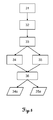
- fig. 5
- illustrates a method for generating scaled terrain information with an unmanned autonomous gardening vehicle according to the invention by a flowchart.
-
Fig. 1 shows an unmanned autonomous gardening vehicle according to the invention being implemented as an unmannedautonomous lawnmower 1 comprising a set of twodrive wheels 5, aguiding wheel 6, amower tool 7 and acamera 10. Thedrive wheels 5 are arranged at opposite sides (left and right) at the back of thelawnmower 1 concerning a driving direction according to the shown arrow A. Thedrive wheels 5 are driven in separate manner as to provide directing of thelawnmower 1 according to respective rotation rates of thewheels 5. Particularly, two motors are provided - each being connected to one of the drive wheels - for controlled movement of the lawnmower as to the rotation rates of thewheels 5. - According to an alternative embodiment of the invention (not shown), at least one of the
wheels 5 is driven by a motor and directing thelawnmower 1 is realised by turning theguiding wheel 6 towards a designated directions. - The
mower tool 7 comprises a set of cutting blades (at least one), wherein themower tool 7 is rotatable around an axis B and thereby cutting plants by the rotating cutting blade. The position of themower tool 7 is variable as to its distance to the ground or the bottom side of thelawnmower 1, respectively. - Moreover, the
camera 10 is attached at the front of thelawnmower 1 for capturing images of the terrain (environment) while movement of themower 1 over ground (generating a set of image data). Thecamera 10 provides to capture a series of images of the terrain, wherein the rate for capturing the images (frames per second) is chosen so that two (successive) images cover an amount of identical points in the terrain, i.e. the frame rate particularly is adjustable depending on the velocity of thelawnmower 1. - As the position (and orientation) of the
mower 1 is continuously changing while mowing and the position (and orientation) of thecamera 10 is changing as well, each captured image covers an alternative terrain section. The captured terrain section thus is defined by the respective pose and the viewing area of thecamera 10. - SLAM (simultaneous localisation and mapping) is performed based on the series of (successive) images by execution of a respective algorithm on a processing unit. The processing unit may be located at the
lawnmower 1 or may be embodied as a remote unit receiving data (via wireless communication) from the lawnmower and providing processed data or control signals to themower 1, e.g. the processing unit being integrated to a remote or field controller of themower 1. Terrain data is produced by applying the SLAM algorithm. - In the context of executing the SLAM-algorithm, the spatial representation of the terrain's surface (= terrain data) in form of a point cloud is computed from the set of image data (captured images), e.g. a 3D model. Alternatively and - as the principle of mapping and localisation corresponds to SLAM principle - also lying in the scope of the present invention, this calculation may be done by a defined Structure-from-Motion (SfM) algorithm, wherein that algorithm may be part of a stored program with code. The SLAM- or SfM-algorithm can be based on a perspective or affine camera projection model with observation sources which compromises image pairs, image tuples and/or a video sequence and token types such as sparse feature correspondence, dense optical flow field, lines or curves, or direct SfM-techniques that do not extract any tokens from the images.
- In context with the present invention, SLAM and SfM are to be considered as equivalent methods for generating terrain information.
- As an example, the following algorithm is described, which compromises a step where a number of image correspondences (= identical points in the terrain) are found for at least some of the images of the set of image data. This is done using feature detection and matching algorithms such as SIFT, SURF, BRISK, BRIEF, etc. Alternatively, in case of a video sequence, the correspondences can be found using a tracking algorithm on each video frame. Tracking can be done using e.g. Kanade-Lucas-Tomasi (KLT) feature tracker or another tracking algorithm.
- Using a pair of successive images the relative camera pose, i.e. position and orientation, is determined in a local coordinate frame. The algorithm uses a robust search to find a 3D translation and rotation of the
camera 10 of the pair of images, e.g. the relative position and orientation of the second image with respect to the first image. With these positions the 3D position of all features seen in both images is computed using forward intersection. This gives a set of 3D points and the positions and orientations of the two initial images (frames). - In the next step, additional images (frames) are added to the existing reconstruction. Using already reconstructed 3D points, the position and orientation, which the
camera 10 had during capture of an image, can be computed using resectioning. After adding a new image, the positions of 3D points are refined using all measurements in the reconstructed frames. - Particularly, as a final or intermediate step, the overall solution is refined using bundle adjustment. This part of the algorithm is a non-linear least squares minimization of the re-projection error. It will optimise the location and orientation of all camera positions and all 3D points.
- If the recording contains multiple images from the same location, e.g. when the lawnmower stops moving, these images from the same location are matched. This will increase the overall accuracy.
- Alternatively, other SLAM algorithms can be used to recover the positions and orientations of the
camera 10. To further speed up the process, images can be transferred to a control and evaluation unit during the recording of the data. - In a further development of the method, a further improvement of the spatial representation of the terrain's surface can be achieved by computing a dense point cloud, e.g. a 3D-coordinate for each image pixel, with an algorithm such as dense matching algorithm, e.g. depth map fusion or plane sweeping.
- In a next step, the point cloud and particularly the position data for the mower, particularly for each of the captured terrain sections (spatial representation of the terrain), is scaled with help of information about a known absolute reference. Advantageously, both a vertical and a horizontal orientation of the terrain data are determined using a known vertical reference.
- According to specific embodiment of the invention, such scaling of the terrain data is enabled by capturing and processing of an image of a reference body of known shape and/or structure, particularly an elongated reference body, that defines e.g. a long axis due to its elongated shape and comprises at least two defined visually detectable markings, whereby at least two points are defined on the reference body. The reference body may be designed as for example a scale bar or a bar with two or more optical markers in a defined distance to each other.
- An absolute distance in between the at least two points, particularly also the spatial relationship of the at least two points with respect to the long axis of the body, are known. This reference body is placed on or next to the terrain to be mown. The reference body is imaged with help of the
camera 10 on at least some images together with or additionally to the captured terrain images. At least two spatial positions relative to the terrain are determined for the at least two points for instance also based on the SLAM-evaluation. Then, the point cloud is scaled based on a measured distance in between the determined at least two spatial positions and the known absolute distance in between the at least two points of the reference body. - Such a reference body can also be formed by defined points or objects in the terrain with known distance, detectable in an image. This known distance can be derived by a measurement with a measurement device such as a distance meter (electronic distance meter, EDM), which can be integrated in the lawnmower e.g. in form of a DISTO module (compare
fig. 2 ). Such a visually detectable point can be defined by an edge or a spot with a different property compared to the surrounding. A visually detectable point can further comprise an optical marking such as a colour spot or a geometric shape like a circle. As an example, a reference body can thus be formed by an object of known dimensions, such as the height or width of the object or of a part of it. - According to another specific embodiment of the invention, the absolute scale information is derived by measuring the propagation of the
lawnmower 1 while generating the set of image data, i.e. while moving. - For that purpose, the
lawnmower 1 comprises a measuring unit for detecting the rotation or state of rotation of at least onewheel mower 1, in particular of the at least onedrive wheel 5. Such a unit may be embodied as a counting sensor which counts the number of rotations of thewheel wheel lawnmower 1. Such a unit may specifically be designed as angle encoder. Moreover, the dimensions of therespective wheel lawnmower 1 is enabled to be derived based on the detection of the wheel rotation and the dimensions of thewheel lawnmower 1 in the terrain is provided. - The images captured by the camera or respective terrain sections are associated to the correspondingly measured moving distances. By that, the terrain data (point cloud), which is based on the captured images, is scaleable by comparing measured distances to the derived point cloud and/or to the position data relating to positions of the lawnmower. In a further step, a scaled map of the terrain is processable.
- Therefore, according to each of the alternatives for providing the absolute scale, an efficient method for gathering scaled terrain information and simultaneously generating a map of the terrain is given. Thus, the
lawnmower 1 can be places in unknown terrain, wherein by execution of the SLAM based on images, which are captured while moving themower 1 in the terrain, a navigation of themower 1 is enabled. -
Fig. 2 shows a further embodiment according to the present invention. The lawnmower 1 (which represents a gardening vehicle according to the invention) again comprises a set ofdrive wheels 5, aguiding wheel 6 and acutting tool 7. Moreover, twocameras mower 1 for capturing images of theterrain 20, i.e. particularly of theground 21 and e.g. of bushes and/ortrees 22. Thecameras mower 1. That design of camera attachment allows to align acamera - At least one of the
cameras - Additionally, the
lawnmower 1 comprises an electronicdistance measuring unit 12 for determining a distance to an object, e.g. to atree 22, by emitting alaser beam 13 and receiving the reflected beam. Distances may be derived based on measuring the travel time (time of flight) of an emitted laser light pulse till receiving the respective reflected light pulse at theunit 12. Alternatively, respective distances are derived based on other known principles. Such anelectronic distance meter 12 is particularly designed as laser DISTO module (as particularly offered by Leica Geosystems AG). - According to the invention, the scaling of terrain information, which is enabled to be derived by SLAM on basis of the captured images of the
terrain 20 while moving thelawnmower 1, is done by associating the terrain information with distance information from the electronicdistance measuring unit 12. For that, distances to a designated object in theterrain 20, e.g. to a specified (reflecting) body, to a building or to a plant, are determined with defined time interval, in particular continuously, by the electronicdistance measuring unit 12. According to a specific embodiment of the invention, the determination of a distance value to the object is provided for each captured image, in particular wherein distance measuring and image capturing are synchronised. Thus, an absolute distance between two reference points of respective captured images and a scaling for the images and for a terrain map, which bases on the images, is provided. Furthermore, a derived point cloud and/or position data may be scaled by help of the measured distances. - Particularly, the electronic
distance measuring unit 12 is attached to thelawnmower 1 so that theunit 12 and thelaser beam 13 are swivelable about two axes. Such a design enables to keep aiming onto one designated point in the terrain while moving themower 1 and continuously gathering position information for themower 1 regarding that point (by distance measurements). For keep aiming onto such a fixed point, themower 1 may comprise further sensor units which allow to determine the orientation of themower 1 e.g. relative to a gravitation vector (e.g. inclination sensor and/or acceleration sensor) and to align the electronicdistance measuring unit 12 for keep aiming the point based on the determined orientation. -
Fig. 3 shows another specific embodiment of an unmanned autonomous gardening vehicle according to the invention, again represented by arespective lawnmower 1, wherein themower 1 is basically designed as already shown infigs. 1 and2 . As a difference to the previously described embodiments, themower 1 comprises acamera 10c being attached to a supporting unit which provides motorised alignment of thecamera 10c relative to thelawnmower 1 about two axes. Thus, the field of view of thecamera 10c is alignable in any direction for aiming a designated point in the environment. Accordingly, the alignment of the camera can be adapted during movement of themower 1 for instance in order to keep a defined object in the field of view. - Furthermore, the
mower 1 comprises anobservation unit 11. Thatunit 11 is integrated in the housing oflawnmower 11 as shown here, but may - according to alternative embodiments (not shown) - be e.g. located on top of the housing of thelawnmower 11. Theobservation unit 11 comprises a further camera and a distance determination functionality, in particular wherein the further camera comprises the distance determination functionality and is built e.g. as RIM-camera (range image camera). Such RIM-camera provides both image information according to a captured field of view and range information for each of a defined amount of pixels of a captured image, wherein the range information typically provides distances to respective objects (or parts thereof) in the image. The RIM-camera may be built so that a measurement of time of flight of a controlled light pulse is provided for each pixel (or a defined group of pixels) of the camera's sensor. - According to a further specific embodiment of the invention, the
mower 1 only comprises theobservation unit 11 with a camera but without having an additional camera 10-10c. - Similar to the scaling procedure as described with
fig. 2 , a respective scaling of the terrain information here is performed by use of the rage information from theobservation unit 11. Distances to an object are (continuously) determined by help of the distance determination functionality and, thus, an absolute measure of a moving distance for thelawnmower 1 is derived. - The absolute measure is linked with respective relative positions of points, which are to be defined for the captured images (e.g. automatically by a specified algorithm or by the SLAM-algorithm), and the scaling of the derived point cloud and of e.g. a created map (with position data relating to the position of the mower) is applied based on that linkage.
- Moreover, range information delivered by the distance determination functionality particularly may be processed by the SLAM algorithm and provides a more precise determination of the terrain information.
-
Fig. 4 shows aterrain 20 to be autonomously mown by anunmanned lawnmower 1 according to the invention. The area of theterrain 20 is limited by afence 25, ahedge 26 and asmall river 24. Furthermore, theterrain 20 comprises twotrees 22, which represent obstacles with respect to the work of themower 1. - According to the invention, the
lawnmower 1 comprises functionality for determining a borderline 15 for theterrain 20 to be mown, wherein that borderline 15 limits the area of movement for themower 1. For such border determination themower 1 is moved along the border of theterrain 20, e.g. by manually controlling themower 1, whereby images of the border region are captured by the camera of themower 1 and stored in a storage unit for providing reference image data representing the border region. Arespective borderline 15 is derived from that data (e.g. by image processing). The borderline 15 may be represented by particular coordinates (derived by SLAM and scaling) which are associated to the image data, particularly to respectively captured images. - A controlling of the
mower 1 for autonomous movement inside theterrain 1 then is based on the reference image data, wherein currently captured images are compared to the reference data and based on that comparison a state of approach to the borderline 15 is determined. Themower 1 is controlled so that an approach to the borderline 15 up to a defined distance is allowed. If themower 1 moves to close to the line 15 a controlling command is provided for steering themower 1 in an alternative direction (e.g. in a reverse direction). Particularly the mower is stopped if it crosses the borderline 15. - Alternatively, the borderline 15 is derived while autonomous movement of the
mower 1 in theterrain 20, wherein the captured images are provided to an image processing unit and terrain borders are derived based on the image processing, particularly by feature extraction based on predefined structures or pattern which represent terrain border structures (e.g. a fence). The borderline 15 as well is derived by image processing. For instance, if themower 1 gets near thehedge 26 or thefence 25 and takes corresponding images of these structures, such images are supplied to image processing and compared to reference patterns, which schematically represent a fence and/or hedge. Additionally, a reference pattern or colour structure representing water is provided for enabling the detection of water, especially of thesmall river 24. - According to the invention, respective border information is linked with absolute position information derived by the SLAM algorithm and by scaling the derived terrain information. Thus, an absolute position of the borderline 15 in the terrain is known.
- A further aspect of the invention relates to position referenced detection of specific or current state of at least a part of the terrain. For that, captured images are processed in order to derive a state parameter, which represents the actual state of a terrain section, the state particularly relating to a condition (i.e. health) of at least one plant and/or of the ground.
- For assessing respective terrain sections with view to their state, respective state parameters for the terrain sections are to be compared to predefined reference parameters, particularly to respective thresholds for the state parameters. Based on that comparison, i.e. depending on if a parameter exceeds a threshold, respective state information concerning the terrain section may be generated.
- Such state information is provided to a user of the system as gardener information. The gardener information may comprise the positions of the terrain section, a relative measure concerning the deviation of the state of the terrain section from threshold and/or an advice for the user regarding how to treat the terrain section in order to improve its current condition.
- Particularly, the gardener information - as well as any other information produced by the
lawnmower 1 or received by the lawnmower 1 - may be transmitted to the user via a wireless communication link, e.g. via radio, Bluetooth, WiFi or mobile phone communication standard (e.g. GSM). For instance, the information is received and processed by a smart phone. - According to a specific embodiment of the invention, the parameter to be checked if a respective terrain section exceeds a defined threshold, provides at least one terrain factor of a group of terrain factors, the group comprising the following factors
- plant height, particularly grass length,
- plant growth, particularly of a bush or a hedge,
- humidity of the terrain,
- density of plants, e.g. of grass stalks,
- planarity of the terrain and
- brightness or colour of the terrain.
- According to a specific embodiment of the
lawnmower 1 of the invention, themower 1 comprises additional tools for treating terrain, ground and/or plants. Such tools may be applied depending on the gardener information and/or on a command of the user. In case a respective treatment of the terrain section is to be performed, the mower is enabled - according to the mapping of the terrain - to move to the respective terrain section and to apply a designated tool. In that context, the lawnmower e.g. comprises a gardener tool, the gardener tool particularly being designed as fertilising unit, watering unit or lawn thatcher. - According to a further embodiment of the invention, the
lawnmower 1 comprises functionality for detecting obstacles (here: trees 22) in theterrain 20 to be mown. Such detection is provided by image processing of images captured by the camera of themower 1. Furthermore, a determination of a position of therespective obstacle 22 can be done by use of the SLAM algorithm and scaling of the terrain data. - According to yet another embodiment of the invention (not shown here), a docking station is provided in the
terrain 20 in order to recharge the battery of themower 1. If the charging level of the battery comes under a defined limit, themower 1 is controlled to move to the docking station, particularly on a direct path, based on the gathered terrain data (e.g. map of the terrain). The docking station may comprise a cleaning unit which provides cleaning of the camera of themower 1 in a docking state. -
Fig. 5 illustrates a method for generating scaled terrain information, i.e. a scaled point cloud of the terrain, with an unmanned autonomous gardening vehicle (e.g. lawnmower) according to the invention. - First, the gardening vehicle is located at an arbitrary point in unknown terrain or environment (step 31). According to a specific embodiment, the gardening vehicle may be located in an already known terrain.
- For gathering the terrain information, the gardening vehicle is moving (e.g. according to a random path or according to a redefined moving strategy) in the terrain (step 32), whereby it takes images of the terrain (of respective terrain sections corresponding to the poses of the gardening vehicle and its camera and the camera properties).
- The capturing of the images is controlled so that successively captured images would cover at least partly a common sub-region of the terrain (if the vehicle moves linearly without unexpected influences) in order to provide identical points in the terrain in each of the successive images. In that context, a frequency of capturing the images is adaptable depending on the movement of the gardening vehicle, in particular depending on the moving speed and the changes of orientation of the gardening vehicle while moving.
- A method of simultaneous localisation and mapping (SLAM) is applied (step 33) to the captured images in order to derive terrain information. As described above, such SLAM provides both the possibility of localising the gardening vehicle in the terrain and the possibility of (simultaneously) mapping the terrain, particularly by generating a point cloud (e.g. on basis of stereo-photogrammetry provided by the movement of the vehicle) or map or model of the covered terrain and determining the position of the gardening vehicle in that terrain (in the point cloud).
- A possible approach for realising such SLAM is based on the following principle. The gardening vehicle is placed at an arbitrary position in the environment (step 31), that arbitrary position defines an origin of a coordinate system and thus the first (origin) position of the vehicle in that coordinate system is known. Starting at that first known position, the gardening vehicle is moving in the terrain and capturing images of the terrain (step 32). A first image covers a first terrain section, a second image still covers a part of the first terrain section and an additional region of the terrain together representing a second terrain section and a next image covers a part of the second terrain section and a further additional terrain region (and so on).
- By means of the captured (overlapping) images a tracking of the movement of the vehicle is provided by processing the captured images and particularly identifying common positions in the terrain on at least two images, i.e. respective positions of the vehicle are determinable (step 34). Moreover, a map of the terrain (e.g. in form of one big point cloud) is creatable by processing the images so that one cohesive (i.e. continuous) point cloud based on the plurality of captured images is processable (step 35) on basis of identified identical points in the images. Particularly, stereoscopic bases for calculating the point clouds (based on e.g. two successive images) may be provided by the movement of the gardening vehicle and the image capturing frequency.
- Thus, the SLAM process is configured to incrementally generate a map (point cloud) of the terrain and continuously determining current positions of the gardening vehicle while moving.
- The map and the position in the terrain are derived based on above process. However, such process does not provide a scaled map or a measure of relative positions in the terrain as for instance a distance between two positions. The map is based on image data only, wherein the determined positions of the gardening vehicle are derived from the image data as well. The image data does not provide any information about distances in the terrain. Thus, an entire map of the terrain to be treated may be derived, whereby that map initially represents the whole terrain but in an un-scaled manner, i.e. distances between single points of the point cloud are unknown.
- According to the invention, a respective scaling of the point cloud (and particularly of the position data for the gardening vehicle) is performed by applying absolute scale information (e.g. a measure for distances) to the terrain data (step 36). The absolute scale information is derivable by several methods as described in context of
figs. 1-3 . According to these methods, an absolute measure can be derived e.g. by measuring the rotation of a wheel of the gardening vehicle (wherein the diameter of the wheel is known), by continuously measuring distances to an object in the terrain and determining the changes of distance to that object by a distance measuring unit or RIM-camera and/or by capturing and processing images of defined markers in the terrain. - As a result of the scaling
step 36scaled terrain data - Such scaled data allows generating a map of the terrain with a precise measure and to exactly determine and provide a current position of the gardening vehicle. Additionally, the scaled terrain data enables to improve planning of movement of the gardening vehicle in the terrain for more efficiently covering the entire terrain area, i.e. reducing the distance travelled by the gardening vehicle until each terrain section was reached and treated or planning travelled distances in dependency of a state of charge of the battery of the gardening vehicle.
- Above described methods for gathering information with a gardening vehicle and/or navigation of a gardening vehicle are analogously applicable by an autonomously working vacuum cleaner known from the prior art.
Claims (15)
- Method for generating scaled terrain information with an unmanned autonomous gardening vehicle (1), the gardening vehicle (1) comprising• a driving unit comprising□ a set of at least one drive wheel (5) and□ a motor connected to the at least one drive wheel (5) for providing movability of the gardening vehicle (1),• a gardening-tool (7) and• a camera (10-10c) for capturing images of a terrain (20), the camera (10-10c) being positioned and aligned in known manner relative to the gardening vehicle (1),wherein the method comprises• moving the gardening vehicle (1) in the terrain (20) whilst concurrently generating a set of image data by capturing an image series of terrain sections so that at least two images, particularly successive images, of the image series cover an amount of identical points in the terrain (20), wherein the terrain sections are defined by a viewing area of the camera (10-10c) at respective positions of the camera (10-10c) while moving,• applying a simultaneous localisation and mapping (SLAM) algorithm to the set of image data and thereby deriving terrain data, the terrain data comprising□ a point cloud representing the captured terrain (20) and□ position data relating to a relative position of the gardening vehicle (1) in the terrain (20), and• scaling the point cloud by applying an absolute scale information to the terrain data, particularly scaling the position data.
- Method according to claim 1,
characterised in that
the unmanned autonomous gardening vehicle (1) is implemented as an unmanned autonomous lawnmower (1), particularly wherein the gardening-tool (7) is implemented as a cutting-tool (7). - Method according to claim 1 or 2,
characterised in that
the absolute scale information is derived by receiving movement data from a sensor unit of the gardening vehicle (1) providing information about a distance covered by moving the gardening vehicle (1), the sensor unit being designed as• a sensor for detecting revolutions of a wheel (5,6) of the gardening vehicle (1), particularly the at least one drive wheel (5), and/or• a distance measuring unit (12), particularly DISTO-module, for measuring distances to an object (22) by emitting laser light (13) and receiving the laser light reflected at the object (22) and/or• a range camera, particularly RIM camera, and/or• an inertial measuring unit (IMU). - Method according to any on of claims 1 to 3,
characterised in that
the absolute scale information is derived by capturing a reference image of a reference body of known appearance and/or position in the terrain (20) and deriving the absolute scale information by image processing based on the appearance of the reference body in the captured reference image and particularly of a known magnification ratio of the camera (10-10c), particularly wherein the dimensions, spatial orientation and/or shape of the reference body is pre-known. - Method according to any one of claims 1 to 4,
characterised by
transmitting the set of image data and/or the terrain data to a database and storing the data in it, wherein• the gardening vehicle (1) comprises a storing unit comprising the database, and/or• a remote controlling unit for controlling the gardening vehicle (1) comprises the storing unit comprising the database, and/or• the database is embodied by a data cloud, particularly stored on a remote server, particularly wherein the terrain data is derived from the image data by cloud computing based on the simultaneous localisation and mapping (SLAM) algorithm and/or the scaling of the point cloud is performed by cloud computing. - Method according to any one of claims 1 to 5,
characterised in that
a borderline (15) of a working area for the gardening vehicle (1), within which the gardening vehicle (1) is controllable to autonomously move and work, is defined by• teaching the borderline (15) by□ moving the gardening vehicle (1) along a desired path,□ capturing a series of border-images of terrain corresponding to the path and of a defined vicinity relative to the path, the series of border-images represents the image series, and□ providing the series of border-images for controlling the gardening vehicle (1), or• setting the borderline (15) on basis of a terrain map, wherein border-position data is provided for controlling the gardening vehicle (1). - Method according to claim 6,
characterised by
- in case the borderline (15) is defined by teaching -• continuously comparing the border-images of the series of border-images with actual images by image processing, the actual images being captured while moving the gardening vehicle (1) inside the working area,• deriving a rate of matching for every actual image based on the comparison and• controlling the movement of the gardening vehicle (1) based on the rate of matching so that the gardening vehicle (1) automatically moves only inside the working area, particularly providing a movement-controlling command for adapting the movement direction of the gardening vehicle (1) if the rate of matching exceeds a predetermined matching-threshold. - Method according to any one of claims 1 to 7,
characterised by• extracting at least one state parameter from the set of image data and/or from the terrain data which represents an actual state of at least one designated terrain section, the state particularly relating to a state of at least one plant and/or of ground,• comparing the state parameter to a predetermined threshold for the respective state and• deriving gardener information based on the comparison of the predetermined threshold and the state parameter,in particular wherein the state parameter provides at least one terrain factor of a group of terrain factors, the group of terrain factors comprising at least the following factors• plant height, particularly grass length,• plant growth, particularly of bush or hedge,• humidity of the terrain,• density of plants,• planarity of the terrain and• brightness or colour of the terrain. - Method according to claim 8,
characterised in that• the gardener information is provided to a user of the gardening vehicle (1), particularly together with a related recommendation concerning a suggested treatment of the respective at least one designated terrain section, and/or• the gardening-tool (7) is applied based on the gardener information, the gardening-tool (7) particularly being designed as cutting-tool (7), particularly hedge-cutter, tree-branch cutter, grass-cutter or scissors, fertilising unit, pesticide unit, watering unit or lawn thatcher. - Method according to any one of claims 1 to 9,
characterised by
applying the gardening-tool (7) based on the terrain data, in particular based on the point cloud, wherein• the terrain data represents at least an actual shape of an object (22,26) in the captured terrain (20),• gardening data is provided representing a target shape for the object (22,26) and• the gardening-tool (7) is guided based on the gardening data so that the actual shape of the object (22,26) is transferred into the target shape, in particular wherein the gardening vehicle (1) is positioned at a designated position in the terrain (20) based on the terrain data and the gardening-tool (7) is guided according to a designated shape of a plant (22,26) based on the terrain data and the gardening data. - Method according to any one of claims 1 to 10,
characterised by• providing controlling information for controlling a further gardening unit in the terrain (20), wherein the controlling information is derived by the terrain data and an actual position and orientation of the further gardening unit in the terrain (20), wherein the position and orientation of the gardening unit is derived from the terrain data by data processing or by image processing of an image covering at least a part of the gardening unit and particularly a part of the terrain (20), in particular wherein the gardening unit comprises a 6DoF-target providing the determination of the orientation of the gardening unit with six degrees of freedom by image processing, and/or• creating a digital terrain map, particularly a digital terrain model, based on the point cloud, particularly based on the terrain data. - Unmanned autonomous gardening vehicle (1) comprising• a driving unit comprising□ a set of at least one drive wheel (5) and□ a motor connected to the at least one drive wheel (5) for providing movability of the gardening vehicle (1),• a gardening-tool (7),• a camera (10-10c) for capturing images of a terrain (20), the camera (10-10c) being positioned and aligned in known manner relative to the gardening vehicle (1),and• a controlling unit for controlling the gardening vehicle (1),characterised in that
the gardening vehicle (1) providing a functionality adapted to generate scaled terrain information by executing, respectively controlling, following steps• moving the gardening vehicle (1) in the terrain (20) whilst concurrently generating a set of image data by capturing an image series of terrain sections so that at least two images, particularly successive images, of the image series cover an amount of identical points in the terrain (20), wherein the terrain sections are defined by a viewing area of the camera (10-10c) at respective positions of the camera (10-10c) while moving,• applying a simultaneous localisation and mapping (SLAM) algorithm to the set of image data and thereby deriving terrain data, the terrain data comprising□ a point cloud representing the captured terrain (20) and□ position data relating to a relative position of the gardening vehicle (1) in the terrain (20), and• scaling the point cloud by applying an absolute scale information to the terrain data, particularly scaling the position data. - Unmanned autonomous gardening vehicle (1) according to claim 12,
characterised in that
the unmanned autonomous gardening vehicle (1) is implemented as an unmanned autonomous lawnmower (1), particularly wherein the gardening-tool (7) is implemented as a cutting-tool (7). - Unmanned autonomous gardening vehicle (1) according to claim 12 or 13,
characterised in that• the gardening vehicle (1) being designed so that a method according to any one of claims 1 to 11 is executable by the gardening vehicle (1), particularly wherein the gardening vehicle (1) comprises a processing unit and the execution of the method being provided by the controlling and processing units, and/or• the gardening vehicle (1) comprising□ a counting sensor counting the number of revolutions of a wheel (5,6) of the gardening vehicle (1), particularly of the at least one drive wheel (5), the counting sensor providing the absolute scale information and/or□ a distance measuring unit (12), particularly DISTO-module, for measuring distances to an object (22) by emitting laser light (13) and receiving the laser light reflected at the object (22) and/or□ a range camera, particularly RIM camera, and/or□ swivelling means for swivelling the camera (10-10c) so that the camera (10-10c) is alignable in a desired direction for capturing the terrain sections or a reference body which provides the absolute scale information. - Computer programme product having computer-executable instructions for controlling and executing a method of one of the claims 1 to 11, in particular when run on a controlling unit, and particularly on a processing unit, of an unmanned autonomous gardening vehicle (1) according to any one of the claims 12 to 14.
Priority Applications (3)
| Application Number | Priority Date | Filing Date | Title |
|---|---|---|---|
| EP13196892.7A EP2884364B1 (en) | 2013-12-12 | 2013-12-12 | Autonomous gardening vehicle with camera |
| CN201410858241.XA CN104714547B (en) | 2013-12-12 | 2014-11-27 | Autonomous gardens vehicle with camera |
| US14/563,815 US9603300B2 (en) | 2013-12-12 | 2014-12-08 | Autonomous gardening vehicle with camera |
Applications Claiming Priority (1)
| Application Number | Priority Date | Filing Date | Title |
|---|---|---|---|
| EP13196892.7A EP2884364B1 (en) | 2013-12-12 | 2013-12-12 | Autonomous gardening vehicle with camera |
Publications (2)
| Publication Number | Publication Date |
|---|---|
| EP2884364A1 true EP2884364A1 (en) | 2015-06-17 |
| EP2884364B1 EP2884364B1 (en) | 2018-09-26 |
Family
ID=49882796
Family Applications (1)
| Application Number | Title | Priority Date | Filing Date |
|---|---|---|---|
| EP13196892.7A Active EP2884364B1 (en) | 2013-12-12 | 2013-12-12 | Autonomous gardening vehicle with camera |
Country Status (3)
| Country | Link |
|---|---|
| US (1) | US9603300B2 (en) |
| EP (1) | EP2884364B1 (en) |
| CN (1) | CN104714547B (en) |
Cited By (38)
| Publication number | Priority date | Publication date | Assignee | Title |
|---|---|---|---|---|
| WO2017085132A1 (en) * | 2015-11-17 | 2017-05-26 | Sidis Engineering Aps | Robotic agricultural vehicle with safety measures |
| US9946263B2 (en) | 2013-12-19 | 2018-04-17 | Aktiebolaget Electrolux | Prioritizing cleaning areas |
| CN108244680A (en) * | 2018-01-17 | 2018-07-06 | 苏州亮磊知识产权运营有限公司 | A kind of self contained multipurpose animal feeding-stuff production equipment and its method of work |
| US10045675B2 (en) | 2013-12-19 | 2018-08-14 | Aktiebolaget Electrolux | Robotic vacuum cleaner with side brush moving in spiral pattern |
| US10149589B2 (en) | 2013-12-19 | 2018-12-11 | Aktiebolaget Electrolux | Sensing climb of obstacle of a robotic cleaning device |
| KR20190008460A (en) * | 2017-07-13 | 2019-01-24 | 한국에너지기술연구원 | Movable sensing apparatus , and system for managing cultivation facility using the same |
| US10209080B2 (en) | 2013-12-19 | 2019-02-19 | Aktiebolaget Electrolux | Robotic cleaning device |
| US10219665B2 (en) | 2013-04-15 | 2019-03-05 | Aktiebolaget Electrolux | Robotic vacuum cleaner with protruding sidebrush |
| WO2019040997A1 (en) * | 2017-09-04 | 2019-03-07 | Commonwealth Scientific And Industrial Research Organisation | Method and system for use in performing localisation |
| US10231591B2 (en) | 2013-12-20 | 2019-03-19 | Aktiebolaget Electrolux | Dust container |
| WO2019067206A1 (en) * | 2017-09-28 | 2019-04-04 | Uber Technologies, Inc. | Sensor control system for autonomous vehicle |
| CN109782771A (en) * | 2019-02-26 | 2019-05-21 | 西安交通大学 | A kind of orchard mobile robot and edge of a field forward method |
| US10433697B2 (en) | 2013-12-19 | 2019-10-08 | Aktiebolaget Electrolux | Adaptive speed control of rotating side brush |
| US10448794B2 (en) | 2013-04-15 | 2019-10-22 | Aktiebolaget Electrolux | Robotic vacuum cleaner |
| US10499778B2 (en) | 2014-09-08 | 2019-12-10 | Aktiebolaget Electrolux | Robotic vacuum cleaner |
| US10518416B2 (en) | 2014-07-10 | 2019-12-31 | Aktiebolaget Electrolux | Method for detecting a measurement error in a robotic cleaning device |
| US10534367B2 (en) | 2014-12-16 | 2020-01-14 | Aktiebolaget Electrolux | Experience-based roadmap for a robotic cleaning device |
| EP3613270A1 (en) * | 2018-08-24 | 2020-02-26 | Ningbo NGP Industry Co., Ltd. | Intelligent mower based on lidar map building |
| CN110956651A (en) * | 2019-12-16 | 2020-04-03 | 哈尔滨工业大学 | Terrain semantic perception method based on fusion of vision and vibrotactile sense |
| US10617271B2 (en) | 2013-12-19 | 2020-04-14 | Aktiebolaget Electrolux | Robotic cleaning device and method for landmark recognition |
| WO2020033504A3 (en) * | 2018-08-08 | 2020-05-14 | The Toro Company | Autonomous machine navigation and training using vision system |
| US10678251B2 (en) | 2014-12-16 | 2020-06-09 | Aktiebolaget Electrolux | Cleaning method for a robotic cleaning device |
| US10729297B2 (en) | 2014-09-08 | 2020-08-04 | Aktiebolaget Electrolux | Robotic vacuum cleaner |
| US10874271B2 (en) | 2014-12-12 | 2020-12-29 | Aktiebolaget Electrolux | Side brush and robotic cleaner |
| US10877484B2 (en) | 2014-12-10 | 2020-12-29 | Aktiebolaget Electrolux | Using laser sensor for floor type detection |
| CN112740888A (en) * | 2019-10-31 | 2021-05-04 | 安德烈·斯蒂尔股份两合公司 | Method for teaching at least one section of a ground boundary for a green space cultivation system, method for operating a green space cultivation system, teaching system |
| EP3324727B1 (en) | 2015-07-24 | 2021-08-18 | iRobot Corporation | Controlling robotic lawnmowers |
| US11099554B2 (en) | 2015-04-17 | 2021-08-24 | Aktiebolaget Electrolux | Robotic cleaning device and a method of controlling the robotic cleaning device |
| US11122953B2 (en) | 2016-05-11 | 2021-09-21 | Aktiebolaget Electrolux | Robotic cleaning device |
| US11145143B2 (en) | 2017-01-31 | 2021-10-12 | Honda Motor Co., Ltd. | Unmanned work system, management server, and unmanned work machine |
| SE544259C2 (en) * | 2018-06-07 | 2022-03-15 | Husqvarna Ab | Robotic work tool system and method for defining a working area |
| US20220174865A1 (en) * | 2020-12-04 | 2022-06-09 | Scythe Robotics, Inc. | Autonomous lawn mower |
| WO2022195477A1 (en) | 2021-03-15 | 2022-09-22 | The Toadi Order BV | Method for navigation of an unmanned autonomous vehicle, unmanned autonomous vehicle, and i ts use |
| BE1029194A1 (en) | 2021-03-15 | 2022-10-10 | The Toadi Order BV | PROCEDURE FOR NAVIGATION OF AN UNMANNED AUTONOMOUS VEHICLE, UNMANNED AUTONOMOUS VEHICLE AND USE |
| EP4102184A1 (en) * | 2021-06-10 | 2022-12-14 | R-Go Robotics Ltd | Techniques for environmental parameter mapping |
| WO2023280533A1 (en) * | 2021-07-07 | 2023-01-12 | Positec Power Tools (Suzhou) Co., Ltd | Method and apparatus for controlling self-moving device |
| WO2023238081A1 (en) | 2022-06-09 | 2023-12-14 | Eeve Bv | Method for determining a work zone for an unmanned autonomous vehicle |
| EP4316232A1 (en) * | 2022-08-04 | 2024-02-07 | Suzhou Cleva Precision Machinery & Technology Co., Ltd. | Mowing device |
Families Citing this family (60)
| Publication number | Priority date | Publication date | Assignee | Title |
|---|---|---|---|---|
| US8798840B2 (en) * | 2011-09-30 | 2014-08-05 | Irobot Corporation | Adaptive mapping with spatial summaries of sensor data |
| KR101779962B1 (en) * | 2013-10-31 | 2017-09-20 | 한국전자통신연구원 | Steering control apparatus for comprising will decision of drivers and method for operating the same |
| WO2015119263A1 (en) * | 2014-02-06 | 2015-08-13 | ヤンマー株式会社 | Method for setting travel path of autonomous travel work vehicle |
| US10324461B2 (en) * | 2014-07-30 | 2019-06-18 | Yanmar Co., Ltd. | Remote control apparatus |
| US10609862B2 (en) | 2014-09-23 | 2020-04-07 | Positec Technology (China) Co., Ltd. | Self-moving robot |
| WO2016103068A1 (en) * | 2014-12-22 | 2016-06-30 | Husqvarna Ab | Robotic vehicle grass structure detection |
| SE539760C2 (en) * | 2014-12-23 | 2017-11-21 | Husqvarna Ab | Control of downhill movement for a robotic work tool |
| EP3081068B1 (en) * | 2015-04-17 | 2021-06-09 | Honda Research Institute Europe GmbH | Autonomous lawn mower, module for an autonomous lawn mower and system comprising such autonomous lawn mower and module |
| CN105123090A (en) * | 2015-07-16 | 2015-12-09 | 张萍 | Multifunctional intelligent mower based on internet of things |
| US20170054947A1 (en) * | 2015-08-19 | 2017-02-23 | Caterpillar Inc. | System and method for monitoring condition of worksite |
| EP3156873B2 (en) * | 2015-10-15 | 2023-04-05 | Honda Research Institute Europe GmbH | Autonomous vehicle with improved simultaneous localization and mapping function |
| DE102015222414A1 (en) * | 2015-11-13 | 2017-05-18 | Robert Bosch Gmbh | Autonomous working device |
| US10705528B2 (en) * | 2015-12-15 | 2020-07-07 | Qualcomm Incorporated | Autonomous visual navigation |
| US10217207B2 (en) | 2016-01-20 | 2019-02-26 | Ez3D, Llc | System and method for structural inspection and construction estimation using an unmanned aerial vehicle |
| EP3413090A4 (en) * | 2016-02-06 | 2019-10-16 | Positec Power Tools (Suzhou) Co., Ltd | Automatic operating system, self-moving device and control method thereof |
| CN105557672A (en) * | 2016-02-16 | 2016-05-11 | 江苏省农业科学院 | Fruit tree target detection system |
| AU2016398122B2 (en) * | 2016-03-17 | 2019-07-04 | Honda Motor Co., Ltd. | Unmanned Operation Vehicle |
| US10206323B2 (en) * | 2016-03-29 | 2019-02-19 | Memes Associates, Ltd | Plant by plant harvester |
| US10234856B2 (en) * | 2016-05-12 | 2019-03-19 | Caterpillar Inc. | System and method for controlling a machine |
| US10448555B2 (en) | 2016-05-27 | 2019-10-22 | Cnh Industrial America Llc | System and method for scouting vehicle mapping |
| DE102016109919A1 (en) * | 2016-05-30 | 2017-11-30 | Carl Zeiss Ag | Device for measuring objects |
| WO2018000922A1 (en) | 2016-06-30 | 2018-01-04 | Tti (Macao Commercial Offshore) Limited | An autonomous lawn mower and a system for navigating thereof |
| US11172608B2 (en) | 2016-06-30 | 2021-11-16 | Tti (Macao Commercial Offshore) Limited | Autonomous lawn mower and a system for navigating thereof |
| AU2019200410B2 (en) * | 2016-06-30 | 2021-01-28 | Tti (Macao Commercial Offshore) Limited | An autonomous lawn mower and a system for navigating thereof |
| US11172607B2 (en) | 2016-06-30 | 2021-11-16 | Tti (Macao Commercial Offshore) Limited | Autonomous lawn mower and a system for navigating thereof |
| CN106272562A (en) * | 2016-08-31 | 2017-01-04 | 贺宜 | A kind of machine vision and the fitting method of robot |
| DE102016120196A1 (en) * | 2016-10-24 | 2018-04-26 | Deutsches Zentrum für Luft- und Raumfahrt e.V. | Method and device for automatically determining position and / or movement-related status information of a vehicle |
| JP6681326B2 (en) * | 2016-12-27 | 2020-04-15 | 本田技研工業株式会社 | Work system and work method |
| JP6687511B2 (en) * | 2016-12-28 | 2020-04-22 | 本田技研工業株式会社 | Control device, monitoring device, and control program |
| JP6635910B2 (en) * | 2016-12-28 | 2020-01-29 | 本田技研工業株式会社 | Information processing device, water supply system, information processing system and program |
| JP6726094B2 (en) * | 2016-12-28 | 2020-07-22 | 本田技研工業株式会社 | Control device, work machine and program |
| US9989835B1 (en) | 2017-02-09 | 2018-06-05 | Cnh Industrial America Llc | System and method for mounting a camera on a work vehicle |
| JP6815479B2 (en) * | 2017-03-03 | 2021-01-20 | 本田技研工業株式会社 | Display control device, display control method and storage medium |
| US11582903B1 (en) | 2017-05-17 | 2023-02-21 | Hydro-Gear Limited Partnership | Vision based guidance system and method for lawn mowing devices |
| EP3424304B1 (en) * | 2017-07-04 | 2021-05-26 | Andreas Stihl AG & Co. KG | Garden and/or forest system for wireless determination of distances |
| DE102017116661A1 (en) * | 2017-07-24 | 2019-01-24 | Vorwerk & Co. Interholding Gmbh | System for recording three-dimensional environmental data, in particular for plant care and sensor module |
| DE102017116658A1 (en) | 2017-07-24 | 2019-01-24 | Vorwerk & Co. Interholding Gmbh | Automatically movable device with a monitoring module outdoors |
| WO2019125807A1 (en) * | 2017-12-21 | 2019-06-27 | Basf Corporation | Autonomous vehicle for the detection and control of plant diseases |
| CN110347144B (en) * | 2018-04-03 | 2023-06-09 | 苏州宝时得电动工具有限公司 | Self-mobile device, self-learning method thereof and readable storage medium |
| WO2019241923A1 (en) * | 2018-06-20 | 2019-12-26 | Lingdong Technology (Beijing) Co., Ltd | Unmanned lawn mower with autonomous driving |
| SE544055C2 (en) * | 2018-06-26 | 2021-11-23 | Husqvarna Ab | A method for collision detection in a self-propelled robotic tool and a self-propelled robotic tool |
| US11350564B1 (en) | 2018-06-28 | 2022-06-07 | Hydro-Gear Limited Partnership | Vision system integration |
| CN109141364B (en) * | 2018-08-01 | 2020-11-03 | 北京进化者机器人科技有限公司 | Obstacle detection method and system and robot |
| JP2020047188A (en) * | 2018-09-21 | 2020-03-26 | パナソニックIpマネジメント株式会社 | Autonomous traveling cleaner |
| CN109566057B (en) * | 2018-12-06 | 2021-05-04 | 新昌县澄聚农业科技有限公司 | Back-push type lawn trimming mechanism |
| GB2580690B (en) * | 2019-01-24 | 2023-03-29 | Imperial College Innovations Ltd | Mapping an environment using a state of a robotic device |
| US11464161B1 (en) | 2019-03-29 | 2022-10-11 | Hydro-Gear Limited Partnership | Automatic sensitivity adjustment for an autonomous mower |
| US11457558B1 (en) | 2019-05-15 | 2022-10-04 | Hydro-Gear Limited Partnership | Autonomous vehicle navigation |
| CN110245445B (en) * | 2019-06-21 | 2020-04-07 | 浙江城建规划设计院有限公司 | Ecological garden landscape design method based on computer three-dimensional scene simulation |
| KR102328399B1 (en) * | 2019-07-10 | 2021-11-18 | 엘지전자 주식회사 | Lawn mower robot and control method the same |
| JP7410150B2 (en) * | 2019-07-23 | 2024-01-09 | 本田技研工業株式会社 | Autonomous work equipment, control method and program for autonomous work equipment |
| JP7462642B2 (en) * | 2019-07-23 | 2024-04-05 | 本田技研工業株式会社 | Autonomous work machine, control device, control method for autonomous work machine, operation method of control device, and program |
| CN112540600A (en) * | 2019-09-19 | 2021-03-23 | 苏州宝时得电动工具有限公司 | Boundary correction method for working area of self-moving equipment and self-moving equipment |
| CN113068501A (en) * | 2020-01-06 | 2021-07-06 | 苏州宝时得电动工具有限公司 | Intelligent mower |
| US20210364632A1 (en) * | 2020-05-24 | 2021-11-25 | Havenshine Technologies, Inc. | Methods and Systems for Map Creation and Calibration of Localization Equipment in an Outdoor Environment |
| US20220184801A1 (en) * | 2020-12-14 | 2022-06-16 | Honda Research Institute Europe Gmbh | Controlling an autonomous working device based on physical interaction |
| CN112925310B (en) * | 2021-01-22 | 2023-08-08 | 广州大学 | Control method, device, equipment and storage medium of intelligent deinsectization system |
| US11805726B1 (en) | 2021-04-20 | 2023-11-07 | Ss Turf Technologies, Llc | Autonomous robotic system and method for fostering controlled growth of a target C4 turf grass area |
| WO2023023142A1 (en) * | 2021-08-18 | 2023-02-23 | Firefly Automatix, Inc. | Determining orientation of a mower using horizon mapping |
| CN115843528A (en) * | 2021-09-24 | 2023-03-28 | 苏州宝时得电动工具有限公司 | Gardening tool system and working method thereof |
Citations (3)
| Publication number | Priority date | Publication date | Assignee | Title |
|---|---|---|---|---|
| WO2004059900A2 (en) * | 2002-12-17 | 2004-07-15 | Evolution Robotics, Inc. | Systems and methods for visual simultaneous localization and mapping |
| WO2007051972A1 (en) | 2005-10-31 | 2007-05-10 | Qinetiq Limited | Navigation system |
| EP2620050A1 (en) * | 2012-01-25 | 2013-07-31 | Honda Research Institute Europe GmbH | System, method and apparatus for unsupervised adaptation of the perception of an autonomous mower |
Family Cites Families (26)
| Publication number | Priority date | Publication date | Assignee | Title |
|---|---|---|---|---|
| US8788092B2 (en) * | 2000-01-24 | 2014-07-22 | Irobot Corporation | Obstacle following sensor scheme for a mobile robot |
| US6832000B2 (en) * | 2001-03-28 | 2004-12-14 | Koninklijke Philips Electronics N.V. | Automatic segmentation-based grass detection for real-time video |
| US8396592B2 (en) * | 2001-06-12 | 2013-03-12 | Irobot Corporation | Method and system for multi-mode coverage for an autonomous robot |
| US6728608B2 (en) * | 2002-08-23 | 2004-04-27 | Applied Perception, Inc. | System and method for the creation of a terrain density model |
| US7362439B2 (en) * | 2003-08-01 | 2008-04-22 | Li-Cor, Inc. | Method of detecting the condition of a turf grass |
| US7542624B1 (en) * | 2005-06-08 | 2009-06-02 | Sandia Corporation | Window-based method for approximating the Hausdorff in three-dimensional range imagery |
| DE112009000094T5 (en) * | 2008-01-04 | 2010-11-11 | 3M Innovative Properties Co., St. Paul | Refinement of three-dimensional models |
| US9104202B2 (en) * | 2010-05-11 | 2015-08-11 | Irobot Corporation | Remote vehicle missions and systems for supporting remote vehicle missions |
| US8918209B2 (en) * | 2010-05-20 | 2014-12-23 | Irobot Corporation | Mobile human interface robot |
| US20110295636A1 (en) * | 2010-05-27 | 2011-12-01 | Noel Wayne Anderson | Autonomous machine selective consultation |
| TWI431250B (en) * | 2011-03-01 | 2014-03-21 | Navigation device for integrated traffic image recording and navigation information | |
| US8958911B2 (en) * | 2012-02-29 | 2015-02-17 | Irobot Corporation | Mobile robot |
| US20130271579A1 (en) * | 2012-04-14 | 2013-10-17 | Younian Wang | Mobile Stereo Device: Stereo Imaging, Measurement and 3D Scene Reconstruction with Mobile Devices such as Tablet Computers and Smart Phones |
| CN102771246B (en) * | 2012-07-05 | 2014-12-10 | 芜湖鸿宇智能科技有限公司 | Intelligent mower system and intelligent mowing method thereof |
| DE102012211961A1 (en) * | 2012-07-10 | 2014-01-30 | Robert Bosch Gmbh | Method and apparatus for calculating a change in a magnification of an object |
| US8831290B2 (en) * | 2012-08-01 | 2014-09-09 | Mitsubishi Electric Research Laboratories, Inc. | Method and system for determining poses of vehicle-mounted cameras for in-road obstacle detection |
| JP5963353B2 (en) * | 2012-08-09 | 2016-08-03 | 株式会社トプコン | Optical data processing apparatus, optical data processing system, optical data processing method, and optical data processing program |
| US9497901B2 (en) * | 2012-08-14 | 2016-11-22 | Husqvarna Ab | Boundary definition system for a robotic vehicle |
| US9466143B1 (en) * | 2013-05-03 | 2016-10-11 | Exelis, Inc. | Geoaccurate three-dimensional reconstruction via image-based geometry |
| EP2804151B1 (en) * | 2013-05-16 | 2020-01-08 | Hexagon Technology Center GmbH | Method for rendering data of a three-dimensional surface |
| CA2920251A1 (en) * | 2013-08-02 | 2015-02-05 | Xactware Solutions, Inc. | System and method for detecting features in aerial images using disparity mapping and segmentation techniques |
| CN105658167B (en) * | 2013-08-23 | 2018-05-04 | 斯瑞克欧洲控股I公司 | Computer for being determined to the coordinate conversion for surgical navigational realizes technology |
| US20150219767A1 (en) * | 2014-02-03 | 2015-08-06 | Board Of Regents, The University Of Texas System | System and method for using global navigation satellite system (gnss) navigation and visual navigation to recover absolute position and attitude without any prior association of visual features with known coordinates |
| EP3034995B1 (en) * | 2014-12-19 | 2024-02-28 | Leica Geosystems AG | Method for determining a position and orientation offset of a geodetic surveying device and corresponding measuring device |
| WO2016172125A1 (en) * | 2015-04-19 | 2016-10-27 | Pelican Imaging Corporation | Multi-baseline camera array system architectures for depth augmentation in vr/ar applications |
| EP3086196B1 (en) * | 2015-04-21 | 2017-04-05 | Hexagon Technology Center GmbH | Method and control system for surveying and mapping a terrain while operating a bulldozer |
-
2013
- 2013-12-12 EP EP13196892.7A patent/EP2884364B1/en active Active
-
2014
- 2014-11-27 CN CN201410858241.XA patent/CN104714547B/en active Active
- 2014-12-08 US US14/563,815 patent/US9603300B2/en active Active
Patent Citations (3)
| Publication number | Priority date | Publication date | Assignee | Title |
|---|---|---|---|---|
| WO2004059900A2 (en) * | 2002-12-17 | 2004-07-15 | Evolution Robotics, Inc. | Systems and methods for visual simultaneous localization and mapping |
| WO2007051972A1 (en) | 2005-10-31 | 2007-05-10 | Qinetiq Limited | Navigation system |
| EP2620050A1 (en) * | 2012-01-25 | 2013-07-31 | Honda Research Institute Europe GmbH | System, method and apparatus for unsupervised adaptation of the perception of an autonomous mower |
Non-Patent Citations (1)
| Title |
|---|
| YANG JUNHO ET AL: "Vision-based localization and mapping for an autonomous mower", 2013 IEEE/RSJ INTERNATIONAL CONFERENCE ON INTELLIGENT ROBOTS AND SYSTEMS, IEEE, 3 November 2013 (2013-11-03), pages 3655 - 3662, XP032537318, ISSN: 2153-0858, [retrieved on 20131227], DOI: 10.1109/IROS.2013.6696878 * |
Cited By (51)
| Publication number | Priority date | Publication date | Assignee | Title |
|---|---|---|---|---|
| US10219665B2 (en) | 2013-04-15 | 2019-03-05 | Aktiebolaget Electrolux | Robotic vacuum cleaner with protruding sidebrush |
| US10448794B2 (en) | 2013-04-15 | 2019-10-22 | Aktiebolaget Electrolux | Robotic vacuum cleaner |
| US10209080B2 (en) | 2013-12-19 | 2019-02-19 | Aktiebolaget Electrolux | Robotic cleaning device |
| US10045675B2 (en) | 2013-12-19 | 2018-08-14 | Aktiebolaget Electrolux | Robotic vacuum cleaner with side brush moving in spiral pattern |
| US10149589B2 (en) | 2013-12-19 | 2018-12-11 | Aktiebolaget Electrolux | Sensing climb of obstacle of a robotic cleaning device |
| EP3084540B1 (en) * | 2013-12-19 | 2021-04-14 | Aktiebolaget Electrolux | Robotic cleaning device and operating method |
| US10617271B2 (en) | 2013-12-19 | 2020-04-14 | Aktiebolaget Electrolux | Robotic cleaning device and method for landmark recognition |
| US10433697B2 (en) | 2013-12-19 | 2019-10-08 | Aktiebolaget Electrolux | Adaptive speed control of rotating side brush |
| US9946263B2 (en) | 2013-12-19 | 2018-04-17 | Aktiebolaget Electrolux | Prioritizing cleaning areas |
| US10231591B2 (en) | 2013-12-20 | 2019-03-19 | Aktiebolaget Electrolux | Dust container |
| US10518416B2 (en) | 2014-07-10 | 2019-12-31 | Aktiebolaget Electrolux | Method for detecting a measurement error in a robotic cleaning device |
| US10499778B2 (en) | 2014-09-08 | 2019-12-10 | Aktiebolaget Electrolux | Robotic vacuum cleaner |
| US10729297B2 (en) | 2014-09-08 | 2020-08-04 | Aktiebolaget Electrolux | Robotic vacuum cleaner |
| US10877484B2 (en) | 2014-12-10 | 2020-12-29 | Aktiebolaget Electrolux | Using laser sensor for floor type detection |
| US10874271B2 (en) | 2014-12-12 | 2020-12-29 | Aktiebolaget Electrolux | Side brush and robotic cleaner |
| US10534367B2 (en) | 2014-12-16 | 2020-01-14 | Aktiebolaget Electrolux | Experience-based roadmap for a robotic cleaning device |
| US10678251B2 (en) | 2014-12-16 | 2020-06-09 | Aktiebolaget Electrolux | Cleaning method for a robotic cleaning device |
| US11099554B2 (en) | 2015-04-17 | 2021-08-24 | Aktiebolaget Electrolux | Robotic cleaning device and a method of controlling the robotic cleaning device |
| EP3324727B1 (en) | 2015-07-24 | 2021-08-18 | iRobot Corporation | Controlling robotic lawnmowers |
| EP3639644A1 (en) * | 2015-11-17 | 2020-04-22 | VEKTOR Dynamics ApS | Robotic agricultural vehicle with safety measures |
| WO2017085132A1 (en) * | 2015-11-17 | 2017-05-26 | Sidis Engineering Aps | Robotic agricultural vehicle with safety measures |
| US11122953B2 (en) | 2016-05-11 | 2021-09-21 | Aktiebolaget Electrolux | Robotic cleaning device |
| EP3579155B1 (en) * | 2017-01-31 | 2021-11-17 | Honda Motor Co., Ltd. | Unmanned work system, management server, and unmanned work machine |
| US11145143B2 (en) | 2017-01-31 | 2021-10-12 | Honda Motor Co., Ltd. | Unmanned work system, management server, and unmanned work machine |
| KR20190008460A (en) * | 2017-07-13 | 2019-01-24 | 한국에너지기술연구원 | Movable sensing apparatus , and system for managing cultivation facility using the same |
| US11402509B2 (en) | 2017-09-04 | 2022-08-02 | Commonwealth Scientific And Industrial Research Organisation | Method and system for use in performing localisation |
| WO2019040997A1 (en) * | 2017-09-04 | 2019-03-07 | Commonwealth Scientific And Industrial Research Organisation | Method and system for use in performing localisation |
| US10843669B2 (en) | 2017-09-28 | 2020-11-24 | Uatc, Llc | Sensor control system for autonomous vehicle |
| WO2019067206A1 (en) * | 2017-09-28 | 2019-04-04 | Uber Technologies, Inc. | Sensor control system for autonomous vehicle |
| CN108244680A (en) * | 2018-01-17 | 2018-07-06 | 苏州亮磊知识产权运营有限公司 | A kind of self contained multipurpose animal feeding-stuff production equipment and its method of work |
| SE544259C2 (en) * | 2018-06-07 | 2022-03-15 | Husqvarna Ab | Robotic work tool system and method for defining a working area |
| WO2020033504A3 (en) * | 2018-08-08 | 2020-05-14 | The Toro Company | Autonomous machine navigation and training using vision system |
| EP3613270A1 (en) * | 2018-08-24 | 2020-02-26 | Ningbo NGP Industry Co., Ltd. | Intelligent mower based on lidar map building |
| CN109782771A (en) * | 2019-02-26 | 2019-05-21 | 西安交通大学 | A kind of orchard mobile robot and edge of a field forward method |
| US11758839B2 (en) * | 2019-10-31 | 2023-09-19 | Andreas Stihl Ag & Co. Kg | Method for teaching at least one section of a delimiting border of a land area for a green area maintenance system, method for operating a green area maintenance system, teach-in system and green area maintenance system |
| US20210127569A1 (en) * | 2019-10-31 | 2021-05-06 | Andreas Stihl Ag & Co. Kg | Method for Teaching At Least One Section of a Delimiting Border of a Land Area for a Green Area Maintenance System, Method for Operating a Green Area Maintenance System, Teach-In System and Green Area Maintenance System |
| CN112740888A (en) * | 2019-10-31 | 2021-05-04 | 安德烈·斯蒂尔股份两合公司 | Method for teaching at least one section of a ground boundary for a green space cultivation system, method for operating a green space cultivation system, teaching system |
| CN112740888B (en) * | 2019-10-31 | 2024-04-09 | 安德烈·斯蒂尔股份两合公司 | Method for teaching at least one section of a ground boundary for a greenfield cultivation system, method for operating a greenfield cultivation system, teaching system |
| CN110956651B (en) * | 2019-12-16 | 2021-02-19 | 哈尔滨工业大学 | Terrain semantic perception method based on fusion of vision and vibrotactile sense |
| CN110956651A (en) * | 2019-12-16 | 2020-04-03 | 哈尔滨工业大学 | Terrain semantic perception method based on fusion of vision and vibrotactile sense |
| US20220174865A1 (en) * | 2020-12-04 | 2022-06-09 | Scythe Robotics, Inc. | Autonomous lawn mower |
| BE1029194B1 (en) * | 2021-03-15 | 2022-10-17 | The Toadi Order BV | PROCEDURE FOR NAVIGATION OF AN UNMANNED AUTONOMOUS VEHICLE, UNMANNED AUTONOMOUS VEHICLE AND USE |
| DE202022100588U1 (en) | 2021-03-15 | 2022-10-19 | The Toadi Order BV | Unmanned, autonomous vehicle |
| BE1029194A1 (en) | 2021-03-15 | 2022-10-10 | The Toadi Order BV | PROCEDURE FOR NAVIGATION OF AN UNMANNED AUTONOMOUS VEHICLE, UNMANNED AUTONOMOUS VEHICLE AND USE |
| WO2022195477A1 (en) | 2021-03-15 | 2022-09-22 | The Toadi Order BV | Method for navigation of an unmanned autonomous vehicle, unmanned autonomous vehicle, and i ts use |
| EP4102184A1 (en) * | 2021-06-10 | 2022-12-14 | R-Go Robotics Ltd | Techniques for environmental parameter mapping |
| US11886188B2 (en) | 2021-06-10 | 2024-01-30 | R-Go Robotics, Ltd. | Techniques for environmental parameter mapping |
| WO2023280533A1 (en) * | 2021-07-07 | 2023-01-12 | Positec Power Tools (Suzhou) Co., Ltd | Method and apparatus for controlling self-moving device |
| WO2023238081A1 (en) | 2022-06-09 | 2023-12-14 | Eeve Bv | Method for determining a work zone for an unmanned autonomous vehicle |
| BE1030604A1 (en) | 2022-06-09 | 2024-01-11 | Eeve Bv | METHOD FOR DETERMINING A WORK ZONE FOR AN UNMANNED AUTONOMOUS VEHICLE |
| EP4316232A1 (en) * | 2022-08-04 | 2024-02-07 | Suzhou Cleva Precision Machinery & Technology Co., Ltd. | Mowing device |
Also Published As
| Publication number | Publication date |
|---|---|
| CN104714547B (en) | 2018-03-27 |
| EP2884364B1 (en) | 2018-09-26 |
| CN104714547A (en) | 2015-06-17 |
| US9603300B2 (en) | 2017-03-28 |
| US20150163993A1 (en) | 2015-06-18 |
Similar Documents
| Publication | Publication Date | Title |
|---|---|---|
| US9603300B2 (en) | Autonomous gardening vehicle with camera | |
| CN112584697B (en) | Autonomous machine navigation and training using vision system | |
| US11845189B2 (en) | Domestic robotic system and method | |
| CN109033948B (en) | Method for identifying at least one section of boundary edge and related method and system | |
| US20230236604A1 (en) | Autonomous machine navigation using reflections from subsurface objects | |
| EP4066076B1 (en) | Autonomous machine navigation in various lighting environments | |
| US20230069475A1 (en) | Autonomous machine navigation with object detection and 3d point cloud | |
| US11981336B2 (en) | Vehicle row follow system | |
| EP4368004A1 (en) | Improved operation and installation for a robotic work tool | |
| US20230094371A1 (en) | Vehicle row follow system | |
| US20240155973A1 (en) | Operation and installation for a robotic work tool | |
| US20210378171A1 (en) | Control interface for autonomy | |
| CA3160530A1 (en) | Autonomous machine navigation in various lighting environments | |
| Urcola et al. | On-line trajectory planning for autonomous spraying vehicles | |
| Rovira-Más | Stereoscopic Vision for Off-Road Intelligent Vehicles |
Legal Events
| Date | Code | Title | Description |
|---|---|---|---|
| PUAI | Public reference made under article 153(3) epc to a published international application that has entered the european phase |
Free format text: ORIGINAL CODE: 0009012 |
|
| 17P | Request for examination filed |
Effective date: 20131212 |
|
| AK | Designated contracting states |
Kind code of ref document: A1 Designated state(s): AL AT BE BG CH CY CZ DE DK EE ES FI FR GB GR HR HU IE IS IT LI LT LU LV MC MK MT NL NO PL PT RO RS SE SI SK SM TR |
|
| AX | Request for extension of the european patent |
Extension state: BA ME |
|
| RIN1 | Information on inventor provided before grant (corrected) |
Inventor name: PETTERSSON, BO |
|
| R17P | Request for examination filed (corrected) |
Effective date: 20151211 |
|
| RBV | Designated contracting states (corrected) |
Designated state(s): AL AT BE BG CH CY CZ DE DK EE ES FI FR GB GR HR HU IE IS IT LI LT LU LV MC MK MT NL NO PL PT RO RS SE SI SK SM TR |
|
| STAA | Information on the status of an ep patent application or granted ep patent |
Free format text: STATUS: EXAMINATION IS IN PROGRESS |
|
| 17Q | First examination report despatched |
Effective date: 20170406 |
|
| GRAP | Despatch of communication of intention to grant a patent |
Free format text: ORIGINAL CODE: EPIDOSNIGR1 |
|
| STAA | Information on the status of an ep patent application or granted ep patent |
Free format text: STATUS: GRANT OF PATENT IS INTENDED |
|
| RIC1 | Information provided on ipc code assigned before grant |
Ipc: A01D 34/00 20060101ALI20180417BHEP Ipc: G05D 1/02 20060101AFI20180417BHEP Ipc: A01G 25/09 20060101ALI20180417BHEP |
|
| INTG | Intention to grant announced |
Effective date: 20180508 |
|
| GRAS | Grant fee paid |
Free format text: ORIGINAL CODE: EPIDOSNIGR3 |
|
| GRAA | (expected) grant |
Free format text: ORIGINAL CODE: 0009210 |
|
| STAA | Information on the status of an ep patent application or granted ep patent |
Free format text: STATUS: THE PATENT HAS BEEN GRANTED |
|
| AK | Designated contracting states |
Kind code of ref document: B1 Designated state(s): AL AT BE BG CH CY CZ DE DK EE ES FI FR GB GR HR HU IE IS IT LI LT LU LV MC MK MT NL NO PL PT RO RS SE SI SK SM TR |
|
| REG | Reference to a national code |
Ref country code: GB Ref legal event code: FG4D |
|
| REG | Reference to a national code |
Ref country code: CH Ref legal event code: EP |
|
| REG | Reference to a national code |
Ref country code: AT Ref legal event code: REF Ref document number: 1046769 Country of ref document: AT Kind code of ref document: T Effective date: 20181015 |
|
| REG | Reference to a national code |
Ref country code: IE Ref legal event code: FG4D |
|
| REG | Reference to a national code |
Ref country code: DE Ref legal event code: R096 Ref document number: 602013044133 Country of ref document: DE |
|
| REG | Reference to a national code |
Ref country code: CH Ref legal event code: NV Representative=s name: KAMINSKI HARMANN PATENTANWAELTE AG, LI |
|
| REG | Reference to a national code |
Ref country code: NL Ref legal event code: FP |
|
| PG25 | Lapsed in a contracting state [announced via postgrant information from national office to epo] |
Ref country code: LT Free format text: LAPSE BECAUSE OF FAILURE TO SUBMIT A TRANSLATION OF THE DESCRIPTION OR TO PAY THE FEE WITHIN THE PRESCRIBED TIME-LIMIT Effective date: 20180926 Ref country code: BG Free format text: LAPSE BECAUSE OF FAILURE TO SUBMIT A TRANSLATION OF THE DESCRIPTION OR TO PAY THE FEE WITHIN THE PRESCRIBED TIME-LIMIT Effective date: 20181226 Ref country code: SE Free format text: LAPSE BECAUSE OF FAILURE TO SUBMIT A TRANSLATION OF THE DESCRIPTION OR TO PAY THE FEE WITHIN THE PRESCRIBED TIME-LIMIT Effective date: 20180926 Ref country code: GR Free format text: LAPSE BECAUSE OF FAILURE TO SUBMIT A TRANSLATION OF THE DESCRIPTION OR TO PAY THE FEE WITHIN THE PRESCRIBED TIME-LIMIT Effective date: 20181227 Ref country code: NO Free format text: LAPSE BECAUSE OF FAILURE TO SUBMIT A TRANSLATION OF THE DESCRIPTION OR TO PAY THE FEE WITHIN THE PRESCRIBED TIME-LIMIT Effective date: 20181226 Ref country code: RS Free format text: LAPSE BECAUSE OF FAILURE TO SUBMIT A TRANSLATION OF THE DESCRIPTION OR TO PAY THE FEE WITHIN THE PRESCRIBED TIME-LIMIT Effective date: 20180926 Ref country code: FI Free format text: LAPSE BECAUSE OF FAILURE TO SUBMIT A TRANSLATION OF THE DESCRIPTION OR TO PAY THE FEE WITHIN THE PRESCRIBED TIME-LIMIT Effective date: 20180926 |
|
| REG | Reference to a national code |
Ref country code: SE Ref legal event code: TRGR |
|
| REG | Reference to a national code |
Ref country code: LT Ref legal event code: MG4D |
|
| PG25 | Lapsed in a contracting state [announced via postgrant information from national office to epo] |
Ref country code: AL Free format text: LAPSE BECAUSE OF FAILURE TO SUBMIT A TRANSLATION OF THE DESCRIPTION OR TO PAY THE FEE WITHIN THE PRESCRIBED TIME-LIMIT Effective date: 20180926 Ref country code: LV Free format text: LAPSE BECAUSE OF FAILURE TO SUBMIT A TRANSLATION OF THE DESCRIPTION OR TO PAY THE FEE WITHIN THE PRESCRIBED TIME-LIMIT Effective date: 20180926 Ref country code: HR Free format text: LAPSE BECAUSE OF FAILURE TO SUBMIT A TRANSLATION OF THE DESCRIPTION OR TO PAY THE FEE WITHIN THE PRESCRIBED TIME-LIMIT Effective date: 20180926 |
|
| REG | Reference to a national code |
Ref country code: AT Ref legal event code: MK05 Ref document number: 1046769 Country of ref document: AT Kind code of ref document: T Effective date: 20180926 |
|
| PG25 | Lapsed in a contracting state [announced via postgrant information from national office to epo] |
Ref country code: AT Free format text: LAPSE BECAUSE OF FAILURE TO SUBMIT A TRANSLATION OF THE DESCRIPTION OR TO PAY THE FEE WITHIN THE PRESCRIBED TIME-LIMIT Effective date: 20180926 Ref country code: EE Free format text: LAPSE BECAUSE OF FAILURE TO SUBMIT A TRANSLATION OF THE DESCRIPTION OR TO PAY THE FEE WITHIN THE PRESCRIBED TIME-LIMIT Effective date: 20180926 Ref country code: IT Free format text: LAPSE BECAUSE OF FAILURE TO SUBMIT A TRANSLATION OF THE DESCRIPTION OR TO PAY THE FEE WITHIN THE PRESCRIBED TIME-LIMIT Effective date: 20180926 Ref country code: RO Free format text: LAPSE BECAUSE OF FAILURE TO SUBMIT A TRANSLATION OF THE DESCRIPTION OR TO PAY THE FEE WITHIN THE PRESCRIBED TIME-LIMIT Effective date: 20180926 Ref country code: PL Free format text: LAPSE BECAUSE OF FAILURE TO SUBMIT A TRANSLATION OF THE DESCRIPTION OR TO PAY THE FEE WITHIN THE PRESCRIBED TIME-LIMIT Effective date: 20180926 Ref country code: IS Free format text: LAPSE BECAUSE OF FAILURE TO SUBMIT A TRANSLATION OF THE DESCRIPTION OR TO PAY THE FEE WITHIN THE PRESCRIBED TIME-LIMIT Effective date: 20190126 Ref country code: ES Free format text: LAPSE BECAUSE OF FAILURE TO SUBMIT A TRANSLATION OF THE DESCRIPTION OR TO PAY THE FEE WITHIN THE PRESCRIBED TIME-LIMIT Effective date: 20180926 Ref country code: CZ Free format text: LAPSE BECAUSE OF FAILURE TO SUBMIT A TRANSLATION OF THE DESCRIPTION OR TO PAY THE FEE WITHIN THE PRESCRIBED TIME-LIMIT Effective date: 20180926 |
|
| PG25 | Lapsed in a contracting state [announced via postgrant information from national office to epo] |
Ref country code: PT Free format text: LAPSE BECAUSE OF FAILURE TO SUBMIT A TRANSLATION OF THE DESCRIPTION OR TO PAY THE FEE WITHIN THE PRESCRIBED TIME-LIMIT Effective date: 20190126 Ref country code: SK Free format text: LAPSE BECAUSE OF FAILURE TO SUBMIT A TRANSLATION OF THE DESCRIPTION OR TO PAY THE FEE WITHIN THE PRESCRIBED TIME-LIMIT Effective date: 20180926 Ref country code: SM Free format text: LAPSE BECAUSE OF FAILURE TO SUBMIT A TRANSLATION OF THE DESCRIPTION OR TO PAY THE FEE WITHIN THE PRESCRIBED TIME-LIMIT Effective date: 20180926 |
|
| REG | Reference to a national code |
Ref country code: DE Ref legal event code: R097 Ref document number: 602013044133 Country of ref document: DE |
|
| PG25 | Lapsed in a contracting state [announced via postgrant information from national office to epo] |
Ref country code: DK Free format text: LAPSE BECAUSE OF FAILURE TO SUBMIT A TRANSLATION OF THE DESCRIPTION OR TO PAY THE FEE WITHIN THE PRESCRIBED TIME-LIMIT Effective date: 20180926 |
|
| PLBE | No opposition filed within time limit |
Free format text: ORIGINAL CODE: 0009261 |
|
| STAA | Information on the status of an ep patent application or granted ep patent |
Free format text: STATUS: NO OPPOSITION FILED WITHIN TIME LIMIT |
|
| PG25 | Lapsed in a contracting state [announced via postgrant information from national office to epo] |
Ref country code: LU Free format text: LAPSE BECAUSE OF NON-PAYMENT OF DUE FEES Effective date: 20181212 Ref country code: MC Free format text: LAPSE BECAUSE OF FAILURE TO SUBMIT A TRANSLATION OF THE DESCRIPTION OR TO PAY THE FEE WITHIN THE PRESCRIBED TIME-LIMIT Effective date: 20180926 |
|
| 26N | No opposition filed |
Effective date: 20190627 |
|
| REG | Reference to a national code |
Ref country code: IE Ref legal event code: MM4A |
|
| REG | Reference to a national code |
Ref country code: BE Ref legal event code: MM Effective date: 20181231 |
|
| PG25 | Lapsed in a contracting state [announced via postgrant information from national office to epo] |
Ref country code: IE Free format text: LAPSE BECAUSE OF NON-PAYMENT OF DUE FEES Effective date: 20181212 Ref country code: SI Free format text: LAPSE BECAUSE OF FAILURE TO SUBMIT A TRANSLATION OF THE DESCRIPTION OR TO PAY THE FEE WITHIN THE PRESCRIBED TIME-LIMIT Effective date: 20180926 |
|
| PG25 | Lapsed in a contracting state [announced via postgrant information from national office to epo] |
Ref country code: BE Free format text: LAPSE BECAUSE OF NON-PAYMENT OF DUE FEES Effective date: 20181231 |
|
| PG25 | Lapsed in a contracting state [announced via postgrant information from national office to epo] |
Ref country code: MT Free format text: LAPSE BECAUSE OF NON-PAYMENT OF DUE FEES Effective date: 20181212 |
|
| PGFP | Annual fee paid to national office [announced via postgrant information from national office to epo] |
Ref country code: NL Payment date: 20191219 Year of fee payment: 7 Ref country code: SE Payment date: 20191219 Year of fee payment: 7 |
|
| PG25 | Lapsed in a contracting state [announced via postgrant information from national office to epo] |
Ref country code: TR Free format text: LAPSE BECAUSE OF FAILURE TO SUBMIT A TRANSLATION OF THE DESCRIPTION OR TO PAY THE FEE WITHIN THE PRESCRIBED TIME-LIMIT Effective date: 20180926 |
|
| PGFP | Annual fee paid to national office [announced via postgrant information from national office to epo] |
Ref country code: CH Payment date: 20191219 Year of fee payment: 7 |
|
| PG25 | Lapsed in a contracting state [announced via postgrant information from national office to epo] |
Ref country code: HU Free format text: LAPSE BECAUSE OF FAILURE TO SUBMIT A TRANSLATION OF THE DESCRIPTION OR TO PAY THE FEE WITHIN THE PRESCRIBED TIME-LIMIT; INVALID AB INITIO Effective date: 20131212 Ref country code: MK Free format text: LAPSE BECAUSE OF NON-PAYMENT OF DUE FEES Effective date: 20180926 Ref country code: CY Free format text: LAPSE BECAUSE OF FAILURE TO SUBMIT A TRANSLATION OF THE DESCRIPTION OR TO PAY THE FEE WITHIN THE PRESCRIBED TIME-LIMIT Effective date: 20180926 |
|
| REG | Reference to a national code |
Ref country code: CH Ref legal event code: PL |
|
| REG | Reference to a national code |
Ref country code: SE Ref legal event code: EUG |
|
| REG | Reference to a national code |
Ref country code: NL Ref legal event code: MM Effective date: 20210101 |
|
| PG25 | Lapsed in a contracting state [announced via postgrant information from national office to epo] |
Ref country code: NL Free format text: LAPSE BECAUSE OF NON-PAYMENT OF DUE FEES Effective date: 20210101 |
|
| PG25 | Lapsed in a contracting state [announced via postgrant information from national office to epo] |
Ref country code: CH Free format text: LAPSE BECAUSE OF NON-PAYMENT OF DUE FEES Effective date: 20201231 Ref country code: LI Free format text: LAPSE BECAUSE OF NON-PAYMENT OF DUE FEES Effective date: 20201231 Ref country code: SE Free format text: LAPSE BECAUSE OF FAILURE TO SUBMIT A TRANSLATION OF THE DESCRIPTION OR TO PAY THE FEE WITHIN THE PRESCRIBED TIME-LIMIT Effective date: 20201213 |
|
| REG | Reference to a national code |
Ref country code: DE Ref legal event code: R079 Ref document number: 602013044133 Country of ref document: DE Free format text: PREVIOUS MAIN CLASS: G05D0001020000 Ipc: G05D0001430000 |
|
| PGFP | Annual fee paid to national office [announced via postgrant information from national office to epo] |
Ref country code: GB Payment date: 20231220 Year of fee payment: 11 |
|
| PGFP | Annual fee paid to national office [announced via postgrant information from national office to epo] |
Ref country code: FR Payment date: 20231221 Year of fee payment: 11 Ref country code: DE Payment date: 20231214 Year of fee payment: 11 |