EP2881896A1 - Near field communication tag based data transfer - Google Patents
Near field communication tag based data transfer Download PDFInfo
- Publication number
- EP2881896A1 EP2881896A1 EP14196560.8A EP14196560A EP2881896A1 EP 2881896 A1 EP2881896 A1 EP 2881896A1 EP 14196560 A EP14196560 A EP 14196560A EP 2881896 A1 EP2881896 A1 EP 2881896A1
- Authority
- EP
- European Patent Office
- Prior art keywords
- mobile telecommunication
- data
- nfc tag
- telecommunication device
- access
- Prior art date
- Legal status (The legal status is an assumption and is not a legal conclusion. Google has not performed a legal analysis and makes no representation as to the accuracy of the status listed.)
- Granted
Links
- 238000004891 communication Methods 0.000 title claims abstract description 84
- 238000012546 transfer Methods 0.000 title description 63
- 238000000034 method Methods 0.000 claims abstract description 65
- 230000004044 response Effects 0.000 claims abstract description 33
- 238000013523 data management Methods 0.000 description 80
- 230000008569 process Effects 0.000 description 13
- 238000010586 diagram Methods 0.000 description 8
- 238000012545 processing Methods 0.000 description 5
- 230000003213 activating effect Effects 0.000 description 4
- 230000004913 activation Effects 0.000 description 3
- 230000008901 benefit Effects 0.000 description 3
- 238000005516 engineering process Methods 0.000 description 3
- 230000005540 biological transmission Effects 0.000 description 2
- 230000008859 change Effects 0.000 description 2
- 238000013500 data storage Methods 0.000 description 2
- 238000004519 manufacturing process Methods 0.000 description 2
- 238000012986 modification Methods 0.000 description 2
- 230000004048 modification Effects 0.000 description 2
- 230000003068 static effect Effects 0.000 description 2
- PCTMTFRHKVHKIS-BMFZQQSSSA-N (1s,3r,4e,6e,8e,10e,12e,14e,16e,18s,19r,20r,21s,25r,27r,30r,31r,33s,35r,37s,38r)-3-[(2r,3s,4s,5s,6r)-4-amino-3,5-dihydroxy-6-methyloxan-2-yl]oxy-19,25,27,30,31,33,35,37-octahydroxy-18,20,21-trimethyl-23-oxo-22,39-dioxabicyclo[33.3.1]nonatriaconta-4,6,8,10 Chemical compound C1C=C2C[C@@H](OS(O)(=O)=O)CC[C@]2(C)[C@@H]2[C@@H]1[C@@H]1CC[C@H]([C@H](C)CCCC(C)C)[C@@]1(C)CC2.O[C@H]1[C@@H](N)[C@H](O)[C@@H](C)O[C@H]1O[C@H]1/C=C/C=C/C=C/C=C/C=C/C=C/C=C/[C@H](C)[C@@H](O)[C@@H](C)[C@H](C)OC(=O)C[C@H](O)C[C@H](O)CC[C@@H](O)[C@H](O)C[C@H](O)C[C@](O)(C[C@H](O)[C@H]2C(O)=O)O[C@H]2C1 PCTMTFRHKVHKIS-BMFZQQSSSA-N 0.000 description 1
- 238000013475 authorization Methods 0.000 description 1
- 238000010276 construction Methods 0.000 description 1
- 230000001419 dependent effect Effects 0.000 description 1
- 238000011161 development Methods 0.000 description 1
- 230000010354 integration Effects 0.000 description 1
- 238000007726 management method Methods 0.000 description 1
- 230000003287 optical effect Effects 0.000 description 1
- 230000002093 peripheral effect Effects 0.000 description 1
- 238000004549 pulsed laser deposition Methods 0.000 description 1
- 238000010079 rubber tapping Methods 0.000 description 1
- 238000007790 scraping Methods 0.000 description 1
- 230000001960 triggered effect Effects 0.000 description 1
- 230000000007 visual effect Effects 0.000 description 1
Images


Classifications
-
- H—ELECTRICITY
- H04—ELECTRIC COMMUNICATION TECHNIQUE
- H04B—TRANSMISSION
- H04B5/00—Near-field transmission systems, e.g. inductive or capacitive transmission systems
- H04B5/70—Near-field transmission systems, e.g. inductive or capacitive transmission systems specially adapted for specific purposes
- H04B5/72—Near-field transmission systems, e.g. inductive or capacitive transmission systems specially adapted for specific purposes for local intradevice communication
-
- G—PHYSICS
- G06—COMPUTING; CALCULATING OR COUNTING
- G06K—GRAPHICAL DATA READING; PRESENTATION OF DATA; RECORD CARRIERS; HANDLING RECORD CARRIERS
- G06K19/00—Record carriers for use with machines and with at least a part designed to carry digital markings
- G06K19/06—Record carriers for use with machines and with at least a part designed to carry digital markings characterised by the kind of the digital marking, e.g. shape, nature, code
- G06K19/067—Record carriers with conductive marks, printed circuits or semiconductor circuit elements, e.g. credit or identity cards also with resonating or responding marks without active components
- G06K19/07—Record carriers with conductive marks, printed circuits or semiconductor circuit elements, e.g. credit or identity cards also with resonating or responding marks without active components with integrated circuit chips
-
- G—PHYSICS
- G06—COMPUTING; CALCULATING OR COUNTING
- G06Q—INFORMATION AND COMMUNICATION TECHNOLOGY [ICT] SPECIALLY ADAPTED FOR ADMINISTRATIVE, COMMERCIAL, FINANCIAL, MANAGERIAL OR SUPERVISORY PURPOSES; SYSTEMS OR METHODS SPECIALLY ADAPTED FOR ADMINISTRATIVE, COMMERCIAL, FINANCIAL, MANAGERIAL OR SUPERVISORY PURPOSES, NOT OTHERWISE PROVIDED FOR
- G06Q10/00—Administration; Management
- G06Q10/10—Office automation; Time management
- G06Q10/105—Human resources
-
- G—PHYSICS
- G06—COMPUTING; CALCULATING OR COUNTING
- G06Q—INFORMATION AND COMMUNICATION TECHNOLOGY [ICT] SPECIALLY ADAPTED FOR ADMINISTRATIVE, COMMERCIAL, FINANCIAL, MANAGERIAL OR SUPERVISORY PURPOSES; SYSTEMS OR METHODS SPECIALLY ADAPTED FOR ADMINISTRATIVE, COMMERCIAL, FINANCIAL, MANAGERIAL OR SUPERVISORY PURPOSES, NOT OTHERWISE PROVIDED FOR
- G06Q40/00—Finance; Insurance; Tax strategies; Processing of corporate or income taxes
- G06Q40/12—Accounting
-
- H—ELECTRICITY
- H04—ELECTRIC COMMUNICATION TECHNIQUE
- H04W—WIRELESS COMMUNICATION NETWORKS
- H04W12/00—Security arrangements; Authentication; Protecting privacy or anonymity
- H04W12/06—Authentication
-
- H—ELECTRICITY
- H04—ELECTRIC COMMUNICATION TECHNIQUE
- H04W—WIRELESS COMMUNICATION NETWORKS
- H04W4/00—Services specially adapted for wireless communication networks; Facilities therefor
- H04W4/80—Services using short range communication, e.g. near-field communication [NFC], radio-frequency identification [RFID] or low energy communication
Definitions
- NFC Near field communication
- NFC standards cover communications protocols and data exchange formats, and are based on existing Radio Frequency.
- NFC generally involves a NFC tag.
- the invention relates to a communication method for controlling operation of a near field communication, NFC, tag, wherein the NFC tag is operating in accordance with a first operation mode.
- the method comprises:
- the NFC tag may store locally an amount of data smaller than a predefined threshold e.g. 1% of the total size of the non-volatile memory of the NFC tag.
- a predefined threshold e.g. 1% of the total size of the non-volatile memory of the NFC tag.
- the database system may store data related to the first mobile telecommunication that in amount smaller (e.g. 10% smaller) than the storage size (e.g. volatile and/or non-volatile memory size) of the NFC tag. Storing data locally may be advantageous as it may speed up the data access process compared to the case where data is stored in the database system.
- the first mobile telecommunication device may be an NFC enabled device.
- These features may have the advantage of providing a controlled, optimal and efficient access to data using the NFC tag. These features may provide access to up-to-date dynamic data that may change over time. The change over time may lead to an increase in the amount of the accessed data which then may be stored on the database system if there is not enough space in the NFC tag.
- the determining of the access frequency further comprising: in response to a determination that the number of access of the access frequency is an odd number rejecting the data request ((and leaving the method)).
- This embodiment may provide a secure access to the access information by preventing potential malicious access by suspicious devices.
- mobile telecommunication devices may be controlled to use or contact the NFC tag for logging e.g. to a WiFi network, and another time for logging out. This means that when the first mobile telecommunication device has access the NFC tag e.g. 59 times per month means that in a given day (e.g. the last day of the month) the first mobile telecommunication device has logged in without logging out in the given day which may be an indication of a suspicious act by the first mobile telecommunication device.
- the first mobile telecommunication device is part of a set of mobile telecommunication devices that are authorized to access the NFC tag, wherein the maximum frequency is determined using the number of mobile telecommunication devices of the set of mobile telecommunication devices and a memory size of the NFC tag.
- This embodiment may be advantageous as it may make use of the type of data being stored that is related to access information only for further increasing the access efficiency to the access information.
- the first mobile telecommunication device is part of a set of mobile telecommunication devices that are authorized to access the NFC tag.
- the method further comprises receiving from a second mobile telecommunication device of the set of mobile telecommunication devices via the NFC antenna another data request for providing access information of the second mobile telecommunication device; in response to a determination that an access frequency of the second mobile telecommunication device is equal to the access frequency of the first mobile telecommunication device; sending an identification address of the first mobile telecommunication device to the second mobile telecommunication device in response to the received data request.
- their corresponding access information e.g. the number of access may be the same.
- the second mobile telecommunication device may use the access information sent to the first mobile telecommunication device e.g. by communicating with the first mobile telecommunication device.
- the method further comprises receiving via the NFC antenna from the first mobile telecommunication device a data update in response to receiving the requested data at the first mobile telecommunication device; switching to the second operation mode and forwarding the data update to the database system using the communication link.
- This may for example provide up-to-date access information for subsequent access to the access information of the first mobile telecommunication device.
- the switching step comprising: authenticating the first mobile telecommunication device; and in case the authentication is successful, forwarding the stored data update to the database system.
- This may provide a secure method as the first mobile telecommunication device may only have the read access right but not the write access right. This may control access to data stored in the NFC tag or the database system.
- the method further comprises sending an unlock signal to a data communication unit via the database system for authorizing access of the first telecommunication device to the data communication unit.
- the NFC tag may send the unlock signal to the database system and control the database system to forward the unlock signal to the data communication unit.
- This may have the advantage of making use of a single connection to provide both the access information requested by the first mobile telecommunication device and to allow the first mobile telecommunication device to access the data communication unit. This may save resources that would otherwise be required for running separately the access permission and the data update.
- the method further comprises sending an unlock signal to an automatic door opening and closing system via the database system for enabling (e.g. an automatic door opens) a user of the first mobile telecommunication device to access or enter a building that can only be accessed via the automatic door.
- an unlock signal to an automatic door opening and closing system via the database system for enabling (e.g. an automatic door opens) a user of the first mobile telecommunication device to access or enter a building that can only be accessed via the automatic door.
- the access information comprises at least one of: a number of accesses of the first mobile telecommunication device to the NFC tag; an average access duration per a predefined time period of the first mobile telecommunication device.
- a predetermined minimum frequency rejecting the data request (and leaving the method). This may provide a secure access to the access information as a small access frequency (e.g. 0) may be an indication of a malicious access attempt.
- the NFC tag is connected to the database system via a serial link, wherein establishing the communication link comprises sending a link setup command to the database system via the serial ink for establishing the communication link.
- the NFC tag before the switching to the second operation mode the NFC tag is powered using the NFC antenna, wherein after establishing the communication link the NFC tag is power supplied by the database system via a serial link between the NFC tag and the database system.
- the invention relates to a NFC tag comprising a NFC antenna, the NFC tag operating in a first operation mode, wherein the NFC tag is configured for:
- the invention in another aspect, relates to an access control system comprising a NFC tag, a mobile telecommunication device and a database server according to the previous embodiment.
- the database server may be configured for receiving a data request from the NFC tag and for sending in response to the received data request the access information via the communication link to the NFC tag.
- the mobile telecommunication device is an NFC enabled device.
- the mobile telecommunication device may be configured for sending to the NFC tag a data request for providing access information of the first mobile telecommunication device and fore receiving the access information from the mobile telecommunication device.
- the access control system further comprises a data communication configured for providing a network access to the mobile telecommunication device.
- the invention in another aspect, relates to a computer implemented method for near field communication (NFC) based data transfer.
- the method comprises a NFC tag, receiving dynamic data from a data management system; the NFC tag, forwarding the received dynamic data to a portable electronic device; based on the forwarded dynamic data, the NFC tag receiving data update from the portable electronic device; and forwarding, by the NFC tag, received data update to the data management system.
- NFC near field communication
- the method further comprises the portable electronic device, activating the NFC tag; receiving, at the portable electronic device, the dynamic data for an application stored at the portable electronic device; at the portable electronic device, displaying the received dynamic data; based on the displayed dynamic data, receiving, at the portable electronic device, the data update; and the portable electronic device, forwarding the data update to the NFC tag.
- the method further comprises storing the received data update to the NFC tag.
- the method further comprises based on activating the NFC tag, detecting the stored data update at the portable electronic device; and forwarding the stored data update to the data management system.
- the method further comprises the NFC tag, authenticating the portable electronic device; and based on the authentication, the NFC tag forwarding the stored data update to the data management system.
- the method further comprises the NFC tag, sending a data retrieval request to the data management system; and based on the data retrieval request, the NFC tag receiving the dynamic data from the data management system.
- the method further comprises programming, by a processor of a computer, the NFC tag to transfer data between the portable electronic device and the data management system.
- the invention in another aspect, relates to a computer system for near field communication (NFC) based data transfer.
- the computer system comprises: a processor to execute a program code; and a memory coupled to the processor, the memory storing the program code comprising: receive, by a NFC tag, dynamic data from a data management system; forward, by the NFC tag, the received dynamic data to a portable electronic device; based on the forwarded dynamic data, receive, by the NFC tag, data update from the portable electronic device; and forward received data update to the data management system.
- NFC near field communication
- the invention in another aspect, relates to an article of manufacture including a non-transitory computer readable storage medium to tangibly store instructions, which when executed by a computer, cause the computer to: receive, by a near field communication (NFC) tag, dynamic data from a data management system; forward, by the NFC tag, the received dynamic data to a portable electronic device; based on the forwarded dynamic data, receive, by the NFC tag, data update from the portable electronic device; and forward received data update to the data management system.
- NFC near field communication
- the invention in another aspect, relates to an article of manufacture including a non-transitory computer readable storage medium to tangibly store instructions, which when executed by a computer, cause the computer to: activate a near field communication (NFC) tag by a portable electronic device; send a data retrieval request, by the activated NFC tag, to retrieve dynamic data from a data management system; based on the data retrieval request, receive the dynamic data from the data management system; forward, by the NFC tag, the received dynamic data to the portable electronic device; based on the forwarded dynamic data, receive, by the NFC tag, data update from the portable electronic device; store the received data update to the NFC tag; and forward the received data update to the data management system.
- NFC near field communication
- FIG. 1 is a block diagram illustrating a process 100 for near field communication based data transfer, according to an embodiment.
- NFC Near field communication
- the NFC tag 104 is a passive device, for example, a sticker or a wristband, which includes "data transfer" integrated circuit (IC) 106.
- IC integrated circuit
- the portable electronic device 102 may be a handheld or wearable electronic device, for example, mobile phone, tablet computer, laptop, personal digital assistant, etc.
- the portable electronic device 102 is a NFC enabled portable electronic device that may establish NFC communication with the NFC tag 104.
- the portable electronic device 102 may include data transmitter-receiver module 108 for writing data to the NFC tag 104 and receiving data from the NFC tag 104.
- the NFC tag 104 may be programmed to facilitate data transfer between the portable electronic device 102 and data management system 110.
- the data management system 110 may be a data server that stores and processes data.
- the data management system 110 may be provided in a cloud. Cloud computing addresses a variety of computing concepts that involve a large number of computers connected through a real-time communication network such as the Internet.
- programming the NFC tag 104 may include writing a "data transfer" program to the "data transfer" IC 106 of the NFC tag 104.
- the "data transfer" program defines a sequence of data transfer steps for two-way communication between the portable electronic device 102 and the NFC tag 104.
- the data transfer steps in the "data transfer" program may include: initially sending data retrieval request 112 to the data management system 110.
- the NFC tag 104 may receive 114 data from the data management system 110, in response to the data retrieval request.
- the NFC tag 104 forwards 116 the received data to the portable electronic device 102.
- the portable electronic device 102 may send 118 data update to the NFC tag 104.
- the NFC tag 104 may finally forward 120 the received data update to the data management system 110.
- several applications may use the "data transfer” program, written to the "data transfer” IC 106 of the NFC tag 104.
- the applications may use the "data transfer” program to perform application data transfer between the portable electronic device 102 and the data management system 110, at runtime.
- An application or an “app” is computer software that when executed performs a useful task.
- the applications may also be written to the "data transfer" IC 106 included in the NFC tag 104.
- the applications may be included in the "data transfer” program written to the "data transfer" IC 106 of the NFC tag 104.
- the application may be a stand-alone application written to the "data transfer" IC 106 of the NFC tag 104.
- the NFC tag 104 allows a user of the portable electronic device 102 to access and update application data to the data management system 110, without requiring the user of the portable electronic device 102 to login to the data management system 110.
- the data transfer steps included in the "data transfer" program written to the NFC tag 104 allows application data transfer between the portable electronic device 102 and the data management system 110, without requiring the user to login to the data management system 110.
- the "data transfer" program included in the NFC tag, may facilitate data transfer between the NFC enabled portable electronic device and a data management system that manages information of portable electronic devices, including time spent by the NFC enabled portable electronic device on a particular connection task or session.
- the data transfer steps defined by the "data transfer” program may be used for transferring "time recording" application data between the data management system and the portable electronic device.
- the NFC tag may send a "data retrieval" request for receiving "time recording” data, for example, the "time spent” information that includes information of the time spent by the NFC enabled portable electronic device on different connection sessions.
- the NFC tag receives the "time recording” data that includes, e.g., session names "Alpha” and “Beta", identification address of the NFC enabled portable electronic device "IJKL”, and the time spent as “3 days” and "1 day” for sessions “Alpha” and “Beta”, respectively, from the data management system.
- the NFC tag forwards the "time recording” data to the portable electronic device.
- the NFC enabled portable electronic device may then update (automatically or upon receiving update data e.g. from a user of the portable electronic device) the "time recording" data for session "Beta” from “1 day” to "2 days", at the portable electronic device.
- the updated "time recording” data "2 days” is then forwarded to the NFC tag.
- the NFC tag forwards the updated "time recording” data to the data management system that may be finally updated to the data management system.
- the portable electronic device retrieves "time recording” data from the data management system and updates the "time recording” data to the data management system, using the NFC tag, without connecting to a network or the data management system.
- the NFC tag therefore allows a user to conveniently access and update application data without requiring a login to the data management system.
- the programmed NFC tag 104 can be used by any number of applications that require one-way or two-way communication between the portable electronic device 102 and the data management system 110 to transfer application data.
- the programmed NFC tag 104 may be used by a "leave request" application that requires a one-way communication to push a leave request, from the portable electronic device 102, to the data management system 110, without a user logging to the data management system 110.
- FIGS. 2A-2B are flow diagrams illustrating an algorithm for "data transfer” process 200 written to an NFC tag, according to an embodiment.
- the "data transfer” process 200 may define data transfer steps for transferring data between two devices, for example, a portable electronic device and a data management system.
- the "data transfer” method may be included in a "data transfer” program that is written to a "data transfer” IC included in the NFC tag. After the write operation, the steps included in the "data transfer” method may be used to transfer application data, of an application, between the portable electronic device and the data management system.
- the "data transfer" process 200 includes initially, at 202 ( FIG. 2A ), activating the NFC tag by a portable electronic device.
- NFC tag or a smart tag, may be a passive device that is capable of NFC communication.
- a passive device is a device that does not require a source of energy for its operation.
- the NFC tag may be activated based on the magnetic field induced by a NFC enabled portable electronic device that is in contact or proximity of the NFC tag.
- the NFC tag may be activated by a NFC enabled portable electronic device.
- the NFC tag may be activated for the first time when the NFC enabled portable electronic device is in contact or in proximity of the NFC tag, for the first time.
- authentication information is generated for the portable electronic device of the user, at 206.
- a unique identification key may be generated and linked to user identification information related to the user of the portable electronic device.
- the NFC tag may send a data retrieval request to the data management system.
- the data retrieval request may be sent to retrieve data from the data management system.
- the NFC tag may receive data from the data management system (at 210).
- the data received by the NFC tag is dynamic data.
- Dynamic data denotes data that is asynchronously changed as further updates to the data become available. For example, "number of hours spent" on a project, by a user, is a dynamic data that changes based on the time spent by the user working on the project.
- the NFC tag is programmed to receive and send dynamic data.
- the NFC tag may forward the dynamic data received from the data management system to the portable electronic device.
- data update may be received at the portable electronic device.
- a user of the portable electronic device may want to update the dynamic data received from the NFC tag.
- the user may provide the data update at the portable electronic device.
- the data update may be an updated version of the dynamic data received from the data management system.
- the data update is the most recent version of the dynamic data that the user wants to upload to the data management system. For example, consider that the data received from the data management system is user's leave data that includes the number of leaves the user has applied for in a particular year.
- the user may provide, at the portable electronic device, a leave data update with the correct number of leaves that the user wants to update to the data management system.
- the data update received at the portable electronic device may then be forwarded at 214, to an NFC tag that stores (218) the data update received from the portable electronic device.
- the data update may be stored in the "data transfer" IC included in the NFC tag.
- a check is performed at 218 ( FIG. 2A ) to identify whether any data update for the dynamic data is stored on the NFC tag.
- a data update is stored on the NFC tag
- a data authentication check may be performed at 220 to determine whether the data update is being received from an authenticated portable electronic device. The check at 220 may be performed based on the authentication information generated for the portable electronic device at 206.
- an error message may be sent, at 222, to the user of the portable electronic device.
- the data update is received from an authenticated portable electronic device the data update stored on the NFC tag is forwarded to the data management system (224).
- an application may use the "data transfer” process 200 to transfer data between the portable electronic device and the data management system.
- some applications may use a portion of the data transfer steps included in the "data transfer” process 200 for transferring application data. For example, consider a "hotel booking" application on the portable electronic device. A user may provide details of the hotel booking that may be sent to the NFC tag. The NFC tag may store the hotel booking information received from the user. On the next NFC tag activation, the hotel booking information of the user may be transferred to the data management system. In this case, the "hotel booking” application only used the steps 218-224 of the "data transfer” program for transferring application data.
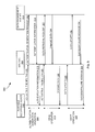
- FIG. 3 is a sequence diagram 300 illustrating a method for transferring data by a NFC tag 302, according to an embodiment.
- the data may be application data related to an application.
- the application data may be transferred based on "data transfer" program written to NFC tag 302.
- the data transfer operation for the application may be performed by executing the "data transfer" program written to the NFC tag 302.
- authentication generation operation 304 is initially performed to generate authentication information for the portable electronic device 306 of a user.
- the authentication generation operation 304 is performed, when the NFC tag is activated 308 for the first time.
- an authentication generation request may be sent 310 to data management system 312.
- the data management system 312 may generate authentication information for the portable electronic device 306.
- the data management system 306 forwards 314 the generated authentication information to the NFC tag 302.
- the authentication information may include a unique identification, generated by the data management system 312, for the portable electronic device 306.
- the NFC tag 302 may then forward 316 the authentication information to the portable electronic device 306.
- the generated authentication information may then be used for authenticating the portable electronic device 306, during any subsequent activation of the NFC tag 302 by the portable electronic device 306.
- a new portable electronic device of a set of portable electronic devices is activating an NFC tag for the first time.
- the NFC tag may send an authentication generation request to the data management system that is associated with the set of portable electronic devices.
- the data management system may in response send authentication information corresponding to the new portable electronic device that may be used for identifying the new portable electronic device, whenever the portable electronic device activates the NFC tag.
- the "data transfer" program written to the NFC tag may be used to perform a read operation 318 to read static and/or dynamic data from the data management system 312.
- the dynamic data may be application data related to a particular application.
- the application may be stored on the portable electronic device 306.
- An application or an "app” is computer software that performs useful tasks.
- the application may use the "data transfer" program written to the NFC tag for performing the useful task.
- the NFC tag 302 may initially be activated 320. The activated NFC tag 302 may then send 322 data retrieval request to the data management system 312. The data retrieval request may be sent for retrieving data related to a particular application.
- the data management system 312 may send 324 the requested data to the NFC tag 302.
- the NFC tag 302 may then forward 326 the received data, e.g., related to a particular application, to the portable electronic device 306.
- the NFC tag may send a data retrieval request to receive the dynamic "user profile" data, including the user's name, the user's current "cost center", the user's manager name, from a user data management system.
- a user name "ABCD”, user's cost center "1001", and user' s manager name “XYZ” retrieved from the data management system may be received as dynamic "user profile" data at the NFC tag.
- the NFC tag may then forward the dynamic "user profile" data to the portable electronic device.
- the "data transfer" program written to the NFC tag 302 may also be used to perform write operation 328 for writing data update related to an application to the data management system 312.
- the NFC tag 302 may receive 330 data update from the portable electronic device 306.
- the data update may be received in response to the dynamic data received at the portable electronic device 306, during the read operation 318.
- the data update may be triggered by a user of the portable electronic device 306.
- the user may input the data update at the portable electronic device 306 which may forward 330 the data update to the NFC tag 302.
- the data update received from the portable electronic device 306 may be stored in the NFC tag 302.
- the data update may be stored in the "data transfer" IC included in the NFC tag.
- the data update stored in the NFC tag 302 may be forwarded 332 to the data management system 312.
- the data management system 312 may send 334 a success or failure message depending on the success or failure in writing the data update to the data management system 312.
- the success/failure message is sent 336 to the portable electronic device 306.
- the user may provide a data update to correct the "cost center” information stored in the data management system.
- the received "cost center” information "1111” may then be stored on the NFC tag.
- the correct “cost center” information "1111” stored on the NFC tag may be forwarded and stored at the data management system, for updating the "cost center” information at the data management system.
- the NFC tag therefore allows the two way data communication between the data management system and the portable electronic device without requiring the user to login to the data management system.
- FIG. 4 is an exemplary user interface 400 of a portable electronic device displaying a graphical user interface of a leave request application 402, according to an embodiment.
- the leave request application 402 is used by the portable electronic device to to perform a leave request.
- the leave request may indicate the start date and end date of a disconnection (no network connection) period of the portable electronic device.
- the leave request is forwarded to a NFC tag that stores the leave request data.
- the leave request may be sent in response to receiving a request (via a selection of a button of the portable electronic device) from a user of the portable electronic device.
- Based on the "data transfer" program when the NFC tag storing the leave request data is activated, the stored leave request data is transferred to a data management system.
- the data management system may be a data server storing information on portable electronic devices.
- the data management system may then send a success message to the NFC tag when the leave request data is successfully written to the data management system, or a failure message when the leave request is not successfully written to the data management system.
- the NFC tag may forward the success or failure message to the portable electronic device.
- FIG. 5 is an exemplary user interface 500 of a portable electronic device displaying a success message 502, according to an embodiment.
- the success message 502 is forwarded by the NFC tag to the portable electronic device, after the NFC tag receives the success message from the data management system.
- the success message 502 indicates that the leave request has been successfully updated to the data management system.
- the NFC tag therefore allows the portable electronic device to successfully update the leave request data to the data management system without requiring to login or connect to the data management system.
- Some embodiments may include the above-described methods being written as one or more software components. These components, and the functionality associated may be used by client, server, distributed, or peer computer systems. These components may be written in a computer language corresponding to one or more programming languages such as, functional, declarative, procedural, object-oriented, lower level languages and the like. They may be linked to other components via various application programming interfaces and then compiled into one complete application for a server or a client. Alternatively, the components maybe implemented in server and client applications. Further, these components may be linked together via various distributed programming protocols. Some example embodiments may include remote procedure calls being used to implement one or more of these components across a distributed programming environment.
- a logic level may reside on a first computer system that is remotely located from a second computer system containing an interface level (e.g., a graphical user interface).
- interface level e.g., a graphical user interface
- first and second computer systems can be configured in a server-client, peer-to-peer, or some other configuration.
- the clients can vary in complexity from mobile and handheld devices, to thin clients and on to thick clients or even other servers.
- the above-illustrated software components are tangibly stored on a computer readable storage medium as instructions.
- the term "computer readable storage medium" should be taken to include a single medium or multiple media that stores one or more sets of instructions.
- computer readable storage medium should be taken to include any physical article that is capable of undergoing a set of physical changes to physically store, encode, or otherwise carry a set of instructions for execution by a computer system which causes the computer system to perform any of the methods or process steps described, represented, or illustrated herein.
- a computer readable storage medium may be a non-transitory computer readable storage medium.
- Examples of a non-transitory computer readable storage media include, but are not limited to: magnetic media, such as hard disks, floppy disks, and magnetic tape; optical media such as CD-ROMs, DVDs and holographic devices; magneto-optical media; and hardware devices that are specially configured to store and execute, such as application-specific integrated circuits ("ASICs"), programmable logic devices ("PLDs”) and ROM and RAM devices.
- Examples of computer readable instructions include machine code, such as produced by a compiler, and files containing higher-level code that are executed by a computer using an interpreter. For example, an embodiment may be implemented using Java, C++, or other object-oriented programming language and development tools. Another embodiment may be implemented in hard-wired circuitry in place of, or in combination with machine readable software instructions.
- FIG. 6 is a block diagram of an exemplary computer system 600.
- the computer system 600 includes a processor 602 that executes software instructions or code stored on a computer readable storage medium 622 to perform the above-illustrated methods.
- the processor 602 can include a plurality of cores.
- the computer system 600 includes a media reader 616 to read the instructions from the computer readable storage medium 622 and store the instructions in storage 1004 or in random access memory (RAM) 606.
- the storage 604 provides a large space for keeping static data where at least some instructions could be stored for later execution.
- the RAM 606 can have sufficient storage capacity to store much of the data required for processing in the RAM 606 instead of in the storage 604.
- the data required for processing may be stored in the RAM 606.
- the stored instructions may be further compiled to generate other representations of the instructions and dynamically stored in the RAM 606.
- the processor 602 reads instructions from the RAM 606 and performs actions as instructed.
- the computer system 600 further includes an output device 610 (e.g., a display) to provide at least some of the results of the execution as output including, but not limited to, visual information to users and an input device 612 to provide a user or another device with means for entering data and/or otherwise interact with the computer system 600.
- Such output devices 610 and input devices 612 could be joined by one or more additional peripherals to further expand the capabilities of the computer system 600.
- a network communicator 614 may be provided to connect the computer system 600 to a network 620 and in turn to other devices connected to the network 650 including other clients, servers, data stores, and interfaces, for instance.
- the modules of the computer system 600 are interconnected via a bus 618.
- Computer system 600 includes a data source interface 608 to access data source 624.
- the data source 624 can be accessed via one or more abstraction layers implemented in hardware or software.
- the data source 624 may be accessed by network 620.
- the data source 624 may be accessed via an abstraction layer, such as, a semantic layer.
- Data sources include sources of data that enable data storage and retrieval.
- Data sources may include databases, such as, relational, transactional, hierarchical, multi-dimensional (e.g., OLAP), object oriented databases, and the like.
- Further data sources include tabular data (e.g., spreadsheets, delimited text files), data tagged with a markup language (e.g., XML data), transactional data, unstructured data (e.g., text files, screen scrapings), hierarchical data (e.g., data in a file system, XML data), files, a plurality of reports, and any other data source accessible through an established protocol, such as, Open DataBase Connectivity (ODBC), produced by an underlying software system (e.g., ERP system), and the like.
- Data sources may also include a data source where the data is not tangibly stored or otherwise ephemeral such as data streams, broadcast data, and the like. These data sources can include associated data foundations, semantic layers, management systems,
- FIG. 7 is a flowchart of a method for controlling operation of a NFC tag e.g. the NFC tag 104 of FIG. 1 .
- the NFC tag may comprise for example a printed circuit board or an integrated circuit e.g. 106 of FIG. 1 , a chip card.
- the NFC tag may comprise for example a first and a second communication interface, a memory module, and a command processing unit.
- the memory module may comprise a non-volatile memory and a volatile memory.
- the first communication interface may be connected to a NFC antenna in order to communicate with at least one external mobile telecommunication device (e.g. as soon as the mobile telecommunication device taps on the NFC tag) of a set of mobile telecommunication devices such as electronic device 102 of FIG. 1 .
- the set of mobile telecommunication devices may be authorized to access the NFC tag.
- the second communication interface may be used for a wired communication (e.g. via a serial link) with a database system or database server e.g. data management system 110 of FIG 1 .
- the first mobile telecommunication device may comprise a, smartphone, a PDA and the like.
- the second communication interface may be connected to a line used in communication for transmitting or receiving power-supply voltage, transmission and receiving signal, and thereby communicates with the database system.
- the memory module (e.g. the non-volatile memory) is configured to store access information corresponding to the set of mobile telecommunication devices. However; since the memory is limited in size a maximum data storage amount per mobile telecommunication device of the set of the mobile telecommunication devices may not be exceeded; otherwise the access information that exceeds that maximum may be stored in the database system. In another example, the access information that is stored in the NFC tag may be duplicated in the database system.
- the NFC tag may be used to control access of the set of mobile telecommunication devices to a data communication unit.
- the data communication unit may comprise for example a WiFi network access point and/or a GSM network access point.
- the first mobile telecommunication device may contact the NFC tag to get an authorization or to be allowed to use access wireless network provided by the WiFi network access point may contact again the NFC tag for logging out e.g. this login and logout process may be needed for controlling the time the first mobile telecommunication device has spent connected to the WiFi e.g. per day.
- the access information associated with a given mobile telecommunication device of the set of mobile telecommunication devices may indicate the number of times the given mobile telecommunication device accessed (e.g. tapped) the NFC tag.
- the access information may indicate the time duration of access or usage of the given mobile telecommunication device into the WiFi e.g. per day.
- the present method may allow to control access of the set of mobile telecommunication devices e.g. to the data communication unit (how long and often they connect).
- the NFC tag may have multiple operation modes.
- the NFC tag may operate in accordance with a first operation mode e.g. in the first operation mode the NFC tag may communicate using an NFC protocol.
- the NFC tag may receive from a first mobile telecommunication device of the set of telecommunication devices via the NFC antenna a data request for providing access information of the first mobile telecommunication device.
- the data request may be automatically received or sent by for example "swiping,” “tapping,” “bumping” or otherwise moving the first mobile telecommunication device in close proximity to the NFC tag.
- the first mobile telecommunication device may use its built-in NFC reader or writer to transmit the data request to the NFC tag as soon as the NFC tag is detected within e.g. the 5-centimeter read range.
- the NFC tag may authenticate in step 702 (e.g. using the command processing unit) the first mobile telecommunication device to determine whether the first mobile telecommunication device is allowed to access the wireless network provided by the WiFi network access point. If it is allowed the NFC tag may send an unlock signal to the WiFi network access point to authorize access to the first mobile telecommunication device.
- the NFC tag may authenticate (e.g. using the command processing unit) the first mobile telecommunication device to determine that a user of the first mobile telecommunication device is allowed to access or enter a building that can only be accessed via an automatic door. And the NFC tag may send an unlock signal to an automatic door opening and closing system via the database system for enabling (e.g. an automatic door opens) access to the user.
- the NFC tag may determine an access frequency of the first mobile telecommunication device to the NFC tag e.g. how often the first mobile telecommunication device has communicated with the NFC tag.
- the first mobile telecommunication device may have a daily login and logout to the WiFi network.
- the access frequency may for example be 60 times per month (i.e. 30 days).
- the NFC tag may compare the determined access frequency with a predefined maximum frequency. This may determine the type of access to data as explained below.
- the maximum frequency may be determined using the number of mobile telecommunication devices of the set of mobile telecommunication devices and the memory size of the NFC tag (e.g. the size of the non-volatile memory).
- the memory size may be equally divided over the set of mobile telecommunication devices.
- the portion of the memory size that is assigned to each mobile telecommunication device of the set of mobile telecommunication devices may be a maximum size.
- the memory size may be divided based on a ranking of the set of mobile telecommunication device based on a ranking criterion wherein each mobile telecommunication device of the set of mobile telecommunication devices may be assigned a maximum memory size depending on the rank assigned to the mobile telecommunication device.
- the ranking criterion may comprise for example the amount of data stored for each mobile telecommunication device in the database system and/or the NFC tag. The more data stored of a mobile telecommunication device the highest the ranking assigned to the mobile telecommunication device.
- the maximum size may be either determined individually for each mobile telecommunication device of the set of telecommunication devices or be determined collectively (e.g. equally) for the set of mobile telecommunication device.
- the maximum frequency may be determined because the maximum size and the maximum frequency are linearly related since in the present case of the data being stored is related to access information.
- the size required for storing such access information may be the size for storing the number of accesses and corresponding days. Knowing that the access frequency of the first mobile telecommunication device is 60 times per month (e.g. 2 times per day) this may require the storage 30 times of the number of accesses (e.g. number 2) and the associated day (e.g. day 1 or day 2 etc.). If for example, the maximum size determined above can only contain 20 times the number of accesses and the corresponding days, then the maximum frequency may be 20 access per month (e.g. when two accesses are performed per day).
- steps 707-713 may be executed.
- the fact that the access frequency is higher than the predetermined maximum frequency may indicate that the access information of the first mobile telecommunication device are stored on the database system e.g. because there are not enough space to store them locally because of the high access frequency of the first mobile telecommunication device.
- the NFC tag may establish a communication link to the database system.
- the NFC tag may be connected to the database system via a serial link, and the establishing of the communication link may be performed by sending a link setup command to the database system via the serial ink for establishing the communication link.
- the communication link between the NFC tag and the database system may be a logical link wherein the physical transmission of data is done between the NFC tag and the database system via the mobile telecommunication device. This may be advantageous as it may provide a controlled access to data using the NFC tag i.e. the access information has to pass through the NFC tag before being used by the first mobile telecommunication device.
- the NFC tag may switch its operation to a second operation mode for communication with the database system e.g. via the second communication interface e.g. instead of communicating via the NFC protocol another communication protocol may be used in order to communicate through the serial link with the database system.
- the NFC tag may be power supplied by the database system.
- the NFC tag may forward the data request to the database system using the communication link.
- the NFC tag may receive, in step 713, the access information of the first mobile telecommunication device from the database system via the communication link.
- the access information received from the database system may be stored (e.g. temporally) in the volatile memory before until performing step 713.
- the NFC tag may switch back to the first operation mode and send the received access information to the first mobile telecommunication device via the NFC antenna.
- the NFC tag may send in step 715 the first mobile telecommunication device via the NFC antenna the access information of the first mobile telecommunication device that are stored locally (e.g. because of their size being smaller than the maximum size).
Landscapes
- Engineering & Computer Science (AREA)
- Business, Economics & Management (AREA)
- Human Resources & Organizations (AREA)
- Computer Networks & Wireless Communication (AREA)
- Signal Processing (AREA)
- Strategic Management (AREA)
- Physics & Mathematics (AREA)
- General Physics & Mathematics (AREA)
- Theoretical Computer Science (AREA)
- Entrepreneurship & Innovation (AREA)
- Economics (AREA)
- General Business, Economics & Management (AREA)
- Marketing (AREA)
- Accounting & Taxation (AREA)
- Finance (AREA)
- Data Mining & Analysis (AREA)
- Operations Research (AREA)
- Quality & Reliability (AREA)
- Tourism & Hospitality (AREA)
- Microelectronics & Electronic Packaging (AREA)
- Computer Security & Cryptography (AREA)
- Computer Hardware Design (AREA)
- Development Economics (AREA)
- Technology Law (AREA)
- Telephone Function (AREA)
- Telephonic Communication Services (AREA)
- Information Transfer Between Computers (AREA)
- Mobile Radio Communication Systems (AREA)
Abstract
Description
- Near field communication, or NFC, is a set of short-range wireless technologies. NFC standards cover communications protocols and data exchange formats, and are based on existing Radio Frequency. NFC generally involves a NFC tag. Although the integration of the NFC technology in electronic systems has rapidly increased and spread throughout the industry, the use of NFC tags has lagged substantially behind.
- Various embodiments provide a communication method, a NFC tag and an access control system as described by the subject matter of the independent claims. Advantageous embodiments are described in the dependent claims.
- In one aspect, the invention relates to a communication method for controlling operation of a near field communication, NFC, tag, wherein the NFC tag is operating in accordance with a first operation mode. The method comprises:
- receiving from a first mobile telecommunication device via a NFC antenna of the NFC tag a data request for providing access information of the first mobile telecommunication device;
- determining an access frequency of the first mobile telecommunication device to the NFC tag;
- in response to a determination that the access frequency is higher than a predetermined maximum frequency;
- establishing a communication link to a database system connected to the NFC tag;
- switching the NFC tag to a second operation mode for communication with the database system;
- forwarding the data request to the database system using the communication link;
- receiving the access information from the database system via the communication link;
- switching back to the first operation mode and sending the received access information to the first mobile telecommunication device via the NFC antenna.
- in response to a determination that the access frequency is smaller than the predetermined maximum frequency sending the first mobile telecommunication device via the NFC antenna locally stored access information data in response to the data request.
- The NFC tag may store locally an amount of data smaller than a predefined threshold e.g. 1% of the total size of the non-volatile memory of the NFC tag. For example, the database system may store data related to the first mobile telecommunication that in amount smaller (e.g. 10% smaller) than the storage size (e.g. volatile and/or non-volatile memory size) of the NFC tag. Storing data locally may be advantageous as it may speed up the data access process compared to the case where data is stored in the database system.
- The first mobile telecommunication device may be an NFC enabled device.
- These features may have the advantage of providing a controlled, optimal and efficient access to data using the NFC tag. These features may provide access to up-to-date dynamic data that may change over time. The change over time may lead to an increase in the amount of the accessed data which then may be stored on the database system if there is not enough space in the NFC tag.
- According to one embodiment, the determining of the access frequency further comprising: in response to a determination that the number of access of the access frequency is an odd number rejecting the data request ((and leaving the method)).
- This embodiment may provide a secure access to the access information by preventing potential malicious access by suspicious devices. For example, mobile telecommunication devices may be controlled to use or contact the NFC tag for logging e.g. to a WiFi network, and another time for logging out. This means that when the first mobile telecommunication device has access the NFC tag e.g. 59 times per month means that in a given day (e.g. the last day of the month) the first mobile telecommunication device has logged in without logging out in the given day which may be an indication of a suspicious act by the first mobile telecommunication device.
- According to one embodiment, the first mobile telecommunication device is part of a set of mobile telecommunication devices that are authorized to access the NFC tag, wherein the maximum frequency is determined using the number of mobile telecommunication devices of the set of mobile telecommunication devices and a memory size of the NFC tag.
- This embodiment may be advantageous as it may make use of the type of data being stored that is related to access information only for further increasing the access efficiency to the access information.
- According to one embodiment, the first mobile telecommunication device is part of a set of mobile telecommunication devices that are authorized to access the NFC tag. The method further comprises receiving from a second mobile telecommunication device of the set of mobile telecommunication devices via the NFC antenna another data request for providing access information of the second mobile telecommunication device; in response to a determination that an access frequency of the second mobile telecommunication device is equal to the access frequency of the first mobile telecommunication device; sending an identification address of the first mobile telecommunication device to the second mobile telecommunication device in response to the received data request.
- This may further increase the access efficiency to the access information by avoiding the submission of the same information twice to the two different mobile telecommunication devices. For example, in since the first and second mobile telecommunication devices have the same access frequencies, their corresponding access information e.g. the number of access may be the same. In this case the second mobile telecommunication device may use the access information sent to the first mobile telecommunication device e.g. by communicating with the first mobile telecommunication device.
- According to one embodiment, the method further comprises receiving via the NFC antenna from the first mobile telecommunication device a data update in response to receiving the requested data at the first mobile telecommunication device; switching to the second operation mode and forwarding the data update to the database system using the communication link. This may for example provide up-to-date access information for subsequent access to the access information of the first mobile telecommunication device.
- According to one embodiment, the switching step comprising: authenticating the first mobile telecommunication device; and in case the authentication is successful, forwarding the stored data update to the database system. This may provide a secure method as the first mobile telecommunication device may only have the read access right but not the write access right. This may control access to data stored in the NFC tag or the database system.
- According to one embodiment, the method further comprises sending an unlock signal to a data communication unit via the database system for authorizing access of the first telecommunication device to the data communication unit. For example, the NFC tag may send the unlock signal to the database system and control the database system to forward the unlock signal to the data communication unit.
- This may have the advantage of making use of a single connection to provide both the access information requested by the first mobile telecommunication device and to allow the first mobile telecommunication device to access the data communication unit. This may save resources that would otherwise be required for running separately the access permission and the data update.
- In another example, the method further comprises sending an unlock signal to an automatic door opening and closing system via the database system for enabling (e.g. an automatic door opens) a user of the first mobile telecommunication device to access or enter a building that can only be accessed via the automatic door.
- According to one embodiment, the access information comprises at least one of: a number of accesses of the first mobile telecommunication device to the NFC tag; an average access duration per a predefined time period of the first mobile telecommunication device.
- According to one embodiment, in response to a determination that the access frequency is smaller than a predetermined minimum frequency rejecting the data request (and leaving the method). This may provide a secure access to the access information as a small access frequency (e.g. 0) may be an indication of a malicious access attempt.
- According to one embodiment, the NFC tag is connected to the database system via a serial link, wherein establishing the communication link comprises sending a link setup command to the database system via the serial ink for establishing the communication link.
- For example, before the switching to the second operation mode the NFC tag is powered using the NFC antenna, wherein after establishing the communication link the NFC tag is power supplied by the database system via a serial link between the NFC tag and the database system.
- In another aspect, the invention relates to a NFC tag comprising a NFC antenna, the NFC tag operating in a first operation mode, wherein the NFC tag is configured for:
- receiving from a first mobile telecommunication device via a NFC antenna of the NFC tag a data request for providing access information of the first mobile telecommunication device;
- determining an access frequency of the first mobile telecommunication device to the NFC tag;
- in response to a determination that the access frequency is higher than a predetermined maximum frequency;
- establishing a communication link to a database system connected to the NFC tag;
- switching the NFC tag to a second operation mode for communication with the database system;
- forwarding the data request to the database system using the communication link;
- receiving the access information from the database system via the communication link;
- switching back to the first operation mode and sending the received access information to the first mobile telecommunication device via the NFC antenna.
- in response to a determination that the access frequency is smaller than the predetermined maximum frequency sending the first mobile telecommunication device via the NFC antenna locally stored access information data in response to the data request.
- In another aspect, the invention relates to an access control system comprising a NFC tag, a mobile telecommunication device and a database server according to the previous embodiment. The database server may be configured for receiving a data request from the NFC tag and for sending in response to the received data request the access information via the communication link to the NFC tag. The mobile telecommunication device is an NFC enabled device. The mobile telecommunication device may be configured for sending to the NFC tag a data request for providing access information of the first mobile telecommunication device and fore receiving the access information from the mobile telecommunication device.
- According to one embodiment, the access control system further comprises a data communication configured for providing a network access to the mobile telecommunication device.
- In another aspect, the invention relates to a computer implemented method for near field communication (NFC) based data transfer. The method comprises a NFC tag, receiving dynamic data from a data management system; the NFC tag, forwarding the received dynamic data to a portable electronic device; based on the forwarded dynamic data, the NFC tag receiving data update from the portable electronic device; and forwarding, by the NFC tag, received data update to the data management system.
- According to one embodiment, the method further comprises the portable electronic device, activating the NFC tag; receiving, at the portable electronic device, the dynamic data for an application stored at the portable electronic device; at the portable electronic device, displaying the received dynamic data; based on the displayed dynamic data, receiving, at the portable electronic device, the data update; and the portable electronic device, forwarding the data update to the NFC tag.
- According to one embodiment, the method further comprises storing the received data update to the NFC tag.
- According to one embodiment, the method further comprises based on activating the NFC tag, detecting the stored data update at the portable electronic device; and forwarding the stored data update to the data management system.
- According to one embodiment, the method further comprises the NFC tag, authenticating the portable electronic device; and based on the authentication, the NFC tag forwarding the stored data update to the data management system.
- According to one embodiment, the method further comprises the NFC tag, sending a data retrieval request to the data management system; and based on the data retrieval request, the NFC tag receiving the dynamic data from the data management system.
- According to one embodiment, the method further comprises programming, by a processor of a computer, the NFC tag to transfer data between the portable electronic device and the data management system.
- In another aspect, the invention relates to a computer system for near field communication (NFC) based data transfer. The computer system comprises: a processor to execute a program code; and a memory coupled to the processor, the memory storing the program code comprising: receive, by a NFC tag, dynamic data from a data management system; forward, by the NFC tag, the received dynamic data to a portable electronic device; based on the forwarded dynamic data, receive, by the NFC tag, data update from the portable electronic device; and forward received data update to the data management system.
- In another aspect, the invention relates to an article of manufacture including a non-transitory computer readable storage medium to tangibly store instructions, which when executed by a computer, cause the computer to: receive, by a near field communication (NFC) tag, dynamic data from a data management system; forward, by the NFC tag, the received dynamic data to a portable electronic device; based on the forwarded dynamic data, receive, by the NFC tag, data update from the portable electronic device; and forward received data update to the data management system.
- In another aspect, the invention relates to an article of manufacture including a non-transitory computer readable storage medium to tangibly store instructions, which when executed by a computer, cause the computer to: activate a near field communication (NFC) tag by a portable electronic device; send a data retrieval request, by the activated NFC tag, to retrieve dynamic data from a data management system; based on the data retrieval request, receive the dynamic data from the data management system; forward, by the NFC tag, the received dynamic data to the portable electronic device; based on the forwarded dynamic data, receive, by the NFC tag, data update from the portable electronic device; store the received data update to the NFC tag; and forward the received data update to the data management system.
- The claims set forth the embodiments of the invention with particularity. The invention is illustrated by way of example and not by way of limitation in the figures of the accompanying drawings in which like references indicate similar elements. The embodiments of the invention, together with its advantages, may be best understood from the following detailed description taken in conjunction with the accompanying drawings.
-
FIG. 1 is a flow diagram illustrating a process for near field communication (NFC) based data transfer, according to an embodiment. -
FIGS. 2A-2B are flow diagrams illustrating an algorithm for a "data transfer" method written to a NFC tag, according to an embodiment. -
FIG. 3 is a sequence diagram illustrating a method for transferring data by a NFC tag, according to an embodiment. -
FIG. 4 is an exemplary user interface of a portable electronic device displaying a graphical user interface of a leave request application, according to an embodiment. -
FIG. 5 is an exemplary user interface of a portable electronic device displaying a success message, according to an embodiment. -
FIG. 6 is a block diagram illustrating a computing environment of near field communication based data transfer, according to an embodiment. -
FIG. 7 is a flowchart a method for controlling operation of a NFC tag. - Embodiments of techniques for near field communication based data transfer are described herein. In the following description, numerous specific details are set forth to provide a thorough understanding of embodiments of the invention. One skilled in the relevant art will recognize, however, that the invention can be practiced without one or more of the specific details, or with other methods, components, materials, etc. In other instances, well-known structures, materials, or operations are not shown or described in detail to avoid obscuring aspects of the invention.
- Reference throughout this specification to "one embodiment", "this embodiment" and similar phrases, means that a particular feature, structure, or characteristic described in connection with the embodiment is included in at least one embodiment. Thus, the appearances of these phrases in various places throughout this specification are not necessarily all referring to the same embodiment. Furthermore, the particular features, structures, or characteristics may be combined in any suitable manner in one or more embodiments.
-
FIG. 1 is a block diagram illustrating aprocess 100 for near field communication based data transfer, according to an embodiment. Near field communication (NFC) is a set of standards to establish radio communication between two devices which are in direct contact or within a predetermined range, for example, 10 centimeters, from each other. In one embodiment, the near field communication is established between portableelectronic device 102 andNFC tag 104. TheNFC tag 104 is a passive device, for example, a sticker or a wristband, which includes "data transfer" integrated circuit (IC) 106. The "data transfer"IC 106 of theNFC tag 104 controls data transfer by theNFC tag 104. The portableelectronic device 102 may be a handheld or wearable electronic device, for example, mobile phone, tablet computer, laptop, personal digital assistant, etc. In one embodiment, the portableelectronic device 102 is a NFC enabled portable electronic device that may establish NFC communication with theNFC tag 104. The portableelectronic device 102 may include data transmitter-receiver module 108 for writing data to theNFC tag 104 and receiving data from theNFC tag 104. - In one embodiment, the
NFC tag 104 may be programmed to facilitate data transfer between the portableelectronic device 102 anddata management system 110. Thedata management system 110 may be a data server that stores and processes data. In one embodiment, thedata management system 110 may be provided in a cloud. Cloud computing addresses a variety of computing concepts that involve a large number of computers connected through a real-time communication network such as the Internet. In one embodiment, programming theNFC tag 104 may include writing a "data transfer" program to the "data transfer"IC 106 of theNFC tag 104. The "data transfer" program defines a sequence of data transfer steps for two-way communication between the portableelectronic device 102 and theNFC tag 104. For example, the data transfer steps in the "data transfer" program may include: initially sending data retrieval request 112 to thedata management system 110. Next, theNFC tag 104 may receive 114 data from thedata management system 110, in response to the data retrieval request. Next, theNFC tag 104forwards 116 the received data to the portableelectronic device 102. Based on the received data, the portableelectronic device 102 may send 118 data update to theNFC tag 104. TheNFC tag 104 may finally forward 120 the received data update to thedata management system 110. - In one embodiment, several applications may use the "data transfer" program, written to the "data transfer"
IC 106 of theNFC tag 104. The applications may use the "data transfer" program to perform application data transfer between the portableelectronic device 102 and thedata management system 110, at runtime. An application or an "app" is computer software that when executed performs a useful task. In one embodiment, the applications may also be written to the "data transfer"IC 106 included in theNFC tag 104. The applications may be included in the "data transfer" program written to the "data transfer"IC 106 of theNFC tag 104. Alternatively, the application may be a stand-alone application written to the "data transfer"IC 106 of theNFC tag 104. - In one embodiment, the
NFC tag 104 allows a user of the portableelectronic device 102 to access and update application data to thedata management system 110, without requiring the user of the portableelectronic device 102 to login to thedata management system 110. Specifically, the data transfer steps included in the "data transfer" program written to theNFC tag 104 allows application data transfer between the portableelectronic device 102 and thedata management system 110, without requiring the user to login to thedata management system 110. - For example, consider a "time recording" application that is used for recording time spent by a an NFC enabled portable electronic device (or potable electronic device) on a particular connection task e.g. connection time to a wireless netwok. In this case the "data transfer" program, included in the NFC tag, may facilitate data transfer between the NFC enabled portable electronic device and a data management system that manages information of portable electronic devices, including time spent by the NFC enabled portable electronic device on a particular connection task or session. The data transfer steps defined by the "data transfer" program may be used for transferring "time recording" application data between the data management system and the portable electronic device. Based on the "data transfer" program, initially the NFC tag may send a "data retrieval" request for receiving "time recording" data, for example, the "time spent" information that includes information of the time spent by the NFC enabled portable electronic device on different connection sessions. Based on the "data retrieval" request, the NFC tag receives the "time recording" data that includes, e.g., session names "Alpha" and "Beta", identification address of the NFC enabled portable electronic device "IJKL", and the time spent as "3 days" and "1 day" for sessions "Alpha" and "Beta", respectively, from the data management system. Next, the NFC tag forwards the "time recording" data to the portable electronic device. The NFC enabled portable electronic device may then update (automatically or upon receiving update data e.g. from a user of the portable electronic device) the "time recording" data for session "Beta" from "1 day" to "2 days", at the portable electronic device. The updated "time recording" data "2 days" is then forwarded to the NFC tag. Next, the NFC tag forwards the updated "time recording" data to the data management system that may be finally updated to the data management system.
- In the "time recording" example described in the previous paragraph, the portable electronic device retrieves "time recording" data from the data management system and updates the "time recording" data to the data management system, using the NFC tag, without connecting to a network or the data management system. The NFC tag therefore allows a user to conveniently access and update application data without requiring a login to the data management system.
- The programmed
NFC tag 104, including the "data transfer" program, can be used by any number of applications that require one-way or two-way communication between the portableelectronic device 102 and thedata management system 110 to transfer application data. For example, the programmedNFC tag 104 may be used by a "leave request" application that requires a one-way communication to push a leave request, from the portableelectronic device 102, to thedata management system 110, without a user logging to thedata management system 110. -
FIGS. 2A-2B are flow diagrams illustrating an algorithm for "data transfer"process 200 written to an NFC tag, according to an embodiment. The "data transfer"process 200 may define data transfer steps for transferring data between two devices, for example, a portable electronic device and a data management system. In one embodiment, the "data transfer" method may be included in a "data transfer" program that is written to a "data transfer" IC included in the NFC tag. After the write operation, the steps included in the "data transfer" method may be used to transfer application data, of an application, between the portable electronic device and the data management system. - In one embodiment the "data transfer"
process 200 includes initially, at 202 (FIG. 2A ), activating the NFC tag by a portable electronic device. NFC tag, or a smart tag, may be a passive device that is capable of NFC communication. A passive device is a device that does not require a source of energy for its operation. The NFC tag may be activated based on the magnetic field induced by a NFC enabled portable electronic device that is in contact or proximity of the NFC tag. The NFC tag may be activated by a NFC enabled portable electronic device. - Next, a check is performed to determine whether the NFC tag is being activated for first time (at 204). The NFC tag may be activated for the first time when the NFC enabled portable electronic device is in contact or in proximity of the NFC tag, for the first time. In case the NFC tag is activated for the first time, authentication information is generated for the portable electronic device of the user, at 206. During the authentication information generation operation, a unique identification key may be generated and linked to user identification information related to the user of the portable electronic device.
- Next, at 208 (
FIG. 2B ), after the generation of authentication information, the NFC tag may send a data retrieval request to the data management system. The data retrieval request may be sent to retrieve data from the data management system. Based on the data retrieval request, the NFC tag may receive data from the data management system (at 210). In one embodiment, the data received by the NFC tag is dynamic data. Dynamic data denotes data that is asynchronously changed as further updates to the data become available. For example, "number of hours spent" on a project, by a user, is a dynamic data that changes based on the time spent by the user working on the project. In one embodiment, the NFC tag is programmed to receive and send dynamic data. - Next, at 212, the NFC tag may forward the dynamic data received from the data management system to the portable electronic device. In one embodiment, data update may be received at the portable electronic device. A user of the portable electronic device may want to update the dynamic data received from the NFC tag. In this case, the user may provide the data update at the portable electronic device. The data update may be an updated version of the dynamic data received from the data management system. In one embodiment, the data update is the most recent version of the dynamic data that the user wants to upload to the data management system. For example, consider that the data received from the data management system is user's leave data that includes the number of leaves the user has applied for in a particular year. In case the leave data is incorrect, then the user may provide, at the portable electronic device, a leave data update with the correct number of leaves that the user wants to update to the data management system. The data update received at the portable electronic device may then be forwarded at 214, to an NFC tag that stores (218) the data update received from the portable electronic device. The data update may be stored in the "data transfer" IC included in the NFC tag.
- When the NFC tag is activated and it is determined that the NFC tag has been activated before, a check is performed at 218 (
FIG. 2A ) to identify whether any data update for the dynamic data is stored on the NFC tag. In case, a data update is stored on the NFC tag, then a data authentication check may be performed at 220 to determine whether the data update is being received from an authenticated portable electronic device. The check at 220 may be performed based on the authentication information generated for the portable electronic device at 206. In case the device is an un-authenticated portable electronic device, an error message may be sent, at 222, to the user of the portable electronic device. In case the data update is received from an authenticated portable electronic device the data update stored on the NFC tag is forwarded to the data management system (224). - After the "data transfer" program including the "data transfer" process is written to the NFC tag, an application may use the "data transfer"
process 200 to transfer data between the portable electronic device and the data management system. In one embodiment, some applications may use a portion of the data transfer steps included in the "data transfer"process 200 for transferring application data. For example, consider a "hotel booking" application on the portable electronic device. A user may provide details of the hotel booking that may be sent to the NFC tag. The NFC tag may store the hotel booking information received from the user. On the next NFC tag activation, the hotel booking information of the user may be transferred to the data management system. In this case, the "hotel booking" application only used the steps 218-224 of the "data transfer" program for transferring application data. -
FIG. 3 is a sequence diagram 300 illustrating a method for transferring data by aNFC tag 302, according to an embodiment. The data may be application data related to an application. The application data may be transferred based on "data transfer" program written toNFC tag 302. In one embodiment, the data transfer operation for the application may be performed by executing the "data transfer" program written to theNFC tag 302. For performing the data transfer operation,authentication generation operation 304 is initially performed to generate authentication information for the portableelectronic device 306 of a user. In one embodiment, theauthentication generation operation 304 is performed, when the NFC tag is activated 308 for the first time. When theNFC tag 302 is activated 308 by portableelectronic device 306 for the first time, then an authentication generation request may be sent 310 todata management system 312. In response, thedata management system 312 may generate authentication information for the portableelectronic device 306. Thedata management system 306forwards 314 the generated authentication information to theNFC tag 302. In one embodiment, the authentication information may include a unique identification, generated by thedata management system 312, for the portableelectronic device 306. TheNFC tag 302 may then forward 316 the authentication information to the portableelectronic device 306. The generated authentication information may then be used for authenticating the portableelectronic device 306, during any subsequent activation of theNFC tag 302 by the portableelectronic device 306. - For example, consider a new portable electronic device of a set of portable electronic devices is activating an NFC tag for the first time. After the activation, the NFC tag may send an authentication generation request to the data management system that is associated with the set of portable electronic devices. The data management system may in response send authentication information corresponding to the new portable electronic device that may be used for identifying the new portable electronic device, whenever the portable electronic device activates the NFC tag.
- Next, after the
authentication generation operation 304, the "data transfer" program written to the NFC tag may be used to perform aread operation 318 to read static and/or dynamic data from thedata management system 312. The dynamic data may be application data related to a particular application. In one embodiment, the application may be stored on the portableelectronic device 306. An application or an "app" is computer software that performs useful tasks. In one embodiment, the application may use the "data transfer" program written to the NFC tag for performing the useful task. For reading the dynamic data, theNFC tag 302 may initially be activated 320. The activatedNFC tag 302 may then send 322 data retrieval request to thedata management system 312. The data retrieval request may be sent for retrieving data related to a particular application. Based on the received request, thedata management system 312 may send 324 the requested data to theNFC tag 302. TheNFC tag 302 may then forward 326 the received data, e.g., related to a particular application, to the portableelectronic device 306. For example, assume that a "user profile" application is stored at the portable electronic device. For reading application data related to the "user profile" application, the NFC tag may send a data retrieval request to receive the dynamic "user profile" data, including the user's name, the user's current "cost center", the user's manager name, from a user data management system. A user name "ABCD", user's cost center "1001", and user' s manager name "XYZ" retrieved from the data management system may be received as dynamic "user profile" data at the NFC tag. The NFC tag may then forward the dynamic "user profile" data to the portable electronic device. - In one embodiment, the "data transfer" program written to the
NFC tag 302 may also be used to performwrite operation 328 for writing data update related to an application to thedata management system 312. For thewrite operation 328, theNFC tag 302 may receive 330 data update from the portableelectronic device 306. The data update may be received in response to the dynamic data received at the portableelectronic device 306, during the readoperation 318. The data update may be triggered by a user of the portableelectronic device 306. The user may input the data update at the portableelectronic device 306 which may forward 330 the data update to theNFC tag 302. In one embodiment, the data update received from the portableelectronic device 306 may be stored in theNFC tag 302. The data update may be stored in the "data transfer" IC included in the NFC tag. Next, when theNFC tag 302 is activated, the data update stored in theNFC tag 302 may be forwarded 332 to thedata management system 312. In response, thedata management system 312 may send 334 a success or failure message depending on the success or failure in writing the data update to thedata management system 312. Finally, the success/failure message is sent 336 to the portableelectronic device 306. - In the "user profile" application example, the user may provide a data update to correct the "cost center" information stored in the data management system. The received "cost center" information "1111" may then be stored on the NFC tag. The correct "cost center" information "1111" stored on the NFC tag may be forwarded and stored at the data management system, for updating the "cost center" information at the data management system. The NFC tag therefore allows the two way data communication between the data management system and the portable electronic device without requiring the user to login to the data management system.
-
FIG. 4 is anexemplary user interface 400 of a portable electronic device displaying a graphical user interface of aleave request application 402, according to an embodiment. Theleave request application 402 is used by the portable electronic device to to perform a leave request. the leave request may indicate the start date and end date of a disconnection (no network connection) period of the portable electronic device. The leave request is forwarded to a NFC tag that stores the leave request data. The leave request may be sent in response to receiving a request (via a selection of a button of the portable electronic device) from a user of the portable electronic device. Based on the "data transfer" program, when the NFC tag storing the leave request data is activated, the stored leave request data is transferred to a data management system. The data management system may be a data server storing information on portable electronic devices. The data management system may then send a success message to the NFC tag when the leave request data is successfully written to the data management system, or a failure message when the leave request is not successfully written to the data management system. The NFC tag may forward the success or failure message to the portable electronic device. -
FIG. 5 is anexemplary user interface 500 of a portable electronic device displaying asuccess message 502, according to an embodiment. Thesuccess message 502 is forwarded by the NFC tag to the portable electronic device, after the NFC tag receives the success message from the data management system. Thesuccess message 502 indicates that the leave request has been successfully updated to the data management system. The NFC tag therefore allows the portable electronic device to successfully update the leave request data to the data management system without requiring to login or connect to the data management system. - Some embodiments may include the above-described methods being written as one or more software components. These components, and the functionality associated may be used by client, server, distributed, or peer computer systems. These components may be written in a computer language corresponding to one or more programming languages such as, functional, declarative, procedural, object-oriented, lower level languages and the like. They may be linked to other components via various application programming interfaces and then compiled into one complete application for a server or a client. Alternatively, the components maybe implemented in server and client applications. Further, these components may be linked together via various distributed programming protocols. Some example embodiments may include remote procedure calls being used to implement one or more of these components across a distributed programming environment. For example, a logic level may reside on a first computer system that is remotely located from a second computer system containing an interface level (e.g., a graphical user interface). These first and second computer systems can be configured in a server-client, peer-to-peer, or some other configuration. The clients can vary in complexity from mobile and handheld devices, to thin clients and on to thick clients or even other servers. The above-illustrated software components are tangibly stored on a computer readable storage medium as instructions. The term "computer readable storage medium" should be taken to include a single medium or multiple media that stores one or more sets of instructions. The term "computer readable storage medium" should be taken to include any physical article that is capable of undergoing a set of physical changes to physically store, encode, or otherwise carry a set of instructions for execution by a computer system which causes the computer system to perform any of the methods or process steps described, represented, or illustrated herein. A computer readable storage medium may be a non-transitory computer readable storage medium. Examples of a non-transitory computer readable storage media include, but are not limited to: magnetic media, such as hard disks, floppy disks, and magnetic tape; optical media such as CD-ROMs, DVDs and holographic devices; magneto-optical media; and hardware devices that are specially configured to store and execute, such as application-specific integrated circuits ("ASICs"), programmable logic devices ("PLDs") and ROM and RAM devices. Examples of computer readable instructions include machine code, such as produced by a compiler, and files containing higher-level code that are executed by a computer using an interpreter. For example, an embodiment may be implemented using Java, C++, or other object-oriented programming language and development tools. Another embodiment may be implemented in hard-wired circuitry in place of, or in combination with machine readable software instructions.
-
FIG. 6 is a block diagram of anexemplary computer system 600. Thecomputer system 600 includes aprocessor 602 that executes software instructions or code stored on a computerreadable storage medium 622 to perform the above-illustrated methods. Theprocessor 602 can include a plurality of cores. Thecomputer system 600 includes amedia reader 616 to read the instructions from the computerreadable storage medium 622 and store the instructions in storage 1004 or in random access memory (RAM) 606. Thestorage 604 provides a large space for keeping static data where at least some instructions could be stored for later execution. According to some embodiments, such as some in-memory computing system embodiments, theRAM 606 can have sufficient storage capacity to store much of the data required for processing in theRAM 606 instead of in thestorage 604. In some embodiments, the data required for processing may be stored in theRAM 606. The stored instructions may be further compiled to generate other representations of the instructions and dynamically stored in theRAM 606. Theprocessor 602 reads instructions from theRAM 606 and performs actions as instructed. According to one embodiment, thecomputer system 600 further includes an output device 610 (e.g., a display) to provide at least some of the results of the execution as output including, but not limited to, visual information to users and aninput device 612 to provide a user or another device with means for entering data and/or otherwise interact with thecomputer system 600.Such output devices 610 andinput devices 612 could be joined by one or more additional peripherals to further expand the capabilities of thecomputer system 600. Anetwork communicator 614 may be provided to connect thecomputer system 600 to anetwork 620 and in turn to other devices connected to the network 650 including other clients, servers, data stores, and interfaces, for instance. The modules of thecomputer system 600 are interconnected via a bus 618.Computer system 600 includes adata source interface 608 to accessdata source 624. Thedata source 624 can be accessed via one or more abstraction layers implemented in hardware or software. For example, thedata source 624 may be accessed bynetwork 620. In some embodiments thedata source 624 may be accessed via an abstraction layer, such as, a semantic layer. - A data source is an information resource. Data sources include sources of data that enable data storage and retrieval. Data sources may include databases, such as, relational, transactional, hierarchical, multi-dimensional (e.g., OLAP), object oriented databases, and the like. Further data sources include tabular data (e.g., spreadsheets, delimited text files), data tagged with a markup language (e.g., XML data), transactional data, unstructured data (e.g., text files, screen scrapings), hierarchical data (e.g., data in a file system, XML data), files, a plurality of reports, and any other data source accessible through an established protocol, such as, Open DataBase Connectivity (ODBC), produced by an underlying software system (e.g., ERP system), and the like. Data sources may also include a data source where the data is not tangibly stored or otherwise ephemeral such as data streams, broadcast data, and the like. These data sources can include associated data foundations, semantic layers, management systems, security systems and so on.
-
FIG. 7 is a flowchart of a method for controlling operation of a NFC tag e.g. theNFC tag 104 ofFIG. 1 . The NFC tag may comprise for example a printed circuit board or an integrated circuit e.g. 106 ofFIG. 1 , a chip card. The NFC tag may comprise for example a first and a second communication interface, a memory module, and a command processing unit. The memory module may comprise a non-volatile memory and a volatile memory. - For example, the first communication interface may be connected to a NFC antenna in order to communicate with at least one external mobile telecommunication device (e.g. as soon as the mobile telecommunication device taps on the NFC tag) of a set of mobile telecommunication devices such as
electronic device 102 ofFIG. 1 . The set of mobile telecommunication devices may be authorized to access the NFC tag. And, the second communication interface may be used for a wired communication (e.g. via a serial link) with a database system or database server e.g.data management system 110 ofFIG 1 . - The first mobile telecommunication device may comprise a, smartphone, a PDA and the like.
- The second communication interface may be connected to a line used in communication for transmitting or receiving power-supply voltage, transmission and receiving signal, and thereby communicates with the database system.
- The memory module (e.g. the non-volatile memory) is configured to store access information corresponding to the set of mobile telecommunication devices. However; since the memory is limited in size a maximum data storage amount per mobile telecommunication device of the set of the mobile telecommunication devices may not be exceeded; otherwise the access information that exceeds that maximum may be stored in the database system. In another example, the access information that is stored in the NFC tag may be duplicated in the database system.
- For example, the NFC tag may be used to control access of the set of mobile telecommunication devices to a data communication unit. The data communication unit may comprise for example a WiFi network access point and/or a GSM network access point. For example, the first mobile telecommunication device may contact the NFC tag to get an authorization or to be allowed to use access wireless network provided by the WiFi network access point may contact again the NFC tag for logging out e.g. this login and logout process may be needed for controlling the time the first mobile telecommunication device has spent connected to the WiFi e.g. per day.
- For example, the access information associated with a given mobile telecommunication device of the set of mobile telecommunication devices may indicate the number of times the given mobile telecommunication device accessed (e.g. tapped) the NFC tag. In another example, the access information may indicate the time duration of access or usage of the given mobile telecommunication device into the WiFi e.g. per day.
- The present method may allow to control access of the set of mobile telecommunication devices e.g. to the data communication unit (how long and often they connect).
- The NFC tag may have multiple operation modes. For example, the NFC tag may operate in accordance with a first operation mode e.g. in the first operation mode the NFC tag may communicate using an NFC protocol.
- In
step 701, the NFC tag may receive from a first mobile telecommunication device of the set of telecommunication devices via the NFC antenna a data request for providing access information of the first mobile telecommunication device. - As the NFC is a short-range wireless communications technology, the data request may be automatically received or sent by for example "swiping," "tapping," "bumping" or otherwise moving the first mobile telecommunication device in close proximity to the NFC tag. The first mobile telecommunication device may use its built-in NFC reader or writer to transmit the data request to the NFC tag as soon as the NFC tag is detected within e.g. the 5-centimeter read range.
- For example, the NFC tag may authenticate in step 702 (e.g. using the command processing unit) the first mobile telecommunication device to determine whether the first mobile telecommunication device is allowed to access the wireless network provided by the WiFi network access point. If it is allowed the NFC tag may send an unlock signal to the WiFi network access point to authorize access to the first mobile telecommunication device. In another example, the NFC tag may authenticate (e.g. using the command processing unit) the first mobile telecommunication device to determine that a user of the first mobile telecommunication device is allowed to access or enter a building that can only be accessed via an automatic door. And the NFC tag may send an unlock signal to an automatic door opening and closing system via the database system for enabling (e.g. an automatic door opens) access to the user.
- In
step 703, the NFC tag may determine an access frequency of the first mobile telecommunication device to the NFC tag e.g. how often the first mobile telecommunication device has communicated with the NFC tag. For example, the first mobile telecommunication device may have a daily login and logout to the WiFi network. In this case, the access frequency may for example be 60 times per month (i.e. 30 days). - In
step 705, the NFC tag may compare the determined access frequency with a predefined maximum frequency. This may determine the type of access to data as explained below. - The maximum frequency may be determined using the number of mobile telecommunication devices of the set of mobile telecommunication devices and the memory size of the NFC tag (e.g. the size of the non-volatile memory). For example, the memory size may be equally divided over the set of mobile telecommunication devices. The portion of the memory size that is assigned to each mobile telecommunication device of the set of mobile telecommunication devices may be a maximum size. In another example, the memory size may be divided based on a ranking of the set of mobile telecommunication device based on a ranking criterion wherein each mobile telecommunication device of the set of mobile telecommunication devices may be assigned a maximum memory size depending on the rank assigned to the mobile telecommunication device. The ranking criterion may comprise for example the amount of data stored for each mobile telecommunication device in the database system and/or the NFC tag. The more data stored of a mobile telecommunication device the highest the ranking assigned to the mobile telecommunication device. Thus the maximum size may be either determined individually for each mobile telecommunication device of the set of telecommunication devices or be determined collectively (e.g. equally) for the set of mobile telecommunication device.
- Using this maximum size defined individually for the first mobile telecommunication device or collectively for the set of mobile telecommunication devices, the maximum frequency may be determined because the maximum size and the maximum frequency are linearly related since in the present case of the data being stored is related to access information.
- For example, in case the access information indicates the number of accesses per day of the first mobile telecommunication device, the size required for storing such access information may be the size for storing the number of accesses and corresponding days. Knowing that the access frequency of the first mobile telecommunication device is 60 times per month (e.g. 2 times per day) this may require the storage 30 times of the number of accesses (e.g. number 2) and the associated day (e.g. day 1 or day 2 etc.). If for example, the maximum size determined above can only contain 20 times the number of accesses and the corresponding days, then the maximum frequency may be 20 access per month (e.g. when two accesses are performed per day).
- In case the access frequency is higher than the predetermined maximum frequency method steps 707-713 may be executed. The fact that the access frequency is higher than the predetermined maximum frequency may indicate that the access information of the first mobile telecommunication device are stored on the database system e.g. because there are not enough space to store them locally because of the high access frequency of the first mobile telecommunication device.
- For that, in
step 707, the NFC tag may establish a communication link to the database system. For example, the NFC tag may be connected to the database system via a serial link, and the establishing of the communication link may be performed by sending a link setup command to the database system via the serial ink for establishing the communication link. In another example, the communication link between the NFC tag and the database system may be a logical link wherein the physical transmission of data is done between the NFC tag and the database system via the mobile telecommunication device. This may be advantageous as it may provide a controlled access to data using the NFC tag i.e. the access information has to pass through the NFC tag before being used by the first mobile telecommunication device. - In
step 709, the NFC tag may switch its operation to a second operation mode for communication with the database system e.g. via the second communication interface e.g. instead of communicating via the NFC protocol another communication protocol may be used in order to communicate through the serial link with the database system. In this case, the NFC tag may be power supplied by the database system. - In
step 711, the NFC tag may forward the data request to the database system using the communication link. - In response to the forwarded data request the NFC tag may receive, in
step 713, the access information of the first mobile telecommunication device from the database system via the communication link. The access information received from the database system may be stored (e.g. temporally) in the volatile memory before until performingstep 713. - In
step 713, the NFC tag may switch back to the first operation mode and send the received access information to the first mobile telecommunication device via the NFC antenna. - In case the access frequency is smaller than the predetermined maximum frequency, the NFC tag may send in
step 715 the first mobile telecommunication device via the NFC antenna the access information of the first mobile telecommunication device that are stored locally (e.g. because of their size being smaller than the maximum size). - In the above description, numerous specific details are set forth to provide a thorough understanding of embodiments. One skilled in the relevant art will recognize, however that the embodiments can be practiced without one or more of the specific details or with other methods, components, techniques, etc. In other instances, well-known operations or structures are not shown or described in details. Although the processes illustrated and described herein include series of steps, it will be appreciated that the different embodiments are not limited by the illustrated ordering of steps, as some steps may occur in different orders, some concurrently with other steps apart from that shown and described herein. In addition, not all illustrated steps may be required to implement a methodology in accordance with the one or more embodiments. Moreover, it will be appreciated that the processes may be implemented in association with the apparatus and systems illustrated and described herein as well as in association with other systems not illustrated.
- The above descriptions and illustrations of embodiments, including what is described in the Abstract, is not intended to be exhaustive or to limit the one or more embodiments to the precise forms disclosed. While specific embodiments of, and examples for, the invention are described herein for illustrative purposes, various equivalent modifications are possible within the scope of the invention, as those skilled in the relevant art will recognize. These modifications can be made in light of the above detailed description. Rather, the scope is to be determined by the following claims, which are to be interpreted in accordance with established doctrines of claim construction.
Claims (14)
- A communication method for controlling operation of a near field communication, NFC, tag (104), wherein the NFC tag (104) is operating in accordance with a first operation mode, the method comprising:- receiving from a first mobile telecommunication device (102) via a NFC antenna of the NFC tag a data request for providing access information of the first mobile telecommunication device (102);- determining an access frequency of the first mobile telecommunication device (102) to the NFC tag (104);- in response to a determination that the access frequency is higher than a predetermined maximum frequency;• establishing a communication link to a database system (110) connected to the NFC tag (104);• switching the NFC tag (104) to a second operation mode for communication with the database system (110);• forwarding the data request to the database system (110) using the communication link;• receiving the access information from the database system (110) via the communication link;• switching back to the first operation mode and sending the received access information to the first mobile telecommunication device (102) via the NFC antenna.- in response to a determination that the access frequency is smaller than the predetermined maximum frequency sending the first mobile telecommunication device (102) via the NFC antenna locally stored access information data in response to the data request.
- The method of any of any of the preceding claims, the determining of the access frequency further comprising: in response to a determination that the number of access of the access frequency is an odd number rejecting the data request.
- The method of any of the preceding claims, wherein the first mobile telecommunication device is part of a set of mobile telecommunication devices that are authorized to access the NFC tag, wherein the maximum frequency is determined using the number of mobile telecommunication devices of the set of mobile telecommunication devices and a memory size of the NFC tag.
- The method of any of the preceding claims, wherein the first mobile telecommunication device is part of a set of mobile telecommunication devices that are authorized to access the NFC tag, the method further comprising:- receiving from a second mobile telecommunication device of the set of mobile telecommunication devices via the NFC antenna another data request for providing access information of the second mobile telecommunication device;- in response to a determination that an access frequency of the second mobile telecommunication device is equal to the access frequency of the first mobile telecommunication device;- sending an identification address of the first mobile telecommunication device to the second mobile telecommunication device in response to the received data request.
- The method of any of the preceding claims, further comprising:- receiving via the NFC antenna from the first mobile telecommunication device a data update in response to receiving the requested data at the first mobile telecommunication device;- switching to the second operation mode and forwarding the data update to the database system using the communication link.
- The method of claim 5, the switching step comprising:- authenticating the first mobile telecommunication device; and- in case the authentication is successful, forwarding the stored data update to the database system.
- The method of any of the preceding claims, further comprising: sending an unlock signal to a data communication unit via the database system for authorizing access of the first telecommunication device to the data communication unit.
- The method of any of the preceding claims, wherein the access information comprises at least one of:- a number of accesses of the first mobile telecommunication device to the NFC tag;- an average access duration per a predefined time period of the first mobile telecommunication device.
- The method of any of the preceding claims, in response to a determination that the access frequency is smaller than a predetermined minimum frequency rejecting the data request.
- The method of any of the preceding claims, wherein the NFC tag is connected to the database system via a serial link, wherein establishing the communication link comprises sending a link setup command to the database system via the serial ink for establishing the communication link.
- The method of any of the preceding claims, wherein before the switching to the second operation mode the NFC tag is powered using the NFC antenna, wherein after establishing the communication link the NFC tag is power supplied by the database system via a serial link between the NFC tag and the database system.
- A NFC tag (104) comprising a NFC antenna, the NFC tag operating in a first operation mode, wherein the NFC tag (104) is configured for:- receiving from a first mobile telecommunication device (102) via a NFC antenna of the NFC tag (104) a data request for providing access information of the first mobile telecommunication device (102);- determining an access frequency of the first mobile telecommunication device (102) to the NFC tag (104);- in response to a determination that the access frequency is higher than a predetermined maximum frequency;• establishing a communication link to a database system (110) connected to the NFC tag (104);• switching the NFC tag (104) to a second operation mode for communication with the database system (110);• forwarding the data request to the database system (110) using the communication link;• receiving the access information from the database system via the communication link;• switching back to the first operation mode and sending the received access information to the first mobile telecommunication device (102) via the NFC antenna.- in response to a determination that the access frequency is smaller than the predetermined maximum frequency sending the first mobile telecommunication device (102) via the NFC antenna locally stored access information data in response to the data request.
- An access control system comprising a NFC tag, a mobile telecommunication device and a database server according to claim 12.
- The access control system further comprising a data communication unit providing network access to the mobile telecommunication device.
Applications Claiming Priority (1)
| Application Number | Priority Date | Filing Date | Title |
|---|---|---|---|
| US14/098,572 US20150162956A1 (en) | 2013-12-06 | 2013-12-06 | Near field communication based data transfer |
Publications (2)
| Publication Number | Publication Date |
|---|---|
| EP2881896A1 true EP2881896A1 (en) | 2015-06-10 |
| EP2881896B1 EP2881896B1 (en) | 2018-08-15 |
Family
ID=52102493
Family Applications (1)
| Application Number | Title | Priority Date | Filing Date |
|---|---|---|---|
| EP14196560.8A Active EP2881896B1 (en) | 2013-12-06 | 2014-12-05 | Near field communication tag based data transfer |
Country Status (3)
| Country | Link |
|---|---|
| US (1) | US20150162956A1 (en) |
| EP (1) | EP2881896B1 (en) |
| CN (1) | CN104699477A (en) |
Families Citing this family (4)
| Publication number | Priority date | Publication date | Assignee | Title |
|---|---|---|---|---|
| US9471330B2 (en) * | 2014-05-30 | 2016-10-18 | Motorola Solutions, Inc. | System and method and for selecting boot configuration using near field communication |
| CN111311249B (en) * | 2018-12-12 | 2023-06-30 | 中国银联股份有限公司 | Data processing method based on NFC label, system thereof and label collection terminal |
| CN114666437A (en) * | 2019-03-26 | 2022-06-24 | 华为技术有限公司 | Method for rapidly distributing data in NFC label and electronic equipment |
| CN114830130A (en) * | 2019-11-20 | 2022-07-29 | 恩图鲁斯特有限公司 | Remote programming of unique and secure supply tags |
Citations (4)
| Publication number | Priority date | Publication date | Assignee | Title |
|---|---|---|---|---|
| WO2005013506A1 (en) * | 2003-07-30 | 2005-02-10 | Giesecke & Devrient Gmbh | Communication device for establishing a data connection between intelligent appliances |
| EP2239924A1 (en) * | 2009-04-08 | 2010-10-13 | Gemalto SA | Method for pre-selecting at least one application in a mobile communication device comprising an NFC system |
| KR20130131088A (en) * | 2012-05-23 | 2013-12-03 | 엘지전자 주식회사 | Electronic device, server, method for controlling the electronic device, and method for controlling the server |
| US20130322296A1 (en) * | 2011-02-19 | 2013-12-05 | Samsung Electronics Co., Ltd. | Method and system of providing internet protocol (ip) data communication in a nfc peer to peer communication environment |
Family Cites Families (5)
| Publication number | Priority date | Publication date | Assignee | Title |
|---|---|---|---|---|
| CN101488854B (en) * | 2008-01-18 | 2011-11-09 | 华为技术有限公司 | Wireless RFID system authentication method and apparatus |
| CN102484661A (en) * | 2010-07-12 | 2012-05-30 | 松下电器产业株式会社 | Communication device and communication method |
| US20120023065A1 (en) * | 2010-07-20 | 2012-01-26 | Deweese William | System and method for managing data on an occasionally connected mobile device |
| US8478195B1 (en) * | 2012-02-17 | 2013-07-02 | Google Inc. | Two-factor user authentication using near field communication |
| CN102970063B (en) * | 2012-10-26 | 2015-12-16 | 北京三星通信技术研究有限公司 | The method of near-field communication and equipment thereof |
-
2013
- 2013-12-06 US US14/098,572 patent/US20150162956A1/en not_active Abandoned
-
2014
- 2014-11-06 CN CN201410636729.8A patent/CN104699477A/en active Pending
- 2014-12-05 EP EP14196560.8A patent/EP2881896B1/en active Active
Patent Citations (4)
| Publication number | Priority date | Publication date | Assignee | Title |
|---|---|---|---|---|
| WO2005013506A1 (en) * | 2003-07-30 | 2005-02-10 | Giesecke & Devrient Gmbh | Communication device for establishing a data connection between intelligent appliances |
| EP2239924A1 (en) * | 2009-04-08 | 2010-10-13 | Gemalto SA | Method for pre-selecting at least one application in a mobile communication device comprising an NFC system |
| US20130322296A1 (en) * | 2011-02-19 | 2013-12-05 | Samsung Electronics Co., Ltd. | Method and system of providing internet protocol (ip) data communication in a nfc peer to peer communication environment |
| KR20130131088A (en) * | 2012-05-23 | 2013-12-03 | 엘지전자 주식회사 | Electronic device, server, method for controlling the electronic device, and method for controlling the server |
Non-Patent Citations (1)
| Title |
|---|
| POOLE IAN: "NFC Tags and Tag Types :: Radio-Electronics.Com", 18 May 2013 (2013-05-18), XP055179869, Retrieved from the Internet <URL:http://www.radio-electronics.com/info/wireless/nfc/near-field-communications-tags-types.php> [retrieved on 20150327] * |
Also Published As
| Publication number | Publication date |
|---|---|
| CN104699477A (en) | 2015-06-10 |
| US20150162956A1 (en) | 2015-06-11 |
| EP2881896B1 (en) | 2018-08-15 |
Similar Documents
| Publication | Publication Date | Title |
|---|---|---|
| US10217304B2 (en) | Intelligent vehicular electronic key system | |
| US11423723B2 (en) | Enhanced access control based on key proximity | |
| US10264433B2 (en) | System and method for using an electronic lock with a smartphone | |
| JP6193859B2 (en) | RFID card management method and terminal | |
| EP2854048B1 (en) | Method of operating a mobile telecommunications device | |
| US20130125231A1 (en) | Method and system for managing a multiplicity of credentials | |
| US11425571B2 (en) | Device configuration method, apparatus and system | |
| US20110167488A1 (en) | Systems and methods for location aware access control management | |
| CN104915835A (en) | Credit account creating method, system and method | |
| EP2881896B1 (en) | Near field communication tag based data transfer | |
| US20150280786A1 (en) | Near field communication based data transfer | |
| CN106664307A (en) | Hardware resource access systems and techniques | |
| US20190163931A1 (en) | Devices, systems, and methods for securely storing and managing sensitive information | |
| CN109361642A (en) | A kind of method and system that remote authorization is unlocked | |
| KR101626099B1 (en) | Method for providing a service unlocking a door | |
| CN103765845A (en) | Providing access to information | |
| US20140316828A1 (en) | System and method for exchanging an electronic ticket | |
| CN109379431A (en) | A kind of contact person information updating method, cloud server and terminal | |
| US20140351364A1 (en) | System, method, and apparatus for using a virtual bucket to transfer electronic data | |
| US11539785B2 (en) | Simultaneous cross-device application platform | |
| KR102089957B1 (en) | User authentication apparatus and user authentication computer program | |
| EP2916529A1 (en) | Method and device for accessing historical interface and mobile terminal | |
| Younis et al. | Development of an Attendance System Based on Cloud/Fog Computing with Data Recovery Capability | |
| KR102518228B1 (en) | Electronic business card delivery and operation system, and method of the same | |
| US11429474B2 (en) | Enterprise IOT system for onboarding and maintaining peripheral devices |
Legal Events
| Date | Code | Title | Description |
|---|---|---|---|
| PUAI | Public reference made under article 153(3) epc to a published international application that has entered the european phase |
Free format text: ORIGINAL CODE: 0009012 |
|
| 17P | Request for examination filed |
Effective date: 20141205 |
|
| AK | Designated contracting states |
Kind code of ref document: A1 Designated state(s): AL AT BE BG CH CY CZ DE DK EE ES FI FR GB GR HR HU IE IS IT LI LT LU LV MC MK MT NL NO PL PT RO RS SE SI SK SM TR |
|
| AX | Request for extension of the european patent |
Extension state: BA ME |
|
| R17P | Request for examination filed (corrected) |
Effective date: 20150904 |
|
| RBV | Designated contracting states (corrected) |
Designated state(s): AL AT BE BG CH CY CZ DE DK EE ES FI FR GB GR HR HU IE IS IT LI LT LU LV MC MK MT NL NO PL PT RO RS SE SI SK SM TR |
|
| 17Q | First examination report despatched |
Effective date: 20160412 |
|
| RIC1 | Information provided on ipc code assigned before grant |
Ipc: H04B 5/00 20060101ALI20160823BHEP Ipc: H04W 12/06 20090101ALI20160823BHEP Ipc: H04W 4/00 20090101ALI20160823BHEP Ipc: G06Q 10/10 20120101AFI20160823BHEP Ipc: G06K 19/07 20060101ALI20160823BHEP |
|
| REG | Reference to a national code |
Ref country code: DE Ref legal event code: R079 Ref document number: 602014030353 Country of ref document: DE Free format text: PREVIOUS MAIN CLASS: G06K0019070000 Ipc: H04W0004800000 |
|
| GRAP | Despatch of communication of intention to grant a patent |
Free format text: ORIGINAL CODE: EPIDOSNIGR1 |
|
| RIC1 | Information provided on ipc code assigned before grant |
Ipc: H04W 12/06 20090101ALI20180416BHEP Ipc: H04B 5/00 20060101ALI20180416BHEP Ipc: G06Q 10/10 20120101ALI20180416BHEP Ipc: H04W 4/80 20180101AFI20180416BHEP Ipc: G06K 19/07 20060101ALI20180416BHEP Ipc: H04W 4/00 20180101ALI20180416BHEP |
|
| INTG | Intention to grant announced |
Effective date: 20180508 |
|
| GRAS | Grant fee paid |
Free format text: ORIGINAL CODE: EPIDOSNIGR3 |
|
| GRAA | (expected) grant |
Free format text: ORIGINAL CODE: 0009210 |
|
| AK | Designated contracting states |
Kind code of ref document: B1 Designated state(s): AL AT BE BG CH CY CZ DE DK EE ES FI FR GB GR HR HU IE IS IT LI LT LU LV MC MK MT NL NO PL PT RO RS SE SI SK SM TR |
|
| REG | Reference to a national code |
Ref country code: CH Ref legal event code: EP Ref country code: GB Ref legal event code: FG4D Ref country code: AT Ref legal event code: REF Ref document number: 1031207 Country of ref document: AT Kind code of ref document: T Effective date: 20180815 |
|
| REG | Reference to a national code |
Ref country code: IE Ref legal event code: FG4D |
|
| REG | Reference to a national code |
Ref country code: DE Ref legal event code: R096 Ref document number: 602014030353 Country of ref document: DE |
|
| REG | Reference to a national code |
Ref country code: NL Ref legal event code: MP Effective date: 20180815 |
|
| REG | Reference to a national code |
Ref country code: LT Ref legal event code: MG4D |
|
| REG | Reference to a national code |
Ref country code: AT Ref legal event code: MK05 Ref document number: 1031207 Country of ref document: AT Kind code of ref document: T Effective date: 20180815 |
|
| PG25 | Lapsed in a contracting state [announced via postgrant information from national office to epo] |
Ref country code: FI Free format text: LAPSE BECAUSE OF FAILURE TO SUBMIT A TRANSLATION OF THE DESCRIPTION OR TO PAY THE FEE WITHIN THE PRESCRIBED TIME-LIMIT Effective date: 20180815 Ref country code: LT Free format text: LAPSE BECAUSE OF FAILURE TO SUBMIT A TRANSLATION OF THE DESCRIPTION OR TO PAY THE FEE WITHIN THE PRESCRIBED TIME-LIMIT Effective date: 20180815 Ref country code: IS Free format text: LAPSE BECAUSE OF FAILURE TO SUBMIT A TRANSLATION OF THE DESCRIPTION OR TO PAY THE FEE WITHIN THE PRESCRIBED TIME-LIMIT Effective date: 20181215 Ref country code: AT Free format text: LAPSE BECAUSE OF FAILURE TO SUBMIT A TRANSLATION OF THE DESCRIPTION OR TO PAY THE FEE WITHIN THE PRESCRIBED TIME-LIMIT Effective date: 20180815 Ref country code: GR Free format text: LAPSE BECAUSE OF FAILURE TO SUBMIT A TRANSLATION OF THE DESCRIPTION OR TO PAY THE FEE WITHIN THE PRESCRIBED TIME-LIMIT Effective date: 20181116 Ref country code: SE Free format text: LAPSE BECAUSE OF FAILURE TO SUBMIT A TRANSLATION OF THE DESCRIPTION OR TO PAY THE FEE WITHIN THE PRESCRIBED TIME-LIMIT Effective date: 20180815 Ref country code: BG Free format text: LAPSE BECAUSE OF FAILURE TO SUBMIT A TRANSLATION OF THE DESCRIPTION OR TO PAY THE FEE WITHIN THE PRESCRIBED TIME-LIMIT Effective date: 20181115 Ref country code: NO Free format text: LAPSE BECAUSE OF FAILURE TO SUBMIT A TRANSLATION OF THE DESCRIPTION OR TO PAY THE FEE WITHIN THE PRESCRIBED TIME-LIMIT Effective date: 20181115 Ref country code: NL Free format text: LAPSE BECAUSE OF FAILURE TO SUBMIT A TRANSLATION OF THE DESCRIPTION OR TO PAY THE FEE WITHIN THE PRESCRIBED TIME-LIMIT Effective date: 20180815 Ref country code: RS Free format text: LAPSE BECAUSE OF FAILURE TO SUBMIT A TRANSLATION OF THE DESCRIPTION OR TO PAY THE FEE WITHIN THE PRESCRIBED TIME-LIMIT Effective date: 20180815 |
|
| PG25 | Lapsed in a contracting state [announced via postgrant information from national office to epo] |
Ref country code: AL Free format text: LAPSE BECAUSE OF FAILURE TO SUBMIT A TRANSLATION OF THE DESCRIPTION OR TO PAY THE FEE WITHIN THE PRESCRIBED TIME-LIMIT Effective date: 20180815 Ref country code: LV Free format text: LAPSE BECAUSE OF FAILURE TO SUBMIT A TRANSLATION OF THE DESCRIPTION OR TO PAY THE FEE WITHIN THE PRESCRIBED TIME-LIMIT Effective date: 20180815 Ref country code: HR Free format text: LAPSE BECAUSE OF FAILURE TO SUBMIT A TRANSLATION OF THE DESCRIPTION OR TO PAY THE FEE WITHIN THE PRESCRIBED TIME-LIMIT Effective date: 20180815 |
|
| PG25 | Lapsed in a contracting state [announced via postgrant information from national office to epo] |
Ref country code: ES Free format text: LAPSE BECAUSE OF FAILURE TO SUBMIT A TRANSLATION OF THE DESCRIPTION OR TO PAY THE FEE WITHIN THE PRESCRIBED TIME-LIMIT Effective date: 20180815 Ref country code: EE Free format text: LAPSE BECAUSE OF FAILURE TO SUBMIT A TRANSLATION OF THE DESCRIPTION OR TO PAY THE FEE WITHIN THE PRESCRIBED TIME-LIMIT Effective date: 20180815 Ref country code: PL Free format text: LAPSE BECAUSE OF FAILURE TO SUBMIT A TRANSLATION OF THE DESCRIPTION OR TO PAY THE FEE WITHIN THE PRESCRIBED TIME-LIMIT Effective date: 20180815 Ref country code: IT Free format text: LAPSE BECAUSE OF FAILURE TO SUBMIT A TRANSLATION OF THE DESCRIPTION OR TO PAY THE FEE WITHIN THE PRESCRIBED TIME-LIMIT Effective date: 20180815 Ref country code: RO Free format text: LAPSE BECAUSE OF FAILURE TO SUBMIT A TRANSLATION OF THE DESCRIPTION OR TO PAY THE FEE WITHIN THE PRESCRIBED TIME-LIMIT Effective date: 20180815 Ref country code: CZ Free format text: LAPSE BECAUSE OF FAILURE TO SUBMIT A TRANSLATION OF THE DESCRIPTION OR TO PAY THE FEE WITHIN THE PRESCRIBED TIME-LIMIT Effective date: 20180815 |
|
| REG | Reference to a national code |
Ref country code: DE Ref legal event code: R097 Ref document number: 602014030353 Country of ref document: DE |
|
| PG25 | Lapsed in a contracting state [announced via postgrant information from national office to epo] |
Ref country code: DK Free format text: LAPSE BECAUSE OF FAILURE TO SUBMIT A TRANSLATION OF THE DESCRIPTION OR TO PAY THE FEE WITHIN THE PRESCRIBED TIME-LIMIT Effective date: 20180815 Ref country code: SM Free format text: LAPSE BECAUSE OF FAILURE TO SUBMIT A TRANSLATION OF THE DESCRIPTION OR TO PAY THE FEE WITHIN THE PRESCRIBED TIME-LIMIT Effective date: 20180815 Ref country code: SK Free format text: LAPSE BECAUSE OF FAILURE TO SUBMIT A TRANSLATION OF THE DESCRIPTION OR TO PAY THE FEE WITHIN THE PRESCRIBED TIME-LIMIT Effective date: 20180815 |
|
| PLBE | No opposition filed within time limit |
Free format text: ORIGINAL CODE: 0009261 |
|
| STAA | Information on the status of an ep patent application or granted ep patent |
Free format text: STATUS: NO OPPOSITION FILED WITHIN TIME LIMIT |
|
| 26N | No opposition filed |
Effective date: 20190516 |
|
| REG | Reference to a national code |
Ref country code: CH Ref legal event code: PL |
|
| PG25 | Lapsed in a contracting state [announced via postgrant information from national office to epo] |
Ref country code: MC Free format text: LAPSE BECAUSE OF FAILURE TO SUBMIT A TRANSLATION OF THE DESCRIPTION OR TO PAY THE FEE WITHIN THE PRESCRIBED TIME-LIMIT Effective date: 20180815 Ref country code: LU Free format text: LAPSE BECAUSE OF NON-PAYMENT OF DUE FEES Effective date: 20181205 Ref country code: SI Free format text: LAPSE BECAUSE OF FAILURE TO SUBMIT A TRANSLATION OF THE DESCRIPTION OR TO PAY THE FEE WITHIN THE PRESCRIBED TIME-LIMIT Effective date: 20180815 |
|
| REG | Reference to a national code |
Ref country code: IE Ref legal event code: MM4A |
|
| REG | Reference to a national code |
Ref country code: BE Ref legal event code: MM Effective date: 20181231 |
|
| PG25 | Lapsed in a contracting state [announced via postgrant information from national office to epo] |
Ref country code: IE Free format text: LAPSE BECAUSE OF NON-PAYMENT OF DUE FEES Effective date: 20181205 |
|
| PG25 | Lapsed in a contracting state [announced via postgrant information from national office to epo] |
Ref country code: BE Free format text: LAPSE BECAUSE OF NON-PAYMENT OF DUE FEES Effective date: 20181231 |
|
| PG25 | Lapsed in a contracting state [announced via postgrant information from national office to epo] |
Ref country code: LI Free format text: LAPSE BECAUSE OF NON-PAYMENT OF DUE FEES Effective date: 20181231 Ref country code: CH Free format text: LAPSE BECAUSE OF NON-PAYMENT OF DUE FEES Effective date: 20181231 |
|
| PG25 | Lapsed in a contracting state [announced via postgrant information from national office to epo] |
Ref country code: MT Free format text: LAPSE BECAUSE OF NON-PAYMENT OF DUE FEES Effective date: 20181205 |
|
| PG25 | Lapsed in a contracting state [announced via postgrant information from national office to epo] |
Ref country code: TR Free format text: LAPSE BECAUSE OF FAILURE TO SUBMIT A TRANSLATION OF THE DESCRIPTION OR TO PAY THE FEE WITHIN THE PRESCRIBED TIME-LIMIT Effective date: 20180815 |
|
| PG25 | Lapsed in a contracting state [announced via postgrant information from national office to epo] |
Ref country code: PT Free format text: LAPSE BECAUSE OF FAILURE TO SUBMIT A TRANSLATION OF THE DESCRIPTION OR TO PAY THE FEE WITHIN THE PRESCRIBED TIME-LIMIT Effective date: 20180815 |
|
| PG25 | Lapsed in a contracting state [announced via postgrant information from national office to epo] |
Ref country code: HU Free format text: LAPSE BECAUSE OF FAILURE TO SUBMIT A TRANSLATION OF THE DESCRIPTION OR TO PAY THE FEE WITHIN THE PRESCRIBED TIME-LIMIT; INVALID AB INITIO Effective date: 20141205 Ref country code: MK Free format text: LAPSE BECAUSE OF NON-PAYMENT OF DUE FEES Effective date: 20180815 Ref country code: CY Free format text: LAPSE BECAUSE OF FAILURE TO SUBMIT A TRANSLATION OF THE DESCRIPTION OR TO PAY THE FEE WITHIN THE PRESCRIBED TIME-LIMIT Effective date: 20180815 |
|
| PGFP | Annual fee paid to national office [announced via postgrant information from national office to epo] |
Ref country code: GB Payment date: 20231220 Year of fee payment: 10 |
|
| PGFP | Annual fee paid to national office [announced via postgrant information from national office to epo] |
Ref country code: FR Payment date: 20231221 Year of fee payment: 10 Ref country code: DE Payment date: 20231214 Year of fee payment: 10 |