EP2857886B1 - Anzeigesteuerungsvorrichtung, computerimplementiertes Verfahren, Speichermedium und Projektionsvorrichtung - Google Patents
Anzeigesteuerungsvorrichtung, computerimplementiertes Verfahren, Speichermedium und Projektionsvorrichtung Download PDFInfo
- Publication number
- EP2857886B1 EP2857886B1 EP14187772.0A EP14187772A EP2857886B1 EP 2857886 B1 EP2857886 B1 EP 2857886B1 EP 14187772 A EP14187772 A EP 14187772A EP 2857886 B1 EP2857886 B1 EP 2857886B1
- Authority
- EP
- European Patent Office
- Prior art keywords
- predetermined
- display
- restricted area
- information
- image
- Prior art date
- Legal status (The legal status is an assumption and is not a legal conclusion. Google has not performed a legal analysis and makes no representation as to the accuracy of the status listed.)
- Active
Links
- 238000000034 method Methods 0.000 title claims description 23
- 230000008859 change Effects 0.000 claims description 189
- 238000001514 detection method Methods 0.000 claims description 22
- 230000037007 arousal Effects 0.000 description 32
- 238000010586 diagram Methods 0.000 description 25
- 238000012986 modification Methods 0.000 description 17
- 230000004048 modification Effects 0.000 description 17
- 230000006870 function Effects 0.000 description 13
- 230000004044 response Effects 0.000 description 12
- 230000002093 peripheral effect Effects 0.000 description 8
- 239000000470 constituent Substances 0.000 description 5
- 238000012790 confirmation Methods 0.000 description 4
- 238000007796 conventional method Methods 0.000 description 4
- 238000013461 design Methods 0.000 description 4
- 230000000007 visual effect Effects 0.000 description 4
- 238000004891 communication Methods 0.000 description 3
- 210000000744 eyelid Anatomy 0.000 description 3
- 239000011521 glass Substances 0.000 description 3
- 230000008569 process Effects 0.000 description 3
- 238000012545 processing Methods 0.000 description 3
- 230000005540 biological transmission Effects 0.000 description 2
- 238000004590 computer program Methods 0.000 description 2
- 229940079593 drug Drugs 0.000 description 2
- 239000003814 drug Substances 0.000 description 2
- 238000012544 monitoring process Methods 0.000 description 2
- 230000003190 augmentative effect Effects 0.000 description 1
- 230000000694 effects Effects 0.000 description 1
- 210000003128 head Anatomy 0.000 description 1
- 238000010191 image analysis Methods 0.000 description 1
- 238000005259 measurement Methods 0.000 description 1
- 230000003287 optical effect Effects 0.000 description 1
- 238000012827 research and development Methods 0.000 description 1
- 230000004270 retinal projection Effects 0.000 description 1
- 239000004984 smart glass Substances 0.000 description 1
- 239000007787 solid Substances 0.000 description 1
Images


Classifications
-
- G—PHYSICS
- G06—COMPUTING; CALCULATING OR COUNTING
- G06T—IMAGE DATA PROCESSING OR GENERATION, IN GENERAL
- G06T19/00—Manipulating 3D models or images for computer graphics
- G06T19/006—Mixed reality
-
- B—PERFORMING OPERATIONS; TRANSPORTING
- B60—VEHICLES IN GENERAL
- B60R—VEHICLES, VEHICLE FITTINGS, OR VEHICLE PARTS, NOT OTHERWISE PROVIDED FOR
- B60R11/00—Arrangements for holding or mounting articles, not otherwise provided for
- B60R11/04—Mounting of cameras operative during drive; Arrangement of controls thereof relative to the vehicle
-
- G—PHYSICS
- G02—OPTICS
- G02B—OPTICAL ELEMENTS, SYSTEMS OR APPARATUS
- G02B27/00—Optical systems or apparatus not provided for by any of the groups G02B1/00 - G02B26/00, G02B30/00
- G02B27/01—Head-up displays
-
- G—PHYSICS
- G02—OPTICS
- G02B—OPTICAL ELEMENTS, SYSTEMS OR APPARATUS
- G02B27/00—Optical systems or apparatus not provided for by any of the groups G02B1/00 - G02B26/00, G02B30/00
- G02B27/01—Head-up displays
- G02B27/017—Head mounted
-
- G—PHYSICS
- G09—EDUCATION; CRYPTOGRAPHY; DISPLAY; ADVERTISING; SEALS
- G09G—ARRANGEMENTS OR CIRCUITS FOR CONTROL OF INDICATING DEVICES USING STATIC MEANS TO PRESENT VARIABLE INFORMATION
- G09G3/00—Control arrangements or circuits, of interest only in connection with visual indicators other than cathode-ray tubes
- G09G3/001—Control arrangements or circuits, of interest only in connection with visual indicators other than cathode-ray tubes using specific devices not provided for in groups G09G3/02 - G09G3/36, e.g. using an intermediate record carrier such as a film slide; Projection systems; Display of non-alphanumerical information, solely or in combination with alphanumerical information, e.g. digital display on projected diapositive as background
-
- G—PHYSICS
- G09—EDUCATION; CRYPTOGRAPHY; DISPLAY; ADVERTISING; SEALS
- G09G—ARRANGEMENTS OR CIRCUITS FOR CONTROL OF INDICATING DEVICES USING STATIC MEANS TO PRESENT VARIABLE INFORMATION
- G09G5/00—Control arrangements or circuits for visual indicators common to cathode-ray tube indicators and other visual indicators
- G09G5/36—Control arrangements or circuits for visual indicators common to cathode-ray tube indicators and other visual indicators characterised by the display of a graphic pattern, e.g. using an all-points-addressable [APA] memory
- G09G5/38—Control arrangements or circuits for visual indicators common to cathode-ray tube indicators and other visual indicators characterised by the display of a graphic pattern, e.g. using an all-points-addressable [APA] memory with means for controlling the display position
-
- H—ELECTRICITY
- H04—ELECTRIC COMMUNICATION TECHNIQUE
- H04N—PICTORIAL COMMUNICATION, e.g. TELEVISION
- H04N7/00—Television systems
- H04N7/18—Closed-circuit television [CCTV] systems, i.e. systems in which the video signal is not broadcast
-
- G—PHYSICS
- G02—OPTICS
- G02B—OPTICAL ELEMENTS, SYSTEMS OR APPARATUS
- G02B27/00—Optical systems or apparatus not provided for by any of the groups G02B1/00 - G02B26/00, G02B30/00
- G02B27/01—Head-up displays
- G02B27/0101—Head-up displays characterised by optical features
- G02B2027/014—Head-up displays characterised by optical features comprising information/image processing systems
-
- G—PHYSICS
- G02—OPTICS
- G02B—OPTICAL ELEMENTS, SYSTEMS OR APPARATUS
- G02B27/00—Optical systems or apparatus not provided for by any of the groups G02B1/00 - G02B26/00, G02B30/00
- G02B27/01—Head-up displays
- G02B27/017—Head mounted
- G02B2027/0178—Eyeglass type
-
- G—PHYSICS
- G02—OPTICS
- G02B—OPTICAL ELEMENTS, SYSTEMS OR APPARATUS
- G02B27/00—Optical systems or apparatus not provided for by any of the groups G02B1/00 - G02B26/00, G02B30/00
- G02B27/01—Head-up displays
- G02B27/0179—Display position adjusting means not related to the information to be displayed
- G02B2027/0187—Display position adjusting means not related to the information to be displayed slaved to motion of at least a part of the body of the user, e.g. head, eye
-
- G—PHYSICS
- G09—EDUCATION; CRYPTOGRAPHY; DISPLAY; ADVERTISING; SEALS
- G09G—ARRANGEMENTS OR CIRCUITS FOR CONTROL OF INDICATING DEVICES USING STATIC MEANS TO PRESENT VARIABLE INFORMATION
- G09G2340/00—Aspects of display data processing
- G09G2340/04—Changes in size, position or resolution of an image
- G09G2340/0407—Resolution change, inclusive of the use of different resolutions for different screen areas
- G09G2340/0421—Horizontal resolution change
-
- G—PHYSICS
- G09—EDUCATION; CRYPTOGRAPHY; DISPLAY; ADVERTISING; SEALS
- G09G—ARRANGEMENTS OR CIRCUITS FOR CONTROL OF INDICATING DEVICES USING STATIC MEANS TO PRESENT VARIABLE INFORMATION
- G09G2340/00—Aspects of display data processing
- G09G2340/04—Changes in size, position or resolution of an image
- G09G2340/0464—Positioning
-
- G—PHYSICS
- G09—EDUCATION; CRYPTOGRAPHY; DISPLAY; ADVERTISING; SEALS
- G09G—ARRANGEMENTS OR CIRCUITS FOR CONTROL OF INDICATING DEVICES USING STATIC MEANS TO PRESENT VARIABLE INFORMATION
- G09G2380/00—Specific applications
- G09G2380/10—Automotive applications
Definitions
- the present disclosure is related to a display control apparatus configured to control displaying of information provided to a driver or the like of a vehicle or the like, a method of controlling the displaying, a program of controlling the displaying, and a projection apparatus.
- a method of controlling a display position of a display image projected onto a front windshield is disclosed, for example, in Japanese Unexamined Patent Application Publication No. 2011-2660 (hereinafter, referred to as a conventional technique).
- a front windshield is divided into a display allowed area in which a display image is allowed to be displayed and a display prohibited area in which a display image is not allowed to be displayed, where the display allowed area is located in a peripheral area of the front windshield and the display prohibited area is located in the center of the front windshield.
- the display image is moved to another location on the front windshield according to an intention of a driver, if the destination location to which the display image is specified to be moved is in the display prohibited area, the location of the display image is changed from the specified location to a location, closest to the specified location, in the display allowed area.
- Publication WO 2013/069189 A1 discloses a display control-apparatus of particular interest.
- a non-limiting exemplary embodiment of the present disclosure provides a display control apparatus capable of, depending on the situation, preventing the user's front view from being blocked while keeping an area in which information is displayed, a display control method, a display control program, and a projection apparatus.
- a display control apparatus configured to control image data displayed on a predetermined display medium, including an information acquisition unit configured to acquire a first information associated with the predetermined matter at a first time and acquire a second information associated with the predetermined matter at a second time after the first time, a determination unit configured to judge whether there is a predetermined change between the first information associated with the predetermined matter and the second information associated with the predetermined matter, and a control unit configured to control image data such that in a case where a predetermined change is detected, a first restricted area, which is an area of the display in which projecting of display information included in the image data is limited, is changed from a first restricted area related to the first information associated with the predetermined matter to a second restricted area related to the second information associated with the predetermined matter.
- a first restricted area which is an area of the display in which projecting of display information included in the image data is limited, is changed from a first restricted area related to the first information associated with the predetermined matter to a second restricted area related to the second information associated with the predetermined
- the display control apparatus is capable of, depending on the situation, preventing the user's front view from being blocked while keeping an area in which information is displayed.
- Fig. 1 is a conceptual diagram illustrating a system 1 according to the first embodiment.
- the system 1 includes a projection apparatus 10 and a display 20.
- the projection apparatus 10 has a projector function and the like and is configured to project internally-generated image data on to the display 20.
- the display 20 is also referred to as a display medium.
- Examples of apparatuses usable as the display medium 20 include a head-up display (HUD), a head-mounted display or helmet-mounted display (HMD), and a glasses-type display medium (smart glasses).
- the display medium may be, for example, a windshield of a vehicle, or a glass surface or a plastic surface provided separately from the windshield.
- the windshield may be, for example, a front windshield, side glass, or a rear glass of a vehicle.
- the type of the display may be any one of the following: a virtual image projection type, a retinal projection type, an optically transparent type (optically see-through type); a transparent video type (video see-through type); and a non-transparent type.
- the display image displayed may be a virtual image or a real image.
- an application to an in-vehicle HUD has been in research and development (see, for example, Hye Sun Park, Min Woo Park, Kwang Hee Won, Kyong-Ho Kim, and Soon Ki Jung, "In-Vehicle AR-HUD System to Provide Driving-Safety Information", ETRI Journal, Volume 35, Number 6, December 2013 ).
- the optically transparent type display may be attached to the inner surface of a windshield of a vehicle, or may be embedded in a windshield during a process of forming the windshield of the vehicle.
- the display is a virtual image projection type HUD, although many other types of displays may also be employed.
- display information is displayed not as a virtual image but as a real image on the display.
- a HUD is taken as an example, the present embodiment is also application to other types of display media such as a HMD, a glasses-type display medium, or the like.
- a user is a driver, a pilot, or crew of a moving object such as a vehicle, a ship, an airplane, or the like.
- the user is not limited to the driver, the pilot, or the crew, but a passenger wearing the HMD or the glasses-type display medium may also be a user.
- the term "driver" is used to generically describe the user.
- the display unit 200 displays image data on the display.
- the image data is displayed on the display regardless of whether the display is of the optically transparent type or the virtual image projection type.
- image data 50 projected or displayed by the projection apparatus 10 includes display information 30 presented to a driver 40 (example of a user) of a vehicle.
- the image data (also referred to simply as an image) 50 refers to image data formed on the display medium 20 by projecting the image data (predetermined image data) generated inside the projection apparatus 10.
- the display information 30 is an image that is projected as a part of the image data 50 onto the display medium 20 and that represents a content of notification information presented to the driver 40.
- the projected display information 30 is viewed as a virtual image by the driver 40.
- the principle of how the display information 30 projected on the display medium 20 is viewed by the driver 40 is known, and thus a further description thereof is omitted.
- the display information 30 is a graphical image of an augmented reality (AR).
- AR augmented reality
- the display information 30 may be a character, a symbol, or a combination of a character, a symbol, and a graphical image.
- the projection apparatus 10 may be configured so as to include the display medium 20.
- Fig. 2 is a block diagram illustrating an example of a configuration of the projection apparatus 10 including the display control apparatus 100 according to the present embodiment.
- the projection apparatus 10 includes the display control apparatus 100 and the display unit 200.
- the display control apparatus 100 controls the image data projected by the display unit 200. Although in the following description, it is assumed by way of example that the image data is generated by the display unit 200, the image data may be generated by the display control apparatus 100 or not-illustrated another constituent element. Note that units 110 to 130 in the display control apparatus 100 are described later.
- the display unit 200 displays image data on the display medium 20.
- the display unit 200 is the HUD
- the display unit 200 has a function of a projector and the display unit 200 directly projects the image data 50 onto the display medium 20.
- the display unit 200 may not have the function of the projector and, instead, the display medium 20 may have a display function, and the display unit 200 may display the image data on the display medium 20.
- the display unit 200 may project the image data using a hologram such that an image is formed in the space.
- a light guide plate may be used that is configured to guide light such that parallel light beams satisfying the internal total reflection condition of the light guide plate are subjected to the internal total reflection, and part of the guided parallel light beams is emitted from the light guide plate to provide a virtual image to the driver.
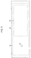
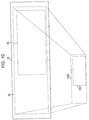
- Fig. 3 illustrates an example of a restricted area 60 of the image data 50 projected onto or displayed on the display medium 20.
- the restricted area 60 is defined on the display medium 20.
- the restricted area 60 is an area defined on the display medium in which projecting of the display information 30 included in the image data 50 is restricted.
- the display control apparatus 100 changes the configuration parameters of the restricted area 60 depending on a traffic environment, a state of the vehicle, and a state of the driver 40. More specifically, the configuration parameters of the restricted area 60 are at least one of a location, a size, a shape, and the like of the restricted area 60. This allows an increase in the degree of freedom of the location where the display information is projected, which provides improved convenience to the driver in using the display medium (for example, the HUD, the HMD or the like).
- the display medium for example, the HUD, the HMD or the like.
- the display control apparatus 100 includes an information acquisition unit 110, a judgment unit 120, and a control unit 130.
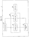
- the configuration of the display control apparatus 100 illustrated in Fig. 2 is merely an example, and the display control apparatus 100 may alternatively be configured, for example, as illustrated in Fig. 15 .
- the configuration illustrated in Fig. 2 and the configuration illustrated in Fig. 15 both include the judgment unit 120 and control unit 130 and both are similar in operations and effects.
- the information acquisition unit 110 acquires first information associated with the predetermined matter at a first time, and acquires second information associated with the predetermined matter at a second time later than the first time.
- the judgment unit 120 judges whether there is a predetermined change between the first information associated with the predetermined matter and the second information associated with the predetermined matter.
- the control unit 130 controls the image data such that the restricted area, which is an area on the display medium 20 in which projecting or displaying of display information included in the image data 50 is limited, is changed from a restricted area defined in relation to the first information associated with the predetermined matter to the restricted area defined in relation to the second information associated with the predetermined matter.
- the information acquisition unit 110 acquires information on a particular matter.
- the information on the particular matter is vehicle information including at least one of internal vehicle information and external vehicle information.
- the information acquisition unit 110 acquires vehicle information from, for example, a non-illustrated sensing camera, a driver monitoring camera, a peripheral device such as various kinds of sensors or the like, or via an in-vehicle local area network (LAN) such as a controller area network (CAN), a local interconnect network (LIN), or the like.
- LAN local area network
- CAN controller area network
- LIN local interconnect network
- the information acquisition unit 110 may acquire the vehicle information, for example, from a cloud server, or via a portable terminal such as a smartphone or the like carried in the vehicle, or via sound/voice information input by the driver, or from an information terminal installed on a traffic road or an in-vehicle terminal such as a car navigation apparatus or the like.
- the information acquisition unit 110 transmits and receives information to or from peripheral devices or the like via wired or wireless communication. Note that the information acquisition unit 110 is similar in function to the detection unit 150 in Fig. 15 . Details of the vehicle information will be described later.
- the timing for the information acquisition unit 110 to acquire the vehicle information may be controlled according to timing control data/signal actively acquired at predetermined time intervals from a peripheral device or via an in-vehicle LAN or passively received from the peripheral device or via the invehicle LAN each time the peripheral device or the in-vehicle LAN generates vehicle information.
- the information acquisition unit 110 acquires first information associated with the predetermined matter at a first time and acquires second information associated with the predetermined matter at a second time later than the first first time.
- the second time is a time at which the vehicle information is acquired after the first time.
- the second time is a time at which the vehicle information is transmitted from the peripheral device or the like after the first time. Note that from the point of view of the real-time operation of the apparatus, it is desirable that of a plurality of possible times after the first time, a time immediately after the first time is selected as the second time, although the second time is not limited to such a time but the second time may be selected according to the specifications of the apparatus.
- the vehicle information is described in further detail below.
- the internal vehicle information is information representing a state of a driver, information representing a state of a vehicle, or the like. More specifically, for example, the internal vehicle information represents an arousal level of the driver a driving mode (an automatic driving mode or a manual driving mode), an on/off state of a blinker, a vehicle speed, a measurement value output by a gyroscope, and/or the like.
- the arousal level of the driver is estimated by performing an image analysis on an image provided by a camera configured to capture an image of at least one of a face and a position of the driver.
- the automatic driving mode may be classified into levels from a first level to a fourth level or the like according to a degree to which the driver is released from the driving operation. More specifically, for example, the automatic driving mode may be classified into levels from a level-0 (no-automation) to a level-4 (full self-driving automation) according to a degree to which an automatic driving system is involved.
- external vehicle information is information representing a traffic environment or the like. More specifically, for example, the external vehicle information is information representing a road shape (straight or curved shape), a road slope, weather, a traffic signal state, or the like.
- the vehicle information includes one or more elements.
- this vehicle information includes one element "automatic driving mode".
- the vehicle information includes three elements, "manual driving mode", "left curve”, and "driver's arousal level: high”.
- the number of elements included in the vehicle information may be set according to the specifications of the apparatus.
- the elements included in the vehicle information are used by the judgment unit 120 to in making a judgment as described later. Note that the term “element” is used for convenience of explanation, and note that elements are vehicle information.
- the vehicle information acquired by the information acquisition unit 110 is output to the judgment unit 120.
- the judgment unit 120 judges whether there is a predetermined change between the first information associated with the predetermined matter (for example, vehicle information) acquired at a first time by the information acquisition unit 110 and the second information associated with the predetermined matter (for example, vehicle information) acquired at a second time later than the first time.
- first information associated with the predetermined matter for example, vehicle information
- second information associated with the predetermined matter for example, vehicle information
- the judgment on whether there is the predetermined change is performed for each of elements included in the vehicle information.
- the judgment is made only in terms of this one element.
- the concept of "element” may be meaningless.
- the judgment unit 120 judges that the predetermined change has occurred between the first vehicle information and the second vehicle information.
- the predetermined change is a specific change in the traffic environment, a specific change in the vehicle state, or a specific change in the driver's state or a combination thereof.
- the predetermined change is a change in the traffic environment, the vehicle state, or the driver's state or a combination thereof, which makes it necessary to change the configuration parameters (at least one of the location, the size, and the shape) of the restricted area 60.
- Examples of predetermined changes include a change in vehicle running state between running straight and running along a curve, a change in driving mode between a manual driving mode and an automatic driving mode, a change in automatic driving mode between different levels, a change in traffic signal state, a change in driver's arousal level, a change in road slope, a change in road shape, a change in weather, and the like.
- Examples of changes in road shape are a change in road shape between an upslope and a downslope, a change in road shape between a straight road and a T-junction, and the like. Note that the examples described above are merely some of many examples, and other changes may be defined and added to the apparatus. The adding may be realized by updating a program.
- the predetermined change may be determined based on specifications of the apparatus. For example, in a case where a change in vehicle information occurs from first vehicle information "manual driving mode, running along curve” to second vehicle information “automatic driving mode (level 4: full automatic driving), running along curve", a change occurs in driving mode and thus the judgment unit 120 may judge that there is the predetermined change. In a case where the vehicle information includes an element "automatic driving mode", even when a change occurs in another element (for example, in "running along curve”), the judgment may be performed such that there is no predetermined change. The judgment may be made according to the design specifications, the embodiment is not limited to the examples described above.
- the predetermined change associated with driver's arousal level is determined according to the specifications of the apparatus. For example, in a case where the degree of arousal are classified into five levels, extremely low, low, middle, high, and extremely high, when a change occurs from "arousal level: middle" to a "arousal level: low", the judgment may be such that there is the predetermined change, while when a change occurs from "arousal level: middle” to a "arousal level: high”, the judgment may be such that there is no predetermined change.
- the predetermined change judged by the judgment unit 120 is described in further detail below with reference to examples.
- the predetermined change is defined as a change from first vehicle information "running straight" to second vehicle information "running along left curve".
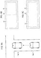
- Fig. 4A is a diagram illustrating a vehicle running on a road as seen from right above.
- Fig. 4B and Fig. 4C are diagrams illustrating a restricted area 60 of a display medium 20. Referring Figs. 4A to 4C , the first example of the predetermined change is described below.
- a vehicle is running straight at a time T1 (example of the first time) while the vehicle is running along a left curve at time T2 (example of the second time) after time T1.
- the information acquisition unit 110 acquires, at time T1, first vehicle information "running straight” indicating that the vehicle is running straight, and acquires, at time T2, second vehicle information "running along left curve” indicating that the vehicle is running along a left curve.
- the judgment unit 120 compares these two pieces of vehicle information and regards the change from "running straight” to "running along left curve” as satisfying the predetermined change and thus judges that there is the predetermined change.
- the change from a state in which a vehicle is running straight to a state in which the vehicle is running along a curve is regarded as the predetermined change because this change results in a change in range in which the driver should a visual confirmation. That is, in the situation in which the vehicle is running straight, the driver should attentively look straight ahead for the visual confirmation, and thus it is desirable that the restricted area 60 is located in front of a driver's seat as illustrated in Fig. 4B (right-hand steering wheel is assumed). On the other hand, in the situation in which the vehicle is running along a left curve, the driver should attentively look ahead of the curve, and thus it is desirable that the restricted area 60 is located on a diagonally left side ahead of the driver's seat as illustrated in Fig. 4C .
- the control unit. 130 controls the image data 50 such that the location of the restricted area 60 is changed from that illustrated in Fig. 4B to that illustrated in Fig. 4C . This makes it possible to prevent the driver's front view from blocked by display information displayed in the area that blocks the front view, while keeping the area in which it is allowed to display the display information.
- the embodiment is applicable to the case where the steering wheel is located on the left side.
- the left-side steering wheel it is judged that the predetermined change occurs when a change is detected from a running straight state to a running along right curve state. This also holds in the following description.
- the vehicle information indicating the vehicle running state may be generated based on steering information supplied via the in-vehicle LAN, map information, a sensor such as a gyroscope sensor or other sensors, image information generated by a camera configured to capture an image of an outside of the vehicle, position information such as GPS information, and/or the like.
- the vehicle information representing the vehicle running state may be judged or generated as required by a non-illustrated another constituent element.
- the judgment unit 120 may judge whether the vehicle is approaching a curve based on the image information or the navigation information, and may judge whether a predetermined change is predicted to occur.
- Fig. 5A is a diagram illustrating a vehicle rutting on a road as seen from right above.
- Fig. 5B and Fig. 5C are diagrams illustrating a restricted area 60 of the display medium 20. Referring Figs. 5A to 5C , the second example of the predetermined change is described below.
- a vehicle is running on a straight road at time T1 (example of first time) the vehicle is going to make a right or left turn at a T-junction at (example of second time) after time T1.
- the information acquisition unit 110 acquires, at time T1, first vehicle information "road: running straight” indicating that the vehicle is running on a straight road, and acquires, at time T2, second vehicle information "road: T-junction” indicating that the vehicle is going to make a right or left turn at a T-junction.
- the judgment unit 120 compares these two pieces of vehicle information and judges that the predetermined change occurs based on the fact that the change occurs from "road: running straight” to "road: T-junction".
- the change from a state in which a vehicle is running on a straight road to a state in which the vehicle is going to make a right or left turn at a T-junction is regarded as the predetermined change because this change results in a change in range that is supposed to be attentively looked at for the visual confirmation by the driver. That is, in the situation in which the vehicle is running on a straight road, the driver attentively looks straight ahead and recognizes the side state by looking aside, and thus it is desirable that the restricted area 60 is located in front of the driver's seat as illustrated in Fig. 5B (in the case where the steering wheel is located on the right side).
- the restricted area 60 is set such that its horizontal width is substantially equal to the horizontal width of the display medium 20 as illustrated in Fig. 5C .
- the control unit 130 controls the image data 50 such that the location of the restricted area 60 is changed from that illustrated in Fig. 5B to that illustrated in Fig. 5C . This makes it possible, in the situation in which a right or left turn is going to be made, to prevent the front view from being blocked by display information displayed in a viewing direction, while ensuring that the display medium 20 has an area in which it is allowed to display display information.
- the vehicle information representing the traffic environment in which the vehicle is running may be generated based on steering information supplied via the in-vehicle LAN, map information, a sensor such as a gyroscope sensor or other sensors, image information generated by a camera configured to capture an image of the outside of the vehicle, or position information such as GPS information, and/or the like.
- the vehicle information representing the vehicle running state may be judged or generated as required by a non-illustrated another constituent element.
- the judgment unit 120 may recognize a stop sign, a stop line, or the like from the image information and may make a judgment on the occurrence of the predetermined change based on a recognition result.
- the predetermined change may be defined as a change from a state in which "no sign is detected" to a state in which "a sign is detected".
- the predetermined change occurs when a right or left turn is going to be made at a T-junction.
- a blinker operation left turn/right turn
- the predetermined change may be defined as a change in state from "there is no blinker operation" to "there is a blinker operation”. This makes it possible to detect the predetermined change when a right or left is going to be made even at a place other than a T-junction, and it is allowed to change the restricted area 60 in response to detecting the predetermined change.
- it may be allowed to detect a state in which the vehicle is approaching a T-junction or an intersection, and a judgment may be made as to whether a predetermined change is going to occur.
- the predetermined change is defined as a change from first vehicle information "signal: red” to second vehicle information "signal: blue”.
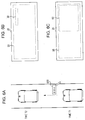
- Fig. 6A is a diagram illustrating a vehicle rutting on a road as seen from right above.
- Fig. 6B and Fig. 6C are diagrams illustrating a restricted area 60 of a display medium 20. Referring Figs. 6A to 6C , the third example of the predetermined change is described below.
- a vehicle is in a stop state at a red signal of a traffic signal 600 at time T1 (example of first time) and the vehicle starts to run in response to a change in the state of the traffic signal 600 from red to blue at time T2 (example of second time) after time T1.
- the information acquisition unit 110 acquires, at time T1, first vehicle information "signal: red” indicating that the traffic signal 600 is in the red state, and acquires, at time T2, second vehicle information "signal: blue” indicating that the traffic signal 600 is in the blue state.
- the judgment unit 120 compares these two pieces of vehicle information and detects the change in vehicle information from "signal: red” to "signal: blue", and thus the judgment unit 120 judges that the predetermined change has occurred.
- the change from the red signal to the blue signal is regarded as the predetermined change, because this change in the state results in a change in the range that should be attentively looked at by the driver. That is, when the traffic signal 600 is in the red state, the driver is released from driving the vehicle, and thus the restricted area 60 is allowed to be located in a small area directly ahead of the driver's seat as illustrated in Fig. 6B . On the other hand, when the traffic signal 600 changes from the red state to the blue state, the driver needs to start driving the vehicle, and thus it is desirable that the restricted area 60 is located in a large area directly ahead of the driver's seat as illustrated in Fig. 6C .
- the control unit 130 controls the image data 50 such that the location of the restricted area 60 is changed from that illustrated in Fig. 6B to that illustrated in Fig. 6C .
- the control unit 130 controls the image data 50 such that the location of the restricted area 60 is changed from that illustrated in Fig. 6B to that illustrated in Fig. 6C .
- the vehicle information representing the change in the state of the traffic traffic signal 600 may be generated based on image information generated by a camera configured to capture an image of the outside of the vehicle, information transmitted from an information terminal installed at an intersection, information transmitted from a cloud server, or the like.
- the vehicle information representing the change in the state of the traffic traffic signal 600 may be judged or generated as required by a non-illustrated another constituent element.
- the restriction area 60 may be controlled in response to a change in the state of a signal for pedestrians.
- the change in the state of the signal for pedestrians from blue to red is regarded as the predetermined change.
- the area of the restricted area 60 is changed from that illustrated in Fig. 6B to that illustrated in Fig. 6C .
- the predetermined change is defined as a change from first vehicle information "manual driving mode" to second vehicle information "automatic driving mode”.
- Fig. 7A is a diagram illustrating a vehicle rutting on a road as seen from right above.
- Fig. 7B and Fig. 7C are diagrams illustrating a restricted area 60 of the display medium 20. Referring Figs. 7A to 7C , the fourth example of the predetermined change is described below.
- the automatic driving mode is classified into five automatic driving levels according to a degree to which the automatic driving system is involved with the driving, and more specifically, the automatic driving level is classified into levels from level 0 (no-automation) to level 4 (full self-driving automation).
- the automatic driving level is classified into levels from level 0 (no-automation) to level 4 (full self-driving automation).
- the explanation is given by way of example for a case where the automatic driving mode is in level 4 (full self-driving automation).
- a vehicle is running under a manual control by a driver at time T1 (example of first time), and the vehicle is running in the full self-driving automation mode at time T2 (example of second time) after time T1.
- the information acquisition unit 110 acquires, at time T1, first vehicle information "manual driving mode" indicating that the vehicle is running in the manual driving mode, and acquires, at time T2, second vehicle information indicating that the vehicle is running in the automatic driving mode.
- the judgment unit 120 compares these two pieces of vehicle information and judges that there is the predetermined change by regarding the change from "manual driving mode" to "automatic driving mode” as the predetermined change.
- the change from the manual driving mode to the automatic driving mode is regarded as the predetermined change because this change in the state results in a change in the range that should be attentively looked at by the driver. That is, in the situation in which the vehicle is driven in the manual driving mode, the driver needs to attentively look ahead and thus the restricted area 60 is set in an area directly ahead of the driver's seat as illustrated in Fig. 7B . On the other hand, in the full automatic driving mode, the driver is released from driving the vehicle, and thus, as illustrated in Fig. 7C , the restricted area 60 is not necessary.
- the control unit 130 controls the image data 50 such that the restricted area 60 displayed in the manner,as illustrated in Fig. 7B is deleted as illustrated in Fig. 7C . This allows an increase in degree of freedom associated with the location of the display information when the vehicle is driven in the automatic driving mode.
- the vehicle information representing the vehicle driving mode may be generated based on information acquired via the in-vehicle LAN or the like.
- the vehicle information representing the vehicle driving mode may be judged or generated as required by a non-illustrated another constituent element.
- the predetermined change is defined as a change from first vehicle information "driver's arousal level: high" to second vehicle information "driver's arousal level: low”.
- Fig. 8A is a diagram illustrating a manner in which a driver drives a vehicle.
- Fig. 8C and Fig. 8C are diagrams illustrating a restricted area 60 of a display medium 20. Referring Figs. 8A to 8C , the fifth example of the predetermined change is described below.
- the driver is in a high arousal level at time T1 (example of first time), and, at time T2 (example of second time), the driver is in an arousal level lower than the arousal level at time T1.
- the information acquisition unit 110 acquires, at time T1, first vehicle information "driver's arousal level: high” indicating that the driver in the high arousal level, and acquires, at time T2, second vehicle information "driver's arousal level: low” indicating that the driver in the low arousal level.
- the judgment unit 120 compares these two pieces of vehicle information and regards the change in driver arousal level from "high” to "low” as the predetermined change and thus judges that there is the predetermined change.
- the change in driver's arousal level from a high state to a low state is regarded as the predetermined change for the following reason.
- the control unit 130 controls the image data 50 such that the restricted area 60 illustrated in Fig. 8B is expanded as illustrated in Fig. 8C . This allows it to prevent the driver's watching from being concentrated on a distant point, and it becomes possible to prompt the driver to make a visual confirmation on safety over a wide range.
- the vehicle information representing the driver's arousal level may be acquired, for example, by detecting the open level of an eyelid from an image of the driver captured by a driver monitoring camera and estimating the arousal level based on the detected open level of the eyelid.
- the arousal level may be estimated by detecting the open level of the eyelid determined by analyzing an electric signal output from an electrode attached to a head of the driver at a point close to a tail of the eye.
- the judgment unit 120 judges that a predetermined change has occurred, the judgment unit 120 outputs information to the control unit 130 to notify that the predetermined change has occurred.
- the control unit 130 controls the image data such that the restricted area 60 of the display medium 20 is changed from the restricted area defined in relation to the first information associated with the predetermined matter to the restricted area defined in relation to the second information associated with the predetermined matter. That is, the control unit 130 controls the image data 50 such that the configuration parameters (at least one of the location, the size, and the shape) of the restricted area 60 is changed from the configuration parameters defined in relation to the first vehicle information to that defined in relation to the second vehicle information, that is, at least one of the location, the size, and the shape defined in relation to the first vehicle information is changed to that defined in relation to the second vehicle information.
- the control unit 130 controls the display unit 200 such that a predetermined image representing an image 30 indicating notification information is generated and displayed on the display medium in an area outside a second restricted area (i.e., in the area which is outside the second restricted area and in which it is allowed to display information) which is defined in advance in relation to a second predetermined state and which is different from a first restricted area in terms of at least one of the location, the size, the number, and the shape.
- a second restricted area i.e., in the area which is outside the second restricted area and in which it is allowed to display information
- control unit 130 is described in further detail below. First, when the control unit 130 receives, from the judgment unit 120, information indicating that a predetermined change has occurred, the control unit 130 acquires at least the second vehicle information from the judgment unit 120. Note that the control unit 130 may acquire the first vehicle information together with the second vehicle information from the judgment unit 120.
- the control unit 130 controls the image data 50 such that at least one of the location, the size, and the shape of the current restricted area 60 (that is, at least one of the location, the size, and the shape defined in relation to the first vehicle information) is changed to at least corresponding one of the location, the size, and the shape defined in relation to the second vehicle information.
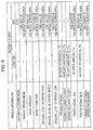
- the vehicle information are related in advance to the location, the size, and the shape of the restricted area 60 and stored in a storage apparatus (for example, see Fig. 14 ). An example of correspondence between the vehicle information and the location, the size, and the shape of the restricted area 60 will be described later with reference to Fig. 9 .
- the storage apparatus may in installed in a server apparatus (not illustrated) capable of communicating with the system 1.
- Fig. 9 illustrates an example of a table defining the correspondence between vehicle information and the location and the size (the shape is not illustrated herein) of the restricted area 60.
- the location of the restricted area 60 is defined, for example, by coordinates of the center of the restricted area 60
- the location of the restricted area 60 may be defined by any reference point of the restricted area 60 (for example, a point in the upper left corner of the restricted area 60), and the scope of the present embodiment is not limited to the examples described above.
- vehicle information "automatic driving mode” is set to "zero" for the size of the restricted area 60 (that is, the restricted area 60 is not defined).
- vehicle information "manual driving mode” is related to the restricted area 60 having a size of "one-half of the whole screen area”.
- the whole screen area is, for example, the whole area of image data 50.
- the whole screen area may be the whole area of the display medium 20.
- the location of the restricted area 60 is not defined (in the table, each dash is used to express that there is no definition), but the location of the restricted area 60 may alternatively be defined, for example, as "area directly in front (X 1 , Y 1 )".
- Fig. 9 for example, vehicle information "road: running straight” is set to have a size of "one-half of the total screen area” as the size of the restricted area 60.
- vehicle information “road: T-junction” is set to have a size of "two-thirds the total screen area” as the size of the restricted area 60.
- the location of the restricted area 60 is not defined.
- vehicle information "driver's arousal level: high” and vehicle information “driver's arousal level: middle” are each set to have a size of "one-half of the total screen area” as the size of the restricted area 60.
- vehicle information "driver's arousal level: low” is set to have a size of "two-thirds the total screen area” as the size of the restricted area 60.
- the location of the restricted area 60 is not defined.
- Fig. 9 for example, for vehicle information "running straight”, the location of the restricted area 60 is defined as "area directly in front (X 1 , Y 1 )". On the other hand, for vehicle information "running along right curve”, the location of the restricted area 60 is defined as “right side: coordinates (X R , Y R )", and for vehicle information “running along left curve” the location of the restricted area 60 is defined as "left side: coordinates (X L , Y L )".
- the size of the restricted area 60 is not defined, although the size of the restricted area 60 may be alternatively defined, for example, as "one-half of the total screen area".
- the location of the restricted area 60 may be defined such that the location varies depending on the degree of a curve (curvature).
- Fig. 9 for example, for vehicle information "signal: red”, the location of the restricted area 60 is defined as “upper side (X U , Y U )", and the size of the restricted area 60 is defined as “one-sixth of the whole screen area”.
- vehicle information “signal: blue” the location of the restricted area 60 is defined as "area directly in front (X 2 , Y 2 )", and the size of the restricted area 60 is defined as "one-half of the whole screen area”. In any of these cases, the location and the size of the restricted area are defined.
- Fig. 9 for example, for vehicle information "right turn/left turn (blinker operated)", the size of the restricted area 60 is defined as "two-thirds of the whole screen area", and the location of the restricted area 60 is not defined.
- the restricted area 60 is defined for each piece of vehicle information such that only the location of the restricted area 60, or only the size of the restricted area 60, or both the location and the size of the restricted area 60 are defined depending on the vehicle information. Note that the definition is made according to the design specifications of the apparatus, and the scope of the present embodiment is not limited by these examples.
- the control unit 130 controls the image data 50 so as to change at least one of the location, the size, and the shape of the restricted area 60 according to the table illustrated in Fig. 9 . That is, the control unit 130 generates the image data 50 such that display information 30 is not included in the restricted area 60.
- the control unit 130 controls the image data 50 based on a combination of the location and/or the size of the restricted area 60 related to the plurality of elements.
- the controlling performed by the control unit 130 is described in further detail below with reference to specific examples. In the following examples, fur convenience of explanation, it is assumed by way of example that the control is performed based on the table illustrated in Fig. 9 , and only the location and the size of the restricted area 60 are taken into account in the control.
- the control unit 130 controls the image data 50 such that the location of the restricted area 60 is set at "area directly in front (X 1 , Y 1 )", and the size is set to "one-half of the whole screen size".
- a change occurs after that from the first vehicle information to second vehicle information indicating that "manual driving mode, running along right curve". In this case, a change occurs in one of the two elements of the vehicle information.
- the control unit 130 controls the image data 50 such that the location of the restricted area 60 is changed to "right side: coordinates (X R , Y R )", while the size of the restricted area 60 is maintained at "one-half of the whole screen area”.
- the control unit 130 controls the image data 50 such that the location of the restricted area 60 is set at "area directly in front (X 1 , Y 1 )", and the size is set to "one-half of the whole screen size".
- a change occurs after that from the first vehicle information to second vehicle information indicating that "automatic driving mode, running along left curve". In this case, a change occurs in both of the two elements of the vehicle information.
- the control unit 130 controls the image data 50 such that the location of the restricted area 60 is changed to "left side: coordinates (X L , Y L )", and the size of the restricted area 60 is changed to "zero".
- the design specifications may be set such that controlling is not performed in terms of the other elements.
- the control unit 130 controls the image data 50 such that the location of the restricted area 60 is set at "area directly in front (X 2 , Y 2 )", and the size is set to "one-half of the whole screen size".
- a change occurs after that from the first vehicle information to second vehicle information indicating that "manual driving mode, road: T-junction, signal: red".
- the control unit 130 controls the image data 50 such that the location of the restricted area 60 is changed to "upper side (X U , Y U )".
- the "one-half of the whole screen area” is assigned to the "manual driving mode”
- the "two-thirds of the whole screen area” is assigned to the "road: T-junction”
- the "one-sixth of the whole screen area” is assigned to the “signal: red”.
- the determination as to which location and which size are employed depends on the design specifications, and the scope of the present embodiment is not limited thereto. From the point of view of safe vehicle driving, it is desirable to select a location and a size that provide the highest safety. Thus, in the above example, it is desirable to select the "two-thirds of the whole screen area" assigned to the "road: T-junction" as the size of the restricted area 60.
- control unit 130 controls not only the restricted area 60 but also, for example, the display information 30 (for example, character information such as warning information, navigation information, entertainment information, and/or the like) included in the image data 50. More specifically, the control unit 130 controls the location, the size, the range, the brightness, the color, and/or transparency of the display information 30 included in the image data 50.
- the display information 30 for example, character information such as warning information, navigation information, entertainment information, and/or the like
- the control unit 130 controls the location, the size, the range, the brightness, the color, and/or transparency of the display information 30 included in the image data 50.
- a calibration is performed in advance on the restricted area 60 defined on the display medium 20 and an area corresponding to the restricted area 60 defined on image data 1000.
- the image data 1000 refers to image data which is not yet projected onto the display medium 20. That is, as illustrated in Fig. 10 , a calibration is performed in advance on the restricted area 60 defined on the display medium 20 and an area 1001 corresponding to the restricted area 60 defined on image data 1000.
- a method of defining of the correspondence between the restricted area 60 and the area 1001, and a method of performing the calibration are known, and thus a further description thereof is omitted.
- the shape of the restricted area 60 is rectangular.
- the shape is not limited to the rectangle, and the shape of the restricted area 60 may be circular, elliptic, or any other shapes.
- the shape of the restricted area 60 may be defined in the table in Fig. 9 for each piece of vehicle information.
- the control unit 130 may control the image data 50 such that the restricted area 60 is changed only in terms of the shape or together with the location and/or the size.
- the control unit 130 controls the image data 50 such that the shape (for example, the rectangle) assigned to the restricted area 60 corresponding to the first vehicle information is changed to a shape (for example, an ellipse) assigned to the restricted area 60 corresponding to the second vehicle information.
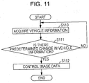
- the configuration of the display control apparatus 100 according to the present embodiment has been described above. Next, an example of an operation of the display control apparatus 100 is described below with reference to a flow chart illustrated in Fig. 11 .
- step S110 the information acquisition unit 110 acquires the first vehicle information at first time (for example, at time T1 described above), acquires the second vehicle information at second time (for example, at time T2 described above) later than the first time.
- step S111 the judgment unit 120 judges whether there is a predetermined change (for example, one of the first to fifth examples of changes described above) between the first vehicle information and the second vehicle information. In a case where the judgment indicates that there is no predetermined change (the answer to step S111 is No), the processing flow returns to step S110. On the other hand, in a case where the judgment indicates that there is a predetermined change (the answer to step S111 is Yes), the processing flow proceeds to step S112.
- a predetermined change for example, one of the first to fifth examples of changes described above
- step S112 the control unit 130 controls the image data 50 such that at least one of the location, the size, and the shape of the restricted area 60 which is an area of the display medium 20 in which projecting of the display information 30 included in the image data 50. That is, the control unit 130 controls the image data 50 such that at least one of the location, the size, and the shape of the restricted area 60 assigned to the first vehicle information is changed to at least one of the location, the size, and the shape of the restricted area 60 assigned to the second vehicle information.
- the display control apparatus 100 As described above, in the display control apparatus 100 according to the present embodiment, a judgment is performed as to whether there is a predetermined change in time-series vehicle information acquired, and if a predetermined change is found, at least one of the location, the size, and the shape of the restricted area 60 defined in advance in relation to first vehicle information acquired at a previous time is changed to at least one of the location, the size, and the shape of the restricted area 60 defined in advance in relation to second vehicle information acquired at a later time.
- the display control apparatus 100 is capable of, depending on the situation, preventing the user's front view from being blocked while keeping an area in which information is displayed.
- a display control system 2 may include an acquisition unit 140, a detection unit 150, a display control apparatus 1500, and a display unit 200, and a display control apparatus 1500 may include a judgment unit 120 and a control unit 130.
- the detection unit 150 is similar in function to the information acquisition unit 110 as described above.
- the acquisition unit 140 is configured to acquire notification information to be notified to a driver 40 of a vehicle
- the detection unit 150 is configured to detect a predetermined state of at least one of the vehicle and the driver 40
- the display unit 200 is configured to generate a predetermined image (image data) based on the notification information acquired via the acquisition unit 140 and project the predetermined image (image data) onto the display medium 20, and the display control apparatus 1500 is connected to the units described above.
- the control unit 130 controls the display unit 200 such that when the predetermined image is displayed on the display medium 20, the predetermined image is generated so as to represent an image 30 indicating the notification information and is projected onto the display medium 20 such that the image 30 is displayed in an area other than a first restricted area 60, of the display medium 20, defined in advance in relation to the first predetermined state.
- the judgment unit 120 judges whether there is a predetermined change between the first predetermined state and the second predetermined state.
- the control unit 130 controls the display unit 200 such that when the predetermined image is displayed on the display medium 20, the predetermined image is generated so as to represent an image 30 indicating the notification information and is projected onto the display medium 20 such that the image 30 is displayed in an area other than a second restricted area 60 defined in advance in relation to the second predetermined state and being different from the first restricted area 60 in terms of at least one of the location, the size, the number, and the shape.
- the restricted area 60 is an area of the display medium 20 in which displaying of notification information is limited
- the other area of the display medium 20 other than the restricted area is an area (allowed area) outside the restricted area 60 in which displaying of notification information is allowed.
- the acquisition unit 140 acquires notification information to be notified to a driver 40 of a vehicle.
- the notification information is display information 30 to be presented to the driver 40 of the vehicle. That is, the notification information is part of the image data 50 and is viewed as a virtual image by the driver 40.
- the notification information is, for example, a message indicating a warning of a possible collision with a vehicle ahead, a message calling attention to a pedestrian ahead, entertainment information, vehicle information associated with a speed of the vehicle or the like, a AR display on an obstacle located ahead or a destination or the like, navigation information, and/or the like.
- the notification information may be given in the form of a graphical image, a character, a symbol, or a combination thereof.
- the detection unit 150 detects a predetermined state of at least one of the vehicle and the driver 40. Note that the detection unit 150 has a function similar to that of the information acquisition unit 110.
- the control unit 130 controls the display unit 200 such that the predetermined image is generated so as to represent the image 30 indicating the notification information and is projected onto the display medium 20 (not illustrated).
- the notification information is recognized by the driver 40 as a virtual image displayed in an area other than the first restricted area 60 which is an area, on the display medium 20, defined in advance in relation to the first predetermined state.
- the control unit 130 controls the display unit 200 such that the predetermined image is generated so as to represent an image 30 indicating the notification information and is projected,onto the display medium 20 such that the image 30 is displayed in an area other than a second restricted area 60 defined in advance in relation to the second predetermined state and being different from the first restricted area 60 in terms of at least one of the location, the size, the number, and the shape.
- the control unit 130 has been described in detail above.
- the judgment unit 120 judges whether there is a predetermined change between the first predetermined state and the second predetermined state.
- the judgment unit 120 judges that a predetermined change has occurred, the judgment unit 120 outputs information to the control unit 130 to notify that the predetermined change has occurred.
- the predetermined change is a specific change in the traffic environment, a specific change in the vehicle state, or a specific change in the driver's state, or a combination thereof. That is, the predetermined change is a change in the traffic environment, the vehicle state, or the driver's state or a combination thereof in response to which it is necessary to change the configuration parameters of the restricted area 60.
- control unit 130 may control the display unit 200 such that the predetermined image is generated and projected onto the display medium 20 such that the image 30 representing the first notification information is moved from the second restricted area 60 into an area other than the second restricted area 60.
- the judgment unit 120 judges whether there is a predetermined change between the second predetermined state and the third predetermined state.
- the control unit 130 may control the display unit 200 such that the predetermined image is generated so as to represent an image 30 indicating the first notification information and is projected onto the display medium 20 such that the image 30 is displayed in an area other than the third restricted area 60 defined in advance in relation to the third predetermined state and being different from the second restricted area 60 in terms of at least one of the location, the size, the number, and the shape.
- control unit 130 may control the display unit 200 such that the predetermined image is generated so as to represent the image 30 indicating the first notification information and is projected onto the display medium 20 such that the image 30 is displayed at the location where the image 30 indicating the first notification information was displayed at the first time.
- control unit 130 may control the display unit 200 such that the predetermined image is generated and displayed onto the display medium 20 such that the image 30 representing the first notification information is not displayed on the display medium 20.
- control unit 130 may control the display unit 200 such that the predetermined image is generated so as to represent an image 30 representing the first notification information and an image 30 representing the second notification information and is projected onto the display medium 20 such that the image 30 representing the first notification information and the image 30 representing the second notification information are displayed in an area other than the first restricted area.
- control unit 130 may control the display unit 200 such that the predetermined image is generated so as to represent the image 30 indicating the first notification information and the image 30 indicating the second notification information and is projected onto the display medium 20 such that the image 30 indicating the first notification information is displayed in an area other than the second restricted area 60 and the image 30 indicating the second notification information is displayed at the location where the image 30 indicating the second notification information was displayed at the first time.
- control unit 130 may control the display unit 200 such that the predetermined image is generates so as to represent the image 30 indicating the second notification information changed in terms of at least one of the color, the transparency, and the luminance, and the generated predetermined image is displayed on the display medium 20 such that the image 30 is displayed at the locate where the image 30 indicating the second notification information was displayed at the first time.
- the predetermined state indicates an automatic driving level of the vehicle, and the automatic driving level is one of a plurality of prescribed levels from a level in which all operations necessary in driving are performed by a driver of a vehicle to a level in which automatic driving is performed without the driver of the vehicle having to perform any operation necessary in driving.
- the predetermined change between the first automatic driving level and the second automatic driving level may be a change between levels in the plurality of levels.
- the edge of the restricted area 60 may be indicated with a solid line, a dotted line, a broken line, a chain line, or a wavy line, projected onto the display medium 20.
- the display control system 20 has been described in detail above.
- the information acquisition unit 110 acquires information about a situation ahead of the walking user.
- the determination unit compares the first information associated with the predetermined matter acquired at first time and the second information associated with the predetermined matter acquired at second time.
- the information on a particular matter is, for example, the information about the situation ahead of the walking user.
- the control unit 130 controls the image data such that the configuration parameters of the restricted area 60 on the glasses-type display medium is changed.
- the predetermined change in the case where the glasses-type display medium is used is, for example, a change that occurs when a bicycle is approaching the user from the forward direction at a speed equal to or higher than a predetermined value, a change that occurs when another person is approaching the user from the forward direction, which may result in a collision.
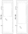
- the control unit 130 controls the image data 50 such that the display information 30 is projected in an area outside the changed restricted area 60.
- the restricted area 60 is expanded from that illustrated in Fig. 12A to that illustrated in Fig. 12B
- the display information 30 is included in the restricted area 60 in Fig. 12B , which causes the front view of the driver 40 to be blocked.
- the control unit 130 controls the image data 50 such that in response to expanding of the restricted area 60 from the state illustrated in Fig. 12A , the display information 30 is pushed in the expanding direction (to the left in the example illustrated in Fig. 12B ) by the expanding restricted area 60 (hereinafter, this is referred to as "moving controls").
- the pushed display information 30 is displayed in an area outside the restricted area 60.
- the direction in which the display information 30 is pushed is not limited to the direction in which the restricted area 60 is expanded.
- the size of the restricted area 60 is expanded. The control may be performed in a similar manner also in a case where the location or the shape of the restricted area 60 is changed.
- This example of mediation described below is associated with an operation performed following the move control in the first example of modification.
- the control unit 130 controls the image data 50 such that the display information 30 projected in the area outside the changed restricted area 60 is returned to the projection position assigned to the third vehicle information (that is, to the original projection position assigned to the first vehicle information).
- the third time is a timing later than the second time. That is, when the third vehicle information is acquired in the state illustrated in Fig. 12B , the control unit 130 returns the restricted area 60 and the display information 30 to the state illustrated in Fig. 12B to the state illustrated in Fig. 12A .
- controlling is performed such that the display information 30 is not projected (hereinafter, referred to as deleting control). That is, in a case where when the restricted area 60 is changed from that assigned to the first vehicle information to that assigned to the second vehicle information, if the display information 30 falls within the changed restricted area 60, the control unit 130 controls the image data 50 such that the display information 30 projected on the display medium 20 is deleted. Note that in a case where after the display information 30 is deleted, if the third vehicle information described above is acquired, then the control described in the second example of modification may be performed.
- the outline of the restricted area 60 may be projected such that the outline is visible by the driver 40.
- the outline of the restricted area 60 may be indicated with a solid line, a dotted line, a broken line, a chain line, or a wavy line.
- the display information to be subjected to the moving control in the first example of medication or the deleting control in the third example of medication may be classified according to its attribute.
- classes of the display information are defined in advance according to types of the display information as follows. Display information to be subjected to the moving control is classified into a first type, and display information not to be subjected to the moving control is classified into a second type. Examples of the first type display information include entertainment information, navigation information, and other information which is not urgent. Examples of the second type display information include warning information, alarm information, and other urgent information.
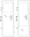
- Fig. 13A illustrates an example of a manner in which display information is displayed on the display medium 20 when the first vehicle information is acquired.
- display information 30 and display information 31 are projected in an area outside the restricted area 60.
- the display information 30 is information of the first type
- the display information 31 is information of the second type.
- the control unit 130 controls the restricted area 60 so as to expand it to the left.
- the display information 30 and the display information 31 are included in the expanded restricted area 60, and thus the control unit 130 determines whether the display information 30 and the display information 31 being projected are respectively of the first type or the second type.
- the display information 30 is determined as being of the first type, and thus the control unit 130 performs the moving control on the display information 30. As a result, the display information 30 is pushed in the direction in which the restricted area 60 is expanded in the manner as described in the first example of modification such that the display information 30 is projected in an area outside the restricted area 60 as illustrated in Fig. 13B .
- the display information 31 is determined as being of the second type, and thus the control unit 130 does not perform the moving control on the display information 31. As a result, the display information 31 remains within the restricted area 60 as illustrated in Fig. 13B .
- the criterion for classifying the display information 30 is not limited to the type of information.
- the display information 30 may be classified according to attributes such as color, brightness, or the like that attract an attention of the driver.
- control unit 130 may control the image data 50 such that at least one of the color, the transparency, and the luminance of the display information 30 is changed.
- the control unit 130 may control the image data 50 such that the restricted area 60 is divided into a plurality of sub-areas. For example, in a case where a change occurs from the first vehicle information "signal: blue" to the second vehicle information "signal: red", the control unit 130 may divide the restricted area 60 located immediately ahead of the driver 40 into two parts on right and left sides of the display medium 20 while maintaining the total area unchanged.
- the control unit 130 may set control parameters such as a speed of moving the display information 30 (a speed at which the display information moves), a response speed (timing of starting moving the display information), and/or the like based on correlation in location or size of the restricted area between before and after the occurrence of the change of the restricted area. More specifically, the relative size of the restricted area is increased, for example, when a situation occurs in which the driver 40 should pay attention to the surrounding environment as in a case in which the vehicle is approaching a curve or a T-junction. Thus the speed of moving the display information is set to be high or the response speed is set to be short.
- control parameters such as a speed of moving the display information 30 (a speed at which the display information moves), a response speed (timing of starting moving the display information), and/or the like based on correlation in location or size of the restricted area between before and after the occurrence of the change of the restricted area. More specifically, the relative size of the restricted area is increased, for example, when a situation occurs in which the driver 40 should pay attention to
- the relative size of the restricted area is reduced, for example, when the situation where the driver should pay attention is over as is the case where a curve or a T-junction has been passed through. If the display information 30 is moved quickly or in a short response time in such a situation, this will annoy the driver. Therefore, when the relative size of the restricted area is reduced, the display information 30 is moved slowly or in a long response time, which makes it possible to control the display information without annoying the driver 40 with the quick motion.
- Fig. 14 illustrates a hardware configuration of a computer capable of providing various functions of the display control apparatus 100 by executing a program.
- the computer 1000 includes an input apparatus 1001 such as a keyboard, mouse, a touch pad, or the like, an output apparatus 1002 such as a display medium 20, a speaker, or the like, a central processing unit (CPU) 1003, a read only memory (ROM) 1004, a random access memory (RAM) 1005, a storage apparatus 1006 such as a hard disk apparatus, a solid state drive (SSD), or the like, a reading unit 1007 configured to read information from a storage medium such as an a digital versatile disk read only memory (DVD-ROM), an universal serial bus (USB) memory, or the like, and a transmission/reception apparatus 1008 configured to perform communication via a network.
- the above-described apparatuses/units are connected to each other via a bus 1009.
- the reading unit 1007 reads the program, that allows it to realize the above-described various functions of the display control apparatus, from the storage medium and stores the read program in the storage apparatus 1006.
- the transmission/reception apparatus 1008 may download the program, that allows it to realize the above-described various functions of the display control apparatus, from a server by performing communication with the server connected to the network, and the downloaded program may be stored in the storage apparatus 1006.
- the CPU 1003 copies the program from the storage apparatus 1006 into the RAM 1005, and sequentially reads and executes instructions included in the program copied in the RAM 1005 thereby realizing the various functions of the display control apparatus.
- information acquired in various processes described above in the embodiments is stored in the RAM 1305 and/or the storage apparatus 1306 and the information is used as necessary.
- the present disclosure is useful to realize the display control apparatus capable of controlling displaying of information provided to a user (such as a driver of a vehicle, a user wearing a displaying device, or the like), the display control method, the display control program, and the projection apparatus.
Landscapes
- Engineering & Computer Science (AREA)
- Physics & Mathematics (AREA)
- General Physics & Mathematics (AREA)
- Computer Hardware Design (AREA)
- Theoretical Computer Science (AREA)
- Optics & Photonics (AREA)
- Multimedia (AREA)
- Software Systems (AREA)
- General Engineering & Computer Science (AREA)
- Signal Processing (AREA)
- Computer Graphics (AREA)
- Mechanical Engineering (AREA)
- Instrument Panels (AREA)
- Transforming Electric Information Into Light Information (AREA)
- Controls And Circuits For Display Device (AREA)
- Traffic Control Systems (AREA)
- User Interface Of Digital Computer (AREA)
Claims (12)
- Anzeigesteuerungsvorrichtung (100) in einem Anzeigesystem mit einer Erfassungseinheit (110), die ausgebildet ist, eine erste Benachrichtigungsinformation, die einem Fahrer eines Fahrzeugs bekannt zu geben ist, zu erfassen, mit einer Detektiereinheit (150), die ausgebildet ist, einen vorbestimmten Zustand des Fahrzeugs oder des Fahrers zu detektieren, und mit einer Anzeigeeinheit (200), die ausgebildet ist, ein vorbestimmtes Bild auf der Grundlage der ersten Benachrichtigungsinformation, die mittels der Erfassungseinheit erfasst wurde, zu erzeugen, wobei die Anzeigesteuerungsvorrichtung umfasst:eine Steuerungseinheit (130), die ausgebildet ist, die Anzeigeeinheit (200) so zu steuern, dass, wenn die die Detektiereinheit (150) einen ersten vorbestimmten Zustand an einem ersten Zeitpunkt (T1) detektiert, ein erstes vorbestimmtes Bild zur Darstellung der ersten Benachrichtigungsinformation erzeugt und auf einem Anzeigemedium (20) derart angezeigt wird, dass das erste vorbestimmte Bild in einem Bereich auf dem Anzeigemedium (20) außerhalb eines ersten begrenzten Bereichs (60) angezeigt wird, der im Voraus in Verbindung mit dem ersten vorbestimmten Zustand festgelegt ist; undeine Bestimmungseinheit (120), die ausgebildet ist, eine Bewertung vorzunehmen derart, dass, wenn die die Detektiereinheit (150) einen zweiten vorbestimmten Zustand, der sich von dem ersten vorbestimmten Zustand unterscheidet, an einem zweiten Zeitpunkt (T2), der später als der erste Zeitpunkt (T1) ist, detektiert, die Bestimmungseinheit (120) bewertet, ob es eine vorbestimmte Änderung zwischen dem ersten vorbestimmten Zustand und dem zweiten vorbestimmten Zustand gibt,wobei, wenn die Bestimmungseinheit (120) bewertet, dass es eine vorbestimmte Änderung gibt, die Steuerungseinheit (130) die Anzeigeeinheit (200) derart steuert, dass ein zweites vorbestimmtes Bild zur Darstellung der ersten Benachrichtigungsinformation erzeugt und auf dem Anzeigemedium (20) so angezeigt wird, dass das zweite vorbestimmte Bild in einem Bereich außerhalb eines zweiten begrenzten Bereichs (60) auf dem Anzeigemedium (20) angezeigt wird, der im Voraus in Verbindung mit dem zweiten vorbestimmten Zustand festgelegt ist, und wobei der zweite begrenzte Bereich (60) sich von dem ersten begrenzten Bereich (60) in Position, Größe, Anzahl und/oder Form unterscheidet.
- Verfahren für ein Anzeigesystem, das eine Erfassungseinheit (110), die ausgebildet ist, eine erste Benachrichtigungsinformation, die einem Fahrer eines Fahrzeugs bekanntzugeben ist, zu erfassen, eine Detektiereinheit (150), die ausgebildet ist, einen vorbestimmten Zustand des Fahrzeugs und/oder des Fahrers zu detektieren, und eine Anzeigeeinheit (200) aufweist, die ausgebildet ist, ein vorbestimmtes Bild auf der Grundlage der ersten Benachrichtigungsinformation, die über die Erfassungseinheit erfasst wird, zu erzeugen, wobei das Verfahren die Schritte umfasst
Steuern der Anzeigeeinheit (200) derart, dass, wenn die die Detektiereinheit (150) einen ersten vorbestimmten Zustand an einem ersten Zeitpunkt (T1) detektiert, ein erstes vorbestimmtes Bild zur Darstellung der ersten Benachrichtigungsinformation erzeugt und auf dem Anzeigemedium (20) derart angezeigt wird, dass das erste vorbestimmte Bild in einem Bereich außerhalb eines ersten begrenzten Bereichs (60) angezeigt wird, der im Voraus in Verbindung mit dem ersten vorbestimmten Zustand festgelegt wird;
Vornehmen einer Bewertung derart, dass, wenn die die Detektiereinheit (150) einen zweiten vorbestimmten Zustand, der sich von dem ersten vorbestimmten Zustand unterscheidet, an einem Zeitpunkt (T2) detektiert, der später als der erste Zeitpunkt (T1) ist, die Bewertung dahingehend vorgenommen wird, ob es eine vorbestimmte Änderung zwischen dem ersten vorbestimmten Zustand und dem zweiten vorbestimmten Zustand gibt; und
Steuern der Anzeigeeinheit (200) derart, dass, wenn bewertet wird, dass es eine vorbestimmte Änderung gibt, ein zweites vorbestimmtes Bild zur Darstellung der ersten Benachrichtigungsinformation erzeugt und auf dem Anzeigemedium (20) derart angezeigt wird, dass das zweite vorbestimmte Bild in einem Bereich außerhalb des zweiten begrenzten Bereichs (60) auf dem Anzeigemedium (20) angezeigt wird,
wobei der zweite begrenzte Bereich (60) im Voraus in Verbindung mit dem zweiten vorbestimmten Zustand festgelegt wird und der zweite begrenzte Bereich (60) sich von dem ersten begrenzten Bereich (60) in Position, Größe, Anzahl und/oder Form unterscheidet. - Verfahren nach Anspruch 2, wobei Steuern der Anzeigeeinheit derart, dass, wenn die Detektierung des zweiten vorbestimmten Zustands durch die Detektiereinheit bewirkt, dass das erste vorbestimmte Bild zur Darstellung der ersten Benachrichtigungsinformation in dem Bereich außerhalb des ersten begrenzten Bereichs, der in dem zweiten begrenzten Bereich einzuschließen ist, angezeigt wird, ein zweites vorbestimmtes Bild für die Darstellung der ersten Benachrichtigungsinformation auf dem Anzeigemedium derart angezeigt wird, dass das Bild, das die erste Benachrichtigungsinformation darstellt, vom Inneren des zweiten begrenzten Bereichs zu einem Bereich außerhalb des zweiten begrenzten Bereichs verschoben wird.
- Verfahren nach Anspruch 2, das ferner umfasst:Vornehmen einer Bewertung derart, dass, wenn die die Detektiereinheit einen dritten vorbestimmten Zustand, der sich von dem zweiten vorbestimmten Zustand unterscheidet, an einem dritten Zeitpunkt, der später als der zweite Zeitpunkt ist, detektiert, die Bewertung vorgenommen wird, dass es eine vorbestimmte Änderung zwischen dem zweiten vorbestimmten Zustand und dem dritten vorbestimmten Zustand gibt; undSteuern der Anzeigeeinheit derart, dass, wenn bewertet wird, dass es eine vorbestimmte Änderung gibt, ein drittes vorbestimmtes Bild zur Darstellung der ersten Benachrichtigungsinformation erzeugt und auf dem Anzeigemedium derart angezeigt wird, dass das dritte vorbestimmte Bild in einem Bereich außerhalb eines dritten begrenzten Bereichs auf dem Anzeigemedium angezeigt wird,wobei der dritte begrenzte Bereich ein Bereich ist, der im Voraus in Verbindung mit dem dritten vorbestimmten Zustand festgelegt wird, und der dritte begrenzte Bereich sich von dem ersten begrenzten Bereich in Position und/oder Größe und/oder Anzahl und/oder Form unterscheidet.
- Verfahren nach Anspruch 4, das ferner umfasst:Steuern der Anzeigeeinheit derart, dass, wenn bewertet wird, dass es die vorbestimmte Änderung in einem Zustand gibt, in welchem die Position, an der ein Bild zur Darstellung der ersten Benachrichtigungsinformation auf dem Anzeigemedium an dem ersten Zeitpunkt angezeigt wird, in einem Bereich außerhalb des dritten begrenzten Bereichs liegt, ein drittes vorbestimmtes Bild zur Darstellung der ersten Benachrichtigungsinformation erzeugt und auf dem Anzeigemedium derart angezeigt wird, dass das dritte vorbestimmte Bild an der Position angezeigt wird, an der das Bild, das die erste Benachrichtigungsinformation darstellt, an dem ersten Zeitpunkt angezeigt wurde.
- Verfahren nach Anspruch 2, wobei der Umriss des begrenzten Bereichs mit einer durchgezogenen Linie, einer gepunkteten Linie, einer unterbrochenen Linie, einer Strichpunktlinie oder einer gewellten Linie auf dem Anzeigemedium angezeigt wird.
- Verfahren nach Anspruch 2, das ferner Steuern der Anzeigeeinheit derart umfasst, dass, wenn die Größe des zweiten begrenzten Bereichs im Wesentlichen gleich zu der Größe des Anzeigemediums ist, das Bild, das die erste Benachrichtigungsinformation darstellt, aus dem Anzeigemedium gelöscht wird.
- Verfahren nach Anspruch 2, das ferner umfasst:Steuern der Anzeigeeinheit derart, dasswenn die Erfassungseinheit die erste Benachrichtigungsinformation und die zweite Benachrichtigungsinformation, die sich von der ersten Benachrichtigungsinformation unterscheidet, erfasst, ein Bild, das die erste Benachrichtigungsinformation in einem Bereich außerhalb des ersten begrenzten Bereichs angibt, und ein drittes vorbestimmtes Bild, das ein Bild darstellt, das die zweite Benachrichtigungsinformation angibt, erzeugt und auf dem Anzeigemedium angezeigt werden,in einem Zustand, in welchem das Bild, das die erste Benachrichtigungsinformation angibt, und das Bild, das die zweite Benachrichtigungsinformation angibt, an dem ersten Zeitpunkt an einer Stelle angezeigt werden, die in dem zweiten begrenzten Bereich liegt, und wenn bewertet wird, dass die vorbestimmte Änderung detektiert wird, dann ein viertes vorbestimmtes Bild zur Darstellung eines Bildes, das die erste Benachrichtigungsinformation angibt, und des Bildes, das die zweite Benachrichtigungsinformation angibt, erzeugt und auf dem Anzeigemedium derart angezeigt wird, dass das Bild, das die erste Benachrichtigungsinformation angibt, in einem Bereich außerhalb des zweiten begrenzten Bereichs angezeigt wird, und das Bild, das die zweite Benachrichtigungsinformation angibt, an der Stelle angezeigt wird, an der das Bild, das die zweite Benachrichtigungsinformation angibt, an dem ersten Zeitpunkt angezeigt wurde.
- Verfahren nach Anspruch 8, wobei das Bild, das die zweite Benachrichtigungsinformation des vierten vorbestimmten Bilds angibt, bezüglich Farbe und/oder Transparenz und/oder Leuchtstärke geändert wird.
- Verfahren nach Anspruch 2, wobei
der vorbestimmte Zustand eine Stufe von automatischen Fahrstufen des Fahrzeugs angibt, mehrere automatische Fahrstufen von einer Stufe, in der alle zum Fahren erforderlichen Funktionen von einem Fahrer des Fahrzeugs ausgeführt werden, bis zu einer Stufe, bei der ein automatisches Fahren ausgeführt wird, ohne dass der Fahrer des Fahrzeugs irgendeine zum Fahren erforderliche Funktion ausführen muss, vorgegeben sind, und
die vorbestimmte Änderung zwischen der ersten automatischen Fahrstufe und der zweiten automatischen Fahrstufe eine Änderung zwischen einen der mehreren Stufen und einer weiteren der mehreren Stufen ist. - Nicht-flüchtiges, materielles computerlesbares Speichermedium, das ein Anzeigesteuerungsprogramm enthält, das von einem Computer in einem Anzeigesystem auszuführen ist, und das Verfahren nach Anspruch 2 ausführt.
- Projektionsvorrichtung, die die Anzeigesteuerungsvorrichtung nach Anspruch 1 und die Anzeigeeinheit aufweist.
Applications Claiming Priority (1)
| Application Number | Priority Date | Filing Date | Title |
|---|---|---|---|
| JP2013208300 | 2013-10-03 |
Publications (3)
| Publication Number | Publication Date |
|---|---|
| EP2857886A2 EP2857886A2 (de) | 2015-04-08 |
| EP2857886A3 EP2857886A3 (de) | 2015-11-04 |
| EP2857886B1 true EP2857886B1 (de) | 2016-11-30 |
Family
ID=51794720
Family Applications (1)
| Application Number | Title | Priority Date | Filing Date |
|---|---|---|---|
| EP14187772.0A Active EP2857886B1 (de) | 2013-10-03 | 2014-10-06 | Anzeigesteuerungsvorrichtung, computerimplementiertes Verfahren, Speichermedium und Projektionsvorrichtung |
Country Status (3)
| Country | Link |
|---|---|
| US (1) | US9639990B2 (de) |
| EP (1) | EP2857886B1 (de) |
| JP (1) | JP6562239B2 (de) |
Families Citing this family (24)
| Publication number | Priority date | Publication date | Assignee | Title |
|---|---|---|---|---|
| WO2016115052A1 (en) * | 2015-01-12 | 2016-07-21 | Harman International Industries, Incorporated | In-vehicle projection display system with dynamic display area |
| JP6520668B2 (ja) * | 2015-02-09 | 2019-05-29 | 株式会社デンソー | 車両用表示制御装置及び車両用表示ユニット |
| JP6661883B2 (ja) * | 2015-02-09 | 2020-03-11 | 株式会社デンソー | 車両用表示制御装置及び車両用表示制御方法 |
| US9869560B2 (en) | 2015-07-31 | 2018-01-16 | International Business Machines Corporation | Self-driving vehicle's response to a proximate emergency vehicle |
| US9896100B2 (en) | 2015-08-24 | 2018-02-20 | International Business Machines Corporation | Automated spatial separation of self-driving vehicles from other vehicles based on occupant preferences |
| JP5913709B1 (ja) | 2015-09-29 | 2016-04-27 | 株式会社コロプラ | 画像生成装置、画像生成方法、及び画像生成プログラム |
| WO2017073636A1 (ja) * | 2015-10-27 | 2017-05-04 | 株式会社小糸製作所 | 車両用照明装置、車両システム及び車両 |
| US9944291B2 (en) | 2015-10-27 | 2018-04-17 | International Business Machines Corporation | Controlling driving modes of self-driving vehicles |
| US10607293B2 (en) * | 2015-10-30 | 2020-03-31 | International Business Machines Corporation | Automated insurance toggling for self-driving vehicles |
| JP2017200786A (ja) | 2016-05-02 | 2017-11-09 | 本田技研工業株式会社 | 車両制御システム、車両制御方法、および車両制御プログラム |
| US10685391B2 (en) | 2016-05-24 | 2020-06-16 | International Business Machines Corporation | Directing movement of a self-driving vehicle based on sales activity |
| WO2017221945A1 (ja) * | 2016-06-20 | 2017-12-28 | 京セラ株式会社 | 表示装置、表示システム、移動体、および表示方法 |
| JP6354804B2 (ja) * | 2016-07-26 | 2018-07-11 | マツダ株式会社 | 視界制御装置 |
| US10093322B2 (en) | 2016-09-15 | 2018-10-09 | International Business Machines Corporation | Automatically providing explanations for actions taken by a self-driving vehicle |
| US10643256B2 (en) | 2016-09-16 | 2020-05-05 | International Business Machines Corporation | Configuring a self-driving vehicle for charitable donations pickup and delivery |
| US10529147B2 (en) | 2017-01-05 | 2020-01-07 | International Business Machines Corporation | Self-driving vehicle road safety flare deploying system |
| US10363893B2 (en) | 2017-01-05 | 2019-07-30 | International Business Machines Corporation | Self-driving vehicle contextual lock control system |
| JP6842344B2 (ja) * | 2017-03-31 | 2021-03-17 | 株式会社Subaru | 自動車用表示装置 |
| KR20180112949A (ko) * | 2017-04-05 | 2018-10-15 | 현대자동차주식회사 | 차량의 자율 주행 제어 시스템 및 그를 이용한 자율 주행 제어방법 |
| WO2019131735A1 (ja) * | 2017-12-28 | 2019-07-04 | 株式会社小糸製作所 | ヘッドアップディスプレイ装置 |
| JP2019119248A (ja) * | 2017-12-28 | 2019-07-22 | 株式会社小糸製作所 | ヘッドアップディスプレイ装置 |
| JP7008220B2 (ja) * | 2018-06-21 | 2022-01-25 | パナソニックIpマネジメント株式会社 | 映像表示システム、映像表示方法、プログラム、及び移動体 |
| JP7151393B2 (ja) | 2018-11-08 | 2022-10-12 | トヨタ自動車株式会社 | 車両情報提供装置、車両情報提供方法及びプログラム |
| US10916241B1 (en) * | 2019-12-30 | 2021-02-09 | Capital One Services, Llc | Theme detection for object-recognition-based notifications |
Family Cites Families (7)
| Publication number | Priority date | Publication date | Assignee | Title |
|---|---|---|---|---|
| JP4698002B2 (ja) * | 2000-07-11 | 2011-06-08 | マツダ株式会社 | 車両の表示装置 |
| US7561966B2 (en) * | 2003-12-17 | 2009-07-14 | Denso Corporation | Vehicle information display system |
| JP4899340B2 (ja) * | 2004-08-02 | 2012-03-21 | 日産自動車株式会社 | 運転感覚調整装置及び運転感覚調整方法 |
| JP2008014783A (ja) * | 2006-07-05 | 2008-01-24 | Denso Corp | 車両用ナビゲーション装置 |
| JP5198368B2 (ja) | 2009-06-18 | 2013-05-15 | 本田技研工業株式会社 | 車両用画像表示装置 |
| JP4948684B1 (ja) * | 2011-06-22 | 2012-06-06 | パイオニア株式会社 | ヘッドアップディスプレイ及び制御方法 |
| JP6121647B2 (ja) | 2011-11-11 | 2017-04-26 | ソニー株式会社 | 情報処理装置、情報処理方法およびプログラム |
-
2014
- 2014-09-29 US US14/499,608 patent/US9639990B2/en active Active
- 2014-09-30 JP JP2014200844A patent/JP6562239B2/ja not_active Expired - Fee Related
- 2014-10-06 EP EP14187772.0A patent/EP2857886B1/de active Active
Also Published As
| Publication number | Publication date |
|---|---|
| US20150097866A1 (en) | 2015-04-09 |
| EP2857886A2 (de) | 2015-04-08 |
| JP6562239B2 (ja) | 2019-08-21 |
| US9639990B2 (en) | 2017-05-02 |
| EP2857886A3 (de) | 2015-11-04 |
| JP2015092237A (ja) | 2015-05-14 |
Similar Documents
| Publication | Publication Date | Title |
|---|---|---|
| EP2857886B1 (de) | Anzeigesteuerungsvorrichtung, computerimplementiertes Verfahren, Speichermedium und Projektionsvorrichtung | |
| KR102487922B1 (ko) | 차량에서 탑승자 인식의 유지 | |
| US11127373B2 (en) | Augmented reality wearable system for vehicle occupants | |
| US10843686B2 (en) | Augmented reality (AR) visualization of advanced driver-assistance system | |
| US10013951B2 (en) | Display control device, display device, display control program, display control method, and recording medium | |
| US11562550B1 (en) | Vehicle and mobile device interface for vehicle occupant assistance | |
| US20230106673A1 (en) | Vehicle and mobile device interface for vehicle occupant assistance | |
| US20170287217A1 (en) | Preceding traffic alert system and method | |
| WO2016067574A1 (ja) | 表示制御装置及び表示制御プログラム | |
| US9969266B2 (en) | Display control device, projection device, and non-transitory storage medium for vehicle speed limit notifications | |
| US20220084458A1 (en) | Display control device and non-transitory tangible computer readable storage medium | |
| US20150367779A1 (en) | Display control device, display control method, non-transitory computer-readable recording medium, and projecting device | |
| RU2720591C1 (ru) | Способ отображения информации и устройство управления отображением | |
| JP7255608B2 (ja) | 表示制御装置、方法、及びコンピュータ・プログラム | |
| JP2022041244A (ja) | 車載表示装置、方法およびプログラム | |
| JP7127565B2 (ja) | 表示制御装置及び表示制御プログラム | |
| EP2957448B1 (de) | Anzeigesteuerungsvorrichtung, anzeigesteuerungsverfahren, anzeigesteuerungsprogramm und anzeigevorrichtung | |
| JP2019121140A (ja) | 表示制御装置、ヘッドアップディスプレイ装置 | |
| JP2016122251A (ja) | 通信装置、警告装置、表示装置、制御方法、プログラム、及び記憶媒体 | |
| JP2021165766A (ja) | 情報処理装置、情報処理方法、プログラム、及び、移動体 | |
| JP6315383B2 (ja) | 表示制御プログラムおよび表示制御装置 | |
| JP2020086882A (ja) | 表示制御装置、方法、及びコンピュータ・プログラム | |
| JP2020117105A (ja) | 表示制御装置、方法、及びコンピュータ・プログラム | |
| KR20240067906A (ko) | 차량 탑승자 보조를 위한 차량 및 모바일 디바이스 인터페이스 | |
| JP2019177718A (ja) | 表示制御装置及びヘッドアップディスプレイ装置 |
Legal Events
| Date | Code | Title | Description |
|---|---|---|---|
| PUAI | Public reference made under article 153(3) epc to a published international application that has entered the european phase |
Free format text: ORIGINAL CODE: 0009012 |
|
| 17P | Request for examination filed |
Effective date: 20141006 |
|
| AK | Designated contracting states |
Kind code of ref document: A2 Designated state(s): AL AT BE BG CH CY CZ DE DK EE ES FI FR GB GR HR HU IE IS IT LI LT LU LV MC MK MT NL NO PL PT RO RS SE SI SK SM TR |
|
| AX | Request for extension of the european patent |
Extension state: BA ME |
|
| PUAL | Search report despatched |
Free format text: ORIGINAL CODE: 0009013 |
|
| AK | Designated contracting states |
Kind code of ref document: A3 Designated state(s): AL AT BE BG CH CY CZ DE DK EE ES FI FR GB GR HR HU IE IS IT LI LT LU LV MC MK MT NL NO PL PT RO RS SE SI SK SM TR |
|
| AX | Request for extension of the european patent |
Extension state: BA ME |
|
| RIC1 | Information provided on ipc code assigned before grant |
Ipc: H04N 7/18 20060101ALI20150929BHEP Ipc: G02B 27/01 20060101AFI20150929BHEP Ipc: B60R 11/04 20060101ALI20150929BHEP Ipc: G06T 19/00 20110101ALI20150929BHEP |
|
| GRAP | Despatch of communication of intention to grant a patent |
Free format text: ORIGINAL CODE: EPIDOSNIGR1 |
|
| R17P | Request for examination filed (corrected) |
Effective date: 20160418 |
|
| RBV | Designated contracting states (corrected) |
Designated state(s): AL AT BE BG CH CY CZ DE DK EE ES FI FR GB GR HR HU IE IS IT LI LT LU LV MC MK MT NL NO PL PT RO RS SE SI SK SM TR |
|
| INTG | Intention to grant announced |
Effective date: 20160602 |
|
| GRAS | Grant fee paid |
Free format text: ORIGINAL CODE: EPIDOSNIGR3 |
|
| GRAA | (expected) grant |
Free format text: ORIGINAL CODE: 0009210 |
|
| AK | Designated contracting states |
Kind code of ref document: B1 Designated state(s): AL AT BE BG CH CY CZ DE DK EE ES FI FR GB GR HR HU IE IS IT LI LT LU LV MC MK MT NL NO PL PT RO RS SE SI SK SM TR |
|
| REG | Reference to a national code |
Ref country code: CH Ref legal event code: EP Ref country code: GB Ref legal event code: FG4D |
|
| REG | Reference to a national code |
Ref country code: AT Ref legal event code: REF Ref document number: 850341 Country of ref document: AT Kind code of ref document: T Effective date: 20161215 |
|
| REG | Reference to a national code |
Ref country code: IE Ref legal event code: FG4D |
|
| REG | Reference to a national code |
Ref country code: DE Ref legal event code: R096 Ref document number: 602014005159 Country of ref document: DE |
|
| PG25 | Lapsed in a contracting state [announced via postgrant information from national office to epo] |
Ref country code: LV Free format text: LAPSE BECAUSE OF FAILURE TO SUBMIT A TRANSLATION OF THE DESCRIPTION OR TO PAY THE FEE WITHIN THE PRESCRIBED TIME-LIMIT Effective date: 20161130 |
|
| REG | Reference to a national code |
Ref country code: LT Ref legal event code: MG4D |
|
| REG | Reference to a national code |
Ref country code: NL Ref legal event code: MP Effective date: 20161130 |
|
| REG | Reference to a national code |
Ref country code: AT Ref legal event code: MK05 Ref document number: 850341 Country of ref document: AT Kind code of ref document: T Effective date: 20161130 |
|
| PG25 | Lapsed in a contracting state [announced via postgrant information from national office to epo] |
Ref country code: GR Free format text: LAPSE BECAUSE OF FAILURE TO SUBMIT A TRANSLATION OF THE DESCRIPTION OR TO PAY THE FEE WITHIN THE PRESCRIBED TIME-LIMIT Effective date: 20170301 Ref country code: SE Free format text: LAPSE BECAUSE OF FAILURE TO SUBMIT A TRANSLATION OF THE DESCRIPTION OR TO PAY THE FEE WITHIN THE PRESCRIBED TIME-LIMIT Effective date: 20161130 Ref country code: LT Free format text: LAPSE BECAUSE OF FAILURE TO SUBMIT A TRANSLATION OF THE DESCRIPTION OR TO PAY THE FEE WITHIN THE PRESCRIBED TIME-LIMIT Effective date: 20161130 Ref country code: NO Free format text: LAPSE BECAUSE OF FAILURE TO SUBMIT A TRANSLATION OF THE DESCRIPTION OR TO PAY THE FEE WITHIN THE PRESCRIBED TIME-LIMIT Effective date: 20170228 |
|
| PG25 | Lapsed in a contracting state [announced via postgrant information from national office to epo] |
Ref country code: PL Free format text: LAPSE BECAUSE OF FAILURE TO SUBMIT A TRANSLATION OF THE DESCRIPTION OR TO PAY THE FEE WITHIN THE PRESCRIBED TIME-LIMIT Effective date: 20161130 Ref country code: FI Free format text: LAPSE BECAUSE OF FAILURE TO SUBMIT A TRANSLATION OF THE DESCRIPTION OR TO PAY THE FEE WITHIN THE PRESCRIBED TIME-LIMIT Effective date: 20161130 Ref country code: PT Free format text: LAPSE BECAUSE OF FAILURE TO SUBMIT A TRANSLATION OF THE DESCRIPTION OR TO PAY THE FEE WITHIN THE PRESCRIBED TIME-LIMIT Effective date: 20170330 Ref country code: ES Free format text: LAPSE BECAUSE OF FAILURE TO SUBMIT A TRANSLATION OF THE DESCRIPTION OR TO PAY THE FEE WITHIN THE PRESCRIBED TIME-LIMIT Effective date: 20161130 Ref country code: AT Free format text: LAPSE BECAUSE OF FAILURE TO SUBMIT A TRANSLATION OF THE DESCRIPTION OR TO PAY THE FEE WITHIN THE PRESCRIBED TIME-LIMIT Effective date: 20161130 Ref country code: RS Free format text: LAPSE BECAUSE OF FAILURE TO SUBMIT A TRANSLATION OF THE DESCRIPTION OR TO PAY THE FEE WITHIN THE PRESCRIBED TIME-LIMIT Effective date: 20161130 Ref country code: HR Free format text: LAPSE BECAUSE OF FAILURE TO SUBMIT A TRANSLATION OF THE DESCRIPTION OR TO PAY THE FEE WITHIN THE PRESCRIBED TIME-LIMIT Effective date: 20161130 |
|
| PG25 | Lapsed in a contracting state [announced via postgrant information from national office to epo] |
Ref country code: NL Free format text: LAPSE BECAUSE OF FAILURE TO SUBMIT A TRANSLATION OF THE DESCRIPTION OR TO PAY THE FEE WITHIN THE PRESCRIBED TIME-LIMIT Effective date: 20161130 |
|
| PG25 | Lapsed in a contracting state [announced via postgrant information from national office to epo] |
Ref country code: EE Free format text: LAPSE BECAUSE OF FAILURE TO SUBMIT A TRANSLATION OF THE DESCRIPTION OR TO PAY THE FEE WITHIN THE PRESCRIBED TIME-LIMIT Effective date: 20161130 Ref country code: RO Free format text: LAPSE BECAUSE OF FAILURE TO SUBMIT A TRANSLATION OF THE DESCRIPTION OR TO PAY THE FEE WITHIN THE PRESCRIBED TIME-LIMIT Effective date: 20161130 Ref country code: SK Free format text: LAPSE BECAUSE OF FAILURE TO SUBMIT A TRANSLATION OF THE DESCRIPTION OR TO PAY THE FEE WITHIN THE PRESCRIBED TIME-LIMIT Effective date: 20161130 Ref country code: DK Free format text: LAPSE BECAUSE OF FAILURE TO SUBMIT A TRANSLATION OF THE DESCRIPTION OR TO PAY THE FEE WITHIN THE PRESCRIBED TIME-LIMIT Effective date: 20161130 Ref country code: CZ Free format text: LAPSE BECAUSE OF FAILURE TO SUBMIT A TRANSLATION OF THE DESCRIPTION OR TO PAY THE FEE WITHIN THE PRESCRIBED TIME-LIMIT Effective date: 20161130 |
|
| PG25 | Lapsed in a contracting state [announced via postgrant information from national office to epo] |
Ref country code: BG Free format text: LAPSE BECAUSE OF FAILURE TO SUBMIT A TRANSLATION OF THE DESCRIPTION OR TO PAY THE FEE WITHIN THE PRESCRIBED TIME-LIMIT Effective date: 20170228 Ref country code: IT Free format text: LAPSE BECAUSE OF FAILURE TO SUBMIT A TRANSLATION OF THE DESCRIPTION OR TO PAY THE FEE WITHIN THE PRESCRIBED TIME-LIMIT Effective date: 20161130 Ref country code: SM Free format text: LAPSE BECAUSE OF FAILURE TO SUBMIT A TRANSLATION OF THE DESCRIPTION OR TO PAY THE FEE WITHIN THE PRESCRIBED TIME-LIMIT Effective date: 20161130 Ref country code: BE Free format text: LAPSE BECAUSE OF FAILURE TO SUBMIT A TRANSLATION OF THE DESCRIPTION OR TO PAY THE FEE WITHIN THE PRESCRIBED TIME-LIMIT Effective date: 20161130 |
|
| REG | Reference to a national code |
Ref country code: DE Ref legal event code: R097 Ref document number: 602014005159 Country of ref document: DE |
|
| PLBE | No opposition filed within time limit |
Free format text: ORIGINAL CODE: 0009261 |
|
| STAA | Information on the status of an ep patent application or granted ep patent |
Free format text: STATUS: NO OPPOSITION FILED WITHIN TIME LIMIT |
|
| 26N | No opposition filed |
Effective date: 20170831 |
|
| PG25 | Lapsed in a contracting state [announced via postgrant information from national office to epo] |
Ref country code: SI Free format text: LAPSE BECAUSE OF FAILURE TO SUBMIT A TRANSLATION OF THE DESCRIPTION OR TO PAY THE FEE WITHIN THE PRESCRIBED TIME-LIMIT Effective date: 20161130 |
|
| PG25 | Lapsed in a contracting state [announced via postgrant information from national office to epo] |
Ref country code: MC Free format text: LAPSE BECAUSE OF FAILURE TO SUBMIT A TRANSLATION OF THE DESCRIPTION OR TO PAY THE FEE WITHIN THE PRESCRIBED TIME-LIMIT Effective date: 20161130 |
|
| REG | Reference to a national code |
Ref country code: CH Ref legal event code: PL |
|
| REG | Reference to a national code |
Ref country code: IE Ref legal event code: MM4A |
|
| REG | Reference to a national code |
Ref country code: FR Ref legal event code: ST Effective date: 20180629 |
|
| PG25 | Lapsed in a contracting state [announced via postgrant information from national office to epo] |
Ref country code: CH Free format text: LAPSE BECAUSE OF NON-PAYMENT OF DUE FEES Effective date: 20171031 Ref country code: LI Free format text: LAPSE BECAUSE OF NON-PAYMENT OF DUE FEES Effective date: 20171031 Ref country code: LU Free format text: LAPSE BECAUSE OF NON-PAYMENT OF DUE FEES Effective date: 20171006 |
|
| PG25 | Lapsed in a contracting state [announced via postgrant information from national office to epo] |
Ref country code: FR Free format text: LAPSE BECAUSE OF NON-PAYMENT OF DUE FEES Effective date: 20171031 |
|
| PG25 | Lapsed in a contracting state [announced via postgrant information from national office to epo] |
Ref country code: MT Free format text: LAPSE BECAUSE OF NON-PAYMENT OF DUE FEES Effective date: 20171006 |
|
| PG25 | Lapsed in a contracting state [announced via postgrant information from national office to epo] |
Ref country code: IE Free format text: LAPSE BECAUSE OF NON-PAYMENT OF DUE FEES Effective date: 20171006 |
|
| GBPC | Gb: european patent ceased through non-payment of renewal fee |
Effective date: 20181006 |
|
| PG25 | Lapsed in a contracting state [announced via postgrant information from national office to epo] |
Ref country code: HU Free format text: LAPSE BECAUSE OF FAILURE TO SUBMIT A TRANSLATION OF THE DESCRIPTION OR TO PAY THE FEE WITHIN THE PRESCRIBED TIME-LIMIT; INVALID AB INITIO Effective date: 20141006 |
|
| PG25 | Lapsed in a contracting state [announced via postgrant information from national office to epo] |
Ref country code: CY Free format text: LAPSE BECAUSE OF FAILURE TO SUBMIT A TRANSLATION OF THE DESCRIPTION OR TO PAY THE FEE WITHIN THE PRESCRIBED TIME-LIMIT Effective date: 20161130 Ref country code: GB Free format text: LAPSE BECAUSE OF NON-PAYMENT OF DUE FEES Effective date: 20181006 |
|
| PG25 | Lapsed in a contracting state [announced via postgrant information from national office to epo] |
Ref country code: MK Free format text: LAPSE BECAUSE OF FAILURE TO SUBMIT A TRANSLATION OF THE DESCRIPTION OR TO PAY THE FEE WITHIN THE PRESCRIBED TIME-LIMIT Effective date: 20161130 |
|
| PG25 | Lapsed in a contracting state [announced via postgrant information from national office to epo] |
Ref country code: TR Free format text: LAPSE BECAUSE OF FAILURE TO SUBMIT A TRANSLATION OF THE DESCRIPTION OR TO PAY THE FEE WITHIN THE PRESCRIBED TIME-LIMIT Effective date: 20161130 |
|
| PG25 | Lapsed in a contracting state [announced via postgrant information from national office to epo] |
Ref country code: AL Free format text: LAPSE BECAUSE OF FAILURE TO SUBMIT A TRANSLATION OF THE DESCRIPTION OR TO PAY THE FEE WITHIN THE PRESCRIBED TIME-LIMIT Effective date: 20161130 Ref country code: IS Free format text: LAPSE BECAUSE OF FAILURE TO SUBMIT A TRANSLATION OF THE DESCRIPTION OR TO PAY THE FEE WITHIN THE PRESCRIBED TIME-LIMIT Effective date: 20170330 |
|
| PGFP | Annual fee paid to national office [announced via postgrant information from national office to epo] |
Ref country code: DE Payment date: 20231020 Year of fee payment: 10 |
|
| REG | Reference to a national code |
Ref country code: DE Ref legal event code: R081 Ref document number: 602014005159 Country of ref document: DE Owner name: PANASONIC AUTOMOTIVE SYSTEMS CO., LTD., YOKOHA, JP Free format text: FORMER OWNER: PANASONIC INTELLECTUAL PROPERTY MANAGEMENT CO., LTD., OSAKA, JP |