EP2856917A1 - Brewing module - Google Patents
Brewing module Download PDFInfo
- Publication number
- EP2856917A1 EP2856917A1 EP13186920.8A EP13186920A EP2856917A1 EP 2856917 A1 EP2856917 A1 EP 2856917A1 EP 13186920 A EP13186920 A EP 13186920A EP 2856917 A1 EP2856917 A1 EP 2856917A1
- Authority
- EP
- European Patent Office
- Prior art keywords
- capsule
- brewing
- brewing module
- module according
- module part
- Prior art date
- Legal status (The legal status is an assumption and is not a legal conclusion. Google has not performed a legal analysis and makes no representation as to the accuracy of the status listed.)
- Withdrawn
Links
Images


Classifications
-
- A—HUMAN NECESSITIES
- A47—FURNITURE; DOMESTIC ARTICLES OR APPLIANCES; COFFEE MILLS; SPICE MILLS; SUCTION CLEANERS IN GENERAL
- A47J—KITCHEN EQUIPMENT; COFFEE MILLS; SPICE MILLS; APPARATUS FOR MAKING BEVERAGES
- A47J31/00—Apparatus for making beverages
- A47J31/24—Coffee-making apparatus in which hot water is passed through the filter under pressure, i.e. in which the coffee grounds are extracted under pressure
- A47J31/34—Coffee-making apparatus in which hot water is passed through the filter under pressure, i.e. in which the coffee grounds are extracted under pressure with hot water under liquid pressure
- A47J31/36—Coffee-making apparatus in which hot water is passed through the filter under pressure, i.e. in which the coffee grounds are extracted under pressure with hot water under liquid pressure with mechanical pressure-producing means
- A47J31/3604—Coffee-making apparatus in which hot water is passed through the filter under pressure, i.e. in which the coffee grounds are extracted under pressure with hot water under liquid pressure with mechanical pressure-producing means with a mechanism arranged to move the brewing chamber between loading, infusing and ejecting stations
- A47J31/3623—Cartridges being employed
- A47J31/3633—Means to perform transfer from a loading position to an infusing position
-
- A—HUMAN NECESSITIES
- A23—FOODS OR FOODSTUFFS; TREATMENT THEREOF, NOT COVERED BY OTHER CLASSES
- A23F—COFFEE; TEA; THEIR SUBSTITUTES; MANUFACTURE, PREPARATION, OR INFUSION THEREOF
- A23F3/00—Tea; Tea substitutes; Preparations thereof
- A23F3/16—Tea extraction; Tea extracts; Treating tea extract; Making instant tea
- A23F3/18—Extraction of water soluble tea constituents
-
- A—HUMAN NECESSITIES
- A23—FOODS OR FOODSTUFFS; TREATMENT THEREOF, NOT COVERED BY OTHER CLASSES
- A23F—COFFEE; TEA; THEIR SUBSTITUTES; MANUFACTURE, PREPARATION, OR INFUSION THEREOF
- A23F5/00—Coffee; Coffee substitutes; Preparations thereof
- A23F5/24—Extraction of coffee; Coffee extracts; Making instant coffee
- A23F5/26—Extraction of water-soluble constituents
- A23F5/262—Extraction of water-soluble constituents the extraction liquid flows through a stationary bed of solid substances, e.g. in percolation columns
-
- A—HUMAN NECESSITIES
- A47—FURNITURE; DOMESTIC ARTICLES OR APPLIANCES; COFFEE MILLS; SPICE MILLS; SUCTION CLEANERS IN GENERAL
- A47J—KITCHEN EQUIPMENT; COFFEE MILLS; SPICE MILLS; APPARATUS FOR MAKING BEVERAGES
- A47J31/00—Apparatus for making beverages
- A47J31/24—Coffee-making apparatus in which hot water is passed through the filter under pressure, i.e. in which the coffee grounds are extracted under pressure
- A47J31/34—Coffee-making apparatus in which hot water is passed through the filter under pressure, i.e. in which the coffee grounds are extracted under pressure with hot water under liquid pressure
- A47J31/36—Coffee-making apparatus in which hot water is passed through the filter under pressure, i.e. in which the coffee grounds are extracted under pressure with hot water under liquid pressure with mechanical pressure-producing means
- A47J31/3604—Coffee-making apparatus in which hot water is passed through the filter under pressure, i.e. in which the coffee grounds are extracted under pressure with hot water under liquid pressure with mechanical pressure-producing means with a mechanism arranged to move the brewing chamber between loading, infusing and ejecting stations
- A47J31/3609—Loose coffee being employed
-
- A—HUMAN NECESSITIES
- A47—FURNITURE; DOMESTIC ARTICLES OR APPLIANCES; COFFEE MILLS; SPICE MILLS; SUCTION CLEANERS IN GENERAL
- A47J—KITCHEN EQUIPMENT; COFFEE MILLS; SPICE MILLS; APPARATUS FOR MAKING BEVERAGES
- A47J31/00—Apparatus for making beverages
- A47J31/24—Coffee-making apparatus in which hot water is passed through the filter under pressure, i.e. in which the coffee grounds are extracted under pressure
- A47J31/34—Coffee-making apparatus in which hot water is passed through the filter under pressure, i.e. in which the coffee grounds are extracted under pressure with hot water under liquid pressure
- A47J31/36—Coffee-making apparatus in which hot water is passed through the filter under pressure, i.e. in which the coffee grounds are extracted under pressure with hot water under liquid pressure with mechanical pressure-producing means
- A47J31/3604—Coffee-making apparatus in which hot water is passed through the filter under pressure, i.e. in which the coffee grounds are extracted under pressure with hot water under liquid pressure with mechanical pressure-producing means with a mechanism arranged to move the brewing chamber between loading, infusing and ejecting stations
- A47J31/3623—Cartridges being employed
- A47J31/3638—Means to eject the cartridge after brewing
Definitions
- the invention relates to extraction devices for preparing beverages or the like from an extraction material contained in a capsule, for example ground coffee. It relates in particular to a brewing module for an extraction device and to an extraction device having such a brewing module.
- Extraction devices for preparing beverages or the like from an extraction material present in a portion packaging are known, inter alia, as coffee or espresso machines.
- the portion packages are designed as capsules, in which the extraction material, for example, is airtight.
- the capsule is pierced, for example on two opposite sides. On the first side then an extraction liquid - generally hot water - is introduced. On the second side, the extraction product is discharged from the capsule. This happens in a so-called brewing module.
- brewing module Such has a brewing chamber in which the capsule is received.
- brewing modules in which the capsule is inserted and the brewing chamber, for example, is closed by means of an operating lever, the capsule being automatically removed from the brewing chamber and ejected into a capsule container when the brewing chamber is opened again after the brewing process.
- Such brewing modules with automatic capsule ejection are generally designed as horizontal brewing modules, ie the capsule is inserted from above, the closure of the brewing chamber is a horizontal relative movement of two brewing chamber parts, the brewing liquid flows in the Essentially horizontal, and the capsule container is formed below the brewing chamber.
- the WO 2008/014830 shows - for substantially cup-shaped capsules with a laterally projecting collar - a possible way how this can be effected.
- the brewing module described there has lateral holding arms on a brewing module part. In the holding arms first and second guide grooves are formed. When inserting the collar is guided by the first guide grooves on both sides, said first guide grooves down a boundary, through which the inserted capsule is stopped. When closing the brewing chamber, the holding arms are swung away to the side so that their connection to the capsule collar is completely released.
- the capsule is held in this state by being held in a cup-like configuration of the other brewing module part.
- the retaining arms Upon reopening the brewing chamber, the retaining arms are pivoted back inwardly, re-engage the capsule, and act as return means by a return tab moving the capsule collar into the second guide grooves. These are open at the bottom, so that the capsule falls down as soon as the brewing chamber is fully open.
- the EP 2 105 074 shows a brewing module with a positioning unit, which also with the one brewing module connected and mitbewegte holding jaws with guide grooves through which the capsule collar when inserting laterally to be led.
- the guide grooves in this case form a guide channel, which tapers downwards and is designed to be clamping at the lower end.
- the invention has the object to provide a brewing module for an extraction device, such as a coffee machine, for portionwise preparation of a beverage or other extraction product from a packed in a capsule extraction material, overcomes the disadvantages of existing brewing modules and the a simple and compact design and a great flexibility in the capsule design allows.
- the brewing module should in particular be suitable for horizontal installation and preferably also for large brewing pressures of more than 10 bar, for example up to 20 bar, and also significantly lower brewing pressures of bpsw. 1 bar are not excluded.
- the brewing module has a first brewing module part and a second brewing module part movable relative thereto, the first and the second brewing module part forming a discharge device for discharging an extraction product from the capsule and an injector for introducing an extraction liquid into the capsule, for example the first brewing module part the discharge device and the second brewing module part of the injector - or vice versa.
- a closed position the first and second brewing module part If, for example, "together"
- a brewing chamber is closed, which at least partially surrounds the capsule during the brewing process.
- the second brewing module part can move linearly along an axial direction relative to the first brewing module part - i.e. translational or substantially translational - be movable.
- a pivoting movement of the brewing module parts relative to each other is not excluded, but generally unnecessary.
- the capsule is not actively pivoted when closing the brewing chamber. It may also be provided that the capsule also does not tilt during closure, i. the orientation of the capsule is substantially preserved when closing the brewing chamber.
- the first brewing module part has a head with lateral (capsule) guiding means. These are attached to the head and connected to it.
- the lateral guide means define a substantially vertical first path for a capsule collar, which may be formed, for example, by a weld or the like.
- the guide means each have an outer retention structure in an upper portion of the first track which opposes inward movement of the collar from the first track.
- the first brewing module part forms a support, which is formed in the direction of insertion below the web and prevents falling of the capsule down when the capsule collar is guided along the first path.
- the first path can be formed, for example, by a first guide groove.
- the support may be formed by a boundary of the first guide - or generally the first track - against bottom.
- the terms “inside” and “outside” generally refer to axial directions toward and away from the center of the brewing chamber.
- Axial directions are Directions along the substantially horizontal axis injector-diverter, which may also correspond to a capsule axis.
- radial-horizontal directions are referred to by the terms “radially inward” and “radially outward”.
- “Up” and “Down” designate the corresponding vertical directions in a proper use of the brewing module, in which the coffee machine with the brewing module is placed on a horizontal surface.
- the capsule collar may, for example, be a conventional circumferential collar protruding on the plane of one of the end surfaces. However, it may also be less pronounced according to an alternative capsule form and, for example, be designed as a peripheral edge of the weld / sweat brow, for example as it is of capsules in accordance with WO 2010/118543 is known.
- the second brewing module part has return means which, upon opening the brewing chamber (i.e., moving the first and second brewing module parts apart), engage the collar to move it through the opening movement into the second path.
- the lateral guide means may, for example, be rigid and rigid, ie substantially immovable relative to the head. This can be particularly favorable in terms of production and maintenance.
- the lateral guide means for example, during the entire process remain immovable laterally with respect to the head. Even during the brewing process, the lateral guide means remain in contact with the capsule, for example.
- the capsule When moving out of the first path and optionally across the first pathway into the second path, the capsule is then slightly deformed, for example, by radial Deformation.
- the collar which is dimensionally stable, for example, can virtually be pushed away radially inward.
- the lateral guide means against a spring force are deflected outwards. Then, when moving the capsule relative to the lateral guide means instead of a capsule or in addition thereto, a deflection of the lateral guide means occur.
- the return means may remain engaged with the capsule during the brewing process.
- the capsule collar can be located in a receptacle formed by the return means, in which it is also moved during the subsequent opening of the brewing chamber until it has entered the second path.
- the return means can not laterally be movable but can also be fixed to a housing of the second brewing module part. However, it is possible-regardless of a possible deflectability of the lateral guide means-that the return means are deflectable radially against a spring force.
- the guide means may, for example, be arranged like a fork on both sides of the capsule and each have a receptacle for the capsule collar.
- the lateral guide means then have, for example, two guide means each, between which the return means engage in a closed brewing chamber, and / or the return means engage from above and below on the capsule.
- completely enclosing brewing chamber is defined by the enclosing elements of the first and second brewing module part - for example, if necessary, including seal - a Brühttinginneres.
- the lateral guide means and / or the return means are then in the closed brewing chamber in the brewing chamber interior - as well as an optionally existing capsule seal.
- the capsule collar may exit the first path through the second brewing module portion, i. to the head of the first Brühmodulteils be moved.
- the capsule is pierced by perforation elements of the first brewing module part, even before the brewing process or as a result of the internal pressure built up in the capsule during the brewing process.
- the capsule is then pulled out by the return means when opening the collar until it reaches the second path. From there, the capsule can then fall down into a capsule container.
- the second path is positioned further inwardly relative to the brewing chamber - that is, closer to the side of the second brewing module part than the first path. Then the capsule collar may be pulled during the opening of the brewing chamber from the brewing position across the first web away in the second path.
- a second retention structure which retains the capsule collar during the opening movement as soon as it has arrived in the second path.
- the retention force of this is then greater than the corresponding force of the return means, so that the collar passes from the receptacle of the return means on further opening.
- This can be effected, for example, by the fact that this retaining structure projects further radially inwards, forms a steeper angle to the axis and / or is more extensive.
- the return means engage in the middle (with respect to the vertical) of the capsule collar, whereas the second retaining structure engages above and below. For a substantially cube or cuboid capsule, this means that the retention structure engages closer to the corners and edges of the capsule, where it presents more resistance to deformation than the return means.
- the diversion device and the injector are preferably arranged opposite one another and have, for example, an extraction-side piercing device with at least one perforation element projecting into the brewing chamber or an injection-side piercing device, likewise with at least one perforation element projecting into the brewing chamber.
- the perforation elements are formed, for example, for piercing deep-drawn plastic capsule walls, for example of polypropylene with, for example, a thickness of between 0.2 mm and 0.5 mm or 0.4 mm, for example between 0.25 mm and 0.35 mm; as such, they may differ from means for perforating aluminum capsules.
- piercing devices for other capsule wall materials than thermoformed plastics may also be present.
- the injector of the brewing module has a capsule seal, which surrounds the capsule along a circumferential lateral surface.
- the capsule seal may have a single sealing lip, which protrudes toward the location of the liquid injection.
- an inflow channel may be present in the injector which directs injected brewing water to the capsule seal even before the start of the brewing process and allows the seal - in particular the sealing lip - to be pressed against the lateral surface.
- a capsule seal can also - as for example in WO 2012/045184 described - cause the holding and positioning of the capsule in the closed brewing chamber.
- the holding of the capsule in the brewing chamber by a circumferential seal has the advantage, among other things, of greater manufacturing tolerances, ie the elasticity of the capsule seal can accommodate inaccuracies in the relative positioning of the first and second brewing module parts.
- the sealing of the capsule is not caused by such an additional seal, but by the sealing effect of the pressed against a non-elastic sealing surface capsule wall.
- the sealing surface may be a curved or flat surface, and the sealing effect be supported by a deformability of the hot during the brewing capsule wall.
- Another optional feature relates to the mechanism for moving the second brewing module part relative to the first brewing module part (the relative movement may involve moving the second brewing module part and / or the first brewing module part relative to a stationary housing).
- a triggering movement for example.
- Such over-pressing - in the closed state of the brewing module against a stop - has a self-locking effect: by the internal pressure generated during the brewing process the brewing module parts are pressed apart, whereby the toggle is pressed even more against the stop - the brewing chamber can not open automatically.
- the brewing chamber is designed to accommodate a capsule that conically widening in contrast to the prior art not to the diversion or injector side, but instead to a cuboid or cube-shaped capsule, for example.
- a cuboid or cube-shaped understands here a shape that does not deviate so much from the geometrically exact cuboid or cube shape that they would be functionally very different;
- the shape of a truncated pyramid with a rectangular or square base wherein the adjacent to the base side surfaces with respect to the perpendicular to the base by only a small inclination angle ⁇ of, for example, at most 2 ° included.
- the cuboid or cube shape can have a peripheral collar-for example, in the form of a welding edge / a sweat brow-which, for example, protrudes laterally at most 1.5 mm and, for example, is offset from an end surface plane.
- the brewing module is, as already mentioned, designed as a horizontal brewing module. However, this does not exclude that the brewing module as a whole can be arranged slightly tilted, for example. It may be downhill to the first brewing module part down. The inclination of the axis injector-deflector towards the horizontal is then preferably at most 15 °, in particular between 0 ° and 10 °.
- the brewing chamber encloses the capsule completely, ie, the first brewing module part and the second brewing module part have elements that exactly match one another and in the closed position together form the brewing chamber.
- the wall parts formed by the first brewing module part and the wall parts formed by the second brewing module part can be sealed off from one another in the closed position, for example by a circumferential sealing seal.
- This sealing gasket may, for example, have a lip seal which is fastened to one of the brewing module parts and abuts against a surface of the other brewing module part when the brewing chamber is closed.
- a brewing chamber finished in this way allows rinsing of the extraction device or of the brewing module without having to insert a capsule - which is a significant advantage for the user. However, this excludes the use of a rinse or placeholder capsule during the rinse or Cleaning process - with a complete or incomplete brewing chamber - not off.
- a first sealing step is formed by at least one capsule seal, which surrounds the capsule and prevent the introduced extraction liquid or the extracted extraction product from flowing past the capsule.
- This first sealing step seals the capsule against the injector or against the diversion device.
- the closure seal seals the brewing module parts against each other. On the one hand, it can serve as a supplementary seal during the brewing process. On the other hand, as mentioned, it can serve for sealing during a rinsing process.
- the invention further relates to an extraction device, in particular a beverage preparation machine, for example.
- Coffee or tea with a water tank or water connection, a water heater, a water pump and a brewing module of the type described, with water tank, water heater and water pump are connected to the brewing module, that heated water delivered by the pump can be introduced into the capsule through the injector.
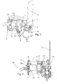
- the brewing module according to Figures 1 and 2 has a Brühmodulgephaseuse 1 and held by the housing or guided a discharge device 3 as the first Brühmodulteil and an injector 5 as a second Brühmodulteil.
- an operating lever 6 By an operating lever 6, the injector 5 between an open position in which the brewing chamber is open and the operating lever is up and a closed position in which the brewing chamber closed and the operating lever is folded down, relative to the housing and the first brewing module part movable.
- Figures 1 and 2 show the brewing module in the open position and with inserted capsule 10.
- For the insertion of the capsule 10 has an insertion opening 11 is present, which also determines the orientation of the capsule during insertion. By indicating the position of the capsule collar 21, the insertion opening also indicates the orientation of the capsule to be selected.
- lateral guide means 31 formed as guide jaws-are present whose function will be described in more detail below.
- the toggle lever is designed so that it forms a self-locking system by the toggle lever in the closed state of the brewing module, when the operating lever 6 is at the stop, is suppressed by a few degrees, ie knee joint, when the operating lever 6 at the bottom stop is, on the other side of that plane 13, which is defined by the respective outer axes of rotation of the arms 8.1, 8.2, as in the open state of the brewing module. Therefore, when the two brewing module parts are pressed apart during the brewing process, the toggle lever is pressed against a stop in the housing and can not open on its own.
- a microswitch 16 may be present, which is actuated by pressing the toggle lever to the stop and, for example, even the same can form the stop.
- the microswitch 16 which controls that certain operations - especially the brewing process itself - can take place only when the brewing chamber is closed.
- FIG. 5 shows - in a different orientation compared to the figures described above - the injector and the discharge device.
- FIGS. 6 and 7 show further views of the diversion device 3.
- the lateral guide jaws 31 protrude from the head 30 of the diversion device 3 in the direction of the injector (ie, inward according to the terminology used herein). In the example shown, they are each divided into an upper and lower lateral guide jaw member with an interruption therebetween. By the lateral guide jaws 31 are defined an outer track 33 and an inner track 36.
- the outer and inner tracks are each defined by groove-like structures, which are designed to guide the collar 21 of the capsule (in the illustrated embodiment, the collar 21 is formed by a circumferential welding edge), wherein the tracks are dimensioned so that the collar of the capsule yet Game has and is not clamped.
- the outer guide track is positioned relative to the insertion opening 11 so that the collar 21 of the capsule inserted when the brewing chamber is open enters the outer track 33.
- a support 35 is formed, on which the collar 21 and / or another part of the capsule 10 comes to rest when it is inserted.
- the inner track 36 is open at the bottom.
- the two grooves can be interchanged with each other - i. E. the first lane is then further out than the second lane.
- the return elements 61 can also intervene laterally from above and below instead of intervening between the guide jaw parts 31.
- the inner, arranged in the interior of the brewing chamber parts of the injector rotated by 90 ° to the Brühhuntachse.
- FIGS. 8 to 12 The operation of the holding jaws and the interaction with return elements 61 of the injector 5 are based on FIGS. 8 to 12 described in more detail.
- FIG. 8 shows a sectional view of the state after the capsule insertion.
- the collar 21 is located in the outer track.
- the outer retention structure supports the collar and prevents the capsule from tilting downwards and inwards, ie to the left in the marked orientation.
- the injector Upon closure of the brewing chamber, the injector is moved toward the diverter and the return member slides into the gap between the upper and lower guide jaw members.
- the capsule is - taken by a capsule seal described in more detail below - taken a bit far and bspw. For example, by extraction-side perforation (extraction mandrels 39) already slightly pierced ( FIG. 9 ).
- a puncture device 38 can be used for the removal, as it is the subject of the European patent application 13 185 359.0 is.
- Other piercing and diversion devices for example according to WO 2010/118544 , are usable.
- an inner retaining structure 37 is formed on the inner side of the inner track 36. This protrudes further radially inward than the outer retention structure 34 and / or is formed at a steeper angle to the axis 20 and / or is more extensive and / or further up / down than the outer containment structure 34, so that retention (force that would have to be expended to forcibly pull the capsule over it) is greater than that of the outer retention structure 34.
- the retention effect of the inner retention structure 36 is also greater than that (acting in the reverse direction) of Mit Spotifypartie 62.
- this mainly comes about that the driving part attacks on the central part of the capsule, the inner retention structure 36, however, above and below it and closer at the corners of the capsule. Since these as a whole bring about a deformation of the capsule more resistance than the middle part of the capsule, the latter deviates inwards and thus allows slippage of the driving part 62 (FIG. FIG. 11 ).
- the outer trajectory 33 is defined by groove-like structures as in the illustrated example.
- an outer retention structure 34 is present on the upper side, which supports the collar 21 from the inside and thus prevents the capsule resting on the support from tipping inwards.
- the inner web may be defined only by retention structures of the type of inner containment structure 36.
- FIG. 13 A detail of the closure head 9 is in FIG. 13 illustrated. This forms a pivotal movement of the lever mitsesde cover 17, which prevents a user can engage in the mechanics of the brewing unit - thereby minimizing the risk of injury.
- the capsule is gripped by a capsule seal of the injector, which also holds it in position.
- This capsule seal can be formed as in WO 2012/045184 described; This publication is expressly referred to.
- FIG. 14 shows the brewing module with a capsule seal 40 which in accordance with the principle WO 2012/045184 is formed as a single-lip seal, which is formed projecting towards the location of the liquid injection, so that the liquid pressure of the liquid admitted from the injection side additionally presses the sealing lip against the capsule.
- the injector 5 has an injection-side piercing device 51 with a plurality of perforation elements 53.
- FIG. 14 A particular optional feature of the injector 5 is shown in FIG. 14 also visible. This is a flow channel 41, which promotes a fluid flow towards the capsule seal 40, even if the capsule is pressed against the injector. By this measure, the capsule seal is already before the water has penetrated into the capsule - ie before the brewing - flowed.
- a sealing of the capsule 10 against the discharge device works here optionally without separate extraction-side seal. Such a sealing is necessary for the from the capsule escaping Brühgetränk enters the pourer and can not drip past the capsule down.
- a matched to the capsule shape sealing surface 32 is present, against which the capsule is pressed flat during the extraction process.
- this sealing surface made of a hard material - for example. Injection molded hard plastic or metal - be made, it being the capsule wall, which is deformable during the brewing process and sealingly pressed against the sealing surface 32.
- a 3/2-way valve 15 is attached by means of a geometry which is injected directly on the injector - ie the valve 15 is present directly on the injector and not as known from the prior art, for example. Via a hose or similar connected thereto.
- the 3/2-way valve has a pump-side connection (inlet), an injection-side connection (outlet) and a drip-water connection (alternative outlet).
- the 3/2-way valve is used as known per se, the discharge of the brewing chamber. In the non-actuated state of the brewing chamber is relieved by a path from the injection-side connection to the drip water connection is open.
- the valve In the actuated state, the path from the inlet to the injection-side connection is free and the drip-water connection is blocked. After completion of the brewing process, the valve returns to the non-actuated state and allows the pressure reduction from the injection-side connection ago by dripping the water into a drip tray. In this case, the pump-side connection is blocked, which also prevents post-evaporation by a sudden pressure drop after the brewing process.
- FIG. 15 shows a sectional view of the diversion device.
- a closure seal 70 which here as the capsule seal 40 is designed as a lip seal. This is in the closed state of the brewing chamber to the housing of the injector 5 and is pressed upon application of pressure against them. This seals the brewing chamber and prevents water leakage even if - for example. For a rinsing - no capsule is inserted.
- a flexible nozzle 81 arranged behind the extraction-side piercing device 38.
- This can, for example, consist of silicone or another food-compatible and elastic material and have a nozzle opening of, for example, between 0.15 mm and 0.4 mm, in particular between 0.2 mm and 0.3 mm.
- Such a nozzle has, inter alia, the effect that the broth is additionally foamed, so that the formation of the popular "crema” is favored.
- FIG. 16 also shows parts of the diversion device 3 in a sectional view in which, in addition to the nozzle 81, the pourer 83 for the brewing beverage is also visible.
- FIG. 18 also shows an optional form of the flexible nozzle 81: on the inlet side, this has an area which narrows towards the nozzle opening and channels the liquid flow.
Abstract
Ein Brühmodul für ein Extraktionsgerät weist ein erstes Brühmodulteil (3) und ein relativ zu diesem bewegbares zweites Brühmodulteil (5) auf. Das erste und das zweite Brühmodulteil bilden eine Ausleitvorrichtung zum Ausleiten eines Extraktionsprodukts aus einer Kapsel mit Extraktionsgut für die Zubereitung von Brühgetränken und einen Injektor zum Einleiten einer Extraktionsflüssigkeit in die Kapsel. Das erste Brühmodulteil weist einen Kopf (30) mit seitlichen Führungsmitteln (31) auf, welche eine erste Bahn (33) und eine zweite Bahn (36) für einen Kapselkragen definieren. Das erste Brühmodulteil (3) bildet ferner eine Auflage (35), welche eine Bewegung der Kapsel nach unten begrenzt, wenn der Kapselkragen sich auf der ersten Bahn befindet. Sie seitlichen Führungsmittel (31) sind steif mit dem Kopf verbunden, und das zweite Brühmodulteil weist ein Rückholmittel (61) auf, welches dazu ausgebildet ist, beim Öffnen der Brühkammer am Kapselkragen (21) anzugreifen und diesen in die zweite Bahn (36) zu bewegen.A brewing module for an extraction device has a first brewing module part (3) and a second brewing module part (5) which can be moved relative to this. The first and second brewing module parts form a discharge device for discharging an extraction product from a capsule with extraction material for the preparation of brewed beverages and an injector for introducing an extraction liquid into the capsule. The first brewing module part has a head (30) with lateral guide means (31) defining a first track (33) and a second track (36) for a capsule collar. The first brewing module part (3) further forms a support (35) which limits downward movement of the capsule when the capsule collar is on the first path. The lateral guide means (31) are rigidly connected to the head, and the second brewing module part has return means (61) adapted to engage the capsule collar (21) upon opening the brewing chamber and feed it into the second path (36) move.
Description
Die Erfindung betrifft Extraktionsgeräte zum Zubereiten von Getränken oder dergleichen aus einem in einer Kapsel enthaltenen Extraktionsgut, beispielsweise gemahlenem Kaffee. Sie betrifft insbesondere ein Brühmodul für ein Extraktionsgerät sowie ein Extraktionsgerät mit einem solchen Brühmodul.The invention relates to extraction devices for preparing beverages or the like from an extraction material contained in a capsule, for example ground coffee. It relates in particular to a brewing module for an extraction device and to an extraction device having such a brewing module.
Extraktionsgeräte zum Zubereiten von Getränken oder dergleichen aus einem in einer Portionsverpackung vorhandenen Extraktionsgut sind unter anderem als Kaffee- oder Espressomaschinen bekannt. In vielen entsprechenden Systemen sind die Portionsverpackungen als Kapseln ausgebildet, in denen das Extraktionsgut bspw. luftdicht abgeschlossen ist. Für die Extraktion wird die Kapsel angestochen, beispielsweise an zwei einander gegenüberliegenden Seiten. Auf der ersten Seite wird dann eine Extraktionsflüssigkeit - im Allgemeinen heisses Wasser - eingeleitet. Auf der zweiten Seite wird das Extraktionsprodukt aus der Kapsel ausgeleitet. Dies geschieht in einem sogenannten Brühmodul. Ein solches weist eine Brühkammer auf, in der die Kapsel aufgenommen wird. Besonders beliebt sind Brühmodule, bei welchen die Kapsel eingeworfen und die Brühkammer bspw. mittels eines Bedienhebels verschlossen wird, wobei beim erneuten Öffnen der Brühkammer nach dem Brühvorgang die Kapsel selbsttätig aus der Brühkammer entfernt und in einen Kapselbehälter ausgeworfen wird. Solche Brühmodule mit selbsttätigem Kapselauswurf sind im Allgemeinen als horizontale Brühmodule ausgebildet, d.h. der Kapseleinwurf erfolgt von oben, das Verschliessen der Brühkammer ist eine horizontale Relativbewegung zweier Brühkammerteile, die Brühflüssigkeit fliesst im Wesentlichen horizontal, und der Kapselbehälter ist unterhalb der Brühkammer ausgebildet.Extraction devices for preparing beverages or the like from an extraction material present in a portion packaging are known, inter alia, as coffee or espresso machines. In many corresponding systems, the portion packages are designed as capsules, in which the extraction material, for example, is airtight. For extraction, the capsule is pierced, for example on two opposite sides. On the first side then an extraction liquid - generally hot water - is introduced. On the second side, the extraction product is discharged from the capsule. This happens in a so-called brewing module. Such has a brewing chamber in which the capsule is received. Particularly popular are brewing modules in which the capsule is inserted and the brewing chamber, for example, is closed by means of an operating lever, the capsule being automatically removed from the brewing chamber and ejected into a capsule container when the brewing chamber is opened again after the brewing process. Such brewing modules with automatic capsule ejection are generally designed as horizontal brewing modules, ie the capsule is inserted from above, the closure of the brewing chamber is a horizontal relative movement of two brewing chamber parts, the brewing liquid flows in the Essentially horizontal, and the capsule container is formed below the brewing chamber.
Bei Brühmodulen dieser Art ist sicherzustellen, dass die eingeworfene Kapsel gehalten wird, bis die Brühkammer verschlossen ist, dass sie aber nach unten fällt, wenn die Brühkammer nach dem Brühprozess wieder geöffnet wird. Die
Diese Lösung bedingt, dass ein relativ ausgeprägter seitlicher Kragen vorhanden ist. Ausserdem ist sie relativ aufwändig zu realisieren.This solution requires that a relatively pronounced lateral collar is present. Moreover, it is relatively complex to realize.
Die
Auch diese Lösung bedingt einen relativ ausgeprägten seitlichen Kragen, der ausserdem - in eine axiale Richtung - verformbar sein muss. Sie ist daher nicht für alle Kapselsorten geeignet.Also, this solution requires a relatively pronounced lateral collar, which also - in an axial direction - must be deformable. It is therefore not suitable for all capsule types.
Ausgehend vom Stand der Technik stellt sich der Erfindung die Aufgabe, ein Brühmodul für ein Extraktionsgerät, beispielsweise eine Kaffeemaschine, zum portionenweisen Zubereiten eines Getränkes oder anderen Extraktionsprodukts aus einem in einer Kapsel verpackten Extraktionsgut, zur Verfügung zu stellen, das Nachteile bestehender Brühmodule überwindet und das eine einfache und kompakte Bauweise sowie eine grosse Flexibilität beim Kapseldesign ermöglicht. Das Brühmodul sollte insbesondere für einen horizontalen Einbau und vorzugsweise auch für grosse Brühdrücke von über 10 bar, bspw. bis 20 bar, geeignet sein, wobei auch deutlich niedrigere Brühdrücke von bpsw. ca. 1 bar nicht ausgeschlossen sind.Starting from the prior art, the invention has the object to provide a brewing module for an extraction device, such as a coffee machine, for portionwise preparation of a beverage or other extraction product from a packed in a capsule extraction material, overcomes the disadvantages of existing brewing modules and the a simple and compact design and a great flexibility in the capsule design allows. The brewing module should in particular be suitable for horizontal installation and preferably also for large brewing pressures of more than 10 bar, for example up to 20 bar, and also significantly lower brewing pressures of bpsw. 1 bar are not excluded.
Gemäss einem ersten Aspekt weist das Brühmodul ein erstes Brühmodulteil und ein relativ zu diesem bewegbares zweites Brühmodulteil auf, wobei das erste und das zweite Brühmodulteil eine Ausleitvorrichtung zum Ausleiten eines Extraktionsprodukts aus der Kapsel und einen Injektor zum Einleiten einer Extraktionsflüssigkeit in die Kapsel bilden - beispielsweise ist das erste Brühmodulteil die Ausleitvorrichtung und das zweite Brühmodulteil der Injektor - oder umgekehrt. In einer geschlossenen Stellung (das erste und zweite Brühmodulteil sind bspw. "zusammen") wird eine Brühkammer geschlossen, welche die Kapsel beim Brühvorgang mindestens teilweise umgibt.According to a first aspect, the brewing module has a first brewing module part and a second brewing module part movable relative thereto, the first and the second brewing module part forming a discharge device for discharging an extraction product from the capsule and an injector for introducing an extraction liquid into the capsule, for example the first brewing module part the discharge device and the second brewing module part of the injector - or vice versa. In a closed position (the first and second brewing module part If, for example, "together"), a brewing chamber is closed, which at least partially surrounds the capsule during the brewing process.
Zum Öffnen und Verschliessen der Brühkammer kann das zweite Brühmodulteil relativ zum ersten Brühmodulteil linear entlang einer axialen Richtung - d.h. translatorisch bzw. im Wesentlichen translatorisch - bewegbar sein. Eine Schwenkbewegung der Brühmodulteile relativ zueinander ist nicht ausgeschlossen, aber im Allgemeinen unnötig. Insbesondere wird in Ausführungsformen die Kapsel beim Verschliessen der Brühkammer nicht aktiv verschwenkt. Es kann auch vorgesehen sein, dass die Kapsel beim Verschliessen auch nicht verkippt, d.h. die Orientierung der Kapsel bleibt beim Verschliessen der Brühkammer im Wesentlichen erhalten.In order to open and close the brewing chamber, the second brewing module part can move linearly along an axial direction relative to the first brewing module part - i.e. translational or substantially translational - be movable. A pivoting movement of the brewing module parts relative to each other is not excluded, but generally unnecessary. In particular, in embodiments, the capsule is not actively pivoted when closing the brewing chamber. It may also be provided that the capsule also does not tilt during closure, i. the orientation of the capsule is substantially preserved when closing the brewing chamber.
Das erste Brühmodulteil weist einen Kopf mit seitlichen (Kapsel-)Führungsmitteln auf. Diese sind am Kopf befestigt und mit diesem verbunden. Die seitlichen Führungsmittel definieren eine im Wesentlichen vertikale erste Bahn für einen Kapselkragen, welcher bspw. durch eine Schweissnaht oder dergleichen gebildet sein kann. Die Führungsmittel weisen je ein in einem oberen Bereich der ersten Bahn eine äussere Rückhaltestruktur auf, die einem Bewegen des Kragens aus der ersten Bahn nach innen entgegenstehen. Ausserdem bildet das erste Brühmodulteil eine Auflage aus, welche in Einwurfrichtung unterhalb der Bahn ausgebildet ist und ein Fallen der Kapsel nach unten verhindert, wenn der Kapselkragen entlang der ersten Bahn geführt ist. Die erste Bahn kann bspw. durch eine erste Führungsnut gebildet sein. Die Auflage kann durch eine Begrenzung der ersten Führungsnut - oder allgemein der ersten Bahn - gegen unten gebildet sein.The first brewing module part has a head with lateral (capsule) guiding means. These are attached to the head and connected to it. The lateral guide means define a substantially vertical first path for a capsule collar, which may be formed, for example, by a weld or the like. The guide means each have an outer retention structure in an upper portion of the first track which opposes inward movement of the collar from the first track. In addition, the first brewing module part forms a support, which is formed in the direction of insertion below the web and prevents falling of the capsule down when the capsule collar is guided along the first path. The first path can be formed, for example, by a first guide groove. The support may be formed by a boundary of the first guide - or generally the first track - against bottom.
In diesem Text beziehen sich generell die Begriffe "innen" und "aussen" auf axiale Richtungen hin zur Mitte der Brühkammer bzw. davon weg. Axiale Richtungen sind Richtungen entlang der im Wesentlichen horizontalen Achse Injektor-Ausleitvorrichtung, welche auch einer Kapselachse entsprechen kann. Auf bezüglich dieser Achse radial-horizontale Richtungen wird durch die Begriffe "radial-innen" und "radial-aussen" Bezug genommen. "Oben" und "Unten" bezeichnen die entsprechenden vertikalen Richtungen bei einer bestimmungsgemässen Verwendung des Brühmoduls, bei welcher die Kaffeemaschine mit dem Brühmodul auf einer horizontalen Oberfläche abgestellt ist.In this text, the terms "inside" and "outside" generally refer to axial directions toward and away from the center of the brewing chamber. Axial directions are Directions along the substantially horizontal axis injector-diverter, which may also correspond to a capsule axis. With respect to this axis, radial-horizontal directions are referred to by the terms "radially inward" and "radially outward". "Up" and "Down" designate the corresponding vertical directions in a proper use of the brewing module, in which the coffee machine with the brewing module is placed on a horizontal surface.
Der Kapselkragen kann beispielsweise ein konventioneller, ausgeprägter und auf der Ebene einer der Endflächen abstehender umlaufender Kragen sein. Er kann jedoch auch gemäss einer alternativen Kapselform weniger ausgeprägt sein und bspw. als umlaufender Schweissrand/Schweissbraue ausgebildet sein, bspw. wie er von Kapseln gemäss
Das zweite Brühmodulteil weist Rückholmittel auf, welche beim Öffnen der Brühkammer (d.h. beim Auseinanderbewegen des ersten und zweiten Brühmodulteils) am Kragen angreifen um diesen durch die Öffnungsbewegung in die zweite Bahn zu bewegen.The second brewing module part has return means which, upon opening the brewing chamber (i.e., moving the first and second brewing module parts apart), engage the collar to move it through the opening movement into the second path.
Die seitlichen Führungsmittel können beispielsweise fest und steif, d.h. im Wesentlichen relativ zum Kopf unbeweglich mit diesem verbunden sein. Das kann herstellungs- und wartungstechnisch besonders günstig sein. Dabei bleiben die seitlichen Führungsmittel beispielsweise während des ganzen Prozesses seitlich in Bezug auf den Kopf unbeweglich. Auch während des Brühprozesses verbleiben die seitlichen Führungsmittel zum Beispiel im Kontakt mit der Kapsel. Beim Verschieben aus der ersten Bahn und gegebenenfalls über die erste Bahn hinweg in die zweite Bahn wird dann die Kapsel leicht deformiert, bspw. durch radiale Deformation. Insbesondere kann der bspw. in sich formsteife Kragen quasi leicht nach radial-innen weggedrückt werden.The lateral guide means may, for example, be rigid and rigid, ie substantially immovable relative to the head. This can be particularly favorable in terms of production and maintenance. The lateral guide means, for example, during the entire process remain immovable laterally with respect to the head. Even during the brewing process, the lateral guide means remain in contact with the capsule, for example. When moving out of the first path and optionally across the first pathway into the second path, the capsule is then slightly deformed, for example, by radial Deformation. In particular, the collar, which is dimensionally stable, for example, can virtually be pushed away radially inward.
Es ist aber auch möglich, dass die seitlichen Führungsmittel entgegen einer Federkraft (ein wenig) nach aussen auslenkbar sind. Dann kann beim Verschieben der Kapsel relativ zu den seitlichen Führungsmitteln anstelle einer Kapsel oder ergänzend dazu eine Auslenkung der seitlichen Führungsmittel treten.But it is also possible that the lateral guide means against a spring force (a little) are deflected outwards. Then, when moving the capsule relative to the lateral guide means instead of a capsule or in addition thereto, a deflection of the lateral guide means occur.
Ergänzend oder alternativ können auch die Rückholmittel während des Brühprozesses mit der Kapsel in Eingriff bleiben. So kann sich der Kapselkragen beispielsweise während des Brühprozesses in einer von den Rückholmitteln gebildeten Aufnahme befinden, in welcher er während des Anschliessenden Öffnens der Brühkammer auch mitbewegt wird, bis er in die zweite Bahn gelangt ist.Additionally or alternatively, the return means may remain engaged with the capsule during the brewing process. For example, during the brewing process, the capsule collar can be located in a receptacle formed by the return means, in which it is also moved during the subsequent opening of the brewing chamber until it has entered the second path.
Wie die seitlichen Führungsmittel können auch die Rückholmittel seitlich nicht bewegbar sondern fest an einem Gehäuse des zweiten Brühmodulteils vorhanden sein. Es ist jedoch - unabhängig von einer möglichen Auslenkbarkeit der seitlichen Führungsmittel - möglich, dass die Rückholmittel radial entgegen einer Federkraft auslenkbar sind.Like the lateral guide means, the return means can not laterally be movable but can also be fixed to a housing of the second brewing module part. However, it is possible-regardless of a possible deflectability of the lateral guide means-that the return means are deflectable radially against a spring force.
Die Führungsmittel können bspw. beidseitig der Kapsel gabelartig angeordnet sein und je eine Aufnahme für den Kapselkragen aufweisen. Die seitlichen Führungsmittel weisen dann bspw. je zwei Führungsmittelteile auf, zwischen welche die Rückholmittel bei verschlossener Brühkammer eingreifen, und/oder die Rückholmittel greifen von oben und unten an der Kapsel an.The guide means may, for example, be arranged like a fork on both sides of the capsule and each have a receptacle for the capsule collar. The lateral guide means then have, for example, two guide means each, between which the return means engage in a closed brewing chamber, and / or the return means engage from above and below on the capsule.
In einer Ausführung mit die Kapsel vollständig umschliessender Brühkammer ist durch die umschliessenden Elemente des ersten und zweiten Brühmodulteils - bspw. ggf. inklusive Dichtung - ein Brühkammerinneres definiert. Die seitlichen Führungsmittel und/oder die Rückholmittel befinden sich dann bei geschlossener Brühkammer im Brühkammerinneren - ebenso wie eine gegebenenfalls vorhandene Kapseldichtung.In an embodiment with the capsule completely enclosing brewing chamber is defined by the enclosing elements of the first and second brewing module part - for example, if necessary, including seal - a Brühkammerinneres. The lateral guide means and / or the return means are then in the closed brewing chamber in the brewing chamber interior - as well as an optionally existing capsule seal.
Dieser Ansatz unterscheidet sich vom Stand der Technik, gemäss welchem die Mittel, welche die Kapsel nach dem Einwurf in einer Zwischenposition gehalten wird, beim Schliessen der Brühkammer entfernt werden müssen, bspw. durch eine Schwenkbewegung nach aussen oder nach unten. Der erfindungsgemässe Ansatz ermöglicht also eine Konstruktion mit einem Minimum an beweglichen Teilen, was sowohl in Bezug auf Verlässlichkeit als auch in Bezug auf Herstellungskosten günstig ist.This approach differs from the prior art, according to which the means which the capsule is held after insertion in an intermediate position, must be removed when closing the brewing chamber, for example. By a pivoting movement to the outside or down. The inventive approach thus allows a design with a minimum of moving parts, which is favorable both in terms of reliability and in terms of manufacturing costs.
Beim Schliessen der Brühkammer kann der Kapselkragen aus der ersten Bahn durch das zweite Brühmodulteil nach aussen, d.h. zum Kopf des ersten Brühmodulteils hin bewegt werden. In dieser Brühposition ist die Kapsel - schon vor dem Brühprozess oder durch den während des Brühprozesses in der Kapsel aufgebauten Innendruck bewirkt - von Perforationselementen des ersten Brühmodulteils angestochen. Aus dieser Brühposition wird dann beim Öffnen die Kapsel durch die Rückholmittel herausgezogen bis der Kragen zur zweiten Bahn gelangt ist. Von dort aus kann die Kapsel dann nach unten in einen Kapselbehälter fallen.Upon closure of the brewing chamber, the capsule collar may exit the first path through the second brewing module portion, i. to the head of the first Brühmodulteils be moved. In this brewing position, the capsule is pierced by perforation elements of the first brewing module part, even before the brewing process or as a result of the internal pressure built up in the capsule during the brewing process. From this brewing position, the capsule is then pulled out by the return means when opening the collar until it reaches the second path. From there, the capsule can then fall down into a capsule container.
Es kann insbesondere vorgesehen sein, dass die zweite Bahn in Bezug auf die Brühkammer weiter innen - d.h. näher bei der Seite des zweiten Brühmodulteilsangeordnet ist als die erste Bahn. Dann wird der Kapselkragen unter Umständen während des Öffnens der Brühkammer aus der Brühposition über die erste Bahn hinweg in die zweite Bahn gezogen.It may be provided, in particular, that the second path is positioned further inwardly relative to the brewing chamber - that is, closer to the side of the second brewing module part than the first path. Then the capsule collar may be pulled during the opening of the brewing chamber from the brewing position across the first web away in the second path.
Innenseitig der zweiten Bahn ist bspw. eine zweite Rückhaltestruktur vorhanden, welche den Kapselkragen während der Öffnungsbewegung zurückhält, sobald dieser in der zweiten Bahn angekommen ist. Die Rückhaltekraft dieser ist dann grösser als die entsprechende Kraft der Rückholmittel, so dass der Kragen beim weiteren Öffnen aus der Aufnahme der Rückholmittel hinaus gelangt. Dies kann bspw. dadurch bewirkt sein, dass diese Rückhaltestruktur weiter nach radial-innen ragt, einen steileren Winkel zur Achse bildet und/oder ausgedehnter ist. Zusätzlich oder alternativ dazu kann auch vorgesehen sein, dass die Rückholmittel in der Mitte (bezüglich der Vertikalen) des Kapselkragens angreifen, wohingegen die zweite Rückhaltestruktur oberhalb und unterhalb angreift. Bei einer im Wesentlichen würfel- oder quaderförmigen Kapsel bedeutet das, dass die Rückhaltestruktur näher bei den Ecken und Kanten der Kapsel angreift, wo diese einer Verformung mehr Widerstand entgegenbringt, als die Rückholmittel.On the inside of the second path, for example, a second retention structure is provided which retains the capsule collar during the opening movement as soon as it has arrived in the second path. The retention force of this is then greater than the corresponding force of the return means, so that the collar passes from the receptacle of the return means on further opening. This can be effected, for example, by the fact that this retaining structure projects further radially inwards, forms a steeper angle to the axis and / or is more extensive. Additionally or alternatively, it may also be provided that the return means engage in the middle (with respect to the vertical) of the capsule collar, whereas the second retaining structure engages above and below. For a substantially cube or cuboid capsule, this means that the retention structure engages closer to the corners and edges of the capsule, where it presents more resistance to deformation than the return means.
Die Ausleitvorrichtung und der Injektor sind vorzugsweise einander gegenüberliegend angeordnet und weisen beispielsweise eine extraktionsseitige Anstechvorrichtung mit mindestens einem in die Brühkammer hinein abstehenden Perforationselement bzw. eine injektionsseitige Anstechvorrichtung, ebenfalls mit mindestens einem in die Brühkammer hinein abstehenden Perforationselement auf. Die Perforationselemente sind bspw. zum Anstechen von tiefgezogenen Kunststoff-Kapselwandungen, bspw. aus Polypropylen mit bspw. einer Dicke von zwischen 0.2 mm und 0.5 mm oder 0.4 mm, bspw. zwischen 0.25 mm und 0.35 mm ausgebildet; als solche unterscheiden sie sich unter Umständen von Mitteln zum Perforieren von Aluminiumkapseln. Auch Anstechvorrichtungen für andere Kapselwandungsmaterialien als tiefgezogene Kunststoffe können jedoch vorhanden sein.The diversion device and the injector are preferably arranged opposite one another and have, for example, an extraction-side piercing device with at least one perforation element projecting into the brewing chamber or an injection-side piercing device, likewise with at least one perforation element projecting into the brewing chamber. The perforation elements are formed, for example, for piercing deep-drawn plastic capsule walls, for example of polypropylene with, for example, a thickness of between 0.2 mm and 0.5 mm or 0.4 mm, for example between 0.25 mm and 0.35 mm; as such, they may differ from means for perforating aluminum capsules. However, piercing devices for other capsule wall materials than thermoformed plastics may also be present.
Der Injektor des Brühmoduls weist in Ausführungsformen eine Kapseldichtung auf, welche die Kapsel entlang einer umlaufenden Mantelfläche umgreift. Die Kapseldichtung kann insbesondere eine - einzige - Dichtungslippe aufweisen, welche zum Ort der Flüssigkeitsinjektion hin ragend ausgebildet ist. Als Option kann im Injektor ein Anströmkanal vorhanden sein welcher injiziertes Brühwasser schon vor Beginn des Brühprozesses zur Kapseldichtung hin lenkt und die Dichtung - insbesondere die Dichtungslippe - gegen die Mantelfläche drücken lässt.In embodiments, the injector of the brewing module has a capsule seal, which surrounds the capsule along a circumferential lateral surface. In particular, the capsule seal may have a single sealing lip, which protrudes toward the location of the liquid injection. As an option, an inflow channel may be present in the injector which directs injected brewing water to the capsule seal even before the start of the brewing process and allows the seal - in particular the sealing lip - to be pressed against the lateral surface.
Eine Kapseldichtung kann auch - wie bspw. in
Auch extraktionsseitig (auf Seite der Ausleitvorrichtung) kann optional eine Dichtung vorhanden sein. Gemäss einer Alternative wird die Abdichtung der Kapsel jedoch nicht durch eine solche zusätzliche Dichtung, sondern durch die Dichtwirkung der gegen eine nichtelastische Dichtfläche gedrückten Kapselwand bewirkt. Die Dichtfläche kann dabei eine gekrümmte oder auch ebene Fläche sein, und die Dichtwirkung durch eine Verformbarkeit der während des Brühverfahrens heissen Kapselwand unterstützt sein.Also on the extraction side (on the side of the diversion device) may optionally be present a seal. According to one alternative, however, the sealing of the capsule is not caused by such an additional seal, but by the sealing effect of the pressed against a non-elastic sealing surface capsule wall. The sealing surface may be a curved or flat surface, and the sealing effect be supported by a deformability of the hot during the brewing capsule wall.
Ein weiteres optionales Merkmal betrifft die Mechanik zum Bewegen des zweiten Brühmodulteils relativ zum ersten Brühmodulteil (die Relativbewegung kann ein Bewegen des zweiten Brühmodulteils und/oder des ersten Brühmodulteils relativ zu einem ortsfesten Gehäuse beinhalten). Gemäss einer Ausführungsform wird eine auslösende Bewegung - bspw. eines Bedienhebels oder auch eines elektrischen Antriebs, jeweils mit oder ohne Getriebeüber- oder -untersetzung - auf einen Kniehebel übertragen, wobei ein Kniegelenk des Kniehebels beim Schliessen überdrückt wird, d.h. sich im geschlossenen Zustand des Brühmoduls auf einer anderen Seite derjenigen Ebene befindet, welche durch die jeweils äusseren Drehachsen der Arme des Kniehebels definiert wird, als im offenen Zustand des Brühmoduls.Another optional feature relates to the mechanism for moving the second brewing module part relative to the first brewing module part (the relative movement may involve moving the second brewing module part and / or the first brewing module part relative to a stationary housing). According to one embodiment, a triggering movement - for example. An operating lever or an electric Drive, in each case with or without Getriebeüber- or -untersetzung - transferred to a knee lever, wherein a knee joint of the toggle lever is suppressed when closing, ie in the closed state of the brewing module on another side of that level, which by the respective outer axes of rotation of the arms the knee lever is defined, as in the open state of the brewing module.
Ein solches Überdrücken - im geschlossenen Zustand des Brühmoduls gegen einen Anschlag - hat eine selbsthemmende Wirkung: durch den während des Brühprozesses entstehenden Innendruck werden die Brühmodulteile auseinandergepresst, wodurch der Kniehebel noch mehr gegen den Anschlag gedrückt wird - die Brühkammer kann sich nicht selbsttätig öffnen.Such over-pressing - in the closed state of the brewing module against a stop - has a self-locking effect: by the internal pressure generated during the brewing process the brewing module parts are pressed apart, whereby the toggle is pressed even more against the stop - the brewing chamber can not open automatically.
Diese optionalen Merkmale (Lippendichtung mit Anströmkanal; extraktionsseitiges Abdichten durch nicht-elastische Dichtfläche; überdrückter Kniehebel) wirken - je für sich oder in Kombinationen - besonders günstig mit dem vorstehend beschriebenen Konzept zusammen. Sie sind jedoch an sich auch - ebenfalls je für sich oder in Kombinationen - in anderen Brühmodulen für ein Extraktionsgerät einsetzbar, welche ein erstes Brühmodulteil und ein relativ zu diesem bewegbares zweites Brühmodulteil aufweisen, wobei das erste und das zweite Brühmodulteil eine Ausleitvorrichtung zum Ausleiten eines Extraktionsprodukts aus einer Kapsel mit Extraktionsgut für die Zubereitung von Brühgetränken und einen Injektor zum Einleiten einer Extraktionsflüssigkeit in die Kapsel bilden.These optional features (lip seal with inflow channel, extraction-side sealing by non-elastic sealing surface, over-pressed toggle lever) - each in its own right or in combination - interact particularly favorably with the concept described above. However, they are also per se - also individually or in combinations - used in other brewing modules for an extraction device having a first brewing module part and a movable relative to this second brewing module part, wherein the first and the second brewing module part a discharge device for discharging an extraction product from a capsule with extraction material for the preparation of brewed beverages and an injector for introducing an extraction liquid into the capsule.
Gemäss einer speziellen Ausführungsform ist bspw. die Brühkammer für die Aufnahme einer im sich Gegensatz zum Stand der Technik nicht zur Ausleit- oder Injektorseite konisch verbreiternden Kapsel sondern einer bspw. würfelförmigen oder quaderförmigen Kapsel ausgebildet. Unter quader- bzw. würfelförmig versteht man hier eine Form, die von der geometrisch exakten Quader- bzw. Würfelform nicht so weit abweichen, dass sie funktionell sehr verschieden wären; bspw. ist die Form eines Pyramidenstumpfs mit rechteckiger bzw. quadratischer Grundfläche, wobei die an die Grundfläche angrenzenden Seitenflächen gegenüber der Senkrechten zur Grundfläche um nur einen kleinen Neigungswinkel α von bspw. höchstens 2° mit eingeschlossen. Die Quader- bzw. Würfelform kann einen umlaufenden Kragen - bspw. in Form eines Schweissrandes/einer Schweissbraue - aufweisen, der bspw. maximal 1.5 mm seitlich hervorsteht und bspw. von einer Endflächen-Ebene abgesetzt ist.For example, according to a specific embodiment, the brewing chamber is designed to accommodate a capsule that conically widening in contrast to the prior art not to the diversion or injector side, but instead to a cuboid or cube-shaped capsule, for example. Under cuboid or cube-shaped understands here a shape that does not deviate so much from the geometrically exact cuboid or cube shape that they would be functionally very different; For example, the shape of a truncated pyramid with a rectangular or square base, wherein the adjacent to the base side surfaces with respect to the perpendicular to the base by only a small inclination angle α of, for example, at most 2 ° included. The cuboid or cube shape can have a peripheral collar-for example, in the form of a welding edge / a sweat brow-which, for example, protrudes laterally at most 1.5 mm and, for example, is offset from an end surface plane.
Das Brühmodul ist wie bereits erwähnt als horizontales Brühmodul ausgebildet. Das schliesst jedoch nicht aus, dass das Brühmodul als Ganzes leicht verkippt angeordnet sein kann, bspw. kann sie zum ersten Brühmodulteil hin nach unten abschüssig sein. Die Neigung der Achse Injektor-Ausleitvorrichtung zur Horizontalen hin beträgt dann vorzugsweise höchstens 15°, insbesondere zwischen 0° und 10°.The brewing module is, as already mentioned, designed as a horizontal brewing module. However, this does not exclude that the brewing module as a whole can be arranged slightly tilted, for example. It may be downhill to the first brewing module part down. The inclination of the axis injector-deflector towards the horizontal is then preferably at most 15 °, in particular between 0 ° and 10 °.
In Ausführungsformen umschliesst die Brühkammer die Kapsel vollständig, d.h. das erste Brühmodulteil und das zweite Brühmodulteil weisen Elemente auf, die passgenau einander entsprechen und in der geschlossenen Stellung zusammen die Brühkammer bilden. Die vom ersten Brühmodulteil gebildeten Wandungsteile und die vom zweiten Brühmodulteil gebildeten Wandungsteile können in der geschlossenen Position gegeneinander abgedichtet sein, bspw. durch eine umlaufende Verschlussdichtung. Diese Verschlussdichtung kann bspw. eine Lippendichtung aufweisen, welche an einem der Brühmodulteile befestigt ist und beim Verschliessen der Brühkammer gegen eine Fläche des anderen Brühmodulteils anstösst. Eine dergestalt abgeschlossene Brühkammer ermöglicht ein Spülen des Extraktionsgeräts bzw. des Brühmoduls, ohne dass eine Kapsel eingelegt werden müsste - was für den Benutzer ein markanter Vorteil ist. Dies schliesst jedoch die Verwendung einer Spül- oder Platzhalterkapsel während des Spül- oder Reinigungsvorgangs - mit abgeschlossener oder nicht vollständig abgeschlossener Brühkammer - nicht aus.In embodiments, the brewing chamber encloses the capsule completely, ie, the first brewing module part and the second brewing module part have elements that exactly match one another and in the closed position together form the brewing chamber. The wall parts formed by the first brewing module part and the wall parts formed by the second brewing module part can be sealed off from one another in the closed position, for example by a circumferential sealing seal. This sealing gasket may, for example, have a lip seal which is fastened to one of the brewing module parts and abuts against a surface of the other brewing module part when the brewing chamber is closed. A brewing chamber finished in this way allows rinsing of the extraction device or of the brewing module without having to insert a capsule - which is a significant advantage for the user. However, this excludes the use of a rinse or placeholder capsule during the rinse or Cleaning process - with a complete or incomplete brewing chamber - not off.
Durch eine solche Verschlussdichtung kann die Brühkammer zweistufig abgedichtet sein. Eine erste Dichtungsstufe wird durch mindestens eine Kapseldichtung gebildet, welche die Kapsel umgreift und verhindern, dass die eingeleitete Extraktionsflüssigkeit bzw. das ausgeleitete Extraktionsprodukt an der Kapsel vorbei fliessen. Diese erste Dichtungsstufe dichtet die Kapsel gegen den Injektor bzw. gegen die Ausleitvorrichtung ab. Als zweite Dichtungsstufe dichtet die Verschlussdichtung die Brühmodulteile gegeneinander ab. Sie kann einerseits der ergänzenden Abdichtung während des Brühvorgangs dienen. Andererseits kann sie wie erwähnt dem Abdichten während eines Spülvorgangs dienen.By such a closure seal the brewing chamber can be sealed in two stages. A first sealing step is formed by at least one capsule seal, which surrounds the capsule and prevent the introduced extraction liquid or the extracted extraction product from flowing past the capsule. This first sealing step seals the capsule against the injector or against the diversion device. As the second sealing step, the closure seal seals the brewing module parts against each other. On the one hand, it can serve as a supplementary seal during the brewing process. On the other hand, as mentioned, it can serve for sealing during a rinsing process.
Zusätzlich Gegenstand der Erfindung ist ein Verfahren zum Brühen eines Brühgetränks unter Verwendung einer Kapsel. Dieses wird bspw. mit einem Brühmodul bzw. einem Extraktionsgerät der vorstehend beschriebenen Art durchgeführt und kann die die Schritte umfassen:
- Einwerfen einer Portionenkapsel mit einem Extraktionsgut, bspw. durch eine positionierende Einwurföffnung, so, dass ein Kragen der Kapsel auf der ersten Bahn positioniert wird und dass die Kapsel auf der Auflage aufliegt;
- Verschliessen der Brühkammer durch Bewegen des zweiten Brühmodulteils relativ zum ersten Brühmodulteil, derart, dass die Kapsel mindestens durch ein Perforationselement eines durch das erste und/oder das zweite Brühmodulteil gebildeten Injektors angestochen wird, wodurch Einleitöffnungen in der Kapsel entstehen;
- Einleiten einer Extraktionsflüssigkeit in die Kapsel durch die Einleitöffnungen (bspw. von heissem Wasser unter Gebrauch einer Pumpe und optional eines Ventils);
- Ausleiten der Extraktionsflüssigkeit aus der Kapsel durch Ausleitöffnungen, die von Perforationselementen einer durch das erste und/oder das zweite Brühmodulteil gebildeten Ausleitvorrichtung erzeugt wurden;
- Anschliessend an das Ausleiten, Öffnen der Brühkammer durch Bewegen des zweiten Brühmodulteils relativ zum ersten Brühmodulteil, wodurch die Kapsel durch die Rückholelemente vom ersten Brühmodulteil weg gezogen wird, bis der Kragen entlang der zweiten Bahn positioniert ist und Fortsetzen des Öffnungsprozesses bis die Kapsel aus der geöffneten Brühkammer nach unten fällt.
- Inserting a portion capsule with an extraction material, for example by a positioning insertion opening, such that a collar of the capsule is positioned on the first path and that the capsule rests on the support;
- Closing the brewing chamber by moving the second brewing module part relative to the first brewing module part, such that the capsule is pierced at least by a perforation element of an injector formed by the first and / or the second brewing module part, whereby introduction openings are formed in the capsule;
- Introducing an extraction fluid into the capsule through the inlet ports (eg, from hot water using a pump and optionally a valve);
- Discharging the extraction liquid from the capsule through discharge openings formed by perforation elements of a discharge device formed by the first and / or the second brewing module part;
- Following discharge, opening the brewing chamber by moving the second brewing module portion relative to the first brewing module portion whereby the capsule is pulled by the retrieval members away from the first brewing module portion until the collar is positioned along the second path and continuing the opening process until the capsule is removed Brewing chamber falls down.
Weiter Gegenstand der Erfindung ist ein Extraktionsgerät, insbesondere eine Getränkezubereitungsmaschine, bspw. Kaffeemaschine oder Teemaschine, mit einem Wassertank oder Wasseranschluss, einem Wassererhitzer, einer Wasserpumpe und einem Brühmodul der beschriebenen Art, wobei Wassertank, Wassererhitzer und Wasserpumpe so an das Brühmodul angeschlossen sind, dass von der Pumpe gefördertes erhitztes Wasser durch den Injektor in die Kapsel einleitbar ist.The invention further relates to an extraction device, in particular a beverage preparation machine, for example. Coffee or tea, with a water tank or water connection, a water heater, a water pump and a brewing module of the type described, with water tank, water heater and water pump are connected to the brewing module, that heated water delivered by the pump can be introduced into the capsule through the injector.
Ausführungsbeispiele der Erfindung werden nachfolgend anhand von Zeichnungen beschrieben. In den Zeichnungen bezeichnen gleiche Bezugszeichen gleiche oder analoge Elemente. Die Zeichnungen zeigen teilweise einander entsprechende Elemente von Figur zu Figur in unterschiedlichen Massstäben. Es zeigen:
-
Figur 1 -
Figur 2 eine Schnittdarstellung des Brühmoduls; -
Figur 3 -
Figur 4 einDetail zu Figur 3 , welches auch einen Mikroschalter zeigt; -
Figur 5 -
Figuren 6 und 7 -
Figur 8 -
Figur 9 -
Figuren 11 und 12 je eine zuFigur 9 analoge Darstellung der Anordnung während verschiedener Stadien des Öffnens der Brühkammer dargestellt; -
Figur 13 -
Figur 14 in einer Schnittdarstellung ein Detail des Injektors; und -
Figuren 15 und 16
-
FIG. 1 a view of a brewing module according to the invention; -
FIG. 2 a sectional view of the brewing module; -
FIG. 3 a view of parts of the closing mechanism of the brewing module; -
FIG. 4 a detail tooFIG. 3 which also shows a microswitch; -
FIG. 5 a view of the injector and relative to this as in the open position of the brewing chamber positioned diverter; -
FIGS. 6 and 7 ever another view of the diversion device; -
FIG. 8 a sectional view of the capsule and parts of the diversion after the insertion of the capsule and before the closure of the brewing chamber - shown cut along a horizontal plane below the capsule center; -
FIG. 9 a sectional view of parts of the capsule, the diverter and the injector during the closing of the brewing chamber - shown cut along a horizontal plane in the middle of the capsule; -
Figures 10 .11 and 12 one eachFIG. 9 an analogous representation of the arrangement shown during various stages of opening the brewing chamber; -
FIG. 13 a detail of the brewing module with open brewing chamber; -
FIG. 14 in a sectional view a detail of the injector; and -
FIGS. 15 and 16 each a sectional view of the diversion device
Das Brühmodul gemäss
An der Ausleitvorrichtung sind seitliche Führungsmittel 31 - als Führungs-Backen ausgeformt -vorhanden, deren Funktion nachstehend noch eingehender beschrieben wird.On the diversion device, lateral guide means 31 -formed as guide jaws-are present whose function will be described in more detail below.
Die Umsetzung der Hebel-Kippbewegung (der Bedienhebel 6 ist um eine durch Drehzapfen 7 definierte Achse schwenkbar) in eine Translationsbewegung des Injektors 5 ist ein Kniehebel 8 vorhanden. Ein am Hebel drehfest befestigter Verschlusskopf 9 ist zu diesem Zweck mit einem der Arme 8.1 des Kniehebels verzahnt.The implementation of the lever tilting movement (the operating
Wie in
Es kann noch, was in
Auch alternative Anordnungen eines solchen Mikroschalters, in denen dieser jeweils den Schliesszustand der Brühkammer abfragt, sind möglich.Also, alternative arrangements of such a microswitch, in which each interrogates the closed state of the brewing chamber, are possible.
Die seitlichen Führungsbacken 31 ragen vom Kopf 30 der Ausleitvorrichtung 3 in Richtung Injektor (d.h. nach innen gemäss der hier verwendeten Terminologie). Im dargestellten Beispiel sind sie je in ein oberes und unteres seitliche Führungsbackenteil mit einer Unterbrechung dazwischen aufgeteilt. Durch die seitlichen Führungsbacken 31 sind eine äussere Bahn 33 und eine innere Bahn 36 definiert. Die äussere und innere Bahn sind jeweils durch nutartige Strukturen definiert, welche zur Führung des Kragens 21 der Kapsel (im dargestellten Ausführungsbeispiel wird der Kragen 21 durch einen umlaufenden Schweissrand gebildet) ausgebildet sind, wobei die Bahnen so dimensioniert sind, dass der Kragen der Kapsel noch Spiel hat und also nicht geklemmt wird. Die äussere Führungsbahn ist so relativ zur Einwurföffnung 11 positioniert, dass der Kragen 21 der bei offener Brühkammer eingeworfenen Kapsel in die äussere Bahn 33 gelangt. Unterseitig der äusseren Bahn 33 ist eine Auflage 35 ausgebildet, auf welcher der Kragen 21 und/oder eine andere Partie der Kapsel 10 zu liegen kommt, wenn diese eingeworfen wird. Die innere Bahn 36, hingegen, ist gegen unten offen.The
In einer zur dargestellten Ausführungsform alternativen Ausführung können auch die beiden Nuten gegeneinander vertauscht sein - d.h. die erste Bahn liegt dann weiter aussen als die zweite Bahn.In an alternative embodiment to the illustrated embodiment, the two grooves can be interchanged with each other - i. E. the first lane is then further out than the second lane.
In einer zur gezeichneten Ausführungsform alternativen Ausführungsform können die Rückholelemente 61 auch anstatt zwischen den Führungsbackenteilen 31 seitlich einzugreifen von oben und von unten eingreifen. In einer solchen Konfiguration sind also bspw. in
Die Funktionsweise der Haltebacken und das Zusammenwirken mit Rückholelementen 61 des Injektors 5 werden anhand von
Anschliessend findet der Brühprozess statt, in welchem heisses Wasser unter Druck in die Kapsel eingeleitet und das Extraktionsprodukt extraktionsseitig ausgeleitet wird. Zum Ausleiten kann bspw. eine Anstechvorrichtung 38 verwendet werden, wie sie Gegenstand der europäischen Patentanmeldung
Beim Öffnen der Brühkammer greift eine Mitnahmepartie 62 des Rückholelements 61 am Kapselkragen 21 an und zieht so die Kapsel von den Extraktionsdornen 39 weg. Weil das Rückholelement im Bereich der Mitnahmepartie 62 weiter nach radial-innen ragt als die äussere Rückhaltestruktur 34 zieht das Rückholelement den Kapselkragen auch über die äussere Bahn hinweg (
Innenseitig der inneren Bahn 36 ist eine innere Rückhaltestruktur 37 ausgeformt. Diese ragt weiter nach radial-innen als die äussere Rückhaltestruktur 34 und/oder ist in einem steileren Winkel zur Achse 20 ausgebildet und/oder ist ausgedehnter und/oder weiter oben/weiter unten angeordnet als die äussere Rückhaltestruktur 34, so dass Rückhaltewirkung (die Kraft, die aufgewendet werden müsste, um die Kapsel mit Gewalt darüber hinwegzuziehen) grösser ist als diejenige der äusseren Rückhaltestruktur 34.On the inner side of the
Die Rückhaltewirkung der inneren Rückhaltestruktur 36 ist auch grösser als diejenige (in umgekehrter Richtung wirkende) der Mitnahmepartie 62. Im dargestellten Ausführungsbeispiel kommt das hauptsächlich dadurch zustande, dass die Mitnahmepartie am Mittelteil der Kapsel angreift, die innere Rückhaltestruktur 36 hingegen oberhalb und unterhalb davon und näher bei den Ecken der Kapsel. Da diese einer Deformation der Kapsel als Ganzer mehr Widerstand entgegenbringen als der Mittelteil der Kapsel, weicht letzterer nach innen aus und erlaubt so ein Abrutschen der Mitnahmepartie 62 (
Nachdem die von der inneren Rückhaltestruktur 36 zurückgehaltene Kapsel vollständig aus der vom Injektor 5 gebildeten Aufnahme befreit ist (
Es ist nicht nötig, dass die äussere Bahn 33 wie im illustrierten Beispiel durch nutartige Strukturen definiert ist. Vielmehr reicht es unter Umständen aus, wenn oberseitig eine äussere Rückhaltestruktur 34 vorhanden ist, welche den Kragen 21 von der Innenseite her stützt und so ein Wegkippen der auf der Auflage aufstehenden Kapsel nach innen verhindert. Ergänzend oder alternativ kann die innere Bahn lediglich durch Rückhaltestrukturen der Art der inneren Rückhaltestruktur 36 definiert sein.It is not necessary that the
Ein Detail des Verschlusskopfes 9 ist in
Während des Brühprozesses wird die Kapsel von einer Kapseldichtung des Injektors umgriffen, welche diese auch positionierend hält. Diese Kapseldichtung kann ausgeformt sein wie in
Der Injektor 5 weist eine injektionsseitige Anstechvorrichtung 51 mit einer Mehrzahl von Perforationselementen 53 auf.The
Ein besonderes optionales Merkmal des Injektors 5 ist in
Ein Abdichten der Kapsel 10 gegen die Ausleitvorrichtung funktioniert hier optional ohne separate extraktionsseitige Dichtung. Ein solches Abdichten ist nötig, damit das aus der Kapsel austretende Brühgetränk in den Ausgiesser gelangt und nicht an der Kapsel vorbei nach unten tropfen kann. Im hier beschriebenen Ausführungsbeispiel ist gemäss einem gesonderten Aspekt der Erfindung extraktionsseitig eine auf die Kapselform abgestimmte Dichtfläche 32 vorhanden, gegen welche die Kapsel während des Extraktionsprozesses flächig gedrückt wird. Dabei kann diese Dichtfläche aus einem harten Material - bspw. spritzgegossenem Hartkunststoff oder Metall - gefertigt sein, wobei es die Kapselwand ist, welche während des Brühprozesses verformbarer ist und dichtend gegen die Dichtfläche 32 gedrückt wird.A sealing of the
Ein weiteres optionales Merkmal des Injektors 5 sieht man bspw. in
Ebenfalls in
Eine solche Düse hat unter anderem die Wirkung, dass das Brühgetränk zusätzlich aufgeschäumt wird, so dass die Bildung der beliebten "Crema" begünstigt wird.Such a nozzle has, inter alia, the effect that the broth is additionally foamed, so that the formation of the popular "crema" is favored.
Claims (15)
Priority Applications (19)
| Application Number | Priority Date | Filing Date | Title |
|---|---|---|---|
| EP13186920.8A EP2856917A1 (en) | 2013-10-01 | 2013-10-01 | Brewing module |
| SG11201602470VA SG11201602470VA (en) | 2013-10-01 | 2014-09-29 | Brewing module |
| AU2014331506A AU2014331506B2 (en) | 2013-10-01 | 2014-09-29 | Brewing module |
| KR1020167011572A KR102303337B1 (en) | 2013-10-01 | 2014-09-29 | Brewing module |
| CA2925036A CA2925036A1 (en) | 2013-10-01 | 2014-09-29 | Brewing module |
| ES14781046.9T ES2645439T3 (en) | 2013-10-01 | 2014-09-29 | Scalding module |
| BR112016006538-7A BR112016006538B1 (en) | 2013-10-01 | 2014-09-29 | INFUSION MODULE FOR AN EXTRACTION APPLIANCE, EXTRACTION APPLIANCE AND PROCESS FOR THE INFUSION OF AN INFUSION DRINK |
| JP2016519363A JP6541651B2 (en) | 2013-10-01 | 2014-09-29 | Export module |
| DK14781046.9T DK3051986T3 (en) | 2013-10-01 | 2014-09-29 | brew Module |
| NO14781046A NO3051986T3 (en) | 2013-10-01 | 2014-09-29 | |
| PT147810469T PT3051986T (en) | 2013-10-01 | 2014-09-29 | Brewing module |
| LTEP14781046.9T LT3051986T (en) | 2013-10-01 | 2014-09-29 | Brewing module |
| PCT/CH2014/000138 WO2015048914A1 (en) | 2013-10-01 | 2014-09-29 | Brewing module |
| CN201480053670.8A CN105658121B (en) | 2013-10-01 | 2014-09-29 | Brew module |
| EP14781046.9A EP3051986B1 (en) | 2013-10-01 | 2014-09-29 | Brewing module |
| HUE14781046A HUE035650T2 (en) | 2013-10-01 | 2014-09-29 | Brewing module |
| RU2016116097A RU2663405C2 (en) | 2013-10-01 | 2014-09-29 | Brewing module |
| PL14781046T PL3051986T3 (en) | 2013-10-01 | 2014-09-29 | Brewing module |
| US15/026,034 US10307011B2 (en) | 2013-10-01 | 2014-09-29 | Brewing module and method of using same |
Applications Claiming Priority (1)
| Application Number | Priority Date | Filing Date | Title |
|---|---|---|---|
| EP13186920.8A EP2856917A1 (en) | 2013-10-01 | 2013-10-01 | Brewing module |
Publications (1)
| Publication Number | Publication Date |
|---|---|
| EP2856917A1 true EP2856917A1 (en) | 2015-04-08 |
Family
ID=49304723
Family Applications (2)
| Application Number | Title | Priority Date | Filing Date |
|---|---|---|---|
| EP13186920.8A Withdrawn EP2856917A1 (en) | 2013-10-01 | 2013-10-01 | Brewing module |
| EP14781046.9A Active EP3051986B1 (en) | 2013-10-01 | 2014-09-29 | Brewing module |
Family Applications After (1)
| Application Number | Title | Priority Date | Filing Date |
|---|---|---|---|
| EP14781046.9A Active EP3051986B1 (en) | 2013-10-01 | 2014-09-29 | Brewing module |
Country Status (18)
| Country | Link |
|---|---|
| US (1) | US10307011B2 (en) |
| EP (2) | EP2856917A1 (en) |
| JP (1) | JP6541651B2 (en) |
| KR (1) | KR102303337B1 (en) |
| CN (1) | CN105658121B (en) |
| AU (1) | AU2014331506B2 (en) |
| BR (1) | BR112016006538B1 (en) |
| CA (1) | CA2925036A1 (en) |
| DK (1) | DK3051986T3 (en) |
| ES (1) | ES2645439T3 (en) |
| HU (1) | HUE035650T2 (en) |
| LT (1) | LT3051986T (en) |
| NO (1) | NO3051986T3 (en) |
| PL (1) | PL3051986T3 (en) |
| PT (1) | PT3051986T (en) |
| RU (1) | RU2663405C2 (en) |
| SG (1) | SG11201602470VA (en) |
| WO (1) | WO2015048914A1 (en) |
Cited By (10)
| Publication number | Priority date | Publication date | Assignee | Title |
|---|---|---|---|---|
| EP3143911A1 (en) * | 2015-09-17 | 2017-03-22 | Mocoffee AG | Apparatus for producing a beverage from a capsule |
| EP3246389A1 (en) * | 2016-05-18 | 2017-11-22 | LG Electronics Inc. | Beer maker |
| CN107400586A (en) * | 2016-05-18 | 2017-11-28 | Lg电子株式会社 | Equipment for brewing beer |
| CN107690299A (en) * | 2015-06-16 | 2018-02-13 | 雀巢产品技术援助有限公司 | Use the beverage production system of capsule |
| CN111904277A (en) * | 2020-08-10 | 2020-11-10 | 六安索伊电器制造有限公司 | Multifunctional coffee machine |
| US11129490B2 (en) | 2016-05-18 | 2021-09-28 | Lg Electronics Inc. | Beverage-making apparatus |
| US11208621B2 (en) | 2016-05-18 | 2021-12-28 | Lg Electronics Inc. | Beverage-making apparatus |
| US11224306B2 (en) | 2016-05-18 | 2022-01-18 | Lg Electronics Inc. | Beverage-making apparatus |
| US11453547B2 (en) | 2016-05-18 | 2022-09-27 | Lg Electronics Inc. | Beverage ingredient pack and beverage making apparatus having the same |
| US11767210B2 (en) | 2016-05-18 | 2023-09-26 | Lg Electronics Inc. | Beverage making apparatus |
Families Citing this family (16)
| Publication number | Priority date | Publication date | Assignee | Title |
|---|---|---|---|---|
| DE102012108653A1 (en) * | 2012-08-20 | 2014-02-20 | Eugster/Frismag Ag Elektrohaushaltgeräte | Brewing device and method for operating a brewing device |
| EP3028608A1 (en) | 2014-12-01 | 2016-06-08 | Qbo Coffee GmbH | Brewing module, capsule sensing module and machine for preparing beverages |
| EP3175749A1 (en) * | 2015-12-01 | 2017-06-07 | Qbo Coffee GmbH | Drink preparation machine for preparing a drink |
| EP3175746A1 (en) * | 2015-12-01 | 2017-06-07 | Qbo Coffee GmbH | Machine for making beverages |
| EP3175747A1 (en) | 2015-12-03 | 2017-06-07 | Qbo Coffee GmbH | Machine for making beverages |
| US11111467B2 (en) | 2016-05-18 | 2021-09-07 | Lg Electronics Inc. | Beverage making apparatus |
| US11198839B2 (en) | 2016-05-18 | 2021-12-14 | Lg Electronics Inc. | Beverage making apparatus |
| EP3338600A1 (en) * | 2016-12-22 | 2018-06-27 | Qbo Coffee GmbH | Brew module and machine for preparing beverages |
| EP3338601A1 (en) | 2016-12-22 | 2018-06-27 | Qbo Coffee GmbH | Brewing module and machine for making beverages |
| EP3403546A1 (en) | 2017-05-19 | 2018-11-21 | Tchibo GmbH | Brewing module and machine for making beverages |
| EP3403545A1 (en) | 2017-05-19 | 2018-11-21 | Tchibo GmbH | Brewing module and machine for making beverages |
| CN108209579A (en) * | 2018-03-20 | 2018-06-29 | 无锡鼎加弘思饮品科技有限公司 | A kind of full-automatic beverage dispenser |
| CN113040606B (en) * | 2019-12-26 | 2023-08-04 | 杭州九阳小家电有限公司 | Capsule beverage machine |
| US11857105B2 (en) * | 2020-05-07 | 2024-01-02 | Hanter Technology Co., Ltd. | Drip coffee machine and liquid discharge device used therefor |
| EP3957579A1 (en) | 2020-08-19 | 2022-02-23 | Tchibo GmbH | Portion capsule base body and portion capsule for a beverage preparation machine and corresponding method |
| EP4147611A1 (en) * | 2021-09-10 | 2023-03-15 | Delica AG | Beverage preparation machine and method and system for beverage preparation |
Citations (8)
| Publication number | Priority date | Publication date | Assignee | Title |
|---|---|---|---|---|
| WO2008014830A1 (en) | 2006-08-04 | 2008-02-07 | Saeco Ipr Limited | Infusion device to prepare beverages from single-serving capsules |
| WO2008096385A1 (en) * | 2007-02-07 | 2008-08-14 | Saeco Ipr Limited | Infusion device to prepare beverages from single-serving capsules with capsule centering device |
| EP2105074A1 (en) | 2008-03-28 | 2009-09-30 | Delica AG | Device and array for preparing a liquid food or luxury article and portion packaging |
| WO2010118544A2 (en) | 2009-04-15 | 2010-10-21 | Luna Technology Systems Lts Gmbh | Device for discharging an extraction product out of a portion packaging; puncturing device and extraction apparatus |
| WO2010118543A1 (en) | 2009-04-15 | 2010-10-21 | Luna Technology Systems Lts Gmbh | Capsule for an extraction product, method for the production thereof, and device for brewing coffee |
| WO2012045184A1 (en) | 2010-10-08 | 2012-04-12 | Luna Technology Systems Lts Gmbh | Extraction device and sealing system |
| WO2013079813A1 (en) * | 2011-11-30 | 2013-06-06 | FREYDMAN, Philippe | Adapter for loading a machine for preparing a beverage |
| WO2013110206A1 (en) * | 2012-01-25 | 2013-08-01 | Luna Technology Systems Lts Gmbh | Brewing module |
Family Cites Families (22)
| Publication number | Priority date | Publication date | Assignee | Title |
|---|---|---|---|---|
| DE19718836C2 (en) | 1997-05-06 | 1999-03-18 | Rovema Gmbh | Transport device with a rotating transport device having a piece goods holder |
| ATE316349T1 (en) * | 2003-02-07 | 2006-02-15 | Nestec Sa | LINEAR EXTRACTION MODULE FOR PREPARING A DRINK FROM A CARTRIDGE |
| EP1495702A1 (en) * | 2003-07-10 | 2005-01-12 | Nestec S.A. | Device for the extraction of a cartridge |
| DE102004004314B4 (en) | 2004-01-28 | 2014-05-15 | Tchibo Gmbh | Brewing device for a coffee machine |
| ES2322091T5 (en) * | 2006-05-24 | 2015-09-11 | Nestec S.A. | Infusion device and capsule infusion system with a capsule holder to facilitate the introduction and removal of the capsules |
| DE602006009232D1 (en) * | 2006-05-24 | 2009-10-29 | Nestec Sa | Brewing device for capsule with locking mechanism with variable transmission ratio |
| ITMI20061307A1 (en) * | 2006-07-06 | 2008-01-07 | Perfect Steam Appliances Ltd | INFUSION GROUP FOR MACHINE FOR THE PREPARATION OF DRINKS |
| CN100544647C (en) * | 2007-06-15 | 2009-09-30 | 宁波三A集团电器有限公司 | Automatically the mechanism that comes off of coffee bag in coffee maker |
| US7623560B2 (en) * | 2007-09-27 | 2009-11-24 | Ostendo Technologies, Inc. | Quantum photonic imagers and methods of fabrication thereof |
| RU2471398C2 (en) * | 2007-10-04 | 2013-01-10 | Нестек С.А. | Brewing unit for preparing beverages |
| PT2100824E (en) * | 2008-03-12 | 2011-07-27 | Nestec Sa | Capsule with flow control and filtering member( |
| DE602009000559D1 (en) * | 2008-03-20 | 2011-02-24 | Nestec Sa | BEVERAGE MANUFACTURER FOR PRODUCING A DRINK FROM A DISPOSABLE CAPSULE |
| US8276243B2 (en) * | 2008-05-27 | 2012-10-02 | Panduit Corp. | Hook and loop tie with a non-slip area |
| EP2323521A1 (en) | 2008-07-10 | 2011-05-25 | Babas S.R.L. | Device for delivering and expelling capsules for delivering machines for infusion beverages |
| IT1395966B1 (en) * | 2009-08-03 | 2012-11-02 | Torino Politecnico | MACHINE FOR THE PREPARATION OF DRINKS BY MEANS OF THE INFUSION OF A PRODUCT CONTAINED IN A CAPSULE OR LIKE |
| DE102009049945A1 (en) * | 2009-10-19 | 2011-04-21 | Krüger Gmbh & Co. Kg | Brewing device and method for extracting a portion capsule |
| CA2781552C (en) * | 2009-12-01 | 2018-11-13 | Nestec S.A. | Cartridge extraction device |
| EP2368466B1 (en) * | 2010-03-24 | 2014-01-01 | Delica AG | Device for preparing a drink |
| EP2374383B2 (en) * | 2010-04-07 | 2019-11-06 | Société des Produits Nestlé S.A. | Extraction system for the production of a beverage using a capsule |
| DE102011011204A1 (en) * | 2010-05-28 | 2011-12-01 | Eugster/Frismag Ag | Brewing device for extracting a portion capsule, method for operating a brewing device and use of a brewing device |
| KR101919423B1 (en) * | 2012-08-01 | 2018-11-19 | 삼성전자주식회사 | Graphene semiconductor, and electronic device comprising the same |
| EP2850980A1 (en) | 2013-09-20 | 2015-03-25 | Luna Technology Systems LTS GmbH | Perforation device for a brewing device |
-
2013
- 2013-10-01 EP EP13186920.8A patent/EP2856917A1/en not_active Withdrawn
-
2014
- 2014-09-29 HU HUE14781046A patent/HUE035650T2/en unknown
- 2014-09-29 US US15/026,034 patent/US10307011B2/en active Active
- 2014-09-29 KR KR1020167011572A patent/KR102303337B1/en active IP Right Grant
- 2014-09-29 PT PT147810469T patent/PT3051986T/en unknown
- 2014-09-29 LT LTEP14781046.9T patent/LT3051986T/en unknown
- 2014-09-29 CA CA2925036A patent/CA2925036A1/en not_active Abandoned
- 2014-09-29 NO NO14781046A patent/NO3051986T3/no unknown
- 2014-09-29 DK DK14781046.9T patent/DK3051986T3/en active
- 2014-09-29 WO PCT/CH2014/000138 patent/WO2015048914A1/en active Application Filing
- 2014-09-29 RU RU2016116097A patent/RU2663405C2/en active
- 2014-09-29 JP JP2016519363A patent/JP6541651B2/en active Active
- 2014-09-29 PL PL14781046T patent/PL3051986T3/en unknown
- 2014-09-29 ES ES14781046.9T patent/ES2645439T3/en active Active
- 2014-09-29 SG SG11201602470VA patent/SG11201602470VA/en unknown
- 2014-09-29 AU AU2014331506A patent/AU2014331506B2/en active Active
- 2014-09-29 BR BR112016006538-7A patent/BR112016006538B1/en active IP Right Grant
- 2014-09-29 CN CN201480053670.8A patent/CN105658121B/en active Active
- 2014-09-29 EP EP14781046.9A patent/EP3051986B1/en active Active
Patent Citations (8)
| Publication number | Priority date | Publication date | Assignee | Title |
|---|---|---|---|---|
| WO2008014830A1 (en) | 2006-08-04 | 2008-02-07 | Saeco Ipr Limited | Infusion device to prepare beverages from single-serving capsules |
| WO2008096385A1 (en) * | 2007-02-07 | 2008-08-14 | Saeco Ipr Limited | Infusion device to prepare beverages from single-serving capsules with capsule centering device |
| EP2105074A1 (en) | 2008-03-28 | 2009-09-30 | Delica AG | Device and array for preparing a liquid food or luxury article and portion packaging |
| WO2010118544A2 (en) | 2009-04-15 | 2010-10-21 | Luna Technology Systems Lts Gmbh | Device for discharging an extraction product out of a portion packaging; puncturing device and extraction apparatus |
| WO2010118543A1 (en) | 2009-04-15 | 2010-10-21 | Luna Technology Systems Lts Gmbh | Capsule for an extraction product, method for the production thereof, and device for brewing coffee |
| WO2012045184A1 (en) | 2010-10-08 | 2012-04-12 | Luna Technology Systems Lts Gmbh | Extraction device and sealing system |
| WO2013079813A1 (en) * | 2011-11-30 | 2013-06-06 | FREYDMAN, Philippe | Adapter for loading a machine for preparing a beverage |
| WO2013110206A1 (en) * | 2012-01-25 | 2013-08-01 | Luna Technology Systems Lts Gmbh | Brewing module |
Cited By (18)
| Publication number | Priority date | Publication date | Assignee | Title |
|---|---|---|---|---|
| CN107690299A (en) * | 2015-06-16 | 2018-02-13 | 雀巢产品技术援助有限公司 | Use the beverage production system of capsule |
| CN107690299B (en) * | 2015-06-16 | 2020-04-28 | 雀巢产品有限公司 | Beverage production system using capsules |
| CN108348095B (en) * | 2015-09-17 | 2020-06-05 | 摩考菲欧洲一人有限公司 | Device for producing a beverage from a capsule |
| EP3143911A1 (en) * | 2015-09-17 | 2017-03-22 | Mocoffee AG | Apparatus for producing a beverage from a capsule |
| US10849452B2 (en) | 2015-09-17 | 2020-12-01 | Mocoffee Europe Unipessoal, Lda. | Apparatus for producing a beverage from a capsule |
| CN108348095A (en) * | 2015-09-17 | 2018-07-31 | 摩考菲欧洲人有限公司 | For the equipment from capsule manufacture beverage |
| AU2016323559B2 (en) * | 2015-09-17 | 2019-07-25 | Mocoffee Europe Unipessoal, Lda. | Apparatus for producing a beverage from a capsule |
| WO2017046339A1 (en) * | 2015-09-17 | 2017-03-23 | Mocoffee Ag | Apparatus for producing a beverage from a capsule |
| US11154159B2 (en) | 2016-05-18 | 2021-10-26 | Lg Electronics Inc. | Beverage-making apparatus |
| EP3246389A1 (en) * | 2016-05-18 | 2017-11-22 | LG Electronics Inc. | Beer maker |
| US11129490B2 (en) | 2016-05-18 | 2021-09-28 | Lg Electronics Inc. | Beverage-making apparatus |
| CN107400586A (en) * | 2016-05-18 | 2017-11-28 | Lg电子株式会社 | Equipment for brewing beer |
| US11208621B2 (en) | 2016-05-18 | 2021-12-28 | Lg Electronics Inc. | Beverage-making apparatus |
| US11224306B2 (en) | 2016-05-18 | 2022-01-18 | Lg Electronics Inc. | Beverage-making apparatus |
| US11453547B2 (en) | 2016-05-18 | 2022-09-27 | Lg Electronics Inc. | Beverage ingredient pack and beverage making apparatus having the same |
| US11767210B2 (en) | 2016-05-18 | 2023-09-26 | Lg Electronics Inc. | Beverage making apparatus |
| CN111904277A (en) * | 2020-08-10 | 2020-11-10 | 六安索伊电器制造有限公司 | Multifunctional coffee machine |
| CN111904277B (en) * | 2020-08-10 | 2022-09-13 | 六安索伊电器制造有限公司 | Multifunctional coffee machine |
Also Published As
| Publication number | Publication date |
|---|---|
| DK3051986T3 (en) | 2018-01-02 |
| KR20160063392A (en) | 2016-06-03 |
| AU2014331506B2 (en) | 2017-11-02 |
| BR112016006538B1 (en) | 2021-06-22 |
| EP3051986A1 (en) | 2016-08-10 |
| CA2925036A1 (en) | 2015-04-09 |
| NO3051986T3 (en) | 2018-02-10 |
| US10307011B2 (en) | 2019-06-04 |
| EP3051986B1 (en) | 2017-09-13 |
| ES2645439T3 (en) | 2017-12-05 |
| AU2014331506A1 (en) | 2016-04-14 |
| RU2663405C2 (en) | 2018-08-03 |
| LT3051986T (en) | 2017-12-11 |
| RU2016116097A (en) | 2017-11-13 |
| KR102303337B1 (en) | 2021-09-17 |
| HUE035650T2 (en) | 2018-05-28 |
| JP2016536037A (en) | 2016-11-24 |
| PL3051986T3 (en) | 2018-03-30 |
| JP6541651B2 (en) | 2019-07-10 |
| CN105658121A (en) | 2016-06-08 |
| BR112016006538A2 (en) | 2017-08-01 |
| SG11201602470VA (en) | 2016-04-28 |
| RU2016116097A3 (en) | 2018-05-31 |
| WO2015048914A1 (en) | 2015-04-09 |
| US20160242591A1 (en) | 2016-08-25 |
| PT3051986T (en) | 2017-12-07 |
| CN105658121B (en) | 2019-06-28 |
| BR112016006538A8 (en) | 2020-02-27 |
Similar Documents
| Publication | Publication Date | Title |
|---|---|---|
| EP3051986B1 (en) | Brewing module | |
| EP2418987B1 (en) | Brewing module | |
| EP2624731B1 (en) | Extraction device and sealing system | |
| EP2647317B1 (en) | Method and preparation system for preparing a brewed product | |
| EP1163869B1 (en) | Coffee machine for brewing coffee from powder coffee packed in a cartridge | |
| EP2806773B1 (en) | Brewing module | |
| EP2687461B1 (en) | Apparatus for brewing coffee | |
| EP2105074B1 (en) | Device and array for preparing a liquid food or luxury article and portion packaging | |
| EP2512302B1 (en) | Device for preparing a drink and capsule | |
| EP1183975A1 (en) | Coffee machine which brews coffee beverages from cartridge of powder coffee | |
| EP1674007A1 (en) | Machine for preparing hot beverages by extracting a substance packaged inside a capsule | |
| EP3052408B1 (en) | Capsule and system for preparing a liquid food | |
| DE202007019239U1 (en) | Extraction system for the preparation of a beverage from a capsule or cartridge | |
| EP3372527A1 (en) | Capsule for preparing a beverage | |
| EP2986515B1 (en) | Portion capsule for preparing a brewed product | |
| DE202005021174U1 (en) | Beverage machine, has stock chamber bottom part moved together with capsule during closing of chamber, where capsule cover is lanced by lancing unit, when capsule base is deformed by another lancing unit towards capsule cover | |
| DE102006016421A1 (en) | Apparatus and method for the portionwise preparation of an aroma beverage | |
| EP2731477B1 (en) | Process for extracting an ingredient of a portion capsule | |
| EP2942312B1 (en) | Portioning container for a capsule for beverage preparation | |
| EP3592184B1 (en) | Set for use in the preparation of a beverage by means of a beverage preparation device | |
| EP4147610A1 (en) | Beverage preparation system and brewing chamber section, brewing unit, beverage preparation machine, and method for ejecting a capsule: | |
| EP4147611A1 (en) | Beverage preparation machine and method and system for beverage preparation | |
| EP4147612A1 (en) | Brewing unit, beverage preparation machine and beverage preparation system |
Legal Events
| Date | Code | Title | Description |
|---|---|---|---|
| PUAI | Public reference made under article 153(3) epc to a published international application that has entered the european phase |
Free format text: ORIGINAL CODE: 0009012 |
|
| 17P | Request for examination filed |
Effective date: 20131001 |
|
| AK | Designated contracting states |
Kind code of ref document: A1 Designated state(s): AL AT BE BG CH CY CZ DE DK EE ES FI FR GB GR HR HU IE IS IT LI LT LU LV MC MK MT NL NO PL PT RO RS SE SI SK SM TR |
|
| AX | Request for extension of the european patent |
Extension state: BA ME |
|
| RAP1 | Party data changed (applicant data changed or rights of an application transferred) |
Owner name: QBO COFFEE GMBH |
|
| STAA | Information on the status of an ep patent application or granted ep patent |
Free format text: STATUS: THE APPLICATION IS DEEMED TO BE WITHDRAWN |
|
| 18D | Application deemed to be withdrawn |
Effective date: 20151009 |