EP2830304B1 - Video recorder - Google Patents
Video recorder Download PDFInfo
- Publication number
- EP2830304B1 EP2830304B1 EP13005362.2A EP13005362A EP2830304B1 EP 2830304 B1 EP2830304 B1 EP 2830304B1 EP 13005362 A EP13005362 A EP 13005362A EP 2830304 B1 EP2830304 B1 EP 2830304B1
- Authority
- EP
- European Patent Office
- Prior art keywords
- housing
- video recorder
- video
- plate
- gasket
- Prior art date
- Legal status (The legal status is an assumption and is not a legal conclusion. Google has not performed a legal analysis and makes no representation as to the accuracy of the status listed.)
- Not-in-force
Links
Images


Classifications
-
- H—ELECTRICITY
- H04—ELECTRIC COMMUNICATION TECHNIQUE
- H04N—PICTORIAL COMMUNICATION, e.g. TELEVISION
- H04N7/00—Television systems
- H04N7/18—Closed-circuit television [CCTV] systems, i.e. systems in which the video signal is not broadcast
- H04N7/183—Closed-circuit television [CCTV] systems, i.e. systems in which the video signal is not broadcast for receiving images from a single remote source
-
- B—PERFORMING OPERATIONS; TRANSPORTING
- B60—VEHICLES IN GENERAL
- B60R—VEHICLES, VEHICLE FITTINGS, OR VEHICLE PARTS, NOT OTHERWISE PROVIDED FOR
- B60R11/00—Arrangements for holding or mounting articles, not otherwise provided for
- B60R11/04—Mounting of cameras operative during drive; Arrangement of controls thereof relative to the vehicle
-
- B—PERFORMING OPERATIONS; TRANSPORTING
- B62—LAND VEHICLES FOR TRAVELLING OTHERWISE THAN ON RAILS
- B62D—MOTOR VEHICLES; TRAILERS
- B62D41/00—Fittings for identifying vehicles in case of collision; Fittings for marking or recording collision areas
-
- H—ELECTRICITY
- H04—ELECTRIC COMMUNICATION TECHNIQUE
- H04N—PICTORIAL COMMUNICATION, e.g. TELEVISION
- H04N23/00—Cameras or camera modules comprising electronic image sensors; Control thereof
- H04N23/50—Constructional details
- H04N23/51—Housings
-
- B—PERFORMING OPERATIONS; TRANSPORTING
- B60—VEHICLES IN GENERAL
- B60R—VEHICLES, VEHICLE FITTINGS, OR VEHICLE PARTS, NOT OTHERWISE PROVIDED FOR
- B60R11/00—Arrangements for holding or mounting articles, not otherwise provided for
- B60R2011/0001—Arrangements for holding or mounting articles, not otherwise provided for characterised by position
- B60R2011/0003—Arrangements for holding or mounting articles, not otherwise provided for characterised by position inside the vehicle
- B60R2011/0026—Windows, e.g. windscreen
Landscapes
- Engineering & Computer Science (AREA)
- Mechanical Engineering (AREA)
- Multimedia (AREA)
- Signal Processing (AREA)
- Chemical & Material Sciences (AREA)
- Combustion & Propulsion (AREA)
- Transportation (AREA)
- Fittings On The Vehicle Exterior For Carrying Loads, And Devices For Holding Or Mounting Articles (AREA)
- Time Recorders, Dirve Recorders, Access Control (AREA)
- Studio Devices (AREA)
Description
- The present application relates to a video recorder apparatus. More particularly, the invention relates to car digital video recorder possessing features for reducing degradation of captured video or image quality caused by stray optical radiation incident onto the image sensor of the video recorder.
- Currently, car digital video recorders (car DVRs) are widely used for observation and registration of events occurring around a vehicle where the recorder is installed. Such devices allow to record both video and audio information related to situation around the car regardless of moving or stationary condition of the car. The recorded information can be useful in resolving disputes related to road and transport incidents. Although commonly known car video recorders are used for recording incidents outside the car, they can be also applied for recording information about conditions within the car if they are properly oriented within the car interior. The digital video recorder equipped with the versatile mounting mechanism can be installed not only in cars, but also in tracks, water vehicles, and other vehicles. Almost all car video recorders can work both with monochrome and with color video images.
- Currently, car video recorders are widely available in the market and are produced by many companies, for example, DOD, Mio, Akenori, Papago, etc.
- Usually, car video recorders are mounted in the front part of the car salon, often on the windscreen, on a rear-view mirror or on the top of the dashboard in the car salon, to provide sufficient forward view for the car video recorder. Mounting the video recorder is performed by means of one or several suckers attached to a support, or by using an adhesive applied on a flat surface of the support for fastening to the windscreen or dashboard. An element in the form of an arm is usually joined with the support, to which arm the housing of the video camera itself is attached by means of an universal hinged connection.
- The patent
US6389340 discloses a vehicle-mounted video recorder in which the mounting mechanism is composed of a pair of suction cups. The vehicle video recorder mounted onto the windscreen using foam adhesive can be found in the patentUS7893958 . Integrated system having both rear mirror and video recorder is set forth in the patentsUS5096287 andUS8309907 . - The car video recorder comprises a video camera directed outwards of the car salon, and a display facing inward the car interior, for example, towards the car driver. The display serves for representing information transmitted from the video camera or from the storage device of the video recorder. The display, if it is a sensitive one, can contain controls for controlling the video recording operation, or such controls can be located on a display housing along the edges of display area of the display. Such construction of housings of the video recorders enables rotation of the video camera and the display by means of hinged connection in any desired direction.
- The general feature of the known car video recorders is the manner by which the video camera and/or its optical elements are arranged with respect to a camera housing and a windscreen aiming to provide clear video recording free from any visual hindrance. Since the video camera or its optical elements should be positioned so that video camera fixture does not impede observation, a field of vision of the video camera usually is directed away from the fixture and away from the housing of the video recorder.
- However, in this case, the stray light rays reflected from the windscreen and impinging onto the optical elements (lens) of the camera tend to produce light patches on the image captured by the camera which leads to occurrence of artifacts in the image. If the artifacts are imposed on the important part(s) of the image, they may make the whole image or its some areas useless for identification purposes and resolving disputes in view of overlapping a part of image, and hence, the car video recorder fails to perform its designated task.
- Specifically, such stray light patches impede video recorder work at night when light from sources external to the video recorder, for example, light of headlights of overtaking cars, light from the luminous screen of a mobile phone in hands of a driver or a passenger in the vehicle, light from street lights, etc., being reflected from the windscreen, gets to the video camera lens. Thus, during night-time such patches of stray light do not allow the clear video image of environment outside the car to be obtained. Therefore, it is deemed that the above mentioned devices are inadequate for providing desired recorded information during night time.
-
WO 99/43242 A1 -
JP 2012-076691 A - Also, at the car salon there can be dust and water steams which, if they get on the camera lens, can deteriorate the image quality. Thus, there are situations when extraneous influences in the form of rays of light, dust, fog and the like prevent receipting by the car video recorder a valid picture due to distortion of the image received by the video recorder. Images captured or recorded in such way can be significantly distorted in the presence of these extraneous influences. Consequently, a video recorder, in particular, car video recorder capable of resolving the shortcomings highlighted in the foregoing is highly desired. The present invention has been made with the aforementioned limitations in mind and is intended to overcome the vast majority of them.
- In order to overcome the aforementioned drawbacks, a video recorder is provided as set out in clams 1-5.
-
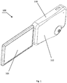
- Fig. 1
- is one embodiment of the disclosed car video recorder with a display;
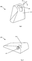
- Fig. 2
- represents a perspective view of the housing of the car video recorder, as illustrated in
Fig. 1 , showing the fastening side of the housing; - Fig. 3
- illustrates a perspective view of the car video recorder mounted onto a windscreen or a glass pane with exploded view;
- Fig. 4a-4c
- represents cross-sections through the housing of the video recorder and the car windscreen;
- Fig. 5
- illustrates other possible forms of the housing; and
- Fig 6
- shows further embodiment of the housing.
- One skilled in the art will readily appreciate that the present invention is well adapted to carry out the objects and obtain the mentioned advantages, as well as those inherent therein. The embodiments described below are not intended to be considered as limitations of the scope of the invention. In the description below the terms "video recorder", "car video recorder", "video recorder apparatus" and "car digital video recorder" denote the same and are used interchangeable.
- The terms "camera" and "video camera" denote the same are used interchangeable.
The terms "optical elements" used herein throughout of the specification refers to such components of the video camera as a lens responsible for directing the optical radiation to image sensor of the camera for providing the sensor with a possibility to generate, from the forwarded optical radiation, digitized images of the events happened around.
The terms "strayed optical radiation", "stray light" used interchangeable herein throughout the specification refer to optical radiation bringing into contact, by either refraction or reflection with the optical elements of the camera out of the defined field of vision or angle of view of the camera. The strayed optical radiation may create, but not necessary, deceptive illusions or parasitic images onto the recorded information or create light patches on the image captured by the camera which lead to occurrence of undesired artifacts in the image.
The video recorder may be accommodated to be mounted to a windscreen or any glass pane, and in the present specification the terms "windscreen" and "glass pane" are used interchangeable. However, for the purposes of simplicity only, the following description is provided with respect to the windscreen.
The main parts of a car digital video recorder are a video camera, a control and processing block, a storage and a display. - Video camera consists of various electronic and optical components known in the art to digitally generate, record and/or transmit the captured information. The components required to implement the video camera may include a flexible integrated circuit board, computing processor, RAM, digital writing and storage medium, optical (image) sensor, optical lens, and the like. It is possible to accommodate the assembly of video camera partially or wholly inside the housing according to different embodiments. The camera through its optical elements (objective, lens) acquires external radiation falling on the image sensor, generates a video signal (video image) which is transferred to the control and processing block. The video camera of the disclosed video recorder may be equipped with a communication module for receiving/transmitting digital information from/to the control and processing block if it is arranged out of the housing of the video recorder.
The control and processing block performs controlling operations of the video recorder, processes the video image acquired by the video camera and generated by its image sensor, may perform compression of the video image for reducing data volume, and transfers the obtained data to the storage for recording to it and/or to a video display. Usually, the storage is of electronic or magnetic type, such as flash-memory, a hard disk or an optical disk and the like, as well known to those skilled in the art.
The display reproduces the image transferred to it from the video camera directly or read out from the storage device. Controls for controlling the operation of the video recorder may be positioned on the display, if the display is of touch-screen type, on the video recorder housing near the display area or may be arranged in the control and processing block. The display may be attached to the housing and be arranged above, below or sideways from the housing. Fixation of the display to the video recorder housing, for example, may provide a possibility of rotation of the display around a vertical axis, if the display is fastened sideways from the housing, or around a horizontal axis, if the display is fastened above or below the housing. Other commonly known kind of attaching the display to the housing should be apparent to a skilled person. Moreover, the display may also be detachable or be fully separated from the video recorder housing. Communications between the display and the video camera and/or the control and processing block are implemented either by wire or wirelessly or by combination thereof. - The car digital video recorder is described below with references to figures, where similar reference positions denote similar elements. It should be noted, that the figures illustrate the video recorder not in the scale.
InFig. 1 an example of a general view of the video recorder (100) which has a housing (110) and a display (101) is illustrated. In one embodiment, the housing has a form of parallelepiped with the rounded off corners and the rounded off edges between sidewalls (facets). However, the video recorder housing may have various forms, for example, rectangular in the plan, oval in the plan, the irregular form, etc. Several possible appearances of the video recorder housing form are provided inFigs. 5 and 6 . The general requirement to the housing is isolating its internal space from stray external light, moisture, dust, etc. and presence of a window only through which the external "useful" radiation can get to the housing interior and hit in the video camera lens. - In the embodiment, where the housing is of parallelepiped form, the size of front side of the housing in any one dimension may be within the range of about 25 - 150 mm, preferable about 30 - 70 mm, while the housing thickness is about 4 - 60 mm, preferable about 10-25 mm. It shall be noted that the sizes of the housing are not limited by the cited numerical values which are presented as examples only and may be set individually, in appropriate manner for each particular realization of the video recorder. Therefore, the indicated sizes in practical realizations may be more or less than are presented above.
- With references to
Fig.2 , the invented car video recorder (100) is shown having the housing (110). Preferably, the housing (110) is fabricated from plastic, metal or alloy material with good mechanical strength properties. Regardless of the material, the housing shall not significantly affect the overall weight of the video recorder to ensure the video recorder is light enough to be attached onto the windscreen or a glass pane without much difficulty and have mechanical strength sufficient to provide integrity of the housing while being detached from the windscreen. - The housing (110) by its sidewalls, including a front side (111) and a back side (112) being at least partially spaced apart at a predetermined distance, defines an enclosed cavity (130) as illustrated in
Figs. 3 and4 , for accommodating therein the video camera and, in some embodiments, the control and processing block. - In general, the front side and the back side are not identical in shape. The back side of the housing may be convex (as shown in
Figs.1 ,4 ,5, and 6 ). In contrast, the front side is substantially flat, and with help of the flat surface of the front side the video recorder may be fastened to the windscreen directly or by additional means. This front side having a substantially flat surface in the present description is also referred to in the description as the fastening side for mounting video recorder housing to the windscreen. The fastening side is designated by a reference position (111) in figures. It should be noted that the fastening side is not indicated inFigs. 5 and 6 .
The convex shape of the back side significantly increases the volume of the defined cavity allowing more components to be accommodating therein. The convex configuration of the back side also creates greater distance in between the front side and at least a part of the back side providing greater flexibility for the disclosed video recorder to adjust the relative position of the optical elements of the video camera within the housing to ensure, for example, the optimal field of vision. The fastening side (111) of the housing has a window (119) of arbitrary form and in some embodiments is closed by a panel from a transparent material, which is flush with the surface of the fastening side. Preferably, the form of the window is a rectangular occupying as much surface area of the fastening side as possible. In other embodiment the window can be left open, thus creating an opening. Nevertheless, in some embodiments, the window (119) in the fastening side (111) of the housing is encompassed by a closed surface of the fastening side.
The external optical radiation denoted inFig.3 as (107), for example, visible light or IR-radiation, passes into the housing through the window only and falls into the optical elements of the video camera. It is important to be noted herein that the present embodiment requires that at least the optical elements of the video camera to be installed within the defined enclosed cavity (130) of the housing (110) and to be protected from entering of the strayed optical radiation inside the housing by the housing sidewalls. Accordingly, optical elements of the camera are arranged to receive optical radiation passing sole through the formed window (119) on the fastening side (111) of the housing and the windscreen (200) to finally land on the optical elements (lens) of the video camera only. - The internal surface of the cavity may be covered with non-reflective paint or non-reflective material. The non-reflective coating absorbs optical radiation entering the cavity through the window and bringing into contact with the internal surface without being reflected inside the cavity. The non-reflective coating further negates unwanted light or optical radiation reflection within the cavity.
- In some embodiments the video recorder has, between the windscreen or a glass pane and the flat surface of the front side of the video recorder housing, a means for mounting the video recorder to the windscreen in detachable manner.
- In one embodiment such means is represented by a gasket (105) in form of pliable sheet from elastic (resilient) material, such as rubber or foamed material. The gasket also has an opening with the form and arrangement substantially coinciding with the form and arrangement of the window (119) in the fastening side (111) of the housing (see
Fig.3 ). Although theFig. 3 shows that the gasket opening has the same size as the window (119) in the fastening side, the gasket opening can be cut off in order to have a some larger size, for example, by 1-3 mm in each direction along the window (opening) plane, so as not to prevent the external radiation inclined under some angle to the lens axis for falling onto the video camera optical elements within the housing. - The gasket has two opposing planar surfaces coated with adhesives to detachably fix on the windscreen and the fastening side of the housing, respectively. A layer of a first adhesive substance for providing attachment of the gasket to the fastening side (111) of the housing of the video recorder is applied on the one planar surface of the gasket (105). A layer of the second adhesive substance is applied on another planar surface, opposite to the first one, of the gasket for fastening the gasket to the windscreen. The first adhesive substance and the second adhesive substance can be differing from each other or identical.
- Thus, the housing (110) of the video recorder by its fastening side (111) is fastened to the windscreen by means of the intermediate gasket (105) on which planar surfaces the first and the second adhesive substances are applied.
- The chemical formulation of the first adhesive substance and the second adhesive substance are not a subject of the present invention. The basic requirement for the adhering properties of these substances consists in that they should hold the weight of the whole recorder in its mounted-to-the-windscreen state without additional assistance of, for example, mechanical, supporting means. I.e. fastening strength of one adhesive substance, applied onto one surface of the gasket, with the windscreen and fastening strength of another adhesive substance, applied onto another surface of the gasket, with the housing should allow to maintain the video recorder in its mounted (operating) state.
- It is preferred that the second adhesive leaves no residues on the windscreen after detachment of the disclosed video recorder from the windscreen.
- Other requirements for the properties of adhesive substances can be transparency, non-toxicity, preservation of adhesion properties for a long time, etc.
- The gasket (105) of an elastic material is described referring to
Fig.4a , where the sectional view along the line A-A (shown inFig.3 ) through the housing of the video recorder attached in its mounted operating state to the windscreen is illustrated. The windscreen can have a small curvature which is given while manufacturing the windscreen for the purpose of providing aerodynamic properties to the moving car. This curvature might not provide to the flat fastening side of the video recorder housing a possibility to be in close contact with the windscreen over the whole surface area of the fastening side. In one embodiment, pliability of the gasket inserted between the windscreen and the housing allows the housing to universally fix onto windscreen of various dimension and curvature and therefore allows for the elimination of this drawback since, owing to its elastic properties, in the mounted state of the video recorder to the windscreen a middle part and edge parts of the gasket have different degree of compression (designated as a and b inFig.4 ) to conform the curvature of the windscreen. The thickness of the gasket (105) may be from within 1 to 8 mm, preferable within the range of 2 to 4 mm. Although inFig.4 the sectional views of the video recorder are shown along the line A-A directed horizontally, it should be apparent that the conformation remains consistent across the gasket (105) along any another direction. Thus, the gasket shall have the cross-section providing close contact of the housing with the windscreen. - According to another preferable embodiment, the fastening side of the housing of the video recorder has the form conformed the windscreen curvature. In this embodiment, the gasket may not be required, and one adhesive substance for applying on the fastening side (111) of the housing for attaching the video recorder directly to the windscreen is required only. Requirements to properties of this adhesive substance are similar to those described above.
- According to one more preferable embodiment, the means for mounting the video recorder to the windscreen may be the gasket (105) in combination with a plate (180) having a form in a plan view preferably coinciding with the form of the fastening side in a plan view. The plate is physically rigid and is made from plastic, metal, etc. and also has an opening in the form and arrangement substantially coinciding with those of the window in the housing fastening side. The plate has two opposing planar surfaces on one of which is attached the gasket with the adhesives, to fix onto the windscreen, and another planar surface of the plate is provided with a first locking profile. In this case the housing has the counterpart locking profile being fashioned to detachably interlock with the first locking profile to mount the housing to the plate in the male-female locking manner. The thickness of the plate is within the range from 1 to 8 mm, however, any other values for the thickness may be used.
The mentioned structure is represented in more details inFig.4b and 4c .
Fig. 4b shows the plate (180) having two opposing planar surfaces, one fabricated with a pair of male locking profile (184) and another fixed to the gasket (105) fastened to the windscreen. The male locking profile (184) inFig. 4b in this embodiment is at least one pair ball structures. Each ball structure has one side integrated with the plate planar surface. Correspondingly, the pair of compatible spherical hollows which serve as the female locking profile (185), is engraved at the fastening side (111) of the housing (110). Each hollow has opening slightly smaller than the diameter of the ball structures. The ball structures preferably possesses good elasticity which allows the ball structure to be temporarily deformed while being inserted into or removed out of the holes through the smaller opening. More preferably, the spherical hollow may be slightly smaller in size than the ball structure to facilitate snug engagement of the male (184) and female locking profiles (185). Such fastening should provide reliable fixing of the video recorder in its operating state to the windscreen without self-detaching. - In one more embodiment, the ball structures are replaced by at least one pair of parallel ridges extending longitudinally on the plate (180), and the fastening side (111) has corresponding pair(s) of corresponding grooves to slidably interlock with the ridges. The ridges should not be necessarily having a round cross-section, they might be in L-form or any another form which allows tight attachment of the housing (110) to the plate (180).
Fig. 4b can be considered as a cross-section of such ridges / grooves. Further embodiment illustrated inFig. 4c , the plate (180) has two L-shaped opposing lateral latches, as the male locking profile (184), to be slidably engaged by compatible protrusions with two opposing grooves, as the female locking profile (185), located on the fastening side (111) of the housing (110). As a result of the sliding the fastening side window matches the plate opening for the realization of mounting the housing for the operation of the disclosed video recorder (100). - When fixing the plate (180) with the housing (110) is made by the lateral latches entering into corresponding grooves in the housing thus allowing to fix the housing (110) to the plate (180), the detachment of the housing from the plate is performed by bending back the lateral latches.
- In further embodiment, the means for fixing the plate (180) to the housing (110) of the video recorder, instead of several elements of the male locking profile, may have the male locking profile in the form of single continuous ridge extending along all periphery edge of the plate (180). The mentioned ridge engaging with a counterpart groove similarly extending along all periphery of the housing. In such case the plate with the ridge may be considered as a "basin" for inserting the housing by its grooves into it, and the material of the ridge should have corresponding elastic properties allowing unbending the ridge for inserting in and removing the housing into / from the "basin".
Here, it is necessary to notice that the male (184) and female (185) locking profiles are interchangeable in between the plate (180) and the fastening side (111) of the housing (110). In this case the thickness of the plate (180) shall have the size allowing fabricating therein a corresponding locking profile, for example, hollows for ball structures, to provide secure of the plate with housing. By means of the structure exemplary illustrated on any ofFig.4a, 4b, 4c , the possibility of intended removal of the housing of the video recorder from the windscreen is provided. In the embodiment illustrated inFig.4a , one can demand, in some cases, replacement of the gasket (105) with a new one in view of damage of the former after repetitive cycles of attachment and detachment, in other cases the detachable joining without damage of the gasket (105) is made due to the adhesive properties between the gasket and the windscreen. Besides of this, in another embodiment the housing (110) may be hingeably secured to the plate (180) such that the housing is able to rotatably switch from a first position, where the fastening side is abutted onto the plate (180), to a second position, which is 90 to 240 degree different from the first position, where the fastening side is not contacted with the plate. The hinge secure may be provided by an axial fixture at edge of the plate for enabling pivoting motion of the housing relatively the plate. The axial fixture may be provided at a left or right edge of the plate or at an upper or a lower edge thereof. Such construction facilitates movement of the housing (110) from the first position to the second position in which the optical elements (120) enable the video camera to record situation around the camera, for example, the situation of the interior cabin of the vehicle, while the plate remains fastened to the windscreen via the gasket.
By means of providing the housing in the form mentioned above the enclosed cavity defined by the housing walls is created. In the cavity within the housing the video camera optical elements (seeFig.3 ) are provided. While the field of vision of the video camera in the known video recorders is usually directed away from the housing where the video camera is arranged, without passing through the interior of the recorder housing, in contrast, the video camera has a field of vision directed inwardly the housing (110) and is oriented towards the window in the fastening side. Thus, the video camera is arranged in such way that external radiation, for example visible or IR-light passing from the outside the car through the windscreen, gets on the optical elements of the video camera only through the window (119) in the fastening side of the video recorder housing. Thus, the video camera receives the external radiation, generates an image from the radiation by methods known in the art and either records the image in the storage device or, if the recording function is not currently active, transmits the image directly to the display of the video recorder for displaying it to a user, for example, to the car driver in real-time.
The mechanism of mounting the video camera within the housing cavity is not a subject of the present invention. The video camera may be fixedly secured to the back side opposite to the fastening side of the housing, may be fixed within the housing by supports attached to the lateral sides of the housing, etc.
The range of viewing angle or field of vision of the disclosed video recorder (100) depends on the constructive implementation of the optical elements of the video camera and physical dimensions of the housing (110), in particular, the sizes of the window (119) at the fastening side (111). Additionally or separately, the field of vision of the optical elements may be dependent on the relative distance between the front window (119) and the optical element especially in the condition where the fastening side (111) of the housing is partly overlapping with the field of vision of the camera. The viewing angle of the video recorder employed in the present embodiment may be within the range of ±0.5 to ±89.5 degrees relatively the optical axis of the video camera, preferable within the range of from ±30 to ±70 degrees and the most preferable within the range of from ±35 to ±60 degrees horizontally. The same numerical values may be provided vertically for the viewing angle of the video recorder.
In some embodiments the mounting mechanism provides the video camera with a possibility to be rotated relatively an axis being normal to the optical axis of the video camera, for example, as indicated as arrow "d" inFig.5 or Fig.6 . In the embodiments the camera has a possibility of rotation by means of a handle (135) attached to the camera or its optical elements and extended from the back side of the housing, as illustrated inFig.5 . (It should be noted that the recorder housing is illustrated inFigs 5 and 6 not in the state of fastening to the windscreen, the mounted state of the housing corresponds to one where the back side (112) is situated from below.) The user, for example, the car driver may grasp the camera handle (135) and pull it down or up thus causing turn of the camera round the axis normal to the optical axis in order to change up or down, respectively, the direction of the camera optical axis. The turn of the video camera may be similarly performed by a wheel (137), as indicated inFig. 6 by the arrow "d". In further embodiment the user has a possibility to move the camera position within the housing along the camera optical axis either toward the windscreen or away from it also by grasp the camera handle (135), as indicated by arrow "c" inFig.5 . The constructive implementation of the mechanism providing such displacement of the camera along its optical axis should be apparently construed by those skilled in the art. - Further, the camera of the present embodiment can perceive visible light or infra-red radiation. The type of optical radiation perceptible relies on the sensor of the camera. The image sensor of the disclosed embodiment is preferably capable of generating image based on optical radiation of visible or infrared light. Apart from that, the optical elements of the present embodiment are placed within the cavity of the housing (110) to avoid strayed optical radiation while conventional vehicle video recording systems generally have the optical elements protruded outwardly from the housing. Although the present embodiment illustrates (for example, in
Fig.3 ) that the optical axis of the optical element forms substantial a right angle with the windscreen surface, one skilled in the art shall recognize that the basic principles of the present embodiment may be applied for the like video recorders fastened to the windscreen having optical elements inclined at some angle different from 90° in relative to the windscreen. The construction of the video recorder may comprise the video camera optical axis retained approximately horizontally whereas the windscreen is tilted about horizon, and therefore, the video recorder viewing angle may be restricted from below the optical axis to a greater extent then from above.
The basic advantage of the present video recorder consists in placement of the video camera within the housing autonomously fixed to the windscreen in such way that the field of vision of the video camera is directed to the windscreen through the enclosed, perhaps except the window, cavity within the housing, wherein sidewalls of the housing prevent hitting light beams from stray light sources onto the video camera lens. In other words, stray light from the sources which are not in the field of vision of the camera, being reflected from the windscreen cannot fall onto the video camera lens. It allows for avoidance of occurrence, for example, parasitic light patches which can lead to distortion of details of the image generated by the video camera.
Video recorder design according to the present invention provides, besides of the advantage specified above, protection against hitting the fog into the housing or against sedimentation on the camera lens of dust or distortion of the images with cigarette smoke which may be present in the car interior, prevents occurrence of a moisture in the form of droplets on the lens when temperature suddenly changes, for example, upon the opening of a car door in cold temperature conditions, for example, in winter), etc. Preferably, the cavity is substantially hermetic against smoke, water vapor and/or dust upon mounting the housing onto the windscreen. For example, smoke of cigarette inside the vehicle may make way into the cavity blocking or deflecting the optical radiation if the cavity was not properly sealed. Likewise, water vapor inside the vehicle may condense onto the lens in the absence of proper sealing at the window. The sealing against smoke, water vapor and/or dust is preferably attained by fastening the video recorder housing as mentioned in the above description. Optionally, the window is further shielded with a transparent material to reinforce the sealing against the external agents. The transparent material preferably has refractive index substantially equal to that of air to ensure the optical radiation passed through thereof free from significant modification.
The inventive video recorder has usual for such devices means for image generating (such as a CCD array), processing (such as a video processor) and storing (such as a memory) intermediate and/or final information, and can also have the communication means for receiving/transmitting instructions or messages transferred by wires or in a wirelessly manner into/from the video recorder, etc.
The power supply for the video recorder may be provided from a built-in battery or external power supply unit connected to the video recorder by wires and energizing all electronic components of the video recorder. If the power is supplied from the built-in battery the housing has a corresponding compartment in which such battery is provided, if the power is supplied from the external power grid the housing should have corresponding sockets for connection it to such power supply.
It is to be understood that the present invention may be embodied in other specific forms and is not limited to the sole embodiment described above. Although the present invention was described relatively to the car video registers, those skilled in the art can readily recognize that the basic principles of the invention may be applied for surveillance cameras, video monitoring systems operating in gaseous and liquid environments including hostile and reactive environment, in the systems for monitoring technological process, in bathyscaphes, submarines, etc. Therefore, the scope of the present invention should be defined by the accompanied claims but not the particular examples described in the present specification.
Claims (5)
- A video recorder (100) configured to be removable mounted on a windscreen (200) or a glass pane, the video recorder comprising:a housing (110) having sidewalls, including a front side (111) and a back side (112), forming an enclosed internal cavity (130) within the housing (110), the front side (111) being substantially flat and having a window (119) through which only an external optical radiation from outside passes into the enclosed internal cavity (130), the housing is configured for removable attaching onto the windscreen (200) or the glass pane,a video camera arranged within the internal enclosed cavity, wherein the optical axis of the video camera lens is oriented toward the window in such way that allows the video camera to acquire the optical radiation passed into the housing sole through the window and fallen onto the video camera image sensor, for obtaining an image signal from the acquired external optical radiation,a gasket (105) of an elastic or resilient material, characterized in that the video recorder further comprisesa firm plate (180), wherein the gasket (105) and the plate (180) each has an opening substantially coinciding in the form and arrangement with the form and arrangement of the window (119) in the front side (111) of the video recorder housing (110) for matching the openings and the window with each other in the operating state of the video recorder, wherein the gasket (105) is attached to the plate (180) by a first adhesive substance applied on a first planar surface of the gasket,wherein the video recorder is fastened to the windscreen (200) through the gasket (105) by means of a second adhesive substance applied on a second planar surface, opposite to the first planar surface of the gasket (105), thereby the housing (110) of the video recorder is fastened to the plate (180) in detachable manner,wherein fastening of the housing (110) in detachable manner to the plate (180) is implemented by means of a counterpart locking profile (184, 185) being a single ridge located on the plate side along the whole periphery of the plate, engaging with reciprocal groove in the housing.
- The video recorder according to claim 1, wherein the plate (180) having a form in a plan view coinciding with the form of the front side (111) of the housing in a plan view.
- The video recorder according to claim 1 or claim 2, wherein the plate (180) has two opposing planar surfaces, wherein the gasket is attached on the first planar surface and wherein the second planar surface is provided with the locking profile (184, 185).
- The video recorder according to claim 1, wherein the external optical radiation is at least one of visible light or IR-radiation.
- The video recorder according to claim 1, wherein the window on the front side of the housing is surrounded by a closed surface of the mentioned front side.
Applications Claiming Priority (1)
| Application Number | Priority Date | Filing Date | Title |
|---|---|---|---|
| SG2013056700A SG2013056700A (en) | 2013-07-23 | 2013-07-23 | Digital video recorder |
Publications (2)
| Publication Number | Publication Date |
|---|---|
| EP2830304A1 EP2830304A1 (en) | 2015-01-28 |
| EP2830304B1 true EP2830304B1 (en) | 2018-08-08 |
Family
ID=54396368
Family Applications (1)
| Application Number | Title | Priority Date | Filing Date |
|---|---|---|---|
| EP13005362.2A Not-in-force EP2830304B1 (en) | 2013-07-23 | 2013-11-13 | Video recorder |
Country Status (13)
| Country | Link |
|---|---|
| US (1) | US20150029336A1 (en) |
| EP (1) | EP2830304B1 (en) |
| JP (1) | JP6399379B2 (en) |
| KR (1) | KR102198992B1 (en) |
| CN (1) | CN104349103B (en) |
| AR (1) | AR097019A1 (en) |
| AU (1) | AU2014203732A1 (en) |
| CA (1) | CA2857411A1 (en) |
| IN (1) | IN2014DE02071A (en) |
| PH (1) | PH12014000187A1 (en) |
| SG (1) | SG2013056700A (en) |
| TW (1) | TW201522126A (en) |
| ZA (1) | ZA201405419B (en) |
Families Citing this family (17)
| Publication number | Priority date | Publication date | Assignee | Title |
|---|---|---|---|---|
| DE202014100544U1 (en) * | 2014-01-10 | 2014-06-02 | Michael Ali Kilic | Rifle control and aiming camera system |
| SE537665C2 (en) * | 2014-01-28 | 2015-09-29 | Scania Cv Ab | Mounting arrangement for mounting a component element on the vehicle windshield |
| US10423028B2 (en) * | 2014-04-22 | 2019-09-24 | E Ink Holdings Inc. | Display apparatus |
| JP6642432B2 (en) * | 2014-07-31 | 2020-02-05 | ソニー株式会社 | Information processing apparatus, information processing method, and image display system |
| US9667871B2 (en) * | 2015-03-20 | 2017-05-30 | Motorola Mobility Llc | Remote imaging in modular cellular phone |
| DE102015110760A1 (en) * | 2015-07-03 | 2017-01-05 | Mathias Jatzlauk | Gesture control system for visualization devices |
| USD827762S1 (en) * | 2015-10-29 | 2018-09-04 | Did, Inc. | Stun gun |
| CN105488865A (en) * | 2015-11-30 | 2016-04-13 | 小米科技有限责任公司 | Automobile data recorder and reflection shielding means |
| CN105631978A (en) * | 2016-03-31 | 2016-06-01 | 必行科技(北京)有限公司 | Rearview mirror automobile data recorder |
| CN109070704B (en) * | 2016-04-27 | 2021-10-08 | Agc株式会社 | Window member and window glass for vehicle |
| CN107016748A (en) * | 2017-05-10 | 2017-08-04 | 寅家电子科技(上海)有限公司 | Drive recorder |
| CN107231516A (en) * | 2017-07-27 | 2017-10-03 | 重庆万建电子工程有限责任公司重庆第分公司 | Band scrapes the dome-type camera of grey structure |
| TWI660607B (en) * | 2017-11-17 | 2019-05-21 | 中華電信股份有限公司 | Method and system for monitoring road pavement quality |
| FR3079054B1 (en) * | 2018-03-13 | 2020-02-14 | Eurekam | DEVICE FOR TAKING PICTURE AND SYSTEM SUITABLE FOR THE SECURE DEVELOPMENT OF DRUG PREPARATIONS |
| FR3079055B1 (en) * | 2018-03-13 | 2021-01-08 | Eurekam | SHOOTING DEVICE AND SYSTEM FOR THE SAFE PREPARATION OF DRUG PREPARATIONS |
| DE102019111512B4 (en) * | 2019-05-03 | 2022-09-01 | Mekra Lang Gmbh & Co. Kg | Vision system and mirror replacement system for a vehicle |
| JP2022163481A (en) * | 2021-04-14 | 2022-10-26 | 株式会社デンソー | Occupant monitoring system |
Citations (3)
| Publication number | Priority date | Publication date | Assignee | Title |
|---|---|---|---|---|
| US20040119881A1 (en) * | 2002-12-20 | 2004-06-24 | Matko Mark A. | Universal camera bracket that allows 180 degree of pitch adjustment |
| DE102009018515A1 (en) * | 2009-04-23 | 2010-11-11 | Bury Sp.Z.O.O | Camera apparatus for use in a motor vehicle |
| US8400560B1 (en) * | 2012-02-23 | 2013-03-19 | E-Lead Electronic Co., Ltd. | Viewing angle adjustable vehicle camera device |
Family Cites Families (15)
| Publication number | Priority date | Publication date | Assignee | Title |
|---|---|---|---|---|
| JP2920653B2 (en) | 1990-03-15 | 1999-07-19 | アイシン精機株式会社 | In-vehicle imaging device |
| DE19647200C1 (en) * | 1996-11-15 | 1998-01-08 | Kostal Leopold Gmbh & Co Kg | Roof module casing for motor-vehicle e.g. for rain-dependent windscreen wiper control |
| US6326613B1 (en) | 1998-01-07 | 2001-12-04 | Donnelly Corporation | Vehicle interior mirror assembly adapted for containing a rain sensor |
| US6389340B1 (en) | 1998-02-09 | 2002-05-14 | Gary A. Rayner | Vehicle data recorder |
| US6170955B1 (en) * | 1998-02-27 | 2001-01-09 | Iteris, Inc. | Vehicle mounted optical assembly |
| JP2002341432A (en) * | 2001-05-16 | 2002-11-27 | Murakami Corp | Imaging device |
| DE10237607B4 (en) * | 2002-08-16 | 2007-01-25 | Hella Kgaa Hueck & Co. | Camera arrangement for motor vehicles |
| JP2004075033A (en) * | 2002-08-17 | 2004-03-11 | Hisao Saito | On-vehicle device for automatically video image picking up and recording car accident, and recording method therefor |
| DE102004024735A1 (en) * | 2004-05-19 | 2005-12-15 | Leopold Kostal Gmbh & Co Kg | Camera arrangement for a motor vehicle |
| DE102004039464A1 (en) * | 2004-08-14 | 2006-02-23 | Robert Bosch Gmbh | Imaging system |
| JP5062977B2 (en) * | 2005-07-01 | 2012-10-31 | 株式会社堀場製作所 | Driving recorder |
| US20070064108A1 (en) * | 2005-09-16 | 2007-03-22 | Haler Robert D | Rear view mirror with integrated video system |
| US8520069B2 (en) * | 2005-09-16 | 2013-08-27 | Digital Ally, Inc. | Vehicle-mounted video system with distributed processing |
| US7893958B1 (en) | 2006-04-03 | 2011-02-22 | D Agostino Daniel M | Vehicle video recorder |
| JP2012076691A (en) * | 2010-10-05 | 2012-04-19 | Toyota Motor Corp | Vehicle camera unit, vehicle camera attachment tool, and method of attaching vehicle camera |
-
2013
- 2013-07-23 SG SG2013056700A patent/SG2013056700A/en unknown
- 2013-11-13 EP EP13005362.2A patent/EP2830304B1/en not_active Not-in-force
- 2013-12-04 KR KR1020130149838A patent/KR102198992B1/en active IP Right Grant
- 2013-12-12 JP JP2013256679A patent/JP6399379B2/en active Active
- 2013-12-17 US US14/108,608 patent/US20150029336A1/en not_active Abandoned
- 2013-12-31 CN CN201310749268.0A patent/CN104349103B/en active Active
-
2014
- 2014-06-27 TW TW103122458A patent/TW201522126A/en unknown
- 2014-06-30 PH PH12014000187A patent/PH12014000187A1/en unknown
- 2014-07-08 AU AU2014203732A patent/AU2014203732A1/en not_active Abandoned
- 2014-07-22 IN IN2071DE2014 patent/IN2014DE02071A/en unknown
- 2014-07-22 CA CA2857411A patent/CA2857411A1/en not_active Abandoned
- 2014-07-22 AR ARP140102723A patent/AR097019A1/en unknown
- 2014-07-23 ZA ZA2014/05419A patent/ZA201405419B/en unknown
Patent Citations (3)
| Publication number | Priority date | Publication date | Assignee | Title |
|---|---|---|---|---|
| US20040119881A1 (en) * | 2002-12-20 | 2004-06-24 | Matko Mark A. | Universal camera bracket that allows 180 degree of pitch adjustment |
| DE102009018515A1 (en) * | 2009-04-23 | 2010-11-11 | Bury Sp.Z.O.O | Camera apparatus for use in a motor vehicle |
| US8400560B1 (en) * | 2012-02-23 | 2013-03-19 | E-Lead Electronic Co., Ltd. | Viewing angle adjustable vehicle camera device |
Also Published As
| Publication number | Publication date |
|---|---|
| KR102198992B1 (en) | 2021-01-06 |
| ZA201405419B (en) | 2016-10-26 |
| IN2014DE02071A (en) | 2015-08-28 |
| RU2013154231A (en) | 2015-06-10 |
| AU2014203732A1 (en) | 2015-02-12 |
| TW201522126A (en) | 2015-06-16 |
| AR097019A1 (en) | 2016-02-10 |
| US20150029336A1 (en) | 2015-01-29 |
| SG2013056700A (en) | 2015-02-27 |
| CN104349103A (en) | 2015-02-11 |
| EP2830304A1 (en) | 2015-01-28 |
| CN104349103B (en) | 2019-07-30 |
| PH12014000187A1 (en) | 2016-01-11 |
| KR20150011743A (en) | 2015-02-02 |
| JP6399379B2 (en) | 2018-10-03 |
| JP2015023571A (en) | 2015-02-02 |
| CA2857411A1 (en) | 2015-01-23 |
Similar Documents
| Publication | Publication Date | Title |
|---|---|---|
| EP2830304B1 (en) | Video recorder | |
| US20170355312A1 (en) | Interior rearview mirror assembly with full screen video display | |
| US6175300B1 (en) | Blind spot viewing system | |
| JP3684522B2 (en) | Electronic camera that captures images through glass | |
| KR100909368B1 (en) | Monitor camera mounting structure for vehicle | |
| US20150334354A1 (en) | Mirror element for vehicle | |
| US8330815B2 (en) | Vehicle-mounted camera system | |
| US7365300B2 (en) | Rear vision system | |
| CN114555421B (en) | Rotatable external mirror with imager assembly | |
| US20190344717A1 (en) | Rear view device with mult-piece backing plate | |
| CN112009389A (en) | Vehicle-mounted vision processing equipment, system, mounting method, processing method and vehicle | |
| JP6643585B2 (en) | Vehicle rearview mirror | |
| JP7475045B2 (en) | Vehicle rearview mirror | |
| RU2588282C2 (en) | Digital video recorder | |
| US11523032B2 (en) | Optical image sensing device for a motor vehicle | |
| CN209987855U (en) | 360-degree panoramic camera device for passenger car | |
| MX2014008870A (en) | Digital video recorder. | |
| RU2636630C1 (en) | Digital video recorder and method of its installation | |
| JP2005309051A (en) | Optical filter holding apparatus | |
| CN213705308U (en) | Vehicle-mounted binocular intelligent automobile vision mechanism | |
| RU204346U1 (en) | External antenna module with extended functionality | |
| JP7462978B2 (en) | Vehicle rearview mirror | |
| CN109509275A (en) | A kind of thermal imaging rearview mirror automobile data recorder | |
| CN205292463U (en) | Can hide structure at vehicle event data recorder of rear -view mirror | |
| GB2510622A (en) | Vehicle camera apparatus |
Legal Events
| Date | Code | Title | Description |
|---|---|---|---|
| 17P | Request for examination filed |
Effective date: 20131113 |
|
| AK | Designated contracting states |
Kind code of ref document: A1 Designated state(s): AL AT BE BG CH CY CZ DE DK EE ES FI FR GB GR HR HU IE IS IT LI LT LU LV MC MK MT NL NO PL PT RO RS SE SI SK SM TR |
|
| AX | Request for extension of the european patent |
Extension state: BA ME |
|
| PUAI | Public reference made under article 153(3) epc to a published international application that has entered the european phase |
Free format text: ORIGINAL CODE: 0009012 |
|
| R17P | Request for examination filed (corrected) |
Effective date: 20150522 |
|
| RBV | Designated contracting states (corrected) |
Designated state(s): AL AT BE BG CH CY CZ DE DK EE ES FI FR GB GR HR HU IE IS IT LI LT LU LV MC MK MT NL NO PL PT RO RS SE SI SK SM TR |
|
| 17Q | First examination report despatched |
Effective date: 20151214 |
|
| GRAP | Despatch of communication of intention to grant a patent |
Free format text: ORIGINAL CODE: EPIDOSNIGR1 |
|
| INTG | Intention to grant announced |
Effective date: 20180214 |
|
| GRAJ | Information related to disapproval of communication of intention to grant by the applicant or resumption of examination proceedings by the epo deleted |
Free format text: ORIGINAL CODE: EPIDOSDIGR1 |
|
| GRAR | Information related to intention to grant a patent recorded |
Free format text: ORIGINAL CODE: EPIDOSNIGR71 |
|
| GRAS | Grant fee paid |
Free format text: ORIGINAL CODE: EPIDOSNIGR3 |
|
| GRAA | (expected) grant |
Free format text: ORIGINAL CODE: 0009210 |
|
| INTC | Intention to grant announced (deleted) | ||
| AK | Designated contracting states |
Kind code of ref document: B1 Designated state(s): AL AT BE BG CH CY CZ DE DK EE ES FI FR GB GR HR HU IE IS IT LI LT LU LV MC MK MT NL NO PL PT RO RS SE SI SK SM TR |
|
| INTG | Intention to grant announced |
Effective date: 20180702 |
|
| REG | Reference to a national code |
Ref country code: GB Ref legal event code: FG4D |
|
| REG | Reference to a national code |
Ref country code: CH Ref legal event code: EP Ref country code: AT Ref legal event code: REF Ref document number: 1028394 Country of ref document: AT Kind code of ref document: T Effective date: 20180815 |
|
| REG | Reference to a national code |
Ref country code: IE Ref legal event code: FG4D |
|
| REG | Reference to a national code |
Ref country code: DE Ref legal event code: R096 Ref document number: 602013041456 Country of ref document: DE |
|
| REG | Reference to a national code |
Ref country code: NL Ref legal event code: MP Effective date: 20180808 |
|
| REG | Reference to a national code |
Ref country code: LT Ref legal event code: MG4D |
|
| REG | Reference to a national code |
Ref country code: AT Ref legal event code: MK05 Ref document number: 1028394 Country of ref document: AT Kind code of ref document: T Effective date: 20180808 |
|
| PG25 | Lapsed in a contracting state [announced via postgrant information from national office to epo] |
Ref country code: NO Free format text: LAPSE BECAUSE OF FAILURE TO SUBMIT A TRANSLATION OF THE DESCRIPTION OR TO PAY THE FEE WITHIN THE PRESCRIBED TIME-LIMIT Effective date: 20181108 Ref country code: GR Free format text: LAPSE BECAUSE OF FAILURE TO SUBMIT A TRANSLATION OF THE DESCRIPTION OR TO PAY THE FEE WITHIN THE PRESCRIBED TIME-LIMIT Effective date: 20181109 Ref country code: NL Free format text: LAPSE BECAUSE OF FAILURE TO SUBMIT A TRANSLATION OF THE DESCRIPTION OR TO PAY THE FEE WITHIN THE PRESCRIBED TIME-LIMIT Effective date: 20180808 Ref country code: BG Free format text: LAPSE BECAUSE OF FAILURE TO SUBMIT A TRANSLATION OF THE DESCRIPTION OR TO PAY THE FEE WITHIN THE PRESCRIBED TIME-LIMIT Effective date: 20181108 Ref country code: SE Free format text: LAPSE BECAUSE OF FAILURE TO SUBMIT A TRANSLATION OF THE DESCRIPTION OR TO PAY THE FEE WITHIN THE PRESCRIBED TIME-LIMIT Effective date: 20180808 Ref country code: RS Free format text: LAPSE BECAUSE OF FAILURE TO SUBMIT A TRANSLATION OF THE DESCRIPTION OR TO PAY THE FEE WITHIN THE PRESCRIBED TIME-LIMIT Effective date: 20180808 Ref country code: AT Free format text: LAPSE BECAUSE OF FAILURE TO SUBMIT A TRANSLATION OF THE DESCRIPTION OR TO PAY THE FEE WITHIN THE PRESCRIBED TIME-LIMIT Effective date: 20180808 Ref country code: IS Free format text: LAPSE BECAUSE OF FAILURE TO SUBMIT A TRANSLATION OF THE DESCRIPTION OR TO PAY THE FEE WITHIN THE PRESCRIBED TIME-LIMIT Effective date: 20181208 Ref country code: FI Free format text: LAPSE BECAUSE OF FAILURE TO SUBMIT A TRANSLATION OF THE DESCRIPTION OR TO PAY THE FEE WITHIN THE PRESCRIBED TIME-LIMIT Effective date: 20180808 Ref country code: LT Free format text: LAPSE BECAUSE OF FAILURE TO SUBMIT A TRANSLATION OF THE DESCRIPTION OR TO PAY THE FEE WITHIN THE PRESCRIBED TIME-LIMIT Effective date: 20180808 Ref country code: PL Free format text: LAPSE BECAUSE OF FAILURE TO SUBMIT A TRANSLATION OF THE DESCRIPTION OR TO PAY THE FEE WITHIN THE PRESCRIBED TIME-LIMIT Effective date: 20180808 |
|
| PG25 | Lapsed in a contracting state [announced via postgrant information from national office to epo] |
Ref country code: HR Free format text: LAPSE BECAUSE OF FAILURE TO SUBMIT A TRANSLATION OF THE DESCRIPTION OR TO PAY THE FEE WITHIN THE PRESCRIBED TIME-LIMIT Effective date: 20180808 Ref country code: LV Free format text: LAPSE BECAUSE OF FAILURE TO SUBMIT A TRANSLATION OF THE DESCRIPTION OR TO PAY THE FEE WITHIN THE PRESCRIBED TIME-LIMIT Effective date: 20180808 Ref country code: AL Free format text: LAPSE BECAUSE OF FAILURE TO SUBMIT A TRANSLATION OF THE DESCRIPTION OR TO PAY THE FEE WITHIN THE PRESCRIBED TIME-LIMIT Effective date: 20180808 |
|
| PG25 | Lapsed in a contracting state [announced via postgrant information from national office to epo] |
Ref country code: RO Free format text: LAPSE BECAUSE OF FAILURE TO SUBMIT A TRANSLATION OF THE DESCRIPTION OR TO PAY THE FEE WITHIN THE PRESCRIBED TIME-LIMIT Effective date: 20180808 Ref country code: ES Free format text: LAPSE BECAUSE OF FAILURE TO SUBMIT A TRANSLATION OF THE DESCRIPTION OR TO PAY THE FEE WITHIN THE PRESCRIBED TIME-LIMIT Effective date: 20180808 Ref country code: CZ Free format text: LAPSE BECAUSE OF FAILURE TO SUBMIT A TRANSLATION OF THE DESCRIPTION OR TO PAY THE FEE WITHIN THE PRESCRIBED TIME-LIMIT Effective date: 20180808 Ref country code: EE Free format text: LAPSE BECAUSE OF FAILURE TO SUBMIT A TRANSLATION OF THE DESCRIPTION OR TO PAY THE FEE WITHIN THE PRESCRIBED TIME-LIMIT Effective date: 20180808 Ref country code: IT Free format text: LAPSE BECAUSE OF FAILURE TO SUBMIT A TRANSLATION OF THE DESCRIPTION OR TO PAY THE FEE WITHIN THE PRESCRIBED TIME-LIMIT Effective date: 20180808 |
|
| REG | Reference to a national code |
Ref country code: DE Ref legal event code: R097 Ref document number: 602013041456 Country of ref document: DE |
|
| PG25 | Lapsed in a contracting state [announced via postgrant information from national office to epo] |
Ref country code: SK Free format text: LAPSE BECAUSE OF FAILURE TO SUBMIT A TRANSLATION OF THE DESCRIPTION OR TO PAY THE FEE WITHIN THE PRESCRIBED TIME-LIMIT Effective date: 20180808 Ref country code: SM Free format text: LAPSE BECAUSE OF FAILURE TO SUBMIT A TRANSLATION OF THE DESCRIPTION OR TO PAY THE FEE WITHIN THE PRESCRIBED TIME-LIMIT Effective date: 20180808 Ref country code: DK Free format text: LAPSE BECAUSE OF FAILURE TO SUBMIT A TRANSLATION OF THE DESCRIPTION OR TO PAY THE FEE WITHIN THE PRESCRIBED TIME-LIMIT Effective date: 20180808 |
|
| REG | Reference to a national code |
Ref country code: DE Ref legal event code: R119 Ref document number: 602013041456 Country of ref document: DE |
|
| PLBE | No opposition filed within time limit |
Free format text: ORIGINAL CODE: 0009261 |
|
| STAA | Information on the status of an ep patent application or granted ep patent |
Free format text: STATUS: NO OPPOSITION FILED WITHIN TIME LIMIT |
|
| REG | Reference to a national code |
Ref country code: CH Ref legal event code: PL |
|
| 26N | No opposition filed |
Effective date: 20190509 |
|
| GBPC | Gb: european patent ceased through non-payment of renewal fee |
Effective date: 20181113 |
|
| PG25 | Lapsed in a contracting state [announced via postgrant information from national office to epo] |
Ref country code: LU Free format text: LAPSE BECAUSE OF NON-PAYMENT OF DUE FEES Effective date: 20181113 Ref country code: MC Free format text: LAPSE BECAUSE OF FAILURE TO SUBMIT A TRANSLATION OF THE DESCRIPTION OR TO PAY THE FEE WITHIN THE PRESCRIBED TIME-LIMIT Effective date: 20180808 |
|
| REG | Reference to a national code |
Ref country code: BE Ref legal event code: MM Effective date: 20181130 |
|
| REG | Reference to a national code |
Ref country code: IE Ref legal event code: MM4A |
|
| PG25 | Lapsed in a contracting state [announced via postgrant information from national office to epo] |
Ref country code: LI Free format text: LAPSE BECAUSE OF NON-PAYMENT OF DUE FEES Effective date: 20181130 Ref country code: SI Free format text: LAPSE BECAUSE OF FAILURE TO SUBMIT A TRANSLATION OF THE DESCRIPTION OR TO PAY THE FEE WITHIN THE PRESCRIBED TIME-LIMIT Effective date: 20180808 Ref country code: CH Free format text: LAPSE BECAUSE OF NON-PAYMENT OF DUE FEES Effective date: 20181130 |
|
| PG25 | Lapsed in a contracting state [announced via postgrant information from national office to epo] |
Ref country code: IE Free format text: LAPSE BECAUSE OF NON-PAYMENT OF DUE FEES Effective date: 20181113 Ref country code: DE Free format text: LAPSE BECAUSE OF NON-PAYMENT OF DUE FEES Effective date: 20190601 Ref country code: FR Free format text: LAPSE BECAUSE OF NON-PAYMENT OF DUE FEES Effective date: 20181130 |
|
| PG25 | Lapsed in a contracting state [announced via postgrant information from national office to epo] |
Ref country code: BE Free format text: LAPSE BECAUSE OF NON-PAYMENT OF DUE FEES Effective date: 20181130 |
|
| PG25 | Lapsed in a contracting state [announced via postgrant information from national office to epo] |
Ref country code: GB Free format text: LAPSE BECAUSE OF NON-PAYMENT OF DUE FEES Effective date: 20181113 |
|
| PG25 | Lapsed in a contracting state [announced via postgrant information from national office to epo] |
Ref country code: MT Free format text: LAPSE BECAUSE OF NON-PAYMENT OF DUE FEES Effective date: 20181113 |
|
| PG25 | Lapsed in a contracting state [announced via postgrant information from national office to epo] |
Ref country code: TR Free format text: LAPSE BECAUSE OF FAILURE TO SUBMIT A TRANSLATION OF THE DESCRIPTION OR TO PAY THE FEE WITHIN THE PRESCRIBED TIME-LIMIT Effective date: 20180808 |
|
| PG25 | Lapsed in a contracting state [announced via postgrant information from national office to epo] |
Ref country code: PT Free format text: LAPSE BECAUSE OF FAILURE TO SUBMIT A TRANSLATION OF THE DESCRIPTION OR TO PAY THE FEE WITHIN THE PRESCRIBED TIME-LIMIT Effective date: 20180808 |
|
| PG25 | Lapsed in a contracting state [announced via postgrant information from national office to epo] |
Ref country code: HU Free format text: LAPSE BECAUSE OF FAILURE TO SUBMIT A TRANSLATION OF THE DESCRIPTION OR TO PAY THE FEE WITHIN THE PRESCRIBED TIME-LIMIT; INVALID AB INITIO Effective date: 20131113 Ref country code: CY Free format text: LAPSE BECAUSE OF FAILURE TO SUBMIT A TRANSLATION OF THE DESCRIPTION OR TO PAY THE FEE WITHIN THE PRESCRIBED TIME-LIMIT Effective date: 20180808 Ref country code: MK Free format text: LAPSE BECAUSE OF NON-PAYMENT OF DUE FEES Effective date: 20180808 |