EP2811135A1 - Rotary internal combustion engine with pilot subchamber and ignition element - Google Patents
Rotary internal combustion engine with pilot subchamber and ignition element Download PDFInfo
- Publication number
- EP2811135A1 EP2811135A1 EP20140171171 EP14171171A EP2811135A1 EP 2811135 A1 EP2811135 A1 EP 2811135A1 EP 20140171171 EP20140171171 EP 20140171171 EP 14171171 A EP14171171 A EP 14171171A EP 2811135 A1 EP2811135 A1 EP 2811135A1
- Authority
- EP
- European Patent Office
- Prior art keywords
- subchamber
- insert
- fuel
- cavity
- outer body
- Prior art date
- Legal status (The legal status is an assumption and is not a legal conclusion. Google has not performed a legal analysis and makes no representation as to the accuracy of the status listed.)
- Granted
Links
Images


Classifications
-
- F—MECHANICAL ENGINEERING; LIGHTING; HEATING; WEAPONS; BLASTING
- F02—COMBUSTION ENGINES; HOT-GAS OR COMBUSTION-PRODUCT ENGINE PLANTS
- F02B—INTERNAL-COMBUSTION PISTON ENGINES; COMBUSTION ENGINES IN GENERAL
- F02B53/00—Internal-combustion aspects of rotary-piston or oscillating-piston engines
- F02B53/12—Ignition
-
- F—MECHANICAL ENGINEERING; LIGHTING; HEATING; WEAPONS; BLASTING
- F01—MACHINES OR ENGINES IN GENERAL; ENGINE PLANTS IN GENERAL; STEAM ENGINES
- F01C—ROTARY-PISTON OR OSCILLATING-PISTON MACHINES OR ENGINES
- F01C1/00—Rotary-piston machines or engines
- F01C1/22—Rotary-piston machines or engines of internal-axis type with equidirectional movement of co-operating members at the points of engagement, or with one of the co-operating members being stationary, the inner member having more teeth or tooth- equivalents than the outer member
-
- F—MECHANICAL ENGINEERING; LIGHTING; HEATING; WEAPONS; BLASTING
- F02—COMBUSTION ENGINES; HOT-GAS OR COMBUSTION-PRODUCT ENGINE PLANTS
- F02B—INTERNAL-COMBUSTION PISTON ENGINES; COMBUSTION ENGINES IN GENERAL
- F02B19/00—Engines characterised by precombustion chambers
- F02B19/10—Engines characterised by precombustion chambers with fuel introduced partly into pre-combustion chamber, and partly into cylinder
- F02B19/1019—Engines characterised by precombustion chambers with fuel introduced partly into pre-combustion chamber, and partly into cylinder with only one pre-combustion chamber
- F02B19/108—Engines characterised by precombustion chambers with fuel introduced partly into pre-combustion chamber, and partly into cylinder with only one pre-combustion chamber with fuel injection at least into pre-combustion chamber, i.e. injector mounted directly in the pre-combustion chamber
-
- F—MECHANICAL ENGINEERING; LIGHTING; HEATING; WEAPONS; BLASTING
- F02—COMBUSTION ENGINES; HOT-GAS OR COMBUSTION-PRODUCT ENGINE PLANTS
- F02B—INTERNAL-COMBUSTION PISTON ENGINES; COMBUSTION ENGINES IN GENERAL
- F02B19/00—Engines characterised by precombustion chambers
- F02B19/12—Engines characterised by precombustion chambers with positive ignition
-
- F—MECHANICAL ENGINEERING; LIGHTING; HEATING; WEAPONS; BLASTING
- F02—COMBUSTION ENGINES; HOT-GAS OR COMBUSTION-PRODUCT ENGINE PLANTS
- F02B—INTERNAL-COMBUSTION PISTON ENGINES; COMBUSTION ENGINES IN GENERAL
- F02B53/00—Internal-combustion aspects of rotary-piston or oscillating-piston engines
- F02B53/02—Methods of operating
-
- F—MECHANICAL ENGINEERING; LIGHTING; HEATING; WEAPONS; BLASTING
- F02—COMBUSTION ENGINES; HOT-GAS OR COMBUSTION-PRODUCT ENGINE PLANTS
- F02B—INTERNAL-COMBUSTION PISTON ENGINES; COMBUSTION ENGINES IN GENERAL
- F02B53/00—Internal-combustion aspects of rotary-piston or oscillating-piston engines
- F02B53/10—Fuel supply; Introducing fuel to combustion space
-
- F—MECHANICAL ENGINEERING; LIGHTING; HEATING; WEAPONS; BLASTING
- F02—COMBUSTION ENGINES; HOT-GAS OR COMBUSTION-PRODUCT ENGINE PLANTS
- F02B—INTERNAL-COMBUSTION PISTON ENGINES; COMBUSTION ENGINES IN GENERAL
- F02B55/00—Internal-combustion aspects of rotary pistons; Outer members for co-operation with rotary pistons
- F02B55/08—Outer members for co-operation with rotary pistons; Casings
-
- F—MECHANICAL ENGINEERING; LIGHTING; HEATING; WEAPONS; BLASTING
- F02—COMBUSTION ENGINES; HOT-GAS OR COMBUSTION-PRODUCT ENGINE PLANTS
- F02M—SUPPLYING COMBUSTION ENGINES IN GENERAL WITH COMBUSTIBLE MIXTURES OR CONSTITUENTS THEREOF
- F02M53/00—Fuel-injection apparatus characterised by having heating, cooling or thermally-insulating means
- F02M53/02—Fuel-injection apparatus characterised by having heating, cooling or thermally-insulating means with fuel-heating means, e.g. for vaporising
-
- F—MECHANICAL ENGINEERING; LIGHTING; HEATING; WEAPONS; BLASTING
- F02—COMBUSTION ENGINES; HOT-GAS OR COMBUSTION-PRODUCT ENGINE PLANTS
- F02P—IGNITION, OTHER THAN COMPRESSION IGNITION, FOR INTERNAL-COMBUSTION ENGINES; TESTING OF IGNITION TIMING IN COMPRESSION-IGNITION ENGINES
- F02P19/00—Incandescent ignition, e.g. during starting of internal combustion engines; Combination of incandescent and spark ignition
- F02P19/02—Incandescent ignition, e.g. during starting of internal combustion engines; Combination of incandescent and spark ignition electric, e.g. layout of circuits of apparatus having glowing plugs
-
- F—MECHANICAL ENGINEERING; LIGHTING; HEATING; WEAPONS; BLASTING
- F02—COMBUSTION ENGINES; HOT-GAS OR COMBUSTION-PRODUCT ENGINE PLANTS
- F02B—INTERNAL-COMBUSTION PISTON ENGINES; COMBUSTION ENGINES IN GENERAL
- F02B53/00—Internal-combustion aspects of rotary-piston or oscillating-piston engines
- F02B2053/005—Wankel engines
-
- F—MECHANICAL ENGINEERING; LIGHTING; HEATING; WEAPONS; BLASTING
- F02—COMBUSTION ENGINES; HOT-GAS OR COMBUSTION-PRODUCT ENGINE PLANTS
- F02B—INTERNAL-COMBUSTION PISTON ENGINES; COMBUSTION ENGINES IN GENERAL
- F02B55/00—Internal-combustion aspects of rotary pistons; Outer members for co-operation with rotary pistons
- F02B55/14—Shapes or constructions of combustion chambers
-
- Y—GENERAL TAGGING OF NEW TECHNOLOGICAL DEVELOPMENTS; GENERAL TAGGING OF CROSS-SECTIONAL TECHNOLOGIES SPANNING OVER SEVERAL SECTIONS OF THE IPC; TECHNICAL SUBJECTS COVERED BY FORMER USPC CROSS-REFERENCE ART COLLECTIONS [XRACs] AND DIGESTS
- Y02—TECHNOLOGIES OR APPLICATIONS FOR MITIGATION OR ADAPTATION AGAINST CLIMATE CHANGE
- Y02T—CLIMATE CHANGE MITIGATION TECHNOLOGIES RELATED TO TRANSPORTATION
- Y02T10/00—Road transport of goods or passengers
- Y02T10/10—Internal combustion engine [ICE] based vehicles
- Y02T10/12—Improving ICE efficiencies
Definitions
- the application relates generally to rotary internal combustion engines and, more particularly, to fuel ignition in such engines.
- Rotary engines use the rotation of a piston to convert pressure into a rotating motion, instead of using reciprocating pistons.
- the rotor typically includes a number of seals that remain in contact with wall(s) of the rotor cavity of the engine throughout the rotational motion of the rotor to create a plurality of rotating chambers when the rotor rotates.
- Rotary engines come in many forms.
- One well-known type, the Wankel engine has a generally triangular rotor received in a two-lobed epitrochoid cavity.
- Other non-Wankel rotary engines types exist as well.
- Some rotary engines include a pilot subchamber for pilot ignition, in which the tip portion of an ignition element such as a glow plug is received.
- pilot subchamber for pilot ignition in which the tip portion of an ignition element such as a glow plug is received.
- a rotary engine comprising: an outer body having a plurality of interconnected walls defining an internal cavity; a rotor body rotatable within the internal cavity in sealing engagement with the walls of the outer body and defining at least one chamber of variable volume in the internal cavity around the rotor body; an insert in one of the walls of the outer body, the insert having a pilot subchamber defined therein communicating with the internal cavity; a main fuel injector having a tip in communication with the internal cavity at a location spaced apart from the insert; a pilot fuel injector having a tip in communication with the subchamber; and an ignition element extending into an element cavity defined through the insert adjacent the subchamber.
- a portion of the element may be in communication with the subchamber through a communication opening defined in the insert between the element cavity and the subchamber, the communication opening having a cross-section smaller than a corresponding cross-section of the portion of the element.
- an outer body for a rotary engine comprising: two axially spaced apart end walls; a peripheral wall extending between the end walls and defining an internal cavity therewith for receiving a rotor therein; an insert in the peripheral wall of the outer body, the insert having a subchamber defined therein in communication with the cavity; the outer body further having: a pilot injector hole defined therethrough in communication with the subchamber and sized to receive a pilot fuel injector, and a main fuel injector hole defined therethrough in communication with the cavity, spaced apart from the insert and sized to receive a main fuel injector; and an ignition element received in the insert.
- the ignition element may be in communication with the subchamber through an opening smaller than corresponding dimensions of a portion of the element extending adjacent the opening such as to prevent the portion from completely passing through the opening.
- a method of combusting fuel in a rotary engine having a rotor rotating in a cavity comprising: injecting a minor portion of the fuel into a subchamber defined in an insert located in a peripheral wall of the engine; activating a portion of an ignition element received in the insert adjacent the subchamber; igniting the fuel in the subchamber with the portion of the element; circulating the ignited fuel from the subchamber to the cavity; and injecting a remainder of the fuel into the cavity independently of and spaced apart from the subchamber.
- the portion of the element may be exposed to the fuel in the subchamber through a communication opening defined through the insert, the communication opening being sized to prevent the portion of the element from completely passing therethrough.
- a rotary internal combustion engine 10 known as a Wankel engine is schematically and partially shown.
- the rotary engine 10 is used in a compound cycle engine system such as described in Lents et al.'s US patent No. 7,753,036 issued July 13, 2010 or as described in Julien et al.'s US patent No. 7,775,044 issued August 17, 2010 .
- the compound cycle engine system may be used as a prime mover engine, such as on an aircraft or other vehicle, or in any other suitable application.
- air is compressed by a compressor before entering the Wankel engine, and the engine drives one or more turbine(s) of the compound engine.
- the rotary engine 10 is used without a turbocharger, with air at atmospheric pressure.
- the engine 10 comprises an outer body 12 having axially-spaced end walls 14 with a peripheral wall 18 extending therebetween to form a rotor cavity 20.
- the inner surface 19 of the peripheral wall 18 of the cavity 20 has a profile defining two lobes, which is preferably an epitrochoid.
- An inner body or rotor 24 is received within the cavity 20, with the geometrical axis of the rotor 24 being offset from and parallel to the axis of the outer body 12.
- the rotor 24 has axially spaced end faces 26 adjacent to the outer body end walls 14, and a peripheral face 28 extending therebetween.
- the peripheral face 28 defines three circumferentially-spaced apex portions 30 and a generally triangular profile with outwardly arched sides.
- the apex portions 30 are in sealing engagement with the inner surface 19 of the peripheral wall 18 to form three rotating working chambers 32 between the inner rotor 24 and outer body 12.
- a recess (not shown) is defined in the peripheral face 28 of the rotor 24 between each pair of adjacent apex portions 30, to form part of the corresponding chamber 32.
- Each rotor apex portion 30 has an apex seal 52 extending from one end face 26 to the other and protruding radially from the peripheral face 28. Each apex seal 52 is biased radially outwardly against the peripheral wall 18 through a respective spring. An end seal 54 engages each end of each apex seal 52, and is biased against the respective end wall 14 through a suitable spring.
- Each end face 26 of the rotor 24 has at least one arc-shaped face seal 60 running from each apex portion 30 to each adjacent apex portion 30, adjacent to but inwardly of the rotor periphery throughout its length.
- a spring urges each face seal 60 axially outwardly so that the face seal 60 projects axially away from the adjacent rotor end face 26 into sealing engagement with the adjacent end wall 14 of the cavity.
- Each face seal 60 is in sealing engagement with the end seal 54 adjacent each end thereof.
- the rotor 24 is journaled on an eccentric portion of a shaft and includes a phasing gear co-axial with the rotor axis, which is meshed with a fixed stator phasing gear secured to the outer body co-axially with the shaft.
- the shaft rotates the rotor 24 and the meshed gears guide the rotor 24 to perform orbital revolutions within the rotor cavity.
- the shaft rotates three times for each complete rotation of the rotor 24 as it moves around the rotor cavity 20.
- Oil seals are provided around the phasing gear to prevent leakage flow of lubricating oil radially outwardly thereof between the respective rotor end face 26 and outer body end wall 14.
- At least one inlet port is defined through one of the end walls 14 or the peripheral wall 18 for admitting air (atmospheric or compressed) into one of the working chambers 32
- at least one exhaust port is defined through one of the end walls 14 or the peripheral wall 18 for discharge of the exhaust gases from the working chambers 32.
- the inlet and exhaust ports are positioned relative to each other and relative to the ignition member and fuel injectors (further described below) such that during each rotation of the rotor 24, each chamber 32 moves around the cavity 20 with a variable volume to undergo the four phases of intake, compression, expansion and exhaust, these phases being similar to the strokes in a reciprocating-type internal combustion engine having a four-stroke cycle.
- these ports are arranged such that the rotary engine 10 operates under the principle of the Miller or Atkinson cycle, with its volumetric compression ratio lower than its volumetric expansion ratio.
- the ports are arranged such that the volumetric compression and expansion ratios are equal or similar to one another.
- the engine 10 shown includes a pilot subchamber 72 defined in the outer body 12, for pilot fuel injection and ignition.
- the pilot subchamber 72 is provided in an insert 34 received in a corresponding hole 36 defined through the peripheral wall 18 of the outer body 12.
- the insert 34 is retained to the peripheral wall 18 using any adequate type of connection, shown here as one or more fasteners 38 (see Fig. 2a ); other adequate types of connection include, but are not limited to, welding, brazing, retention through a cover overlapping the insert 34 and connected to the peripheral wall 18, etc.
- the peripheral wall 18 has a main injector elongated hole 40 defined therethrough, in communication with the rotor cavity 20 and spaced apart from the insert 34.
- a main fuel injector 42 is received and retained within this corresponding hole 40, with the tip of the main injector 42 communicating with the cavity at a point spaced apart from the insert 34.
- the main injector 42 is located rearwardly of the insert 34 with respect to the direction R of the rotor rotation and revolution, and is angled to direct fuel forwardly into each of the rotating chambers 32 sequentially with a tip hole pattern designed for an adequate spray.
- the peripheral wall 18 also has a pilot injector elongated hole 76 defined therethrough, at an angle with respect to the insert 34 and in communication with the subchamber 72.
- a pilot fuel injector 78 is received and retained within the corresponding hole 76, with the tip of the pilot injector 78 being in communication with the subchamber 72, for example by terminating in a corresponding opening defined in the insert 34 between the subchamber 72 and the pilot injector hole 76.
- the pilot injector 78 and main injector 42 inject fuel, which in a particular embodiment is heavy fuel e.g. diesel, kerosene (jet fuel), equivalent biofuel, etc. into the chambers 32.
- the fuel may be any other adequate type of fuel suitable for injection as described, including non-heavy fuel such as for example gasoline or liquid hydrogen fuel.
- at least 0.5% and up to 20% of the fuel is injected through the pilot injector 78, and the remainder is injected through the main injector 42.
- at most 10% of the fuel is injected through the pilot injector 78.
- at most 5% of the fuel is injected through the pilot injector 78.
- the main injector 42 injects the fuel such that each rotating chamber 32 when in the combustion phase contains a lean mixture of air and fuel.
- the insert body 34 has the entire pilot subchamber 72 defined therein, shown here with a circular cross-section.
- Other geometries are also possible, including but not limited to cylindrical, conical, frustoconical, ovoid, teardrop-shaped, "light bulb”-shaped, wedge-shaped profiles, etc.
- the insert 34 includes at least one outlet opening 74 defined therein for communication with the cavity 20.
- the subchamber 72 has a shape forming a reduced cross-section adjacent the opening(s) 74, such that the opening(s) 74 define a restriction to the flow between the subchamber 72 and the cavity 20.
- the opening(s) 74 may have various shapes and/or be defined by a pattern of multiple holes.
- the insert 34 is located in the peripheral wall 18 outwardly offset from the cavity 20 such that a portion 35 of the peripheral wall 18 extends between the insert 34 and the cavity 20.
- the inner end of the insert 34 is outwardly offset from the inner surface 19 of the peripheral wall 18 defining the cavity 20, i.e. the insert 34 is not directly exposed the cavity 20.
- the portion 35 of the peripheral wall 18 extending between the insert 34 and the cavity 20 has at least one opening 68 defined therethrough extending from the inner surface 19 to the insert hole 36, and in communication with the outlet opening(s) 74.
- an air gap is provided between the inner end of the insert 34 and the adjacent portion of the peripheral wall 18. Cooling channels may be provided in the portion of the peripheral wall 18 which extends between the insert 34 and the cavity 20.
- the insert may have inner surface which is continuous with the inner surface 19 of the peripheral wall 20 to define the cavity 20, with the outlet opening(s) directly opening to the cavity 20.
- the volume of the subchamber 72 is selected to obtain a stoichiometric mixture around ignition within an acceptable delay, with some of the exhaust product from the previous combustion cycle remaining in the subchamber 72.
- the volume of the subchamber 72 is at least 0.5% and up to 3.5% of the displacement volume, with the displacement volume being defined as the difference between the maximum and minimum volumes of one chamber 32.
- the volume of the subchamber 72 corresponds to from about 0.625% to about 1.25% of the displacement volume.
- the volume of the subchamber 72 may also be defined as a portion of the combustion volume, which is the sum of the minimum chamber volume V min (including the recess) and the volume of the subchamber V 2 itself.
- ignition is provided by one or more ignition elements 84 (two in the embodiment shown).
- the ignition element 84 is a heating element.
- Each element 84 extends into an element cavity 88 (see Figs. 2b-2c ) which is defined through the insert 34 adjacent the subchamber 72.
- a portion 86 of the element 84 is in communication with the subchamber 72 through a communication opening 64 defined in the insert 34 between the element cavity 88 and the subchamber 72.
- the portion 86 of the element 84 includes its tip.
- the communication opening 64 has a cross-section which is smaller than the corresponding cross-section of the exposed portion 86.
- the communication opening 64 is smaller than the corresponding portion 86 of the element 84 which is adjacent to it, such as to prevent the portion 86 of the element 84 from passing completely therethrough.
- the opening 64 may have a dimension in one direction which is larger than the corresponding dimension of the exposed portion 86 of the element 84, as long as the overall shape and dimensions of the opening 64 do not allow the portion 86 of the element 84 to completely pass through the opening 64. In a particular embodiment, this allows for the portion 86 of the element 84 to remain outside of the subchamber 72 if it breaks off from the remainder of the element 84.
- the element 84 is a heating element also in heat transfer communication with the subchamber wall 73.
- the subchamber wall 73 may thus be sufficiently heated to act as an ignition element for the fuel of the subchamber 72, in addition to or instead of the direct ignition by the element 84.
- the element 84 is a glow plug.
- the insert 34 includes one or more elongated ignition or heating elements 184 (one in the embodiment shown), which may be for example glow plugs and which extend partially within the subchamber 72. A major portion of the element 184, including its tip, remains outside of the subchamber 72. In the embodiment shown, the element 184 extends parallel or substantially parallel to a longitudinal axis L of the insert 34. It is understood that in another embodiment, the element 184 may have a different orientation.
- the exposed portion 186 is cylindrical and a circumferential part thereof extends within the subchamber 72 through the communication opening 164, with the circumferential part extending along an arc defining an angle ⁇ of less than 180 degrees, i.e. the central longitudinal axis of the cylindrical portion 186 remains out of the subchamber 72. As such, the exposed portion 186 is prevented from completely passing through the communication opening 164, the dimension of the opening defined transversely to the longitudinal axis L being smaller than the diameter of the exposed portion 186.
- the element 184 may also be a heating element in heat transfer communication with the subchamber wall 73 to allow the subchamber wall 73 to be sufficiently heated to act as an ignition element for the fuel of the subchamber 72.
- the insert 34 includes one or more elongated ignition elements 284 (one in the embodiment shown) which are heating elements, and which may be for example glow plugs.
- the wall 73 of the subchamber 72 forms an indent 79 protruding within the subchamber 72, and the element 284 extends completely outside of the subchamber 72 against this indent.
- the wall 73 of the subchamber 72 thus curves around the element 284, allowing the element 284 to be positioned closer to a center of the subchamber 72 while remaining outside thereof.
- the element 284 extends parallel or substantially parallel to the longitudinal axis L of the insert 34.
- the element 284 may have a different orientation.
- the element 284 is in heat transfer communication with the subchamber wall 73 to allow the subchamber wall 73 to be sufficiently heated to act as an ignition element for the fuel of the subchamber 72.
- an opening small enough to prevent the adjacent portion of the element 284 from completely passing therethrough may be provided through the indent 79 to form a communication between the element 284 and the subchamber 72.
- the insert 34 includes one or more elongated ignition elements 384 (two in the embodiment shown) in the form of heating elements.
- each heating element 384 is a glow plug, with a heatable portion thereof being located at its tip.
- each heating element 384 may be heatable along a greater portion of its length, for example the portion thereof in proximity of the subchamber 72.
- the elements 184 extend through the insert 34 completely outside of the subchamber 72 but in proximity therewith such that heating of the elements 384 heats the wall 73 of the subchamber 72.
- the elements 384 extend parallel or substantially parallel to the longitudinal axis L of the insert 34. It is understood that in another embodiment, the element 384 may have a different orientation.
- an opening small enough to prevent the adjacent portion of the element 384 from completely passing therethrough may be provided through the insert 34 to form a communication between the element 384 and the subchamber 72.
- the ignition element 484 is provided as a coiled heating element extending around the subchamber 72.
- the element 484 extends parallel or substantially parallel to the longitudinal axis L of the insert 34, and then curves to circle the subchamber 72 following a helical pattern. It is understood that in another embodiment, the element 484 may have a different orientation.
- the coiled element 484 may be for example an electrical element, including a heatable wire received in a ceramic outer layer. In the embodiment shown, the coiled element 484 is located completely outside of the subchamber but in proximity therewith such that heating of the element 484 heats the subchamber wall 73.
- one or more openings small enough to prevent the adjacent portion of the element 484 from completely passing therethrough may be provided through the insert 34 to form a communication between the element 484 and the subchamber 72.
- the element 484 may partially protrude into the subchamber 72 through this opening.
- each element 84, 184, 284, 384, 484 is located closer to the subchamber wall 73 than to the outer wall of the insert 34 to maximise heat transfer to the subchamber 72 and minimize heat transfer to the peripheral wall 18.
- the insert 34 is made of a material having a greater high temperature properties and/or lower thermal conductivity than that of the peripheral wall 18, which may be for example made of aluminum.
- the material of the insert 34 has limited thermal conductivity allowing retention of the heat provided by the element 84, 184, 284, 384, 484 and/or by the fuel ignition, which in a particular embodiment may allow for the element 84, 184, 284, 384, 484 to be activated in a discrete manner instead of in a continuous manner.
- the insert 34 is made of a nickel or cobalt based super alloy. Alternate materials can be used, including but not limited to appropriate types of ceramics.
- both the insert 34 and the peripheral wall 18 are made of a same material having sufficient heat resistance and adequate high temperature properties to resist the high temperatures within the subchamber 72.
- the material of the insert 34 has appropriate thermal conductivity to allow for the subchamber wall 73 to act as an ignition element.
- the elements 84, 184, 284, 384, 484 which is prevented from having a portion thereof completely penetrating the subchamber 72 may allow for an improved life of the element by reducing exposition thereof to the combustion process within the subchamber, when compared to the use of a glow plug with its tip completely received within the subchamber.
- the rotary engine may be a single or eccentric type rotary engine in which the rotor rotates about a fixed center of rotation.
- the rotary engine may be a sliding vane engine, such as described in US patent No. 5,524,587 issued June 11, 1996 or in US patent No. 5,522,356 issued June 4, 1996 .
- the rotary engine may be an oscillatory rotating engine, including two or more rotors rotating at different angular velocities, causing the distance between portions of the rotors to vary and as such the chamber volume to change.
- the rotary engine may be a planetary rotating engine having a different geometry than that of the Wankel engine, such as for example a planetary engine having a rotor cavity with an epitrochoid profile defining three lobes and a rotor with four apex portions.
- a planetary rotating engine having a different geometry than that of the Wankel engine, such as for example a planetary engine having a rotor cavity with an epitrochoid profile defining three lobes and a rotor with four apex portions.
- Examples of such non-Wankel rotary engines are shown in Applicant's U.S. application No. 14/796,185 filed January 25, 2013 .
- Other rotary engines geometries are also possible.
Abstract

Description
- The application relates generally to rotary internal combustion engines and, more particularly, to fuel ignition in such engines.
- Rotary engines use the rotation of a piston to convert pressure into a rotating motion, instead of using reciprocating pistons. In these engines, the rotor typically includes a number of seals that remain in contact with wall(s) of the rotor cavity of the engine throughout the rotational motion of the rotor to create a plurality of rotating chambers when the rotor rotates.
- Rotary engines come in many forms. One well-known type, the Wankel engine, has a generally triangular rotor received in a two-lobed epitrochoid cavity. Other non-Wankel rotary engines types exist as well.
- Some rotary engines include a pilot subchamber for pilot ignition, in which the tip portion of an ignition element such as a glow plug is received. However, known arrangements are not optimized and room for improvement exists.
- In one aspect, there is provided a rotary engine comprising: an outer body having a plurality of interconnected walls defining an internal cavity; a rotor body rotatable within the internal cavity in sealing engagement with the walls of the outer body and defining at least one chamber of variable volume in the internal cavity around the rotor body; an insert in one of the walls of the outer body, the insert having a pilot subchamber defined therein communicating with the internal cavity; a main fuel injector having a tip in communication with the internal cavity at a location spaced apart from the insert; a pilot fuel injector having a tip in communication with the subchamber; and an ignition element extending into an element cavity defined through the insert adjacent the subchamber. A portion of the element may be in communication with the subchamber through a communication opening defined in the insert between the element cavity and the subchamber, the communication opening having a cross-section smaller than a corresponding cross-section of the portion of the element.
- In another aspect, there is provided an outer body for a rotary engine comprising: two axially spaced apart end walls; a peripheral wall extending between the end walls and defining an internal cavity therewith for receiving a rotor therein; an insert in the peripheral wall of the outer body, the insert having a subchamber defined therein in communication with the cavity; the outer body further having: a pilot injector hole defined therethrough in communication with the subchamber and sized to receive a pilot fuel injector, and a main fuel injector hole defined therethrough in communication with the cavity, spaced apart from the insert and sized to receive a main fuel injector; and an ignition element received in the insert. The ignition element may be in communication with the subchamber through an opening smaller than corresponding dimensions of a portion of the element extending adjacent the opening such as to prevent the portion from completely passing through the opening.
- In a further aspect, there is provided a method of combusting fuel in a rotary engine having a rotor rotating in a cavity, the method comprising: injecting a minor portion of the fuel into a subchamber defined in an insert located in a peripheral wall of the engine; activating a portion of an ignition element received in the insert adjacent the subchamber; igniting the fuel in the subchamber with the portion of the element; circulating the ignited fuel from the subchamber to the cavity; and injecting a remainder of the fuel into the cavity independently of and spaced apart from the subchamber. The portion of the element may be exposed to the fuel in the subchamber through a communication opening defined through the insert, the communication opening being sized to prevent the portion of the element from completely passing therethrough.
- Reference is now made to the accompanying figures in which:
-
Fig. 1 is a schematic cross-sectional view of a rotary internal combustion engine having a pilot subchamber insert in accordance with a particular embodiment; -
Fig. 2a is an enlarged view of the insert ofFig. 1 ; -
Fig. 2b is a schematic cross-sectional view taken alongline 2b-2b inFig. 2a ; -
Fig. 2c is a cross-sectional view taken alongline 2c-2c inFig. 2b ; -
Fig. 3a is a schematic cross-sectional view of a pilot subchamber insert in accordance with another particular embodiment; -
Fig. 3b is a schematic cross-sectional view taken along line 3b-3b inFig. 3a ; -
Fig. 4a is a schematic cross-sectional view a pilot subchamber insert in accordance with another particular embodiment; -
Fig. 4b is a schematic cross-sectional view taken along line 4b-4b inFig. 4a ; -
Fig. 5 is a schematic cross-sectional view of a pilot subchamber insert in accordance with a particular embodiment; and -
Fig. 6 is a schematic cross-sectional view of a pilot subchamber insert in accordance with another particular embodiment. - Referring to
Fig. 1 , a rotaryinternal combustion engine 10 known as a Wankel engine is schematically and partially shown. In a particular embodiment, therotary engine 10 is used in a compound cycle engine system such as described inLents et al.'s US patent No. 7,753,036 issued July 13, 2010 or as described inJulien et al.'s US patent No. 7,775,044 issued August 17, 2010 . The compound cycle engine system may be used as a prime mover engine, such as on an aircraft or other vehicle, or in any other suitable application. In any event, in such a system, air is compressed by a compressor before entering the Wankel engine, and the engine drives one or more turbine(s) of the compound engine. In another embodiment, therotary engine 10 is used without a turbocharger, with air at atmospheric pressure. - The
engine 10 comprises anouter body 12 having axially-spacedend walls 14 with aperipheral wall 18 extending therebetween to form arotor cavity 20. Theinner surface 19 of theperipheral wall 18 of thecavity 20 has a profile defining two lobes, which is preferably an epitrochoid. - An inner body or
rotor 24 is received within thecavity 20, with the geometrical axis of therotor 24 being offset from and parallel to the axis of theouter body 12. Therotor 24 has axially spaced end faces 26 adjacent to the outerbody end walls 14, and aperipheral face 28 extending therebetween. Theperipheral face 28 defines three circumferentially-spacedapex portions 30 and a generally triangular profile with outwardly arched sides. Theapex portions 30 are in sealing engagement with theinner surface 19 of theperipheral wall 18 to form three rotatingworking chambers 32 between theinner rotor 24 andouter body 12. A recess (not shown) is defined in theperipheral face 28 of therotor 24 between each pair ofadjacent apex portions 30, to form part of thecorresponding chamber 32. - The
working chambers 32 are sealed. Eachrotor apex portion 30 has anapex seal 52 extending from oneend face 26 to the other and protruding radially from theperipheral face 28. Eachapex seal 52 is biased radially outwardly against theperipheral wall 18 through a respective spring. Anend seal 54 engages each end of eachapex seal 52, and is biased against therespective end wall 14 through a suitable spring. Eachend face 26 of therotor 24 has at least one arc-shaped face seal 60 running from eachapex portion 30 to eachadjacent apex portion 30, adjacent to but inwardly of the rotor periphery throughout its length. A spring urges eachface seal 60 axially outwardly so that theface seal 60 projects axially away from the adjacentrotor end face 26 into sealing engagement with theadjacent end wall 14 of the cavity. Eachface seal 60 is in sealing engagement with theend seal 54 adjacent each end thereof. - Although not shown in the Figures, the
rotor 24 is journaled on an eccentric portion of a shaft and includes a phasing gear co-axial with the rotor axis, which is meshed with a fixed stator phasing gear secured to the outer body co-axially with the shaft. The shaft rotates therotor 24 and the meshed gears guide therotor 24 to perform orbital revolutions within the rotor cavity. The shaft rotates three times for each complete rotation of therotor 24 as it moves around therotor cavity 20. Oil seals are provided around the phasing gear to prevent leakage flow of lubricating oil radially outwardly thereof between the respectiverotor end face 26 and outerbody end wall 14. - At least one inlet port (not shown) is defined through one of the
end walls 14 or theperipheral wall 18 for admitting air (atmospheric or compressed) into one of theworking chambers 32, and at least one exhaust port (not shown) is defined through one of theend walls 14 or theperipheral wall 18 for discharge of the exhaust gases from theworking chambers 32. The inlet and exhaust ports are positioned relative to each other and relative to the ignition member and fuel injectors (further described below) such that during each rotation of therotor 24, eachchamber 32 moves around thecavity 20 with a variable volume to undergo the four phases of intake, compression, expansion and exhaust, these phases being similar to the strokes in a reciprocating-type internal combustion engine having a four-stroke cycle. - In a particular embodiment, these ports are arranged such that the
rotary engine 10 operates under the principle of the Miller or Atkinson cycle, with its volumetric compression ratio lower than its volumetric expansion ratio. In another embodiment, the ports are arranged such that the volumetric compression and expansion ratios are equal or similar to one another. - Referring to
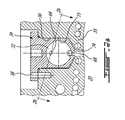
Figs. 1-2a , theengine 10 shown includes apilot subchamber 72 defined in theouter body 12, for pilot fuel injection and ignition. Thepilot subchamber 72 is provided in aninsert 34 received in a correspondinghole 36 defined through theperipheral wall 18 of theouter body 12. Theinsert 34 is retained to theperipheral wall 18 using any adequate type of connection, shown here as one or more fasteners 38 (seeFig. 2a ); other adequate types of connection include, but are not limited to, welding, brazing, retention through a cover overlapping theinsert 34 and connected to theperipheral wall 18, etc. - Referring back to
Fig. 1 , theperipheral wall 18 has a main injector elongatedhole 40 defined therethrough, in communication with therotor cavity 20 and spaced apart from theinsert 34. Amain fuel injector 42 is received and retained within this correspondinghole 40, with the tip of themain injector 42 communicating with the cavity at a point spaced apart from theinsert 34. Themain injector 42 is located rearwardly of theinsert 34 with respect to the direction R of the rotor rotation and revolution, and is angled to direct fuel forwardly into each of therotating chambers 32 sequentially with a tip hole pattern designed for an adequate spray. - The
peripheral wall 18 also has a pilot injector elongatedhole 76 defined therethrough, at an angle with respect to theinsert 34 and in communication with thesubchamber 72. Apilot fuel injector 78 is received and retained within the correspondinghole 76, with the tip of thepilot injector 78 being in communication with thesubchamber 72, for example by terminating in a corresponding opening defined in theinsert 34 between thesubchamber 72 and thepilot injector hole 76. - The
pilot injector 78 andmain injector 42 inject fuel, which in a particular embodiment is heavy fuel e.g. diesel, kerosene (jet fuel), equivalent biofuel, etc. into thechambers 32. Alternately, the fuel may be any other adequate type of fuel suitable for injection as described, including non-heavy fuel such as for example gasoline or liquid hydrogen fuel. In a particular embodiment, at least 0.5% and up to 20% of the fuel is injected through thepilot injector 78, and the remainder is injected through themain injector 42. In another particular embodiment, at most 10% of the fuel is injected through thepilot injector 78. In another particular embodiment, at most 5% of the fuel is injected through thepilot injector 78. Themain injector 42 injects the fuel such that eachrotating chamber 32 when in the combustion phase contains a lean mixture of air and fuel. - Referring to
Fig. 2a , in the embodiment shown, theinsert body 34 has theentire pilot subchamber 72 defined therein, shown here with a circular cross-section. Other geometries are also possible, including but not limited to cylindrical, conical, frustoconical, ovoid, teardrop-shaped, "light bulb"-shaped, wedge-shaped profiles, etc. Theinsert 34 includes at least oneoutlet opening 74 defined therein for communication with thecavity 20. In the embodiment shown, thesubchamber 72 has a shape forming a reduced cross-section adjacent the opening(s) 74, such that the opening(s) 74 define a restriction to the flow between thesubchamber 72 and thecavity 20. The opening(s) 74 may have various shapes and/or be defined by a pattern of multiple holes. - In the particular embodiment shown, the
insert 34 is located in theperipheral wall 18 outwardly offset from thecavity 20 such that aportion 35 of theperipheral wall 18 extends between theinsert 34 and thecavity 20. The inner end of theinsert 34 is outwardly offset from theinner surface 19 of theperipheral wall 18 defining thecavity 20, i.e. theinsert 34 is not directly exposed thecavity 20. Theportion 35 of theperipheral wall 18 extending between theinsert 34 and thecavity 20 has at least oneopening 68 defined therethrough extending from theinner surface 19 to theinsert hole 36, and in communication with the outlet opening(s) 74. In one embodiment, an air gap is provided between the inner end of theinsert 34 and the adjacent portion of theperipheral wall 18. Cooling channels may be provided in the portion of theperipheral wall 18 which extends between theinsert 34 and thecavity 20. - Alternately, the insert may have inner surface which is continuous with the
inner surface 19 of theperipheral wall 20 to define thecavity 20, with the outlet opening(s) directly opening to thecavity 20. - The volume of the
subchamber 72 is selected to obtain a stoichiometric mixture around ignition within an acceptable delay, with some of the exhaust product from the previous combustion cycle remaining in thesubchamber 72. In a particular embodiment, the volume of thesubchamber 72 is at least 0.5% and up to 3.5% of the displacement volume, with the displacement volume being defined as the difference between the maximum and minimum volumes of onechamber 32. In another particular embodiment, the volume of thesubchamber 72 corresponds to from about 0.625% to about 1.25% of the displacement volume. - The volume of the
subchamber 72 may also be defined as a portion of the combustion volume, which is the sum of the minimum chamber volume Vmin (including the recess) and the volume of the subchamber V2 itself. In a particular embodiment thesubchamber 72 has a volume corresponding to from 5% to 25% of the combustion volume, i.e. V2 = 5% to 25% of (V2 + Vmin). In another particular embodiment, thesubchamber 72 has a volume corresponding to from 10% to 12% of the combustion volume, i.e. V2 = 10% to 12% of (V2 + Vmin). - It is understood that the
particular engine 10 and insert 34 configurations shown and described are provided as an example only and that other configurations are possible. - Referring to
Figs. 2a ,2b and 2c , ignition is provided by one or more ignition elements 84 (two in the embodiment shown). In a particular embodiment, theignition element 84 is a heating element. Eachelement 84 extends into an element cavity 88 (seeFigs. 2b-2c ) which is defined through theinsert 34 adjacent thesubchamber 72. Aportion 86 of theelement 84 is in communication with thesubchamber 72 through acommunication opening 64 defined in theinsert 34 between theelement cavity 88 and thesubchamber 72. In the embodiment shown, theportion 86 of theelement 84 includes its tip. - It can be seen that the
communication opening 64 has a cross-section which is smaller than the corresponding cross-section of the exposedportion 86. In other words, thecommunication opening 64 is smaller than the correspondingportion 86 of theelement 84 which is adjacent to it, such as to prevent theportion 86 of theelement 84 from passing completely therethrough. - It is understood that the
opening 64 may have a dimension in one direction which is larger than the corresponding dimension of the exposedportion 86 of theelement 84, as long as the overall shape and dimensions of theopening 64 do not allow theportion 86 of theelement 84 to completely pass through theopening 64. In a particular embodiment, this allows for theportion 86 of theelement 84 to remain outside of thesubchamber 72 if it breaks off from the remainder of theelement 84. - In a particular embodiment, the
element 84 is a heating element also in heat transfer communication with thesubchamber wall 73. Thesubchamber wall 73 may thus be sufficiently heated to act as an ignition element for the fuel of thesubchamber 72, in addition to or instead of the direct ignition by theelement 84. - In a particular embodiment, the
element 84 is a glow plug. - Referring to
Figs. 3a-3b , in another embodiment, theinsert 34 includes one or more elongated ignition or heating elements 184 (one in the embodiment shown), which may be for example glow plugs and which extend partially within thesubchamber 72. A major portion of theelement 184, including its tip, remains outside of thesubchamber 72. In the embodiment shown, theelement 184 extends parallel or substantially parallel to a longitudinal axis L of theinsert 34. It is understood that in another embodiment, theelement 184 may have a different orientation. - In the embodiment shown, the exposed
portion 186 is cylindrical and a circumferential part thereof extends within thesubchamber 72 through thecommunication opening 164, with the circumferential part extending along an arc defining an angle α of less than 180 degrees, i.e. the central longitudinal axis of thecylindrical portion 186 remains out of thesubchamber 72. As such, the exposedportion 186 is prevented from completely passing through thecommunication opening 164, the dimension of the opening defined transversely to the longitudinal axis L being smaller than the diameter of the exposedportion 186. - The
element 184 may also be a heating element in heat transfer communication with thesubchamber wall 73 to allow thesubchamber wall 73 to be sufficiently heated to act as an ignition element for the fuel of thesubchamber 72. - Referring to
Figs. 4a-4b , in another embodiment, theinsert 34 includes one or more elongated ignition elements 284 (one in the embodiment shown) which are heating elements, and which may be for example glow plugs. Thewall 73 of thesubchamber 72 forms anindent 79 protruding within thesubchamber 72, and theelement 284 extends completely outside of thesubchamber 72 against this indent. Thewall 73 of thesubchamber 72 thus curves around theelement 284, allowing theelement 284 to be positioned closer to a center of thesubchamber 72 while remaining outside thereof. In the embodiment shown, theelement 284 extends parallel or substantially parallel to the longitudinal axis L of theinsert 34. It is understood that in another embodiment, theelement 284 may have a different orientation. Theelement 284 is in heat transfer communication with thesubchamber wall 73 to allow thesubchamber wall 73 to be sufficiently heated to act as an ignition element for the fuel of thesubchamber 72. - Although not shown, an opening small enough to prevent the adjacent portion of the
element 284 from completely passing therethrough may be provided through theindent 79 to form a communication between theelement 284 and thesubchamber 72. - Referring to
Fig. 5 , in another embodiment, theinsert 34 includes one or more elongated ignition elements 384 (two in the embodiment shown) in the form of heating elements. In a particular embodiment, eachheating element 384 is a glow plug, with a heatable portion thereof being located at its tip. Alternately, eachheating element 384 may be heatable along a greater portion of its length, for example the portion thereof in proximity of thesubchamber 72. Theelements 184 extend through theinsert 34 completely outside of thesubchamber 72 but in proximity therewith such that heating of theelements 384 heats thewall 73 of thesubchamber 72. In the embodiment shown, theelements 384 extend parallel or substantially parallel to the longitudinal axis L of theinsert 34. It is understood that in another embodiment, theelement 384 may have a different orientation. - Although not shown, an opening small enough to prevent the adjacent portion of the
element 384 from completely passing therethrough may be provided through theinsert 34 to form a communication between theelement 384 and thesubchamber 72. - Referring to
Fig. 6 , in another embodiment, theignition element 484 is provided as a coiled heating element extending around thesubchamber 72. In the embodiment shown, theelement 484 extends parallel or substantially parallel to the longitudinal axis L of theinsert 34, and then curves to circle thesubchamber 72 following a helical pattern. It is understood that in another embodiment, theelement 484 may have a different orientation. Thecoiled element 484 may be for example an electrical element, including a heatable wire received in a ceramic outer layer. In the embodiment shown, thecoiled element 484 is located completely outside of the subchamber but in proximity therewith such that heating of theelement 484 heats thesubchamber wall 73. - Although not shown, one or more openings small enough to prevent the adjacent portion of the
element 484 from completely passing therethrough may be provided through theinsert 34 to form a communication between theelement 484 and thesubchamber 72. Theelement 484 may partially protrude into thesubchamber 72 through this opening. - In a particular embodiment, each
element subchamber wall 73 than to the outer wall of theinsert 34 to maximise heat transfer to thesubchamber 72 and minimize heat transfer to theperipheral wall 18. - In a particular embodiment, the
insert 34 is made of a material having a greater high temperature properties and/or lower thermal conductivity than that of theperipheral wall 18, which may be for example made of aluminum. In a particular embodiment, the material of theinsert 34 has limited thermal conductivity allowing retention of the heat provided by theelement element insert 34 is made of a nickel or cobalt based super alloy. Alternate materials can be used, including but not limited to appropriate types of ceramics. - In another embodiment, both the
insert 34 and theperipheral wall 18 are made of a same material having sufficient heat resistance and adequate high temperature properties to resist the high temperatures within thesubchamber 72. In the embodiments where thesubchamber wall 73 is used as an ignition element, the material of theinsert 34 has appropriate thermal conductivity to allow for thesubchamber wall 73 to act as an ignition element. - In a particular embodiment, the
elements subchamber 72 may allow for an improved life of the element by reducing exposition thereof to the combustion process within the subchamber, when compared to the use of a glow plug with its tip completely received within the subchamber. - The teachings herein are applicable to many rotary engine types, and not just Wankel engines. In a particular embodiment, the rotary engine may be a single or eccentric type rotary engine in which the rotor rotates about a fixed center of rotation. For example, the rotary engine may be a sliding vane engine, such as described in
US patent No. 5,524,587 issued June 11, 1996 or inUS patent No. 5,522,356 issued June 4, 1996 . In another particular embodiment, the rotary engine may be an oscillatory rotating engine, including two or more rotors rotating at different angular velocities, causing the distance between portions of the rotors to vary and as such the chamber volume to change. In another particular embodiment, the rotary engine may be a planetary rotating engine having a different geometry than that of the Wankel engine, such as for example a planetary engine having a rotor cavity with an epitrochoid profile defining three lobes and a rotor with four apex portions. Examples of such non-Wankel rotary engines are shown in Applicant'sU.S. application No. 14/796,185 filed January 25, 2013 - The above description is meant to be exemplary only, and one skilled in the art will recognize that changes may be made to the embodiments described without departing from the scope of the invention(s) disclosed. For example, the mechanical arrangements of the rotary engines described above are merely examples of many possible configurations which are suitable for use with the present invention(s). Any suitable injector configuration and arrangement may be used. Any suitable ignition element configuration and type may be used. Hence, modifications which fall within the scope of the present invention will be apparent to those skilled in the art, in light of a review of this disclosure, and such modifications are intended to fall within the appended claims.
Claims (14)
- An outer body (12) for a rotary engine (10) comprising:two axially spaced apart end walls (14);a peripheral wall (18) extending between the end walls (14) and defining an internal cavity (20) therewith for receiving a rotor (24) therein;an insert (34) in the peripheral wall (18) of the outer body (12), the insert (34) having a subchamber (72) defined therein in communication with the cavity (20);the outer body (20) further having:a pilot injector hole (76) defined therethrough in communication with the subchamber (72) and sized to receive a pilot fuel injector (78), anda main fuel injector hole (40) defined therethrough in communication with the cavity (20), spaced apart from the insert (34) and sized to receive a main fuel injector (42); andan ignition element (84;184;284;384;484) received in the insert in communication with the subchamber (72) through an opening (64;164) smaller than corresponding dimensions of a portion (86;186) of the element (84;184;284;384;484) extending adjacent the opening (64;164) such as to prevent the portion (86; 186) from completely passing through the opening (64; 164).
- The outer body as defined in claim 1, wherein the portion of the element (84) includes a tip (86) thereof partly received through the opening.
- The outer body as defined in claim 1, wherein the portion (186) of the element is cylindrical and a circumferential part thereof extends within the subchamber (72) through the communication opening (164), a central longitudinal axis of the cylindrical element (84) extending out of the pilot subchamber (72).
- The outer body as defined in claim 1, wherein the element is elongated and extends within the insert (34) without protruding into the subchamber (72).
- The outer body as defined in any one of claims 1 to 4, wherein the insert (34) is made of a material having one or both of greater high temperature properties and lower thermal conductivity than that of the peripheral wall (18).
- The outer body as defined in any one of claims 1 to 5, wherein the ignition element (78) is a heating element and the portion of the element (84;184;284;384;484) is heatable.
- The outer body as defined in any one of claims 1 to 6, wherein the subchamber (72) has a shape forming a reduced cross-section adjacent the communication thereof with the internal cavity (20).
- The outer body as defined in any one of claims 1 to 7, wherein the ignition element extends into an element cavity (88) defined through the insert (34) adjacent the subchamber (72), a portion of the element being in communication with the subchamber (72) through a communication opening defined in the insert (34) between the element cavity (88) and the subchamber (72), the communication opening having a cross-section smaller than a corresponding cross-section of the portion of the element (84;184;284;384;484).
- A rotary engine including an outer body (12) as defined in any one of claims 1 to 8 and a rotor body (24) rotatable within the internal cavity (20) in sealing engagement with the walls (14,18) of the outer body (12) and defining at least one chamber (32) of variable volume in the internal cavity (20) around the rotor body (24), wherein the rotor body (12) defines three apex portions (30) and is engaged to an eccentric portion of a shaft to rotate and perform orbital revolutions within the internal cavity (20), the internal cavity (20) having an epichotroid shape defining two lobes.
- A method of combusting fuel in a rotary engine (10) having a rotor (24) rotating in a cavity (20), the method comprising:injecting a minor portion of the fuel into a subchamber (72) defined in an insert (34) located in a peripheral wall (18) of the engine (10);activating a portion of an ignition element (84;184;284;384;484) received in the insert (34) adjacent the subchamber (72);exposing the portion of the element to the fuel in the subchamber through a communication opening (64;164) defined through the insert (34), the communication opening (64;164) being sized to prevent the portion of the element (84;184;284;384;484) from completely passing therethrough;igniting the fuel in the subchamber (72) with the portion of the element (84;184;284;384;484);circulating the ignited fuel from the subchamber (72) to the cavity (20); andinjecting a remainder of the fuel into the cavity (20) independently of and spaced apart from the subchamber (72).
- The method as defined in claim 10, wherein the ignition element (284;384;484) is a heating element, the method further including heating a wall (73) of the subchamber (72) with the portion of the element (284;384;484), and igniting the fuel in the subchamber (72) with the heated wall (73).
- The method as defined in claim 10 or 11, wherein the fuel is heavy fuel.
- The method as defined in any one of claims 10 to 12, wherein exposing the portion of the element (284;384;484) to the fuel in the subchamber (72) is performed with the portion of the element being located completely outside of the subchamber (72).
- The method as defined in any one of claims 10 to 12, wherein exposing the portion (86; 186) of the element (84; 184) to the fuel in the subchamber (72) is performed with the portion (86; 186) of the element (84; 184) protruding partially in the subchamber (72) through the communication opening (64; 164).
Applications Claiming Priority (1)
| Application Number | Priority Date | Filing Date | Title |
|---|---|---|---|
| US13/910,807 US9334794B2 (en) | 2013-06-05 | 2013-06-05 | Rotary internal combustion engine with pilot subchamber and ignition element |
Publications (2)
| Publication Number | Publication Date |
|---|---|
| EP2811135A1 true EP2811135A1 (en) | 2014-12-10 |
| EP2811135B1 EP2811135B1 (en) | 2016-08-03 |
Family
ID=50932973
Family Applications (1)
| Application Number | Title | Priority Date | Filing Date |
|---|---|---|---|
| EP14171171.3A Active EP2811135B1 (en) | 2013-06-05 | 2014-06-04 | Rotary internal combustion engine with pilot subchamber and ignition element |
Country Status (5)
| Country | Link |
|---|---|
| US (4) | US9334794B2 (en) |
| EP (1) | EP2811135B1 (en) |
| CA (1) | CA2851077C (en) |
| ES (1) | ES2588076T3 (en) |
| PL (1) | PL2811135T3 (en) |
Families Citing this family (18)
| Publication number | Priority date | Publication date | Assignee | Title |
|---|---|---|---|---|
| US9528434B1 (en) * | 2011-07-28 | 2016-12-27 | Pratt & Whitney Canada Corp. | Rotary internal combustion engine with pilot subchamber |
| US10544732B2 (en) | 2011-07-28 | 2020-01-28 | Pratt & Whitney Canada Corp. | Rotary internal combustion engine with removable subchamber insert |
| US10557407B2 (en) * | 2011-07-28 | 2020-02-11 | Pratt & Whitney Canada Corp. | Rotary internal combustion engine with pilot subchamber |
| US9038594B2 (en) | 2011-07-28 | 2015-05-26 | Pratt & Whitney Canada Corp. | Rotary internal combustion engine with pilot subchamber |
| US9121277B2 (en) * | 2012-02-06 | 2015-09-01 | Pratt & Whitney Canada Corp. | Rotary internal combustion engine with cooled insert |
| US9334794B2 (en) * | 2013-06-05 | 2016-05-10 | Pratt & Whitney Canada Corp. | Rotary internal combustion engine with pilot subchamber and ignition element |
| CN106796031B (en) | 2014-08-18 | 2022-07-08 | 伍德沃德有限公司 | Torch type igniter |
| US10041402B2 (en) | 2016-05-12 | 2018-08-07 | Pratt & Whitney Canada Corp. | Internal combustion engine with split pilot injection |
| CN107013321A (en) * | 2017-05-18 | 2017-08-04 | 江苏大学 | A kind of passage of igniting of rotary engine |
| US10544771B2 (en) * | 2017-06-14 | 2020-01-28 | Caterpillar Inc. | Fuel injector body with counterbore insert |
| US10145291B1 (en) | 2017-10-10 | 2018-12-04 | Pratt & Whitney Canada Corp. | Rotary engine and method of combusting fuel |
| US10801394B2 (en) | 2017-11-29 | 2020-10-13 | Pratt & Whitney Canada Corp. | Rotary engine with pilot subchambers |
| US11421601B2 (en) | 2019-03-28 | 2022-08-23 | Woodward, Inc. | Second stage combustion for igniter |
| BR102019027843A2 (en) * | 2019-12-26 | 2021-07-06 | Robert Bosch Limitada | system and method of managing the temperature of fuel injected in internal combustion engines |
| BR102019027845A2 (en) | 2019-12-26 | 2021-07-06 | Robert Bosch Limitada | system and method of managing the temperature of fuel injected in internal combustion engines |
| US11506116B2 (en) | 2020-11-04 | 2022-11-22 | William Todd Hodges | Rotary combustion engine with integrated multistage fuel system |
| US11619165B1 (en) | 2020-11-04 | 2023-04-04 | William Todd Hodges | Rotary combustion engine with integrated multistage fuel system |
| US11905836B1 (en) * | 2023-06-08 | 2024-02-20 | Pratt & Whitney Canada Corp. | Rotary engine with single dual-fuel injector |
Citations (10)
| Publication number | Priority date | Publication date | Assignee | Title |
|---|---|---|---|---|
| DE1926474A1 (en) * | 1968-05-23 | 1970-01-29 | Dynatech Corp | Internal combustion engine |
| US3987759A (en) * | 1975-06-03 | 1976-10-26 | Curtiss-Wright Corporation | Stratified charge rotary engine with variable spray angle fuel nozzle |
| US4091789A (en) * | 1977-02-11 | 1978-05-30 | Curtiss-Wright Corporation | Stratified charge fuel injection system for rotary engine |
| US5522356A (en) | 1992-09-04 | 1996-06-04 | Spread Spectrum | Method and apparatus for transferring heat energy from engine housing to expansion fluid employed in continuous combustion, pinned vane type, integrated rotary compressor-expander engine system |
| US5524587A (en) | 1995-03-03 | 1996-06-11 | Mallen Research Ltd. Partnership | Sliding vane engine |
| WO1998057037A1 (en) * | 1997-06-09 | 1998-12-17 | Pats, Inc. | Prechamber combustion and method for a rotary diesel engine |
| US7753036B2 (en) | 2007-07-02 | 2010-07-13 | United Technologies Corporation | Compound cycle rotary engine |
| US7775044B2 (en) | 2003-02-24 | 2010-08-17 | Pratt & Whitney Canada Corp. | Low volumetric compression ratio integrated turbo-compound rotary engine |
| WO2011092365A1 (en) * | 2010-02-01 | 2011-08-04 | Diaz Escano Jesus Manuel | Rotary engine working with alternative fuels |
| EP2551448A2 (en) * | 2011-07-28 | 2013-01-30 | Pratt & Whitney Canada Corp. | Rotary internal combustion engine with pilot subchamber and method of injecting fuel |
Family Cites Families (65)
| Publication number | Priority date | Publication date | Assignee | Title |
|---|---|---|---|---|
| US1539133A (en) * | 1920-08-13 | 1925-05-26 | Harry Newton Hocken | Spark-plug attachment |
| GB780023A (en) | 1954-05-25 | 1957-07-31 | Walter Pflaum | New or improved combustion process for internal combustion engines with subdivided combustion space |
| US2935054A (en) * | 1957-03-08 | 1960-05-03 | Kloeckner Humboldt Deutz Ag | Fuel injection internal combustion engine |
| US2932289A (en) * | 1958-10-20 | 1960-04-12 | Julius E Witzky | Precombustion chamber |
| US3058452A (en) * | 1959-03-14 | 1962-10-16 | Motoren Werke Mannheim Ag | Internal combustion engines |
| US3140697A (en) * | 1959-12-28 | 1964-07-14 | Renault | Compression ignition engines |
| US3102521A (en) * | 1960-12-20 | 1963-09-03 | Fmc Corp | Combustion apparatus for an internal combustion engine |
| US3958538A (en) * | 1972-05-15 | 1976-05-25 | Nissan Motor Co., Ltd. | Gaseous ignition system for internal combustion engine |
| AT331569B (en) * | 1972-05-25 | 1976-08-25 | List Hans | COMBUSTION ENGINE WITH FUEL INJECTION |
| GB1437528A (en) * | 1973-10-09 | 1976-05-26 | Rolls Royce Motors Ltd | Combustion chamber arrangement for rotary compression-ignition engines |
| US3894518A (en) * | 1973-12-12 | 1975-07-15 | Curtiss Wright Corp | Stratified charge rotary engine with dual fuel injection |
| JPS5216765B2 (en) * | 1974-01-25 | 1977-05-11 | ||
| US4009688A (en) * | 1974-03-04 | 1977-03-01 | Toyo Kogyo Co., Ltd. | Rotary piston type engine |
| US4108133A (en) * | 1974-07-31 | 1978-08-22 | Toyota Jidosha Kogyo Kabushiki Kaisha | Internal combustion engine having an auxiliary combustion chamber without an intake valve |
| US3960115A (en) * | 1974-10-04 | 1976-06-01 | Curtiss-Wright Corporation | Stratified charge rotary engine (method of operation) |
| US3957021A (en) | 1974-10-15 | 1976-05-18 | Curtiss-Wright Corporation | Precombustion chamber rotary piston diesel engine |
| US3977367A (en) * | 1974-10-21 | 1976-08-31 | Curtiss-Wright Corporation | Dual fuel injection nozzle |
| DE2510176B1 (en) * | 1975-03-08 | 1976-08-26 | Daimler Benz Ag | FOUR-STROKE PISTON ENGINE WITH IGNITION CHAMBER |
| US3987763A (en) * | 1975-04-21 | 1976-10-26 | General Motors Corporation | Rotary engine combustion arrangement |
| US4037412A (en) * | 1975-10-09 | 1977-07-26 | Curtiss-Wright Corporation | Compound spark-ignition and diesel engine |
| DE2549933A1 (en) * | 1975-11-07 | 1977-05-12 | Porsche Ag | ANTI-CHAMBER IN THE CYLINDER HEAD OF AN EXTERNAL-STARTED COMBUSTION MACHINE |
| US4060058A (en) * | 1975-11-28 | 1977-11-29 | Ford Motor Company | Internal combustion engine control system |
| US4029058A (en) * | 1976-03-15 | 1977-06-14 | Curtiss-Wright Corporation | Stratified charge rotary engine with side housing fuel injection |
| JPS52129806A (en) * | 1976-04-22 | 1977-10-31 | Nippon Soken Inc | Combustion chamber of internal combustion engine |
| US4066044A (en) * | 1976-09-09 | 1978-01-03 | Curtiss-Wright Corporation | Rotary engine with tongue and groove inserts in rotor faces |
| US4080934A (en) * | 1976-09-09 | 1978-03-28 | Curtiss-Wright Corporation | Rotary engine with inserts in rotor faces |
| US4124000A (en) * | 1976-11-03 | 1978-11-07 | General Motors Corporation | Mixed cycle stratified charge engine with ignition antechamber |
| JPS5813071Y2 (en) * | 1976-11-26 | 1983-03-14 | トヨタ自動車株式会社 | Pre-chamber structure of internal combustion engine with large pre-chamber |
| US4083329A (en) * | 1977-02-14 | 1978-04-11 | Curtiss-Wright Corporation | Rotary engine with a pilot fuel nozzle downstream of top center |
| JPS53138006U (en) * | 1977-04-06 | 1978-11-01 | ||
| JPS5497504U (en) * | 1977-12-20 | 1979-07-10 | ||
| US4300497A (en) * | 1980-06-30 | 1981-11-17 | Rockwell International Corporation | Prevaporizing diesel precombustion chamber |
| US4406260A (en) * | 1982-02-08 | 1983-09-27 | General Motors Corporation | Valved prechamber diesel engine and methods of operating |
| DE3519835A1 (en) * | 1984-06-07 | 1985-12-12 | Nissan Motor Co., Ltd., Yokohama, Kanagawa | COMBUSTION ENGINE |
| DE3520775A1 (en) * | 1984-06-12 | 1985-12-12 | Nissan Motor Co., Ltd., Yokohama, Kanagawa | Diesel engine with a swirl chamber and a flame distribution recess molded into the piston crown |
| JPS61171821A (en) * | 1985-01-25 | 1986-08-02 | Nissan Motor Co Ltd | Diesel engine with swirl chamber |
| US4759325A (en) * | 1987-01-28 | 1988-07-26 | Deere & Company | Rotary engine cooling system |
| US5022366A (en) * | 1989-09-18 | 1991-06-11 | John Deere Technologies International, Inc. | Rotary engine with dual spark plugs and fuel injectors |
| US5024193A (en) * | 1990-02-06 | 1991-06-18 | Caterpillar Inc. | Fuel combustion system, method, and nozzle member therefor |
| US5163385A (en) * | 1992-03-12 | 1992-11-17 | The United States Of America As Represented By The United States Department Of Energy | Coal-water slurry fuel internal combustion engine and method for operating same |
| US5721788A (en) | 1992-07-31 | 1998-02-24 | Corbis Corporation | Method and system for digital image signatures |
| DE4238922C2 (en) | 1992-11-19 | 1996-08-08 | Gutehoffnungshuette Man | Method and device for tensioning and releasing tie rods in multi-part gas turbine rotors |
| JP3406119B2 (en) * | 1995-06-05 | 2003-05-12 | ヤマハ発動機株式会社 | 2-stroke diesel engine with swirl chamber auxiliary combustion chamber |
| US5533476A (en) * | 1995-06-14 | 1996-07-09 | Dresser-Rand Company | Walled precombustion chamber unit |
| US5662082A (en) * | 1995-12-05 | 1997-09-02 | Compressor Engineering Corporation | Pre-combustion chamber for internal combustion engine and method of manufacture thereof |
| US5678517A (en) * | 1996-08-09 | 1997-10-21 | Thermo Power Corporation | Internal combustion reciprocating engine and method for burning a mixture of fuel and air therein |
| US5836282A (en) | 1996-12-27 | 1998-11-17 | Samsung Electronics Co., Ltd. | Method of reducing pollution emissions in a two-stroke sliding vane internal combustion engine |
| US5915351A (en) * | 1997-02-24 | 1999-06-29 | Chrysler Corporation | Insulated precombustion chamber |
| CN1292153C (en) * | 1998-02-23 | 2006-12-27 | 卡明斯发动机公司 | Premixed charge compression ignition engine with optimal combustion control |
| US5947076A (en) * | 1998-04-17 | 1999-09-07 | Caterpillar Inc. | Fuel combustion assembly for an internal combustion engine having an encapsulated spark plug for igniting lean gaseous fuel within a precombustion chamber |
| US6016785A (en) * | 1998-10-01 | 2000-01-25 | Caterpillar Inc. | Pre-combustion chamber assembly and method |
| US6162034A (en) | 1999-03-01 | 2000-12-19 | Mallen Research Ltd., Partnership | Vane pumping machine utilizing invar-class alloys for maximizing operating performance and reducing pollution emissions |
| US6244240B1 (en) | 1999-04-30 | 2001-06-12 | Mallen Research Limited Partnership | Rotary positive-displacement scavenging device for rotary vane pumping machine |
| US6321713B1 (en) | 2000-08-02 | 2001-11-27 | Mallen Research Corporation | Hot wall combustion insert for a rotary vane pumping machine |
| US6513483B2 (en) * | 2001-02-07 | 2003-02-04 | Cooper Cameron Corporation | Pre-combustion chamber for an internal combustion engine |
| EP1403482B1 (en) * | 2002-09-27 | 2010-04-21 | Kubota Corporation | Swirl chamber used in association with a combustion chamber for diesel engines |
| US7147436B2 (en) | 2004-04-15 | 2006-12-12 | United Technologies Corporation | Turbine engine rotor retainer |
| DE102004023409B4 (en) * | 2004-05-12 | 2007-05-16 | Gottfried Schubert | High-compression gasoline engine with throttle control, spark ignition and direct fuel injection into a pre-combustion chamber |
| US9010293B2 (en) | 2006-04-07 | 2015-04-21 | David A. Blank | Combustion control via homogeneous combustion radical ignition (HCRI) or partial HCRI in cyclic IC engines |
| DE102007015036B4 (en) | 2007-03-29 | 2008-11-20 | Multitorch Gmbh | Laser ignition for gas mixtures |
| WO2009114264A1 (en) * | 2008-03-12 | 2009-09-17 | Cameron International Corporation | Pre-chamber |
| US8276466B2 (en) | 2010-03-31 | 2012-10-02 | Kulite Semiconductor Products, Inc. | Two or three-axis shear load cell |
| US8794923B2 (en) | 2010-10-29 | 2014-08-05 | United Technologies Corporation | Gas turbine engine rotor tie shaft arrangement |
| US9664047B2 (en) | 2012-08-23 | 2017-05-30 | Mallen Research Limited Partnership | Positive displacement rotary devices with uniquely configured voids |
| US9334794B2 (en) * | 2013-06-05 | 2016-05-10 | Pratt & Whitney Canada Corp. | Rotary internal combustion engine with pilot subchamber and ignition element |
-
2013
- 2013-06-05 US US13/910,807 patent/US9334794B2/en active Active
-
2014
- 2014-05-02 CA CA2851077A patent/CA2851077C/en active Active
- 2014-06-04 ES ES14171171.3T patent/ES2588076T3/en active Active
- 2014-06-04 EP EP14171171.3A patent/EP2811135B1/en active Active
- 2014-06-04 PL PL14171171.3T patent/PL2811135T3/en unknown
-
2016
- 2016-05-02 US US15/143,974 patent/US10006359B2/en active Active
-
2018
- 2018-03-20 US US15/926,568 patent/US10458325B2/en active Active
-
2019
- 2019-09-18 US US16/574,650 patent/US10968820B2/en active Active
Patent Citations (10)
| Publication number | Priority date | Publication date | Assignee | Title |
|---|---|---|---|---|
| DE1926474A1 (en) * | 1968-05-23 | 1970-01-29 | Dynatech Corp | Internal combustion engine |
| US3987759A (en) * | 1975-06-03 | 1976-10-26 | Curtiss-Wright Corporation | Stratified charge rotary engine with variable spray angle fuel nozzle |
| US4091789A (en) * | 1977-02-11 | 1978-05-30 | Curtiss-Wright Corporation | Stratified charge fuel injection system for rotary engine |
| US5522356A (en) | 1992-09-04 | 1996-06-04 | Spread Spectrum | Method and apparatus for transferring heat energy from engine housing to expansion fluid employed in continuous combustion, pinned vane type, integrated rotary compressor-expander engine system |
| US5524587A (en) | 1995-03-03 | 1996-06-11 | Mallen Research Ltd. Partnership | Sliding vane engine |
| WO1998057037A1 (en) * | 1997-06-09 | 1998-12-17 | Pats, Inc. | Prechamber combustion and method for a rotary diesel engine |
| US7775044B2 (en) | 2003-02-24 | 2010-08-17 | Pratt & Whitney Canada Corp. | Low volumetric compression ratio integrated turbo-compound rotary engine |
| US7753036B2 (en) | 2007-07-02 | 2010-07-13 | United Technologies Corporation | Compound cycle rotary engine |
| WO2011092365A1 (en) * | 2010-02-01 | 2011-08-04 | Diaz Escano Jesus Manuel | Rotary engine working with alternative fuels |
| EP2551448A2 (en) * | 2011-07-28 | 2013-01-30 | Pratt & Whitney Canada Corp. | Rotary internal combustion engine with pilot subchamber and method of injecting fuel |
Also Published As
| Publication number | Publication date |
|---|---|
| US20200011234A1 (en) | 2020-01-09 |
| US20160245165A1 (en) | 2016-08-25 |
| US9334794B2 (en) | 2016-05-10 |
| US10968820B2 (en) | 2021-04-06 |
| CA2851077A1 (en) | 2014-12-05 |
| PL2811135T3 (en) | 2016-12-30 |
| US10458325B2 (en) | 2019-10-29 |
| US10006359B2 (en) | 2018-06-26 |
| US20140360456A1 (en) | 2014-12-11 |
| EP2811135B1 (en) | 2016-08-03 |
| CA2851077C (en) | 2023-08-01 |
| US20180209332A1 (en) | 2018-07-26 |
| ES2588076T3 (en) | 2016-10-28 |
Similar Documents
| Publication | Publication Date | Title |
|---|---|---|
| US10968820B2 (en) | Method of combusting fuel in a rotary internal combustion engine with pilot subchamber and ignition element | |
| US9957885B2 (en) | Internal combustion engine with common rail pilot and main injection | |
| CA2844015C (en) | Rotary internal combustion engine with pilot subchamber | |
| US10006358B2 (en) | Rotary internal combustion engine with pilot subchamber | |
| US9708966B2 (en) | Internal combustion engine with pilot and main injection | |
| EP2551448B1 (en) | Rotary internal combustion engine with pilot subchamber and method of injecting fuel | |
| EP3299607B1 (en) | Method of operating an engine having a pilot subchamber at partial load conditions |
Legal Events
| Date | Code | Title | Description |
|---|---|---|---|
| PUAI | Public reference made under article 153(3) epc to a published international application that has entered the european phase |
Free format text: ORIGINAL CODE: 0009012 |
|
| 17P | Request for examination filed |
Effective date: 20140604 |
|
| AK | Designated contracting states |
Kind code of ref document: A1 Designated state(s): AL AT BE BG CH CY CZ DE DK EE ES FI FR GB GR HR HU IE IS IT LI LT LU LV MC MK MT NL NO PL PT RO RS SE SI SK SM TR |
|
| AX | Request for extension of the european patent |
Extension state: BA ME |
|
| R17P | Request for examination filed (corrected) |
Effective date: 20150610 |
|
| RBV | Designated contracting states (corrected) |
Designated state(s): AL AT BE BG CH CY CZ DE DK EE ES FI FR GB GR HR HU IE IS IT LI LT LU LV MC MK MT NL NO PL PT RO RS SE SI SK SM TR |
|
| GRAP | Despatch of communication of intention to grant a patent |
Free format text: ORIGINAL CODE: EPIDOSNIGR1 |
|
| RIC1 | Information provided on ipc code assigned before grant |
Ipc: F02B 53/10 20060101ALN20160113BHEP Ipc: F02B 53/12 20060101ALI20160113BHEP Ipc: F02B 19/10 20060101AFI20160113BHEP Ipc: F02B 53/00 20060101ALN20160113BHEP Ipc: F02B 55/14 20060101ALN20160113BHEP Ipc: F01C 1/22 20060101ALN20160113BHEP |
|
| INTG | Intention to grant announced |
Effective date: 20160209 |
|
| GRAS | Grant fee paid |
Free format text: ORIGINAL CODE: EPIDOSNIGR3 |
|
| GRAA | (expected) grant |
Free format text: ORIGINAL CODE: 0009210 |
|
| RIN1 | Information on inventor provided before grant (corrected) |
Inventor name: GAUL, MICHAEL Inventor name: VILLENEUVE, BRUNO Inventor name: JULIEN, ANDRE |
|
| AK | Designated contracting states |
Kind code of ref document: B1 Designated state(s): AL AT BE BG CH CY CZ DE DK EE ES FI FR GB GR HR HU IE IS IT LI LT LU LV MC MK MT NL NO PL PT RO RS SE SI SK SM TR |
|
| REG | Reference to a national code |
Ref country code: GB Ref legal event code: FG4D |
|
| REG | Reference to a national code |
Ref country code: CH Ref legal event code: EP Ref country code: AT Ref legal event code: REF Ref document number: 817488 Country of ref document: AT Kind code of ref document: T Effective date: 20160815 |
|
| REG | Reference to a national code |
Ref country code: IE Ref legal event code: FG4D |
|
| REG | Reference to a national code |
Ref country code: DE Ref legal event code: R096 Ref document number: 602014002949 Country of ref document: DE |
|
| REG | Reference to a national code |
Ref country code: ES Ref legal event code: FG2A Ref document number: 2588076 Country of ref document: ES Kind code of ref document: T3 Effective date: 20161028 |
|
| REG | Reference to a national code |
Ref country code: NL Ref legal event code: MP Effective date: 20160803 |
|
| REG | Reference to a national code |
Ref country code: LT Ref legal event code: MG4D |
|
| PG25 | Lapsed in a contracting state [announced via postgrant information from national office to epo] |
Ref country code: NO Free format text: LAPSE BECAUSE OF FAILURE TO SUBMIT A TRANSLATION OF THE DESCRIPTION OR TO PAY THE FEE WITHIN THE PRESCRIBED TIME-LIMIT Effective date: 20161103 Ref country code: FI Free format text: LAPSE BECAUSE OF FAILURE TO SUBMIT A TRANSLATION OF THE DESCRIPTION OR TO PAY THE FEE WITHIN THE PRESCRIBED TIME-LIMIT Effective date: 20160803 Ref country code: NL Free format text: LAPSE BECAUSE OF FAILURE TO SUBMIT A TRANSLATION OF THE DESCRIPTION OR TO PAY THE FEE WITHIN THE PRESCRIBED TIME-LIMIT Effective date: 20160803 Ref country code: IS Free format text: LAPSE BECAUSE OF FAILURE TO SUBMIT A TRANSLATION OF THE DESCRIPTION OR TO PAY THE FEE WITHIN THE PRESCRIBED TIME-LIMIT Effective date: 20161203 Ref country code: HR Free format text: LAPSE BECAUSE OF FAILURE TO SUBMIT A TRANSLATION OF THE DESCRIPTION OR TO PAY THE FEE WITHIN THE PRESCRIBED TIME-LIMIT Effective date: 20160803 Ref country code: LT Free format text: LAPSE BECAUSE OF FAILURE TO SUBMIT A TRANSLATION OF THE DESCRIPTION OR TO PAY THE FEE WITHIN THE PRESCRIBED TIME-LIMIT Effective date: 20160803 Ref country code: RS Free format text: LAPSE BECAUSE OF FAILURE TO SUBMIT A TRANSLATION OF THE DESCRIPTION OR TO PAY THE FEE WITHIN THE PRESCRIBED TIME-LIMIT Effective date: 20160803 |
|
| PG25 | Lapsed in a contracting state [announced via postgrant information from national office to epo] |
Ref country code: GR Free format text: LAPSE BECAUSE OF FAILURE TO SUBMIT A TRANSLATION OF THE DESCRIPTION OR TO PAY THE FEE WITHIN THE PRESCRIBED TIME-LIMIT Effective date: 20161104 Ref country code: LV Free format text: LAPSE BECAUSE OF FAILURE TO SUBMIT A TRANSLATION OF THE DESCRIPTION OR TO PAY THE FEE WITHIN THE PRESCRIBED TIME-LIMIT Effective date: 20160803 Ref country code: SE Free format text: LAPSE BECAUSE OF FAILURE TO SUBMIT A TRANSLATION OF THE DESCRIPTION OR TO PAY THE FEE WITHIN THE PRESCRIBED TIME-LIMIT Effective date: 20160803 Ref country code: PT Free format text: LAPSE BECAUSE OF FAILURE TO SUBMIT A TRANSLATION OF THE DESCRIPTION OR TO PAY THE FEE WITHIN THE PRESCRIBED TIME-LIMIT Effective date: 20161205 |
|
| PG25 | Lapsed in a contracting state [announced via postgrant information from national office to epo] |
Ref country code: RO Free format text: LAPSE BECAUSE OF FAILURE TO SUBMIT A TRANSLATION OF THE DESCRIPTION OR TO PAY THE FEE WITHIN THE PRESCRIBED TIME-LIMIT Effective date: 20160803 Ref country code: EE Free format text: LAPSE BECAUSE OF FAILURE TO SUBMIT A TRANSLATION OF THE DESCRIPTION OR TO PAY THE FEE WITHIN THE PRESCRIBED TIME-LIMIT Effective date: 20160803 |
|
| REG | Reference to a national code |
Ref country code: DE Ref legal event code: R097 Ref document number: 602014002949 Country of ref document: DE |
|
| REG | Reference to a national code |
Ref country code: FR Ref legal event code: PLFP Year of fee payment: 4 |
|
| PG25 | Lapsed in a contracting state [announced via postgrant information from national office to epo] |
Ref country code: DK Free format text: LAPSE BECAUSE OF FAILURE TO SUBMIT A TRANSLATION OF THE DESCRIPTION OR TO PAY THE FEE WITHIN THE PRESCRIBED TIME-LIMIT Effective date: 20160803 Ref country code: SM Free format text: LAPSE BECAUSE OF FAILURE TO SUBMIT A TRANSLATION OF THE DESCRIPTION OR TO PAY THE FEE WITHIN THE PRESCRIBED TIME-LIMIT Effective date: 20160803 Ref country code: SK Free format text: LAPSE BECAUSE OF FAILURE TO SUBMIT A TRANSLATION OF THE DESCRIPTION OR TO PAY THE FEE WITHIN THE PRESCRIBED TIME-LIMIT Effective date: 20160803 Ref country code: BG Free format text: LAPSE BECAUSE OF FAILURE TO SUBMIT A TRANSLATION OF THE DESCRIPTION OR TO PAY THE FEE WITHIN THE PRESCRIBED TIME-LIMIT Effective date: 20161103 Ref country code: BE Free format text: LAPSE BECAUSE OF FAILURE TO SUBMIT A TRANSLATION OF THE DESCRIPTION OR TO PAY THE FEE WITHIN THE PRESCRIBED TIME-LIMIT Effective date: 20160803 |
|
| PLBE | No opposition filed within time limit |
Free format text: ORIGINAL CODE: 0009261 |
|
| STAA | Information on the status of an ep patent application or granted ep patent |
Free format text: STATUS: NO OPPOSITION FILED WITHIN TIME LIMIT |
|
| 26N | No opposition filed |
Effective date: 20170504 |
|
| REG | Reference to a national code |
Ref country code: DE Ref legal event code: R082 Ref document number: 602014002949 Country of ref document: DE Representative=s name: SCHMITT-NILSON SCHRAUD WAIBEL WOHLFROM PATENTA, DE |
|
| PG25 | Lapsed in a contracting state [announced via postgrant information from national office to epo] |
Ref country code: SI Free format text: LAPSE BECAUSE OF FAILURE TO SUBMIT A TRANSLATION OF THE DESCRIPTION OR TO PAY THE FEE WITHIN THE PRESCRIBED TIME-LIMIT Effective date: 20160803 |
|
| PG25 | Lapsed in a contracting state [announced via postgrant information from national office to epo] |
Ref country code: MC Free format text: LAPSE BECAUSE OF FAILURE TO SUBMIT A TRANSLATION OF THE DESCRIPTION OR TO PAY THE FEE WITHIN THE PRESCRIBED TIME-LIMIT Effective date: 20160803 |
|
| REG | Reference to a national code |
Ref country code: IE Ref legal event code: MM4A |
|
| PG25 | Lapsed in a contracting state [announced via postgrant information from national office to epo] |
Ref country code: LU Free format text: LAPSE BECAUSE OF NON-PAYMENT OF DUE FEES Effective date: 20170604 Ref country code: IE Free format text: LAPSE BECAUSE OF NON-PAYMENT OF DUE FEES Effective date: 20170604 |
|
| REG | Reference to a national code |
Ref country code: FR Ref legal event code: PLFP Year of fee payment: 5 |
|
| PG25 | Lapsed in a contracting state [announced via postgrant information from national office to epo] |
Ref country code: MT Free format text: LAPSE BECAUSE OF NON-PAYMENT OF DUE FEES Effective date: 20170604 |
|
| PG25 | Lapsed in a contracting state [announced via postgrant information from national office to epo] |
Ref country code: AL Free format text: LAPSE BECAUSE OF FAILURE TO SUBMIT A TRANSLATION OF THE DESCRIPTION OR TO PAY THE FEE WITHIN THE PRESCRIBED TIME-LIMIT Effective date: 20160803 |
|
| REG | Reference to a national code |
Ref country code: AT Ref legal event code: UEP Ref document number: 817488 Country of ref document: AT Kind code of ref document: T Effective date: 20160803 |
|
| PG25 | Lapsed in a contracting state [announced via postgrant information from national office to epo] |
Ref country code: HU Free format text: LAPSE BECAUSE OF FAILURE TO SUBMIT A TRANSLATION OF THE DESCRIPTION OR TO PAY THE FEE WITHIN THE PRESCRIBED TIME-LIMIT; INVALID AB INITIO Effective date: 20140604 |
|
| PG25 | Lapsed in a contracting state [announced via postgrant information from national office to epo] |
Ref country code: CY Free format text: LAPSE BECAUSE OF FAILURE TO SUBMIT A TRANSLATION OF THE DESCRIPTION OR TO PAY THE FEE WITHIN THE PRESCRIBED TIME-LIMIT Effective date: 20160803 |
|
| PG25 | Lapsed in a contracting state [announced via postgrant information from national office to epo] |
Ref country code: MK Free format text: LAPSE BECAUSE OF FAILURE TO SUBMIT A TRANSLATION OF THE DESCRIPTION OR TO PAY THE FEE WITHIN THE PRESCRIBED TIME-LIMIT Effective date: 20160803 |
|
| PG25 | Lapsed in a contracting state [announced via postgrant information from national office to epo] |
Ref country code: TR Free format text: LAPSE BECAUSE OF FAILURE TO SUBMIT A TRANSLATION OF THE DESCRIPTION OR TO PAY THE FEE WITHIN THE PRESCRIBED TIME-LIMIT Effective date: 20160803 |
|
| P01 | Opt-out of the competence of the unified patent court (upc) registered |
Effective date: 20230530 |
|
| PGFP | Annual fee paid to national office [announced via postgrant information from national office to epo] |
Ref country code: IT Payment date: 20230523 Year of fee payment: 10 Ref country code: FR Payment date: 20230523 Year of fee payment: 10 Ref country code: DE Payment date: 20230523 Year of fee payment: 10 Ref country code: CZ Payment date: 20230526 Year of fee payment: 10 |
|
| PGFP | Annual fee paid to national office [announced via postgrant information from national office to epo] |
Ref country code: PL Payment date: 20230525 Year of fee payment: 10 Ref country code: AT Payment date: 20230525 Year of fee payment: 10 |
|
| PGFP | Annual fee paid to national office [announced via postgrant information from national office to epo] |
Ref country code: GB Payment date: 20230523 Year of fee payment: 10 Ref country code: ES Payment date: 20230703 Year of fee payment: 10 Ref country code: CH Payment date: 20230702 Year of fee payment: 10 |