US5915351A - Insulated precombustion chamber - Google Patents
Insulated precombustion chamber Download PDFInfo
- Publication number
- US5915351A US5915351A US08/847,266 US84726697A US5915351A US 5915351 A US5915351 A US 5915351A US 84726697 A US84726697 A US 84726697A US 5915351 A US5915351 A US 5915351A
- Authority
- US
- United States
- Prior art keywords
- combustion chamber
- cylinder head
- insulation
- cylinder
- housing member
- Prior art date
- Legal status (The legal status is an assumption and is not a legal conclusion. Google has not performed a legal analysis and makes no representation as to the accuracy of the status listed.)
- Expired - Lifetime
Links
Images


Classifications
-
- F—MECHANICAL ENGINEERING; LIGHTING; HEATING; WEAPONS; BLASTING
- F02—COMBUSTION ENGINES; HOT-GAS OR COMBUSTION-PRODUCT ENGINE PLANTS
- F02B—INTERNAL-COMBUSTION PISTON ENGINES; COMBUSTION ENGINES IN GENERAL
- F02B19/00—Engines characterised by precombustion chambers
- F02B19/16—Chamber shapes or constructions not specific to sub-groups F02B19/02 - F02B19/10
-
- F—MECHANICAL ENGINEERING; LIGHTING; HEATING; WEAPONS; BLASTING
- F02—COMBUSTION ENGINES; HOT-GAS OR COMBUSTION-PRODUCT ENGINE PLANTS
- F02B—INTERNAL-COMBUSTION PISTON ENGINES; COMBUSTION ENGINES IN GENERAL
- F02B2275/00—Other engines, components or details, not provided for in other groups of this subclass
- F02B2275/18—DOHC [Double overhead camshaft]
-
- Y—GENERAL TAGGING OF NEW TECHNOLOGICAL DEVELOPMENTS; GENERAL TAGGING OF CROSS-SECTIONAL TECHNOLOGIES SPANNING OVER SEVERAL SECTIONS OF THE IPC; TECHNICAL SUBJECTS COVERED BY FORMER USPC CROSS-REFERENCE ART COLLECTIONS [XRACs] AND DIGESTS
- Y02—TECHNOLOGIES OR APPLICATIONS FOR MITIGATION OR ADAPTATION AGAINST CLIMATE CHANGE
- Y02T—CLIMATE CHANGE MITIGATION TECHNOLOGIES RELATED TO TRANSPORTATION
- Y02T10/00—Road transport of goods or passengers
- Y02T10/10—Internal combustion engine [ICE] based vehicles
- Y02T10/12—Improving ICE efficiencies
Definitions
- This invention concerns internal combustion engines and more particularly relates to a pre-combustion chamber that is insulated so as to reduce the heat loss therefrom during the operation of the engine.
- DI direct injection
- IDI divided chamber or indirect injection system
- the resulting combustion drives the products of combustion and excess fuel through the transfer passage(s) into the main chamber with great energy in the form of temperature and velocity. Combustion is quickly completed in the main chamber with the aid of a high degree of turbulence.
- the NO x problem is a direct-function of the efficiency of the combustion process, which has already been characterized as high.
- the hydrocarbon, particulate and smoke problems are related to the quality of the mixing, the small size of the chamber, and the short real-time available to complete the combustion process.
- the problems also derive from the quality of injection; especially influenced by the so-called tail-ends of the injection process, but also affected by the physical impossibility of using the very high pressures of the larger truck engines.
- DI combustion system An additional problem with the DI combustion system is that of noise.
- the sudden and almost instantaneous ignition of a large volume of fuel in the main chamber results in a hammer-like high rate of pressure-rise (dubbed diesel-knock) which, apart from its chemical noise, resounds through the piston-rod and crank mechanisms plus the engine block and cylinder head, exciting them all into high-frequency mechanical vibrations.
- This characteristic is also closely-related to the typically-high firing pressures, which may exceed 2000 psi, forcing the use of heavier components, both movable and static.
- the heavier movable components, such as piston, rod, crankshaft and flywheel present other problems, because they consume more combustion energy to overcome their inertia during engine acceleration.
- DI combustion system Another problem with the DI combustion system, is the combustion noise during accelerations following idle periods as typically occurs during passenger-car city cycles. Although the part of this problem dependant on the acceleration of the heavier masses has been described above, it is aggravated by combustion-chamber thermal problems affecting the combustion-kinetics. In essence, the cooling of the chamber during the deceleration preceding an idle (a period during which the fuel is shut-off) and during the idle itself when little fuel is introduced, increase the ignition delay of the fuel, which is a time-temperature dependant process. Then, during the acceleration that follows, more fuel is injected into the cool chamber during its extended chemical-delay period than would be required with a warm chamber.
- pre-combustion chambers incurred pressure and energy losses which, ultimately, reduced engine efficiency and required attention.
- the main purposes of the pre-combustion chambers was to accelerate the combustion process, and to tolerate the poor, erratic injection plumes produced by the low-pressure, hard-to-control, inefficient fuel injection systems of the times.
- pre-combustion chambers opened the way for high power-density powerplants. Actually, they provided an escape-route to by-pass the then-unsolvable problems of open-chamber combustion such as the mixing and the requirements for fuel injection with precise injection timing and clean tail-ends.
- the IDI process provided by Ricardo was characterized by faster combustion, enabling better air-utilization and higher engine speeds for more power through quicker ignition with lower rate-of-pressure rise and lower maximum firing pressure (both being more agreeable to simpler, lighter engine structures), as well as lower noise.
- emissions were of no concern, and fuel consumption was not an issue because the intent was to produce automotive-type (truck and bus) engines with which to replace the very-inefficient, large gasoline engines of the times.
- the IDI engines produced less smoke than comparatively larger DI engines, even while operating at up to three times the speed, with higher loads and at lower air-fuel (A/F) ratios.
- IDI engines are fueled by self-cleaning, single-hole, pintle-type nozzles.
- the combustion process is too complex to be explained here, but my above-mentioned SAE technical paper No. 960058 describes it in more detail.
- it is a two-step combustion process characterized by its speed and tolerance of fuel-system inconsistencies that allows operation of present automotive engines (such as the Mercedes IDI engine mentioned above) up to 5000 rpm. Combustion is faster and more complete than with DI systems, with more of the fuel being consumed even with lower amounts of air per cycle (lower A/F ratio) at the same smoke level.
- high-efficiency directed intake ports can be used instead of the helical ports employed by DI engines, and more air is processed to provide higher volumetric efficiency with smoke-limited A/F ratios of less than 20:1.
- the combination of higher volumetric efficiency, reduced port-pumping losses, higher engine speed and higher combustion efficiency at lower A/F ratios produce higher power; typically, 10-15% more power at the shaft for similar-displacement engines.
- the indicated cylinder power is even higher, but two factors contribute to high thermal losses, which are detrimental to power output and fuel consumption. The first is the pumping losses in and out of the pre-combustion chamber and the second is the heat losses through the pre-combustion chamber walls.
- the pre-combustion chamber and injector tip in this DOHC family differ very little from the 1927 Mercedes-Benz designs. Therefore, to continue enjoying all the benefits of pre-combustion chamber engines, while improving the fuel consumption profile, it is important, amongst other measures, to minimize the two main sources of losses; that is, pumping and thermal as exhibited by the current Ricardo and Mercedes designs. In reality, it is not required that they be eliminated completely. The reason being, as already explained, that the energy released by combustion is far higher than that of the DI system due to the more efficient burn. Therefore, the IDI system can tolerate some losses and still be competitive with DI; however, both sources of heavy losses must be reduced.
- Two-Cycle engines of various designs have been used for many years in the widest array of applications; from very small motorcycle engines of less than 50 cubic centimeters per cylinder to giant marine engines with cylinder displacements over one thousand liters.
- both the smaller and the larger engines have been of valve-less designs, utilizing various port configurations in the cylinder to affect the supply of air and exit of combustion products.
- the smaller gasoline engines, typically carburetted have been used for motorcycles and small commercial applications.
- the large marine engines also known as "Cathedral Type" (obviously because of their height), are diesels fueled by one or more injectors on each cylinder and burn on the open-chamber (DI) system.
- DI open-chamber
- the cylinder scavenging and filling process proceeds through a set of ports formed along a portion of the bottom of the cylinder, then flowing up to the top of the cylinder and, after combustion and expansion, exiting the cylinder through another set of ports formed along the remaining portion of the cylinder bottom.
- the "loop" formed by the gas motion within the cylinder gives the process its name (“loop scavenging”).
- Some intermediate-size designs have used opposed pistons with the two pistons operating against each other in the same cylinder; both connected to different crankshafts geared to each other and disposed at the top and bottom of the engines.
- Some of the engines operate only as spark-ignited gas versions, with the fuel gas admitted through the intake ports and the spark plugs replacing the fuel injectors.
- Some smaller two-cycle engines use the unique Kadenacy Uniflow designs, with valves in the cylinder head and inlet ports around the full periphery of the cylinder at the piston's Bottom Dead Center position.
- typical examples of such engines were introduced by General Motors in the early 1930's and are now manufactured by Detroit Diesel Corporation for trucks, marine and industrial applications.
- Winton, in Cleveland also introduced similar, but larger engines, for locomotive and other purposes. All these engines now use four valves in the head, and a vertically disposed, centrally located fuel injector for open-chamber, DI combustion.
- the pre-combustion chambered versions also receive a small amount of gas, individually injected directly into the pre-combustion chamber, to increase the pre-combustion chamber fuel/air ratio to mixtures richer than stoichiometric; altering the overall combustion process to reduce emissions, especially NO x .
- This broad explanation of combustion on the various types and sizes of two-cycle engines has been undertaken because the trend towards the use of pre-combustion chambers in these engines has already started, as explained above in the case of the Cooper engines. None of the other two-cycle designs referred to above use pre-combustion chambers, and to my knowledge have never used them; however, it is predicted that they will be forced to use them as tightened environmental regulations are introduced in the future.
- pre-combustion chambers for many years, some as pure IDI diesels; others as spark-ignited gas engines. The latter are very popular in environments where low emissions are already closely regulated. With the trend towards the use of pre-combustion chambers, it has been predicted that newer, more efficient pre-combustion chamber designs will be required to minimize the pre-combustion chamber heat losses through heat transfer.
- the need to keep the pre-combustion chamber as hot as possible has been acknowledged from the earliest use of the Ricardo "Comet" pre-combustion chamber in 1929.
- the lower inserted portion of the pre-combustion chamber called the “cup”
- the cup is made of exotic heat-resistant material such as Nimonic and is designed to maintain an insulating air gap between its sidewalls and the cavity bored inside the head so as to reduce the heat losses.
- the upper cavity is typically machined in the structure of the cylinder head and is prone to crack because of the high thermal gradient between the hot inside of the pre-combustion chamber walls and the cooler outside walls exposed to the cooling media compounded by the rates of firing pressure and maximum firing pressures as the fuel is ignited.
- the design uses a water jet, typically drilled across the head, between the two valve ports (these engines typically being two-valve engines), both to cool the bridge between the valves and to impinge on the pre-combustion chamber's upper cavity.
- the upper-half of the pre-combustion chamber therefore, not only suffers from the normal heat losses through its walls made of parent material exposed to the cooling jacket, but also has to cope with water being impinged upon it to avoid cracking the wall. In the process, it loses a very considerable amount of heat energy.
- Pat. No. 5,417,189 issued May 23, 1995, describes a heat shield designed for disposition inside the upper pre-combustion chamber cavity.
- the heat shield is intended to minimize the high heat losses of the pre-combustion chamber at this location by increasing the total wall thickness and creating an insulating air gap between the shield and the parent-metal cavity. It has been calculated that such shield could improve the engine's fuel consumption another 7-8 percent and all the other combustion parameters as well, by reducing the heat losses.
- the present invention is directed to novel means of insulating pre-combustion chambers so as to reduce their heat losses and to extend the use of the improved pre-combustion chambers to different engines which use different fuel and valve train systems.
- the insulating means applied to the pre-combustion chamber consists of a pair of separate thick insulation members sandwiched directly between the cylinder head and the pre-combustion chamber.
- One of the insulation members is cone-shaped and encircles most of the tapered pre-combustion chamber bottom portion. Both of the insulation members are encapsulated between the component masses of the cylinder head to prevent passage to the main combustion chamber of any pieces that may break-off from the insulation members during the life of the engine.
- the pre-combustion chamber includes an upper housing member and a lower housing member with the former being provided with an annular groove into which a two-piece insulation member has a portion located therein and cooperates with the cone-shaped insulation member surrounding the lower housing member for reducing heat loss from the pre-combustion chamber.
- the insulation members are encapsulated and retained within the cylinder head by the metallic body of the cylinder head.
- the pre-combustion chamber also includes upper and lower housing members but, in this instance, is shown combined with a single insulation member although a pair of insulation members could be provided if desired.
- This form of pre-combustion chamber has the upper and lower housing members surrounded by the single insulation member and has the housing members and the insulation member located in a machined opening formed in the cylinder head. The pre-combustion chamber as well as the insulation member are retained within the cylinder head opening by a spark plug support member which is secured to the cylinder head.
- the insulating means applied to the particular pre-combustion chamber has various functions that are derived from the reduction of the heat losses.
- the compressed air transferred from the main combustion chamber to the pre-combustion chamber is at a higher temperature and has a higher energy level at the moment of fuel injection because the heat losses to the prechamber walls and the engine structure or cooling media outside of it, have been reduced by the insulation.
- the pre-combustion chamber mass having retained more heat from combustion during the preceding cycle, also contributes to increase the temperature and energy level of the air within it.
- the higher air temperature resulting from both effects reduces the ignition delay of the fuel, or time that it takes from the beginning of injection until the self-ignition temperature of the fuel is reached and combustion starts. Since fuel under most operating conditions of the engine continues to be injected through and past the ignition delay, any condition which reduces the ignition delay also reduces the quantity of fuel present in the chamber at the moment of ignition. Thus, upon ignition, less fuel burns simultaneously, releasing less instantaneous energy and producing less noise. The noise resulting from all the fuel that burns simultaneously under this condition, is commonly known as “Diesel Knock” or better known in more technical terms as "detonation". One reason to minimize the delay period is to minimize the noisy diesel knock.
- Quicker ignition and earlier combustion of the first-injected amount of fuel also contributes to faster combustion of the successive amounts of fuel injected into the pre-combustion chamber after ignition. This creates higher pressures within the pre-combustion chamber to force the contents of the pre-combustion chamber into the main combustion chamber at a faster rate, with higher temperature and in a higher state of energy. As a result, a faster rate of burn is activated in the main combustion chamber and produces a shorter burn overall.
- the insulation also controls the heat losses during the period of pre-combustion chamber combustion so that the products of complete or incomplete pre-combustion chamber combustion discharged to the main chamber do so even with higher energy levels in the form of temperature and velocity.
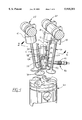
- FIG. 1 is a partial isometric view of an insulated pre-combustion chamber installed in a radial-valve cylinder head;
- FIG. 2 is a cross-sectional view of the insulated pre-combustion chamber taken along line 2--2 of FIG. 1 and showing in part the structure of the cylinder head that encapsulates the pre-combustion chamber;
- FIG. 3 is an enlarged view of the circled area of FIG. 2;
- FIG. 4 is a modification of the pre-combustion chamber shown in FIGS. 1-3;
- FIG. 5 is a side elevational view of the lower housing member of the pre-combustion chamber seen in FIGS. 1-3 and FIG. 4 surrounded by an insulation member;
- FIG. 6 is an exploded view showing the various parts of the insulated pre-combustion chamber of FIGS. 1-3;
- FIG. 7 is an elevational view partially in section showing a pre-combustion chamber similar to that seen in FIGS. 1-3 incorporated with a fuel injector in a valveless two cycle engine;
- FIG. 8 is an elevational view similar to the view seen in FIG. 7 except that the support for the fuel injector is provided with internal passages for the return of leak-off fuel;
- FIG. 9 is a further modified version of the pre-combustion chamber of FIGS. 1-3 for use on four or two cycle engines that operate on the spark-gas (natural gas) combustion system.
- FIG. 1 a partial perspective view is shown of the combustion system components of a four-cycle IDI engine utilizing four radial valves 10, 12, 14, and 16.
- the valves 10 and 12 are intake valves while the valves 14 and 16 are exhaust valves each of which is driven directly through a special inverted bucket tappet 18 by double overhead camshafts (DOHC) 20 and 22 as described in my U.S. Pat. No. 5,570,665 issued on Nov. 5, 1996.
- DOHC double overhead camshafts
- the valves 10-16 as well as a pre-combustion chamber 24 and a fuel injector 26 are disposed in a cylinder head 28 (seen in FIG. 2) which is secured to an engine block (not shown).
- the pre-combustion chamber 24 has its longitudinal center axis substantially centered with the axial centerline of a piston 30 which is disposed for reciprocal movement within a cylinder (not shown) forming part of the engine block.
- the lower section of the fuel injector 26 is shown, composed of the lower part of a nozzle holder 32 and an nozzle tip 34 firmly attached to the holder 32 by a threadably disposed tip nut 36 engaging the nozzle holder 32.
- the injector 26 is aligned substantially vertically and centrally with respect to the pre-combustion chamber 24 with a gasket 38 disposed between the flat bottom of the tip nut 36 and the upper flat surface of the pre-combustion chamber 24.
- the injector 26 can be secured in place by a variety of common means, none of which is shown. Also, common means of supplying fuel to the injector 26 and returning injector leak-off fuel to the fuel tank, are not shown.
- a glow plug 40 is provided with its tip 42 protruding into the inner cell area of the pre-combustion chamber 24 through a hole 43 formed in the side wall of the pre-combustion chamber 24. The glow plug 40 is inserted through a boss 44 (FIG. 5) integrally formed with the lower portion of the pre-combustion chamber 24.
- the large body of the glow plug 40 is secured by threads 41 to a proper boss cast integrally with the cylinder head 28 of parent-metal such as aluminum or iron.
- FIG. 2 is a cross-sectional view taken on line 2--2 passing through valves 10 and 16 and through the cylinder head 28 as shown in FIG. 1.
- the valves 10, 16 are not shown in FIG. 2 although the cavities into which these components would be disposed are shown.
- the pre-combustion chamber 24, according to the present invention is encapsulated within the cylinder head 28 and includes three metal parts, namely, a lower housing member 46, an upper housing member 48, and a retainer member 50.
- the lower housing member 46 is larger in diameter at its upper end than it is at its lower end and terminates with a plurality of transfer passages 52 formed in the lower end of the lower housing member 46.
- the transfer passages provide communication between the inner cell area of the pre-combustion chamber 24 and the main combustion chamber formed between the top of the piston 30 and the cylinder head 28.
- the transfer passages 52 are circumferentially spaced about the longitudinal center axis of the pre-combustion chamber 24 and can be of the type and number as disclosed in my aforementioned U.S. Pat. No. 5,392,744.
- the upper housing member 48 is formed with a tubular collar 54 that accommodates the injector tip 34 and is integral with a depending circular stem portion 56.
- the retainer member 50 has a cylindrical skirt portion 58 merging with an upper ring section 60 which defines a circular opening 59 adapted to mate with and surround the collar section 54.
- the upper end of the lower housing member 46 and the lower end of the skirt portion 58 of the retainer member 50 are piloted by the stem portion 56 of the upper housing member 48.
- a flat bottom surface 61 formed at the lower end of the skirt portion 58 of the retainer member 50 abuts a flat top surface 62 of the lower housing member 46 to maintain proper height between the retainer member 50 and the lower housing member 46.
- a flat bottom surface 64 of the upper housing member 48 abuts a flat stepped surface 66 counter-bored in the upper end of the lower housing member 46. In this way, a cavity of controlled height is formed between the upper internal surface 67 of the retainer member 50 and the outer upper surface 69 of the upper housing member 48 as seen in FIG. 2.
- the top flat upper surface 68 of the retainer member 50 is positioned in horizontal alignment with the top flat upper surface 70 of the collar 54.
- the design of the lower and upper housing members 46 and 48 and the retainer member 50 is such as to provide proper alignment of the parts during a joining process (such as electron-beam) so as to provide a metallic single-piece pre-combustion chamber as seen in FIG. 2.
- a washer-shaped insulation member 72 is placed over the collar 54 onto the outer upper surface 69 of the upper housing member 48.
- the retainer member 50 is then placed over the insulation member 72 and the lower housing member 46 is connected to the upper housing member 48 and the retainer member 50 to provide the interlocking joint seen in FIG. 3.
- the insulation member 72 occupies the aforementioned cavity between the retainer member 50 and the upper housing member 48 and is completely encapsulated between the two metallic members.
- a cone-shaped insulation member 74 is fitted to the lower housing member 46 and bonded or glued thereto using a high temperature resistant adhesive so as to maintain the insulation member 74 in the position shown relative to the lower housing member 46.
- Each of the insulation members 72 and 74 can be made of a flexible high-temperature ceramic mat such as produced by 3M Company of Minneapolis, Minn. and which, I believe, is known as either "Ceramatt” or "Ceramet". If preferred, the insulation members 72 and 74 can be made of solid high temperature ceramic. Any other well known high temperature resistant material having insulating properties can be used. Conversely, the top insulation member 72, if desired, can be disposed of to rely only on the insulation properties of the air cavity into which it is normally inserted. The thickness of each of the insulation members should be sufficient so that at least 50 to 75 percent or a majority of the heat generated within the pre-combustion chamber can be retained.
- the pre-combustion chamber 24 is combined with the insulation members 72 and 74 as explained above, the entire assembly is then placed in a casting flask in the form of a solid core and cast integrally with the cylinder head 28. In this manner, the pre-combustion chamber 24 together with the insulation members 72 and 74 become part of a single integral unit.
- the pre-combustion chamber 24 is firmly retained in the cylinder head casting 28, by having part of the casting covering a shoulder 76 of the retainer member 50 and cooperating with the tapered conical design of the lower housing member 46.
- FIG. 5 shows one configuration of the insulation member 74 if it should be made of solid ceramics.
- a U-shaped notch 78 is provided in the upper section of the insulation member 74 through which the boss 44 extends sideways from the lower housing member 46.
- a boss such as boss 44 would be provided when the wall of the member 46 is too thin to allow a tapered glow plug seat to be machined directly on it as described above.
- the boss 44 has a conical seat 80 for the end-body of the glow plug 40 to seal the pre-combustion chamber 24 against leakage through the outside of the glow plug 40.
- An alternative design for the insulation member 74 would be to make the insulation member 74 in two pieces, split down the center of the boss 44 so as to allow proper insulation above the boss 44.
- Another alternative solution is to use the configuration shown in FIG. 5 for the basic coverage of the lower housing member 46 in conjunction with a smaller piece bonded to member 46 to fill the empty space above the boss 44.
- the fuel injector 26 can be guided into the hole 82 (FIG. 2) in the cylinder head 28 with the nozzle tip 34 extending into the annular opening defined by the collar 54.
- the injector 26 is then tightly secured to an upper portion of the cylinder head 28 so as to exert a downward force on the pre-combustion chamber 24 and seal its tapered lower body against the surrounding cast walls of the cylinder head structure.
- the intent is to prevent leakage of combustion gases into the main combustion chamber past the pre-combustion chamber 24 and the injector 26, as well as to prevent lubricating oil above the cylinder head 28 from penetrating down and entering the main combustion chamber.
- FIG. 4 A modified version of the pre-combustion chamber 24 is shown in FIG. 4 and is identified by the reference numeral 86. It will be noted that the parts of the pre-combustion chamber 86 that are structurally the same as those of the pre-combustion chamber 24 will be identified by the same reference numerals but primed.
- the lower housing member 46' has its upper end rigidly secured to the lower end of an upper housing member 88 by an interlocking connection similar to that provided in the pre-combustion chamber 24 between the upper and lower housing members 48 and 48.
- the upper housing member 88 is not combined with a retainer member such as the retainer member 50 provided in the pre-combustion chamber 24.
- the upper housing member 88 is generally shaped as a spool having an enlarged head 90 which cooperates with a stem portion 92 to define an annular groove 94.
- the stem portion 92 is piloted into the upper end of the lower housing member 46' to assure alignment of the housing members 46' and 88 during assembly.
- the head 90 of the housing member 88 provides a solid flat seat or surface 95 for the injector nut gasket (not shown) and has a diameter greater than the diameter of the opening 82'. Also, a shoulder portion 96 at the periphery of the head serves as an anchor point for the pre-combustion chamber 86 by trapping it into the cast structure of the cylinder head 28'.
- an inverted L-shaped ceramic insulation member 98 has an arm portion 98a which extends into the groove 94 and a leg portion 98b which covers the stem portion 92 of the upper housing member 88.
- the lower housing member 46' has its upper tapered portion covered by a cone-shaped insulation member 74'.
- the insulation member 98 will be made as two parts so it can be assembled onto the upper housing member 88 and is in direct contact with the metal of the cylinder head 28'.
- both insulation members 74' and 98 would be bonded to the respective housing members 46' and 88 prior to having the cylinder head 28' cast around the pre-combustion chamber 86.
- FIG. 7 shows a pre-combustion chamber arrangement primarily, but not exclusively, intended for valveless two-cycle engines in which there is no "overhead" cylinder head of the type seen in FIGS. 1-4.
- the fuel injector system can be exposed to the atmosphere.
- the pre-combustion chamber shown is removable in its entirety to simplify the development process and service.
- this pre-combustion chamber consists of three metal parts, two of which are essentially the same in construction as two of the parts of the pre-combustion chamber 24. Accordingly, those parts of the FIG. 7 pre-combustion chamber arrangement that are essentially the same as the parts of the pre-combustion chamber arrangement of FIGS. 1-3 will be identified by the same reference numerals but in this case will be double primed.
- the pre-combustion chamber shown includes a lower housing member 46", an upper housing member 48", and a retainer member 100 all of which are joined together and rigidly interconnected through a welding operation as explained above in connection with the pre-combustion chamber 24.
- the pre-combustion chamber is designed for slidable installation into a machined cylindrical cavity 102 formed in an upstanding boss 104 which is an integral part of a cylinder head structure 106.
- the cylindrical outer surface of the retainer member 100 is formed with an annular groove having an "O" ring 110 made of high temperature resistant silicone rubber.
- a ring-like groove is provided in the top surface of the retainer member 100 for a soft-metal ring 116.
- the "O" ring 110 seals against the smooth interior surface of the cylindrical cavity 102 in the boss 104; but the metal ring 116 seals the opening 112 by having a lower end 120 of the injector holder 114 extending downward in sealing engagement with the metal ring 116.
- the lower insulation member 122 adjacent the housing member 46" has a slightly different exterior shape than the insulation member 74, however, the upper insulation member 72" would be identical in configuration as the insulation member 72 incorporated with the pre-combustion chamber 24.
- the injector holder 114 is a separate unit, solidly attached to the cylinder head by hold-down bolts 124 (only one shown) through ears 126 (only one shown) extending outwardly from the main body of the holder 114.
- An "O" ring 128, disposed in a groove machined on the outside diameter of the holder 114 prevents coolant leakage from the cooling jacket chamber 108 to the atmosphere.
- the fuel injector 26" is threadably attached to the upper portion of the injector holder 114 by the injector hold-down nut 130 or by other conventional methods well known to those versed in the practice of engine design.
- High-pressure fuel is fed to the injector 26" by a pump (not shown) and through a fuel line 132 attached to an injector fitting 134 by a line-nut 136.
- Nozzle leak-off fuel is conventionally collected by a system of low pressure tubing 138.
- One branch of the tubing 138 is attached to the fuel injector 26" by a banjo bolt 139 threadably inserted in a hole (not shown) which, in turn, connects with the fuel return passage (not shown) drilled inside the nozzle holder.
- FIG. 8 shows a pre-combustion chamber arrangement and a fuel injector arrangement that is substantially identical to that shown in FIG. 7 but offers an alternative solution to the fuel return problem, applicable to any kind of diesel engine, with any type of valve train.
- This modification results in a lower cost arrangement than the fuel return arrangement seen in FIG. 7, and avoids the possibility, on engines having a valve train, of having fuel leaking into the overhead and contaminating the lubricating oil or leaking to the ambient in case of two-cycle valveless engines.
- the parts seen in FIG. 8 that correspond to the parts seen in FIG. 7 are identified by corresponding reference numerals but are triple primed.
- a modified injector holder 140 allows the return of the injector leak-off fuel through the tank in a novel fashion.
- the modified fuel leak-off passages and sealing-control are affected by modifying the injector body internally so that its fuel leak-off is accomplished through a hole drilled radially at a much lower point in the holder 140 than is shown in FIG. 7 for the case of the banjo bolts 139.
- Fuel return holes so repositioned, low on the holder 140, are being used today in new cylinder head designs that properly seal the injector from leakage around its body and in which the hole registers directly, without going through an intermediate piece (such as a nozzle holder) with a matching hole drilled through dedicated bosses cast integrally in the cylinder head structure and joined all together by a master passage or gallery through which the fuel is conducted to a point on an outside wall of the head. At that point, a fitting is installed to connect the fuel return lines back to the fuel tank.
- an intermediate piece such as a nozzle holder
- the novel feature of the fuel return arrangement shown in FIG. 8 is that, with the repositioned leak-off hole as described above, the modified injector holder 140 is formed with a vertical hole or passage 142 drilled through its thick wall parallel to its longitudinal centerline prior to machining its female thread 144 for the injector hold-down nut 130'". Hole 142 is drilled to a depth where it connects with a short hole 148 that registers with an annular groove 149 to provide constant registration with the gallery branch passage 150, which in turn, is in fluid connection with a main gallery (not shown) through which all the fuel from the individual injector leak-off holes returns to the fuel tank.
- Another hole 152 is drilled radially through the thick outside wall of the injector holder 140, completing the continuous fluid connection between the fuel leak-off hole 161 in the nozzle holder 155 and the fuel tank (not shown).
- Appropriate plugs 158 and 160 seal the unused open ends of holes 142 and 152, respectively.
- the novelty of this embodiment consists of the series of drilled holes 142, 148, 152 and "O" rings 162, 164, 166, 168, disposed in the injector 26'" and injector holder 140 to provide the appropriately sealed fluid passages needed to close the circuit to the fuel tank.
- FIG. 9 shows a two-piece pre-combustion chamber arrangement which includes an upper housing member 170 rigidly connected to a lower housing member 172.
- the housing members 170 and 172 are modified for use on both four and two-cycle engines, with or without valves, that operate on the spark-gas combustion system and that use a pre-combustion chamber to control emissions, especially NO x .
- the pre-combustion chamber is located in a multi-dimensional cavity 174 machined through the height of the walls of a cylinder head structure 176.
- the upper housing member 170 is provided with a flat top surface 171 of a diameter substantially equal to the diameter of the upper portion of the cavity 174.
- the lower housing member 172 is generally conical in configuration with its lower end being provided with transfer passages 177 connecting the pre-combustion chamber with the main combustion chamber.
- the lower housing member 172 is formed with a radially outwardly extending flange 178 abutting a shoulder formed as part of the cylinder head 176 with a metal gasket 180 placed therebetween to prevent leakage of combustion gases out of the main combustion chamber.
- the upper housing member 170 is piloted into the upper end of the lower housing member 172 so as to assure alignment during assembly of the housing members.
- a single cone-shaped insulation member 182 is positioned so that it covers most of the lower housing member 172 and extends above the latter member to cover the outer side-wall of the upper housing member 170. As shown, the entire body of the insulation member 182 is in direct contact with the metal of cylinder head 176.
- the upper and lower housing members 170 and 172 are joined together through the manufacturing interlocks as provided in the pre-combustion chamber 86 disclosed in FIG. 4 hereof. As in the case of the pre-combustion chambers of FIGS. 7 and 8, the pre-combustion chamber, composed of the upper and lower housing members 170 and 172, is not retained within the cylinder head 176 through a casting operation.
- the pre-combustion chamber is located within the machined cavity 174 in the cylinder head and, in this case, is tightly supported in place by a holder member or bushing 184.
- the bushing 184 is threadably secured by threads 185 to the upper part of the cavity 174 with a O-ring type seal 194 interposed therebetween, and has its lower flat bottom surface abutting the aforementioned flat top surface 171 of the upper housing member 170.
- a metal ring 186 is located between the two surfaces so as to seal the pre-combustion chamber from leakage.
- the hollow bushing 184 is provided with internal threads 188 at its lower end to receive a spark plug the spark producing portion of which would be positioned within a circular opening 189 centrally formed in the upper housing member 170.
- spark-ignited gas engines present unusual and somewhat contradictory requirements. For example, whereas it is necessary to reduce the heat losses from the pre-combustion chamber, the spark plug itself must be cooled to eliminate the possibility of it becoming so hot that it acts as a glow plug to ignite the mixture uncontrollably. This could force the designer to eliminate the top pre-combustion chamber insulation and provide good cooling for the spark-plug. In this instance, however, a sizeable length of the spark-plug bushing 184 is exposed to the cooling jacket chamber 190 through the upper walls of the cavity 174. Since this type of engine ignites the fuel with a spark and not by compression-ignition, a glow-plug as previously shown in connection with the diesel engines is not necessary, but a small gas feed hole is required.
- a hole 192 normally for a glow plug is modified to provide gas to the cell area of the pre-combustion chamber.
- a conventional arrangement with a gas line and valve (both not shown) are disposed in fluid connection with hole 192.
- This type of pre-combustion chamber when used for two-cycle loop-scavenged (valveless) spark-ignited gas engines and if desired, can have more than the four transfer passages communicating with the main combustion chamber of the engine as shown in my aforementioned '744 patent. Since these engines are typically used for long-service life in industrial applications, the threaded, removable disposition of the pre-combustion chamber facilitates repairs or replacements.
Abstract
Description
Claims (8)
Priority Applications (1)
| Application Number | Priority Date | Filing Date | Title |
|---|---|---|---|
| US08/847,266 US5915351A (en) | 1997-02-24 | 1997-05-01 | Insulated precombustion chamber |
Applications Claiming Priority (2)
| Application Number | Priority Date | Filing Date | Title |
|---|---|---|---|
| US3826597P | 1997-02-24 | 1997-02-24 | |
| US08/847,266 US5915351A (en) | 1997-02-24 | 1997-05-01 | Insulated precombustion chamber |
Publications (1)
| Publication Number | Publication Date |
|---|---|
| US5915351A true US5915351A (en) | 1999-06-29 |
Family
ID=26715029
Family Applications (1)
| Application Number | Title | Priority Date | Filing Date |
|---|---|---|---|
| US08/847,266 Expired - Lifetime US5915351A (en) | 1997-02-24 | 1997-05-01 | Insulated precombustion chamber |
Country Status (1)
| Country | Link |
|---|---|
| US (1) | US5915351A (en) |
Cited By (24)
| Publication number | Priority date | Publication date | Assignee | Title |
|---|---|---|---|---|
| US20050217639A1 (en) * | 2002-10-02 | 2005-10-06 | Hill Phillip G | Glow ring ignition assist for internal combustion engine |
| WO2007087184A3 (en) * | 2006-01-20 | 2007-12-27 | Cameron Int Corp | Bolted pre-combustion chamber |
| US20090151708A1 (en) * | 2007-12-14 | 2009-06-18 | Schouweiler Jr David J | Internal combustion engine having a selectively insulated combustion chamber |
| US20100300417A1 (en) * | 2008-12-12 | 2010-12-02 | Schouweiler Jr David J | Internal combustion engine having a transitionally segregated combustion chamber |
| US20110036065A1 (en) * | 2009-08-11 | 2011-02-17 | Yen Wen Wong | Lawn mower powered by a compression-ignited combustion engine that can use multiple fuel types |
| US20110067675A1 (en) * | 2009-09-02 | 2011-03-24 | Bernd Streicher | Fuel injection assembly with optimized heat coupling between fuel injection device and cylinder head |
| US20110146618A1 (en) * | 2009-12-22 | 2011-06-23 | Lapointe Leon A | Pre-combustion device for an internal combustion engine |
| US20140069370A1 (en) * | 2008-03-12 | 2014-03-13 | Cameron International Corporation | Pre-chamber |
| US20140360456A1 (en) * | 2013-06-05 | 2014-12-11 | Pratt & Whitney Canada Corp. | Rotary Internal Combustion Engine With Pilot Subchamber And Ignition Element |
| US20150184578A1 (en) * | 2012-09-20 | 2015-07-02 | Mitsubishi Heavy Industries ,Ltd. a corporation | Precombustion chamber gas engine |
| EP2977582A1 (en) * | 2014-07-22 | 2016-01-27 | Caterpillar Energy Solutions GmbH | Ignition device with pre-combustion chamber |
| US9631579B1 (en) * | 2014-08-21 | 2017-04-25 | Charles S. Powers | Seal assemblies and methods for removable precombustion chamber tip |
| US9677459B2 (en) | 2008-03-12 | 2017-06-13 | Ge Oil & Gas Compression Systems, Llc | Internal combustion engine with shrouded injection valve and precombustion chamber system |
| US20170211499A1 (en) * | 2016-01-25 | 2017-07-27 | Toyota Jidosha Kabushiki Kaisha | Internal combustion engine |
| US9915190B2 (en) * | 2015-07-13 | 2018-03-13 | Caterpillar, Inc. | Ducted combustion systems utilizing Venturi ducts |
| US9920684B2 (en) | 2012-11-07 | 2018-03-20 | Dave Schouweiler | Fuel-stratified combustion chamber in a direct-injected internal combustion engine |
| US20180106182A1 (en) * | 2016-10-14 | 2018-04-19 | Caterpillar Inc. | Prechamber ignition device for internal combustion engine, and method |
| CN110107392A (en) * | 2018-02-01 | 2019-08-09 | Ge延巴赫两合无限公司 | Pre-chamber arrangement for combustion engine |
| CN112211720A (en) * | 2019-07-11 | 2021-01-12 | 曼能源解决方案公司(德国曼能源解决方案股份公司子公司) | Internal combustion engine |
| US20210131336A1 (en) * | 2018-07-12 | 2021-05-06 | Radical Combustion Technologies, Llc | Systems, apparatus, and methods for increasing combustion temperature of fuel-air mixtures in internal combustion engines |
| US11118498B2 (en) * | 2014-08-23 | 2021-09-14 | Tracy Northington | Pre-combustion chamber apparatus and method for pre-combustion |
| CN113944540A (en) * | 2020-07-17 | 2022-01-18 | 广州汽车集团股份有限公司 | Engine pre-combustion chamber structure, engine and automobile with engine pre-combustion chamber structure |
| US11459976B2 (en) * | 2018-09-14 | 2022-10-04 | Avl List Gmbh | Cylinder head |
| US11512625B2 (en) * | 2019-04-22 | 2022-11-29 | Mitsubishi Heavy Industries Engine & Turbocharger, Ltd. | Precombustion chamber engine |
Citations (7)
| Publication number | Priority date | Publication date | Assignee | Title |
|---|---|---|---|---|
| US4426966A (en) * | 1981-06-12 | 1984-01-24 | Mtu Motoren-Und Turbinen-Union | Precombustion chamber in the cylinder head of a diesel engine |
| US4511612A (en) * | 1981-08-21 | 1985-04-16 | Motoren-Und Turbinen-Union Munchen Gmbh | Multiple-layer wall for a hollow body and method for manufacturing same |
| US4513708A (en) * | 1979-04-21 | 1985-04-30 | Robert Bosch Gmbh | Method for igniting lean fuel-air mixtures and an apparatus to perform the method |
| US4672933A (en) * | 1984-10-30 | 1987-06-16 | 501 NGK Spark Plug Co. Ltd. | Precombustion chamber with insulating means |
| US4699102A (en) * | 1985-07-30 | 1987-10-13 | Ngk Spark Plug Co., Ltd. | Structure for mounting sub-combustion chamber in an internal combustion engine |
| US5392744A (en) * | 1993-03-12 | 1995-02-28 | Chrysler Corporation | Precombustion chamber for a double overhead camshaft internal combustion engine |
| US5570665A (en) * | 1995-04-04 | 1996-11-05 | Chrysler Corporation | Valve train for internal combustion engine |
-
1997
- 1997-05-01 US US08/847,266 patent/US5915351A/en not_active Expired - Lifetime
Patent Citations (7)
| Publication number | Priority date | Publication date | Assignee | Title |
|---|---|---|---|---|
| US4513708A (en) * | 1979-04-21 | 1985-04-30 | Robert Bosch Gmbh | Method for igniting lean fuel-air mixtures and an apparatus to perform the method |
| US4426966A (en) * | 1981-06-12 | 1984-01-24 | Mtu Motoren-Und Turbinen-Union | Precombustion chamber in the cylinder head of a diesel engine |
| US4511612A (en) * | 1981-08-21 | 1985-04-16 | Motoren-Und Turbinen-Union Munchen Gmbh | Multiple-layer wall for a hollow body and method for manufacturing same |
| US4672933A (en) * | 1984-10-30 | 1987-06-16 | 501 NGK Spark Plug Co. Ltd. | Precombustion chamber with insulating means |
| US4699102A (en) * | 1985-07-30 | 1987-10-13 | Ngk Spark Plug Co., Ltd. | Structure for mounting sub-combustion chamber in an internal combustion engine |
| US5392744A (en) * | 1993-03-12 | 1995-02-28 | Chrysler Corporation | Precombustion chamber for a double overhead camshaft internal combustion engine |
| US5570665A (en) * | 1995-04-04 | 1996-11-05 | Chrysler Corporation | Valve train for internal combustion engine |
Non-Patent Citations (6)
| Title |
|---|
| 960015, Design and Development of Three Combustion Systems for a Small Passenger Car Diesel Engine , Vladimir Kosina et al, pp. 1 18. No date. * |
| 960015, Design and Development of Three Combustion Systems for a Small Passenger-Car Diesel Engine, Vladimir Kosina et al, pp. 1-18. No date. |
| 960058, Rotular Tappet Valve Trains for Hemispherical Combustion Chambers , Jose F. Regueiro et al, pp. 1 16. No date. * |
| 960058, Rotular Tappet™ Valve Trains for Hemispherical Combustion Chambers, Jose F. Regueiro et al, pp. 1-16. No date. |
| Combustion and Combustion Chamber for a Low Heat Rejection Engine , Hideo Kawamura et al, pp. 1 9. No date. * |
| Combustion and Combustion Chamber for a Low Heat Rejection Engine, Hideo Kawamura et al, pp. 1-9. No date. |
Cited By (37)
| Publication number | Priority date | Publication date | Assignee | Title |
|---|---|---|---|---|
| US7281514B2 (en) * | 2002-10-02 | 2007-10-16 | Westport Power Inc. | Glow ring ignition assist for internal combustion engine |
| US20050217639A1 (en) * | 2002-10-02 | 2005-10-06 | Hill Phillip G | Glow ring ignition assist for internal combustion engine |
| NO343288B1 (en) * | 2006-01-20 | 2019-01-21 | Ge Oil & Gas Compression Systems Llc | Bolt pre-combustion chamber |
| WO2007087184A3 (en) * | 2006-01-20 | 2007-12-27 | Cameron Int Corp | Bolted pre-combustion chamber |
| US20090151708A1 (en) * | 2007-12-14 | 2009-06-18 | Schouweiler Jr David J | Internal combustion engine having a selectively insulated combustion chamber |
| US9670827B2 (en) | 2008-03-12 | 2017-06-06 | Ge Oil & Gas Compression Systems, Llc | Pre-chamber |
| US20140069370A1 (en) * | 2008-03-12 | 2014-03-13 | Cameron International Corporation | Pre-chamber |
| US9745891B2 (en) | 2008-03-12 | 2017-08-29 | Ge Oil & Gas Compression Systems, Llc | Internal combustion engine with shrouded injection valve and precombustion chamber system |
| US9677459B2 (en) | 2008-03-12 | 2017-06-13 | Ge Oil & Gas Compression Systems, Llc | Internal combustion engine with shrouded injection valve and precombustion chamber system |
| US9222402B2 (en) * | 2008-03-12 | 2015-12-29 | Ge Oil & Gas Compression Systems, Llc | Pre-chamber |
| US20100300417A1 (en) * | 2008-12-12 | 2010-12-02 | Schouweiler Jr David J | Internal combustion engine having a transitionally segregated combustion chamber |
| US20110036065A1 (en) * | 2009-08-11 | 2011-02-17 | Yen Wen Wong | Lawn mower powered by a compression-ignited combustion engine that can use multiple fuel types |
| US20120110966A1 (en) * | 2009-08-11 | 2012-05-10 | Yen Wen Wong | Lawn mower powered by a compression-ignition combustion engine that utilizes multiple fuel types |
| US20110067675A1 (en) * | 2009-09-02 | 2011-03-24 | Bernd Streicher | Fuel injection assembly with optimized heat coupling between fuel injection device and cylinder head |
| US8662053B2 (en) * | 2009-12-22 | 2014-03-04 | Cummins Inc. | Pre-combustion device for an internal combustion engine |
| US20110146618A1 (en) * | 2009-12-22 | 2011-06-23 | Lapointe Leon A | Pre-combustion device for an internal combustion engine |
| US20150184578A1 (en) * | 2012-09-20 | 2015-07-02 | Mitsubishi Heavy Industries ,Ltd. a corporation | Precombustion chamber gas engine |
| US10202891B2 (en) * | 2012-09-20 | 2019-02-12 | Mitsubishi Heavy Industries, Ltd. | Precombustion chamber gas engine |
| US9920684B2 (en) | 2012-11-07 | 2018-03-20 | Dave Schouweiler | Fuel-stratified combustion chamber in a direct-injected internal combustion engine |
| US20140360456A1 (en) * | 2013-06-05 | 2014-12-11 | Pratt & Whitney Canada Corp. | Rotary Internal Combustion Engine With Pilot Subchamber And Ignition Element |
| US9334794B2 (en) * | 2013-06-05 | 2016-05-10 | Pratt & Whitney Canada Corp. | Rotary internal combustion engine with pilot subchamber and ignition element |
| EP2977582A1 (en) * | 2014-07-22 | 2016-01-27 | Caterpillar Energy Solutions GmbH | Ignition device with pre-combustion chamber |
| US9732664B2 (en) | 2014-07-22 | 2017-08-15 | Caterpillar Energy Solutions Gmbh | Ignition device with pre-combustion chamber |
| US9631579B1 (en) * | 2014-08-21 | 2017-04-25 | Charles S. Powers | Seal assemblies and methods for removable precombustion chamber tip |
| US11118498B2 (en) * | 2014-08-23 | 2021-09-14 | Tracy Northington | Pre-combustion chamber apparatus and method for pre-combustion |
| US9915190B2 (en) * | 2015-07-13 | 2018-03-13 | Caterpillar, Inc. | Ducted combustion systems utilizing Venturi ducts |
| US9970378B2 (en) * | 2016-01-25 | 2018-05-15 | Toyota Jidosha Kabushiki Kaisha | Internal combustion engine |
| US20170211499A1 (en) * | 2016-01-25 | 2017-07-27 | Toyota Jidosha Kabushiki Kaisha | Internal combustion engine |
| US20180106182A1 (en) * | 2016-10-14 | 2018-04-19 | Caterpillar Inc. | Prechamber ignition device for internal combustion engine, and method |
| US10273869B2 (en) * | 2016-10-14 | 2019-04-30 | Caterpillar Inc. | Prechamber ignition device for internal combustion engine, and method |
| CN110107392A (en) * | 2018-02-01 | 2019-08-09 | Ge延巴赫两合无限公司 | Pre-chamber arrangement for combustion engine |
| US20210131336A1 (en) * | 2018-07-12 | 2021-05-06 | Radical Combustion Technologies, Llc | Systems, apparatus, and methods for increasing combustion temperature of fuel-air mixtures in internal combustion engines |
| US11459976B2 (en) * | 2018-09-14 | 2022-10-04 | Avl List Gmbh | Cylinder head |
| US11512625B2 (en) * | 2019-04-22 | 2022-11-29 | Mitsubishi Heavy Industries Engine & Turbocharger, Ltd. | Precombustion chamber engine |
| CN112211720A (en) * | 2019-07-11 | 2021-01-12 | 曼能源解决方案公司(德国曼能源解决方案股份公司子公司) | Internal combustion engine |
| CN113944540A (en) * | 2020-07-17 | 2022-01-18 | 广州汽车集团股份有限公司 | Engine pre-combustion chamber structure, engine and automobile with engine pre-combustion chamber structure |
| CN113944540B (en) * | 2020-07-17 | 2023-02-28 | 广州汽车集团股份有限公司 | Engine pre-combustion chamber structure, engine and automobile with engine pre-combustion chamber structure |
Similar Documents
| Publication | Publication Date | Title |
|---|---|---|
| US5778849A (en) | Insulated precombustion chamber | |
| US5915351A (en) | Insulated precombustion chamber | |
| US7185614B2 (en) | Double bowl piston | |
| US4317438A (en) | High power output engine | |
| US7040279B2 (en) | Energy-cell combustion system | |
| US5392744A (en) | Precombustion chamber for a double overhead camshaft internal combustion engine | |
| US5735240A (en) | Direct injected engine | |
| US4248192A (en) | Internal combustion engine and method of operation thereof with isolated combustion initiation | |
| CN112879145B (en) | Jet valve controlled precombustion chamber ignition internal combustion engine | |
| US5309879A (en) | Double overhead camshaft four valve diesel engine with side prechamber | |
| US4532899A (en) | Internal combustion engine fuel-injection system | |
| EP1173662B1 (en) | Combustion method for an internal combustion engine | |
| US4223645A (en) | Combustion chamber of an internal combustion engine | |
| US5421301A (en) | Direct cylinder fuel injection system for internal combustion engines | |
| US20090217905A1 (en) | Direct injection type of diesel engine | |
| US5579734A (en) | Rotary valve internal combustion engine | |
| FR2650630A1 (en) | MULTI-CYLINDER ENGINE WITH FUEL INJECTION, COMPRISING FOUR VALVES PER CYLINDER | |
| Schäpertöns et al. | VW's gasoline direct injection (GDI) research engine | |
| US4237826A (en) | Multi-cylinder internal combustion engine equipped with an accumulation chamber | |
| US5417189A (en) | High speed indirect injection diesel engine | |
| US4378764A (en) | Piston and combustion chamber with improved fuel circulation | |
| US4178903A (en) | Internal combustion engine with an auxiliary combustion chamber | |
| US20210310401A1 (en) | Combustion-chamber structure of engine | |
| US6295961B1 (en) | Internal combustion rotating spherical head and valve | |
| US5115775A (en) | Internal combustion engine with multiple combustion chambers |
Legal Events
| Date | Code | Title | Description |
|---|---|---|---|
| AS | Assignment |
Owner name: CHRYSLER CORPORATION, MICHIGAN Free format text: ASSIGNMENT OF ASSIGNORS INTEREST;ASSIGNOR:REGUEIRO, JOSE F.;REEL/FRAME:008528/0384 Effective date: 19970430 |
|
| STCF | Information on status: patent grant |
Free format text: PATENTED CASE |
|
| FPAY | Fee payment |
Year of fee payment: 4 |
|
| FPAY | Fee payment |
Year of fee payment: 8 |
|
| AS | Assignment |
Owner name: WILMINGTON TRUST COMPANY, DELAWARE Free format text: GRANT OF SECURITY INTEREST IN PATENT RIGHTS - FIRST PRIORITY;ASSIGNOR:CHRYSLER LLC;REEL/FRAME:019773/0001 Effective date: 20070803 Owner name: WILMINGTON TRUST COMPANY,DELAWARE Free format text: GRANT OF SECURITY INTEREST IN PATENT RIGHTS - FIRST PRIORITY;ASSIGNOR:CHRYSLER LLC;REEL/FRAME:019773/0001 Effective date: 20070803 |
|
| AS | Assignment |
Owner name: WILMINGTON TRUST COMPANY, DELAWARE Free format text: GRANT OF SECURITY INTEREST IN PATENT RIGHTS - SECOND PRIORITY;ASSIGNOR:CHRYSLER LLC;REEL/FRAME:019767/0810 Effective date: 20070803 Owner name: WILMINGTON TRUST COMPANY,DELAWARE Free format text: GRANT OF SECURITY INTEREST IN PATENT RIGHTS - SECOND PRIORITY;ASSIGNOR:CHRYSLER LLC;REEL/FRAME:019767/0810 Effective date: 20070803 |
|
| AS | Assignment |
Owner name: DAIMLERCHRYSLER CORPORATION, MICHIGAN Free format text: CHANGE OF NAME;ASSIGNOR:CHRYSLER CORPORATION;REEL/FRAME:021826/0034 Effective date: 19981116 |
|
| AS | Assignment |
Owner name: CHRYSLER LLC, MICHIGAN Free format text: CHANGE OF NAME;ASSIGNOR:DAIMLERCHRYSLER COMPANY LLC;REEL/FRAME:021832/0233 Effective date: 20070727 Owner name: DAIMLERCHRYSLER COMPANY LLC, MICHIGAN Free format text: CHANGE OF NAME;ASSIGNOR:DAIMLERCHRYSLER CORPORATION;REEL/FRAME:021832/0256 Effective date: 20070329 |
|
| AS | Assignment |
Owner name: US DEPARTMENT OF THE TREASURY, DISTRICT OF COLUMBI Free format text: GRANT OF SECURITY INTEREST IN PATENT RIGHTS - THIR;ASSIGNOR:CHRYSLER LLC;REEL/FRAME:022259/0188 Effective date: 20090102 Owner name: US DEPARTMENT OF THE TREASURY,DISTRICT OF COLUMBIA Free format text: GRANT OF SECURITY INTEREST IN PATENT RIGHTS - THIR;ASSIGNOR:CHRYSLER LLC;REEL/FRAME:022259/0188 Effective date: 20090102 |
|
| AS | Assignment |
Owner name: CHRYSLER LLC, MICHIGAN Free format text: RELEASE BY SECURED PARTY;ASSIGNOR:US DEPARTMENT OF THE TREASURY;REEL/FRAME:022910/0273 Effective date: 20090608 |
|
| AS | Assignment |
Owner name: CHRYSLER LLC, MICHIGAN Free format text: RELEASE OF SECURITY INTEREST IN PATENT RIGHTS - FIRST PRIORITY;ASSIGNOR:WILMINGTON TRUST COMPANY;REEL/FRAME:022910/0498 Effective date: 20090604 Owner name: CHRYSLER LLC, MICHIGAN Free format text: RELEASE OF SECURITY INTEREST IN PATENT RIGHTS - SECOND PRIORITY;ASSIGNOR:WILMINGTON TRUST COMPANY;REEL/FRAME:022910/0740 Effective date: 20090604 Owner name: NEW CARCO ACQUISITION LLC, MICHIGAN Free format text: ASSIGNMENT OF ASSIGNORS INTEREST;ASSIGNOR:CHRYSLER LLC;REEL/FRAME:022915/0001 Effective date: 20090610 Owner name: THE UNITED STATES DEPARTMENT OF THE TREASURY, DIST Free format text: SECURITY AGREEMENT;ASSIGNOR:NEW CARCO ACQUISITION LLC;REEL/FRAME:022915/0489 Effective date: 20090610 Owner name: CHRYSLER LLC,MICHIGAN Free format text: RELEASE OF SECURITY INTEREST IN PATENT RIGHTS - FIRST PRIORITY;ASSIGNOR:WILMINGTON TRUST COMPANY;REEL/FRAME:022910/0498 Effective date: 20090604 Owner name: CHRYSLER LLC,MICHIGAN Free format text: RELEASE OF SECURITY INTEREST IN PATENT RIGHTS - SECOND PRIORITY;ASSIGNOR:WILMINGTON TRUST COMPANY;REEL/FRAME:022910/0740 Effective date: 20090604 Owner name: NEW CARCO ACQUISITION LLC,MICHIGAN Free format text: ASSIGNMENT OF ASSIGNORS INTEREST;ASSIGNOR:CHRYSLER LLC;REEL/FRAME:022915/0001 Effective date: 20090610 Owner name: THE UNITED STATES DEPARTMENT OF THE TREASURY,DISTR Free format text: SECURITY AGREEMENT;ASSIGNOR:NEW CARCO ACQUISITION LLC;REEL/FRAME:022915/0489 Effective date: 20090610 |
|
| AS | Assignment |
Owner name: CHRYSLER GROUP LLC, MICHIGAN Free format text: CHANGE OF NAME;ASSIGNOR:NEW CARCO ACQUISITION LLC;REEL/FRAME:022919/0126 Effective date: 20090610 Owner name: CHRYSLER GROUP LLC,MICHIGAN Free format text: CHANGE OF NAME;ASSIGNOR:NEW CARCO ACQUISITION LLC;REEL/FRAME:022919/0126 Effective date: 20090610 |
|
| FPAY | Fee payment |
Year of fee payment: 12 |
|
| AS | Assignment |
Owner name: CHRYSLER GROUP GLOBAL ELECTRIC MOTORCARS LLC, NORT Free format text: RELEASE BY SECURED PARTY;ASSIGNOR:THE UNITED STATES DEPARTMENT OF THE TREASURY;REEL/FRAME:026343/0298 Effective date: 20110524 Owner name: CHRYSLER GROUP LLC, MICHIGAN Free format text: RELEASE BY SECURED PARTY;ASSIGNOR:THE UNITED STATES DEPARTMENT OF THE TREASURY;REEL/FRAME:026343/0298 Effective date: 20110524 |
|
| AS | Assignment |
Owner name: CITIBANK, N.A., NEW YORK Free format text: SECURITY AGREEMENT;ASSIGNOR:CHRYSLER GROUP LLC;REEL/FRAME:026404/0123 Effective date: 20110524 |
|
| AS | Assignment |
Owner name: CITIBANK, N.A., NEW YORK Free format text: SECURITY AGREEMENT;ASSIGNOR:CHRYSLER GROUP LLC;REEL/FRAME:026435/0652 Effective date: 20110524 |
|
| AS | Assignment |
Owner name: JPMORGAN CHASE BANK, N.A., ILLINOIS Free format text: SECURITY AGREEMENT;ASSIGNOR:CHRYSLER GROUP LLC;REEL/FRAME:032384/0640 Effective date: 20140207 |
|
| AS | Assignment |
Owner name: FCA US LLC, MICHIGAN Free format text: CHANGE OF NAME;ASSIGNOR:CHRYSLER GROUP LLC;REEL/FRAME:035553/0356 Effective date: 20141203 |
|
| AS | Assignment |
Owner name: FCA US LLC, FORMERLY KNOWN AS CHRYSLER GROUP LLC, Free format text: RELEASE OF SECURITY INTEREST RELEASING SECOND-LIEN SECURITY INTEREST PREVIOUSLY RECORDED AT REEL 026426 AND FRAME 0644, REEL 026435 AND FRAME 0652, AND REEL 032384 AND FRAME 0591;ASSIGNOR:CITIBANK, N.A.;REEL/FRAME:037784/0001 Effective date: 20151221 |
|
| AS | Assignment |
Owner name: FCA US LLC (FORMERLY KNOWN AS CHRYSLER GROUP LLC), Free format text: RELEASE BY SECURED PARTY;ASSIGNOR:CITIBANK, N.A.;REEL/FRAME:042885/0255 Effective date: 20170224 |
|
| AS | Assignment |
Owner name: FCA US LLC (FORMERLY KNOWN AS CHRYSLER GROUP LLC), Free format text: RELEASE BY SECURED PARTY;ASSIGNOR:JPMORGAN CHASE BANK, N.A.;REEL/FRAME:048177/0356 Effective date: 20181113 |