EP2796849A2 - Vehicle Test Apparatus and Vehicle Test System - Google Patents
Vehicle Test Apparatus and Vehicle Test System Download PDFInfo
- Publication number
- EP2796849A2 EP2796849A2 EP20140165586 EP14165586A EP2796849A2 EP 2796849 A2 EP2796849 A2 EP 2796849A2 EP 20140165586 EP20140165586 EP 20140165586 EP 14165586 A EP14165586 A EP 14165586A EP 2796849 A2 EP2796849 A2 EP 2796849A2
- Authority
- EP
- European Patent Office
- Prior art keywords
- axles
- motion
- vehicle
- bases
- vehicle body
- Prior art date
- Legal status (The legal status is an assumption and is not a legal conclusion. Google has not performed a legal analysis and makes no representation as to the accuracy of the status listed.)
- Granted
Links
Images


Classifications
-
- G—PHYSICS
- G01—MEASURING; TESTING
- G01M—TESTING STATIC OR DYNAMIC BALANCE OF MACHINES OR STRUCTURES; TESTING OF STRUCTURES OR APPARATUS, NOT OTHERWISE PROVIDED FOR
- G01M17/00—Testing of vehicles
- G01M17/007—Wheeled or endless-tracked vehicles
-
- G—PHYSICS
- G01—MEASURING; TESTING
- G01M—TESTING STATIC OR DYNAMIC BALANCE OF MACHINES OR STRUCTURES; TESTING OF STRUCTURES OR APPARATUS, NOT OTHERWISE PROVIDED FOR
- G01M17/00—Testing of vehicles
- G01M17/007—Wheeled or endless-tracked vehicles
- G01M17/04—Suspension or damping
-
- G—PHYSICS
- G01—MEASURING; TESTING
- G01M—TESTING STATIC OR DYNAMIC BALANCE OF MACHINES OR STRUCTURES; TESTING OF STRUCTURES OR APPARATUS, NOT OTHERWISE PROVIDED FOR
- G01M17/00—Testing of vehicles
- G01M17/007—Wheeled or endless-tracked vehicles
- G01M17/06—Steering behaviour; Rolling behaviour
Definitions
- the invention relates to a vehicle test apparatus that conducts performance tests on automotive parts or vehicles, and a vehicle test system including the vehicle test apparatus.
- Japanese Patent Application Publication No. 2008-175778 describes a vehicle test apparatus including: a pair of front and rear transversely movable bases that are movable in the transverse direction; four groups of hydraulic cylinders that make motions of six degrees of freedom, the four groups of hydraulic cylinders consisting of two pairs of right and left groups of hydraulic cylinders disposed on the top face of the front transversely movable base and two pairs of right and left groups of hydraulic cylinders disposed on the top face of the rear transversely movable base; four swivel lift bases that are respectively connected to upper ends of the four groups of hydraulic cylinders; and four turning belts that are respectively provided on the four swivel lift bases and on which four wheels of a vehicle are disposed.
- Japanese Patent Application Publication No. 2006-138827 and Japanese Patent Application Publication No. 2009-536736 refer also to Japanese Patent Application Publication No. 2006-138827 and Japanese Patent Application Publication No. 2009-536736 .
- an inertial force acts on a vehicle body of the vehicle.
- an inertial force acts on a vehicle body of the vehicle.
- One object of the invention is to provide a vehicle test apparatus that is able to apply forces similar to inertial forces that are applied to a vehicle body of an actual vehicle while the actual vehicle is, for example, accelerating, decelerating or turning, to a vehicle body of a test article without causing the vehicle body of the test article to move relative to members that support wheels, and to provide a vehicle test system including the vehicle test apparatus.
- a vehicle test apparatus includes: a test article installation vehicle body to which four axles corresponding to four wheels that are a left front wheel, a right front wheel, a left rear wheel and a right rear wheel are attached, and on which a test article is installed; a first motion base that supports the test article installation vehicle body, and that allows the test article installation vehicle body to make motions of six degrees of freedom; and four second motion bases each of which supports a corresponding one of the axles, and each of which allows a corresponding one of the axles to make motions of six degrees of freedom.
- forces can be directly applied to the test article installation vehicle body by the first motion base in the state where the axles are supported by the second motion bases.
- forces similar to the inertial forces that are applied to the vehicle body of the actual vehicle during, for example, acceleration, deceleration, or turning of the actual vehicle can be applied to the test article installation vehicle body without causing the test article installation vehicle body to move relative to the members that support the wheels (axles).
- each of the motion bases may include a stationary base, a movable base disposed above the stationary base, and an actuator that is disposed between and connected to the stationary base and the movable base, and that allows the movable base to make motions of six degrees of freedom;
- the test article installation vehicle body may be disposed on the movable base of the first motion base and fixed to the movable base of the first motion base; and the axles may be supported by the corresponding movable bases of the second motion bases.
- the vehicle test apparatus may further include four electric motors that are connected to outer end portions of the respective axles, and that apply torques to the respective axles, and the axles may be supported by the corresponding movable bases of the second motion bases via motor bodies of the electric motors to which the corresponding axles are connected.
- the vehicle test apparatus may further include wheels that are connected to the respective axles so as to be rotatable together with the respective axles, and the axles may be supported by the corresponding movable bases of the second motion bases via the wheels to which the corresponding axles are connected.
- a vehicle test system includes: the vehicle test apparatus according to the above aspect; and a control unit that controls the motion bases.
- forces similar to the inertial forces that are applied to the vehicle body of the actual vehicle during, for example, acceleration, deceleration, or turning of the actual vehicle can be applied to the test article installation vehicle body without causing the test article installation vehicle body to move relative to the members that support the wheels (axles).
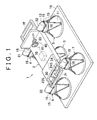
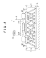
- a vehicle test apparatus 1 includes: a test article installation vehicle body 2 to which four axles 21S, 22S, 23S, 24S respectively corresponding to a left front wheel, a right front wheel, a left rear wheel and a right rear wheel are attached, and on which a test article is installed; a first motion base 3 that supports the test article installation vehicle body 2, and that causes the test article installation vehicle body 2 to make motions of six degrees of freedom; and four second motion bases 4, 5, 6, 7 that respectively support the axles 21S, 22S, 23S, 24S, and that respectively cause the axles 21S, 22S, 23S, 24S to make motions of six degrees of freedom.
- a front end of the test article installation vehicle body 2 is denoted by a reference symbol 2f, and a rear end thereof is denoted by a reference symbol 2r.
- No vehicle wheels are fitted to the four axles 21S, 22S, 23S, 24S of the test article installation vehicle body 2.
- Output shafts of four electric motors (hereinafter, referred to as "external force applying motors") 31, 32, 33, 34 that apply torques to the four axles 21S, 22S, 23S, 24S of the test article installation vehicle body 2 are connected to outer end portions of the four axles 21S, 22S, 23S, 24S of the test article installation vehicle body 2.
- the external force applying motors 31, 32, 33, 34 apply torques, which are similar to the torques (external forces) externally applied to axles of an actual vehicle when the actual vehicle is travelling, individually to the corresponding axles 21S, 22S, 23S, 24S.
- the external forces include, for example, rotational loads that are applied to the axles of the actual vehicle due to road surface frictions or the like when the actual vehicle is travelling, and torques that are applied to the axles via a road surface when the actual vehicle is travelling on a downhill slope.
- an electric power steering system (EPS) 40 and a rear wheel drive module 50 that drives the axle 23S for the left rear wheel and the axle 24S for the right rear wheel with the use of the electric motors are installed, as the test articles, on the test article installation vehicle body 2.
- the EPS 40 is a column assist-type EPS.
- the EPS 40 includes a steering wheel 81, a steering mechanism 82 that steers the front wheels in response to turning of the steering wheel 81, and a steering assist mechanism 83 that assists a driver in performing a steering operation.
- the steering mechanism 82 is not connected to the front wheels because no front wheels are provided.
- the steering wheel 81 and the steering mechanism 82 are mechanically linked to each other via a steering shaft.
- the steering mechanism 82 includes a rack-and-pinion mechanism including a pinion provided at a lower end of the steering shaft, and a rack shaft having a rack that is meshed with the pinion.
- the steering assist mechanism 83 includes an electric motor 41 (refer to FIG. 11 , hereinafter referred to as "assist motor 41") that generates a steering assist force, and a speed reduction mechanism (not illustrated) that transmits a torque output from the assist motor 41 to the steering shaft.
- the EPS 40 includes an ECU42 (refer to FIG. 11 , hereinafter referred to as "EPS ECU 42") that controls the assist motor 41, and a linear displacement sensor (not illustrated) that detects an axial displacement position of the rack shaft.
- the rear wheel drive module 50 includes an electric motor 51 (refer to FIG. 11 , hereinafter referred to as “rear wheel drive motor 51”) that rotates the axles 23S, 24S for the rear wheels, a transmission mechanism (not illustrated) that transmits a torque from the rear wheel drive motor 51 to the axles 23S, 24S for the rear wheels, an ECU 52 (refer to FIG.
- the transmission mechanism includes a clutch and a speed reduction mechanism. However, the transmission mechanism may include only one of the clutch and the speed reduction mechanism.
- each of the motion bases 3, 4, 5, 6, 7 is secured to a base plate 10 disposed on a floor.
- each of the motion bases 3, 4, 5, 6, 7 includes a stationary base 11 secured to the base plate 10, a movable base (moving base) 12 disposed above the stationary base 11, an actuator 13 that is disposed between and connected to the stationary base 11 and the movable base 12 and that causes the movable base 12 to make motions of six degrees of freedom (longitudinal, transverse, vertical, rolling, pitching and yawing motions), and a motion controller (not illustrated) that executes drive control of the actuator 13.
- the actuator 13 is composed of six electric cylinders.
- the test article installation vehicle body 2 is secured to the movable base 12 of the first motion base 3, with a center portion of the test article installation vehicle body 2 disposed on the movable base 12 of the first motion base 3. That is, the center portion of the bottom face of the test article installation vehicle body 2 is attached to the top face of the movable base 12 of the motion base 3.
- the external force applying motor 31 is mounted on the movable base 12 of the second motion base 4 on the left front side via a plurality of elastic bodies 15 and a motor attachment plate 16.
- the external force applying motor 32 is mounted on the movable base 12 of the second motion base 5 on the right front side via a plurality of elastic bodies 15 and a motor attachment plate 16.
- the external force applying motor 33 is mounted on the movable base 12 of the second motion base 6 on the left rear side via a plurality of elastic bodies 15 and a motor attachment plate 16.
- the external force applying motor 34 is mounted on the movable base 12 of the second motion base 7 on the right rear side via a plurality of elastic bodies 15 and a motor attachment plate 16.
- the external force applying motors 31, 32, 33, 34 are mounted on the movable bases 12 of the second motion bases 4, 5, 6, 7 with the same mounting structure.
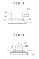
- the mounting structure for mounting the external force applying motor 32 on the movable base 12 of the second motion base 5 on the right front side will be described below in detail with reference to FIG. 5 to FIG. 7 .
- the motor attachment plate 16 is rectangular as viewed in a planar view.
- a motor body of the external force applying motor 32 is secured onto the motor attachment plate 16.
- the elastic bodies 15 that are circular as viewed in a planar view are attached to four corner portions of the bottom face of the motor attachment plate 16. That is, the four elastic bodies 15 are secured at their top faces to the four corner portions of the bottom face of the motor attachment plate 16 with adhesive.
- each of the elastic bodies 15 is secured to the top face of the movable base 12 of the second motion base 5 on the right front side with adhesive.
- the external force applying motor 32 is mounted on the movable base 12 of the second motion base 5 on the right front side via the four elastic bodies 15 and the motor attachment plate 16.
- the test article installation vehicle body 2 is supported by the first motion base 3.
- the external force applying motors 31, 32, 33, 34 are supported respectively by the second motion bases 4, 5, 6, 7.
- the outer end portions of the axles 21S, 22S, 23S, 24S are supported by the second motion bases 4, 5, 6, 7 via the external force applying motors 31, 32, 33, 34, respectively.
- various vehicle body postures can be created by executing drive control of the actuator 13 of the first motion base 3.
- various road surface conditions can be created by respectively executing drive control of the actuators 13 of the second motion bases 4, 5, 6, 7.
- individually controlling the actuators 13 of the motion bases 3, 4, 5, 6, 7, it is possible to simulate various vehicle travelling conditions.
- forces similar to the inertial forces that are applied to the vehicle body of the actual vehicle during, for example, acceleration, deceleration, or turning of the actual vehicle can be applied to the test article installation vehicle body 2 without causing the test article installation vehicle body 2 to move relative to the members that support the axles 21S, 22S, 23S, 24S.
- an X-axis denotes an axis that extends in the longitudinal direction of the vehicle body and passes through the center of gravity of the test article installation vehicle body 2
- a Y-axis denotes an axis that extends in the lateral direction of the vehicle body and passes through the center of gravity of the test article installation vehicle body 2
- a Z-axis denotes an axis that extends in the up-down direction of the vehicle body and passes through the center of gravity of the test article installation vehicle body 2.
- the X-axis, Y-axis and Z-axis belong to a coordinate system (hereinafter, referred to as vehicle body coordinate system) fixed to the test article installation vehicle body 2.
- FIG. 8A and FIG. 8B are schematic views for describing an example of the control of the motion bases 3, 4, 5, 6, 7 when a vehicle travelling condition during acceleration on a flat road is simulated.
- FIG. 8A illustrates a condition in which the vehicle is at a standstill on a flat road.
- the top faces of the movable bases 12 of the motion base 3, 4, 5, 6, 7 are parallel to the top face of the base plate 10.
- the heights of the movable bases 12 of the motion base 3, 4, 5, 6, 7 are adjusted such that an XY plane that is defined by the X-axis and the Y-axis of the vehicle body coordinate system is parallel to the top face of the base plate 10.
- the vehicle travelling condition during acceleration on a flat road can be created as follows. As illustrated in FIG. 8B , all the second motion bases 4, 5, 6, 7 are held in the standstill condition illustrated in FIG. 8A , and then the actuator 13 of the first motion base 3 is driven to rotate the movable base 12 of the first motion base 3 in a first direction (direction indicated by an arrow) around the Y axis.
- the first direction around the Y-axis is such a direction that the front end of the test article installation vehicle body 2 is lifted up.
- FIG. 9A and FIG. 9B are schematic views for describing an example of the control of the motion bases 3, 4, 5, 6, 7 when a vehicle travelling condition during acceleration on a slope is simulated. The case where the slope on which the vehicle is travelling is an uphill slope will be described.
- FIG. 9A illustrates a condition in which the vehicle is at a standstill on a slope.
- the top faces of the movable bases 12 of the motion bases 3, 4, 5, 6, 7 are parallel to the surface of the assumed slope.
- the heights of the movable bases 12 of the motion bases 3, 4, 5, 6, 7 are adjusted such that the XY plane defined by the X-axis and the Y-axis of the vehicle body coordinate system is parallel to the surface of the assumed slope.
- This standstill condition can be created from the standstill condition on a flat road in the following manner.
- the movable base 12 of the first motion base 3 is rotated by a prescribed degree in the first direction around the Y-axis in accordance with a slope angle of the slope.
- the movable bases 12 of the second motion bases 4, 5, 6, 7 are rotated by a prescribed degree in the first direction around the Y-axis in accordance with the slope angle of the slope, and are moved in the Z-axis direction (up-down direction).
- the first direction around the Y-axis is such a direction that the front end of the test article installation vehicle body 2 is lifted up.
- the movable bases 12 of the two second motion bases 4, 5 on the front side are moved upward, while the movable bases 12 of the two second motion bases 6, 7 on the rear side are moved downward.
- the vehicle travelling condition during acceleration on a slope can be created from the standstill condition illustrated in FIG. 9A in the following manner.
- the movable bases 12 of all the second motion bases 4, 5, 6, 7 are held in the standstill condition on the slope as illustrated in FIG. 9A , and the actuator 13 of the first motion base 3 is driven to rotate the movable base 12 of the first motion base 3 in the first direction (indicated by an arrow) around the Y-axis.
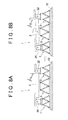
- FIG. 10A and FIG. 10B are schematic views for describing an example of the control of the motion bases 3, 4, 5, 6, 7 when a vehicle travelling condition during turning is simulated.
- FIG. 10A illustrates a condition in which the vehicle is travelling straight ahead.
- the movable base 12 of the first motion base 3 is rotated counterclockwise around the Z-axis as viewed in a planar view.
- the movable bases 12 of all the second motion bases, 4, 5, 6, 7 are rotated counterclockwise around the Z-axis as viewed in a plan view, and are moved in the XY plane defined by the X-axis and Y-axis of the vehicle body coordinate system in order to move the external force applying motors 31, 32, 33, 34 in accordance with the rotation of the test article installation vehicle body 2.
- the movable bases 12 of the second motion bases, 4, 5, 6, 7 are moved from positions indicated by two-dot chain lines to positions indicated by solid lines in FIG. 10B .
- the travelling condition during turning can be simulated. In this case, it is possible to evaluate axial loads applied to the axles 21S, 22S, 23S, 24S, a steering torque, a rack axis force, a hub bearings and the like.
- the external force applying motors 31, 32, 33, 34 to which the axles 21S, 22S, 23S, 24S are connected are respectively mounted on the second motion bases, 4, 5, 6, 7 via the elastic bodies 15.
- the errors can be absorbed through deformations of the elastic bodies 15.
- controllers for example, an actuator controller 70, and motion controllers 3C, 4C, 5C, 6C, 7C (described later) illustrated in FIG. 11 ) for the motion bases 3, 4, 5, 6, 7 are not required to have high control performances.
- the elastic bodies 15 are interposed between the external force applying motors 31, 32, 33, 34 to which the axles 21S, 22S, 23S, 24S are connected and the second motion bases, 4, 5, 6, 7.
- an elastic body may be interposed between the test article installation vehicle body 2 and the first motion base 3.
- the shape of each elastic body is not limited to a circular shape in a planar view, but may be any shapes.
- torque sensors 21T, 22T, 23T, 24T that detect torques applied respectively to the axles 21S, 22S, 23S, 24S may be provided on the axles 21S, 22S, 23S, 24S, respectively.
- FIG. 11 is a block diagram illustrating the electrical configuration of the vehicle test system 100.
- the vehicle test system 100 includes a driving simulator 60, the vehicle test apparatus 1 and an actuator controller 70.
- the driving simulator 60 virtually simulates a vehicle operation, and is manipulated by an operator.
- the EPS 40, the rear wheel drive module 50 and motor controllers 35, 36, 37, 38 that control the external force applying motors 31, 32, 33, 34 are mounted.
- the actuator controller 70 is a computer, and controls the motion bases 3, 4, 5, 6, 7 of the vehicle test apparatus 1 and the motor controllers 35, 36, 37, 38 mounted on the vehicle test apparatus 1.
- the EPS 40 includes the assist motor 41, the EPS ECU 42 that controls the assist motor 41, and the linear displacement sensor (not illustrated) that detects an axial displacement position of the rack shaft.
- the rear wheel drive module 50 includes the rear wheel drive motor 51, the rear wheel drive motor ECU 52 that controls the rear wheel drive motor 51, and the rotation angle sensor (not illustrated) that detects a rotation angle of at least one of the rear wheel axles 23S, 24S.
- steering angle information (steering wheel angle information), accelerator operation degree information, and brake depression force information according to an operation of the driving simulator 60 are output from the driving simulator 60.
- the steering angle information output from the driving simulator 60 is transmitted to the EPS ECU 42 mounted on the vehicle test apparatus 1.
- the accelerator operation degree information output from the driving simulator 60 is transmitted to the rear wheel drive motor ECU 52 mounted on the vehicle test apparatus 1.
- the brake depression force information output from the driving simulator 60 is transmitted to the actuator controller 70.
- brake depression degree information may be used.
- the EPS ECU 42 determines a steering torque on the basis of the steering angle information transmitted from the driving simulator 60, and executes drive control of the assist motor 41 on the basis of the thus determined steering torque.
- the EPS ECU 42 measures an axial displacement amount of the rack shaft included in the EPS 40 (hereinafter, referred to as "rack shaft displacement amount”), and an axial displacement velocity of the rack shaft (hereinafter, referred to as “rack shaft displacement velocity”), on the basis of an output signal from the linear displacement sensor, and transmits the thus measured values to the actuator controller 70.
- the rear wheel drive motor ECU 52 determines a torque command value for the rear wheel drive motor 51 on the basis of the accelerator operation degree information transmitted from the driving simulator 60, and executes drive control of the rear wheel drive motor 51 on the basis of the thus determined torque command value.
- the rear wheel drive motor ECU 52 measures rotational speeds of the rear wheel axles 23S, 24S (hereinafter, referred to as "axle rotational speeds") on the basis of an output signal from the rotation angle sensor, and transmits the thus measured values to the actuator controller 70.
- the actuator controller 70 includes a vehicle model 71 and a command value generator 72.
- the vehicle model 71 receives the brake depression force information output from the driving simulator 60, the rack shaft displacement amount and the rack shaft displacement velocity that are transmitted from the EPS ECU 42, and the axle rotational speed transmitted from the rear wheel drive motor ECU 52.
- the vehicle model 71 creates a position and a posture of the vehicle body, positions and postures of the wheels, and external forces applied to the axles in accordance with the operating condition simulated by the driving simulator 60.
- the command value generator 72 generates command values (position and posture command values (position and posture target values)) of positions and postures that are to be taken by the motion bases 3, 4, 5, 6, 7 on the basis of the position and the posture of the vehicle body and the positions and the postures of the wheels that are created by the vehicle model 71.
- the command value generator 72 generates command values (torque command values) of motor torques that should be generated by the external force applying motors 31, 32, 33, 34 on the basis of the external forces that are generated by the vehicle model 71 and applied to the axles 21S, 22S, 23S, 24S.
- the position and posture command values for the motion bases 3, 4, 5, 6, 7, which are generated by the command value generator 72, are provided to the motion controllers 3C, 4C, 5C, 6C, 7C for the corresponding motion bases 3, 4, 5, 6, 7.
- the motion controllers 3C, 4C, 5C, 6C, 7C control the corresponding actuators 13 on the basis of the position and posture command values provided by the command value generator 72.
- the motion bases 3, 4, 5, 6, 7 are controlled such that the movable bases 12 of the motion bases 3, 4, 5, 6, 7 take positions and postures that correspond to the position and posture command values.
- the torque values for the respective external force applying motors 31, 32, 33, 34, which are generated by the command value generator 72, are provided to the corresponding motor controllers 35, 36, 37, 38.
- the motor controllers 35, 36, 37, 38 control the corresponding external force applying motors 31, 32, 33, 34 on the basis of the torque command values provided by the command value generator 72.
- the external force applying motors 31, 32, 33, 34 generate motor torques corresponding to the torque command values.
- the actuator controller 70 is mounted on the test article installation vehicle body 2, as indicated by broken lines in FIG. 1 , for the following reason.
- the rack shaft displacement amount and the rack shaft displacement velocity are transmitted in the form of analog signals from the EPS ECU 42 to the actuator controller 70.
- axle rotational speeds are transmitted in the form of analog signals from the rear wheel drive motor ECU 52 to the actuator controller 70. Therefore, the EPS ECU 42 and the actuator controller 70 are connected to each other through wirings for analog signals, and the rear wheel drive motor ECU 52 and the actuator controller 70 are connected to each other through wirings for analog signals.
- the wirings for analog signals become longer, analog signals are more likely to pick up noise, which cause a possibility that errors in the analog signals will become larger.
- the actuator controller 70 is mounted on the test article installation vehicle body 2, the lengths of the wirings for analog signals can be shortened.
- FIG. 12 illustrates another vehicle test system 100A including the vehicle test apparatus 1.
- the vehicle test system 100A includes the driving simulator 60, the vehicle test apparatus 1 and an actuator controller 90.
- the driving simulator 60 virtually simulates a vehicle operation, and is manipulated by an operator.
- the EPS 40, the rear wheel drive module 50 and motor controllers 35, 36, 37, 38 that control the external force applying motors 31, 32, 33, 34 are mounted.
- the actuator controller 90 is a computer, and controls the motion bases 3, 4, 5, 6, 7 of the vehicle test apparatus 1 and the motor controllers 35, 36, 37, 38 mounted on the vehicle test apparatus 1.
- the EPS 40 includes the assist motor 41, the EPS ECU 42 that controls the assist motor 41, and the linear displacement sensor (not illustrated) that detects an axial displacement position of the rack shaft.
- the rear wheel drive module 50 includes the rear wheel drive motor 51, the rear wheel drive motor ECU 52 that controls the rear wheel drive motor 51, and the rotation angle sensor (not illustrated) that detects a rotation angle of at least one of the rear wheel axles 23S, 24S.
- Each of the motion bases 3, 4, 5, 6, 7 is provided with six force sensors that individually detect forces generated by six electric cylinders that constitute the actuator 13.
- FIG. 12 illustrates force sensor groups 103, 104, 105, 106, 107 each including the six force sensors that are provided on a corresponding one of the motion bases 3, 4, 5, 6, 7.
- the force sensors are, for example, load cells.
- the external force applying motors 31, 32, 33, 34 are provided with current sensors 131, 132, 133, 134 that detect motor currents applied to the external force applying motors 31, 32, 33, 34, respectively.
- steering angle information (steering wheel angle information), accelerator operation degree information, and brake depression force information according to an operation of the driving simulator 60 are output from the driving simulator 60.
- the steering angle information output from the driving simulator 60 is transmitted to the EPS ECU 42.
- the accelerator operation degree information output from the driving simulator 60 is transmitted to the rear wheel drive motor ECU 52.
- the brake depression force information output from the driving simulator 60 is transmitted to the actuator controller 90. Instead of the brake depression force information, brake depression degree information may be used.
- the EPS ECU 42 determines a steering torque on the basis of the steering angle information transmitted from the driving simulator 60, and executes drive control of the assist motor 41 on the basis of the thus determined steering torque.
- the EPS ECU 42 measures an axial displacement amount of the rack shaft included in the EPS 40 (hereinafter, referred to as "rack shaft displacement amount”), and an axial displacement velocity of the rack shaft (hereinafter, referred to as “rack shaft displacement velocity”), on the basis of an output signal from the linear displacement sensor, and transmits the thus measured values to the actuator controller 90.
- the rear wheel drive motor ECU 52 determines a torque command value for the rear wheel drive motor 51 on the basis of the accelerator operation degree information transmitted from the driving simulator 60, and executes drive control of the rear wheel drive motor 51 on the basis of the thus determined torque command value.
- the rear wheel drive motor ECU 52 measures rotational speeds of the rear wheel axles 23S, 24S (hereinafter, referred to as "axle rotational speeds") on the basis of an output signal from the rotation angle sensor, and transmits the thus measured values to the actuator controller 90.
- the actuator controller 90 includes a vehicle model 91, a six-degree freedom force computing unit 92, a MB control command value generator 93 and a motor control command value generator 94.
- the vehicle model 91 receives the brake depression force information output from the driving simulator 60, the rack shaft displacement amount and the rack shaft displacement velocity that are transmitted from the EPS ECU 42, and the axle rotational speed transmitted from the rear wheel drive motor ECU 52.
- the vehicle model 91 generates control target values corresponding to an operating situation simulated by the driving simulator 60, on the basis of the thus received information.
- the control target values generated by the vehicle model 91 include target values of forces of respective six degrees of freedom (target values of forces of respective six degrees of freedom) that should be generated by the associated motion bases 3, 4, 5, 6, 7, and target values of motor torque values (torque target values) that should be generated by the external force applying motors 31, 32, 33, 34.
- the forces of respective six degrees of freedom consist of a force in the X-axis direction, a force in the Y-axis direction, a force in the Z-axis direction, a torque around the X-axis, a torque around the Y axis and a torque around the X-axis in the XYZ coordinate system fixed to each of the motion bases 3, 4, 5, 6,7.
- the six-degree freedom force computing unit 92 computes forces of respective six degrees of freedom, which are generated by each of the motion bases 3, 4, 5, 6, 7, on the basis of the forces generated by the six electric cylinders, which are detected by a corresponding one of the sensor groups 103, 104, 105, 106, 107.
- the MB control command value generator 93 generates control command values (MB control command values) for each of the motion bases 3, 4, 5, 6, 7, which allow deviations between the forces of respective six degrees of freedom computed by the six-degree freedom force computing unit 92 and the target values of forces of respective six degrees of freedom generated by the vehicle model 91 to approach zero, and provides the thus generated MB control command values to the corresponding motion controllers 3C, 4C, 5C, 6C, 7C.
- the MB control command values can be generated by executing, for example, PI (proportional-integral) computation or PID (proportional-integral-derivative) computation on the deviations.
- Each of the motion controllers 3C, 4C, 5C, 6C, 7C controls the forces that are generated by the six electric cylinders that constitute a corresponding one of the actuators 13 on the basis of the MB control command values provided by the MB command value generator 93.
- the forces of respective six degrees of freedom generated by each of the motion bases 3, 4, 5, 6, 7 are controlled so as to be equal to the target values of forces of six degrees of freedom generated by the vehicle model 91.
- the motor control command value generator 94 converts the torque target value for each of the external force applying motors 31, 32, 33, 34, which is generated by the vehicle model 91, into a current target value for a corresponding one of the external force applying motors 31, 32, 33, 34.
- the motor control command value generator 94 computes, for each of the external force applying motors 31, 32, 33, 34, a control command value (motor control command value) that allows a deviation between a motor current detected by a corresponding one of the current sensors 131, 132, 133,134, and the corresponding current target value to approach zero, and provides the thus computed motor control command value to a corresponding one of the motor controllers 35, 36, 37, 38.
- Each of the motor controllers 35, 36, 37, 38 controls a corresponding one of the external force applying motors 31, 32, 33, 34 on the basis of the motor control command value provided by the motor control command value generator 94.
- the external force applying motors 31, 32, 33, 34 generate motor torques corresponding to the torque target values generated by the vehicle model 91.
- five six-axis force sensors that detect forces of respective six degrees of freedom applied to the movable bases 12 of the motion bases 3, 4, 5, 6, 7 may be used, instead of the force sensor groups 103, 104, 105, 106, 107.
- the six-degree freedom force computing unit 92 is no longer required. That is, the forces of respective six degrees of freedom that are detected by each of the six-axis force sensors are provided to the control command value generator 93.
- the vehicle test system 100 illustrated in FIG. 11 is a position and posture control system that controls the actuators 13 of the motion bases 3, 4, 5, 6, 7 so as to allow the positions and postures of the motion bases 3, 4, 5, 6, 7 to coincide with the position and posture target values (position and posture command values) set by the actuator controller 70.
- the vehicle test system 100A illustrated in FIG. 12 is a force control system that controls the actuators 13 of the motion bases 3, 4, 5, 6, 7 so as to allow the forces of respective six degrees of freedom generated by the motion bases 3, 4, 5, 6, 7 to coincide with the target values of forces of respective six degrees of freedom set by the actuator controller 90.
- FIG. 13 is a schematic perspective view that illustrates the appearance of a vehicle test apparatus 1A according to a second embodiment of the invention.
- FIG. 13 the same components as those in FIG.1 are denoted by the same reference symbols as those in FIG. 1 .
- FIG. 14 is a front view schematically illustrating the vehicle test apparatus 1A in FIG. 13 .
- FIG. 15 is a side view schematically illustrating the vehicle test apparatus 1A in FIG. 13 .
- FIG. 16 is a plan view schematically illustrating the vehicle test apparatus 1A in FIG. 13 .
- the test article installation vehicle body is indicated by two-dot chain lines.
- the external force applying motors 31, 32, 33, 34 as in the vehicle test apparatus 1 explained in the first embodiment are not connected to the axles 21S, 22S, 23S, 24S.
- a left front wheel 21, a right front wheel 22, a left rear wheel 23 and a right rear wheel 24 are fitted respectively to the axles 21S, 22S, 23S, 24S.
- the wheels 21, 22, 23, 24 are disposed respectively on the movable bases 12 of the second motion bases, 4, 5, 6, 7. That is, the wheels 21, 22, 23, 24 are supported respectively by the second motion bases, 4, 5, 6, 7. In other words, the axles 21S, 22S, 23S, 24S are supported at their outer end portions by the second motion bases, 4, 5, 6, 7 via the wheels 21, 22, 23, 24, respectively.
- the column assist-type EPS 40, and the rear wheel drive module 50 that drives the rear wheel axles 23S, 24S with the use of the electric motor are installed as test articles (to be evaluated) on the test article installation vehicle body 2.
Landscapes
- Physics & Mathematics (AREA)
- General Physics & Mathematics (AREA)
- Testing Of Devices, Machine Parts, Or Other Structures Thereof (AREA)
- Electric Propulsion And Braking For Vehicles (AREA)
- Automobile Manufacture Line, Endless Track Vehicle, Trailer (AREA)
- Motorcycle And Bicycle Frame (AREA)
Abstract
Description
- The invention relates to a vehicle test apparatus that conducts performance tests on automotive parts or vehicles, and a vehicle test system including the vehicle test apparatus.
- Japanese Patent Application Publication No.
2008-175778 2006-138827 2009-536736 - While an actual vehicle is, for example, accelerating, decelerating or turning, an inertial force acts on a vehicle body of the vehicle. In the above-described conventional test apparatus, in order to apply such an inertial force to a vehicle body, it is necessary to cause the vehicle body to move relative to turning belts that support wheels by turning the turning belts.
- One object of the invention is to provide a vehicle test apparatus that is able to apply forces similar to inertial forces that are applied to a vehicle body of an actual vehicle while the actual vehicle is, for example, accelerating, decelerating or turning, to a vehicle body of a test article without causing the vehicle body of the test article to move relative to members that support wheels, and to provide a vehicle test system including the vehicle test apparatus.
- A vehicle test apparatus according to an aspect of the invention includes: a test article installation vehicle body to which four axles corresponding to four wheels that are a left front wheel, a right front wheel, a left rear wheel and a right rear wheel are attached, and on which a test article is installed; a first motion base that supports the test article installation vehicle body, and that allows the test article installation vehicle body to make motions of six degrees of freedom; and four second motion bases each of which supports a corresponding one of the axles, and each of which allows a corresponding one of the axles to make motions of six degrees of freedom.
- In the vehicle test apparatus according to the above aspect, forces can be directly applied to the test article installation vehicle body by the first motion base in the state where the axles are supported by the second motion bases. Thus, forces similar to the inertial forces that are applied to the vehicle body of the actual vehicle during, for example, acceleration, deceleration, or turning of the actual vehicle, can be applied to the test article installation vehicle body without causing the test article installation vehicle body to move relative to the members that support the wheels (axles).
- In the vehicle test apparatus according to the above aspect, each of the motion bases may include a stationary base, a movable base disposed above the stationary base, and an actuator that is disposed between and connected to the stationary base and the movable base, and that allows the movable base to make motions of six degrees of freedom; the test article installation vehicle body may be disposed on the movable base of the first motion base and fixed to the movable base of the first motion base; and the axles may be supported by the corresponding movable bases of the second motion bases.
- The vehicle test apparatus according to the above aspect may further include four electric motors that are connected to outer end portions of the respective axles, and that apply torques to the respective axles, and the axles may be supported by the corresponding movable bases of the second motion bases via motor bodies of the electric motors to which the corresponding axles are connected.
- With this configuration, torques similar to the torques externally applied to axles of an actual vehicle when the actual vehicle is travelling can be applied individually to the corresponding axles.
- The vehicle test apparatus according to the above aspect may further include wheels that are connected to the respective axles so as to be rotatable together with the respective axles, and the axles may be supported by the corresponding movable bases of the second motion bases via the wheels to which the corresponding axles are connected.
- A vehicle test system according to another aspect of the invention includes: the vehicle test apparatus according to the above aspect; and a control unit that controls the motion bases.
- With the vehicle test system according to the above aspect, forces similar to the inertial forces that are applied to the vehicle body of the actual vehicle during, for example, acceleration, deceleration, or turning of the actual vehicle, can be applied to the test article installation vehicle body without causing the test article installation vehicle body to move relative to the members that support the wheels (axles).
- The foregoing and further features and advantages of the invention will become apparent from the following description of example embodiments with reference to the accompanying drawings, wherein like numerals are used to represent like elements and wherein:
-
FIG. 1 is a perspective view schematically illustrating the appearance of a vehicle test apparatus according to a first embodiment of the invention; -
FIG. 2 is a front view schematically illustrating the vehicle test apparatus inFIG. 1 ; -
FIG. 3 is a side view schematically illustrating the vehicle test apparatus inFIG. 1 ; -
FIG. 4 is a plan view schematically illustrating the vehicle test apparatus inFIG. 1 ; -
FIG. 5 is an enlarged front view partially illustrating a mounting structure for mounting an external force applying motor on a movable base of a second motion base on the right front side; -
FIG. 6 is a side view illustrating the mounting structure inFIG. 5 ; -
FIG. 7 is a plan view illustrating the mounting structure inFIG. 5 ; -
FIG. 8A and FIG. 8B are schematic views for describing an example of the control of motion bases when a vehicle travelling condition during acceleration on a flat road is simulated,FIG. 8A illustrating a condition in which a vehicle is at a standstill on a flat road, andFIG. 8B illustrating a condition in which the vehicle is accelerating on a flat road; -
FIG. 9A and FIG. 9B are schematic views for describing an example of the control of the motion bases when a vehicle travelling condition during acceleration on a slope is simulated,FIG. 9A illustrating a condition in which the vehicle is at a standstill on a slope, andFIG. 9B illustrating a condition in which the vehicle is accelerating on a slope; -
FIG. 10A and FIG. 10B are schematic views for describing an example of the control of the motion bases when a vehicle travelling condition during turning is simulated,FIG. 10A illustrating a condition in which the vehicle is travelling straight ahead, andFIG. 10B illustrating a condition in which the vehicle is turning; -
FIG. 11 is a block diagram schematically illustrating the electrical configuration of a vehicle test system; -
FIG. 12 is a block diagram illustrating the schematic electrical configuration of another vehicle test system; -
FIG. 13 is a schematic perspective view illustrating the appearance of a vehicle test apparatus according to a second embodiment of the invention; -
FIG. 14 is a front view schematically illustrating the vehicle test apparatus inFIG. 13 ; -
FIG. 15 is a side view schematically illustrating the vehicle test apparatus inFIG. 13 ; and -
FIG. 16 is a plan view schematically illustrating the vehicle test apparatus inFIG. 13 . - Hereinafter, example embodiments of the invention will be described with reference to the accompanying drawings. A vehicle test apparatus 1 includes: a test article
installation vehicle body 2 to which fouraxles first motion base 3 that supports the test articleinstallation vehicle body 2, and that causes the test articleinstallation vehicle body 2 to make motions of six degrees of freedom; and foursecond motion bases axles axles - In
FIG. 1 to FIG. 4 , a front end of the test articleinstallation vehicle body 2 is denoted by areference symbol 2f, and a rear end thereof is denoted by areference symbol 2r. No vehicle wheels are fitted to the fouraxles installation vehicle body 2. Output shafts of four electric motors (hereinafter, referred to as "external force applying motors") 31, 32, 33, 34 that apply torques to the fouraxles installation vehicle body 2 are connected to outer end portions of the fouraxles installation vehicle body 2. The externalforce applying motors corresponding axles - Test articles of automotive components of various kinds are installed on the test article
installation vehicle body 2. In the present embodiment, an electric power steering system (EPS) 40, and a rearwheel drive module 50 that drives theaxle 23S for the left rear wheel and theaxle 24S for the right rear wheel with the use of the electric motors are installed, as the test articles, on the test articleinstallation vehicle body 2. In the present embodiment, theEPS 40 is a column assist-type EPS. As is well known, theEPS 40 includes asteering wheel 81, asteering mechanism 82 that steers the front wheels in response to turning of thesteering wheel 81, and asteering assist mechanism 83 that assists a driver in performing a steering operation. Note that, in the present embodiment, thesteering mechanism 82 is not connected to the front wheels because no front wheels are provided. Thesteering wheel 81 and thesteering mechanism 82 are mechanically linked to each other via a steering shaft. - The
steering mechanism 82 includes a rack-and-pinion mechanism including a pinion provided at a lower end of the steering shaft, and a rack shaft having a rack that is meshed with the pinion. Thesteering assist mechanism 83 includes an electric motor 41 (refer toFIG. 11 , hereinafter referred to as "assistmotor 41") that generates a steering assist force, and a speed reduction mechanism (not illustrated) that transmits a torque output from theassist motor 41 to the steering shaft. - The
EPS 40 includes an ECU42 (refer toFIG. 11 , hereinafter referred to as "EPS ECU 42") that controls theassist motor 41, and a linear displacement sensor (not illustrated) that detects an axial displacement position of the rack shaft. The rearwheel drive module 50 includes an electric motor 51 (refer toFIG. 11 , hereinafter referred to as "rearwheel drive motor 51") that rotates theaxles wheel drive motor 51 to theaxles FIG. 11 , hereinafter referred to as "rear wheeldrive motor ECU 52") that controls the rearwheel drive motor 51, and a rotation angle sensor (not illustrated) that detects a rotation angle of at least one of theaxles - The motion bases 3, 4, 5, 6, 7 are secured to a
base plate 10 disposed on a floor. As is well known, each of themotion bases stationary base 11 secured to thebase plate 10, a movable base (moving base) 12 disposed above thestationary base 11, anactuator 13 that is disposed between and connected to thestationary base 11 and themovable base 12 and that causes themovable base 12 to make motions of six degrees of freedom (longitudinal, transverse, vertical, rolling, pitching and yawing motions), and a motion controller (not illustrated) that executes drive control of theactuator 13. Theactuator 13 is composed of six electric cylinders. - The test article
installation vehicle body 2 is secured to themovable base 12 of thefirst motion base 3, with a center portion of the test articleinstallation vehicle body 2 disposed on themovable base 12 of thefirst motion base 3. That is, the center portion of the bottom face of the test articleinstallation vehicle body 2 is attached to the top face of themovable base 12 of themotion base 3. The externalforce applying motor 31 is mounted on themovable base 12 of thesecond motion base 4 on the left front side via a plurality ofelastic bodies 15 and amotor attachment plate 16. The externalforce applying motor 32 is mounted on themovable base 12 of thesecond motion base 5 on the right front side via a plurality ofelastic bodies 15 and amotor attachment plate 16. The externalforce applying motor 33 is mounted on themovable base 12 of thesecond motion base 6 on the left rear side via a plurality ofelastic bodies 15 and amotor attachment plate 16. The externalforce applying motor 34 is mounted on themovable base 12 of thesecond motion base 7 on the right rear side via a plurality ofelastic bodies 15 and amotor attachment plate 16. - The external
force applying motors movable bases 12 of thesecond motion bases force applying motor 32 on themovable base 12 of thesecond motion base 5 on the right front side will be described below in detail with reference toFIG. 5 to FIG. 7 . Themotor attachment plate 16 is rectangular as viewed in a planar view. A motor body of the externalforce applying motor 32 is secured onto themotor attachment plate 16. Theelastic bodies 15 that are circular as viewed in a planar view are attached to four corner portions of the bottom face of themotor attachment plate 16. That is, the fourelastic bodies 15 are secured at their top faces to the four corner portions of the bottom face of themotor attachment plate 16 with adhesive. The bottom face of each of theelastic bodies 15 is secured to the top face of themovable base 12 of thesecond motion base 5 on the right front side with adhesive. With the mounting structure as described above, the externalforce applying motor 32 is mounted on themovable base 12 of thesecond motion base 5 on the right front side via the fourelastic bodies 15 and themotor attachment plate 16. - In the vehicle test apparatus 1, the test article
installation vehicle body 2 is supported by thefirst motion base 3. The externalforce applying motors second motion bases axles second motion bases force applying motors - Thus, in the vehicle test apparatus 1, various vehicle body postures can be created by executing drive control of the
actuator 13 of thefirst motion base 3. Further, various road surface conditions can be created by respectively executing drive control of theactuators 13 of thesecond motion bases actuators 13 of themotion bases - In the vehicle test apparatus 1, torques similar to the torques (external forces) externally applied to axles of an actual vehicle when the actual vehicle is travelling can be applied individually to the corresponding
axles installation vehicle body 2 by thefirst motion base 3 in the state where theaxles second motion bases installation vehicle body 2 without causing the test articleinstallation vehicle body 2 to move relative to the members that support theaxles - Further, in the vehicle test apparatus 1, the test article
installation vehicle body 2 is allowed to make a yawing motion by thefirst motion base 3. Thus, it is possible to simulate a yawing motion. Hereafter, more detailed description will be provided. In the following description, an X-axis denotes an axis that extends in the longitudinal direction of the vehicle body and passes through the center of gravity of the test articleinstallation vehicle body 2, a Y-axis denotes an axis that extends in the lateral direction of the vehicle body and passes through the center of gravity of the test articleinstallation vehicle body 2, and a Z-axis denotes an axis that extends in the up-down direction of the vehicle body and passes through the center of gravity of the test articleinstallation vehicle body 2. The X-axis, Y-axis and Z-axis belong to a coordinate system (hereinafter, referred to as vehicle body coordinate system) fixed to the test articleinstallation vehicle body 2. -
FIG. 8A and FIG. 8B are schematic views for describing an example of the control of themotion bases FIG. 8A illustrates a condition in which the vehicle is at a standstill on a flat road. In this case, the top faces of themovable bases 12 of themotion base base plate 10. Further, the heights of themovable bases 12 of themotion base base plate 10. - The vehicle travelling condition during acceleration on a flat road can be created as follows. As illustrated in
FIG. 8B , all thesecond motion bases FIG. 8A , and then theactuator 13 of thefirst motion base 3 is driven to rotate themovable base 12 of thefirst motion base 3 in a first direction (direction indicated by an arrow) around the Y axis. The first direction around the Y-axis is such a direction that the front end of the test articleinstallation vehicle body 2 is lifted up. - That is, in the condition in which the external
force applying motors second motion bases movable base 12 of thefirst motion base 3 is rotated in the first direction around the Y-axis. Thus, a torque for rotating the test articleinstallation vehicle body 2 in the first direction around the Y-axis is directly applied to the test articleinstallation vehicle body 2. That is, a force similar to an inertial force that is applied to the vehicle body of the actual vehicle during acceleration can be directly applied to the test articleinstallation vehicle body 2. Thus, it is possible to simulate the vehicle travelling condition during acceleration on a flat road, without causing the test articleinstallation vehicle body 2 to move relative to the members that support theaxles - Note that, in order to simulate a vehicle travelling condition during deceleration, the direction of a torque around the Y-axis, which is applied to the
movable base 12 of thefirst motion base 3, is set to the direction opposite to the first direction that is adopted when the vehicle travelling condition during acceleration is simulated (set to such a direction that the rear end of the test articleinstallation vehicle body 2 is lifted up).FIG. 9A and FIG. 9B are schematic views for describing an example of the control of themotion bases -
FIG. 9A illustrates a condition in which the vehicle is at a standstill on a slope. In this case, the top faces of themovable bases 12 of themotion bases movable bases 12 of themotion bases - This standstill condition can be created from the standstill condition on a flat road in the following manner. The
movable base 12 of thefirst motion base 3 is rotated by a prescribed degree in the first direction around the Y-axis in accordance with a slope angle of the slope. At the same time, themovable bases 12 of thesecond motion bases installation vehicle body 2 is lifted up. In this case, themovable bases 12 of the twosecond motion bases movable bases 12 of the twosecond motion bases - The vehicle travelling condition during acceleration on a slope can be created from the standstill condition illustrated in
FIG. 9A in the following manner. As illustrated inFIG. 9B , themovable bases 12 of all thesecond motion bases FIG. 9A , and theactuator 13 of thefirst motion base 3 is driven to rotate themovable base 12 of thefirst motion base 3 in the first direction (indicated by an arrow) around the Y-axis. - In the condition in which the external
force applying motors movable base 12 of thefirst motion base 3 is rotated in the first direction around the Y-axis. Thus, a torque for rotating the test articleinstallation vehicle body 2 in the first direction around the Y-axis is directly applied to the test articleinstallation vehicle body 2. That is, a force similar to an inertial force that is applied to the vehicle body of the actual vehicle during acceleration on a slope (uphill slope in this case), can be directly applied to the test articleinstallation vehicle body 2. Thus, it is possible to simulate the vehicle travelling condition during acceleration on a slope without causing the test articleinstallation vehicle body 2 to move relative to the members that support theaxles - Note that, in order to simulate a vehicle travelling condition during deceleration on a slope, the direction of a torque around the Y-axis, which is applied to the
movable base 12 of thefirst motion base 3, is set to the direction opposite to the first direction that is adopted when the vehicle travelling condition during acceleration on a slope is simulated (set to such a direction that the rear end of the test articleinstallation vehicle body 2 is lifted up).FIG. 10A and FIG. 10B are schematic views for describing an example of the control of themotion bases -
FIG. 10A illustrates a condition in which the vehicle is travelling straight ahead. The case where the vehicle turns to the left, as illustrated inFIG. 10B , from the condition in which the vehicle is travelling straight ahead, will be described. As illustrated inFIG. 10B , in order to turn the test articleinstallation vehicle body 2 to the left, themovable base 12 of thefirst motion base 3 is rotated counterclockwise around the Z-axis as viewed in a planar view. Themovable bases 12 of all the second motion bases, 4, 5, 6, 7 are rotated counterclockwise around the Z-axis as viewed in a plan view, and are moved in the XY plane defined by the X-axis and Y-axis of the vehicle body coordinate system in order to move the externalforce applying motors installation vehicle body 2. Thus, themovable bases 12 of the second motion bases, 4, 5, 6, 7 are moved from positions indicated by two-dot chain lines to positions indicated by solid lines inFIG. 10B . Thus, the travelling condition during turning can be simulated. In this case, it is possible to evaluate axial loads applied to theaxles - In the vehicle test apparatus 1, various vehicle travelling conditions (vehicle behaviors) are reproduced by moving the test article
installation vehicle body 2 and theaxles motion bases motion bases motion bases installation vehicle body 2 and the externalforce applying motors motion bases - In the first embodiment, the external
force applying motors axles elastic bodies 15. Thus, even if errors are caused in the associating operation among all themotion bases elastic bodies 15. Thus, it is possible to prevent forces that are not actually applied to the actual vehicle, from being applied to the test articleinstallation vehicle body 2. Further, controllers (for example, anactuator controller 70, andmotion controllers FIG. 11 ) for themotion bases - In the first embodiment, the
elastic bodies 15 are interposed between the externalforce applying motors axles installation vehicle body 2 and thefirst motion base 3. The shape of each elastic body is not limited to a circular shape in a planar view, but may be any shapes. As indicated by broken lines inFIG. 4 ,torque sensors axles axles - Hereafter, a
vehicle test system 100 including the vehicle test apparatus 1 will be described.FIG. 11 is a block diagram illustrating the electrical configuration of thevehicle test system 100. Thevehicle test system 100 includes a drivingsimulator 60, the vehicle test apparatus 1 and anactuator controller 70. The drivingsimulator 60 virtually simulates a vehicle operation, and is manipulated by an operator. In the vehicle test apparatus 1, theEPS 40, the rearwheel drive module 50 andmotor controllers force applying motors actuator controller 70 is a computer, and controls themotion bases motor controllers - As described above, the
EPS 40 includes theassist motor 41, theEPS ECU 42 that controls theassist motor 41, and the linear displacement sensor (not illustrated) that detects an axial displacement position of the rack shaft. As described above, the rearwheel drive module 50 includes the rearwheel drive motor 51, the rear wheeldrive motor ECU 52 that controls the rearwheel drive motor 51, and the rotation angle sensor (not illustrated) that detects a rotation angle of at least one of therear wheel axles - For example, steering angle information (steering wheel angle information), accelerator operation degree information, and brake depression force information according to an operation of the driving
simulator 60 are output from the drivingsimulator 60. The steering angle information output from the drivingsimulator 60 is transmitted to theEPS ECU 42 mounted on the vehicle test apparatus 1. The accelerator operation degree information output from the drivingsimulator 60 is transmitted to the rear wheeldrive motor ECU 52 mounted on the vehicle test apparatus 1. The brake depression force information output from the drivingsimulator 60 is transmitted to theactuator controller 70. Instead of the brake depression force information, brake depression degree information may be used. - The
EPS ECU 42 determines a steering torque on the basis of the steering angle information transmitted from the drivingsimulator 60, and executes drive control of theassist motor 41 on the basis of the thus determined steering torque. TheEPS ECU 42 measures an axial displacement amount of the rack shaft included in the EPS 40 (hereinafter, referred to as "rack shaft displacement amount"), and an axial displacement velocity of the rack shaft (hereinafter, referred to as "rack shaft displacement velocity"), on the basis of an output signal from the linear displacement sensor, and transmits the thus measured values to theactuator controller 70. - The rear wheel
drive motor ECU 52 determines a torque command value for the rearwheel drive motor 51 on the basis of the accelerator operation degree information transmitted from the drivingsimulator 60, and executes drive control of the rearwheel drive motor 51 on the basis of the thus determined torque command value. The rear wheeldrive motor ECU 52 measures rotational speeds of therear wheel axles actuator controller 70. - The
actuator controller 70 includes avehicle model 71 and acommand value generator 72. Thevehicle model 71 receives the brake depression force information output from the drivingsimulator 60, the rack shaft displacement amount and the rack shaft displacement velocity that are transmitted from theEPS ECU 42, and the axle rotational speed transmitted from the rear wheeldrive motor ECU 52. Thevehicle model 71 creates a position and a posture of the vehicle body, positions and postures of the wheels, and external forces applied to the axles in accordance with the operating condition simulated by the drivingsimulator 60. - The
command value generator 72 generates command values (position and posture command values (position and posture target values)) of positions and postures that are to be taken by themotion bases vehicle model 71. Thecommand value generator 72 generates command values (torque command values) of motor torques that should be generated by the externalforce applying motors vehicle model 71 and applied to theaxles - The position and posture command values for the
motion bases command value generator 72, are provided to themotion controllers corresponding motion bases motion controllers actuators 13 on the basis of the position and posture command values provided by thecommand value generator 72. Thus, themotion bases movable bases 12 of themotion bases - The torque values for the respective external
force applying motors command value generator 72, are provided to thecorresponding motor controllers motor controllers force applying motors command value generator 72. Thus, the externalforce applying motors - Preferably, the
actuator controller 70 is mounted on the test articleinstallation vehicle body 2, as indicated by broken lines inFIG. 1 , for the following reason. The rack shaft displacement amount and the rack shaft displacement velocity are transmitted in the form of analog signals from theEPS ECU 42 to theactuator controller 70. Further, axle rotational speeds are transmitted in the form of analog signals from the rear wheeldrive motor ECU 52 to theactuator controller 70. Therefore, theEPS ECU 42 and theactuator controller 70 are connected to each other through wirings for analog signals, and the rear wheeldrive motor ECU 52 and theactuator controller 70 are connected to each other through wirings for analog signals. As the wirings for analog signals become longer, analog signals are more likely to pick up noise, which cause a possibility that errors in the analog signals will become larger. As indicated by the broken lines inFIG. 1 , if theactuator controller 70 is mounted on the test articleinstallation vehicle body 2, the lengths of the wirings for analog signals can be shortened. -
FIG. 12 illustrates anothervehicle test system 100A including the vehicle test apparatus 1. Thevehicle test system 100A includes the drivingsimulator 60, the vehicle test apparatus 1 and anactuator controller 90. The drivingsimulator 60 virtually simulates a vehicle operation, and is manipulated by an operator. In the vehicle test apparatus 1, theEPS 40, the rearwheel drive module 50 andmotor controllers force applying motors actuator controller 90 is a computer, and controls themotion bases motor controllers - The
EPS 40 includes theassist motor 41, theEPS ECU 42 that controls theassist motor 41, and the linear displacement sensor (not illustrated) that detects an axial displacement position of the rack shaft. As described above, the rearwheel drive module 50 includes the rearwheel drive motor 51, the rear wheeldrive motor ECU 52 that controls the rearwheel drive motor 51, and the rotation angle sensor (not illustrated) that detects a rotation angle of at least one of therear wheel axles - Each of the
motion bases actuator 13.FIG. 12 illustratesforce sensor groups motion bases force applying motors current sensors force applying motors - For example, steering angle information (steering wheel angle information), accelerator operation degree information, and brake depression force information according to an operation of the driving
simulator 60 are output from the drivingsimulator 60. The steering angle information output from the drivingsimulator 60 is transmitted to theEPS ECU 42. The accelerator operation degree information output from the drivingsimulator 60 is transmitted to the rear wheeldrive motor ECU 52. The brake depression force information output from the drivingsimulator 60 is transmitted to theactuator controller 90. Instead of the brake depression force information, brake depression degree information may be used. - The
EPS ECU 42 determines a steering torque on the basis of the steering angle information transmitted from the drivingsimulator 60, and executes drive control of theassist motor 41 on the basis of the thus determined steering torque. TheEPS ECU 42 measures an axial displacement amount of the rack shaft included in the EPS 40 (hereinafter, referred to as "rack shaft displacement amount"), and an axial displacement velocity of the rack shaft (hereinafter, referred to as "rack shaft displacement velocity"), on the basis of an output signal from the linear displacement sensor, and transmits the thus measured values to theactuator controller 90. - The rear wheel
drive motor ECU 52 determines a torque command value for the rearwheel drive motor 51 on the basis of the accelerator operation degree information transmitted from the drivingsimulator 60, and executes drive control of the rearwheel drive motor 51 on the basis of the thus determined torque command value. The rear wheeldrive motor ECU 52 measures rotational speeds of therear wheel axles actuator controller 90. - The
actuator controller 90 includes avehicle model 91, a six-degree freedomforce computing unit 92, a MB controlcommand value generator 93 and a motor controlcommand value generator 94. Thevehicle model 91 receives the brake depression force information output from the drivingsimulator 60, the rack shaft displacement amount and the rack shaft displacement velocity that are transmitted from theEPS ECU 42, and the axle rotational speed transmitted from the rear wheeldrive motor ECU 52. Thevehicle model 91 generates control target values corresponding to an operating situation simulated by the drivingsimulator 60, on the basis of the thus received information. The control target values generated by thevehicle model 91 include target values of forces of respective six degrees of freedom (target values of forces of respective six degrees of freedom) that should be generated by the associatedmotion bases force applying motors motion bases - The six-degree freedom
force computing unit 92 computes forces of respective six degrees of freedom, which are generated by each of themotion bases sensor groups command value generator 93 generates control command values (MB control command values) for each of themotion bases force computing unit 92 and the target values of forces of respective six degrees of freedom generated by thevehicle model 91 to approach zero, and provides the thus generated MB control command values to thecorresponding motion controllers - Each of the
motion controllers actuators 13 on the basis of the MB control command values provided by the MBcommand value generator 93. Thus, the forces of respective six degrees of freedom generated by each of themotion bases vehicle model 91. - The motor control
command value generator 94 converts the torque target value for each of the externalforce applying motors vehicle model 91, into a current target value for a corresponding one of the externalforce applying motors command value generator 94 computes, for each of the externalforce applying motors current sensors motor controllers motor controllers force applying motors command value generator 94. Thus, the externalforce applying motors vehicle model 91. - Note that, five six-axis force sensors that detect forces of respective six degrees of freedom applied to the
movable bases 12 of themotion bases force sensor groups force computing unit 92 is no longer required. That is, the forces of respective six degrees of freedom that are detected by each of the six-axis force sensors are provided to the controlcommand value generator 93. - The
vehicle test system 100 illustrated inFIG. 11 is a position and posture control system that controls theactuators 13 of themotion bases motion bases actuator controller 70. On the other hand, thevehicle test system 100A illustrated inFIG. 12 is a force control system that controls theactuators 13 of themotion bases motion bases actuator controller 90. -
FIG. 13 is a schematic perspective view that illustrates the appearance of avehicle test apparatus 1A according to a second embodiment of the invention. InFIG. 13 , the same components as those inFIG.1 are denoted by the same reference symbols as those inFIG. 1 .FIG. 14 is a front view schematically illustrating thevehicle test apparatus 1A inFIG. 13 .FIG. 15 is a side view schematically illustrating thevehicle test apparatus 1A inFIG. 13 .FIG. 16 is a plan view schematically illustrating thevehicle test apparatus 1A inFIG. 13 . InFIG. 16 , the test article installation vehicle body is indicated by two-dot chain lines. - In the
vehicle test apparatus 1A according to the second embodiment, the externalforce applying motors axles vehicle test apparatus 1A according to the second embodiment, aleft front wheel 21, a rightfront wheel 22, a leftrear wheel 23 and a rightrear wheel 24 are fitted respectively to theaxles - The
wheels movable bases 12 of the second motion bases, 4, 5, 6, 7. That is, thewheels axles wheels - Even in this second embodiment, as well as in the first embodiment, the column assist-
type EPS 40, and the rearwheel drive module 50 that drives therear wheel axles installation vehicle body 2.
Claims (7)
- A vehicle test apparatus comprising:a test article installation vehicle body to which four axles corresponding to four wheels that are a left front wheel, a right front wheel, a left rear wheel and a right rear wheel are attached, and on which a test article is installed;a first motion base that supports the test article installation vehicle body, and that allows the test article installation vehicle body to make motions of six degrees of freedom; andfour second motion bases each of which supports a corresponding one of the axles, and each of which allows a corresponding one of the axles to make motions of six degrees of freedom.
- The vehicle test apparatus according to claim 1, wherein:each of the motion bases includesa stationary base,a movable base disposed above the stationary base, andan actuator that is disposed between and connected to the stationary base and the movable base, and that allows the movable base to make motions of six degrees of freedom;the test article installation vehicle body is disposed on the movable base of the first motion base and fixed to the movable base of the first motion base; andthe axles are supported by the corresponding movable bases of the second motion bases.
- The vehicle test apparatus according to claim 2 further comprising four electric motors that are connected to outer end portions of the respective axles, and that apply torques to the respective axles, wherein
the axles are supported by the corresponding movable bases of the second motion bases via motor bodies of the electric motors to which the corresponding axles are connected. - The vehicle test apparatus according to claim 2, further comprising wheels that are connected to the respective axles so as to be rotatable together with the respective axles, wherein
the axles are supported by the corresponding movable bases of the second motion bases via the wheels to which the corresponding axles are connected. - A vehicle test system comprising:the vehicle test apparatus according to any one of claims 1 to 4; anda control unit that controls the motion bases.
- The vehicle test system according to claim 5, wherein
the control unit comprises:a position and posture target value generator that generates target values of a position and a posture to be taken by each of the motion bases, for each of the motion bases; anda controller that controls each of the motion bases so as to cause a position and a posture of each of the motion bases to coincide with the target values of the position and the posture generated by the position and posture target value generator. - The vehicle test system according to claim 5, wherein
the control unit comprises:a detector that detects forces of respective six degrees of freedom generated by each of the motion bases;a force target value generator that generates, for each of the motion bases, target values of forces of respective six degrees of freedom to be generated by each of the motion bases; anda controller that controls each of the motion bases so as to cause the forces of respective six degrees of freedom detected by the detector, to coincide with the target values of forces generated by the force target value generator.
Applications Claiming Priority (1)
| Application Number | Priority Date | Filing Date | Title |
|---|---|---|---|
| JP2013094081A JP6202303B2 (en) | 2013-04-26 | 2013-04-26 | VEHICLE TEST DEVICE AND VEHICLE TEST SYSTEM |
Publications (3)
| Publication Number | Publication Date |
|---|---|
| EP2796849A2 true EP2796849A2 (en) | 2014-10-29 |
| EP2796849A3 EP2796849A3 (en) | 2014-11-26 |
| EP2796849B1 EP2796849B1 (en) | 2016-09-21 |
Family
ID=50513144
Family Applications (1)
| Application Number | Title | Priority Date | Filing Date |
|---|---|---|---|
| EP14165586.0A Not-in-force EP2796849B1 (en) | 2013-04-26 | 2014-04-23 | Vehicle test apparatus and vehicle test system |
Country Status (4)
| Country | Link |
|---|---|
| US (1) | US9442043B2 (en) |
| EP (1) | EP2796849B1 (en) |
| JP (1) | JP6202303B2 (en) |
| CN (1) | CN104122096B (en) |
Cited By (5)
| Publication number | Priority date | Publication date | Assignee | Title |
|---|---|---|---|---|
| JP2016118490A (en) * | 2014-12-22 | 2016-06-30 | 株式会社ジェイテクト | Vehicle behavior reproduction system |
| CN111122182A (en) * | 2020-01-20 | 2020-05-08 | 通标标准技术服务有限公司 | Performance detection platform for automobile suspension system |
| AT522988A1 (en) * | 2019-10-09 | 2021-04-15 | Avl List Gmbh | Test stand for a motor vehicle |
| CN113865887A (en) * | 2021-10-18 | 2021-12-31 | 河南科技大学 | Vehicle vibration test rack based on six-degree-of-freedom parallel mechanism |
| AT524086A1 (en) * | 2020-08-14 | 2022-02-15 | Avl List Gmbh | Test stand for testing a real test specimen in driving operation |
Families Citing this family (13)
| Publication number | Priority date | Publication date | Assignee | Title |
|---|---|---|---|---|
| JP6057131B2 (en) * | 2013-04-26 | 2017-01-11 | 株式会社ジェイテクト | Vehicle test system |
| JP6202303B2 (en) | 2013-04-26 | 2017-09-27 | 株式会社ジェイテクト | VEHICLE TEST DEVICE AND VEHICLE TEST SYSTEM |
| US9792830B2 (en) * | 2014-10-16 | 2017-10-17 | Sigma Integrale Llc | Full motion racing simulator |
| JP6380801B2 (en) * | 2014-12-26 | 2018-08-29 | 株式会社ジェイテクト | Vehicle behavior reproduction system |
| JP6380800B2 (en) * | 2014-12-26 | 2018-08-29 | 株式会社ジェイテクト | Vehicle behavior reproduction system |
| DE102015007672A1 (en) * | 2015-06-16 | 2016-12-22 | GM Global Technology Operations LLC (n. d. Ges. d. Staates Delaware) | Test arrangement for simulated testing of a vehicle on at least one test stand, test bench with the test arrangement and method for simulated testing of a vehicle on at least one test stand with the test arrangement |
| ITUB20160349A1 (en) * | 2016-01-21 | 2017-07-21 | Jofa S R L | GROUP FOR THE REGULATION OF THE GEOMETRY OF A SUSPENSION OF A VEHICLE |
| AT518792B1 (en) * | 2016-09-12 | 2018-01-15 | Avl List Gmbh | Modular test bench for complete vehicles ready to drive |
| CN106940258B (en) * | 2017-04-18 | 2019-09-10 | 上海测迅汽车科技有限公司 | Automatic driving vehicle comprehensive performance testing system |
| CN109381860A (en) * | 2017-08-11 | 2019-02-26 | 技嘉科技股份有限公司 | It can provide the simulator of sense of acceleration |
| JP7308107B2 (en) * | 2019-09-06 | 2023-07-13 | 三菱重工機械システム株式会社 | VEHICLE DRIVING TESTING DEVICE, DRIVING PERFORMANCE TEST SYSTEM AND DRIVING PERFORMANCE TEST METHOD |
| CN111467748B (en) * | 2020-04-20 | 2021-05-25 | 山东交通学院 | Exercise bicycle system simulating real environment |
| CN114323702B (en) * | 2021-09-14 | 2023-12-19 | 安徽安凯汽车股份有限公司 | Whole vehicle road simulation device |
Citations (3)
| Publication number | Priority date | Publication date | Assignee | Title |
|---|---|---|---|---|
| JP2006138827A (en) | 2004-10-14 | 2006-06-01 | Kobe Steel Ltd | Tire hil simulator |
| JP2008175778A (en) | 2007-01-22 | 2008-07-31 | Mitsubishi Heavy Ind Ltd | Vehicle testing device and roll-over testing method |
| JP2009536736A (en) | 2006-05-08 | 2009-10-15 | エムティーエス システムズ コーポレイション | Vehicle testing and simulation using embedded simulation models and physical components |
Family Cites Families (23)
| Publication number | Priority date | Publication date | Assignee | Title |
|---|---|---|---|---|
| US4263809A (en) * | 1979-07-02 | 1981-04-28 | Mts Systems Corporation | Tetraxial vehicle test fixture |
| CN1015935B (en) * | 1987-03-31 | 1992-03-18 | 航天工业部第一研究院第十三设计所 | Vehicle dynamic testing apparatus |
| DE3831795A1 (en) * | 1988-09-19 | 1990-03-29 | Bayerische Motoren Werke Ag | REEL TEST STAND FOR MOTOR VEHICLES |
| US5111685A (en) * | 1989-12-20 | 1992-05-12 | Mts Systems Corporation | Roadway simulator restraint |
| JPH04113907A (en) * | 1990-09-03 | 1992-04-15 | Toyoda Gosei Co Ltd | Operation testing device for steering wheel |
| US5323644A (en) * | 1992-07-06 | 1994-06-28 | Ford Motor Company | Traction control road simulator |
| US5942673A (en) | 1996-05-24 | 1999-08-24 | Hitachi, Ltd. | Vehicle testing system and testing method |
| NL1002344C2 (en) | 1996-02-14 | 1997-08-15 | Dsm Nv | Granulate containing inorganic granules and methods for the preparation of the granulate and a mortar. |
| HUP0200576A2 (en) * | 1999-03-31 | 2002-06-29 | Siemens Ag | Dynamic test fixture for a motor vehicle, test stand and production line with a dynamic test fixture and preferred uses of same for testing a stabilizing system of a motor vehicle |
| JP3766038B2 (en) * | 2002-04-10 | 2006-04-12 | 株式会社鷺宮製作所 | Vehicle spindle load device |
| US7058488B2 (en) * | 2002-05-03 | 2006-06-06 | Burke E. Porter Machinery Company | Vehicle testing apparatus for measuring a propensity of a vehicle to roll over |
| JP4082101B2 (en) * | 2002-06-18 | 2008-04-30 | トヨタ自動車株式会社 | Chassis dynamo device and vehicle test method |
| US20040230394A1 (en) * | 2003-03-28 | 2004-11-18 | Saari Byron J. | Vehicle crash simulator with dynamic motion simulation |
| US7174776B2 (en) * | 2004-09-22 | 2007-02-13 | Daimlerchrysler Corporation | Methodology for vehicle box component durability test development |
| DE102005022096A1 (en) * | 2005-05-12 | 2006-11-16 | Fraunhofer-Gesellschaft zur Förderung der angewandten Forschung e.V. | Device and method for vibroacoustic examination of a motor vehicle |
| JP2009220184A (en) | 2008-03-13 | 2009-10-01 | Nachi Fujikoshi Corp | Output torque limiting circuit of industrial robot |
| CN201311345Y (en) * | 2008-11-07 | 2009-09-16 | 湖南大学 | Four-point support restrain device for vehicle body-in-white performance test |
| CN101776526A (en) * | 2010-01-26 | 2010-07-14 | 郭孔辉 | Kinematics and total working condition elastic tester of suspension bracket |
| EP2769195B1 (en) * | 2011-10-20 | 2019-02-27 | MTS Systems Corporation | Test system for measuring and evaluating dynamic body forces |
| DE102011120171A1 (en) | 2011-12-06 | 2012-06-14 | Daimler Ag | Vehicle test rig for gear examination, has wheel carrier attachment elements connected to wheel carriers, and vehicle receiving seat having additional degree of freedom of movement such that corresponding attachment element is movable |
| DE102012101613B4 (en) * | 2011-12-22 | 2021-11-04 | Dr. Ing. H.C. F. Porsche Aktiengesellschaft | Test bench for motor vehicles |
| JP6202303B2 (en) | 2013-04-26 | 2017-09-27 | 株式会社ジェイテクト | VEHICLE TEST DEVICE AND VEHICLE TEST SYSTEM |
| JP6057131B2 (en) * | 2013-04-26 | 2017-01-11 | 株式会社ジェイテクト | Vehicle test system |
-
2013
- 2013-04-26 JP JP2013094081A patent/JP6202303B2/en not_active Expired - Fee Related
-
2014
- 2014-04-18 US US14/256,316 patent/US9442043B2/en active Active
- 2014-04-23 EP EP14165586.0A patent/EP2796849B1/en not_active Not-in-force
- 2014-04-24 CN CN201410168304.9A patent/CN104122096B/en not_active Expired - Fee Related
Patent Citations (3)
| Publication number | Priority date | Publication date | Assignee | Title |
|---|---|---|---|---|
| JP2006138827A (en) | 2004-10-14 | 2006-06-01 | Kobe Steel Ltd | Tire hil simulator |
| JP2009536736A (en) | 2006-05-08 | 2009-10-15 | エムティーエス システムズ コーポレイション | Vehicle testing and simulation using embedded simulation models and physical components |
| JP2008175778A (en) | 2007-01-22 | 2008-07-31 | Mitsubishi Heavy Ind Ltd | Vehicle testing device and roll-over testing method |
Cited By (9)
| Publication number | Priority date | Publication date | Assignee | Title |
|---|---|---|---|---|
| JP2016118490A (en) * | 2014-12-22 | 2016-06-30 | 株式会社ジェイテクト | Vehicle behavior reproduction system |
| AT522988A1 (en) * | 2019-10-09 | 2021-04-15 | Avl List Gmbh | Test stand for a motor vehicle |
| WO2021068019A1 (en) * | 2019-10-09 | 2021-04-15 | Avl List Gmbh | Test bench for a motor vehicle |
| AT522988B1 (en) * | 2019-10-09 | 2021-05-15 | Avl List Gmbh | Test stand for a motor vehicle |
| CN111122182A (en) * | 2020-01-20 | 2020-05-08 | 通标标准技术服务有限公司 | Performance detection platform for automobile suspension system |
| CN111122182B (en) * | 2020-01-20 | 2021-06-15 | 通标标准技术服务有限公司 | Performance detection platform for automobile suspension system |
| AT524086A1 (en) * | 2020-08-14 | 2022-02-15 | Avl List Gmbh | Test stand for testing a real test specimen in driving operation |
| AT524086B1 (en) * | 2020-08-14 | 2022-07-15 | Avl List Gmbh | Test stand for testing a real test specimen in driving operation |
| CN113865887A (en) * | 2021-10-18 | 2021-12-31 | 河南科技大学 | Vehicle vibration test rack based on six-degree-of-freedom parallel mechanism |
Also Published As
| Publication number | Publication date |
|---|---|
| US20140318264A1 (en) | 2014-10-30 |
| EP2796849B1 (en) | 2016-09-21 |
| CN104122096B (en) | 2018-06-15 |
| CN104122096A (en) | 2014-10-29 |
| JP2014215223A (en) | 2014-11-17 |
| JP6202303B2 (en) | 2017-09-27 |
| EP2796849A3 (en) | 2014-11-26 |
| US9442043B2 (en) | 2016-09-13 |
Similar Documents
| Publication | Publication Date | Title |
|---|---|---|
| EP2796849B1 (en) | Vehicle test apparatus and vehicle test system | |
| EP2796850B1 (en) | Vehicle test system | |
| JP4779982B2 (en) | MOBILE BODY AND METHOD FOR CONTROLLING MOBILE BODY | |
| US7421890B2 (en) | Tire HIL simulator | |
| JP2014215240A (en) | Vehicle testing device | |
| CN101558435A (en) | Driving simulator | |
| JP6164465B2 (en) | Motion control method and vehicle test system for driving simulator | |
| JP2014215241A (en) | Vehicle test system | |
| JP2018146421A (en) | Testing device | |
| Wang et al. | Evaluation of alternative steering devices with adjustable haptic feedback for semi-autonomous and autonomous vehicles | |
| JP2014215224A (en) | Testing apparatus for vehicle | |
| JP2014215226A (en) | Testing apparatus for vehicle | |
| JP2014080107A (en) | Moving body | |
| JP2014215228A (en) | Test device for vehicle | |
| JP6380798B2 (en) | Vehicle behavior reproduction system | |
| JP2014215227A (en) | Testing apparatus for vehicle | |
| JP6380801B2 (en) | Vehicle behavior reproduction system | |
| JP6380800B2 (en) | Vehicle behavior reproduction system | |
| JP2023172537A (en) | Vehicle test device and vehicle test method | |
| Reuter et al. | Design and implementation of a vehicle dynamics control system by means of torque vectoring for an autonomous vehicle | |
| JP6425091B2 (en) | Vehicle behavior reproduction system | |
| JP6425090B2 (en) | Vehicle behavior reproduction system | |
| JP2008122253A (en) | Simulation system | |
| Oida et al. | Study on performance of a model electric off-road vehicle | |
| JP6489355B2 (en) | Vehicle behavior reproduction system |
Legal Events
| Date | Code | Title | Description |
|---|---|---|---|
| PUAL | Search report despatched |
Free format text: ORIGINAL CODE: 0009013 |
|
| PUAI | Public reference made under article 153(3) epc to a published international application that has entered the european phase |
Free format text: ORIGINAL CODE: 0009012 |
|
| 17P | Request for examination filed |
Effective date: 20140423 |
|
| AK | Designated contracting states |
Kind code of ref document: A2 Designated state(s): AL AT BE BG CH CY CZ DE DK EE ES FI FR GB GR HR HU IE IS IT LI LT LU LV MC MK MT NL NO PL PT RO RS SE SI SK SM TR |
|
| AX | Request for extension of the european patent |
Extension state: BA ME |
|
| AK | Designated contracting states |
Kind code of ref document: A3 Designated state(s): AL AT BE BG CH CY CZ DE DK EE ES FI FR GB GR HR HU IE IS IT LI LT LU LV MC MK MT NL NO PL PT RO RS SE SI SK SM TR |
|
| AX | Request for extension of the european patent |
Extension state: BA ME |
|
| RIC1 | Information provided on ipc code assigned before grant |
Ipc: G01M 17/04 20060101ALI20141020BHEP Ipc: G01M 17/06 20060101ALI20141020BHEP Ipc: G01M 17/007 20060101AFI20141020BHEP |
|
| R17P | Request for examination filed (corrected) |
Effective date: 20150430 |
|
| RBV | Designated contracting states (corrected) |
Designated state(s): AL AT BE BG CH CY CZ DE DK EE ES FI FR GB GR HR HU IE IS IT LI LT LU LV MC MK MT NL NO PL PT RO RS SE SI SK SM TR |
|
| GRAP | Despatch of communication of intention to grant a patent |
Free format text: ORIGINAL CODE: EPIDOSNIGR1 |
|
| INTG | Intention to grant announced |
Effective date: 20160330 |
|
| GRAS | Grant fee paid |
Free format text: ORIGINAL CODE: EPIDOSNIGR3 |
|
| GRAA | (expected) grant |
Free format text: ORIGINAL CODE: 0009210 |
|
| AK | Designated contracting states |
Kind code of ref document: B1 Designated state(s): AL AT BE BG CH CY CZ DE DK EE ES FI FR GB GR HR HU IE IS IT LI LT LU LV MC MK MT NL NO PL PT RO RS SE SI SK SM TR |
|
| REG | Reference to a national code |
Ref country code: GB Ref legal event code: FG4D |
|
| REG | Reference to a national code |
Ref country code: CH Ref legal event code: EP |
|
| REG | Reference to a national code |
Ref country code: AT Ref legal event code: REF Ref document number: 831437 Country of ref document: AT Kind code of ref document: T Effective date: 20161015 |
|
| REG | Reference to a national code |
Ref country code: IE Ref legal event code: FG4D |
|
| REG | Reference to a national code |
Ref country code: DE Ref legal event code: R096 Ref document number: 602014003743 Country of ref document: DE |
|
| REG | Reference to a national code |
Ref country code: LT Ref legal event code: MG4D Ref country code: NL Ref legal event code: MP Effective date: 20160921 |
|
| PG25 | Lapsed in a contracting state [announced via postgrant information from national office to epo] |
Ref country code: NO Free format text: LAPSE BECAUSE OF FAILURE TO SUBMIT A TRANSLATION OF THE DESCRIPTION OR TO PAY THE FEE WITHIN THE PRESCRIBED TIME-LIMIT Effective date: 20161221 Ref country code: LT Free format text: LAPSE BECAUSE OF FAILURE TO SUBMIT A TRANSLATION OF THE DESCRIPTION OR TO PAY THE FEE WITHIN THE PRESCRIBED TIME-LIMIT Effective date: 20160921 Ref country code: RS Free format text: LAPSE BECAUSE OF FAILURE TO SUBMIT A TRANSLATION OF THE DESCRIPTION OR TO PAY THE FEE WITHIN THE PRESCRIBED TIME-LIMIT Effective date: 20160921 Ref country code: FI Free format text: LAPSE BECAUSE OF FAILURE TO SUBMIT A TRANSLATION OF THE DESCRIPTION OR TO PAY THE FEE WITHIN THE PRESCRIBED TIME-LIMIT Effective date: 20160921 |
|
| REG | Reference to a national code |
Ref country code: AT Ref legal event code: MK05 Ref document number: 831437 Country of ref document: AT Kind code of ref document: T Effective date: 20160921 |
|
| PG25 | Lapsed in a contracting state [announced via postgrant information from national office to epo] |
Ref country code: SE Free format text: LAPSE BECAUSE OF FAILURE TO SUBMIT A TRANSLATION OF THE DESCRIPTION OR TO PAY THE FEE WITHIN THE PRESCRIBED TIME-LIMIT Effective date: 20160921 Ref country code: NL Free format text: LAPSE BECAUSE OF FAILURE TO SUBMIT A TRANSLATION OF THE DESCRIPTION OR TO PAY THE FEE WITHIN THE PRESCRIBED TIME-LIMIT Effective date: 20160921 Ref country code: GR Free format text: LAPSE BECAUSE OF FAILURE TO SUBMIT A TRANSLATION OF THE DESCRIPTION OR TO PAY THE FEE WITHIN THE PRESCRIBED TIME-LIMIT Effective date: 20161222 Ref country code: LV Free format text: LAPSE BECAUSE OF FAILURE TO SUBMIT A TRANSLATION OF THE DESCRIPTION OR TO PAY THE FEE WITHIN THE PRESCRIBED TIME-LIMIT Effective date: 20160921 |
|
| REG | Reference to a national code |
Ref country code: FR Ref legal event code: PLFP Year of fee payment: 4 |
|
| PG25 | Lapsed in a contracting state [announced via postgrant information from national office to epo] |
Ref country code: RO Free format text: LAPSE BECAUSE OF FAILURE TO SUBMIT A TRANSLATION OF THE DESCRIPTION OR TO PAY THE FEE WITHIN THE PRESCRIBED TIME-LIMIT Effective date: 20160921 Ref country code: EE Free format text: LAPSE BECAUSE OF FAILURE TO SUBMIT A TRANSLATION OF THE DESCRIPTION OR TO PAY THE FEE WITHIN THE PRESCRIBED TIME-LIMIT Effective date: 20160921 |
|
| PG25 | Lapsed in a contracting state [announced via postgrant information from national office to epo] |
Ref country code: PL Free format text: LAPSE BECAUSE OF FAILURE TO SUBMIT A TRANSLATION OF THE DESCRIPTION OR TO PAY THE FEE WITHIN THE PRESCRIBED TIME-LIMIT Effective date: 20160921 Ref country code: AT Free format text: LAPSE BECAUSE OF FAILURE TO SUBMIT A TRANSLATION OF THE DESCRIPTION OR TO PAY THE FEE WITHIN THE PRESCRIBED TIME-LIMIT Effective date: 20160921 Ref country code: CZ Free format text: LAPSE BECAUSE OF FAILURE TO SUBMIT A TRANSLATION OF THE DESCRIPTION OR TO PAY THE FEE WITHIN THE PRESCRIBED TIME-LIMIT Effective date: 20160921 Ref country code: IS Free format text: LAPSE BECAUSE OF FAILURE TO SUBMIT A TRANSLATION OF THE DESCRIPTION OR TO PAY THE FEE WITHIN THE PRESCRIBED TIME-LIMIT Effective date: 20170121 Ref country code: ES Free format text: LAPSE BECAUSE OF FAILURE TO SUBMIT A TRANSLATION OF THE DESCRIPTION OR TO PAY THE FEE WITHIN THE PRESCRIBED TIME-LIMIT Effective date: 20160921 Ref country code: BG Free format text: LAPSE BECAUSE OF FAILURE TO SUBMIT A TRANSLATION OF THE DESCRIPTION OR TO PAY THE FEE WITHIN THE PRESCRIBED TIME-LIMIT Effective date: 20161221 Ref country code: BE Free format text: LAPSE BECAUSE OF FAILURE TO SUBMIT A TRANSLATION OF THE DESCRIPTION OR TO PAY THE FEE WITHIN THE PRESCRIBED TIME-LIMIT Effective date: 20160921 Ref country code: SM Free format text: LAPSE BECAUSE OF FAILURE TO SUBMIT A TRANSLATION OF THE DESCRIPTION OR TO PAY THE FEE WITHIN THE PRESCRIBED TIME-LIMIT Effective date: 20160921 Ref country code: PT Free format text: LAPSE BECAUSE OF FAILURE TO SUBMIT A TRANSLATION OF THE DESCRIPTION OR TO PAY THE FEE WITHIN THE PRESCRIBED TIME-LIMIT Effective date: 20170123 Ref country code: SK Free format text: LAPSE BECAUSE OF FAILURE TO SUBMIT A TRANSLATION OF THE DESCRIPTION OR TO PAY THE FEE WITHIN THE PRESCRIBED TIME-LIMIT Effective date: 20160921 |
|
| REG | Reference to a national code |
Ref country code: DE Ref legal event code: R097 Ref document number: 602014003743 Country of ref document: DE |
|
| PG25 | Lapsed in a contracting state [announced via postgrant information from national office to epo] |
Ref country code: IT Free format text: LAPSE BECAUSE OF FAILURE TO SUBMIT A TRANSLATION OF THE DESCRIPTION OR TO PAY THE FEE WITHIN THE PRESCRIBED TIME-LIMIT Effective date: 20160921 |
|
| PLBE | No opposition filed within time limit |
Free format text: ORIGINAL CODE: 0009261 |
|
| STAA | Information on the status of an ep patent application or granted ep patent |
Free format text: STATUS: NO OPPOSITION FILED WITHIN TIME LIMIT |
|
| PG25 | Lapsed in a contracting state [announced via postgrant information from national office to epo] |
Ref country code: DK Free format text: LAPSE BECAUSE OF FAILURE TO SUBMIT A TRANSLATION OF THE DESCRIPTION OR TO PAY THE FEE WITHIN THE PRESCRIBED TIME-LIMIT Effective date: 20160921 |
|
| 26N | No opposition filed |
Effective date: 20170622 |
|
| PG25 | Lapsed in a contracting state [announced via postgrant information from national office to epo] |
Ref country code: SI Free format text: LAPSE BECAUSE OF FAILURE TO SUBMIT A TRANSLATION OF THE DESCRIPTION OR TO PAY THE FEE WITHIN THE PRESCRIBED TIME-LIMIT Effective date: 20160921 |
|
| REG | Reference to a national code |
Ref country code: CH Ref legal event code: PL |
|
| REG | Reference to a national code |
Ref country code: IE Ref legal event code: MM4A |
|
| PG25 | Lapsed in a contracting state [announced via postgrant information from national office to epo] |
Ref country code: MC Free format text: LAPSE BECAUSE OF FAILURE TO SUBMIT A TRANSLATION OF THE DESCRIPTION OR TO PAY THE FEE WITHIN THE PRESCRIBED TIME-LIMIT Effective date: 20160921 |
|
| PG25 | Lapsed in a contracting state [announced via postgrant information from national office to epo] |
Ref country code: LI Free format text: LAPSE BECAUSE OF NON-PAYMENT OF DUE FEES Effective date: 20170430 Ref country code: CH Free format text: LAPSE BECAUSE OF NON-PAYMENT OF DUE FEES Effective date: 20170430 Ref country code: LU Free format text: LAPSE BECAUSE OF NON-PAYMENT OF DUE FEES Effective date: 20170423 |
|
| REG | Reference to a national code |
Ref country code: FR Ref legal event code: PLFP Year of fee payment: 5 |
|
| PG25 | Lapsed in a contracting state [announced via postgrant information from national office to epo] |
Ref country code: IE Free format text: LAPSE BECAUSE OF NON-PAYMENT OF DUE FEES Effective date: 20170423 |
|
| PG25 | Lapsed in a contracting state [announced via postgrant information from national office to epo] |
Ref country code: MT Free format text: LAPSE BECAUSE OF NON-PAYMENT OF DUE FEES Effective date: 20170423 |
|
| PG25 | Lapsed in a contracting state [announced via postgrant information from national office to epo] |
Ref country code: AL Free format text: LAPSE BECAUSE OF FAILURE TO SUBMIT A TRANSLATION OF THE DESCRIPTION OR TO PAY THE FEE WITHIN THE PRESCRIBED TIME-LIMIT Effective date: 20160921 |
|
| GBPC | Gb: european patent ceased through non-payment of renewal fee |
Effective date: 20180423 |
|
| PG25 | Lapsed in a contracting state [announced via postgrant information from national office to epo] |
Ref country code: GB Free format text: LAPSE BECAUSE OF NON-PAYMENT OF DUE FEES Effective date: 20180423 |
|
| PG25 | Lapsed in a contracting state [announced via postgrant information from national office to epo] |
Ref country code: HU Free format text: LAPSE BECAUSE OF FAILURE TO SUBMIT A TRANSLATION OF THE DESCRIPTION OR TO PAY THE FEE WITHIN THE PRESCRIBED TIME-LIMIT; INVALID AB INITIO Effective date: 20140423 |
|
| PG25 | Lapsed in a contracting state [announced via postgrant information from national office to epo] |
Ref country code: CY Free format text: LAPSE BECAUSE OF FAILURE TO SUBMIT A TRANSLATION OF THE DESCRIPTION OR TO PAY THE FEE WITHIN THE PRESCRIBED TIME-LIMIT Effective date: 20160921 |
|
| PG25 | Lapsed in a contracting state [announced via postgrant information from national office to epo] |
Ref country code: MK Free format text: LAPSE BECAUSE OF FAILURE TO SUBMIT A TRANSLATION OF THE DESCRIPTION OR TO PAY THE FEE WITHIN THE PRESCRIBED TIME-LIMIT Effective date: 20160921 |
|
| PG25 | Lapsed in a contracting state [announced via postgrant information from national office to epo] |
Ref country code: TR Free format text: LAPSE BECAUSE OF FAILURE TO SUBMIT A TRANSLATION OF THE DESCRIPTION OR TO PAY THE FEE WITHIN THE PRESCRIBED TIME-LIMIT Effective date: 20160921 |
|
| PG25 | Lapsed in a contracting state [announced via postgrant information from national office to epo] |
Ref country code: HR Free format text: LAPSE BECAUSE OF FAILURE TO SUBMIT A TRANSLATION OF THE DESCRIPTION OR TO PAY THE FEE WITHIN THE PRESCRIBED TIME-LIMIT Effective date: 20160921 |
|
| PGFP | Annual fee paid to national office [announced via postgrant information from national office to epo] |
Ref country code: FR Payment date: 20200312 Year of fee payment: 7 |
|
| PGFP | Annual fee paid to national office [announced via postgrant information from national office to epo] |
Ref country code: DE Payment date: 20200408 Year of fee payment: 7 |
|
| REG | Reference to a national code |
Ref country code: DE Ref legal event code: R119 Ref document number: 602014003743 Country of ref document: DE |
|
| PG25 | Lapsed in a contracting state [announced via postgrant information from national office to epo] |
Ref country code: FR Free format text: LAPSE BECAUSE OF NON-PAYMENT OF DUE FEES Effective date: 20210430 Ref country code: DE Free format text: LAPSE BECAUSE OF NON-PAYMENT OF DUE FEES Effective date: 20211103 |