EP2787319A1 - Control of an image triggering system for taking aerial photographs in nadir alignment for an unmanned aircraft - Google Patents
Control of an image triggering system for taking aerial photographs in nadir alignment for an unmanned aircraft Download PDFInfo
- Publication number
- EP2787319A1 EP2787319A1 EP20130162632 EP13162632A EP2787319A1 EP 2787319 A1 EP2787319 A1 EP 2787319A1 EP 20130162632 EP20130162632 EP 20130162632 EP 13162632 A EP13162632 A EP 13162632A EP 2787319 A1 EP2787319 A1 EP 2787319A1
- Authority
- EP
- European Patent Office
- Prior art keywords
- image
- aerial
- triggering
- camera
- aircraft
- Prior art date
- Legal status (The legal status is an assumption and is not a legal conclusion. Google has not performed a legal analysis and makes no representation as to the accuracy of the status listed.)
- Withdrawn
Links
- 238000000034 method Methods 0.000 claims abstract description 21
- 230000003287 optical effect Effects 0.000 claims abstract description 14
- 230000001960 triggered effect Effects 0.000 claims abstract description 14
- 230000006870 function Effects 0.000 claims description 16
- 238000001514 detection method Methods 0.000 claims description 14
- 238000005259 measurement Methods 0.000 claims description 8
- 238000012545 processing Methods 0.000 claims description 3
- 238000013459 approach Methods 0.000 claims description 2
- 238000004590 computer program Methods 0.000 claims description 2
- 230000003111 delayed effect Effects 0.000 description 5
- 238000003384 imaging method Methods 0.000 description 4
- 230000001419 dependent effect Effects 0.000 description 2
- 238000012805 post-processing Methods 0.000 description 2
- 230000001133 acceleration Effects 0.000 description 1
- 230000006978 adaptation Effects 0.000 description 1
- 230000002411 adverse Effects 0.000 description 1
- 238000004364 calculation method Methods 0.000 description 1
- 238000010304 firing Methods 0.000 description 1
Images


Classifications
-
- G—PHYSICS
- G01—MEASURING; TESTING
- G01C—MEASURING DISTANCES, LEVELS OR BEARINGS; SURVEYING; NAVIGATION; GYROSCOPIC INSTRUMENTS; PHOTOGRAMMETRY OR VIDEOGRAMMETRY
- G01C11/00—Photogrammetry or videogrammetry, e.g. stereogrammetry; Photographic surveying
- G01C11/02—Picture taking arrangements specially adapted for photogrammetry or photographic surveying, e.g. controlling overlapping of pictures
-
- B—PERFORMING OPERATIONS; TRANSPORTING
- B64—AIRCRAFT; AVIATION; COSMONAUTICS
- B64C—AEROPLANES; HELICOPTERS
- B64C39/00—Aircraft not otherwise provided for
- B64C39/02—Aircraft not otherwise provided for characterised by special use
- B64C39/024—Aircraft not otherwise provided for characterised by special use of the remote controlled vehicle type, i.e. RPV
-
- B—PERFORMING OPERATIONS; TRANSPORTING
- B64—AIRCRAFT; AVIATION; COSMONAUTICS
- B64D—EQUIPMENT FOR FITTING IN OR TO AIRCRAFT; FLIGHT SUITS; PARACHUTES; ARRANGEMENT OR MOUNTING OF POWER PLANTS OR PROPULSION TRANSMISSIONS IN AIRCRAFT
- B64D47/00—Equipment not otherwise provided for
- B64D47/08—Arrangements of cameras
-
- G—PHYSICS
- G03—PHOTOGRAPHY; CINEMATOGRAPHY; ANALOGOUS TECHNIQUES USING WAVES OTHER THAN OPTICAL WAVES; ELECTROGRAPHY; HOLOGRAPHY
- G03B—APPARATUS OR ARRANGEMENTS FOR TAKING PHOTOGRAPHS OR FOR PROJECTING OR VIEWING THEM; APPARATUS OR ARRANGEMENTS EMPLOYING ANALOGOUS TECHNIQUES USING WAVES OTHER THAN OPTICAL WAVES; ACCESSORIES THEREFOR
- G03B15/00—Special procedures for taking photographs; Apparatus therefor
- G03B15/006—Apparatus mounted on flying objects
-
- G—PHYSICS
- G03—PHOTOGRAPHY; CINEMATOGRAPHY; ANALOGOUS TECHNIQUES USING WAVES OTHER THAN OPTICAL WAVES; ELECTROGRAPHY; HOLOGRAPHY
- G03B—APPARATUS OR ARRANGEMENTS FOR TAKING PHOTOGRAPHS OR FOR PROJECTING OR VIEWING THEM; APPARATUS OR ARRANGEMENTS EMPLOYING ANALOGOUS TECHNIQUES USING WAVES OTHER THAN OPTICAL WAVES; ACCESSORIES THEREFOR
- G03B17/00—Details of cameras or camera bodies; Accessories therefor
- G03B17/38—Releasing-devices separate from shutter
-
- G—PHYSICS
- G03—PHOTOGRAPHY; CINEMATOGRAPHY; ANALOGOUS TECHNIQUES USING WAVES OTHER THAN OPTICAL WAVES; ELECTROGRAPHY; HOLOGRAPHY
- G03B—APPARATUS OR ARRANGEMENTS FOR TAKING PHOTOGRAPHS OR FOR PROJECTING OR VIEWING THEM; APPARATUS OR ARRANGEMENTS EMPLOYING ANALOGOUS TECHNIQUES USING WAVES OTHER THAN OPTICAL WAVES; ACCESSORIES THEREFOR
- G03B37/00—Panoramic or wide-screen photography; Photographing extended surfaces, e.g. for surveying; Photographing internal surfaces, e.g. of pipe
- G03B37/02—Panoramic or wide-screen photography; Photographing extended surfaces, e.g. for surveying; Photographing internal surfaces, e.g. of pipe with scanning movement of lens or cameras
-
- G—PHYSICS
- G06—COMPUTING; CALCULATING OR COUNTING
- G06T—IMAGE DATA PROCESSING OR GENERATION, IN GENERAL
- G06T7/00—Image analysis
- G06T7/30—Determination of transform parameters for the alignment of images, i.e. image registration
-
- G—PHYSICS
- G08—SIGNALLING
- G08G—TRAFFIC CONTROL SYSTEMS
- G08G5/00—Traffic control systems for aircraft, e.g. air-traffic control [ATC]
- G08G5/003—Flight plan management
-
- H—ELECTRICITY
- H04—ELECTRIC COMMUNICATION TECHNIQUE
- H04N—PICTORIAL COMMUNICATION, e.g. TELEVISION
- H04N23/00—Cameras or camera modules comprising electronic image sensors; Control thereof
- H04N23/60—Control of cameras or camera modules
-
- H—ELECTRICITY
- H04—ELECTRIC COMMUNICATION TECHNIQUE
- H04N—PICTORIAL COMMUNICATION, e.g. TELEVISION
- H04N23/00—Cameras or camera modules comprising electronic image sensors; Control thereof
- H04N23/60—Control of cameras or camera modules
- H04N23/64—Computer-aided capture of images, e.g. transfer from script file into camera, check of taken image quality, advice or proposal for image composition or decision on when to take image
-
- H—ELECTRICITY
- H04—ELECTRIC COMMUNICATION TECHNIQUE
- H04N—PICTORIAL COMMUNICATION, e.g. TELEVISION
- H04N7/00—Television systems
- H04N7/18—Closed-circuit television [CCTV] systems, i.e. systems in which the video signal is not broadcast
- H04N7/183—Closed-circuit television [CCTV] systems, i.e. systems in which the video signal is not broadcast for receiving images from a single remote source
-
- B—PERFORMING OPERATIONS; TRANSPORTING
- B64—AIRCRAFT; AVIATION; COSMONAUTICS
- B64U—UNMANNED AERIAL VEHICLES [UAV]; EQUIPMENT THEREFOR
- B64U2101/00—UAVs specially adapted for particular uses or applications
- B64U2101/30—UAVs specially adapted for particular uses or applications for imaging, photography or videography
-
- B—PERFORMING OPERATIONS; TRANSPORTING
- B64—AIRCRAFT; AVIATION; COSMONAUTICS
- B64U—UNMANNED AERIAL VEHICLES [UAV]; EQUIPMENT THEREFOR
- B64U2201/00—UAVs characterised by their flight controls
-
- G—PHYSICS
- G06—COMPUTING; CALCULATING OR COUNTING
- G06T—IMAGE DATA PROCESSING OR GENERATION, IN GENERAL
- G06T2207/00—Indexing scheme for image analysis or image enhancement
- G06T2207/10—Image acquisition modality
- G06T2207/10032—Satellite or aerial image; Remote sensing
Definitions
- the invention relates to a method for detecting aerial images according to the preamble of claim 1, a control unit for an unmanned aerial imaging flight according to claim 11 and an unmanned aerial vehicle according to claim 13.
- Unmanned aerial vehicles according to the prior art are increasingly used in addition to military applications for civilian terrain detection and Earth observation.
- UAV Unmanned aerial vehicles
- a flight planning a predetermined flight route is followed, wherein a plurality of aerial images and data is usually captured by a camera or an imaging sensor along the route with a specific image capture frequency and a certain image overlap (adjacent images).
- trigger points are defined for the image capture in the flight plan.
- position and orientation data for the aircraft are measured and linked to the captured images. The image triggering is triggered, for example, based on acquired GPS position data or time data.
- the totality of the data acquired during the flight is then processed as part of a subordinate "post-processing" such that a flat, stereophotogrammetric image of the detected terrain and an orthogonal product is generated by a suitable combination of images and calculation of the location data.
- the UAV is detected by a gust of wind and thereby greatly inclined, for example, relative to a nadir or horizontal alignment of the UAV so in the case of a completed aerial photography not the desired terrain area can be detected, but depending on the deflection of the UAVs an adjacent or even an area that has no overlap with previously acquired images.
- Such a data gap is usually closed by repeated flying over and re-capturing of the area in question, which is relatively time-consuming.
- Object of the present invention is to reduce or avoid the above-mentioned disadvantages in terms of accuracy and time required for aerial photography.
- the invention relates to a method for aerial imaging with an unmanned and controllable aircraft with camera, in particular drone, during a flight movement of the aircraft, with a continuous determination of a camera position and an alignment of an optical camera axis and detecting an aerial image series.
- the detection of the respective aerial image is triggered when flying through a respective image triggering region with the aircraft, the position of the respective image triggering region being determined at least by a respective triggering position assigned to the respective image triggering region in a flight plan, and depending on the alignment of the optical Camera axis when flying through the respective image triggering area with respect to a fulfillment of a defined maximum angular deviation with respect to a predetermined spatial orientation (for the camera axis).
- Flying through the respective image triggering area with the aircraft relates in particular to the position of the camera (or the aircraft) with respect to the position of the image release area during the flight movement. As long as the currently determined camera position (aircraft position) is within this image trigger area, flying through this area takes place.
- an unmanned aerial vehicle typically has comparatively weak engines
- an active adjustment of the position of the UAV can only be limited or not possible.
- the position in the space of the UAV and the camera provided on the UAV can be continuously determined by means of an inertial measurement unit (IMU) or other position measuring sensors.
- IMU inertial measurement unit
- the UAV flies off according to the flight plan a recorded area.
- the camera is triggered within the predetermined period.
- the situation in the room can be determined in "real time”.
- the UAV or camera axis direction of image acquisition with the camera
- the triggering time will be a certain one Time delayed.
- a maximum number of aerial images in the same direction (for example nadir) can be obtained with different positions (with a defined minimum coverage).
- the image release area is defined by a predetermined overlap area for two defined during the flight movement successively to be captured aerial photos.
- the overlapping area corresponds in particular to an image area between 50% and 90% of the aerial image, in particular an image area between 60% and 80% of the aerial image.
- the image triggering area is determined in such a way that a predetermined minimum image overlap area is defined for the two aerial images to be sequentially detected with respect to a flight route predetermined by the flight plan, in particular wherein the minimum image overlap area is adhered to when acquiring the two aerial images to be sequentially acquired becomes.
- the minimum image overlap area according to the invention is 60% of the image area of the aerial image.
- a starting position and an end position are defined for the respective image triggering region as a function of the assigned triggering position, in particular as a function of the predetermined overlapping region, in particular with regard to the flight route given by the flight plan.
- the aerial image acquisition can be triggered according to the invention.
- These positions may be determined by measurement specifications such as e.g. permissible overlapping of the images, positions of the triggering points in the flight plan and / or desired position of the image triggering region relative to the respective triggering point.
- the predetermined spatial orientation is a nadir orientation or a horizontal orientation of the camera axis. That the aerial images are captured within the allowable angle range around the nadir orientation of the camera or the horizontal orientation of the camera.
- the flight plan can define a plurality of trigger positions, each trigger position defining a location of a respective assigned image trigger area for detecting a respective aerial image, in particular wherein the trigger positions defined by the flight plan are controlled by the aircraft, in particular according to one predetermined flight pattern, in particular meandering.
- the next triggering position of the aerial image series is updated with regard to its position in the flight plan as a function of an actual acquisition time for the aerial image acquisition and / or of a current, actual camera position in the aerial image acquisition.
- an airspeed of the aircraft can be adjusted, in particular by increasing the airspeed an available acquisition time window for aerial image acquisition is increased.
- the maximum angular deviation with respect to the predetermined spatial orientation can be 5 °, in particular 2 °.
- the invention relates to a system comprising a control unit according to the invention (according to the above embodiment), a camera, a memory and a sensor unit for determining the camera position and alignment of the optical camera axis, in particular GNSS receiving unit and inertial measuring unit.
- the position information and the alignment information can be determined and made available by the sensor unit, the flight plan data can be made available by means of the memory and the camera can be activated by means of the control signals for aerial image capture that can be generated by the control unit.
- the invention relates to an unmanned and controllable aircraft, in particular a drone, with an above inventive system.
- the aircraft has such an aerial imaging functionality that, when it is controlled by the control unit during a flight movement of the aircraft capture at least one aerial image when flying through an image triggering area with the aircraft, wherein the location of the image triggering area determined at least by a triggering position associated with the image triggering area in a flight plan and depending on the orientation of the camera axis as it travels through the image release area to meet a defined maximum angular deviation relative to a predetermined spatial orientation (for the camera's optical axis).
- control unit is designed in such a way that with the aircraft a method according to the invention according to one of the above explanations can be carried out.
- the invention further relates to a computer program product with program code stored on a machine-readable carrier or at least partially embodied by an electromagnetic wave, for obtaining position information, alignment information and flight plan data for an unmanned aerial vehicle with camera and for controlling an aerial image acquisition as a function of the position information, the orientation information and the flight plan data, in particular as a function of an orientation and position of the camera, in particular according to a method according to the invention, in particular if the program is on a control unit according to the invention trained electronic data processing unit is executed.
- Fig. 1 shows an inventive unmanned and controllable aircraft 1 (UAV) with a camera 2, wherein the camera 2, an image of part of a terrain to be detected 5 is detected. The area 11 of the terrain 5 is thus detected by the aerial image.
- the camera 2 is rigid and connected in a known relative position with respect to the UAV 1 with the aircraft 1. A position and orientation for the UAV 1 is therefore largely the same as a position and orientation of the camera 2 in the following.
- the aircraft 1 has a position determination unit by means of which the current position of the aircraft 1 or the camera 2 is determined continuously.
- This position determination unit is preferably designed as a GNSS receiving unit (for example GPS, GLONASS or Galileo), wherein GNSS position signals are detected and a position of the UAV 1 is derived on the basis of these signals.
- the UAV 1 has an inertial measuring unit (IMU) for determining, in particular continuously, a current orientation of the aircraft 1 or the camera 2 (ie, an optical axis of the camera).
- IMU inertial measuring unit
- a current orientation of the aircraft 1 or the camera 2 ie, an optical axis of the camera.
- an inclination sensor, an acceleration sensor, a magnetic compass and / or a rotation rate sensor can be provided.
- the aircraft 1 moves along a predetermined route (symbolized by the arrow 3).
- the position and orientation of the aircraft 1 are determined continuously.
- an aerial image corresponding to the next terrain section 12 is detected.
- an overlap region 13 for the terrain sections i. a terrain area 13 which is captured by both aerial images.
- 5 individual trigger points for the capture of aerial images of the terrain 5 are defined as a function of the terrain to be detected, ie, positions for the aerial images of an aerial image series to be acquired are determined. These points are given in such a way that in each case successively acquired aerial images each have a specific image overlap area. For example, two adjacent aerial images should each overlap by at least 60% of their image area. This allows a safe creation of a stereo image of the respective terrain part based on these two images.
- an image trigger area is defined. This is selected according to the invention such that capturing the image during a flying through of this image triggering region (as long as the position of the aircraft 1 or the camera 2 within the image triggering region is present during the flight movement) ensures compliance with the minimum required overlap range.
- the image firing range is selected to provide a security area for image capturing, i. This results in a time window in which the image capture can be performed under the specified measurement requirements.
- the image trigger area is set to a start point corresponding to an 80% image overlap (for two consecutive images) and an endpoint equal to a 60% overlap with the aerial image for the trigger point (associated with the image trigger area ) within these limits.
- the allowable time window for aerial photography is selected to provide a security area for image capturing, i.
- the image capture for the relevant trigger point is triggered depending on whether the alignment of the optical axis of the camera 2 (optical camera axis) within a predetermined angular range by a nadir orientation or a Horizontal orientation for the camera axis is.
- This alignment is determined by determining the orientation of the UAV 1 or the camera 2 by means of the intended IMU.
- an aerial image for a trigger point is detected during flying through the associated image triggering area.
- This method is based in particular on the fact that the actual trajectory for the UAV 1 is primarily affected by gusts of wind, but the UAV 1 generally strives for a horizontal orientation.
- This automatic movement is tracked by a "realtime" (continuous) alignment measurement.
- the triggering of the aerial image is delayed upon entry into the image release area and possibly made (if the maximum target angle deviation) at a later time within the resulting time window.
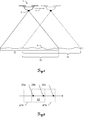
- Fig. 2 shows the trip points 20a-c defined by a flight plan and those at the trip points 20a-b each captured aerial images 21a-b.
- the triggering points 20a-c are set such that when the image is acquired, precisely at the respective points 20a-c a predetermined image overlap area 22 results for two consecutively acquired images 21a-b, this image overlap region 22, for example, having a screen area of 50% to 90%. the area of the aerial images 21a-b corresponds.
- Fig. 3 shows the principle of an inventive detection of two aerial images 21a-b in a flight movement of an inventive aircraft according to the direction represented by arrow 3 direction.
- the image 21a has been detected in flight of the UAV.
- the field of view of the camera shifts in such a way that an image 21b detected at a later time no longer has the identical detection area corresponding to the shifted position of the field of view, but partially overlaps the detection area of the images 21a-b, provided that second image 21b is still detected within the prescribed minimum overlap to be observed.
- an image triggering region 33 is defined for detecting the aerial images 21a-b.
- This image triggering area 33 is defined by a predetermined maximum overlap of the images 21a-b, eg 90% to 80% of the respective image area, and by a minimum overlap of the images 21a-b, eg 65% to 55% of the respective image area.
- the maximum overlap area 31 and the minimum overlap area 32 of the images 21a-b thus define a permissible relative offset of the images 21a-b or of the aircraft with which these images 21a-b are detected.
- the second image 21b is detected in the limits 23a with respect to the direction of flight (according to the flight plan) of the aircraft.
- the second image 21b is detected in the boundaries 23b with respect to the direction of movement of the aircraft.
- Image capturing is executable at any (time) point within these limits.
- the image triggering area 33 thus also defines a route section with regard to the direction of flight (flight route according to the flight plan) within which aerial photography can take place. According to the invention, aerial photography takes place while flying through this section of the route.
- the position of the image-triggering region 33 is further determined by the position of the triggering point for the first image 21a or by the position of the aircraft in the detection of the first image 21a.
- the image triggering range is dependent on the system depending on the current or specified in the context of flight planning altitude of the aircraft and the field of view of the camera.
- the image triggering region 33 or overlap region to be maintained prescribes a triggering time frame for aerial photography.
- the orientation of the aircraft or the camera ie the position of the aircraft in space, continuously determined and depending on the respective orientation while flying through the image triggering area 33, the detection of the aerial image triggered.
- a predetermined maximum angular deviation with respect to a predetermined target orientation eg nadir orientation 35
- a predetermined target orientation eg nadir orientation 35
- the nadir orientation 35 corresponds to the predetermined spatial orientation for the camera axis.
- the triggering of the aerial image acquisition is delayed if the angular deviation is too great when the image triggering area is reached (entry into the image triggering region during the flight movement).
- the delay is continued until the orientation of the aircraft 1 corresponds to the defined measurement criteria (permissible angular range with respect to the nadir orientation). If these measurement criteria are reached while flying through the image release area, the image capture is triggered.
- aerial images of an aerial image series can be acquired, each with a substantially parallel or the same orientation of the camera, whereby a significantly increased Accuracy is obtained for a generated stereo-terrain image and also the necessary image processing effort can be kept relatively low (as this is a significantly low number of images to process).
- a position of a subsequent trigger point or the image triggering area for this point for example, in a greatly delayed triggering of the image capture (eg triggering on reaching a minimum overlap for the images to be observed) are changed so that for the aerial image capture to this next trigger point a corresponding image triggering range (Overlap compliance for the following aerial photographs) is given.
- the respective following triggering point and the associated triggering range can be maintained in position, whereby, for example (in the case of again delayed triggering for the first triggering point), two directly successive aerial image captures take place.
- the aircraft's airspeed may be adjusted (reduced) to provide the time window for image acquisition to change (increase) and the probability of Achievement of the maximum angular deviation is increased.
- Such an adaptation of the airspeed can also take place as a function of other factors, eg for terrain sections to be detected with increased accuracy.
- a resulting gap in the aerial image series can be closed according to the invention in that the aircraft is specifically flown controlled again to the relevant trigger point (automatically) and the picture capturing according to the invention is repeated with respect to this trigger point.
- the resulting lift pattern can be inserted into the aerial photo series.
Landscapes
- Engineering & Computer Science (AREA)
- Physics & Mathematics (AREA)
- General Physics & Mathematics (AREA)
- Multimedia (AREA)
- Signal Processing (AREA)
- Aviation & Aerospace Engineering (AREA)
- Remote Sensing (AREA)
- Radar, Positioning & Navigation (AREA)
- Computer Vision & Pattern Recognition (AREA)
- Theoretical Computer Science (AREA)
- Studio Devices (AREA)
- Traffic Control Systems (AREA)
- Image Processing (AREA)
- Navigation (AREA)
- Aiming, Guidance, Guns With A Light Source, Armor, Camouflage, And Targets (AREA)
Abstract
Verfahren zur Luftbilderfassung mit einem unbemannten und steuerbaren Fluggerät mit Kamera, insbesondere Drohne, während einer Flugbewegung des Fluggeräts mit einem fortlaufenden Bestimmen einer Kameraposition und einer Ausrichtung einer optischen Kameraachse und einem Erfassen einer Luftbildsserie. Für jedes Luftbild (21a-b) der Luftbildserie wird das Erfassen des jeweiligen Luftbilds (21a-b) ausgelöst beim Durchfliegen eines jeweiligen Bildauslösebereichs (33) mit dem Fluggerät, wobei die Lage des jeweiligen Bildauslösebereichs (33) zumindest durch jeweils eine dem jeweiligen Bildauslösebereich (33) zugeordnete Auslöseposition in einem Flugplan bestimmt ist, und ausgelöst in Abhängigkeit von der Ausrichtung der Kameraachse beim Durchfliegen des jeweiligen Bildauslösebereichs (33) hinsichtlich einem Erfüllen einer definierten Maximal-Winkelabweichung bezüglich einer vorbestimmten Raumausrichtung.Method for aerial image acquisition with an unmanned and controllable aircraft with camera, in particular a drone, during flight movement of the aircraft with continuous determination of a camera position and alignment of an optical camera axis and acquisition of a series of aerial images. For each aerial image (21a-b) of the aerial image series, the acquisition of the respective aerial image (21a-b) is triggered when the aircraft flies through a respective image release area (33), the position of the respective image release area (33) at least by one of the respective image release areas (33) assigned trigger position is determined in a flight plan, and triggered as a function of the orientation of the camera axis when flying through the respective image trigger area (33) with regard to meeting a defined maximum angular deviation with respect to a predetermined spatial orientation.
Description
Die Erfindung betrifft ein Verfahren zur Erfassung von Luftbildern nach dem Oberbegriff des Anspruchs 1, eine Steuerungseinheit für einen unbemannten Luftbilderfassungsflug nach Anspruch 11 und ein unbemanntes Fluggerät nach Anspruch 13.The invention relates to a method for detecting aerial images according to the preamble of
Unbemannte Fluggeräte (UAV) nach dem Stand der Technik werden neben militärischen Einsatzgebieten zunehmend auch zur zivilen Geländeerfassung und Erdbeobachtung eingesetzt. Dabei wird gemäss einer Flugplanung eine vorbestimmte Flugroute befolgt, wobei mittels einer Kamera oder eines abbildenden Sensors eine Vielzahl von Luftbildern und Daten zumeist mit einer bestimmten Bilderfassungsfrequenz und einer bestimmten Bildüberlappung (benachbarter Bilder) entlang der Route erfasst wird. Hierfür sind typischerweise jeweilige Auslösepunkte für die Bilderfassung im Flugplan definiert. Zudem werden Positions- und Ausrichtungsdaten für das Fluggerät gemessen und mit den jeweils erfassten Bildern verknüpft. Die Bildauslösung wird beispielsweise basierend auf erfassten GPS-Positionsdaten oder Zeitdaten ausgelöst.Unmanned aerial vehicles (UAV) according to the prior art are increasingly used in addition to military applications for civilian terrain detection and Earth observation. In this case, according to a flight planning, a predetermined flight route is followed, wherein a plurality of aerial images and data is usually captured by a camera or an imaging sensor along the route with a specific image capture frequency and a certain image overlap (adjacent images). For this purpose, typically trigger points are defined for the image capture in the flight plan. In addition, position and orientation data for the aircraft are measured and linked to the captured images. The image triggering is triggered, for example, based on acquired GPS position data or time data.
Die Gesamtheit der während des Flugs erfassten Daten werden dann im Rahmen eines nachgeordneten "Post-Processings" derart verarbeitet, dass durch eine geeignete Verknüpfung der Bilder und Verrechnen der Lagedaten ein flächiges, stereophotogrammetrisches Abbild des erfassten Geländes und daraus ein orthogonales Produkt erzeugt wird.The totality of the data acquired during the flight is then processed as part of a subordinate "post-processing" such that a flat, stereophotogrammetric image of the detected terrain and an orthogonal product is generated by a suitable combination of images and calculation of the location data.
Insbesondere leichte UAVs sind dabei sehr windanfällig und instabil d.h. deren jeweilige Lage kann durch schon wenig starke Windböen oder andere äussere Einflüsse deutlich beeinflusst und in unbestimmter Weise verändert werden. Dadurch werden die Luftbilder jeweils nicht mit gleicher Ausrichtung bzw. Blickwinkel des Fluggeräts erfasst, sondern weisen jeweils einen Versatz nicht nur in Flugrichtung sondern z.B. auch in eine Richtung orthogonal zur Flugrichtung auf (Blickrichtung).In particular, light UAVs are very susceptible to wind and unstable, ie their position can be very little strong gusts of wind or other external influences are significantly influenced and altered indefinitely. As a result, the aerial images are not detected in each case with the same orientation or viewing angle of the aircraft, but each have an offset not only in the direction of flight but also, for example, in a direction orthogonal to the flight direction (line of sight).
Herkömmliche UAVs berücksichtigen bzw. korrigieren bei der Datenaufnahme und beim Auslösen der Bildaufnahme die räumliche Lage des Systems nicht derart aktiv, dass damit für die Bilderfassung eine einheitliche Blickrichtung garantiert werden könnte. Dies beeinträchtigt die Genauigkeit der postprozessierten Daten negativ, bis hin zu entstehenden Datenlücken, z.B. Bereiche des zu vermessenden Gebiets, die nicht bildmässig erfasst wurden. Durch die dabei erfassten Bilder mit unterschiedlichen Blickrichtungen verringert sich die Genauigkeit des daraus erzeugbaren Stereobildes, z.B. aufgrund perspektivischer Verzerrungen und verminderter Möglichkeit, Verknüpfungspunkte zwischen den Einzelbildern zu erzeugen. Diese sind für eine genaue Abgleichung der Stereobilder und einer Registrierung der Daten zueinander bei ungenauer GPS Bestimmung notwendig.Conventional UAVs do not take into account or correct the spatial position of the system during data acquisition and when triggering the image acquisition so actively that a uniform line of sight could be guaranteed for image acquisition. This adversely affects the accuracy of the post-processed data, even through resulting data gaps, e.g. Areas of the area to be surveyed that have not been photographically recorded. The images acquired in this case with different viewing directions reduce the accuracy of the stereo image that can be generated therefrom, e.g. due to perspective distortions and reduced possibility of creating nodes between the frames. These are necessary for an accurate matching of the stereo images and a registration of the data to each other in case of inaccurate GPS determination.
Wird das UAV durch eine Windböe erfasst und dadurch stark geneigt z.B. relativ zu einer Nadir- oder Horizontalausrichtung des UAVs so kann im Fall einer dabei erfolgten Luftbilderfassung nicht der gewünschte Geländebereich erfasst werden, sondern je nach Auslenkung des UAVs ein benachbarter oder gar ein Bereich, der keinen Überlapp mit zuvor erfassten Bildern aufweist.If the UAV is detected by a gust of wind and thereby greatly inclined, for example, relative to a nadir or horizontal alignment of the UAV so in the case of a completed aerial photography not the desired terrain area can be detected, but depending on the deflection of the UAVs an adjacent or even an area that has no overlap with previously acquired images.
Eine solche Datenlücke wird meist durch wiederholtes Überfliegen und erneutes Bilderfassen des betreffenden Gebiets geschlossen, wobei dies relativ zeitaufwändig ist.Such a data gap is usually closed by repeated flying over and re-capturing of the area in question, which is relatively time-consuming.
Aufgabe der vorliegenden Erfindung ist es, oben genannte Nachteile hinsichtlich Genauigkeit und Zeitaufwand bei der Luftbildaufnahme zu vermindern bzw. zu vermeiden.Object of the present invention is to reduce or avoid the above-mentioned disadvantages in terms of accuracy and time required for aerial photography.
Diese Aufgabe wird durch die Verwirklichung der kennzeichnenden Merkmale der unabhängigen Ansprüche gelöst. Merkmale, die die Erfindung in alternativer oder vorteilhafter Weise weiterbilden, sind den abhängigen Patentansprüchen zu entnehmen.This object is achieved by the realization of the characterizing features of the independent claims. Features which further develop the invention in an alternative or advantageous manner can be found in the dependent claims.
Die Erfindung betrifft ein Verfahren zur Luftbilderfassung mit einem unbemannten und steuerbaren Fluggerät mit Kamera, insbesondere Drohne, während einer Flugbewegung des Fluggeräts, mit einem fortlaufenden Bestimmen einer Kameraposition und einer Ausrichtung einer optischen Kameraachse und einem Erfassen einer Luftbildsserie. Für jedes Bild der Luftbildserie wird das Erfassen des jeweiligen Luftbilds beim Durchfliegen eines jeweiligen Bildauslösebereichs mit dem Fluggerät ausgelöst, wobei die Lage des jeweiligen Bildauslösebereichs zumindest durch jeweils eine dem jeweiligen Bildauslösebereich zugeordnete Auslöseposition in einem Flugplan bestimmt ist, und in Abhängigkeit von der Ausrichtung der optischen Kameraachse beim Durchfliegen des jeweiligen Bildauslösebereichs hinsichtlich eines Erfüllens einer definierten Maximal-Winkelabweichung bezüglich einer vorbestimmten Raumausrichtung (für die Kameraachse).The invention relates to a method for aerial imaging with an unmanned and controllable aircraft with camera, in particular drone, during a flight movement of the aircraft, with a continuous determination of a camera position and an alignment of an optical camera axis and detecting an aerial image series. For each image of the aerial image series, the detection of the respective aerial image is triggered when flying through a respective image triggering region with the aircraft, the position of the respective image triggering region being determined at least by a respective triggering position assigned to the respective image triggering region in a flight plan, and depending on the alignment of the optical Camera axis when flying through the respective image triggering area with respect to a fulfillment of a defined maximum angular deviation with respect to a predetermined spatial orientation (for the camera axis).
Das Durchfliegen des jeweiligen Bildauslösebereichs mit dem Fluggerät betrifft insbesondere die Position der Kamera (bzw. des Fluggeräts) bezüglich der Position des Bildauslösebereichs während der Flugbewegung. Solange die aktuell bestimmte Kameraposition (Fluggerätposition) innerhalb dieses Bildauslösebereichs liegt, findet das Durchfliegen dieses Bereichs statt.Flying through the respective image triggering area with the aircraft relates in particular to the position of the camera (or the aircraft) with respect to the position of the image release area during the flight movement. As long as the currently determined camera position (aircraft position) is within this image trigger area, flying through this area takes place.
Da ein unbemanntes Fluggerät (UAV) typischerweise verhältnismässig schwache Motoren aufweist, kann eine aktive Ausgleichung der Lage des UAVs nur bedingt oder nicht erfolgen. Mittels einer Inertialmesseinheit (IMU) oder anderen Positionsmesssensoren kann jedoch die Lage im Raum des UAVs und der am UAV vorgesehenen Kamera kontinuierlich bestimmt werden.Since an unmanned aerial vehicle (UAV) typically has comparatively weak engines, an active adjustment of the position of the UAV can only be limited or not possible. However, the position in the space of the UAV and the camera provided on the UAV can be continuously determined by means of an inertial measurement unit (IMU) or other position measuring sensors.
Das UAV fliegt gemäss dem Flugplan ein aufzunehmendes Gebiet ab. Dabei wird die Kamera innerhalb des vorbestimmten Zeitraums ausgelöst. Unter Hinzunahme der IMU-Messdaten ist dabei die Lage im Raum in "Echtzeit" ermittelbar. Sollte zum erstmöglichen Auslösezeitpunkt (innerhalb des Bildauslösebereichs) das UAV bzw. Kameraachse (Richtung der Bilderfassung mit der Kamera) von einer bevorzugten Ausrichtung abweichen (z.B. starke Schräglage anstelle von einer Nadir- oder horizontalen Blickrichtung der Kamera), dann wird der Auslösezeitpunkt um eine bestimmte Zeit verzögert.The UAV flies off according to the flight plan a recorded area. The camera is triggered within the predetermined period. By adding the IMU measurement data, the situation in the room can be determined in "real time". Should the UAV or camera axis (direction of image acquisition with the camera) deviate from a preferred orientation for the first possible triggering time (within the image triggering area) (eg strong tilt instead of nadir or horizontal viewing direction of the camera), the triggering time will be a certain one Time delayed.
Dadurch können maximal viele Luftbilder in gleicher Blickrichtung (z.B. Nadir) jedoch mit unterschiedlicher Position (mit definierter Mindestüberdeckung) erhalten werden.As a result, a maximum number of aerial images in the same direction (for example nadir) can be obtained with different positions (with a defined minimum coverage).
Insbesondere ist erfindungsgemäss der Bildauslösebereich durch einen vorgegebenen Überlappungsbereich für zwei während der Flugbewegung nacheinander zu erfassende Luftbilder definiert.In particular, according to the invention, the image release area is defined by a predetermined overlap area for two defined during the flight movement successively to be captured aerial photos.
In diesem Zusammenhang entspricht der Überlappungsbereich insbesondere erfindungsgemäss einer Bildfläche zwischen 50% und 90% des Luftbilds, insbesondere einer Bildfläche zwischen 60% und 80% des Luftbilds.In this context, according to the invention, the overlapping area corresponds in particular to an image area between 50% and 90% of the aerial image, in particular an image area between 60% and 80% of the aerial image.
Gemäss einer speziellen Ausführungsform der Erfindung ist der Bildauslösebereich derart bestimmt, dass ein bezüglich einer durch den Flugplan vorgegebenen Flugroute vorbestimmter Mindest-Bildüberlappungsbereich für die zwei nacheinander zu erfassenden Luftbilder definiert ist, insbesondere wobei der Mindest-Bildüberlappungsbereich beim Erfassen der zwei nacheinander zu erfassenden Luftbilder eingehalten wird.According to a special embodiment of the invention, the image triggering area is determined in such a way that a predetermined minimum image overlap area is defined for the two aerial images to be sequentially detected with respect to a flight route predetermined by the flight plan, in particular wherein the minimum image overlap area is adhered to when acquiring the two aerial images to be sequentially acquired becomes.
Insbesondere beträgt der Mindest-Bildüberlappungsbereich dabei erfindungsgemäss 60% der Bildfläche des Luftbilds.In particular, the minimum image overlap area according to the invention is 60% of the image area of the aerial image.
Bei einer Mindestüberlappung von 60 Prozent pro Stereo-Bild, kann bei der Flugplanung ein Sicherheitsfaktor von z.B. zusätzlichen 20 Prozent (insgesamt 80 Prozent Überlappung) der Bildfläche berücksichtigt und der Bildauslösebereich entsprechend definiert werden. Sollte dann eine Auslöseverzögerung nötig sein, kann die Verzögerung innerhalb der 20 Prozent Sicherheitsmarge (= Bildauslösebereich) zwischen Mindestüberlappung und Sicherheitsfaktor ausgenutzt werden.With a minimum overlap of 60 percent per stereo image, a safety factor of e.g. an additional 20 percent (80 percent overlap in total) of the image area is taken into account and the image release area is defined accordingly. If a tripping delay is necessary then the delay within the 20 percent safety margin (= image tripping range) between minimum overlap and safety factor can be exploited.
Bezüglich einer weiteren speziellen Ausführungsform der Erfindung sind für den jeweiligen Bildauslösebereich in Abhängigkeit von der zugeordneten Auslöseposition eine Startposition und eine Endposition definiert, insbesondere in Abhängigkeit von dem vorgegebenen Überlappungsbereich, insbesondere bezüglich der durch den Flugplan vorgegebenen Flugroute.With regard to a further specific embodiment of the invention, a starting position and an end position are defined for the respective image triggering region as a function of the assigned triggering position, in particular as a function of the predetermined overlapping region, in particular with regard to the flight route given by the flight plan.
D.h. sobald während der Flugbewegung die Grenzen des Sichtfelds für die Bilderfassung (deren aktuelle Positionen wiederum aus der fortlaufend bestimmten Kameraposition ableitbar sind) mit der Startposition des Bildauslösebereich übereinstimmen bis zum Erreichen einer Übereinstimmung des Sichtfeldgrenze mit der Endposition kann erfindungsgemäss ein Auslösen der Luftbilderfassung erfolgen. Diese Positionen können bestimmt sein durch Messvorgaben wie z.B. zulässige Überlappung der Bilder, Positionen der Auslösepunkte im Flugplan und/oder Solllage des Bildauslösebereichs relativ zum jeweiligen Auslösepunkt.That As soon as the limits of the field of view for the image acquisition (whose current positions can be derived from the continuously determined camera position) coincide with the start position of the image release area until the field of vision boundary coincides with the end position, the aerial image acquisition can be triggered according to the invention. These positions may be determined by measurement specifications such as e.g. permissible overlapping of the images, positions of the triggering points in the flight plan and / or desired position of the image triggering region relative to the respective triggering point.
Gemäss einer speziellen Ausführung der Erfindung ist die vorbestimmte Raumausrichtung eine Nadir-Ausrichtung oder eine horizontale Ausrichtung der Kameraachse. D.h. die Luftbilder werden innerhalb des zulässigen Winkelbereichs um die Nadir-Ausrichtung der Kamera oder um die horizontale Ausrichtung der Kamera erfasst.According to a specific embodiment of the invention, the predetermined spatial orientation is a nadir orientation or a horizontal orientation of the camera axis. That the aerial images are captured within the allowable angle range around the nadir orientation of the camera or the horizontal orientation of the camera.
Hinsichtlich der Flugplanung kann gemäss der Erfindung insbesondere der Flugplan eine Mehrzahl von Auslösepositionen definieren, wobei jede Auslöseposition eine Lage eines jeweils zugeordneten Bildauslösebereichs zur Erfassung eines jeweiligen Luftbilds definiert, insbesondere wobei die durch den Flugplan definierten Auslösepositionen mit dem Fluggerät gesteuert angeflogen werden, insbesondere gemäss einem vorgegebenen Flugmuster, insbesondere mäanderförmig.With regard to flight planning, according to the invention, in particular the flight plan can define a plurality of trigger positions, each trigger position defining a location of a respective assigned image trigger area for detecting a respective aerial image, in particular wherein the trigger positions defined by the flight plan are controlled by the aircraft, in particular according to one predetermined flight pattern, in particular meandering.
Gemäss einer speziellen Ausführungsform der Erfindung erfolgt ein Aktualisieren der nächsten Auslöseposition der Luftbildserie hinsichtlich deren Position im Flugplan in Abhängigkeit von einem tatsächlichen Erfassungszeitpunkt für die Luftbilderfassung und/oder von einer aktuellen, tatsächlichen Kameraposition bei der Luftbilderfassung. Damit kann eine dynamische Anpassung des Flugplans hinsichtlich der bereits erfassten und als nächste zu erfassende Gebietsteile erfolgen.According to a specific embodiment of the invention, the next triggering position of the aerial image series is updated with regard to its position in the flight plan as a function of an actual acquisition time for the aerial image acquisition and / or of a current, actual camera position in the aerial image acquisition. Thus, a dynamic adjustment of the flight plan with respect to the already recorded and next to be detected parts of the territory to take place.
Bezüglich eines Erreichens der definierten Maximal-Winkelabweichung bezüglich der vorbestimmten Raumausrichtung kann erfindungsgemäss insbesondere eine Fluggeschwindigkeit des Fluggeräts angepasst werden, insbesondere wobei durch ein Reduzieren der Fluggeschwindigkeit ein verfügbares Erfassungszeitfenster zur Luftbilderfassung vergrössert wird.With regard to reaching the defined maximum angular deviation with respect to the predetermined spatial orientation, according to the invention, in particular, an airspeed of the aircraft can be adjusted, in particular by increasing the airspeed an available acquisition time window for aerial image acquisition is increased.
Erfindungsgemäss kann insbesondere ausserdem in Abhängigkeit von dem Erfüllen der definierten Maximal-Winkelabweichung bezüglich der vorbestimmten Raumausrichtung während dem Durchfliegen des Bildauslösebereichs mit dem Fluggerät ein wiederholtes Anfliegen der dem Bildauslösebereich zugeordneten Auslöseposition und Erfassen des Luftbilds zu dieser Auslöseposition erfolgen.According to the invention, in addition, as a function of the fulfillment of the defined maximum angular deviation with respect to the predetermined spatial orientation while flying through the image triggering area with the aircraft, repeated approaching of the triggering position associated with the image triggering area and detection of the aerial image to this triggering position.
Des Weiteren kann im Rahmen der Erfindung die Maximal-Winkelabweichung bezüglich der vorbestimmten Raumausrichtung 5° betragen, insbesondere 2°.Furthermore, in the context of the invention, the maximum angular deviation with respect to the predetermined spatial orientation can be 5 °, in particular 2 °.
Die Erfindung betrifft ausserdem eine Steuerungseinheit für einen unbemannten Luftbilderfassungsflug, die ausgebildet ist zum Erhalt von Positionsinformation, von Ausrichtungsinformation und von Flugplandaten für ein unbemanntes Fluggerät. Ferner ist die Steuerungseinheit ausgebildet zur derartigen Erzeugung von Steuersignalen zur Steuerung einer Kamera des Fluggeräts für ein Luftbilderfassen, dass das Erfassen eines jeden Luftbilds einer Luftbildserie basierend auf den Steuersignalen gesteuert auslösbar ist
- bei einem Vorliegen einer aus der Positionsinformation ableitbaren Kameraposition innerhalb eines aus den Flugplandaten ableitbaren jeweiligen Bildauslösebereichs, wobei die Lage des jeweiligen Bildauslösebereichs zumindest durch jeweils eine dem jeweiligen Bildauslösebereich zugeordnete Auslöseposition gemäss der Flugplandaten bestimmt ist, und
- in Abhängigkeit von einer aus der Ausrichtungsinformation ableitbaren Ausrichtung einer optischen Kameraachse hinsichtlich eines Erfüllens einer definierten Maximal-Winkelabweichung bezüglich einer vorbestimmten Raumausrichtung (für die optische Kameraachse).
- in the presence of a camera position derivable from the position information within a respective image triggering region derivable from the flight plan data, wherein the position of the respective image triggering region is determined at least by a respective triggering position according to the flight plan data assigned to the respective image triggering region, and
- depending on an orientation of an optical camera axis derivable from the orientation information with regard to satisfying a defined maximum angular deviation with respect to a predetermined spatial orientation (for the optical camera axis).
Ferner betrifft die Erfindung ein System aus einer erfindungsgemässen Steuerungseinheit (gemäss obiger Ausführung), einer Kamera, einem Speicher und einer Sensoreinheit zur Bestimmung der Kameraposition und Ausrichtung der optischen Kameraachse, insbesondere GNSS-Empfangseinheit und Inertialmesseinheit. Die Positionsinformation und die Ausrichtungsinformation sind dabei durch die Sensoreinheit bestimmbar und bereitstellbar, die Flugplandaten vermittels des Speichers bereitstellbar und die Kamera mittels der durch die Steuerungseinheit erzeugbaren Steuersignale zur Luftbilderfassung ansteuerbar.Furthermore, the invention relates to a system comprising a control unit according to the invention (according to the above embodiment), a camera, a memory and a sensor unit for determining the camera position and alignment of the optical camera axis, in particular GNSS receiving unit and inertial measuring unit. The position information and the alignment information can be determined and made available by the sensor unit, the flight plan data can be made available by means of the memory and the camera can be activated by means of the control signals for aerial image capture that can be generated by the control unit.
Des Weiteren betrifft die Erfindung ein unbemanntes und steuerbares Fluggerät, insbesondere eine Drohne, mit einem obigen erfindungsgemässen System. Das Fluggerät verfügt über eine derartige Luftbilderfassungsfunktionalität, dass bei deren Ausführung gesteuert durch die Steuerungseinheit währende einer Flugbewegung des Fluggeräts ein Erfassen zumindest eines Luftbilds beim Durchfliegen eines Bildauslösebereichs mit dem Fluggerät, wobei die Lage des Bildauslösebereichs zumindest durch eine dem Bildauslösebereich zugeordnete Auslöseposition in einem Flugplan bestimmt ist, und in Abhängigkeit von der Ausrichtung der Kameraachse beim Durchfliegen des Bildauslösebereichs hinsichtlich einem Erfüllen einer definierten Maximal-Winkelabweichung bezüglich einer vorbestimmten Raumausrichtung (für die optische Achse der Kamera).Furthermore, the invention relates to an unmanned and controllable aircraft, in particular a drone, with an above inventive system. The aircraft has such an aerial imaging functionality that, when it is controlled by the control unit during a flight movement of the aircraft capture at least one aerial image when flying through an image triggering area with the aircraft, wherein the location of the image triggering area determined at least by a triggering position associated with the image triggering area in a flight plan and depending on the orientation of the camera axis as it travels through the image release area to meet a defined maximum angular deviation relative to a predetermined spatial orientation (for the camera's optical axis).
Gemäss einer speziellen Ausführungsform der Erfindung ist die Steuerungseinheit derart ausgebildet, dass mit dem Fluggerät ein erfindungsgemässes Verfahren nach einer der obigen Ausführungen ausführbar ist.According to a special embodiment of the invention, the control unit is designed in such a way that with the aircraft a method according to the invention according to one of the above explanations can be carried out.
Ferner betrifft die Erfindung ein Computerprogrammprodukt mit Programmcode, der auf einem maschinenlesbaren Träger gespeichert ist oder zumindest teilweise durch eine elektromagnetische Welle verkörpert ist, zum Erhalten von Positionsinformation, von Ausrichtungsinformation und von Flugplandaten für ein unbemanntes Fluggerät mit Kamera und zur Steuerung einer Luftbilderfassung in Abhängigkeit von der Positionsinformation, der Ausrichtungsinformation und den Flugplandaten, insbesondere in Abhängigkeit von einer Ausrichtung und Position der Kamera, insbesondere gemäss einem erfindungsgemässen Verfahren, insbesondere wenn das Programm auf einer als erfindungsgemässe Steuerungseinheit ausgebildeten elektronischen Datenverarbeitungseinheit ausgeführt wird.The invention further relates to a computer program product with program code stored on a machine-readable carrier or at least partially embodied by an electromagnetic wave, for obtaining position information, alignment information and flight plan data for an unmanned aerial vehicle with camera and for controlling an aerial image acquisition as a function of the position information, the orientation information and the flight plan data, in particular as a function of an orientation and position of the camera, in particular according to a method according to the invention, in particular if the program is on a control unit according to the invention trained electronic data processing unit is executed.
Das erfindungsgemässe Verfahren und die erfindungsgemässe Vorrichtung werden nachfolgend anhand von in den Zeichnungen schematisch dargestellten konkreten Ausführungsbeispielen rein beispielhaft näher beschrieben, wobei auch auf weitere Vorteile der Erfindung eingegangen wird. Im Einzelnen zeigen:
- Fig.1
- eine Erfassung von Luftbildern mit einem erfindungsgemässen unbemannten Fluggerät;
- Fig.2
- Auslösepunkte eines Flugplans und die an diesen jeweiligen Auslöspunkten erfindungsgemäss erfassten Geländebereichen ;
- Fig.3
- das Prinzip eines erfindungsgemässen Erfassens zweier überlappender Luftbilder; und
- Fig.4
- ein erfindungsgemässes Fluggerät und einen bezüglich der Ausrichtung des Fluggeräts zulässigen Winkelbereich α für das Erfassen eines Luftbilds.
- Fig.1
- a recording of aerial images with an inventive unmanned aerial vehicle;
- Fig.2
- Trigger points of a flight plan and the terrain areas detected according to the invention at these respective trigger points;
- Figure 3
- the principle of an inventive detection of two overlapping aerial images; and
- Figure 4
- an inventive aircraft and an allowable with respect to the orientation of the aircraft angle range α for detecting an aerial image.
Das Fluggerät 1 verfügt über eine Positionsbestimmungseinheit mittels derer fortlaufend die aktuelle Position des Fluggeräts 1 bzw. der Kamera 2 bestimmt wird. Diese Positionsbestimmungseinheit ist vorzugsweise ausgebildet als GNSS-Empfangseinheit (z.B. GPS, GLONASS oder Galileo), wobei GNSS-Positionssignale erfasst und basierend auf diesen Signalen eine Position des UAVs 1 abgeleitet wird. Zudem weist das UAV 1 eine inertiale Messeinheit (IMU) zur Bestimmung, insbesondere fortlaufend, einer aktuellen Ausrichtung des Fluggeräts 1 bzw. der Kamera 2 (also einer optischen Achse der Kamera) auf. Hierfür können beispielsweise ein Neigungssensor, ein Beschleunigungssensor, ein Magnetkompass und/oder ein Drehratensensor vorgesehen sein.The
Das Fluggerät 1 bewegt sich entlang einer vorgegebenen Route (symbolisiert durch den Pfeil 3). Dabei werden fortlaufend die Position und die Ausrichtung des Fluggeräts 1 (der Kamera 2) bestimmt. Erreicht das UAV 1 eine Position für das Erfassen eines nächsten Bildes, so wird ein Luftbild entsprechend dem nächsten Geländeabschnitt 12 erfasst. Dabei ergibt sich in Abhängigkeit der Fluggeschwindigkeit und des jeweiligen Bildauslösezeitpunkts ein Überlappungsbereich 13 für die Geländeabschnitte, d.h. ein Geländebereich 13 der durch beide Luftbilder erfasst ist.The
Gemäss der bestimmten Flugroute sind in Abhängigkeit des zu erfassenden Geländes 5 einzelne Auslöspunkte für das Erfassen von Luftbildern des Geländes 5 definiert, d.h. es sind Positionen für die zu erfassenden Luftbilder einer Luftbildserie bestimmt. Diese Punkte sind so vorgegeben, dass jeweils nacheinander erfasste Luftbilder jeweils einen bestimmten Bildüberlappungsbereich aufweisen. Beispielsweise sollen zwei benachbarte Luftbilder sich jeweils um mindestens 60% ihrer Bildfläche überschneiden. Dies erlaubt ein sicheres Erstellen eines Stereobildes des jeweiligen Geländeteils auf Basis dieser beiden Bilder.According to the determined flight route, 5 individual trigger points for the capture of aerial images of the
Für jeden dieser Auslösepunkte ist ein Bildauslösebereich definiert. Dieser ist erfindungsgemäss derart gewählt, dass ein Bilderfassen während eines Durchfliegens dieses Bildauslösebereichs (solange während der Flugbewegung die Position des Fluggeräts 1 bzw. der Kamera 2 innerhalb des Bildauslösebereichs vorliegt) das Einhalten des mindestens geforderten Mindest-Überlappungsbereichs gewährleistet.For each of these trigger points, an image trigger area is defined. This is selected according to the invention such that capturing the image during a flying through of this image triggering region (as long as the position of the
Ferner ist der Bildauslösebereich so gewählt, dass dadurch ein Sicherheitsbereich für das Bilderfassen gegeben ist, d.h. es ergibt sich ein Zeitfenster, in dem das Bilderfassen unter den vorgegebenen Messanforderungen ausgeführt werden kann. Beispielsweise ist für den Bildauslösebereich ein Startpunkt gesetzt, der einer 80-prozentigen Bildüberlappung (für zwei nacheinander zu erfassende Bilder) entspricht, und ein Endpunkt gesetzt, der einer 60-prozentigen Überlappung entspricht, wobei das Luftbild für den Auslösepunkt (der dem Bildauslösebereich zugeordnet ist) innerhalb dieser Grenzen zu erfassen ist. In Abhängigkeit der Fluggeschwindigkeit des Fluggeräts ergibt sich dabei das zulässige Zeitfenster für das Luftbilderfassen.Further, the image firing range is selected to provide a security area for image capturing, i. This results in a time window in which the image capture can be performed under the specified measurement requirements. For example, the image trigger area is set to a start point corresponding to an 80% image overlap (for two consecutive images) and an endpoint equal to a 60% overlap with the aerial image for the trigger point (associated with the image trigger area ) within these limits. Depending on the airspeed of the aircraft results in the allowable time window for aerial photography.
Innerhalb des Bildauslösebereichs bzw. des zulässigen Zeitfensters, d.h. beim Durchfliegen, wird das Bilderfassen für den betreffenden Auslösepunkt ausgelöst in Abhängigkeit davon, ob die Ausrichtung der optischen Achse der Kamera 2 (optische Kameraachse) innerhalb eines vorbestimmten Winkelbereichs um eine Nadir-Ausrichtung oder eine Horizontalausrichtung für die Kameraachse liegt. Diese Ausrichtung wird durch Bestimmen der Ausrichtung des UAVs 1 bzw. der Kamera 2 mittels der vorgesehenen IMU bestimmt.Within the image release area or the permissible time window, ie when flying through, the image capture for the relevant trigger point is triggered depending on whether the alignment of the optical axis of the camera 2 (optical camera axis) within a predetermined angular range by a nadir orientation or a Horizontal orientation for the camera axis is. This alignment is determined by determining the orientation of the
Mit anderen Worten heisst das, dass ein Luftbild für einen Auslösepunkt während einem Durchfliegen des zugehörigen Bildauslösebereichs erfasst wird, sobald bzw. falls die Kameraausrichtung eine Maximal-Winkelabweichung bezüglich einer vorbestimmten Soll-Raumrichtung (Nadir- oder Horizontalausrichtung) erfüllt.In other words, when the camera orientation satisfies a maximum angular deviation with respect to a predetermined target spatial direction (nadir or horizontal orientation), an aerial image for a trigger point is detected during flying through the associated image triggering area.
Dieses Verfahren basiert insbesondere darauf, dass die eigentliche Trajektorie für das UAV 1 vornehmlich durch Windstösse beeinträchtigt wird, das UAV 1 jedoch generell in eine horizontale Ausrichtung strebt. Diese automatisch erfolgende Bewegung wird durch eine "realtime" (kontinuierliche) Ausrichtungsmessung verfolgt. Bei einer bestimmten Abweichung von der Sollausrichtung um die Nadirausrichtung wird die Auslösung des Luftbilds bei Eintritt in den Bildauslösebereich verzögert und ggf. (bei Erfüllen der maximalen Sollwinkelabweichung) zu einem späteren Zeitpunkt innerhalb des sich ergebenden Zeitfensters vorgenommen.This method is based in particular on the fact that the actual trajectory for the
Damit ist gewährleistet, dass für eine Serie von Luftbildern ein maximales Mass an Aufnahmen gleicher bzw. paralleler Blickrichtungen generiert werden, die das nachfolgende "postprocessing" deutlich erleichtern (hinsichtlich Schnelligkeit und Rechenaufwand) und zudem die Genauigkeit für die daraus erzeugbaren Geländeabbildungen erhöhen.This ensures that a maximum amount of images of the same or parallel directions of view are generated for a series of aerial images that significantly facilitate the subsequent "postprocessing" (with regard to speed and computation effort) and also increase the accuracy for the terrain images that can be generated from them.
Zunächst ist das Bild 21a im Flug des UAVs erfasst worden. Während des Weiterflugs des UAVs verschiebt sich das Sichtfeld der Kamera derart, dass ein dann zu einem späteren Zeitpunkt erfasstes Bild 21b korrespondierend zu der verschobenen Lage des Sichtfelds nicht mehr den identischen Erfassungsbereich aufweist, sondern der Erfassungsbereich der Bilder 21a-b teilweise überlappt, sofern das zweite Bild 21b noch im Rahmen der vorgegebenen einzuhaltenden Mindestüberlappung erfasst wird.First, the
Erfindungsgemäss ist für das Erfassen der Luftbilder 21a-b ein Bildauslösebereich 33 definiert. Dieser Bildauslösebereich 33 wird definiert durch eine vorgegeben maximale Überlappung der Bilder 21a-b, z.B. 90% bis 80% der jeweiligen Bildfläche, und durch eine minimale Überlappung der Bilder 21a-b, z.B. 65% bis 55% der jeweiligen Bildfläche. Der maximale Überlappungsbereich 31 und der minimale Überlappungsbereich 32 der Bilder 21a-b definieren damit einen zulässigen relativen Versatz der Bilder 21a-b bzw. des Fluggeräts, mit dem diese Bilder 21a-b erfasst werden.According to the invention, an
Bei einer Bildauslösung bei Erreichen der maximalen Überlappung, d.h. bei einem Erreichen einer Position mit dem Fluggerät (der Kamera) derart, dass das zweite Bild mit einer derartigen Überlappung erfassbar ist, wird das zweite Bild 21b in den Grenzen 23a bezüglich der Bewegungsrichtung bzw. Flugroute (gemäss Flugplan) des Fluggeräts erfasst. Bei einer Bildauslösung bei Erreichen der minimalen Überlappung, wird das zweite Bild 21b in den Grenzen 23b bezüglich der Bewegungsrichtung des Fluggeräts erfasst. Das Bilderfassen ist zu jedem (Zeit-)Punkt innerhalb dieser Grenzen ausführbar.When the image is triggered when the maximum overlap is reached, i. upon reaching a position with the aircraft (the camera) such that the second image is detectable with such an overlap, the
Durch den Bildauslösebereich 33 ist damit ausserdem ein Streckenabschnitt bezüglich der Flugrichtung (Flugroute gemäss Flugplan) definiert, innerhalb dem das Luftbilderfassen erfolgen kann. Das Luftbilderfassen erfolgt damit erfindungsgemäss beim Durchfliegen dieses Streckenabschnitts.The
Die Lage des Bildauslösebereich 33 wird ferner durch die Position des Auslösepunkts für das erste Bild 21a bzw. durch die bei dem Erfassen des ersten Bilds 21a vorliegenden Position des Fluggeräts bestimmt.The position of the image-triggering
Ausserdem ist der Bildauslösebereich systembedingt abhängig von der aktuellen oder der im Rahmen der Flugplanung vorgegebenen Flughöhe des Fluggeräts und von dem Sichtfeld der Kamera.In addition, the image triggering range is dependent on the system depending on the current or specified in the context of flight planning altitude of the aircraft and the field of view of the camera.
Durch den einzuhaltenden Bildauslösebereich 33 bzw. Überlappungsbereich ist ein Auslösezeitrahmen für das Luftbilderfassen vorgegeben.The
Erfindungsgemäss wird zudem die Ausrichtung des Fluggeräts bzw. der Kamera, d.h. die Lage des Luftfahrzeugs im Raum, fortlaufend bestimmt und in Abhängigkeit der jeweiligen Ausrichtung während dem Durchfliegen des Bildauslösebereichs 33 das Erfassen des Luftbilds ausgelöst. Hierfür ist eine vorgegebene Maximal-Winkelabweichung bezüglich einer vorgegebenen Sollausrichtung (z.B. Nadir-Ausrichtung 35) (vgl.
Mit anderen Worten heisst das, dass das Auslösen der Luftbilderfassung bei einer zu grossen Winkelabweichung bei einem Erreichen des Bildauslösebereichs (Eintreten in den Bildauslösebereich während der Flugbewegung) verzögert wird. Die Verzögerung wird dabei derart lange fortgesetzt bis die Ausrichtung des Fluggeräts 1 den definierten Messkriterien (zulässiger Winkelbereich bezüglich der Nadir-Ausrichtung) entspricht. Werden diese Messkriterien während dem Durchfliegen des Bildauslösebereichs erreicht, so wird das Bilderfassen ausgelöst.In other words, the triggering of the aerial image acquisition is delayed if the angular deviation is too great when the image triggering area is reached (entry into the image triggering region during the flight movement). The delay is continued until the orientation of the
Dadurch können Luftbilder einer Luftbildserie mit jeweils im Wesentlichen paralleler bzw. gleicher Ausrichtung der Kamera erfasst werden, wodurch eine deutlich gesteigerte Genauigkeit für ein daraus erzeugtes Stereo-Geländebild erzielt wird und zudem der dafür notwendige Bildverarbeitungsaufwand vergleichsweise gering gehalten werden kann (da dadurch eine deutlich geringe Anzahl von Bilder zu verarbeiten ist).As a result, aerial images of an aerial image series can be acquired, each with a substantially parallel or the same orientation of the camera, whereby a significantly increased Accuracy is obtained for a generated stereo-terrain image and also the necessary image processing effort can be kept relatively low (as this is a significantly low number of images to process).
In Abhängigkeit des tatsächlichen Auslösezeitpunkt bzw. der tatsächlichen Position des Fuggeräts bei der Bilderfassung kann der Flugplan angepasst werden. Insbesondere kann eine Position eines nachfolgenden Auslösepunkt oder des Bildauslösebereichs für diesen Punkt beispielsweise bei einer stark verzögerten Auslösung der Bildaufnahme (z.B. Auslösung bei Erreichen einer einzuhaltenden MindestÜberlappung für die Bilder) so verändert werden, dass für die Luftbilderfassung zu diesem nächsten Auslösepunkt ein den Anforderungen entsprechender Bildauslösebereich (Einhaltung der Überlappung für die folgenden Luftbilder) gegeben ist.Depending on the actual triggering time or the actual position of the Fuggeräts in the image acquisition of the flight plan can be adjusted. In particular, a position of a subsequent trigger point or the image triggering area for this point, for example, in a greatly delayed triggering of the image capture (eg triggering on reaching a minimum overlap for the images to be observed) are changed so that for the aerial image capture to this next trigger point a corresponding image triggering range (Overlap compliance for the following aerial photographs) is given.
Alternativ dazu kann der jeweilige nachfolgende Auslösepunkt und der zugehörige Auslösebereich positionsmässig beibehalten werden, wodurch beispielsweise (bei wiederum verzögerter Auslösung für den ersten Auslösepunkt) zwei unmittelbar aufeinander folgende Luftbilderfassungen erfolgen.Alternatively, the respective following triggering point and the associated triggering range can be maintained in position, whereby, for example (in the case of again delayed triggering for the first triggering point), two directly successive aerial image captures take place.
Wird während des Durchfliegens des Bildauslösebereichs z.B. eine starke Schwenkung bezüglich der bestimmten Ausrichtung des Fluggeräts festgestellt, so dass die Maximal-Winkelabweichung voraussichtlich nicht innerhalb des Bildauslösebereichs erreicht werden kann, so kann die Fluggeschwindigkeit des Fluggeräts angepasst (verringert) werden, damit das Zeitfenster zur Bilderfassung damit verändert (vergrössert) wird und die Wahrscheinlichkeit zur Erreichung der Maximal-Winkelabweichung vergrössert wird. Eine solche Anpassung der Fluggeschwindigkeit kann auch in Abhängigkeit anderer Faktoren erfolgen, z.B. für mit einer gesteigerten Genauigkeit zu erfassende Geländeabschnitte.For example, if a large swing is detected in the particular orientation of the aircraft during flight of the image triggering area, so that the maximum angular deviation is unlikely to be achieved within the image triggering range, the aircraft's airspeed may be adjusted (reduced) to provide the time window for image acquisition to change (increase) and the probability of Achievement of the maximum angular deviation is increased. Such an adaptation of the airspeed can also take place as a function of other factors, eg for terrain sections to be detected with increased accuracy.
Bei einem Nicht-Erfüllen dieses Winkel-Kriteriums beim Durchfliegen des Bereichs, wird für den betreffenden Auslösepunkt insbesondere kein Luftbild erfasst und die Luftbilderfassung bei dem nächsten Auslösepunkt fortgesetzt. Eine dadurch entstehende Lücke in der Luftbildserie kann erfindungsgemäss dadurch geschlossen werden, dass das Fluggerät gezielt erneut zu dem betreffenden Auslösepunkt (automatisch) gesteuert geflogen wird und bezüglich diesem Auslösepunkt das erfindungsgemässe Bilderfassen wiederholt wird. Das dabei entstehende Liftbild kann in die Luftbildserie eingefügt werden.If this angle criterion is not met while flying through the area, in particular no aerial image is detected for the relevant trigger point and the aerial image acquisition is continued at the next trigger point. A resulting gap in the aerial image series can be closed according to the invention in that the aircraft is specifically flown controlled again to the relevant trigger point (automatically) and the picture capturing according to the invention is repeated with respect to this trigger point. The resulting lift pattern can be inserted into the aerial photo series.
Es versteht sich, dass die dargestellten Figuren nur mögliche Ausführungsbeispiele schematisch darstellen. Die verschiedenen Ansätze können erfindungsgemäss ebenso miteinander sowie mit Verfahren und Vorrichtungen zur Luftbilderfassung, unbemannten Fluggeräten, des Stands der Technik kombiniert werden.It is understood that the illustrated figures represent only possible embodiments schematically. The various approaches according to the invention can also be combined with each other as well as with methods and devices for aerial photography, unmanned aerial vehicles, the state of the art.
Claims (15)
für jedes Luftbild (21a-b) der Luftbildserie das Erfassen des jeweiligen Luftbilds (21a-b) ausgelöst wird
for each aerial image (21a-b) of the aerial image series, the detection of the respective aerial image (21a-b) is triggered
dadurch gekennzeichnet, dass
der Bildauslösebereich (33) durch einen vorgegebenen Überlappungsbereich (22,31,32) für zwei während der Flugbewegung nacheinander zu erfassende Luftbilder (21a-b) definiert ist, insbesondere wobei der Überlappungsbereich (22,31,32) einer Bildfläche zwischen 50% und 90% des Luftbilds (21a-b) entspricht, insbesondere einer Bildfläche zwischen 60% und 80% des Luftbilds (21a-b).Method according to claim 1,
characterized in that
the image triggering region (33) is defined by a predetermined overlapping region (22, 31, 32) for two aerial images (21a-b) to be successively detected during the flight movement, in particular wherein the overlapping area (22, 31, 32) corresponds to an image area between 50% and 90% of the aerial image (21a-b), in particular an image area between 60% and 80% of the aerial image (21a-b).
dadurch gekennzeichnet, dass
der Bildauslösebereich (33) derart bestimmt ist, dass ein bezüglich einer durch den Flugplan vorgegebenen Flugroute vorbestimmter Mindest-Bildüberlappungsbereich (32) für die zwei nacheinander zu erfassenden Luftbilder (21a-b) definiert ist, insbesondere wobei der Mindest-Bildüberlappungsbereich (32) beim Erfassen der zwei nacheinander zu erfassenden Luftbilder (21a-b) eingehalten wird.Method according to claim 2,
characterized in that
the image trigger area (33) is determined such that a predetermined minimum image overlap area (32) is defined for the two aerial images (21a-b) to be acquired sequentially with respect to a flight route predetermined by the flight plan, in particular wherein the minimum image overlap area (32) Detecting the two aerial images (21a-b) to be detected in succession is observed.
dadurch gekennzeichnet, dass
der Mindest-Bildüberlappungsbereich (32) 60% der Bildfläche des Luftbilds (21a-b) beträgt.Method according to claim 3,
characterized in that
the minimum image overlap area (32) is 60% of the image area of the aerial image (21a-b).
dadurch gekennzeichnet, dass
für den jeweiligen Bildauslösebereich (33) in Abhängigkeit von der zugeordneten Auslöseposition (20a-c) eine Startposition und eine Endposition definiert sind, insbesondere in Abhängigkeit von dem vorgegebenen Überlappungsbereich (22,31,32), insbesondere bezüglich der durch den Flugplan vorgegebenen Flugroute.Method according to one of claims 1 to 4,
characterized in that
a start position and an end position are defined for the respective image trigger region (33) as a function of the assigned trigger position (20a-c), in particular as a function of the predetermined overlap region (22, 31, 32), in particular with respect to the flight route predetermined by the flight plan.
dadurch gekennzeichnet, dass
die vorbestimmte Raumausrichtung eine Nadir-Ausrichtung (35) oder eine horizontale Ausrichtung der Kameraachse ist.Method according to one of claims 1 to 5,
characterized in that
the predetermined spatial orientation is a nadir orientation (35) or a horizontal orientation of the camera axis.
dadurch gekennzeichnet, dass
der Flugplan eine Mehrzahl von Auslösepositionen (20a-c) definiert, wobei jede Auslöseposition (20a-c) eine Lage eines jeweils zugeordneten Bildauslösebereichs (33) zur Erfassung eines jeweiligen Luftbilds (21a-b) definiert, insbesondere wobei die durch den Flugplan definierten Auslösepositionen (20a-c) mit dem Fluggerät (1) gesteuert angeflogen werden, insbesondere gemäss einem vorgegebenen Flugmuster, insbesondere mäanderförmig.Method according to one of claims 1 to 6,
characterized in that
the flight plan defines a plurality of trigger positions (20a-c), each trigger position (20a-c) defining a location of a respective associated image trigger area (33) for sensing a respective aerial image (21a-b), particularly where the trigger positions defined by the flight plan (20a-c) are flown controlled with the aircraft (1), in particular according to a predetermined flight pattern, in particular meandering.
dadurch gekennzeichnet, dass
ein Aktualisieren der nächsten Auslöseposition (20a-c) der Luftbildserie hinsichtlich deren Position im Flugplan erfolgt in Abhängigkeit von
characterized in that
updating of the next trigger position (20a-c) of the aerial image series with respect to its position in the flight plan is effected as a function of
dadurch gekennzeichnet, dass
zum Erreichen der definierten Maximal-Winkelabweichung (α) bezüglich der vorbestimmten Raumausrichtung (35) eine Fluggeschwindigkeit des Fluggeräts (1) angepasst wird, insbesondere wobei durch ein Reduzieren der Fluggeschwindigkeit ein verfügbares Erfassungszeitfenster zur Luftbilderfassung vergrössert wird.Method according to one of claims 1 to 8,
characterized in that
in order to achieve the defined maximum angular deviation (α) with respect to the predetermined spatial orientation (35), an airspeed of the aircraft (1) is adjusted, in particular wherein an airspeed is available by reducing the airspeed Acquisition time window for aerial photography is increased.
dadurch gekennzeichnet, dass
in Abhängigkeit von dem Erfüllen der definierten Maximal-Winkelabweichung (α) bezüglich der vorbestimmten Raumausrichtung (35) während dem Durchfliegen des Bildauslösebereichs (33) mit dem Fluggerät (1) ein wiederholtes Anfliegen der dem Bildauslösebereich (33) zugeordneten Auslöseposition (20a-c) und Erfassen des Luftbilds (21a-b) zu dieser Auslöseposition (20a-c) erfolgt, und/oder
die Maximal-Winkelabweichung (α) bezüglich der vorbestimmten Raumausrichtung 5° beträgt, insbesondere 2°.Method according to one of claims 1 to 9,
characterized in that
as a function of the fulfillment of the defined maximum angular deviation (α) with respect to the predetermined spatial orientation (35) while flying through the image triggering area (33) with the aircraft (1) a repeated approach of the triggering position (20a-c) associated with the image triggering area (33) and detecting the aerial image (21a-b) to this triggering position (20a-c), and / or
the maximum angular deviation (α) with respect to the predetermined spatial orientation is 5 °, in particular 2 °.
die Steuerungseinheit ausgebildet ist zur derartigen Erzeugung von Steuersignalen zur Steuerung einer Kamera (2) des Fluggeräts (1) für ein Luftbilderfassen, dass das Erfassen eines jeden Luftbilds (21a-b) einer Luftbildserie basierend auf den Steuersignalen gesteuert auslösbar ist
the control unit is designed for the generation of control signals for controlling a camera (2) of the aircraft (1) for aerial photography so that the detection of each aerial image (21a-b) of an aerial image series can be triggered in a controlled manner based on the control signals
gekennzeichnet durch
eine derartige Luftbilderfassungsfunktionalität, dass bei deren Ausführung gesteuert durch die Steuerungseinheit währende einer Flugbewegung des Fluggeräts (1) ein Erfassen zumindest eines Luftbilds (21a-b) ausgelöst wird
marked by
Such an aerial image capture functionality that, when executed by the control unit during a flight movement of the aircraft (1), initiates the detection of at least one aerial image (21a-b)
dadurch gekennzeichnet, dass
die Steuerungseinheit derart ausgebildet ist, dass mit dem Fluggerät (1) ein Verfahren nach einem der Ansprüche 1 bis 10 ausführbar ist.Aircraft (1) according to claim 13,
characterized in that
the control unit is designed such that with the aircraft (1) a method according to one of claims 1 to 10 is executable.
Priority Applications (6)
| Application Number | Priority Date | Filing Date | Title |
|---|---|---|---|
| EP20130162632 EP2787319A1 (en) | 2013-04-05 | 2013-04-05 | Control of an image triggering system for taking aerial photographs in nadir alignment for an unmanned aircraft |
| BR112015024489A BR112015024489A2 (en) | 2013-04-05 | 2014-04-03 | nadir alignment aerial capture firing control for an unmanned aircraft |
| EP14715581.6A EP2981786B1 (en) | 2013-04-05 | 2014-04-03 | Control of an image triggering system for taking aerial photographs in nadir alignment for an unmanned aircraft |
| PCT/EP2014/056715 WO2014161945A1 (en) | 2013-04-05 | 2014-04-03 | Control of image triggering for aerial image capturing in nadir alignment for an unmanned aircraft |
| CN201480017333.3A CN105121999B (en) | 2013-04-05 | 2014-04-03 | The image for the Aerial Images collection that nadir for UAV is aligned triggers control |
| US14/781,540 US10273000B2 (en) | 2013-04-05 | 2014-04-03 | Control of image triggering for aerial image capturing in nadir alignment for an unmanned aircraft |
Applications Claiming Priority (1)
| Application Number | Priority Date | Filing Date | Title |
|---|---|---|---|
| EP20130162632 EP2787319A1 (en) | 2013-04-05 | 2013-04-05 | Control of an image triggering system for taking aerial photographs in nadir alignment for an unmanned aircraft |
Publications (1)
| Publication Number | Publication Date |
|---|---|
| EP2787319A1 true EP2787319A1 (en) | 2014-10-08 |
Family
ID=48092720
Family Applications (2)
| Application Number | Title | Priority Date | Filing Date |
|---|---|---|---|
| EP20130162632 Withdrawn EP2787319A1 (en) | 2013-04-05 | 2013-04-05 | Control of an image triggering system for taking aerial photographs in nadir alignment for an unmanned aircraft |
| EP14715581.6A Active EP2981786B1 (en) | 2013-04-05 | 2014-04-03 | Control of an image triggering system for taking aerial photographs in nadir alignment for an unmanned aircraft |
Family Applications After (1)
| Application Number | Title | Priority Date | Filing Date |
|---|---|---|---|
| EP14715581.6A Active EP2981786B1 (en) | 2013-04-05 | 2014-04-03 | Control of an image triggering system for taking aerial photographs in nadir alignment for an unmanned aircraft |
Country Status (5)
| Country | Link |
|---|---|
| US (1) | US10273000B2 (en) |
| EP (2) | EP2787319A1 (en) |
| CN (1) | CN105121999B (en) |
| BR (1) | BR112015024489A2 (en) |
| WO (1) | WO2014161945A1 (en) |
Cited By (7)
| Publication number | Priority date | Publication date | Assignee | Title |
|---|---|---|---|---|
| WO2017105257A1 (en) * | 2015-12-14 | 2017-06-22 | Marcin Szender Msp | Method of remote simultaneous triggering of cameras and recording the position of central projections of photographs |
| EP3140984A4 (en) * | 2015-03-31 | 2017-08-02 | SZ DJI Technology Co., Ltd. | Systems and methods for regulating uav operations |
| US9792613B2 (en) | 2015-03-31 | 2017-10-17 | SZ DJI Technology Co., Ltd | Authentication systems and methods for generating flight regulations |
| WO2018108711A1 (en) * | 2016-12-13 | 2018-06-21 | Deutsches Zentrum für Luft- und Raumfahrt e.V. | Method and device for determining the leading edges of two overlapping image captures of a surface |
| WO2019061859A1 (en) * | 2017-09-28 | 2019-04-04 | 深圳市大疆创新科技有限公司 | Mobile platform, image capture path generation method, program, and recording medium |
| US11094202B2 (en) | 2015-03-31 | 2021-08-17 | SZ DJI Technology Co., Ltd. | Systems and methods for geo-fencing device communications |
| US11513029B2 (en) | 2016-04-25 | 2022-11-29 | Siemens Aktiengesellschaft | Moving flying object for scanning an object, and system for analyzing damage to the object |
Families Citing this family (14)
| Publication number | Priority date | Publication date | Assignee | Title |
|---|---|---|---|---|
| JP6599603B2 (en) * | 2014-04-18 | 2019-10-30 | 東芝ライフスタイル株式会社 | Autonomous vehicle |
| US10313638B1 (en) | 2015-06-12 | 2019-06-04 | Amazon Technologies, Inc. | Image creation using geo-fence data |
| US10322801B1 (en) | 2015-06-12 | 2019-06-18 | Amazon Technologies, Inc. | Unmanned aerial vehicle based surveillance as a service |
| CN105763815B (en) * | 2016-05-05 | 2019-05-21 | 昆山阳翎机器人科技有限公司 | A kind of picture pick-up device and its control method of adjust automatically shooting interval |
| JP6500849B2 (en) * | 2016-06-23 | 2019-04-17 | カシオ計算機株式会社 | Imaging device, imaging method and program |
| CN107152926B (en) * | 2016-07-18 | 2018-08-24 | 哈尔滨工业大学 | A kind of satellite quickly rotates super large breadth sweeping imaging method |
| US11430148B2 (en) * | 2016-12-28 | 2022-08-30 | Datalogic Ip Tech S.R.L. | Apparatus and method for pallet volume dimensioning through 3D vision capable unmanned aerial vehicles (UAV) |
| CN107172404A (en) * | 2017-07-20 | 2017-09-15 | 清华大学深圳研究生院 | A kind of unmanned plane image-pickup method and system |
| GB2560393B (en) | 2017-07-31 | 2019-01-30 | Matthew Russell Iain | Unmanned aerial vehicles |
| US10769466B2 (en) | 2018-02-20 | 2020-09-08 | International Business Machines Corporation | Precision aware drone-based object mapping based on spatial pattern recognition |
| JP6586602B1 (en) * | 2018-06-13 | 2019-10-09 | 株式会社プロドローン | Unmanned aerial vehicle |
| KR20210102889A (en) * | 2018-11-21 | 2021-08-20 | 광저우 엑스에어크래프트 테크놀로지 씨오 엘티디 | Planning method, apparatus, control terminal and storage medium of survey and mapping sample points |
| CN112729242A (en) * | 2019-10-29 | 2021-04-30 | 南京迈界遥感技术有限公司 | Unmanned aerial vehicle oblique photography method based on tilt angle sensor |
| CN117470199B (en) * | 2023-12-27 | 2024-03-15 | 天津云圣智能科技有限责任公司 | Swing photography control method and device, storage medium and electronic equipment |
Citations (3)
| Publication number | Priority date | Publication date | Assignee | Title |
|---|---|---|---|---|
| US20030048357A1 (en) * | 2001-08-29 | 2003-03-13 | Geovantage, Inc. | Digital imaging system for airborne applications |
| US20120120069A1 (en) * | 2009-05-18 | 2012-05-17 | Kodaira Associates Inc. | Image information output method |
| US20130076862A1 (en) * | 2011-09-28 | 2013-03-28 | Kabushiki Kaisha Topcon | Image Acquiring Device And Image Acquiring System |
Family Cites Families (16)
| Publication number | Priority date | Publication date | Assignee | Title |
|---|---|---|---|---|
| DE4332590C2 (en) * | 1993-09-24 | 1996-10-24 | Deutsche Forsch Luft Raumfahrt | Airborne SAR system for determining a terrain topography |
| US7424133B2 (en) * | 2002-11-08 | 2008-09-09 | Pictometry International Corporation | Method and apparatus for capturing, geolocating and measuring oblique images |
| FI117490B (en) * | 2004-03-15 | 2006-10-31 | Geodeettinen Laitos | Procedure for defining attributes for tree stocks using a laser scanner, image information and interpretation of individual trees |
| JP4488804B2 (en) | 2004-06-23 | 2010-06-23 | 株式会社トプコン | Stereo image association method and three-dimensional data creation apparatus |
| US7324687B2 (en) * | 2004-06-28 | 2008-01-29 | Microsoft Corporation | Color segmentation-based stereo 3D reconstruction system and process |
| DE102007015561B3 (en) * | 2007-03-29 | 2008-08-21 | Deutsches Zentrum für Luft- und Raumfahrt e.V. | Method for exploring ice area or dry area by radar echo-sounder sounding, involves investigating area by radar sensor or by multiple compatible radar sensors of same working wavelengths |
| US7991226B2 (en) * | 2007-10-12 | 2011-08-02 | Pictometry International Corporation | System and process for color-balancing a series of oblique images |
| US8531472B2 (en) * | 2007-12-03 | 2013-09-10 | Pictometry International Corp. | Systems and methods for rapid three-dimensional modeling with real façade texture |
| JP4970296B2 (en) * | 2008-01-21 | 2012-07-04 | 株式会社パスコ | Orthophoto image generation method and photographing apparatus |
| US8497905B2 (en) * | 2008-04-11 | 2013-07-30 | nearmap australia pty ltd. | Systems and methods of capturing large area images in detail including cascaded cameras and/or calibration features |
| US8155433B2 (en) * | 2008-07-10 | 2012-04-10 | Goodrich Corporation | Method of object location in airborne imagery using recursive quad space image processing |
| CN101976429B (en) | 2010-10-27 | 2012-11-14 | 南京大学 | Cruise image based imaging method of water-surface aerial view |
| US20130100307A1 (en) * | 2011-10-25 | 2013-04-25 | Nokia Corporation | Methods, apparatuses and computer program products for analyzing context-based media data for tagging and retrieval |
| US9977978B2 (en) * | 2011-11-14 | 2018-05-22 | San Diego State University Research Foundation | Image station matching, preprocessing, spatial registration and change detection with multi-temporal remotely-sensed imagery |
| IL217501A (en) * | 2012-01-12 | 2017-09-28 | Israel Aerospace Ind Ltd | System and method for maneuvering of an air vehicle |
| US9075415B2 (en) * | 2013-03-11 | 2015-07-07 | Airphrame, Inc. | Unmanned aerial vehicle and methods for controlling same |
-
2013
- 2013-04-05 EP EP20130162632 patent/EP2787319A1/en not_active Withdrawn
-
2014
- 2014-04-03 EP EP14715581.6A patent/EP2981786B1/en active Active
- 2014-04-03 US US14/781,540 patent/US10273000B2/en active Active
- 2014-04-03 WO PCT/EP2014/056715 patent/WO2014161945A1/en active Application Filing
- 2014-04-03 CN CN201480017333.3A patent/CN105121999B/en active Active
- 2014-04-03 BR BR112015024489A patent/BR112015024489A2/en active Search and Examination
Patent Citations (3)
| Publication number | Priority date | Publication date | Assignee | Title |
|---|---|---|---|---|
| US20030048357A1 (en) * | 2001-08-29 | 2003-03-13 | Geovantage, Inc. | Digital imaging system for airborne applications |
| US20120120069A1 (en) * | 2009-05-18 | 2012-05-17 | Kodaira Associates Inc. | Image information output method |
| US20130076862A1 (en) * | 2011-09-28 | 2013-03-28 | Kabushiki Kaisha Topcon | Image Acquiring Device And Image Acquiring System |
Cited By (18)
| Publication number | Priority date | Publication date | Assignee | Title |
|---|---|---|---|---|
| US11094202B2 (en) | 2015-03-31 | 2021-08-17 | SZ DJI Technology Co., Ltd. | Systems and methods for geo-fencing device communications |
| US9792613B2 (en) | 2015-03-31 | 2017-10-17 | SZ DJI Technology Co., Ltd | Authentication systems and methods for generating flight regulations |
| US11367081B2 (en) | 2015-03-31 | 2022-06-21 | SZ DJI Technology Co., Ltd. | Authentication systems and methods for generating flight regulations |
| US11120456B2 (en) | 2015-03-31 | 2021-09-14 | SZ DJI Technology Co., Ltd. | Authentication systems and methods for generating flight regulations |
| US9805607B2 (en) | 2015-03-31 | 2017-10-31 | SZ DJI Technology Co., Ltd. | Authentication systems and methods for generating flight regulations |
| CN107409174A (en) * | 2015-03-31 | 2017-11-28 | 深圳市大疆创新科技有限公司 | System and method for the operation of control unmanned vehicle |
| US9870566B2 (en) | 2015-03-31 | 2018-01-16 | SZ DJI Technology Co., Ltd | Authentication systems and methods for generating flight regulations |
| CN107409174B (en) * | 2015-03-31 | 2020-11-20 | 深圳市大疆创新科技有限公司 | System and method for regulating operation of an unmanned aerial vehicle |
| US11961093B2 (en) | 2015-03-31 | 2024-04-16 | SZ DJI Technology Co., Ltd. | Authentication systems and methods for generating flight regulations |
| EP3140984A4 (en) * | 2015-03-31 | 2017-08-02 | SZ DJI Technology Co., Ltd. | Systems and methods for regulating uav operations |
| US9805372B2 (en) | 2015-03-31 | 2017-10-31 | SZ DJI Technology Co., Ltd | Authentication systems and methods for generating flight regulations |
| WO2017105257A1 (en) * | 2015-12-14 | 2017-06-22 | Marcin Szender Msp | Method of remote simultaneous triggering of cameras and recording the position of central projections of photographs |
| US11513029B2 (en) | 2016-04-25 | 2022-11-29 | Siemens Aktiengesellschaft | Moving flying object for scanning an object, and system for analyzing damage to the object |
| WO2018108711A1 (en) * | 2016-12-13 | 2018-06-21 | Deutsches Zentrum für Luft- und Raumfahrt e.V. | Method and device for determining the leading edges of two overlapping image captures of a surface |
| US10551187B2 (en) | 2016-12-13 | 2020-02-04 | DEUTSCHES ZENTRUM FüR LUFT-UND RAUMFAHRT E.V. | Method and device for determining the leading edges of two overlapping image captures of a surface |
| CN109891188B (en) * | 2017-09-28 | 2022-03-04 | 深圳市大疆创新科技有限公司 | Mobile platform, imaging path generation method, program, and recording medium |
| CN109891188A (en) * | 2017-09-28 | 2019-06-14 | 深圳市大疆创新科技有限公司 | Mobile platform, camera paths generation method, program and recording medium |
| WO2019061859A1 (en) * | 2017-09-28 | 2019-04-04 | 深圳市大疆创新科技有限公司 | Mobile platform, image capture path generation method, program, and recording medium |
Also Published As
| Publication number | Publication date |
|---|---|
| CN105121999B (en) | 2017-11-14 |
| EP2981786B1 (en) | 2021-11-24 |
| WO2014161945A1 (en) | 2014-10-09 |
| CN105121999A (en) | 2015-12-02 |
| EP2981786A1 (en) | 2016-02-10 |
| US20160133019A1 (en) | 2016-05-12 |
| US10273000B2 (en) | 2019-04-30 |
| BR112015024489A2 (en) | 2017-07-18 |
Similar Documents
| Publication | Publication Date | Title |
|---|---|---|
| EP2981786B1 (en) | Control of an image triggering system for taking aerial photographs in nadir alignment for an unmanned aircraft | |
| EP3009794B1 (en) | Redundant determining of positional information for an automatic landing system | |
| EP2044573B1 (en) | Monitoring camera, method for calibrating the monitoring camera, and use of the monitoring camera | |
| DE60313319T2 (en) | AIR EDUCATION SYSTEM | |
| EP3596570B1 (en) | Method for determining a path along an object, system and method for automatic inspecting an object | |
| EP3066419B1 (en) | Method and system for producing a vector map | |
| DE60307911T2 (en) | A method of directing an aircraft during the final phase of the landing and associated apparatus | |
| EP2433092B1 (en) | Aerial picture camera system and method for correcting distortion in an aerial picture | |
| EP2060873B1 (en) | Method of supporting the inertial navigation of an aircraft | |
| DE202016007867U1 (en) | Control the line of sight angle of an image processing platform | |
| EP2387017B1 (en) | Method and device for generating traffic data from digital aerial image sequences | |
| EP2381208A1 (en) | Method for determining positional data of a target object in a reference system | |
| DE10258545B4 (en) | Method and system for stabilizing a translation motion size of a missile | |
| EP3435030A1 (en) | Method for creating a 3d model of an object | |
| WO2023083620A1 (en) | Testing the environment sensor system and/or environment perception of a vehicle | |
| DE102014117277B4 (en) | carrier system | |
| DE102019116006A1 (en) | METHOD AND DEVICE FOR DETECTING OBJECTS IN CAMERA DEADROOMS | |
| DE60305345T2 (en) | IMAGE PROCESSING DEVICE WITH DETECTION AND SELECTION OF LIGHT SOURCES | |
| EP2897102A1 (en) | Method for determining positional data of a target object in a reference system and method for guiding an aircraft, preferably in the form of a missile | |
| EP3556088B1 (en) | Method and device for determining intersections between two overlapping images of a surface | |
| DE102014108255A1 (en) | Georeferencing of image data | |
| DE102014115046A1 (en) | Method and assistance system for determining a flight parameter of a flying object in flight | |
| DE102016120196A1 (en) | Method and device for automatically determining position and / or movement-related status information of a vehicle | |
| DE3109702A1 (en) | Navigation referencing by means of a contour sensor with map comparison | |
| DE102022120476A1 (en) | Method and reconnaissance system for detecting an unauthorized entry of a third-party drone into a defined air area |
Legal Events
| Date | Code | Title | Description |
|---|---|---|---|
| PUAI | Public reference made under article 153(3) epc to a published international application that has entered the european phase |
Free format text: ORIGINAL CODE: 0009012 |
|
| 17P | Request for examination filed |
Effective date: 20130405 |
|
| AK | Designated contracting states |
Kind code of ref document: A1 Designated state(s): AL AT BE BG CH CY CZ DE DK EE ES FI FR GB GR HR HU IE IS IT LI LT LU LV MC MK MT NL NO PL PT RO RS SE SI SK SM TR |
|
| AX | Request for extension of the european patent |
Extension state: BA ME |
|
| STAA | Information on the status of an ep patent application or granted ep patent |
Free format text: STATUS: THE APPLICATION IS DEEMED TO BE WITHDRAWN |
|
| 18D | Application deemed to be withdrawn |
Effective date: 20150409 |