EP2781979B1 - Real-time monitoring of vehicle - Google Patents
Real-time monitoring of vehicle Download PDFInfo
- Publication number
- EP2781979B1 EP2781979B1 EP14154659.8A EP14154659A EP2781979B1 EP 2781979 B1 EP2781979 B1 EP 2781979B1 EP 14154659 A EP14154659 A EP 14154659A EP 2781979 B1 EP2781979 B1 EP 2781979B1
- Authority
- EP
- European Patent Office
- Prior art keywords
- jerks
- vehicle
- high intensity
- axis
- time
- Prior art date
- Legal status (The legal status is an assumption and is not a legal conclusion. Google has not performed a legal analysis and makes no representation as to the accuracy of the status listed.)
- Active
Links
- 238000012544 monitoring process Methods 0.000 title claims description 40
- 230000036461 convulsion Effects 0.000 claims description 133
- 238000000034 method Methods 0.000 claims description 30
- 230000015654 memory Effects 0.000 claims description 19
- 230000008859 change Effects 0.000 claims description 2
- 230000001133 acceleration Effects 0.000 claims 10
- 238000004590 computer program Methods 0.000 claims 3
- 230000003595 spectral effect Effects 0.000 claims 1
- 238000004393 prognosis Methods 0.000 description 14
- 238000012360 testing method Methods 0.000 description 11
- 238000012545 processing Methods 0.000 description 10
- 238000001514 detection method Methods 0.000 description 7
- 238000004891 communication Methods 0.000 description 5
- 230000006870 function Effects 0.000 description 5
- 230000003993 interaction Effects 0.000 description 4
- 238000012423 maintenance Methods 0.000 description 4
- 238000012546 transfer Methods 0.000 description 4
- 230000036541 health Effects 0.000 description 3
- 238000004088 simulation Methods 0.000 description 3
- 230000001413 cellular effect Effects 0.000 description 2
- 238000012986 modification Methods 0.000 description 2
- 230000004048 modification Effects 0.000 description 2
- 230000003287 optical effect Effects 0.000 description 2
- 230000003449 preventive effect Effects 0.000 description 2
- 230000008569 process Effects 0.000 description 2
- 238000005070 sampling Methods 0.000 description 2
- 230000003068 static effect Effects 0.000 description 2
- 239000013589 supplement Substances 0.000 description 2
- 230000006399 behavior Effects 0.000 description 1
- 230000005540 biological transmission Effects 0.000 description 1
- 230000015556 catabolic process Effects 0.000 description 1
- 230000003111 delayed effect Effects 0.000 description 1
- 230000001419 dependent effect Effects 0.000 description 1
- 238000003745 diagnosis Methods 0.000 description 1
- 230000000694 effects Effects 0.000 description 1
- 238000002474 experimental method Methods 0.000 description 1
- 230000004044 response Effects 0.000 description 1
- 238000001228 spectrum Methods 0.000 description 1
Images


Classifications
-
- G—PHYSICS
- G07—CHECKING-DEVICES
- G07C—TIME OR ATTENDANCE REGISTERS; REGISTERING OR INDICATING THE WORKING OF MACHINES; GENERATING RANDOM NUMBERS; VOTING OR LOTTERY APPARATUS; ARRANGEMENTS, SYSTEMS OR APPARATUS FOR CHECKING NOT PROVIDED FOR ELSEWHERE
- G07C5/00—Registering or indicating the working of vehicles
-
- G—PHYSICS
- G05—CONTROLLING; REGULATING
- G05B—CONTROL OR REGULATING SYSTEMS IN GENERAL; FUNCTIONAL ELEMENTS OF SUCH SYSTEMS; MONITORING OR TESTING ARRANGEMENTS FOR SUCH SYSTEMS OR ELEMENTS
- G05B23/00—Testing or monitoring of control systems or parts thereof
- G05B23/02—Electric testing or monitoring
- G05B23/0205—Electric testing or monitoring by means of a monitoring system capable of detecting and responding to faults
- G05B23/0218—Electric testing or monitoring by means of a monitoring system capable of detecting and responding to faults characterised by the fault detection method dealing with either existing or incipient faults
- G05B23/0224—Process history based detection method, e.g. whereby history implies the availability of large amounts of data
- G05B23/0227—Qualitative history assessment, whereby the type of data acted upon, e.g. waveforms, images or patterns, is not relevant, e.g. rule based assessment; if-then decisions
- G05B23/0235—Qualitative history assessment, whereby the type of data acted upon, e.g. waveforms, images or patterns, is not relevant, e.g. rule based assessment; if-then decisions based on a comparison with predetermined threshold or range, e.g. "classical methods", carried out during normal operation; threshold adaptation or choice; when or how to compare with the threshold
Landscapes
- Physics & Mathematics (AREA)
- General Physics & Mathematics (AREA)
- Engineering & Computer Science (AREA)
- Automation & Control Theory (AREA)
- Traffic Control Systems (AREA)
Description
- The present disclosure described herein, in general, relates to real-time vehicle health prognosis, and more particularly to real-time monitoring of vehicle health for prognosis using an accelerometer in a complex vehicle-road interaction environment.
- Road vehicles are primary mode of transport for a majority of the population around the world; the road vehicle includes private vehicles, fleet vehicles or public vehicles. Being the primary mode of transport the vehicles need to be reliable and road worthy, in order to ensure reliability, these vehicles are needed to be maintained and serviced at regular intervals. The use of electronic system like On-Board Diagnostic has made the maintenance of the vehicle easier; in fact the electronic systems help change the focus from break-down maintenance of the vehicle to preventive maintenance of the vehicle.
- With the focus shifting to preventive maintenance for the vehicle, several prognosis models were designed in the art that can capture the signals and information from the sensors in the vehicle. The prognosis models were further improved to capture the road conditions and driver behavior in order to develop a more comprehensive model for prognosis, the comprehensive model helped real-time prognosis of vehicle which can be customized for each user or owner. The analysis by the prognosis models on the signals and information captured can be performed at a remote server, wherein the information for the prognosis from vehicle is relayed to the remote server using the communication channels.
- However, since the prognosis models are heavily dependent on the signals and information, the information generated from the captured signals is large, large information packets are transferred to the remote server using the communication network. It has been observed that for real-time monitoring of vehicle entire data acquired from chassis vibration having high sampling rates like 40 Hertz (Hz) - 300 Hertz (Hz) is required. The transfer of such large packets of information unnecessarily burdens the communication channel and its resources. Further transfer of large packets of information leads to delay in processing of the information as transfer of large packets is time consuming. The delayed analysis of information in critical events is undesirable as the consequence can be more damaging.
US 2013/0006674 describes a system and method for determining vehicle operation data. - This summary is provided to introduce aspects related to systems and methods for real-time prognosis of vehicles and such aspects are further described below in the detailed description. This summary is not intended to identify essential features of the claimed subject matter nor is it intended for use in determining or limiting the scope of the claimed subject matter.
- In one implementation, a monitoring unit for real-time monitoring of a vehicle is disclosed. The vehicle comprises a 3-axis accelerometer installed, to capture signals from a vehicle chassis during a motion. The monitoring unit is coupled to the 3-axis accelerometer, wherein the monitoring unit receives a data from an On-Board Diagnostic (OBD), wherein the data received is associated with a plurality of jerks detected by the three-axis accelerometer coupled to the three-axis accelerometer. In another implementation the 3-axis accelerometer can be embedded in the OBD, or installed independently in the vehicle. An intensity of each jerk of the plurality of jerks is compared to a predefined jerk threshold, wherein high intensity jerks of the plurality of jerks having the intensity same or above the predefined threshold are captured. An elapsed time for the high intensity jerks can be determined and compared to a predefined time threshold, wherein the elapsed time is indicative of a time between an observation of the high intensity jerks and the time required for a feedback to a driver or a user. The monitoring unit can further determine whether an analysis on the high intensity jerks captured, based on the comparison of the elapsed time to the predefined time threshold, is to be performed at the vehicle or at a server located remotely., At the vehicle the analysis may be performed at atleast one of the OBD and the other modules installed in the vehicle..
- In another implementation, a method for real-time monitoring of a vehicle is disclosed. The method comprising capturing data associated with a plurality of jerks detected by a three-axis accelerometer, wherein the 3-axis accelerometer is embedded in the vehicle configured to capture signals from vehicle chassis. The method further comprises determining an intensity of each jerk of the plurality of jerks detected, wherein the intensity is determined for each jerk of the plurality of jerks is compared to a predefined jerk threshold and high intensity jerks from the plurality of jerks, having the intensity equal to or more than the predefined jerk threshold are captured. Further determining an elapsed time for high intensity jerks from the plurality of jerks captured, wherein the elapsed time is indicative of time between an observation of the jerk and a feedback sent to a user, wherein the elapsed time for high intensity jerks from the plurality of jerks captured is compared to a predefined time threshold. The method further comprises comparing the elapsed time for high intensity jerks from the captured jerk to a predefined time threshold. Determining whether an analysis on the high intensity jerks from the plurality of jerks, based on the comparison of the elapsed time to the predefined time threshold, is to be performed at the vehicle or at a server located remotely. At the vehicle the analysis may be performed at atleast one of the OBD and the other modules installed in the vehicle.
- The detailed description is described with reference to the accompanying figures. In the figures, the left-most digit(s) of a reference number identifies the figure in which the reference number first appears. The same numbers are used throughout the drawings to refer like features and components.
-
Figure 1 illustrates a system for real-time monitoring of vehicle, in accordance with an embodiment of the present subject matter. -
Figure 2 illustrates the system of theFigure 1 , in accordance with an embodiment of the present subject matter. -
Figure 3 is a flowchart illustrating a method for real-time monitoring of a vehicle, in accordance with an embodiment of the present subject matter. -
Figure 4 is a flowchart illustrating real-time monitoring of a vehicle, in accordance with an embodiment of the present subject matter - System and method for real-time monitoring of a vehicle in a road-vehicle interaction is disclosed. It may be understood that the real-time monitoring of vehicle relates to prognosis. The present subject matter enables a user or owner or driver of vehicle/s or any other person to monitor their vehicle/s real-time using optimum sensors to capture signals and reducing amount of data that may be transferred to a remote server for analysis. The present disclosure enables to capture events, occurring during vehicle-road interaction, with specific signatures for prognosis and reporting the event to the interested owner or driver of the vehicle or user subscribing to a service which may be offered by the system.
- Specifically, the system may enable prognosis of vehicle health based on the real-time monitoring. Signals and data are captured from various signal acquirers like OBD, 3-axis accelerometer and/or GPS, and received by a receiving module or detection tool, wherein the receiving module may be mounted in tandem with OBD or on an independent hardware comprising a processor and memory. The receiving module may capture signals and data pertaining to a jerk from chassis dynamics of the vehicle using the 3-axis accelerometer, wherein the 3-axis accelerometer can be mounted in a fixed orientation, in the OBD or independently or in GPS. The detection tool or receiving module may simultaneously capture data from the OBD, 3-axis accelerometer and GPS. The GPS according to present disclosure may enable location stamping on an event of interest based upon the signature of the signals or the data received for the event. The event can be defined in term of high intensity jerks captured: high intensity jerks captured can have intensity same or more than a predefined threshold. The intensity for the jerk is computed using standard signal and data processing techniques. The GPS and the 3-axis accelerometer can work in tandem or independently based upon their interaction with the detection tool or the receiving module. The captured signals or data by the OBD are associated with the high intensity jerks capture or the event.
- The detection tool can further be communicably connected to an identification tool set which can also be called as analytic module based on the function performed. The identification tool set can perform two functions; determine whether the event is critical and determine the probability of the event occurring again. The identification tool set after determining whether the event is critical or not, determines whether to perform the analysis on the signals at the vehicle end or at the server end. Determining where to perform analysis helps reduce the size of data sample and amount of data sent in packets to the server for the event can be optimized; it is estimated that real-time monitoring of the vehicles using chassis dynamics can require entire acquired data from the signals with high sampling rates like 40 Hertz (Hz) - 300 Hertz (Hz).
- The critical events can be defined by the objective for monitoring of the vehicle, simulating using a test harness. According to an embodiment of the present disclosure chassis dynamics like 'yaw', 'roll' and 'pitch' are monitored real-time for the critical events. The test harness can be a test automation engine that may be implemented by way of a recursive module. The input to the test harness may be a set of configuration parameters defining the state of the system like vehicle type, road type, vehicle speed, total mass, location, time. The configuration parameters of the test harness simulate the probability of anomaly detection for the given set of input parameters. The test harness may automates analytics process and achieve better sacrificing accuracy. To ensure greater accuracy, one may use historical data and other related contextual information that may be available.
- According to an embodiment the identification tool set may adopt an identification methodology wherein, the vertical vibration along the Z-axis may be capture by the accelerometer. The vibration may be converted into a windowed jerk i.e. jerks in a particular time window. The jerk captured may be caused by a plurality of events like road pothole, harsh driving and/or roll. Therefore to understand the exact cause of the jerk a 3 - axis accelerometer may be used to capture the vibration along the three axis of Cartesian coordinates. The probability of event occurrence may be computed based on a simulated model and corroborated by experiments. Raw-data in time domain is captured for the event using the accelerometer and may be converted into a frequency domain using relevant signal processing techniques, further a probability may be derived for occurrence for each event followed by obtaining a joint probability of all such events to deduce an overall probability of occurrence of the critical event. The present disclosure may cluster the joint probability for improved deduction of the critical event. According to an embodiment of the present invention for computation of a critical event occurrence, the system may compare the amplitude threshold and/or spectrum shift.
- While aspects of described system and method for real-time monitoring of the vehicle may be implemented in any number of different systems, environments, and/or configurations, the embodiments are described in the context of the following exemplary system.
- Referring now to
Figure 1 , for asystem 100, for real-time monitoring of a vehicle 116-1. Thevehicles 116 may be coupled to aremote server 102 through anetwork 106. A plurality of vehicles may be coupled to theserver 102 throughnetwork 106. Thevehicles 116 further comprises of amonitoring unit 108 coupled to a 3-axis accelerometer 110. The 3-axis accelerometer 110 is configured to capture signals from a chassis of thevehicles 116. The 3-axis accelerometer 110 can be installed in thevehicles 116. The signals captured by the 3-axis accelerometer 110 are processed into a jerk with a quantifiable intensity using standard signal processing techniques. - The
monitoring unit 108 may be further coupled to an On-Board diagnostic (OBD) 112, wherein the OBD is connected to plurality of sensors mounted in the vehicle. The plurality of sensors provides continuous feedback to the OBD pertaining to vehicle performance and other vehicular systems. Themonitoring unit 108 is further coupled to a global position system (GPS) 114, wherein the GPS may imprint a position stamp on the jerk. - In one implementation, the
network 106 may be a wireless network, a wired network or a combination thereof. Thenetwork 106 can be implemented as one of the different types of networks, such as intranet, local area network (LAN), wide area network (WAN), the Internet, and the like. Thenetwork 106 may either be a dedicated network or a shared network. The shared network represents an association of the different types of networks that use a variety of protocols, for example, Hypertext Transfer Protocol (HTTP), Transmission Control Protocol/Internet Protocol (TCP/IP), Wireless Application Protocol (WAP), and the like, to communicate with one another. Further thenetwork 106 may include a variety of network devices, including routers, bridges, servers, computing devices, storage devices, and the like. - Referring now to
Figure 2 , thevehicles 116 is illustrated in accordance with an embodiment of the present subject matter. In one embodiment, thevehicles 116 may include amonitoring unit 108, anaccelerometer 110, anOBD 112, and aGPS 114. Themonitoring unit 108 comprises at least oneprocessor 208, an input/output (I/O)interface 210, and amemory 212. The at least oneprocessor 208 may be implemented as one or more microprocessors, microcomputers, microcontrollers, digital signal processors, central processing units, state machines, logic circuitries, and/or any devices that manipulate signals based on operational instructions. Among other capabilities, the at least oneprocessor 208 is configured to fetch and execute computer-readable instructions stored in thememory 212. - The I/
O interface 210 may include a variety of software and hardware interfaces, for example, a web interface, a graphical user interface, and the like. The I/O interface 210 may allow themonitoring unit 108 to interact with anaccelerometer 110, theGPS 114 and/orOBD 112. The I/O interface 210, may further enable themonitoring unit 108 to communicate toserver 102 or other computing devices, such as web servers and external data servers (not shown) throughnetwork 106. The I/O interface 210 can facilitate multiple communications within a wide variety of networks and protocol types, including wired networks, for example, LAN, cable, etc., and wireless networks, such as WLAN, cellular, or satellite. The I/O interface 210 may include one or more ports for connecting a number of devices to one another or to another server. - The
memory 212 may include any computer-readable medium known in the art including, for example, volatile memory, such as static random access memory (SRAM) and dynamic random access memory (DRAM), and/or non-volatile memory, such as read only memory (ROM), erasable programmable ROM, flash memories, hard disks, optical disks, and magnetic tapes. The memory 206 may includemodules 214 anddata 222. - The
modules 214 include routines, programs, objects, components, data structures, etc., which perform particular tasks or implement particular abstract data types. In one implementation, themodules 214 may include areceiving module 216, ananalytics module 218, andother modules 220. Theother modules 220 may include programs or coded instructions that supplement applications and functions of themonitoring unit 108. The receivingmodule 216 andanalytics module 218 may perform the same function of the detection tool and identification tool set respectively. - The
data 222, amongst other things, serves as a repository for storing data processed, received, and generated by one or more of themodules 214. Thedata 222 may also include aJerk threshold database 222, atime threshold database 226 andother data 228. Theother data 228 may include data generated as a result of the execution of one or more modules in theother module 220. - In one embodiment, a 3-
axis accelerometer 110 captures a signal pertaining to chassis dynamics of thevehicles 116. The signal captured by the 3-axis accelerometer 110 for chassis dynamics of thevehicles 116 is at least on one of an X-axis, a Y-axis, and a Z-axis of a Cartesian Co-ordinate system. The receivingmodule 216 receives the signal captured by the 3-axis accelerometer 110 and may convert the signal into a plurality jerks detected having an intensity using standard signal processing technique known in the art. Theanalytics module 218 receives the plurality of jerks and compares the intensity of each of the jerk to a predefined jerk threshold stored in thejerk threshold database 224. Theanalytics module 218 may capture high intensity jerks from the plurality of jerks, wherein the high intensity jerks have intensity equal to or more than the threshold. For each of the high intensity jerks, theanalytics module 218 determines elapsed time. The elapsed time is indicative of a time between an observation of the high intensity jerks and time required for a feedback to a driver or a user. The elapsed time according to an embodiment of the disclosure is captured at a preset delay enabling the comparing of the elapsed time to predefined time threshold stored and retrieved from thetime threshold database 226. - The
analytics module 218, further determines a location to perform or execute analytics on the high intensity jerks captured based upon the elapsed time. The location for performing the analysis may be at thevehicles 116 or at a server located remotely. The analysis may be performed at the location selected from the OBD, orother module 220 embedded in theprocessor 208. For example, in an emergency scenario when a very quick response is required, analysis can be performed in the OBD, in order to reduce latency of detection and alert; whereas other scenarios like driving pattern assessment, where feedback is tolerant of time intervals, forsay 1 hour, a major part of the analysis can be performed in the server. Further theanalytics module 218, is configured to receive an position stamp for the high intensity jerks, from theGPS 114. - The
analytics module 218 is further configured to receive signals and data from theOBD 112. The signals received from the OBD may relate to the vehicle performance or vehicle system. The signals from the OBD are captured in real-time and may be stored. The data received from the OBD, may be stored to perform analysis in order to understand the exact nature and/or cause for the high intensity jerks. Understanding the nature of the high intensity jerk helps understand the effects on the prognosis and diagnosis of the vehicle. - Referring to
Figure 2 , aserver 102 is illustrated in accordance with an embodiment of the present subject matter. In one embodiment, theserver 102 may include atleast server processor 230, server input/output (I/O)interface 232, andserver memory 234. The at least oneserver processor 230 may be implemented as one or more microprocessors, microcomputers, microcontrollers, digital signal processors, central processing units, state machines, logic circuitries, and/or any devices that manipulate signals based on operational instructions. Among other capabilities, the at least oneserver processor 230 is configured to fetch and execute computer-readable instructions stored in theserver memory 234. - The server I/
O interface 232 may include a variety of software and hardware interfaces, for example, a web interface, a graphical user interface, and the like. The server I/O interface 232 may further enable theserver 102 to communicate to thevehicles 116 or other devices, such as web servers and external data servers (not shown) throughnetwork 106. The server I/O interface 232 can facilitate multiple communications within a wide variety of networks and protocol types, including wired networks, for example, LAN, cable, etc., and wireless networks, such as WLAN, cellular, or satellite. The server I/O interface 232 may include one or more ports for connecting a number of devices to one another or to another server. - The
server memory 234 may include any computer-readable medium known in the art including, for example, volatile memory, such as static random access memory (SRAM) and dynamic random access memory (DRAM), and/or non-volatile memory, such as read only memory (ROM), erasable programmable ROM, flash memories, hard disks, optical disks, and magnetic tapes. Theserver memory 234 may includeserver modules 236 andserver data 242. - The
server modules 236 include routines, programs, objects, components, data structures, etc., which perform particular tasks or implement particular abstract data types. In one implementation, theserver modules 236 may include a test harness module 238, andother server modules 240. Theother server modules 240 may include programs or coded instructions that supplement applications and functions of theserver 102. - The
server data 242, amongst other things, serves as a repository for storing data processed, received, and generated by one or more of theserver modules 236. Theserver data 242 may also includeother server database 244. Theother server database 244 may include data generated as a result of the execution of one or more modules in theother server module 240. - The test harness module 238 receives the high intensity jerks captured and data associated with the high intensity jerks from the
vehicles 116 via thenetwork 106. The test harness module 238, analyzes the data received and the high intensity jerks. The test harness module 238 using a simulation model deduces the exact cause for the high intensity jerks and nature of the high intensity jerks. The simulation model comprises a set of historical data collected and stored inother database 244, wherein the set of historical data is collected over a preset time period. The simulation model may further be corroborated by experimentation data. The test harness module 238, further determines the probability for re-occurrence of the high intensity jerks. The probability is based on a probabilistic model, wherein the probabilistic model may comprise of the historical data and other contextual data captured from a plurality of sources. The plurality of sources can be a plurality of vehicle coupled to the server. - Referring now to
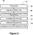
Figure 3 , a flowchart illustrating a method for real-time monitoring of a vehicle, in accordance with an embodiment of the present subject matter. The order in which themethod 300 is described is not intended to be construed as a limitation, and any number of the described method blocks can be combined in any order to implement themethod 300 or alternate methods. Additionally, individual blocks may be deleted from themethod 300 without departing from the spirit and scope of the subject matter described herein. Furthermore, the method can be implemented in any suitable hardware, software, firmware, or combination thereof. However, for ease of explanation, in the embodiments described below, themethod 300 may be considered to be implemented in the above describedvehicle monitoring unit 108. - At
block 302, a plurality of signals is captured by a 3-axis accelerometer 110 pertaining to chassis dynamics of a vehicle. The captured plurality of signals is received by a receivingmodule 218, wherein the receivingmodule 218 converts the plurality of signals received into a plurality of jerks detected having intensity. To convert the signal into the jerk detected standard signal processing techniques may be employed. - At
block 304, the intensity for each of the jerk of the plurality of the jerk is compared to a predefined jerk threshold by ananalytic module 218. Atblock 306, high intensity jerks is captured, wherein the high intensity jerks have intensity same or above the predefined jerk threshold. Atblock 308 the time elapsed for the high intensity jerks is determined. The elapsed time indicates the time taken when the high intensity jerks is detected till the time required to provide a feedback to the driver or the user. The elapsed time is compared to elapsed time threshold atBlock 310. Atblock 312 the high intensity jerks captured is mapped with corresponding elapsed time and a location is determined for further analysis of the captured data. The location for further analysis can be the vehicle or a server. - Referring now to
Figure 4 , a flowchart illustrating real-time monitoring of a vehicle, in accordance with an embodiment of the present subject matter. Theflow chart 400 illustrates an exemplary process flow enabling a monitoring unit to monitor the vehicle real-time. AtBlock 402, a plurality of jerks, experienced by the vehicle due to chassis dynamics, are detected by a three axis accelerometer. Data associated with the plurality of jerks detected may also be captured at theBlock 404. The data associated can be captured from various data and signal acquirers like On-Board Diagnostic system, a GPS, or an Electronic Control Unit (ECU) or a combination thereof. In the next step of theflow chart 400 atBlock 406, intensity for each jerk of the plurality of jerk is determined by standard data and signal processing techniques. The intensity determined for each of the plurality of jerks and is compared to a jerk threshold atBlock 408, wherein high intensity jerks having intensity more than or equal to the jerk threshold are captured atblock 410. - At
Block 412, an elapsed time is determined for the high intensity jerks captured in theBlock 410. AtBlock 414, the elapsed time for the high intensity jerks is compared to time threshold, wherein the high intensity jerks having elapse time less than or equal to the time threshold proceed to Block 416 or else they proceed to Block 420. The time threshold may depend upon parameters defined by a user or the driver or both. Comparing of the elapse time with time threshold enables a monitoring unit to decide whether to perform analytics, on the high intensity jerks captured, at the vehicle or at a server located remotely or both i.e. partially at the vehicle and partially at server. AtBlock 416 the analytics can be performed locally in the vehicle, wherein the OBD or any other device capable of processing installed in the vehicle performs the computation or analytics. The data captured and associated with the high intensity jerks may be used for analytics. The data associated may be captured real-time or can be retrieved from historical data. AtBlock 418, a feedback based on the analytics performed is sent to the driver or user. - At
Block 420, the high intensity jerks captured having elapse time greater than time threshold is received at the remote server. The data associated with the high intensity jerks may also be received, wherein the further analytics are performed and exact nature for the high intensity jerks is determined at theBlock 422. AtBlock 424, a feedback based on the analytics is sent to the driver or user or participating vehicle or combination thereof. - The written description describes the subject matter herein to enable any person skilled in the art to make and use the embodiments of the invention. The scope of the subject matter embodiments are defined by the claims and may include other modifications that occur to those skilled in the art. Such other modifications are intended to be within the scope of the claims if they have similar elements that do not differ from the literal language of the claims or if they include equivalent elements with insubstantial differences from the literal language of the claims.
Claims (8)
- A monitoring unit (108) for real-time monitoring of a vehicle, the monitoring unit (108) comprising:a processor (208); anda memory (212) coupled to the processor (208), wherein the memory (212) comprises a plurality of modules (214) capable of being executed by the processor (208), and wherein the plurality of modules (214) comprises:a receiving module (216) configured to receive data from an On-Board Diagnostic, (OBD) (112), wherein the data is associated with a plurality of jerks detected by a three-axis accelerometer (110) coupled to the OBD (112), wherein the three-axis accelerometer (110) is configured to capture chassis dynamics of the vehicle on at least one of an X-axis, a Y-axis, and a Z-axis of a Cartesian Coordinate system; andan analytics module (218) configured tocompare an intensity of each jerk of the plurality of jerks to a predefined jerk threshold;capture high intensity jerks of the plurality of jerks, wherein the high intensity jerks have intensity equal to or more than the predefined jerk threshold;determine an elapsed time for each of the high intensity jerks, wherein the elapsed time indicates time taken when the high intensity jerks are detected till the time required to provide a feedback to a user;compare the elapsed time for each of the high intensity jerks to a predefined time threshold; anddetermine whether an analysis on the high intensity jerks, based on the comparison of the elapsed time to the predefined time threshold, is to be performed at the vehicle or at a server (102) located remotely or partially at the vehicle and partially at the server (102), wherein the high intensity jerks having elapsed time less than or equal to the predefined time threshold are analyzed locally.
- The monitoring unit (108) of claim 1, wherein the data comprise at least one of the intensity of each jerk of the plurality of jerks, a ratio of jerk to acceleration of the vehicle, a ratio of acceleration of the vehicle to velocity of the vehicle, a power spectral density, a wavelet transform, a ratio of x-axis acceleration to y-axis acceleration, ratio of x-axis acceleration to z-axis acceleration followed by jerk computation, a ratio of z-axis acceleration to y-axis acceleration followed by jerk computation, a dominant frequency estimation on the ratio of x-axis acceleration to y-axis acceleration, and identifying change in loaded natural frequency of the vehicle.
- The monitoring unit (108) of any of the preceding claims, wherein the analytics module is further configured to receive a position stamp of the vehicle for the high intensity jerks from a Global Positioning System (GPS) unit (114).
- The monitoring unit (108) of any of the preceding claims, wherein the OBD (112) installed in the vehicle is adapted to perform the analysis of the high intensity jerks.
- A method for real-time monitoring of a vehicle, the method comprising:receiving data associated with a plurality of jerks detected by a three-axis accelerometer (110), wherein the 3-axis accelerometer (110) is embedded in the vehicle configured to capture signals from vehicle chassis on at least one of an X-axis, a Y-axis, and a Z-axis of a Cartesian Coordinate system;comparing an intensity of each jerk of the plurality of jerks to a predefined jerk threshold;capturing high intensity jerks of the plurality of jerks, wherein the high intensity jerks have intensity equal to or more than the predefined jerk threshold;determining an elapsed time for each of the high intensity jerks,wherein the elapsed time indicates time taken when the high intensity jerks are detected till the time required to provide a feedback to a user;comparing the elapsed time for each of the high intensity jerks to a predefined time threshold; anddetermining whether an analysis on the high intensity jerks, based on the comparison of the elapsed time to the predefined time threshold, is to be performed at the vehicle or at a server (102) located remotely or partially at the vehicle and partially at the server (102), wherein the high intensity jerks having elapsed time less than or equal to the predefined time threshold are analyzed locally, wherein at least one of the receiving, the comparing of the intensity, the capturing, the determining of elapsed time, the comparing of the elapsed time, and the determining is performed by a processor (208).
- The method of claim 5, further comprising receiving a position stamp of the vehicle for the high intensity jerks from a Global Positioning System (GPS).
- The method of claim 5 or 6, wherein the data is received from an On-Board Diagnostic (OBD).
- A computer program product having embodied thereon a computer program for real-time monitoring of a vehicle, the computer program product comprising:a program code for receiving data associated with a plurality of jerks detected by a three-axis accelerometer (110), wherein the 3-axis accelerometer (110) is embedded in the vehicle configured to capture signals from vehicle chassis on at least one of an X-axis, a Y-axis, and a Z-axis of a Cartesian Coordinate system;a program code for comparing an intensity of each jerk of the plurality of jerks to a predefined jerk threshold;a program code for capturing high intensity jerks of the plurality of jerks, wherein the high intensity jerks have intensity equal to or more than the predefined jerk threshold;a program code for determining an elapsed time for each of the high intensity jerks, wherein the elapsed time indicates time taken when the high intensity jerks are detected till the time required to provide a feedback to a user;a program code for comparing the elapsed time for each of the high intensity jerks to a predefined time threshold; anda program code for determining whether an analysis on the high intensity jerks, based on the comparison of the elapsed time to the predefined time threshold, is to be performed at the vehicle or at a server (102) located remotely or partially at the vehicle and partially at the server (102), wherein the high intensity jerks having elapsed time less than or equal to the predefined time threshold are analyzed locally.
Applications Claiming Priority (1)
| Application Number | Priority Date | Filing Date | Title |
|---|---|---|---|
| IN897MU2013 IN2013MU00897A (en) | 2013-03-20 | 2013-03-20 |
Publications (2)
| Publication Number | Publication Date |
|---|---|
| EP2781979A1 EP2781979A1 (en) | 2014-09-24 |
| EP2781979B1 true EP2781979B1 (en) | 2017-06-07 |
Family
ID=50101730
Family Applications (1)
| Application Number | Title | Priority Date | Filing Date |
|---|---|---|---|
| EP14154659.8A Active EP2781979B1 (en) | 2013-03-20 | 2014-02-11 | Real-time monitoring of vehicle |
Country Status (4)
| Country | Link |
|---|---|
| US (1) | US9324192B2 (en) |
| EP (1) | EP2781979B1 (en) |
| DK (1) | DK2781979T3 (en) |
| IN (1) | IN2013MU00897A (en) |
Families Citing this family (13)
| Publication number | Priority date | Publication date | Assignee | Title |
|---|---|---|---|---|
| US10656280B2 (en) | 2014-05-13 | 2020-05-19 | Key Control Holding, Inc. | Vehicle monitoring systems and methods |
| EP3179418A1 (en) | 2015-12-08 | 2017-06-14 | Tata Consultancy Services Limited | Methods and systems for automatic vehicle maintainance scheduling |
| CN105487533A (en) * | 2016-02-19 | 2016-04-13 | 上海果路交通科技有限公司 | Vehicle-mounted diagnostic data sharing terminal system |
| CN105487532A (en) * | 2016-02-19 | 2016-04-13 | 上海果路交通科技有限公司 | Vehicle-mounted diagnostic data sharing terminal system |
| CN105929815B (en) * | 2016-05-30 | 2018-06-26 | 长安大学 | Extensive monitoring vehicles in real time diagnosis, remote service and integrated conduct method |
| US10109120B2 (en) * | 2016-10-25 | 2018-10-23 | International Business Machines Corporation | Predicting vehicular failures using autonomous collaborative comparisons to detect anomalies |
| CN106585636B (en) * | 2016-11-28 | 2019-01-18 | 上海工程技术大学 | The method of vehicle running state description and driving behavior detecting based on state machine |
| GB2569083B (en) | 2016-12-07 | 2021-08-04 | Halliburton Energy Services Inc | Measuring invisible lost time in drilling operations |
| US11354616B1 (en) | 2017-05-11 | 2022-06-07 | State Farm Mutual Automobile Insurance Company | Vehicle driver safety performance based on relativity |
| WO2019216867A2 (en) | 2017-05-15 | 2019-11-14 | Landmark Graphics Corporation | Method and system to drill a wellbore and identify drill bit failure by deconvoluting sensor data |
| US11560177B1 (en) | 2017-09-13 | 2023-01-24 | State Farm Mutual Automobile Insurance Company | Real-time vehicle driver feedback based on analytics |
| CN110637443B (en) * | 2019-08-19 | 2023-09-29 | 北京小米移动软件有限公司 | Data processing method and device, electronic equipment and computer readable storage medium |
| CN111552267B (en) * | 2020-04-22 | 2022-04-19 | 深圳市元征科技股份有限公司 | Vehicle diagnosis method and device and vehicle diagnosis equipment |
Citations (2)
| Publication number | Priority date | Publication date | Assignee | Title |
|---|---|---|---|---|
| WO2008150412A1 (en) * | 2007-05-31 | 2008-12-11 | Iwi, Inc. | System and method for remotely deactivating a vehicle |
| US20130006674A1 (en) * | 2011-06-29 | 2013-01-03 | State Farm Insurance | Systems and Methods Using a Mobile Device to Collect Data for Insurance Premiums |
Family Cites Families (5)
| Publication number | Priority date | Publication date | Assignee | Title |
|---|---|---|---|---|
| US7103460B1 (en) | 1994-05-09 | 2006-09-05 | Automotive Technologies International, Inc. | System and method for vehicle diagnostics |
| US6636790B1 (en) | 2000-07-25 | 2003-10-21 | Reynolds And Reynolds Holdings, Inc. | Wireless diagnostic system and method for monitoring vehicles |
| JP3819274B2 (en) * | 2001-10-16 | 2006-09-06 | 三菱電機株式会社 | Collision form determination device and determination method |
| WO2010114620A1 (en) * | 2009-04-03 | 2010-10-07 | Certusview Technologies, Llc | Methods, apparatus, and systems for documenting and reporting events via geo-referenced electronic drawings |
| US8976244B2 (en) * | 2011-09-02 | 2015-03-10 | Verizon Patent And Licensing Inc. | Personal mobile surveillance systems and methods |
-
2013
- 2013-03-20 IN IN897MU2013 patent/IN2013MU00897A/en unknown
-
2014
- 2014-02-11 DK DK14154659.8T patent/DK2781979T3/en active
- 2014-02-11 EP EP14154659.8A patent/EP2781979B1/en active Active
- 2014-02-18 US US14/182,833 patent/US9324192B2/en active Active
Patent Citations (2)
| Publication number | Priority date | Publication date | Assignee | Title |
|---|---|---|---|---|
| WO2008150412A1 (en) * | 2007-05-31 | 2008-12-11 | Iwi, Inc. | System and method for remotely deactivating a vehicle |
| US20130006674A1 (en) * | 2011-06-29 | 2013-01-03 | State Farm Insurance | Systems and Methods Using a Mobile Device to Collect Data for Insurance Premiums |
Also Published As
| Publication number | Publication date |
|---|---|
| EP2781979A1 (en) | 2014-09-24 |
| DK2781979T3 (en) | 2017-07-24 |
| IN2013MU00897A (en) | 2015-05-29 |
| US9324192B2 (en) | 2016-04-26 |
| US20140288766A1 (en) | 2014-09-25 |
Similar Documents
| Publication | Publication Date | Title |
|---|---|---|
| EP2781979B1 (en) | Real-time monitoring of vehicle | |
| US10579453B2 (en) | Stream-processing data | |
| AU2014203709B2 (en) | System and method for detecting anomaly associated with driving of a vehicle | |
| US9767622B2 (en) | System and a method for improved car prognosis | |
| EP3367062B1 (en) | System and method for driver profiling corresponding to an automobile trip | |
| US10198772B2 (en) | Driver assessment and recommendation system in a vehicle | |
| AU2016201775B2 (en) | System and method for monitoring driving behavior of a driver | |
| US20160035152A1 (en) | Vehicle data mining based on vehicle onboard analysis and cloud-based distributed data stream mining algorithm | |
| JP2018084854A (en) | Sensor data processing method | |
| US11595431B2 (en) | Information processing apparatus, moving apparatus, and method | |
| US11328505B2 (en) | Systems and methods for utilizing models to identify a vehicle accident based on vehicle sensor data and video data captured by a vehicle device | |
| JP7103427B2 (en) | Information processing equipment, data analysis methods and programs | |
| CN115203078A (en) | Vehicle data acquisition system, method, equipment and medium based on SOA architecture | |
| CN110266774B (en) | Method, device and equipment for inspecting data quality of Internet of vehicles and storage medium | |
| WO2020075801A1 (en) | Information processing device, abnormality analyzing method, and program | |
| Liu et al. | A divide and conquer approach to anomaly detection, localization and diagnosis | |
| ES2718032T3 (en) | System and method to determine the speed of a vehicle based on the GPS speed | |
| JPWO2020110446A1 (en) | Vehicle failure prediction system, monitoring device, vehicle failure prediction method and vehicle failure prediction program | |
| US11880293B1 (en) | Continuous tracing and metric collection system | |
| US11145196B2 (en) | Cognitive-based traffic incident snapshot triggering | |
| WO2023126695A1 (en) | Application of mean time between failure (mtbf) models for autonomous vehicles | |
| CN114720164A (en) | State monitoring method for moving object, computing device and computer readable medium | |
| JP2020101877A (en) | Electronic control device for vehicle, abnormality signal generating method, and abnormality signal generating program |
Legal Events
| Date | Code | Title | Description |
|---|---|---|---|
| PUAI | Public reference made under article 153(3) epc to a published international application that has entered the european phase |
Free format text: ORIGINAL CODE: 0009012 |
|
| 17P | Request for examination filed |
Effective date: 20140211 |
|
| AK | Designated contracting states |
Kind code of ref document: A1 Designated state(s): AL AT BE BG CH CY CZ DE DK EE ES FI FR GB GR HR HU IE IS IT LI LT LU LV MC MK MT NL NO PL PT RO RS SE SI SK SM TR |
|
| AX | Request for extension of the european patent |
Extension state: BA ME |
|
| R17P | Request for examination filed (corrected) |
Effective date: 20141230 |
|
| RBV | Designated contracting states (corrected) |
Designated state(s): AL AT BE BG CH CY CZ DE DK EE ES FI FR GB GR HR HU IE IS IT LI LT LU LV MC MK MT NL NO PL PT RO RS SE SI SK SM TR |
|
| 17Q | First examination report despatched |
Effective date: 20160628 |
|
| STAA | Information on the status of an ep patent application or granted ep patent |
Free format text: STATUS: EXAMINATION IS IN PROGRESS |
|
| GRAP | Despatch of communication of intention to grant a patent |
Free format text: ORIGINAL CODE: EPIDOSNIGR1 |
|
| STAA | Information on the status of an ep patent application or granted ep patent |
Free format text: STATUS: GRANT OF PATENT IS INTENDED |
|
| RIC1 | Information provided on ipc code assigned before grant |
Ipc: G07C 5/00 20060101ALI20161207BHEP Ipc: G05B 23/02 20060101AFI20161207BHEP |
|
| INTG | Intention to grant announced |
Effective date: 20161222 |
|
| GRAS | Grant fee paid |
Free format text: ORIGINAL CODE: EPIDOSNIGR3 |
|
| AK | Designated contracting states |
Kind code of ref document: B1 Designated state(s): AL AT BE BG CH CY CZ DE DK EE ES FI FR GB GR HR HU IE IS IT LI LT LU LV MC MK MT NL NO PL PT RO RS SE SI SK SM TR |
|
| REG | Reference to a national code |
Ref country code: GB Ref legal event code: FG4D |
|
| GRAA | (expected) grant |
Free format text: ORIGINAL CODE: 0009210 |
|
| REG | Reference to a national code |
Ref country code: CH Ref legal event code: EP Ref country code: AT Ref legal event code: REF Ref document number: 899670 Country of ref document: AT Kind code of ref document: T Effective date: 20170615 |
|
| STAA | Information on the status of an ep patent application or granted ep patent |
Free format text: STATUS: THE PATENT HAS BEEN GRANTED |
|
| REG | Reference to a national code |
Ref country code: IE Ref legal event code: FG4D |
|
| REG | Reference to a national code |
Ref country code: DE Ref legal event code: R096 Ref document number: 602014010417 Country of ref document: DE |
|
| REG | Reference to a national code |
Ref country code: DK Ref legal event code: T3 Effective date: 20170721 |
|
| REG | Reference to a national code |
Ref country code: SE Ref legal event code: TRGR |
|
| REG | Reference to a national code |
Ref country code: NL Ref legal event code: MP Effective date: 20170607 |
|
| REG | Reference to a national code |
Ref country code: LT Ref legal event code: MG4D |
|
| PG25 | Lapsed in a contracting state [announced via postgrant information from national office to epo] |
Ref country code: NO Free format text: LAPSE BECAUSE OF FAILURE TO SUBMIT A TRANSLATION OF THE DESCRIPTION OR TO PAY THE FEE WITHIN THE PRESCRIBED TIME-LIMIT Effective date: 20170907 Ref country code: HR Free format text: LAPSE BECAUSE OF FAILURE TO SUBMIT A TRANSLATION OF THE DESCRIPTION OR TO PAY THE FEE WITHIN THE PRESCRIBED TIME-LIMIT Effective date: 20170607 Ref country code: ES Free format text: LAPSE BECAUSE OF FAILURE TO SUBMIT A TRANSLATION OF THE DESCRIPTION OR TO PAY THE FEE WITHIN THE PRESCRIBED TIME-LIMIT Effective date: 20170607 Ref country code: GR Free format text: LAPSE BECAUSE OF FAILURE TO SUBMIT A TRANSLATION OF THE DESCRIPTION OR TO PAY THE FEE WITHIN THE PRESCRIBED TIME-LIMIT Effective date: 20170908 Ref country code: LT Free format text: LAPSE BECAUSE OF FAILURE TO SUBMIT A TRANSLATION OF THE DESCRIPTION OR TO PAY THE FEE WITHIN THE PRESCRIBED TIME-LIMIT Effective date: 20170607 |
|
| REG | Reference to a national code |
Ref country code: AT Ref legal event code: MK05 Ref document number: 899670 Country of ref document: AT Kind code of ref document: T Effective date: 20170607 |
|
| PG25 | Lapsed in a contracting state [announced via postgrant information from national office to epo] |
Ref country code: BG Free format text: LAPSE BECAUSE OF FAILURE TO SUBMIT A TRANSLATION OF THE DESCRIPTION OR TO PAY THE FEE WITHIN THE PRESCRIBED TIME-LIMIT Effective date: 20170907 Ref country code: NL Free format text: LAPSE BECAUSE OF FAILURE TO SUBMIT A TRANSLATION OF THE DESCRIPTION OR TO PAY THE FEE WITHIN THE PRESCRIBED TIME-LIMIT Effective date: 20170607 Ref country code: LV Free format text: LAPSE BECAUSE OF FAILURE TO SUBMIT A TRANSLATION OF THE DESCRIPTION OR TO PAY THE FEE WITHIN THE PRESCRIBED TIME-LIMIT Effective date: 20170607 Ref country code: RS Free format text: LAPSE BECAUSE OF FAILURE TO SUBMIT A TRANSLATION OF THE DESCRIPTION OR TO PAY THE FEE WITHIN THE PRESCRIBED TIME-LIMIT Effective date: 20170607 |
|
| PG25 | Lapsed in a contracting state [announced via postgrant information from national office to epo] |
Ref country code: SK Free format text: LAPSE BECAUSE OF FAILURE TO SUBMIT A TRANSLATION OF THE DESCRIPTION OR TO PAY THE FEE WITHIN THE PRESCRIBED TIME-LIMIT Effective date: 20170607 Ref country code: EE Free format text: LAPSE BECAUSE OF FAILURE TO SUBMIT A TRANSLATION OF THE DESCRIPTION OR TO PAY THE FEE WITHIN THE PRESCRIBED TIME-LIMIT Effective date: 20170607 Ref country code: RO Free format text: LAPSE BECAUSE OF FAILURE TO SUBMIT A TRANSLATION OF THE DESCRIPTION OR TO PAY THE FEE WITHIN THE PRESCRIBED TIME-LIMIT Effective date: 20170607 Ref country code: AT Free format text: LAPSE BECAUSE OF FAILURE TO SUBMIT A TRANSLATION OF THE DESCRIPTION OR TO PAY THE FEE WITHIN THE PRESCRIBED TIME-LIMIT Effective date: 20170607 Ref country code: CZ Free format text: LAPSE BECAUSE OF FAILURE TO SUBMIT A TRANSLATION OF THE DESCRIPTION OR TO PAY THE FEE WITHIN THE PRESCRIBED TIME-LIMIT Effective date: 20170607 |
|
| REG | Reference to a national code |
Ref country code: FR Ref legal event code: PLFP Year of fee payment: 5 |
|
| PG25 | Lapsed in a contracting state [announced via postgrant information from national office to epo] |
Ref country code: IS Free format text: LAPSE BECAUSE OF FAILURE TO SUBMIT A TRANSLATION OF THE DESCRIPTION OR TO PAY THE FEE WITHIN THE PRESCRIBED TIME-LIMIT Effective date: 20171007 Ref country code: SM Free format text: LAPSE BECAUSE OF FAILURE TO SUBMIT A TRANSLATION OF THE DESCRIPTION OR TO PAY THE FEE WITHIN THE PRESCRIBED TIME-LIMIT Effective date: 20170607 Ref country code: PL Free format text: LAPSE BECAUSE OF FAILURE TO SUBMIT A TRANSLATION OF THE DESCRIPTION OR TO PAY THE FEE WITHIN THE PRESCRIBED TIME-LIMIT Effective date: 20170607 |
|
| REG | Reference to a national code |
Ref country code: DE Ref legal event code: R097 Ref document number: 602014010417 Country of ref document: DE |
|
| PLBE | No opposition filed within time limit |
Free format text: ORIGINAL CODE: 0009261 |
|
| STAA | Information on the status of an ep patent application or granted ep patent |
Free format text: STATUS: NO OPPOSITION FILED WITHIN TIME LIMIT |
|
| 26N | No opposition filed |
Effective date: 20180308 |
|
| PG25 | Lapsed in a contracting state [announced via postgrant information from national office to epo] |
Ref country code: SI Free format text: LAPSE BECAUSE OF FAILURE TO SUBMIT A TRANSLATION OF THE DESCRIPTION OR TO PAY THE FEE WITHIN THE PRESCRIBED TIME-LIMIT Effective date: 20170607 |
|
| REG | Reference to a national code |
Ref country code: CH Ref legal event code: PL |
|
| PG25 | Lapsed in a contracting state [announced via postgrant information from national office to epo] |
Ref country code: MC Free format text: LAPSE BECAUSE OF FAILURE TO SUBMIT A TRANSLATION OF THE DESCRIPTION OR TO PAY THE FEE WITHIN THE PRESCRIBED TIME-LIMIT Effective date: 20170607 |
|
| REG | Reference to a national code |
Ref country code: IE Ref legal event code: MM4A |
|
| REG | Reference to a national code |
Ref country code: BE Ref legal event code: MM Effective date: 20180228 |
|
| PG25 | Lapsed in a contracting state [announced via postgrant information from national office to epo] |
Ref country code: LU Free format text: LAPSE BECAUSE OF NON-PAYMENT OF DUE FEES Effective date: 20180211 Ref country code: LI Free format text: LAPSE BECAUSE OF NON-PAYMENT OF DUE FEES Effective date: 20180228 Ref country code: CH Free format text: LAPSE BECAUSE OF NON-PAYMENT OF DUE FEES Effective date: 20180228 |
|
| PG25 | Lapsed in a contracting state [announced via postgrant information from national office to epo] |
Ref country code: IE Free format text: LAPSE BECAUSE OF NON-PAYMENT OF DUE FEES Effective date: 20180211 |
|
| PG25 | Lapsed in a contracting state [announced via postgrant information from national office to epo] |
Ref country code: BE Free format text: LAPSE BECAUSE OF NON-PAYMENT OF DUE FEES Effective date: 20180228 |
|
| PG25 | Lapsed in a contracting state [announced via postgrant information from national office to epo] |
Ref country code: MT Free format text: LAPSE BECAUSE OF NON-PAYMENT OF DUE FEES Effective date: 20180211 |
|
| PG25 | Lapsed in a contracting state [announced via postgrant information from national office to epo] |
Ref country code: TR Free format text: LAPSE BECAUSE OF FAILURE TO SUBMIT A TRANSLATION OF THE DESCRIPTION OR TO PAY THE FEE WITHIN THE PRESCRIBED TIME-LIMIT Effective date: 20170607 |
|
| PG25 | Lapsed in a contracting state [announced via postgrant information from national office to epo] |
Ref country code: HU Free format text: LAPSE BECAUSE OF FAILURE TO SUBMIT A TRANSLATION OF THE DESCRIPTION OR TO PAY THE FEE WITHIN THE PRESCRIBED TIME-LIMIT; INVALID AB INITIO Effective date: 20140211 Ref country code: PT Free format text: LAPSE BECAUSE OF FAILURE TO SUBMIT A TRANSLATION OF THE DESCRIPTION OR TO PAY THE FEE WITHIN THE PRESCRIBED TIME-LIMIT Effective date: 20170607 |
|
| PG25 | Lapsed in a contracting state [announced via postgrant information from national office to epo] |
Ref country code: MK Free format text: LAPSE BECAUSE OF NON-PAYMENT OF DUE FEES Effective date: 20170607 Ref country code: CY Free format text: LAPSE BECAUSE OF FAILURE TO SUBMIT A TRANSLATION OF THE DESCRIPTION OR TO PAY THE FEE WITHIN THE PRESCRIBED TIME-LIMIT Effective date: 20170607 |
|
| PG25 | Lapsed in a contracting state [announced via postgrant information from national office to epo] |
Ref country code: AL Free format text: LAPSE BECAUSE OF FAILURE TO SUBMIT A TRANSLATION OF THE DESCRIPTION OR TO PAY THE FEE WITHIN THE PRESCRIBED TIME-LIMIT Effective date: 20170607 |
|
| PGFP | Annual fee paid to national office [announced via postgrant information from national office to epo] |
Ref country code: DK Payment date: 20210301 Year of fee payment: 8 |
|
| REG | Reference to a national code |
Ref country code: DK Ref legal event code: EBP Effective date: 20220228 |
|
| PG25 | Lapsed in a contracting state [announced via postgrant information from national office to epo] |
Ref country code: DK Free format text: LAPSE BECAUSE OF NON-PAYMENT OF DUE FEES Effective date: 20220228 |
|
| PGFP | Annual fee paid to national office [announced via postgrant information from national office to epo] |
Ref country code: FR Payment date: 20230131 Year of fee payment: 10 Ref country code: FI Payment date: 20230222 Year of fee payment: 10 |
|
| PGFP | Annual fee paid to national office [announced via postgrant information from national office to epo] |
Ref country code: SE Payment date: 20230219 Year of fee payment: 10 Ref country code: IT Payment date: 20230208 Year of fee payment: 10 |
|
| P01 | Opt-out of the competence of the unified patent court (upc) registered |
Effective date: 20230526 |
|
| PGFP | Annual fee paid to national office [announced via postgrant information from national office to epo] |
Ref country code: FI Payment date: 20240124 Year of fee payment: 11 Ref country code: DE Payment date: 20240124 Year of fee payment: 11 Ref country code: GB Payment date: 20240117 Year of fee payment: 11 |