EP2736405B1 - Method and system for monitoring hemodynamics - Google Patents
Method and system for monitoring hemodynamics Download PDFInfo
- Publication number
- EP2736405B1 EP2736405B1 EP12817147.7A EP12817147A EP2736405B1 EP 2736405 B1 EP2736405 B1 EP 2736405B1 EP 12817147 A EP12817147 A EP 12817147A EP 2736405 B1 EP2736405 B1 EP 2736405B1
- Authority
- EP
- European Patent Office
- Prior art keywords
- signal
- signals
- hybrid
- output
- output electric
- Prior art date
- Legal status (The legal status is an assumption and is not a legal conclusion. Google has not performed a legal analysis and makes no representation as to the accuracy of the status listed.)
- Active
Links
- 238000000034 method Methods 0.000 title claims description 40
- 238000012544 monitoring process Methods 0.000 title claims description 28
- 230000000004 hemodynamic effect Effects 0.000 title claims description 22
- 230000000747 cardiac effect Effects 0.000 claims description 84
- 210000000056 organ Anatomy 0.000 claims description 36
- 238000012545 processing Methods 0.000 claims description 26
- 230000001360 synchronised effect Effects 0.000 claims description 11
- 210000000115 thoracic cavity Anatomy 0.000 claims description 9
- 230000002861 ventricular Effects 0.000 claims description 7
- 239000012530 fluid Substances 0.000 claims description 6
- 210000004204 blood vessel Anatomy 0.000 claims description 3
- 230000036581 peripheral resistance Effects 0.000 claims description 3
- 210000002216 heart Anatomy 0.000 description 50
- 230000006870 function Effects 0.000 description 20
- 230000000694 effects Effects 0.000 description 19
- 239000000523 sample Substances 0.000 description 18
- 206010058151 Pulseless electrical activity Diseases 0.000 description 16
- 210000004369 blood Anatomy 0.000 description 16
- 239000008280 blood Substances 0.000 description 16
- 230000004962 physiological condition Effects 0.000 description 16
- QVGXLLKOCUKJST-UHFFFAOYSA-N atomic oxygen Chemical compound [O] QVGXLLKOCUKJST-UHFFFAOYSA-N 0.000 description 15
- 229910052760 oxygen Inorganic materials 0.000 description 15
- 239000001301 oxygen Substances 0.000 description 15
- 238000001802 infusion Methods 0.000 description 11
- 238000012804 iterative process Methods 0.000 description 11
- 206010040047 Sepsis Diseases 0.000 description 10
- 210000005240 left ventricle Anatomy 0.000 description 8
- JRWZLRBJNMZMFE-UHFFFAOYSA-N Dobutamine Chemical compound C=1C=C(O)C(O)=CC=1CCNC(C)CCC1=CC=C(O)C=C1 JRWZLRBJNMZMFE-UHFFFAOYSA-N 0.000 description 7
- 229960001089 dobutamine Drugs 0.000 description 7
- 238000004364 calculation method Methods 0.000 description 6
- 238000010586 diagram Methods 0.000 description 6
- 238000005259 measurement Methods 0.000 description 6
- FAPWRFPIFSIZLT-UHFFFAOYSA-M Sodium chloride Chemical compound [Na+].[Cl-] FAPWRFPIFSIZLT-UHFFFAOYSA-M 0.000 description 5
- 210000000709 aorta Anatomy 0.000 description 5
- 230000017531 blood circulation Effects 0.000 description 5
- 210000000038 chest Anatomy 0.000 description 5
- 238000004590 computer program Methods 0.000 description 5
- 238000010606 normalization Methods 0.000 description 5
- 241000282472 Canis lupus familiaris Species 0.000 description 4
- 206010019280 Heart failures Diseases 0.000 description 4
- 241000282887 Suidae Species 0.000 description 4
- 230000003044 adaptive effect Effects 0.000 description 4
- 230000008901 benefit Effects 0.000 description 4
- 238000011088 calibration curve Methods 0.000 description 4
- 230000002612 cardiopulmonary effect Effects 0.000 description 4
- 230000004044 response Effects 0.000 description 4
- 230000033764 rhythmic process Effects 0.000 description 4
- 239000011780 sodium chloride Substances 0.000 description 4
- 238000012360 testing method Methods 0.000 description 4
- 206010007559 Cardiac failure congestive Diseases 0.000 description 3
- 230000006978 adaptation Effects 0.000 description 3
- 208000008784 apnea Diseases 0.000 description 3
- 230000004872 arterial blood pressure Effects 0.000 description 3
- 230000006399 behavior Effects 0.000 description 3
- 230000004087 circulation Effects 0.000 description 3
- 150000001875 compounds Chemical class 0.000 description 3
- 230000002596 correlated effect Effects 0.000 description 3
- 230000000875 corresponding effect Effects 0.000 description 3
- 230000001419 dependent effect Effects 0.000 description 3
- 238000009826 distribution Methods 0.000 description 3
- 229940079593 drug Drugs 0.000 description 3
- 239000003814 drug Substances 0.000 description 3
- 238000011156 evaluation Methods 0.000 description 3
- 238000002474 experimental method Methods 0.000 description 3
- 238000001914 filtration Methods 0.000 description 3
- 239000000203 mixture Substances 0.000 description 3
- 230000010363 phase shift Effects 0.000 description 3
- 230000000241 respiratory effect Effects 0.000 description 3
- 238000005070 sampling Methods 0.000 description 3
- 201000002859 sleep apnea Diseases 0.000 description 3
- 210000001519 tissue Anatomy 0.000 description 3
- 238000013183 transoesophageal echocardiography Methods 0.000 description 3
- WRIDQFICGBMAFQ-UHFFFAOYSA-N (E)-8-Octadecenoic acid Natural products CCCCCCCCCC=CCCCCCCC(O)=O WRIDQFICGBMAFQ-UHFFFAOYSA-N 0.000 description 2
- LQJBNNIYVWPHFW-UHFFFAOYSA-N 20:1omega9c fatty acid Natural products CCCCCCCCCCC=CCCCCCCCC(O)=O LQJBNNIYVWPHFW-UHFFFAOYSA-N 0.000 description 2
- QSBYPNXLFMSGKH-UHFFFAOYSA-N 9-Heptadecensaeure Natural products CCCCCCCC=CCCCCCCCC(O)=O QSBYPNXLFMSGKH-UHFFFAOYSA-N 0.000 description 2
- CURLTUGMZLYLDI-UHFFFAOYSA-N Carbon dioxide Chemical compound O=C=O CURLTUGMZLYLDI-UHFFFAOYSA-N 0.000 description 2
- 108010054147 Hemoglobins Proteins 0.000 description 2
- 102000001554 Hemoglobins Human genes 0.000 description 2
- 241001465754 Metazoa Species 0.000 description 2
- 206010030113 Oedema Diseases 0.000 description 2
- 239000005642 Oleic acid Substances 0.000 description 2
- ZQPPMHVWECSIRJ-UHFFFAOYSA-N Oleic acid Natural products CCCCCCCCC=CCCCCCCCC(O)=O ZQPPMHVWECSIRJ-UHFFFAOYSA-N 0.000 description 2
- 230000002159 abnormal effect Effects 0.000 description 2
- 230000001154 acute effect Effects 0.000 description 2
- 230000008859 change Effects 0.000 description 2
- 230000000295 complement effect Effects 0.000 description 2
- 230000003247 decreasing effect Effects 0.000 description 2
- 238000001514 detection method Methods 0.000 description 2
- PCHJSUWPFVWCPO-UHFFFAOYSA-N gold Chemical compound [Au] PCHJSUWPFVWCPO-UHFFFAOYSA-N 0.000 description 2
- 208000019622 heart disease Diseases 0.000 description 2
- 238000005534 hematocrit Methods 0.000 description 2
- 239000004615 ingredient Substances 0.000 description 2
- 238000012432 intermediate storage Methods 0.000 description 2
- QXJSBBXBKPUZAA-UHFFFAOYSA-N isooleic acid Natural products CCCCCCCC=CCCCCCCCCC(O)=O QXJSBBXBKPUZAA-UHFFFAOYSA-N 0.000 description 2
- 210000004072 lung Anatomy 0.000 description 2
- 210000004165 myocardium Anatomy 0.000 description 2
- BASFCYQUMIYNBI-UHFFFAOYSA-N platinum Chemical compound [Pt] BASFCYQUMIYNBI-UHFFFAOYSA-N 0.000 description 2
- 230000008569 process Effects 0.000 description 2
- 239000000047 product Substances 0.000 description 2
- 210000001147 pulmonary artery Anatomy 0.000 description 2
- 208000002815 pulmonary hypertension Diseases 0.000 description 2
- 230000009467 reduction Effects 0.000 description 2
- 230000000284 resting effect Effects 0.000 description 2
- 210000005245 right atrium Anatomy 0.000 description 2
- 239000013598 vector Substances 0.000 description 2
- 238000009423 ventilation Methods 0.000 description 2
- 238000005303 weighing Methods 0.000 description 2
- 208000004652 Cardiovascular Abnormalities Diseases 0.000 description 1
- 208000010496 Heart Arrest Diseases 0.000 description 1
- 206010019663 Hepatic failure Diseases 0.000 description 1
- 108010064719 Oxyhemoglobins Proteins 0.000 description 1
- 206010037423 Pulmonary oedema Diseases 0.000 description 1
- 206010040070 Septic Shock Diseases 0.000 description 1
- 229920000535 Tan II Polymers 0.000 description 1
- 210000001015 abdomen Anatomy 0.000 description 1
- 230000005856 abnormality Effects 0.000 description 1
- 230000036982 action potential Effects 0.000 description 1
- 238000004458 analytical method Methods 0.000 description 1
- 210000000467 autonomic pathway Anatomy 0.000 description 1
- 239000002876 beta blocker Substances 0.000 description 1
- 229940097320 beta blocking agent Drugs 0.000 description 1
- 230000036772 blood pressure Effects 0.000 description 1
- 210000000476 body water Anatomy 0.000 description 1
- 210000004556 brain Anatomy 0.000 description 1
- 239000003990 capacitor Substances 0.000 description 1
- 239000001569 carbon dioxide Substances 0.000 description 1
- 229910002092 carbon dioxide Inorganic materials 0.000 description 1
- 239000000496 cardiotonic agent Substances 0.000 description 1
- 210000004027 cell Anatomy 0.000 description 1
- 210000003169 central nervous system Anatomy 0.000 description 1
- 230000007882 cirrhosis Effects 0.000 description 1
- 208000019425 cirrhosis of liver Diseases 0.000 description 1
- 238000010276 construction Methods 0.000 description 1
- 230000008602 contraction Effects 0.000 description 1
- 238000013480 data collection Methods 0.000 description 1
- 238000000354 decomposition reaction Methods 0.000 description 1
- 238000003745 diagnosis Methods 0.000 description 1
- 230000003205 diastolic effect Effects 0.000 description 1
- 238000010790 dilution Methods 0.000 description 1
- 239000012895 dilution Substances 0.000 description 1
- 238000001647 drug administration Methods 0.000 description 1
- 238000002567 electromyography Methods 0.000 description 1
- 210000003743 erythrocyte Anatomy 0.000 description 1
- 229960003745 esmolol Drugs 0.000 description 1
- AQNDDEOPVVGCPG-UHFFFAOYSA-N esmolol Chemical compound COC(=O)CCC1=CC=C(OCC(O)CNC(C)C)C=C1 AQNDDEOPVVGCPG-UHFFFAOYSA-N 0.000 description 1
- 229940104173 esmolol injection Drugs 0.000 description 1
- 238000000605 extraction Methods 0.000 description 1
- 235000013861 fat-free Nutrition 0.000 description 1
- 210000000245 forearm Anatomy 0.000 description 1
- 238000003306 harvesting Methods 0.000 description 1
- 230000036571 hydration Effects 0.000 description 1
- 238000006703 hydration reaction Methods 0.000 description 1
- 238000010348 incorporation Methods 0.000 description 1
- 239000003978 infusion fluid Substances 0.000 description 1
- 238000003780 insertion Methods 0.000 description 1
- 230000037431 insertion Effects 0.000 description 1
- 210000003734 kidney Anatomy 0.000 description 1
- 210000002414 leg Anatomy 0.000 description 1
- 238000012886 linear function Methods 0.000 description 1
- 208000007903 liver failure Diseases 0.000 description 1
- 231100000835 liver failure Toxicity 0.000 description 1
- 238000004519 manufacturing process Methods 0.000 description 1
- 238000005399 mechanical ventilation Methods 0.000 description 1
- 210000003205 muscle Anatomy 0.000 description 1
- ZQPPMHVWECSIRJ-KTKRTIGZSA-N oleic acid Chemical compound CCCCCCCC\C=C/CCCCCCCC(O)=O ZQPPMHVWECSIRJ-KTKRTIGZSA-N 0.000 description 1
- 230000002093 peripheral effect Effects 0.000 description 1
- 230000001766 physiological effect Effects 0.000 description 1
- 230000008288 physiological mechanism Effects 0.000 description 1
- 229910052697 platinum Inorganic materials 0.000 description 1
- 230000004088 pulmonary circulation Effects 0.000 description 1
- 208000005333 pulmonary edema Diseases 0.000 description 1
- 238000000718 qrs complex Methods 0.000 description 1
- 230000007115 recruitment Effects 0.000 description 1
- 230000003252 repetitive effect Effects 0.000 description 1
- 230000029058 respiratory gaseous exchange Effects 0.000 description 1
- 238000012216 screening Methods 0.000 description 1
- 230000035945 sensitivity Effects 0.000 description 1
- 230000036303 septic shock Effects 0.000 description 1
- 230000008054 signal transmission Effects 0.000 description 1
- 230000004936 stimulating effect Effects 0.000 description 1
- 239000013589 supplement Substances 0.000 description 1
- 238000011477 surgical intervention Methods 0.000 description 1
- 238000004448 titration Methods 0.000 description 1
- 230000002110 toxicologic effect Effects 0.000 description 1
- 231100000027 toxicology Toxicity 0.000 description 1
- 230000007704 transition Effects 0.000 description 1
- 238000002604 ultrasonography Methods 0.000 description 1
- 210000000689 upper leg Anatomy 0.000 description 1
- 238000010200 validation analysis Methods 0.000 description 1
- 230000002792 vascular Effects 0.000 description 1
- 210000005166 vasculature Anatomy 0.000 description 1
- 230000002227 vasoactive effect Effects 0.000 description 1
- 210000003462 vein Anatomy 0.000 description 1
- 230000008320 venous blood flow Effects 0.000 description 1
Images


Classifications
-
- A—HUMAN NECESSITIES
- A61—MEDICAL OR VETERINARY SCIENCE; HYGIENE
- A61B—DIAGNOSIS; SURGERY; IDENTIFICATION
- A61B5/00—Measuring for diagnostic purposes; Identification of persons
- A61B5/48—Other medical applications
- A61B5/4836—Diagnosis combined with treatment in closed-loop systems or methods
-
- A—HUMAN NECESSITIES
- A61—MEDICAL OR VETERINARY SCIENCE; HYGIENE
- A61B—DIAGNOSIS; SURGERY; IDENTIFICATION
- A61B5/00—Measuring for diagnostic purposes; Identification of persons
- A61B5/02—Detecting, measuring or recording pulse, heart rate, blood pressure or blood flow; Combined pulse/heart-rate/blood pressure determination; Evaluating a cardiovascular condition not otherwise provided for, e.g. using combinations of techniques provided for in this group with electrocardiography or electroauscultation; Heart catheters for measuring blood pressure
- A61B5/026—Measuring blood flow
- A61B5/029—Measuring or recording blood output from the heart, e.g. minute volume
-
- A—HUMAN NECESSITIES
- A61—MEDICAL OR VETERINARY SCIENCE; HYGIENE
- A61B—DIAGNOSIS; SURGERY; IDENTIFICATION
- A61B5/00—Measuring for diagnostic purposes; Identification of persons
- A61B5/02—Detecting, measuring or recording pulse, heart rate, blood pressure or blood flow; Combined pulse/heart-rate/blood pressure determination; Evaluating a cardiovascular condition not otherwise provided for, e.g. using combinations of techniques provided for in this group with electrocardiography or electroauscultation; Heart catheters for measuring blood pressure
- A61B5/0205—Simultaneously evaluating both cardiovascular conditions and different types of body conditions, e.g. heart and respiratory condition
-
- A—HUMAN NECESSITIES
- A61—MEDICAL OR VETERINARY SCIENCE; HYGIENE
- A61B—DIAGNOSIS; SURGERY; IDENTIFICATION
- A61B5/00—Measuring for diagnostic purposes; Identification of persons
- A61B5/02—Detecting, measuring or recording pulse, heart rate, blood pressure or blood flow; Combined pulse/heart-rate/blood pressure determination; Evaluating a cardiovascular condition not otherwise provided for, e.g. using combinations of techniques provided for in this group with electrocardiography or electroauscultation; Heart catheters for measuring blood pressure
- A61B5/02028—Determining haemodynamic parameters not otherwise provided for, e.g. cardiac contractility or left ventricular ejection fraction
-
- A—HUMAN NECESSITIES
- A61—MEDICAL OR VETERINARY SCIENCE; HYGIENE
- A61B—DIAGNOSIS; SURGERY; IDENTIFICATION
- A61B5/00—Measuring for diagnostic purposes; Identification of persons
- A61B5/02—Detecting, measuring or recording pulse, heart rate, blood pressure or blood flow; Combined pulse/heart-rate/blood pressure determination; Evaluating a cardiovascular condition not otherwise provided for, e.g. using combinations of techniques provided for in this group with electrocardiography or electroauscultation; Heart catheters for measuring blood pressure
- A61B5/026—Measuring blood flow
- A61B5/0295—Measuring blood flow using plethysmography, i.e. measuring the variations in the volume of a body part as modified by the circulation of blood therethrough, e.g. impedance plethysmography
-
- A—HUMAN NECESSITIES
- A61—MEDICAL OR VETERINARY SCIENCE; HYGIENE
- A61B—DIAGNOSIS; SURGERY; IDENTIFICATION
- A61B5/00—Measuring for diagnostic purposes; Identification of persons
- A61B5/05—Detecting, measuring or recording for diagnosis by means of electric currents or magnetic fields; Measuring using microwaves or radio waves
- A61B5/053—Measuring electrical impedance or conductance of a portion of the body
- A61B5/0535—Impedance plethysmography
-
- A—HUMAN NECESSITIES
- A61—MEDICAL OR VETERINARY SCIENCE; HYGIENE
- A61B—DIAGNOSIS; SURGERY; IDENTIFICATION
- A61B5/00—Measuring for diagnostic purposes; Identification of persons
- A61B5/145—Measuring characteristics of blood in vivo, e.g. gas concentration, pH value; Measuring characteristics of body fluids or tissues, e.g. interstitial fluid, cerebral tissue
- A61B5/14535—Measuring characteristics of blood in vivo, e.g. gas concentration, pH value; Measuring characteristics of body fluids or tissues, e.g. interstitial fluid, cerebral tissue for measuring haematocrit
-
- A—HUMAN NECESSITIES
- A61—MEDICAL OR VETERINARY SCIENCE; HYGIENE
- A61B—DIAGNOSIS; SURGERY; IDENTIFICATION
- A61B5/00—Measuring for diagnostic purposes; Identification of persons
- A61B5/24—Detecting, measuring or recording bioelectric or biomagnetic signals of the body or parts thereof
- A61B5/316—Modalities, i.e. specific diagnostic methods
- A61B5/318—Heart-related electrical modalities, e.g. electrocardiography [ECG]
- A61B5/346—Analysis of electrocardiograms
- A61B5/349—Detecting specific parameters of the electrocardiograph cycle
-
- A—HUMAN NECESSITIES
- A61—MEDICAL OR VETERINARY SCIENCE; HYGIENE
- A61B—DIAGNOSIS; SURGERY; IDENTIFICATION
- A61B5/00—Measuring for diagnostic purposes; Identification of persons
- A61B5/41—Detecting, measuring or recording for evaluating the immune or lymphatic systems
- A61B5/412—Detecting or monitoring sepsis
-
- A—HUMAN NECESSITIES
- A61—MEDICAL OR VETERINARY SCIENCE; HYGIENE
- A61B—DIAGNOSIS; SURGERY; IDENTIFICATION
- A61B5/00—Measuring for diagnostic purposes; Identification of persons
- A61B5/48—Other medical applications
- A61B5/4806—Sleep evaluation
- A61B5/4818—Sleep apnoea
-
- A—HUMAN NECESSITIES
- A61—MEDICAL OR VETERINARY SCIENCE; HYGIENE
- A61B—DIAGNOSIS; SURGERY; IDENTIFICATION
- A61B5/00—Measuring for diagnostic purposes; Identification of persons
- A61B5/72—Signal processing specially adapted for physiological signals or for diagnostic purposes
- A61B5/7228—Signal modulation applied to the input signal sent to patient or subject; demodulation to recover the physiological signal
-
- A—HUMAN NECESSITIES
- A61—MEDICAL OR VETERINARY SCIENCE; HYGIENE
- A61B—DIAGNOSIS; SURGERY; IDENTIFICATION
- A61B8/00—Diagnosis using ultrasonic, sonic or infrasonic waves
- A61B8/06—Measuring blood flow
- A61B8/065—Measuring blood flow to determine blood output from the heart
-
- A—HUMAN NECESSITIES
- A61—MEDICAL OR VETERINARY SCIENCE; HYGIENE
- A61B—DIAGNOSIS; SURGERY; IDENTIFICATION
- A61B5/00—Measuring for diagnostic purposes; Identification of persons
- A61B5/02—Detecting, measuring or recording pulse, heart rate, blood pressure or blood flow; Combined pulse/heart-rate/blood pressure determination; Evaluating a cardiovascular condition not otherwise provided for, e.g. using combinations of techniques provided for in this group with electrocardiography or electroauscultation; Heart catheters for measuring blood pressure
- A61B5/02007—Evaluating blood vessel condition, e.g. elasticity, compliance
-
- A—HUMAN NECESSITIES
- A61—MEDICAL OR VETERINARY SCIENCE; HYGIENE
- A61B—DIAGNOSIS; SURGERY; IDENTIFICATION
- A61B5/00—Measuring for diagnostic purposes; Identification of persons
- A61B5/02—Detecting, measuring or recording pulse, heart rate, blood pressure or blood flow; Combined pulse/heart-rate/blood pressure determination; Evaluating a cardiovascular condition not otherwise provided for, e.g. using combinations of techniques provided for in this group with electrocardiography or electroauscultation; Heart catheters for measuring blood pressure
- A61B5/024—Detecting, measuring or recording pulse rate or heart rate
-
- A—HUMAN NECESSITIES
- A61—MEDICAL OR VETERINARY SCIENCE; HYGIENE
- A61B—DIAGNOSIS; SURGERY; IDENTIFICATION
- A61B5/00—Measuring for diagnostic purposes; Identification of persons
- A61B5/48—Other medical applications
- A61B5/4869—Determining body composition
- A61B5/4875—Hydration status, fluid retention of the body
-
- A—HUMAN NECESSITIES
- A61—MEDICAL OR VETERINARY SCIENCE; HYGIENE
- A61B—DIAGNOSIS; SURGERY; IDENTIFICATION
- A61B5/00—Measuring for diagnostic purposes; Identification of persons
- A61B5/72—Signal processing specially adapted for physiological signals or for diagnostic purposes
- A61B5/7235—Details of waveform analysis
- A61B5/7239—Details of waveform analysis using differentiation including higher order derivatives
Definitions
- the present invention in some embodiments thereof, relates to the medical field and, more particularly, but not exclusively, to a method and system for monitoring hemodynamics.
- Heart diseases are major causes of morbidity and mortality in the modern world.
- heart diseases may be caused by (i) a failure in the autonomic nerve system where the impulses from the central nervous system control to the heart muscle fail to provide a regular heart rate and/or (ii) an insufficient strength of the heart muscle itself where even though the patient has a regular heart rate, its force of contraction is insufficient.
- the amount of blood or the rate at which the blood is supplied by a diseased heart is abnormal and it is appreciated that an assessment of the state of a patient's circulation is of utmost importance.
- the simplest measurements such as heart rate and blood pressure, may be adequate for many patients, but if there is a cardiovascular abnormality then more detailed measurements are needed.
- Cardiac output is the volume of blood pumped by the heart during a time interval, which is typically taken to be a minute. Cardiac output is the product of heart rate (HR) and the amount of blood which is pumped with each heartbeat, also known as the stroke volume (SV). For example, the stroke volume at rest in the standing position averages between 60 and 80 ml of blood in most adults. Thus, at a resting heart rate of 80 beats per minute the resting cardiac output varies between 4.8 and 6.4 L per min.
- HR heart rate
- SV stroke volume
- TOE transoesophageal echocardiography
- TOE is used to derive cardiac output from measurement of blood flow velocity by recording the Doppler shift of ultrasound reflected from the red blood cells.
- the time velocity integral which is the integral of instantaneous blood flow velocities during one cardiac cycle, is obtained for the blood flow in a specific site ( e.g ., the left ventricular outflow tract).
- the time velocity integral is multiplied by the cross-sectional area and the heart rate to give cardiac output.
- U.S. Patent No. 6,485,431 discloses a technique in which the arterial pressure, measured by a pressure cuff or a pressure tonometer, is used for calculating the mean arterial pressure and the time constant of the arterial system in diastole. The compliance of the arterial system is then determined from a table and used for calculating the cardiac output as the product of the mean arterial pressure and compliance divided by a time constant.
- thermodilution An additional method of measuring cardiac output is known as thermodilution. This method is based on a principle in which the cardiac output can be estimated from the dilution of a bolus of saline being at a different temperature from the blood.
- the thermodilution involves an insertion of a fine catheter into a vein, through the heart and into the pulmonary artery. A thermistor, mounted on the tip of the catheter senses the temperature in the pulmonary artery. A bolus of saline (about 5 ml. in volume) is injected rapidly through an opening in the catheter, located in or near to the right atrium of the heart. The saline mixes with the blood in the heart and temporarily depresses the temperature in the right atrium.
- the blood temperature is measured by the thermistor sensor on the catheter and the temperature of the saline to be injected is typically measured by means of a platinum temperature sensor.
- the cardiac output is inversely related to the area under the curve of temperature depression.
- thoracic electrical bioimpedance A non-invasive method, known as thoracic electrical bioimpedance, was first disclosed in U.S. Patent No. 3,340,867 and has recently begun to attract medical and industrial attention (see, e.g., U.S. Patent Nos. 3,340,867 , 4,450,527 , 4,852,580 , 4,870,578 , 4,953,556 , 5,178,154 , 5,309,917 , 5,316,004 , 5,505,209 , 5,529,072 , 5,503,157 , 5,469,859 , 5,423,326 , 5,685,316 , 6,485,431 , 6,496,732 and 6,511,438 ; U.S. Patent Application No. 20020193689 ].
- the thoracic electrical bioimpedance method has the advantages of providing continuous cardiac output measurement at no risk to the patient.
- U.S. Patent Application No. 5,642,734 A discusses a method and apparatus for noninvasively determining hematocrit utilizing the frequency-dependent electrical impedance characteristics of whole blood by electrically stimulating a patient body portion containing a vascular compartment with a current source over a range of frequencies.
- U.S. Patent Application No. US 2009/240133 A1 discusses a radio apparatus and method for non-invasive, thoracic radio interrogation of a subject for the collection of hemodynamic, respiratory and/or other cardiopulmonary related data from the subject.
- the present invention in some embodiments thereof, relates to the medical field and, more particularly, but not exclusively, to a method and system for monitoring hemodynamics.
- the present inventors observed that the components of a decomposition of signals can be used to assess the hemodynamic state of a subject, wherein different components are complementary to each other in terms of the information they carry.
- the present inventors also observed that signals obtained from different parts of the same section of the vasculature are also complementary to each other.
- the present Inventors devised a technique which utilizes one or both the above observations for the purpose of monitoring hemodynamics of a subject.
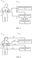
- FIG. 1 is a schematic block diagram illustrating a system 10 suitable for monitoring hemodynamics of a subject 12, according to some embodiments of the present invention.
- System 10 comprises a signal generating system 14 which provides one or more output electric signals 16 and transmits signal 16 to an organ 18 of subject 12.
- Signal(s) 16 can be transmitted via a medical lead as known in the art.
- Organ 18 can be any part of a body of human or animal.
- organ 18 is external organ so that the transmission of signals can be done non-invasively.
- Representative example of organ 18 include, without limitation, a chest, a hip, a thigh, a neck, a head, an arm, a forearm, an abdomen, a back, a gluteus, a leg and a foot.
- organ 18 is a chest.
- system 10 comprises a demodulation system 20 configured for receiving an input electrical signal 22 sensed from organ 18 responsively to output signal 16, and for modulating input signal 22 using output signal 16 to provide an in-phase component 24 and a quadrature component 26 of input signal 22.
- System 10 further comprises a processing system 28 which is configured for monitoring the hemodynamics based on in-phase component 24 and quadrature component 26.
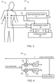
- FIG. 2 is a schematic block diagram of system 10.
- signal generating system 14 provides two signals, referred to herein as first output electric signal 32 and a second output electric signal 34, and transmits them to separate parts of organ of 18.
- signal 32 can be transmitted to the left side of organ 18 and signal 34 can be transmitted to the right side of organ 18.
- signals 32 and 34 are dependent signals.
- signals 32 and 34 can be independent signals.
- dependent signals means signals which are synchronized in at least one, more preferably at least two, more preferably any of: their frequency, phase and amplitude.
- independent signals means signals which are not synchronized in at least one, more preferably at least two, more preferably any of: their frequency, phase and amplitude.
- signal generating system 14 provides more than two (depended or independent) signals.
- processing system 28 receives first input electrical signal 36 sensed from the first part of organ 18 (the right side in the above example) responsively to first output signal 32, and a second input electrical signal 38 sensed from the second first part of organ 18 (the left side, in the above example) responsively to second output signal 34.
- Processing system 28 monitors the hemodynamics based on input signals 36 and 38.
- FIG. 1 the embodiment illustrated in FIG. 1 are combined with the embodiments illustrated in FIG. 2 .
- FIG. 3 A representative example of such combination is illustrated in FIG. 3 .
- generating system 14 provides two or more output signals, preferably, but not necessarily independent signals and transmits them to separate parts of organ of 18.
- generating system 14 provides two signals 32 and 34, and transmits them to the right and left sides of organ 18, respectively.
- demodulation system 20 receives an input electrical signal sensed from each part of organ 18 responsively to the respective output signal.
- demodulation system 20 can receive first input signal 36 sensed from the first part of organ 18 responsively to first output signal 32, and second input signal 38 sensed from the second first part of organ 18 responsively to second output signal 34.
- Demodulation system 20 modulates all input signals using the input signals to provide, for each input signal, an in-phase component and a quadrature component.
- demodulation system 20 preferably provides 2N signals, where N is the number of the received input signals.
- the output of system 20 is a first in-phase component 40 and a first quadrature component 42 both being demodulations of first input signal 36, and a second in-phase component 44 and a second quadrature component 46 both being demodulations of second input signal 38.
- the signals provided by generating system 14 are preferable alternate current (AC) signals which can be at any frequency. It was found by the present inventors that radiofrequency signals are useful, but it is not intended to limit the scope of the present invention to any particular frequency. Specifically, the frequency of the transmitted signals can be below the radiofrequency range, within the radiofrequency range or above the radiofrequency range.
- a representative frequency range suitable for the present embodiments include, without limitation, from 20 KHz to 800 KHz, e.g ., about 75 KHz.
- Current, generated by the signal generating system of the present embodiments flows across the organ and causes a voltage drop due to the impedance of the body.
- the input radiofrequency signals are typically, but not obligatorily, relate to the impedance of an organ of the subject.
- the parameters (e.g ., frequency, amplitude, phase) of the output signal(s) is selected such that the input signal is indicative of the impedance of organ 18.
- a typical pick to pick amplitude of the signal is, without limitation, below 600 mv.
- impedance the input signals are referred to below as “impedance”, but it should be understood that a more detailed reference to impedance is not to be interpreted as limiting the scope of the invention in any way, and that the signal be expressed as other measurable electrical quantities, including, without limitation, voltage, current, resistance, reactance, and any combination thereof.
- Z P denotes a Polar representation and Z C denotes a Cartesian representation
- is the absolute amplitude of the impedance
- • z is the phase of impedance
- Z r is the real component of the impedance
- Z i is the imaginary component of the impedance
- and • z can be detected using a Amplitude Modulation (AM) envelope detector, and a Phase Modulation (PM) detector, respectively, as disclosed for example, in WO2010032252 supra.
- AM Amplitude Modulation
- PM Phase Modulation
- demodulation system 20 it was found by the present inventors that it is advantage to directly extract from the signal the Cartesian components using quadrature demodulation, which preferably performed by demodulation system 20 for any input signal S received thereby.
- a preferred operational principle of demodulation system 20 is schematically illustrated in FIG. 4 .
- the signal and its components are to be understood as varying as function of the time.
- Received input signal R is multiplied, in parallel, by (i) a signal A which is in-phase with the transmitted output signal, and (ii) a signal B which is phase-shifted, typically using a phase-shifter 404, relative to the corresponding transmitted output signal T.
- This procedure provides two multiplication signals, R ⁇ A and R ⁇ B, respectively.
- the multiplication signals can be obtained using signal multipliers M A and M B .
- the multiplication signals R ⁇ A and R ⁇ B are then filtered using low pass filters 402.
- multiplication signals R ⁇ A and R ⁇ B are also using a high pass filter. This can be achieved, for example, by adding a high pass filter immediately before or immediately after filters 402, or by making filters 402 band pass filters.
- a typical cutoff frequency for the low pass filters is, without limitation from about 5 Hz to about 20 Hz or from about 5 Hz to about 15 Hz or from about 8 Hz to about 12 Hz, e.g., a cutoff frequency of about 9 Hz or less.
- a typical cutoff frequency for the high pass filters LPF is, without limitation from about 0.5 Hz to about 1.5 Hz, or from about 0.6 Hz to about 1.4 Hz or from about 0.7 Hz to about 1.3 Hz, e.g., a cutoff frequency of 0.8 Hz.
- the multiplication signals R ⁇ A and R ⁇ B are filtered by a dynamically adaptive filter, as further detailed hereinbelow.
- the dynamically adaptive filter can be in addition to one or both of filters 402. Alternatively, one or both of filters 402, can be replaced by the dynamically adaptive filter.
- the filtered signal obtained from R ⁇ A is referred to as the in-phase component I of the input signal R and the filtered signal obtained from R ⁇ B is referred to as the quadrature component Q of the input signal R.
- phase shifter generates a phase shift of ⁇ /2, so that B is ⁇ /2 shifted relative to T.
- phase shifter generates a phase shift which is other than ⁇ /2.
- quadrature component refers to any signal which is a result of the low-pass filtered multiplication between a received input signal R and a signal B which is phase-shifted with respect to the corresponding output signal T, wherein the phase-shift ⁇ of B relative to T is other zero.
- ⁇ is about ⁇ /2.
- the demodulation performed by system 20 can be using any known circuitry capable of performing quadrature demodulation.
- the circuitry can be digital or analog, as desired. In some embodiments of the present invention the circuitry is analog. Suitable analog circuitry is marked under catalog No. AD8333 of Analog Devices Analog Devices, Inc., Norwood, MA.
- demodulation system 20 performs the processing in a digital manner.
- demodulation system 20 comprises an analog to digital converter and a digital data processor or/and a digital signal processor or/and a field-programmable gate array.
- ADC analog to digital converter
- DSP digital signal processor
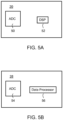
- FIG. 5A A representative example of a system 20 having an analog to digital converter (ADC) 50 and a digital signal processor (DSP) 52 is illustrated in FIG. 5A .
- Analog signals are received by ADC 50 are digitized according to a predetermined sampling rate and transmitted as vectors of discrete data to data DSP 52.
- a typical sample rate is, without limitation, from about 200 KHz to about 1.5 MHz.
- DSP 52 receives the input signal R and the transmitted signal T , and calculate the I and Q signals as further detailed hereinabove except that it is performed digitally.
- phase shifter 404, signal multipliers M A and M B , and filters 402 can each independently be digital elements.
- Processing system 28 serves for providing the monitoring information carried by the input signals.
- System 28 receives the signals from system 20 ( FIGs. 1 and 3 ) or directly from the organ ( FIG. 2 ), processes the signals and generates an output pertaining to the processed signals.
- the output is a graphical output, which is transmitted to a computer readable medium, such as a display card, a network card or memory medium of a computer. From the computer readable medium the output can be read by a local or remote computer and displayed, e.g ., on a display device.
- Processing system 28 performs the processing in a digital manner.
- processing system 28 can comprise an analog to digital converter and a digital data processor or a digital signal processor.
- demodulation system 20 is digital, it is not required for processing system 28 to include an analog to digital converter since in these embodiments processing system 28 receives digital signals from demodulation system 20.
- FIG. 5B A representative example of a system 28 having an analog to digital converter (ADC) 54 and a data processor 56 is illustrated in FIG. 5B .
- ADC analog to digital converter
- the analog signals are received by ADC 54, digitized according to a predetermined sampling rate and transmitted as vectors of discrete data to data processor 56.
- a typical sample rate is, without limitation, from about 200 Hz to about 800 Hz.
- Data processor 56 can be a general purpose computer or dedicated circuitry.
- Computer programs implementing the processing technique of the present embodiments can commonly be distributed to users on a distribution medium such as, but not limited to, a floppy disk, CD-ROM or flash memory. From the distribution medium, the computer programs can be copied to a hard disk or a similar intermediate storage medium. Alternatively, the computer program can be distributed as a data stream downloadable, e.g ., from an http or ftp internet site, in which case the computer program is copied to the computer directly from the internet site.
- the computer programs can be run by loading the computer instructions either from their distribution medium or their intermediate storage medium into the execution memory of the computer, configuring the computer to act in accordance with the method of this invention. All these operations are well-known to those skilled in the art of computer systems.
- Processing system 28 can provide hemodynamic monitoring in more than one way.
- system 28 generates a separate output based on each of the signals as received by system 20.
- the output can include a graphical representation (e.g., as a function of the time) of the signals themselves, or their time-derivative (e.g., first time-derivative) or the area under the curves of the signals.
- System 28 performs a normalization procedure before generating the output, for example, to obtain similar scales for different output types.
- system 28 generates an output based on a combination of signals as received by system 20. Representative examples of such combinations are provided hereinbelow. When more than one combination is calculated by system 28 a separate output can be provided for each signal combination.
- system 28 applies a dynamically adaptive filter to the signal before displaying it.
- the filtration is preferably performed responsively to the physiological condition of the subject.
- the filtration can be done, for example, by employing the filtering techniques described in International Patent Publication No. 2009/022330 , separately to the phase and to the absolute components.
- the dynamically variable filter filters the data according to a frequency band which is dynamically adapted in response to a change in the physiological condition of the subject. It was found by the Inventors of the present invention that the dynamical adaptation of the frequency band to the physiological condition of the subject can significantly reduce the influence of unrelated signals on the measured property.
- system 28 employs a process in which first the physiological condition of the subject is determined, then a frequency band is selected based on the physiological condition of the subject, and thereafter the received signals are filtered according to frequency band.
- the frequency band is dynamically adapted in response to a change in the physiological condition.
- the physiological condition is preferably, but not obligatorily, the heart rate of the subject.
- the data pertaining to the physiological condition can be collected via a suitable data collection unit either in analog or digital form, as desired.
- the physiological condition can be a heart rate which can be determined, e.g ., by analysis of ECG signals or the like.
- physiological condition which is a heart rate
- the physiological condition is a ventilation rate of the subject, a repetition rate of a particular muscle unit and/or one or more characteristics of an action potential sensed electromyography.
- the adaptation of the frequency band to the physiological condition can be according to any adaptation scheme known in the art.
- one or more parameters of the frequency band e.g ., lower bound, upper bound, bandwidth, central frequency
- a parameter characterizing the physiological condition e.g ., the number of heart beats per minute.
- FIGs. 6A and 6B show representative examples of a dynamically varying frequency bounds, which can be employed according to some embodiments of the present invention separately to each signal received by system 28 and/or collectively to any combination of signals as further detailed hereinbelow.
- FIGs. 6A and 6B Shown in FIGs. 6A and 6B is the functional dependence of the frequency bounds (upper bound in FIG. 6A and lower bound in FIG. 6B ) on the heart rate of the subject.
- the upper bound of the frequency band varies linearly such that at a heart rate of about 60 beats per minute (bpm) the upper bound is about 6 Hz, and at a heart rate of about 180 bpm the upper bound is about 9 Hz.
- the lower bound of the frequency band varies linearly such that at a heart rate of about 60 the lower bound is about 0.9 Hz bpm and at a heart rate of about 180 bpm the lower bound is about 2.7 Hz.
- the upper bound equals Fu(HR) at all times, while in other embodiments, the upper bound is set using an iterative process.
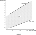
- FIG. 6C A dynamically varying band pass filter (BPF) characterized by a dynamically varying upper frequency bound and a dynamically varying lower frequency bound, according to some embodiments of the present invention is illustrated in FIG. 6C .
- each heart rate is associated with a frequency band defined by a lower bound and an upper bound.
- FIG. 6C depicts a BPF in which the lower bound is about 0.9 Hz and the upper bound is about 6 Hz.
- the values presented above and the functional relations illustrated in FIGs. 6A-C are exemplary embodiments and should not be considered as limiting the scope of the present invention in any way.
- the functional relations between the frequency band and the physiological condition can have different slopes and/or offsets, or they can be non-linear.
- the iterative process can, in some embodiments, be based a comparison between a value of a physiological parameter as extracted or calculated from the respective filtered component and a value of the same physiological parameter as extracted or calculated from a reference signal, for example, an ECG signal.
- physiological parameter refers to any variable parameter which is measurable or calculable and is representative of a physiological activity, particularly, but not necessarily, activity of the heart.
- the physiological parameter is other than the heart rate per se.
- the physiological parameter can be a time-related parameter, amplitude-related parameters or combination thereof.
- the filter signal and the reference signal are expressed in terms of amplitude as a function of the time.
- time-related parameters are typically calculated using abscissa values of the signals and amplitude-related parameters are is typically calculated using ordinate values of the signals.
- time-related physiological parameters suitable for the present embodiments include, without limitation, systolic time, diastolic time, pre-ejection period and ejection time.
- a representative example of amplitude-related physiological parameter suitable for the present embodiments includes, without limitation, maximal amplitude above zero during a single beat, maximal peak-to-peak amplitude during a single beat, and RMS level during a single beat.
- various slopes parameters such as, but not limited to, the average slope between two points over the signal.
- the physiological parameter is a ventricular ejection time (VET).
- VET ventricular ejection time
- the present inventors discovered that a significant amount of the biological information for a particular subject can be obtained from a frequency range between F L (HR) and 5.5 Hz, where HR is the heart rate of the subject. It was further discovered by the present inventors that for some medical conditions some of the information can reside between 5.5 Hz and F u (HR).
- the advantage of the comparison between two different techniques for extracting or calculating the same physiological parameter is that it allows to substantially optimize the upper frequency bound of the band pass filter.
- the comparison in each iteration of the iterative process, the comparison is repeated. If the comparison meets a predetermined criterion, the upper frequency bound is updated by calculating an average between a low threshold for the upper bound and a high threshold for the upper bound.
- the lower frequency bound can be a constant bound, e.g., a constant frequency which is from about 0.9 Hz to about 2.7 Hz), or it can be dynamic, e.g., F L (HR), HR being the heart rate of the subject before or during the respective iteration.
- the low and high thresholds for the upper bound can be set in more than one way.
- the low and high thresholds are predetermined (namely they determined a priori before the iterative process), in some embodiments, the thresholds are set in a previous iteration of iterative process, in some embodiments one of the thresholds is predetermined and the other threshold is set in a previous iteration of iterative process.
- the first iteration is based on two thresholds which are determined a priori before the iterative process. It was found by the inventors of the present invention that, at least initially (i.e.
- the first threshold can be about Fu(40), which in various exemplary embodiments of the invention is about 5.5 Hz, and the second threshold can be the calculated value of Fu(HR), HR being the heart rate of the subject before or during the respective iteration.
- the predetermined criterion used during the iterations can be, for example, that the results of the two calculations are similar ( e.g ., within about 40 % or 30 % or 25 % of each other).
- the predetermined criterion can also relate to the direction of difference between the two calculations.
- the upper bound is updated if the value of the parameter as calculated based on the reference signal is higher than value of the parameter as calculated based on the filtered signal
- the upper bound is updated if the value of parameter as calculated based on the reference signal is lower than the value of the parameter as calculated based on the filtered signal.
- the upper bound is typically updated if the value of the parameter as calculated based on the reference signal is higher than the value of the parameter as calculated based on the filtered signal.
- a Boolean combination between the above criteria can also be used as a criterion.
- an AND Boolean combination can be employed in which case the upper frequency bound can be updated if the results of the two calculations are similar and the calculation according to the filtered signal indicates an abnormal physiological condition while the calculation according to the reference signal indicates a normal physiological condition.
- processing system 28 combines input signals as obtained from each part of organ 18 ( e.g ., 36 and 38 ).
- the combination can be linear or non-linear combination.
- processing system 28 combines the in-phase component with the quadrature component (e.g. , components 24 and 26 ).
- processing system 28 combines, for each input signal, a respective in-phase component with a respective quadrature component. For example, for first input signal 36, system 28 can combine first in-phase component 40 with first quadrature component 42, and for second input signal 38, system 28 can combine second in-phase component 44 with second quadrature component 46.
- processing system 28 is configured to combine two or more hybrid signals.
- processing system 28 combines phase-amplitude hybrid signals corresponding to two or more input signals.
- any of the weight parameters w L , w R , w I , w Q , w iR , w rR , w iL , w rL , w CR , w CL , w iR , w iL , w rR , w rL , w AML , , w PML, w AMR , w PMR , w PR and w PL ; and any of the power parameters ⁇ L , ⁇ R , ⁇ I , ⁇ Q , ⁇ R , ⁇ L , ⁇ R , ⁇ L , ⁇ L , ⁇ L , ⁇ R , ⁇ R and ⁇ L can be found prior to the monitoring for example, using a calibration curve.
- Typical values for the weight parameters include, without limitation, any value from 0 to about 10, and typical values for the power parameters, include, without limitation any value from
- a normalization factor is employed.
- the normalization factor can be included in any of the signals of the present embodiments, including the signals listed in EQs. 5-15 or derivatives thereof or the area under their curves.
- the parameters W NF and a can be found, for example, using a calibration curve.
- Typical values for W NF parameter include, without limitation, any positive number up to about 5, and typical values for the power parameter a include, without limitation, any number from about -10 to 0.
- the parameters c, d, m and n can be found, for example, using a calibration curve. Typical values for the parameters c and d include, without limitation, any number from 0 to about 0.6 radians, and typical values for the parameters m and n include, without limitation, any number from -5 to about 5 radians.
- a time-derivative e.g ., a first time derivative
- the time derivative can be calculated numerically.
- any of the signals of the present embodiments can be used for assessing one or more properties pertaining to the hemodynamics of the organ.
- the property is calculated based on at least one signal selected from the group consisting of the combined signal S LR (see, e.g., EQ. 5), the combined hybrid signal S CT (see, e.g., EQ. 9), and the combined phase-amplitude hybrid signal S PT ( see , e.g., EQ. 15).
- system 28 can generate an output based on the calculated properties or their time-derivative.
- the output can include a graphical representation, e.g., the calculated property as a function of the time.
- properties pertaining to the hemodynamics of the organ can be calculated using any technique known in the art, such as, but not limited to, the technique disclosed in International Publication Nos. WO2004/098376 , WO2006/087696 , WO2008/129535 , WO2009/022330 and WO2010/032252 .
- Representative examples of properties that can be calculated according to some embodiments of the present invention include, stroke volume (SV), cardiac output (CO), ventricular ejection time (VET), cardiac index (CI), thoracic fluid content (TFC), total peripheral resistance index (TPRI), blood vessel compliance and any combination thereof.
- SV stroke volume
- CO cardiac output
- VET ventricular ejection time
- CI cardiac index
- TFC thoracic fluid content
- TPRI total peripheral resistance index
- blood vessel compliance and any combination thereof.
- the VET can be extracted from the morphology of the pulses of the signal being used for the calculation.
- points of transitions are identified on the pulse and the time interval between two such points is defined as the VET.
- FIG. 7 An exemplified procedure is illustrated in FIG. 7 , which illustrates a typical morphology of a single beat of a signal S and its first derivative dS / dt, as a function of the time.
- Signal S can be any of the signals of the present embodiments, e.g ., S LR or S CT or S PT , following the application of a dynamically varying filter as further detailed hereinabove.
- the derivative d S / d t has two zeroes O 1 and O 2 over the beat, with a point of local maximum M 1 between the zeroes and a point of local minimum M 2 after the second zero.
- the VET is defined as the time period (difference between the abscissa values) between the first zero O 1 and the first minimum M 2 after the second zero Oz.
- the stroke volume SV and the cardiac output CO can be calculated based on dS/dt, a characteristic time-interval T and one or more global characteristics of the subject such as, but not limited to, the weight, height, age, BMI and gender of the subject.
- the time-interval is VET.
- the function f can be universal to all subjects, in which f does not vary with c subject .
- the parameters w 1 , w 2 , ..., w 6 are weight parameters and the parameters p 1 , p 2 , ..., p 5 are power parameters.
- weight parameters w 1 , w 2 , ..., w 6 and power parameters p 1 , p 2 , ..., p 5 can be found, for example, using a calibration curve.
- Typical values for the weight parameters w 1 , w 2 , ..., w 6 include, without limitation, any number from about 10 -10 to about 10 2
- typical values for the power parameters p 1 , p 2 , ..., p 5 include, without limitation, any number from -2 to about 2.
- the calculated cardiac output can be used for estimating the exercise capacity of the subject.
- the exercise capacity correlates with the cardiac output. For example, when the cardiac output is below a predetermined threshold, processing system 28 can estimate that the subject's exercise capacity is low, and when the cardiac output is above a predetermined threshold, the method can estimate that the subject's exercise capacity is high. It was demonstrated by the present inventors that during exercise the cardiac output among normal subjects is about 34 % higher than that of Congestive Heart Failure (CHF) patients.
- CHF Congestive Heart Failure
- the system of the present embodiments can therefore be used to assess or determine worsening of the condition of the subject, particularly subjects with congestive heart failure.
- a cardiopulmonary exercise testing is performed to provide one or more cardiopulmonary exercise (CPX) measures.
- the cardiac output can be combined with the CPX measure(s) and the combination can be used to estimate the exercise capacity, and/or to assess the quality of the estimation.
- the maximal cardiac output is inversely correlated to the VE/VCO 2 slope, where VE is the ventilation efficiency and VCOz is the carbon dioxide production rate.
- the correlation coefficient between the maximal cardiac output during exercise and the VE/VCO 2 slope can be calculated and the quality of the exercise capacity estimation can be assessed based on this correlation coefficient, where negative and large in absolute value correlation coefficient corresponds to high quality of exercise capacity estimation and vice versa.
- the maximal cardiac output is directly correlated to the oxygen uptake efficiency slope OUES.
- the correlation coefficient between the maximal cardiac output during exercise and the OUES can be calculated and the quality of the exercise capacity estimation can be assessed based on this correlation coefficient, where high positive correlation coefficient corresponds to high quality of exercise capacity estimation and vice versa.
- the calculated cardiac output can be used for identifying sleep apnea events.
- the present inventors conducted experiments in which cardiac output response to positive end expiratory pressure was evaluated. Without being bound to any theory, it is postulated that positive end expiratory pressure can be surrogate for sleep apnea because it creates positive thoracic pressure induced by mechanical ventilation in anesthetized subjects in intensive care units. The pressure dynamics in positive end expiratory pressure are similar to those observed during an apnea episode.
- an apnea event is identified when the cardiac output is reduced by at least 30 %, more preferably at least 40 %, more preferably at least 50 % over a time period of less than two minutes.
- arterial oxygen saturation (SPOz) is monitored, for example, conventional non-invasive pulse oximeter.
- a lower threshold of comprises reduction can be employed.
- an apnea event can be identified when the calculated cardiac output is reduced by at least 25 % and the value of SPOz is significantly decreased (say, by more than 40 %).
- the hemoglobin concentration of the subject is estimated or received as input, and used for estimating blood oxygen content.
- the blood oxygen content can be supplemented to the calculated cardiac output for the purpose of improving sensitivity and/or specificity.
- the total oxygen delivery is estimated.
- the total oxygen delivery can be estimated by combining the cardiac output, oxyhemoglobin saturation and hemoglobin concentration. For example, total oxygen delivery rate (typically expressed in units of mL of oxygen per minute) can be estimated by multiplying the cardiac output by the oxygen content.
- system 10 can generate a wakening alarm sensible by the sleeping subject.
- the present embodiments can also be employed for subjects who already been diagnosed with sleep apnea and for whom a CPAP device has been prescribed. Specifically, the present embodiments can be used as a supplement to a conventional treatment (e.g ., a CPAP device) so as to assess the efficacy of treatment. For example, the present embodiments can be used for determining whether or not a sufficient amount of oxygen is delivered to vital organs such as the brain, heart and kidneys. It is recognized that even when a CPAP device pushes air to the lungs, oxygen delivery from the cardio-pulmonary system to vital tissues is not guaranteed. For example, a significant drop in cardiac output may result in insufficient oxygen delivery even when the CPAP device increases the oxygen content in the blood.
- a system can signal the CPAP device to increase the positive airway pressure and/or generate a wakening signal sensible by the sleeping subject.
- a CPAP device when the total oxygen delivery falls below the predetermined threshold system 10 can control a CPAP device to increase pressure.
- the calculated property can also be used for predicting onset of electromechanical dissociation. It was found by the present inventors that the onset of electromechanical dissociation can be predicted ahead of time, unlike traditional techniques which only provide post occurrence identification of electromechanical dissociation.
- the present embodiments predict electromechanical dissociation onset by providing a quantitative estimate of the mechanical activity of the heart while monitoring its electrical activity. Specifically, according to the present embodiments onset of electromechanical dissociation is likely to occur, if the flow rate characterizing the mechanical activity of the heart is lower then one predetermined threshold while the rhythm characterizing the electrical activity of the heart remains above another predetermined threshold.
- an electrocardiac signal e.g., electrocardiogram (ECG) signal or a signal which correlates with an ECG signal
- ECG electrocardiogram
- the electrocardiac signal can be obtained from an external source, or be extracted from the signal of the present embodiments.
- the electrocardiac signal comprises a DC signal or a signal characterized by very low frequency (less than 150 Hz).
- ECG signals for example, are typically characterized by amplitudes of 0.1-5 mV and frequencies of 0.05-130 Hz.
- the extraction of DC signal or a very low frequency signal can be done using a suitable electronic circuitry or device which receives the signal of the present embodiments and filter out high frequency (typically radiofrequency) components.
- a suitable electronic circuitry or device which receives the signal of the present embodiments and filter out high frequency (typically radiofrequency) components.
- Such electronic circuitries are known in the art.
- a feedback capacitor or an integrator type electronic circuitry can be constituted to extract the electrocardiac signal.
- the electronic circuitry can amplify the electrocardiac signal as known in the art.
- the electrical activity of the heart can be assessed based on the electrocardiac signal.
- one or more repetitive patterns are identified in the electrocardiac signal, and the repetition rate of the identified patterns is measured.
- the electrocardiac signal is an ECG signal
- the QRS complex can be identified, and the QRS rate can be measured, for example, by measuring the RR interval and defining the rate as the inverse of the RR interval.
- the mechanical activity of the heart can be assessed based on the calculated property, preferably, but not necessarily the cardiac output or cardiac index or stroke volume.
- processing system 28 predicts the onset of electromechanical dissociation (EMD) or Pulseless Electrical Activity (PEA) according to predetermined criteria. Generally, when the electrical activity is above a predetermined threshold and the mechanical activity is below a predetermined threshold, processing system 28 predicts onset of EMD or PEA.
- EMD electromechanical dissociation
- PEA Pulseless Electrical Activity
- the predetermined threshold for the mechanical activity can be about X liters per minute, where X is a number ranging from about 1 to about 1.5.
- a baseline cardiac output for the subject can be defined and compared to the instantaneous cardiac output.
- the predetermined threshold for the mechanical activity can be defined as 70 % or 60 % or 50 % of the baseline.
- the predetermined threshold for the mechanical activity can be about Y liters per minute per square meter, where Y is a number ranging from about 0.75 to about 1.
- a baseline cardiac index for the subject can be defined and compared to the instantaneous cardiac index, wherein the predetermined threshold for the mechanical activity can be defined as 70 % or 60 % or 50 % of the baseline.
- the onset of EMD can be predicted if the cardiac output is reduced by at least 50% and the electrical activity is characterized by pulse rate of at least 60 pulses per minute.
- the onset of EMD can also be predicted if, over a period of about five minutes, the cardiac output is less than 1 liter per minute and the electrical activity is characterized by a rhythm of at least 40 cycles per minute.
- the onset of EMD can also be predicted if, over a period of about five minutes, the cardiac index is less than 1 liter per minute per square meter and the electrical activity is characterized by a rhythm of at least 40 cycles per minute.
- the onset of EMD can be predicted if, over a period of about five minutes, the cardiac index is less than 0.75 liter per minute per square meter and the electrical activity is characterized by a rhythm of at least 40 cycles per minute.
- the morphology of the signal of the present embodiments can be used according to some embodiments of the present invention to calculate the likelihood that the subject develops sepsis.
- a sepsis indicator is extracted from the pulse morphology, and the likelihood is assessed based on the sepsis indicator.
- the assessment can be done, for example, by thresholding, wherein the sepsis indicator as obtained from the pulse morphology is compared to a predetermined threshold which can be used as a criterion to assess whether or not the subject is likely to develop sepsis.
- the sepsis indicator is a ratio between the time-derivative of the obtained signal (e.g ., S LR or S CT or S PT ) and the ventricular ejection time.
- this ratio reflects the relative behavior of contractility per time to eject.
- this ratio also reflects the cardiac work against the after load pressures.
- the heart contracts in relatively enhanced contractile force against a low after load. This results in a higher value of the ratio.
- a ratio can be used according to some embodiments of the present invention for assessing the likelihood for the subject to develop sepsis.
- the present inventors conducted experiments and uncovered that this ratio can be used as a discriminator for screening septic and non-septic subjects. It was found that for septic subjects, this ratio is generally high, wherein for non-septic subjects this ratio is generally low.
- the ratio is compared to a predetermined threshold, wherein a ratio above the predetermined threshold indicates that the subject is likely to develop sepsis, and a ratio above the predetermined threshold indicates that the subject is not likely to develop sepsis.
- Typical values for the predetermined threshold are from about 0.5 to about 0.8, or from about 0.6 to about 0.8, e.g., about 0.7. It was found by the present inventors that using such threshold, the likelihood is characterized by a p-value less than 0.1, e.g., 0.05.
- a report is issued.
- the report can include the assessed likelihood and other parameters, particularly statistical parameters (e.g ., characteristic p-value and the like).
- the signals of the present embodiments can also be used for other applications including, without limitation, predicting body cell mass, fat free mass and/or total body water of a subject, for example, as disclosed in U.S. Patent No. 5,615,689 ; determining hematocrit of blood in a body part of a subject, for example, as disclosed in U.S. Patent No. 5,642,734 ; monitoring hydration status of a subject, for example, as disclosed in U.S. Published Application No. 20030120170 ; discriminating tissue, for example, as disclosed in U.S. Published Application No. 20060085048 ; and calculating the circumference of a body segment for example, as disclosed in U.S. Published Application No. 20060122540 .
- compositions, method or structure may include additional ingredients, steps and/or parts, but only if the additional ingredients, steps and/or parts do not materially alter the basic and novel characteristics of the claimed composition, method or structure.
- a compound or “at least one compound” may include a plurality of compounds, including mixtures thereof.
- range format is merely for convenience and brevity and should not be construed as an inflexible limitation on the scope of the invention. Accordingly, the description of a range should be considered to have specifically disclosed all the possible subranges as well as individual numerical values within that range. For example, description of a range such as from 1 to 6 should be considered to have specifically disclosed subranges such as from 1 to 3, from 1 to 4, from 1 to 5, from 2 to 4, from 2 to 6, from 3 to 6 etc., as well as individual numbers within that range, for example, 1, 2, 3, 4, 5, and 6. This applies regardless of the breadth of the range.
- a prototype system was built according to some embodiments of the present invention.
- the system included circuitry for generating and transmitting the output signals are receiving and demodulating the input signals.
- the circuitry is illustrated in FIG. 8 .
- the prototype system included left and right lead transmitters and two I/Q detectors for the detection of the thoracic impedance. Transmitted low current sinusoidal signals from a current source were transmitted, via balun circuits, separately to a left lead and a right lead (T xL and T xR ). The signals were transmitted to the thorax via dedicated transmitting electrodes that were attached to the skin.
- the received modulated signals from each lead (R xL and R xR ) were filtered using a high pass filter having a cutoff frequency of about 50 Hz, and thereafter multiplied, in parallel, by (i) T xL and T xR , respectively, and (ii) T xL and T xR after they were shifted by ⁇ /2.
- the two resulting multiplication signals from each lead underwent a band pass filter with upper cutoff selected to obtained the in-phase and quadrature signals and low cutoff for eliminating respiratory, resulting in a left and right in-phase components (I_L, I_R, respectively) and a left and right quadrature components (Q_L, Q_R, respectively).
- the lower and upper cutoff frequencies of the band pass filter were 0.8 Hz and 9 Hz, respectively.
- an ultrasonic flow probe was adjusted to the ascending Aorta and for the dogs a Electromagnetic flow probe was adjusted to the ascending Aorta both devices are considered Gold Standard in measuring the flow from the Left Ventricle to the aorta.
- a Fr. micromanometer was inserted into the left ventricle via a stab in the apex and secured with a purse string suture for the measurement of pressure and volume within the left ventricle.
- FIG. 9A shows the left ventricle volume signal in ml as derived by the Micromanometer (blue) synchronized with the ECG signal (black), as a function of time in seconds.
- the ECG is scaled for display purposes.
- FIG. 9B shows the signal S CT (t) in ml (red) synchronized with the ECG signal in black. Both the S CT signal and the ECG signal are scaled for display purposes.
- FIGs. 9A-B demonstrate that the signal S CT (t) of the present embodiments correlates well with the volume of blood in the ventricles of the heart.
- FIG. 10 shows the left ventricle flow signal as derived by the ultrasonic flow probe (blue), synchronized with the ECG signal (red), as a function of time in seconds.
- FIG. 10 also shows the dS CT (t) signal of the present embodiments (black). Both the dS CT signal and the ECG signal are scaled for display purposes.
- FIG. 10 demonstrates that the area under the positive curve of the signal dS CT (t) correlates well with the flow of blood from the left ventricle to the aorta.
- FIG. 11 shows the mean cardiac output in liters/minute as derived by the aortic ultrasonic flow probe (blue), and the mean cardiac output derived by the dS CT (t) signal of the present embodiments (red), during infusion of Dobutamine, as a function of the time in seconds.
- FIG. 11 demonstrates that the signal dS CT (t) of the present embodiments correlates with high precision the heamodynamic behavior.
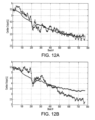
- FIG. 12A shows, as a function of the number of heart beat, the mean cardiac output in liters/minute as derived by the aortic ultrasonic flow probe (blue), and the mean cardiac output in liters/minute derived by the signal dS CL (t) of the present embodiments (black), after the infusion of Dobutamine was ended.
- the signal dS CL (t) is scaled.
- FIG. 12B shows, as a function of the number of heart beat, the mean cardiac output in liters/minute (blue) as derived by the aortic ultrasonic flow probe, and the mean cardiac output in liters/minute as derived by the signal dS CR (t) of the present embodiments (black).
- the signal dS CR (t) is scaled and is presented at the same time frame as in FIG. 12A .
- the left lead showed more correlation with the reference compared to the right lead.
- FIG. 13A shows, as a function of the number of heart beat, the mean cardiac output in liters/minute derived by an aortic ultrasonic flow probe (blue), and the mean cardiac output in liters/minute as derived by the signal dS CR (t) of the present embodiments (black), during progression of Severe Edema.
- the signal dS CR (t) is scaled.
- FIG. 13B shows, as a function of the number of heart beat, the mean cardiac output in liters/minute as derived by an aortic ultrasonic flow probe (blue), and the mean cardiac output in liters/minute as derived by the signal dS CL (t) of the present embodiments (black).
- the signal dS CL (t) is scaled and is presented at the same time frame as in FIG. 13A .
- the right lead showed more correlation with the reference compared to the left lead.
- the present example demonstrates that the hemodynamic trends invoked by drug titration and captured with the experimental system of the present embodiments correlated well with the Gold Standard in S CL (t) (see FIGs. 12A-B ) and hemodynamic trends invoked by fluid challenge or respiratory challenged were described in high correlation in S CR (t) (see FIGs. 13A-B ).
- FIG. 14 shows, as a function of the number of heart beat, the mean cardiac output in liters/minute as derived by an aortic ultrasonic flow probe (blue), and mean cardiac output in liters/minute derived by the signal dS PT (t) of the present embodiments (black), during infusion of 500cc fluid bolus.
- the signal dS PT (t) is scaled.
- FIG. 14 demonstrates that the signal S PT (t) correlates with the cardiac output of the reference.
Landscapes
- Health & Medical Sciences (AREA)
- Life Sciences & Earth Sciences (AREA)
- Engineering & Computer Science (AREA)
- Physics & Mathematics (AREA)
- Medical Informatics (AREA)
- Pathology (AREA)
- Biomedical Technology (AREA)
- Heart & Thoracic Surgery (AREA)
- Biophysics (AREA)
- Molecular Biology (AREA)
- Surgery (AREA)
- Animal Behavior & Ethology (AREA)
- General Health & Medical Sciences (AREA)
- Public Health (AREA)
- Veterinary Medicine (AREA)
- Cardiology (AREA)
- Physiology (AREA)
- Hematology (AREA)
- Nuclear Medicine, Radiotherapy & Molecular Imaging (AREA)
- Radiology & Medical Imaging (AREA)
- Computer Vision & Pattern Recognition (AREA)
- Psychiatry (AREA)
- Signal Processing (AREA)
- Artificial Intelligence (AREA)
- Vascular Medicine (AREA)
- Immunology (AREA)
- Pulmonology (AREA)
- Optics & Photonics (AREA)
- Measuring Pulse, Heart Rate, Blood Pressure Or Blood Flow (AREA)
- Measurement And Recording Of Electrical Phenomena And Electrical Characteristics Of The Living Body (AREA)
- Measurement Of The Respiration, Hearing Ability, Form, And Blood Characteristics Of Living Organisms (AREA)
- Measuring And Recording Apparatus For Diagnosis (AREA)
Description
- This application claims the benefit of priority of
U.S. Provisional Patent Application No. 61/511,163 filed on July 25, 2011 - The present invention, in some embodiments thereof, relates to the medical field and, more particularly, but not exclusively, to a method and system for monitoring hemodynamics.
- Heart diseases are major causes of morbidity and mortality in the modern world. Generally, heart diseases may be caused by (i) a failure in the autonomic nerve system where the impulses from the central nervous system control to the heart muscle fail to provide a regular heart rate and/or (ii) an insufficient strength of the heart muscle itself where even though the patient has a regular heart rate, its force of contraction is insufficient. Either way, the amount of blood or the rate at which the blood is supplied by a diseased heart is abnormal and it is appreciated that an assessment of the state of a patient's circulation is of utmost importance.
- The simplest measurements, such as heart rate and blood pressure, may be adequate for many patients, but if there is a cardiovascular abnormality then more detailed measurements are needed.
- Cardiac output (CO) is the volume of blood pumped by the heart during a time interval, which is typically taken to be a minute. Cardiac output is the product of heart rate (HR) and the amount of blood which is pumped with each heartbeat, also known as the stroke volume (SV). For example, the stroke volume at rest in the standing position averages between 60 and 80 ml of blood in most adults. Thus, at a resting heart rate of 80 beats per minute the resting cardiac output varies between 4.8 and 6.4 L per min.
- Several methods of measuring cardiac output are presently known.
- One such method employs transoesophageal echocardiography (TOE) which provides diagnosis and monitoring of a variety of structural and functional abnormalities of the heart. TOE is used to derive cardiac output from measurement of blood flow velocity by recording the Doppler shift of ultrasound reflected from the red blood cells. The time velocity integral, which is the integral of instantaneous blood flow velocities during one cardiac cycle, is obtained for the blood flow in a specific site (e.g., the left ventricular outflow tract). The time velocity integral is multiplied by the cross-sectional area and the heart rate to give cardiac output.
-
U.S. Patent No. 6,485,431 discloses a technique in which the arterial pressure, measured by a pressure cuff or a pressure tonometer, is used for calculating the mean arterial pressure and the time constant of the arterial system in diastole. The compliance of the arterial system is then determined from a table and used for calculating the cardiac output as the product of the mean arterial pressure and compliance divided by a time constant. - An additional method of measuring cardiac output is known as thermodilution. This method is based on a principle in which the cardiac output can be estimated from the dilution of a bolus of saline being at a different temperature from the blood. The thermodilution involves an insertion of a fine catheter into a vein, through the heart and into the pulmonary artery. A thermistor, mounted on the tip of the catheter senses the temperature in the pulmonary artery. A bolus of saline (about 5 ml. in volume) is injected rapidly through an opening in the catheter, located in or near to the right atrium of the heart. The saline mixes with the blood in the heart and temporarily depresses the temperature in the right atrium. Two temperatures are measured simultaneously: the blood temperature is measured by the thermistor sensor on the catheter and the temperature of the saline to be injected is typically measured by means of a platinum temperature sensor. The cardiac output is inversely related to the area under the curve of temperature depression.
- A non-invasive method, known as thoracic electrical bioimpedance, was first disclosed in
U.S. Patent No. 3,340,867 and has recently begun to attract medical and industrial attention (see, e.g.,U.S. Patent Nos. 3,340,867 ,4,450,527 ,4,852,580 ,4,870,578 ,4,953,556 ,5,178,154 ,5,309,917 ,5,316,004 ,5,505,209 ,5,529,072 ,5,503,157 ,5,469,859 ,5,423,326 ,5,685,316 ,6,485,431 ,6,496,732 and6,511,438 ;U.S. Patent Application No. 20020193689 ]. The thoracic electrical bioimpedance method has the advantages of providing continuous cardiac output measurement at no risk to the patient. - Various methods employing bioimpedance are found in: International Publication Nos.
WO2004098376 ,WO2006087696 ,WO2008129535 ,WO2009022330 andWO2010032252 all assigned to the common assignee of the present invention.U.S. Patent Application No. 5,642,734 A discusses a method and apparatus for noninvasively determining hematocrit utilizing the frequency-dependent electrical impedance characteristics of whole blood by electrically stimulating a patient body portion containing a vascular compartment with a current source over a range of frequencies. U.S. Patent Application No.US 2009/240133 A1 discusses a radio apparatus and method for non-invasive, thoracic radio interrogation of a subject for the collection of hemodynamic, respiratory and/or other cardiopulmonary related data from the subject. - According to an aspect of some embodiments of the present invention there is provided a system as set forth in the appended claims.
- According to an aspect of some embodiments of the present invention there is provided a method as set forth in the appended claims.
- Some embodiments of the invention are herein described, by way of example only, with reference to the accompanying drawings. With specific reference now to the drawings in detail, it is stressed that the particulars shown are by way of example and for purposes of illustrative discussion of embodiments of the invention. In this regard, the description taken with the drawings makes apparent to those skilled in the art how embodiments of the invention may be practiced.
- In the drawings:
-
FIG. 1 is a schematic block diagram illustrating a system suitable for monitoring hemodynamics of a subject, according to some embodiments of the present invention; -
FIG. 2 is a schematic block diagram illustrating the system, according to other embodiments of the present invention; -
FIG. 3 is a is a schematic block diagram illustrating a system which is a combination of the system illustrated inFIG. 1 and the system illustrated inFIG. 2 , according to some embodiments of the present invention; -
FIG. 4 is a schematic illustration of an operational principle of a demodulation system according to some embodiments of the present invention; -
FIGs. 5A and 5B are schematic block diagrams of a demodulation system (FIG. 5A ) and a processing system (FIG. 5B ) according to some embodiments of the present invention; -
FIGs. 6A and 6B show representative examples of a dynamically varying frequency bounds, according to some embodiments of the present invention; -
FIG. 6C shows a dynamically varying band pass filter (BPF), according to some embodiments of the present invention; -
FIG. 7 is a schematic illustration of a typical morphology of a single beat of a signal and its first derivative, as a function of the time, according to some embodiments of the present invention; -
FIG. 8 is a schematic illustration of a prototype system built according to some embodiments of the present invention; -
FIG. 9A shows the left ventricle volume signal in ml (blue) as derived by a 3-Fr Micromanometer secured with a purse string suture, as a function of time, synchronized with the ECG signal (black); -
FIG. 9B shows a signal SCT(t) obtained according to some embodiments of the present invention (red) synchronized with the ECG signal (black); -
FIG. 10 shows a left ventricle flow signal as derived by an ultrasonic flow probe around the ascending aorta (blue), and a dSCT(t) signal obtained according to some embodiments of the present invention (black); -
FIG. 11 shows mean cardiac output as derived by an aortic ultrasonic flow probe (blue), and mean cardiac output derived by a dSCT(t) signal obtained according to some embodiments not part of the present invention (red) during infusion of Dobutamine; -
FIG. 12A shows mean cardiac output as derived by an aortic ultrasonic flow probe (blue), and mean cardiac output derived by a dSCL(t) signal obtained according to some embodiments not part of the present invention (black), after infusion of Dobutamine; -
FIG. 12B shows mean cardiac output as derived by an aortic ultrasonic flow probe as a function of the number of heart beat (blue), and mean cardiac output derived by a dSCR(t) signal obtained according to some embodiments of the present invention (black); -
FIG. 13A shows mean cardiac output derived by an aortic ultrasonic flow probe (blue), and mean cardiac output derived by a dSCR(t) signal obtained according to some embodiments of the present invention (black) during progression of Severe Edema; -
FIG. 13B shows mean cardiac output derived by an aortic ultrasonic flow probe (blue), and mean cardiac output derived by a dSCL(t) signal obtained according to some embodiments of the present invention (black); and -
FIG. 14 shows mean cardiac output as derived by an aortic ultrasonic flow probe (blue), and mean cardiac output derived by a dSPT(t) signal obtained according to some embodiments of the present invention (black) during infusion of 500cc fluid bolus. - The present invention, in some embodiments thereof, relates to the medical field and, more particularly, but not exclusively, to a method and system for monitoring hemodynamics.
- Before explaining at least one embodiment of the invention in detail, it is to be understood that the invention is not necessarily limited in its application to the details of construction and the arrangement of the components and/or methods set forth in the following description and/or illustrated in the drawings and/or the Examples. The invention is capable of other embodiments or of being practiced or carried out in various ways.
- The present inventors observed that the components of a decomposition of signals can be used to assess the hemodynamic state of a subject, wherein different components are complementary to each other in terms of the information they carry. The present inventors also observed that signals obtained from different parts of the same section of the vasculature are also complementary to each other. The present Inventors devised a technique which utilizes one or both the above observations for the purpose of monitoring hemodynamics of a subject.
- Referring now to the drawings,
FIG. 1 is a schematic block diagram illustrating asystem 10 suitable for monitoring hemodynamics of a subject 12, according to some embodiments of the present invention.System 10 comprises asignal generating system 14 which provides one or more output electric signals 16 and transmits signal 16 to anorgan 18 ofsubject 12. Signal(s) 16 can be transmitted via a medical lead as known in the art. - For clarity of presentation, medical leads are designated herein by the reference signs of the signals they carry.
-
Organ 18 can be any part of a body of human or animal. Preferably,organ 18 is external organ so that the transmission of signals can be done non-invasively. Representative example oforgan 18 include, without limitation, a chest, a hip, a thigh, a neck, a head, an arm, a forearm, an abdomen, a back, a gluteus, a leg and a foot. In some embodiments of thepresent invention organ 18 is a chest. - In the present invention,
system 10 comprises ademodulation system 20 configured for receiving an inputelectrical signal 22 sensed fromorgan 18 responsively tooutput signal 16, and for modulatinginput signal 22 usingoutput signal 16 to provide an in-phase component 24 and a quadrature component 26 ofinput signal 22.System 10 further comprises aprocessing system 28 which is configured for monitoring the hemodynamics based on in-phase component 24 and quadrature component 26. -
FIG. 2 is a schematic block diagram ofsystem 10. InFIG. 2 , signal generatingsystem 14 provides two signals, referred to herein as first outputelectric signal 32 and a second outputelectric signal 34, and transmits them to separate parts of organ of 18. For example, signal 32 can be transmitted to the left side oforgan 18 and signal 34 can be transmitted to the right side oforgan 18. In some embodiments of the present invention signals 32 and 34 are dependent signals. Alternatively, signals 32 and 34 can be independent signals. - As used herein, "dependent signals" means signals which are synchronized in at least one, more preferably at least two, more preferably any of: their frequency, phase and amplitude.
- As used herein, "independent signals" means signals which are not synchronized in at least one, more preferably at least two, more preferably any of: their frequency, phase and amplitude.
- Also contemplated are embodiments in which signal generating
system 14 provides more than two (depended or independent) signals. - As illustrated in
FIG. 2 ,processing system 28 receives first inputelectrical signal 36 sensed from the first part of organ 18 (the right side in the above example) responsively tofirst output signal 32, and a second inputelectrical signal 38 sensed from the second first part of organ 18 (the left side, in the above example) responsively tosecond output signal 34.Processing system 28 monitors the hemodynamics based on input signals 36 and 38. - In various exemplary embodiments of the invention the embodiment illustrated in
FIG. 1 are combined with the embodiments illustrated inFIG. 2 . A representative example of such combination is illustrated inFIG. 3 . In the present embodiment, generatingsystem 14 provides two or more output signals, preferably, but not necessarily independent signals and transmits them to separate parts of organ of 18. In the schematic illustration ofFIG. 3 which is not to be considered as limiting, generatingsystem 14 provides twosignals organ 18, respectively. - In some embodiments of the present
invention demodulation system 20 receives an input electrical signal sensed from each part oforgan 18 responsively to the respective output signal. For example,demodulation system 20 can receivefirst input signal 36 sensed from the first part oforgan 18 responsively tofirst output signal 32, andsecond input signal 38 sensed from the second first part oforgan 18 responsively tosecond output signal 34.Demodulation system 20 modulates all input signals using the input signals to provide, for each input signal, an in-phase component and a quadrature component. Thus,demodulation system 20 preferably provides 2N signals, where N is the number of the received input signals. - In the above example in which
demodulation system 20 receives input signals 36 and 38, the output ofsystem 20 is a first in-phase component 40 and afirst quadrature component 42 both being demodulations offirst input signal 36, and a second in-phase component 44 and asecond quadrature component 46 both being demodulations ofsecond input signal 38. - A more detailed description of
system 10 as delineated hereinabove and in accordance with some embodiments of the present invention will now be provided. - The signals provided by generating
system 14 are preferable alternate current (AC) signals which can be at any frequency. It was found by the present inventors that radiofrequency signals are useful, but it is not intended to limit the scope of the present invention to any particular frequency. Specifically, the frequency of the transmitted signals can be below the radiofrequency range, within the radiofrequency range or above the radiofrequency range. A representative frequency range suitable for the present embodiments include, without limitation, from 20 KHz to 800 KHz, e.g., about 75 KHz. Current, generated by the signal generating system of the present embodiments, flows across the organ and causes a voltage drop due to the impedance of the body. The input radiofrequency signals are typically, but not obligatorily, relate to the impedance of an organ of the subject. In various exemplary embodiments of the invention the parameters (e.g., frequency, amplitude, phase) of the output signal(s) is selected such that the input signal is indicative of the impedance oforgan 18. A typical pick to pick amplitude of the signal is, without limitation, below 600 mv. - Without loss of generality, the input signals are referred to below as "impedance", but it should be understood that a more detailed reference to impedance is not to be interpreted as limiting the scope of the invention in any way, and that the signal be expressed as other measurable electrical quantities, including, without limitation, voltage, current, resistance, reactance, and any combination thereof.
- It is recognized that an impedance signal can be expressed as a complex number that satisfies any of the following equations:


- The relation between the components (|Z|, • Z) and (Zr, Zi) is given by:


- The polar components |Z| and • z can be detected using a Amplitude Modulation (AM) envelope detector, and a Phase Modulation (PM) detector, respectively, as disclosed for example, in
WO2010032252 supra. - It was found by the present inventors that it is advantage to directly extract from the signal the Cartesian components using quadrature demodulation, which preferably performed by
demodulation system 20 for any input signal S received thereby. A preferred operational principle ofdemodulation system 20 is schematically illustrated inFIG. 4 . - In any signal manipulation described herein, the signal and its components are to be understood as varying as function of the time.
- Received input signal R is multiplied, in parallel, by (i) a signal A which is in-phase with the transmitted output signal, and (ii) a signal B which is phase-shifted, typically using a phase-shifter 404, relative to the corresponding transmitted output signal T. This procedure provides two multiplication signals, R×A and R×B, respectively. The multiplication signals can be obtained using signal multipliers MA and MB. The multiplication signals R×A and R×B, are then filtered using low pass filters 402. In some embodiments of the present invention multiplication signals R×A and R×B are also using a high pass filter. This can be achieved, for example, by adding a high pass filter immediately before or immediately after
filters 402, or by makingfilters 402 band pass filters. - A typical cutoff frequency for the low pass filters is, without limitation from about 5 Hz to about 20 Hz or from about 5 Hz to about 15 Hz or from about 8 Hz to about 12 Hz, e.g., a cutoff frequency of about 9 Hz or less. A typical cutoff frequency for the high pass filters LPF is, without limitation from about 0.5 Hz to about 1.5 Hz, or from about 0.6 Hz to about 1.4 Hz or from about 0.7 Hz to about 1.3 Hz, e.g., a cutoff frequency of 0.8 Hz. In various exemplary embodiments of the invention the multiplication signals R×A and R×B are filtered by a dynamically adaptive filter, as further detailed hereinbelow. The dynamically adaptive filter can be in addition to one or both of
filters 402. Alternatively, one or both offilters 402, can be replaced by the dynamically adaptive filter. - The filtered signal obtained from R×A is referred to as the in-phase component I of the input signal R and the filtered signal obtained from R×B is referred to as the quadrature component Q of the input signal R.
- Typically, the phase shifter generates a phase shift of π/2, so that B is π/2 shifted relative to T. However, this need not necessarily be the case since in some embodiments of the present invention phase shifter generates a phase shift which is other than π/2.
- Thus, as used herein, "quadrature component" refers to any signal which is a result of the low-pass filtered multiplication between a received input signal R and a signal B which is phase-shifted with respect to the corresponding output signal T, wherein the phase-shift Δϕ of B relative to T is other zero.
- In some embodiments of the present invention Δϕ is about π/2.
- The demodulation performed by
system 20 can be using any known circuitry capable of performing quadrature demodulation. The circuitry can be digital or analog, as desired. In some embodiments of the present invention the circuitry is analog. Suitable analog circuitry is marked under catalog No. AD8333 of Analog Devices Analog Devices, Inc., Norwood, MA. - In some embodiments of the present invention,
demodulation system 20 performs the processing in a digital manner. In these embodiments,demodulation system 20 comprises an analog to digital converter and a digital data processor or/and a digital signal processor or/and a field-programmable gate array. A representative example of asystem 20 having an analog to digital converter (ADC) 50 and a digital signal processor (DSP) 52 is illustrated inFIG. 5A . Analog signals are received byADC 50 are digitized according to a predetermined sampling rate and transmitted as vectors of discrete data todata DSP 52. A typical sample rate is, without limitation, from about 200 KHz to about 1.5 MHz.DSP 52 receives the input signal R and the transmitted signal T, and calculate the I and Q signals as further detailed hereinabove except that it is performed digitally. Thus, referring again toFIG. 4 , whendemodulation system 20 performs the processing in a digital manner, phase shifter 404, signal multipliers MA and MB, and filters 402 can each independently be digital elements. -
Processing system 28 serves for providing the monitoring information carried by the input signals.System 28 receives the signals from system 20 (FIGs. 1 and3 ) or directly from the organ (FIG. 2 ), processes the signals and generates an output pertaining to the processed signals. Preferably, the output is a graphical output, which is transmitted to a computer readable medium, such as a display card, a network card or memory medium of a computer. From the computer readable medium the output can be read by a local or remote computer and displayed, e.g., on a display device. -
Processing system 28 performs the processing in a digital manner. In these embodiments,processing system 28 can comprise an analog to digital converter and a digital data processor or a digital signal processor. Whendemodulation system 20 is digital, it is not required for processingsystem 28 to include an analog to digital converter since in theseembodiments processing system 28 receives digital signals fromdemodulation system 20. - A representative example of a
system 28 having an analog to digital converter (ADC) 54 and adata processor 56 is illustrated inFIG. 5B . This embodiment is useful when the output of demodulation system 20 (e.g., after filters 402) includes analog signals. The analog signals are received byADC 54, digitized according to a predetermined sampling rate and transmitted as vectors of discrete data todata processor 56. A typical sample rate is, without limitation, from about 200 Hz to about 800 Hz. -
Data processor 56 can be a general purpose computer or dedicated circuitry. Computer programs implementing the processing technique of the present embodiments can commonly be distributed to users on a distribution medium such as, but not limited to, a floppy disk, CD-ROM or flash memory. From the distribution medium, the computer programs can be copied to a hard disk or a similar intermediate storage medium. Alternatively, the computer program can be distributed as a data stream downloadable, e.g., from an http or ftp internet site, in which case the computer program is copied to the computer directly from the internet site. The computer programs can be run by loading the computer instructions either from their distribution medium or their intermediate storage medium into the execution memory of the computer, configuring the computer to act in accordance with the method of this invention. All these operations are well-known to those skilled in the art of computer systems. -
Processing system 28 can provide hemodynamic monitoring in more than one way. - In some embodiments,
system 28 generates a separate output based on each of the signals as received bysystem 20. The output can include a graphical representation (e.g., as a function of the time) of the signals themselves, or their time-derivative (e.g., first time-derivative) or the area under the curves of the signals.System 28 performs a normalization procedure before generating the output, for example, to obtain similar scales for different output types. - In some embodiments,
system 28 generates an output based on a combination of signals as received bysystem 20. Representative examples of such combinations are provided hereinbelow. When more than one combination is calculated by system 28 a separate output can be provided for each signal combination. - In some embodiments of the
present invention system 28 applies a dynamically adaptive filter to the signal before displaying it. The filtration is preferably performed responsively to the physiological condition of the subject. The filtration can be done, for example, by employing the filtering techniques described in International Patent Publication No.2009/022330 , separately to the phase and to the absolute components. - Generally, the dynamically variable filter filters the data according to a frequency band which is dynamically adapted in response to a change in the physiological condition of the subject. It was found by the Inventors of the present invention that the dynamical adaptation of the frequency band to the physiological condition of the subject can significantly reduce the influence of unrelated signals on the measured property.
- Thus, in the present embodiment,
system 28 employs a process in which first the physiological condition of the subject is determined, then a frequency band is selected based on the physiological condition of the subject, and thereafter the received signals are filtered according to frequency band. The frequency band is dynamically adapted in response to a change in the physiological condition. - The physiological condition is preferably, but not obligatorily, the heart rate of the subject. The data pertaining to the physiological condition can be collected via a suitable data collection unit either in analog or digital form, as desired. For example, the physiological condition can be a heart rate which can be determined, e.g., by analysis of ECG signals or the like.
- While the embodiments below are described with a particular emphasis to physiological condition which is a heart rate, it is to be understood that more detailed reference to the heart rate is not to be interpreted as limiting the scope of the invention in any way. For example, in exemplary embodiments of the present invention the physiological condition is a ventilation rate of the subject, a repetition rate of a particular muscle unit and/or one or more characteristics of an action potential sensed electromyography.
- The adaptation of the frequency band to the physiological condition can be according to any adaptation scheme known in the art. For example, one or more parameters of the frequency band (e.g., lower bound, upper bound, bandwidth, central frequency) can be a linear function of a parameter characterizing the physiological condition. Such parameter can be, for example, the number of heart beats per minute.
-
FIGs. 6A and 6B show representative examples of a dynamically varying frequency bounds, which can be employed according to some embodiments of the present invention separately to each signal received bysystem 28 and/or collectively to any combination of signals as further detailed hereinbelow. - Shown in
FIGs. 6A and 6B is the functional dependence of the frequency bounds (upper bound inFIG. 6A and lower bound inFIG. 6B ) on the heart rate of the subject. As shown inFIG. 6A , the upper bound of the frequency band varies linearly such that at a heart rate of about 60 beats per minute (bpm) the upper bound is about 6 Hz, and at a heart rate of about 180 bpm the upper bound is about 9 Hz. As shown inFIG. 6B , the lower bound of the frequency band varies linearly such that at a heart rate of about 60 the lower bound is about 0.9 Hz bpm and at a heart rate of about 180 bpm the lower bound is about 2.7 Hz. - In some embodiments of the present invention the upper bound approximately equals the function Fu(HR) defined as Fu(HR) = 6 + 1.5 × [(HR/60) - 1]Hz, where HR is the heart rate of the subject in units of bpm. In some embodiments, the upper bound equals Fu(HR) at all times, while in other embodiments, the upper bound is set using an iterative process.
- In some embodiments of the present invention the lower bound approximately equals the function FL(HR) defined as FL(HR) = 0.9 × (HR/60) Hz. In some embodiments, the lower bound equals FL(HR) at all times while in other embodiments the lower bound is set by an iterative process.
- Representative examples of iterative process suitable for some embodiments of the present invention are provided hereinunder.
- A dynamically varying band pass filter (BPF) characterized by a dynamically varying upper frequency bound and a dynamically varying lower frequency bound, according to some embodiments of the present invention is illustrated in
FIG. 6C . As shown, each heart rate is associated with a frequency band defined by a lower bound and an upper bound. For example, for a heart rate of 60 bpm,FIG. 6C depicts a BPF in which the lower bound is about 0.9 Hz and the upper bound is about 6 Hz. - It is to be understood that the values presented above and the functional relations illustrated in
FIGs. 6A-C are exemplary embodiments and should not be considered as limiting the scope of the present invention in any way. In other exemplary embodiments, the functional relations between the frequency band and the physiological condition can have different slopes and/or offsets, or they can be non-linear. - Following is a description of an iterative process for determining the frequency band of the band pass filter which filters to the phase component and separately the absolute component according to some embodiments of the present invention. The iterative process can, in some embodiments, be based a comparison between a value of a physiological parameter as extracted or calculated from the respective filtered component and a value of the same physiological parameter as extracted or calculated from a reference signal, for example, an ECG signal.
- The term "physiological parameter" refers to any variable parameter which is measurable or calculable and is representative of a physiological activity, particularly, but not necessarily, activity of the heart. In various exemplary embodiments of the invention the physiological parameter is other than the heart rate per se. The physiological parameter can be a time-related parameter, amplitude-related parameters or combination thereof.
- Typically, the filter signal and the reference signal are expressed in terms of amplitude as a function of the time. Thus, time-related parameters are typically calculated using abscissa values of the signals and amplitude-related parameters are is typically calculated using ordinate values of the signals.
- Representative of time-related physiological parameters suitable for the present embodiments include, without limitation, systolic time, diastolic time, pre-ejection period and ejection time. A representative example of amplitude-related physiological parameter suitable for the present embodiments includes, without limitation, maximal amplitude above zero during a single beat, maximal peak-to-peak amplitude during a single beat, and RMS level during a single beat. Also contemplated are various slopes parameters, such as, but not limited to, the average slope between two points over the signal.
- In various exemplary embodiments of the invention the physiological parameter is a ventricular ejection time (VET).
- While the embodiments below are described with a particular emphasis to VET as the physiological parameter, it is to be understood that more detailed reference to VET is not to be interpreted as limiting the scope of the invention in any way.
- The present inventors discovered that a significant amount of the biological information for a particular subject can be obtained from a frequency range between FL(HR) and 5.5 Hz, where HR is the heart rate of the subject. It was further discovered by the present inventors that for some medical conditions some of the information can reside between 5.5 Hz and Fu(HR).
- The advantage of the comparison between two different techniques for extracting or calculating the same physiological parameter, is that it allows to substantially optimize the upper frequency bound of the band pass filter. In various exemplary embodiments of the invention in each iteration of the iterative process, the comparison is repeated. If the comparison meets a predetermined criterion, the upper frequency bound is updated by calculating an average between a low threshold for the upper bound and a high threshold for the upper bound. The lower frequency bound can be a constant bound, e.g., a constant frequency which is from about 0.9 Hz to about 2.7 Hz), or it can be dynamic, e.g., FL(HR), HR being the heart rate of the subject before or during the respective iteration.
- The low and high thresholds for the upper bound can be set in more than one way. In some embodiments, the low and high thresholds are predetermined (namely they determined a priori before the iterative process), in some embodiments, the thresholds are set in a previous iteration of iterative process, in some embodiments one of the thresholds is predetermined and the other threshold is set in a previous iteration of iterative process. In any event, the first iteration is based on two thresholds which are determined a priori before the iterative process. It was found by the inventors of the present invention that, at least initially (i.e., at the first iteration), the first threshold can be about Fu(40), which in various exemplary embodiments of the invention is about 5.5 Hz, and the second threshold can be the calculated value of Fu(HR), HR being the heart rate of the subject before or during the respective iteration.
- The predetermined criterion used during the iterations can be, for example, that the results of the two calculations are similar (e.g., within about 40 % or 30 % or 25 % of each other). The predetermined criterion can also relate to the direction of difference between the two calculations. Broadly, for time-related parameters, the upper bound is updated if the value of the parameter as calculated based on the reference signal is higher than value of the parameter as calculated based on the filtered signal, and for amplitude-related parameters the upper bound is updated if the value of parameter as calculated based on the reference signal is lower than the value of the parameter as calculated based on the filtered signal. For slope-related parameters, the upper bound is typically updated if the value of the parameter as calculated based on the reference signal is higher than the value of the parameter as calculated based on the filtered signal.
- A Boolean combination between the above criteria can also be used as a criterion. For example, an AND Boolean combination can be employed in which case the upper frequency bound can be updated if the results of the two calculations are similar and the calculation according to the filtered signal indicates an abnormal physiological condition while the calculation according to the reference signal indicates a normal physiological condition.
- An iterative process for selecting the upper frequency bound, suitable for some exemplary embodiments of the present invention is described in International Patent Publication No.
WO2010/032252 . - Following is a description of suitable signal combination which can be performed by processing
system 28 according to some embodiments of the present invention. Each of the following signal combination can be used as a basis for generating an output indicative of the hemodynamics oforgan 18, as further detailed hereinabove. - In some embodiments of the present
invention processing system 28 combines input signals as obtained from each part of organ 18 (e.g., 36 and 38). The combination can be linear or non-linear combination. For example, denotingsignal 36 by SR and signal 38 by SL,system 28 can calculate a combined signal SLR using the following equation:
- In some embodiments of the present
invention processing system 28 combines the in-phase component with the quadrature component (e.g., components 24 and 26). For example, denoting signal 24 by I and signal 26 by Q,system 28 can calculate a hybrid signal SIQ using the following equation:
- In some embodiments of the present
invention processing system 28 combines, for each input signal, a respective in-phase component with a respective quadrature component. For example, forfirst input signal 36,system 28 can combine first in-phase component 40 withfirst quadrature component 42, and forsecond input signal 38,system 28 can combine second in-phase component 44 withsecond quadrature component 46. -
Denoting components system 28 can calculate a hybrid signal SCR using the following equation:
-
Denoting components system 28 can calculate a hybrid signal SCL using the following equation:
- In some embodiments of the present
invention processing system 28 is configured to combine two or more hybrid signals. For example,system 28 can combine hybrid signals SCR and SCL to provide a combined hybrid signal SCT, according to the following equation:
- In some embodiments of the present
invention processing system 28 combines phase-amplitude hybrid signals corresponding to two or more input signals. For example, a combined phase-amplitude hybrid signal SPT can be calculated as follows:
- Any of the weight parameters wL, wR, wI, wQ, wiR, wrR, wiL, wrL, wCR, wCL, wiR, wiL, wrR, wrL, wAML ,, wPML, wAMR, wPMR, wPR and wPL; and any of the power parameters αL , αR, αI , αQ, βR, βL, γR , γL, δL , εL , δR , εR , κR and κL, can be found prior to the monitoring for example, using a calibration curve. Typical values for the weight parameters, include, without limitation, any value from 0 to about 10, and typical values for the power parameters, include, without limitation any value from 0 to about 10.
- In some embodiments, a normalization factor is employed. The normalization factor can be included in any of the signals of the present embodiments, including the signals listed in EQs. 5-15 or derivatives thereof or the area under their curves. A representative example of a normalization factor NF suitable for the present embodiments, includes, without limitation:

- In other embodiments, the normalization factor is calculated using the following relation:

- For any of the signals of the present embodiments, including the signals listed in EQs. 5-15, a time-derivative, e.g., a first time derivative can be calculated. The time derivative can be calculated numerically. For example, denoting the time-dependence of an arbitrary signal by S(t), the first time derivative dS(t) can be calculated numerically as:

- Any of the signals of the present embodiments, for example, the signals listed in EQs. 5-15, including any time-derivative thereof, particularly a first time-derivative, can be used for assessing one or more properties pertaining to the hemodynamics of the organ. In some embodiments of the present invention the property is calculated based on at least one signal selected from the group consisting of the combined signal SLR (see, e.g., EQ. 5), the combined hybrid signal SCT (see, e.g., EQ. 9), and the combined phase-amplitude hybrid signal SPT (see, e.g., EQ. 15).
- Once the properties are calculated,
system 28 can generate an output based on the calculated properties or their time-derivative. The output can include a graphical representation, e.g., the calculated property as a function of the time. - For a given signal of the present embodiments, properties pertaining to the hemodynamics of the organ can be calculated using any technique known in the art, such as, but not limited to, the technique disclosed in International Publication Nos.
WO2004/098376 ,WO2006/087696 ,WO2008/129535 ,WO2009/022330 andWO2010/032252 . - Representative examples of properties that can be calculated according to some embodiments of the present invention include, stroke volume (SV), cardiac output (CO), ventricular ejection time (VET), cardiac index (CI), thoracic fluid content (TFC), total peripheral resistance index (TPRI), blood vessel compliance and any combination thereof.
- For example, the VET can be extracted from the morphology of the pulses of the signal being used for the calculation. In some embodiments of the present invention points of transitions are identified on the pulse and the time interval between two such points is defined as the VET. An exemplified procedure is illustrated in
FIG. 7 , which illustrates a typical morphology of a single beat of a signal S and its first derivative dS/dt, as a function of the time. - Signal S can be any of the signals of the present embodiments, e.g., SLR or SCT or SPT, following the application of a dynamically varying filter as further detailed hereinabove.
- The derivative dS/dt has two zeroes O1 and O2 over the beat, with a point of local maximum M 1 between the zeroes and a point of local minimum M2 after the second zero. In some embodiments of the present invention the VET is defined as the time period (difference between the abscissa values) between the first zero O1 and the first minimum M2 after the second zero Oz.
- Other examples include the stroke volume SV and the cardiac output CO. The SV can be calculated based on dS/dt, a characteristic time-interval T and one or more global characteristics of the subject such as, but not limited to, the weight, height, age, BMI and gender of the subject. In some embodiments of the present invention the time-interval is VET. SV can depend on dS/dt and T linearly, for example, SV = c subject×T×dS/dt, where c subject is a constant which depends of one or more global characteristics of the subject. However, it is not intended to limit the scope of the present invention only to linear relation for calculating SV. Generally, SV is calculated according to the relation SV=f(dS/dt, T, c subject) where f is a function (not necessarily linear of dS/dt, T and c subject. Alternatively, the function f can be universal to all subjects, in which f does not vary with c subject. In these embodiments, SV can be calculated according to the relation SV= c subject f(dS/dt, T) or SV=f(dS/dt, T). A representative non-linear expression for the stroke volume SV include, without limitation:

- The weight parameters w1, w2, ..., w6 and power parameters p1, p2, ..., p5, can be found, for example, using a calibration curve. Typical values for the weight parameters w1, w2, ..., w6 include, without limitation, any number from about 10-10 to about 102, and typical values for the power parameters p1, p2, ..., p5 include, without limitation, any number from -2 to about 2.
- The cardiac output CO can be calculated using the relation CO = SV×HR, where HR is the heart rate of the subject (e.g., in units of beats per minutes).
- The calculated cardiac output can be used for estimating the exercise capacity of the subject. Generally, the exercise capacity correlates with the cardiac output. For example, when the cardiac output is below a predetermined threshold,
processing system 28 can estimate that the subject's exercise capacity is low, and when the cardiac output is above a predetermined threshold, the method can estimate that the subject's exercise capacity is high. It was demonstrated by the present inventors that during exercise the cardiac output among normal subjects is about 34 % higher than that of Congestive Heart Failure (CHF) patients. The system of the present embodiments can therefore be used to assess or determine worsening of the condition of the subject, particularly subjects with congestive heart failure. - A cardiopulmonary exercise testing is performed to provide one or more cardiopulmonary exercise (CPX) measures. The cardiac output can be combined with the CPX measure(s) and the combination can be used to estimate the exercise capacity, and/or to assess the quality of the estimation. For example, the maximal cardiac output is inversely correlated to the VE/VCO2 slope, where VE is the ventilation efficiency and VCOz is the carbon dioxide production rate. The correlation coefficient between the maximal cardiac output during exercise and the VE/VCO2 slope can be calculated and the quality of the exercise capacity estimation can be assessed based on this correlation coefficient, where negative and large in absolute value correlation coefficient corresponds to high quality of exercise capacity estimation and vice versa.
- The maximal cardiac output is directly correlated to the oxygen uptake efficiency slope OUES. The correlation coefficient between the maximal cardiac output during exercise and the OUES can be calculated and the quality of the exercise capacity estimation can be assessed based on this correlation coefficient, where high positive correlation coefficient corresponds to high quality of exercise capacity estimation and vice versa.
- The calculated cardiac output can be used for identifying sleep apnea events. The present inventors conducted experiments in which cardiac output response to positive end expiratory pressure was evaluated. Without being bound to any theory, it is postulated that positive end expiratory pressure can be surrogate for sleep apnea because it creates positive thoracic pressure induced by mechanical ventilation in anesthetized subjects in intensive care units. The pressure dynamics in positive end expiratory pressure are similar to those observed during an apnea episode.
- In various exemplary embodiments of the invention an apnea event is identified when the cardiac output is reduced by at least 30 %, more preferably at least 40 %, more preferably at least 50 % over a time period of less than two minutes. In some embodiments, arterial oxygen saturation (SPOz) is monitored, for example, conventional non-invasive pulse oximeter. In these embodiments a lower threshold of comprises reduction can be employed. For example, an apnea event can be identified when the calculated cardiac output is reduced by at least 25 % and the value of SPOz is significantly decreased (say, by more than 40 %).
- The hemoglobin concentration of the subject is estimated or received as input, and used for estimating blood oxygen content. The blood oxygen content can be supplemented to the calculated cardiac output for the purpose of improving sensitivity and/or specificity. In some embodiments of the present invention the total oxygen delivery is estimated. The total oxygen delivery can be estimated by combining the cardiac output, oxyhemoglobin saturation and hemoglobin concentration. For example, total oxygen delivery rate (typically expressed in units of mL of oxygen per minute) can be estimated by multiplying the cardiac output by the oxygen content.
- When the total oxygen delivery falls below a predetermined threshold which can be expressed as percentage of baselines,
system 10 can generate a wakening alarm sensible by the sleeping subject. - The present embodiments can also be employed for subjects who already been diagnosed with sleep apnea and for whom a CPAP device has been prescribed. Specifically, the present embodiments can be used as a supplement to a conventional treatment (e.g., a CPAP device) so as to assess the efficacy of treatment. For example, the present embodiments can be used for determining whether or not a sufficient amount of oxygen is delivered to vital organs such as the brain, heart and kidneys. It is recognized that even when a CPAP device pushes air to the lungs, oxygen delivery from the cardio-pulmonary system to vital tissues is not guaranteed. For example, a significant drop in cardiac output may result in insufficient oxygen delivery even when the CPAP device increases the oxygen content in the blood. In this case, a system according to some embodiments of the present invention can signal the CPAP device to increase the positive airway pressure and/or generate a wakening signal sensible by the sleeping subject. Thus, according to some embodiments of the present invention when the total oxygen delivery falls below the
predetermined threshold system 10 can control a CPAP device to increase pressure. - The calculated property can also be used for predicting onset of electromechanical dissociation. It was found by the present inventors that the onset of electromechanical dissociation can be predicted ahead of time, unlike traditional techniques which only provide post occurrence identification of electromechanical dissociation. The present embodiments predict electromechanical dissociation onset by providing a quantitative estimate of the mechanical activity of the heart while monitoring its electrical activity. Specifically, according to the present embodiments onset of electromechanical dissociation is likely to occur, if the flow rate characterizing the mechanical activity of the heart is lower then one predetermined threshold while the rhythm characterizing the electrical activity of the heart remains above another predetermined threshold.
- Thus, in various exemplary embodiments of the invention an electrocardiac signal e.g., electrocardiogram (ECG) signal or a signal which correlates with an ECG signal is obtained. The electrocardiac signal can be obtained from an external source, or be extracted from the signal of the present embodiments. Typically, the electrocardiac signal comprises a DC signal or a signal characterized by very low frequency (less than 150 Hz). ECG signals, for example, are typically characterized by amplitudes of 0.1-5 mV and frequencies of 0.05-130 Hz.
- The extraction of DC signal or a very low frequency signal can be done using a suitable electronic circuitry or device which receives the signal of the present embodiments and filter out high frequency (typically radiofrequency) components. Such electronic circuitries are known in the art. For example, a feedback capacitor or an integrator type electronic circuitry can be constituted to extract the electrocardiac signal. The electronic circuitry can amplify the electrocardiac signal as known in the art.
- The electrical activity of the heart can be assessed based on the electrocardiac signal. Preferably, but not obligatorily one or more repetitive patterns are identified in the electrocardiac signal, and the repetition rate of the identified patterns is measured. For example, when the electrocardiac signal is an ECG signal, the QRS complex can be identified, and the QRS rate can be measured, for example, by measuring the RR interval and defining the rate as the inverse of the RR interval.
- The mechanical activity of the heart can be assessed based on the calculated property, preferably, but not necessarily the cardiac output or cardiac index or stroke volume.
- Once the electrical and mechanical activities are assessed,
processing system 28 predicts the onset of electromechanical dissociation (EMD) or Pulseless Electrical Activity (PEA) according to predetermined criteria. Generally, when the electrical activity is above a predetermined threshold and the mechanical activity is below a predetermined threshold,processing system 28 predicts onset of EMD or PEA. - For example, when the calculated property is cardiac output the predetermined threshold for the mechanical activity can be about X liters per minute, where X is a number ranging from about 1 to about 1.5. Alternatively, a baseline cardiac output for the subject can be defined and compared to the instantaneous cardiac output. In this embodiment, the predetermined threshold for the mechanical activity can be defined as 70 % or 60 % or 50 % of the baseline.
- When the calculated property is cardiac index (cardiac output per unit surface area of the subject's body) the predetermined threshold for the mechanical activity can be about Y liters per minute per square meter, where Y is a number ranging from about 0.75 to about 1. Alternatively, a baseline cardiac index for the subject can be defined and compared to the instantaneous cardiac index, wherein the predetermined threshold for the mechanical activity can be defined as 70 % or 60 % or 50 % of the baseline.
- Following are some representative for criteria suitable for predicting EMD. The onset of EMD can be predicted if the cardiac output is reduced by at least 50% and the electrical activity is characterized by pulse rate of at least 60 pulses per minute. The onset of EMD can also be predicted if, over a period of about five minutes, the cardiac output is less than 1 liter per minute and the electrical activity is characterized by a rhythm of at least 40 cycles per minute. The onset of EMD can also be predicted if, over a period of about five minutes, the cardiac index is less than 1 liter per minute per square meter and the electrical activity is characterized by a rhythm of at least 40 cycles per minute. The onset of EMD can be predicted if, over a period of about five minutes, the cardiac index is less than 0.75 liter per minute per square meter and the electrical activity is characterized by a rhythm of at least 40 cycles per minute.
- The morphology of the signal of the present embodiments can be used according to some embodiments of the present invention to calculate the likelihood that the subject develops sepsis.
- In various exemplary embodiments of the invention a sepsis indicator is extracted from the pulse morphology, and the likelihood is assessed based on the sepsis indicator. The assessment can be done, for example, by thresholding, wherein the sepsis indicator as obtained from the pulse morphology is compared to a predetermined threshold which can be used as a criterion to assess whether or not the subject is likely to develop sepsis.
- In some embodiments of the present invention the sepsis indicator is a ratio between the time-derivative of the obtained signal (e.g., SLR or SCT or SPT) and the ventricular ejection time.
- Without wishing to be bound by any particular theory, the present inventors identified that this ratio reflects the relative behavior of contractility per time to eject. Thus, this ratio also reflects the cardiac work against the after load pressures. In cases of hyperdynamic cardiac performance, such as septic shock and liver failure or cirrhosis, the heart contracts in relatively enhanced contractile force against a low after load. This results in a higher value of the ratio. Thus, such a ratio can be used according to some embodiments of the present invention for assessing the likelihood for the subject to develop sepsis. The present inventors conducted experiments and uncovered that this ratio can be used as a discriminator for screening septic and non-septic subjects. It was found that for septic subjects, this ratio is generally high, wherein for non-septic subjects this ratio is generally low.
- When the above ratio is used as a sepsis indicator, the ratio is compared to a predetermined threshold, wherein a ratio above the predetermined threshold indicates that the subject is likely to develop sepsis, and a ratio above the predetermined threshold indicates that the subject is not likely to develop sepsis. Typical values for the predetermined threshold are from about 0.5 to about 0.8, or from about 0.6 to about 0.8, e.g., about 0.7. It was found by the present inventors that using such threshold, the likelihood is characterized by a p-value less than 0.1, e.g., 0.05.
- A report is issued. The report can include the assessed likelihood and other parameters, particularly statistical parameters (e.g., characteristic p-value and the like).
- The signals of the present embodiments can also be used for other applications including, without limitation, predicting body cell mass, fat free mass and/or total body water of a subject, for example, as disclosed in
U.S. Patent No. 5,615,689 ; determining hematocrit of blood in a body part of a subject, for example, as disclosed inU.S. Patent No. 5,642,734 ; monitoring hydration status of a subject, for example, as disclosed inU.S. Published Application No. 20030120170 ; discriminating tissue, for example, as disclosed inU.S. Published Application No. 20060085048 ; and calculating the circumference of a body segment for example, as disclosed inU.S. Published Application No. 20060122540 . - As used herein the term "about" refers to ± 10 %.
- The word "exemplary" is used herein to mean "serving as an example, instance or illustration." Any embodiment described as "exemplary" is not necessarily to be construed as preferred or advantageous over other embodiments and/or to exclude the incorporation of features from other embodiments.
- The terms "comprises", "comprising", "includes", "including", "having" and their conjugates mean "including but not limited to".
- The term "consisting of' means "including and limited to".
- The term "consisting essentially of' means that the composition, method or structure may include additional ingredients, steps and/or parts, but only if the additional ingredients, steps and/or parts do not materially alter the basic and novel characteristics of the claimed composition, method or structure.
- As used herein, the singular form "a", "an" and "the" include plural references unless the context clearly dictates otherwise. For example, the term "a compound" or "at least one compound" may include a plurality of compounds, including mixtures thereof.
- Throughout this application, various embodiments of this invention may be presented in a range format. It should be understood that the description in range format is merely for convenience and brevity and should not be construed as an inflexible limitation on the scope of the invention. Accordingly, the description of a range should be considered to have specifically disclosed all the possible subranges as well as individual numerical values within that range. For example, description of a range such as from 1 to 6 should be considered to have specifically disclosed subranges such as from 1 to 3, from 1 to 4, from 1 to 5, from 2 to 4, from 2 to 6, from 3 to 6 etc., as well as individual numbers within that range, for example, 1, 2, 3, 4, 5, and 6. This applies regardless of the breadth of the range.
- Whenever a numerical range is indicated herein, it is meant to include any cited numeral (fractional or integral) within the indicated range. The phrases "ranging/ranges between" a first indicate number and a second indicate number and "ranging/ranges from" a first indicate number "to" a second indicate number are used herein interchangeably and are meant to include the first and second indicated numbers and all the fractional and integral numerals therebetween.
- Various embodiments and aspects of the present invention as delineated hereinabove and as claimed in the claims section below find experimental support in the following examples.
- Reference is now made to the following examples, which together with the above descriptions illustrate some embodiments of the invention in a non limiting fashion.
- A prototype system was built according to some embodiments of the present invention. The system included circuitry for generating and transmitting the output signals are receiving and demodulating the input signals. The circuitry is illustrated in
FIG. 8 . - The prototype system included left and right lead transmitters and two I/Q detectors for the detection of the thoracic impedance. Transmitted low current sinusoidal signals from a current source were transmitted, via balun circuits, separately to a left lead and a right lead (TxL and TxR). The signals were transmitted to the thorax via dedicated transmitting electrodes that were attached to the skin.
- The received modulated signals from each lead (RxL and RxR) were filtered using a high pass filter having a cutoff frequency of about 50 Hz, and thereafter multiplied, in parallel, by (i) TxL and TxR, respectively, and (ii) TxL and TxR after they were shifted by π/2. The two resulting multiplication signals from each lead underwent a band pass filter with upper cutoff selected to obtained the in-phase and quadrature signals and low cutoff for eliminating respiratory, resulting in a left and right in-phase components (I_L, I_R, respectively) and a left and right quadrature components (Q_L, Q_R, respectively). The lower and upper cutoff frequencies of the band pass filter were 0.8 Hz and 9 Hz, respectively. These four signals were then sampled at a sampling rate of 500Hz by Analog to Digital Convertors for further processing in the digital processor (not shown).
- Two pigs weighing 55Kg and two Beagle dogs weighing 9Kg where used for the experiment.
- For the pigs, an ultrasonic flow probe was adjusted to the ascending Aorta and for the dogs a Electromagnetic flow probe was adjusted to the ascending Aorta both devices are considered Gold Standard in measuring the flow from the Left Ventricle to the aorta.
- In addition, A Fr. micromanometer was inserted into the left ventricle via a stab in the apex and secured with a purse string suture for the measurement of pressure and volume within the left ventricle.
- Four sensors were placed around the thorax for the detection of the different thoracic impedance based signal of the present embodiments. After the experimental setup, various pharmaceutical and surgical interventions were employed with the goal of creating acute, large hemodynamic variations which would be used to test the behavior of the system as compared with the invasive gold-standard.
- The following Interventions were performed:
- (i) Baseline steady-state hemodynamic data was recorded for 10 minutes.
- (ii) Infusion of intravenous fluid - 500cc/200cc of normal saline (pigs/dogs respectively) was infused over 10 minutes to increase blood volume and CO.
- (iii) PEEP Test: The positive end expiratory pressure (PEEP) was increased to between 10 to 15 cmHzO in order to reduce CO. PEEP testing is a recognized method to create acute reductions in CO, where the physiological mechanism works by reducing venous blood flow returning to the heart by creating a more positive pressure environment in the thorax.
- (iv) Dobutamine infusion for pigs and Phenilephrine infusion for dogs - a rapid onset, short-acting cardiac stimulant, Dobutamine/Phenilephrine progressively increases CO, generally to a level twice that present prior to drug administration; infusion was stopped after 5-10 minutes.
- (v) Esmolol injection - a fast onset, short duration beta-blocker, esmolol reverses the effects of Dobutamine/ Phenilephrine, rapidly decreasing CO.
- (vi) Oleic Acid Infusion - Oleic Acid was infused during 60 minutes to produce Pulmonary Edema resulting in declining blood flow and right Heart Insufficiency.
- (vii) Sacrifice and tissue harvest - saturated potassium chloride was injected into the heart to cause instant cardiac arrest; any offset in the aortic flow values were recorded.
-
FIG. 9A shows the left ventricle volume signal in ml as derived by the Micromanometer (blue) synchronized with the ECG signal (black), as a function of time in seconds. The ECG is scaled for display purposes. -
FIG. 9B shows the signal SCT(t) in ml (red) synchronized with the ECG signal in black. Both the SCT signal and the ECG signal are scaled for display purposes. -
FIGs. 9A-B demonstrate that the signal SCT(t) of the present embodiments correlates well with the volume of blood in the ventricles of the heart. -
FIG. 10 shows the left ventricle flow signal as derived by the ultrasonic flow probe (blue), synchronized with the ECG signal (red), as a function of time in seconds.FIG. 10 also shows the dSCT(t) signal of the present embodiments (black). Both the dSCT signal and the ECG signal are scaled for display purposes. -
FIG. 10 demonstrates that the area under the positive curve of the signal dSCT(t) correlates well with the flow of blood from the left ventricle to the aorta. -
FIG. 11 shows the mean cardiac output in liters/minute as derived by the aortic ultrasonic flow probe (blue), and the mean cardiac output derived by the dSCT(t) signal of the present embodiments (red), during infusion of Dobutamine, as a function of the time in seconds. -
FIG. 11 demonstrates that the signal dSCT(t) of the present embodiments correlates with high precision the heamodynamic behavior. -
FIG. 12A shows, as a function of the number of heart beat, the mean cardiac output in liters/minute as derived by the aortic ultrasonic flow probe (blue), and the mean cardiac output in liters/minute derived by the signal dSCL(t) of the present embodiments (black), after the infusion of Dobutamine was ended. The signal dSCL(t) is scaled. -
FIG. 12B shows, as a function of the number of heart beat, the mean cardiac output in liters/minute (blue) as derived by the aortic ultrasonic flow probe, and the mean cardiac output in liters/minute as derived by the signal dSCR(t) of the present embodiments (black). The signal dSCR(t) is scaled and is presented at the same time frame as inFIG. 12A . The left lead showed more correlation with the reference compared to the right lead. -
FIG. 13A shows, as a function of the number of heart beat, the mean cardiac output in liters/minute derived by an aortic ultrasonic flow probe (blue), and the mean cardiac output in liters/minute as derived by the signal dSCR(t) of the present embodiments (black), during progression of Severe Edema. The signal dSCR(t) is scaled. -
FIG. 13B shows, as a function of the number of heart beat, the mean cardiac output in liters/minute as derived by an aortic ultrasonic flow probe (blue), and the mean cardiac output in liters/minute as derived by the signal dSCL(t) of the present embodiments (black). The signal dSCL(t) is scaled and is presented at the same time frame as inFIG. 13A . The right lead showed more correlation with the reference compared to the left lead. - The present example demonstrates that the hemodynamic trends invoked by drug titration and captured with the experimental system of the present embodiments correlated well with the Gold Standard in SCL(t) (see
FIGs. 12A-B ) and hemodynamic trends invoked by fluid challenge or respiratory challenged were described in high correlation in SCR(t) (seeFIGs. 13A-B ). - These finding can be explained by the physiologic response wherein the volume and respiration challenges impact firstly the right heart, before blood flow continues to the left circulation after passing the pulmonary circulation. On the other hand, vasoactive drugs impact the peripheral arterial circulation or the heart itself, are first manifested in left heart output.
-
FIG. 14 shows, as a function of the number of heart beat, the mean cardiac output in liters/minute as derived by an aortic ultrasonic flow probe (blue), and mean cardiac output in liters/minute derived by the signal dSPT(t) of the present embodiments (black), during infusion of 500cc fluid bolus. The signal dSPT(t) is scaled.FIG. 14 demonstrates that the signal SPT(t) correlates with the cardiac output of the reference. -
- [1] Rich et al.,Noninvasive Cardiac Output in Pulmonary Hypertension
- [2] Rich et al., Evaluation Of Noninvasively Measured Cardiac Output In Patients With Pulmonary Hypertension
- [3] Marqué et al., Comparison between Flotrac-Vigileo and Bioreactance, a totally noninvasive method for cardiac output monitoring, Critical Care Vol 13
- [4] Heerdt et al., Noninvasive cardiac output monitoring with bioreactance as an alternative to invasive instrumentation for preclinical drug evaluation in beagles, Journal of harmacological and Toxicological Methods
- [5] Raval, et al., Multicenter Evaluation Of Noninvasive Cardiac Output Measurement By Bioreactance Technique, Journal of Clinical Monitoring and Computing
- [6] Squara et al., Comparison of monitoring performance of Bioreactance vs. pulse contour during lung recruitment maneuvers, Critical Care 2009, 13:R125
- [7] Squara et al., Noninvasive cardiac output monitoring (NICOM): a clinical validation, Intensive Care Med.
Claims (10)
- A system (10) for monitoring hemodynamics of a subject (12), comprising:a signal generating system (14) configured for providing at least an output electric signal (16) and transmitting said output signal (16) to an organ (18) of the subject (12);a demodulation system (20) configured for receiving an input electrical signal (22) sensed from the organ (18) responsively to said output electric signal (16), and for modulating said input signal (22) using said output signal (16) to provide an in-phase component (24) and a quadrature component (26) of said input signal (22);the system further comprising:a processing system (28) configured for combining said in-phase component (24) with said quadrature component (26) thereby to generate a hybrid signal, and for monitoring the hemodynamics based on said hybrid signal,wherein said hybrid signal is a linear combination of said components, and wherein said monitoring comprises calculating based on said hybrid signal at least one property selected from the group consisting of stroke volume, SV, cardiac output, CO, ventricular ejection time, VET, cardiac index, CI, thoracic fluid content, TFC, total peripheral resistance index, TPRI, and blood vessel compliance.
- The system (10) according to claim 1, wherein said signal generating system (14) is configured for providing a first output electric signal (32) and a second output electric signal (34), and transmitting each of said output signals to a separate part of the organ (18); and
wherein said demodulation system (20) is configured for receiving an input electrical signal (36, 38) sensed from each part of the organ (18) responsively to a respective output electric signal (32, 34), for modulating signals to provide an in-phase component (40, 44) and a quadrature component (42, 46) of each of said input signals, and for combining, for each input signal, a respective in-phase component with a respective quadrature component to generate a hybrid signal corresponding to said input signal, wherein said monitoring is based at least in part on said hybrid signals. - The system (10) according to claim 2, wherein said first and said second output electric signals (32, 34) are synchronized in frequency, phase and amplitude.
- The system (10) according to claim 2, wherein said first and said second output electric signals (32, 34) are not synchronized in at least one of frequency, phase and amplitude.
- The system (10) according to claim 2, wherein said processing system (28) is configured to combine said hybrid signals, thereby to provide a combined hybrid signal, and wherein said monitoring is based at least in part on said combined hybrid signals.
- A method of monitoring hemodynamics of a subject (12), comprising:generating at least an output electric signal (16) and transmitting said output signal (16) to an organ (18) of the subject (12);sensing an input electrical signal (22) from the organ (18) responsively to said output electric signal (16);modulating said input signal (22) using said output signal (16) to provide an in-phase component (24) and a quadrature component (26) of said input signal (22);the method further comprising:combining said in-phase component (24) with said quadrature component (26) thereby generating a hybrid signal, wherein said hybrid signal is a linear combination of said components; andmonitoring the hemodynamics based on said hybrid signal, wherein said monitoring comprises calculating based on said hybrid signal at least one property selected from the group consisting of stroke volume, SV, cardiac output, CO, ventricular ejection time, VET, cardiac index, CI, thoracic fluid content, TFC, total peripheral resistance index, TPRI, and blood vessel compliance.
- The method according to claim 6, comprising generating a first output electric signal (32) and a second output electric signal (34), and transmitting each of said output signals to a separate part of the organ (18); andsensing an input electrical signal (36, 38) sensed from each part of the organ (18) responsively to a respective output electric signal (32, 34), and modulating said signals to provide an in-phase component (40, 44) and a quadrature component (42, 46) of each of said input signals;combining, for each input signal, a respective in-phase component with a respective quadrature component to generate a hybrid signal corresponding to said input signal;wherein said monitoring is based at least in part on said hybrid signals.
- The method according to claim 7, wherein said first and said second output electric signals (32, 34) are synchronized in frequency, phase and amplitude.
- The method according to claim 7, wherein said first and said second output electric signals (32, 34) are not synchronized in at least one of frequency, phase and amplitude.
- The method according to claim 7, comprising combining said hybrid signals, thereby providing a combined hybrid signal, wherein said monitoring is based at least in part on said combined hybrid signals.
Priority Applications (1)
| Application Number | Priority Date | Filing Date | Title |
|---|---|---|---|
| EP23210050.3A EP4309576A3 (en) | 2011-07-25 | 2012-07-25 | Method and system for monitoring hemodynamics |
Applications Claiming Priority (2)
| Application Number | Priority Date | Filing Date | Title |
|---|---|---|---|
| US201161511163P | 2011-07-25 | 2011-07-25 | |
| PCT/IL2012/050271 WO2013014671A1 (en) | 2011-07-25 | 2012-07-25 | Method and system for monitoring hemodynamics |
Related Child Applications (1)
| Application Number | Title | Priority Date | Filing Date |
|---|---|---|---|
| EP23210050.3A Division EP4309576A3 (en) | 2011-07-25 | 2012-07-25 | Method and system for monitoring hemodynamics |
Publications (3)
| Publication Number | Publication Date |
|---|---|
| EP2736405A1 EP2736405A1 (en) | 2014-06-04 |
| EP2736405A4 EP2736405A4 (en) | 2015-02-11 |
| EP2736405B1 true EP2736405B1 (en) | 2023-12-13 |
Family
ID=47600584
Family Applications (2)
| Application Number | Title | Priority Date | Filing Date |
|---|---|---|---|
| EP12817147.7A Active EP2736405B1 (en) | 2011-07-25 | 2012-07-25 | Method and system for monitoring hemodynamics |
| EP23210050.3A Pending EP4309576A3 (en) | 2011-07-25 | 2012-07-25 | Method and system for monitoring hemodynamics |
Family Applications After (1)
| Application Number | Title | Priority Date | Filing Date |
|---|---|---|---|
| EP23210050.3A Pending EP4309576A3 (en) | 2011-07-25 | 2012-07-25 | Method and system for monitoring hemodynamics |
Country Status (11)
| Country | Link |
|---|---|
| US (6) | US9380947B2 (en) |
| EP (2) | EP2736405B1 (en) |
| JP (2) | JP6124886B2 (en) |
| KR (4) | KR102432709B1 (en) |
| CN (1) | CN103796576B (en) |
| AU (4) | AU2012288416B2 (en) |
| BR (1) | BR112013028102A2 (en) |
| CA (3) | CA3203972A1 (en) |
| HK (1) | HK1197009A1 (en) |
| IL (2) | IL249799B (en) |
| WO (1) | WO2013014671A1 (en) |
Families Citing this family (25)
| Publication number | Priority date | Publication date | Assignee | Title |
|---|---|---|---|---|
| CA3203972A1 (en) | 2011-07-25 | 2013-01-31 | Baruch Levy | Method and system for monitoring hemodynamics |
| WO2013183001A1 (en) * | 2012-06-05 | 2013-12-12 | Cheetah Medical, Inc. | Method and system for assessing likelihood of sepsis |
| ES2537351B1 (en) * | 2013-11-04 | 2015-12-03 | Universidad De Sevilla | Intelligent bioimpedance sensor for biomedical applications |
| US10357180B2 (en) | 2014-01-16 | 2019-07-23 | D.T.R. Dermal Therapy Research Inc. | Health monitoring system |
| EP3354196A4 (en) * | 2015-09-25 | 2019-05-22 | NeU Corporation | Information processing device, information processing method and information processing program |
| US10874324B2 (en) * | 2015-10-20 | 2020-12-29 | General Electric Company | Detection of physiological changes in impedance monitoring |
| JP2017153845A (en) | 2016-03-04 | 2017-09-07 | 日本光電工業株式会社 | Biological information measurement device, mixed vein blood oxygen saturation degree estimation method and program |
| US10765329B2 (en) * | 2016-05-02 | 2020-09-08 | Topera, Inc. | System and method to define an aggregated stability map of a rotational source over a plurality of time intervals associated with a biological rhythm disorder |
| EP3537961A1 (en) * | 2016-11-10 | 2019-09-18 | The Research Foundation for The State University of New York | System, method and biomarkers for airway obstruction |
| CN107296593A (en) * | 2017-05-31 | 2017-10-27 | 江苏斯坦德利医疗科技有限公司 | A kind of hemodynamic parameter acquisition methods and device |
| US10966668B2 (en) * | 2017-12-31 | 2021-04-06 | Msheaf Health Management Technologies Limited | Method and apparatus to measure bodily fluid and its change, and blood volume change |
| US10993672B2 (en) | 2017-12-31 | 2021-05-04 | Msheaf Health Management Technologies Limited | Non-invasive method and system to extract characteristic information of bio-tissues |
| CN110432903A (en) * | 2018-04-06 | 2019-11-12 | 麦层移动健康管理有限公司 | It is a kind of for extracting the noninvasive method and its system of biological tissue's characteristic information |
| KR20190134433A (en) | 2018-05-25 | 2019-12-04 | 주식회사 피지오닉스 | Cardiac output signal analyzer and method |
| EP3669774A1 (en) * | 2018-12-18 | 2020-06-24 | Koninklijke Philips N.V. | Inductive sensing system and method |
| KR20220024685A (en) * | 2019-06-20 | 2022-03-03 | 메디치 테크놀로지스, 엘엘씨 | Sign Language Rating System |
| CN114072050A (en) | 2019-07-01 | 2022-02-18 | 巴克斯特国际公司 | Device and method for sensing signals from a body |
| CN114072051A (en) | 2019-07-01 | 2022-02-18 | 巴克斯特国际公司 | Device and method for sensing signals from a body |
| KR102273117B1 (en) | 2019-08-29 | 2021-07-06 | 주식회사 피지오닉스 | Cardiac output measurement device and method using reactance |
| KR102305179B1 (en) | 2019-10-16 | 2021-09-27 | 주식회사 바이랩 | Method and apparatus for monitoring of cardiopulmonary parameters using electrical impedance tomography |
| KR102419262B1 (en) | 2020-11-05 | 2022-07-11 | 주식회사 피지오닉스 | Apparatus and method for estimating blood pressure by using cardiac output |
| KR102438217B1 (en) | 2020-11-10 | 2022-08-30 | 주식회사 피지오닉스 | Cardiac output measuring device using reactance component and weight scale including same |
| KR20220063346A (en) | 2020-11-10 | 2022-05-17 | 주식회사 피지오닉스 | Weight scale and healthcare system that can measure cardiac output and include AED |
| CA3218816A1 (en) * | 2021-05-10 | 2022-11-17 | John Jedziniak | Non-invasive detection and differentiation of sepsis |
| CN116610221B (en) * | 2023-07-19 | 2024-03-12 | 深圳市巨朋电子科技有限公司 | Intelligent keyboard capable of monitoring physiological indexes of user and computer system |
Family Cites Families (41)
| Publication number | Priority date | Publication date | Assignee | Title |
|---|---|---|---|---|
| US3340867A (en) | 1964-08-19 | 1967-09-12 | Univ Minnesota | Impedance plethysmograph |
| US4450527A (en) | 1982-06-29 | 1984-05-22 | Bomed Medical Mfg. Ltd. | Noninvasive continuous cardiac output monitor |
| GB8431500D0 (en) | 1984-12-13 | 1985-01-23 | Antec Systems | Measurement of thoracic impedances |
| US4852580A (en) | 1986-09-17 | 1989-08-01 | Axiom Medical, Inc. | Catheter for measuring bioimpedance |
| US4926868A (en) * | 1987-04-15 | 1990-05-22 | Larsen Lawrence E | Method and apparatus for cardiac hemodynamic monitor |
| US4870578A (en) | 1987-08-19 | 1989-09-26 | Bomed Medical Manufacturing, Ltd. | Diastolic clamp for bioimpedance measuring device |
| US5178154A (en) | 1990-09-18 | 1993-01-12 | Sorba Medical Systems, Inc. | Impedance cardiograph and method of operation utilizing peak aligned ensemble averaging |
| US5642734A (en) * | 1990-10-04 | 1997-07-01 | Microcor, Inc. | Method and apparatus for noninvasively determining hematocrit |
| US5211177A (en) | 1990-12-28 | 1993-05-18 | Regents Of The University Of Minnesota | Vascular impedance measurement instrument |
| US5309917A (en) * | 1991-09-12 | 1994-05-10 | Drexel University | System and method of impedance cardiography and heartbeat determination |
| US5423326A (en) | 1991-09-12 | 1995-06-13 | Drexel University | Apparatus and method for measuring cardiac output |
| US5458117A (en) * | 1991-10-25 | 1995-10-17 | Aspect Medical Systems, Inc. | Cerebral biopotential analysis system and method |
| IL102300A (en) | 1992-06-24 | 1996-07-23 | N I Medical Ltd | Non-invasive system for determining of the main cardiorespiratory parameters of the human body |
| US5505209A (en) | 1994-07-07 | 1996-04-09 | Reining International, Ltd. | Impedance cardiograph apparatus and method |
| US5615689A (en) | 1994-12-12 | 1997-04-01 | St. Luke's-Roosevelt Hospital | Method of predicting body cell mass using bioimpedance analysis |
| US5503157A (en) | 1995-03-17 | 1996-04-02 | Sramek; Bohumir | System for detection of electrical bioimpedance signals |
| CA2218281C (en) * | 1995-04-20 | 2004-08-17 | Microcor, Inc. | Method and apparatus for noninvasively determining hematocrit |
| US5685316A (en) | 1996-04-08 | 1997-11-11 | Rheo-Graphic Pte Ltd. | Non-invasive monitoring of hemodynamic parameters using impedance cardiography |
| WO1998019594A1 (en) | 1996-11-04 | 1998-05-14 | The Johns-Hopkins University | Assessing cardiac contractility and cardiovascular interaction |
| AUPQ420599A0 (en) | 1999-11-24 | 1999-12-16 | Duncan Campbell Patents Pty Ltd | Method and apparatus for determining cardiac output or total peripheral resistance |
| US6554774B1 (en) | 2000-03-23 | 2003-04-29 | Tensys Medical, Inc. | Method and apparatus for assessing hemodynamic properties within the circulatory system of a living subject |
| US6496732B1 (en) | 2000-05-25 | 2002-12-17 | The Regents Of The University Of California | Internal cardiac output monitor |
| US7801598B2 (en) | 2000-08-14 | 2010-09-21 | Fresenius Medical Care Holdings, Inc. | Device and method for the determination of dry weight by continuous measurement of resistance and calculation of circumference in a body segment using segmental bioimpedance analysis |
| US7228170B2 (en) | 2000-08-14 | 2007-06-05 | Renal Research Institute, Llc | Device and method for monitoring and controlling physiologic parameters of a dialysis patient using segmental bioimpedance |
| US6511438B2 (en) | 2001-04-03 | 2003-01-28 | Osypka Medical Gmbh | Apparatus and method for determining an approximation of the stroke volume and the cardiac output of the heart |
| US7761141B2 (en) | 2001-10-31 | 2010-07-20 | Robert Hirsh | Non-invasive method and device to monitor cardiac parameters without use of electrical-mechanical interval |
| WO2004028361A1 (en) * | 2002-09-27 | 2004-04-08 | Koninklijke Philips Electronics N.V. | Wearable device for transcutaneous blood flow monitoring |
| EP1622508B1 (en) | 2003-05-12 | 2014-04-09 | Cheetah Medical, Inc. | System and method for measuring blood flow and blood volume |
| US20060085048A1 (en) | 2004-10-20 | 2006-04-20 | Nervonix, Inc. | Algorithms for an active electrode, bioimpedance-based tissue discrimination system |
| CN101160091B (en) | 2005-02-15 | 2010-07-14 | 奇塔医疗有限公司 | System, method and apparatus for measuring blood flow and blood volume |
| JP4908787B2 (en) * | 2005-06-29 | 2012-04-04 | 株式会社日立製作所 | Plasma display panel and image display system using the same. |
| US20070016029A1 (en) | 2005-07-15 | 2007-01-18 | General Electric Company | Physiology workstation with real-time fluoroscopy and ultrasound imaging |
| DE102006004415A1 (en) | 2006-01-31 | 2007-08-09 | Up Management Gmbh & Co Med-Systems Kg | Apparatus for evaluating a hemodynamic condition of a patient using cardiopulmonary interaction |
| CN101553163A (en) | 2006-09-21 | 2009-10-07 | 奈鹰唯医学科技公司 | Apparatus and method for non-invasive thoracic radio interrogation |
| WO2008036396A2 (en) * | 2006-09-21 | 2008-03-27 | Noninvasive Medical Technologies, Inc. | Apparatus and method for non-invasive thoracic radio interrogation |
| US9095271B2 (en) | 2007-08-13 | 2015-08-04 | Cheetah Medical, Inc. | Dynamically variable filter |
| EP2146630B1 (en) | 2007-04-19 | 2012-03-14 | Cheetah Medical, Inc. | Method and apparatus for predicting electromechanical dissociation |
| TW200905084A (en) * | 2007-07-26 | 2009-02-01 | Sunonwealth Electr Mach Ind Co | Fan impeller structure |
| AU2008207672B2 (en) * | 2008-02-15 | 2013-10-31 | Impedimed Limited | Impedance Analysis |
| EP2346395B1 (en) | 2008-09-22 | 2018-03-07 | Cheetah Medical Inc. | System and method for determining blood flow |
| CA3203972A1 (en) | 2011-07-25 | 2013-01-31 | Baruch Levy | Method and system for monitoring hemodynamics |
-
2012
- 2012-07-25 CA CA3203972A patent/CA3203972A1/en active Pending
- 2012-07-25 BR BR112013028102A patent/BR112013028102A2/en not_active Application Discontinuation
- 2012-07-25 KR KR1020217041501A patent/KR102432709B1/en active IP Right Grant
- 2012-07-25 US US14/235,101 patent/US9380947B2/en active Active
- 2012-07-25 CA CA3142042A patent/CA3142042C/en active Active
- 2012-07-25 WO PCT/IL2012/050271 patent/WO2013014671A1/en active Application Filing
- 2012-07-25 CN CN201280044422.8A patent/CN103796576B/en active Active
- 2012-07-25 EP EP12817147.7A patent/EP2736405B1/en active Active
- 2012-07-25 KR KR1020207002613A patent/KR102209543B1/en active IP Right Grant
- 2012-07-25 JP JP2014522213A patent/JP6124886B2/en active Active
- 2012-07-25 AU AU2012288416A patent/AU2012288416B2/en active Active
- 2012-07-25 KR KR1020147004462A patent/KR102073221B1/en active IP Right Grant
- 2012-07-25 CA CA2876431A patent/CA2876431C/en active Active
- 2012-07-25 EP EP23210050.3A patent/EP4309576A3/en active Pending
- 2012-07-25 KR KR1020217002418A patent/KR102342217B1/en active IP Right Grant
-
2014
- 2014-10-21 HK HK14110484.6A patent/HK1197009A1/en not_active IP Right Cessation
-
2016
- 2016-07-03 US US15/201,457 patent/US10456047B2/en active Active
- 2016-07-03 US US15/201,458 patent/US10433735B2/en active Active
- 2016-07-03 US US15/201,459 patent/US10448841B2/en active Active
- 2016-07-03 US US15/201,456 patent/US10512405B2/en active Active
- 2016-12-27 IL IL249799A patent/IL249799B/en active IP Right Grant
-
2017
- 2017-03-21 AU AU2017201920A patent/AU2017201920A1/en not_active Abandoned
- 2017-04-04 JP JP2017074554A patent/JP6472832B2/en active Active
-
2018
- 2018-10-17 AU AU2018250405A patent/AU2018250405B2/en not_active Ceased
-
2019
- 2019-06-19 US US16/445,338 patent/US11389070B2/en active Active
-
2020
- 2020-08-06 AU AU2020213344A patent/AU2020213344B2/en not_active Ceased
-
2021
- 2021-02-14 IL IL280839A patent/IL280839B/en unknown
Also Published As
Similar Documents
| Publication | Publication Date | Title |
|---|---|---|
| US11389070B2 (en) | Method and system for monitoring hemodynamics | |
| US8790267B2 (en) | Dynamically variable filter |
Legal Events
| Date | Code | Title | Description |
|---|---|---|---|
| PUAI | Public reference made under article 153(3) epc to a published international application that has entered the european phase |
Free format text: ORIGINAL CODE: 0009012 |
|
| 17P | Request for examination filed |
Effective date: 20140127 |
|
| AK | Designated contracting states |
Kind code of ref document: A1 Designated state(s): AL AT BE BG CH CY CZ DE DK EE ES FI FR GB GR HR HU IE IS IT LI LT LU LV MC MK MT NL NO PL PT RO RS SE SI SK SM TR |
|
| DAX | Request for extension of the european patent (deleted) | ||
| A4 | Supplementary search report drawn up and despatched |
Effective date: 20150113 |
|
| RIC1 | Information provided on ipc code assigned before grant |
Ipc: A61B 5/029 20060101ALI20150107BHEP Ipc: A61B 5/00 20060101AFI20150107BHEP Ipc: A61B 5/02 20060101ALI20150107BHEP Ipc: A61B 5/0402 20060101ALI20150107BHEP Ipc: A61B 5/024 20060101ALN20150107BHEP |
|
| STAA | Information on the status of an ep patent application or granted ep patent |
Free format text: STATUS: EXAMINATION IS IN PROGRESS |
|
| 17Q | First examination report despatched |
Effective date: 20170323 |
|
| STAA | Information on the status of an ep patent application or granted ep patent |
Free format text: STATUS: EXAMINATION IS IN PROGRESS |
|
| REG | Reference to a national code |
Ref country code: DE Ref legal event code: R079 Ref document number: 602012080404 Country of ref document: DE Free format text: PREVIOUS MAIN CLASS: A61B0005020000 Ipc: A61B0005000000 Ref country code: DE Ref legal event code: R079 Free format text: PREVIOUS MAIN CLASS: A61B0005020000 Ipc: A61B0005000000 |
|
| RIC1 | Information provided on ipc code assigned before grant |
Ipc: A61B 5/024 20060101ALN20230425BHEP Ipc: A61B 5/053 20060101ALI20230425BHEP Ipc: A61B 5/029 20060101ALI20230425BHEP Ipc: A61B 5/318 20210101ALI20230425BHEP Ipc: A61B 5/02 20060101ALI20230425BHEP Ipc: A61B 5/00 20060101AFI20230425BHEP |
|
| GRAP | Despatch of communication of intention to grant a patent |
Free format text: ORIGINAL CODE: EPIDOSNIGR1 |
|
| RIC1 | Information provided on ipc code assigned before grant |
Ipc: A61B 5/024 20060101ALN20230524BHEP Ipc: A61B 5/053 20060101ALI20230524BHEP Ipc: A61B 5/029 20060101ALI20230524BHEP Ipc: A61B 5/318 20210101ALI20230524BHEP Ipc: A61B 5/02 20060101ALI20230524BHEP Ipc: A61B 5/00 20060101AFI20230524BHEP |
|
| STAA | Information on the status of an ep patent application or granted ep patent |
Free format text: STATUS: GRANT OF PATENT IS INTENDED |
|
| INTG | Intention to grant announced |
Effective date: 20230629 |
|
| GRAS | Grant fee paid |
Free format text: ORIGINAL CODE: EPIDOSNIGR3 |
|
| GRAA | (expected) grant |
Free format text: ORIGINAL CODE: 0009210 |
|
| STAA | Information on the status of an ep patent application or granted ep patent |
Free format text: STATUS: THE PATENT HAS BEEN GRANTED |
|
| AK | Designated contracting states |
Kind code of ref document: B1 Designated state(s): AL AT BE BG CH CY CZ DE DK EE ES FI FR GB GR HR HU IE IS IT LI LT LU LV MC MK MT NL NO PL PT RO RS SE SI SK SM TR |
|
| REG | Reference to a national code |
Ref country code: GB Ref legal event code: FG4D |
|
| REG | Reference to a national code |
Ref country code: CH Ref legal event code: EP |
|
| REG | Reference to a national code |
Ref country code: DE Ref legal event code: R096 Ref document number: 602012080404 Country of ref document: DE |
|
| REG | Reference to a national code |
Ref country code: IE Ref legal event code: FG4D |
|
| U01 | Request for unitary effect filed |
Effective date: 20240112 |
|
| U07 | Unitary effect registered |
Designated state(s): AT BE BG DE DK EE FI FR IT LT LU LV MT NL PT SE SI Effective date: 20240228 |
|
| PG25 | Lapsed in a contracting state [announced via postgrant information from national office to epo] |
Ref country code: GR Free format text: LAPSE BECAUSE OF FAILURE TO SUBMIT A TRANSLATION OF THE DESCRIPTION OR TO PAY THE FEE WITHIN THE PRESCRIBED TIME-LIMIT Effective date: 20240314 |
|
| REG | Reference to a national code |
Ref country code: LT Ref legal event code: MG9D |
|
| PG25 | Lapsed in a contracting state [announced via postgrant information from national office to epo] |
Ref country code: ES Free format text: LAPSE BECAUSE OF FAILURE TO SUBMIT A TRANSLATION OF THE DESCRIPTION OR TO PAY THE FEE WITHIN THE PRESCRIBED TIME-LIMIT Effective date: 20231213 |
|
| PG25 | Lapsed in a contracting state [announced via postgrant information from national office to epo] |
Ref country code: GR Free format text: LAPSE BECAUSE OF FAILURE TO SUBMIT A TRANSLATION OF THE DESCRIPTION OR TO PAY THE FEE WITHIN THE PRESCRIBED TIME-LIMIT Effective date: 20240314 Ref country code: ES Free format text: LAPSE BECAUSE OF FAILURE TO SUBMIT A TRANSLATION OF THE DESCRIPTION OR TO PAY THE FEE WITHIN THE PRESCRIBED TIME-LIMIT Effective date: 20231213 |