EP2712641B1 - Angled inserter for drug infusion - Google Patents
Angled inserter for drug infusion Download PDFInfo
- Publication number
- EP2712641B1 EP2712641B1 EP13185981.1A EP13185981A EP2712641B1 EP 2712641 B1 EP2712641 B1 EP 2712641B1 EP 13185981 A EP13185981 A EP 13185981A EP 2712641 B1 EP2712641 B1 EP 2712641B1
- Authority
- EP
- European Patent Office
- Prior art keywords
- inserter
- movable
- infusion set
- needle
- fixed
- Prior art date
- Legal status (The legal status is an assumption and is not a legal conclusion. Google has not performed a legal analysis and makes no representation as to the accuracy of the status listed.)
- Active
Links
- 238000001802 infusion Methods 0.000 title claims description 135
- 239000003814 drug Substances 0.000 title claims description 13
- 229940079593 drug Drugs 0.000 title description 4
- NOESYZHRGYRDHS-UHFFFAOYSA-N insulin Chemical compound N1C(=O)C(NC(=O)C(CCC(N)=O)NC(=O)C(CCC(O)=O)NC(=O)C(C(C)C)NC(=O)C(NC(=O)CN)C(C)CC)CSSCC(C(NC(CO)C(=O)NC(CC(C)C)C(=O)NC(CC=2C=CC(O)=CC=2)C(=O)NC(CCC(N)=O)C(=O)NC(CC(C)C)C(=O)NC(CCC(O)=O)C(=O)NC(CC(N)=O)C(=O)NC(CC=2C=CC(O)=CC=2)C(=O)NC(CSSCC(NC(=O)C(C(C)C)NC(=O)C(CC(C)C)NC(=O)C(CC=2C=CC(O)=CC=2)NC(=O)C(CC(C)C)NC(=O)C(C)NC(=O)C(CCC(O)=O)NC(=O)C(C(C)C)NC(=O)C(CC(C)C)NC(=O)C(CC=2NC=NC=2)NC(=O)C(CO)NC(=O)CNC2=O)C(=O)NCC(=O)NC(CCC(O)=O)C(=O)NC(CCCNC(N)=N)C(=O)NCC(=O)NC(CC=3C=CC=CC=3)C(=O)NC(CC=3C=CC=CC=3)C(=O)NC(CC=3C=CC(O)=CC=3)C(=O)NC(C(C)O)C(=O)N3C(CCC3)C(=O)NC(CCCCN)C(=O)NC(C)C(O)=O)C(=O)NC(CC(N)=O)C(O)=O)=O)NC(=O)C(C(C)CC)NC(=O)C(CO)NC(=O)C(C(C)O)NC(=O)C1CSSCC2NC(=O)C(CC(C)C)NC(=O)C(NC(=O)C(CCC(N)=O)NC(=O)C(CC(N)=O)NC(=O)C(NC(=O)C(N)CC=1C=CC=CC=1)C(C)C)CC1=CN=CN1 NOESYZHRGYRDHS-UHFFFAOYSA-N 0.000 claims description 46
- 102000004877 Insulin Human genes 0.000 claims description 23
- 108090001061 Insulin Proteins 0.000 claims description 23
- 229940125396 insulin Drugs 0.000 claims description 23
- 238000000926 separation method Methods 0.000 claims 2
- 210000003491 skin Anatomy 0.000 description 43
- 238000003780 insertion Methods 0.000 description 31
- 230000037431 insertion Effects 0.000 description 31
- 239000000853 adhesive Substances 0.000 description 19
- 230000001070 adhesive effect Effects 0.000 description 19
- 230000004913 activation Effects 0.000 description 11
- 239000000463 material Substances 0.000 description 7
- 238000000034 method Methods 0.000 description 7
- 239000010410 layer Substances 0.000 description 5
- 239000002991 molded plastic Substances 0.000 description 5
- 238000010521 absorption reaction Methods 0.000 description 4
- 239000012790 adhesive layer Substances 0.000 description 3
- 229920005644 polyethylene terephthalate glycol copolymer Polymers 0.000 description 3
- 230000035939 shock Effects 0.000 description 3
- 239000007787 solid Substances 0.000 description 3
- 238000007920 subcutaneous administration Methods 0.000 description 3
- 238000002560 therapeutic procedure Methods 0.000 description 3
- WQZGKKKJIJFFOK-GASJEMHNSA-N Glucose Natural products OC[C@H]1OC(O)[C@H](O)[C@@H](O)[C@@H]1O WQZGKKKJIJFFOK-GASJEMHNSA-N 0.000 description 2
- 206010069803 Injury associated with device Diseases 0.000 description 2
- RRHGJUQNOFWUDK-UHFFFAOYSA-N Isoprene Chemical compound CC(=C)C=C RRHGJUQNOFWUDK-UHFFFAOYSA-N 0.000 description 2
- 239000004820 Pressure-sensitive adhesive Substances 0.000 description 2
- 229920002457 flexible plastic Polymers 0.000 description 2
- 239000008103 glucose Substances 0.000 description 2
- 238000002347 injection Methods 0.000 description 2
- 239000007924 injection Substances 0.000 description 2
- 239000002184 metal Substances 0.000 description 2
- 238000012986 modification Methods 0.000 description 2
- 230000004048 modification Effects 0.000 description 2
- 230000037452 priming Effects 0.000 description 2
- 230000000717 retained effect Effects 0.000 description 2
- 230000008685 targeting Effects 0.000 description 2
- 241001631457 Cannula Species 0.000 description 1
- 208000012266 Needlestick injury Diseases 0.000 description 1
- 239000004676 acrylonitrile butadiene styrene Substances 0.000 description 1
- 230000009471 action Effects 0.000 description 1
- 230000002411 adverse Effects 0.000 description 1
- 239000008280 blood Substances 0.000 description 1
- 210000004369 blood Anatomy 0.000 description 1
- 210000004207 dermis Anatomy 0.000 description 1
- 206010012601 diabetes mellitus Diseases 0.000 description 1
- 230000000694 effects Effects 0.000 description 1
- 210000002615 epidermis Anatomy 0.000 description 1
- 239000004744 fabric Substances 0.000 description 1
- 210000005224 forefinger Anatomy 0.000 description 1
- 230000014759 maintenance of location Effects 0.000 description 1
- 239000004033 plastic Substances 0.000 description 1
- 229920003023 plastic Polymers 0.000 description 1
- 229910001220 stainless steel Inorganic materials 0.000 description 1
- 239000010935 stainless steel Substances 0.000 description 1
- 238000012360 testing method Methods 0.000 description 1
- 210000003813 thumb Anatomy 0.000 description 1
- 201000008827 tuberculosis Diseases 0.000 description 1
Images


Classifications
-
- A—HUMAN NECESSITIES
- A61—MEDICAL OR VETERINARY SCIENCE; HYGIENE
- A61M—DEVICES FOR INTRODUCING MEDIA INTO, OR ONTO, THE BODY; DEVICES FOR TRANSDUCING BODY MEDIA OR FOR TAKING MEDIA FROM THE BODY; DEVICES FOR PRODUCING OR ENDING SLEEP OR STUPOR
- A61M5/00—Devices for bringing media into the body in a subcutaneous, intra-vascular or intramuscular way; Accessories therefor, e.g. filling or cleaning devices, arm-rests
- A61M5/14—Infusion devices, e.g. infusing by gravity; Blood infusion; Accessories therefor
- A61M5/158—Needles for infusions; Accessories therefor, e.g. for inserting infusion needles, or for holding them on the body
-
- A—HUMAN NECESSITIES
- A61—MEDICAL OR VETERINARY SCIENCE; HYGIENE
- A61M—DEVICES FOR INTRODUCING MEDIA INTO, OR ONTO, THE BODY; DEVICES FOR TRANSDUCING BODY MEDIA OR FOR TAKING MEDIA FROM THE BODY; DEVICES FOR PRODUCING OR ENDING SLEEP OR STUPOR
- A61M5/00—Devices for bringing media into the body in a subcutaneous, intra-vascular or intramuscular way; Accessories therefor, e.g. filling or cleaning devices, arm-rests
- A61M5/14—Infusion devices, e.g. infusing by gravity; Blood infusion; Accessories therefor
- A61M5/142—Pressure infusion, e.g. using pumps
- A61M5/14244—Pressure infusion, e.g. using pumps adapted to be carried by the patient, e.g. portable on the body
- A61M5/14248—Pressure infusion, e.g. using pumps adapted to be carried by the patient, e.g. portable on the body of the skin patch type
- A61M2005/14252—Pressure infusion, e.g. using pumps adapted to be carried by the patient, e.g. portable on the body of the skin patch type with needle insertion means
-
- A—HUMAN NECESSITIES
- A61—MEDICAL OR VETERINARY SCIENCE; HYGIENE
- A61M—DEVICES FOR INTRODUCING MEDIA INTO, OR ONTO, THE BODY; DEVICES FOR TRANSDUCING BODY MEDIA OR FOR TAKING MEDIA FROM THE BODY; DEVICES FOR PRODUCING OR ENDING SLEEP OR STUPOR
- A61M5/00—Devices for bringing media into the body in a subcutaneous, intra-vascular or intramuscular way; Accessories therefor, e.g. filling or cleaning devices, arm-rests
- A61M5/14—Infusion devices, e.g. infusing by gravity; Blood infusion; Accessories therefor
- A61M5/158—Needles for infusions; Accessories therefor, e.g. for inserting infusion needles, or for holding them on the body
- A61M2005/1585—Needle inserters
-
- A—HUMAN NECESSITIES
- A61—MEDICAL OR VETERINARY SCIENCE; HYGIENE
- A61M—DEVICES FOR INTRODUCING MEDIA INTO, OR ONTO, THE BODY; DEVICES FOR TRANSDUCING BODY MEDIA OR FOR TAKING MEDIA FROM THE BODY; DEVICES FOR PRODUCING OR ENDING SLEEP OR STUPOR
- A61M5/00—Devices for bringing media into the body in a subcutaneous, intra-vascular or intramuscular way; Accessories therefor, e.g. filling or cleaning devices, arm-rests
- A61M5/14—Infusion devices, e.g. infusing by gravity; Blood infusion; Accessories therefor
- A61M5/158—Needles for infusions; Accessories therefor, e.g. for inserting infusion needles, or for holding them on the body
- A61M2005/1587—Needles for infusions; Accessories therefor, e.g. for inserting infusion needles, or for holding them on the body suitable for being connected to an infusion line after insertion into a patient
-
- A—HUMAN NECESSITIES
- A61—MEDICAL OR VETERINARY SCIENCE; HYGIENE
- A61M—DEVICES FOR INTRODUCING MEDIA INTO, OR ONTO, THE BODY; DEVICES FOR TRANSDUCING BODY MEDIA OR FOR TAKING MEDIA FROM THE BODY; DEVICES FOR PRODUCING OR ENDING SLEEP OR STUPOR
- A61M5/00—Devices for bringing media into the body in a subcutaneous, intra-vascular or intramuscular way; Accessories therefor, e.g. filling or cleaning devices, arm-rests
- A61M5/46—Devices for bringing media into the body in a subcutaneous, intra-vascular or intramuscular way; Accessories therefor, e.g. filling or cleaning devices, arm-rests having means for controlling depth of insertion
Landscapes
- Health & Medical Sciences (AREA)
- Vascular Medicine (AREA)
- Engineering & Computer Science (AREA)
- Anesthesiology (AREA)
- Biomedical Technology (AREA)
- Heart & Thoracic Surgery (AREA)
- Hematology (AREA)
- Life Sciences & Earth Sciences (AREA)
- Animal Behavior & Ethology (AREA)
- General Health & Medical Sciences (AREA)
- Public Health (AREA)
- Veterinary Medicine (AREA)
- Dermatology (AREA)
- Infusion, Injection, And Reservoir Apparatuses (AREA)
Description
- The present invention relates generally to angled infusion sets, particularly angled intradermal infusion sets. More particularly, the present invention relates to angled intradermal infusion sets having a removable inserter that prevents partial needle insertion. More particularly, the present invention relates to angled intradermal infusion sets in which a direction of user motion is different from a direction of needle insertion.
- A large number of people, including those suffering from conditions such as diabetes use some form of infusion therapy, such as daily insulin infusions to maintain close control of their glucose levels. There are two principal modes of daily insulin therapy. The first mode includes syringes and insulin pens. These devices are simple to use and are relatively low in cost, but they require a needle stick at each injection, typically three to four times per day. The second mode includes infusion pump therapy, which entails the purchase of an insulin pump that lasts for about three years. The initial cost of the pump can be significant, but from a user perspective, the overwhelming majority of patients who have used pumps prefer to remain with pumps for the rest of their lives. This is because infusion pumps, although more complex than syringes and pens, offer the advantages of continuous infusion of insulin, precision dosing and programmable delivery schedules. This results in closer blood glucose control and an improved feeling of wellness.
- The use of an infusion pump requires the use of a disposable component, typically referred to as an infusion set or pump set, which conveys the insulin from a reservoir within the pump into the skin of the user. An infusion set typically consists of a pump connector, a length of tubing, and a hub or base from which a hollow infusion needle or cannula extends. The hub or base has an adhesive which retains the base on the skin surface during use, which may be applied to the skin manually or with the aid of a manual or automatic insertion device.
- Currently, most insulin infusion sets deliver insulin to the subcutaneous layers of skin using either fixed metal needles or flexible plastic cannulas. Such infusion sets typically deliver insulin 4 - 10 mm below the skin surface. However, the upper 3 mm of skin surface, the intradermal space, facilitates better drug absorption. Unfortunately, due to the relative thinness of the intradermal layer, inserting a needle at such depth and maintaining an infusion site over an extended period of time within this narrow band is difficult.
- One technique to provide intradermal injection is the Mantoux technique. As known to those skilled in the art, the Mantoux technique is typically used when administering tuberculosis tests. Skilled practitioners first stretch taut the selected area of skin between the thumb and forefinger, and then insert the needle slowly, bevel upward, at an angle of 5 to 15 degrees to the skin surface. The practitioner then advances the needle through the epidermis approximately 3 mm, releases the stretched skin, and injects the medicament. However, even where intradermal delivery can be accomplished with the standard Mantoux technique, this method is highly variable and subject to user error.
- Most insulin infusion sets typically do not provide any features to isolate the inserted needle from shock or other external forces. Since those infusion sets typically deliver insulin 4 - 10 mm below the skin surface, shock or other external forces to the set have less effect on the deeper inserted needle. However, where an attempt is made to target the upper 3 mm of skin surface, any shock or movement of the set can adversely affect needle insertion and infusion performance.
- Still further, most insulin sets have inserters that can result in skin surface "tenting" during needle insertion, where the skin surface is deflected somewhat prior to or during needle insertion which makes precisely targeting the upper 3 mm of skin surface difficult.
- Accordingly, a need exists for an infusion set that can deliver content to the upper 3 mm of skin surface, the intradermal space, to facilitate better drug absorption, while maintaining a degree of comfort to the user.
US 2002/0077599 describes an inserter for use with an angled infusion set. The inserter is placed against a skin surface and a cannula housing is advanced. Once inserted, a release button can be pushed to release the cannula housing from the retainer and the adhesive-backed mounting pad is extended and used to secure the cannula housing to the skin surface. - An object of the present invention is to provide an infusion set that can insert a needle or cannula at an angle relative to a skin surface via a user motion, the angle of user motion being different from the angle of the inserted needle or cannula, to target and deliver insulin or other medicament to the upper 3 mm of skin surface.
- Another object of the present invention is to provide an infusion set that can insert a needle or cannula at an angle to duplicate the Mantoux insertion technique and deliver insulin or other medicament to the upper 3 mm of skin surface.
- Another object of the present invention is to provide an infusion set having a skin-securing adhesive layer to secure the skin surface at the insertion site such that the set can insert a needle or cannula with a reduced risk of tenting of the skin surface and/or precisely target the intradermal depth.
These and other objects are solved by an infusion set according toclaim 1, an inserter according toclaim 5, or an infusion set assembly according toclaim 10. - In accordance with an exemplary embodiment of the present invention, an infusion set is adapted to be secured to a skin surface includes a fixed base member and a movable slide member. The fixed base member is connectable to the skin surface. The movable slide member has a needle or cannula connected thereto and is movable relative to the fixed base member. The movable slide member is movable from a first position in which the needle or cannula is not exposed externally of the fixed base member to a second position in which the needle or cannula is exposed externally of the fixed base member. The movable slide member is locked to the fixed base member in the second position.
- In accordance with another exemplary embodiment of the present invention, an inserter for inserting a needle or cannula of an infusion set includes a fixed inserter member and a movable inserter member movably connected to the fixed inserter member and adapted to receive the infusion set. The movable inserter member is movable from a first position to a second position to expose the needle or cannula. The movable inserter member is locked to the fixed inserter member in the first position to prevent accidentally exposing the needle or cannula.
- In accordance with an exemplary embodiment of the present invention, an infusion set assembly includes an infusion set assembly adapted to be secured to a skin surface and an inserter removably connected to the infusion set for moving the movable slide member from a first position to a second position. The infusion set includes a fixed base member connectable to the skin surface, and a movable slide member having a needle or cannula connected thereto and movable relative to the fixed base member. The movable slide member is movable from the first position in which the needle or cannula is not exposed externally of the fixed base member to a second position in which the needle or cannula is exposed externally of the fixed base member.
- Additional objects, advantages and salient features of exemplary embodiments of the invention will become apparent to those skilled in the art from the following detailed description, which, taken in conjunction with annexed drawings, discloses exemplary embodiments of the invention.
- The various objects, advantages and novel features of the exemplary embodiments of the present invention will be more readily appreciated from the following detailed description when read in conjunction with the appended drawing figures, in which:
-
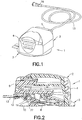
FIG. 1 is a perspective view of an infusion set and inserter in accordance with an exemplary embodiment of the present invention; -
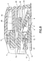
FIG. 2 is an elevational view in cross-section of the infusion set and inserter ofFIG. 1 ; -
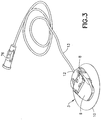
FIG. 3 is a perspective view of the infusion set ofFig. 1 after removal of the inserter; -
FIG. 4 is a lower perspective view of the infusion set without an adhesive patch and inserter ofFIG. 1 ; -
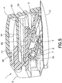
FIG. 5 is a perspective view in cross-section of the infusion set and inserter ofFig. 1 prior to activation; -
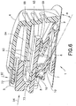
FIG. 6 is a perspective view in cross-section of the infusion set and inserter ofFIG. 1 prior to activation; -
FIG. 7 is a perspective view of the infusion set and inserter during activation; -
FIG. 8 is a perspective view in cross-section view of the infusion set and inserter ofFig. 1 during activation; -
FIG. 9 is a bottom plan view of the infusion set and inserter ofFIG. 1 during activation; -
FIG. 10 is a perspective view in cross-section of the infusion set and inserter after insertion of the cannula; -
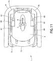
FIG. 11 is a bottom plan view of the infusion set and inserter ofFIG. 10 after insertion of the cannula; -
FIG. 12 is a perspective view of the infusion set ofFIG. 10 after removal of the inserter; -
FIG. 13 is a perspective view of an infusion set prior to exposure of the adhesive pad; -
FIG. 14 is an exploded perspective view of the infusion set ofFIG. 13 ; -
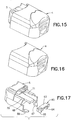
FIG. 15 is a perspective view of an inserter ofFIG. 1 ; -
FIG. 16 is a perspective view of a stationary member of the inserter ofFIG. 15 ; -
FIG. 17 is an exploded perspective view of a movable member of the inserter ofFIG. 15 ; -
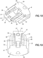
FIG. 18 is a perspective view of a slide of the infusion set ofFIG. 13 ; -
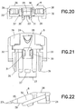
FIG. 19 is a top plan view of the slide ofFIG. 18 ; -
FIG. 20 is a front elevation view of the slide ofFIG. 18 ; -
FIG. 21 is a bottom plan view of the slide ofFIG. 18 ; -
FIG. 22 is a side elevational view of the slide ofFIG. 18 ; -
FIG. 23 is a rear elevational view of the slide ofFIG. 18 ; -
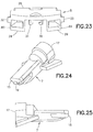
FIG. 24 is a perspective view of a hub of the infusion set ofFIG. 13 ; -
FIG. 25 is a side elevational view of the hub ofFIG. 24 ; -
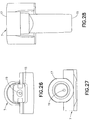
FIG. 26 is a front elevational view of the hub ofFIG. 24 ; -
FIG. 27 is a rear elevational view of the hub ofFIG. 24 ; -
FIG. 28 is a top plan view of the hub ofFIG. 24 ; -
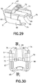
FIG. 29 is a perspective view of a movable member of the inserter ofFIG. 1 ; -
FIG. 30 is a top plan view of the movable member of the inserter ofFIG. 29 ; -
FIG. 31 is a rear elevational view of the movable member of the inserter ofFIG. 29 ; -
FIG. 32 is a side elevational view in cross-section of the movable member of the inserter ofFIG. 29 ; -
FIG. 33 is a bottom plan view of the movable member of the inserter ofFIG. 29 ; -
FIG. 34 is a side elevational view of the movable member of the inserter ofFIG. 29 ; -
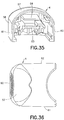
FIG. 35 is a perspective view of a stationary member of the inserter ofFIG. 1 ; -
FIG. 36 is a top plan view of the stationary member of the inserter ofFIG. 35 ; -
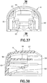
FIG. 37 is a rear elevational view of the stationary member of the inserter ofFIG. 35 ; -
FIG. 38 is a side elevational view in cross-section of the stationary member of the inserter ofFIG. 35 ; -
FIG. 39 is a bottom plan view of the stationary member of the inserter ofFIG. 35 ; -
FIG. 40 is a side elevational view of the stationary member of the inserter ofFIG. 35 ; -
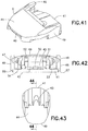
FIG. 41 is a perspective view of a base of the inserter ofFIG. 14 ; -
FIG. 42 is a rear elevational view of the base ofFIG. 41 ; -
FIG. 43 is a bottom plan view of the base ofFIG. 41 ; -
FIG. 44 is a side elevational view in cross-section of the base ofFIG. 41 ; -
FIG. 45 is a front elevational view of the base ofFIG. 41 ; -
FIG. 46 is a side elevational view of the base ofFIG. 41 ; -
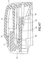
FIG. 47 is an elevational view in cross section of the inserter ofFIG. 1 ; -
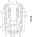
FIG. 48 is a bottom perspective view of the inserter ofFIG. 1 ; -
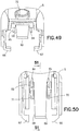
FIG. 49 is a rear perspective view of the movable member of the inserter ofFIG. 1 ; -
FIG. 50 is a bottom plan view of the movable member ofFIG. 49 ; -
FIG. 51 is an elevational view in cross section of the movable member ofFIG. 49 ; and -
FIG. 52 is a top plan view in cross section of a connector tab of the movable member engaging the infusion set slide member. - Throughout the drawings, like reference numerals will be understood to refer to like parts, components and structures.
- The exemplary embodiments of the present invention described below and shown in
FIGS. 1 - 52 provide a means of performing an intradermal needle insertion at an angle relative to a skin surface via a user motion in which the angle of user motion is different from the insertion angle of the needle. The insertion precisely targets the upper 3 mm of skin surface, and delivers insulin to the intradermal layers of skin via a standard insulin pump (not shown). - For example,
FIGS. 6 and10 illustrate an infusion setassembly 1 and motion to insert aneedle 6 via a user motion in a first direction (indicated byarrow 94 inFIGS. 6 and7 ) relative to a skin surface that is different from a second direction (indicated by the angle α inFIGS. 6 and7 ) of the inserted needle in accordance with an exemplary embodiment of the present invention.FIGS. 4 - 6 illustrate an infusion setassembly 1 in a free state before use.FIG. 10 illustrates the infusion setassembly 1 during insertion into the skin surface at an angle relative thereto via a user motion occurring at an angle to the skin surface that is different from the needle insertion angle, in accordance with an exemplary embodiment of the present invention. - An infusion set
assembly 1, as shown inFIG. 1 , includes aninserter 2 and aninfusion set 3. Theinserter 2 includes a fixedinserter member 4 and amovable inserter member 5 movably connected to the fixedinserter member 4. Themovable inserter member 5 is movable from a first position shown inFIG. 5 to a second position shown inFIG. 10 . The infusion set 3 includes arigid needle 6, ahub 7, amovable slide member 8 and a fixedbase member 9, as shown inFIG. 14 . An adhesive pad orpatch 10 secures thebase member 9 to the skin surface. Therigid needle 6 is fixedly connected to thehub 7, which is fixedly connected to theslide member 8. Theslide member 8 moves relative to the fixedbase member 9 from a first position in which theneedle 6 is not exposed externally of the infusion set 3 to a second position in which theneedle 6 is exposed externally of the infusion set 3. Anopening 11 in theadhesive pad 10 allows theneedle 6 to pass therethrough. Aconnector 12 connects tubing from an infusion pump (not shown) to the infusion set 3. - The
rigid needle 6 is preferably hollow to facilitate delivering medicament therethrough and is preferably made of 31 gauge stainless steel with a sharp beveled tip. An end port in a patient end of theneedle 6 allows the medicament to be delivered into the infusion site. A side port can be used in addition to or instead of the end port. An opening in the non-patient end of theneedle 6 receives medicament delivered from the insulin pump throughtubing 13. - The
hub 7, as shown inFIGS. 26 - 30 , fixedly receives theneedle 6, which can be secured thereto in any suitable manner, such as with an adhesive. A bore 19 in thehub 7 receives theneedle 6, which can be secured therein with an adhesive. Thepatient end 14 of theneedle 6 extends beyond afirst end 15 of thehub 7. Aseptum 16 is disposed in asecond end 17 of thehub 7 to seal the hub and prevent access to the opening in thenon-patient end 18 of theneedle 6. Theseptum 16 is preferably made of isoprene, but any suitable material can be used. Thehub 7 is preferably made of an injection-molded plastic, although any suitable material can be used. - The
slide member 8, as shown inFIGS. 18 - 23 , has afront end 23 and arear end 24. Anangled portion 25 of anupper surface 26 slopes upwardly from thefront end 23 toward therear end 24. Preferably, theangled portion 25 has an angle of between approximately ten (10) and forty-five degrees (45), inclusive. More preferably, the angled portion has an angle of approximately twenty (20) degrees. Anopening 27 is formed in theangled portion 25 of theupper surface 26. Acavity 28 is formed in alower surface 29 of theslide member 8 to receive thehub 7.Flex arms lower surface 29 proximal thecavity 28 to facilitate securing thehub 7 in thecavity 28. Preferably, thehub 7 is secured at an angle substantially similar to the angle of theangled portion 25.Outer rails slide member 8. Preferably, theouter rails angled portion 25.Snap arms outer rails Hooks snap arms arms outer rails snap arms Openings 80 and 81 in therear end 24 receiveconnector arms 78 and 79 (FIG. 14 ) to secure theconnector 12 thereto. Theslide member 8 is preferably made of an injection-molded plastic, such as PETG, but any suitable material can be used. - The
base member 9, as shown inFIGS. 41 - 46 , has afront end 40 and arear end 41. Alower surface 42 extends from thefront end 40 toward therear end 41. Anopening 43 in thelower surface 42 allows theneedle 6 to pass therethrough. Preferably, theopening 43 has a substantially oval shape. Anupper surface 44 extends rearwardly from thefront end 40 and defines acavity 45 between theupper surface 44 and thelower surface 42 for receiving theslide member 8.Outer channels side walls lower surface 42 and theupper surface 44. Alower tab 50 extends upwardly from thelower surface 42, as shown inFIG. 44 .Upper tabs upper surface 44, as shown inFIGS. 42 and44 .Inner channels upper tabs channels base member 9 is preferably made of an injection-molded plastic, such as PETG, but any suitable material can be used. - A pressure sensitive
adhesive pad 10 is connected to thelower surface 42 of thebase member 9, as shown inFIGS. 1 ,3 and14 . Anadhesive backing 55 is connected to theadhesive pad 10 to cover the adhesive pad prior to use. Theadhesive backing 55 has atab element 56 to facilitate separating the cover from theadhesive pad 10 to expose the adhesive pad when the adhesive pad is to be secured to an infusion site. The pressure sensitiveadhesive pad 10 can comprise any suitable material, such as an adhesive fabric. - The fixed
inserter member 4 has anupper surface 57 with awall 58 extending downwardly therefrom, as shown inFIGS. 35 - 40 . Theupper surface 57 and thewall 58 define acavity 59. Preferably, thewall 58 has afront wall 60 and opposingside walls cavity 59. Ashelf 63 disposed in thecavity 59 extends laterally between theside walls flexible beam 64 extends rearwardly from thefront wall 60 in thecavity 59. The fixedinserter member 4 is preferably made of an injection-molded plastic, such as acrylonitrile butadiene styrene (ABS), but any suitable material can be used. - The
movable inserter member 5 has arear wall 65 and opposingside walls FIGS. 29 - 34 . A latchingarm 68 extends forwardly from therear wall 65 and has atab 69 extending downwardly from a free end thereof.Slots arm 68. Aflexible member 72 is preferably connected to themovable inserter member 5 by a livinghinge 73, although any suitable means for connecting the flexible member can be used that allows deflection of the flexible member. Lockingfeet side walls movable inserter member 5 is preferably made of an injection-molded plastic, such as PETG, but any suitable material can be used. - The
connector 12 has flexibleplastic tubing 13 connected thereto for delivering medicament from the insulin pump (not shown) to the infusion set 3, as shown inFIG. 14 . Apump connector 76 is disposed at one of thetubing 13 for connecting to the insulin pump. Theconnector 12 is disposed at the other end of thetubing 13 for connecting to theslide member 8 of the infusion set 3. Thetubing 13 connects through arear surface 89 of theconnector 12. Aneedle 77 extends forwardly from theconnector 12 to pierce theseptum 16 disposed in thehub 7 when theconnector 12 is connected to theslide member 8. By piercing thehub septum 16, thehub needle 6 is fluidly connected to the insulin pump.Snap arms slide member 8 to secure theconnector 12 thereto. Moving thesnap arms connector 12 to be disconnected from the infusion set 3 as necessary. - A
connector tab 82, as shown inFIGS. 17 and48 - 51 , has abase 83 andlegs base 83. Thelegs connector tab 82 are received by theslots movable inserter member 5 such that thebase 83 is disposed above the latchingarm 68. Alternatively, theconnector tab 82 can be integrally formed with themovable inserter member 5 as a single piece. - The exemplary embodiments comprise an adhesive secured infusion set 3 and a
disposable inserter 2 for performing an intradermal needle insertion precisely targeting the upper 3 mm of skin surface. The infusion set 3 can be adhesively attached to a skin surface, and theinserter 2 can be used to angularly insert theneedle 6 into a desired insertion position. The insertion position of theneedle 6 is maintained by securing theslide member 8 to thebase member 9 to hold the insertedneedle 6 in position and prevent theslide member 8 and insertedneedle 6 from retraction once in the inserted position. - The infusion set
assembly 1 can include adisposable inserter 2, as shown inFIGS. 1 and 2 . Theinserter 2 can also be reusable if desired. Preferably, the infusion setassembly 1 is packaged such that the infusion set 3 is retained by theinserter 2. Alternatively, the infusion set 3 can be packaged without theinserter 2. Theneedle 6 is initially slightly recessed in the infusion set 6 to substantially prevent an accidental needle stick, but is visible from a bottom of the infusion set 2, as shown inFIG. 4 , so a user can visibly determine priming of the infusion set 3 prior to adhering the infusion set 3 to an infusion site. - The exemplary embodiments are configured to be efficient and user friendly. The user first peels off the
adhesive backing 55, revealing theadhesive pad 10 on thelower surface 42 of thebase member 9 of the infusion set 3. The infusion setassembly 1 can then be adhered to the infusion site with a downward pressure or application force by the user. The sliding action of the slidingbase member 5 angularly inserts theneedle 6, as described in greater detail below, into the upper 3 mm of skin surface, the intradermal space, to facilitate better drug absorption. After theneedle 6 has been inserted, theinserter 2 can be removed and properly disposed of. The user can disconnect and reconnect theconnector 12 as desired. - Prior to activation, the infusion set
slide member 8 and themovable inserter member 5 are locked in their first positions, as shown inFIGS. 4 - 6 . As noted above, theneedle 6 is recessed within and visible through theopenings adhesive pad 10 and thebase member 9, respectively, as shown inFIG. 4 , thereby preventing accidental needle sticks and allowing for visible priming of the infusion set 3. Thetab 69 of the latchingarm 68 of themovable inserter member 5 engages theshelf 63 of the fixedinserter member 4, as shown inFIGS. 5 ,47 and48 , thereby preventing the movable inserter member from being separated from the fixedinserter member 4. Additionally, prior to activation, theflexible beam 64 of the fixedinserter member 4 engagesribs 86 extending downwardly from theflexible member 72 of themovable inserter member 5, as shown inFIG. 47 , thereby preventing accidental activation of the infusion set 3. Accordingly, themovable inserter member 5 is prevented from being withdrawn from the fixedinserter member 4 in addition to being prevented from being moved into the fixed inserter member. - Additionally, the infusion set 3 is prevented from being removed from the
inserter 2 prior to activation, as shown inFIG. 4 . The lockingfeet movable inserter member 4 engage longitudinally extendingbase members 87 and 88 (FIG. 42 ), thereby preventing removal of theinserter 2 from infusion set 3 prior to fully inserting theneedle 6. Inwardly extending retainingribs rear surface 89 of theconnector 12 to prevent withdrawal of the infusion set 3 from theinserter 2 prior to activation. Accordingly, the infusion set 3 is retained by theinserter 2 prior to activation and until theneedle 6 is fully inserted. - The infusion set 3 is activated by moving the
flexible member 72 and squeezing theinserter 2 together, as shown inFIGS. 6 and7 . Pressing theflexible member 72 inwardly, in a direction indicated byarrow 92, causes theflexible member 72 to rotate about the livinghinge 73, thereby unlocking theinserter 2. Theflexible member 72 engages and moves theflexible beam 64 of the fixedinserter member 4 downwardly (indicated byarrow 93 inFIG. 6 ), thereby allowing theflexible member 72 of themovable inserter member 5 to slide into the fixed inserter member 4 (indicated byarrow 94 inFIG. 7 ). - When the
movable inserter member 5 slides into the fixedinserter member 5, as shown inFIG. 8 , themovable inserter member 5 pushes the rear surface of theconnector 12. As shown inFIG. 9 , the inwardly extending retainingribs movable inserter member 5 engage and push theconnector 12 in a forward direction. Theconnector 12 is connected to the infusion setslide member 8, such that theslide member 8 moves forwardly with forward movement of theconnector 12. Theslide member 9 moves into the infusion setbase member 9, thereby inserting theneedle 6 into the dermis layer. As shown inFIG. 8 , themovable inserter member 5 is partially inserted in the fixedinserter member 4 such that the needle is partially inserted. The lockingfeet movable inserter member 5 still engage the longitudinally extendingbase member inserter member 9, as shown inFIG. 9 , such that theinserter 2 cannot yet be removed from the infusion set 3. Accordingly, theinserter 2 is prevented from being removed from the infusion set 3 until theneedle 6 is fully inserted, thereby preventing the user from inadvertently inserting theneedle 6 only partially. - Additionally, the
legs connector tab 82, as shown inFIGS. 17 and48 - 52 , engage arear end 24 of theslide member 8, thereby further facilitate forward movement of theslide member 8 with forward movement of themovable inserter member 5 to which theconnector tab 82 is connected. - As shown in
FIGS. 8 and9 , the forward movement of themovable inserter member 5 causes theconnector 12 to move forwardly, which causes the movement of the infusion setslide member 8 toward the fully inserted second position. Theouter rails 32 and 33 (FIGS. 18 - 23 ) are guided by theouter channels 46 and 47 (FIGS. 41, 42 and44 ) in the infusion set fixedmember 9. Theouter channels slide member 8 forwardly at an angle α (FIGS. 6 and44 ) relative to the skin surface. Preferably, the angle α is between approximately ten (10) and forty-five (45) degrees, inclusive. More preferably, the angle α is approximately twenty (20) degrees. Theneedle 6 is preferably aligned with the angular insertion direction of theslide member 8 such that the needle is inserted in the substantially axial direction of thehub 7. Alternatively, theneedle 6 can be offset from the insertion angle α such that the insertion direction of theneedle 6 includes both axial and radial components with respect to thehub 7. In such a configuration, the orientation angle of theneedle 6 is offset from the insertion slide angle of theslide member 8 and thehub 7. - Forward movement of the infusion set
slide member 8 is stopped when thestop arms inner channels base member 9. The forward movement of theconnector 12 and themovable inserter member 5 is also stopped by stopping the forward movement of theslide member 8. The infusion set 3 is now fully activated and theneedle 6 is fully inserted at the angle α in the infusion site, as shown inFIGS. 10 - 12 . Theslide member 8 and themovable inserter member 5 are now in the second position. Theopening 27 in theslide member 8 receives thelower tab 50 of thebase member 9 when theslide member 8 moves into the second position, as shown inFIG. 10 , thereby locking theslide member 8 to thebase member 9 to prevent accidental removal of the insertedneedle 6. Additionally, thehooks snap arms slide member 8 engage theupper tabs upper surface 44 of thebase member 9 to further secure theslide member 8 to thebase member 9. - Now that the
movable inserter member 5 has reached the second position, as shown inFIG. 11 , the lockingfeet movable inserter member 4 have moved past the longitudinally extendingbase members rear portions feet rear portions base members inserter 2 until theneedle 6 is fully inserted. Therear portions feet rear portions base members feet base members inserter 2 can now be removed from the infusion set 3 by lifting the inserter upwardly with respect to the infusion set 3 and be properly disposed of. Theconnector 12 can be removed and connected to theslide member 8 as desired. Theslide member 8 is permanently locked to thebase member 9, as described above, thereby maintaining theneedle 6 in its intradermally injected position until theset 3 is removed by the user. - The angular insertion of the
needle 6 provides a solid anchor that maintains the infusion site. Typically, it is very difficult to maintain the position of short (i.e., 1 - 3 mm) needles within the skin. However, by angularly inserting theneedle 6, the skin itself provides a vertical retention force. Accordingly, the insertedneedle 6 is secured both vertically and horizontally. Furthermore, the angled insertion allows for more flexibility of needle or cannula choice for infusion by reducing the vertical height of the cannula opening. Also, because theneedle 6 is inserted at an angle, a longer needle and/or needle opening can be used than those provided for a non-angled insertion to target the same intradermal depth. - By first adhering the infusion set
assembly 1 to the skin surface, a precise mechanical foundation is provided which ensures that the needle angle, skin tensioning, stretching and/or flattening, and insertion depth are consistent. Further, in doing so, tenting is also reduced or eliminated. Still further, by isolating the needle site from the pump connection, vibrations and movements are reduced. In addition, a low-profile is provided which further isolates theneedle 6 from any external forces. - By infusing into the intradermal layer of the skin, the exemplary embodiments of the present invention offer the potential for better absorption of insulin when compared to subcutaneous delivery systems. In doing so, it may be possible for the typical user to both consume less insulin and maintain a better medicament regime. It will be appreciated that multiple needles or microneedles can be used, if desired, in place of a single needle or microneedle.
- Proper alignment is accomplished by providing a solid, fixed foundation for the user to slide the
movable inserter member 5 to angularly insert theneedle 6. Such a solid, fixed foundation is provided by theadhesive layer 10. The skin adhesive layer secures the infusion set 3 at a desired orientation, such that theneedle hub 7 andneedle 6 are at a desired orientation of use, and the user is substantially prevented from holding the infusion set 3 at various angles to the insertion site. Accordingly, precise, repeatable insertions are accomplished. - Furthermore, the angle of the needle hub can be changed in this or other exemplary embodiments of the present invention to affect the insertion angle and final placement of the needle. As shown in
FIG. 6 , theneedle 6 is aligned with the direction of travel of thehub 7. Alternatively, theneedle 6 can be offset from the direction of travel of thehub 7. - Still further, in accordance with another exemplary embodiment of the present invention, the infusion set 3 can be activated without the
inserter 2. The insertion is fully integrated into the infusion set 3 such that the user does not have to carry the inserter or load the infusion set into the inserter. The integrated system allows the user more freedom from carrying theinserter 2. Such a system and method is economical, simple, and compact, and provides a system of insertion that is integrated with the device. Therefore, a user can correctly insert the device withoutinserter 2. - Although the previously-described embodiments relate to intradermal infusion sets, the principles of the present invention are also applicable to other types of infusion sets, for example, subcutaneous infusion sets in which the patient cannula consists of a soft plastic catheter that is inserted with the aid of a rigid metal introducer needle.
- Although only a few exemplary embodiments of the present invention have been described in detail above, those skilled in the art will readily appreciate that many modifications are possible in the exemplary embodiments without materially departing from the novel teachings and advantages of this invention. Accordingly, all such modifications are intended to be included within the scope of this invention as defined in the appended claims and their equivalents.
Claims (18)
- An infusion set (3) adapted to be secured to a skin surface, comprising:a fixed base member (9) connectable to the skin surface;a movable slide member (8) located inside the fixed base member (9) having a needle or cannula (6) connected thereto and movable relative to said fixed base member (9), to insert the needle or cannula at an angle relative to a skin surface via a user motion, the angle of user motion being different from the angle of the inserted needle or cannula, to target and deliver insulin or other medicament to the upper 3 mm of skin surface,said movable slide member (8) being movable from a first position in which said needle or cannula (6) is not exposed externally of said fixed base member (9) to a second position in which said needle or cannula (6) is exposed externally of said fixed base member (9),said movable slide member (8) being locked to said fixed base member (9) in said second position; andsaid fixed base member (9) comprising longitudinally extending base members (87,88) for engaging locking feet (74,75) of an inserter (2) according to claim 5 to prevent removal of said inserter (2) from said fixed base member (9) when said moveable slide member (8) is in said first position and to allow said inserter (2) to be released from said fixed base member (9) when said moveable slide member (8) reaches said second position and said locking feet (74,75) extend past and are clear of said longitudinally extending base members (87,88).
- The infusion set (3) according to claim 1, wherein said movable slide member (8) moves in a direction not parallel to the skin surface and/or said needle (6) is offset from said moving direction of said slide member (8).
- The infusion set (3) according to claim 1, wherein said needle or cannula (6) is aligned with said moving direction of said slide member (8) wherein preferably a tab (50) on said base member (9) is received by an opening (27) in said slide member (8) when said slide member (8) is in said second position, thereby locking said slide member (8) to said base member (9).
- The infusion set (3) according to claim 1, wherein said needle or cannula (6) is disposed at an angle of approximately 20 degrees relative to the skin surface and/or wherein said needle or cannula (6) is disposed at an angle between approximately 10 and 45 degrees, inclusive, relative to the skin surface.
- An inserter (2) for inserting a needle or cannula (6) of an infusion set (3) according to claim 1,
comprising:a fixed inserter member (4);a movable inserter member (5) movably connected to said fixed inserter member (4) and adapted to receive the infusion set (3),said movable inserter member (5) being movable from a first position to a second position to expose the needle or cannula (6), the movable inserter member (5) being locked to the fixed inserter member (4) in the first position to prevent accidentally exposing the needle or cannula (6); andsaid moveable inserter member (5) comprising locking feet (74,75) for engaging longitudinally extending base members (87,88) of an infusion set to prevent removal of said moveable inserter member (5) from said infusion set (3) when said moveable inserter member (5) is in said first position and to allow said moveable inserter member (5) to be released from said infusion set (3) when said moveable inserter member (5) reaches said second position and said locking feet (74,75) extend past and are clear of said longitudinally extending base members (87,88). - The inserter (2) according to claim 5, wherein a flexible beam (64) of said fixed inserter member (4) engages said movable inserter member (5) to prevent movement of said movable inserter member (5) from said first position to said second position.
- The inserter (2) according to claim 6, wherein a flexible member (72) of said movable inserter member (5) is moved to deflect said flexible beam (64) of said fixed inserter member (4), thereby disengaging said flexible beam (64) from said fixed inserter member (4) to allow movement of said movable inserter member (5) from said first position to said second position.
- The inserter (2) according to claim 5, wherein a latching arm (68) of said movable inserter member (5) is connected to said fixed inserter member (4) to prevent separation of said movable inserter member (5) from said fixed inserter member (4).
- The inserter (2) according to claim 5, wherein movable inserter member (5) is only separatable from the received infusion set (3) when the movable inserter member (5) is in said second position.
- An infusion set assembly (1) adapted to be secured to a skin surface, comprising:an infusion set (3) including a fixed base member (9) having longitudinally extending base members (87,88), said fixed base member (9) connectable to the skin surface;a movable slide member (8) located inside the fixed base member (9) having a needle or cannula (6) connected thereto and movable relative to said fixed base member (9),said movable slide member (8) being movable from a first position in which said needle or cannula (6) is not exposed externally of said fixed base member (9) to a second position in which said needle or cannula (6) is exposed externally of said fixed base member (9); andan inserter (2) comprising locking feet (74,75) and connected to said infusion set for moving said movable slide member (8) from said first position to said second position and being prevented from removal from said infusion set (3) when said slide member (8) is in said first position and said locking feet (74,75) engage said longitudinally extending base members (87,88), and being allowed to be released from said infusion set (3) when said slide member (8) reaches said second position and said locking feet (74,75) extend past and are clear of said longitudinally extending base members (87,88).
- The infusion set assembly (1) according to claim 10, wherein said inserter (2) is prevented from being removed from said infusion set (3) until said movable slide member (8) is in said second position and/or wherein said inserter (2) includes a movable inserter member (5) and a fixed inserter member (4).
- The infusion set assembly (1) according to claim 11, wherein said movable inserter member (5) is removably connected to said fixed base member (9).
- The infusion set assembly (1) according to claim 12, wherein said movable inserter member (5) is movable from a first position to a second position that moves said movable slide member (8) from said first position to said second position, said movable inserter member (5) being substantially prevented from accidentally moving from said first position to said second position.
- The infusion set assembly (1) according to claim 13, wherein a flexible beam (64) of said fixed inserter member (4) engages a rib (86) of said movable inserter member (5) to prevent said movable inserter member (5) from moving from said first position to said second position.
- The infusion set assembly (1) according to claim 14, wherein a flexible member (68) of said movable inserter member (5) is moved to deflect said flexible beam (64) of said fixed inserter member (4), thereby disengaging said flexible beam (64) from said rib (86) of said fixed inserter member (4) and allowing said movable inserter member (5) to move from said first position to said second position.
- The infusion set assembly (1) according to claim 15, wherein said needle or cannula (6) is disposed at an angle of approximately 20 degrees relative to the skin surface and/or wherein said needle or cannula (6) is disposed at an angle between approximately 10 and 45 degrees, inclusive, relative to the skin surface.
- The infusion set assembly (1) according to claim 11, wherein a latch arm (68) of said movable inserter member (5) engages said fixed inserter member (4) to prevent separation of said movable inserter member (5) from said fixed inserter member (4).
- The infusion set assembly (1) according to claim 11, wherein said movable slide member (8) moves from said first position to said second position in a first direction, and said movable inserter member (8) moves from said first position to said second position in a second direction different from said first direction.
Priority Applications (1)
| Application Number | Priority Date | Filing Date | Title |
|---|---|---|---|
| EP17184762.7A EP3263157B1 (en) | 2012-09-27 | 2013-09-25 | Angled inserter for drug infusion |
Applications Claiming Priority (1)
| Application Number | Priority Date | Filing Date | Title |
|---|---|---|---|
| US13/629,479 US9782538B2 (en) | 2012-09-27 | 2012-09-27 | Angled inserter for drug infusion |
Related Child Applications (1)
| Application Number | Title | Priority Date | Filing Date |
|---|---|---|---|
| EP17184762.7A Division EP3263157B1 (en) | 2012-09-27 | 2013-09-25 | Angled inserter for drug infusion |
Publications (2)
| Publication Number | Publication Date |
|---|---|
| EP2712641A1 EP2712641A1 (en) | 2014-04-02 |
| EP2712641B1 true EP2712641B1 (en) | 2017-08-09 |
Family
ID=49328320
Family Applications (2)
| Application Number | Title | Priority Date | Filing Date |
|---|---|---|---|
| EP13185981.1A Active EP2712641B1 (en) | 2012-09-27 | 2013-09-25 | Angled inserter for drug infusion |
| EP17184762.7A Active EP3263157B1 (en) | 2012-09-27 | 2013-09-25 | Angled inserter for drug infusion |
Family Applications After (1)
| Application Number | Title | Priority Date | Filing Date |
|---|---|---|---|
| EP17184762.7A Active EP3263157B1 (en) | 2012-09-27 | 2013-09-25 | Angled inserter for drug infusion |
Country Status (6)
| Country | Link |
|---|---|
| US (2) | US9782538B2 (en) |
| EP (2) | EP2712641B1 (en) |
| JP (2) | JP6334120B2 (en) |
| CN (1) | CN203694220U (en) |
| CA (2) | CA3130724C (en) |
| ES (2) | ES2646589T3 (en) |
Families Citing this family (29)
| Publication number | Priority date | Publication date | Assignee | Title |
|---|---|---|---|---|
| ATE480278T1 (en) | 2005-09-12 | 2010-09-15 | Unomedical As | INTRODUCTION SYSTEM FOR AN INFUSION SET WITH A FIRST AND SECOND SPRING UNIT |
| EP2552513B1 (en) | 2010-03-30 | 2014-03-19 | Unomedical A/S | Medical device |
| US10194938B2 (en) | 2011-03-14 | 2019-02-05 | UnoMedical, AS | Inserter system with transport protection |
| CN103957962B (en) | 2011-10-05 | 2017-07-07 | 犹诺医药有限公司 | Insert for inserting multiple percutaneous parts simultaneously |
| EP2583715A1 (en) | 2011-10-19 | 2013-04-24 | Unomedical A/S | Infusion tube system and method for manufacture |
| ES2759522T3 (en) | 2011-12-07 | 2020-05-11 | Becton Dickinson Co | Infusion set with removable fluid connector |
| ES2689848T3 (en) | 2011-12-07 | 2018-11-16 | Becton, Dickinson And Company | Needle protection sets and infusion devices for use with them |
| USD754842S1 (en) * | 2012-12-07 | 2016-04-26 | Becton, Dickinson And Company | Infusion set needle guard |
| USD747457S1 (en) * | 2012-12-07 | 2016-01-12 | Becton, Dickinson And Company | Infusion set needle guard |
| USD756504S1 (en) * | 2012-12-07 | 2016-05-17 | Becton, Dickinson And Company | Infusion set base |
| USD747458S1 (en) * | 2012-12-07 | 2016-01-12 | Becton, Dickinson And Company | Infusion set insertion needle assembly |
| USD754843S1 (en) * | 2012-12-07 | 2016-04-26 | Becton, Dickinson And Company | Infusion set assembly |
| USD747456S1 (en) * | 2012-12-07 | 2016-01-12 | Becton, Dickinson And Company | Infusion set assembly |
| USD747459S1 (en) * | 2012-12-07 | 2016-01-12 | Becton, Dickinson And Company | Infusion set assembly |
| US10080839B2 (en) * | 2013-03-14 | 2018-09-25 | Becton, Dickinson And Company | Angled inserter for drug infusion |
| SG11201609963PA (en) | 2014-06-03 | 2016-12-29 | Amgen Inc | Devices and methods for assisting a user of a drug delivery device |
| JP2017538512A (en) | 2014-12-19 | 2017-12-28 | アムジエン・インコーポレーテツド | Drug delivery device including live button or user interface field |
| US10799630B2 (en) | 2014-12-19 | 2020-10-13 | Amgen Inc. | Drug delivery device with proximity sensor |
| WO2017125817A1 (en) | 2016-01-19 | 2017-07-27 | Unomedical A/S | Cannula and infusion devices |
| EP3760274B1 (en) * | 2016-05-26 | 2023-05-31 | Medtronic Minimed, Inc. | Systems for set connector assembly with lock |
| EP3260151A1 (en) * | 2016-06-23 | 2017-12-27 | TecPharma Licensing AG | A needle insertion and retraction mechanism for a medication delivery device |
| USD813380S1 (en) * | 2016-08-05 | 2018-03-20 | Amgen Inc. | On-body injector |
| WO2018184012A1 (en) | 2017-03-31 | 2018-10-04 | Capillary Biomedical, Inc. | Helical insertion infusion device |
| JP2019205792A (en) * | 2018-05-30 | 2019-12-05 | 大成化工株式会社 | Intracutaneous injection aid |
| US11213665B2 (en) * | 2018-06-15 | 2022-01-04 | Esthetic Education LLC | Angled microneedle cartridge |
| CN116983507A (en) | 2019-02-22 | 2023-11-03 | 德卡产品有限公司 | Infusion set and insert assembly systems and methods |
| US11458292B2 (en) | 2019-05-20 | 2022-10-04 | Unomedical A/S | Rotatable infusion device and methods thereof |
| KR20240019809A (en) * | 2021-06-11 | 2024-02-14 | 브리스톨-마이어스 스큅 컴퍼니 | Drug cartridge, drug delivery device, and method of preparing the same |
| USD1013864S1 (en) | 2021-08-26 | 2024-02-06 | Deka Products Limited Partnership | Fluid administration apparatus assembly |
Family Cites Families (28)
| Publication number | Priority date | Publication date | Assignee | Title |
|---|---|---|---|---|
| US5688254A (en) | 1983-01-24 | 1997-11-18 | Icu Medical, Inc. | Medical connector |
| US5545143A (en) | 1993-01-21 | 1996-08-13 | T. S. I. Medical | Device for subcutaneous medication delivery |
| DK25793A (en) | 1993-03-09 | 1994-09-10 | Pharma Plast Int As | Infusion set for intermittent or continuous administration of a therapeutic agent |
| US5545152A (en) | 1994-10-28 | 1996-08-13 | Minimed Inc. | Quick-connect coupling for a medication infusion system |
| US6607509B2 (en) | 1997-12-31 | 2003-08-19 | Medtronic Minimed, Inc. | Insertion device for an insertion set and method of using the same |
| US7329239B2 (en) | 1997-02-05 | 2008-02-12 | Medtronic Minimed, Inc. | Insertion device for an insertion set and method of using the same |
| CA2484271C (en) | 1997-12-31 | 2007-04-24 | Medtronic Minimed, Inc. | Insertion device for an insertion set and method of using the same |
| US6123690A (en) | 1998-03-20 | 2000-09-26 | Maersk Medical A/S | Subcutaneous infusion device |
| US5980506A (en) | 1998-03-20 | 1999-11-09 | Mathiasen; Orla | Subcutaneous infusion device |
| US6086575A (en) | 1998-03-20 | 2000-07-11 | Maersk Medical A/S | Subcutaneous infusion device |
| DE10004496A1 (en) | 2000-02-02 | 2000-08-03 | Meonic Sys Eng Gmbh | Injection of medicament e.g. insulin, involves sampling of medical data relating to patient's condition, storing and comparing in data processing unit, and using result as control signal for injection dosing/timing unit |
| US7052483B2 (en) * | 2000-12-19 | 2006-05-30 | Animas Corporation | Transcutaneous inserter for low-profile infusion sets |
| US6830562B2 (en) * | 2001-09-27 | 2004-12-14 | Unomedical A/S | Injector device for placing a subcutaneous infusion set |
| US7429258B2 (en) | 2001-10-26 | 2008-09-30 | Massachusetts Institute Of Technology | Microneedle transport device |
| US20090012472A1 (en) | 2004-09-22 | 2009-01-08 | Novo Nordisk A/S | Medical Device with Cannula Inserter |
| US7303543B1 (en) | 2004-12-03 | 2007-12-04 | Medtronic Minimed, Inc. | Medication infusion set |
| US20060184104A1 (en) | 2005-02-15 | 2006-08-17 | Medtronic Minimed, Inc. | Needle guard |
| EP1877116A1 (en) * | 2005-04-13 | 2008-01-16 | Novo Nordisk A/S | Medical skin mountable device and system |
| DK1968677T3 (en) | 2005-09-15 | 2019-07-15 | Hoffmann La Roche | Insertion head with needle guard in the handle |
| US20070282269A1 (en) | 2006-05-31 | 2007-12-06 | Seattle Medical Technologies | Cannula delivery apparatus and method for a disposable infusion device |
| CN101460207B (en) | 2006-06-06 | 2012-03-21 | 诺沃-诺迪斯克有限公司 | Assembly comprising skin-mountable device and packaging therefore |
| EP2054109B1 (en) | 2006-08-24 | 2017-12-13 | F. Hoffmann-La Roche AG | Insertion device for insertion heads, in particular for infusion sets |
| US20080167620A1 (en) | 2007-01-09 | 2008-07-10 | Seattle Medical Technologies | Disposable infusion device facilitating tissue fold formation for cannula deployment and method |
| GB2445437B (en) | 2007-07-06 | 2008-11-26 | Applied Medical Technology Ltd | Cannula insertion device |
| AU2008281383A1 (en) | 2007-08-01 | 2009-02-05 | F.Hoffmann-La Roche Ag | Device for facilitating infusion of therapeutic fluids and sensing of bodily analytes |
| US10076606B2 (en) * | 2007-12-10 | 2018-09-18 | Medtronic Minimed, Inc. | Insertion devices, insertion needles, and related methods |
| DK2327433T3 (en) | 2009-11-26 | 2012-07-23 | Hoffmann La Roche | Externally releasable needle device |
| US9950109B2 (en) | 2010-11-30 | 2018-04-24 | Becton, Dickinson And Company | Slide-activated angled inserter and cantilevered ballistic insertion for intradermal drug infusion |
-
2012
- 2012-09-27 US US13/629,479 patent/US9782538B2/en active Active
-
2013
- 2013-09-23 CA CA3130724A patent/CA3130724C/en active Active
- 2013-09-23 CA CA2827953A patent/CA2827953C/en active Active
- 2013-09-25 ES ES13185981.1T patent/ES2646589T3/en active Active
- 2013-09-25 EP EP13185981.1A patent/EP2712641B1/en active Active
- 2013-09-25 EP EP17184762.7A patent/EP3263157B1/en active Active
- 2013-09-25 ES ES17184762T patent/ES2847848T3/en active Active
- 2013-09-27 CN CN201320896801.1U patent/CN203694220U/en not_active Expired - Lifetime
- 2013-09-27 JP JP2013201686A patent/JP6334120B2/en active Active
-
2017
- 2017-09-08 US US15/699,235 patent/US10729844B2/en active Active
-
2018
- 2018-04-26 JP JP2018085449A patent/JP2018114339A/en active Pending
Non-Patent Citations (1)
| Title |
|---|
| None * |
Also Published As
| Publication number | Publication date |
|---|---|
| US20170368257A1 (en) | 2017-12-28 |
| CN203694220U (en) | 2014-07-09 |
| CA3130724C (en) | 2023-08-22 |
| JP2018114339A (en) | 2018-07-26 |
| US20140088549A1 (en) | 2014-03-27 |
| EP2712641A1 (en) | 2014-04-02 |
| US10729844B2 (en) | 2020-08-04 |
| CA3130724A1 (en) | 2014-03-27 |
| EP3263157B1 (en) | 2020-11-11 |
| CA2827953C (en) | 2021-11-02 |
| JP6334120B2 (en) | 2018-05-30 |
| JP2014069084A (en) | 2014-04-21 |
| CA2827953A1 (en) | 2014-03-27 |
| ES2646589T3 (en) | 2017-12-14 |
| EP3263157A1 (en) | 2018-01-03 |
| ES2847848T3 (en) | 2021-08-04 |
| US9782538B2 (en) | 2017-10-10 |
Similar Documents
| Publication | Publication Date | Title |
|---|---|---|
| US10729844B2 (en) | Angled inserter for drug infusion | |
| US10729845B2 (en) | Angled inserter for drug infusion | |
| EP2968891B1 (en) | Automatic angled infusion set assembly | |
| US10413660B2 (en) | Perpendicular infusion set and disposable inserter | |
| EP3167922A1 (en) | Slide-activated angled inserter and cantilevered ballistic insertion for intradermal drug infusion |
Legal Events
| Date | Code | Title | Description |
|---|---|---|---|
| PUAI | Public reference made under article 153(3) epc to a published international application that has entered the european phase |
Free format text: ORIGINAL CODE: 0009012 |
|
| AK | Designated contracting states |
Kind code of ref document: A1 Designated state(s): AL AT BE BG CH CY CZ DE DK EE ES FI FR GB GR HR HU IE IS IT LI LT LU LV MC MK MT NL NO PL PT RO RS SE SI SK SM TR |
|
| AX | Request for extension of the european patent |
Extension state: BA ME |
|
| 17P | Request for examination filed |
Effective date: 20141001 |
|
| RBV | Designated contracting states (corrected) |
Designated state(s): AL AT BE BG CH CY CZ DE DK EE ES FI FR GB GR HR HU IE IS IT LI LT LU LV MC MK MT NL NO PL PT RO RS SE SI SK SM TR |
|
| 17Q | First examination report despatched |
Effective date: 20150225 |
|
| RAP1 | Party data changed (applicant data changed or rights of an application transferred) |
Owner name: BECTON, DICKINSON AND COMPANY |
|
| GRAP | Despatch of communication of intention to grant a patent |
Free format text: ORIGINAL CODE: EPIDOSNIGR1 |
|
| INTG | Intention to grant announced |
Effective date: 20170221 |
|
| GRAS | Grant fee paid |
Free format text: ORIGINAL CODE: EPIDOSNIGR3 |
|
| GRAA | (expected) grant |
Free format text: ORIGINAL CODE: 0009210 |
|
| AK | Designated contracting states |
Kind code of ref document: B1 Designated state(s): AL AT BE BG CH CY CZ DE DK EE ES FI FR GB GR HR HU IE IS IT LI LT LU LV MC MK MT NL NO PL PT RO RS SE SI SK SM TR |
|
| REG | Reference to a national code |
Ref country code: GB Ref legal event code: FG4D |
|
| REG | Reference to a national code |
Ref country code: CH Ref legal event code: EP Ref country code: AT Ref legal event code: REF Ref document number: 916136 Country of ref document: AT Kind code of ref document: T Effective date: 20170815 |
|
| REG | Reference to a national code |
Ref country code: IE Ref legal event code: FG4D |
|
| REG | Reference to a national code |
Ref country code: DE Ref legal event code: R096 Ref document number: 602013024673 Country of ref document: DE Ref country code: FR Ref legal event code: PLFP Year of fee payment: 5 |
|
| REG | Reference to a national code |
Ref country code: NL Ref legal event code: MP Effective date: 20170809 |
|
| REG | Reference to a national code |
Ref country code: ES Ref legal event code: FG2A Ref document number: 2646589 Country of ref document: ES Kind code of ref document: T3 Effective date: 20171214 |
|
| REG | Reference to a national code |
Ref country code: LT Ref legal event code: MG4D |
|
| REG | Reference to a national code |
Ref country code: AT Ref legal event code: MK05 Ref document number: 916136 Country of ref document: AT Kind code of ref document: T Effective date: 20170809 |
|
| PG25 | Lapsed in a contracting state [announced via postgrant information from national office to epo] |
Ref country code: NL Free format text: LAPSE BECAUSE OF FAILURE TO SUBMIT A TRANSLATION OF THE DESCRIPTION OR TO PAY THE FEE WITHIN THE PRESCRIBED TIME-LIMIT Effective date: 20170809 Ref country code: HR Free format text: LAPSE BECAUSE OF FAILURE TO SUBMIT A TRANSLATION OF THE DESCRIPTION OR TO PAY THE FEE WITHIN THE PRESCRIBED TIME-LIMIT Effective date: 20170809 Ref country code: LT Free format text: LAPSE BECAUSE OF FAILURE TO SUBMIT A TRANSLATION OF THE DESCRIPTION OR TO PAY THE FEE WITHIN THE PRESCRIBED TIME-LIMIT Effective date: 20170809 Ref country code: AT Free format text: LAPSE BECAUSE OF FAILURE TO SUBMIT A TRANSLATION OF THE DESCRIPTION OR TO PAY THE FEE WITHIN THE PRESCRIBED TIME-LIMIT Effective date: 20170809 Ref country code: FI Free format text: LAPSE BECAUSE OF FAILURE TO SUBMIT A TRANSLATION OF THE DESCRIPTION OR TO PAY THE FEE WITHIN THE PRESCRIBED TIME-LIMIT Effective date: 20170809 Ref country code: SE Free format text: LAPSE BECAUSE OF FAILURE TO SUBMIT A TRANSLATION OF THE DESCRIPTION OR TO PAY THE FEE WITHIN THE PRESCRIBED TIME-LIMIT Effective date: 20170809 Ref country code: NO Free format text: LAPSE BECAUSE OF FAILURE TO SUBMIT A TRANSLATION OF THE DESCRIPTION OR TO PAY THE FEE WITHIN THE PRESCRIBED TIME-LIMIT Effective date: 20171109 |
|
| PG25 | Lapsed in a contracting state [announced via postgrant information from national office to epo] |
Ref country code: IS Free format text: LAPSE BECAUSE OF FAILURE TO SUBMIT A TRANSLATION OF THE DESCRIPTION OR TO PAY THE FEE WITHIN THE PRESCRIBED TIME-LIMIT Effective date: 20171209 Ref country code: RS Free format text: LAPSE BECAUSE OF FAILURE TO SUBMIT A TRANSLATION OF THE DESCRIPTION OR TO PAY THE FEE WITHIN THE PRESCRIBED TIME-LIMIT Effective date: 20170809 Ref country code: BG Free format text: LAPSE BECAUSE OF FAILURE TO SUBMIT A TRANSLATION OF THE DESCRIPTION OR TO PAY THE FEE WITHIN THE PRESCRIBED TIME-LIMIT Effective date: 20171109 Ref country code: LV Free format text: LAPSE BECAUSE OF FAILURE TO SUBMIT A TRANSLATION OF THE DESCRIPTION OR TO PAY THE FEE WITHIN THE PRESCRIBED TIME-LIMIT Effective date: 20170809 Ref country code: GR Free format text: LAPSE BECAUSE OF FAILURE TO SUBMIT A TRANSLATION OF THE DESCRIPTION OR TO PAY THE FEE WITHIN THE PRESCRIBED TIME-LIMIT Effective date: 20171110 Ref country code: PL Free format text: LAPSE BECAUSE OF FAILURE TO SUBMIT A TRANSLATION OF THE DESCRIPTION OR TO PAY THE FEE WITHIN THE PRESCRIBED TIME-LIMIT Effective date: 20170809 |
|
| PG25 | Lapsed in a contracting state [announced via postgrant information from national office to epo] |
Ref country code: RO Free format text: LAPSE BECAUSE OF FAILURE TO SUBMIT A TRANSLATION OF THE DESCRIPTION OR TO PAY THE FEE WITHIN THE PRESCRIBED TIME-LIMIT Effective date: 20170809 Ref country code: CZ Free format text: LAPSE BECAUSE OF FAILURE TO SUBMIT A TRANSLATION OF THE DESCRIPTION OR TO PAY THE FEE WITHIN THE PRESCRIBED TIME-LIMIT Effective date: 20170809 Ref country code: DK Free format text: LAPSE BECAUSE OF FAILURE TO SUBMIT A TRANSLATION OF THE DESCRIPTION OR TO PAY THE FEE WITHIN THE PRESCRIBED TIME-LIMIT Effective date: 20170809 |
|
| REG | Reference to a national code |
Ref country code: CH Ref legal event code: PL |
|
| REG | Reference to a national code |
Ref country code: DE Ref legal event code: R097 Ref document number: 602013024673 Country of ref document: DE |
|
| PG25 | Lapsed in a contracting state [announced via postgrant information from national office to epo] |
Ref country code: EE Free format text: LAPSE BECAUSE OF FAILURE TO SUBMIT A TRANSLATION OF THE DESCRIPTION OR TO PAY THE FEE WITHIN THE PRESCRIBED TIME-LIMIT Effective date: 20170809 Ref country code: MC Free format text: LAPSE BECAUSE OF FAILURE TO SUBMIT A TRANSLATION OF THE DESCRIPTION OR TO PAY THE FEE WITHIN THE PRESCRIBED TIME-LIMIT Effective date: 20170809 Ref country code: SK Free format text: LAPSE BECAUSE OF FAILURE TO SUBMIT A TRANSLATION OF THE DESCRIPTION OR TO PAY THE FEE WITHIN THE PRESCRIBED TIME-LIMIT Effective date: 20170809 Ref country code: SM Free format text: LAPSE BECAUSE OF FAILURE TO SUBMIT A TRANSLATION OF THE DESCRIPTION OR TO PAY THE FEE WITHIN THE PRESCRIBED TIME-LIMIT Effective date: 20170809 |
|
| PLBE | No opposition filed within time limit |
Free format text: ORIGINAL CODE: 0009261 |
|
| STAA | Information on the status of an ep patent application or granted ep patent |
Free format text: STATUS: NO OPPOSITION FILED WITHIN TIME LIMIT |
|
| REG | Reference to a national code |
Ref country code: IE Ref legal event code: MM4A |
|
| REG | Reference to a national code |
Ref country code: BE Ref legal event code: MM Effective date: 20170930 |
|
| PG25 | Lapsed in a contracting state [announced via postgrant information from national office to epo] |
Ref country code: LU Free format text: LAPSE BECAUSE OF NON-PAYMENT OF DUE FEES Effective date: 20170925 |
|
| 26N | No opposition filed |
Effective date: 20180511 |
|
| PG25 | Lapsed in a contracting state [announced via postgrant information from national office to epo] |
Ref country code: CH Free format text: LAPSE BECAUSE OF NON-PAYMENT OF DUE FEES Effective date: 20170930 Ref country code: LI Free format text: LAPSE BECAUSE OF NON-PAYMENT OF DUE FEES Effective date: 20170930 Ref country code: IE Free format text: LAPSE BECAUSE OF NON-PAYMENT OF DUE FEES Effective date: 20170925 |
|
| REG | Reference to a national code |
Ref country code: FR Ref legal event code: PLFP Year of fee payment: 6 |
|
| PG25 | Lapsed in a contracting state [announced via postgrant information from national office to epo] |
Ref country code: SI Free format text: LAPSE BECAUSE OF FAILURE TO SUBMIT A TRANSLATION OF THE DESCRIPTION OR TO PAY THE FEE WITHIN THE PRESCRIBED TIME-LIMIT Effective date: 20170809 Ref country code: BE Free format text: LAPSE BECAUSE OF NON-PAYMENT OF DUE FEES Effective date: 20170930 |
|
| PG25 | Lapsed in a contracting state [announced via postgrant information from national office to epo] |
Ref country code: MT Free format text: LAPSE BECAUSE OF NON-PAYMENT OF DUE FEES Effective date: 20170925 |
|
| PG25 | Lapsed in a contracting state [announced via postgrant information from national office to epo] |
Ref country code: HU Free format text: LAPSE BECAUSE OF FAILURE TO SUBMIT A TRANSLATION OF THE DESCRIPTION OR TO PAY THE FEE WITHIN THE PRESCRIBED TIME-LIMIT; INVALID AB INITIO Effective date: 20130925 |
|
| PG25 | Lapsed in a contracting state [announced via postgrant information from national office to epo] |
Ref country code: CY Free format text: LAPSE BECAUSE OF NON-PAYMENT OF DUE FEES Effective date: 20170809 |
|
| PG25 | Lapsed in a contracting state [announced via postgrant information from national office to epo] |
Ref country code: MK Free format text: LAPSE BECAUSE OF FAILURE TO SUBMIT A TRANSLATION OF THE DESCRIPTION OR TO PAY THE FEE WITHIN THE PRESCRIBED TIME-LIMIT Effective date: 20170809 |
|
| PG25 | Lapsed in a contracting state [announced via postgrant information from national office to epo] |
Ref country code: TR Free format text: LAPSE BECAUSE OF FAILURE TO SUBMIT A TRANSLATION OF THE DESCRIPTION OR TO PAY THE FEE WITHIN THE PRESCRIBED TIME-LIMIT Effective date: 20170809 |
|
| PG25 | Lapsed in a contracting state [announced via postgrant information from national office to epo] |
Ref country code: PT Free format text: LAPSE BECAUSE OF FAILURE TO SUBMIT A TRANSLATION OF THE DESCRIPTION OR TO PAY THE FEE WITHIN THE PRESCRIBED TIME-LIMIT Effective date: 20170809 |
|
| PG25 | Lapsed in a contracting state [announced via postgrant information from national office to epo] |
Ref country code: AL Free format text: LAPSE BECAUSE OF FAILURE TO SUBMIT A TRANSLATION OF THE DESCRIPTION OR TO PAY THE FEE WITHIN THE PRESCRIBED TIME-LIMIT Effective date: 20170809 |
|
| PGFP | Annual fee paid to national office [announced via postgrant information from national office to epo] |
Ref country code: IT Payment date: 20230822 Year of fee payment: 11 Ref country code: GB Payment date: 20230823 Year of fee payment: 11 |
|
| PGFP | Annual fee paid to national office [announced via postgrant information from national office to epo] |
Ref country code: FR Payment date: 20230822 Year of fee payment: 11 Ref country code: DE Payment date: 20230822 Year of fee payment: 11 |
|
| PGFP | Annual fee paid to national office [announced via postgrant information from national office to epo] |
Ref country code: ES Payment date: 20231002 Year of fee payment: 11 |