KR20240019809A - Drug cartridge, drug delivery device, and method of preparing the same - Google Patents
Drug cartridge, drug delivery device, and method of preparing the same Download PDFInfo
- Publication number
- KR20240019809A KR20240019809A KR1020247000640A KR20247000640A KR20240019809A KR 20240019809 A KR20240019809 A KR 20240019809A KR 1020247000640 A KR1020247000640 A KR 1020247000640A KR 20247000640 A KR20247000640 A KR 20247000640A KR 20240019809 A KR20240019809 A KR 20240019809A
- Authority
- KR
- South Korea
- Prior art keywords
- drug
- delivery device
- reservoir
- drug delivery
- fluid
- Prior art date
Links
- 239000003814 drug Substances 0.000 title claims abstract description 375
- 229940079593 drug Drugs 0.000 title claims abstract description 372
- 238000012377 drug delivery Methods 0.000 title claims abstract description 180
- 238000000034 method Methods 0.000 title claims description 77
- 239000012530 fluid Substances 0.000 claims abstract description 249
- 239000000853 adhesive Substances 0.000 claims abstract description 14
- 230000001070 adhesive effect Effects 0.000 claims abstract description 14
- 239000003085 diluting agent Substances 0.000 claims description 86
- 230000005855 radiation Effects 0.000 claims description 79
- 238000007789 sealing Methods 0.000 claims description 62
- 239000010410 layer Substances 0.000 claims description 56
- 239000000203 mixture Substances 0.000 claims description 56
- 230000004888 barrier function Effects 0.000 claims description 31
- 238000004891 communication Methods 0.000 claims description 29
- 238000006073 displacement reaction Methods 0.000 claims description 26
- 238000010894 electron beam technology Methods 0.000 claims description 25
- 239000007788 liquid Substances 0.000 claims description 24
- 239000000463 material Substances 0.000 claims description 18
- 238000004108 freeze drying Methods 0.000 claims description 17
- 239000007789 gas Substances 0.000 claims description 14
- 238000012545 processing Methods 0.000 claims description 11
- 239000007787 solid Substances 0.000 claims description 9
- 229920000089 Cyclic olefin copolymer Polymers 0.000 claims description 7
- 238000002347 injection Methods 0.000 claims description 7
- 239000007924 injection Substances 0.000 claims description 7
- 238000003780 insertion Methods 0.000 claims description 6
- 230000037431 insertion Effects 0.000 claims description 6
- 239000004713 Cyclic olefin copolymer Substances 0.000 claims description 5
- 239000013536 elastomeric material Substances 0.000 claims description 5
- 229920006254 polymer film Polymers 0.000 claims description 5
- 230000001105 regulatory effect Effects 0.000 claims description 5
- 229920002313 fluoropolymer Polymers 0.000 claims description 4
- 239000004811 fluoropolymer Substances 0.000 claims description 4
- 238000010922 spray-dried dispersion Methods 0.000 claims description 4
- 230000003068 static effect Effects 0.000 claims description 4
- 239000000725 suspension Substances 0.000 claims description 4
- 239000004020 conductor Substances 0.000 claims description 3
- 239000013013 elastic material Substances 0.000 claims description 3
- 239000002245 particle Substances 0.000 claims description 3
- 230000007704 transition Effects 0.000 claims description 3
- 239000004642 Polyimide Substances 0.000 claims description 2
- 238000002425 crystallisation Methods 0.000 claims description 2
- 230000008025 crystallization Effects 0.000 claims description 2
- 238000010438 heat treatment Methods 0.000 claims description 2
- 229920001721 polyimide Polymers 0.000 claims description 2
- 230000008054 signal transmission Effects 0.000 claims description 2
- 229910052710 silicon Inorganic materials 0.000 claims description 2
- 239000010703 silicon Substances 0.000 claims description 2
- 239000007921 spray Substances 0.000 claims description 2
- 238000003856 thermoforming Methods 0.000 claims description 2
- 230000032798 delamination Effects 0.000 claims 1
- 239000002356 single layer Substances 0.000 claims 1
- 238000002156 mixing Methods 0.000 description 29
- 238000011049 filling Methods 0.000 description 20
- 230000033001 locomotion Effects 0.000 description 20
- 230000001954 sterilising effect Effects 0.000 description 19
- 238000004659 sterilization and disinfection Methods 0.000 description 17
- 238000009423 ventilation Methods 0.000 description 14
- 238000005202 decontamination Methods 0.000 description 12
- 238000003825 pressing Methods 0.000 description 12
- 230000036512 infertility Effects 0.000 description 11
- 238000003860 storage Methods 0.000 description 11
- 230000000903 blocking effect Effects 0.000 description 10
- 238000010586 diagram Methods 0.000 description 10
- 230000003588 decontaminative effect Effects 0.000 description 9
- 239000000645 desinfectant Substances 0.000 description 9
- 230000005670 electromagnetic radiation Effects 0.000 description 9
- 239000011324 bead Substances 0.000 description 8
- 230000000670 limiting effect Effects 0.000 description 8
- 230000002441 reversible effect Effects 0.000 description 8
- 230000004927 fusion Effects 0.000 description 7
- 230000036961 partial effect Effects 0.000 description 7
- 230000008859 change Effects 0.000 description 6
- 239000000654 additive Substances 0.000 description 5
- 229920001971 elastomer Polymers 0.000 description 5
- 239000000806 elastomer Substances 0.000 description 5
- 229910052751 metal Inorganic materials 0.000 description 5
- 239000002861 polymer material Substances 0.000 description 5
- 230000008569 process Effects 0.000 description 5
- 238000012546 transfer Methods 0.000 description 5
- 238000004026 adhesive bonding Methods 0.000 description 4
- 239000000356 contaminant Substances 0.000 description 4
- 230000006870 function Effects 0.000 description 4
- 239000002184 metal Substances 0.000 description 4
- 125000006850 spacer group Chemical group 0.000 description 4
- 238000003466 welding Methods 0.000 description 4
- 230000033228 biological regulation Effects 0.000 description 3
- 229940000425 combination drug Drugs 0.000 description 3
- 230000000694 effects Effects 0.000 description 3
- 239000004615 ingredient Substances 0.000 description 3
- 230000014759 maintenance of location Effects 0.000 description 3
- 230000007246 mechanism Effects 0.000 description 3
- 239000012528 membrane Substances 0.000 description 3
- 239000000047 product Substances 0.000 description 3
- 229940124597 therapeutic agent Drugs 0.000 description 3
- 238000013022 venting Methods 0.000 description 3
- 239000008186 active pharmaceutical agent Substances 0.000 description 2
- 230000000996 additive effect Effects 0.000 description 2
- 230000000844 anti-bacterial effect Effects 0.000 description 2
- 230000002457 bidirectional effect Effects 0.000 description 2
- 230000003115 biocidal effect Effects 0.000 description 2
- 230000015572 biosynthetic process Effects 0.000 description 2
- 230000008878 coupling Effects 0.000 description 2
- 238000010168 coupling process Methods 0.000 description 2
- 238000005859 coupling reaction Methods 0.000 description 2
- 238000005520 cutting process Methods 0.000 description 2
- 230000001627 detrimental effect Effects 0.000 description 2
- 229940088679 drug related substance Drugs 0.000 description 2
- 238000001914 filtration Methods 0.000 description 2
- 238000009434 installation Methods 0.000 description 2
- 238000011068 loading method Methods 0.000 description 2
- 238000004519 manufacturing process Methods 0.000 description 2
- 239000007769 metal material Substances 0.000 description 2
- 244000005700 microbiome Species 0.000 description 2
- 230000037361 pathway Effects 0.000 description 2
- 230000035515 penetration Effects 0.000 description 2
- 230000002572 peristaltic effect Effects 0.000 description 2
- 239000005023 polychlorotrifluoroethylene (PCTFE) polymer Substances 0.000 description 2
- 229920000642 polymer Polymers 0.000 description 2
- 238000002360 preparation method Methods 0.000 description 2
- 238000005086 pumping Methods 0.000 description 2
- 238000011084 recovery Methods 0.000 description 2
- 230000002829 reductive effect Effects 0.000 description 2
- 230000003252 repetitive effect Effects 0.000 description 2
- 229910052709 silver Inorganic materials 0.000 description 2
- 239000004332 silver Substances 0.000 description 2
- 239000002002 slurry Substances 0.000 description 2
- 238000001228 spectrum Methods 0.000 description 2
- 238000011144 upstream manufacturing Methods 0.000 description 2
- 238000004804 winding Methods 0.000 description 2
- 241000894006 Bacteria Species 0.000 description 1
- 229920000742 Cotton Polymers 0.000 description 1
- FMRHJJZUHUTGKE-UHFFFAOYSA-N Ethylhexyl salicylate Chemical compound CCCCC(CC)COC(=O)C1=CC=CC=C1O FMRHJJZUHUTGKE-UHFFFAOYSA-N 0.000 description 1
- 239000004820 Pressure-sensitive adhesive Substances 0.000 description 1
- 210000001015 abdomen Anatomy 0.000 description 1
- 230000004913 activation Effects 0.000 description 1
- 238000005273 aeration Methods 0.000 description 1
- 238000013019 agitation Methods 0.000 description 1
- 229910052782 aluminium Inorganic materials 0.000 description 1
- XAGFODPZIPBFFR-UHFFFAOYSA-N aluminium Chemical compound [Al] XAGFODPZIPBFFR-UHFFFAOYSA-N 0.000 description 1
- 210000003484 anatomy Anatomy 0.000 description 1
- 238000004873 anchoring Methods 0.000 description 1
- 230000000845 anti-microbial effect Effects 0.000 description 1
- 239000004599 antimicrobial Substances 0.000 description 1
- 238000003491 array Methods 0.000 description 1
- 244000052616 bacterial pathogen Species 0.000 description 1
- 230000005540 biological transmission Effects 0.000 description 1
- 238000009530 blood pressure measurement Methods 0.000 description 1
- 239000006229 carbon black Substances 0.000 description 1
- 230000006835 compression Effects 0.000 description 1
- 238000007906 compression Methods 0.000 description 1
- 239000000470 constituent Substances 0.000 description 1
- 238000010276 construction Methods 0.000 description 1
- 238000011109 contamination Methods 0.000 description 1
- 230000001276 controlling effect Effects 0.000 description 1
- 229910003460 diamond Inorganic materials 0.000 description 1
- 239000010432 diamond Substances 0.000 description 1
- 238000009826 distribution Methods 0.000 description 1
- 238000005553 drilling Methods 0.000 description 1
- 238000001647 drug administration Methods 0.000 description 1
- 239000000890 drug combination Substances 0.000 description 1
- 238000002651 drug therapy Methods 0.000 description 1
- 238000005530 etching Methods 0.000 description 1
- 239000000284 extract Substances 0.000 description 1
- 238000000605 extraction Methods 0.000 description 1
- 238000005429 filling process Methods 0.000 description 1
- 238000011010 flushing procedure Methods 0.000 description 1
- 239000006260 foam Substances 0.000 description 1
- 238000005187 foaming Methods 0.000 description 1
- 230000005484 gravity Effects 0.000 description 1
- 230000009931 harmful effect Effects 0.000 description 1
- 230000004941 influx Effects 0.000 description 1
- 238000005304 joining Methods 0.000 description 1
- 238000003698 laser cutting Methods 0.000 description 1
- 230000013011 mating Effects 0.000 description 1
- 238000003801 milling Methods 0.000 description 1
- 238000012544 monitoring process Methods 0.000 description 1
- 238000000465 moulding Methods 0.000 description 1
- 230000003287 optical effect Effects 0.000 description 1
- 239000011368 organic material Substances 0.000 description 1
- 238000004806 packaging method and process Methods 0.000 description 1
- 238000012856 packing Methods 0.000 description 1
- 230000000149 penetrating effect Effects 0.000 description 1
- 239000012466 permeate Substances 0.000 description 1
- 238000007747 plating Methods 0.000 description 1
- 238000009417 prefabrication Methods 0.000 description 1
- 230000037452 priming Effects 0.000 description 1
- 238000010992 reflux Methods 0.000 description 1
- 238000005096 rolling process Methods 0.000 description 1
- 238000000926 separation method Methods 0.000 description 1
- 238000010008 shearing Methods 0.000 description 1
- 229920001169 thermoplastic Polymers 0.000 description 1
- 239000012815 thermoplastic material Substances 0.000 description 1
- 229920005992 thermoplastic resin Polymers 0.000 description 1
- 239000004416 thermosoftening plastic Substances 0.000 description 1
- 230000001960 triggered effect Effects 0.000 description 1
- 238000009736 wetting Methods 0.000 description 1
Images


Classifications
-
- A—HUMAN NECESSITIES
- A61—MEDICAL OR VETERINARY SCIENCE; HYGIENE
- A61M—DEVICES FOR INTRODUCING MEDIA INTO, OR ONTO, THE BODY; DEVICES FOR TRANSDUCING BODY MEDIA OR FOR TAKING MEDIA FROM THE BODY; DEVICES FOR PRODUCING OR ENDING SLEEP OR STUPOR
- A61M5/00—Devices for bringing media into the body in a subcutaneous, intra-vascular or intramuscular way; Accessories therefor, e.g. filling or cleaning devices, arm-rests
- A61M5/14—Infusion devices, e.g. infusing by gravity; Blood infusion; Accessories therefor
- A61M5/142—Pressure infusion, e.g. using pumps
- A61M5/14244—Pressure infusion, e.g. using pumps adapted to be carried by the patient, e.g. portable on the body
- A61M5/14248—Pressure infusion, e.g. using pumps adapted to be carried by the patient, e.g. portable on the body of the skin patch type
-
- A—HUMAN NECESSITIES
- A61—MEDICAL OR VETERINARY SCIENCE; HYGIENE
- A61M—DEVICES FOR INTRODUCING MEDIA INTO, OR ONTO, THE BODY; DEVICES FOR TRANSDUCING BODY MEDIA OR FOR TAKING MEDIA FROM THE BODY; DEVICES FOR PRODUCING OR ENDING SLEEP OR STUPOR
- A61M5/00—Devices for bringing media into the body in a subcutaneous, intra-vascular or intramuscular way; Accessories therefor, e.g. filling or cleaning devices, arm-rests
- A61M5/14—Infusion devices, e.g. infusing by gravity; Blood infusion; Accessories therefor
- A61M5/1407—Infusion of two or more substances
- A61M5/1408—Infusion of two or more substances in parallel, e.g. manifolds, sequencing valves
-
- A—HUMAN NECESSITIES
- A61—MEDICAL OR VETERINARY SCIENCE; HYGIENE
- A61M—DEVICES FOR INTRODUCING MEDIA INTO, OR ONTO, THE BODY; DEVICES FOR TRANSDUCING BODY MEDIA OR FOR TAKING MEDIA FROM THE BODY; DEVICES FOR PRODUCING OR ENDING SLEEP OR STUPOR
- A61M5/00—Devices for bringing media into the body in a subcutaneous, intra-vascular or intramuscular way; Accessories therefor, e.g. filling or cleaning devices, arm-rests
- A61M5/14—Infusion devices, e.g. infusing by gravity; Blood infusion; Accessories therefor
- A61M5/1407—Infusion of two or more substances
- A61M5/1409—Infusion of two or more substances in series, e.g. first substance passing through container holding second substance, e.g. reconstitution systems
-
- A—HUMAN NECESSITIES
- A61—MEDICAL OR VETERINARY SCIENCE; HYGIENE
- A61M—DEVICES FOR INTRODUCING MEDIA INTO, OR ONTO, THE BODY; DEVICES FOR TRANSDUCING BODY MEDIA OR FOR TAKING MEDIA FROM THE BODY; DEVICES FOR PRODUCING OR ENDING SLEEP OR STUPOR
- A61M5/00—Devices for bringing media into the body in a subcutaneous, intra-vascular or intramuscular way; Accessories therefor, e.g. filling or cleaning devices, arm-rests
- A61M5/14—Infusion devices, e.g. infusing by gravity; Blood infusion; Accessories therefor
- A61M5/168—Means for controlling media flow to the body or for metering media to the body, e.g. drip meters, counters ; Monitoring media flow to the body
- A61M5/16804—Flow controllers
- A61M5/16827—Flow controllers controlling delivery of multiple fluids, e.g. sequencing, mixing or via separate flow-paths
-
- A—HUMAN NECESSITIES
- A61—MEDICAL OR VETERINARY SCIENCE; HYGIENE
- A61M—DEVICES FOR INTRODUCING MEDIA INTO, OR ONTO, THE BODY; DEVICES FOR TRANSDUCING BODY MEDIA OR FOR TAKING MEDIA FROM THE BODY; DEVICES FOR PRODUCING OR ENDING SLEEP OR STUPOR
- A61M5/00—Devices for bringing media into the body in a subcutaneous, intra-vascular or intramuscular way; Accessories therefor, e.g. filling or cleaning devices, arm-rests
- A61M5/14—Infusion devices, e.g. infusing by gravity; Blood infusion; Accessories therefor
- A61M5/168—Means for controlling media flow to the body or for metering media to the body, e.g. drip meters, counters ; Monitoring media flow to the body
- A61M5/16877—Adjusting flow; Devices for setting a flow rate
- A61M5/16881—Regulating valves
-
- A—HUMAN NECESSITIES
- A61—MEDICAL OR VETERINARY SCIENCE; HYGIENE
- A61M—DEVICES FOR INTRODUCING MEDIA INTO, OR ONTO, THE BODY; DEVICES FOR TRANSDUCING BODY MEDIA OR FOR TAKING MEDIA FROM THE BODY; DEVICES FOR PRODUCING OR ENDING SLEEP OR STUPOR
- A61M5/00—Devices for bringing media into the body in a subcutaneous, intra-vascular or intramuscular way; Accessories therefor, e.g. filling or cleaning devices, arm-rests
- A61M5/14—Infusion devices, e.g. infusing by gravity; Blood infusion; Accessories therefor
- A61M5/142—Pressure infusion, e.g. using pumps
- A61M5/14244—Pressure infusion, e.g. using pumps adapted to be carried by the patient, e.g. portable on the body
- A61M5/14248—Pressure infusion, e.g. using pumps adapted to be carried by the patient, e.g. portable on the body of the skin patch type
- A61M2005/14252—Pressure infusion, e.g. using pumps adapted to be carried by the patient, e.g. portable on the body of the skin patch type with needle insertion means
-
- A—HUMAN NECESSITIES
- A61—MEDICAL OR VETERINARY SCIENCE; HYGIENE
- A61M—DEVICES FOR INTRODUCING MEDIA INTO, OR ONTO, THE BODY; DEVICES FOR TRANSDUCING BODY MEDIA OR FOR TAKING MEDIA FROM THE BODY; DEVICES FOR PRODUCING OR ENDING SLEEP OR STUPOR
- A61M5/00—Devices for bringing media into the body in a subcutaneous, intra-vascular or intramuscular way; Accessories therefor, e.g. filling or cleaning devices, arm-rests
- A61M5/14—Infusion devices, e.g. infusing by gravity; Blood infusion; Accessories therefor
- A61M5/158—Needles for infusions; Accessories therefor, e.g. for inserting infusion needles, or for holding them on the body
- A61M2005/1586—Holding accessories for holding infusion needles on the body
-
- A—HUMAN NECESSITIES
- A61—MEDICAL OR VETERINARY SCIENCE; HYGIENE
- A61M—DEVICES FOR INTRODUCING MEDIA INTO, OR ONTO, THE BODY; DEVICES FOR TRANSDUCING BODY MEDIA OR FOR TAKING MEDIA FROM THE BODY; DEVICES FOR PRODUCING OR ENDING SLEEP OR STUPOR
- A61M2205/00—General characteristics of the apparatus
- A61M2205/12—General characteristics of the apparatus with interchangeable cassettes forming partially or totally the fluid circuit
- A61M2205/121—General characteristics of the apparatus with interchangeable cassettes forming partially or totally the fluid circuit interface between cassette and base
-
- A—HUMAN NECESSITIES
- A61—MEDICAL OR VETERINARY SCIENCE; HYGIENE
- A61M—DEVICES FOR INTRODUCING MEDIA INTO, OR ONTO, THE BODY; DEVICES FOR TRANSDUCING BODY MEDIA OR FOR TAKING MEDIA FROM THE BODY; DEVICES FOR PRODUCING OR ENDING SLEEP OR STUPOR
- A61M2205/00—General characteristics of the apparatus
- A61M2205/12—General characteristics of the apparatus with interchangeable cassettes forming partially or totally the fluid circuit
- A61M2205/128—General characteristics of the apparatus with interchangeable cassettes forming partially or totally the fluid circuit with incorporated valves
-
- A—HUMAN NECESSITIES
- A61—MEDICAL OR VETERINARY SCIENCE; HYGIENE
- A61M—DEVICES FOR INTRODUCING MEDIA INTO, OR ONTO, THE BODY; DEVICES FOR TRANSDUCING BODY MEDIA OR FOR TAKING MEDIA FROM THE BODY; DEVICES FOR PRODUCING OR ENDING SLEEP OR STUPOR
- A61M2205/00—General characteristics of the apparatus
- A61M2205/50—General characteristics of the apparatus with microprocessors or computers
-
- A—HUMAN NECESSITIES
- A61—MEDICAL OR VETERINARY SCIENCE; HYGIENE
- A61M—DEVICES FOR INTRODUCING MEDIA INTO, OR ONTO, THE BODY; DEVICES FOR TRANSDUCING BODY MEDIA OR FOR TAKING MEDIA FROM THE BODY; DEVICES FOR PRODUCING OR ENDING SLEEP OR STUPOR
- A61M2205/00—General characteristics of the apparatus
- A61M2205/82—Internal energy supply devices
- A61M2205/8206—Internal energy supply devices battery-operated
-
- A—HUMAN NECESSITIES
- A61—MEDICAL OR VETERINARY SCIENCE; HYGIENE
- A61M—DEVICES FOR INTRODUCING MEDIA INTO, OR ONTO, THE BODY; DEVICES FOR TRANSDUCING BODY MEDIA OR FOR TAKING MEDIA FROM THE BODY; DEVICES FOR PRODUCING OR ENDING SLEEP OR STUPOR
- A61M2209/00—Ancillary equipment
- A61M2209/08—Supports for equipment
- A61M2209/088—Supports for equipment on the body
-
- A—HUMAN NECESSITIES
- A61—MEDICAL OR VETERINARY SCIENCE; HYGIENE
- A61M—DEVICES FOR INTRODUCING MEDIA INTO, OR ONTO, THE BODY; DEVICES FOR TRANSDUCING BODY MEDIA OR FOR TAKING MEDIA FROM THE BODY; DEVICES FOR PRODUCING OR ENDING SLEEP OR STUPOR
- A61M39/00—Tubes, tube connectors, tube couplings, valves, access sites or the like, specially adapted for medical use
- A61M39/22—Valves or arrangement of valves
-
- A—HUMAN NECESSITIES
- A61—MEDICAL OR VETERINARY SCIENCE; HYGIENE
- A61M—DEVICES FOR INTRODUCING MEDIA INTO, OR ONTO, THE BODY; DEVICES FOR TRANSDUCING BODY MEDIA OR FOR TAKING MEDIA FROM THE BODY; DEVICES FOR PRODUCING OR ENDING SLEEP OR STUPOR
- A61M5/00—Devices for bringing media into the body in a subcutaneous, intra-vascular or intramuscular way; Accessories therefor, e.g. filling or cleaning devices, arm-rests
- A61M5/14—Infusion devices, e.g. infusing by gravity; Blood infusion; Accessories therefor
- A61M5/168—Means for controlling media flow to the body or for metering media to the body, e.g. drip meters, counters ; Monitoring media flow to the body
- A61M5/16831—Monitoring, detecting, signalling or eliminating infusion flow anomalies
Abstract
일 양태에서, 약물 전달 디바이스가 본 출원에 제공되며, 약물 전달 장치는 복수의 유체 덕트 및 적어도 하나의 출구 덕트가 내부에 형성된 일체식 본체; 본체에 부착된 복수의 약물 카트리지로서, 약물 카트리지 각각은 적어도 하나의 약물을 수용하기 위한 저장소를 포함하며, 약물 카트리지로부터 적어도 하나의 출구 덕트로 약물을 운반하기 위해 복수의 유체 덕트가 배열되어 있는, 복수의 약물 카트리지; 및 본체로부터 이격되어 있는 바늘 지지부로서, 바늘 지지부는 약물 전달을 위해 환자에게 삽입하도록 구성된 바늘을 포함하고, 바늘 지지부는 환자에 대한 해제 가능한 고정을 위한 접착제를 포함하며, 바늘 지지부는 적어도 하나의 출구 덕트로부터 바늘로 약물을 운반하기 위해 형성된 적어도 하나의 유체 통로가 통과하는 가요성 테더에 의해 본체에 연결되는, 바늘 지지부를 포함한다.In one aspect, provided herein is a drug delivery device, comprising: a unitary body having a plurality of fluid ducts and at least one outlet duct formed therein; A plurality of drug cartridges attached to a body, each drug cartridge comprising a reservoir for receiving at least one drug, and a plurality of fluid ducts arranged to convey the drug from the drug cartridge to at least one outlet duct, multiple drug cartridges; and a needle support spaced apart from the body, the needle support comprising a needle configured to be inserted into a patient for drug delivery, the needle support comprising adhesive for releasable fixation to the patient, the needle support having at least one outlet. and a needle support connected to the body by a flexible tether passing at least one fluid passageway formed for transporting medication from the duct to the needle.

Description
본 발명은 약물 카트리지 및 약물 전달 디바이스를 준비하는 방법에 관한 것이다.The present invention relates to methods of preparing drug cartridges and drug delivery devices.
멸균 기술은 의료 분야에 널리 공지되어 있으며, 특히 비경구 약물 전달을 위한 약물 카트리지 및 약물 전달 디바이스를 멸균하기 위한 것이다. 제조 시설에서 주사기와 같은 약물 전달 디바이스를 멸균하는 것과 관련된 종래 기술에서, 사용 시점까지 무균성을 유지하기 위해 멸균된 디바이스를, 예를 들어 파우치에 포장하는 기술이 개발되었다. 별도로, 약물을 준비하여, 멸균 상태로 유지하고, 사용 시점에 약물 전달 디바이스에 도입한다.Sterilization techniques are well known in the medical field, especially for sterilizing drug cartridges and drug delivery devices for parenteral drug delivery. In the prior art related to sterilizing drug delivery devices such as syringes in manufacturing facilities, techniques have been developed to package the sterilized devices, for example in pouches, to maintain sterility until the point of use. Separately, the drug is prepared, kept sterile, and introduced into the drug delivery device at the point of use.
사전 충전된 약물 전달 디바이스를 준비하기 위한 기술이 또한 종래 기술에서 개발되었으며, 여기서 약물 전달 디바이스는 제조 시설에서 약물이 로딩되고, 멸균되고, 사용 시점에 무균성을 유지하도록 포장된다.Techniques for preparing prefilled drug delivery devices have also been developed in the prior art, where the drug delivery device is loaded with drug in a manufacturing facility, sterilized, and packaged to maintain sterility at the point of use.
또한, 병용 약물 요법을 받는 환자가 단일 주사 디바이스로부터 그 처방된 약물을 모두 투여받을 수 있는 것이 편의성 측면에서 바람직하다. 본 발명은 즉시 사용 가능한 액체 또는 재구성해야 하는 건조 형태의 하나 또는 여러 약물을 해당 특정 환자에 대해 처방된 비율로 로딩하고, 건조 약물을 재구성한 다음, 이들 약물을 환자에게 순차적으로 자동으로 전달할 수 있는 디바이스에 대해 설명한다.Additionally, for convenience reasons, it is desirable for patients receiving combination drug therapy to be able to receive all of their prescribed drugs from a single injection device. The present invention provides a device that can load one or several drugs in ready-to-use liquid or dry form requiring reconstitution at the ratio prescribed for that particular patient, reconstitute the dry drugs, and then automatically deliver these drugs sequentially to the patient. Describe the device.
일 양태에서, 약물 전달 디바이스가 본 출원에 제공되며, 약물 전달 장치는 복수의 유체 덕트 및 적어도 하나의 출구 덕트가 내부에 형성된 일체식 본체; 본체에 부착된 복수의 약물 카트리지로서, 약물 카트리지 각각은 적어도 하나의 약물을 수용하기 위한 저장소를 포함하며, 약물 카트리지로부터 적어도 하나의 출구 덕트로 약물을 운반하기 위해 복수의 유체 덕트가 배열되어 있는, 복수의 약물 카트리지; 및 본체로부터 이격되어 있는 바늘 지지부로서, 바늘 지지부는 약물 전달을 위해 환자에게 삽입하도록 구성된 바늘을 포함하고, 바늘 지지부는 환자에 대한 해제 가능한 고정을 위한 접착제를 포함하며, 바늘 지지부는 적어도 하나의 출구 덕트로부터 바늘로 약물을 운반하기 위해 형성된 적어도 하나의 유체 통로가 통과하는 가요성 테더에 의해 본체에 연결되는, 바늘 지지부를 포함한다.In one aspect, provided herein is a drug delivery device, comprising: a unitary body having a plurality of fluid ducts and at least one outlet duct formed therein; A plurality of drug cartridges attached to a body, each drug cartridge comprising a reservoir for receiving at least one drug, and a plurality of fluid ducts arranged to transport the drug from the drug cartridge to at least one outlet duct, multiple drug cartridges; and a needle support spaced apart from the body, the needle support comprising a needle configured to be inserted into a patient for drug delivery, the needle support comprising adhesive for releasable fixation to the patient, the needle support having at least one outlet. and a needle support connected to the body by a flexible tether passing at least one fluid passageway formed for transporting medication from the duct to the needle.
추가 양태에서, 약물 전달 디바이스가 본 출원에 제공되며, 약물 전달 장치는 복수의 유체 덕트 및 적어도 하나의 출구 덕트가 내부에 형성된 일체식 본체; 및 본체에 부착되는 복수의 약물 카트리지로서, 약물 카트리지는 각각 적어도 하나의 약물을 수용하기 위한 저장소를 포함하는, 복수의 약물 카트리지를 포함하고, 약물 카트리지 중 제1 약물 카트리지는 유체 출구를 포함하고, 유체 덕트 중 제1 유체 덕트는 유체 출구로부터 연장하도록 정렬되고, 본체의 제1 면에는 제1 개구가 형성되며, 제1 유체 덕트는 제1 개구까지 연장되고, 유체 덕트 중 제2 유체 덕트는 제1 면을 따라 노출되도록 제1 개구로부터 제1 면을 따라 연장되고, 본체의 제1 면에는 제2 개구가 형성되고, 제2 유체 덕트는 제2 개구까지 연장되며, 제2 개구는 적어도 하나의 출구 덕트와 유체 연통된다.In a further aspect, provided herein is a drug delivery device, comprising: a unitary body having a plurality of fluid ducts and at least one outlet duct formed therein; and a plurality of drug cartridges attached to the body, wherein each drug cartridge includes a reservoir for receiving at least one drug, a first of the drug cartridges including a fluid outlet, A first fluid duct of the fluid ducts is arranged to extend from the fluid outlet, a first opening is formed in the first side of the body, the first fluid duct extends to the first opening, and a second fluid duct of the fluid ducts is arranged to extend from the fluid outlet. extending from the first opening along the first side so as to be exposed along one side, the second opening being formed in the first side of the body, the second fluid duct extending to the second opening, the second opening being at least one It is in fluid communication with the outlet duct.
또 다른 추가 양태에서, 약물 전달 디바이스가 본 출원에 제공되며, 약물 전달 디바이스는 복수의 유체 덕트 및 적어도 하나의 출구 덕트가 내부에 형성된 본체; 본체에 부착되는 복수의 약물 카트리지로서, 약물 카트리지는 각각 적어도 하나의 약물을 수용하기 위한 저장소를 포함하는, 복수의 약물 카트리지; 및 본체에 인접하게 배치되는 변위 가능한 작동기 플레이트를 포함하고, 약물 카트리지 중 제1 약물 카트리지는 유체 출구를 포함하고, 유체 덕트 중 제1 유체 덕트는 유체 출구로부터 연장하도록 정렬되고, 변위 가능한 밀봉부는 유체 출구를 선택적으로 밀봉하고, 밀봉부는 유체 출구가 밀봉된 제1 상태로부터 유체 출구가 밀봉되지 않은 제2 상태로 변위 가능하고, 작동기 플레이트의 변위는 밀봉부의 제1 상태에서 제2 상태로의 변위를 야기한다.In yet a further aspect, provided herein is a drug delivery device, comprising: a body having a plurality of fluid ducts and at least one outlet duct formed therein; A plurality of drug cartridges attached to the main body, each drug cartridge comprising a reservoir for receiving at least one drug; and a displaceable actuator plate disposed adjacent to the body, wherein a first one of the drug cartridges includes a fluid outlet, a first one of the fluid ducts is aligned to extend from the fluid outlet, and the displaceable seal is configured to extend from the fluid outlet. selectively sealing the outlet, wherein the seal is capable of being displaced from a first state in which the fluid outlet is sealed to a second state in which the fluid outlet is not sealed, wherein displacement of the actuator plate causes displacement of the seal from the first state to the second state. cause
또 다른 추가 양태에서, 약물 전달 디바이스에서 약물을 재구성하는 방법이 본 출원에 제공되며, 방법은 건조 상태의 약물의 저장소를 제공하는 단계; 약물과 상호작용하도록 저장소에 희석제를 도입하여 중간 혼합물을 생성하는 단계로서, 희석제의 압력은 도입하는 동안 모니터링되고, 미리 결정된 압력에 도달될 때까지 희석제가 저장소에 도입되는, 단계; 저장소로부터 중간 혼합물을 뽑아내는 단계; 포획된 가스를 통기하기 위해 통기구를 통해 중간 혼합물을 운반하여 통기된 혼합물을 생성하는 단계; 및 통기된 혼합물을 저장소에 도입하는 단계를 포함한다.In yet a further aspect, provided herein is a method of reconstituting a drug in a drug delivery device, the method comprising providing a reservoir of the drug in a dry state; introducing a diluent into the reservoir to interact with the drug to create an intermediate mixture, wherein the pressure of the diluent is monitored during introduction and the diluent is introduced into the reservoir until a predetermined pressure is reached; withdrawing the intermediate mixture from the reservoir; conveying the intermediate mixture through a vent to aerate the captured gas, thereby producing an aerated mixture; and introducing the aerated mixture into the reservoir.
유리하게는, 본 발명은 대량 및/또는 조합 약물 전달에 사용 가능한 약물 전달 디바이스를 제공한다.Advantageously, the present invention provides a drug delivery device usable for bulk and/or combination drug delivery.
또한, 유리하게는, 본 발명은 필요에 따라 전달, 혼합 및 재구성을 위한 유동을 지향시키기 위해 제어 가능한 다수의 유로로 구성된 약물 전달 디바이스를 제공한다.Additionally, advantageously, the present invention provides a drug delivery device comprised of multiple flow paths that are controllable to direct the flow for delivery, mixing and reconstitution as required.
본 출원에 사용된 "약물" 또는 "약물 성분"은 상호 교환 가능하게 사용될 수 있으며, 임의의 물리적 상태(예를 들어, 고체, 액체, 현탁액)의 임의의 치료제 및/또는 희석제와 같이 임의의 치료제와 혼합되거나 또는 달리 공동 작용하도록 의도된 임의의 물리적 상태의 임의의 성분 및/또는 이들의 임의의 조합 또는 혼합물(예를 들어, 희석제와 하나 이상의 치료제의 혼합물)을 의미한다. 약물은 동결 건조, 분무 건조 분산(SDD), 분무 동결 건조(SFD), 및 (예를 들어, 결정화된 현탁액을 형성하기 위한) 용융 결정화를 포함하지만 이에 제한되지 않는 임의의 공지된 기술을 사용하여 준비될 수 있다.As used herein, “drug” or “drug substance” can be used interchangeably and refers to any therapeutic agent, such as any therapeutic agent and/or diluent in any physical state (e.g., solid, liquid, suspension). means any ingredient in any physical state and/or any combination or mixture thereof (e.g., a mixture of a diluent and one or more therapeutic agents) with which it is intended to mix or otherwise act in concert. The drug can be prepared using any known technique, including, but not limited to, freeze drying, spray dried dispersion (SDD), spray freeze drying (SFD), and melt crystallization (e.g., to form a crystallized suspension). can be prepared
본 출원에 사용된 "자외선 방사선"은 오염 제거에 적절한 100 내지 315 nm 범위를 포함하는 광 스펙트럼의 자외선 부분 내에서 일반적으로 발견되는 파장을 갖는 전자기 방사선을 의미한다. 자외선 방사선에는 자외선 B(UVB) 범위(280 내지 315 nm) 내의 전자기 방사선 및/또는 자외선 C(UVC) 범위(100 내지 280 nm) 내의 파장을 갖는 전자기 방사선이 포함된다.As used in this application, “ultraviolet radiation” means electromagnetic radiation with wavelengths generally found within the ultraviolet portion of the light spectrum, including the range 100 to 315 nm, which is suitable for decontamination. Ultraviolet radiation includes electromagnetic radiation within the ultraviolet B (UVB) range (280 to 315 nm) and/or electromagnetic radiation with wavelengths within the ultraviolet C (UVC) range (100 to 280 nm).
본 출원에 사용된 "전자 빔"은 오염 제거에 적절한 집중된 고도로 하전된 전자 스트림을 의미한다. 전자 빔은 "저에너지", 예를 들어 ≤300 keV의 운동 에너지를 갖는 것을 특징으로 할 수 있다.As used herein, “electron beam” means a focused stream of highly charged electrons suitable for decontamination. The electron beam may be characterized as having a kinetic energy of “low energy”, e.g., ≤300 keV.
본 출원에 사용된 "X선 방사선"은 최대 10 MeV까지의 범위에서, 가능하게는 최대 7.5 MeV인 에너지를 갖는 전자기 방사선을 의미한다. X선 방사선은 "연질" X선, "경질" X선, 또는 감마선의 파장 범위 내에 있는 것을 특징으로 할 수 있다. X선 방사선은 최대 25 kGy의 선량에 도달하도록 인가될 수 있다. 대안적으로, 관련 바이오버든에 대한 충분한 무균성 보장 수준을 달성하기 위해 더 낮은 선량이 인가될 수 있다.As used in this application, “X-ray radiation” means electromagnetic radiation with energies in the range up to 10 MeV, possibly up to 7.5 MeV. X-ray radiation may be characterized as being within the wavelength range of “soft” X-rays, “hard” X-rays, or gamma rays. X-ray radiation can be applied to reach doses of up to 25 kGy. Alternatively, lower doses may be administered to achieve a sufficient level of sterility assurance against the relevant bioburden.
또한, 본 출원에 사용된 "펄스광"은 광 스펙트럼의 가시 부분 및 비가시 부분 내의 전자기 방사선을 포함하는, 오염 제거에 적절한 전자기 방사선의 반복적인 짧은 버스트를 의미한다. 펄스광의 각각의 버스트는 0.3 밀리초 정도의 짧은 기간에 걸쳐 전달되는, 예를 들어 1 mW 정도의 고출력 플래시와 함께, 예를 들어 300 J 정도의 "고에너지"를 특징으로 할 수 있다. 펄스광은 자외선 방사선을 포함할 수 있으며, 자외선 방사선은 UVB 및 UVC 범위의 자외선 방사선뿐만 아니라 자외선 A(UVA) 범위(315 내지 400 nm)를 포함하여, 반복적인 짧은 버스트로 인가된다. 추가적으로, 펄스광은 X선 방사선, 가시 스펙트럼(400 내지 770 nm)의 광 및/또는 광 스펙트럼(770 내지 1100 nm)의 적외선 부분 내의 적외선 방사선을 포함하지만 이에 제한되지 않는 오염 제거에 효과적인 임의의 전자기 방사선을 포함할 수 있다. 본 기술 분야의 숙련자가 이해하는 바와 같이, 펄스광의 펄스는 자외선 방사선, 예를 들어 UVC와, 예를 들어 가시광을 포함하는 다양한 유형의 전자기 방사선의 혼합을 포함할 수 있다.Additionally, as used herein, “pulsed light” refers to repetitive short bursts of electromagnetic radiation suitable for decontamination, including electromagnetic radiation within the visible and non-visible portions of the optical spectrum. Each burst of pulsed light may be characterized as “high energy”, for example on the order of 300 J, with a high power flash on the order of 1 mW, delivered over a period as short as 0.3 milliseconds. Pulsed light may include ultraviolet radiation, which is applied in repetitive short bursts, including ultraviolet radiation in the UVB and UVC ranges as well as ultraviolet A (UVA) range (315 to 400 nm). Additionally, pulsed light may be any electromagnetic radiation effective for decontamination, including but not limited to May contain radiation. As will be understood by those skilled in the art, pulses of pulsed light may include a mixture of ultraviolet radiation, such as UVC, and various types of electromagnetic radiation, including, for example, visible light.
본 출원에 사용된 "오염 제거" 및 그 변형은 세균, 박테리아 또는 기타 살아있는 미생물을 제거하는 것을 의미한다. 멸균에 허용되는 수준을 포함하여 높은 수준의 이러한 제거를 달성할 수 있다.As used herein, “decontamination” and variations thereof mean removing germs, bacteria or other living microorganisms. High levels of such removal can be achieved, including levels acceptable for sterilization.
본 발명의 이들 및 기타 특징은 다음의 상세한 설명 및 첨부 도면의 학습을 통해 더 잘 이해될 것이다.These and other features of the invention will be better understood through study of the following detailed description and accompanying drawings.
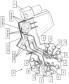
도 1은 본 발명에 따른 약물 전달 디바이스의 아키텍처, 용기 연통, 및 기능적 컴포넌트를 도시하는 개략도이다.
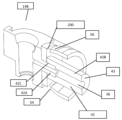
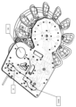
도 2는 상부 하우징이 제거된 본 발명에 따른 약물 전달 디바이스의 등각 블록 모델이다.
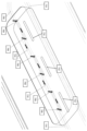
도 3은 약물 전달 디바이스 내의 컴포넌트의 위치설정을 보여주는, 도 2의 실시예의 등각 은선도이다.
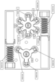
도 4는 본체를 보여주기 위해 배리어가 제거된 도 3의 실시예의 등각도이다.
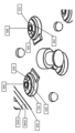
도 5는 약물 카트리지를 보여주기 위해 희석제 팩이 제거된 도 4의 실시예의 등각도이다.
도 6은 도 5의 약물 카트리지 및 본체의 확대도이다.
도 6a는 각각 3개의 약물 용기로 구성된 3개의 세트가 본체에 연결되는 조립 구성의 개략도이다.
도 6b는 5개의 약물 용기로 구성된 하나의 그룹과 2개의 약물 용기로 구성된 2개의 그룹이 본체에 연결되는 조립 구성의 개략도이다.
도 6c는 5개의 약물 용기로 구성된 하나의 그룹, 3개의 약물 용기로 구성된 하나의 그룹, 및 별개의 단일 약물 용기가 본체에 연결되는 조립 구성의 개략도이다.
도 6d는 도 6b의 각각의 그룹에 대한 다수의 약물 용기가 단일의 더 큰 약물 용기로 대체되는 조립 구성의 개략도이다.
도 7은 본 발명에 따른, 조립된 상태의 저장소 섹션 및 플러그 어댑터를 포함하는 약물 카트리지의 단면도이다.
도 8은 본 발명에 따른 약물 카트리지의 저장소 섹션의 단면도이다.
도 8a는 부분적으로 접힌 저장소가 있는 도 8의 저장소 컴포넌트를 도시한다.
도 9는 본 발명에 따른 약물 카트리지의 플러그 어댑터 컴포넌트의 단면도이다.
도 10은 본 발명에 따른 반경방향으로 밀봉된 마개를 예시하는 약물 카트리지의 단면도이다.
도 11은 강성 셸의 하부 부분이 없는, 도 10의 약물 카트리지의 단면도이다.
도 12는 본 발명에 따른 통기된 상태의 약물 카트리지를 도시한다.
도 13은 본 발명에 따른 반경방향 밀봉에 사용 가능한 플러그 어댑터의 상세도이다.
도 14는 도 13의 플러그 어댑터의 단면도이다.
도 15는 본 발명에 따른 반경방향 밀봉에 사용 가능한 저장소 섹션의 등각도이다.
도 16은 반경방향으로 밀봉된 마개에 대한 유지 피처를 예시하기 위한 도 15의 저장소 섹션의 대안적인 도면이다.
도 17a는 본 발명에 따라 충전을 위해 배향된 저장소 섹션을 도시한다.
도 17b는 플러그 어댑터가 통기 위치에 있는 도 17a의 저장소 섹션을 도시한다.
도 17c는 도 17a의 저장소 섹션에 완전히 안착된 플러그 어댑터를 도시한다.
도 18은 본 발명에 따른 내부 보유 피처를 갖는 면 밀봉부를 예시하는 약물 카트리지의 단면도이다.
도 19는 본 발명에 따른 내부 유동 채널을 예시하는 약물 카트리지의 단면도이다.
도 20a는 본 발명에 따라 충전을 위해 배향된, 개방된 저장소 섹션을 도시한다.
도 20b는 플러그 어댑터가 통기 위치에 있는 도 20a의 저장소 섹션을 도시한다.
도 20c는 도 20a의 저장소 섹션에 완전히 안착된 플러그 어댑터를 도시한다.
도 21은 본 발명에 따라 저장소의 완전한 팽창을 허용하는 강성 셸을 갖는 약물 카트리지를 도시한다.
도 22는 본 발명에 따라 저장소의 팽창을 제한하는 강성 셸을 갖는 약물 카트리지를 도시한다.
도 23은 면 밀봉부 및 내향으로 지향된 디텐트를 이용하는 본 발명에 사용 가능한 플러그 어댑터를 도시한다.
도 24는 밀봉부가 제자리에 있는 도 23의 플러그 어댑터의 단면도를 도시한다.
도 25는 밀봉부가 제자리에 없는 도 23의 플러그 어댑터의 단면도를 도시한다.
도 26은 도 23의 면 밀봉부 플러그 어댑터에 조립될 수 있는 저장소를 도시한다.
도 27은 도 26의 면 밀봉부 저장소와 도 23의 플러그 어댑터를 이용하는 약물 카트리지의 단면도이다.
도 28은 도 27의 약물 카트리지의 등각도이다.
도 29는 면 밀봉부 저장소 및 플러그 어댑터를 이용하는 약물 카트리지의 단면도이며, 플러그 어댑터는 목부(neck)를 따라 통기 통로를 갖고, 저장소는 테이퍼진 목부를 갖고 있다.
도 30은 밀봉된 위치에 있는 도 29의 약물 카트리지의 단면도이다.
도 31a는 도 29의 약물 카트리지의 밀봉 요소의 등각도이다.
도 31b는 도 31a의 밀봉 요소의 단면도이다.
도 32a는 플러그 어댑터와 저장소 섹션 사이의 래칭 배열을 이용하는 약물 카트리지의 등각도이다.
도 32b는 도 32a의 약물 카트리지의 분해 등각도이다.
도 32c는 통기 위치에 있는 도 32a의 플러그 어댑터를 도시한다.
도 32d는 밀봉된 위치에 있는 도 32a의 플러그 어댑터를 도시한다.
도 32e는 플러그 어댑터가 밀봉된 위치에 있는 도 32d의 약물 카트리지의 단면도이다.
도 33a는 통기 위치에 있는 도 31a의 밀봉 요소를 도시한다. 절단면은 돌출된 비드가 보이도록 위치된다.
도 33b는 동결 건조를 위해 통기 위치에 있는 도 31a의 밀봉 요소를 도시한다.
도 33c는 밀봉된 위치에 있는 도 31a의 밀봉 요소를 도시한다.
도 34a는 본 발명에 따라 밀봉된 위치에 있는 플러그 어댑터의 단면도이다.
도 34b는 본 발명에 따라 플러그 어댑터에 사용 가능한 밸브의 사시도이다.
도 34c는 밀봉된 위치에서 도 34a의 밸브를 사용하는 플러그 어댑터의 단면도이다.
도 35a는 개방된 위치에 있는 도 34의 플러그 어댑터의 단면도이다.
도 35b는 개방된 위치에서, 도 34a의 밸브를 사용하는 플러그 어댑터의 단면도이다.
도 36a는 본 발명에 따라 플러그를 이동시켜 약물 카트리지에 접근하는 방법을 도시한다.
도 36b는 본 발명에 따라 출구로부터 멀리 밀봉부를 활주시켜 약물 카트리지에 접근하는 방법을 도시한다.
도 36c는 본 발명에 따라 뚜껑을 이동시켜 약물 카트리지에 접근하는 방법을 도시한다.
도 36d는 본 발명에 따라 래치를 개방하여 약물 카트리지에 접근하는 방법을 도시한다.
도 36e는 본 발명에 따라 내부 스프링을 사용하여 플러그를 이동시켜 약물 카트리지에 접근하는 방법을 도시한다.
도 37a는 본 발명에 따라 필름을 박리하여 약물 카트리지에 접근하는 방법을 도시한다.
도 37b는 본 발명에 따라 기전력으로 필름을 파열시켜 약물 카트리지에 접근하는 방법을 도시한다.
도 37c는 본 발명에 따라 스프링력을 사용하여 필름을 파열시켜 약물 카트리지에 접근하는 방법을 도시한다.
도 37d는 본 발명에 따라 회전 운동을 사용해서 필름을 절단하여 약물 카트리지에 접근하는 방법을 도시한다.
도 38a는 본 발명에 따라 절취선을 따라 절단하여 약물 카트리지에 접근하는 방법을 도시한다.
도 38b는 본 발명에 따라 절취선을 따라 전단하여 약물 카트리지에 접근하는 방법을 도시한다.
도 39a는 본 발명에 따라 유체 경로를 덮고 있는 필름의 2개의 에지를 맞물리게 하여 약물 카트리지에 접근하는 방법을 도시한다. 이 도면에서는, 필름이 평탄한 표면에 장착되어 있다.
도 39b는 본 발명에 따라 유체 경로를 덮고 있는 필름의 2개의 에지를 맞물리게 하여 약물 카트리지에 접근하는 방법을 도시한다. 이 도면에서는, 필름이 원통형 표면에 장착되어 있다.
도 39c는 본 발명에 따라 내부 컴포넌트의 상대 회전을 통해 필름을 박리하여 약물 카트리지에 접근하는 방법을 도시한다.
도 39d는 본 발명에 따라 볼 밸브형 요소를 통해 필름을 박리하여 약물 카트리지에 접근하는 방법을 도시한다.
도 40a-1은 본 발명에 따라 2개의 밀봉부를 이동시켜 약물 카트리지에 접근하기 위한 시스템의 초기 밀봉 상태를 도시한다.
도 40a-2는 도 40a-1의 시스템의 최종 개방 상태를 도시한다.
도 40b는 본 발명에 따라 소독제 저장소와 활주 가능한 피스톤을 사용하여 유체 경로의 오염을 제거하는 방법을 도시한다.
도 40c는 본 발명에 따라 제거 가능한 측방향 밀봉부와 클램핑 메커니즘을 사용하여 약물 카트리지에 접근하는 방법을 도시한다.
도 41a는 본 발명에 따라 캐뉼러에 의해 관통되는 소독제 저장소를 사용하여 유체 경로의 오염을 제거하는 방법을 도시한다.
도 41b는 본 발명에 따라 단일 팁 외장 바늘 및 격막을 사용하여 약물 카트리지에 접근하는 방법을 도시한다.
도 41c는 사용 중인 도 41b의 시스템을 도시한다.
도 41d는 본 발명에 따라 이중 팁 외장 바늘 및 격막을 사용하여 약물 카트리지에 접근하는 방법을 도시한다.
도 41e는 본 발명에 따라 약물 카트리지 출구 내에서 사전 로딩된 상태의 스프링 로딩 바늘을 사용하여 약물 카트리지에 접근하는 방법을 도시한다.
도 41f는 본 발명에 따라 약물 카트리지 출구 내에서 연장된 상태의 스프링 로딩 바늘을 사용하여 약물 카트리지에 접근하는 방법을 도시한다.
도 42는 본 발명에 따라 사용 가능한 유체 경로를 예시하는 약물 전달 디바이스의 단면도이다.
도 43은 도 42의 단면의 상세도이다.
도 44는 본 발명에 사용 가능한 본체의 등각도이다.
도 45는 배리어가 있는 도 44의 본체를 도시한다.
도 46은 멸균이 필요한 약물 전달 디바이스의 잠재적인 비멸균 구역을 보여주는 단면도이다.
도 47은 멸균이 필요한 약물 전달 디바이스의 잠재적인 비멸균 구역을 보여주는 등각도이다.
도 48은 자외선 방사선, 펄스광 또는 전자 빔을 통해 멸균되어야 하는 약물 전달 디바이스의 구역과 그렇지 않은 구역을 보여주는 단면도이다.
도 49 내지 도 49c는 자외선 방사선 또는 펄스광의 침투를 차단하기 위해 약물 전달 디바이스에서 첨가제가 이용될 수 있는 위치를 도시한다.
도 50은 도 49에 도시된 위치 이외의 추가적인 위치를 도시하며, 여기서는 자외선 방사선 또는 펄스광의 침투를 차단하기 위해 첨가제를 이용할 수 있다.
도 51은 도 50에 도시된 차단 컴포넌트를 예시하는 약물 전달 디바이스의 전체 단면도이다.
도 52는 자외선 방사선, 펄스광 또는 전자 빔 방사선을 차단하기 위한 차폐물을 보여주는 약물 전달 디바이스의 단면도이다.
도 52a는 자외선 방사선, 펄스광 또는 전자 빔 방사선을 차단하기 위한 대안적인 차폐물을 보여주는 약물 전달 디바이스의 단면도이다.
도 52b는 도 52a에 도시된 차폐물의 평면도이다.
도 53은 본 발명에 따른 유체 경로 및 밸브 구성을 보여주는 약물 전달 디바이스의 단면도이다.
도 54는 디바이스의 본체에 초점을 맞춘 도 53의 단면의 상세도이다.
도 55는 본 발명에 따른 밸브가 폐쇄 상태에 있는 약물 전달 디바이스의 본체에 장착된 약물 카트리지를 도시한다.
도 56은 밸브가 개방 상태에 있고 유로를 정의하는 도 55의 약물 카트리지를 도시한다.
도 57은 도 56의 단면의 상세도이다.
도 58은 본 발명에 따른 건조 제품에 사용 가능한 저장소 지지부가 있는 약물 카트리지를 도시한다.
도 59는 사용 중인 도 58의 저장소 지지부를 도시한다.
도 60은 본 발명에 따른 건조 제품에 사용 가능한 대안적인 저장소 지지부가 있는 약물 카트리지를 도시한다.
도 61은 사용 중인 도 60의 저장소 지지부를 도시한다.
도 62는 본 발명에 따른 저장소 지지부 고정 장치를 갖는 약물 카트리지를 도시한다.
도 63은 사용 중인 도 62의 저장소 지지부 고정 장치를 도시한다.
도 64a는 본 발명에 사용 가능한 지그를 도시한다.
도 64b는 본 발명에 사용 가능한 개방형 지그를 도시한다.
도 64c는 본 발명에 사용 가능한 트레이를 도시한다.
도 64d는 약물 카트리지가 로딩된 도 64c의 트레이를 도시한다.
도 64e는 터브(tub)에 배치된 도 64d의 로딩된 트레이를 도시한다.
도 65는 본 발명에 따른 배럴형 약물 카트리지를 갖는 약물 전달 디바이스를 도시한다.
도 66은 도 65의 약물 전달 디바이스의 단면도이다.
도 67a는 본 발명에 따른 밀봉된 상태의 배럴형 약물 카트리지를 도시한다.
도 67b는 작동된 상태의 도 67a의 약물 카트리지를 도시한다.
도 68은 우회 채널을 갖는 배럴형 약물 카트리지의 다양한 구성을 예시한다.
도 69는 도 65의 약물 전달 디바이스 일부의 멸균을 도시한다.
도 70은 본 발명에 따른 대안적인 배럴형 약물 카트리지를 갖는 약물 전달 디바이스를 도시한다.
도 71은 도 70의 약물 전달 디바이스의 등각도이다.
도 72는 도 70의 약물 전달 디바이스의 단면도이다.
도 73a는 약물 전달 디바이스의 본체에서 자외선 방사선 노출을 위한 위치를 개략적으로 도시한다.
도 73b는 3초 동안 자외선 방사선에 노출된 후 달성된 UV 임계 선량을 도시한다.
도 73c는 30초 동안 자외선 방사선에 노출된 후 달성된 UV 임계 선량을 도시한다.
도 74는 본 발명에 따른 추가의 대안적인 배럴형 약물 카트리지를 갖는 약물 전달 디바이스를 도시한다.
도 75는 도 74의 약물 전달 디바이스의 플런저 작동을 도시한다.
도 76은 도 75에 도시된 동작에 이은 반대 방향의 플런저 작동을 도시한다.
도 77은 도 76에 도시된 동작에 이은 다른 배럴로의 플런저 회전을 도시한다.
도 78은 도 77에 도시된 동작에 이은 플런저 작동을 도시한다.
도 79a는 본 발명에 따라 클립을 통해 환자의 의복에 착용되는 약물 전달 디바이스를 도시한다.
도 79b는 도 79a의 약물 전달 디바이스의 측면도이다.
도 80a는 본 발명에 따라 환자의 복부에 접착제를 통해 착용되는 약물 전달 디바이스를 도시한다.
도 80b는 도 80a의 약물 전달 디바이스의 측면도이다.
도 81a는 본 발명에 따라 환자의 허리에 걸쳐 스트랩 또는 벨트를 통해 착용되는 약물 전달 디바이스를 도시한다.
도 81b는 도 81a의 약물 전달 디바이스의 측면도이다.
도 82a는 본 발명에 사용 가능한 대안적인 플러그 어댑터의 평면도이다.
도 82b는 도 82a의 플러그 어댑터의 단면도이다.
도 83a는 도 82a의 플러그 어댑터를 포함하는 약물 카트리지의 평면도이다.
도 83b는 페룰(ferrule)과 조립되기 전의, 도 83a의 약물 카트리지의 단면도이다.
도 84a는 페룰이 장착된, 도 83a의 약물 카트리지의 평면도이다.
도 84b는 도 84a의 약물 카트리지의 단면도이다.
도 85는 본 발명에 따른 페룰이 장착된 약물 카트리지의 등각도이다.
도 86은 도 85의 약물 카트리지의 단면도이다.
도 87a는 본 발명에 사용 가능한 대안적인 플러그 어댑터의 측면도이다.
도 87b는 도 87a의 플러그 어댑터의 단면도이다.
도 88a는 도 87a의 플러그 어댑터를 포함하는 약물 카트리지의 평면도이다.
도 88b는 페룰과 조립되기 전의, 도 88a의 약물 카트리지의 단면도이다.
도 89a는 페룰이 장착된, 도 88a의 약물 카트리지의 평면도이다.
도 89b는 도 89a의 약물 카트리지의 단면도이다.
도 90 내지 도 94b는 본 발명에 사용 가능한 다양한 유체공학적 배열을 도시하는 개략도이다.
도 95는 본 발명에 사용 가능한 변위 가능한 작동기 플레이트의 단면도이다.
도 96a는 기어 플레이트 위에 놓인 작동기 플레이트의 단면도이다.
도 96b는 작동기 플레이트의 상승을 초래하는 기어 플레이트 회전을 보여주는 도 96a와 유사한 단면도이다.
도 96c는 도 96a의 기어 플레이트의 평면도이다.
도 96d는 도 96a의 측면도이다.
도 96e는 도 96b의 측면도이다.
도 97a는 작동기 플레이트가 하강된 위치에 있는 측면도이다.
도 97b는 밸브의 변위를 초래하는 도 97a의 위치로부터 상승된 작동기 플레이트를 보여주는 측면도이다.
도 98은 밸브를 개방 상태로 강제하도록 배열된 편향 수단의 단면도이다.
도 99는 본 발명에 사용 가능한 진동 플레이트의 평면도이다.
도 100은 본 발명에 사용 가능한 회전 또는 발진 턴테이블의 평면도이다.
도 101은 본 발명에 사용 가능한 내장 가속도계의 평면도이다.
도 102는 본 발명에 사용 가능한 내장 압전 작동기의 평면도이다.
도 103은 본 발명에 사용 가능한 자기 교반기를 도시한다.
도 104는 본 발명에 사용 가능한, 약물 전달 디바이스의 약물 카트리지 아래에 위치될 수 있는 낮은 프로파일의 접이식 저장소를 도시한다.
도 105a 내지 도 112는 본 발명에 사용 가능한 재구성 동안의 혼합물의 순환을 위한 다양한 배열을 도시한 도면이다.
도 113은 본 발명에 사용 가능한 통기구의 상부 사시도이다.
도 114에는 본 발명에 사용 가능한 통기구의 평면도 및 측면도가 포함되어 있다.
도 115는 본 발명에 사용 가능한 직선형 채널이 내부에 형성된 통기구의 베이스 플레이트의 평면도이다.
도 116은 본 발명에 사용 가능한 구불구불한 경로를 정의하는 채널이 내부에 형성된 통기구의 베이스 플레이트의 평면도이다.
도 116a 내지 도 116c는 수직 방향으로 변화되는 구불구불한 경로를 갖는 통기구의 대안적인 실시예를 도시한다.
도 117은 본 발명에 사용 가능한 확대된 부분을 갖는 채널이 내부에 형성된 통기구의 베이스 플레이트의 평면도이다.
도 117a 및 도 117b는 발산 섹션과 수렴 섹션을 각각 갖는 확대된 부분이 있는 통기구를 도시한다.
도 118a는 본 발명에 사용 가능한 밸브 모듈의 평면도이다.
도 118b는 본 발명에 사용 가능한 작동기 기어와 웜 기어의 대안적인 배열의 평면도이다.
도 119는 작동기 기어가 제거된 도 118a의 밸브 모듈의 상부 사시도이다.
도 120은 도 119의 밸브 모듈의 평면도이다.
도 121a는 판 스프링이 제거된 도 119의 밸브 모듈 부분의 평면도이다.
도 121b는 판 스프링과 작동기 기어가 제거된 도 118의 밸브 모듈 부분의 평면도이다.
도 122a는 밸브의 가요성 본체가 제거된 도 121b의 부분 밸브 모듈의 상부 사시도이다.
도 122b는 밸브의 가요성 본체가 제거된 도 121a의 부분 밸브 모듈 부분의 확대도이다.
도 123a는 밸브의 가요성 본체가 제거된 도 121a의 부분 밸브 모듈의 평면도이다.
도 123b는 유동 채널 위에 밸브가 겹쳐져 있는 도 122a의 평면도이다.
도 124는 상부 층이 제거된 도 123a의 부분 밸브 모듈의 상부 사시도이다.
도 125는 도 124의 부분 밸브 모듈에 사용 가능한 제2 중간 층의 상부 사시도이다.
도 126a 내지 도 126d는 도 124의 부분 밸브 모듈의 측면도이다.
도 127은 도 126a의 확대된 부분이다.
도 128은 도 125의 제2 중간 층의 상부 사시도이다.
도 129는 도 125의 제2 중간 층의 평면도이다.
도 130은 도 125의 제2 중간 층의 저면도이다.
도 131은 도 118a의 밸브 모듈의 단면도이다.
도 132는 본 발명에 사용 가능한 작동기 기어 판 스프링의 배열의 상부 사시도이다.
도 133은 작동기 기어가 투명하게 도시된 도 132의 배열의 상부 사시도이다.
도 134는 판 스프링이 제거된 도 132의 배열의 상부 사시도이다.
도 135는 편향되지 않은 상태의 밸브를 보여주는 도 131의 확대된 부분이다.
도 136은 편향된 상태의 도 135의 밸브를 도시한다.
도 137은 작동기 기어가 제거된 도 131의 상부 사시도이다.
도 138은 도 137의 측면도이다.
도 139a는 본 발명에 사용 가능한 밸브 및 작동기 기어 세트의 배열을 개략적으로 도시한다.
도 139b는 도 139a의 밸브의 개략도와 밸브가 유체공학적으로 결합될 수 있는 약물 전달 디바이스의 피처를 도시한다.
도 139c는 도 139a 및 도 140a에 도시된 밸브의 배치를 표시한 도 124의 복제본이다.
도 139d 및 도 139e는 각각 밸브 사이의 유체 연결과 밸브가 유체공학적으로 결합될 수 있는 약물 전달 디바이스의 피처를 표시하여 보여주는 도 129 및 도 130의 복제본이다.
도 140a는 본 발명에 사용 가능한 밸브 세트와 작동기 기어의 대안적인 배열을 개략적으로 도시한다.
도 140b는 도 140a의 밸브 및 밸브가 유체공학적으로 결합될 수 있는 약물 전달 디바이스의 피처의 개략도를 도시한다.
도 141은 본 발명에 따른 약물 전달 디바이스의 상부 사시도를 도시한다.
도 142는 저장소가 제거된 도 141의 약물 전달 디바이스의 상부 사시도이다.
도 143은 배리어가 제거된 저장소를 갖는 도 141의 약물 전달 디바이스의 상부 사시도이다.
도 144는 내부 통로를 보여주기 위해 도 143을 투명하게 도시한다.
도 145는 본 발명에 사용 가능한 대안적인 밸브 모듈의 상부 사시도이다.
도 146은 특정 부분이 투명하게 도시되어 있는 도 145의 확대도이다.
도 147은 도 145의 밸브 모듈용 작동기 기어의 배치를 보여주는 측면도이다.
도 148a 및 도 148b는 편향되지 않은 상태(도 148b)에서 편향된 상태(도 148a)로 (내부를 향하는) 하향 방향으로 편향되도록 구성된 밸브를 개략적으로 도시한다.
도 149는 본 발명에 사용 가능한 대안적인 밸브 모듈의 상부 사시도이다.
도 150은 특정 부분이 투명하게 도시된 도 149의 복제본이다.
도 151은 도 149의 밸브 모듈의 저면 사시도이다.
도 152는 내부 통로를 투명하게 보여주는 도 140의 밸브 모듈의 평면도이다.
도 153은 도 152의 확대된 부분이다.
도 154는 도 153에 도시된 확대된 부분의 상부 사시도이다.
도 155는 하나 이상의 유체 덕트를 정의하는 튜브를 보여주는 도 149의 밸브 모듈 부분의 측면도이다.
도 156 내지 도 167은 본 발명에 따른 부압 또는 정압 하의 약물 전달 디바이스의 예시적인 유체 유동을 도시한다.
도 168 내지 도 172는 본 발명에 따른 부압 및 정압을 이용하는 약물 전달 디바이스의 예시적인 완전한 유동을 도시한다.
도 173 내지 도 186은 본 발명에 따른 약물 전달 디바이스에 사용 가능한 약물 카트리지의 대안적인 실시예를 도시한다.
도 187 내지 도 198은 본 발명에 따른 약물 카트리지에 사용 가능한 밀봉부를 도시한다.
도 199 내지 도 207은 본 발명에 따른, 도 187 내지 도 198에 도시된 밀봉부를 개방하기 위한 작동기를 도시한다.1 is a schematic diagram showing the architecture, vessel communication, and functional components of a drug delivery device according to the present invention.
Figure 2 is an isometric block model of the drug delivery device according to the invention with the upper housing removed.
Figure 3 is an isometric schematic diagram of the embodiment of Figure 2, showing positioning of components within the drug delivery device.
Figure 4 is an isometric view of the embodiment of Figure 3 with the barrier removed to show the main body.
Figure 5 is an isometric view of the embodiment of Figure 4 with the diluent pack removed to show the drug cartridge.
Figure 6 is an enlarged view of the drug cartridge and body of Figure 5.
Figure 6A is a schematic diagram of an assembly configuration in which three sets of three drug containers each are connected to the main body.
Figure 6b is a schematic diagram of an assembly configuration in which one group of five drug containers and two groups of two drug containers are connected to the main body.
Figure 6C is a schematic diagram of an assembly configuration in which one group of five drug containers, one group of three drug containers, and a separate single drug container are connected to the body.
Figure 6D is a schematic diagram of an assembly configuration in which multiple drug containers for each group of Figure 6B are replaced with a single, larger drug container.
Figure 7 is a cross-sectional view of a drug cartridge comprising a reservoir section and a plug adapter in an assembled state, according to the present invention.
Figure 8 is a cross-sectional view of the reservoir section of a drug cartridge according to the present invention.
FIG. 8A shows the storage component of FIG. 8 with the storage partially collapsed.
Figure 9 is a cross-sectional view of the plug adapter component of a drug cartridge according to the present invention.
Figure 10 is a cross-sectional view of a drug cartridge illustrating a radially sealed closure according to the present invention.
Figure 11 is a cross-sectional view of the drug cartridge of Figure 10, without the lower portion of the rigid shell.
Figure 12 shows a drug cartridge in an aerated state according to the present invention.
Figure 13 is a detailed view of a plug adapter usable for radial sealing according to the present invention.
Figure 14 is a cross-sectional view of the plug adapter of Figure 13.
Figure 15 is an isometric view of a reservoir section usable for radial sealing according to the invention.
Figure 16 is an alternative view of the reservoir section of Figure 15 to illustrate retention features for a radially sealed closure.
Figure 17a shows a reservoir section oriented for filling according to the invention.
FIG. 17B shows the reservoir section of FIG. 17A with the plug adapter in the vented position.
Figure 17c shows the plug adapter fully seated in the reservoir section of Figure 17a.
Figure 18 is a cross-sectional view of a drug cartridge illustrating a face seal with internal retention features in accordance with the present invention.
Figure 19 is a cross-sectional view of a drug cartridge illustrating the internal flow channel according to the present invention.
Figure 20a shows an open reservoir section, oriented for filling according to the invention.
FIG. 20B shows the reservoir section of FIG. 20A with the plug adapter in the vented position.
Figure 20C shows the plug adapter fully seated in the reservoir section of Figure 20A.
Figure 21 shows a drug cartridge with a rigid shell allowing full expansion of the reservoir according to the present invention.
Figure 22 shows a drug cartridge with a rigid shell limiting expansion of the reservoir in accordance with the present invention.
Figure 23 shows a plug adapter usable in the present invention utilizing a face seal and an inwardly oriented detent.
Figure 24 shows a cross-sectional view of the plug adapter of Figure 23 with the seal in place.
Figure 25 shows a cross-sectional view of the plug adapter of Figure 23 without the seal in place.
Figure 26 shows a reservoir that can be assembled to the face seal plug adapter of Figure 23;
Figure 27 is a cross-sectional view of a drug cartridge utilizing the face seal reservoir of Figure 26 and the plug adapter of Figure 23.
Figure 28 is an isometric view of the drug cartridge of Figure 27.
Figure 29 is a cross-sectional view of a drug cartridge utilizing a cotton seal reservoir and a plug adapter, the plug adapter having a vent passage along the neck and the reservoir having a tapered neck.
Figure 30 is a cross-sectional view of the drug cartridge of Figure 29 in a sealed position.
Figure 31A is an isometric view of the sealing element of the drug cartridge of Figure 29.
Figure 31b is a cross-sectional view of the sealing element of Figure 31a.
Figure 32A is an isometric view of a drug cartridge utilizing a latching arrangement between a plug adapter and a reservoir section.
Figure 32B is an exploded isometric view of the drug cartridge of Figure 32A.
Figure 32C shows the plug adapter of Figure 32A in the vented position.
Figure 32D shows the plug adapter of Figure 32A in a sealed position.
Figure 32E is a cross-sectional view of the drug cartridge of Figure 32D with the plug adapter in the sealed position.
Figure 33a shows the sealing element of Figure 31a in a vented position. The cut surface is positioned so that the protruding bead is visible.
Figure 33b shows the sealing element of Figure 31a in vented position for freeze drying.
Figure 33c shows the sealing element of Figure 31a in a sealed position.
Figure 34A is a cross-sectional view of the plug adapter in a sealed position in accordance with the present invention.
Figure 34b is a perspective view of a valve usable in a plug adapter according to the present invention.
Figure 34C is a cross-sectional view of a plug adapter using the valve of Figure 34A in a sealed position.
Figure 35A is a cross-sectional view of the plug adapter of Figure 34 in an open position.
Figure 35b is a cross-sectional view of a plug adapter using the valve of Figure 34a, in an open position.
Figure 36A shows how to move a plug to access a drug cartridge in accordance with the present invention.
Figure 36B illustrates a method of accessing a drug cartridge by sliding the seal away from the outlet in accordance with the present invention.
Figure 36C illustrates how to access a drug cartridge by moving the lid in accordance with the present invention.
36D illustrates how to open a latch to access a drug cartridge in accordance with the present invention.
Figure 36E illustrates a method of accessing a drug cartridge by moving a plug using an internal spring in accordance with the present invention.
Figure 37A shows a method of accessing a drug cartridge by peeling off a film in accordance with the present invention.
Figure 37b illustrates a method of accessing a drug cartridge by rupturing the film with electromotive force according to the present invention.
Figure 37C illustrates a method of accessing a drug cartridge by rupturing the film using spring force in accordance with the present invention.
Figure 37D illustrates how to access a drug cartridge by cutting the film using a rotational motion in accordance with the present invention.
Figure 38A shows a method of accessing a drug cartridge by cutting along a perforation line in accordance with the present invention.
Figure 38B shows a method of accessing a drug cartridge by shearing along a perforation line in accordance with the present invention.
Figure 39A shows a method of accessing a drug cartridge by engaging two edges of the film covering the fluid path according to the present invention. In this figure, the film is mounted on a flat surface.
Figure 39B shows a method of accessing a drug cartridge by engaging two edges of the film covering the fluid path according to the present invention. In this figure, the film is mounted on a cylindrical surface.
Figure 39C shows a method of accessing a drug cartridge by peeling the film through relative rotation of the internal components in accordance with the present invention.
Figure 39d shows a method of accessing a drug cartridge by peeling the film through a ball valve-like element according to the present invention.
Figure 40A-1 shows the initial sealing state of the system for accessing a drug cartridge by moving two seals according to the present invention.
Figure 40A-2 shows the final open state of the system of Figure 40A-1.
Figure 40B illustrates a method of decontaminating a fluid path using a disinfectant reservoir and a slideable piston in accordance with the present invention.
Figure 40C illustrates a method of accessing a drug cartridge using a removable lateral seal and clamping mechanism in accordance with the present invention.
Figure 41A illustrates a method of decontaminating a fluid path using a disinfectant reservoir penetrated by a cannula in accordance with the present invention.
Figure 41B illustrates a method of accessing a drug cartridge using a single tip external needle and septum in accordance with the present invention.
Figure 41C shows the system of Figure 41B in use.
Figure 41D illustrates a method of accessing a drug cartridge using a double tip external needle and septum in accordance with the present invention.
Figure 41E illustrates a method of accessing a drug cartridge using a spring-loaded needle in a pre-loaded state within the drug cartridge outlet according to the present invention.
Figure 41F illustrates a method of accessing a drug cartridge using a spring-loaded needle extended within the drug cartridge outlet in accordance with the present invention.
Figure 42 is a cross-sectional view of a drug delivery device illustrating the fluidic pathways usable in accordance with the present invention.
Figure 43 is a detailed view of the cross section of Figure 42.
Figure 44 is an isometric view of a body usable in the present invention.
Figure 45 shows the body of Figure 44 with a barrier.
Figure 46 is a cross-sectional view showing potentially non-sterile areas of a drug delivery device requiring sterilization.
Figure 47 is an isometric view showing potential non-sterile areas of a drug delivery device requiring sterilization.
Figure 48 is a cross-sectional view showing areas of a drug delivery device that should be sterilized via ultraviolet radiation, pulsed light, or electron beam and areas that should not.
49-49C illustrate locations where additives can be used in a drug delivery device to block penetration of ultraviolet radiation or pulsed light.
Figure 50 shows additional locations other than those shown in Figure 49, where additives may be used to block penetration of ultraviolet radiation or pulsed light.
Figure 51 is a cross-sectional view of a drug delivery device illustrating the blocking component shown in Figure 50.
Figure 52 is a cross-sectional view of a drug delivery device showing a shield for blocking ultraviolet radiation, pulsed light, or electron beam radiation.
Figure 52A is a cross-sectional view of a drug delivery device showing alternative shielding for blocking ultraviolet radiation, pulsed light, or electron beam radiation.
Figure 52b is a top view of the shield shown in Figure 52a.
Figure 53 is a cross-sectional view of a drug delivery device showing the fluid path and valve configuration according to the present invention.
Figure 54 is a detailed view of the cross-section of Figure 53 focusing on the body of the device.
Figure 55 shows a drug cartridge mounted on the body of a drug delivery device with the valve according to the invention in a closed state.
Figure 56 shows the drug cartridge of Figure 55 with the valve in the open position and defining the flow path.
Figure 57 is a detailed view of the cross section of Figure 56.
Figure 58 shows a drug cartridge with reservoir support usable for dry products according to the invention.
Figure 59 shows the reservoir support of Figure 58 in use.
Figure 60 shows a drug cartridge with an alternative reservoir support usable for dry products according to the invention.
Figure 61 shows the reservoir support of Figure 60 in use.
Figure 62 shows a drug cartridge with a reservoir support fastening device according to the invention.
Figure 63 shows the reservoir support securing device of Figure 62 in use.
Figure 64A shows a jig usable in the present invention.
Figure 64b shows an open jig usable in the present invention.
Figure 64C shows a tray usable in the present invention.
Figure 64D shows the tray of Figure 64C loaded with drug cartridges.
Figure 64E shows the loaded tray of Figure 64D placed in a tub.
Figure 65 shows a drug delivery device with a barrel-shaped drug cartridge according to the present invention.
Figure 66 is a cross-sectional view of the drug delivery device of Figure 65.
Figure 67a shows a barrel-shaped drug cartridge in a sealed state according to the present invention.
Figure 67B shows the drug cartridge of Figure 67A in actuated condition.
Figure 68 illustrates various configurations of a barrel-shaped drug cartridge with a bypass channel.
Figure 69 depicts sterilization of a portion of the drug delivery device of Figure 65.
Figure 70 shows a drug delivery device with an alternative barrel-shaped drug cartridge according to the present invention.
Figure 71 is an isometric view of the drug delivery device of Figure 70.
Figure 72 is a cross-sectional view of the drug delivery device of Figure 70.
Figure 73A schematically depicts locations for ultraviolet radiation exposure in the body of the drug delivery device.
Figure 73B shows the UV threshold dose achieved after exposure to ultraviolet radiation for 3 seconds.
Figure 73C shows the UV threshold dose achieved after exposure to ultraviolet radiation for 30 seconds.
Figure 74 shows a drug delivery device with a further alternative barrel-shaped drug cartridge according to the present invention.
Figure 75 shows plunger actuation of the drug delivery device of Figure 74.
Figure 76 shows plunger operation in the opposite direction following the operation shown in Figure 75.
Figure 77 shows plunger rotation into another barrel following the operation shown in Figure 76.
Figure 78 shows plunger operation following the operation shown in Figure 77.
Figure 79A shows a drug delivery device worn on a patient's clothing via a clip according to the present invention.
Figure 79B is a side view of the drug delivery device of Figure 79A.
Figure 80A shows a drug delivery device worn via adhesive on a patient's abdomen according to the present invention.
Figure 80B is a side view of the drug delivery device of Figure 80A.
Figure 81A shows a drug delivery device worn via a strap or belt across a patient's waist in accordance with the present invention.
Figure 81B is a side view of the drug delivery device of Figure 81A.
Figure 82A is a top view of an alternative plug adapter usable in the present invention.
Figure 82b is a cross-sectional view of the plug adapter of Figure 82a.
Figure 83A is a top view of a drug cartridge including the plug adapter of Figure 82A.
Figure 83B is a cross-sectional view of the drug cartridge of Figure 83A before assembly with a ferrule.
Figure 84A is a top view of the drug cartridge of Figure 83A, equipped with a ferrule.
Figure 84B is a cross-sectional view of the drug cartridge of Figure 84A.
Figure 85 is an isometric view of a drug cartridge equipped with a ferrule according to the present invention.
Figure 86 is a cross-sectional view of the drug cartridge of Figure 85.
Figure 87A is a side view of an alternative plug adapter usable in the present invention.
Figure 87b is a cross-sectional view of the plug adapter of Figure 87a.
Figure 88A is a top view of a drug cartridge including the plug adapter of Figure 87A.
Figure 88B is a cross-sectional view of the drug cartridge of Figure 88A before assembly with a ferrule.
Figure 89A is a top view of the drug cartridge of Figure 88A, equipped with a ferrule.
Figure 89B is a cross-sectional view of the drug cartridge of Figure 89A.
Figures 90-94B are schematic diagrams illustrating various fluidic arrangements usable in the present invention.
Figure 95 is a cross-sectional view of a displaceable actuator plate usable in the present invention.
Figure 96A is a cross-sectional view of the actuator plate overlying the gear plate.
FIG. 96B is a cross-sectional view similar to FIG. 96A showing gear plate rotation resulting in elevation of the actuator plate.
Figure 96c is a top view of the gear plate of Figure 96a.
Figure 96d is a side view of Figure 96a.
Figure 96E is a side view of Figure 96B.
Figure 97A is a side view with the actuator plate in the lowered position.
Figure 97b is a side view showing the actuator plate raised from the position of Figure 97a resulting in displacement of the valve.
Figure 98 is a cross-sectional view of biasing means arranged to force the valve into the open state;
Figure 99 is a top view of a vibration plate usable in the present invention.
Figure 100 is a plan view of a rotating or oscillating turntable usable in the present invention.
Figure 101 is a top view of a built-in accelerometer usable in the present invention.
Figure 102 is a top view of a built-in piezoelectric actuator usable in the present invention.
Figure 103 shows a magnetic stirrer usable in the present invention.
Figure 104 shows a low profile, collapsible reservoir that can be placed beneath a drug cartridge of a drug delivery device, usable in the present invention.
105A-112 illustrate various arrangements for circulation of the mixture during reconstitution that can be used in the present invention.
Figure 113 is a top perspective view of a vent usable in the present invention.
Figure 114 includes a top and side view of a vent usable in the present invention.
Figure 115 is a plan view of a base plate of a vent with a straight channel formed therein that can be used in the present invention.
Figure 116 is a plan view of a base plate of a vent with channels formed therein defining a tortuous path usable in the present invention.
Figures 116a-116c show alternative embodiments of vents with a tortuous path that varies in the vertical direction.
Figure 117 is a top view of a base plate of a vent with a channel formed therein having an enlarged portion usable in the present invention.
Figures 117a and 117b show vents with enlarged portions having diverging and converging sections respectively.
Figure 118a is a top view of a valve module usable in the present invention.
Figure 118B is a top view of an alternative arrangement of actuator gears and worm gears usable in the present invention.
Figure 119 is a top perspective view of the valve module of Figure 118a with the actuator gear removed.
Figure 120 is a top view of the valve module of Figure 119.
FIG. 121A is a top view of a portion of the valve module of FIG. 119 with the leaf springs removed.
FIG. 121B is a top view of a portion of the valve module of FIG. 118 with the leaf spring and actuator gear removed.
Figure 122A is a top perspective view of the partial valve module of Figure 121B with the flexible body of the valve removed.
FIG. 122B is an enlarged view of the partial valve module of FIG. 121A with the flexible body of the valve removed.
Figure 123A is a top view of the partial valve module of Figure 121A with the flexible body of the valve removed.
FIG. 123B is a top view of FIG. 122A with the valve overlaid on the flow channel.
Figure 124 is a top perspective view of the partial valve module of Figure 123A with the top layer removed.
Figure 125 is a top perspective view of a second intermediate layer usable in the partial valve module of Figure 124;
Figures 126A-126D are side views of the partial valve module of Figure 124.
Figure 127 is an enlarged portion of Figure 126a.
Figure 128 is a top perspective view of the second middle layer of Figure 125;
Figure 129 is a plan view of the second middle layer of Figure 125.
Figure 130 is a bottom view of the second middle layer of Figure 125.
Figure 131 is a cross-sectional view of the valve module of Figure 118a.
Figure 132 is a top perspective view of an arrangement of actuator gear leaf springs usable in the present invention.
Figure 133 is a top perspective view of the arrangement of Figure 132 with the actuator gears shown transparently.
Figure 134 is a top perspective view of the arrangement of Figure 132 with the leaf springs removed.
Figure 135 is an enlarged portion of Figure 131 showing the valve in an unbiased state.
Figure 136 shows the valve of Figure 135 in a biased condition.
Figure 137 is a top perspective view of Figure 131 with the actuator gear removed.
Figure 138 is a side view of Figure 137.
Figure 139a schematically shows the arrangement of valve and actuator gear sets usable in the present invention.
Figure 139B shows a schematic diagram of the valve of Figure 139A and features of a drug delivery device to which the valve may be fluidically coupled.
Figure 139C is a replica of Figure 124 showing the arrangement of the valves shown in Figures 139A and 140A.
Figures 139D and 139E are replicas of Figures 129 and 130, respectively, showing the fluidic connections between valves and features of a drug delivery device to which the valves can be fluidically coupled.
Figure 140A schematically shows an alternative arrangement of valve set and actuator gear usable in the present invention.
Figure 140B shows a schematic diagram of the valve of Figure 140A and features of a drug delivery device to which the valve may be fluidically coupled.
Figure 141 shows a top perspective view of a drug delivery device according to the present invention.
Figure 142 is a top perspective view of the drug delivery device of Figure 141 with the reservoir removed.
Figure 143 is a top perspective view of the drug delivery device of Figure 141 with the reservoir with the barrier removed.
Figure 144 shows Figure 143 transparently to show the internal passageway.
Figure 145 is a top perspective view of an alternative valve module usable in the present invention.
Figure 146 is an enlarged view of Figure 145 in which certain parts are shown transparently.
Figure 147 is a side view showing the arrangement of the actuator gear for the valve module of Figure 145.
Figures 148a and 148b schematically show a valve configured to bias in a downward (inward) direction from an unbiased state (Figure 148b) to a biased state (Figure 148a).
Figure 149 is a top perspective view of an alternative valve module usable in the present invention.
Figure 150 is a replica of Figure 149 with certain portions shown as transparent.
Figure 151 is a bottom perspective view of the valve module of Figure 149.
Figure 152 is a top view of the valve module of Figure 140 showing the internal passageway transparently.
Figure 153 is an enlarged portion of Figure 152.
Figure 154 is a top perspective view of the enlarged portion shown in Figure 153.
Figure 155 is a side view of a portion of the valve module of Figure 149 showing tubes defining one or more fluid ducts.
156-167 show exemplary fluid flows of a drug delivery device under negative or positive pressure according to the present invention.
168-172 show exemplary complete flow of a drug delivery device using negative and positive pressure according to the present invention.
Figures 173-186 show alternative embodiments of drug cartridges usable in drug delivery devices according to the invention.
Figures 187-198 show seals usable for drug cartridges according to the invention.
Figures 199-207 show an actuator for opening the seal shown in Figures 187-198, according to the invention.
일 양태에서, 본 발명은 약물 카트리지를 준비하는 방법, 및 이와 별도로 약물 전달 디바이스를 준비하는 방법에 관한 것이다. 도면을 참조하면, 예시적인 약물 전달 디바이스가 도시되어 있으며 참조 번호 10으로 지정되어 있다. 본 기술 분야의 숙련자가 이해하는 바와 같이, 다양한 약물 전달 디바이스가 본 발명의 방법에 의해 준비될 수 있다. 약물 전달 디바이스의 컴포넌트의 구성 및 조립은 다양할 수 있으며 여전히 본 발명의 범위 내에 속한다.In one aspect, the present invention relates to a method of preparing a drug cartridge, and separately a method of preparing a drug delivery device. Referring to the drawings, an exemplary drug delivery device is shown and designated by
도 1을 참조하면, 약물 전달 디바이스(10)는 하나 이상의 약물 카트리지(14)가 부착되는 본체(12)를 포함할 수 있다. 약물 전달 디바이스(10)는 바늘 지지부(16), 펌프(18) 및 제어부(20)를 갖는 신체에 착용 가능한 패치형 약물 전달 디바이스로 도시되어 있다. 컴퓨터 처리 유닛 또는 로직 제어기를 포함할 수 있는 제어부(20)는 약물 카트리지(14)로부터 바늘 지지부(16)에 장착된 환자에의 주사를 위한 바늘(15)까지의 사이에서 약물의 유동을 제어하기 위해 펌프(18)를 제어하도록 구성될 수 있다. 바늘(15)은 표준 피하 바늘 또는 캐뉼러일 수 있거나; 또는 강성 외장에 에워싸인 연질 캐뉼러일 수 있다. 약물(13)은 하나의 약물 카트리지(14)로부터 다른 약물 카트리지로 유동하게 되어, 예를 들어 하나의 약물 카트리지(14)로부터 다른 약물 카트리지(14)로 희석제를 전달할 수 있다. 펌프(18)는 약물 카트리지(14)로부터 약물을 추출하고 다른 약물 카트리지(들)(14)로 약물을 강제하며, 그로부터 환자에게 전달하기 위해, 정의된 유체 덕트 또는 경로를 통해 약물을 바늘(15)로 추가로 강제하는 데 사용될 수 있다. 펌프(18)는 또한, 예를 들어 재구성을 용이하게 하기 위해 약물이 약물 카트리지(들)(14) 내외로 순환하도록, 양방향으로 역전되도록 구성될 수 있다. 제어부(20)는 또한 약물 투여 준비 및 약물 전달 후 환자에게 바늘(15)을 삽입하거나 및/또는 환자로부터 바늘(15)을 후퇴시키도록 구성될 수 있다. 이러한 프로세스에 대해 임의의 공지된 구성이 이용될 수 있다. 또한, 도 1에 개략적으로 도시된 바와 같이, 약물 전달 디바이스(10)에는 다양한 다른 컴포넌트(예컨대, 밸브, 기포 포획기, 모터)가 또한 제공될 수 있다. 바늘(15), 펌프(18), 제어부(20), 및 밸브(아래에서 설명되는 바와 같음)의 작동을 위한 전력을 제공하기 위해, 임의의 전력원, 예를 들어 배터리와 같은 저장된 전력원이 제공될 수 있다. 펌프(18)와 밸브를 제어하기 위해 하나 이상의 모터가 제공될 수 있다. 모터(들)는 바람직하게는 스테퍼 모터와 같은 전기 모터이다.Referring to FIG. 1 ,
도 2 내지 도 6을 참조하면, 약물 카트리지(14)는 본체(12)의 주연부를 따르는 것을 포함하여 다양한 구성으로 본체(12)에 장착될 수 있다. 본체(12)는, 약물 카트리지(14)가 본체(12)의 원주 주위에 장착될 수 있게 하는 디스크 형상일 수 있다. 약물의 유동을 용이하게 하기 위해, 본체(12)에는 약물 카트리지(14)로부터 하나 이상의 출구 덕트(25)까지 연장되도록 배열된 복수의 유체 덕트(22)가 형성될 수 있다. 유체 덕트(22)는 약물 카트리지(14)로부터 하나 이상의 출구 덕트(25)까지의 단일 통로인 것을 포함하여 임의의 방식으로 배열될 수 있다. 대안적으로, 유체 덕트(22)는 여러 개의 유체 덕트(22)를 다양한 조합으로 조합하도록 매니폴드형으로 될 수 있으며, 가능하게는 모든 유체 덕트(22)가 궁극적으로 하나 이상의 출구 덕트(25)로 지향되는 하나의 유체 유동으로서 조합될 수 있다. 도 6a 내지 도 6d에 도시된 바와 같이, 약물 카트리지(14)는 다양한 조합으로 조합될 수 있다. 도 6a는 약물 카트리지(14)의 3개 그룹(번호 1, 2, 및 3으로 지정됨)을 보여주며, 각각은 3개의 약물 카트리지(14)를 포함하고, 각각의 그룹은 출구 덕트(25) 중 하나로 공급된다. 이는 그룹 내의 약물 카트리지(14)가 혼합되는 것을 허용하며(예를 들어, 그룹 1 내의 약물 카트리지(14)는 다른 조합을 허용하도록 변경될 수 있음) 생성된 조합은 출구 덕트(25)의 하류에서 추가로 혼합될 수 있다. 도 6b는 균등하게 가중되지 않은 3개의 그룹, 즉, 5개의 약물 카트리지(14)를 포함하는 그룹 1, 및 각각 2개의 약물 카트리지(14)를 포함하는 그룹 2 및 그룹 3을 도시한다. 그룹의 크기의 변화를 사용하여 결과적인 약물 조합의 양과 농도를 제어할 수 있다. 그룹의 크기 변화는 도 6c에서도 볼 수 있다. 도 6d는 개별 성분의 양 및/또는 농도의 변화를 제공하는 다양한 크기의 카트리지를 사용하여, 그룹에 대응하는 다양한 크기의 약물 카트리지(14)의 사용을 도시한다. 예를 들어, 그룹 1의 약물 카트리지(14)는 그룹 2 및 그룹 3에 대응하는 어느 약물 카트리지(14)보다 본체(12) 주위로 더 긴 원호를 따라 연장하도록 형성될 수 있다. 본 기술 분야의 숙련자가 이해하는 바와 같이, 하나 이상의 그룹은 공통 출구 덕트(25)로 함께 매니폴드형으로 될 수 있다(즉, 출구 덕트(25)는 수량이 달라질 수 있으며 약물 카트리지(14)의 그룹과 일대일 대응 관계로 제한되지 않음).2-6,
도 65 내지 도 69를 참조하면, 약물 카트리지(14)는 본체에서 일반적으로 법선 방향으로 연장되도록 본체(12)의 면에 장착될 수 있다. 이러한 방식으로, 약물 카트리지(14)는 일반적으로 본체(12)의 설치 공간 내에 있을 수 있다. 앞서 설명한 바와 같이 원주 방향 장착의 경우, 약물 카트리지(14)는 본체(12)의 원주로부터 외부로 방사상으로 뻗을 수 있다. 본체(12)의 원주 주위에 배열된 약물 카트리지(14)는 본체(12)의 (예를 들어, 도 6에 도시된 바와 같이) 원주방향 에지를 따라 및/또는 (예를 들어, 도 173 내지 도 174에 도시된 바와 같이) 본체(12)의 면 상의 지점에서 유체 덕트(22)에 결합될 수 있다. 도 65에 도시된 바와 같이, 면 장착의 경우, 약물 카트리지(14)는 본체(12)로부터, 예를 들어 그 설치 공간 내에서, 축방향으로 멀리 연장될 수 있다. 원주 장착은 약물 전달 디바이스(10)의 축방향 프로파일을 최소화할 수 있는 반면, 면 장착은 약물 전달 디바이스(10)의 반경방향 프로파일을 최소화할 수 있다.Referring to FIGS. 65 to 69, the
본체(12)는 임의의 방식으로 형성될 수 있다. 비제한적인 예로서, 본체(12)는 내부에 에칭, 밀링, 성형, 및/또는 다른 방식으로 형성된 유체 덕트(22)를 갖는 단일의 일체식 본체일 수 있다. 유체 덕트(22)는 본체(12)의 외부 표면을 따라 형성될 수 있거나 및/또는 본체(12) 내에 오목하게 형성될 수 있다. 본체(12)는 폴리머 재료로 형성될 수 있다.
유체 덕트(22)의 적어도 일부는 본체(12)의 제1 면(24)을 따라 노출되도록 개방될 수 있다. 이는 약물이 제1 면(24)을 따라 노출되는 유체 경로를 허용한다.At least a portion of the
도 2 내지 도 4에 도시된 바와 같이, 본체(12)는 하나 이상의 출구 덕트(25)로부터 약물을 환자에게 전달하기 위해 바늘(15)로 운반하도록 형성된 적어도 하나의 유체 통로(13)가 통과하는 가요성 테더(11)에 의해 바늘 지지부(16)에 연결될 수 있으며, 테더(11)는 폴리머 또는 엘라스토머 재료와 같은 임의의 가요성 재료로 형성될 수 있다. 이러한 방식으로, 본체(12)와 바늘 지지부(16)는 환자의 신체에 고정될 수 있으며, 테더(11)는 이들 사이에 가요성 연결을 제공한다. 바람직하게는, 테더(11)는 환자의 신체에 직접 고정되지 않는다(예를 들어, 테더(11)는 환자의 신체에 부착되지 않음).2 to 4, the
하나 이상의 전기 전도체가 또한 본체(12)와 바늘 지지부(16)를 전기적으로 연결하기 위해 테더(11)를 통과할 수 있다. 이는 본체(12)와 바늘 지지부(16) 사이의 신호 및 전력 송신을 허용한다. 대안적으로, 무선 수신기 및/또는 송신기가 본체(12)와 바늘 지지부(16)에 제공되어 이들 사이의 무선 신호 송신을 허용할 수 있다.One or more electrical conductors may also pass through
약물 전달 디바이스(10)는 본체(12)에 대응하는 본체 부분과 바늘 지지부(16)에 대응하는 별개의 본체 부분을 포함하는 다중 본체로 형성될 수 있다. 또한, 약물 전달 디바이스(10)는 주사를 위해 환자의 신체 해부학적 구조에 장착하는 데 특히 적합하다. 이는 신체 내 주사를 가능하게 하며, 특히 장기간에 걸친 약물 전달을 가능하게 한다. 환자는 약물 전달 디바이스(10)를 피부 또는 의류(예를 들어, 벨트에 고정)에 편리하게 장착할 수 있어, 주사 중에 독서, 엔터테인먼트 시청 등과 같은 다른 활동이 가능하다. 약물 전달 디바이스(10)는 바람직하게는 일회용이며, 도 79a 내지 도 81b에 도시된 바와 같이 환자의 신체에 일시적으로 장착된다. 도 80a 및 도 80b에 도시된 바와 같이, 본체(12) 및 바늘 지지부(16)에 대응하는 약물 전달 디바이스(10) 부분에 감압성 접착제와 같은 해제 가능한 접착제(19)를 제공하여, 약물 전달 디바이스(10)를 환자의 신체에 견고하게 장착할 수 있다. 추가적으로, 또는 대안으로서, 도 81a 및 도 81b에 도시된 바와 같이, 약물 전달 디바이스(10)에는 약물 전달 디바이스(10)를 환자의 신체에 장착할 때, 허리와 같은 환자 신체의 부분 주위에 고정하기 위한 벨트 또는 스트랩(21)이 제공될 수 있다. 약물 전달 동안 환자로부터 바늘(15)이 부주의하게 제거되는 것을 최소화하기 위해 약물 전달 디바이스(10)를 견고하게 장착하는 것이 바람직하다. 벨트 또는 스트랩(21)에는 약물 전달 디바이스(10)의 전부 또는 일부, 예컨대 약물 전달 디바이스(10)의 본체(12)에 대응하는 부분을 수용하기 위한 포켓(23)이 제공될 수 있다. 바늘 지지부(16)는 약물 전달 디바이스(10)의 본체(12) 부분이 벨트 또는 스트랩(21)에 의해 지지되는 포켓(23) 내에 있는 상태에서 접착제(19)로 환자에게 장착될 수 있다. 또한, 도 79a 및 도 79b에 도시된 바와 같이, 약물 전달 디바이스(10)에는 환자의 의복의 허리밴드 또는 기타 부분에 장착하기 위한 클립(17)이 제공될 수 있다. 바늘 지지부(16)는 본체(12)가 클립(17)에 의해 지지된 상태에서 접착제(19)로 환자에게 장착될 수 있다. 클립(17)은 융합, 접착 등을 포함하는 임의의 공지된 연결 모드를 사용하여 본체(12)에 고정될 수 있다. 또한, 클립(17)은 벨트 또는 스트랩(21)과 관련하여 제품(23)에서 스페이서 역할을 하도록 사용되어, 본체(12)가 안정적인 방식으로 지지되는 것을 더 잘 보장할 수 있다. 클립(17)은 또한 환자에게 클립으로 사용하거나, 또는 신체에 장착할 때 클립(17)을 제거하여 밑에 있는 접착제(19)를 사용하는 옵션을 제공하기 위해 제거 가능할 수 있다.
도 3에 도시된 바와 같이, 약물 전달 디바이스(10)는 본체(12)를 둘러싸는 하우징(9)을 포함할 수 있다. 하우징(9)은 또한 펌프(18) 및 제어부(20)를 포함할 수 있다. 하나 이상의 출구 덕트(25)는, 예를 들어 테더(11)에 위치된 적어도 하나의 유체 통로(13)와 연통하게 하우징(9)의 일부를 통해 연장될 수 있다. 하우징(9)에는 채널이 정의될 수 있거나, 또는 하우징(9)을 통해 연장되는 하나 이상의 출구 덕트(25) 부분을 정의하기 위해 배관 등이 제공될 수 있다.As shown in FIG. 3 ,
본 발명의 추가 양태에서, 약물 카트리지(14)를 준비하는 방법이 제공된다. 도 7 내지 도 36 및 도 175 내지 도 186을 참조하면, 약물 카트리지(14)는 초기에 본체(12)로부터 분리되도록 제공되어, 특히 약물을 사전 충전하는 것을 허용할 수 있다. 본 기술 분야의 숙련자가 이해하는 바와 같이, 약물 카트리지(14)는 본 출원의 개시와 일치하는 다양한 방식으로 형성될 수 있다. 도 12에 도시된 바와 같이, 약물 카트리지(14)는 각각 저장소(26) 및 카트리지 지지체(28)를 포함하도록 형성될 수 있다. 카트리지 지지체(28)는 유체 출구(34) 및 저장소(26)로부터 유체 출구(34)로 약물을 운반하기 위한 내부 루멘(36)을 포함한다.In a further aspect of the invention, a method of preparing a drug cartridge (14) is provided. 7 to 36 and 175 to 186, the
약물 전달 중에 저장소를 통기시킬 필요가 없도록, 저장소(26)는 약물의 제거 중에 접힐 수 있도록 변형 가능하게 형성될 수 있다. 도 10에 도시된 바와 같이, 카트리지 지지체(28)는 저장소(26)를 둘러싸는 강성 셸(30)을 포함할 수 있다. 강성 셸(30)은 내부 용적(32)을 정의한다. 강성 셸(30)은 도 8a에 도시된 바와 같이, 사용 동안 저장소(26)가 접히더라도 그 형상을 유지한다. 강성 셸(30)은 예를 들어 접착, 융합, 용접, 스냅식 맞물림, 가열 밀봉 등에 의해 하부 부분(30B)에 결합되는 상부 부분(30A)으로 형성될 수 있다. 이러한 두 부분으로 구성된 배열은 조립 중에 상부 및 하부 부분(30A, 30B)이 저장소(26) 주위에 배치되는 것을 허용한다. 도 19에 도시된 바와 같이, 하나 이상의 채널(211)이 셸(30)의 내부 부분, 예를 들어 상부 부분(30A)에 형성되어, 저장소(26) 주위에 하나 이상의 표면 붕괴를 제공할 수 있다. 예를 들어, 도 29에 도시된 바와 같이, 채널(211)은 셸(30) 주위에 위치될 수 있으며 셸(30)에 관통 구멍으로서 형성되어, 특히 내부의 저장소(26)가 팽창하고 접히는 동안 내부 용적(32)에 대한 통기를 제공할 수 있다. 표면 붕괴는 사용 동안 저장소(26)와 셸(30)의 접착을 최소화할 수 있으며, 따라서 저장소(26)의 개선된 충전 및 비우기를 허용할 수 있다. 또한, 도 21 및 도 22에 도시된 바와 같이, 상부 및 하부 부분(30A, 30B)은 서로 다른 크기의 저장소의 범위를 정하기 위해 오목하게 또는 볼록하게 형성될 수 있다.
저장소(26)는 파우치 또는 결합된 컴포넌트(예를 들어, 열 밀봉, 레이저 용접, 융합, 접착 등)로 형성된 엘라스토머 또는 열성형 멤브레인일 수 있다. 수용된 약물 성분과의 호환성 및 오염물의 투과에 대한 저항성은 저장소(26)에 있어서 중요하다. 도 11에 도시된 바와 같이, 저장소(26)는 강성 셸(30)의 상부 부분과 하부 부분(30A, 30B) 사이에 위치되는 플랜지(27)를 포함할 수 있다. 하부 부분(30B)은 플랜지(27)를 가장 잘 보여주기 위해 도 11에서 제거된 것으로 도시되어 있다.
일 실시예에서, 약물 카트리지(14)는 약물의 사전 충전을 용이하게 하기 위해 모듈식일 수 있으며, 카트리지 지지체(28)는 다수의 부분에 걸쳐 분할된다. 도 8에 도시된 바와 같이, 약물 카트리지(14)의 저장소 섹션(14A)은 저장소(26), 강성 셸(30), 및 저장소(26)로의 개방 통로를 정의하는 충전 포트(38)를 포함할 수 있다. 도 8에 화살표(40)로 도시된 바와 같이, 저장소 섹션(14A)의 멸균 후, 약물이 충전 포트(38)를 통해 저장소(26) 내로 도입될 수 있다. 약물은 하나 이상의 약물 성분, 예를 들어 다양한 물리적 상태의 2개의 다른 약물의 조합일 수 있다. 아래에서 설명되는 바와 같이, 약물은 약물 전달 디바이스(10)에 의해 재구성되어 사용 준비가 될 수 있는 고체 성분을 포함할 수 있다.In one embodiment,
도 9에 도시된 바와 같이, 저장소 컴포넌트(14A)에 장착되도록 구성되는 약물 카트리지(14)의 플러그 어댑터(14B)가 별도로 제공될 수 있다. 플러그 어댑터(14B)는 유체 출구(34) 및 내부 루멘(36)을 포함할 수 있다.As shown in FIG. 9 , a
저장소(26)의 충전과 별도로, 플러그 어댑터(14B)의 내부 루멘(36)은 오염물의 유입을 제한하기 위해 멸균된 내부 루멘(36)에 걸쳐 플러그 어댑터(14B)에 형성된 적어도 하나의 루멘 밀봉부로 멸균될 수 있다. 적어도 하나의 밀봉부는 유체 출구(34)를 멸균된 내부 루멘(36)으로부터 분리할 수 있거나 또는 유체 출구(34)의 외부에 위치될 수 있다. 밀봉부 형성에 대한 자세한 내용은 아래에서 설명된다. 본 기술 분야의 숙련자가 인식하는 바와 같이, 전체 내부 루멘(36)은 밀봉되지 않을 수 있다. 예를 들어, 유체 출구(34)와 함께, 유체 출구(34)에 인접한 내부 루멘(36)의 부분은 밀봉부 외부에 있을 수 있다.Independent of the filling of the
저장소(26)가 충전되고 내부 루멘(36)이 멸균되면, 플러그 어댑터(14B)는 도 7 및 도 10에 도시된 바와 같이 저장소 섹션(14A)과 조립되어 약물 카트리지(14)를 형성할 수 있다. 플러그 어댑터(14B)는 충전 포트(38)를 막은 역할을 할 수 있다. 조립 시, 내부 루멘(36)의 일부는 충전 포트(38)를 통해 연장되어 저장소(26)와 연통된다. 이러한 배열로, 저장소(26)로부터 유체 출구(34)까지 유체 경로가 정의된다.Once
저장소 섹션(14A) 및 플러그 어댑터(14B)는 별개의 프로세스로 제조되고, 밀봉된 포장에 배치되고, 멸균되고, 조립될 수 있다. 이를 통해 대량 처리가 가능해진다. 일단 멸균되면, 포장된 컴포넌트는 본 출원에 설명된 바와 같이 사용을 대기하는 동안 깨끗한 환경에서 유지될 수 있다. 멸균된 컴포넌트는 깨끗한 제어 환경 후드의 아래 및/또는 깨끗한 제어 환경 인클로저 또는 방 안과 같은 깨끗한 제어된 환경에서 취급 및 조립될 수 있다.
대안적으로, 약물 카트리지(14)는 별개의 저장소 컴포넌트(14A) 및 플러그 어댑터(14B)를 필요로 하지 않는 단일 컴포넌트로서 형성될 수 있다. 도 175 내지 도 178에 도시된 바와 같이, 상부 부분(30A)(도 177에서는 하부 위치에 도시됨, 상부 및 하부 부분(30A, 30B)은 중력 배향과 무관한 제1 및 제2 부분인 것으로 고려됨)에는 충전 포트(38)가 제공될 수 있다. 상부 부분(30A)의 플랜지(27)는 날개 부분(27A)을 포함하도록 연장될 수 있다. 날개 부분(27A)은 상부 및 하부 부분(30A, 30B)의 경계면에 정의된 평면에 대해 각도를 두고 배치된다. 날개 부분(27A)은 또한 자유 단부(27B)를 정의하기 위해 저장소(26)로부터 멀리 외향 연장된다. 유체 출구(34)는 자유 단부(27B)에 근접하여 날개 부분(27A)에 정의될 수 있다. 내부 루멘(36)은 저장소(26)로부터 유체 출구(34)로의 유로를 정의하기 위해 저장소(26)로부터 유체 출구(34)까지 연장하도록 제공된다. 도 173에 도시된 바와 같이, 유체 출구(34)가 그 위에 정의되어 있는 날개 부분(27A)은 약물 카트리지(14)가 본체(12)의 원주로부터 외부로 방사되는 저장소(26)와 함께 본체(12)의 면에 장착될 수 있게 한다. 이는 약물 전달 디바이스(10)의 더 작은 설치 공간을 허용한다. 저장소(14)용 날개 부분(27A)은 본체(12)에 장착될 때 일반적으로 그 사이에 간격이 없게 모자이크식으로 형성될 수 있다.Alternatively,
도 175 내지 도 186의 배열에서는, 충전 포트(38)와 내부 루멘(36)이 별도로 제공된다. 이러한 방식으로, 저장소(26)는 충전 포트(38)를 통해 충전될 수 있으며, 충전 포트(38)는 후속하여, 예를 들어 엘라스토머 플러그 및/또는 압착된 캡으로 밀봉된다. 충전 중에 내부 루멘(36)의 방해를 최소화하기 위해, 내부 루멘(36)이 충전 포트(38)에 근접하게 위치되는 것이 바람직하다. 이는 내부 루멘(36)이 저장소(26)의 대부분의 위에 위치되게 하고 약물 카트리지(14)가 충전을 위해 직립 위치에 있도록 하며, 이는 동결 건조에 바람직하다.175-186, the charging
앞서 설명한 바와 같이, 상부 부분(30A)은 강성이고 저장소(26)를 둘러싸도록 형성될 수 있다. 대안적으로, 도 175 내지 도 186에 도시된 바와 같이, 저장소(26)는 상부 및 하부 부분(30A, 30B)과 일체로 형성될 수 있다. 예를 들어, 플랜지(27)는 강성이고 상부 및 하부 부분(30A, 30B) 각각을 구속할 수 있다. 가요성 저장소 벽(26R, 26S)은 플랜지(27)에 에지 장착되는 상부 및 하부 부분(30A, 30B)에 각각 제공될 수 있다. 플랜지(27)와 함께, 가요성 저장소 벽(26R, 26S)은 집합적으로 저장소(26)를 정의한다. 가요성 저장소 벽(26R, 26S)은 선택적으로 폴리-클로로-트리플루오로-에틸렌(PCTFE) 층을 갖는 환형 올레핀 코폴리머(COC) 필름과 같은 임의의 엘라스토머 또는 열성형 멤브레인으로 형성될 수 있다. 가요성 저장소 벽(26R, 26S)은 저장소(26)의 충전뿐만 아니라 그로부터의 약물 제거에 반응하도록 형성된다. 가요성 저장소 벽(26R, 26S)은 저장소(26)가 통기되지 않은 상태에서 저장소(26)로부터 약물을 제거할 때 접힐 수 있다.As previously described,
저장소 충전의 일부로서, 약물 카트리지(14)는 약물의 동결 건조에 이용될 수 있다. 여기서, 약물은 초기에 액체 상태로 저장소(26)에 도입된다. 플러그 어댑터(14B)는 개방 상태에서 폐쇄 상태로 조절 가능한 통기구를 포함할 수 있다. 일단 충전되고 조립되면, 통기구의 개방 상태에서 약물 카트리지(14)는 동결 건조 조건(습기를 추출하기 위한 저온 및 진공)을 거쳐 저장소(26) 내의 약물을 동결 건조시킬 수 있다. 후속하여, 플러그 어댑터(14B)의 통기구가 폐쇄 상태로 조절될 수 있다. 마찬가지로, 도 179에 도시된 바와 같이, 충전 포트(38)에는 저장소(26) 내 약물의 동결 건조를 용이하게 하기 위해 조절 가능한 통기구 플러그(38A)가 제공될 수 있다.As part of reservoir filling,
대안적으로, 건조 형태의 약물이 초기에 저장소(26)에 도입되고, 후속하여 약물 전달 디바이스의 사용 시에 희석제를 도입하여 약물을 액체 형태로 재구성할 수 있다. 건조 형태의 약물을 로딩하는 동안 저장소(26)의 "데드 스페이스(dead space)"를 제한하기 위해, 도 58 내지 도 64e에 도시된 바와 같이 저장소 지지부(300)가 이용될 수 있다. "데드 스페이스(dead space)"를 최소화함으로써, 저장소(26) 내부의 빈 용적이 제한된다. 도 58 내지 도 59에 도시된 바와 같이, 저장소 섹션(14A), 특히 강성 셸(30)의 하부 부분(30B)에는 저장소(26)에 인접한 내부 용적(32)에 저장소 지지부(300)를 수용하도록 형성된 개구(301)가 형성될 수 있다. 저장소 지지부(300)는 저장소(26)의 팽창을 제한하기 위한 전면(302)을 포함한다. 전면(302)은 충전 포트(38)로부터 먼 더 큰 용적을 저장소(26)에 제공하도록 윤곽을 이룰 수 있다. 이러한 방식으로, 도 59에 도시된 바와 같이, 건조 형태의 약물 D1이 저장소(26)에 도입되면, 전면(302)은 저장소(26)의 팽창을 제한한다. 충전된 상태에서, 저장소(26)는 전구 형상일 수 있다. 저장소(26)가 건조 형태의 약물 D1로 충전되면, 플러그 어댑터(14B) 또는 통기구 플러그(38A)가 저장소 섹션(14A)(상부 부분(30A))에 장착될 수 있으며, 그 후, 저장소 지지부(300)가 제거될 수 있다. 그 후, 희석제 형태의 약물 D2가 재구성 동안 저장소(26)가 팽창하면서 첨가될 수 있다. 충전 수준을 결정하기 위해 희석제 형태의 약물 D2를 로딩할 때 역압을 모니터링할 수 있다. "데드 스페이스"를 최소화하면, 압축성 가스의 포켓이 최소화되므로, 실제 충전 수준의 더 정확한 압력 판독이 가능하다. 또한, 결과적인 액체 약물의 농도에 대한 더 나은 제어가 달성될 수 있다.Alternatively, the drug in dry form may be initially introduced into
도 60과 도 61을 비교하여 도시된 바와 같이, 전면(302)을 포함하는 저장소 지지부(300)는 약물의 서로 다른 용적에 대응하는 서로 다른 구성으로 제공될 수 있다. 도 61은 도 59에 도시된 것보다 저장소(26)에 더 적은 용적을 요구하는 더 작은 약물 용적에 관한 것이다. 이와 같이, 저장소 지지부(300)에는 내부 용적(32) 내로 더 깊게 연장하도록 추가된 길이가 제공되어, 도 59에 도시된 것보다 저장소(26)의 팽창에 더 큰 제한을 제공하도록 전면(302)을 위치설정한다.As shown by comparing Figures 60 and 61, the
개구(301)는 저장소 지지부(300)를 밀접하게 수용하도록 형성되어, 저장소 지지부(300)를 개구에 제거 가능하게 장착(예를 들어, 마찰 또는 억지 끼워맞춤에 의함)하는 것을 허용할 수 있다. 특히, 개구(301)로부터의 제거에 대하여 저장소 지지부(300)의 취급을 용이하게 하기 위해, 도 58 및 도 60에 도시된 바와 같이 외향 연장 탭(303)이 제공될 수 있다. 대안적으로, 도 62 및 도 63에 도시된 바와 같이, 저장소 지지부(300)는 강성 셸(30)에 형성된 개구(301)에 삽입될 수 있는 별개의 도구 또는 고정 장치로서 제공될 수 있다. 이는 저장소 지지부(300)를 강성 셸(30) 내로 삽입하는 정도에 따라 전면(302)이 저장소(26) 내의 다양한 위치에 위치되는 것을 허용한다. 개구(301)에는 저장소 지지부(300)의 프로파일과 일치하도록 십자형의 형상이 제공되어, 그 가이드 역할을 할 수 있다. 이 구성에서, 도 62 내지 도 63에 도시된 바와 같이, 저장소 지지부(300)에는 지지부(304)가 제공될 수 있다.The
도 64a는 저장소 지지부(300)에 장착된 저장소 섹션(14A)을 수용하기 위해 내부에 슬롯(306)이 형성된 컵 형상의 지그(305)를 도시한다. 슬롯(306)은 그 내부로의 꼭끼워맞춤을 위해 저장소 지지부(300)의 에지 두께보다 약간 더 크게 형성될 수 있다. 지그(305)는 도 59, 도 61, 또는 도 63과 관련하여 앞서 설명한 임의의 충전 프로세스 동안 저장소 섹션(14A)/저장소 지지부(300) 조합을 유지하는 데 사용될 수 있다. 또한, 지그(305)는 접촉 면적을 최대화하기 위해 저장소 섹션(14A)과 저장소 지지부(300)의 외부 표면 윤곽과 일치하도록 내부적으로 윤곽을 이룰 수 있다. 유리하게는, 지그(305)는 동결 건조 동안 저장소 섹션(14A) 및 저장소 지지부(300)를 유지할 수 있다. 지그(305)의 내부 윤곽을 저장소 섹션(14A) 및 저장소 지지부(300)의 외부 표면 윤곽과 일치시킴으로써, 컴포넌트 사이의 열 전달이 최대화될 수 있다. 지그(305)용 재료는 동결 건조 동안 열 전달을 촉진하기 위해 높은 열 전도성을 갖도록 선택될 수 있다(예를 들어, 양극산화 처리된 알루미늄).FIG. 64A shows a cup-shaped
저장소 지지부(300)에 장착된 저장소 섹션(14A)을 수용하기 위해 내부에 슬롯(306)이 형성된 대안적인 개방형 지그(307)가 도 64b에 도시되어 있다. 개방형 지그(307)는 동결 건조 동안 복사 및 대류를 통한 열 전달을 촉진하기 위해 저장소 섹션(14A)의 주요 부분을 노출시킨다. 이는 지그(305)의 일치하는 내부 윤곽을 통한 전도뿐만 아니라 저장소 섹션(14A)의 상부 부분에 대한 복사 및 대류에 의존하는 컵 형상의 지그(305)와 비교하여, 저장소 섹션(14A)의 표면에 걸쳐 보다 균일한 열 전달을 허용한다.An alternative open jig 307 is shown in FIG. 64B with
지그(305) 및 개방형 지그(307) 양자 모두는 배치 동결 건조 및 운송을 허용하기 위해 다양한 수량으로 트레이 또는 터브와 같은 지지 구조에 배치될 수 있다. 대안적으로, 도 64c 내지 도 64e에 도시된 바와 같이, 저장소 지지부(300)가 장착되는 저장소 섹션(14A)을 수용하도록 각각 구성된 웰(310)이 형성된 트레이(308)가 제공될 수 있다. 트레이(308)는 웰(310)을 위한 개구(314)를 갖는 지지 패널(312)을 포함한다. 각각의 개구(314)는 저장소 지지부(300)가 장착되는 저장소 섹션(14A)을 통과시킬 수 있는 프로파일을 포함한다. 예를 들어, 도 64c에 도시된 바와 같이, 개구(314)는 각각 측방향으로 연장되는 날개, 예를 들어 직사각형 날개를 갖는 확대된 중심 영역, 예를 들어 일반적으로 타원형 영역을 갖는 프로파일을 포함할 수 있다. 각각의 웰(310)은 지지 패널(312)로부터 하향으로 연장되는 한 쌍의 다리(316)를 포함한다. 다리(316)는 저장소 섹션(14A)을 수용하기 위한 슬롯(306)을 정의하기 위해 각각 내부로 개방되어 있다. 저부(318)는 슬롯(306) 내에서 저장소 섹션(14A)의 하향 이동을 제한하기 위해 다리(316) 각각에 제공된다.Both
도 64d에 도시된 바와 같이, 트레이(308)는 복수의 조립된 저장소 섹션(14A)/저장소 지지부(300)가 웰(310)에 수용할 수 있게 한다. 웰(310)은 효율적인 패킹을 허용하기 위해 다양한 어레이로 배열될 수 있다. 도 64e에 도시된 바와 같이, 일단 로딩된 트레이(308)는 후속 처리 및 운송을 위해 터브(320)에 배치될 수 있다. 지지 패널(312)은 바람직하게는 지지 패널(312)이 터브(320)에 의해 에지가 지지될 수 있게 하는 웰(310) 너머로 연장되는 부분을 갖는다. 바람직하게는, 트레이(308)가 터브(320)에 배치된 상태에서 다리(316)는 터브(320)와 접촉하지 않는다(즉, 다리(316)와 터브(320)의 측벽 사이에 간격이 존재함). 또한, 바람직하게는, 터브(320)에는 트레이(308)가 터브(320)에 배치된 상태에서 터브(320)와 저장소 섹션(14A) 사이의 접촉을 방지할 수 있게 충분한 깊이가 제공된다(즉, 저부(318)와 터브(320)의 베이스 사이에 간격이 존재함). 트레이(308)는 폴리머 재료로 형성될 수 있으며, 성형에 의해 형성될 수 있다.As shown in FIG. 64D ,
본 기술 분야의 숙련자가 이해하는 바와 같이, 플러그 어댑터(14B)는 도 58 내지 도 64e의 각각의 실시예에서 통기구 플러그(38A)로 대체될 수 있다.As will be understood by those skilled in the art, plug
사전 충전된 약물 카트리지(14)는 사용 전의 운송 및 보관 중에 약물 용기 역할을 한다. 약물 카트리지(14)의 재료는 대응 약물과 호환되어야 한다. 또한, 약물 카트리지(14)에는 예상 사용 시간의 기간에 걸쳐 오염물의 유입을 견딜 수 있을 만큼 충분히 강인한 밀봉부가 제공되어야 한다.The
플러그 어댑터(14B)는 약물 카트리지(14)를 형성할 때 저장소 섹션(14A)과 다양한 방식으로 조립되도록 형성될 수 있다. 도 13 및 도 14에 도시된 바와 같이, 내부 루멘(36)의 일부는 목부 단부(43)에서 종결되는 플러그 어댑터(14B)에 정의된 세장형 목부(42)에 정의될 수 있다. 목부(42)는 충전 포트(38)에 신축식으로 수용되도록 형성된다. 하나 이상의 밀봉부(44)가 목부(42)의 외부 표면(46)과 유체 포트(38)의 내부 표면(48) 사이에 제공될 수 있다. 밀봉부(44)(예를 들어, O-링)는, 예를 들어 밀봉 채널(50)에 안착됨으로써 외부 표면(46)에 고정되는 것이 바람직하다. 대안적으로, 도 23 내지 도 25에 도시된 바와 같이, 목부(42)의 외부 표면(46)은 매끄럽게 형성될 수 있고, 선택적으로 테이퍼진, 예를 들어 목부 단부(43)를 향해 수렴하게 형성될 수 있다. 도 27에 도시된 바와 같이, 이는 목부(42)가 유체 포트(38)의 내부 표면(48)과 그 사이에 긴밀한 면-대-면 상호 맞물림을 통해 면 밀봉부를 생성할 수 있게 한다.
조립 시 그 사이의 로킹을 허용하기 위해 저장소 섹션(14A)과 플러그 어댑터(14B) 사이에 협력 로킹 부재가 제공될 수 있다. 도 26에 도시된 바와 같이, 충전 포트(38)는 도 29 및 도 30에 도시된 바와 같이 플러그 어댑터(14B)에 형성된 로킹 채널(54)과 스냅식으로 맞물리도록 형성된 로킹 리브(52)에서 종결될 수 있다. 내향으로 지향된 디텐트(56)가 로킹 채널(54)을 따라 제공되어 플러그 어댑터(14B)로부터 먼 충전 포트(38)의 역방향 이동을 제한할 수 있다.A cooperating locking member may be provided between the
연결의 완전성을 강화하기 위해, 도 23 내지 도 28에 도시된 바와 같이, 가요성 밀봉부(200)가 로킹 채널(54)에 배치되어 저장소 섹션(14A)에 장착된 플러그 어댑터(14B)와 로킹 리브(52)를 가압식으로 맞물리게 할 수 있다. 로킹 리브(52)는 플랜지 형상일 수 있다. 바람직하게는, 로킹 리브(52)의 외부 표면(51)과 가요성 밀봉부(200) 사이에 면-대-면 맞물림이 존재한다.To enhance the integrity of the connection, as shown in FIGS. 23-28, a
가요성 밀봉부(200)는 엘라스토머 재료, 폼, 열가소성 수지, 금속 등과 같이 밀봉에 적절한 탄성 재료로 형성되는 것이 바람직하다. 플러그 어댑터(14B)가 열가소성 재료로 형성되면, 가요성 밀봉부(200)는 두 재료 구성을 달성하기 위해 조립되어야 한다. 조립을 용이하게 하기 위해, 목부(42)는 슬리브(42B)가 장착되는 베이스 스템(42A)을 갖는 2부분 컴포넌트로 형성될 수 있다. 내부 루멘(36)의 부분은 베이스 스템(42A)과 슬리브(42B) 모두를 통과한다. 밀봉부(200)는 로킹 채널(54) 내로 삽입되어 베이스 스템(42A)을 둘러싸고 외부면(202)에 대해 배치되도록 환형 형상일 수 있다. 이어서, 슬리브(42B)는 밀봉부(200)의 내부 부분과 중첩되도록 베이스 스템(42A)에 장착될 수 있다. 슬리브(42B)에는 베이스 스템(42A)을 신축식으로 수용하도록 형성된 장착 채널(42C)이 제공될 수 있다. 슬리브(42B)는 접착, 융합, 마찰 끼워맞춤, 억지 끼워맞춤, 수축 끼워맞춤 등을 포함하지만 이에 제한되지 않는 임의의 공지된 기술을 사용하여 베이스 스템(42A)에 고정될 수 있다.The
도 82a 내지 도 84b에 도시된 바와 같이, 슬리브(42B)는 충전 포트(38)와 함께 테이퍼져 그 사이에 형상 정합 끼워맞춤을 제공할 수 있다. 추가적으로, 또는 대안적으로, 베이스 스템(42A) 및 슬리브(42B)는 내부 루멘(36)의 일부, 특히 제1 루멘 부분(36A)을 정의하도록 변경될 수 있다. 도 86 내지 도 89에 도시된 바와 같이, 슬리브(42B)는 베이스 스템(42A)의 단부와 중첩하도록 형성될 수 있으며, 베이스 스템(42A)은 제1 루멘 부분(36A)을 부분적으로 둘러싼다. 이는 특히 저장소(26)에 인접한 내부 루멘(36)에서 정의되는 적어도 하나의 방향 변화를 허용한다. 유리하게는, 저장소(26)로 이어지는 하나 이상의 변화는 아래에서 설명되는 바와 같이 재구성을 위해 저장소에 도입되는 임의의 액체의 운동량을 제한하여, 발포가 발생하여 튀는 것을 최소화한다. 특히, 제3 루멘 부분(36C)은 제1 루멘 부분(36A)에 대해 횡방향으로 정의되어 내부 루멘(36)의 방향 변화를 정의할 수 있다. 또한, 제4 루멘 부분(36D)은 내부 루멘(36)에서 2차 방향 변화를 제공하기 위해 제3 루멘 부분(36C)에 횡방향으로 배치된 저장소(26)와 제3 루멘 부분(36C)을 연통하도록 정의될 수 있다.As shown in FIGS. 82A-84B,
대안적으로, 도 18에 도시된 바와 같이, 로킹 리브(52)는 로킹 리브(52)의 내향 부분(31)에 의해 정의된 내향 견부에 대해 스냅식으로 맞물리도록 형성된 목부(42)의 외부 표면(46)으로부터 외향 연장되는 로킹 칼라(58)와 함께 충전 포트(38)의 반경방향 내향으로 연장되도록 형성될 수 있다. 이러한 배열은 마찬가지로 플러그 어댑터(14B)로부터 충전 포트(38)의 분리를 방지한다.Alternatively, as shown in FIG. 18, the locking
또한, 도 13 내지 도 16에 도시된 바와 같이, 저장소 섹션(14A)에 형성된 로킹 개구(68)와 스냅식으로 맞물리도록 형성된 로킹 탭(66)을 갖는 로킹 링(64)이 목부(42) 주위에 제공될 수 있다. 필요에 따라 밀봉부가 제공될 수 있다. 또한, 플러그 어댑터(14B)의 외부면(202)은 저장소 컴포넌트(14A)와 플러그 어댑터(14B) 사이의 적절한 위치설정을 정의하기 위한 정지부 역할을 할 수 있다. 본 기술 분야의 숙련자가 이해하는 바와 같이, 다른 로킹 배열이 이용될 수 있다.13-16, a locking
추가적으로, 또는 대안적으로, 도 82 내지 도 89b에 도시된 바와 같이, 저장소 섹션(14A)에 장착된 플러그 어댑터(14B)를 유지하기 위해 페룰(63)이 사용될 수 있다. 슬리브(42B)에는 로킹 플랜지(33)가 제공될 수 있으며, 플러그 어댑터(14B)는 외부면(202)이 위치되는 정지 플랜지(201)를 포함할 수 있다. 페룰(63)은 (열 또는 다른 외부 요인이 있든지 또는 없든지 간에) 압착될 수 있을 정도로 충분히 가단성이 있는 금속 또는 폴리머를 포함하는, 압착될 수 있는 재료로 형성될 수 있다. 도 82a 내지 도 83b 및 도 87a 내지 도 88b에 도시된 바와 같이, 페룰(63)은 초기에 정지 플랜지(201), 로킹 플랜지(33) 및 로킹 리브(52)를 둘러싸기에 충분한 직경 및 길이를 갖는 관형 본체를 갖는 블랭크로서 제공될 수 있다. 도 84a 내지 도 86 및 도 89a 내지 도 89b에 도시된 바와 같이, 압착 시, 페룰(63)은 정지 플랜지(201), 로킹 플랜지(33), 및 로킹 리브(52)와 단단히 맞물리는 형상으로 되며, 정지 플랜지(201) 및 로킹 리브(52)는 로킹 플랜지(33)에 대해 내향으로 가압되어, 그 사이에 기계적 로킹을 생성한다. 바람직하게는, 페룰(63)은 정지 플랜지(201) 및 로킹 리브(52)의 면 부분을 덮을 수 있게 충분히 굴곡되는 길이로 형성된다. 본 기술 분야의 숙련자가 이해하는 바와 같이, 페룰(63)은 슬리브로서 형성될 수 있으며, 이는 정지 플랜지(201), 로킹 플랜지(33), 및 로킹 리브(52)에 단단히 일치하도록 열수축 또는 용접 또는 접착될 수 있다. 페룰(63)은 일단 부착되면, 크리프를 방지하고 원치 않는 느슨해짐을 방지하기 위해 충분한 안정성을 가져야 한다.Additionally, or alternatively, a
도 32a 내지 도 32e에 도시된 바와 같이, 추가 대안으로서, 플러그 어댑터(14B)는 저장소 섹션(14A)에 래치되어 그 사이의 연결을 형성할 수 있다. 여기서, 로킹 리브(52)는 충전 포트(38)의 내부 표면(48) 주위의 플랜지로서 구성될 수 있다. 직립 벽(57)은 요크 형상을 제공하기 위해 로킹 리브(52)의 외부 표면(51)의 대향 측면에 제공될 수 있다. 플러그 어댑터(14B)의 대향 표면에 정의된 로킹 디텐트(52A)를 스냅식 끼워맞춤으로 수용하도록 형성된 로킹 리세스(54A)가 직립 벽(57)에 형성될 수 있다. 직립 벽(57)에는 로킹 디텐트(52A)가 로킹 리세스(54A)에 삽입될 수 있게 외향 편향되는 것을 허용하도록 약간의 가요성이 제공되어야 한다. 플러그 어댑터(14B)와 저장소 섹션(14A) 사이의 밀봉부의 완전성을 강화하기 위해, 가요성 밀봉부(200)는 충전 포트(38)의 내부로의 접근을 제공하는 중앙 개구를 갖는 외부 표면(51)에 놓이도록 구성된 개스킷의 형태로 제공될 수 있다.As shown in FIGS. 32A-32E, as a further alternative, plug
로킹 디텐트(52A)와 로킹 리세스(54A) 사이의 상호 맞물림은, 예를 들어 접착, 융합, 및 용접 중 하나 이상을 사용하여 직립 벽(57)의 일부가 플러그 어댑터(14B)에 결합되는 것과 같은, 요소의 후속 결합과 함께 플러그 어댑터(14B)와 저장소 섹션(14A)을 조립하는 데 사용될 수 있다는 점에 유의해야 한다. 추가적으로, 또는 대안적으로, 로킹 디텐트(52A)는 앞서 설명한 기술 중 하나 이상을 사용하여 로킹 리세스(54A)에 결합될 수 있다.The mutual engagement between
도 32b에 도시된 바와 같이, 플러그 어댑터(14B)에는 앞서 설명한 바와 같이 2부분 구성이 제공될 수 있으며, 슬리브(42B)는 베이스 스템(42A)에 장착되어 목부를 형성한다. 또한, 슬리브(42B)는 하나 이상의 면이 테이퍼진 다각형 프로파일을 가질 수 있다. 충전 포트(38)는 유사하게 형성된 단면을 가질 수 있고, 슬리브(42B)와의 형상 정합 끼워맞춤을 제공하기 위해 저장소(26)를 향하는 방향으로 수렴할 수 있다. 이러한 구성으로, 도 32c에 도시된 바와 같이, 플러그 어댑터(14B)는 저장소(26)의 통기를 허용하기 위해 충전 포트(38) 내로 부분적으로 삽입될 수 있다. 플러그 어댑터(14B)를 통기 상태로 유지하기 위해, 직립 벽(57)의 선단 에지(59)는 로킹 디텐트(52A)에 대해 정지부 역할을 하도록 위치될 수 있다. 선단 에지(59)는 충전 포트(38)의 내부 표면(48)으로부터 슬리브(42B)를 이격시키도록 위치된다. 도 32d에 도시된 바와 같이, 로킹 디텐트(52A)가 선단 에지(59)를 지나 로킹 리세스(54A)와 스냅식 끼워맞춤으로 맞물리도록 강제되면서, 슬리브(42B)가 내부 표면(48)과 밀봉 접촉하도록 강제된다. 도 32e는 밀봉된 상태의 플러그 어댑터(14)의 단면을 도시한다.As shown in FIG. 32B, plug
예를 들어, 앞서 설명된 동결 건조를 위한 조절 가능한 통기구를 갖춘 약물 카트리지(14)를 구성하기 위해, 도 20a 내지 도 20c에 도시된 바와 같이, 적어도 하나의 통기 통로(72)가 충전 포트(38)의 입구(62)에 정의될 수 있다. 통기 통로(72)는 통기 통로(72)를 분리하는 하나 이상의 통기 돌출부(60)를 갖는 충전 포트(38)의 내부 표면(48)의 오목한 채널로서 정의될 수 있다. 통기 돌출부(60)는 바람직하게는 입구(62)의 내부 주연부 주위로 불연속적이다. 도 20b에 도시된 바와 같이, 통기를 허용하기 위해, 목부(42)는 통기 통로(72)의 단부 위에 하나 이상의 밀봉부(44)를 유지하기 위해 통기 돌출부(60)의 길이보다 더 길지 않게 충전 포트(38)에 삽입된다. 이는 통기 통로(72)가 저장소(26)와 개방 연통되는 개방된 통기구 상태를 허용한다. 도 20c에 도시된 바와 같이, 하나 이상의 밀봉부(44)가 통기 통로(72)와 저장소(26) 사이에 위치되어 그 사이의 연통을 폐쇄하도록 목부(42)를 충전 포트(38)에 더 삽입하여, 통기구를 폐쇄 상태로 조절할 수 있다.For example, to construct a
도 20a 내지 도 20c의 실시예에서는, 통기된 가스가 플러그 어댑터(14)의 부분을 우회하여 빠져나간다. 대안적으로, 도 16에 도시된 바와 같이, 통기 통로(72)는 충전 포트(38)를 통해 관통 구멍으로서 형성될 수 있다. 이는 외부 대기로 직접 무제한 통기를 제공한다. 도 17a 내지 도 17c에 도시된 바와 같이, 통기는 도 17b에 도시된 개방된 통기구 상태 및 도 17c에 도시된 폐쇄된 통기구 상태로 앞서 설명한 것과 동일한 방식으로 달성되며, 하나 이상의 밀봉부(44)는 동일한 방식으로 조절된다.20A-20C, the vented gas bypasses portions of the
또한, 도 31a 내지 도 31b에 도시된 바와 같이, 충전 포트(38)의 내부 표면(48)은 저장소(26)에 인접한 테이퍼진 섹션(49)을 포함할 수 있으며, 이는 감소된 직경의 개구(53)를 정의하기 위해 저장소(26)를 향하는 방향으로 수렴적으로 테이퍼진다. 복수의 돌출 비드(55)는 통기 통로(72)가 그 사이에 정의된 상태로 목부(42)의 외부 표면(46)에 형성될 수 있다. 돌출 비드(55)는 충전 포트(38)에 가압식으로 맞물리도록 구성된다. 적어도 하나의 밀봉부(44)는 돌출 비드(55)와 목부 단부(43) 사이의 목부(42)의 외부 표면(46)에 위치된다. 도 33a 내지 도 33b에 도시된 바와 같이, 개방된 통기구 상태를 달성하기 위해, 목부(42)는 목부 단부(43)가 테이퍼진 섹션(49)과 접촉하지 않는 상태로 충전 포트(38)에 삽입된다. 도 33c에 도시된 바와 같이, 목부(42)를 충전 포트(38)에 더 삽입하면, 목부 단부(43)가 개구(53)에 수용되고 밀봉부(44) 중 적어도 하나가 통기 통로(72)와 저장소(26) 사이의 연통을 차단하기 위해 내부 표면(48)의 테이퍼진 섹션(49)과 밀봉식으로 맞물리게 되어 통기구가 폐쇄되게 된다.Additionally, as shown in FIGS. 31A-31B , the
대안적으로, 도 182 내지 도 184에 도시된 바와 같이, 통기구 플러그(38A)는 그 외부 표면(46)에 돌출 비드(55)가 제공될 수 있다. 통기구 플러그(38A)는 그 상부 표면에 중공부(38B)를 포함할 수 있으며, 이는 충전 포트(38)에 삽입하기 위해 픽-앤-플레이스 기계 또는 기타 도구에 의해 결합될 수 있다. 약물 카트리지(14)를 준비하기 위해, 멸균 후, 충전 포트(38)를 통해 저장소(26) 내로 약물이 도입된다. 그 후, 도 180에 도시된 바와 같이, 통기구 플러그(38A)(멸균 후)는 통기구 플러그(38A)의 외부 표면(46)과 충전 포트(38) 사이에 통기 통로(72)가 정의되는 개방된 통기 상태로 충전 포트(38)에 부분적으로 삽입될 수 있다. 바람직하게는, 통기 상태를 달성하기 위해, 통기구 플러그(38A)는 충전 포트(38)에 삽입되어 돌출 비드(55)가 테이퍼진 섹션(49)과 접촉하게 되고, 돌출 비드(55) 주위에 위치되는 외부 표면(46)의 부분은 충전 포트(38)로부터 이격된다. 돌출 비드(55)는 충전 포트(38)와 탄성적으로 맞물려서 통기 상태에서 통기구 플러그(38A)에 유지력을 제공한다. 이어서, 약물 카트리지(14)는 동결 건조 조건(습기를 추출하기 위한 저온 및 진공)을 거쳐 저장소(26) 내의 약물이 동결 건조되게 할 수 있다. 동결 건조 동안, 통기구 플러그(38A)는 통기구 플러그(38A) 주위로 통기를 허용하면서 저장소(26)에 약물을 유지하는 역할을 한다. 동결 건조가 완료되면, 통기구 플러그(38A)는 도 181에 도시된 바와 같이, 폐쇄 상태로 충전 포트(38)에 더 삽입될 수 있으며, 외부 표면(46)은 일반적으로 충전 포트(38)와 면-대-면 접촉하여 그와 긴밀한 밀봉부를 형성하게 된다. 도 185에 도시된 바와 같이, 통기구 플러그(38A)를 충전 포트(38)에 고정하기 위해 압착된 캡(38C)이 제공될 수 있다.Alternatively, as shown in FIGS. 182-184, vent
통기구 플러그(38A)는 멸균 가능한 엘라스토머 재료로 형성될 수 있다. 통기구 플러그(38A)는 충전 포트(38)에 비해 크기가 크고 폐쇄 상태로 강제될 때 압축될 만큼 충분히 탄력적인 것이 바람직하다.
충전 포트(38) 내에서 통기구 플러그(38A)의 안정성을 가장 잘 보장하기 위해, 충전 포트(38)에는 일반적으로 D-형상 단면(도 177)이 제공되고 통기구 플러그(38D)의 통기구 스템(38D)은 D-형상 충전 포트(38)와 짝을 이루는 형상으로 형성된 일치하는 D-형상 단면을 갖는 것이 바람직하다. 통기구 플러그(38A)가 충전 포트(38)에 삽입된 상태에서, 통기구 스템(38D)의 곡선 부분과 충전 포트(38)의 곡선 부분의 상호 맞물림은 충전 포트(38)에 대해 통기구 플러그(38A)에 다축 안정성을 제공한다. 또한, 통기구 스템(38D)의 곡선 프로파일의 내부에 있는 통기구 스템(38D)의 내부 표면(38E)이 또한 통기구 플러그(38A)가 개방된 통기 상태에 있는 통기 통로(72)를 정의할 수 있다.To best ensure the stability of the vent plug 38A within the charging
내부 루멘(36)은 통기 피처와 관련하여 특정 도면에서 개방된 것으로 도시될 수 있다는 점에 유의한다. 내부 루멘(36)은, 특히 도시되지 않은 플러그 어댑터(14B)의 일부에서 밀봉될 수 있으며, 따라서 통기를 제공할 수 없다.Note that the
내부 루멘(36)은 임의의 기술을 사용하여 멸균될 수 있다. 밀봉부는 또한 임의의 기술을 사용하여 형성될 수 있다. 비제한적인 예로서, 도 34a에 도시된 바와 같이, 내부 루멘(36)에는 저장소(26)로부터 예를 들어 목부(42)를 통해 연장되는 제1 루멘 부분(36A)이 제공될 수 있다. 제2 루멘 부분(36B)은 제1 루멘 부분(36A)에 대해 횡방향으로 배치될 수 있다. 제1 단부(74)에서, 제2 루멘 부분(36B)은 유체 출구(34)와 내부 루멘(36)의 경계면에 위치된 밸브 시트(76)에서 종결된다. 제2 루멘 부분(36B)의 제2 단부(78)는 개방될 수 있다. 밸브(80)는 제2 루멘 부분(36B)에 위치될 수 있다. 밸브(80)는 세장형 코어(86)에 의해 연결되는 제1 및 제2 확대 랜드(82, 84)를 갖는 스풀 형상일 수 있다. 밀봉부를 형성하기 위해, 제1 랜드(82)가 밸브 시트(76)에 안착된다. 따라서, 제1 랜드(82) 내부의 내부 루멘(36) 부분은 오염물로부터 밀봉된다. 밀봉 해제를 유발하기 위해, 도 35a에 도시된 바와 같이, 밸브(80)는 제2 루멘 부분(36B) 내에서 이동되어 밸브 시트(76)로부터 분리될 수 있다.The
제2 루멘 부분(36B)의 제2 단부(78)는 플러그 또는 다른 요소로 폐쇄 또는 밀봉되도록 형성될 수 있다. 제2 단부(78)는 제어 요소가 그 이동을 유발함에 있어서 밸브(80)와 맞물리도록 제2 루멘 부분(36B) 내로 연장되는 것을 허용하도록 개방되게 제공될 수 있다. 제2 단부(78)가 개방된 상태에서, 제2 랜드(84)는 제2 단부(78)와 제1 루멘 부분(36A) 사이에 위치되어 내부 루멘(36)을 밀봉한다. 이러한 방식으로, 특히 제1 루멘 부분(36A) 및 유체 출구(34)를 향해 이어지는 제2 루멘 부분(36B)의 부분을 따라 무균성이 유지될 수 있다. 밸브(80)는 밸브(80)가 이동하는 동안 제2 랜드(84)가 제1 루멘 부분(36A)과 제2 단부(78) 사이에 지속적으로 유지되도록 형성된다.The
밸브(80)는 엘라스토머 재료 및/또는 비-엘라스토머 재료를 포함할 수 있다. 밸브(80)는 형성된 밀봉부를 유지하기 위해 충분한 내부 탄력성을 요구한다. 또한, 아래에서 설명되는 바와 같이, 밸브(80)는 자외선 방사선, X선 방사선, 펄스광 또는 전자 빔 처리에 노출될 수 있다. 적절한 재료 선택이 필요하다.
본 기술 분야의 숙련자가 이해하는 바와 같이, 밸브(80)는 내부 루멘(36) 내부의 밀봉부를 제공하고, 따라서 유체 출구(34)를 개방된 채로 노출시킨다. 이러한 배열로, 저장소(26)에 대한 내부 루멘(36), 및 저장소(26)의 무균성이 유지된다. 그러나, 실제 사용을 위해서는, 예를 들어 유체 출구(34)에 대한 추가적인 멸균이 필요할 것이다.As will be understood by those skilled in the art,
도 34b 및 도 34c에 도시된 바와 같이, 밸브(80)는 제1 랜드(82)로부터 세장형 코어(86)를 따라 종방향으로 연장되는 복수의 이격된 위치설정 리브(85)를 포함할 수 있다. 바람직하게는, 위치설정 리브(85)는 세장형 코어(86) 주위에서 위치설정 리브(85)와 제2 랜드(84) 사이에 개방 링(87)을 정의하기 위해 제2 랜드(84)로부터 이격되어 있다. 위치설정 리브(85)는 집합적으로 밸브 시트(76)의 직경보다 더 큰 외경을 정의한다. 따라서, 도 35b에 도시된 바와 같이, 위치설정 리브(85)는 밸브 시트(76)와 맞물려 밸브 시트(76) 내에서 밸브(80)의 중심을 맞추고, 밀봉 해제된 위치에서 밸브(80)에 안정성을 제공한다. 채널(89)은 밸브(90)가 밀봉 해제된 상태에서(위치설정 리브(85)가 밸브 시트(76)와 맞물림) 이를 통한 유동을 허용하도록 위치설정 리브(85) 사이에 정의된다. 바람직하게는, 위치설정 리브(85)는 채널(89)이 평행하도록 정의하기 위해 평행하다.As shown in FIGS. 34B and 34C , the
도 178에 도시된 바와 같이, 내부 루멘(36)은 유체 덕트(22)와 관련하여 앞서 설명한 유사한 방식으로 형성될 수 있다. 특히, 제1 루멘 부분(36A)은 날개 부분(27A)의 제1 면(27C)을 따라 형성되어 멸균을 위해 노출될 수 있다. 제2 루멘 부분(36B)은 날개 부분(27A)의 제2 면(27D)을 따라 형성된 제3 루멘 부분(36C)과 방향 변화를 제공할 수 있다. 제1 및 제3 루멘 부분(36A, 36C)은 개방형 트렌치로서, 제2 루멘 부분(36B)을 포함한 멸균을 허용한다. 제1 루멘 부분(36A)과 제3 루멘 부분(36C)을 밀봉하기 위해 배리어(102)(아래에서 설명됨)가 제1 면(27C)과 제2 면(27D) 각각에 제공될 수 있다. 대안적으로, 가요성 저장소 벽(26R, 26S)은 제1 및 제3 루멘 부분(36C)을 밀봉하는 배리어(102)를 제공하기 위해 날개 부분(27A)의 대향 측면 상의 플랜지(27)를 통해 연장될 수 있다. 본 기술 분야의 숙련자가 이해하는 바와 같이, 내부 루멘(36)은 날개 부분(27A)을 따라 노출되거나 오목해지는 다양한 부분을 갖는 다양한 구성으로 제공될 수 있다. 이러한 구성 내에서, 내부 루멘(36)의 노출된 부분은 폐쇄된 유로를 제공하도록 덮여 있다.As shown in FIG. 178 , the
밸브(80)에 대한 대안으로서, 유체 출구(34)로부터 상류의 내부 루멘(36)을 따라 밀봉부가 제공될 수 있다. 도 187 내지 도 198에 도시된 바와 같이, 내부 루멘(36)을 따라 날개 부분(27A)에 웰(1900)이 형성될 수 있다. 이동 가능한 밀봉 요소(1902)가 제공되어 웰(1900)에 안착된다. 웰(1900)은 내부 루멘(36)을 따라 형성되어 유체 출구(34)로의 유체 경로에서 내부의 중단을 유발한다. 도 190에 도시된 바와 같이, 이동 가능한 밀봉 요소(1902)는 폐쇄 상태에 있고, 날개 부분(27A)의 제1 면(27C)으로부터 돌출된다. 도 191 및 도 193에 도시된 바와 같이, 이동 가능한 밀봉 요소(1902)가 폐쇄 상태에 있으면, 웰(1900) 주위에 위치되는 밀봉 표면(1904)은 유체 또는 액체 유동에 영향을 받지 않는 내부 루멘(36)을 따라 적어도 하나의 밀봉부(1908)를 정의하기 위해 웰(1900)을 가로질러 걸쳐 있는 밀봉 시트(1906)와 결합된다. 밀봉 시트(1906)는 또한 이동 가능한 밀봉 요소(1902)에 고정되어, 이동 가능한 밀봉 요소(1902)를 개방 상태로 웰(1900) 내로 가압하면 밀봉 시트(1906)가 밀봉 표면(1904)으로부터 박리되어, 밀봉부(1908), 및 웰(1900)을 가로지르는 내부 루멘(36)의 개구가 열린다. 도 195 내지 도 197에 도시된 바와 같이, 이동 가능한 밀봉 요소(1902)는 이동 가능한 웰(1902)이 개방 상태에 있는 상태에서 내부 루멘(36)과 정렬되는 개방 통로(1910)를 포함한다. 개방 통로(1910)는 웰(1900) 내의 그 반경방향 배향에 무관하게 이동 가능한 밀봉 요소(1902)를 통한 유동을 보장하기 위해 다수의 반경방향 위치에 제공된다. 도 198에 도시된 바와 같이, 이동 가능한 밀봉 요소(1902)가 개방 상태에 있으면, 내부 루멘(36)은 유체 출구(34)로의 방해받지 않는 유로와 함께 개방된다.As an alternative to
본 기술 분야의 숙련자가 이해하는 바와 같이, 수동 또는 자동 가압을 포함하여 이동 가능한 밀봉 요소(1902)를 개방 상태로 가압하기 위해 임의의 가압 수단이 이용될 수 있다. 예를 들어, 도 191 내지 도 192에 도시된 바와 같이, 이동 가능한 밀봉 요소(1902)에 압력을 인가하여 그 변위를 유발하는 구동 작동기(1912)가 이용될 수 있다.As will be understood by those skilled in the art, any pressing means may be used to press the
웰(1900)에 인접한 내부 루멘(36)의 부분은 확대될 수 있다. 특히, 내부 루멘(36)은 웰(1900) 안으로 이어지는 발산 부분(36E) 및 웰(1900) 밖으로 이어지는 수렴 부분(36F)을 가질 수 있다. 밀봉 표면(1904)은 발산 부분(36E) 및 수렴 부분(36F) 내에 위치될 수 있다. 또한, 밀봉 표면(1904)은 이동 가능한 밀봉 요소(1902)가 폐쇄 상태에서 밀봉 표면(1904) 내에 안착된 상태에서 웰(1900) 주위로 상승될 수 있다.The portion of
밀봉 시트(1906)는 밀봉 표면(1904)에 충분히 고정되어 밀봉부(1908)를 형성한 다음 밀봉 표면(1904)으로부터 비파괴적으로 분리될 수 있는 임의의 재료일 수 있다. 밀봉 시트(1906)는 개방 상태에서 내부 루멘(36)의 일부를 형성하며, 박리 후 구조적 완전성을 요구한다. 비제한적인 예로서, 밀봉 시트(1906)는 밀봉 표면이 열가소성인 열성형 필름(예를 들어, 환형 올레핀 코폴리머)일 수 있다. 밀봉 시트(1906)는 가요성 저장소 벽(26R, 26S) 중 하나의 연장부인 것을 포함하여 배리어(102) 중 하나의 연장부일 수 있다. 예를 들어, 가요성 저장소 벽(26R)은 플랜지(27)를 통해 연장되어 내부 루멘(36)의 개방 부분을 덮고 밀봉 시트(1906) 역할을 할 수 있다.The
밸브(80)와 마찬가지로, 밀봉 시트(1906)는 내부 루멘(36) 내부에서 유체 출구(34)로부터 이격되어 유체 출구(34)를 노출시키는 밀봉부를 제공한다. 이러한 배열로, 저장소(26)에 대한 내부 루멘(36), 및 저장소(26)의 무균성이 유지된다. 그러나, 실제 사용을 위해서는 유체 출구(34)에 대한 추가적인 멸균이 필요할 것이다.Like
유체 출구(34) 및/또는 내부 루멘(36)(예를 들어, 제2 루멘 부분(36B))의 단면은 용적 손실을 최소화하고 그 직경을 최소화하도록 변경될 수 있다. 예를 들어, 도 82a에 도시된 바와 같이, 유체 출구(34)는 비원형 단면, 예를 들어 타원형 단면으로 형성될 수 있다. 또한, 단면의 하나 이상의 측면이 잘릴 수 있다. 제2 루멘 부분(36B)이 비원형 단면을 갖는 경우, 밸브(80)는 제2 루멘 부분(36B)의 단면과 일치하도록 형성될 수 있다.The cross-section of
도 65 내지 도 72에 도시된 바와 같이, 앞서 설명된 약물 카트리지(14)의 구성에 대한 대안으로서, 약물 카트리지(14)는 주사기 같은 일부 방식으로, 유밀 접촉으로 그 내부를 따라 활주하도록 구성된 피스톤(402)을 갖는 배럴(400)을 포함하도록 구성될 수 있다. 여기서, 저장소(26)는 피스톤(402)의 원위측에 배럴(400)에 의해 정의되어 피스톤(402)의 원위방향 전진으로 인해 저장소(26)가 수축되게 하고 약물이 출구(404)를 통해 그로부터 배출되게 한다. 도 69에 도시된 바와 같이, 출구(404)는 본체(12)에 형성된 유체 덕트(22)와 연통하여 하나 이상의 출구 덕트(25)로 이어질 수 있다. 유체 덕트(22)는 출구(404) 사이에 평행하게 및/또는 직렬로 배열될 수 있어, 유동은 출구 덕트(25) 중 하나 이상으로 운반될 때 출구(404) 중 하나 이상을 통과한다.As shown in FIGS. 65-72, as an alternative to the configuration of the
출구(404)는 사용 전에 저장소(26)의 무균성을 유지하기 위해 각각 밀봉될 수 있다. 도 66, 도 67a, 및 도 67b를 참조하면, 각각의 배럴(400)에 대해, 배럴(400)의 목부(412)까지 칼라(410)에 의해 유지되는 허브(408) 내에 이동 가능하게 배치되는 전달 캐뉼러(406)가 제공될 수 있다. 도 67a에 도시된 바와 같이, 사용 전 상태에서, 전달 캐뉼러(406)의 원위 단부(414)는 고정 부재(418)의 개방 채널(416) 내에 안착될 수 있다. 고정 부재(418)는 전달 캐뉼러(406)의 원위 단부(414)를 고정된 위치에 유지하는 역할을 한다. 고정 부재(418)는 허브(408)에 형성되어 칼라(410)로부터 원위방향으로 돌출하는 가이드 링(424)의 내부 표면(422)을 따라 활주되도록 형성된 반경방향으로 돌출된 가이드 칼라(420)를 포함할 수 있다. 가이드 칼라(420)는 또한 가이드 링(424)에 대해 고정된 위치에 고정 부재(418)를 유지하는 역할을 할 수 있다.The
원위 밀봉부(426)는 개방 채널(416)의 원위 단부(428)를 가로질러 걸치고, 이에 의해 밀봉하도록 제공될 수 있다. 원위 밀봉부(426)는 컵 형상으로 형성될 수 있으며 고정 부재(418)의 일부가 그 안에서 신축된다. 원위 밀봉부(426)는 가이드 링(424)의 내부 표면(422)과 활주 접촉하는 외부 플랜지(428)를 포함할 수 있다. 컵 형상의 가압 부재(430)는 전달 캐뉼러(406)의 원위 단부(414)와 축방향으로 정렬된 바늘 개구(432)를 갖는 원위 밀봉부(426) 위에 장착될 수 있다. 가압 부재(430)는 가이드 링(424) 내에서 활주 가능하게 형성된다.A
또한, 도 67a에 도시된 바와 같이, 사용 전 상태에서, 전달 캐뉼러(406)의 근위 단부(434)는 허브 채널(436)에 안착될 수 있다. 근위 밀봉부(438)는 허브 채널(436)의 근위 단부(440)를 가로질러 걸치고, 이에 의해 밀봉하도록 제공될 수 있다.Additionally, as shown in FIG. 67A , in a pre-use state, the
고정 부재(418)는 엘라스토머 재료로 형성될 수 있으며 개방 채널(416)은 전달 캐뉼러(406)의 원위 단부(414)를 꼭 맞게 수용하도록 형성될 수 있다. 이러한 배열은 도 67a에 도시된 위치에 전달 캐뉼러(406)를 유지하기 위한 유지력을 제공할 것이다. 사용 전에, 전달 캐뉼러(406)의 원위 단부(414)와 원위 밀봉부(426) 사이의 간격을 유지하고, 전달 캐뉼러(406)의 근위 단부(434)와 근위 밀봉부(438) 사이의 간격을 유지하는 것이 특히 바람직하다. 위치설정 링(442)은 전달 캐뉼러(406) 주위에 제공될 수 있으며, 사용 전 상태에서는 허브(408)로부터 이격되어 있다. 허브(408)에는 위치설정 링(442)을 수용하기 위해 허브 채널(436)의 원위측에 중공부(444)가 형성될 수 있다. 정지 견부(446)는 중공부(444)의 근위 단부에서 허브 채널(436) 주위에 형성될 수 있다.The securing
원위 밀봉부(426) 및 근위 밀봉부(438)는 각각 관통 가능하고 항균 밀봉을 제공하는 엘라스토머 재료로 형성될 수 있다.
사용을 준비하기 위해, 가압 부재(430)를 배럴(400)에 대해 근위 방향으로 이동시키는 힘이 인가된다. 이는 도 67b에 도시된 바와 같이, 허브(408)에 대한 전달 캐뉼러(406)의 근위방향 이동과 함께, 허브(408)에 대한 고정 부재(418)의 근위방향 변위를 초래한다. 충분한 근위방향 변위로, 전달 캐뉼러(406)의 근위 단부(434)는 근위 밀봉부를 파괴하고 저장소(26)와 연통하게 된다. 또한, 위치설정 링(442)은 전달 캐뉼러(406)의 추가 근위방향 이동을 제한하기 위해 정지 견부(446)와 접촉하게 된다. 전달 캐뉼러(406)가 정지 견부(446)에 의해 유지된 상태에서, 가압 부재(430)에 의한 이동력 하의 배럴(400)에 대한 고정 부재(418)의 추가의 근위방향 변위에 의해, 전달 캐뉼러(406)의 원위 단부(414)는 원위 밀봉부(426)를 파괴하여 바늘 개구(432)를 통해 연장하게 된다. 이는 출구(404)를 통한 유체 덕트(22) 중 하나 이상과의 연통을 허용한다.In preparation for use, a force is applied to move the
도 66을 참조하면, 가압 부재(430)는 본체(12)에 대해 이동 불가능하게 고정되도록 본체(12)에 형성된 리세스(448)에 안착될 수 있다. 배럴(400)은 본체(12)에 대해 원위방향으로 변위되게 되고, 따라서 앞서 설명한 바와 같이, 가압 부재(430)를 배럴(400)에 대해 근위 방향으로 이동시킬 수 있다. 이는 배럴의 저장소(26)와 유체 덕트(22) 사이에 유로가 생성할 수 있게 한다.Referring to FIG. 66 , the pressing
도 65에 도시된 바와 같이, 약물 전달 디바이스(10)는 또한 배럴(400) 중 하나와 각각 정렬되어 내부로 연장하며 각각의 피스톤(402)의 원위방향 변위를 야기하는 플런저(450)를 포함할 수 있다. 배럴(400)은 피스톤(402)과 맞물릴 때 플런저(450)가 배럴(400) 내로 진입할 수 있게 하도록 (근위 단부에서) 개방형이다. 앞서 설명한 바와 같이 배럴(400)이 밀봉되고, 저장소(26)가 비압축성 형태(고체 또는 액체)의 약물을 함유한 상태에서, 플런저(450)에 의한 피스톤(402)의 원위방향으로 지향되는 가압은 배럴(400)의 원위방향 변위를 초래하게 된다는 점에 유의해야 한다. 충분한 원위방향 변위로, 앞서 설명한 바와 같이 배럴(400)에 대한 가압 부재(430)의 근위방향 이동이 달성될 수 있다.As shown in FIG. 65 , the
약물 카트리지(14)가 배럴(400)을 포함하도록 구성되면, 임의의 배럴 구성이 이용될 수 있다. 예를 들어, 도 67a, 도 67b, 및 도 68에 도시된 바와 같이, 하나 이상의 배럴(400)에는 우회 채널(452)이 제공될 수 있다. 본 기술 분야의 숙련자가 인식할 수 있는 바와 같이, 우회 채널(452)은 배럴(400) 내에서 2 부분 이상이 혼합되는 것을 허용한다. 배럴(400)의 피스톤(402)은 초기에 저장소(26)를 2개의 부분으로 분리하도록 위치될 수 있으며, 각각은 별개의 성분(액체-액체 또는 액체-건조 조합)을 함유한다. 피스톤(402)의 원위방향 전진으로, 성분은 혼합 및/또는 재구성이 진행되면서 함께 합쳐질 수 있다. 도 68은 다성분 혼합 또는 재구성을 위한 다양한 가능한 배열을 개략적으로 도시한다.If
또한, 도 70 내지 도 72 및 도 74 내지 도 78에 도시된 바와 같이, 배럴(400)은 본체(12)의 원주 주위에 배치될 수 있다. 도 74 내지 도 78을 참조하면, 본체(12)에 대해 회전 가능한 플런저(450) 중 하나를 이용하여 배럴(400)과 선택적으로 정렬될 수 있다. 플런저(450)는 양방향으로 회전 가능하여, 필요에 따라 순서대로 배럴(400)과의 신속한 정렬을 허용할 수 있다. 또한, 배럴(400)은 각각 배럴(400) 중 하나의 내부를 따라 밀봉식으로 활주하도록 형성되는 이동 가능한 피스톤(402)에 의해 분리된 2개 이상의 약물 성분을 함유할 수 있다. 예를 들어, 하나 이상의 배럴(400) 내에서, 피스톤(402)에 의해 제2 약물 성분(457)으로부터 분리되는 제1 약물 성분(456)이 제공될 수 있다. 재구성 및/또는 혼합을 허용하는 배럴/이동식 피스톤의 구성은 본 기술 분야에 공지되어 있다. 예를 들어, 본 기술 분야에 공지된 바와 같이, 우회 채널(452)은 피스톤(402)의 충분한 변위시 제1 및 제2 약물 성분(456, 457)이 혼합될 수 있게 하는 각각의 배럴(400)에 제공될 수 있다. 제2 약물 성분(457)은 액체 형태일 수 있고 비압축성일 수 있으며, 따라서 제2 약물 성분(457)을 통해 플런저(450)로부터 피스톤(402)으로 이동력이 전달될 수 있다. 배럴(400)은 배럴(400)의 출구(404)가 본체(12)로부터 반경방향 외향으로 지향된 상태에서 플런저(450)를 수용하도록 개방형일 수 있다. 배럴(400) 내에서 제2 약물 성분(457)을 밀봉하기 위해 2차 피스톤(461)이 제공될 수 있다. 각각의 배럴(400)에 대해, 플런저(450)는 2차 피스톤(461)과 가압식으로 맞물려서 그 변위를 유발하게 될 수 있으며, 그 결과 피스톤(402)이 변위되고, 제2 약물 성분을 통해 이동력이 전달된다. 피스톤(402)의 충분한 변위에 의해, 피스톤(402)은 우회 채널(452)과 중첩되어, 제1 및 제2 약물 성분(456, 457) 사이에 피스톤(402)을 가로지르는 유체 경로를 생성한다. 2차 피스톤(461)의 추가 변위에 의해, 제2 약물 성분(457)은 우회 채널(452)을 통해 강제되어 제1 약물 성분(456)과 혼합된다. 추가 변위로 인해 2차 피스톤(461)이 피스톤(402)과 맞물리게 된다. 심지어 더 변위하면, 2차 피스톤(461)과 피스톤(402)이 집합적으로 변위되어, 도 75 내지 도 78에 도시된 바와 같이, 혼합된 제1 및 제2 약물 성분(456, 457)이 출구(404)로부터 배출되게 한다.Additionally, as shown in FIGS. 70 to 72 and FIGS. 74 to 78, the
또한, 도 70 내지 도 72에 도시된 바와 같이, 배럴(400)은 건조 상태 또는 액체 상태일 수 있는 제1 약물 성분(456)을 수용하도록 구성될 수 있으며, 적어도 하나의 추가 액체 성분과 혼합되어 본체(12)를 통해 배럴(400) 내로 도입된다. 이러한 방식으로, 약물 성분(456)은 각각의 배럴(400) 외부로부터 제공된 하나 이상의 다른 약물 성분과 재구성 및/또는 혼합될 수 있다. 피스톤(402)은 사용 전에, 제1 약물 성분(456)에 대해 각각의 배럴(400) 내의 감소된 용적을 묘사하는 데 사용될 수 있다. 이는 압축된 상태의 제1 약물 성분(456)을 수용하기 위해 제한된 용적의 포켓이 정의되게 할 수 있다. 희석제 또는 다른 액체가 배럴(400) 내로 펌핑되면, 피스톤(402)은 (예를 들어, 반경방향 외향으로) 변위될 수 있으며, 따라서 제1 약물 성분(456)을 재구성하거나 및/또는 그와의 혼합물을 형성할 때 제1 약물 성분(456) 주위의 배럴(400) 내부 용적을 증가시킬 수 있다. 결과적인 재구성된 약물 또는 약물 혼합물은, 일단 준비되면, 예를 들어 펌프(18)에 의해 발생되는 부압에 의해 본체(12)를 통해 배럴(400)로부터 회수될 수 있다. 이러한 구성의 배럴(400)은 폐쇄형일 수 있으며, 예를 들어 그 근위 단부를 밀봉하는 후방 밀봉부(454)가 배럴(400) 각각의 내부를 위한 멸균 인벨로프를 정의한다. 후방 밀봉부(454)는 피스톤(402)의 변위와 압력 평형을 허용하도록 통기될 수 있다. 예를 들어, 후방 밀봉부(454)는 각각 미세 여과 요소(예를 들어, 0.2 미크론 여과 요소)를 포함하여 멸균 통기를 제공할 수 있으며, 그에 따라 공기가 배럴(400)로부터 배출될 수 있고 그 안으로의 미생물의 유입은 억제될 수 있다. 또한, 하나 이상의 스페이서(458)가 피스톤(402)의 후방에 제공되어 그 이동을 제한할 수 있다. 스페이서(458)는 피스톤(402)의 허용 가능한 변위를 제어하는 데 사용될 수 있으며, 이에 의해 약물 성분(456) 및 임의의 도입된 다른 성분(들)에 대한 허용 가능한 결과적인 용적이 제어된다. 이는 임의의 결과적인 재구성된 약물 또는 혼합물의 용적 및 농도에 대한 제어를 허용한다. 스페이서(458)는 피스톤(402)의 변위와 함께 공기가 통과하여 자유롭게 이동하는 것을 허용하도록 다공성일 수 있거나 또는 개구를 가질 수 있다.Additionally, as shown in FIGS. 70-72,
밸브(80) 및 밀봉 시트(1906)에 더하여, 다양한 배열이 약물 카트리지(14)에 밀봉부를 형성하기 위해 이용될 수 있으며, 예를 들어 멸균된 내부 루멘(36)을 가로질러 플러그 어댑터(14B)에 밀봉부를 형성할 수 있다. 이러한 배열은 밸브(80) 또는 밀봉 시트(1906)를 이용하는 배열과 같이, 추가 멸균이 필요한 밀봉부를 제공한다. 이 밀봉 카테고리는 "비멸균 연결 밀봉 배열"로 참조되어야 한다. 또한, 약물 전달 디바이스(10)의 본체(12)에 멸균 연결을 제공하는 밀봉 배열이 제공될 수 있으며, 따라서 유체 출구(34)를 포함하는 약물 카트리지(14)를 나중에 멸균할 필요가 없어진다. 이 밀봉 카테고리는 "멸균 연결 밀봉 배열"로 참조되어야 한다. 특정 배열은 밀봉부가 내부 루멘(36) 내에 위치되도록 제공할 수 있으며, 특정 배열은 밀봉부가 유체 출구(34) 외부에 위치되도록 제공할 수 있다는 점에 유의한다.In addition to
도 36a 내지 도 38b는 밸브(80) 또는 전달 캐뉼러(406)에 대한 대안으로서 본 발명에 사용 가능한 다양한 비멸균 연결 밀봉 배열을 도시한다. 도 36a 내지 도 36e를 참조하면, 제거 가능한 캡 또는 플러그(88)가 제공될 수 있으며, 이는 유체 출구(34) 및/또는 내부 루멘(36)의 일부와 탄성적으로 맞물리도록 형성될 수 있다(도 36a 및 도 36e). 도 36b 내지 도 36d에 도시된 바와 같이, 캡 또는 플러그(88)는 유체 출구(34) 및/또는 내부 루멘(36) 주위의 플러그 어댑터(14B) 부분에 제거 가능하게 장착될 수 있다. 도 36d 및 도 36e에 도시된 바와 같이, 캡 또는 플러그(88)의 제거를 돕기 위해 스프링 또는 기타 편향 메커니즘(90)이 제공될 수 있다. 래치(92)는 제거를 위한 적절한 시간까지 캡 또는 플러그(88)를 제자리에 유지할 때 스프링(90)의 편향력에 저항하도록 제공될 수 있다.36A-38B illustrate various non-sterile connection seal arrangements usable in the present invention as alternatives to
대안적으로, 도 37a 내지 도 37d에 도시된 바와 같이, 필름(94)은 유체 출구(34) 및 내부 루멘(36)을 덮고 밀봉하기 위해 플러그 어댑터(14B) 부분을 가로질러 적용될 수 있다. 도 37a에 도시된 바와 같이, 필름(94)은 박리 가능할 수 있다. 도 37b 내지 도 37d에 도시된 바와 같이, 필름(94)은 가능하게는 기전력(도 37b), 스프링력(도 37c), 및/또는 기계력(도 37d)을 사용하여 파열될 수 있다.Alternatively, as shown in FIGS. 37A-37D,
또한, 도 38a 내지 도 38b에 도시된 바와 같이, 플러그 어댑터(14B) 부분은 가열 밀봉되거나 또는 달리 결합되어 유체 출구(34) 및 내부 루멘(36)을 가로질러 연속적인 밀봉부를 형성할 수 있다. 도 38a에 도시된 바와 같이, 이 밀봉부는 절단되거나 또는 달리 파괴되어 밀봉부를 개방하고 유체 출구(34)를 노출시킬 수 있다. 대안으로서, 도 38b에 도시된 바와 같이, 유체 출구(34)를 노출시키기 위해 밀봉부의 일부를 제거할 수 있게 하는 취약한 선(들)을 정의하기 위해 하나 이상의 절취선(96)이 제공될 수 있다.Additionally, as shown in FIGS. 38A-38B, portions of
도 39a 내지 도 41d는 본 발명에 사용 가능한 다양한 멸균 연결 밀봉 배열을 도시한다. 예를 들어, 도 39a 내지 도 39d에 도시된 바와 같이, "롤링 다이아프램" 배열은 외향 연장된 에지(98)와 함께 플러그 어댑터(14B)에 멸균 배리어(97)가 제공되는 경우에 이용될 수 있다. 멸균 배리어(97)는 내부 루멘(36)을 밀봉한다. 플러그 어댑터(14B)를 본체(12)에 부착하면, 외향 연장 에지(98)는 본체(12)의 일부를 잡고 뒤로 말려 내부 루멘(36)을 노출시킬 수 있다. 도 39a 내지 도 39c에 도시된 바와 같이, 플러그 어댑터(14B) 및 본체(12)는 멸균 배리어(97)의 제거를 용이하게 하기 위해 일치하는 테이퍼진 표면(도 39a) 및 일치하는 원통형 표면(도 39b, 삽입에 의한 제거; 도 39c, 삽입 후 회전에 의한 제거)을 포함하여 서로 다른 협력 표면으로 형성될 수 있다. 도 39d는 내부 루멘(36)을 본체(12)에 연결하기 위한 볼 밸브형 요소(99)의 사용을 도시하고, 여기서, 볼 밸브형 요소(99)를 조절하면 멸균 배리어(97)가 제거되고 내부 루멘(36)과 본체(12) 사이의 연통이 가능해진다.Figures 39A-41D illustrate various sterile connection seal arrangements usable in the present invention. For example, as shown in FIGS. 39A-39D, a “rolling diaphragm” arrangement may be used where the
도 40a 내지 도 40c는 밀봉부의 조절이 약물의 유동을 허용하는 다양한 이동 밀봉 배열을 도시한다. 예를 들어, 도 40a에서, 플러그 밀봉부(320)는 본체(12)의 제1 채널(323)에 제공될 수 있다. 내부 루멘(36) 주위의 플러그 어댑터(14B)에 제2 채널(322)이 형성될 수 있다. 유체 출구(34)에는 측면 포트(34A)와 폐쇄 단부(34B)가 형성될 수 있다. 환형 링 밀봉부(321)는 초기에 유체 출구(34) 주위에 위치되어 측면 포트(34A)를 밀봉한다. 도 40a-1에 도시된 바와 같이, 유체 출구(34)가 본체(12) 내로 삽입되면, 플러그 밀봉부(320)는 제1 채널(323)에서 이동하게 되고 링 밀봉부(321)는 제2 채널(322) 내로 이동하게 된다. 따라서, 도 40a-2에 도시된 바와 같이, 측면 포트(34A)는 내부 루멘(36)과 본체(12) 사이의 연통을 허용하도록 노출된다. 하나 이상의 통기 개구(326)가 제1 채널(323)에 제공되어 플러그 밀봉부(320)가 제1 채널(323) 내로 이동하면서 공기가 빠져나가는 것을 허용할 수 있다.Figures 40A-40C illustrate various movable seal arrangements in which adjustment of the seal allows flow of drug. For example, in Figure 40A, a
도 40b를 참조하면, 플러그 밀봉부(320)는 소독제 저장소(350)와 함께 제1 채널(323)에 제공될 수 있다. 환형 와이퍼(311)를 갖는 유체 출구(34)에 활주 가능한 피스톤(309)이 제공될 수 있다. 피스톤(309)에는 소독제 채널(313)이 형성되어 소독제를 와이퍼(311)로 운반한다. 내부 루멘(36)과 본체(12) 사이의 연결을 형성하기 위해, (일반적으로 비압축성인) 액체 약물에 압력이 인가되며, 그 결과 피스톤(309)이 전진 이동하게 된다. 소독제 저장소(350)에서 배출된 소독제는 소독제 채널(313)을 거쳐 와이퍼(311)로 운반되므로, 피스톤(309)의 이동에 따라 유체 출구(34)의 내부 표면이 멸균된다. 충분한 이동에 의해, 피스톤(309)은 플러그 밀봉부(323)와 맞물려, 제1 채널(323) 내로의 이동을 야기한다. 더 충분한 이동에 의해, 피스톤(309)은 본체의 적어도 하나의 유체 덕트를 우회하여, 내부 루멘(36)과의 개방 연통을 허용한다. 제1 채널(323)은 하나 이상의 통기 개구(326)에 의해 통기될 수 있다.Referring to FIG. 40B, the
도 40c를 참조하면, 특정 수준의 강성을 갖도록 다수의 필름 층(276, 277)에 의해 형성된 측방향 밀봉부(273)가 제공될 수 있다. 측방향 밀봉부(273)는 슬릿(279)을 통해 위치되어 유체 출구(34) 및/또는 내부 루멘(36)에 걸쳐 그 밀봉부를 제공할 수 있다. 플랜지(278)는 슬릿(279) 부분의 주위에 형성될 수 있으며, 클램핑 요소(275)는 제자리에 유지되는 측방향 밀봉부(273)와 슬릿(279)이 밀접한 밀봉 접촉을 유지하도록 플랜지(278)에 작용한다. 내부 루멘(36)과 개방 연통을 허용하기 위해, 측방향 밀봉부(273)는 슬릿(279)을 통해 제거 가능하고, 슬릿(279)은 자체 밀봉된다. 슬릿(279) 주위의 재료에는 측방향 밀봉부(273)에 대한 적절한 밀봉 및 후속 자체 밀봉을 허용하도록 충분한 탄성이 제공되어야 한다.Referring to Figure 40C, a
도 41a 내지 도 41f를 참조하면, 캐뉼러(250)에는 본체(12)에 위치한 격막(252)을 관통하도록 구성된 내부 루멘(36)이 제공될 수 있다. 캐뉼러(250)는 유체 출구(34) 내에 위치된 격벽 또는 플러그에 의해 지지될 수 있다. 도 41a에 도시된 바와 같이, 캐뉼러(250)는 그 외부에 소독제 와이퍼(256)가 위치되는 밀봉된 격막(254)에 둘러싸일 수 있다. 캐뉼러(250)는 밀봉된 격막(254) 내에서 멸균 상태로 유지된다. 사용시, 캐뉼러(250)는 밀봉된 격막(254)을 관통하고, 와이퍼(256)를 통과하며 격막(252)을 관통하게 된다. 이는 내부 루멘(36)과 본체(12) 사이의 개방 연통을 허용한다. 도 41b 및 도 41c는 외장(251)(예를 들어, 엘라스토머 외장)에 둘러싸여 있고 측면 포트(260)가 있는 폐쇄 단부(258)를 갖는 캐뉼러(250)를 도시한다. 여기서, 캐뉼러(250)가 격막(252)을 관통함으로써, 측면 포트(260)를 통해 개방 연통이 제공된다. 도 41b에 도시된 바와 같이, 접이식 벽(259)(예를 들어, 벨로우즈 또는 주름을 가짐)이 격막(254)에 의해 밀봉된 캐뉼러(250) 주위에 제공될 수 있다. 벽(259)은 격막(254)이 격막(252)에 대해 가압되면서 접히도록 형성될 수 있다. 충분히 전진하면, 캐뉼러(250)가 격막(254)을 관통한다. 격막(252)을 관통하면, 캐뉼러(250)는 격막(254)을 통해 전진하게 되고, 외장(251)은 격막(254)과의 맞물림으로 인해 제한된다. 이는 측면 포트(260)를 통한 내부 루멘(36)과 본체(12) 사이의 연통을 허용하도록 캐뉼러(250)가 격막(252)을 통해 더욱 전진하여 노출될 수 있게 한다. 협력하는 환형 리브(253, 255)는 격막(252, 254)이 가압에 의해 맞물리게 됨에 따라 동심원적으로 정렬되는 격막(252, 254) 상에 형성될 수 있다. 환형 리브(253, 255)는 격막(252, 254) 사이의 정렬을 유지하기 위해 공동 작용한다. 도 41c는 관통 가능한 후막(257)이 격막(252)에 강성 및 지지를 제공하기 위해 격막(252) 후방에 제공될 수 있음을 도시한다. 캐뉼러(250)에 의해 관통되도록 정렬되는 얇은 웹(262)으로 이어지는 후막(257)에 중앙 개방 통로(261)가 제공될 수 있다. 도 41e 및 도 41f에 도시된 바와 같이, 캐뉼러(250)를 전진시키기 위해 스프링(264)이 제공될 수 있다. 로킹 링(266)은 도 41e에 도시된 바와 같이 캐뉼러(250)를 초기 상태로 유지하는 데 이용될 수 있다. 로킹 링(266)은 격막(252)을 관통할 때 스프링(264)이 캐뉼러(250)를 전진시킬 수 있게 변위되거나 또는 파괴될 수 있다. 밀봉 칼라(268)는 캐뉼러(250) 주위에 밀봉부를 제공하기 위해 캐뉼러(250) 주위에 그와 함께 전진하도록 제공될 수 있다.Referring to FIGS. 41A-41F ,
도 41d는 2개의 폐쇄 단부(258A, 258B) 및 2세트의 측면 포트(260A, 260B)를 갖는 양단 캐뉼러(250)를 제공한다. 여기서, 2차 격막(263)이 캐뉼러(250)의 내부에 위치하도록 제공된다. 캐뉼러(250)는 제자리에 유지되도록 2차 격막(263)에 부분적으로 매립될 수 있다. 사용시, 캐뉼러(250)는 격막(252), 밀봉된 격막(254), 및 2차 격막(263)을 모두 관통하여 두 세트의 측면 포트(260A, 260B)를 통해 내부 루멘(36)과 본체(12) 사이의 개방 연통을 허용한다.Figure 41D presents a double-ended
도 41a 내지 도 41f의 임의의 실시예에서, 임의의 격막(252, 254) 및/또는 2차 격막(263)은 무균성을 촉진하기 위해 항균 은을 포함하지만 이에 제한되지 않는 살생물 재료를 포함할 수 있다.41A-41F, any of the
약물 카트리지(14)의 저장소 섹션(14A)이 멸균되고 나서, 플러그 어댑터(14B)에 의해 무균적으로 충전 및 밀봉되면, 약물 카트리지(14)는 필요에 따라 보관 및 운반될 수 있다. 유체 출구(34)를 포함하는 약물 카트리지(14)의 외부 부분은 보관 및 디바이스의 본체에 대한 조립 중에 대기에 개방될 수 있고, 따라서 멸균되지 않을 수 있다.Once the
도 42 내지 도 56에 도시된 바와 같이, 약물 카트리지(14)는 임의의 방식으로 본체(12)에 장착될 수 있다. 예를 들어, 플러그 어댑터(14B)와 본체(12)의 일부는 레이저 용접, 접착제, 융합 등에 의해 결합될 수 있다. 약물 카트리지(14)는 유체 출구(34)가 제1 유체 덕트(22A)와 정렬되어 저장소(26)로부터의 약물에 대한 연속적인 유로를 정의하도록 본체(12)에 조립된다. 제1 유체 덕트(22A)는 유체 출구(34)로부터 본체(12)의 제1 면(24)에 형성된 제1 개구(100A)까지 연장된다. 2차 유체 덕트(22B)는 제1 개구(100A)로부터 연장되어 제1 유체 덕트(22A)와 연통될 수 있다. 2차 유체 덕트(22B)는 유체 출구(34)로부터 유로를 계속 이어간다. 2차 유체 덕트(22B)는 제1 면(24)을 따라 개방된다. 도 173 내지 도 174에 도시된 바와 같이, 약물 카트리지(14)는 제1 유체 덕트(22A)가 유체 출구(24)로부터 본체(12)의 두께를 통해 2차 유체 덕트(22A)까지 연장된 상태에서 본체(12)의 제2 면(24A)에 장착될 수 있다.As shown in FIGS. 42 to 56, the
배리어(102)는 적어도 제1 개구(100A)를 덮기 위해 제1 면(24)을 가로질러 제공될 수 있다. 배리어(102)는 유체 덕트(22A) 내의 유로 및 제1 개구(100A)를 포함하도록 제1 개구(100A)의 개방측을 폐쇄한다. 배리어(102)는 또한 선택된 오염 제거 프로세스에 따라, 배리어를 통한 자외선 방사선, X선 방사선, 펄스광 또는 전자 빔의 통과를 허용하도록 선택된다. 배리어(102)는 각각의 방출에 대해 투명할 수 있지만, 반드시 그래야 하는 것은 아니다. 배리어(102)는 각각의 방출을 100% 통과시킬 필요 없이, 각각의 전달을 효과적으로 투과할 수 있다.A
자외선 방사선, X선 방사선, 펄스광 또는 전자 빔은 정지해 있거나 또는 움직이는 고정 장치에 장착된 하나 이상의 소스에서 나올 수 있다. 본체(12)는 자외선 방사선, X선 방사선, 펄스광 또는 전자 빔에 노출될 때 정지해 있거나 움직일 수 있다. 본체(12)는 필요한 오염 제거 수준에 대한 충분한 노출을 보장하기 위해 자외선 방사선, X선 방사선, 펄스광 또는 전자 빔의 소스(들)에 대해 위치되어야 한다. 비제한적인 예로서, 자외선 방사선, X선 방사선, 펄스광 또는 전자 빔의 하나 이상의 소스는 본체(12)를 지탱하는 이동 벨트 위의 터널 내부에 위치될 수 있다. 벨트의 이동 속도는 본체(12)의 노출 속도를 제어하기 위해 조작될 수 있다. 또한, 본체(12)의 반구형 커버리지를 제공하기 위해 이동 벨트 주위의 반경을 따라 이격되어 있는 터널에서 자외선 방사선, X선 방사선, 펄스광 또는 전자 빔의 다수의 소스가 이용될 수 있다. 대안적으로, 자외선 방사선, X선 방사선, 펄스광 또는 전자 빔의 하나 이상의 소스는 정지해 있을 수 있는 본체(12)에 대한 커버리지를 제공하기 위해 강성 고정 장치, 이동식 암 등에 장착될 수 있다. 본체(12)와 자외선 방사선, X선 방사선, 펄스광 또는 전자 빔의 소스(들) 사이의 상대 이동이 제공될 수 있으며, 이때 하나의 요소가 또는 두 요소 모두가 움직인다. 모든 요소는 또한 그 사이에서 상대 이동 없이 고정된 정지 위치에 정적으로 설정될 수 있다.Ultraviolet radiation, X-ray radiation, pulsed light or electron beams may come from one or more sources mounted on stationary or moving fixtures. The
배리어(102)는 플루오로폴리머; 플루오로폴리머 코폴리머; 폴리이미드; 폴리메틸펜틴; 실리콘; 환형 올레핀 코폴리머; 및 환형 올레핀 폴리머 중 하나 이상을 포함하는 홑겹 또는 다겹 폴리머 필름일 수 있다. 대안적으로, 배리어(102)는 나열된 재료 중 하나 이상으로부터 성형, 압출, 적층 및/또는 열성형될 수 있다. 또한, 도 57에 도시된 바와 같이, 배리어(102)는 하나 이상의 유체 덕트(22) 내로 연장되는 것을 포함하여 제1 면(24)의 윤곽에 맞춰질 수 있다. 이는 내부의 개방 용적을 감소시킨다.
배리어(102)는 가열 밀봉, 접착, 융합 등을 포함하지만 이에 제한되지 않는 임의의 방식으로 제1 면(24)에 고정될 수 있다.
도 46 및 도 47에 도시된 바와 같이, 약물 카트리지(14)가 본체(12)에 고정되어 있는 경우, 유체 경로의 특정 부분은 비멸균일 수 있으며, 이러한 비멸균 부분은 대표적으로 별표로 도시되어 있다. 이는 밸브(80)를 사용하는 것과 같이, 약물 카트리지(14)가 비멸균 연결 밀봉 배열을 갖는 경우 발생할 수 있다. 따라서, 유체 출구(34)의 부분은 비멸균일 수 있다. 마찬가지로, 제1 유체 덕트(22A), 제2 유체 덕트(22B), 및 개구(100A)와 같은 본체(12)의 부분은 비멸균일 수 있다.46 and 47, when the
배리어(102)는 제1 면(24)을 따른 유로의 멸균을 포함하여, 오염 제거를 허용한다. 이러한 방식으로, 약물 카트리지(14)는 별도로 준비되어 유체 덕트(22) 및 유체 출구(34)가 오염 제거된 상태에서 본체(12)에 조립될 수 있다. 도 48 내지 도 52 및 도 69에 도시된 바와 같이, 유체 덕트(22)가 제1 면(24)을 따라 개방되고 유체 출구(34)를 노출시키면, 제1 면(24)은 자외선 방사선, X선 방사선, 펄스광 또는 전자 빔에 노출될 수 있어, 자외선 방사선, X선 방사선, 펄스광 또는 전자 빔이 배리어(102)를 통과하여 유체 덕트(22A, 22B) 및 유체 출구(34)의 노출된 표면의 오염을 제거할 수 있도록 한다. 액체가 유동할 수 있도록 밀봉부의 개방을 허용하는 멸균 경로가 제공될 수 있다(도 55 내지 도 56). 약물 카트리지(14)의 저장소(26)로부터 동시에 또는 연속으로(다양한 조합으로) 약물을 뽑아내기 위해 유체 덕트(22)에 부압이 인가될 수 있다. 또한, 희석제는 필요에 따라 유체 덕트(22)를 통해 펌핑되어 하나 이상의 약물 카트리지(14)에 있는 건조 약물 성분을 재구성할 수 있으며, 후속하여 부압을 이용하여 재구성된 액체 약물이 회수된다.
도 48에 "x" 표시로 대표적으로 도시된 바와 같이, 약물 카트리지(14)의 특정 부분을 자외선 방사선, X선 방사선, 펄스광 또는 전자 빔 노출로부터 보호하는 것이 바람직하다. 이들 영역은 이러한 노출에 민감하여, 함유된 약물 성분에 유해할 수 있다. 도 52 내지 도 53에 도시된 바와 같이, 저장소(26)를 포함하는 약물 카트리지(14)의 민감한 영역을 자외선 방사선, X선 방사선, 펄스광 또는 전자 빔에 대한 노출로 인한 유해한 영향으로부터 보호하기 위해, 무엇이 사용되는지에 따라 자외선 방사선, X선 방사선, 펄스광 또는 전자 빔을 차단하는 하나 이상의 차폐물(104)이 제공될 수 있다. 차폐물(104)은 (도 52에 도시된 바와 같이) 평면형 또는 (도 52a 및 도 52b에 도시된 바와 같이) 관형일 수 있다. 민감한 영역은 항균 은을 포함하지만 이에 제한되지 않는 무균성을 촉진하는 살생물 재료를 포함할 수 있다. 추가적으로, 또는 대안적으로, 자외선 방사선 및/또는 X선 방사선이 이용되는 경우, 도 49 내지 도 51에 도시된 바와 같이, 자외선 차단 및/또는 X선 차단 첨가제가 약물 카트리지(14)의 음영 부분(210)에 첨가될 수 있다. 자외선 차단 및/또는 X선 차단 첨가제는 산화물(예를 들어, TiO2 및 ZnO)과 같은 무기 재료, 및 아민 광 안정제(예컨대, HALS_Chimassorb 2020이라는 상표명으로 판매됨), UV 흡수제(예컨대, BASF에 의해 Tinuvin 326 및 Uvinul 3034이라는 상표명으로 판매됨), 및 카본 블랙과 같은 유기 재료를 포함하지만 이에 제한되지 않는 자외선 방사선 또는 X선 방사선의 통과를 효과적으로 차단하는 임의의 공지된 첨가제일 수 있다. 자외선 차단 및/또는 X선 차단 첨가제는 내부에 포함되는 구성 전자기 방사선에 따라 펄스광에 사용될 수 있다.As representatively shown by the “x” mark in FIG. 48, it is desirable to protect certain portions of the
위에 도시된 바와 같이, 오염 제거가 필요한 표면은 노출되어 있으며 일반적으로 자외선 방사선, X선 방사선, 펄스광 또는 전자 빔 방사선의 소스를 향한다. 배리어(102)를 통과하면, 이들 표면은 방해받지 않고 방사선을 수용한다. 자외선 방사선, X선 방사선, 펄스광 및 전자 빔 방사선은 재료의 특정 깊이에 대해 효과가 있다는 점에 유의한다. 따라서, 도 54에 도시된 바와 같이, 하나 이상의 덕트(22)는 둘러싸인 덕트(203)로서 본체(12)에 둘러싸이는 것으로 제공될 수 있다. 임의의 둘러싸인 덕트(203)는 자외선 방사선, X선 방사선, 펄스광 또는 전자 빔 방사선에 대한 노출로 적절하게 오염 제거되도록 제1 면(24)에 충분히 근접해야 한다. 도 54에 도시된 바와 같이, 둘러싸인 덕트(203)를 사용하면, 배리어(102)는 생략될 수 없거나 또는 덕트(22)가 노출되는 곳에만 적용될 수 있다.As shown above, the surface requiring decontamination is exposed and is typically directed to a source of ultraviolet radiation, X-ray radiation, pulsed light, or electron beam radiation. Once through the
약물 카트리지(14)에 날개 부분(27A)이 제공되면, 자외선 차단 및/또는 X선 차단 첨가제가 날개 부분(27A)을 가로질러 제공되어 웰(1900)을 횡단할 수 있으며, 첨가제는 도 49a 내지 도 49c에서 음영 부분(210)으로 도시된 바와 같이, 밀봉부(1908) 상류의 내부 루멘(36) 부분과 유체 출구(34) 사이에 위치된다. 이러한 방식으로, 유체 출구는 내부 루멘(36) 내에 함유된 임의의 약물에 유해한 영향을 주지 않고 멸균될 수 있다. 더욱이, 도 52a에 도시된 바와 같이, 관형 형태의 차폐물(104)은 음영 부분(210)과 중첩하는 형상으로 될 수 있으며, 따라서 반경방향 및 수직 방향 모두에서 UV/X선 차단이 제공된다.If the
도 73a는 자외선 방사선을 사용하여 오염 제거될 수 있는 본체(12)를 도시한다. 도 73b 내지 도 73c는 특정 시간 간격 후에 본체(12)의 표면에 수용된 자외선 방사선의 양을 도시한다. 도 73b 내지 도 73c에서, 흑색 표면은 임계 선량으로 고려될 수 있는 10 mJ/cm2 미만의 자외선 방사선 판독값을 나타낸다. 백색 표면은 적어도 10 mJ/cm2, 즉, 적어도 임계 선량의 자외선 방사선 판독값을 나타낸다. 도 73b는 3초 동안 자외선 방사선에 노출된 본체(12)를 캡처한 이미지이고, 한편 도 73c는 30초 동안 자외선 방사선에 노출된 본체(12)를 캡처한 이미지이다. 도 73c에서 알 수 있는 바와 같이, 상이하게 지향된 표면에서도, 우수한 자외선 방사선 분포를 달성할 수 있다. 도 73c는 본체(12)가 자외선 방사선에 노출되어 멸균될 수 있음을 도시한다. X선 방사선, 펄스광 및 전자 빔 방사선에서도 동일한 결과가 예상된다.Figure 73A shows a
본 기술 분야의 숙련자가 이해하는 바와 같이, 열 및 가스 멸균(예를 들어, EtO 에틸렌 옥사이드)과 같은 추가적인 멸균 기술을 사용하여 자외선 방사선, X선 방사선, 펄스광 및/또는 전자 빔 방사선의 적용을 보완할 수 있다. 또한, 예를 들어 배리어(102)가 제공되지 않거나 이러한 방사선에 투과적이지 않은 경우, 이들 멸균 기술이 자외선 방사선, X선 방사선, 펄스광 및/또는 전자 빔 방사선 대신 사용될 수 있다. 자외선 방사선, X선 방사선, 펄스광 및/또는 전자 빔 방사선을 다양한 조합으로 이용하는 오염 제거 기술을 사용하는 것도 가능하다.As understood by those skilled in the art, the application of ultraviolet radiation, It can be supplemented. Additionally, these sterilization techniques may be used in place of ultraviolet radiation, X-ray radiation, pulsed light and/or electron beam radiation, for example, if
본 기술 분야의 숙련자가 이해하는 바와 같이, 본 출원에 설명된 오염 제거 방법은 약물 저장소를 포함(즉, 별도로 제공되지 않음)하는 것들을 포함하여, 다양한 약물 전달 디바이스와 함께 사용될 수 있다. 또한, 관련 유체 경로를 멸균하기 위해 약물을 충전하기 전에, 오염 제거 방법이 관련 유체 경로(들)를 멸균하는 데 사용할 수 있다. 본 발명은, 배리어로 덮여 있으며, 배리어를 통과하는 자외선 방사선, X선 방사선, 펄스광 또는 전자 빔에 대한 노출에 의해 오염 제거될 수 있는 약물 전달 디바이스 본체의 개방 유체 덕트를 덮는 것을 허용한다.As will be understood by those skilled in the art, the decontamination methods described in this application can be used with a variety of drug delivery devices, including those that contain (i.e., are not provided separately) a drug reservoir. Additionally, a decontamination method may be used to sterilize the associated fluid path(s) prior to filling the drug to sterilize the associated fluid path(s). The present invention allows for covering an open fluid duct in a drug delivery device body that is covered with a barrier and can be decontaminated by exposure to ultraviolet radiation, X-ray radiation, pulsed light or electron beam passing through the barrier.
약물 전달 디바이스(10)에는 약물 카트리지(14)의 저장소(26)로부터 약물의 전달을 허용하는 다양한 유체공학적 배열이 제공될 수 있다. 또한, 유체공학 장치는, 예를 들어 희석제 또는 다른 액체 성분을 하나 이상의 저장소(26)에 도입하는 것을 허용함으로써, 재구성 및/또는 혼합을 용이하게 하도록 구성될 수 있다. 예를 들어, 한 구성에서, 약물 카트리지(14) 중 적어도 하나에는 희석제가 제공될 수 있으며, 펌프(20)는 양방향으로 구성될 수 있다. 이는 희석제를 보유하는 약물 카트리지(들)(14)로부터 희석제를 뽑아내고, 희석제를 적어도 하나의 타겟 약물 카트리지(14)에 펌핑하여 재구성 및/또는 혼합을 허용하고, 후속하여 환자에게 전달하기 위한 바늘(15)로의 운반을 위해 결과적인 액체 약물을 타겟 약물 카트리지(들)(14)로부터 뽑아내는 것을 허용한다.
도 90 내지 도 94는 약물 전달 디바이스(10)에 사용 가능한 다양한 유체공학적 배열을 도시하는 개략도이다. 도 90을 참조하면, 복수의 저장소(26)(저장소(26a-26i)로 도시됨)로부터 바늘(15)로 약물을 운반하기 위한 유체공학적 배열이 도시되어 있다. 저장소(26) 중 어느 저장소로부터 약물을 취할지에 대한 선택적 제어를 허용하는 밸브가 제공될 수 있다. 이는 조합 약물 취급을 제공하기 위해 약물 카트리지(26)로부터 직렬 및/또는 병렬로 약물의 다양한 조합이 회수되는 것을 허용한다. 또한, 약물은 다양한 약물 카트리지(26)에서 다양한 형태(예를 들어, 건조, 액체)로 제공될 수 있으며, 다양한 형태가 조합 가능하다. 예를 들어, 건조 약물을 재구성한 다음 액체 약물과 조합할 수 있다. 또한, 동일한 약물이 저장소(26)로부터 회수될 수 있어, 단일 약물의 대량 투여가 가능해진다.90-94 are schematic diagrams illustrating various fluidic arrangements usable for
점선으로 개략적으로 도시된 바와 같이, 각각의 저장소(26)는 약물 카트리지(14) 상에 위치될 수 있다. 앞서 설명한 바와 같이, 밸브(80), 밀봉 시트(1906), 또는 앞서 설명한 것들을 포함하는 다른 밀봉부가 카트리지(14)에 제공되어, 그 안에 포함된 약물에 대한 접근을 선택적으로 제공할 수 있다. 본체(12)에 위치되는 밸브(80), 밀봉 시트(1906), 또는 다른 밀봉부가 대응 저장소(26)를 선택적으로 밀봉하도록 기능하는 것이 가능하다. 밸브(80), 밀봉 시트(1906), 또는 저장소(26)를 밀봉하는 다른 밀봉부는 저장소(26)로의 또는 그로부터의 유동을 선택적으로 허용하도록 구성된 1차 밸브(PV)(1차 밸브(PVa-PVi)로 도시됨)로 고려될 수 있다. 1차 밸브(PV)는 개방 또는 폐쇄 상태를 선택적으로 제공하는 2위치 밸브 또는 밀봉부(위치 A, B)일 수 있다. 저장소(26) 또는 그 서브세트는 공통 유체 덕트(22)에 매니폴드형으로 될 수 있으며, 이는 결국 2차 밸브(SV)(2차 밸브(SVa-SVc)로 도시됨)에 의해 조절될 수 있다. 2차 밸브(SV)는 2위치 밸브(위치 A, B)일 수 있으며, 선택적으로 개방 또는 폐쇄 상태를 제공하여 이를 통한 유동을 허용하거나 차단할 수 있다. 2차 밸브(SV)는 저장소(26)의 원하는 서브세트(들)로의 또는 그로부터의 유동을 허용한다. 도 53은 1차 밸브(PV)와 2차 밸브(SV)의 가능한 배열을 도시한다. 2차 밸브(SV)는 앞서 설명한 밸브(80) 또는 밀봉 시트(1906)로 구성될 수 있다.As schematically shown in dashed lines, each
또한, 2차 밸브(SV)로부터 펌프(18)까지의 사이에 유체공학적 경로를 정의하는 유체 덕트(22)가 제공될 수 있다. 적어도 하나의 제어 밸브(CV)가 2차 밸브(SV)와 펌프(18) 사이에 제공되어 특정 그룹의 저장소(26)와의 선택적 연통을 허용할 수 있다. 제어 밸브(CV)는 다중 위치설정 가능 밸브일 수 있으며, 예를 들어 2차 밸브(SV)의 수에 추가적인 폐쇄 위치를 더한 것과 동일한 수량의 개방 위치 수를 갖는다(예를 들어, 도 90에서, 제어 밸브(CV)는 3개가 개방 위치(3개의 제어 밸브(CVa-CVc) 각각에 대응)이고 1개가 폐쇄 위치인 4개의 위치(위치 A, B, C, D)를 가짐).Additionally, a
사용시, 1차 밸브(PV), 2차 밸브(SV), 및 제어 밸브(CV)는 저장소(26)와 펌프(18) 사이의 개방 유체 경로를 선택적으로 정의하도록 조절될 수 있다. 예를 들어, 펌프(18)에서 저장소(26i)까지 개방형 유로를 정의하려면: 1. 제어 밸브(CV)를 위치 A로 조절할 수 있고; 2. 2차 밸브(SVc)를 위치 A로 조절할 수 있고; 3. 1차 밸브(PVi)를 위치 A로 조절할 수 있다. 이는 펌프(18)에 의해 저장소(26i)로부터 약물이 회수되는 것을 허용한다. 저장소(26i)가 비워지면, 1차 밸브(PVi)는 위치 B로 조절함으로써 폐쇄될 수 있고, 1차 밸브(PVh)가 위치 A로 조절된 상태에서 저장소(26h)와 같은 다음 저장소가 개방될 수 있다. 1차 밸브(PV)와 2차 밸브(SV)는 이를 통한 유동이 전혀 발생하지 않는 폐쇄 상태에 있는 것이 바람직하다. 이는 펌프(18)에 의해 타겟 저장소(26)에 최대 부압(흡입)이 인가되는 것을 허용한다.In use, the primary valve (PV), secondary valve (SV), and control valve (CV) can be adjusted to selectively define an open fluid path between
유로는 통기를 허용하고 임의의 유체 덕트(22) 및/또는 출구 덕트(들)(25)를 따라 보다 원활한 유동을 허용하기 위해 통기구(V), 체크 밸브(CKV)(예를 들어, 단방향 체크 밸브), 및 유동 제한기(FR)(예를 들어, 벤츄리 튜브)를 포함할 수 있다. 체크 밸브(CKV)는, 특히 단방향 체크 밸브로서, 멸균되지 않은 구역으로부터 또는 약물 전달 디바이스(10) 외부로부터의 역류를 억제하여, 활성 유로의 무균성을 가장 잘 유지한다. 활성 유로의 무균성을 더욱 보호하기 위해, 하나 이상의 커플링(C1)에는 적어도 2개의 체크 밸브(CKV)가 직렬로 제공될 수 있지만, 반대 배향으로 되어 커플링(C1)을 가로질러 양 방향으로 역류하는 것을 제한할 수 있다. 유로의 다양한 부분을 따라 유동 압력을 모니터링하기 위해 압력 센서(PS)가 제공될 수 있다.The flow path may be equipped with a vent (V), a check valve (CKV) (e.g., a one-way check valve), and a flow restrictor (FR) (e.g., venturi tube). The check valve (CKV), in particular a one-way check valve, suppresses backflow from non-sterile areas or from outside the
펌프(18)는 모터 구동될 수 있으며, 특히 하우징(9)에 포함될 수 있는 전기 모터(예를 들어, DC 전력 전기 모터)에 의해 구동될 수 있다. 펌프(18)는 양변위 펌프 또는 연동 펌프일 수 있다. 펌프(18)는 양방향인 것이 바람직하다. 도 90과 관련하여, 유체 경로는 저장소(26)로부터 약물을 뽑아내는 펌프(18)로 구성된다. 따라서, 펌프(18)는 바늘(15)을 향해 위치되는 배출구(압력측)와 저장소(26)를 향해 위치되는 입구(흡입측)를 갖도록 위치된다. 아래에 추가로 설명되는 바와 같이, 펌프(18)는 저장소(26)로의 유동 및 그로부터의 유동을 모두 유발함으로써 약물을 혼합 및/또는 재구성하는 데 이용될 수 있다. 여기에서, 펌프(18)는 펌프(18)의 압력측과 흡입측을 전환하기 위한 역동작을 허용하기 위해 양방향 펌프가 될 것이다. 이러한 기능을 용이하게 하기 위해, 펌프(18)는 양변위 펌프와 연동 펌프에 의해 달성 가능한 양방향 작동을 허용하도록 구성되는 것이 바람직하다.The
1차 밸브(PV), 2차 밸브(SV), 및 제어 밸브(CV)는 활성화 가능한 솔레노이드, 밸브 작동기 등과 같은 임의의 공지된 수단에 의해 조절될 수 있다. 도 95 내지 도 97b를 참조하면, 변위 가능한 작동기 플레이트(500)가 제공되어, 작동기 플레이트(500)의 변위에 따라 1차 밸브(PV), 2차 밸브(SV), 및/또는 제어 밸브(CV)를 변위시키도록 위치된 하나 이상의 경사 캠 표면(502)을 정의할 수 있다. 비제한적인 예로서, 작동기 플레이트(500)는 본체(12)에 대해 상승 가능한 디스크로서 제공될 수 있으며, 경사 캠 표면(502)은 작동기 플레이트(500)의 제한된 원호를 따라 정의되고, 1차 밸브(PV) 및 2차 밸브(SV)는 각각 밸브(80)로서 구성될 수 있다. 도 34 내지 도 35b에 도시된 바와 같이, 밸브(80)는 상향 변위로 개방될 수 있다. 도 95 내지 도 96b에 도시된 바와 같이, 복수의 제어 요소(504)는 1차 밸브(PV) 및 2차 밸브(SV)와 축방향으로 정렬하도록 위치된 작동기 플레이트(500)로부터 상향 돌출할 수 있다.The primary valve (PV), secondary valve (SV), and control valve (CV) may be regulated by any known means, such as activatable solenoids, valve actuators, etc. 95-97B, a
작동기 플레이트(500)는 기어 플레이트(510)에 회전 불가능하게 장착될 수 있다(도 96b). 도 96c에 도시된 바와 같이, 기어 플레이트(510)는, 회전 가능한 기어 플레이트(510)와 함께 본체(12)에의 장착을 허용하는 개구(511)를 포함할 수 있다. 일련의 기어 치형부(512)가 기어 플레이트(510)의 주연부를 따라 제공될 수 있다. 기어 치형부(512)는 모터로 구동되어 기어 플레이트(510)의 회전을 야기하는 하나 이상의 구동 기어 또는 피니언(도시되지 않음)과 꼭 들어맞게 맞물릴 수 있다. 펌프(18)에 전력을 공급하는 데 사용되는 동일한 모터가 기어 플레이트(510)를 구동하는 데 사용될 수 있다. 모터는 하나 이상의 구동 샤프트를 포함할 수 있으며, 작동기 플레이트(500)를 구동하기 위한 펌프(18) 또는 피니언과 같은 구동 요소를 선택적으로 맞물리게 하는 클러치를 포함할 수 있다. 또한, 모터는 작동기 플레이트(500)의 양방향 이동을 허용하도록 가역적인 것이 바람직하다.
기어 플레이트(510)는 복수의 2차 경사 캠 표면(503)을 포함한다. 도 96a에 도시된 바와 같이, 경사 캠 표면(502)은 2차 경사 캠 표면(503)을 그 안에 삽입하는 것을 허용하도록 중공형으로 형성된다. 이는 작동기 플레이트(500)가 기어 플레이트(510) 상에 놓이는 것을 허용한다. 제어 요소(504)가 내부 루멘(36)(예를 들어, 제2 루멘 부분(36B))에 수용되면, 작동기 플레이트(500)는 본체(12)에 대해 회전하는 것이 제한된다. 도 96b에 도시된 바와 같이, 기어 플레이트(510)의 회전과 함께, 2차 경사 캠 표면(503)은 경사 캠 표면(502)에 대해 회전하여, 작동기 플레이트(500)의 상승을 초래한다(도 96d 및 도 96e와, 도 97a 및 도 97b 비교). 작동기 플레이트(500)의 상승은 제어 요소(504)가 밸브(80)를 상향 변위하게 한다. 1차 밸브(PV) 및 2차 밸브(SV)의 상향 변위는 도 97a 및 도 97b에 도시된 바와 같이 각각의 밸브가 대응하는 밸브 시트(76)로부터 분리되게 한다. 도 98에 도시된 바와 같이, 편향 수단(508)(예를 들어, 스프링)이 제공되어 각각의 밸브(PV, SV)를 개방 상태로 강제할 수 있다. 이는 각각의 밸브(PV, SV)를 개방시키는 데 도움이 될 수 있다. 편향 수단(508)은 제어 요소(504)가 통과할 수 있는 개방 통로를 정의하는 코일 스프링일 수 있다.
도 199를 참조하면, 1차 밸브(PV) 및 2차 밸브(SV) 중 어느 하나로서 사용되는 밀봉 시트(1906)를 개방하기 위한 작동기(1001)가 도시되어 있다. 도 200에 도시된 바와 같이, 웰(1900)은 본체(12) 주위에 동일한 반경으로 원형으로 배열될 수 있다. 이는 본체(12)의 제1 면(24)에 대해 모두 상향으로 돌출하는 이동 가능한 밀봉 요소(1902)의 순차적인 개방을 허용한다. 작동기(1001)는 하향 연장되는 디텐트(1004)를 갖는 작동기 플레이트(1002)를 포함한다. 작동기(1001)는 작동기 플레이트(1002)가 그 주위로 회전 가능한 본체(12)에 고정된 하우징(1006)을 포함한다. 스프링 구동식(예를 들어, 클록 스프링 또는 비틀림 스프링), 모터 구동식 등일 수 있는 회전 소스(1008)가 하우징(1006)과 작동기 플레이트(1002) 사이에 제공되어 작동기 플레이트(1002)를 회전시킨다. 회전 소스(1008)는 임의의 공지된 배열을 사용하여 고정된 사용 전 상태로 유지될 수 있다. 회전 소스(1008)는 또한 임의의 공지된 배열, 예를 들어 수동 해제, 전기적 해제, 깨지기 쉬운 해제 등을 사용하여 회전하도록 트리거될 수 있다. 디텐트(1004)는 웰(1900)이 정렬되는 반경과 일치하도록 위치된다. 또한, 작동기 플레이트(1002)는 웰(1900)로부터 멀어지는 이동이 제한된다. 도 203 내지 도 204에 도시된 바와 같이, 작동기 플레이트(1002)의 회전으로, 디텐트(1004)는 각각의 이동 가능한 밀봉 요소(1902)를 순서대로 횡단하게 되어, 각각의 웰(1900) 안으로 각각 가압되게 하여 대응 밀봉 시트(1906)의 박리를 초래한다. 이동 가능한 밀봉 요소(1902)가 부주의하게 폐쇄 상태로 복귀하지 않도록 가장 잘 보장하기 위해, 작동기 플레이트(1002)가 제1 면(24)과 같은 높이로 아래 위치에 유지되는 것이 바람직하다. 이는 작동기 플레이트(1002)에 압력을 인가함으로써 달성될 수 있다. 또한, 회전 소스(1008)의 회전력은 회전력을 하향 수직력으로 변환하기 위해 하우징(1006) 및 작동기 플레이트(1002)에 협력 경사 요소(1110)를 제공함으로써 이용될 수 있다(도 206). 대안적으로, 하우징(1006)은 구동 플레이트(1006)가 작동기 플레이트(1002)에 대해 가압에 의해 맞물리는 상태에서는 작동기 플레이트(1002)(경사 요소(1110)가 적층됨) 위로 올라가게 될 수 있다(도 205). 작동기 플레이트(1002)가 제1 면(24)과 면-대-면으로 맞물려서 최대로 가압될 수 있게 하기 위해, 모든 이동 가능한 밀봉 요소(1902)를 조절한 후에 디텐트(1004)가 안착되는 리세스(1112)가 제1 면(24)에 형성될 수 있다(도 207). 유리하게는, 작동기 플레이트(1002)의 1회의 완전한 회전이 모든 이동 가능한 밀봉 요소(1902)를 조절하는 데 사용될 수 있다.199, an
도 91 내지 도 94에 도시된 바와 같이, 약물 전달 디바이스(10)는 약물을 혼합 및/또는 재구성하도록 구성될 수 있다. 도 91과 관련하여, 저장소(26) 중 하나는 희석제로서 약물을 포함하기 위한 희석제 저장소(26j)로서 제공될 수 있다. 희석제 저장소(26j) 내부 또는 외부의 유동을 조절하기 위해 1차 밸브(PVj)가 제공될 수 있다. 또한, 선택적으로, 희석제 저장소(26j) 내부 또는 외부의 유동을 조절하기 위해 2차 밸브(SCd)가 제공될 수 있다. 1차 밸브(PVj)와 2차 밸브(SVd)는 각각 개방 또는 폐쇄 상태를 선택적으로 제공하는 2개의 위치(위치 A, B)를 갖는 밸브로 제공되어, 이를 통한 유동을 허용하거나 차단할 수 있다.As shown in FIGS. 91-94,
펌프(18)가 양방향 펌프인 경우, 펌프(18)는 저장소(26j)와 연통하는 유체 덕트(22)로 지향되는 흡입을 갖도록 구성될 수 있다. 2차 밸브(SCd)와 1차 밸브(PVj)가 모두 개방 상태(위치 A)에 있는 경우, 펌프(18)로부터의 부압은 저장소(26j)에 도달하여 그로부터 희석제를 뽑아낸다. 희석제는 앞서 설명된 밸브를 사용하여, 하나 이상의 타겟 저장소(26)로 (정압 하에서) 강제될 수 있다. 예를 들어, 타겟 저장소(들)(26)는 건조 또는 반액체(슬러리) 상태의 약물을 포함할 수 있다. 희석제는 이 약물을 환자에게 주사하기에 적절한 완전히 액체 상태로 재구성할 수 있다. 대안적으로, 희석제는 타겟 저장소(들)(26)의 약물과 혼합되는 2 부분 이상의 혼합물을 위한 성분일 수 있다. 희석제가 타겟 저장소(들)(26)에 전달되면, 펌프(18)는 바늘(15)을 통한 전달을 위해 혼합/재구성된 약물을 뽑아내기 위해 역전될 수 있다. 압력 센서(PS) 중 하나 이상을 사용하여 희석제 유동의 압력을 측정할 수 있다. 저장소(들)(26)를 희석제로 충전하면, 그 안의 압력이 증가하게 된다. 압력을 측정하여, 충전 용적 및/또는 농도를 모니터링할 수 있다. 예를 들어, 임계 압력이 검출되면, 타겟 저장소(26)는 희석제의 추가 전달로부터 차단될 수 있다.If
희석제의 유로를 따라 그 온도를 상승시키기 위해 하나 이상의 히터(H)(예를 들어, 저항 히터)가 위치될 수 있다. 희석제를 가열하면 혼합 및/또는 재구성에 도움이 될 수 있다.One or more heaters H (eg, resistance heaters) may be positioned along the flow path of the diluent to increase its temperature. Heating the diluent may aid mixing and/or reconstitution.
혼합 또는 재구성을 돕기 위해, 약물 전달 디바이스(10)는 희석제를 타겟 저장소(들)(26)에 전달한 후에 교반될 수 있다. 이는 수동으로 수행될 수 있다. 대안적으로, 도 99 내지 도 100에 도시된 바와 같이, 약물 전달 디바이스(10)는 진동 플레이트(600) 또는 회전 또는 발진 턴테이블(602) 상에 배치될 수 있다. 추가적으로, 또는 대안적으로, 약물 전달 디바이스(10)에는 다음과 같은 하나 이상의 내장 교반 메커니즘, 즉, 약물 전달 디바이스(10)의 왕복 이동을 야기할 수 있는 가속도계(604)(도 101); 약물 전달 디바이스(10)에 진동을 야기할 수 있는 압전 작동기(606)(도 102); 및 약물 전달 디바이스(10)에 제공될 수 있거나 및/또는 별도로 제공될 수 있는 인접한 이동 자석(610)(예를 들어, 자석(610)은 본체(12)에 장착된 회전 디스크에 제공될 수 있음)에 의해, 예컨대 회전식으로 이동하게 될 수 있는 저장소(들)(26)에 위치된 자기 교반기(608)(도 103)가 제공될 수 있다.To aid mixing or reconstitution, the
또한, 희석제용 저장소(26j)는 앞서 설명한 약물 카트리지(14) 중 하나로 구성될 수 있다는 점에 유의한다. 본 기술 분야의 숙련자가 이해하는 바와 같이, 저장소(26j)는 다양한 모드로 구성될 수 있다. 예를 들어, 도 104에 도시된 바와 같이, 저장소(26j)는 일반적으로 본체(12)의 프로파일 내에 형성되는 낮은 프로파일의 접이식 저장소로서 제공될 수 있다. 이러한 방식으로, 저장소(26j)는 약물 카트리지(14) 아래에 제공될 수 있다. 저장소(26j)에 의해 덮이는 면적이 증가함에 따라, 높이는 최소로 유지될 수 있다.Additionally, note that the
약물 전달 디바이스(10)에 대한 다른 유체공학적 배열도 가능하다. 도 92는 병렬 유동 라인(FL1, FL2)이 제2 제어 밸브(CV2)에 의해 제어되는 펌프(18)로부터 제공되는 도 91의 수정된 버전을 도시한다. 제2 제어 밸브(CV2)는 병렬 유동 라인(FL1, FL2)에 선택적인 개방 유동을 허용하는 2위치 밸브(위치 A, B)일 수 있다. 유동 라인(FL1)은 펌프(18)와 제2 제어 밸브(CV2) 사이의 연속적인 유동 통로이다. 유동 라인(FL2)은 체크 밸브(CKV2)에 의해 펌프(18)로부터 제어 밸브(CV)를 향한 단방향 유동을 위해 구성된다. 또한, 유동 라인(FL2)을 따라 통기구(V) 및/또는 유동 제한기(FR)가 제공될 수 있다. 유동 라인(FL2)은 희석제를 타겟 저장소(들)(26)로 전달하기 위해 사용될 수 있으며, 유동 라인(FL1)은 타겟 저장소(들)(26)로부터 혼합 또는 재구성된 약물을 회수하기 위해 사용될 수 있다.Other fluidic arrangements for
또한, 도 93에 도시된 바와 같이, 유동 라인(FL2)이 펌프(18)를 가로질러 연장하도록 제공될 수 있다. 펌프(18), 희석제 저장소(26j), 및 타겟 저장소(들)(26) 사이의 유동을 조절하기 위해 제3 제어 밸브(CV3)가 제공될 수 있다. 제3 제어 밸브(CV3)는 펌프(18)와 희석제 저장소(26j) 사이, 그리고 펌프(18)와 타겟 저장소(들)(26) 사이의 유동을 선택적으로 허용하는 2위치 밸브(위치 A, B)일 수 있다.Additionally, as shown in FIG. 93 , a flow line FL2 may be provided extending across the
도 94a에 도시된 바와 같이, 유동 라인(FL2)에는 혼합 용기(MC)가 제공될 수 있다. 이는, 예를 들어 재구성을 돕기 위해 저장소(들)(26)로부터 약물을 뽑아내고 거기에 다시 펌핑하는 것을 허용한다. 유동 라인(FL2)을 따라 하나 이상의 정적 혼합기(SC)가 제공될 수 있다. 제3 유동 라인(FL3)은 타겟 저장소(들)(26)에 대한 연통을 제공하기 위해 단방향 펌프(18)를 가로질러 연장하도록 제공될 수 있다. 제3 유동 라인(FL3)이 추가되면, 제2 및 제3 제어 밸브(CV2, CV3)는 각각의 유동 라인(위치 A, B, C)과 선택적으로 연통되는 3위치 밸브로 각각 구성될 수 있다.As shown in FIG. 94A, the flow line FL2 may be provided with a mixing vessel MC. This allows drug to be drawn from the reservoir(s) 26 and pumped back there, for example to aid reconstitution. One or more static mixers (SC) may be provided along the flow line (FL2). A third flow line FL3 may be provided to extend across the
약물 전달 디바이스(10)의 유체공학 장치는 혼합물의 순환을 이용하여 하나 이상의 타겟 저장소(들)(26)에서 약물의 재구성을 허용하도록 배열될 수 있다. 예를 들어, 도 94b의 배열은 타겟 저장소(26)로부터 희석제와 약물의 혼합물을 회수하는 데 이용될 수 있으며, 혼합물은 희석제 저장소(26j)로 강제되고, 여기서, 혼합물이 회수되고 타겟 저장소(14) 내로 재도입될 수 있다. 도 94b에 도시된 바와 같이, 유동 라인(FL4)은 희석제 저장소(26j)와의 연통을 제공하기 위해 단방향 펌프(18)를 가로질러 연장하도록 제공될 수 있다. 이 경우, 제어 밸브(CV2)는 2위치 밸브일 수 있다. 이러한 동일한 순환이 도 94a의 배열로 달성될 수 있지만, 순환 중 임시 봉쇄를 위해 혼합물이 혼합 용기(MC)로 지향된다.The fluidics apparatus of the
도 105a 내지 도 112에 도시된 바와 같이, 혼합물의 순환은 재구성 프로세스를 개선하는 것으로 밝혀졌다. 예를 들어, 도 105a에 도시된 바와 같이, 제1 상태에서, 희석제는 희석제 저장소(26j) 내에 포함되고 재구성을 위한 약물은 타겟 저장소(26t) 내에 포함된다. 도 105a에 도시된 바와 같이 펌프(18)가 오프 상태에 있는 경우, 타겟 저장소(26t)는 일정한 초기 압력에 있다. 도 105b에 도시된 바와 같이, 펌프(18)는 희석제 저장소(26j)로부터 희석제를 회수하고 희석제를 타겟 저장소(26t) 내로 강제하도록 활성화되고, 그 결과 내부의 상승 압력이 증가하게 된다. 타겟 저장소(26t)의 압력이 모니터링될 수 있으며, 미리 결정된 압력이 검출되면 희석제의 펌핑이 중단된다. 후속하여, 도 105c에 도시된 바와 같이, 펌프(18)가 역전되어 타겟 저장소(26t)로부터 희석제와 약물의 혼합물(중간 혼합물일 수 있음)을 회수하고 중간 혼합물을 희석제 저장소(26j)로 강제하여, 타겟 저장소(26t) 내에서 부압이 유발된다. 도 105c에 도시된 바와 같이, 약물의 일부는 희석제와 완전히 혼합되지 않을 수 있으며, 따라서 타겟 저장소(26t)에 일부 약물이 남을 수 있다. 유리하게는, 타겟 저장소(26t)가 펌프(18)의 흡입 하에 비워짐에 따라, 타겟 저장소(26t)가 접힌다. 타겟 저장소(26t)의 접힌 부분은 잔여 약물과 가압에 의해 맞물리게 될 수 있다. 타겟 저장소(26t)의 접힌 부분으로부터의 압력은 잔여 약물이 타겟 저장소(26t)에 걸쳐 확산되게 할 수 있다. 이는 "덩어리 제거(de-clumping)" 효과를 제공하고, 희석제가 전체적으로 침투하여 잔여 약물의 표면을 증가시킨다. 도 105d에 도시된 바와 같이 (펌프(18)가 다시 역전된 상태에서) 중간 혼합물의 재도입에 의해, 중간 혼합물은 확산된 잔여 약물과 더 잘 혼합될 수 있어, 그 재구성 능력이 개선된다.As shown in Figures 105A-112, circulation of the mixture has been found to improve the reconstitution process. For example, as shown in Figure 105A, in the first state, the diluent is contained within the
본 기술 분야의 숙련자가 이해할 수 있는 바와 같이, 희석제 저장소(26j)와 타겟 저장소(26t) 사이에 중간 혼합물을 추가로 앞뒤로 전달하는 추가적인 사이클이 도 105d의 단계를 넘어서 이용될 수 있다. 또한, 도 106a 내지 도 106f에 도시된 바와 같이, 후속 사이클에서는 중간 혼합물의 일부만 도입할 수 있다. 도 106a 내지 도 106c에 도시된 바와 같이, 도 105a 내지 도 105c에 도시된 것과 동일한 초기 단계가 사용될 수 있다. 도 106d에 도시된 바와 같이, 중간 혼합물의 일부는 타겟 저장소(26t)로 다시 도입되고, 후속적으로 타겟 저장소가 완전히 비워지고(도 106e), 중간 혼합물이 타겟 저장소(26t)로 완전히 도입된다(도 106f). 부분 순환은 또한 약물의 습윤성을 개선할 수 있으며, 따라서 그 재구성도 개선된다. 최종 혼합물이 달성되면, 최종 혼합물은 타겟 저장소(26t)로부터 회수될 수 있으며, 환자에게 전달하기 위해 바늘(15)로 지향될 수 있다.As will be appreciated by those skilled in the art, additional cycles of additional back and forth transfer of the intermediate mixture between
도 105a 내지 도 106f의 유체공학 장치는 도 94b와 관련하여 앞서 설명된 것에 기초할 수 있다는 점에 유의한다.Note that the fluidics device of FIGS. 105A-106F may be based on that previously described with respect to FIG. 94B.
또한, 저장소 지지부(300)는 타겟 저장소(들)(26t)의 팽창을 제한하기 위해 이용될 수 있다. 이는 충전 수준의 범위를 정하는 물리적 정지를 제공한다. 압력 측정이 이용될 수 있지만, 저장소 지지부(300)를 사용하는 경우에는 필요하지 않을 수 있다.Additionally,
본 기술 분야의 숙련자가 이해하는 바와 같이, 도 107a 내지 도 107p에 도시된 바와 같이, 혼합 용기(MC)는 희석제 저장소(26j)에 추가하여 또는 대신하여 중간 혼합물을 일시적으로 수용하기 위해 이용될 수 있다. 도 107a 내지 도 107p는 도 106a 내지 도 106f와 유사한 처리를 보여주지만, 환자에게 전달하기 위한 최종 혼합물을 제공할 때 회수된 중간 혼합물을 수집하고 유지하기 위해 혼합 용기(MC)가 이용된다. 유리하게는, 혼합 용기(MC)는 도 107a 내지 도 107p에 예시된 바와 같이, 하나 초과의 타겟 저장소(26t) 그룹의 순차적인 재구성을 용이하게 하는 방식으로 연결될 수 있다. 본 기술 분야의 숙련자가 이해하는 바와 같이, 희석제 저장소(26j)는 시스템의 다양한 위치에 위치될 수 있다. 희석제 저장소(26j)의 위치에 따라, 하나 이상의 추가적인 저장소(26d)가 도 105a 내지 도 105d 및 도 106a 내지 도 106f의 희석제 저장소(26j) 위치에 위치될 수 있다.As will be appreciated by those skilled in the art, as shown in FIGS. 107A-107P, mixing vessel MC may be used to temporarily contain an intermediate mixture in addition to or in lieu of
도 107a 내지 도 107p의 유체공학 장치는 도 94a와 관련하여 앞서 설명된 것에 기초할 수 있다는 점에 유의한다.Note that the fluidics device of FIGS. 107A-107P may be based on that previously described with respect to FIG. 94A.
약물 또는 희석제에 포획된 가스는 원치 않는 압축성 포켓을 정의하여 재구성에 영향을 미칠 수 있다. 통기구(V) 중 하나 이상은 희석제 저장소(26j)와 타겟 저장소(26t) 사이의 유로에 일직선으로 배치되어 포획된 가스를 제거할 수 있게 한다. 도 113 내지 도 117은 본 발명에 사용 가능한 통기구(V)의 실시예를 도시한다. 통기구(V)는 제1 개구(704)와 제2 개구(706) 사이로 연장되는 채널(702)이 형성된 베이스 플레이트(700)를 포함할 수 있다. 도 115에 도시된 바와 같이, 채널(702)은 일반적으로 제1 개구(704)와 제2 개구(706) 사이에서 직선형일 수 있다. 대안적으로, 도 116 및 도 117에 도시된 바와 같이, 채널(702)은 연결 섹션(710)에 의해 결합되는 복수의 굴곡부(708)를 포함하여, 제1 개구(704)와 제2 개구(706) 사이의 구불구불한 경로를 정의할 수 있다. 도 116a 내지 도 116c에 도시된 바와 같이, 복수의 굴곡부(708)는 수직 방향 변화를 생성하도록 배치될 수 있으며, 연결 섹션(710)은 공통 종방향 축을 따라 배치되지만 수직으로 이격된 평면에 배치된다. 연결 섹션(710)의 제1 세트는, 역시 동일 선상으로 정렬되지만 제1 세트의 선형 축으로부터 이격되는 연결 섹션(710)의 제2 세트와 동일 선상으로 정렬될 수 있다. 또한, 도 117에 도시된 바와 같이, 채널(702)은 특히 직선형 연결 섹션(710)을 따라 하나 이상의 확대된 부분(714)을 포함하여, 가스가 수집되고 합쳐지는 영역을 제공할 수 있다. 도 117a 및 도 117b에 도시된 바와 같이, 확대된 부분(714)은 유동을 수용하는 발산 섹션(714A)과 유동을 지향시키는 수렴 섹션(714B)을 갖는 다이아몬드 형상일 수 있다. 임의의 수량의 확대된 부분(714)을 이용할 수 있다.Gases trapped in the drug or diluent can affect reconstitution by defining undesirable compressible pockets. At least one of the vents (V) is disposed in a straight line in the flow path between the diluent reservoir (26j) and the target reservoir (26t) to enable removal of captured gas. 113 to 117 show examples of vents V usable in the present invention. The vent V may include a
가스 투과층(712)은 채널(702)을 덮기 위해 베이스 플레이트(700)에 장착되고, 채널(702)은 가스 투과층(712)과 직접 접촉된다. 가스는 채널(702)로부터 가스 투과층(712)을 통해 투과할 수 있다. 채널(702)은, 예를 들어 좁은 제한부 역할을 하여, 그로부터 가스를 강제하도록 작용하는 것이 바람직하다. 구불구불한 경로와 확대된 부분은 이 효과를 더욱 강화할 수 있다. 또한, 이 통기구 구성은 어느 한 방향으로의 유동에도 동일하게 효과적이며, 따라서 제1 및 제2 개구(704, 706) 사이의 어느 방향으로든 유동에 대한 통기를 제공한다는 점에 유의해야 한다.The gas
도 105c 및 도 106c를 참조하면, 약물 카트리지(14)는 강성 셸(30)의 외향 오목부에 의해 지지되는 저장소(26t)를 가질 수 있다. 오목부는 약물이 가로질러 확산될 수 있는 외향 만곡 표면을 제공한다. 또한, 충전 포트(38)는 오목부에 충돌하는 유로를 정의하도록 배열되는 것이 바람직하다. 이는 희석제의 유동을 허용하여 이 표면에 대해 약물을 가압하여 그 압축을 유발하고, 따라서 약물의 "덩어리 제거" 및 습윤이 증가된다. 도 107c에 도시된 바와 같이, 강성 셸(30)에는 오목부 대신에 내향 볼록부가 제공될 수 있다. 볼록한 표면에도 동일한 고려사항이 적용되며, 이는 약물이 가로질러 확산되는 더 큰 표면을 정의할 수 있다.105C and 106C, the
도 108은 동시 순환을 위한 매니폴드형의 복수의 타겟 저장소(26t)를 도시한다. 이는 재구성에 추가하여, 매니폴드형 유체 덕트(22)의 다양한 타겟 저장소(26t) 및 희석제 저장소(26j)로부터의 약물의 혼합을 허용한다. 각각의 타겟 저장소(26t)의 압력은 그 충전 수준을 결정하기 위해 모니터링될 수 있다.Figure 108 shows
도 109에 도시된 바와 같이, 타겟 저장소(26t)를 포함하는 각각의 저장소(26)에는, 예를 들어 각각의 저장소(26)에 인접한 충전 포트(38)에 정적 혼합기(800)가 제공될 수 있다. 이는 각각의 저장소(26)로부터의 약물 회수로 개선된 혼합을 제공한다. 또한, 선택적으로 필터(802)가, 예를 들어 충전 포트(38)를 따라 제공되어 과도하게 큰 고체 입자를 포집할 수 있다. 또한, 선택적으로, 저장소 압력 센서(804)가 강성 셸(30)에 제공되어 각각의 저장소(26)의 압력을 검출할 수 있다. 저장소 압력 센서(804)는 각각의 저장소(26)가 충전됨에 따라 저장소에 대해 가압되도록 위치된다.As shown in Figure 109, each
도 110 내지 도 112에 도시된 바와 같이, 저장소 압력 센서(804)가 이용되면, 펌프(18)와 각각의 저장소(26)에서의 압력을 비교하여 그 사이의 임의의 차이를 결정할 수 있다. 이는 유로의 일부를 막는 약물의 고체 입자로 인해 발생하는 막힘 또는 폐색을 식별하는 데 이용될 수 있다. 도 110에 도시된 바와 같이, 특히 타겟 저장소(26t)로부터 혼합물을 회수하는 동안, 차압이 검출되면 유동이 역전되어 장애물을 느슨하게 할 수 있다(도 111). 장애물을 제거하면, 차압이 소멸될 수 있다(도 112).110-112, if
사용시, 약물 전달 디바이스(10)는 다양한 방식으로 사용하도록 작동될 수 있다. 예를 들어, 약물 전달 디바이스(10)는 환자가 약물 전달 디바이스(10)를 장착하기 전에 재구성을 허용하기 위해 사용 전에 미리 작동될 수 있다. 또한, 하나 이상의 피부 센서(예를 들어, 용량성 피부 센서(들))는 활성화 및 약물 전달 전에 적절한 장착을 검출하기 위한 안전 장치로서 약물 전달 디바이스(10)에 제공될 수 있다. 활성화되면, 바늘(15)이 환자에게 삽입되게 될 수 있으며, 펌프(18)가 활성화되어 이를 통해 약물이 전달될 수 있다. 유동의 압력과 타이밍을 모니터링하여 약물 전달 상태를 평가할 수 있다. 약물 전달 디바이스(10)에 조명과 같은 상태 표시기가 설치되어, 환자에게 약물 전달 상태를 제공할 수 있다. 일회 투여는 모든 약물 카트리지(14)가 고갈된 것으로 간주될 수 있다. 약물 전달이 완료되면, 약물 전달 디바이스(10)는 환자로부터 제거되고 적용 가능한 규정에 따라 폐기될 수 있다.In use,
비제한적인 예로서, 도 118a 내지 도 148b를 참조하면, 가역적 밸브의 네트워크는 예를 들어 앞서 설명된 바와 같은 도 90 내지 도 94b에 도시된 바와 같이 다양한 유로를 가로질러 유동을 선택적으로 지향시키는 데 사용될 수 있다. 도 131 및 도 135에 도시된 바와 같이, 복수의 가요성 밸브(900)가 제공될 수 있으며, 각각은 그 에지(904)에 의해 지지되는 가요성 본체(902)를 갖는다. 바람직하게는, 에지(904)는 원형 형상을 정의한다. 또한, 본체(902)는 도 131 및 도 135에 도시된 바와 같이 정지된, 편향되지 않은 상태에서 돔 형상인 것이 바람직하다. 본체(902)는 탄성 재료, 예를 들어 엘라스토머 및/또는 폴리머 재료로 형성되며, 이는 본체(902)가 하중 하에서 가역적으로 내향 편향할 수 있게 한다. 본체(902)는 편향되지 않은 상태의 고유 메모리를 갖도록 형성될 수 있으므로, 하중이 제거되면 편향된 상태의 본체(902)가 그 편향되지 않은 상태를 향해 복귀한다. 이는 본체(902)가 힘에 의해 가역적으로 편향되어, 편향되지 않은 상태로 복귀하는 것을 허용한다.As a non-limiting example, and referring to FIGS. 118A-148B , a network of reversible valves can be used to selectively direct flow across various flow paths, for example as shown in FIGS. 90-94B as previously described. can be used 131 and 135, a plurality of
본체(902)는 하향으로 연장되는 돌출된 밸브 면(906)을 포함할 수 있다. 바람직하게는, 밸브 면(906)은 일반적으로 평면형이다. 도 135 및 도 136을 비교하여 도시된 바와 같이, 밸브 면(906)은 바람직하게는 본체(902)의 편향과 함께 하향 직선으로 이동하여, 밸브 면(906)이 편향된 상태(도 136)와 편향되지 않은 상태(도 135) 사이에서 일반적으로 평행하게 배향되도록 한다.
밸브(900)는 각각 유로의 교차점에 위치되거나 및/또는 유로 사이의 연결부 역할을 하여, 그 사이의 유동을 선택적으로 조절한다. 도 135 및 도 136에 도시된 바와 같이, 밸브(900)는 각각 유로(910)에 대한 개구(908)보다 위에 위치될 수 있다. 밸브 면(906)이 개구(908)를 완전히 덮을 수 있게 밸브 면(906)은 대응하는 개구(908)보다 더 큰 면적으로 형성되는 것이 바람직하다. 도 136에 도시된 바와 같이, 밸브(900)가 편향된 상태에서는, 밸브 면(906)이 개구(908) 주위의 밀봉 면(912)과 가압에 의해 맞물리게 되어, 개구(908)가 밸브 면(906)에 의해 완전히 덮이고, 따라서 유로(910)가 차단된다. 우수한 밀봉부의 형성을 용이하게 하기 위해, 밀봉 면(912)은 일반적으로 평면형이고, 환형 밀봉부를 형성하기 위해 개구(908) 주위에서 밸브 면(906)과 면-대-면으로 맞물리도록 하는 형상으로 구성된다. 도 135 및 도 136에 도시된 바와 같이, 밀봉 면(912)은 상승될 수 있다.The
밸브(900)의 개방 및 폐쇄를 제어하기 위해, 밸브(900)에는 본체(902)로부터 상향 연장되는 돌기(916)에 고정된 판 스프링(914)이 각각 제공될 수 있다. 본체(902)가 편향되지 않은 상태에서, 판 스프링(914)은 도 131 및 도 135에 도시된 바와 같이 정지된, 편향되지 않은 상태를 가질 수 있다. 판 스프링(914)은 편향된 상태(도 136)로부터 편향되지 않은 상태(도 135)로 복귀할 때 밸브(900)에 추가적인 복원력을 제공한다. 도 136에 도시된 바와 같이, 판 스프링(914)은 본체(902)가 편향된 상태에서 편향된다. 판 스프링(914)은 하중을 받지 않을 때 판 스프링(914)을 그 편향되지 않은 상태를 향해 강제하는 고유 메모리를 갖는 재료, 예를 들어 금속 및/또는 폴리머 재료로 형성된다. 판 스프링(914)의 복귀력은 본체(902)에 작용하여 편향되지 않은 상태로 복귀하는 것을 돕는다.To control the opening and closing of the
밸브(900)의 선택적인 개방 및 폐쇄를 유발하기 위해 다양한 배열이 이용될 수 있다. 밸브(900)의 편향된 상태가 폐쇄 상태(즉, 유동 제한)에 대응할 수 있고, 한편 편향되지 않은 상태가 개방 상태(즉, 유동 허용)에 대응할 수 있다. 밸브(900)의 네트워크에 의하면, 다수의 유로를 통한 유동이 선택적으로 제어될 수 있다. 비제한적인 예로서, 작동기 기어(918)는 밸브(900) 중 하나 이상의 밸브의 위에서 회전하도록 고정되어 제공될 수 있다. 작동기 기어(918)는 작동기 기어(918)의 회전의 원호에 걸쳐 밸브(들)(900)와 정렬되도록 구성되는 하부 면(920)을 포함할 수 있다. 도 136에 도시된 바와 같이, 밸브(들)(900)가 폐쇄 상태에 있을 때, 하부 면(920)은 밸브(들)(900)와의 간섭적인 맞물림으로 그 편향을 유발하도록 밸브(들)(900)보다 수직으로 위에 위치된다. 하부 면(920)은 밸브(들)(900)와의 연속적인 맞물림을 허용하도록 일반적으로 평면인 것이 바람직하다.Various arrangements may be used to cause selective opening and closing of
작동기 기어(918)에는 밸브(들)(900) 중 하나 이상과 정렬하여 회전될 수 있는 하나 이상의 반경방향 리세스(922)가 또한 제공될 수 있다. 각각의 반경방향 리세스(922)는 밸브(들)(900)가 편향되지 않은 상태를 향해 복귀할 수 있게 하는 릴리프를 정의하고, 이에 의해 밸브(들)(900)에 개방 상태가 제공된다. 반경방향 리세스(922)는 하나 이상의 밸브(들)(900)의 개방 및 폐쇄를 조정하기 위해 작동기 기어(들)(918)에 위치될 수 있다. 예를 들어, 복수의 리세스(922)는 밸브(들)(900)의 다양한 조합의 개방을 수용하도록 위치된 작동기 기어(918)에 제공될 수 있다(반경방향 리세스(922) 중 하나는 단일 밸브(900)와 맞물리도록 위치되고, 2개 이상의 반경방향 리세스(922)는 조정 동작을 위해 2개 이상의 밸브(900)를 동시에 개방하도록 별도로 위치됨).
밸브(900)에는 활주 접촉부(924)가 제공될 수 있으며, 이는 그 회전과 함께 하부 면(920)을 따라 활주하도록 일반적으로 평면형일 수 있다. 활주 접촉부(924)는 판 스프링(914)과 일체로 형성될 수 있으며, 예를 들어 단일의 굴곡된 금속 부품으로 형성될 수 있다. 본 기술 분야의 숙련자가 이해하는 바와 같이, 활주 접촉부(924)는 생략될 수 있으며, 하부 면(920)은 돌기(916) 및/또는 본체(902)와 간섭적으로 맞물려 각각의 밸브(900)의 편향을 야기할 수 있다.The
하부 면(920)과 반경방향 리세스(들)(922) 사이의 가역적 전이를 허용하기 위해, 도 134에 도시된 바와 같이, 경사면(926)이 각각의 반경방향 리세스(922)의 반경방향 단부에 위치되어, 하부 면(920)과 반경방향 리세스(들)(922) 사이에서 단계적보다는 점진적인 전이를 허용할 수 있다. 반경방향 리세스(들)(922)에는 밸브(들)(900)의 상향 이동을 제한하기 위한 천장(928)이 각각 제공될 수 있다. 도 135에 도시된 바와 같이, 천장(928)은 밸브(들)(900)가 편향되지 않은 상태로 완전히 복귀하는 것을 제한하도록 위치되는 것이 바람직하다. 이는 밸브(들)(900)가 각각의 천장(928)과 가압에 의해 맞물리게 되는 것을 허용한다. 각각의 반경방향 리세스(922)에 대해, 경사면(926)은 각각의 천장(928)과 하부 면(920) 사이에서 연장되는 각진 표면으로 정의될 수 있다.To allow for a reversible transition between the
도 118a에 도시된 바와 같이, 작동기 기어(918)에는 웜 기어(932)와 꼭 들어맞게 맞물리도록 형성된 치형부(930)가 제공될 수 있다. 웜 기어(932)는 모터에 의해 회전 가능하게 구동될 수 있으며, 바람직하게는 작동기 기어(918)의 가역적 회전을 허용하도록 가역적으로 구동될 수 있다. 모터는 펌프(18) 및/또는 기어 플레이트(510)를 구동하기 위한 동일한 모터일 수 있다. 도 118b는 웜 기어(932)와 맞물리는 작동기 기어(918)의 대안적인 배열을 도시한다. 블록 연결로 도시된, 작동기 기어(918)는 도 118a에 도시된 것과 유사한 방식으로 웜 기어(932)와 꼭 들어맞게 맞물린다.As shown in FIG. 118A, the
도 119에 도시된 바와 같이, 복수의 밸브(900)는 작동기 기어(918)에 의해 중첩되도록 반경방향으로 정렬될 수 있다. 이는 작동기 기어(918)가 복수의 밸브(900)와 선택적으로 맞물려 선택적으로 그 개방/폐쇄를 야기할 수 있게 한다. 하부 면(920) 및 반경방향 리세스(들)(922)의 구성은 개방 및 폐쇄 밸브(900)의 다양한 허용 가능한 구성을 허용한다. 예를 들어, 도 134에 도시된 바와 같이, 하부 면(920) 주위에 3개의 반경방향으로 이격된 반경방향 리세스(922)를 포함하는 제1 작동기 기어(918A)가 이용될 수 있는 반면, 단일의 반경방향 리세스(922)를 포함하는 제2 작동기 기어(918B)가 이용될 수 있다. 또한, 반경방향 리세스(들)(922)의 반경방향 길이는 복수의 밸브(900)의 동시 개방을 허용한다. 예를 들어, 제1 작동기 기어(918A)로 도시된 바와 같이, 반경방향 리세스(922A) 중 하나는 밸브(900) 중 2개를 가로질러 걸치기에 충분한 반경방향 길이를 포함한다. 도 118a에 도시된 바와 같이, 제1 및 제2 작동기 기어(918A, 918B) 각각은 제1 및 제2 웜 기어(932A, 932B)와 꼭 들어맞게 맞물려서 그 독립적인 제어를 허용할 수 있다. 이는 유체 유동 조절에 있어서의 추가적인 가변성을 허용한다. 도 118a는 제1 및 제2 작동기 기어(918A, 918B)의 대향 측면에서 일반적으로 평행한 제1 및 제2 웜 기어(932A, 932B)를 도시한다. 본 기술 분야의 숙련자가 이해하는 바와 같이, 제1 및 제2 웜 기어(932A, 932B)는 다양한 위치에 배열될 수 있다. 예를 들어, 도 118b에 도시된 바와 같이, 제1 및 제2 웜 기어(932A, 932B)는 서로에 대해 횡방향으로 및/또는 인접하게 배열될 수 있다.As shown in FIG. 119 , a plurality of
도 132 및 도 133은 제1 및 제2 작동기 기어(918A, 918B) 위에 겹쳐진 판 스프링(914)을 도시한다. 도시된 바와 같이, 서로 다른 수량의 판 스프링(914)이 제1 및 제2 작동기 기어(918A, 918B) 각각과 연관될 수 있으며, 이로써 각각에 의해 서로 다른 수량의 밸브(900)가 제어될 수 있게 한다.132 and 133 show leaf springs 914 superimposed on first and second actuator gears 918A, 918B. As shown, different quantities of
밸브(900)는 도 119에 도시된 바와 같이 밸브 모듈(934)에 의해 지지될 수 있다. 밸브 모듈(934)에서, 제1 밸브 세트(900A)는 작동기 기어(918A)와 반경방향으로 정렬될 수 있고, 제2 밸브 세트(900B)는 작동기 기어(918B)와 반경방향으로 정렬될 수 있다. 밸브(900A, 900B) 세트 각각의 판 스프링(914)은 중앙 포스트(938)(938A, 938B)에 장착된 중앙 디스크(936)(936A, 936B)로부터 방사상으로 뻗을 수 있다. 판 스프링(914) 및 각각의 중앙 디스크(936A, 936B)는 다이컷(die-cut) 금속과 같은 단일 부품으로 일체로 형성될 수 있다. 제1 및 제2 작동기 기어(918A, 918B)는 중앙 포스트(938A, 938B)에 각각 그 주위로 회전 가능하게 장착된다.
도 121a 내지 도 131에 도시된 바와 같이, 밸브 모듈(934)은 바람직하게는 다양한 통로가 내부에 정의된 다층 구조로 형성된다. 도 131에 도시된 바와 같이, 밸브 모듈(934)은 상부 층(934A), 제1 중간 층(934B), 제2 중간 층(934C), 및 베이스 층(934D)을 갖는 4층 구조일 수 있다. 상부 층(934A)은 각각 밸브(900) 중 하나에 대응하는 복수의 개구(940)를 포함한다. 도 119에 도시된 바와 같이, 돌기(916)는 판 스프링(914)에 의해 맞물리도록 개구(940)를 통해 연장될 수 있다.As shown in FIGS. 121A to 131, the
도 121a 및 도 121b에 도시된 바와 같이, 각각의 밸브(900)의 본체(902)는 각각의 하나의 개구(940)를 통해 노출된다. 상부 층(934A)은 도 135 내지 도 136에 도시된 바와 같이 제1 중간 층(934B) 위에 있다. 각각의 밸브(900)의 에지(904)는 상부 층(934A)과 제1 중간 층(934B) 사이에 끼워져 그 사이에 고정되는 것이 바람직하다. 노치(935)는 에지(904)를 수용하기 위해 상부 층(934A) 및/또는 제1 중간 층(934B)에 형성될 수 있다. 노치(935) 각각은 환형일 수 있고, 각각의 개구(940)를 둘러싸도록 위치될 수 있다. 에지(904)는 마찰 끼워맞춤, 용접, 접착, 융합 등에 의해 고정될 수 있다.As shown in FIGS. 121A and 121B, the
도 122a 내지 도 123b에 도시된 바와 같이, 웰(937)은 개구(940)와 일대일 대응 관계 및 정렬로 제1 중간 층(934B)에 정의될 수 있다. 도 135 및 도 136에 도시된 바와 같이, 각각의 밸브(900)의 밀봉 면(912)은 각각의 웰(937)의 하부 표면(939) 상에 정의된다. 앞서 설명한 바와 같이, 밀봉 면(912)은 하부 표면(939)으로부터 상승될 수 있다(도 122b). 대안적으로, 도 122a에 도시된 바와 같이, 밀봉 면(912)은 일반적으로 하부 표면(939)과 동일 평면에 있을 수 있다. 또한, 개구(908)는 각각의 웰(937)로부터 제1 중간 층(934B)의 하부 면(941)까지 연장하도록 제1 중간 층(934B)에 형성될 수 있다. 또한, 각각의 웰(937)에 대해, 2차 개구(943)가 각각의 하부 표면(939)으로부터 하부 면(941)까지 연장하도록 형성된다.As shown in FIGS. 122A-123B, the well 937 may be defined in the first
도 125 내지 도 130에 도시된 바와 같이, 제2 중간 층(934C)은 상부 면(942) 및 대향하는 하부 면(944)을 갖는 도금 형상일 수 있다. 제1 유체 채널(946A)은 상부 면(942)에 형성되어 유동 채널을 정의할 수 있다. 제1 유체 채널(946A)은 제2 중간 층(934C)의 에지(950)에 형성된 제1 개구(948A)로부터 연장될 수 있으며 웰(937)과 축방향 정렬된 위치에서 종결될 수 있다. 따라서, 도 124에 도시된 바와 같이, 제2 중간 층(934C) 위에 제1 중간 층(934B)이 있으면, 에지(950)를 따른 위치로부터 웰(937)의 다양한 위치까지 폐쇄 유로가 정의될 수 있다. 예를 들어, 도 124에 도시된 바와 같이, 제1 유체 채널(946A1)은 제1 개구(948A1)로부터 연장되며 웰(937A)의 개구(908A)와 정렬되어 종결된다. 개구(908A)와 제1 유체 채널(946A1) 사이의 경계면은 제1 중간 층(934B)의 하부 면(941)에 정의된다.As shown in FIGS. 125 to 130, the second
또한, 제2 유체 채널(946B)이 하부 면(944)에 형성되어 유동 채널을 정의할 수 있다. 또한, 하나 이상의 관통 구멍(952)이 제2 중간 층(934C)에 형성되어 상부 면(942)과 하부 면(944) 사이에서 연장될 수 있다. 관통 구멍(952)은 제2 중간 층(934C)을 통한 수직 유동을 허용한다. 제2 유체 채널(946B)은 에지(950)에 형성된 제2 개구(948B)로부터 연장될 수 있다. 도 125에 도시된 바와 같이, 제1 개구(948B)는 상부 면(942)을 따라 에지(950)에 형성되는 반면, 제2 개구(948B)는 하부 면(944)을 따라 에지(950)에 형성된다. 베이스 층(934D)은 제2 유체 채널(946B)을 통해 폐쇄된 유체 경로를 정의하기 위해 제2 유체 채널(946B)을 덮는다.Additionally, a second
도 124에 도시된 바와 같이, 제1 유체 채널(946A), 제2 유체 채널(946B), 및/또는 관통 구멍(952)의 쌍은 밸브(900)가 그 사이의 유동을 선택적으로 제어할 수 있게 하기 위해 각각의 웰(937)과 정렬될 수 있다. 밸브(900) 각각의 개구(908) 및 2차 개구(943)는 제1 유체 채널(946A) 및/또는 관통 구멍(952)과 정렬되어 이들의 쌍의 사이의 유동을 제어한다. 각각의 하나의 밸브(900)가 개방된 상태에서(도 135에 도시된 바와 같이), 각각의 개구(908) 및 각각의 2차 개구(943)는 각각의 웰(937)에서 방해받지 않고 그 사이의 유동을 허용한다. 밸브(900)가 폐쇄되면(도 136에 도시된 바와 같이), 각각의 개구(908)가 차단되고 각각의 웰(937)을 통한 유동이 제한된다. 도 137 및 도 138은 밸브(900)로의 유로를 예시한다.As shown in FIG. 124 , pairs of first
밸브(900)의 선택적 개방 및 폐쇄로, 제1 유체 채널(946A)과 제2 유체 채널(946B) 사이의 유동이 제어될 수 있다. 관통 구멍(952)은 제2 유체 채널(946B)과의 연통을 허용하여 이를 통한 유동을 조절한다. 예를 들어, 도 124에 도시된 바와 같이, 관통 구멍(952A)은 웰(937A)의 2차 개구(943A)와 정렬될 수 있다. 결국, 관통 구멍(952A)은 제2 유체 채널(946B1)까지 연장될 수 있고, 이는 관통 구멍(952B)까지 연장되고, 이는 결국 웰(937B)의 2차 개구(943B)와 정렬된다. 제1 유체 채널(946A2)은 제1 개구(948A2)로부터 개구(908B)까지 연장될 수 있다. 이 회로는 웰(937A, 937B)과 연관된 밸브(900)의 개방 및 폐쇄로 제1 개구(948A1 및 948A2) 사이의 선택적 유동을 허용한다.With selective opening and closing of
모듈(934)은 그 층이 함께 본딩되거나 또는 달리 고정되는 단일 구조로 형성될 수 있다. 각각의 층은 일반적으로 평행한 대향 면을 갖는 플레이트 형상을 갖는 것이 바람직하다. 또한, 각각의 층에 형성되는 모든 피처는 면 내에 오목하게(즉, 돌출 형태가 아님) 형성되는 것이 바람직하다. 이는 층이 층 사이의 완전한 면-대-면 맞물림으로 적층될 수 있게 한다. 이는 유동 채널에 대한 밀봉에 있어서의 유체 기밀성을 허용한다. 층은 폴리머 및/또는 금속 재료로 형성될 수 있으며 본딩, 접착, 융합, 및 기계적 체결(예를 들어, 상호로킹 요소, 체결구 등)을 포함하지만 이에 제한되지 않는 임의의 공지된 수단에 의해 적층하여 결합될 수 있다. 층은 그 안에 정의된 피처로 형성(예를 들어, 성형, 3d 인쇄)될 수 있거나, 및/또는 후속적으로 재료 제거 작업(예를 들어, 밀링, 드릴링, 레이저 절단, 에칭 등)을 통해 피처를 정의하는 플레이트형 블랭크로 형성될 수 있다. 또한, 모듈(934)이 4개의 층으로 설명되어 있지만, 본 기술 분야의 숙련자가 이해할 수 있는 바와 같이, 앞서 설명한 피처가 부분적으로 또는 전체적으로 형성될 수 있는 다양한 수량의 층이 이용될 수 있다. 예를 들어, 추가의 유체 채널 및/또는 관통 구멍을 정의하는 제3 중간 층이 제공될 수 있으며, 이에 의해 추가의 3차원 가변성이 허용된다(예를 들어, 유체 경로가 교차하지 않고 횡단하는 것을 허용).
본 기술 분야의 숙련자가 이해하는 바와 같이, 밸브(900)는 다양한 유로에 대한 유동 제어를 조정하여 다양한 기능이 달성될 수 있게 하도록 배열될 수 있다. 예를 들어, 앞서 설명한 바와 같이, 밸브(900)는 저장소(26), 펌프(18), 및 바늘(15) 사이의 유동을 조절하여 재구성(순환에 의해 또는 순환 없이) 및 환자에의 약물 전달을 허용하도록 약물 전달 디바이스(10) 내에서 사용될 수 있다.As will be understood by those skilled in the art,
앞서 설명한 바와 같이, 밸브(900)는 개별적이지만 조정된 제어를 허용하기 위해 별도로 제어되는 하위 세트로 다양한 수량으로 제공될 수 있다. 예를 들어, 앞서 설명한 바와 같이 제1 및 제2 작동기 기어(918A, 918B)에 의해, 6개의 밸브로 구성된 제1 세트(900A)는 3개의 밸브로 구성된 제2 세트(900B)와 별도로 제어된다. 도 139c는 도 124의 복제본이지만, 제1 및 제2 밸브 세트(900A, 900B)의 가능한 배치를 개략적으로 보여주기 위해 표시되어 있으며, 각각의 밸브는 개별적으로 번호(900A1-900A6 및 900B1-900B3)가 매겨져 있다. 이러한 배열은 도 90 내지 도 94와 관련하여 앞서 설명한 제어 밸브(CV), 2차 밸브(SV), 및 1차 밸브(PV)와 같은 다중 위치 밸브로서의 작동을 허용한다.As previously discussed,
예를 들어, 도 94를 참조하면, 제1 및 제2 밸브 세트(900A, 900B)가 제어 밸브(CV), 제2 제어 밸브(CV2), 및 제3 제어 밸브(CV3)로서 사용될 수 있다. 특히, 제1 밸브 세트(900A)(900A1-900A6)는 제2 제어 밸브(CV2)와 제3 제어 밸브(CV3)가 조합된 역할을 할 수 있다. 제2 밸브 세트(900B)(900B1-900B3)는 제어 밸브(CV) 역할을 할 수 있다. 도 139a 및 도 139b는 제1 밸브 세트(900A) 및 각각이 유체공학적으로 결합되는 피처를 개략적으로 도시한다. 또한, 제1 작동기 기어(918A)는 180도 이격되어 위치되는 밸브(900A)(예를 들어, 밸브(900A2) 및 밸브(900A3)) 사이의 연결뿐만 아니라 인접한 밸브(900A) 사이(예를 들어, 밸브(900A5)와 밸브(900A1) 사이, 그리고 밸브(900A4)와 밸브(900A6) 사이)의 연결을 모두 허용하는 반경방향 리세스(922)를 나타내는 "시계 바늘"로 개략적으로 도시된다. 도 134는 도 139a에 도시된 "시계 바늘" 연결을 허용하는 제1 작동기 기어(918A)의 배열에서의 반경방향 리세스(922)를 도시한다.For example, referring to Figure 94, first and second valve sets 900A, 900B may be used as control valve (CV), second control valve (CV2), and third control valve (CV3). In particular, the first valve set 900A (900A1-900A6) may serve as a combination of the second control valve (CV2) and the third control valve (CV3). The second valve set 900B (900B1-900B3) may serve as a control valve (CV). 139A and 139B schematically illustrate the first set of
제1 밸브 세트(900A1)의 배열에 의해, 도 139d 및 도 139e에 도시된 바와 같이, 제1 및 제2 유체 채널(946A, 946B)이 제2 중간 층(934C)에 형성될 수 있다. 도 139d 및 도 139e는 도 129 및 도 130의 복제본이지만, 제1 및 제2 밸브 세트(900A, 900B) 및 약물 전달 디바이스(10)의 다양한 피처와의 유체공학적 연결을 표시하여 보여준다. 펌프(18)로의 및 그로부터의 유체공학적 연결이 구성된다는 점에 추가적으로 유의해야 한다. 펌프(18)가 단방향 펌프이면, 유동은 시스템 전체에 걸쳐 한 방향으로, 예를 들어 펌프(18)가 그것을 따라 위치되는 폐루프를 통해 지향될 수 있다. 이는 도 94에 도시된 것과 약간 다른 배열이다. 제1 밸브 세트(900A)가 도 139d 및 도 139e에 도시된 바와 같이 배열되고, 도 94와 관련하여, 희석제는 먼저 2차 밸브(SVd)를 통해 저장소(26j)로부터 뽑아내져서 펌프(18)를 통과하게 할 수 있고; 희석제는 CV로 지정된 유체 채널을 통해 제2 밸브 세트(900B)로 지향되어 타겟 저장소(26)로 전달될 수 있고; 그 후, 펌프(18)는 타겟 저장소(26)로부터 혼합물을 펌프(18)를 통해 혼합 챔버(MC)로 지향되게 뽑아낼 수 있으며; 펌프(18)는 혼합 챔버(MC)로부터 혼합물을 뽑아내고 환자에게 전달하기 위해 유동을 바늘(15)로 지향시킬 수 있다. 전체적으로, 이 프로세스는 펌프(18)를 3번 통과하는 것을 수반한다. 예를 들어, 약물 혼합물의 순환을 위해 펌프(18)를 통한 더 많은 통과를 포함하도록 프로세스가 변경될 수 있다. 제1 작동기 기어(918A)의 회전 조절은 원하는 처리를 달성하기 위해 밸브(900A1-900A6)가 선택적으로 개방되어 유동을 허용할 수 있게 한다. 유동은 연속적이지 않고 오히려 고정된 할당량으로 될 것이라는 점에 유의한다. 펌프(18)에 의해 발생된 흡입이 필요에 따라 적절하게 유체를 뽑아낼 수 있게 하여 임의의 공기 포켓 또는 다른 잔류 가스의 압축성에 의한 문제를 방지하는 것을 가장 잘 보장하기 위해 유체 채널의 직경을 최소로 유지하는 것이 바람직하다.By arrangement of the first valve set 900A1, first and second
도 140a 및 도 140b에 도시된 바와 같이, 제2 밸브 세트(900B)(900B1-900B3)는 제2 제어 밸브(SVa, SVb, SVc)와 같은 추가 밸브로 유동을 선택적으로 지향시켜 하나 이상의 타겟 저장소(26)로 지향될 수 있게 한다. 도 134에 도시된 바와 같이, 제2 작동기 기어(918B)는 반경방향 리세스(922) 중 하나로 형성될 수 있으며, 이에 의해 밸브(900B1-900B3) 각각이 도 140a에서 단일의 "시계 바늘"로 표현되는 것처럼 개별적으로 선택될 수 있게 한다. 제2 밸브 세트(900B)는 도 94에 도시된 제어 밸브(CV)의 기능을 수행할 수 있다. 도 139d는 제1 밸브 세트(900A)와 제2 밸브 세트(900B) 사이의 가능한 유동을 도시한다.140A and 140B, the second valve set 900B (900B1-900B3) selectively directs flow to additional valves, such as second control valves SVa, SVb, and SVc, to one or more target reservoirs. (26). As shown in Figure 134, the
모듈(934)은 약물 전달 디바이스(10)의 일부로서 인접한 요소에 결합될 수 있는 독립형 요소로서 제공될 수 있다. 도 141 내지 도 148b에 도시된 바와 같이, 모듈(934)은 본체(12)의 부분에 결합되거나 또는 일체로 형성되는 것과 같이 약물 전달 디바이스(10)의 부분과 일체로 형성될 수 있다. 도 142 및 도 147에 도시된 바와 같이, 작동기 기어(들)(918)(918A, 918B)는 완전히 약물 전달 디바이스(10) 내에 있도록 모듈(934)의 내부에 위치될 수 있다. 이러한 방식으로, 도 148a 및 도 148b에 도시된 바와 같이, 밸브(900)는 개방 시 하향(내부를 향하는) 방향으로 편향되도록 구성될 수 있다(도 148b). 모듈(934)은 앞서 설명한 바와 같이 다층으로 형성될 수 있으며, 제1 유체 채널(946A) 및/또는 제2 유체 채널(946B)은 유체 덕트(22) 및/또는 출구 덕트(25) 중 하나 이상과 유체 연통된다. 희석제용 저장소(26j)는 모듈(934)을 포함하여 본체(12) 부분의 위에 놓이도록 도 104에 도시되고 이와 관련하여 설명된 것과 유사한 형태로 제공될 수 있다. 인쇄 회로 보드(1000) 등도 본체(12) 부분의 위에 놓이도록 제공될 수 있다. 인쇄 회로 보드(1000)는 다양한 컴포넌트와 제어 요소(예컨대, EEPROM, 마이크로컨트롤러 등) 및/또는 전력 저장 및 조절 요소(예컨대, 전력 저장 장치, 전압 조절 장치 등)와 같은 지원 컴포넌트 사이의 전기적 연결을 제공할 수 있다. 요소들의 중첩된 배열은 약물 전달 디바이스(10)에 콤팩트한 프로파일을 제공한다.
도 142는 저장소(26j)가 제거된 도 141의 약물 전달 디바이스(10)를 도시한다. 도 143은 저장소(26j)가 제거되고 배리어(102)가 본체(12)에서 제거된 도 141의 약물 전달 디바이스(10)를 도시한다. 도 144는 내부 통로를 보여주기 위해 도 143을 투명하게 도시한다.Figure 142 shows the
도 145 및 도 146은 도 141의 약물 전달 디바이스(10)에 사용 가능한 모듈(934)을 도시한다. 도시된 바와 같이, 모듈(934)의 다층 구조는 이에 강성을 제공한다. 제어부(20), 펌프(18) 및 하나 이상의 모터와 같은 요소는 모듈(934)에 장착되어 이에 의해 지지될 수 있다. 이는 사전 제작을 허용하며 나중에 조립하여 약물 전달 디바이스(10)를 형성할 수 있다.Figures 145 and 146 illustrate
도 146을 참조하면, 앞서 설명한 바와 같은 제1 및 제2 밸브(900A, 900B)와 저장소(26) 사이의 유체 덕트(22)에 의해 형성된 유로가 도 91 내지 도 94에 개략적으로 도시된 바와 같이 모듈에 구성된다. 저장소(26)는 도 146에 도시되어 있지 않지만, 저장소(26)로의 및 그로부터의 유동을 제어하는 데 사용되는 밸브(1차 밸브(PV) 및 2차 밸브(SV))의 위치가 표시되어 있다. 약물 전달 디바이스(10)의 이들 위치는 앞서 설명한 바와 같이 밸브 시트로서 형성될 수 있다.Referring to FIG. 146, the flow path formed by the
본 기술 분야의 숙련자가 이해하는 바와 같이, 모듈(934)은 약물 전달 디바이스(10)의 다양한 컴포넌트의 위에 놓이고 그 사이에 유체공학적 연결을 제공하기 위해 설치 공간을 포함하는 다양한 구성으로 형성될 수 있다. 도 149 내지 도 155는 모듈(934)의 대안적인 예시적인 실시예를 도시한다. 도 151에 도시된 바와 같이, 모듈(934)은 앞서 설명된 바와 같이 낮은 프로파일의 접이식 저장소로서 형성되는 희석제 저장소(26j), 제1 및 제2 작동기 기어(918A, 918B), 혼합 용기(MC), 및 펌프(18) 위에 놓이도록 구성될 수 있다. 도 152 내지 도 154에 도시된 바와 같이, 모듈(934)은 앞서 설명한 바와 같이 컴포넌트를 유체공학적으로 연결하기 위해 유체 덕트(22)를 정의할 수 있다. 도 155에 도시된 바와 같이, 하나 이상의 유체 덕트는 튜브(22')에 의해 정의될 수 있다.As will be understood by those skilled in the art,
도 156 내지 도 167은 앞서의 설명에 따른 약물 전달 디바이스(10)의 예시적인 유체 유동을 도시한다. 도 156 내지 도 159는 펌프(18)의 부압 하에서 저장소로부터 유체가 뽑아내지는 것을 도시한다. 도 156 내지 도 157은 유체가 저장소(26a, 26b, 26c)로부터 2차 밸브(SVa), 제2 밸브(900B3), 및 제1 밸브(900A4)를 통해 펌프(18)로 뽑아내지는 것을 도시한다. 도 158에 도시된 바와 같이, 유체는 저장소(26d, 26e, 26f)로부터 2차 밸브(SVc), 제2 밸브(900B1), 및 제1 밸브(900A4)를 통해 펌프(18)로 뽑아내질 수 있다. 또한, 도 159에 도시된 바와 같이, 유체는 저장소(26g, 26h, 26i)로부터 2차 밸브(SVb), 제2 밸브(900B2), 및 제1 밸브(900A4)를 통해 펌프(18)로 뽑아내질 수 있다. 앞서 설명한 바와 같이, 1차 밸브(PVa-PVi)를 사용하면 개별 저장소로부터의 유동을 제어할 수 있다. 도 160은 유체(희석제)가 희석제 저장소(26j)로부터 유체 덕트(22'), 2차 밸브(SVd), 및 제1 밸브(900A5)를 통해 펌프(18)로 뽑아내지는 것을 도시한다.156-167 show exemplary fluid flow of
도 161에 도시된 바와 같이, 유체는 혼합 용기(MC)로부터 제1 밸브(900A2)를 통해 펌프(18)로 뽑아내질 수 있다.As shown in FIG. 161, fluid may be drawn from mixing vessel MC through first valve 900A2 to pump 18.
도 156 내지 도 161은 펌프(18)의 부압측 또는 흡입측의 유동을 도시한다. 달리 말해서, 이들 유동은 모두 펌프(18)로 뽑아내진다. 일단 펌프(18)로 뽑아내지면, 유체는 조절된 밸브에 의해 지향되는 바와 같이, 펌프(18)의 정압 하에서 목표 위치로 강제될 수 있다. 예를 들어, 도 162는 유체가 펌프(18)로부터 제1 밸브(900A1)를 통해 혼합 용기(MC)로 강제되는 것을 도시한다. 따라서, 도 156 내지 도 160의 유체 유동 중 임의의 유동을 도 162의 유동과 조합함으로써, 유체는 저장소(26a-26i) 및 희석제 저장소(26j) 중 임의의 저장소로부터 뽑아내지고 혼합 용기(MC)로 강제될 수 있다.Figures 156 to 161 show the flow on the negative pressure side or suction side of the
펌프(18)는 또한 저장소(26a-26i) 중 임의의 저장소로 유체를 강제할 수 있다. 예를 들어, 도 163 내지 도 164에 도시된 바와 같이, 유체는 펌프(18)로부터 제1 밸브(900A3), 제2 밸브(900B), 및 2차 밸브(SVa)를 통해 저장소(26a, 26b, 26c) 중 임의의 저장소로 강제될 수 있다. 마찬가지로, 유체는 펌프(18)로부터 저장소(26d, 26e, 26f)(도 165; 제1 밸브(900A3), 제2 밸브(900B1), 및 2차 밸브(SVc)를 통해) 및 저장소(26g, 26h, 26i)(도 166; 제1 밸브(900A3), 제2 밸브(900B2), 및 2차 밸브(SVb)를 통해) 중 임의의 저장소로 강제될 수 있다. 따라서, 도 163 내지 도 166의 유체 유동 중 임의의 유동을 도 161의 유체 유동과 조합함으로써, 유체는 혼합 챔버(MC)로부터 뽑아내지고 저장소(26a-26i) 중 임의의 저장소로 강제되어, 예를 들어 앞서 설명한 바와 같이 약물의 순환을 용이하게 할 수 있다. 다시 말하면, 1차 밸브(PVa-PVi)를 이용하여 개별 저장소로의 유동을 제어할 수 있다.
앞서 설명한 유동을 통해, 필요에 따라, 혼합 및 순환으로 약물 및 희석제에 접근할 수 있다. 약물을 투여할 준비가 되면, 약물은 펌프(18)로 뽑아내질 수 있으며, 도 167에 도시된 바와 같이, 펌프(18)로부터 제1 밸브(900A6) 및 유체 덕트(22')를 통해 바늘(15)로 강제될 수 있다. 바늘(15)은 환자에게 약물을 전달하는 데 이용된다.The previously described flow allows access to the drug and diluent by mixing and circulation, as needed. When ready to administer the drug, the drug can be drawn into the
도 168 내지 도 172는 펌프(18)에 의해, 초기 위치로부터 뽑아내는 것 및 목표 위치로 강제하는 것을 모두 보여주는 완전한 유동의 예를 도시한다. 도 168은 희석제가 희석제 저장소(26j)로부터 뽑아내지고 저장소(26a, 26b, 26c) 중 임의의 저장소로 강제되는 것을 도시한다. 이는 약물이 초기에 임의의 저장소에서 고체 또는 슬러리 형태로 존재하는 초기 단계로서 희석제의 도입을 허용한다. 유사한 유동을 사용하여 저장소(26d-26i) 중 임의의 저장소에 희석제를 제공할 수 있다.Figures 168-172 show examples of complete flow showing both extraction from the initial position and forcing to the target position by
도 169는 유체가 저장소(26a, 26b, 26c) 중 임의의 저장소로부터 뽑아내지고 혼합 용기(MC)로 강제되는 것을 도시한다. 유사한 유동을 사용하여 유체를 저장소(26d-26i) 중 임의의 저장소로부터 뽑아내고 혼합 용기(MC)로 강제할 수 있다.Figure 169 shows fluid being drawn from any of
도 170은 도 169의 역류를 도시한다. 여기서, 유체는 혼합 용기(MC)로부터 뽑아내지고 저장소(26, 26b, 26) 중 임의의 저장소로 강제된다. 다시 말하면, 유사한 유동을 사용하여 유체를 혼합 용기로부터 뽑아내고 저장소(26d-26i) 중 임의의 저장소로 강제할 수 있다.Figure 170 shows the reverse flow of Figure 169. Here, fluid is drawn from the mixing vessel (MC) and forced into any of the reservoirs (26, 26b, 26). In other words, similar flows can be used to draw fluid from the mixing vessel and force it into any of
도 171은 유체가 저장소(26a, 26b, 26c) 중 임의의 저장소로부터 뽑아내지고 바늘(15)로 강제되는 것을 도시한다. 여기서, 약물이 투여 준비가 된다. 유사한 유동을 사용하여 유체를 저장소(26d-26) 중 임의의 저장소로부터 뽑아내고 바늘(15)로 강제할 수 있다.Figure 171 shows fluid being drawn from any of
도 172는 유체(희석제)가 희석제 저장소(26j)로부터 뽑아내지고 바늘(15)로 강제되는 것을 도시한다. 이는 바늘(15)로 이어지는 유체 덕트(22') 및 바늘(15) 자체의 플러싱(flushing)을 허용한다. 이는 또한 필요에 따라 프라이밍(priming)의 설정을 허용한다.Figure 172 shows fluid (diluent) being drawn from the
Claims (84)
복수의 유체 덕트 및 적어도 하나의 출구 덕트가 내부에 형성된 일체식 본체;
본체에 부착된 복수의 약물 카트리지로서, 약물 카트리지 각각은 적어도 하나의 약물을 수용하기 위한 저장소를 포함하며, 약물 카트리지로부터 적어도 하나의 출구 덕트로 약물을 운반하기 위해 복수의 유체 덕트가 배열되어 있는, 복수의 약물 카트리지;
전기 구동 펌프;
컴퓨터 처리 유닛;
본체, 약물 카트리지, 펌프 및 컴퓨터 처리 유닛을 둘러싸는 하우징; 및
하우징으로부터 이격되어 있는 바늘 지지부로서, 바늘 지지부는 약물 전달을 위해 환자에게 삽입하도록 구성된 바늘을 포함하고, 바늘 지지부는 환자에 대한 해제 가능한 고정을 위한 접착제를 포함하고, 바늘 지지부는 가요성 테더에 의해 하우징에 연결되고, 적어도 하나의 출구 덕트로부터 바늘로 약물을 운반하기 위해 형성된 적어도 하나의 유체 통로가 테더를 통과하는, 바늘 지지부를 포함하고,
약물 전달 디바이스는 하우징, 테더 및 바늘 지지부 사이에 완전히 포함되고, 하우징 및 바늘 지지부는 약물 전달을 위해 환자에게 별도로 유지될 수 있고,
컴퓨터 처리 유닛은 환자에게 주사하기 위해 약물 카트리지로부터 적어도 하나의 유체 통로를 통해 바늘로의 약물의 유동을 유발하기 위해 펌프를 제어하도록 구성되는, 약물 전달 디바이스.It is a drug delivery device that can be worn on the body,
an integrated body having a plurality of fluid ducts and at least one outlet duct formed therein;
A plurality of drug cartridges attached to a body, each drug cartridge comprising a reservoir for receiving at least one drug, and a plurality of fluid ducts arranged to convey the drug from the drug cartridge to at least one outlet duct, multiple drug cartridges;
Electrically driven pump;
computer processing unit;
a housing surrounding the main body, drug cartridge, pump, and computer processing unit; and
A needle support spaced apart from the housing, the needle support comprising a needle configured to be inserted into a patient for drug delivery, the needle support comprising adhesive for releasable fixation to the patient, the needle support being secured by a flexible tether. a needle support connected to the housing, wherein at least one fluid passageway formed for transporting medication from the at least one outlet duct to the needle passes through the tether;
The drug delivery device is fully contained between the housing, the tether, and the needle support, wherein the housing and needle support can be held separately to the patient for drug delivery,
A drug delivery device, wherein the computer processing unit is configured to control the pump to cause flow of drug from the drug cartridge through the at least one fluid passageway to the needle for injection into the patient.
복수의 유체 덕트 및 적어도 하나의 출구 덕트가 내부에 형성된 일체식 본체; 및
본체에 부착되는 복수의 약물 카트리지로서, 약물 카트리지는 각각 적어도 하나의 약물을 수용하기 위한 저장소를 포함하는, 복수의 약물 카트리지를 포함하고,
약물 카트리지 중 제1 약물 카트리지는 유체 출구를 포함하고,
유체 덕트 중 제1 유체 덕트는 유체 출구로부터 연장하도록 정렬되고,
본체의 제1 면에는 제1 개구가 형성되며, 제1 유체 덕트는 제1 개구까지 연장되고,
유체 출구와 제1 개구 사이에 밀봉부가 형성되며, 제1 유체 덕트의 제1 부분은 밀봉부와 제1 개구 사이에 위치되고,
유체 덕트 중 제2 유체 덕트는 제1 면을 따라 노출되도록 제1 개구로부터 제1 면을 따라 연장되고,
본체의 제1 면에는 제2 개구가 형성되고, 제2 유체 덕트는 제2 개구까지 연장되며, 제2 개구는 적어도 하나의 출구 덕트와 유체 연통되고,
제1 면을 가로질러 배리어가 제공되고, 배리어는 적어도 제1 개구, 제2 유체 덕트, 및 제2 개구를 덮어서 이들과 함께 유로를 정의하고, 제1 유체 덕트의 제1 부분은 배리어에 대해 개방되어 있고,
적어도 제1 개구, 제2 유체 덕트, 제2 개구, 및 제1 유체 덕트의 제1 부분의 오염을 제거하기 위해, 배리어는 자외선 방사선, X선 방사선, 펄스광 방사선, 및 전자 빔 중 하나가 통과할 수 있게 하는 자외선 방사선 투과성, X선 방사선 투과성, 펄스광 방사선 투과성, 및 전자 빔 투과성 중 하나인, 약물 전달 디바이스.It is a drug delivery device that can be worn on the body,
an integrated body having a plurality of fluid ducts and at least one outlet duct formed therein; and
A plurality of drug cartridges attached to the body, each drug cartridge comprising a reservoir for receiving at least one drug,
A first drug cartridge of the drug cartridges includes a fluid outlet,
a first fluid duct of the fluid ducts is aligned to extend from the fluid outlet;
A first opening is formed in the first side of the body, and the first fluid duct extends to the first opening,
a seal is formed between the fluid outlet and the first opening, and the first portion of the first fluid duct is positioned between the seal and the first opening;
a second fluid duct of the fluid ducts extends from the first opening along the first side to be exposed along the first side;
A second opening is formed in the first side of the body, a second fluid duct extending to the second opening, the second opening being in fluid communication with at least one outlet duct,
A barrier is provided across the first side, the barrier covering at least the first opening, the second fluid duct, and the second opening together defining a flow path, the first portion of the first fluid duct being open to the barrier. It is done,
To decontaminate at least the first opening, the second fluid duct, the second opening, and the first portion of the first fluid duct, the barrier is configured to allow passage of one of ultraviolet radiation, X-ray radiation, pulsed light radiation, and electron beam. A drug delivery device that is one of ultraviolet radiolucency, X-ray radiolucency, pulsed light radiolucency, and electron beam radiolucency.
복수의 유체 덕트 및 적어도 하나의 출구 덕트가 내부에 형성된 본체; 및
본체에 부착되는 복수의 약물 카트리지로서, 약물 카트리지는 각각 적어도 하나의 약물을 수용하기 위한 저장소를 포함하는, 복수의 약물 카트리지를 포함하고,
약물 카트리지 중 제1 약물 카트리지는 유체 출구를 포함하고,
유체 덕트 중 제1 유체 덕트는 유체 출구로부터 연장하도록 정렬되고,
밀봉 표면에 결합된 밀봉 시트에 의해 형성되는 조절 가능한 밀봉부는 유체 출구를 선택적으로 밀봉하고, 밀봉부는 유체 출구가 밀봉된 제1 상태로부터 유체 출구가 밀봉되지 않은 제2 상태로 조절 가능하고,
밀봉 시트는 이동 가능한 밀봉 요소에 고정되고,
이동 가능한 밀봉 요소의 변위는 밀봉 표면으로부터 밀봉 시트의 박리를 야기하고, 결과적으로 밀봉부가 제1 상태로부터 제2 상태로 조절될 수 있게 하는, 약물 전달 디바이스.It is a drug delivery device,
a body having a plurality of fluid ducts and at least one outlet duct formed therein; and
A plurality of drug cartridges attached to the body, each drug cartridge comprising a reservoir for receiving at least one drug,
A first drug cartridge of the drug cartridges includes a fluid outlet,
a first fluid duct of the fluid ducts is aligned to extend from the fluid outlet;
an adjustable seal formed by a seal sheet coupled to the seal surface selectively seals the fluid outlet, the seal being adjustable from a first state in which the fluid outlet is sealed to a second state in which the fluid outlet is not sealed;
The sealing sheet is fixed to the movable sealing element,
A drug delivery device, wherein displacement of the movable sealing element causes delamination of the sealing sheet from the sealing surface and consequently allows the seal to be adjusted from the first state to the second state.
건조 상태의 약물의 저장소를 제공하는 단계;
약물과 상호작용하도록 저장소에 희석제를 도입하여 중간 혼합물을 생성하는 단계로서, 희석제의 압력은 도입하는 동안 모니터링되고, 미리 결정된 압력에 도달될 때까지 희석제가 저장소에 도입되는, 단계;
저장소로부터 중간 혼합물의 적어도 일부를 뽑아내는 단계;
포획된 가스를 통기하기 위해 통기구를 통해 중간 혼합물을 운반하여 통기된 혼합물을 생성하는 단계; 및
통기된 혼합물을 저장소에 도입하는 단계를 포함하는, 방법.A method of reconstituting a drug in a drug delivery device, the method comprising:
providing a reservoir of the drug in a dry state;
introducing a diluent into the reservoir to interact with the drug to create an intermediate mixture, wherein the pressure of the diluent is monitored during introduction and the diluent is introduced into the reservoir until a predetermined pressure is reached;
withdrawing at least a portion of the intermediate mixture from the reservoir;
producing an aerated mixture by conveying the intermediate mixture through a vent to aerate the captured gas; and
A method comprising introducing the aerated mixture into a reservoir.
복수의 유체 덕트 및 적어도 하나의 출구 덕트가 내부에 형성된 일체식 본체를 갖는 본체를 갖춘 약물 전달 디바이스를 제공하는 단계;
유체 덕트 중 제1 유체 덕트와 유체 연통하는 제1 약물 카트리지를 장착하는 단계로서, 장착 시에, 제1 약물 카트리지는 고체, 액체, 및 현탁액 중에서 선택된 물리적 상태의 제1 약물 공급물을 수용하는 제1 저장소를 포함하는, 단계;
유체 덕트 중 제2 유체 덕트와 유체 연통하는 제2 약물 카트리지를 장착하는 단계로서, 장착 시에, 제2 약물 카트리지는 고체, 액체, 및 현탁액 중에서 선택된 물리적 상태의 제2 약물 공급물을 수용하는 제2 저장소를 포함하고, 제2 약물 공급물은 제1 약물 공급물과는 물리적 상태가 다른, 단계;
제1 약물 공급물 및 제2 약물 공급물 중 적어도 하나를 준비하여 환자에게 전달하기 위한 준비된 약물을 생성하는 단계; 및
준비된 약물을 환자에게 전달하는 단계를 포함하는, 방법.A method of delivering a drug from a drug delivery device to a patient, the method comprising:
Providing a drug delivery device having a body having a unitary body having a plurality of fluid ducts and at least one outlet duct formed therein;
Mounting a first drug cartridge in fluid communication with a first fluid duct, wherein when mounted, the first drug cartridge is configured to contain a first drug supply in a physical state selected from solid, liquid, and suspension. 1, comprising a repository;
Mounting a second drug cartridge in fluid communication with a second fluid duct in the fluid duct, wherein when mounted, the second drug cartridge is configured to contain a second drug supply in a physical state selected from solid, liquid, and suspension. comprising two reservoirs, wherein the second drug supply is in a different physical state than the first drug supply;
preparing at least one of the first drug supply and the second drug supply to produce a ready drug for delivery to the patient; and
A method comprising delivering the prepared drug to a patient.
(i) 희석제를 제1 저장소와 제2 저장소 중 적어도 하나에 도입하여 중간 혼합물을 생성하는 단계;
(ii) 제1 저장소와 제2 저장소 중 적어도 하나로부터 중간 혼합물의 적어도 일부를 뽑아내는 단계; 및
(iii) 뽑아내진 중간 혼합물을 제1 저장소와 제2 저장소 중 적어도 하나에 도입하는 단계를 포함하는, 방법.51. The method of claim 50, wherein preparing at least one of the first drug feed and the second drug feed to produce a prepared mixture comprises:
(i) introducing a diluent into at least one of the first and second reservoirs to produce an intermediate mixture;
(ii) withdrawing at least a portion of the intermediate mixture from at least one of the first and second reservoirs; and
(iii) introducing the drawn intermediate mixture into at least one of the first reservoir and the second reservoir.
제1 웰, 제1 유체 덕트, 및 제2 유체 덕트를 갖는 본체로서, 제1 유체 덕트 및 제2 유체 덕트는 제1 웰로부터 연장되어 그와 유체 연통하는, 본체; 및
제1 유체 덕트와 제2 유체 덕트 사이의 제1 웰에서의 유동을 조절하도록 배열되는 제1 가요성 밸브로서, 제1 가요성 밸브는 제1 유체 덕트와 제2 유체 덕트 사이의 유동이 허용되는 정지된, 편향되지 않은 상태로부터 제1 유체 덕트와 제2 유체 덕트 사이의 유동이 제한되는 편향된 상태로 편향될 수 있는, 제1 가요성 밸브를 포함하는, 약물 전달 디바이스.It is a drug delivery device,
A body having a first well, a first fluid duct, and a second fluid duct, the first fluid duct and the second fluid duct extending from the first well and in fluid communication therewith; and
A first flexible valve arranged to regulate flow in the first well between the first fluid duct and the second fluid duct, wherein the first flexible valve allows flow between the first fluid duct and the second fluid duct. A drug delivery device comprising a first flexible valve capable of being biased from a stationary, unbiased state to a biased state in which flow between the first fluid duct and the second fluid duct is restricted.
Applications Claiming Priority (3)
| Application Number | Priority Date | Filing Date | Title |
|---|---|---|---|
| US202163209673P | 2021-06-11 | 2021-06-11 | |
| US63/209,673 | 2021-06-11 | ||
| PCT/US2022/033259 WO2022261543A2 (en) | 2021-06-11 | 2022-06-13 | Drug cartridge, drug delivery device, and methods for preparing thereof |
Publications (1)
| Publication Number | Publication Date |
|---|---|
| KR20240019809A true KR20240019809A (en) | 2024-02-14 |
Family
ID=82403442
Family Applications (1)
| Application Number | Title | Priority Date | Filing Date |
|---|---|---|---|
| KR1020247000640A KR20240019809A (en) | 2021-06-11 | 2022-06-13 | Drug cartridge, drug delivery device, and method of preparing the same |
Country Status (3)
| Country | Link |
|---|---|
| EP (1) | EP4351678A2 (en) |
| KR (1) | KR20240019809A (en) |
| WO (1) | WO2022261543A2 (en) |
Family Cites Families (9)
| Publication number | Priority date | Publication date | Assignee | Title |
|---|---|---|---|---|
| WO1999010028A1 (en) * | 1997-08-22 | 1999-03-04 | Deka Products Limited Partnership | System, method and cassette for mixing and delivering intravenous drugs |
| US8491184B2 (en) * | 2007-02-27 | 2013-07-23 | Deka Products Limited Partnership | Sensor apparatus systems, devices and methods |
| DK2195048T3 (en) * | 2007-10-11 | 2019-03-11 | Hoffmann La Roche | CARRIER FOR AN INFUSION SYSTEM |
| US10130759B2 (en) * | 2012-03-09 | 2018-11-20 | Picolife Technologies, Llc | Multi-ported drug delivery device having multi-reservoir cartridge system |
| US9782538B2 (en) * | 2012-09-27 | 2017-10-10 | Becton, Dickinson And Company | Angled inserter for drug infusion |
| US9561324B2 (en) * | 2013-07-19 | 2017-02-07 | Bigfoot Biomedical, Inc. | Infusion pump system and method |
| US10485924B2 (en) * | 2016-09-06 | 2019-11-26 | Medtronic Minimed, Inc. | Pump clip for a fluid infusion device |
| JP2022504164A (en) * | 2018-10-03 | 2022-01-13 | 武田薬品工業株式会社 | Drug delivery device |
| US20210393879A1 (en) * | 2018-11-30 | 2021-12-23 | Eli Lilly And Company | Devices for reconstituting and delivering lyophilized drugs |
-
2022
- 2022-06-13 KR KR1020247000640A patent/KR20240019809A/en unknown
- 2022-06-13 WO PCT/US2022/033259 patent/WO2022261543A2/en active Application Filing
- 2022-06-13 EP EP22738211.6A patent/EP4351678A2/en active Pending
Also Published As
| Publication number | Publication date |
|---|---|
| WO2022261543A2 (en) | 2022-12-15 |
| EP4351678A2 (en) | 2024-04-17 |
| WO2022261543A4 (en) | 2023-05-11 |
| WO2022261543A3 (en) | 2023-03-02 |
Similar Documents
| Publication | Publication Date | Title |
|---|---|---|
| CA2081116C (en) | Closed drug delivery system | |
| EP0636034B1 (en) | Liquid delivery apparatus | |
| JP5062639B2 (en) | Transfer system for forming a drug solution from a lyophilized drug | |
| US6156025A (en) | Twist valve | |
| JP5685522B2 (en) | Duplex container fluid transfer device | |
| RU2737287C2 (en) | Dispenser for one or more medical containers | |
| CA2640626C (en) | Template system for multi-reservoir implantable pump | |
| US5372578A (en) | Liquid delivery apparatus | |
| KR20150116860A (en) | Improvements to a closed drug transfer system | |
| AU649763B2 (en) | System for creating on site, remote from a sterile environment, parenteral solutions | |
| KR20240019809A (en) | Drug cartridge, drug delivery device, and method of preparing the same | |
| KR20240018618A (en) | Drug cartridge, drug delivery device, and method of preparing the same | |
| US20220331455A1 (en) | Cartridge for Mixing a Liquid Intended for Intracorporeal Use | |
| CA3070400A1 (en) | Medical syringe system with filtered filling port | |
| JP7247181B2 (en) | Device for transferring liquid from a first vial to a second vial | |
| RU2809303C2 (en) | Pooling device for one or multiple medical containers | |
| EP3785792A1 (en) | A cartridge for mixing a liquid intended for intracorporeal use | |
| CN116648273A (en) | Modular irradiation apparatus and irradiation method | |
| JPH10225499A (en) | Intravenous vessel with several mutually communicatable rooms |