EP2697700B1 - System and method for controlling an unmanned air vehicle - Google Patents
System and method for controlling an unmanned air vehicle Download PDFInfo
- Publication number
- EP2697700B1 EP2697700B1 EP12715372.4A EP12715372A EP2697700B1 EP 2697700 B1 EP2697700 B1 EP 2697700B1 EP 12715372 A EP12715372 A EP 12715372A EP 2697700 B1 EP2697700 B1 EP 2697700B1
- Authority
- EP
- European Patent Office
- Prior art keywords
- aerial vehicle
- aircraft
- actual
- unit
- state
- Prior art date
- Legal status (The legal status is an assumption and is not a legal conclusion. Google has not performed a legal analysis and makes no representation as to the accuracy of the status listed.)
- Active
Links
- 238000000034 method Methods 0.000 title claims description 26
- 238000005259 measurement Methods 0.000 claims description 40
- 238000001514 detection method Methods 0.000 claims description 35
- 230000003287 optical effect Effects 0.000 claims description 33
- 230000008859 change Effects 0.000 claims description 9
- 230000003993 interaction Effects 0.000 claims description 9
- 238000011156 evaluation Methods 0.000 claims description 6
- 238000004422 calculation algorithm Methods 0.000 claims description 5
- 230000001419 dependent effect Effects 0.000 claims description 4
- 238000012545 processing Methods 0.000 claims description 3
- 238000004590 computer program Methods 0.000 claims description 2
- 238000012937 correction Methods 0.000 description 26
- 230000008021 deposition Effects 0.000 description 8
- 230000008685 targeting Effects 0.000 description 8
- 230000001133 acceleration Effects 0.000 description 7
- 229910000831 Steel Inorganic materials 0.000 description 3
- 238000004364 calculation method Methods 0.000 description 3
- 230000008878 coupling Effects 0.000 description 3
- 238000010168 coupling process Methods 0.000 description 3
- 238000005859 coupling reaction Methods 0.000 description 3
- 239000003550 marker Substances 0.000 description 3
- 230000005855 radiation Effects 0.000 description 3
- 239000010959 steel Substances 0.000 description 3
- 238000013459 approach Methods 0.000 description 2
- 230000015572 biosynthetic process Effects 0.000 description 2
- 238000010276 construction Methods 0.000 description 2
- 230000005670 electromagnetic radiation Effects 0.000 description 2
- 238000005755 formation reaction Methods 0.000 description 2
- 238000003384 imaging method Methods 0.000 description 2
- 230000008569 process Effects 0.000 description 2
- 238000013016 damping Methods 0.000 description 1
- 238000013461 design Methods 0.000 description 1
- 230000000694 effects Effects 0.000 description 1
- 238000005516 engineering process Methods 0.000 description 1
- 230000000670 limiting effect Effects 0.000 description 1
- 239000000203 mixture Substances 0.000 description 1
- 230000008092 positive effect Effects 0.000 description 1
- 238000001454 recorded image Methods 0.000 description 1
- 230000009467 reduction Effects 0.000 description 1
- 238000012552 review Methods 0.000 description 1
- 230000009466 transformation Effects 0.000 description 1
- 230000000007 visual effect Effects 0.000 description 1
Images


Classifications
-
- G—PHYSICS
- G05—CONTROLLING; REGULATING
- G05D—SYSTEMS FOR CONTROLLING OR REGULATING NON-ELECTRIC VARIABLES
- G05D1/00—Control of position, course, altitude or attitude of land, water, air or space vehicles, e.g. using automatic pilots
- G05D1/0011—Control of position, course, altitude or attitude of land, water, air or space vehicles, e.g. using automatic pilots associated with a remote control arrangement
- G05D1/0033—Control of position, course, altitude or attitude of land, water, air or space vehicles, e.g. using automatic pilots associated with a remote control arrangement by having the operator tracking the vehicle either by direct line of sight or via one or more cameras located remotely from the vehicle
-
- B—PERFORMING OPERATIONS; TRANSPORTING
- B64—AIRCRAFT; AVIATION; COSMONAUTICS
- B64U—UNMANNED AERIAL VEHICLES [UAV]; EQUIPMENT THEREFOR
- B64U2201/00—UAVs characterised by their flight controls
- B64U2201/10—UAVs characterised by their flight controls autonomous, i.e. by navigating independently from ground or air stations, e.g. by using inertial navigation systems [INS]
-
- G—PHYSICS
- G01—MEASURING; TESTING
- G01C—MEASURING DISTANCES, LEVELS OR BEARINGS; SURVEYING; NAVIGATION; GYROSCOPIC INSTRUMENTS; PHOTOGRAMMETRY OR VIDEOGRAMMETRY
- G01C15/00—Surveying instruments or accessories not provided for in groups G01C1/00 - G01C13/00
- G01C15/002—Active optical surveying means
-
- G—PHYSICS
- G01—MEASURING; TESTING
- G01C—MEASURING DISTANCES, LEVELS OR BEARINGS; SURVEYING; NAVIGATION; GYROSCOPIC INSTRUMENTS; PHOTOGRAMMETRY OR VIDEOGRAMMETRY
- G01C21/00—Navigation; Navigational instruments not provided for in groups G01C1/00 - G01C19/00
- G01C21/005—Navigation; Navigational instruments not provided for in groups G01C1/00 - G01C19/00 with correlation of navigation data from several sources, e.g. map or contour matching
Definitions
- the invention relates to a surveying system for controlling an auto-mobile, unmanned, controllable aircraft with a surveying unit according to the preamble of claim 1 and a method for controlling the aircraft according to claim 8.
- unmanned aerial vehicles today Due to a flexible applicability, be it to reach hard to reach terrain sections, for example in the field of fire fighting or in disaster areas, or for image-based review of large objects, unmanned aerial vehicles today in many fields of technology application.
- terrain sections for example in the field of fire fighting or in disaster areas, or for image-based review of large objects, unmanned aerial vehicles today in many fields of technology application.
- sensors for example with cameras
- larger terrain sections can thus be recorded coherently from the air.
- corresponding drones can be used for military purposes, eg for surveillance, targeting, combat units or means of transport.
- an unmanned aerial vehicle (UAV) control system for military use, in particular for surveillance purposes, is disclosed.
- the control system also includes a ground station which is disposed on a ground vehicle, emits an electromagnetic steel and controls the UAV by means of this electromagnetic steel.
- a receiver is provided for determining the position by determining the impact of the beam on the receiver.
- the UAV is also powered by the received radiation and can be selectively moved by changing the orientation of the beam.
- the ground station can not be positioned smoothly on the vehicle. Rather, it is designed for highly mobile use, in spite of the generic damping of the vehicle vibrations and vibrations are transmitted to the ground station, which makes measurements with geodetic accuracy impossible.
- US 5,372,334 discloses a projectile guidance system having one or more projectiles each equipped with at least one retroreflector for reflecting electromagnetic radiation and a ground station emitting electromagnetic radiation to a projectile and receiving and evaluating correspondingly reflected radiation.
- the disclosed retroreflector serves in each case to determine the roll angle of the projectile. Control signals that are sent from the ground station to the projectile are received by a corresponding receiving unit of the projectile and implemented via appropriate control elements of the projectile in targeted changes in the roll behavior of the projectile.
- a control or movement of an unmanned aerial vehicle can take place manually by means of a remote control by a user or completely autonomously or semi-autonomously, generally on the basis of GNSS position information.
- the scope for autonomous GNSS-based control is limited to locations where a sufficient number of satellite signals can be received for positioning.
- An insert e.g. in closed rooms or tunnels is therefore generally not possible.
- the aircraft can also be given the route in the form of a trajectory, for example defined by a plurality of waypoint positions.
- the EP 2 177 966 describes a navigation method for an aircraft based on a predetermined flight route, with the control of the aircraft with a camera captured images of the flight environment and on the basis of the flight route can be adjusted.
- certain desired positions or waypoint positions can be compared with a current actual position of the aircraft, which can be determined, for example, by the GNSS signals. Control signals for the movement of the aircraft can thus be determined from the position differences and, thus, a deviation of the actual position from the target position can be successively reduced.
- the object of the present invention is therefore to provide an improved, more robust system or method for controlling an unmanned aerial vehicle, with which the aircraft can be positioned and moved in a user-friendly, precise and with a higher degree of automation.
- a specific object of the invention is to make this positioning and movement of the aircraft independently of a reception of GNSS signals feasible.
- the Unmanned Aerial Vehicle (UAV) system includes a theodolite, a total station, a laser tracker, a laser scanner or a rotating laser, and a control unit.
- the control unit may obtain, by means of control signals, a positioning or movement of the aircraft, e.g. a rotational speed of, in particular four, rotors of the aircraft or a respective orientation of the rotors is defined adjustable.
- the respective surveying device is in contact with the aircraft, for example, by a laser beam emitted by the surveying device and / or by radio signals. By means of the laser beam and a reflector attached to the aircraft, a distance of the aircraft to the surveying device can be determined by reflection of the beam and reception at the surveying device.
- a vertical and horizontal angle of the emitted beam ie an emission direction
- a position of the aircraft relative to the surveying device can be determined geodetically in a relative coordinate system.
- the laser beam can be received, for example, in a combination aircraft / rotary laser from the aircraft by a laser beam receiving unit.
- a laser beam receiving unit By means of this unit, an angle of incidence of the laser beam relative to the receiving unit can be determined and from this a relative orientation of the aircraft to the laser beam (actual state of the aircraft) can be derived with an evaluation unit.
- a storage of the beam from a defined zero position of the receiving unit determines and in turn a relative position of the aircraft to Laser beam are derived.
- the angle of incidence correction parameters can be determined, which serve to control the aircraft such that a desired position and target orientation is achieved, upon reaching the desired state, the filing or the relative angle of incidence respectively the zero position, ie no deviation from a setpoint, take.
- the aircraft can also be coupled to a laser beam.
- this beam may be emitted by a laser scanner and the aircraft controlled by a user with a remote control so that the laser beam strikes the receiving unit.
- an arithmetic unit in the aircraft can then at least partially take over the control.
- the current position, orientation, speed and direction of flight of the aircraft can be continuously determined and compensated or corrected so that the laser beam centrally, ie without deviations from the zero position, in the receiving unit.
- the user can now use the remote control to move the aircraft along the laser beam, ie with a remaining degree of freedom.
- the aircraft can now additionally or alternatively be guided by a realignment or by a pivoting of the emitted beam.
- a rotating laser is used instead of the laser scanner, a laser plane can thus be spanned and the aircraft "set" to this plane.
- the user now with two degrees of freedom - the aircraft in the plane or move parallel to it.
- plane or beam can be aligned horizontally, thus causing a horizontal movement of the aircraft.
- these can be aligned at any angle or vertically, in particular, wherein in a vertical orientation, the height of the aircraft can remain freely selectable above the ground.
- Such an application may be useful, for example, when working along or surveying a building facade.
- the range of incident angles to be detected may be restricted to a range of, for example, between 0 ° and 180 °, in particular between 0 ° and 45 °.
- the arrangement of the receiving unit on the aircraft must be adapted to the respective orientation of the laser beam or the laser plane.
- the laser beam receiving unit may e.g. attached laterally to the UAV, in a vertical orientation e.g. be arranged on the underside of the UAVs.
- the laser beam receiving unit may further be pivotally mounted on the aircraft so that the receiving unit can be pivoted depending on the orientation of the laser beam in a specific angular position and thus receive the beam within the structurally predetermined detection range.
- the arrangement of the receiving unit can also be adapted or a main scanning direction of the receiving unit can be aligned with the beam in order to determine the beam deposition.
- an actual state of the aircraft in the relative coordinate system ie, a state, for example, at least partially describes a current position, a current orientation, a speed and / or a direction of flight of the aircraft, be determined by an interaction with the surveying unit.
- a desired state for the aircraft can be specified in the surveying system with an information content corresponding to the actual state in terms of composition and format.
- correction values can be determined by means of a state comparison, by means of which the targeted control of the aircraft towards the desired state can be realized.
- Control data can thus be derived from the corrections and made available to the aircraft, for example for controlling the rotors.
- the correction or control data can be determined by the control unit, wherein the control unit can be assigned to the measurement unit, the aircraft or the remote control or designed as a further structurally independent unit.
- the system can specify a single point, a trajectory, an axis and / or a plane as desired state or target position and position and move the aircraft according to the respective specification, in particular by continuously comparing setpoint and actual values and repositioning iteratively .
- a trajectory or a flight route can be determined, for example, by a starting point and an end point, in which case the aircraft moves on a straight connecting line from the start to the end point manually, autonomously or semi-autonomously, ie the aircraft moves essentially independently Users can however in the Intervene movement and this example, temporarily interrupt, can be performed. Between the start and end points further waypoints can be defined and the flight route, in particular automatically, be adjusted so that the waypoints are on the route.
- the flight path to be dropped can be defined independently of start, end and waypoints, but by the position of a movement axis.
- For the control of the aircraft can be made at a defined flight route, a comparison of the route with the current state of the aircraft and on this basis, the respective correction values or control data are determined.
- an optimized correction movement for example, taking into account the current direction and speed of the aircraft.
- measurements of a sensor unit arranged on the aircraft for determining the orientation of the aircraft and / or the speed in the relative coordinate system can also be used to determine corrections.
- the sensor unit can detect inertia values, for example by means of an acceleration sensor, and a geographical orientation, for example by a magnetometer.
- the corrections may also be translated into control signals for the aircraft, thereby causing a change in position, orientation, speed and / or heading.
- markers e.g. defined patterns, pseudo-random patterns or bulbs
- the detection unit in particular a camera
- the location of at least parts of the markings on an image captured by the camera can then allow a conclusion about the orientation of the aircraft in the relative coordinate system.
- the aircraft can be detected with a RIM camera (Range Imaging Camera) and thus an image with point-resolved distance values from the RIM camera to the aircraft are detected. From this data can thus also the distance and with knowledge of the shape of the aircraft, the orientation of the aircraft are derived.
- RIM camera Range Imaging Camera
- the control of the aircraft can be such that a distance to an object, for example, to 40 cm, in particular for collision avoidance or maintaining an optimal measurement distance for an additional data acquisition sensor (eg scanner or camera), can be kept constant.
- an additional data acquisition sensor eg scanner or camera
- a reliable control of the aircraft in environments with limited space can be carried out by any obstacles can be detected and flown through the distance sensors or spatial limitations, eg in a flight through a pipe, a pipeline or a tunnel, continuously measured and the Position of the aircraft can be adjusted accordingly.
- the aircraft can in particular be coupled to a laser beam and guided by this beam.
- a terrain profile or a terrain section can also be created, for example in the case of horizontal alignment of the guide beam, movement of the aircraft along this beam and continuous distance measurement to the overflown terrain by linking respective propriety measurements and respective aircraft positions ,
- the position of the measuring unit ie its set-up point
- an orientation determination can be made by measuring a known target point or by means of an inclination sensor and a magnetometer.
- the position and orientation determination can also, in particular if the set-up point is not known, be carried out by aiming at least three target points.
- the position and coordinates of the surveying unit and the orientation of the surveying unit can be determined in a global coordinate system superordinate to the relative coordinate system.
- the direction of the movement axis can be given in the global coordinate system.
- a referencing of the relative with the global coordinate system eg by coordinate transformation, can now take place.
- the position and orientation of the UAV determined in the relative coordinate system can be transferred into the global coordinate system and, for example, an absolute position and orientation of the UAV in this parent coordinate system.
- the invention relates to a geodetic surveying system
- a geodetic surveying system comprising a geodetic survey unit, which is designed as a total station, theodolite, laser tracker or laser scanner with a beam source for emitting a substantially collimated optical beam, a base, a motorized relative to the base about two axes pivotable targeting moiety for alignment an emission direction of the optical beam and angle measuring sensors for determining the orientation of the targeting unit, and in particular with a distance measuring functionality.
- the surveying system to an auto-mobile, unmanned, controllable aircraft with an optical module, wherein the aircraft is designed such that the aircraft is controlled movable and substantially positionally fixed position.
- an evaluation unit is provided, wherein the evaluation unit is configured in such a way that from an interaction of the optical beam with the optical module, an actual state of the aircraft determined by a position, an orientation and / or a position change can be determined in a coordinate system.
- the measuring system has a control unit for controlling the aircraft, wherein the control unit is configured such that control data can be generated by means of an algorithm in dependence on the, in particular continuously determinable, actual state and a defined desired state control data and the aircraft by means of the control data in the desired state, in particular a defined tolerance range around the target state, automatically controlled can be brought.
- the targeting unit of the geodetic surveying unit can in one embodiment be designed as an emission unit (with telescope unit) having the beam source. Such an embodiment can be realized in particular for the construction of a total station or a theodolite.
- the beam source can be provided, for example, in a support which is pivotable about a standing axis defined by the base relative to the base, or in the base, whereby the emitted radiation can be guided to the target unit by means of optical beam guidance elements.
- the targeting unit may be formed, for example, as a beam deflecting element (e.g., mirror).
- a setpoint position, a setpoint orientation and / or a setpoint speed can be taken into account.
- a state of the aircraft such as position, orientation, airspeed or orientation
- the measuring unit can emit a laser beam for this, which can interact with a sensor or reflector on the aircraft. Based on this interaction, the state determination for the aircraft can then be carried out.
- a desired state for the aircraft for example, a position at which the UAV is to be positioned
- control data for controlling the aircraft is generated by means of an algorithm.
- the Kalman filter the measured data generated or the actual position and orientation of the aircraft are supplied and generated from the sum of the data, the control data taking into account a defined target state.
- mean values can also be derived from the measured variables.
- a difference formation of individual desired-actual size pairs can be carried out continuously and, for example, on the basis of a position difference determined in this way, a direction and distance to the desired position determined and the control data with respect to flight direction, route and airspeed derived.
- the rotors of the aircraft can be controlled such that, in particular by different rotational speeds, a controlled movement of the aircraft takes place towards the desired position.
- a continuous reassessment and calculation of the control data can take place from a continuous comparison of the actual position with the desired position, as a result of which the position of the aircraft can be constantly readjusted by means of such a control loop.
- the optical module of the geodetic surveying system is embodied by a reflector indicating the actual position of the aircraft , wherein the Beam is reflected by means of the reflector and wherein a distance from the surveying unit to the aircraft can be determined and the actual position of the aircraft, in particular continuously, from the distance and the emission direction of the beam can be derived.
- the reflector is aimed at the aircraft, the actual state, in particular the actual position, of the aircraft with the measuring unit, e.g. with a total station.
- the reflected beam detected at the surveying device for distance measurement and the detected angles with which the beam is emitted can be used for determining the direction, and from this a position and orientation of the aircraft relative to the position of the surveying unit can be derived.
- the optical module of a geodetic surveying system can be embodied by a beam detection unit and the optical beam can be received by the beam detection unit, wherein a beam deposition from a zero position and / or an angle of incidence of the beam by means of the beam detection unit, in particular continuously, for at least partially determining the actual state can be determined, and the control unit is configured such that the aircraft is positionable and alignable depending on the beam deposition and / or the angle of incidence of the beam.
- the aircraft can be coupled to the beam by the beam detection unit and along the beam and / or by changing the emission direction of the beam.
- a guiding plane in particular a laser plane, in particular horizontally, can be definable and the aircraft can be positioned and / or guided by means of the beam detection unit defined relative to the guiding plane, in particular in the guiding plane or parallel to the guiding plane.
- the UAV can also be coupled to the beam.
- the UAV can also be controlled such that the deviations are compensated continuously and the beam remains aligned with the beam detection unit or the UAV.
- the UAV can then be controlled by changing the orientation of the beam, with the aircraft moving corresponding to the orientation change.
- the degrees of freedom in which the aircraft can be moved in a coupling can be defined by means of the beam configuration, ie for example an aligned beam or a plane defined by rotation of the beam.
- the aircraft can also be coupled to a plane spanned and moved in this, with no continuous Contact between beam and detection unit, but this continuously, intermittently depending on a rotation frequency of the beam is.
- the geodetic surveying system can be designed such that the beam detection unit on the aircraft can be pivoted in such a defined manner that the beam can be received. This can, for example, make it possible to produce a contact between the beam and the beam detection unit in the case of an oblique alignment of the beam and thus open up a universal applicability for the system or a wide range of applications for the aircraft control.
- the aircraft having a sensor unit for determining the Istausschutter and / or the actual speed of the aircraft in the coordinate system, in particular an inclination sensor, a magnetometer, an accelerometer, a yaw rate sensor and / or a speed sensor, in particular a GNSS module.
- the aircraft may have a mark indicating the actual orientation, in particular a defined pattern, a pseudo random pattern, a bar code and / or a light emitting diode
- the surveying system comprise a detection unit, in particular camera, for detecting the mark and for determining the Actual orientation of the aircraft in the coordinate system from the location and location of the marker.
- the surveying system may comprise a distance-imaging unit, in particular RIM camera, for capturing an image of the aircraft, wherein a contour and / or image-point-dependent distance data to the aircraft from the image are derived and from the actual orientation and / or the distance to the aircraft in the coordinate system can be determined.
- a distance-imaging unit in particular RIM camera
- the orientation and / or the airspeed, in particular the position, of the aircraft can be determined by means of one of the arrangements described above and thus the actual state of the aircraft can be determined.
- a GNSS module can be arranged on the aircraft and the actual position, a direction of flight and thus the actual orientation of the aircraft can be determined from, in particular, continuously received GNSS signals.
- the measuring unit can be equipped with a GNSS module (for receiving GNSS signals) and thus the position of the unit or a positional relation to the aircraft can be determined.
- control unit can be configured such that the aircraft is movable as a function of the actual state and a specific flight route, wherein the flight route through a starting point and an end point and / or by a number of waypoints, in particular automatically, and / or by a defined Position of an aircraft axis can be determined, in particular wherein a movement of the aircraft under consideration of the actual state is optimized and in particular where information about the actual state, in particular the actual position, the Istaussch, the Istgeschwindikeit, and / or the distance to the measuring unit, a Kalman filter can be fed and the Movement of the aircraft is controlled in consideration of calculated by the Kalman filter parameters.
- the flight route may also take into account the Be defined environment of the aircraft and take into account, for example, obstacles or direction changes in a tight environment.
- the route can be adjusted to ensure collision avoidance with the tube wall.
- the flight route can be defined as a function of a terrain model, in particular of a CAD model.
- the aircraft of a geodetic surveying system may comprise a sensor for, in particular continuous, measuring an object distance to an object, wherein the object distance is taken into account in the control of the aircraft and / or with a, in particular linear horizontal, guidance of the aircraft of the respective object distance the respective actual state, in particular the actual position, can be linked such that an object surface course, in particular a terrain section, can be determined.
- the aircraft can be controlled taking into account the sensor measurements so that again detected obstacles and a collision with these can be avoided.
- a detection or measurement of objects on which the aircraft is guided along take place.
- the aircraft may be controllable such that the aircraft is constantly feasible in a certain desired distance to the object as a function of the measurement of the object distance. By adhering to a predetermined distance to an object thus a possible collision with an obstacle can be avoided.
- the UAV can be coupled to a laser plane and thus, for example, in a horizontal orientation by a rotating Laser beam defined plane are moved horizontally, whereby a constant distance to eg a tunnel wall can be maintained.
- a position and orientation of the measuring unit in a global coordinate system can be predetermined, wherein the position can be predetermined by a known set-up point of the measuring unit and / or the position and orientation can be determined by measuring by known target points, in particular wherein the coordinate system can be referenced with the global coordinate system, so that the actual state of the aircraft in the global coordinate system can be determined.
- the aircraft can be controlled relative to the overall, global coordinate system and the actual state also determined with respect to that system.
- state information in particular actual state information, desired state information and / or the distance between the surveying unit and the aircraft, for generating control data and / or the control data between the surveying unit and the aircraft can be transmitted, in particular wherein the state information by means of radio, wired and / or modulated onto the beam is transferable.
- the surveying system can have a remote control unit for controlling the aircraft, wherein the status information and / or the control data can be transmitted between the remote control unit and the surveying unit and / or the aircraft, in particular by radio or via a cable.
- measurement data can be exchanged between the system components, collected on a component and the Control data can be generated on this component.
- the information such as the distance or the actual state
- the information are transmitted on the basis of a signal that is modulated on the laser beam.
- a direct exchange of the measured data can take place and, for example, the control of the aircraft by a control unit in the aircraft based on a comparison of the respectively provided actual state with the desired state.
- the invention also relates to a method for controlling an auto-mobile, unmanned, controllable aircraft, wherein the aircraft is moved in a controlled and / or is substantially positionally fixed in position, with a geodetic survey unit, which is designed as a total station, theodolite, laser tracker or laser scanner, with a beam source for emitting a substantially collimated optical beam, a base, a targeting motor rotatable relative to the base about two axes for aligning an emission direction of the optical beam, and angle measuring sensors for determining the alignment of the targeting unit, and in particular with a rangefinding functionality.
- a geodetic survey unit which is designed as a total station, theodolite, laser tracker or laser scanner
- a beam source for emitting a substantially collimated optical beam
- a base a targeting motor rotatable relative to the base about two axes for aligning an emission direction of the optical beam
- angle measuring sensors for determining the alignment of the targeting unit, and in particular with a rangefinding
- the optical beam interacts with the aircraft in such a way that it is reflected on the aircraft, with the interaction determining an actual state of the aircraft determined by a position, an orientation and / or a change in position in a coordinate system. Furthermore, depending on the, in particular continuously determined, actual state and a defined desired state control data generated and brought the aircraft by means of the control data in the target state, in particular in a defined tolerance range to the target state, automatically controlled.
- a target orientation and / or a setpoint speed can be taken into account when defining the setpoint state.
- a distance from the surveying unit to the aircraft can be determined and the actual position of the aircraft, in particular continuously, derived from the distance and the emission direction.
- a beam deposition from a zero position and / or an angle of incidence of the beam in particular continuously, can be determined to determine the actual condition, and the aircraft depending on the beam deposition and / or the Incident angle of the beam can be positioned and aligned, in particular wherein the aircraft can be coupled to the beam and guided along the beam and / or by changing the emission direction of the beam.
- a guiding plane in particular a laser plane, in particular horizontal
- the aircraft defined relative to the guiding plane in particular in the Fuehrebene or parallel to the Fuehrebene, positioned and / or, are performed.
- E rfindungsgemäss can be carried out, determining the Istauscardi of the aircraft in the coordinate system in pitch, roll and yaw direction, in particular wherein said determining takes place by means of an internal, associated with the aircraft sensor unit, in particular by means of the inclination sensor, magnetometer, accelerometer, yaw rate sensor and / or speed sensor.
- the determination of the actual orientation in the coordinate system by means of interaction of the aircraft associated, indicating the actual orientation marker, in particular a defined pattern, a pseudo-random pattern, a barcode and / or a light emitting diode, and a detection, in particular by means of camera, the mark to determine the actual orientation of a location and location of the marker done.
- the determination of the actual orientation in the coordinate system can take place by detecting an image of the aircraft, wherein a contour and / or image-dependent distance data to the aircraft are derived from the image.
- the aircraft can be moved as a function of the actual state and a specific flight route, wherein the flight route is determined by a starting point and an end point and / or by a number of waypoints, in particular automatically, and / or by a defined position of an aircraft axis
- a movement of the aircraft can be optimized taking into account the actual state.
- information relating to the actual state, in particular the actual position, the actual orientation, the Istgeschwindikeit, and / or the distance to the surveying unit are fed to a Kalman filter and the movement of the aircraft is controlled taking into account parameters calculated by the Kalman filter.
- an object distance from the aircraft to an object, in particular continuously, can be measured, wherein the object distance can be taken into account when controlling the aircraft and / or wherein the aircraft (20) can be controlled such that the aircraft (20) in a certain Specified distance to the object (81,85) is performed constant as a function of the measurement of the object distance.
- a position and orientation of the measuring unit in a global coordinate system can be predetermined, wherein the position can be predetermined by a known setting point of the measuring unit and / or the position and orientation can be determined by measuring using known target points, in particular Coordinate system can be referenced with the global coordinate system, so that the actual state of the aircraft in the global coordinate system can be determined.
- the invention also relates to a geodetic survey unit, which is designed as a total station, theodolite, laser tracker or laser scanners, for an inventive system comprising a beam source for emitting a substantially collimated optical beam, a base, a motorized relative to the base about two axes pivotable targeting moiety for aligning an emission direction of the optical beam and Angle measuring sensors for determining the orientation of the target unit, and in particular with a distance measuring functionality.
- the measuring unit is designed such that control data for controlling an auto-mobile, unmanned, controllable aircraft can be generated and transmitted to the aircraft.
- the invention also relates to a computer program product stored on a machine-readable carrier or computer data signal, embodied by an electromagnetic wave, with program code for carrying out a generation of control data as a function of an, in particular continuously determined, actual state of an aircraft and a defined one Target state by carrying out the erfindungsgfflessen invention described above method for automatically controlling the aircraft in the target state, in particular when the program is executed in an electronic data processing unit.
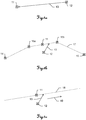
- FIG. 1a shows a novel positioning process for an aircraft schematically.
- the aircraft is here in an actual state, which is defined by an actual position 12, an actual speed and / or an actual orientation, and should assume a desired state.
- the target state of the aircraft is predetermined by a target position 11 and an airspeed (target speed), which should be equal to zero in the target position 11.
- a desired orientation of the aircraft can be defined, wherein the aircraft can be equipped with a measuring sensor for determining the orientation and thus capable of defined self-alignment.
- a correction 13 can now be determined, ie the actual state of the aircraft can be compared with the desired state and from this a difference for the respective state variable (position, speed, orientation) can be calculated. Furthermore, control data or signals can be derived from these state differences and transmitted to the motors of the rotors for controlling the aircraft. Based on the corrections 13, the aircraft can now with a certain Speed and orientation starting from the actual state, in particular from the actual position 12, are controlled such that, for example, an iterative approach to the desired state or to the desired position 11 takes place. In this case, the actual state of the aircraft is continuously compared with the desired state and from there a respective Correction 13 derived. This correction 13 of the actual state of the aircraft can take place until the actual state of the aircraft coincides with the desired state or the difference comes to lie below a predefined threshold value and thus no longer a correction 13 has to be carried out.
- This correction 13 of the actual state of the aircraft can take place until the actual state of the aircraft coincides with the desired state or the difference comes to lie below a
- FIG. 1b an inventive positioning of an aircraft on a given trajectory 17 is shown.
- the trajectory 17 or flight route for the aircraft is limited by a starting point 14 and an end point 15 and their course defined by further waypoints 16a, 16b.
- the aircraft is in an actual state, which in turn may be defined by an actual position 12, an actual speed and / or an actual orientation of the aircraft.
- the actual state can be determined by means of an evaluation unit.
- the desired state (target position 11) of the aircraft is determined in this arrangement by the course of the trajectory 17. Again, corrections 13 are determined by comparing the actual state with the desired state, which are translated into control signals for the aircraft and transmitted to this.
- the current orientation or the direction of flight and the speed can be taken into account, as a result of which the aircraft is not necessarily guided at the shortest distance to the trajectory 17, but is controlled in an optimized direction and with optimized speed to the flight route. For example, this can be a strong deceleration and acceleration of the aircraft and abrupt changes of direction are avoided.
- an optimized reduction of the airspeed can be specified at the waypoints 16a, 16b, 16c at which a change in direction of the trajectory occurs.
- Figure 1c shows an inventive alignment and positioning of an aircraft on a predetermined axis 18. Taking into account the actual state, including the actual position 12, as well as transmitted by a user control signals that can cause a back and forth movement of the aircraft along the axis 18, the corrections 13 are calculated. Analogous to the positioning according to FIG. 1b the movement of the aircraft from the actual position 12 to the target position 11 can be optimized such that in particular the airspeed or control commands additionally input by a user, such as a direction of movement 19, is taken into account in the correction movement 13 and thereby not the shortest distance between actual position 12 and Axis 18 is flown off. In the case shown, the correction movement 13 of the aircraft 20 can be due to a control command in the direction 19 to the right.
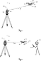
- FIG. 2 shows an inventive surveying system 1 with an unmanned aerial vehicle 20 and a total station 30 representing a measuring unit.
- a detection of the actual state of the aircraft 20, in particular the actual position can here by measurements of the total station 30 or a laser scanner (not here shown).
- the total station 30 is equipped with a pivotable in two axes emission unit 31, whereby an emission direction can be aligned with the aircraft 20. The exact alignment can be detected with angle measuring sensors at the total station 30.
- a distance measuring module is integrated in the emission unit 31, which makes a measurement of a distance to a reflector 22 on the aircraft 20 feasible. From the measured angles and the distance, an actual position or actual coordinates of the aircraft 20 can be determined.
- the surveying device For example via a built-in emission unit 31 camera, or via an external camera, the image field, in particular via a mirror, the aircraft 20 can be aligned with a mark, eg multiple LEDs or defined pattern can be observed and detected at a known position on the housing of the aircraft 20.
- measurement data about the actual state can also be detected with a sensor unit 21, which has, for example, an acceleration sensor, yaw rate sensor, magnetometer, tilt sensor and / or a speed sensor.
- All measurement data can be transmitted, for example, via cable or radio to a control unit 60, which is in this embodiment in the total station 30, but may alternatively be arranged in a remote control or in the aircraft 20.
- the actual state (position, speed, orientation) of the aircraft 20 can then be calculated from the measured data by means of an algorithm, for example with a Kalman filter.
- the measured data can be recorded at different measuring rates.
- the total station 30 may be e.g. the angles and the distance with a measuring rate of e.g. 1 Hz, while the acceleration sensor detects the accelerations acting on it at a rate of e.g. 100 Hz or higher.
- the position determinations by the Kalman filter can thus be made at a rate of e.g. 100 Hz or higher, and thus have a positive effect on the regulation of the aircraft.
- All measurements, e.g. Angle and distance and / or accelerations, inclinations and / or yaw rates from the sensor unit may be fed to the Kalman filter which is continuously fed at a rate of e.g. 100 Hz or higher position coordinates, a velocity vector and / or an orientation angle and any sensor-specific parameters, e.g. calculated the bias of the accelerometer, the aircraft.
- Corrections can be derived from the actual state and control signals which are input, for example, by a user via remote control into the system 1, these corrections being transmitted directly or in the form of further control signals to the engines of the aircraft 20 and a corrected positioning of the aircraft 20 can effect.
- the acquisition of the measurement data for determining the actual state of the aircraft 20 via the total station 30 and a sensor unit 21 can take place.
- the emission unit 31 of the total station 30 can be continuously aligned by an automatic target detection function on the reflector 22 on the aircraft 20 and thus track the aircraft 20.
- the automatic Target tracking due to, for example, a visual obstruction loses the connection to the target (reflector 22)
- a coarse position based on measurements of the sensor unit 21 and / or a GNSS module on the aircraft 20 can be transmitted to the surveying device 30 via radio. Based on this information, the surveying device 30 can retrieve the destination, reestablish the connection, and re-run the automatic tracking.
- the aircraft 20 can be detected and, for example, a contour of the aircraft 20 can be derived by image processing and, based thereon, the surveying unit 30 can be newly aligned with the UAV 20.
- the distance measuring module and by the angle sensors, which are arranged at the total station 30 the distance to the reflector 22 and the orientation of the emission unit 31 and thus the direction of a emitted from the emission unit 31 beam 32, in particular measuring beam, are measured.
- the measurement data can then be forwarded to the control unit 60 in the total station 30.
- the alignment of the aircraft 20 can be determined with the sensor unit 21.
- measurements of an acceleration sensor, a rotation rate sensor, a speed sensor, a tilt sensor and / or a magnetometer which can be arranged in the sensor unit 21 on board the aircraft 20, are used.
- the thus determined measurement data may e.g. be transmitted via radio to the control unit 60.
- the actual state of the aircraft 20 can be calculated from the measured data determined by the total station 30 and by the sensor unit 21 and be adjusted with the specified nominal state. From this, in turn, the corrections can be derived, which can be transmitted by radio to the aircraft 20, and are forwarded there as control signals to the rotors 23 for positioning and alignment.
- FIG. 3 shows a not falling under the claimed invention embodiment of a surveying system 1 with an unmanned aerial vehicle 20 and a laser scanner 40 as a measuring unit.
- the aircraft 20 is given here by emission of an optical beam 42 by the laser scanner 40, a movement axis 43.
- the beam 42 in particular a laser beam
- the beam 42 is emitted via a rotatable mirror 41 in an emission unit in a direction in which the aircraft 20 is to be moved.
- a lateral position deviation and an angular deviation of the aircraft 20 from the predetermined axis 43 are determined by a beam detection unit 25. Additional measurement data, such as the inclinations of the aircraft 20, in turn, can be detected by the sensor unit 21.
- the coupling of the aircraft 20 to the beam 42 can take place, for example, in that a user 100 moves the aircraft 20 by remote control unit 70 to the laser beam 42 or, for example, by the laser beam 42 directed to the detection unit 25, the aircraft 20 coupled and then the beam 42 is aligned in a defined direction, wherein the aircraft 20 remains coupled and is moved along with the realignment of the beam 42 accordingly.
- the measurement data to be detected for determining the actual state can be detected here by means of the beam detection unit 25 on the aircraft 20.
- This beam detection unit 25 may be e.g. consist of a receiving optical system and an image sensor, wherein the laser beam 42 imaged as a laser point in the recorded image and a beam deposition or an angle of incidence can be detected.
- the lateral positional deviation or the angular deviation of the laser beam 42 from an optical axis of the receiving optics can be determined from the position of the laser spot in the image.
- the angular deviation can be detected by means of a collimator associated with the receiving optics. It is also conceivable a detection unit 25, which can detect both the lateral position deviation and the angular deviation with two receiving optics.
- All measurement data can be transmitted via a cable connection or by radio to the control unit 60 on the aircraft and used there to calculate the actual state of the aircraft.
- control data from the user 100 which may cause the aircraft to move back or forth along the axis 43, may be sent to the control unit 60 via the remote control unit 70.
- corrections can be calculated which can be transmitted as control signals to the rotors of the aircraft 20 and an alignment and positioning of the aircraft 20 on the laser beam 20, ie a match of the given direction Movement axis 43 with a optical axis of the beam detection unit 25, cause.
- the lateral beam deposition and the angular deviation can be supplied to the Kalman filter, which is implemented in particular in the control unit 60.
- a semi-autonomous control of the aircraft 20 can be realized such that the system 1, the movement axis 43 is specified as a target state along which the aircraft is to move 20.
- the aircraft 20 can be automatically held on the movement axis 43.
- the back and forth movement along the axis 43 i. a movement of the aircraft 20 with a degree of freedom, can thus be done in a simple manner by the user 100 by means of the remote control unit 70.
- the actual distance can be measured by a distance measurement with the laser scanner 40. From a comparison of this actual distance with the predetermined target distance corrections can be calculated in turn, which are transmitted as control signals for controlling the rotors 23 to the aircraft 20 and can cause a positioning of the aircraft 20 in the given target distance. Since the orientation of the beam 42 emitted by the laser scanner 40 and the distance to the aircraft 20 in this beam direction are known, the position of the aircraft 20 can also be precisely determined or the coordinates with respect to a relative coordinate system of the laser scanner 40 are derived.
- FIGS. 4a and 4b In each case show a further not falling under the claimed invention embodiment of a surveying system 1 with an unmanned aerial vehicle 20 and a rotary laser 50 and are therefore described together here.
- a guide plane 53 or Sollbewegsebene horizontal ( 4a ) or at a certain angle ⁇ to the horizontal H ( 4b ) to hold the aircraft 20 at a constant height and to move or to move in a defined direction.
- such a plane can also be defined with a rotating target unit of a total station by emitting a measuring beam.
- the target unit When using a total station, depending on the horizontal position of the aircraft 20, the target unit can be rotated about the vertical axis and thus the emitted measurement beam can be aligned with the aircraft 20.
- the plane 53 can be spanned by a laser beam 52 rotating rapidly about an axis, independently of the position of the aircraft 20.
- the deviation of the aircraft 20 from a predetermined position by the plane, for example in height, can be detected.
- the inclination and orientation of the aircraft 20 can in turn be determined via the sensor unit 21 on board the aircraft 20.
- These measurement data are transmitted by radio to the control unit 60 integrated with the remote control unit 70 of the user 100. There can be the actual state of the Aircraft 20 are calculated.
- an automatic continuous change of the height of the aircraft 20 can be made such that it is positioned on the predetermined horizontal plane 53 ( 4a ).
- the change in the position of the aircraft 20 in the plane 53 can also be brought about by the user 100 by means of the remote control 70, which can be implemented as a smartphone or tablet PC.
- the user 100 can thus move the aircraft 20 in the plane 53, ie with two remaining degrees of freedom.
- the beam detection unit 25 can be arranged at a corresponding angle on the aircraft 20, or the orientation of the detection unit 25 can be adapted by a pivoting device to the angle ⁇ of the plane 53.
- the user 100 can freely move the aircraft 20 with two degrees of freedom on this inclined plane 53 - indicated by the arrow P -.
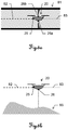
- FIGS. 5a, 5b and 5c show three applications for an aircraft controlled by an inventive surveying aircraft 20.
- FIG. 5a An aircraft 20 is shown having a beam detection unit 23, on which a laser beam 82 is aligned.
- the aircraft 20 can be guided along a movement axis 83.
- the laser beam 82 is aligned coaxially with the axis of a tube 81, which thus coincides with the movement axis 83.
- the aircraft 20 can be moved along the beam 82, for example in a narrow tube 81, by the continuous guidance provided by the beam detection unit 23 so that the distance to the tube wall can be kept constant and a collision with the tube wall can be avoided.
- the aircraft 20 may have distance measuring sensors 26a, 26b, eg scanners, which continuously record distances to the tube wall and provide measured data. This data may be used in addition to the control of the aircraft 20 and taken into account in the calculation of aircraft attitude state correction values. A user can thus very easily manually move and position the aircraft 20 in the tube 81, in particular by means of a remote control.
- FIG. 5b A further application is shown for a guided controlled according to the invention aircraft 20.
- a terrain 85 is to be measured.
- a laser beam 82 aligned in the direction of a horizontal axis 83 and the aircraft 20 by means of a beam receiving unit 25, in particular on the basis of the beam deposition and / or the angle of incidence, at this Beam 82 are moved along.
- an additional sensor 26 which is aligned in the vertical direction down, a distance measurement to the ground surface during a flying over the terrain 85 can be carried out continuously. From this, a distance between the axis 83 and the terrain can be derived in each case and a terrain profile or a terrain section can be created by linking these distance values with the respective actual position of the aircraft 20.
- FIG. 5c A further application for an aircraft 20 controlled according to the invention is shown.
- the aircraft 20 is guided here again in a vertical plane (not shown) defined by a measuring unit by means of the beam receiving unit 25.
- a distance to a surface of an object 85 is measured during the movement of the aircraft 20 and for the determination of a Flight route 86 used for the aircraft 20.
- a constant distance to the object 85 can be maintained during the movement of the aircraft 20 and thus a collision with the object can be avoided.
Landscapes
- Engineering & Computer Science (AREA)
- Aviation & Aerospace Engineering (AREA)
- Radar, Positioning & Navigation (AREA)
- Remote Sensing (AREA)
- Physics & Mathematics (AREA)
- General Physics & Mathematics (AREA)
- Automation & Control Theory (AREA)
- Control Of Position, Course, Altitude, Or Attitude Of Moving Bodies (AREA)
- Optical Radar Systems And Details Thereof (AREA)
- User Interface Of Digital Computer (AREA)
Description
Die Erfindung betrifft ein Vermessungssystem zur Steuerung eines auto-mobilen, unbemannten, steuerbaren Fluggeräts mit einer Vermessungseinheit nach dem Oberbegriff des Anspruchs 1 und ein Verfahren zum Steuern des Fluggeräts nach Anspruch 8.The invention relates to a surveying system for controlling an auto-mobile, unmanned, controllable aircraft with a surveying unit according to the preamble of
Aufgrund einer flexiblen Einsetzbarkeit, sei es zum Erreichen schwer zugänglicher Geländeabschnitte, beispielsweise bei der Feuerbekämpfung oder in Katastrophengebieten, oder zur bildgestützten Überprüfung grosser Objekte, finden unbemannte Fluggeräte heute auf vielen Gebieten der Technik Anwendung. Zur Erfassung von Geländeformationen können derartige Geräte mit Sensoren, beispielsweise mit Kameras, ausgerüstet und grössere Geländeabschnitte damit aus der Luft zusammenhängend aufgenommen werden. Weiterhin können entsprechende Drohnen zu militärischen Zwecken z.B. zur Überwachung, Zielerfassung, als Kampfeinheit oder Transportmittel eingesetzt werden.Due to a flexible applicability, be it to reach hard to reach terrain sections, for example in the field of fire fighting or in disaster areas, or for image-based review of large objects, unmanned aerial vehicles today in many fields of technology application. For the detection of terrain formations, such devices can be equipped with sensors, for example with cameras, and larger terrain sections can thus be recorded coherently from the air. Furthermore, corresponding drones can be used for military purposes, eg for surveillance, targeting, combat units or means of transport.
In
Eine Steuerung bzw. Bewegung eines unbemannten Fluggeräts kann prinzipiell manuell mittels einer Fernsteuerung durch einen Benutzer oder vollständig autonom bzw. semi-autonom, zumeist auf Basis von GNSS-Positionsinformationen, erfolgen.In principle, a control or movement of an unmanned aerial vehicle can take place manually by means of a remote control by a user or completely autonomously or semi-autonomously, generally on the basis of GNSS position information.
Im Allgemeinen können bei einer Bewegung des Fluggeräts, beispielsweise bei einem helikopter-ähnlichen Fluggerät, vier von sechs Freiheitsgraden geändert werden, d.h. das Fluggerät kann vor und zurück, links und rechts sowie auf und ab bewegt werden. Zudem kann durch eine Drehung um die vertikale Achse die Ausrichtung des Fluggeräts verändert werden. Die verbleibenden zwei Freiheitsgrade sind durch die im Wesentlichen horizontale Lage des Fluggeräts festgelegt.In general, in a movement of the aircraft, for example in a helicopter-like aircraft, four of six degrees of freedom can be changed, ie the aircraft can be moved back and forth, left and right and up and down. In addition, by turning around the vertical axis the orientation of the aircraft are changed. The remaining two degrees of freedom are determined by the substantially horizontal position of the aircraft.
Eine präzise Positionierung in einer vorgegebenen Position oder eine präzise Bewegung z.B. entlang einer vordefinierten Achse oder Flugroute erweist sich bei der manuellen Steuerung für einen Benutzer als schwierig. Insbesondere dann, wenn das Fluggerät äusseren Einflüssen, wie z.B. Wind, ausgesetzt ist und die dadurch entstehenden Abweichungen reaktionsschnell kompensiert werden müssen, kann bei einer derartigen manuellen Steuerung eine geforderte Genauigkeit oftmals nicht eingehalten werden.Precise positioning in a given position or precise movement e.g. along a predefined axis or flight route proves difficult for a user in manual control. In particular, when the aircraft is subject to external influences, such as Wind, is exposed and the resulting deviations must be quickly compensated, a required accuracy can often not be met in such a manual control.
Weiters ist der Einsatzbereich für eine autonome GNSSbasierte Steuerung limitiert auf Orte, an denen eine für die Positionsbestimmung ausreichende Anzahl von Satellitensignalen empfangen werden kann. Ein Einsatz z.B. in geschlossenen Räumen oder Tunneln ist somit im Allgemeinen nicht möglich. Auch der Einsatz in dicht bebauten Gebieten kann bei einer Abschirmung von GNSS-Signalen durch Gebäude sich als schwierig erweisen.Furthermore, the scope for autonomous GNSS-based control is limited to locations where a sufficient number of satellite signals can be received for positioning. An insert, e.g. in closed rooms or tunnels is therefore generally not possible. Even in densely built-up areas, shielding GNSS signals from buildings can be difficult.
Zur Steuerung eines Fluggeräts in einem derart bebauten Gebiet schlägt die
In der
Bei einer autonomen Steuerung kann dem Fluggerät ferner die Route in Form einer Trajektorie, z.B. definiert durch mehrere Wegpunktpositionen, vorgegeben werden. In der
Den genannten Methoden bzw. Systemen ist gemein, dass die Lage des Fluggeräts mittels GNSS-Sensoren, insbesondere die vertikale Position, nur bis auf 2-5 cm genau bestimmt werden kann. Diese Unsicherheit wirkt sich im Weiteren stark limitierend auf die Genauigkeit bei einer Positionsbestimmung des Fluggeräts und auf die Genauigkeit bei der Steuerung des Fluggeräts aus.The methods and systems mentioned have in common that the position of the aircraft by means of GNSS sensors, in particular the vertical position, can only be determined accurately to within 2-5 cm. This uncertainty has a further limiting effect on the accuracy in determining the position of the aircraft and on the accuracy of the control of the aircraft.
Aufgabe der vorliegenden Erfindung ist es demnach, ein verbessertes, robusteres System bzw. Verfahren zur Steuerung eines unbemannten Fluggeräts bereitzustellen, mit welchen das Fluggerät benutzerfreundlicher, präziser und mit einem höheren Automatisierungsgrad positioniert und bewegt werden kann. Eine spezielle Aufgabe der Erfindung ist es, diese Positionierung und Bewegung des Fluggeräts unabhängig von einer Empfangbarkeit von GNSS-Signalen durchführbar zu machen.The object of the present invention is therefore to provide an improved, more robust system or method for controlling an unmanned aerial vehicle, with which the aircraft can be positioned and moved in a user-friendly, precise and with a higher degree of automation. A specific object of the invention is to make this positioning and movement of the aircraft independently of a reception of GNSS signals feasible.
Diese Aufgaben werden durch die Verwirklichung der kennzeichnenden Merkmale der unabhängigen Ansprüche gelöst. Merkmale, die die Erfindung in alternativer oder vorteilhafter Weise weiterbilden, sind den abhängigen Patentansprüchen zu entnehmen.These objects are achieved by the realization of the characterizing features of the independent claims. Features which further develop the invention in an alternative or advantageous manner can be found in the dependent claims.
Das System zur Steuerung des unbemannten Fluggeräts (UAV = Unmanned Aerial Vehicle) weist einen Theodolit, eine Totalstation, einen Lasertracker, einen Laserscanner oder einen Rotationslaser und eine Steuereinheit auf. Die Steuereinheit kann mittels Steuersignalen eine Positionierung oder Bewegung des Fluggeräts erwirken, indem dadurch z.B. eine Rotationsgeschwindigkeit der, insbesondere vier, Rotoren des Fluggeräts oder eine jeweilige Ausrichtung der Rotoren definiert einstellbar ist. Das jeweilige Vermessungsgerät steht dabei mit dem Fluggerät beispielsweise durch einen vom Vermessungsgerät emittierten Laserstrahl und/oder durch Funksignale in Kontakt. Mittels des Laserstrahls und einem am Fluggerät angebrachten Reflektor kann durch Reflexion des Strahls und Empfangen am Vermessungsgerät eine Entfernung des Fluggeräts zum Vermessungsgerät bestimmt werden. Durch Winkelmesser am Vermessungsgerät können ferner ein Vertikal- und Horizontalwinkel des emittierten Strahls, also eine Emissionsrichtung, erfasst und in Kombination mit der bestimmten Entfernung daraus eine Position des Fluggeräts zum Vermessungsgerät in einem relativen Koordinatensystem geodätisch genau bestimmt werden.The Unmanned Aerial Vehicle (UAV) system includes a theodolite, a total station, a laser tracker, a laser scanner or a rotating laser, and a control unit. The control unit may obtain, by means of control signals, a positioning or movement of the aircraft, e.g. a rotational speed of, in particular four, rotors of the aircraft or a respective orientation of the rotors is defined adjustable. The respective surveying device is in contact with the aircraft, for example, by a laser beam emitted by the surveying device and / or by radio signals. By means of the laser beam and a reflector attached to the aircraft, a distance of the aircraft to the surveying device can be determined by reflection of the beam and reception at the surveying device. By means of protractors on the surveying device, furthermore, a vertical and horizontal angle of the emitted beam, ie an emission direction, can be detected and, in combination with the determined distance, a position of the aircraft relative to the surveying device can be determined geodetically in a relative coordinate system.
In einer nicht unter die beanspruchte Erfindung fallenden Variante kann der Laserstrahl z.B. in einer Kombination Fluggerät/Rotationslaser seitens des Fluggeräts durch eine Laserstrahlempfangseinheit empfangen werden. Mittels dieser Einheit kann ein Einfallswinkel des Laserstrahls relativ zur Empfangseinheit bestimmt und daraus eine relative Ausrichtung des Fluggeräts zum Laserstrahl (Istzustand des Fluggeräts) mit einer Auswerteeinheit abgeleitet werden. Zudem kann eine Ablage des Strahls aus einer definierten Nullposition der Empfangseinheit bestimmt und daraus wiederum eine relative Position des Fluggeräts zum Laserstrahl abgeleitet werden. Aus der jeweiligen Ablage und/oder dem Einfallswinkel können Korrekturparameter ermittelt werden, die dazu dienen das Fluggerät derart zu steuern, dass eine Sollposition und Sollausrichtung erreicht wird, wobei bei Erreichen des Sollzustands die Ablage bzw. der relative Einfallswinkel jeweils die Nulllage, d.h. keine Abweichung vom einem Sollwert aufweisen, einnehmen. In a variant not falling under the claimed invention , the laser beam can be received, for example, in a combination aircraft / rotary laser from the aircraft by a laser beam receiving unit. By means of this unit, an angle of incidence of the laser beam relative to the receiving unit can be determined and from this a relative orientation of the aircraft to the laser beam (actual state of the aircraft) can be derived with an evaluation unit. In addition, a storage of the beam from a defined zero position of the receiving unit determines and in turn a relative position of the aircraft to Laser beam are derived. From the respective storage and / or the angle of incidence correction parameters can be determined, which serve to control the aircraft such that a desired position and target orientation is achieved, upon reaching the desired state, the filing or the relative angle of incidence respectively the zero position, ie no deviation from a setpoint, take.
Mit einer derartigen Empfangseinheit kann das Fluggerät ausserdem an einen Laserstrahl angekoppelt werden. Beispielsweise kann dieser Strahl von einem Laserscanner emittiert werden und das Fluggerät von einem Benutzer mit einer Fernsteuerung so gesteuert werden, dass der Laserstrahl auf die Empfangseinheit trifft. Sobald der Strahl empfangen wird, kann dann eine Recheneinheit im Fluggerät die Steuerung zumindest teilweise übernehmen. In einem Regelkreis kann die aktuelle Position, die Orientierung, die Geschwindigkeit und Flugrichtung des Fluggeräts fortlaufend ermittelt werden und so ausgeglichen oder korrigiert werden, dass der Laserstrahl zentral, d.h. ohne Abweichungen aus der Nulllage, in die Empfangseinheit trifft. Der Benutzer kann jetzt mit der Fernsteuerung das Fluggerät entlang des Laserstrahls, also mit einem verbleibenden Freiheitsgrad, bewegen. In dieser Konfiguration kann nun zusätzlich oder alternativ durch eine Neuausrichtung bzw. durch ein Schwenken des emittierten Strahls das Fluggerät geführt werden. Wird anstelle des Laserscanners z.B. ein Rotationslaser eingesetzt, kann damit eine Laserebene aufgespannt werden und das Fluggerät auf diese Ebene "gesetzt" werden. Auch hier kann der Benutzer - jetzt mit zwei Freiheitsgraden - das Fluggerät in der Ebene bzw. parallel dazu bewegen. Die Ebene oder Strahl können z.B. horizontal ausgerichtet werden und so eine horizontale Bewegung des Fluggeräts bewirken. Ausserdem können diese in einem beliebigen Winkel oder vertikal ausgerichtet werden, insbesondere wobei bei einer vertikalen Ausrichtung die Höhe des Fluggeräts über dem Boden frei wählbar bleiben kann. Eine derartige Anwendung kann beispielsweise bei Arbeiten entlang oder für eine Vermessung einer Gebäudefassade nützlich sein.With such a receiving unit, the aircraft can also be coupled to a laser beam. For example, this beam may be emitted by a laser scanner and the aircraft controlled by a user with a remote control so that the laser beam strikes the receiving unit. As soon as the beam is received, an arithmetic unit in the aircraft can then at least partially take over the control. In a control loop, the current position, orientation, speed and direction of flight of the aircraft can be continuously determined and compensated or corrected so that the laser beam centrally, ie without deviations from the zero position, in the receiving unit. The user can now use the remote control to move the aircraft along the laser beam, ie with a remaining degree of freedom. In this configuration, the aircraft can now additionally or alternatively be guided by a realignment or by a pivoting of the emitted beam. If, for example, a rotating laser is used instead of the laser scanner, a laser plane can thus be spanned and the aircraft "set" to this plane. Again, the user - now with two degrees of freedom - the aircraft in the plane or move parallel to it. The For example, plane or beam can be aligned horizontally, thus causing a horizontal movement of the aircraft. In addition, these can be aligned at any angle or vertically, in particular, wherein in a vertical orientation, the height of the aircraft can remain freely selectable above the ground. Such an application may be useful, for example, when working along or surveying a building facade.
Je nach Ausgestaltung der Laserstrahlempfangseinheit kann der zu detektierende Einfallswinkelbereich auf einen Bereich beispielsweise zwischen 0° und 180°, insbesondere zwischen 0° und 45°, beschränkt sein. Damit muss, um ein kontinuierliches Empfangen des Strahls zu gewährleisten, die Anordnung der Empfangseinheit am Fluggerät an die jeweilige Ausrichtung des Laserstrahls bzw. der Laserebene angepasst sein. Bei einer horizontalen Stahlausrichtung kann die Laserstrahlempfangseinheit z.B. seitlich am UAV angebracht, bei einer vertikalen Ausrichtung z.B. an der Unterseite des UAVs angeordnet sein. Für einen universellen Einsatz des Fluggeräts kann die Laserstrahlempfangseinheit ferner derart schwenkbar am Fluggerät angebracht sein, dass die Empfangseinheit je nach Ausrichtung des Laserstrahls in eine bestimmte Winkelstellung geschwenkt und damit den Strahl innerhalb des strukturell vorgegebenen Erfassungsbereichs empfangen kann. Auch zur Bestimmung der Strahlablage kann, abhängig von der Strahlausrichtung, die Anordnung der Empfangseinheit angepasst bzw. eine Haupterfassungsrichtung der Empfangseinheit schenkend zum Strahl ausgerichtet werden.Depending on the configuration of the laser beam receiving unit, the range of incident angles to be detected may be restricted to a range of, for example, between 0 ° and 180 °, in particular between 0 ° and 45 °. Thus, in order to ensure a continuous reception of the beam, the arrangement of the receiving unit on the aircraft must be adapted to the respective orientation of the laser beam or the laser plane. In a horizontal steel orientation, the laser beam receiving unit may e.g. attached laterally to the UAV, in a vertical orientation e.g. be arranged on the underside of the UAVs. For a universal use of the aircraft, the laser beam receiving unit may further be pivotally mounted on the aircraft so that the receiving unit can be pivoted depending on the orientation of the laser beam in a specific angular position and thus receive the beam within the structurally predetermined detection range. Depending on the beam alignment, the arrangement of the receiving unit can also be adapted or a main scanning direction of the receiving unit can be aligned with the beam in order to determine the beam deposition.
Prinzipiell kann für die Steuerung des UAV fortlaufend ein Istzustand des Fluggeräts im relativen Koordinatensystem, d.h. ein Zustand, der beispielsweise zumindest teilweise eine aktuelle Position, eine aktuelle Ausrichtung, eine Geschwindigkeit und/oder eine Flugrichtung des Fluggeräts beschreibt, durch ein Zusammenwirken mit der Vermessungseinheit bestimmt werden. Zudem kann ein Sollzustand für das Fluggerät mit einem in Zusammensetzung und Format zum Istzustand korrespondierenden Informationsgehalt im Vermessungssystem vorgegeben werden. Auf Basis des so bestimmten Istzustands und des definierten, von Fluggerät zu erreichenden Sollzustands können durch einen Zustandsvergleich Korrekturwerte ermittelt werden, mittels derer die gezielte Steuerung des Fluggeräts hin zum Sollzustand realisierbar ist. Aus den Korrekturen können somit Steuerungsdaten abgeleitet und dem Fluggerät beispielsweise zur Ansteuerung der Rotoren zur Verfügung gestellt werden. Die Korrektur- bzw. Steuerungsdaten können durch die Steuereinheit ermittelt werden, wobei die Steuereinheit dabei der Vermessungseinheit, dem Fluggerät oder der Fernsteuerung zugeordnet oder als weiter strukturell eigenständige Einheit ausgebildet sein kann.In principle, for the control of the UAV continuously an actual state of the aircraft in the relative coordinate system, ie, a state, for example, at least partially describes a current position, a current orientation, a speed and / or a direction of flight of the aircraft, be determined by an interaction with the surveying unit. In addition, a desired state for the aircraft can be specified in the surveying system with an information content corresponding to the actual state in terms of composition and format. On the basis of the thus determined actual state and the defined target state to be reached by the aircraft, correction values can be determined by means of a state comparison, by means of which the targeted control of the aircraft towards the desired state can be realized. Control data can thus be derived from the corrections and made available to the aircraft, for example for controlling the rotors. The correction or control data can be determined by the control unit, wherein the control unit can be assigned to the measurement unit, the aircraft or the remote control or designed as a further structurally independent unit.
Dem System können ferner ein Einzelpunkt, eine Trajektorie, eine Achse und/oder eine Ebene als Sollzustand bzw. Sollposition vorgegeben und das Fluggerät entsprechend der jeweiligen Vorgabe, insbesondere durch ein fortlaufendes Vergleichen von Soll- und Istwerten und ein iteratives Neupositionieren, positioniert und bewegt werden. Eine Trajektorie bzw. eine Flugroute kann z.B. durch einen Startpunkt und einen Endpunkt festgelegt werden, wobei das Fluggerät in diesem Fall auf einer geraden Verbindungslinie vom Start- zum Endpunkt manuell, autonom oder semi-autonom, d.h. das Fluggerät bewegt sich im Wesentlichen selbstständig, ein Benutzer kann jedoch in den Bewegungsablauf eingreifen und diesen beispielsweise vorübergehend unterbrechen, geführt werden kann. Zwischen dem Start- und Endpunkt können weitere Wegpunkte definiert werden und die Flugroute, insbesondere automatisch, so angepasst werden, dass die Wegpunkte auf der Route liegen. Ferner kann die abzufliegende Flugroute unabhängig von Start-, End- und Wegpunkten, sondern durch die Lage einer Bewegungsachse definiert werden. Für die Steuerung des Fluggeräts kann bei einer definierten Flugroute ein Vergleich des Routenverlaufs mit dem aktuellen Istzustand des Fluggeräts vorgenommen werden und auf dieser Basis die jeweiligen Korrekturwerte bzw. Steuerungsdaten ermittelt werden. Dabei kann zur Optimierung der Flugbewegung des Fluggeräts bei einer notwendigen Positionskorrektur hin zur Flugroute anstelle einer direkten Bewegung, d.h. anstelle einer Bewegung entlang der kürzesten Verbindung zwischen Istposition und Flugroute, eine optimierte Korrekturbewegung z.B. unter Berücksichtigung der aktuellen Flugrichtung und Geschwindigkeit des Fluggeräts erfolgen.Furthermore, the system can specify a single point, a trajectory, an axis and / or a plane as desired state or target position and position and move the aircraft according to the respective specification, in particular by continuously comparing setpoint and actual values and repositioning iteratively , A trajectory or a flight route can be determined, for example, by a starting point and an end point, in which case the aircraft moves on a straight connecting line from the start to the end point manually, autonomously or semi-autonomously, ie the aircraft moves essentially independently Users can however in the Intervene movement and this example, temporarily interrupt, can be performed. Between the start and end points further waypoints can be defined and the flight route, in particular automatically, be adjusted so that the waypoints are on the route. Furthermore, the flight path to be dropped can be defined independently of start, end and waypoints, but by the position of a movement axis. For the control of the aircraft can be made at a defined flight route, a comparison of the route with the current state of the aircraft and on this basis, the respective correction values or control data are determined. In this case, to optimize the flight movement of the aircraft in a necessary position correction towards the flight route instead of a direct movement, ie instead of a movement along the shortest connection between actual position and flight route, an optimized correction movement, for example, taking into account the current direction and speed of the aircraft.
Neben Messungen des Vermessungsgeräts können auch Messungen einer am Fluggerät angeordneten Sensoreinheit zur Bestimmung der Ausrichtung des Fluggeräts und/oder der Geschwindigkeit im relativen Koordinatensystem zur Bestimmung von Korrekturen verwendet werden. Die Sensoreinheit kann hierfür Trägheitswerte, z.B. mittels eines Beschleunigungssensors, und eine geografische Ausrichtung, z.B. durch ein Magnetometer, erfassen. Die Korrekturen können ebenfalls in Steuersignale für das Fluggerät übersetzt werden und damit eine Änderung der Position, der Ausrichtung, der Geschwindigkeit und/oder der Flugrichtung bewirken.In addition to measurements of the surveying device, measurements of a sensor unit arranged on the aircraft for determining the orientation of the aircraft and / or the speed in the relative coordinate system can also be used to determine corrections. For this purpose, the sensor unit can detect inertia values, for example by means of an acceleration sensor, and a geographical orientation, for example by a magnetometer. The corrections may also be translated into control signals for the aircraft, thereby causing a change in position, orientation, speed and / or heading.
Weiter können zur Bestimmung der Ausrichtung des Fluggeräts Markierungen, z.B. definierte Muster, Pseudo-Random-Patterns oder Leuchtmittel, in einer bestimmten Lage und Anordnung am Fluggerät angebracht sein und eine externe Erfassungseinheit diese Markierungen erfassen. Die Erfassungseinheit, insbesondere eine Kamera, kann hierfür am Vermessungsgerät angeordnet oder als eigenständige Einheit ausgebildet sein. Die Lage von zumindest Teilen der Markierungen auf einem von der Kamera erfassten Bild kann dann einen Rückschluss auf die Ausrichtung des Fluggeräts im relativen Koordinatensystem zulassen. Ferner kann das Fluggerät mit einer RIM-Kamera (Range Imaging Kamera) erfasst und damit ein Bild mit punktaufgelösten Abstandswerten von der RIM-Kamera zum Fluggerät erfasst werden. Aus diesen Daten kann somit ebenfalls die Entfernung und bei Kenntnis der Form des Fluggeräts die Ausrichtung des Fluggeräts abgeleitet werden.Further, to determine the orientation of the aircraft, markers, e.g. defined patterns, pseudo-random patterns or bulbs, be mounted in a specific location and arrangement on the aircraft and capture an external detection unit these markers. The detection unit, in particular a camera, can for this purpose be arranged on the surveying device or designed as an independent unit. The location of at least parts of the markings on an image captured by the camera can then allow a conclusion about the orientation of the aircraft in the relative coordinate system. Furthermore, the aircraft can be detected with a RIM camera (Range Imaging Camera) and thus an image with point-resolved distance values from the RIM camera to the aircraft are detected. From this data can thus also the distance and with knowledge of the shape of the aircraft, the orientation of the aircraft are derived.
Mit an dem Fluggerät angeordneten Abstandsmesssensoren können ausserdem weitere Anwendungen ermöglicht werden. Dabei kann beispielsweise die Steuerung des Fluggeräts derart erfolgen, dass ein Abstand zu einem Objekt z.B. auf 40 cm, insbesondere zur Kollisionsvermeidung oder Beibehaltung eines optimalen Messabstands für einen zusätzlich Datenerfassungssensor (z.B. Scanner oder Kamera), konstant gehalten werden kann. Z.B. kann somit eine verlässliche Steuerung des Fluggeräts in Umgebungen mit begrenztem Platzangebot durchgeführt werden, indem durch die Abstandssensoren allfällige Hindernisse detektiert und umflogen werden können bzw. räumliche Begrenzungen, z.B. bei einem Flug durch ein Rohr, eine Pipeline oder einen Tunnel, fortlaufend gemessen und die Position des Fluggeräts entsprechend angepasst werden kann.With arranged on the aircraft distance measurement sensors also other applications can be made possible. In this case, for example, the control of the aircraft can be such that a distance to an object, for example, to 40 cm, in particular for collision avoidance or maintaining an optimal measurement distance for an additional data acquisition sensor (eg scanner or camera), can be kept constant. Thus, for example, a reliable control of the aircraft in environments with limited space can be carried out by any obstacles can be detected and flown through the distance sensors or spatial limitations, eg in a flight through a pipe, a pipeline or a tunnel, continuously measured and the Position of the aircraft can be adjusted accordingly.
Bei einer derartigen raumbegrenzten Bewegung kann das Fluggerät insbesondere an einen Laserstrahl gekoppelt und anhand dieses Strahls geführt werden. Mit einer derartigen Kombination aus Abstandsmessung und Führung anhand eines Strahls kann ferner beispielsweise bei horizontaler Ausrichtung des Führungsstrahls, Bewegung des Fluggeräts entlang dieses Strahls und einer kontinuierlichen Abstandsmessung zum überflogenen Gelände durch eine Verknüpfung von jeweiligen Anstandsmessungen und jeweiligen Fluggerätpositionen ein Geländeprofil bzw. ein Geländeschnitt erstellt werden.In such a space-limited movement, the aircraft can in particular be coupled to a laser beam and guided by this beam. With such a combination of distance measurement and guidance by means of a beam, a terrain profile or a terrain section can also be created, for example in the case of horizontal alignment of the guide beam, movement of the aircraft along this beam and continuous distance measurement to the overflown terrain by linking respective propriety measurements and respective aircraft positions ,
Insbesondere kann die Position der Vermessungseinheit, d.h. deren Aufstellpunkt, durch einen bekannten Punkt vorgegeben sein und eine Ausrichtungsbestimmung durch ein Anmessen eines bekannten Zielpunkts oder mittels eines Neigungssensors und eines Magnetometers erfolgen. Die Positions- und Ausrichtungsbestimmung kann ausserdem, insbesondere dann wenn der Aufstellpunkt nicht bekannt ist, durch ein Anzielen mindestens dreier Zielpunkte durchgeführt werden. Durch dieses Vorgehen können die Position und die Koordinaten der Vermessungseinheit und die Orientierung der Vermessungseinheit in einem globalen, dem relativen Koordinatensystem übergeordneten, Koordinatensystem bestimmt werden. Ferner kann die Richtung der Bewegungsachse im globalen Koordinatensystem gegeben sein. Mit dieser Kenntnis kann nun eine Referenzierung des relativen mit dem globalen Koordinatensystem, z.B. durch Koordinatentransformation, erfolgen. Damit können die im relativen Koordinatensystem bestimmte Position und Ausrichtung des UAVs in das globalen Koordinatensystem übertragen und z.B. eine absolute Position und Ausrichtung des UAVs in diesem übergeordneten Koordinatensystem angegeben werden.In particular, the position of the measuring unit, ie its set-up point, can be predetermined by a known point and an orientation determination can be made by measuring a known target point or by means of an inclination sensor and a magnetometer. The position and orientation determination can also, in particular if the set-up point is not known, be carried out by aiming at least three target points. By doing so, the position and coordinates of the surveying unit and the orientation of the surveying unit can be determined in a global coordinate system superordinate to the relative coordinate system. Furthermore, the direction of the movement axis can be given in the global coordinate system. With this knowledge, a referencing of the relative with the global coordinate system, eg by coordinate transformation, can now take place. Thus, the position and orientation of the UAV determined in the relative coordinate system can be transferred into the global coordinate system and, for example, an absolute position and orientation of the UAV in this parent coordinate system.
Die Erfindung betrifft ein geodätisches Vermessungssystem mit einer geodätischen Vermessungseinheit, die als Totalstation, Theodolit, Lasertracker oder Laserscanner ausgebildet ist, mit einer Strahlquelle zur Emission eines im Wesentlichen kollimierten optischen Strahls, einer Basis, einer relativ zur Basis um zwei Achsen motorisiert schwenkbaren Anzieleinheit zur Ausrichtung einer Emissionsrichtung des optischen Strahls und Winkelmesssensoren zur Bestimmung der Ausrichtung der Anzieleinheit, sowie insbesondere mit einer Entfernungsmessfunktionalität. Zudem weist das Vermessungssystem ein auto-mobiles, unbemanntes, steuerbares Fluggerät mit einem optischen Modul auf, wobei das Fluggerät derart ausgebildet ist, dass das Fluggerät gesteuert bewegbar und im Wesentlichen positionsfest positionierbar ist. Ausserdem ist eine Auswerteeinheit vorgesehen, wobei die Auswerteeinheit derart konfiguriert ist, dass aus einer Zusammenwirkung des optischen Strahls mit dem optischen Modul ein durch eine Lage, eine Ausrichtung und/oder eine Lageänderung bestimmter Istzustand des Fluggeräts in einem Koordinatensystem bestimmbar ist. Das Vermessungssystem weist eine Steuereinheit zur Steuerung des Fluggeräts auf, wobei die Steuereinheit derart konfiguriert ist, dass anhand eines Algorithmus in Abhängigkeit des, insbesondere fortlaufend bestimmbaren, Istzustands und eines definierten Sollzustands Steuerdaten erzeugbar sind und das Fluggerät mittels der Steuerdaten in den Sollzustand, insbesondere in einen definierten Toleranzbereich um den Sollzustand, automatisch gesteuert bringbar ist.The invention relates to a geodetic surveying system comprising a geodetic survey unit, which is designed as a total station, theodolite, laser tracker or laser scanner with a beam source for emitting a substantially collimated optical beam, a base, a motorized relative to the base about two axes pivotable targeting moiety for alignment an emission direction of the optical beam and angle measuring sensors for determining the orientation of the targeting unit, and in particular with a distance measuring functionality. In addition, the surveying system to an auto-mobile, unmanned, controllable aircraft with an optical module, wherein the aircraft is designed such that the aircraft is controlled movable and substantially positionally fixed position. In addition, an evaluation unit is provided, wherein the evaluation unit is configured in such a way that from an interaction of the optical beam with the optical module, an actual state of the aircraft determined by a position, an orientation and / or a position change can be determined in a coordinate system. The measuring system has a control unit for controlling the aircraft, wherein the control unit is configured such that control data can be generated by means of an algorithm in dependence on the, in particular continuously determinable, actual state and a defined desired state control data and the aircraft by means of the control data in the desired state, in particular a defined tolerance range around the target state, automatically controlled can be brought.
Die Anzieleinheit der geodätischen Vermessungseinheit kann in einer Ausführungsform als eine die Strahlquelle aufweisende Emissionseinheit (mit Teleskopeinheit) ausgebildet sein. Eine derartige Ausführung kann insbesondere zum Aufbau einer Totalstation oder eines Theodoliten realisiert sein.The targeting unit of the geodetic surveying unit can in one embodiment be designed as an emission unit (with telescope unit) having the beam source. Such an embodiment can be realized in particular for the construction of a total station or a theodolite.
Hinsichtlich der Konstruktion von Lasertrackern oder Laserscannern kann die Strahlquelle beispielsweise in einer Stütze, die um eine durch die Basis definierte Stehachse relativ zur Basis schwenkbar ausgeführt ist, oder in der Basis vorgesehen sein, wobei die emittierte Strahlung mittels optischer Strahlführungselemente zur Anzieleinheit geführt werden kann. In diesem Zusammenhang kann die Anzieleinheit beispielsweise als Strahlumlenkelement (z.B. Spiegel) ausgebildet sein.With regard to the construction of laser trackers or laser scanners, the beam source can be provided, for example, in a support which is pivotable about a standing axis defined by the base relative to the base, or in the base, whereby the emitted radiation can be guided to the target unit by means of optical beam guidance elements. In this connection, the targeting unit may be formed, for example, as a beam deflecting element (e.g., mirror).
Im erfindungsgemässen geodätischen Vermessungssystem kann bei der Bestimmung des Istzustands eine Istposition, eine Istausrichtung und/oder eine Istgeschwindigkeit des Fluggeräts und/oder bei der Definition des Sollzustands eine Sollposition, eine Sollausrichtung und/oder eine Sollgeschwindigkeit berücksichtigbar sein.In the geodetic surveying system according to the invention, when determining the actual state, an actual position, an actual orientation and / or an actual speed of the aircraft and / or in the definition of the setpoint state a setpoint position, a setpoint orientation and / or a setpoint speed can be taken into account.
In einem derartigen System kann fortlaufend ein Zustand des Fluggeräts, z.B. die Position, die Ausrichtung, die Fluggeschwindigkeit oder -ausrichtung, bestimmt werden. Die Vermessungseinheit kann dafür einen Laserstrahl emittieren, der mit einem Sensor oder Reflektor am Fluggerät wechselwirken kann. Auf Basis dieser Wechselwirkung kann dann die Zustandsermittlung für das Fluggerät durchgeführt werden. Zudem kann ein Sollzustand für das Fluggerät, beispielsweise eine Position an der das UAV positioniert werden soll, definiert werden und durch einen Vergleich des ermittelten Istzustands des Fluggeräts mit diesem Sollzustand die Steuerung des Fluggeräts derart erfolgen, dass das Fluggerät hin zum Sollzustand bewegt bzw. ausgerichtet wird und den Sollzustand einnimmt, somit also z.B. die Istposition mit der Sollposition übereinstimmt. Für diesen Regelvorgang werden anhand eines Algorithmus Steuerdaten zur Steuerung des Fluggeräts erzeugt. Dabei können z.B. einem Kalmanfilter die erzeugten Messdaten bzw. die Istposition und -ausrichtung des Fluggeräts zugeführt werden und aus der Summe der Daten die Steuerdaten unter Berücksichtigung eines definierten Sollzustands generiert werden. Zur Ermittlung der Steuerdaten können zudem aus den Messgrössen Mittelwerte abgeleitet werden. Ferner kann fortlaufend eine Differenzbildung einzelner Soll-Ist-Grössenpaare durchgeführt werden und z.B. auf Basis einer so bestimmten Positionsdifferenz eine Richtung und Entfernung zur Sollposition bestimmt und die Steuerdaten hinsichtlich Flugrichtung, Flugstrecke und Fluggeschwindigkeit abgeleitet werden. Damit können beispielsweise die Rotoren des Fluggeräts derart angesteuert werden, dass insbesondere durch unterschiedliche Rotationsgeschwindigkeiten eine gesteuerte Bewegung des Fluggeräts hin zur Sollposition erfolgt. Ausserdem kann im Rahmen des Algorithmus eine fortlaufende Neubewertung und Berechnung der Steuerdaten aus einem fortlaufenden Vergleich der Istposition mit der Sollposition erfolgen, wodurch die Position des Fluggeräts durch einen derartigen Regelkreis ständig nachgeregelt werden kann.In such a system, a state of the aircraft, such as position, orientation, airspeed or orientation, may be continuously determined. The measuring unit can emit a laser beam for this, which can interact with a sensor or reflector on the aircraft. Based on this interaction, the state determination for the aircraft can then be carried out. In addition, a desired state for the aircraft, for example, a position at which the UAV is to be positioned, are defined and by comparing the determined actual state of the aircraft with this target state, the control of the aircraft carried out such that the aircraft is moved towards the target state or aligned and assumes the desired state, thus thus eg the actual position coincides with the target position. For this control process, control data for controlling the aircraft is generated by means of an algorithm. In this case, for example, the Kalman filter the measured data generated or the actual position and orientation of the aircraft are supplied and generated from the sum of the data, the control data taking into account a defined target state. To determine the control data, mean values can also be derived from the measured variables. Furthermore, a difference formation of individual desired-actual size pairs can be carried out continuously and, for example, on the basis of a position difference determined in this way, a direction and distance to the desired position determined and the control data with respect to flight direction, route and airspeed derived. Thus, for example, the rotors of the aircraft can be controlled such that, in particular by different rotational speeds, a controlled movement of the aircraft takes place towards the desired position. Furthermore, within the framework of the algorithm, a continuous reassessment and calculation of the control data can take place from a continuous comparison of the actual position with the desired position, as a result of which the position of the aircraft can be constantly readjusted by means of such a control loop.
Das optische Modul des erfindungsgemässen geodätischen Vermessungssystems ist durch einen die Istposition des Fluggeräts angebenden Reflektor verkörpert, wobei der
Strahl mittels des Reflektors reflektierbar ist und wobei eine Entfernung von der Vermessungseinheit zum Fluggerät bestimmbar und die Istposition des Fluggeräts, insbesondere fortlaufend, aus der Entfernung und der Emissionsrichtung des Strahls ableitbar ist. The optical module of the geodetic surveying system according to the invention is embodied by a reflector indicating the actual position of the aircraft , wherein the
Beam is reflected by means of the reflector and wherein a distance from the surveying unit to the aircraft can be determined and the actual position of the aircraft, in particular continuously, from the distance and the emission direction of the beam can be derived.
Indem z.B. mit einem Laserstrahl der Reflektor am Fluggerät angezielt wird, kann der Istzustand, insbesondere die Istposition, des Fluggeräts mit der Vermessungseinheit, z.B. mit einer Totalstation, ermittelt werden. Hierfür können der reflektierte, am Vermessungsgerät erfasste Strahl zur Entfernungsmessung und die erfassten Winkel, mit denen der Strahl emittiert wird, zur Richtungsbestimmung herangezogen werden und daraus eine Position und Ausrichtung des Fluggeräts relativ zur Position der Vermessungseinheit abgeleitet werden.By e.g. with a laser beam the reflector is aimed at the aircraft, the actual state, in particular the actual position, of the aircraft with the measuring unit, e.g. with a total station. For this purpose, the reflected beam detected at the surveying device for distance measurement and the detected angles with which the beam is emitted can be used for determining the direction, and from this a position and orientation of the aircraft relative to the position of the surveying unit can be derived.
In einer nicht unter die beanspruchte Erfindung fallenden Variante kann das optische Modul eines erfindungsgemässen geodätischen Vermessungssystems durch eine Strahlerfassungseinheit verkörpert sein und der optische Strahl von der Strahlerfassungseinheit empfangbar sein, wobei eine Strahlablage aus einer Nullposition und/oder ein Einfallswinkel des Strahls mittels der Strahlerfassungseinheit, insbesondere fortlaufend, zur zumindest teilweisen Bestimmung des Istzustands bestimmbar sind, und die Steuereinheit derart konfiguriert ist, dass das Fluggerät in Abhängigkeit der Strahlablage und/oder des Einfallswinkels des Strahls positionierbar und ausrichtbar ist. Zudem kann insbesondere das Fluggerät durch die Strahlerfassungseinheit an den Strahl ankoppelbar und entlang des Strahls und/oder durch eine Änderung der Emissionsrichtung des Strahls führbar sein. In a variant not falling under the claimed invention , the optical module of a geodetic surveying system according to the invention can be embodied by a beam detection unit and the optical beam can be received by the beam detection unit, wherein a beam deposition from a zero position and / or an angle of incidence of the beam by means of the beam detection unit, in particular continuously, for at least partially determining the actual state can be determined, and the control unit is configured such that the aircraft is positionable and alignable depending on the beam deposition and / or the angle of incidence of the beam. In addition, in particular, the aircraft can be coupled to the beam by the beam detection unit and along the beam and / or by changing the emission direction of the beam.
Im Rahmen dieser Variante kann durch eine Rotation des Strahls eine Führebene, insbesondere eine Laserebene, insbesondere horizontal, definierbar sein und das Fluggerät vermittels der Strahlerfassungseinheit definiert relativ zur Führebene insbesondere in der Führebene oder parallel zur Führebene, positionierbar und/oder führbar sein.Within the scope of this variant , by means of a rotation of the jet, a guiding plane, in particular a laser plane, in particular horizontally, can be definable and the aircraft can be positioned and / or guided by means of the beam detection unit defined relative to the guiding plane, in particular in the guiding plane or parallel to the guiding plane.
zur Reflexion des Strahls am UAV dieser an der entsprechenden Erfassungseinheit empfangen werden und aus einem bestimmbaren Strahleinfallswinkel und/oder einer allfälligen Abweichung zu einer Nullposition des Auftreffpunkts auf einem Detektor in der Erfassungseinheit ein Zustand des Fluggeräts relativ zur Vermessungseinheit bestimmt werden. Basierend auf dadurch ermittelbaren Grössen kann wiederum die Steuerung des Fluggeräts - durch einen Ist-Soll-Vergleich - erfolgen und das Fluggerät in den Sollzustand gebracht werden. Mit einer derartigen Anordnung kann das UAV ausserdem an den Strahl angekoppelt werden. Dafür kann ebenfalls in Abhängigkeit der bestimmten Abweichungen des in die Strahlerfassungseinheit einfallenden Strahls das UAV so gesteuert werden, dass die Abweichungen fortlaufen ausgeglichen wird und der Strahl auf die Strahlerfassungseinheit bzw. das UAV ausgerichtet bleibt. Insbesondere kann das UAV dann zudem gesteuert werden indem die Ausrichtung des Strahls verändert wird, wobei sich das Fluggerät korrespondierend zur Ausrichtungsänderung bewegt. Die Freiheitsgrade, in denen das Fluggerät bei einer Ankopplung bewegt werden kann, können mittels der Strahlkonfiguration, d.h. beispielsweise einem ausgerichtete Strahl oder einer durch Rotation des Strahls definierten Ebene, definiert sein. Somit kann das Fluggerät auch an eine aufgespannte Ebene angekoppelt und in dieser bewegt werden, wobei dabei kein kontinuierlicher
Kontakt zwischen Strahl und Erfassungseinheit besteht, sondern dieser fortlaufend, unterbrochen in Abhängigkeit einer Rotationsfrequenz des Strahls besteht.for reflection of the beam at the UAV they are received at the corresponding detection unit and from a determinable beam angle and / or a possible deviation to a zero position of the point of impact on a detector in the detection unit, a state of the aircraft relative to the measuring unit are determined. Based on variables that can be determined thereby, in turn, the control of the aircraft can take place - by means of an actual / nominal comparison - and the aircraft can be brought into the desired state. With such an arrangement, the UAV can also be coupled to the beam. For this purpose, depending on the specific deviations of the beam entering the beam detection unit, the UAV can also be controlled such that the deviations are compensated continuously and the beam remains aligned with the beam detection unit or the UAV. In particular, the UAV can then be controlled by changing the orientation of the beam, with the aircraft moving corresponding to the orientation change. The degrees of freedom in which the aircraft can be moved in a coupling can be defined by means of the beam configuration, ie for example an aligned beam or a plane defined by rotation of the beam. Thus, the aircraft can also be coupled to a plane spanned and moved in this, with no continuous
Contact between beam and detection unit, but this continuously, intermittently depending on a rotation frequency of the beam is.
In dieser nicht unter die beanspruchte Erfindung fallenden Variante kann das geodätisches Vermessungssystem derart ausgeführt sein, dass die Strahlerfassungseinheit am Fluggerät derart definiert schwenkbar ist, dass der Strahl empfangbar ist. Dies kann z.B. bei einer schrägen Ausrichtung des Strahls einen Kontakt zwischen Strahl und Strahlerfassungseinheit herstellbar machen und damit eine universelle Einsetzbarkeit für das System bzw. ein breites Anwendungsspektrum für die Fluggerätssteuerung eröffnen. In this variant , which does not fall under the claimed invention , the geodetic surveying system can be designed such that the beam detection unit on the aircraft can be pivoted in such a defined manner that the beam can be received. This can, for example, make it possible to produce a contact between the beam and the beam detection unit in the case of an oblique alignment of the beam and thus open up a universal applicability for the system or a wide range of applications for the aircraft control.
Erfindungsgemäss kann das Fluggerät eine Sensoreinheit zur Bestimmung der Istausrichtung und/oder der Istgeschwindigkeit des Fluggeräts im Koordinatensystem aufweisen, insbesondere einen Neigungssensor, ein Magnetometer, einen Beschleunigungssensor, einen Drehratensensor und/oder einen Geschwindigkeitssensor, insbesondere ein GNSS-Modul. Darüber hinaus kann das Fluggerät eine die Istausrichtung angebende Markierung aufweisen, insbesondere ein definiertes Muster, ein Pseudo-Random-Pattern, einen Barcode und/oder eine Leuchtdiode, und das Vermessungssystem eine Erfassungseinheit aufweisen, insbesondere Kamera, zur Erfassung der Markierung und zur Bestimmung der Istausrichtung des Fluggeräts im Koordinatensystem aus der Lage und Anordnung der Markierung. Ausserdem kann das Vermessungssystem eine Entfernungs-Bilderfassungseinheit aufweisen, insbesondere RIM-Kamera, zur Erfassung eines Bildes des Fluggeräts, wobei eine Kontur und/oder bild-punkt-abhängige Abstandsdaten zum Fluggerät aus dem Bild ableitbar sind und daraus die Istausrichtung und/oder die Entfernung zum Fluggerät im Koordinatensystem bestimmbar ist. E rfindungsgemäss, the aircraft having a sensor unit for determining the Istausrichtung and / or the actual speed of the aircraft in the coordinate system, in particular an inclination sensor, a magnetometer, an accelerometer, a yaw rate sensor and / or a speed sensor, in particular a GNSS module. In addition, the aircraft may have a mark indicating the actual orientation, in particular a defined pattern, a pseudo random pattern, a bar code and / or a light emitting diode, and the surveying system comprise a detection unit, in particular camera, for detecting the mark and for determining the Actual orientation of the aircraft in the coordinate system from the location and location of the marker. In addition, the surveying system may comprise a distance-imaging unit, in particular RIM camera, for capturing an image of the aircraft, wherein a contour and / or image-point-dependent distance data to the aircraft from the image are derived and from the actual orientation and / or the distance to the aircraft in the coordinate system can be determined.
Die Ausrichtung und/oder die Fluggeschwindigkeit, insbesondere die Position, des Fluggeräts können mittels einer der oben beschriebenen Anordnungen bestimmt und damit der Istzustand des Fluggeräts ermittelt werden. Unterstützend kann zudem ein GNSS-Modul an dem Fluggerät angeordnet sein und die Istposition, eine Flugrichtung und damit die Istausrichtung des Fluggeräts aus insbesondere fortlaufend empfangenen GNSS-Signalen bestimmbar sein. Somit kann z.B. bei bekannter Position der Vermessungseinheit deren Entfernung zum Fluggerät bestimmt werden und diese Information bei der Ermittlung des Istzustands und der Steuerdaten berücksichtigt werden. Zudem kann die Vermessungseinheit mit einem GNSS-Modul (zum Empfangen von GNSS-Signalen) ausgerüstet sein und damit die Position der Einheit bzw. eine Positionsrelation zum Fluggerät ermittelt werden.The orientation and / or the airspeed, in particular the position, of the aircraft can be determined by means of one of the arrangements described above and thus the actual state of the aircraft can be determined. In addition, a GNSS module can be arranged on the aircraft and the actual position, a direction of flight and thus the actual orientation of the aircraft can be determined from, in particular, continuously received GNSS signals. Thus, e.g. at a known position of the measuring unit whose distance to the aircraft are determined and this information is taken into account in the determination of the actual state and the control data. In addition, the measuring unit can be equipped with a GNSS module (for receiving GNSS signals) and thus the position of the unit or a positional relation to the aircraft can be determined.
Insbesondere kann erfindungsgemäss die Steuereinheit derart konfiguriert sein, dass das Fluggerät in Abhängigkeit des Istzustands und einer bestimmten Flugroute bewegbar ist, wobei die Flugroute durch einen Startpunkt und einen Endpunkt und/oder durch eine Anzahl von Wegpunkten, insbesondere automatisch, und/oder durch eine definierte Lage einer Flugachse bestimmbar ist, insbesondere wobei eine Bewegung des Fluggeräts unter Berücksichtigung des Istzustands optimierbar ist und insbesondere wobei Informationen bezüglich des Istzustands, insbesondere die Istposition, die Istausrichtung, die Istgeschwindikeit, und/oder die Entfernung zur Vermessungseinheit, einem Kalmanfilter zuführbar sind und die Bewegung des Fluggeräts unter Berücksichtigung von durch den Kalmanfilter berechneten Parametern steuerbar ist. Die Flugroute kann ferner unter Berücksichtigung der Umgebung des Fluggeräts definiert werden und dabei z.B. Hindernisse oder Richtungsänderungen in einer engen Umgebung berücksichtigen. Beispielsweise in einer Röhre kann die Route so angepasst werden, dass eine Kollisionsvermeidung mit der Röhrenwand gewährleistet wird. Zudem kann z.B. die Flugroute in Abhängigkeit eines Geländemodells, insbesondere eines CAD-Modells, definiert werden.In particular, according to the invention, the control unit can be configured such that the aircraft is movable as a function of the actual state and a specific flight route, wherein the flight route through a starting point and an end point and / or by a number of waypoints, in particular automatically, and / or by a defined Position of an aircraft axis can be determined, in particular wherein a movement of the aircraft under consideration of the actual state is optimized and in particular where information about the actual state, in particular the actual position, the Istausrichtung, the Istgeschwindikeit, and / or the distance to the measuring unit, a Kalman filter can be fed and the Movement of the aircraft is controlled in consideration of calculated by the Kalman filter parameters. The flight route may also take into account the Be defined environment of the aircraft and take into account, for example, obstacles or direction changes in a tight environment. For example, in a tube, the route can be adjusted to ensure collision avoidance with the tube wall. In addition, for example, the flight route can be defined as a function of a terrain model, in particular of a CAD model.
Ferner kann das Fluggerät eines erfindungsgemässen geodätischen Vermessungssystems einen Sensor zur, insbesondere fortlaufenden, Messung eines Objektabstands zu einem Objekt aufweisen, wobei der Objektabstand bei der Steuerung des Fluggeräts berücksichtigbar ist und/oder bei einer, insbesondere linearen horizontalen, Führung des Fluggeräts der jeweilige Objektabstand mit dem jeweiligen Istzustand, insbesondere der Istposition, derart verknüpfbar ist, dass ein Objektoberflächenverlauf, insbesondere ein Geländeschnitt, bestimmbar ist. Mit einer derartigen Ausführung kann das Fluggerät unter Berücksichtigung der Sensormessungen so gesteuert werden, dass wiederum Hindernisse erkannt und eine Kollision mit diesen vermieden werden kann. Zudem kann durch die Sensoren eine Erfassung bzw. Vermessung von Objekten, an denen das Fluggerät entlang geführt wird, erfolgen.Furthermore, the aircraft of a geodetic surveying system according to the invention may comprise a sensor for, in particular continuous, measuring an object distance to an object, wherein the object distance is taken into account in the control of the aircraft and / or with a, in particular linear horizontal, guidance of the aircraft of the respective object distance the respective actual state, in particular the actual position, can be linked such that an object surface course, in particular a terrain section, can be determined. With such an embodiment, the aircraft can be controlled taking into account the sensor measurements so that again detected obstacles and a collision with these can be avoided. In addition, by the sensors, a detection or measurement of objects on which the aircraft is guided along, take place.
Ausserdem kann das Fluggerät derart steuerbar sein, dass das Fluggerät in einem bestimmten Sollabstand zum Objekt in Abhängigkeit der Messung des Objektabstands konstant führbar ist. Mit der Einhaltung eines vorgegebenen Abstands zu einem Objekt kann somit eine allfällige Kollision mit einem Hindernis vermieden werden. Zudem kann das UAV an eine Laserebene angekoppelt sein und so z.B. bei horizontaler Ausrichtung der durch einen rotierenden Laserstrahl definierten Ebene horizontal bewegt werden, wobei ein konstanter Abstand zu z.B. einer Tunnelwand beibehalten werden kann.In addition, the aircraft may be controllable such that the aircraft is constantly feasible in a certain desired distance to the object as a function of the measurement of the object distance. By adhering to a predetermined distance to an object thus a possible collision with an obstacle can be avoided. In addition, the UAV can be coupled to a laser plane and thus, for example, in a horizontal orientation by a rotating Laser beam defined plane are moved horizontally, whereby a constant distance to eg a tunnel wall can be maintained.
Weiters kann im Rahmen des geodätisches Vermessungssystems eine Position und Ausrichtung der Vermessungseinheit in einem globalen Koordinatensystem vorbestimmbar sein, wobei die Position durch einen bekannten Aufstellpunkt der Vermessungseinheit vorgebbar und/oder die Position und Ausrichtung durch eine Einmessung anhand bekannter Zielpunkte bestimmbar ist, insbesondere wobei das Koordinatensystem mit dem globalen Koordinatensystem referenzierbar ist, sodass der Istzustand des Fluggeräts im globalen Koordinatensystem bestimmbar ist. Dadurch kann das Fluggerät in Bezug zu dem übergeordneten, globalen Koordinatensystem gesteuert und der Istzustand ebenfalls bezüglich dieses Systems bestimmt werden.Furthermore, in the context of the geodetic surveying system, a position and orientation of the measuring unit in a global coordinate system can be predetermined, wherein the position can be predetermined by a known set-up point of the measuring unit and / or the position and orientation can be determined by measuring by known target points, in particular wherein the coordinate system can be referenced with the global coordinate system, so that the actual state of the aircraft in the global coordinate system can be determined. This allows the aircraft to be controlled relative to the overall, global coordinate system and the actual state also determined with respect to that system.
In einem erfindungsgemässen geodätisches Vermessungssystem können eine Zustandsinformation, insbesondere Istzustandsinformation, Sollzustandsinformation und/oder die Entfernung zwischen der Vermessungseinheit und dem Fluggerät, zur Erzeugung von Steuerdaten und/oder die Steuerdaten zwischen der Vermessungseinheit und dem Fluggerät übertragbar sein, insbesondere wobei die Zustandsinformation mittels Funk, kabelgebunden und/oder auf den Strahl aufmoduliert übertragbar ist. Weiters kann das Vermessungssystem eine Fernsteuereinheit zur Steuerung des Fluggeräts aufweisen, wobei die Zustandsinformation und/oder die Steuerdaten zwischen der Fernsteuereinheit und der Vermessungseinheit und/oder dem Fluggerät, insbesondere mittels Funk oder über ein Kabel, übertragbar sind. Somit können Messdaten zwischen den Systemkomponenten ausgetauscht, auf einer Komponente gesammelt und die Steuerungsdaten auf dieser Komponente erzeugt werden. Beispielsweise bei einer Kopplung des Fluggeräts an den Laserstrahl kann die Information, z.B. die Entfernung oder der Istzustand, anhand eines Signals übertragen werden, das dem Laserstrahl aufmoduliert wird. So kann ein direkter Austausch der Messdaten erfolgen und z.B. die Steuerung des Fluggeräts durch eine Steuereinheit im Fluggerät basierend auf einem Vergleich des jeweils bereitgestellten Istzustands mit dem Sollzustand erfolgen.In a geodetic surveying system according to the invention, state information, in particular actual state information, desired state information and / or the distance between the surveying unit and the aircraft, for generating control data and / or the control data between the surveying unit and the aircraft can be transmitted, in particular wherein the state information by means of radio, wired and / or modulated onto the beam is transferable. Furthermore, the surveying system can have a remote control unit for controlling the aircraft, wherein the status information and / or the control data can be transmitted between the remote control unit and the surveying unit and / or the aircraft, in particular by radio or via a cable. Thus, measurement data can be exchanged between the system components, collected on a component and the Control data can be generated on this component. For example, in a coupling of the aircraft to the laser beam, the information, such as the distance or the actual state, are transmitted on the basis of a signal that is modulated on the laser beam. Thus, a direct exchange of the measured data can take place and, for example, the control of the aircraft by a control unit in the aircraft based on a comparison of the respectively provided actual state with the desired state.
Die Erfindung betrifft zudem ein Verfahren zum Steuern eines auto-mobilen, unbemannten, steuerbaren Fluggeräts, wobei das Fluggerät gesteuert bewegt und/oder im Wesentlichen positionsfest positioniert wird, mit einer geodätischen Vermessungseinheit, die als Totalstation, Theodolit, Lasertracker oder Laserscanner ausgebildet ist, mit einer Strahlquelle zur Emission eines im Wesentlichen kollimierten optischen Strahls, einer Basis, einer relativ zur Basis um zwei Achsen motorisiert schwenkbaren Anzieleinheit zur Ausrichtung einer Emissionsrichtung des optischen Strahls und Winkelmesssensoren zur Bestimmung der Ausrichtung der Anzieleinheit, sowie insbesondere mit einer Entfernungsmessfunktionalität. Mittels der Vermessungseinheit erfolgt ein Emittieren eines im Wesentlichen kollimierten optischen Strahls in einer Emissionsrichtung. Der optische Strahl wirkt derart mit dem Fluggerät zusammen, dass dieser am Fluggeräts reflektiert wird, wobei aus dem Zusammenwirken ein durch eine Lage, eine Ausrichtung und/oder eine Lageänderung bestimmter Istzustand des Fluggeräts in einem Koordinatensystem bestimmt wird. Weiters werden in Abhängigkeit des, insbesondere fortlaufend bestimmten, Istzustands und eines definierten Sollzustands Steuerdaten erzeugt und das Fluggerät mittels der Steuerdaten in den Sollzustand, insbesondere in einen definierten Toleranzbereich um den Sollzustand, automatisch gesteuert gebracht.The invention also relates to a method for controlling an auto-mobile, unmanned, controllable aircraft, wherein the aircraft is moved in a controlled and / or is substantially positionally fixed in position, with a geodetic survey unit, which is designed as a total station, theodolite, laser tracker or laser scanner, with a beam source for emitting a substantially collimated optical beam, a base, a targeting motor rotatable relative to the base about two axes for aligning an emission direction of the optical beam, and angle measuring sensors for determining the alignment of the targeting unit, and in particular with a rangefinding functionality. By means of the measuring unit, an essentially collimated optical beam is emitted in an emission direction. The optical beam interacts with the aircraft in such a way that it is reflected on the aircraft, with the interaction determining an actual state of the aircraft determined by a position, an orientation and / or a change in position in a coordinate system. Furthermore, depending on the, in particular continuously determined, actual state and a defined desired state control data generated and brought the aircraft by means of the control data in the target state, in particular in a defined tolerance range to the target state, automatically controlled.
Im Rahmen des Verfahrens können beim Bestimmen des Istzustands eine Istposition, eine Istausrichtung und/oder eine Istgeschwindigkeit des Fluggeräts und/oder beim Definieren des Sollzustands eine Sollposition, eine Sollausrichtung und/oder eine Sollgeschwindigkeit berücksichtigt werden.In the context of the method, when determining the actual state, an actual position, an actual orientation and / or an actual speed of the aircraft and / or a setpoint position, a target orientation and / or a setpoint speed can be taken into account when defining the setpoint state.
Weiterhin können erfindungsgemäss mittels des Reflektierens des Strahls am Fluggerät eine Entfernung von der Vermessungseinheit zum Fluggerät bestimmt und die Istposition des Fluggeräts, insbesondere fortlaufend, aus der Entfernung und der Emissionsrichtung abgeleitet werden.Furthermore, according to the invention, by means of reflecting the beam on the aircraft, a distance from the surveying unit to the aircraft can be determined and the actual position of the aircraft, in particular continuously, derived from the distance and the emission direction.
In einer nicht unter die beanspruchte Erfindung fallenden Variante kann beim Empfangene des Strahls am Fluggerät eine Strahlablage aus einer Nullposition und/oder ein Einfallswinkel des Strahls, insbesondere fortlaufend, zum Bestimmen des Istzustands bestimmt werden, und das Fluggerät in Abhängigkeit der Strahlablage und/oder des Einfallswinkels des Strahls positioniert und ausgerichtet werden, insbesondere wobei das Fluggerät an den Strahl angekoppelt und entlang des Strahls und/oder durch eine Änderung der Emissionsrichtung des Strahls geführt werden kann. In a variant not falling under the claimed invention , upon receiving the beam on the aircraft, a beam deposition from a zero position and / or an angle of incidence of the beam, in particular continuously, can be determined to determine the actual condition, and the aircraft depending on the beam deposition and / or the Incident angle of the beam can be positioned and aligned, in particular wherein the aircraft can be coupled to the beam and guided along the beam and / or by changing the emission direction of the beam.
Im Rahmen dieser Variante des Verfahrens kann durch ein Rotieren des Strahls eine Führebene, insbesondere eine Laserebene, insbesondere horizontal, definiert werden und das Fluggerät definiert relativ zur Führebene
insbesondere in der Führebene oder parallel zur Führebene, positioniert und/oder, geführt werden.In the context of this variant of the method , by rotating the beam a guiding plane, in particular a laser plane, in particular horizontal, can be defined and the aircraft defined relative to the guiding plane
in particular in the Fuehrebene or parallel to the Fuehrebene, positioned and / or, are performed.
Erfindungsgemäss kann ein Bestimmen der Istausrichtung des Fluggeräts im Koordinatensystem in Nick-, Roll- und Gierrichtung erfolgen, insbesondere wobei das Bestimmen mittels einer internen, dem Fluggerät zugeordneten Sensoreinheit, insbesondere mittels Neigungssensor, Magnetometer, Beschleunigungssensor, Drehratensensor und/oder Geschwindigkeitssensor erfolgt. Ausserdem kann das Bestimmen der Istausrichtung im Koordinatensystem mittels Zusammenwirkens einer dem Fluggerät zugeordneten, die Istausrichtung angebenden Markierung, insbesondere eines definierten Musters, eines Pseudo-Random-Patterns, eines Barcodes und/oder einer Leuchtdiode, und einem Erfassen, insbesondere mittels Kamera, der Markierung zum Bestimmen der Istausrichtung aus einer Lage und Anordnung der Markierung erfolgen. Weiters kann das Bestimmen der Istausrichtung im Koordinatensystem mittels Erfassen eines Bildes des Fluggeräts erfolgen, wobei eine Kontur und/oder bild-punkt-abhängige Abstandsdaten zum Fluggerät aus dem Bild abgeleitet werden. E rfindungsgemäss can be carried out, determining the Istausrichtung of the aircraft in the coordinate system in pitch, roll and yaw direction, in particular wherein said determining takes place by means of an internal, associated with the aircraft sensor unit, in particular by means of the inclination sensor, magnetometer, accelerometer, yaw rate sensor and / or speed sensor. In addition, the determination of the actual orientation in the coordinate system by means of interaction of the aircraft associated, indicating the actual orientation marker, in particular a defined pattern, a pseudo-random pattern, a barcode and / or a light emitting diode, and a detection, in particular by means of camera, the mark to determine the actual orientation of a location and location of the marker done. Furthermore, the determination of the actual orientation in the coordinate system can take place by detecting an image of the aircraft, wherein a contour and / or image-dependent distance data to the aircraft are derived from the image.
Im Rahmen des erfindungsgemässen Verfahrens kann das Fluggerät in Abhängigkeit des Istzustands und einer bestimmten Flugroute bewegt werden, wobei die Flugroute durch einen Startpunkt und einen Endpunkt und/oder durch eine Anzahl von Wegpunkten, insbesondere automatisch, und/oder durch eine definierte Lage einer Flugachse bestimmt werden kann, insbesondere wobei ein Bewegen des Fluggeräts unter Berücksichtigen des Istzustands optimiert werden kann. Alternativ oder zusätzlich können Informationen bezüglich des Istzustands, insbesondere die Istposition, die Istausrichtung, die Istgeschwindikeit, und/oder die Entfernung zur Vermessungseinheit, einem Kalmanfilter zugeführt werden und die Bewegung des Fluggeräts unter Berücksichtigen von durch den Kalmanfilter berechneten Parametern gesteuert werden.In the context of the method according to the invention, the aircraft can be moved as a function of the actual state and a specific flight route, wherein the flight route is determined by a starting point and an end point and / or by a number of waypoints, in particular automatically, and / or by a defined position of an aircraft axis In particular, wherein a movement of the aircraft can be optimized taking into account the actual state. Alternatively or additionally, information relating to the actual state, in particular the actual position, the actual orientation, the Istgeschwindikeit, and / or the distance to the surveying unit, are fed to a Kalman filter and the movement of the aircraft is controlled taking into account parameters calculated by the Kalman filter.
Weiterhin kann erfindungsgemäss ein Objektabstand vom Fluggerät zu einem Objekt, insbesondere fortlaufend, gemessen werden, wobei der Objektabstand beim Steuern des Fluggeräts berücksichtigt werden kann und/oder wobei das Fluggerät (20) derart gesteuert werden kann, dass das Fluggerät (20) in einem bestimmten Sollabstand zum Objekt (81,85) in Abhängigkeit der Messung des Objektabstands konstant geführt wird.Furthermore, according to the invention, an object distance from the aircraft to an object, in particular continuously, can be measured, wherein the object distance can be taken into account when controlling the aircraft and / or wherein the aircraft (20) can be controlled such that the aircraft (20) in a certain Specified distance to the object (81,85) is performed constant as a function of the measurement of the object distance.
Ferner kann im erfindungsgemässen Verfahren eine Position und Ausrichtung der Vermessungseinheit in einem globalen Koordinatensystem vorbestimmt werden, wobei die Position durch einen bekannten Aufstellpunkt der Vermessungseinheit vorgegeben sein kann und/oder die Position und Ausrichtung durch ein Einmessen anhand bekannter Zielpunkte bestimmt werden kann, insbesondere wobei das Koordinatensystem mit dem globalen Koordinatensystem referenziert werden kann, sodass der Istzustand des Fluggeräts im globalen Koordinatensystem bestimmt werden kann.Furthermore, in the method according to the invention, a position and orientation of the measuring unit in a global coordinate system can be predetermined, wherein the position can be predetermined by a known setting point of the measuring unit and / or the position and orientation can be determined by measuring using known target points, in particular Coordinate system can be referenced with the global coordinate system, so that the actual state of the aircraft in the global coordinate system can be determined.
Die Erfindung betrifft zudem eine geodätische Vermessungseinheit, die als Totalstation, Theodolit, Lasertracker oder Laserscanner ausgebildet ist, für ein erfindungsgemässes System, mit einer Strahlquelle zur Emission eines im Wesentlichen kollimierten optischen Strahls, einer Basis, einer relativ zur Basis um zwei Achsen motorisiert schwenkbaren Anzieleinheit zur Ausrichtung einer Emissionsrichtung des optischen Strahls und Winkelmesssensoren zur Bestimmung der Ausrichtung der Anzieleinheit, sowie insbesondere mit einer Entfernungsmessfunktionalität. Ferner ist die Vermessungseinheit derart ausgebildet, dass Steuerdaten zur Steuerung eines auto-mobilen, unbemannten, steuerbaren Fluggeräts erzeugbar und zum Fluggerät übermittelbar sind.The invention also relates to a geodetic survey unit, which is designed as a total station, theodolite, laser tracker or laser scanners, for an inventive system comprising a beam source for emitting a substantially collimated optical beam, a base, a motorized relative to the base about two axes pivotable targeting moiety for aligning an emission direction of the optical beam and Angle measuring sensors for determining the orientation of the target unit, and in particular with a distance measuring functionality. Furthermore, the measuring unit is designed such that control data for controlling an auto-mobile, unmanned, controllable aircraft can be generated and transmitted to the aircraft.
Die Erfindung betrifft zudem ein Computerprogrammprodukt, das auf einem maschinenlesbaren Träger gespeichert ist, oder Computer-Daten-Signal, verkörpert durch eine elektromagnetische Welle, mit Programmcode zur Durchführung eines Erzeugens von Steuerdaten in Abhängigkeit eines, insbesondere fortlaufend bestimmten, Istzustands eines Fluggeräts und eines definierten Sollzustands durch Ausführen des oben beschriebenen erfindungsgmässen Verfahrens zum automatischen Steuern des Fluggeräts in den Sollzustand, insbesondere wenn das Programm in einer elektronischen Datenverarbeitungseinheit ausgeführt wird.The invention also relates to a computer program product stored on a machine-readable carrier or computer data signal, embodied by an electromagnetic wave, with program code for carrying out a generation of control data as a function of an, in particular continuously determined, actual state of an aircraft and a defined one Target state by carrying out the erfindungsgmässen invention described above method for automatically controlling the aircraft in the target state, in particular when the program is executed in an electronic data processing unit.
Das erfindungsgemässe Verfahren und das erfindungsgemässe System werden nachfolgend anhand von in den Zeichnungen schematisch dargestellten konkreten Ausführungsbeispielen rein beispielhaft näher beschrieben, wobei auch auf weitere Vorteile der Erfindung eingegangen wird. Im Einzelnen zeigen:
- Fig. 1a-c
- eine erfindungsgemässe Positionierungsbewegung des Fluggeräts aus einem Istzustand hin zu einem Sollzustand;
- Fig. 2
- eine erste Ausführungsform eines erfindungsgemässen Vermessungssystems mit einem unbemannten Fluggerät und einer Totalstation;
- Fig. 3
- eine andere Ausführungsform eines Vermessungssystems mit einem unbemannten Fluggerät und einem Laserscanner;
- Fig. 4a-b
- jeweils noch eine andere Ausführungsform eines Vermessungssystems mit einem unbemannten Fluggerät und einem Rotationslaser;
- Fig. 5a-c
- drei Anwendungsformen für ein durch ein erfindungsgemässes Vermessungssystem gesteuertes Fluggerät.
- Fig. 1a-c
- an inventive positioning movement of the aircraft from an actual state towards a desired state;
- Fig. 2
- a first embodiment of an inventive surveying system with an unmanned aerial vehicle and a total station;
- Fig. 3
- another embodiment of a surveying system with an unmanned aerial vehicle and a laser scanner;
- Fig. 4a-b
- still another embodiment of a surveying system with an unmanned aerial vehicle and a rotating laser;
- Fig. 5a-c
- three application forms for an aircraft controlled by an inventive surveying aircraft.
Korrektur 13 abgeleitet. Diese Korrektur 13 des Istzustands des Fluggeräts kann solange erfolgen, bis der Istzustand des Fluggeräts mit dem Sollzustand übereinstimmt oder die Differenz unter einem vordefinierten Schwellwert zu liegen kommt und somit nicht länger eine Korrektur 13 durchgeführt werden muss.
In
Eine Erfassung des Istzustands des Fluggeräts 20, insbesondere der Istposition, kann hier durch Messungen der Totalstation 30 oder einem Laserscanner (hier nicht gezeigt) erfolgen. Die Totalstation 30 ist mit einer in zwei Achsen schwenkbaren Emissionseinheit 31 ausgestattet, womit eine Emissionsrichtung auf das Fluggerät 20 ausgerichtet werden kann. Die genaue Ausrichtung kann mit Winkelmesssensoren an der Totalstation 30 erfasst werden. Zusätzlich ist in der Emissionseinheit 31 ein Distanzmessmodul integriert, welches eine Messung einer Entfernung zu einem Reflektor 22 am Fluggerät 20 durchführbar macht. Aus den gemessenen Winkeln und der Entfernung können eine Istposition bzw. Istkoordinaten des Fluggeräts 20 bestimmt werden. Zur Bestimmung der Istausrichtung können seitens des Vermessungsgeräts, z.B. über eine in der Emissionseinheit 31 integrierten Kamera, oder über eine externe Kamera, deren Bildfeld, insbesondere über einen Spiegel, auf das Fluggerät 20 ausgerichtet werden kann, erfolgen, wobei eine Markierung, z.B. mehrere LEDs oder definierte Muster, an bekannter Position am Gehäuse des Fluggeräts 20 beobachtet und erfasst werden kann. Zudem können Messdaten über den Istzustand auch mit einer Sensoreinheit 21, welche beispielsweise einen Beschleunigungssensor, Drehratensensor, Magnetometer, Neigungssensor und/oder einen Geschwindigkeitssensor aufweist, erfasst werden.A detection of the actual state of the
Alle Messdaten können z.B. über Kabel oder Funk an eine Steuereinheit 60 übertragen werden, welche sich in dieser Ausführungsform in der Totalstation 30 befindet, jedoch alternativ in einer Fernsteuerung oder im Fluggerät 20 angeordnet sein kann. Aus den Messdaten kann dann mittels eines Algorithmus, z.B. mit einem Kalmanfilter, der Istzustand (Position, Geschwindigkeit, Ausrichtung) des Fluggeräts 20 berechnet werden.All measurement data can be transmitted, for example, via cable or radio to a
Dabei können die Messdaten mit unterschiedlichen Messraten erfasst werden. So kann die Totalstation 30 z.B. die Winkel und die Entfernung mit einer Messrate von z.B. 1 Hz erfassen, während der Beschleunigungssensor die auf ihn wirkenden Beschleunigungen mit einer Rate von z.B. 100 Hz oder höher bestimmen kann. Durch eine geeignete Kombination der Sensoren kann die Positionsbestimmungen durch den Kalmanfilter so mit einer Rate von z.B. 100 Hz oder höher erfolgen, und sich damit positiv auf die Regelung des Fluggeräts auswirken. Alle Messungen, z.B. Winkel und Distanz und/oder Beschleunigungen, Neigungen und/oder Drehraten von der Sensoreinheit, können dem Kalmanfilter zugeführt werden, der kontinuierlich mit einer Rate von z.B. 100 Hz oder höher Positionskoordinaten, einen Geschwindigkeitsvektor und/oder einen Ausrichtungswinkel sowie etwaige sensorspezifische Parameter, z.B. den Bias des Beschleunigungssensors, des Fluggeräts berechnet.The measured data can be recorded at different measuring rates. Thus, the
Aus dem Istzustand und Steuersignalen, die beispielsweise durch einen Benutzer über eine Fernsteuerung in das System 1 eingegeben werden, können Korrekturen abgeleitet werden, wobei diese direkt oder in Form von weiteren Steuersignalen an die Motoren des Fluggeräts 20 übermittelt werden und eine korrigierte Positionierung des Fluggeräts 20 bewirken können.Corrections can be derived from the actual state and control signals which are input, for example, by a user via remote control into the
In dieser hier gezeigten ersten Ausführungsform kann die Erfassung der Messdaten zur Bestimmung des Istzustands des Fluggeräts 20 über die Totalstation 30 und eine Sensoreinheit 21 erfolgen. Die Emissionseinheit 31 der Totalstation 30 kann durch eine automatische Zielerfassungsfunktion auf den Reflektor 22 am Fluggerät 20 fortlaufend ausgerichtet werden und damit das Fluggerät 20 verfolgen. Für den Fall dass die automatische Zielverfolgung aufgrund z.B. einer Sichtbehinderung die Verbindung zum Ziel (Reflektor 22) verliert, kann eine Grobposition basierend auf Messungen der Sensoreinheit 21 und/oder eines GNSS-Moduls am Fluggerät 20 an das Vermessungsgerät 30 über Funk übermittelt werden. Basierend auf dieser Information kann das Vermessungsgerät 30 das Ziel wieder auffinden, die Verbindung wieder hergestellt und die automatische Zielverfolgung wieder ausgeführt werden. Weiters kann bei einem derartigen Verbindungsverlust mit einer Kamera das Fluggerät 20 erfasst und durch Bildverarbeitung z.B. eine Kontur des Fluggeräts 20 abgeleitet und basierend darauf die Vermessungseinheit 30 neu auf das UAV 20 ausgerichtet werden. Durch das Distanzmessmodul und durch die Winkelsensoren, welche an der Totalstation 30 angeordnet sind, werden die Entfernung zum Reflektor 22 sowie die Ausrichtung der Emissionseinheit 31 und damit die Richtung eines von der Emissionseinheit 31 emittierten Strahls 32, insbesondere Messstrahls, gemessen. Die Messdaten können dann an die Steuereinheit 60 in der Totalstation 30 weitergeleitet werden.In this first embodiment shown here, the acquisition of the measurement data for determining the actual state of the
Gleichzeitig kann mit der Sensoreinheit 21 die Ausrichtung des Fluggeräts 20 bestimmt werden. Hierfür können Messungen eines Beschleunigungssensors, eines Drehratensensors, eines Geschwindigkeitssensors, eines Neigungssensors und/oder eines Magnetometers, welche in der Sensoreinheit 21 an Bord des Fluggeräts 20 angeordnet sein können, herangezogen werden. Die somit bestimmten Messdaten können z.B. über Funk an die Steuereinheit 60 übertragen werden.At the same time, the alignment of the
In der Steuereinheit 60 kann aus den von der Totalstation 30 und durch die Sensoreinheit 21 ermittelten Messdaten der Istzustand des Fluggeräts 20 berechnet und mit dem vorgegebenen Sollzustand abgeglichen werden. Daraus können wiederum die Korrekturen abgeleitet werden, welche über Funk an das Fluggerät 20 übermittelt werden können, und dort als Steuersignale an die Rotoren 23 zur Positionierung und Ausrichtung weitergeleitet werden.In the
Dem Fluggerät 20 wird hier durch Emission eines optischen Strahls 42 seitens des Laserscanners 40 eine Bewegungsachse 43 vorgegeben. Dazu wird der Strahl 42, insbesondere ein Laserstrahl, über einen drehbaren Spiegel 41 in einer Emissionseinheit in einer Richtung emittiert, in der das Fluggerät 20 bewegt werden soll. Beim Ankoppeln des Fluggeräts 20 an den Laserstrahl 42 wird durch eine Strahlerfassungseinheit25 eine laterale Positionsabweichung sowie eine Winkelabweichung des Fluggeräts 20 von der vorgegebenen Achse 43 bestimmt. Zusätzliche Messdaten, wie beispielsweise die Neigungen des Fluggeräts 20, können wiederum durch die Sensoreinheit 21 erfasst werden. Das Ankoppeln des Fluggeräts 20 an den Strahl 42 kann z.B. dadurch erfolgen, dass ein Benutzer 100 das Fluggerät 20 mittels Fernsteuereinheit 70 zum Laserstrahl 42 bewegt oder z.B. dadurch, dass der Laserstrahl 42 auf die Erfassungseinheit 25 gerichtet, das Fluggerät 20 angekoppelt und dann der Strahl 42 in eine definierte Richtung ausgerichtet wird, wobei das Fluggerät 20 angekoppelt bleibt und mit der Neuausrichtung des Strahls 42 entsprechend mitbewegt wird.The
Die zur Bestimmung des Istzustands zu erfassenden Messdaten können hier mittels der Strahlerfassungseinheit 25 am Fluggerät 20 erfasst werden. Diese Strahlerfassungseinheit 25 kann z.B. aus einer Empfangsoptik und einem Bildsensor bestehen, wobei im aufgenommenen Bild der Laserstrahl 42 als Laserpunkt abgebildet und eine Strahlablage bzw. ein Einfallswinkel erfasst werden kann.The measurement data to be detected for determining the actual state can be detected here by means of the
Je nach Bauweise der Empfangsoptik kann aus der Position des Laserpunkts im Bild die laterale Positionsabweichung oder die Winkelabweichung des Laserstrahls 42 von einer optischen Achse der Empfangsoptik bestimmt werden. Die Winkelabweichung kann mittels eines der Empfangsoptik zugeordneten Kollimators erfasst werden. Es ist auch eine Erfassungseinheit 25 denkbar, welche mit zwei Empfangsoptiken sowohl die laterale Positionsabweichung als auch die Winkelabweichung erfassen kann.Depending on the design of the receiving optics, the lateral positional deviation or the angular deviation of the
Alle Messdaten können über eine Kabelverbindung oder mittels Funk an die Steuereinheit 60 am Fluggerät übertragen und dort zur Berechnung des Istzustands des Fluggeräts verwendet werden. Zusätzlich können Steuerungsdaten von dem Benutzer 100, welche ein Vor- oder Zurückbewegung des Fluggeräts entlang der Achse 43 bewirken können, über die Fernsteuereinheit 70 an die Steuereinheit 60 gesendet werden. Aus einem Vergleich des Istzustandes mit dem Sollzustand können unter Berücksichtigung der benutzerdefinierten Steuerungsdaten Korrekturen berechnet werden, welche als Steuersignale an die Rotoren des Fluggeräts 20 übertragen werden können und eine Ausrichtung und Positionierung des Fluggeräts 20 auf dem Laserstrahl 20, d.h. eine Übereinstimmung der vorgegebenen Richtung der Bewegungsachse 43 mit einer optischen Achse der Strahlerfassungseinheit 25, bewirken. Zudem können die laterale Strahlablage sowie die Winkelablage dem Kalmanfilter, welcher insbesondere in der Steuereinheit 60 ausgeführt wird, zugeführt werden.All measurement data can be transmitted via a cable connection or by radio to the
In dieser Ausführung lässt sich auch eine semi-autonome Steuerung des Fluggeräts 20 derart verwirklichen, dass dem System 1 die Bewegungsachse 43 als Sollzustand vorgegeben wird, entlang derer sich das Fluggerät 20 bewegen soll. Mit diesem Systems 1, welches durch das Zusammenspiel von Laserstrahl 42, Strahlerfassungseinheit 25 und gegebenenfalls zusätzlichen Messdaten der Sensoreinheit 21 arbeitet, kann das Fluggerät 20 automatisch auf der Bewegungsachse 43 gehalten werden. Die Vor- und ZurückBewegung entlang der Achse 43, d.h. eine Bewegung des Fluggeräts 20 mit einem Freiheitsgrad, kann somit in einfacher Weise durch den Benutzer 100 mittels der Fernsteuereinheit 70 erfolgen.In this embodiment, a semi-autonomous control of the
Soll darüber hinaus das Fluggerät 20 auf der vorgegebnen Bewegungsachse 43 in einer vorgegebnen Entfernung vom Laserscanner 40 positioniert werden, kann durch eine Distanzmessung mit dem Laserscanner 40 die Istentfernung gemessen werden. Aus einem Abgleich dieser Istentfernung mit der vorgegebenen Sollentfernung können wiederum Korrekturen berechnet werden, welche als Steuersignale zur Ansteuerung der Rotoren 23 an das Fluggerät 20 übermittelt werden und eine Positionierung des Fluggeräts 20 in der gegebenen Sollentfernung bewirken können. Da die Ausrichtung des vom Laserscanner 40 emittierten Strahls 42 und die Entfernung zum Fluggerät 20 in dieser Strahlrichtung bekannt sind, kann die Position des Fluggeräts 20 zudem exakt bestimmt bzw. die Koordinaten bezüglich eines relativen Koordinatensystems des Laserscanners 40 abgeleitet werden.If, moreover, the
Die
Bei Verwendung einer Totalstation kann abhängig von der horizontalen Lage des Fluggeräts 20 die Anzieleinheit um die vertikale Achse gedreht und somit der emittierte Messstrahl auf das Fluggerät 20 ausgerichtet werden. Beim Rotationslaser 50 kann die Ebene 53 unabhängig von der Lage des Fluggeräts 20 durch einen schnell um eine Achse rotierenden Laserstrahl 52 aufgespannt werden.When using a total station, depending on the horizontal position of the
Mit der Strahlerfassungseinheit 25 kann die Abweichung des Fluggeräts 20 aus einer durch die Ebene vorgegebenen Lage, z.B. in der Höhe, erfasst werden. Die Neigung und Ausrichtung des Fluggeräts 20 kann wiederum über die Sensoreinheit 21 an Bord des Fluggeräts 20 bestimmt werden. Diese Messdaten werden über Funk an die Steuereinheit 60, die in der Fernsteuereinheit 70 integriert ist, des Benutzers 100 übertragen. Dort kann so der Istzustand des Fluggeräts 20 berechnet werden. Aus einem Vergleich des Istzustandes mit dem Sollzustand, der hier z.B. einer Positionierung und Ausrichtung des Fluggeräts 20 auf der definierten Laserebene 53 entspricht, werden unter Berücksichtigung gegebenenfalls zusätzlicher vom
Benutzer 100 erzeugter Steuerdaten Korrekturen berechnet, welche als Steuersignale zur Ansteuerung der Rotoren 23 an das Fluggerät 20 übermittelt werden und eine Positionierung des Fluggeräts 20 in dem vorgegebenen Sollzustand, d.h. eine Positionierung und/oder Bewegung des Fluggeräts 20 in der Führebene 53, bewirken können.With the
Somit kann eine automatische fortlaufende Änderung der Höhe des Fluggeräts 20 derart erfolgen, dass dieses auf der vorgegebenen horizontalen Ebene 53 positioniert wird (
Bei einer nicht-horizontalen Ausrichtung der Ebene 53 gemäss
Die
In
In
In
Flugroute 86 für das Fluggerät 20 herangezogen. Durch diese fortlaufende Messung kann bei der Bewegung des Fluggeräts 20 ein konstanter Abstand zum Objekt 85 eingehalten und damit eine Kollision mit dem Objekt vermieden werden.In
Es versteht sich, dass diese dargestellten Figuren nur mögliche Ausführungsbeispiele schematisch darstellen. Die verschiedenen Ansätze können erfindungsgemäss ebenso miteinander sowie mit Systemen und Verfahren zum Steuern von Fluggeräten und mit Vermessungsgeräten des Stands der Technik kombiniert werden.It is understood that these illustrated figures represent only possible embodiments schematically. The various approaches can be combined according to the invention as well as with systems and methods for controlling aircraft and surveying devices of the prior art.
Claims (15)
- A geodetic measuring system (1) with• a geodetic measuring unit (30, 40, 50), in particular a total station, theodolite, laser tracker or laser scanner, with∘ a beam source for emitting a substantially collimated optical beam (32, 42, 52, 82),∘ a base,∘ a sighting unit which can be pivoted by motor about two axes relative to the base for aligning an emission direction of the optical beam (32, 42, 52, 82) and∘ angle measurement sensors for determining the alignment of the sighting unit,∘ and with a ranging functionality,• a self-propelled, unmanned, controllable aerial vehicle (20) with an optical module (22, 25), wherein the aerial vehicle (20) is designed in such a way that the aerial vehicle (20) can be moved in a controlled fashion and/or positioned at a substantially fixed position, and• an evaluation unit, wherein the evaluation unit is configured in such a way that it is possible to determine an actual state of the aerial vehicle (20) in a coordinate system, determined by a position, an alignment and/or a change in position, from an interaction of the optical beam (32, 42, 52, 82) with the optical module (22, 25), wherein it is possible to take account of an actual position of the aerial vehicle (20) when determining the actual state,characterized in that• the measuring system (1) comprises a control unit (60) for controlling the aerial vehicle (20), wherein the control unit (60) is configured in such a way that, on the basis of an algorithm depending on the actual state, which can in particular be determined continuously, and a defined intended state, control data can be produced and the aerial vehicle (20) can be brought into the intended state, in particular into a defined tolerance range about the intended state, in an automatically controlled fashion by means of the control data, and• the optical module (22, 25) is embodied by a reflector (22) which specifies the actual position of the aerial vehicle (20) and the beam (32, 42, 52, 82) can be reflected by means of the reflector (22), wherein the optical module (22, 25) is configured for reflecting the beam (32, 42, 52, 82) in such a way that a distance from the measuring unit (30, 40, 50) to the aerial vehicle (20) can be determined by means of reflecting the beam (32, 42, 52, 82) at the optical module (22, 25) and the actual position of the aerial vehicle (20) is derivable, in particular continuously, from the distance and the emission direction of the beam (32, 42, 52, 82) .
- The geodetic measuring system (1) as claimed in claim 1,
characterized in that
it is possible to take account of an actual alignment and/or an actual velocity of the aerial vehicle (20) when determining the actual state and/or it is possible to take account of an intended position, an intended alignment and/or an intended velocity when defining the intended state. - The geodetic measuring system (1) as claimed in claim 2,
characterized in that
the aerial vehicle (20) has a sensor unit (21) for determining the actual alignment and/or the actual velocity of the aerial vehicle (20) in the coordinate system,
and/or• the aerial vehicle (20) has a marking specifying the actual alignment, and• the measuring system (1) has a detection unit for detecting the marking and for determining the actual alignment of the aerial vehicle (20) in the coordinate system from the position and arrangement of the marking. - The geodetic measuring system (1) as claimed in any one of claims 1 to 3,
characterized in that
the control unit (60) is configured in such a way that the aerial vehicle (20) can be moved depending on the actual state and a specific flight route (17), wherein the flight route (17) can be determined by a start point (14) and an end point (15) and/or by a number of waypoints (16a, 16b), in particular automatically, and/or by a defined position of a flight axis (18),
in particular wherein
information relating to the actual state can be fed to a Kalman filter and the movement of the aerial vehicle (20) can be controlled taking into account parameters calculated by the Kalman filter. - The geodetic measuring system (1) as claimed in any one of claims 1 to 4,
characterized in that
the aerial vehicle (20) has a sensor (26, 26a, 26b) for measuring an object distance to an object (81, 85). - The geodetic measuring system (1) as claimed in claim 5,
characterized in that• the object distance can be taken into account when controlling the aerial vehicle (20) and/or• the aerial vehicle (20) can be controlled in such a way that the aerial vehicle (20) can be guided constantly at a specific intended distance from the object (81, 85) depending on the measurement of the object distance. - The geodetic measuring system (1) as claimed in any one of claims 1 to 6,
characterized in that
state information for producing the control data and/or the control data can be transmitted between the measuring unit (30, 40, 50) and the aerial vehicle (20). - A method for controlling a self-propelled, unmanned, controllable aerial vehicle (20), wherein the aerial vehicle (20) can be moved in a controlled fashion and/or positioned at a substantially fixed position, with a geodetic measuring unit (30, 40, 50), in particular a total station, theodolite, laser tracker or laser scanner, with• a beam source for emitting a substantially collimated optical beam (32, 42, 52, 82),• a base,• a sighting unit which can be pivoted by motor about two axes relative to the base for aligning an emission direction of the optical beam (32, 42, 52, 82) and• angle measurement sensors for determining the alignment of the sighting unit,• and with a ranging functionality,
wherein• the measuring unit (30, 40, 50) is used to bring about an emission of the substantially collimated optical beam (32, 42, 52, 82) in an emission direction,• the optical beam (32, 42, 52, 82) interacts with the aerial vehicle (20) in such a way that the former is reflected at a reflector (22) on the aerial vehicle (20), which reflector (22) specifies an actual position of the aerial vehicle (20), and• an actual state of the aerial vehicle (20) in a coordinate system is determined from the interaction, which actual state is determined by a position, an alignment and/or a change in position, wherein the actual position of the aerial vehicle (20) is taken into account when determining the actual state,characterized in that• control data are produced depending on the actual state, which is in particular determined continuously, and a defined intended state and the aerial vehicle (20) is brought into the intended state, in particular in a defined tolerance range about the intended state, in an automatically controlled fashion by means of the control data, and• a distance from the measuring unit (30, 40, 50) to the aerial vehicle (20) is determined by means of reflecting the beam (32, 42, 52, 82) at the aerial vehicle (20) and the actual position of the aerial vehicle (20) is derived, in particular continuously, from the distance and the emission direction. - The method as claimed in claim 8,
characterized in that
an actual alignment and/or an actual velocity of the aerial vehicle (20) are taken into account when determining the actual state and/or an intended position, an intended alignment and/or an intended velocity are taken into account when defining the intended state. - The method as claimed in claim 9,
characterized in that
the actual alignment of the aerial vehicle (20) is determined in the coordinate system in the pitch, roll and yaw directions, in particular wherein determination takes place by means of an internal sensor unit (21) associated with the aerial vehicle (20),
and/or
the actual alignment in the coordinate system is determined by means of an interaction of• a marking, which is associated with the aerial vehicle (20) and which specifies the actual alignment and• a detection of the marking for determining the actual alignment from a position and arrangement of the marking. - The method as claimed in any one of claims 8 to 10,
characterized in that
the aerial vehicle (20) is moved dependent on the actual state and a specific flight route (17), wherein the flight route (17) is determined by a start point (14) and an end point (15) and/or by a number of waypoints (16a, 16b) and/or by a defined position of a flight axis (18),
in particular wherein
information in respect of the actual state are fed to a Kalman filter and the movement of the aerial vehicle (20) is controlled taking into account parameters calculated by the Kalman filter. - The method as claimed in any one of claims 8 to 11,
characterized in that• an object distance from the aerial vehicle (20) to an object (81, 85) is measured, in particular continuously, wherein• the object distance is taken into account when controlling the aerial vehicle (20), and/or• the aerial vehicle (20) is controlled in such a way that the aerial vehicle (20) is guided constantly at a specific intended distance from the object (81, 85) depending on the measurement of the object distance. - The method as claimed in any one of claims 8 to 12,
characterized in that
a position and alignment of the measuring unit (30, 40, 50) is predetermined in a global coordinate system, wherein the position is predetermined by a known setup point of the measuring unit (30, 40, 50) and/or the position and alignment is determined by calibration on the basis of known target points, in particular wherein the coordinate system is referenced with the global coordinate system such that the actual state of the aerial vehicle (20) is determined in the global coordinate system. - A geodetic measuring unit (30, 40, 50), in particular a total station, theodolite, laser tracker or laser scanner, for a system as claimed in any one of claims 1 to 7, with• a beam source for emitting a substantially collimated optical beam (32, 42, 52, 82),• a base,• a sighting unit which can be pivoted by motor about two axes relative to the base for aligning an emission direction of the optical beam (32, 42, 52, 82) and• angle measurement sensors for determining the alignment of the sighting unit,• and with a ranging functionality,characterized in that
the measuring unit (30, 40, 50) is embodied in such a way that control data for controlling a self-propelled, unmanned, controllable aerial vehicle (20) can be generated and transmitted to the aerial vehicle (20). - A computer program product, which is stored on a machine-readable medium, or computer data signal, embodied by an electromagnetic wave, with program code for carrying out a producing of control data depending on• an actual state, which in particular is determined continuously, of an aerial vehicle (20) and• a defined intended statefor automatically controlling the aerial vehicle (20) into the intended state by carrying out a method as claimed in any one of claims 8 to 13, if the program is carried out in an electronic data processing unit.
Priority Applications (1)
| Application Number | Priority Date | Filing Date | Title |
|---|---|---|---|
| EP12715372.4A EP2697700B1 (en) | 2011-04-14 | 2012-04-13 | System and method for controlling an unmanned air vehicle |
Applications Claiming Priority (3)
| Application Number | Priority Date | Filing Date | Title |
|---|---|---|---|
| EP11162507A EP2511781A1 (en) | 2011-04-14 | 2011-04-14 | Method and system for controlling an unmanned aircraft |
| PCT/EP2012/056760 WO2012140191A1 (en) | 2011-04-14 | 2012-04-13 | System and method for controlling an unmanned air vehicle |
| EP12715372.4A EP2697700B1 (en) | 2011-04-14 | 2012-04-13 | System and method for controlling an unmanned air vehicle |
Publications (2)
| Publication Number | Publication Date |
|---|---|
| EP2697700A1 EP2697700A1 (en) | 2014-02-19 |
| EP2697700B1 true EP2697700B1 (en) | 2018-07-04 |
Family
ID=44461969
Family Applications (2)
| Application Number | Title | Priority Date | Filing Date |
|---|---|---|---|
| EP11162507A Withdrawn EP2511781A1 (en) | 2011-04-14 | 2011-04-14 | Method and system for controlling an unmanned aircraft |
| EP12715372.4A Active EP2697700B1 (en) | 2011-04-14 | 2012-04-13 | System and method for controlling an unmanned air vehicle |
Family Applications Before (1)
| Application Number | Title | Priority Date | Filing Date |
|---|---|---|---|
| EP11162507A Withdrawn EP2511781A1 (en) | 2011-04-14 | 2011-04-14 | Method and system for controlling an unmanned aircraft |
Country Status (7)
| Country | Link |
|---|---|
| EP (2) | EP2511781A1 (en) |
| KR (1) | KR101553998B1 (en) |
| CN (1) | CN103492967A (en) |
| AU (1) | AU2012241780B2 (en) |
| BR (1) | BR112013026184A2 (en) |
| CA (1) | CA2832956C (en) |
| WO (1) | WO2012140191A1 (en) |
Families Citing this family (63)
| Publication number | Priority date | Publication date | Assignee | Title |
|---|---|---|---|---|
| DE202012100128U1 (en) * | 2012-01-13 | 2012-02-27 | Helmut Naber | Detection system for obtaining information in tubular elements |
| CN103092211B (en) * | 2013-01-05 | 2015-05-13 | 中国航天空气动力技术研究院 | Unmanned aerial vehicle emergent land method based on guidance of radio and laser |
| JP6367522B2 (en) | 2013-02-28 | 2018-08-01 | 株式会社トプコン | Aerial photography system |
| CN103149938A (en) * | 2013-04-08 | 2013-06-12 | 中国航天空气动力技术研究院 | Emergency landing method of unmanned aerial vehicle based on radio and laser guiding |
| JP5882951B2 (en) * | 2013-06-14 | 2016-03-09 | 株式会社トプコン | Aircraft guidance system and aircraft guidance method |
| JP6316568B2 (en) * | 2013-10-31 | 2018-04-25 | 株式会社トプコン | Surveying system |
| US10250821B2 (en) * | 2013-11-27 | 2019-04-02 | Honeywell International Inc. | Generating a three-dimensional model of an industrial plant using an unmanned aerial vehicle |
| JP6302660B2 (en) * | 2013-12-16 | 2018-03-28 | 株式会社ニコン・トリンブル | Information acquisition system, unmanned air vehicle control device |
| JP6326237B2 (en) * | 2014-01-31 | 2018-05-16 | 株式会社トプコン | Measuring system |
| FI125096B (en) * | 2014-03-31 | 2015-05-29 | Suokas Avionics Oy | Aircraft safety arrangement and procedure for determining the type of landing area of an aircraft |
| CN107084710B (en) | 2014-05-05 | 2020-06-12 | 赫克斯冈技术中心 | Camera module and measurement subsystem |
| JP6490401B2 (en) | 2014-11-12 | 2019-03-27 | 株式会社トプコン | Tilt detection system and tilt detection method |
| EP3021078B1 (en) | 2014-11-14 | 2018-09-26 | Leica Geosystems AG | Geodetic surveying system with virtual camera |
| EP3021079B1 (en) * | 2014-11-14 | 2017-03-01 | Leica Geosystems AG | Geodetic surveying system with task list visualization |
| EP3029488B1 (en) | 2014-12-04 | 2019-02-27 | Hexagon Technology Center GmbH | Distance measuring device with a laser-type light source |
| EP3034995B1 (en) | 2014-12-19 | 2024-02-28 | Leica Geosystems AG | Method for determining a position and orientation offset of a geodetic surveying device and corresponding measuring device |
| EP3062066A1 (en) * | 2015-02-26 | 2016-08-31 | Hexagon Technology Center GmbH | Determination of object data by template-based UAV control |
| US10671066B2 (en) | 2015-03-03 | 2020-06-02 | PreNav, Inc. | Scanning environments and tracking unmanned aerial vehicles |
| JP6371988B2 (en) * | 2015-03-12 | 2018-08-15 | パナソニックIpマネジメント株式会社 | Flying object |
| US10509417B2 (en) | 2015-03-18 | 2019-12-17 | Van Cruyningen Izak | Flight planning for unmanned aerial tower inspection with long baseline positioning |
| CN104898699B (en) * | 2015-05-28 | 2020-03-17 | 小米科技有限责任公司 | Flight control method and device and electronic equipment |
| CN104977938A (en) * | 2015-07-06 | 2015-10-14 | 杨珊珊 | Fixed-dimensionality flying type multi-rotor aircraft and flying control method |
| CN106104203B (en) | 2015-07-13 | 2018-02-02 | 深圳市大疆创新科技有限公司 | A kind of distance detection method of mobile object, device and aircraft |
| CN105068548B (en) * | 2015-08-12 | 2019-06-28 | 北京贯中精仪科技有限公司 | UAV Landing guides system |
| US10282591B2 (en) * | 2015-08-24 | 2019-05-07 | Qualcomm Incorporated | Systems and methods for depth map sampling |
| CN106610455B (en) * | 2015-10-23 | 2019-08-02 | 中国飞行试验研究院 | A kind of helicopter ultrashort wave antenna directional diagram test flight method |
| EP3165945B1 (en) * | 2015-11-03 | 2024-01-03 | Leica Geosystems AG | Surface measuring device for determining the 3d coordinates of a surface |
| JP6767802B2 (en) * | 2015-11-30 | 2020-10-14 | パナソニック インテレクチュアル プロパティ コーポレーション オブ アメリカPanasonic Intellectual Property Corporation of America | Unmanned aerial vehicle and its flight control method |
| CN105450953A (en) * | 2015-12-25 | 2016-03-30 | 谭圆圆 | Display information insertion system for unmanned aerial vehicle and information insertion method thereof |
| KR20170084966A (en) * | 2016-01-13 | 2017-07-21 | 주식회사 이지시스 | Local Positioning System |
| JP6691721B2 (en) | 2016-02-15 | 2020-05-13 | 株式会社トプコン | Flight planning method and flight guidance system |
| ES2902469T3 (en) * | 2016-02-29 | 2022-03-28 | Sz Dji Technology Co Ltd | Methods and systems for the control of the movement of flying devices |
| CN105652886B (en) * | 2016-03-18 | 2019-06-28 | 深圳市阿拉丁无人机有限公司 | A kind of internet unmanned plane persistently continued a journey |
| CN105786018B (en) * | 2016-04-19 | 2018-10-02 | 清远市巨劲科技有限公司 | A kind of unmanned plane automatic make a return voyage laser orientation system, unmanned plane |
| CN105890626A (en) * | 2016-05-19 | 2016-08-24 | 极翼机器人(上海)有限公司 | Method for resisting magnetic interference |
| TWI682876B (en) * | 2016-05-27 | 2020-01-21 | 日商日本電氣股份有限公司 | Inspection system, control device and control method |
| WO2017208424A1 (en) * | 2016-06-02 | 2017-12-07 | 三菱電機株式会社 | Attitude estimation device, attitude estimation method, and observation system |
| CN111207736B (en) * | 2016-07-26 | 2021-11-30 | 广州亿航智能技术有限公司 | Method, system, equipment and readable storage medium for calibrating yaw angle of unmanned aerial vehicle |
| CN106197379A (en) * | 2016-08-30 | 2016-12-07 | 四川格锐乾图科技有限公司 | A kind of novel mapping system of eminence object |
| CN106444814B (en) * | 2016-10-28 | 2020-01-24 | 易瓦特科技股份公司 | Method and device for adjusting posture of unmanned aerial vehicle |
| KR102437149B1 (en) | 2016-11-30 | 2022-08-26 | 한국전자통신연구원 | Method and apparatus for applying millimeter wave-based mobile communication technology to unmanned aerial vehicle, operation method of unmanned aerial vehicle using the same, and communication method using the same |
| JP2020510903A (en) | 2017-02-02 | 2020-04-09 | プレナヴ インコーポレイテッド | Tracking image collection for digital capture of environments and related systems and methods |
| JP6884003B2 (en) * | 2017-02-20 | 2021-06-09 | 株式会社トプコン | Unmanned aerial vehicle tracking equipment, unmanned aerial vehicle tracking methods, unmanned aerial vehicle tracking systems and programs |
| JP6944790B2 (en) * | 2017-02-22 | 2021-10-06 | 株式会社トプコン | Controls, optics, control methods, unmanned aerial vehicle tracking systems and programs |
| WO2018179829A1 (en) * | 2017-03-31 | 2018-10-04 | 株式会社日立製作所 | Moving body image capturing device and moving body image capturing method |
| CN106996770A (en) * | 2017-04-07 | 2017-08-01 | 赵�怡 | The space mapping system and method for a kind of combination space orientation scanner uni intelligent terminal |
| JP7050425B2 (en) * | 2017-05-01 | 2022-04-08 | 株式会社トプコン | Surveying system |
| GB2566023B (en) | 2017-08-30 | 2020-06-17 | Jaguar Land Rover Ltd | Controller for an unmanned aerial vehicle |
| JP7037302B2 (en) * | 2017-09-06 | 2022-03-16 | 株式会社トプコン | Survey data processing device, survey data processing method and survey data processing program |
| CN107885223B (en) * | 2017-10-31 | 2020-02-14 | 武汉大学 | Unmanned aerial vehicle retrieves bootstrap system based on laser |
| CN109945824B (en) * | 2017-12-21 | 2022-03-22 | 中国科学院长春光学精密机械与物理研究所 | Method and system for measuring and transmitting course reference of carrier |
| US20210011492A1 (en) * | 2018-03-27 | 2021-01-14 | Autonomous Control Systems Laboratory Ltd. | Unmanned Aircraft |
| DE202019001879U1 (en) | 2018-05-04 | 2019-07-17 | Kuka Deutschland Gmbh | Device for measuring a manipulator |
| WO2020088782A1 (en) | 2018-11-02 | 2020-05-07 | Moba Mobile Automation Ag | Sensor system for a road paver |
| DE102019201635A1 (en) * | 2019-02-08 | 2020-08-13 | Zf Friedrichshafen Ag | System and method for measuring a field of view of an environmental sensor in a vehicle |
| DE102019002516A1 (en) * | 2019-04-07 | 2020-10-08 | Androtec Gmbh | Measuring arrangement and method for optical or quasi-optical position determination |
| WO2021031158A1 (en) * | 2019-08-21 | 2021-02-25 | 深圳市大疆创新科技有限公司 | Positioning system and method for movable object, movable object, and storage medium |
| US20220404837A1 (en) * | 2019-11-20 | 2022-12-22 | Nec Corporation | Moving body control system, moving body control apparatus, and moving body control method |
| CN110864663B (en) * | 2019-11-26 | 2021-11-16 | 深圳市国测测绘技术有限公司 | House volume measuring method based on unmanned aerial vehicle technology |
| TR202002499A2 (en) * | 2020-02-19 | 2021-08-23 | Aselsan Elektronik Sanayi Ve Tic A S | Take-off, Navigation and Landing Support System for UNMANNED VEHICLES |
| CN111929644B (en) * | 2020-08-19 | 2023-12-26 | 成都清正公路工程试验检测有限公司 | Measuring point positioning method based on laser scanning |
| CN112179220A (en) * | 2020-09-22 | 2021-01-05 | 上海机电工程研究所 | Vehicle-mounted portable aircraft flying following equipment |
| TWI800102B (en) * | 2021-11-16 | 2023-04-21 | 財團法人工業技術研究院 | Method and system for vehicle head compensation |
Family Cites Families (11)
| Publication number | Priority date | Publication date | Assignee | Title |
|---|---|---|---|---|
| DE3107674A1 (en) * | 1981-02-28 | 1982-09-16 | M.A.N. Maschinenfabrik Augsburg-Nürnberg AG, 8000 München | Method for motion control by means of laser beams |
| US5372334A (en) * | 1993-04-23 | 1994-12-13 | Hughes Missile Systems Company | Local vertical sensor for externally-guided projectiles |
| JP2000159194A (en) * | 1998-11-30 | 2000-06-13 | Mitsubishi Agricult Mach Co Ltd | Unmanned helicopter |
| JP2003104295A (en) * | 2001-10-02 | 2003-04-09 | Sadanobu Tsuchiyama | Position measurement method of helicopter and flight stabilizing device thereof |
| WO2003067276A2 (en) * | 2002-02-04 | 2003-08-14 | Bae Systems Information And Electronic Systems Integration Inc. | Reentry vehicle interceptor with ir and variable fov laser radar |
| US6955324B2 (en) * | 2003-10-22 | 2005-10-18 | The Boeing Company | Laser-tethered vehicle |
| US7725257B2 (en) | 2006-09-05 | 2010-05-25 | Honeywell International Inc. | Method and system for navigation of an ummanned aerial vehicle in an urban environment |
| US7840352B2 (en) | 2006-09-05 | 2010-11-23 | Honeywell International Inc. | Method and system for autonomous vehicle navigation |
| US8543265B2 (en) | 2008-10-20 | 2013-09-24 | Honeywell International Inc. | Systems and methods for unmanned aerial vehicle navigation |
| CN101975569A (en) * | 2010-09-29 | 2011-02-16 | 清华大学 | Height measuring method of unmanned helicopter based on laser detection and image recognition |
| CN101976078A (en) * | 2010-09-29 | 2011-02-16 | 清华大学 | Unmanned helicopter automatic landing method based on laser guidance |
-
2011
- 2011-04-14 EP EP11162507A patent/EP2511781A1/en not_active Withdrawn
-
2012
- 2012-04-13 KR KR1020137030176A patent/KR101553998B1/en active IP Right Grant
- 2012-04-13 CA CA2832956A patent/CA2832956C/en not_active Expired - Fee Related
- 2012-04-13 EP EP12715372.4A patent/EP2697700B1/en active Active
- 2012-04-13 CN CN201280018382.XA patent/CN103492967A/en active Pending
- 2012-04-13 WO PCT/EP2012/056760 patent/WO2012140191A1/en active Application Filing
- 2012-04-13 AU AU2012241780A patent/AU2012241780B2/en not_active Ceased
- 2012-04-13 BR BR112013026184-6A patent/BR112013026184A2/en not_active Application Discontinuation
Non-Patent Citations (1)
| Title |
|---|
| None * |
Also Published As
| Publication number | Publication date |
|---|---|
| CA2832956A1 (en) | 2012-10-18 |
| AU2012241780A1 (en) | 2013-10-10 |
| AU2012241780B2 (en) | 2015-04-23 |
| WO2012140191A1 (en) | 2012-10-18 |
| KR101553998B1 (en) | 2015-09-17 |
| CN103492967A (en) | 2014-01-01 |
| EP2511781A1 (en) | 2012-10-17 |
| CA2832956C (en) | 2016-11-22 |
| KR20140002051A (en) | 2014-01-07 |
| BR112013026184A2 (en) | 2020-11-03 |
| EP2697700A1 (en) | 2014-02-19 |
Similar Documents
| Publication | Publication Date | Title |
|---|---|---|
| EP2697700B1 (en) | System and method for controlling an unmanned air vehicle | |
| EP2697606B1 (en) | Geodetic marking system for marking target points | |
| EP2697605B1 (en) | Measuring system and method for determining new points | |
| US9758239B2 (en) | System and method for controlling an unmanned air vehicle | |
| EP2697604B1 (en) | Measuring system for determining 3d coordinates of an object surface | |
| EP2756262B1 (en) | Geodesic measuring system and method with multiple target tracking functionality | |
| EP1859298B1 (en) | Method and system for determining position and orientation of an object | |
| US9073637B2 (en) | Flying vehicle guiding system and flying vehicle guiding method | |
| KR101703177B1 (en) | Apparatus and method for recognizing position of vehicle | |
| KR102483714B1 (en) | Image sensor-based autonomous landing | |
| US20190055017A1 (en) | Unmanned aircraft, unmanned aircraft control system, and flight control method | |
| WO2020119912A1 (en) | Measurement method, measurement systems and auxiliary measurement instruments | |
| CN109597432B (en) | Unmanned aerial vehicle take-off and landing monitoring method and system based on vehicle-mounted camera unit | |
| CN109521780B (en) | Control system and control method for remote control work vehicle | |
| DE102018205134A1 (en) | Distance sensor system for the efficient and automatic detection of landing sites for autonomous hoverable aircraft | |
| JP2019016197A (en) | Moving entity induction system | |
| JP2022074712A (en) | Vacancy information acquisition method within tunnel | |
| RU2523874C1 (en) | Information control system for robot system for combat deployment | |
| KR20220031574A (en) | 3D positioning and mapping system and method |
Legal Events
| Date | Code | Title | Description |
|---|---|---|---|
| PUAI | Public reference made under article 153(3) epc to a published international application that has entered the european phase |
Free format text: ORIGINAL CODE: 0009012 |
|
| 17P | Request for examination filed |
Effective date: 20130903 |
|
| AK | Designated contracting states |
Kind code of ref document: A1 Designated state(s): AL AT BE BG CH CY CZ DE DK EE ES FI FR GB GR HR HU IE IS IT LI LT LU LV MC MK MT NL NO PL PT RO RS SE SI SK SM TR |
|
| DAX | Request for extension of the european patent (deleted) | ||
| 17Q | First examination report despatched |
Effective date: 20151013 |
|
| STAA | Information on the status of an ep patent application or granted ep patent |
Free format text: STATUS: EXAMINATION IS IN PROGRESS |
|
| GRAP | Despatch of communication of intention to grant a patent |
Free format text: ORIGINAL CODE: EPIDOSNIGR1 |
|
| STAA | Information on the status of an ep patent application or granted ep patent |
Free format text: STATUS: GRANT OF PATENT IS INTENDED |
|
| INTG | Intention to grant announced |
Effective date: 20180216 |
|
| GRAS | Grant fee paid |
Free format text: ORIGINAL CODE: EPIDOSNIGR3 |
|
| GRAA | (expected) grant |
Free format text: ORIGINAL CODE: 0009210 |
|
| STAA | Information on the status of an ep patent application or granted ep patent |
Free format text: STATUS: THE PATENT HAS BEEN GRANTED |
|
| AK | Designated contracting states |
Kind code of ref document: B1 Designated state(s): AL AT BE BG CH CY CZ DE DK EE ES FI FR GB GR HR HU IE IS IT LI LT LU LV MC MK MT NL NO PL PT RO RS SE SI SK SM TR |
|
| REG | Reference to a national code |
Ref country code: GB Ref legal event code: FG4D Free format text: NOT ENGLISH |
|
| REG | Reference to a national code |
Ref country code: CH Ref legal event code: EP |
|
| REG | Reference to a national code |
Ref country code: AT Ref legal event code: REF Ref document number: 1015167 Country of ref document: AT Kind code of ref document: T Effective date: 20180715 |
|
| REG | Reference to a national code |
Ref country code: IE Ref legal event code: FG4D Free format text: LANGUAGE OF EP DOCUMENT: GERMAN |
|
| REG | Reference to a national code |
Ref country code: DE Ref legal event code: R096 Ref document number: 502012012982 Country of ref document: DE |
|
| REG | Reference to a national code |
Ref country code: CH Ref legal event code: NV Representative=s name: KAMINSKI HARMANN PATENTANWAELTE AG, LI |
|
| REG | Reference to a national code |
Ref country code: NL Ref legal event code: FP |
|
| REG | Reference to a national code |
Ref country code: SE Ref legal event code: TRGR |
|
| REG | Reference to a national code |
Ref country code: LT Ref legal event code: MG4D |
|
| PG25 | Lapsed in a contracting state [announced via postgrant information from national office to epo] |
Ref country code: LT Free format text: LAPSE BECAUSE OF FAILURE TO SUBMIT A TRANSLATION OF THE DESCRIPTION OR TO PAY THE FEE WITHIN THE PRESCRIBED TIME-LIMIT Effective date: 20180704 Ref country code: PL Free format text: LAPSE BECAUSE OF FAILURE TO SUBMIT A TRANSLATION OF THE DESCRIPTION OR TO PAY THE FEE WITHIN THE PRESCRIBED TIME-LIMIT Effective date: 20180704 Ref country code: RS Free format text: LAPSE BECAUSE OF FAILURE TO SUBMIT A TRANSLATION OF THE DESCRIPTION OR TO PAY THE FEE WITHIN THE PRESCRIBED TIME-LIMIT Effective date: 20180704 Ref country code: FI Free format text: LAPSE BECAUSE OF FAILURE TO SUBMIT A TRANSLATION OF THE DESCRIPTION OR TO PAY THE FEE WITHIN THE PRESCRIBED TIME-LIMIT Effective date: 20180704 Ref country code: GR Free format text: LAPSE BECAUSE OF FAILURE TO SUBMIT A TRANSLATION OF THE DESCRIPTION OR TO PAY THE FEE WITHIN THE PRESCRIBED TIME-LIMIT Effective date: 20181005 Ref country code: NO Free format text: LAPSE BECAUSE OF FAILURE TO SUBMIT A TRANSLATION OF THE DESCRIPTION OR TO PAY THE FEE WITHIN THE PRESCRIBED TIME-LIMIT Effective date: 20181004 Ref country code: BG Free format text: LAPSE BECAUSE OF FAILURE TO SUBMIT A TRANSLATION OF THE DESCRIPTION OR TO PAY THE FEE WITHIN THE PRESCRIBED TIME-LIMIT Effective date: 20181004 Ref country code: IS Free format text: LAPSE BECAUSE OF FAILURE TO SUBMIT A TRANSLATION OF THE DESCRIPTION OR TO PAY THE FEE WITHIN THE PRESCRIBED TIME-LIMIT Effective date: 20181104 Ref country code: CZ Free format text: LAPSE BECAUSE OF FAILURE TO SUBMIT A TRANSLATION OF THE DESCRIPTION OR TO PAY THE FEE WITHIN THE PRESCRIBED TIME-LIMIT Effective date: 20180704 |
|
| PG25 | Lapsed in a contracting state [announced via postgrant information from national office to epo] |
Ref country code: HR Free format text: LAPSE BECAUSE OF FAILURE TO SUBMIT A TRANSLATION OF THE DESCRIPTION OR TO PAY THE FEE WITHIN THE PRESCRIBED TIME-LIMIT Effective date: 20180704 Ref country code: LV Free format text: LAPSE BECAUSE OF FAILURE TO SUBMIT A TRANSLATION OF THE DESCRIPTION OR TO PAY THE FEE WITHIN THE PRESCRIBED TIME-LIMIT Effective date: 20180704 Ref country code: AL Free format text: LAPSE BECAUSE OF FAILURE TO SUBMIT A TRANSLATION OF THE DESCRIPTION OR TO PAY THE FEE WITHIN THE PRESCRIBED TIME-LIMIT Effective date: 20180704 Ref country code: ES Free format text: LAPSE BECAUSE OF FAILURE TO SUBMIT A TRANSLATION OF THE DESCRIPTION OR TO PAY THE FEE WITHIN THE PRESCRIBED TIME-LIMIT Effective date: 20180704 |
|
| REG | Reference to a national code |
Ref country code: DE Ref legal event code: R097 Ref document number: 502012012982 Country of ref document: DE |
|
| PG25 | Lapsed in a contracting state [announced via postgrant information from national office to epo] |
Ref country code: IT Free format text: LAPSE BECAUSE OF FAILURE TO SUBMIT A TRANSLATION OF THE DESCRIPTION OR TO PAY THE FEE WITHIN THE PRESCRIBED TIME-LIMIT Effective date: 20180704 Ref country code: RO Free format text: LAPSE BECAUSE OF FAILURE TO SUBMIT A TRANSLATION OF THE DESCRIPTION OR TO PAY THE FEE WITHIN THE PRESCRIBED TIME-LIMIT Effective date: 20180704 Ref country code: EE Free format text: LAPSE BECAUSE OF FAILURE TO SUBMIT A TRANSLATION OF THE DESCRIPTION OR TO PAY THE FEE WITHIN THE PRESCRIBED TIME-LIMIT Effective date: 20180704 |
|
| PLBE | No opposition filed within time limit |
Free format text: ORIGINAL CODE: 0009261 |
|
| STAA | Information on the status of an ep patent application or granted ep patent |
Free format text: STATUS: NO OPPOSITION FILED WITHIN TIME LIMIT |
|
| PG25 | Lapsed in a contracting state [announced via postgrant information from national office to epo] |
Ref country code: DK Free format text: LAPSE BECAUSE OF FAILURE TO SUBMIT A TRANSLATION OF THE DESCRIPTION OR TO PAY THE FEE WITHIN THE PRESCRIBED TIME-LIMIT Effective date: 20180704 Ref country code: SM Free format text: LAPSE BECAUSE OF FAILURE TO SUBMIT A TRANSLATION OF THE DESCRIPTION OR TO PAY THE FEE WITHIN THE PRESCRIBED TIME-LIMIT Effective date: 20180704 Ref country code: SK Free format text: LAPSE BECAUSE OF FAILURE TO SUBMIT A TRANSLATION OF THE DESCRIPTION OR TO PAY THE FEE WITHIN THE PRESCRIBED TIME-LIMIT Effective date: 20180704 |
|
| 26N | No opposition filed |
Effective date: 20190405 |
|
| PG25 | Lapsed in a contracting state [announced via postgrant information from national office to epo] |
Ref country code: SI Free format text: LAPSE BECAUSE OF FAILURE TO SUBMIT A TRANSLATION OF THE DESCRIPTION OR TO PAY THE FEE WITHIN THE PRESCRIBED TIME-LIMIT Effective date: 20180704 |
|
| REG | Reference to a national code |
Ref country code: BE Ref legal event code: MM Effective date: 20190430 |
|
| PG25 | Lapsed in a contracting state [announced via postgrant information from national office to epo] |
Ref country code: LU Free format text: LAPSE BECAUSE OF NON-PAYMENT OF DUE FEES Effective date: 20190413 Ref country code: MC Free format text: LAPSE BECAUSE OF FAILURE TO SUBMIT A TRANSLATION OF THE DESCRIPTION OR TO PAY THE FEE WITHIN THE PRESCRIBED TIME-LIMIT Effective date: 20180704 |
|
| PG25 | Lapsed in a contracting state [announced via postgrant information from national office to epo] |
Ref country code: BE Free format text: LAPSE BECAUSE OF NON-PAYMENT OF DUE FEES Effective date: 20190430 |
|
| PG25 | Lapsed in a contracting state [announced via postgrant information from national office to epo] |
Ref country code: TR Free format text: LAPSE BECAUSE OF FAILURE TO SUBMIT A TRANSLATION OF THE DESCRIPTION OR TO PAY THE FEE WITHIN THE PRESCRIBED TIME-LIMIT Effective date: 20180704 |
|
| PG25 | Lapsed in a contracting state [announced via postgrant information from national office to epo] |
Ref country code: IE Free format text: LAPSE BECAUSE OF NON-PAYMENT OF DUE FEES Effective date: 20190413 |
|
| PG25 | Lapsed in a contracting state [announced via postgrant information from national office to epo] |
Ref country code: PT Free format text: LAPSE BECAUSE OF FAILURE TO SUBMIT A TRANSLATION OF THE DESCRIPTION OR TO PAY THE FEE WITHIN THE PRESCRIBED TIME-LIMIT Effective date: 20181105 |
|
| PGFP | Annual fee paid to national office [announced via postgrant information from national office to epo] |
Ref country code: NL Payment date: 20200427 Year of fee payment: 9 Ref country code: CH Payment date: 20200420 Year of fee payment: 9 |
|
| REG | Reference to a national code |
Ref country code: AT Ref legal event code: MM01 Ref document number: 1015167 Country of ref document: AT Kind code of ref document: T Effective date: 20190413 |
|
| PGFP | Annual fee paid to national office [announced via postgrant information from national office to epo] |
Ref country code: SE Payment date: 20200427 Year of fee payment: 9 |
|
| PG25 | Lapsed in a contracting state [announced via postgrant information from national office to epo] |
Ref country code: AT Free format text: LAPSE BECAUSE OF NON-PAYMENT OF DUE FEES Effective date: 20190413 |
|
| PG25 | Lapsed in a contracting state [announced via postgrant information from national office to epo] |
Ref country code: CY Free format text: LAPSE BECAUSE OF FAILURE TO SUBMIT A TRANSLATION OF THE DESCRIPTION OR TO PAY THE FEE WITHIN THE PRESCRIBED TIME-LIMIT Effective date: 20180704 |
|
| PG25 | Lapsed in a contracting state [announced via postgrant information from national office to epo] |
Ref country code: HU Free format text: LAPSE BECAUSE OF FAILURE TO SUBMIT A TRANSLATION OF THE DESCRIPTION OR TO PAY THE FEE WITHIN THE PRESCRIBED TIME-LIMIT; INVALID AB INITIO Effective date: 20120413 Ref country code: MT Free format text: LAPSE BECAUSE OF FAILURE TO SUBMIT A TRANSLATION OF THE DESCRIPTION OR TO PAY THE FEE WITHIN THE PRESCRIBED TIME-LIMIT Effective date: 20180704 |
|
| REG | Reference to a national code |
Ref country code: SE Ref legal event code: EUG |
|
| REG | Reference to a national code |
Ref country code: NL Ref legal event code: MM Effective date: 20210501 |
|
| PG25 | Lapsed in a contracting state [announced via postgrant information from national office to epo] |
Ref country code: CH Free format text: LAPSE BECAUSE OF NON-PAYMENT OF DUE FEES Effective date: 20210430 Ref country code: LI Free format text: LAPSE BECAUSE OF NON-PAYMENT OF DUE FEES Effective date: 20210430 Ref country code: SE Free format text: LAPSE BECAUSE OF NON-PAYMENT OF DUE FEES Effective date: 20210414 |
|
| PG25 | Lapsed in a contracting state [announced via postgrant information from national office to epo] |
Ref country code: NL Free format text: LAPSE BECAUSE OF NON-PAYMENT OF DUE FEES Effective date: 20210501 |
|
| PG25 | Lapsed in a contracting state [announced via postgrant information from national office to epo] |
Ref country code: MK Free format text: LAPSE BECAUSE OF FAILURE TO SUBMIT A TRANSLATION OF THE DESCRIPTION OR TO PAY THE FEE WITHIN THE PRESCRIBED TIME-LIMIT Effective date: 20180704 |
|
| PGFP | Annual fee paid to national office [announced via postgrant information from national office to epo] |
Ref country code: FR Payment date: 20230424 Year of fee payment: 12 Ref country code: DE Payment date: 20220620 Year of fee payment: 12 |
|
| PGFP | Annual fee paid to national office [announced via postgrant information from national office to epo] |
Ref country code: GB Payment date: 20230419 Year of fee payment: 12 |