EP2695655A1 - Multi-part device for extracting plasma from blood - Google Patents
Multi-part device for extracting plasma from blood Download PDFInfo
- Publication number
- EP2695655A1 EP2695655A1 EP12179900.1A EP12179900A EP2695655A1 EP 2695655 A1 EP2695655 A1 EP 2695655A1 EP 12179900 A EP12179900 A EP 12179900A EP 2695655 A1 EP2695655 A1 EP 2695655A1
- Authority
- EP
- European Patent Office
- Prior art keywords
- plasma
- filter
- filter unit
- collection container
- filter cartridge
- Prior art date
- Legal status (The legal status is an assumption and is not a legal conclusion. Google has not performed a legal analysis and makes no representation as to the accuracy of the status listed.)
- Withdrawn
Links
Images
Classifications
-
- A—HUMAN NECESSITIES
- A61—MEDICAL OR VETERINARY SCIENCE; HYGIENE
- A61M—DEVICES FOR INTRODUCING MEDIA INTO, OR ONTO, THE BODY; DEVICES FOR TRANSDUCING BODY MEDIA OR FOR TAKING MEDIA FROM THE BODY; DEVICES FOR PRODUCING OR ENDING SLEEP OR STUPOR
- A61M1/00—Suction or pumping devices for medical purposes; Devices for carrying-off, for treatment of, or for carrying-over, body-liquids; Drainage systems
- A61M1/36—Other treatment of blood in a by-pass of the natural circulatory system, e.g. temperature adaptation, irradiation ; Extra-corporeal blood circuits
- A61M1/3616—Batch-type treatment
-
- G—PHYSICS
- G01—MEASURING; TESTING
- G01N—INVESTIGATING OR ANALYSING MATERIALS BY DETERMINING THEIR CHEMICAL OR PHYSICAL PROPERTIES
- G01N33/00—Investigating or analysing materials by specific methods not covered by groups G01N1/00 - G01N31/00
- G01N33/48—Biological material, e.g. blood, urine; Haemocytometers
- G01N33/483—Physical analysis of biological material
- G01N33/487—Physical analysis of biological material of liquid biological material
- G01N33/49—Blood
- G01N33/491—Blood by separating the blood components
-
- B—PERFORMING OPERATIONS; TRANSPORTING
- B01—PHYSICAL OR CHEMICAL PROCESSES OR APPARATUS IN GENERAL
- B01L—CHEMICAL OR PHYSICAL LABORATORY APPARATUS FOR GENERAL USE
- B01L3/00—Containers or dishes for laboratory use, e.g. laboratory glassware; Droppers
- B01L3/50—Containers for the purpose of retaining a material to be analysed, e.g. test tubes
- B01L3/502—Containers for the purpose of retaining a material to be analysed, e.g. test tubes with fluid transport, e.g. in multi-compartment structures
-
- B—PERFORMING OPERATIONS; TRANSPORTING
- B01—PHYSICAL OR CHEMICAL PROCESSES OR APPARATUS IN GENERAL
- B01L—CHEMICAL OR PHYSICAL LABORATORY APPARATUS FOR GENERAL USE
- B01L3/00—Containers or dishes for laboratory use, e.g. laboratory glassware; Droppers
- B01L3/56—Labware specially adapted for transferring fluids
- B01L3/563—Joints or fittings ; Separable fluid transfer means to transfer fluids between at least two containers, e.g. connectors
- B01L3/5635—Joints or fittings ; Separable fluid transfer means to transfer fluids between at least two containers, e.g. connectors connecting two containers face to face, e.g. comprising a filter
-
- B—PERFORMING OPERATIONS; TRANSPORTING
- B01—PHYSICAL OR CHEMICAL PROCESSES OR APPARATUS IN GENERAL
- B01L—CHEMICAL OR PHYSICAL LABORATORY APPARATUS FOR GENERAL USE
- B01L2200/00—Solutions for specific problems relating to chemical or physical laboratory apparatus
- B01L2200/06—Fluid handling related problems
- B01L2200/0621—Control of the sequence of chambers filled or emptied
-
- B—PERFORMING OPERATIONS; TRANSPORTING
- B01—PHYSICAL OR CHEMICAL PROCESSES OR APPARATUS IN GENERAL
- B01L—CHEMICAL OR PHYSICAL LABORATORY APPARATUS FOR GENERAL USE
- B01L2300/00—Additional constructional details
- B01L2300/06—Auxiliary integrated devices, integrated components
- B01L2300/0681—Filter
-
- B—PERFORMING OPERATIONS; TRANSPORTING
- B01—PHYSICAL OR CHEMICAL PROCESSES OR APPARATUS IN GENERAL
- B01L—CHEMICAL OR PHYSICAL LABORATORY APPARATUS FOR GENERAL USE
- B01L2400/00—Moving or stopping fluids
- B01L2400/04—Moving fluids with specific forces or mechanical means
- B01L2400/0475—Moving fluids with specific forces or mechanical means specific mechanical means and fluid pressure
- B01L2400/0478—Moving fluids with specific forces or mechanical means specific mechanical means and fluid pressure pistons
-
- B—PERFORMING OPERATIONS; TRANSPORTING
- B01—PHYSICAL OR CHEMICAL PROCESSES OR APPARATUS IN GENERAL
- B01L—CHEMICAL OR PHYSICAL LABORATORY APPARATUS FOR GENERAL USE
- B01L3/00—Containers or dishes for laboratory use, e.g. laboratory glassware; Droppers
- B01L3/50—Containers for the purpose of retaining a material to be analysed, e.g. test tubes
- B01L3/502—Containers for the purpose of retaining a material to be analysed, e.g. test tubes with fluid transport, e.g. in multi-compartment structures
- B01L3/5021—Test tubes specially adapted for centrifugation purposes
Definitions
- the invention relates to a multi-part apparatus for obtaining plasma from whole blood, having a sampling unit for receiving whole blood, a filter unit of a multilayer filter for separating the plasma and a pumping device, preferably a piston pump, for generating negative pressure in the filter unit. Furthermore, the invention relates to a filter cartridge with a multi-layer filter unit for obtaining plasma from whole blood.
- the plasma separation by a multi-layer test strip according to DE 40 15 589 A1 (BOEHRINGER MANNHEIM ), which on an inert carrier film has a transport layer for transporting the sample liquid (whole blood) from a feed area into a measuring area.
- the transport layer may for example consist of a glass fiber fleece, which is covered in the task area by a plasma separation layer.
- the method is only suitable for analyzers that use test strips.
- a device called 'Blood Separation Device' has a filter element, a flexible tube and at its end a needle which is inserted into a 'Blood Collection Device'.
- a drive unit having a peristaltic pump acting on the flexible tube whole blood from the 'blood collection device' is aspirated and pumped through the filter element, with plasma being separated and available at a plasma outlet port of the filter unit for further use.
- Disadvantages are the uncontrolled, relatively large pressure values that occur in the pressure operation before the filter unit, as well as the negative pressure occurring in the sampling vessel with continued withdrawal of whole blood.
- the object of the invention is to propose a device for obtaining plasma from whole blood, which is simple and inexpensive to handle, even if small sample quantities and / or high hematocrit values for subsequent application steps usable plasma samples are obtained and fed to the input device of an analyzer in a simple manner can.
- the filter unit and a plasma collection container tapering towards the filter unit are arranged in a filter cartridge which can be separated after the plasma collection, so that the tip of the plasma collection container is exposed for sample input into an analyzer.
- the filter cartridge can be separated by removing, twisting or unscrewing a plasma applicator containing the tapered plasma collection container from a filter housing containing the filter unit.
- the tapered plasma collection container can be docked after the plasma collection and the separation of the plasma applicator directly with the tip of the Einglallmund an analyzer and sucked the plasma sample thus obtained for subsequent analyte determination in the analyzer.
- the plasma collection container penetrates with its tip a seal to the filter unit and is held at the opposite end by a clamping seal, which has a passage opening to the pumping device, for example a piston pump.
- a clamping seal which has a passage opening to the pumping device, for example a piston pump.
- the seal for the filter unit and the clamping seal in the filter cartridge define a dead volume or compensating volume, which is connected to the pumping device via an air-permeable connection, for example a compensation opening or a porous membrane.
- an air-permeable connection for example a compensation opening or a porous membrane.
- the invention further relates to a filter cartridge with a multi-layer filter unit for obtaining plasma from whole blood, which has a tapered plasma collection container inside the tip passes through a seal to the filter unit, wherein the plasma collection container is held at the opposite end by a clamping seal in the filter cartridge.
- the filter cartridge can be arranged, integrated or inserted in the interior of a syringe or a Monovette.
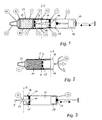
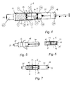
- a filter cartridge 13 either as an integral part of the sampling unit (see the syringe 11 according to FIG Fig. 1 to Fig. 3 ) or as a separate component that is inserted by the user in a sampling unit (see Monovette 12 according to Fig. 4 to Fig. 7 ).
- the filter cartridge 13 has a filter unit 10 with a multi-layer filter, and a plasma collection container 17 (plasma tip) tapered towards the filter unit 10.
- the filter cartridge 13 is after the plasma collection in a plane ⁇ in a plasma applicator 14, which contains the plasma collection container 17 and a filter housing 8, which has the filter unit 10, divisible.
- the in the Fig. 1 to Fig. 3 shown first embodiment variant shows a built-in a syringe 11 filter cartridge 13, in which the filter housing 8, a Luer cone 22 is formed on the needle for removal of whole blood can be plugged.
- a manually displaceable by means of piston rod from a starting position into a dashed end position displaceable piston 18 is arranged, a filter unit 10 and a tapered in the direction of the filter unit 10 tapered plasma collection 17 are arranged as essential parts of the filter cartridge ,
- the piston housing 20 with the displaceable piston 18 serves as a pumping device for generating the necessary negative pressure for the plasma separation.
- a plasma or plasma fraction 40 formed by the multilayer filter consisting of a depth filter 3, a finer pore stop membrane 4 for complete separation of solid blood components. especially red blood cells, RBKs) and a lateral lattice 5, migrates to the tip 9 of the plasma collection container 17.
- the plasma collection container 17 with its tip 9 passes through a seal 15 to the filter unit 10 and is held and sealed at the opposite, open end by a clamping seal 27 having a through-opening to the pumping means (piston member 20).
- a hydrophobic, air-permeable element 16 liquid stop is arranged in the passage opening to the pumping device. This prevents that the plasma obtained can flow out at this opposite the tip 9 passage opening.
- the seal 15 to the filter unit 10 and the clamping seal 27 to the piston housing 20 define in the filter cartridge 13, a compensation volume 21, which is connected via an air-permeable connection, for example, a compensation opening 25 in the clamping gasket 27 or a porous membrane with the pumping device of the syringe 11.
Abstract
Description
Die Erfindung betrifft eine mehrteilige Vorrichtung zur Gewinnung von Plasma aus Vollblut, mit einer Probenentnahmeeinheit zur Aufnahme von Vollblut, einer Filtereinheit aus einem mehrlagigen Schichtfilter zur Abtrennung des Plasmas und einer Pumpeinrichtung, vorzugsweise einer Kolbenpumpe, zur Erzeugung von Unterdruck in der Filtereinheit. Weiters betrifft die Erfindung eine Filterkartusche mit einer mehrlagigen Filtereinheit zur Gewinnung von Plasma aus Vollblut.The invention relates to a multi-part apparatus for obtaining plasma from whole blood, having a sampling unit for receiving whole blood, a filter unit of a multilayer filter for separating the plasma and a pumping device, preferably a piston pump, for generating negative pressure in the filter unit. Furthermore, the invention relates to a filter cartridge with a multi-layer filter unit for obtaining plasma from whole blood.
Neben den vor allem in Labors verwendeten Zentrifugen zur Plasmaabtrennung sind bereits eine Reihe von Vorrichtungen bekannt geworden, bei welchen auch im POC (Point of Care)-Bereich kleinste Plasmamengen durch Abtrennung aus Vollblut mittels Filtern zur Verfügung gestellt werden.In addition to the centrifuges used mainly in laboratories for plasma separation, a number of devices have already become known, in which also in the POC (point of care) area smallest amounts of plasma are made available by separation from whole blood by means of filters.
Im einfachsten Fall kann die Plasmaabtrennung durch einen mehrschichtigen Teststreifen gemäß
Aus der
Aus der
Aufgabe der Erfindung ist es, eine Vorrichtung zur Gewinnung von Plasma aus Vollblut vorzuschlagen, welche einfach und kostengünstig zu handhaben ist, wobei auch bei geringen Probenmengen und/oder hohen Hämatokritwerten für nachfolgende Anwendungsschritte brauchbare Plasmaproben gewonnen und auf einfache Weise der Eingabeeinrichtung eines Analysators zugeführt werden können.The object of the invention is to propose a device for obtaining plasma from whole blood, which is simple and inexpensive to handle, even if small sample quantities and / or high hematocrit values for subsequent application steps usable plasma samples are obtained and fed to the input device of an analyzer in a simple manner can.
Diese Aufgabe wird erfindungsgemäß dadurch gelöst, dass die Filtereinheit und ein in Richtung Filtereinheit spitz zulaufender Plasmasammelbehälter in einer Filterkartusche angeordnet sind, die nach der Plasmagewinnung auftrennbar ist, so dass die Spitze des Plasmasammelbehälters zur Probeneingabe in einen Analysator frei gestellt ist.This object is achieved according to the invention in that the filter unit and a plasma collection container tapering towards the filter unit are arranged in a filter cartridge which can be separated after the plasma collection, so that the tip of the plasma collection container is exposed for sample input into an analyzer.
Bevorzugt kann die Filterkartusche durch Abziehen, Abdrehen oder Abschrauben eines Plasma-Applikators, der den spitz zulaufenden Plasmasammelbehälter enthält, von einem Filtergehäuse, das die Filtereinheit enthält, aufgetrennt werden. Der spitz zulaufende Plasmasammelbehälter kann nach der Plasmagewinnung und dem Abtrennen des Plasma-Applikators direkt mit dessen Spitze am Einfüllmund eines Analysators angedockt und die so gewonnene Plasma probe zur nachfolgenden Analytbestimmung in den Analysator eingesaugt werden.Preferably, the filter cartridge can be separated by removing, twisting or unscrewing a plasma applicator containing the tapered plasma collection container from a filter housing containing the filter unit. The tapered plasma collection container can be docked after the plasma collection and the separation of the plasma applicator directly with the tip of the Einfüllmund an analyzer and sucked the plasma sample thus obtained for subsequent analyte determination in the analyzer.
Bevorzugt durchsetzt der Plasmasammelbehälter mit seiner Spitze eine Dichtung zur Filtereinheit und ist am gegenüberliegenden Ende durch eine Klemmdichtung gehalten, die eine Durchgangsöffnung zur Pumpeinrichtung, beispielsweise einer Kolbenpumpe, aufweist.Preferably, the plasma collection container penetrates with its tip a seal to the filter unit and is held at the opposite end by a clamping seal, which has a passage opening to the pumping device, for example a piston pump.
Die Dichtung zur Filtereinheit und die Klemmdichtung in der Filterkartusche begrenzen ein Totvolumen bzw. Ausgleichsvolumen, das über eine luftdurchlässige Verbindung, beispielsweise eine Ausgleichsöffnung oder eine poröse Membran, mit der Pumpeinrichtung verbunden ist. In vorteilhafter Weise erfolgt dadurch die Beaufschlagung der Filtereinheit nicht unkontrolliert direkt (abhängig von der Handhabung am Kolbenteil der Pumpeinrichtung), sondern langsam und gleichmäßig abfallend, wobei die Druckverhältnisse durch die geometrischen Abmessungen (beispielsweise das Verhältnis des Saugvolumens der Kolbenpumpe zum Ausgleichsvolumen in der Filterkartusche) der einzelnen Bauteile der Separationsvorrichtung und die Kenndaten des Filterelements eingestellt werden können.The seal for the filter unit and the clamping seal in the filter cartridge define a dead volume or compensating volume, which is connected to the pumping device via an air-permeable connection, for example a compensation opening or a porous membrane. Advantageously, this is done by the Actuation of the filter unit is not uncontrolled directly (depending on the handling of the piston part of the pumping device), but slowly and evenly sloping, the pressure conditions by the geometric dimensions (for example, the ratio of the suction volume of the piston pump to the compensating volume in the filter cartridge) of the individual components of the separation device and the characteristics of the filter element can be adjusted.
Gegenstand der Erfindung ist weiters eine Filterkartusche mit einer mehrlagigen Filtereinheit zur Gewinnung von Plasma aus Vollblut, die im Inneren einen spitz zulaufenden Plasmasammelbehälter aufweist, dessen Spitze eine Dichtung zur Filtereinheit durchsetzt, wobei der Plasmasammelbehälter am gegenüberliegenden Ende durch eine Klemmdichtung in der Filterkartusche gehalten ist. Die Filterkartusche kann im Inneren einer Kolbenspritze oder einer Monovette angeordnet, integriert oder in diese eingesetzt sein.The invention further relates to a filter cartridge with a multi-layer filter unit for obtaining plasma from whole blood, which has a tapered plasma collection container inside the tip passes through a seal to the filter unit, wherein the plasma collection container is held at the opposite end by a clamping seal in the filter cartridge. The filter cartridge can be arranged, integrated or inserted in the interior of a syringe or a Monovette.
Die Erfindung wird im Folgenden anhand von Zeichnungen näher erläutert. Es zeigen:
- Fig. 1
- eine erste Ausführungsvariante (Kolbenspritze) der erfindungsgemäßen Vorrichtung zur Gewinnung von Plasma aus Vollblut in einer Schnittdarstellung;
- Fig. 2
- den ersten Teil der Vorrichtung gemäß
Fig. 1 nach der Plasmagewinnung; - Fig. 3
- den zweiten Teil der Vorrichtung gemäß
Fig. 1 nach der Plasmagewinnung; - Fig. 4
- eine zweite Ausführungsvariante (Monovette) der erfindungsgemäßen Vorrichtung zur Gewinnung von Plasma aus Vollblut in einer Schnittdarstellung;
- Fig. 5
- eine Monovette vor der Plasmagewinnung gemäß
Fig. 4 ; - Fig. 6
- eine erfindungsgemäße Filterkartusche zur Gewinnung von Plasma aus Vollblut, einsetzbar in eine Monovette gemäß
Fig. 5 ; sowie - Fig. 7
- die Filterkartusche gemäß
Fig. 6 eingesetzt in die Monovette gemäßFig. 5 in einer Schnittdarstellung.
- Fig. 1
- a first embodiment (plunger syringe) of the inventive apparatus for obtaining plasma from whole blood in a sectional view;
- Fig. 2
- the first part of the device according to
Fig. 1 after plasma extraction; - Fig. 3
- the second part of the device according to
Fig. 1 after plasma extraction; - Fig. 4
- a second embodiment (Monovette) of the inventive apparatus for obtaining plasma from whole blood in a sectional view;
- Fig. 5
- a monovette before plasma extraction according to
Fig. 4 ; - Fig. 6
- a filter cartridge according to the invention for obtaining plasma from whole blood, usable in a Monovette according to
Fig. 5 ; such as - Fig. 7
- the filter cartridge according to
Fig. 6 inserted into the monovette according toFig. 5 in a sectional view.
Allen Ausführungsvarianten gemeinsam ist eine Filterkartusche 13, entweder als integraler Bestandteil der Probenentnahmeeinheit (siehe Kolbenspritze 11 gemäß
Die in den
Bei Betätigung der Vorrichtung wird durch Zurückziehen des Kolbens 18 die Vollblutprobe 41 in die Filtereinheit 10 eingesaugt, wobei sich eine Plasmafront oder Plasmafraktion 40 ausbildet, die durch das mehrlagige Schichtfilter, bestehend aus einem Tiefenfilter 3, einer feinporigeren Stoppmembran 4 zur vollständigen Antrennung fester Blutbestandteile (vor allem roter Blutkörperchen, RBKs) und einem Lateralgitter 5, bis zur Spitze 9 des Plasmasammelbehälters 17 wandert.Upon actuation of the device, retraction of the
Der Plasmasammelbehälter 17 mit seiner Spitze 9 durchsetzt eine Dichtung 15 zur Filtereinheit 10 und wird am gegenüberliegenden, offenen Ende durch eine Klemmdichtung 27 gehalten und abgedichtet, die eine Durchgangsöffnung zur Pumpeinrichtung (Kolbenteil 20) aufweist. In der Durchgangsöffnung zur Pumpeinrichtung ist ein hydrophobes, luftdurchlässiges Element 16 (Liquid-Stop) angeordnet. Dieses verhindert, dass das gewonnene Plasma an dieser der Spitze 9 gegenüberliegenden Durchgangsöffnung ausfließen kann.The
Die Dichtung 15 zur Filtereinheit 10 und die Klemmdichtung 27 zum Kolbengehäuse 20 begrenzen in der Filterkartusche 13 ein Ausgleichsvolumen 21, das über eine luftdurchlässige Verbindung, beispielsweise eine Ausgleichsöffnung 25 in der Klemmdichtung 27 oder eine poröse Membran, mit der Pumpeinrichtung der Kolbenspritze 11 verbunden ist.The
Bei der Plasmagewinnung mit einer ersten Variante der Vorrichtung gemäß
- ●
Entnahme der Kolbenspritze 11mit integrierter Filterkartusche 13 aus einer sterilen Verpackung. - ● Aufstecken einer Nadel auf den Luer-
Konus 22. - ● Einstechen in ein ausgewähltes Blutgefäß.
- ● Ansaugen einer Blutprobe durch Zurückziehen des Kolbens 18 bis zum Anschlag.
- ● Einrasten der Kolbenstange in
eine Raststellung 24.
(Option: Abbrechen der Kolbenstange, um eine Umkehrung der internen Strömungsrichtung bzw. Unterdruckschwankungen und damit verbundene Verunreinigung des gewonnenen Plasmas bei hohem Hämatokrit und/oder geringer Probenmenge zu verhindern.)
- ● Removal of the
syringe 11 withintegrated filter cartridge 13 from a sterile packaging. - ● Attaching a needle to the
Luer cone 22. - ● Insertion into a selected blood vessel.
- ● Aspirate a blood sample by retracting the
piston 18 until it stops. - ● Engaging the piston rod in a
detent position 24.
(Option: Cancel the piston rod to prevent inversion of the internal flow direction or vacuum fluctuations and associated contamination of the recovered plasma at high hematocrit and / or small amount of sample.)
Das Tiefenfilter 3 der Filtereinheit 10 kann z.B. aus bindemittelfreien Glasfasern (typ. FV-2, Fa. Whatman bzw.
- ● Abhängig von Querschnitt der Filtereinheit 10 und vom Hämatokrit bildet sich eine "Plasmafront" oder "Plasmafraktion" 40 aus, die ungehindert durch die
Stoppmembran 4 treten kann. Dabei werden durch dieStoppmembran 4 die restlichen RBKs herausgefiltert, welche durch den Tiefenfilter nicht zurückgehalten wurden. Hierzuweist die Stoppmembran 4 inVergleich zum Tiefenfilter 3 eine deutlich geringere Porengröße auf, beispielsweise Poren mit einem Durchmesser von weniger als 400 nm, bevorzugt mit einem Durchmesser von weniger als 200 nm. Durch dieKombination eines Tiefenfilters 3, welcher aufgrund seiner Porengröße bereits den ganz überwiegenden Teil der Blutzellen zurückhält, aber die Plasmafraktion weitgehend ungestört durchfließen lässt, mit einernachgeschalteten Stoppmembran 4, welche aufgrund ihrer kleineren Porengröße auch die verbleibenden Blutzellen zuverlässig zurückhält, aber aufgrund ihrer begrenzten Porenzahl ohneden vorgeschalteten Tiefenfilter 4 sehr rasch verstopfen würde, kann eine zuverlässige Abtrennung der Blutzellen ohne rasches Verstopfen des Filters erzielt werden, wodurch die Gewinnung eines ausreichenden Volumens einer Plasmaprobe ermöglicht wird. - ● Der eingestellte Unterdruck in
der Filtereinheit 10 von max. 500 mbar, besser 300 mbar, ideal 100 mbar bis 150 mbar, bestimmt mit den geometrischen Verhältnissen (Verhältnis des Ausgleichsvolumens 21zum Saugvolumen 23 des Kolbengehäuses 20) auch die Flussrate und somit die Scherkräfte, die inder Stoppmembran 4der Filtereinheit 10 speziell auf die RBKs einwirken. Ein Zerplatzen (Hämolyse) kann durch eine Optimierung des Ausgleichsvolumens 21 wirksam verhindert werden. - ●
Das Lateralgitter 5der Filtereinheit 10 ermöglicht ein Sammeln und Absaugen des Plasmas nach derStoppmembran 4 in Richtung Plasmasammelbehälter bzw.Plasmasammelbehälter 17, indem ein "Abdichten" durch dieStoppmembran 4 wirksam verhindert wird.Das Lateralgitter 5 bildet durch seine Gitterstruktur einerseits eine nicht durchgängige Auflage für dieStoppmembran 4, so dass Plasma auf der ausgangsseitigen Seite derStoppmembran 4 ausfließen kann. Die Gitterstruktur bewirkt durch die Bildung von Kanälen weiterhin, dass das flächig aus derStoppmembran 4 hindurchtretende Plasma im Bereich des Plasmasammelbehälters 17 zusammenfließen kann.
(Diese Funktion desLateralgitters 5 kann alternativ auch durch entsprechende Strukturierung, beispielsweise durch Prägen, der der Stoppmembran zugewanden Seite der Dichtung 15Bodens der Dichtung 15 bzw. durch deren ausreichende Rauhigkeit sichergestellt werden). - ● Die Plasmagewinnung wird insbesondere auch beendet durch:
- ein
Verschließen der Stoppmembran 4 durch partikuläre Blutbestandteile, oder - insbesondere bei Hämatokritwerten < ca. 40%, durch ein hydrophobes, luftdurchlässiges Element 16 (Liquid-Stopp) am Ende des
Plasmasammelbehälters 17 bzw. in der Durchgangsöffnung der Klemmdichtung 27, welches eine weitere Plasmagewinnung begrenzt, sobald das durch das hydrophobe,luftdurchlässige Element 16 begrenzte Lumen desPlasmasammelbehälters 17 komplett mit dem gewonnenen Plasma gefüllt ist.
- ein
- ● Durch eine optische Kontrolle mittels Markierungen auf
dem Plasmasammelbehälter 17 kann optional überprüft werden, ob die gewünschte Plasmamenge gewonnen werden konnte. - ● Abschrauben oder Abdrehen (siehe
Pfeil 26 inFig. 2 ) des Filtergehäuses 8der Kolbenspritze 11vom Kolbenteil 20 und dadurch Auftrennung der Filterkartusche 13 in einer Ebene ε in einen ersten Teil, der dieFiltereinheit 10 enthält und einen Plasma-Applikator-Teil 14, der denspitz zulaufenden Plasmasammelbehälter 17 enthält, so dass die Spitze 9 desPlasmasammelbehälters 17 frei gestellt ist (Fig. 3 ).
Die inhärent höhere Haftreibung der Klemmdichtung 27 im Vergleich zur Dichtung 15 desPlasmasammelbehälters 17 mit kleinerer Dichtfläche sorgt in der dargestellten Ausführungsform für ein sicheres Abdocken der Spitze 9 desPlasmasammelbehälters 17, bevor durch weiteres Drehen bzw. Abziehendes Gehäuses Belüftungskanäle 19 in der Gehäusewand freigegeben werden, welche einen raschen Druckausgleich zwischen Saugvolumen 23im Kolbengehäuse 20 und Ausgleichsvolumen 21 entweder über die zumindest teilweise poröse Klemmdichtung 27 und/oder dieAusgleichsöffnung 25 ermöglichen.
Ein vorzeitiges Abdocken stellt weiters sicher, dass es beim Abtrennvorgang nicht zu unvorhersehbaren Komplikationen und Verunreinigungen an der Spitze 9 desPlasmasammelbehälters 17 kommen kann.
Der Liquid-Stopp 16 am Ende desPlasmasammelbehälters 17 inder Klemmdichtung 27 verhindert auch ein Fraktionieren der Plasmaprobe im Bereich der Tip-Spitze im Falle eines verzögerten Druckausgleiches zwischen Saugvolumen 23 undAusgleichsvolumen 21.
(Alternativ kann die Spitze 9 desPlasmasammelbehälters 17 auch als Luer-Kegel gestaltet sein). - ● Andocken des mit dem gewonnenen Plasma zumindest teilweise befüllten Plasmasammelbehälters 17 (
samt Kolbengehäuse 20 als Griffstück) an den Einfüllmund eines nicht weiter dargestellten Analysators. - ● Einbringen der Plasmaprobe in den Analysator durch analysatorseitiges Einsaugen aus dem am Einfüllmund des Analysators angedockten Plasmasammelbehälter 17.
Die Ausgleichsöffnung 25 bzw. alternativ die porösen Bereiche der Klemmdichtung 27 erlauben hierbei ein vollständiges Entleeren desPlasmasammelbehälters 17. - ● analytische Bestimmung der Inhaltsstoffe, beispielsweise der Hämoglobinwerte, der erfindungsgemäß gewonnenen Plasmaprobe im Analysator
- Depending on the cross-section of the
filter unit 10 and the hematocrit, a "plasma front" or "plasma fraction" 40 is formed which can pass through thestop membrane 4 unhindered. In this case, the remaining RBKs are filtered out by thestop membrane 4, which were not retained by the depth filter. For this purpose, thestop membrane 4 in comparison to thedepth filter 3 to a significantly smaller pore size, for example, pores with a diameter of less than 400 nm, preferably with a diameter of less than 200 nm. By combining adepth filter 3, which due to its pore size already the retains most of the blood cells, but can flow through the plasma fraction largely undisturbed, with adownstream stop membrane 4, which reliably holds back the remaining blood cells due to their smaller pore size, but would clog very quickly due to their limited pore number without theupstream depth filter 4, a reliable separation of the blood cells without rapid clogging of the filter can be achieved, whereby the recovery of a sufficient volume of a plasma sample is made possible. - ● The set negative pressure in the
filter unit 10 of max. 500 mbar, better 300 mbar, ideally 100 mbar to 150 mbar, determined by the geometric conditions (ratio of the compensatingvolume 21 to thesuction volume 23 of the piston housing 20) also the flow rate and thus the shear forces in thestop membrane 4 of thefilter unit 10 specifically on the RBKs interact. A burst (hemolysis) can be effectively prevented by optimizing thecompensation volume 21. - The
lateral lattice 5 of thefilter unit 10 enables collection and suction of the plasma after thestop membrane 4 in the direction of the plasma collection container orplasma collection container 17 by effectively preventing "sealing" by thestop membrane 4. By virtue of its lattice structure, thelateral grid 5 on the one hand forms a non-continuous support for thestop membrane 4, so that plasma can flow out on the output side of thestop membrane 4. As a result of the formation of channels, the lattice structure furthermore causes the plasma, which passes flatly from thestop membrane 4, to flow together in the region of theplasma collection container 17.
(Alternatively, this function of thelateral grid 5 can also be ensured by appropriate structuring, for example by embossing, the side of theseal 15 bottom of theseal 15 or by its sufficient roughness facing the stop membrane). - ● The plasma extraction is also terminated by:
- closing the
stop membrane 4 by particulate blood components, or - in particular at hematocrit values <about 40%, by a hydrophobic, air-permeable element 16 (liquid stop) at the end of the
plasma collection container 17 or in the passage opening of the clampinggasket 27, which limits further plasma recovery as soon as passing through the hydrophobic, air-permeable element 16 limited lumen of theplasma collection container 17 is completely filled with the recovered plasma.
- closing the
- ● By means of visual inspection by means of markings on the
plasma collection container 17, it is optionally possible to check whether the desired amount of plasma could be obtained. - ● Unscrew or twist off (see
arrow 26 inFig. 2 ) of thefilter housing 8 of theplunger syringe 11 from thepiston part 20 and thereby separating thefilter cartridge 13 in a plane ε in a first part containing thefilter unit 10 and aplasma applicator part 14 containing the taperedplasma collection container 17 so that the Tip 9 of theplasma collection container 17 is exposed (Fig. 3 ).
The inherently higher static friction of the clampingseal 27 compared to theseal 15 of theplasma collection container 17 with a smaller sealing surface ensures in the illustrated embodiment for a safe undocking of the tip 9 of theplasma collection container 17 before ventingchannels 19 in the housing wall are released by further rotation or removal of the housing, which allow rapid pressure equalization between thesuction volume 23 in thepiston housing 20 and compensatingvolume 21 either via the at least partiallyporous clamping gasket 27 and / or thecompensation opening 25 ,
Premature doffing further ensures that there are no unpredictable complications and contaminants at the tip 9 of theplasma collection container 17 during the separation process.
Theliquid stop 16 at the end of theplasma collection container 17 in the clampinggasket 27 also prevents fractionation of the plasma sample in the region of the tip tip in the event of a delayed pressure equalization between thesuction volume 23 andequalization volume 21.
(Alternatively, the tip 9 of theplasma collection container 17 may also be designed as a luer cone). - ● Docking of the collected plasma at least partially filled plasma collection container 17 (including the
piston housing 20 as a handle) to the filling mouth of an analyzer, not shown. - ● Introduction of the plasma sample into the analyzer by sucking in the analyzer from the
plasma collecting container 17 docked at the filling mouth of the analyzer. The compensatingopening 25 or, alternatively, the porous regions of the clampinggasket 27 permit complete emptying of theplasma collecting container 17. - ● analytical determination of the ingredients, for example the hemoglobin values, of the plasma sample obtained according to the invention in the analyzer
Bei der Plasmagewinnung mit einer zweiten Variante der Vorrichtung gemäß
- ●
Entnahme einer Monovette 12 gemäßFig. 5 aus einer sterilen Verpackung. - ● Abschrauben der Adapterkappe 28
mit der Durchstechmembran 29vom Kolbengehäuse 20. - ●
Einbau der Filterkartusche 13zwischen Adapterkappe 28 und Kolbengehäuse 20 gemäßFig. 4 - ● Herstellen eines Unterdrucks in
der Monovette 12 durch:- Zurückziehen des Kolbens 18 bis zum Anschlag
- Einrasten der Kolbenstange in eine strichliert dargestellte Raststellung 24
- (Option: Abbrechen der Kolbenstange, um eine Umkehrung der internen Strömungsrichtung zu verhindern)
- ●
Andocken der Durchstechmembran 29 der Adapterkappe 28 an eine Punktiernadel, z.B. Butterfly. - ● Einsaugen der Blutprobe durch den in
der Monovette 12 herrschenden Unterdruck.
- ● Removing a
Monovette 12 according toFig. 5 from a sterile packaging. - ● Unscrew the
adapter cap 28 with the piercingmembrane 29 from thepiston housing 20. - ● Installation of
filter cartridge 13 betweenadapter cap 28 andpiston housing 20 according to FIGFig. 4 - ● creating a vacuum in the
Monovette 12 by:- Retract the
piston 18 until it stops - Engaging the piston rod in a
detent position 24 shown in dashed lines - (Option: Cancel the piston rod to prevent inversion of the internal flow direction)
- Retract the
- ● Docking the piercing
membrane 29 of theadapter cap 28 to a puncturing needle, eg butterfly. - ● Aspiration of the blood sample by the prevailing in the
Monovette 12 negative pressure.
Das Tiefenfilter 3 der Filtereinheit 10 kann z.B. aus bindemittelfreien Glasfasern (typ. FV-2, Fa. Whatman bzw.
- ● Abhängig von Querschnitt der Filtereinheit 10 und vom Hämatokrit bildet sich eine "Plasmafront" oder "Plasmafraktion" 40 aus, die ungehindert durch die
Stoppmembran 4 treten kann. Dabei werden die restlichen RBKs herausgefiltert (Fig. 4 ), welche durch den Tiefenfilter nicht zurückgehalten wurden. Hierzuweist die Stoppmembran 4 inVergleich zum Tiefenfilter 3 eine deutlich geringere Porengröße auf, beispielsweise Poren mit einem Durchmesser von weniger als 400 nm, bevorzugt mit einem Durchmesser von weniger als 200 nm. Durch dieKombination eines Tiefenfilters 3, welcher aufgrund seiner Porengröße bereits den ganz überwiegenden Teil der Blutzellen zurückhält, aber die Plasmafraktion weitgehend ungestört durchfließen lässt, mit einernachgeschalteten Stoppmembran 4, welche aufgrund ihrer kleineren Porengröße auch die verbleibenden Blutzellen zuverlässig zurückhält, aber aufgrund ihrer begrenzten Porenzahl ohneden vorgeschalteten Tiefenfilter 4 sehr rasch verstopfen würde, kann eine zuverlässige Abtrennung der Blutzellen ohne rasches Verstopfen des Filters erzielt werden, wodurch die Gewinnung eines ausreichenden Volumens einer Plasmaprobe ermöglicht wird. - ● Der eingestellte Unterdruck in
der Filtereinheit 10 von max. 500 mbar, besser 300 mbar, ideal 100 mbar bis 150 mbar, bestimmt mit den geometrischen Verhältnissen (Verhältnis des Ausgleichsvolumens 21zum Saugvolumen 23 des Kolbengehäuses 20) auch die Flussrate und somit die Scherkräfte, die inder Stoppmembran 4der Filtereinheit 10 speziell auf die RBKs einwirken. Ein Zerplatzen (Hämolyse) kann durch Optimierung des Ausgleichsvolumens 21 wirksam verhindert werden. - ●
Das Lateralgitter 5der Filtereinheit 10 ermöglicht ein Sammeln und Absaugen des Plasmas nach derStoppmembran 4 inRichtung Plasmasammelbehälter 17, indem ein "Abdichten" durch dieStoppmembran 4 wirksam verhindert wird. (siehe auch Variante Kolbenspritze)
(Diese Funktion desLateralgitters 5 kann alternativ auch durch entsprechende Strukturierung, beispielsweise durch Prägen, der der Stoppmembran zugewanden Seite der Dichtung 15Bodens der Dichtung 15 bzw. durch deren ausreichende Rauhigkeit sichergestellt werden). - ● Die Plasmagewinnung wird insbesondere auch beendet durch:
- ein
Verschließen der Stoppmembran 4 durch partikuläre Blutbestandteile, oder - insbesondere bei Hämatokritwerten < ca. 40%, durch ein hydrophobes, luftdurchlässiges Element 16 (Liquid-Stopp) am Ende des
Plasmasammelbehälters 17 bzw. in der Durchgangsöffnung der Klemmdichtung 27, welches eine weitere Plasmagewinnung begrenzt, sobald das durch das hydrophobe,luftdurchlässige Element 16 begrenzte Lumen desPlasmasammelbehälters 17 komplett mit dem gewonnenen Plasma gefüllt ist.
- ein
- ● Durch eine optische Kontrolle mittels Markierungen auf
dem Plasmasammelbehälter 17, kann auch hier optional überprüft werden, ob die gewünschte Plasmamenge gewonnen werden konnte. - ● Abschrauben oder Abdrehen des vorderen Teils der Monovette 12
vom Kolbenteil 20 und dadurch Auftrennung der dazwischen eingebrachten Filterkartusche 13 inein Filtergehäuse 8, das die Filtereinheit 10 enthält und einen Plasma-Applikator 14, der denspitz zulaufenden Plasmasammelbehälter 17 enthält, in einer Ebene ε, so dass die Spitze 9 desPlasmasammelbehälters 17 frei gestellt ist (Fig. 7 ). Zur besseren Handhabung bleibt der Plasma-Applikator 14mit dem Kolbengehäuse 20 verbunden. Nach der Abtrennung entspricht die Vorrichtung jener inFig. 3 .
- Depending on the cross-section of the
filter unit 10 and the hematocrit, a "plasma front" or "plasma fraction" 40 is formed which can pass through thestop membrane 4 unhindered. The remaining RBKs are filtered out (Fig. 4 ), which were not retained by the depth filter. For this purpose, thestop membrane 4 in comparison to thedepth filter 3 to a significantly smaller pore size, for example, pores with a diameter of less than 400 nm, preferably with a diameter of less than 200 nm. By combining adepth filter 3, which due to its pore size already the retains most of the blood cells, but can flow through the plasma fraction largely undisturbed, with adownstream stop membrane 4, which reliably holds back the remaining blood cells due to their smaller pore size, but would clog very quickly due to their limited pore number without theupstream depth filter 4, a reliable separation of the blood cells without rapid clogging of the filter can be achieved, whereby the recovery of a sufficient volume of a plasma sample is made possible. - ● The set negative pressure in the
filter unit 10 of max. 500 mbar, better 300 mbar, ideally 100 mbar to 150 mbar, determined with the geometrical conditions (ratio of thecompensation volume 21 to thesuction volume 23 of the piston housing 20) also the flow rate and thus the shear forces in thestop membrane 4 of thefilter unit 10 specifically on the RBKs interact. A burst (hemolysis) can be effectively prevented by optimizing thecompensation volume 21. - The
lateral lattice 5 of thefilter unit 10 allows collection and suction of the plasma after thestop membrane 4 in the direction of theplasma collection container 17, by a "sealing" by thestop membrane 4 is effectively prevented. (see also variant syringe syringe)
(Alternatively, this function of thelateral grid 5 can also be ensured by appropriate structuring, for example by embossing, the side of theseal 15 bottom of theseal 15 or by its sufficient roughness facing the stop membrane). - ● The plasma extraction is also terminated by:
- closing the
stop membrane 4 by particulate blood components, or - in particular at hematocrit values <about 40%, by a hydrophobic, air-permeable element 16 (liquid stop) at the end of the
plasma collection container 17 or in the passage opening of the clampinggasket 27, which limits further plasma recovery as soon as passing through the hydrophobic, air-permeable element 16 limited lumen of theplasma collection container 17 is completely filled with the recovered plasma.
- closing the
- ● By means of an optical control by means of markings on the
plasma collection container 17, it is also optionally possible to check whether the desired amount of plasma could be obtained. - ● unscrewing or twisting off the front part of the monovette 12 from the
piston part 20 and thereby separating the interposedfilter cartridge 13 in afilter housing 8 containing thefilter unit 10 and aplasma applicator 14 containing the taperedplasma collection container 17 in a plane ε such that the tip 9 of theplasma collection container 17 is exposed (Fig. 7 ). For better handling, theplasma applicator 14 remains connected to thepiston housing 20. After separation, the device corresponds to that inFig. 3 ,
Die weiteren Schritte entsprechen jenen bei der oben beschriebenen ersten Ausführungsvariante der erfindungsgemäßen Vorrichtung.The further steps correspond to those in the first embodiment of the device according to the invention described above.
Claims (12)
Priority Applications (7)
| Application Number | Priority Date | Filing Date | Title |
|---|---|---|---|
| EP12179900.1A EP2695655A1 (en) | 2012-08-09 | 2012-08-09 | Multi-part device for extracting plasma from blood |
| EP13745674.5A EP2882511A1 (en) | 2012-08-09 | 2013-08-07 | Multi-part device for extracting plasma from blood |
| CN201380042324.5A CN104519976B (en) | 2012-08-09 | 2013-08-07 | For extracting the multi-part device of blood plasma from blood |
| JP2015525876A JP2015527582A (en) | 2012-08-09 | 2013-08-07 | Multi-part component device for extracting plasma from blood |
| PCT/EP2013/066539 WO2014023761A1 (en) | 2012-08-09 | 2013-08-07 | Multi-part device for extracting plasma from blood |
| US14/615,743 US9283313B2 (en) | 2012-08-09 | 2015-02-06 | Device and filter cartridge for separating plasma from whole blood |
| HK15106907.2A HK1206301A1 (en) | 2012-08-09 | 2015-07-21 | Multi-part device for extracting plasma from blood |
Applications Claiming Priority (1)
| Application Number | Priority Date | Filing Date | Title |
|---|---|---|---|
| EP12179900.1A EP2695655A1 (en) | 2012-08-09 | 2012-08-09 | Multi-part device for extracting plasma from blood |
Publications (1)
| Publication Number | Publication Date |
|---|---|
| EP2695655A1 true EP2695655A1 (en) | 2014-02-12 |
Family
ID=46851288
Family Applications (2)
| Application Number | Title | Priority Date | Filing Date |
|---|---|---|---|
| EP12179900.1A Withdrawn EP2695655A1 (en) | 2012-08-09 | 2012-08-09 | Multi-part device for extracting plasma from blood |
| EP13745674.5A Withdrawn EP2882511A1 (en) | 2012-08-09 | 2013-08-07 | Multi-part device for extracting plasma from blood |
Family Applications After (1)
| Application Number | Title | Priority Date | Filing Date |
|---|---|---|---|
| EP13745674.5A Withdrawn EP2882511A1 (en) | 2012-08-09 | 2013-08-07 | Multi-part device for extracting plasma from blood |
Country Status (6)
| Country | Link |
|---|---|
| US (1) | US9283313B2 (en) |
| EP (2) | EP2695655A1 (en) |
| JP (1) | JP2015527582A (en) |
| CN (1) | CN104519976B (en) |
| HK (1) | HK1206301A1 (en) |
| WO (1) | WO2014023761A1 (en) |
Families Citing this family (18)
| Publication number | Priority date | Publication date | Assignee | Title |
|---|---|---|---|---|
| JP2016533497A (en) | 2013-07-09 | 2016-10-27 | エスアールアイ インターナショナルSRI International | Biomarker panel and microplasma filter for dose assessment of radiation injury |
| WO2016073415A2 (en) * | 2014-11-04 | 2016-05-12 | Wainamics, Inc. | Microscale plasma separator |
| WO2017027433A1 (en) | 2015-08-07 | 2017-02-16 | Schlumberger Technology Corporation | Method of performing integrated fracture and reservoir operations for multiple wellbores at a wellsite |
| US10920538B2 (en) | 2015-08-07 | 2021-02-16 | Schlumberger Technology Corporation | Method integrating fracture and reservoir operations into geomechanical operations of a wellsite |
| US10794154B2 (en) | 2015-08-07 | 2020-10-06 | Schlumberger Technology Corporation | Method of performing complex fracture operations at a wellsite having ledged fractures |
| WO2017027068A1 (en) | 2015-08-07 | 2017-02-16 | Schlumberger Technology Corporation | Well management on cloud computing system |
| JP2018536142A (en) * | 2015-09-01 | 2018-12-06 | ベクトン・ディキンソン・アンド・カンパニーBecton, Dickinson And Company | Depth filtration device for separating sample phases |
| EP3165921A1 (en) * | 2015-11-05 | 2017-05-10 | Dominik Olbrzymek | A kit for centrifugal separation of biological fluid components and a method for centrifugal separation of biological fluid components |
| CN105445083B (en) * | 2015-12-21 | 2018-09-11 | 丹娜(天津)生物科技有限公司 | Exempt to centrifuge whole blood processing module |
| CN115254210A (en) | 2016-11-14 | 2022-11-01 | 浩康生物系统公司 | Method and apparatus for sorting target particles |
| CN110891623B (en) * | 2017-07-17 | 2022-08-26 | 波士顿科学国际有限公司 | Cryotherapy delivery device |
| CN109806657A (en) * | 2017-11-20 | 2019-05-28 | 李泉 | A kind of blood plasma extraction element |
| CN108577896A (en) * | 2018-03-20 | 2018-09-28 | 四川大学华西第二医院 | Specimen collecting bottle |
| EP4001916A1 (en) * | 2018-06-07 | 2022-05-25 | Becton, Dickinson and Company | Biological fluid separation device |
| DE102020203295B4 (en) * | 2019-03-15 | 2023-01-12 | Seigniory Chemical Products Ltd. - Produits Chimiques Seigneurie Ltée | SYSTEM AND PROCEDURE FOR FILTERING SAMPLES FROM VESSELS |
| US10518260B1 (en) | 2019-05-01 | 2019-12-31 | Nano Discovery, Inc. | Device for separation of plasma or serum from blood cells and methods of using the device |
| US11439768B2 (en) * | 2019-07-17 | 2022-09-13 | Wagner Florexil | Compartmentalized syringe for combined medicine and flush solution |
| CN111141569B (en) * | 2020-01-22 | 2020-12-29 | 兰州大学 | Hydrops class pathological analysis sediment layer extraction element |
Citations (8)
| Publication number | Priority date | Publication date | Assignee | Title |
|---|---|---|---|---|
| US4046145A (en) * | 1976-06-29 | 1977-09-06 | American Hospital Supply Corporation | Syringe connector |
| EP0239002A1 (en) | 1986-03-27 | 1987-09-30 | Roche Diagnostics GmbH | Test support and method for the determination of coagulation parameters |
| DE4015589A1 (en) | 1990-05-15 | 1991-11-21 | Boehringer Mannheim Gmbh | DEVICE AND THE USE THEREOF FOR SEPARATING PLASMA FROM WHOLE BLOOD |
| EP0550950A2 (en) | 1992-01-10 | 1993-07-14 | Sanwa Kagaku Kenkyusho Co., Ltd. | Process and device for separating blood serum and plasma |
| US5336412A (en) * | 1989-01-03 | 1994-08-09 | Stratagene | Push column chromatography method |
| WO1996024425A1 (en) | 1995-02-09 | 1996-08-15 | First Medical, Inc. | Peristaltic system and method for plasma separation |
| US6761855B1 (en) * | 2001-11-05 | 2004-07-13 | Biosearch Technologies, Inc. | Column for solid phase processing |
| EP1469068A1 (en) * | 2003-03-28 | 2004-10-20 | Fuji Photo Film Co. Ltd. | Apparatus for separating and purifying nucleid acid and method for separating and purifying nucleid acid |
Family Cites Families (26)
| Publication number | Priority date | Publication date | Assignee | Title |
|---|---|---|---|---|
| US3814079A (en) * | 1972-04-28 | 1974-06-04 | Upjohn Co | Liquid collecting and filtering device |
| FR2274918A1 (en) * | 1974-03-30 | 1976-01-09 | Sarstedt Kunststoff | FILTERING DEVICE FOR SEPARATION OF BLOOD FRACTIONS |
| DE2415618C3 (en) * | 1974-03-30 | 1978-06-22 | Walter Sarstedt Kunststoff-Spritzgusswerk, 5223 Nuembrecht | Filter device for separating blood fractions |
| US4131549A (en) | 1977-05-16 | 1978-12-26 | Ferrara Louis T | Serum separation device |
| US4921618A (en) | 1987-07-01 | 1990-05-01 | Basf Corporation | Inverted separation and transfer device, and process for using same |
| US4990253A (en) | 1988-01-25 | 1991-02-05 | Abbott Laboratories | Fluid sample filtration device |
| DE3913197A1 (en) * | 1989-04-21 | 1990-10-25 | Sarstedt Walter Geraete | BLOOD COLLECTION DEVICE |
| JPH0593721A (en) * | 1990-12-03 | 1993-04-16 | Sanwa Kagaku Kenkyusho Co Ltd | Serum/plasma separating apparatus |
| US5234608A (en) | 1990-12-11 | 1993-08-10 | Baxter International Inc. | Systems and methods for processing cellular rich suspensions |
| US5139685A (en) * | 1991-03-26 | 1992-08-18 | Gds Technology, Inc. | Blood separation filter assembly and method |
| US5672481A (en) | 1991-10-23 | 1997-09-30 | Cellpro, Incorporated | Apparatus and method for particle separation in a closed field |
| US5578459A (en) * | 1993-11-24 | 1996-11-26 | Abbott Laboratories | Method and apparatus for collecting a cell sample from a liquid specimen |
| GB9426251D0 (en) * | 1994-12-24 | 1995-02-22 | Fsm Technologies Ltd | Device |
| US5637087A (en) * | 1995-03-22 | 1997-06-10 | Abbott Laboratories | Prefilled, two-constituent syringe |
| JPH09196911A (en) * | 1996-01-19 | 1997-07-31 | Fuji Photo Film Co Ltd | Blood filter unit |
| US6117394A (en) * | 1996-04-10 | 2000-09-12 | Smith; James C. | Membrane filtered pipette tip |
| US6669905B1 (en) * | 1998-05-21 | 2003-12-30 | Baxter International Inc. | Systems and methods for collecting plasma that is free or virtually free of cellular blood species |
| CN1420796A (en) * | 2000-03-31 | 2003-05-28 | 巴克斯特国际公司 | Systems and methods for collecting leukocyte-reduced blood components, including plasma that is free or virtually free of cellular blood species |
| US6817256B2 (en) * | 2001-02-27 | 2004-11-16 | Alfa Wassermann, Inc. | Pipette sampling system |
| US6869405B2 (en) * | 2001-03-30 | 2005-03-22 | Becton, Dickinson And Company | Blunt cannula and filter assembly and method of use with point-of-care testing cartridge |
| DE102004056655B4 (en) * | 2004-11-23 | 2007-03-29 | Sarstedt Ag & Co. | Sample tubes for receiving body fluid, in particular blood |
| JP2007003479A (en) * | 2005-06-27 | 2007-01-11 | Sekisui Chem Co Ltd | Blood separation device |
| US20100093551A1 (en) * | 2008-10-09 | 2010-04-15 | Decision Biomarkers, Inc. | Liquid Transfer and Filter System |
| EP2264453B1 (en) * | 2009-06-17 | 2013-04-03 | Leukocare Ag | Method for filtering blood |
| DK2477742T3 (en) | 2009-09-17 | 2013-08-05 | Hoffmann La Roche | Sample supply apparatus for supplying liquid samples (apparatus for gripping lumps) |
| EP2637788A1 (en) | 2010-11-10 | 2013-09-18 | Boehringer Ingelheim Microparts GmbH | Device for filtering blood |
-
2012
- 2012-08-09 EP EP12179900.1A patent/EP2695655A1/en not_active Withdrawn
-
2013
- 2013-08-07 WO PCT/EP2013/066539 patent/WO2014023761A1/en active Application Filing
- 2013-08-07 CN CN201380042324.5A patent/CN104519976B/en not_active Expired - Fee Related
- 2013-08-07 JP JP2015525876A patent/JP2015527582A/en active Pending
- 2013-08-07 EP EP13745674.5A patent/EP2882511A1/en not_active Withdrawn
-
2015
- 2015-02-06 US US14/615,743 patent/US9283313B2/en not_active Expired - Fee Related
- 2015-07-21 HK HK15106907.2A patent/HK1206301A1/en not_active IP Right Cessation
Patent Citations (8)
| Publication number | Priority date | Publication date | Assignee | Title |
|---|---|---|---|---|
| US4046145A (en) * | 1976-06-29 | 1977-09-06 | American Hospital Supply Corporation | Syringe connector |
| EP0239002A1 (en) | 1986-03-27 | 1987-09-30 | Roche Diagnostics GmbH | Test support and method for the determination of coagulation parameters |
| US5336412A (en) * | 1989-01-03 | 1994-08-09 | Stratagene | Push column chromatography method |
| DE4015589A1 (en) | 1990-05-15 | 1991-11-21 | Boehringer Mannheim Gmbh | DEVICE AND THE USE THEREOF FOR SEPARATING PLASMA FROM WHOLE BLOOD |
| EP0550950A2 (en) | 1992-01-10 | 1993-07-14 | Sanwa Kagaku Kenkyusho Co., Ltd. | Process and device for separating blood serum and plasma |
| WO1996024425A1 (en) | 1995-02-09 | 1996-08-15 | First Medical, Inc. | Peristaltic system and method for plasma separation |
| US6761855B1 (en) * | 2001-11-05 | 2004-07-13 | Biosearch Technologies, Inc. | Column for solid phase processing |
| EP1469068A1 (en) * | 2003-03-28 | 2004-10-20 | Fuji Photo Film Co. Ltd. | Apparatus for separating and purifying nucleid acid and method for separating and purifying nucleid acid |
Also Published As
| Publication number | Publication date |
|---|---|
| CN104519976A (en) | 2015-04-15 |
| EP2882511A1 (en) | 2015-06-17 |
| WO2014023761A1 (en) | 2014-02-13 |
| US9283313B2 (en) | 2016-03-15 |
| HK1206301A1 (en) | 2016-01-08 |
| JP2015527582A (en) | 2015-09-17 |
| CN104519976B (en) | 2017-03-01 |
| US20150151035A1 (en) | 2015-06-04 |
Similar Documents
| Publication | Publication Date | Title |
|---|---|---|
| EP2695655A1 (en) | Multi-part device for extracting plasma from blood | |
| EP2695652A1 (en) | System for separating plasma from blood | |
| DE60011685T2 (en) | Adsorbent cartridge for extraction with a solid phase | |
| DE4409842C2 (en) | Procedure for obtaining a blood sample from the umbilical cord of a newborn child | |
| EP2695656A1 (en) | Method and separation device for separating a filtrate from a sample liquid | |
| EP2477742B1 (en) | Sample input device for inputting liquid samples (clot catcher) | |
| EP1315553B1 (en) | Device and method for separating undissolved constituents out of biological fluids | |
| EP0017728A2 (en) | Blood letting instrument with blood sampling cannula and method of evacuating the cannula | |
| DE2525713A1 (en) | DEVICE FOR TRANSFERRING BLOOD OR SIMILAR LIQUID INTO A PIPETTE | |
| EP2398591A1 (en) | Method and device for providing blood constituents | |
| DE202017007384U1 (en) | Combined centrifugal device | |
| DE2415618C3 (en) | Filter device for separating blood fractions | |
| DE102013215565A1 (en) | Device for introducing a liquid sample into a microfluidic system | |
| DE69907678T2 (en) | METHOD AND DEVICE FOR TAKING LIQUID SAMPLES FROM A SEALED VESSEL | |
| EP0114281A2 (en) | Device for producing cellular material from body liquids | |
| DE19820178C2 (en) | Device for enriching particles in body fluid | |
| DE19647674C1 (en) | Method for automatically pushing a filter into a blood container | |
| DE102013000922A1 (en) | Autonomous samplers for biological fluids in system, has sampling body, which is formed hollow-cylindrical and is combined in region of its inner surface with intermediate piece | |
| DE10340012A1 (en) | Device for gas or liquid separation from microfluidic flow systems | |
| EP3359961B1 (en) | Method for separating the phases of a liquid mixture and subsequently separating a liquid supernatant and phase separator for the method | |
| WO2001084113A1 (en) | Method and device for filtering a liquid sample, especially for obtaining medical preparations | |
| DE102016123658B4 (en) | Filtration device and method for the enrichment of targets and the subsequent release of biogenic agents | |
| WO2000020092A2 (en) | Pipette-type filtering device | |
| WO2020099475A2 (en) | Device and method for obtaining a cell-free sample fraction | |
| DE102019215029A1 (en) | Filter sequence, syringe attachment and method for separating particles from a body fluid |
Legal Events
| Date | Code | Title | Description |
|---|---|---|---|
| AK | Designated contracting states |
Kind code of ref document: A1 Designated state(s): AL AT BE BG CH CY CZ DE DK EE ES FI FR GB GR HR HU IE IS IT LI LT LU LV MC MK MT NL NO PL PT RO RS SE SI SK SM TR |
|
| AX | Request for extension of the european patent |
Extension state: BA ME |
|
| PUAI | Public reference made under article 153(3) epc to a published international application that has entered the european phase |
Free format text: ORIGINAL CODE: 0009012 |
|
| STAA | Information on the status of an ep patent application or granted ep patent |
Free format text: STATUS: THE APPLICATION IS DEEMED TO BE WITHDRAWN |
|
| 18D | Application deemed to be withdrawn |
Effective date: 20140813 |