EP2682999A2 - Battery pack having excellent structural reliability - Google Patents
Battery pack having excellent structural reliability Download PDFInfo
- Publication number
- EP2682999A2 EP2682999A2 EP12785676.3A EP12785676A EP2682999A2 EP 2682999 A2 EP2682999 A2 EP 2682999A2 EP 12785676 A EP12785676 A EP 12785676A EP 2682999 A2 EP2682999 A2 EP 2682999A2
- Authority
- EP
- European Patent Office
- Prior art keywords
- battery
- battery pack
- upper mounting
- members
- pack according
- Prior art date
- Legal status (The legal status is an assumption and is not a legal conclusion. Google has not performed a legal analysis and makes no representation as to the accuracy of the status listed.)
- Granted
Links
- 230000003014 reinforcing effect Effects 0.000 claims description 7
- 230000008878 coupling Effects 0.000 claims description 5
- 238000010168 coupling process Methods 0.000 claims description 5
- 238000005859 coupling reaction Methods 0.000 claims description 5
- 238000001816 cooling Methods 0.000 claims description 3
- 238000003466 welding Methods 0.000 claims description 2
- 238000005452 bending Methods 0.000 description 2
- 238000010276 construction Methods 0.000 description 2
- 238000009434 installation Methods 0.000 description 2
- 239000010410 layer Substances 0.000 description 2
- 239000002952 polymeric resin Substances 0.000 description 2
- 229920003002 synthetic resin Polymers 0.000 description 2
- HBBGRARXTFLTSG-UHFFFAOYSA-N Lithium ion Chemical compound [Li+] HBBGRARXTFLTSG-UHFFFAOYSA-N 0.000 description 1
- 238000003915 air pollution Methods 0.000 description 1
- 230000004888 barrier function Effects 0.000 description 1
- 230000000903 blocking effect Effects 0.000 description 1
- 239000011247 coating layer Substances 0.000 description 1
- 238000001514 detection method Methods 0.000 description 1
- 230000006866 deterioration Effects 0.000 description 1
- 239000003792 electrolyte Substances 0.000 description 1
- 238000005516 engineering process Methods 0.000 description 1
- 230000001747 exhibiting effect Effects 0.000 description 1
- 239000002803 fossil fuel Substances 0.000 description 1
- 229910001416 lithium ion Inorganic materials 0.000 description 1
- 229910052987 metal hydride Inorganic materials 0.000 description 1
- 239000007769 metal material Substances 0.000 description 1
- 238000000034 method Methods 0.000 description 1
- 238000012986 modification Methods 0.000 description 1
- 230000004048 modification Effects 0.000 description 1
- 239000000565 sealant Substances 0.000 description 1
- 230000035939 shock Effects 0.000 description 1
- 230000008961 swelling Effects 0.000 description 1
Images


Classifications
-
- B—PERFORMING OPERATIONS; TRANSPORTING
- B60—VEHICLES IN GENERAL
- B60K—ARRANGEMENT OR MOUNTING OF PROPULSION UNITS OR OF TRANSMISSIONS IN VEHICLES; ARRANGEMENT OR MOUNTING OF PLURAL DIVERSE PRIME-MOVERS IN VEHICLES; AUXILIARY DRIVES FOR VEHICLES; INSTRUMENTATION OR DASHBOARDS FOR VEHICLES; ARRANGEMENTS IN CONNECTION WITH COOLING, AIR INTAKE, GAS EXHAUST OR FUEL SUPPLY OF PROPULSION UNITS IN VEHICLES
- B60K1/00—Arrangement or mounting of electrical propulsion units
- B60K1/04—Arrangement or mounting of electrical propulsion units of the electric storage means for propulsion
-
- B—PERFORMING OPERATIONS; TRANSPORTING
- B60—VEHICLES IN GENERAL
- B60L—PROPULSION OF ELECTRICALLY-PROPELLED VEHICLES; SUPPLYING ELECTRIC POWER FOR AUXILIARY EQUIPMENT OF ELECTRICALLY-PROPELLED VEHICLES; ELECTRODYNAMIC BRAKE SYSTEMS FOR VEHICLES IN GENERAL; MAGNETIC SUSPENSION OR LEVITATION FOR VEHICLES; MONITORING OPERATING VARIABLES OF ELECTRICALLY-PROPELLED VEHICLES; ELECTRIC SAFETY DEVICES FOR ELECTRICALLY-PROPELLED VEHICLES
- B60L50/00—Electric propulsion with power supplied within the vehicle
- B60L50/50—Electric propulsion with power supplied within the vehicle using propulsion power supplied by batteries or fuel cells
- B60L50/60—Electric propulsion with power supplied within the vehicle using propulsion power supplied by batteries or fuel cells using power supplied by batteries
- B60L50/66—Arrangements of batteries
-
- H—ELECTRICITY
- H01—ELECTRIC ELEMENTS
- H01M—PROCESSES OR MEANS, e.g. BATTERIES, FOR THE DIRECT CONVERSION OF CHEMICAL ENERGY INTO ELECTRICAL ENERGY
- H01M50/00—Constructional details or processes of manufacture of the non-active parts of electrochemical cells other than fuel cells, e.g. hybrid cells
- H01M50/10—Primary casings, jackets or wrappings of a single cell or a single battery
- H01M50/102—Primary casings, jackets or wrappings of a single cell or a single battery characterised by their shape or physical structure
- H01M50/103—Primary casings, jackets or wrappings of a single cell or a single battery characterised by their shape or physical structure prismatic or rectangular
-
- H—ELECTRICITY
- H01—ELECTRIC ELEMENTS
- H01M—PROCESSES OR MEANS, e.g. BATTERIES, FOR THE DIRECT CONVERSION OF CHEMICAL ENERGY INTO ELECTRICAL ENERGY
- H01M50/00—Constructional details or processes of manufacture of the non-active parts of electrochemical cells other than fuel cells, e.g. hybrid cells
- H01M50/10—Primary casings, jackets or wrappings of a single cell or a single battery
- H01M50/116—Primary casings, jackets or wrappings of a single cell or a single battery characterised by the material
- H01M50/124—Primary casings, jackets or wrappings of a single cell or a single battery characterised by the material having a layered structure
-
- H—ELECTRICITY
- H01—ELECTRIC ELEMENTS
- H01M—PROCESSES OR MEANS, e.g. BATTERIES, FOR THE DIRECT CONVERSION OF CHEMICAL ENERGY INTO ELECTRICAL ENERGY
- H01M50/00—Constructional details or processes of manufacture of the non-active parts of electrochemical cells other than fuel cells, e.g. hybrid cells
- H01M50/20—Mountings; Secondary casings or frames; Racks, modules or packs; Suspension devices; Shock absorbers; Transport or carrying devices; Holders
- H01M50/249—Mountings; Secondary casings or frames; Racks, modules or packs; Suspension devices; Shock absorbers; Transport or carrying devices; Holders specially adapted for aircraft or vehicles, e.g. cars or trains
-
- B—PERFORMING OPERATIONS; TRANSPORTING
- B60—VEHICLES IN GENERAL
- B60K—ARRANGEMENT OR MOUNTING OF PROPULSION UNITS OR OF TRANSMISSIONS IN VEHICLES; ARRANGEMENT OR MOUNTING OF PLURAL DIVERSE PRIME-MOVERS IN VEHICLES; AUXILIARY DRIVES FOR VEHICLES; INSTRUMENTATION OR DASHBOARDS FOR VEHICLES; ARRANGEMENTS IN CONNECTION WITH COOLING, AIR INTAKE, GAS EXHAUST OR FUEL SUPPLY OF PROPULSION UNITS IN VEHICLES
- B60K1/00—Arrangement or mounting of electrical propulsion units
- B60K1/04—Arrangement or mounting of electrical propulsion units of the electric storage means for propulsion
- B60K2001/0405—Arrangement or mounting of electrical propulsion units of the electric storage means for propulsion characterised by their position
- B60K2001/0416—Arrangement in the rear part of the vehicle
-
- H—ELECTRICITY
- H01—ELECTRIC ELEMENTS
- H01M—PROCESSES OR MEANS, e.g. BATTERIES, FOR THE DIRECT CONVERSION OF CHEMICAL ENERGY INTO ELECTRICAL ENERGY
- H01M10/00—Secondary cells; Manufacture thereof
- H01M10/05—Accumulators with non-aqueous electrolyte
- H01M10/052—Li-accumulators
- H01M10/0525—Rocking-chair batteries, i.e. batteries with lithium insertion or intercalation in both electrodes; Lithium-ion batteries
-
- H—ELECTRICITY
- H01—ELECTRIC ELEMENTS
- H01M—PROCESSES OR MEANS, e.g. BATTERIES, FOR THE DIRECT CONVERSION OF CHEMICAL ENERGY INTO ELECTRICAL ENERGY
- H01M50/00—Constructional details or processes of manufacture of the non-active parts of electrochemical cells other than fuel cells, e.g. hybrid cells
- H01M50/20—Mountings; Secondary casings or frames; Racks, modules or packs; Suspension devices; Shock absorbers; Transport or carrying devices; Holders
- H01M50/204—Racks, modules or packs for multiple batteries or multiple cells
- H01M50/207—Racks, modules or packs for multiple batteries or multiple cells characterised by their shape
- H01M50/209—Racks, modules or packs for multiple batteries or multiple cells characterised by their shape adapted for prismatic or rectangular cells
-
- Y—GENERAL TAGGING OF NEW TECHNOLOGICAL DEVELOPMENTS; GENERAL TAGGING OF CROSS-SECTIONAL TECHNOLOGIES SPANNING OVER SEVERAL SECTIONS OF THE IPC; TECHNICAL SUBJECTS COVERED BY FORMER USPC CROSS-REFERENCE ART COLLECTIONS [XRACs] AND DIGESTS
- Y02—TECHNOLOGIES OR APPLICATIONS FOR MITIGATION OR ADAPTATION AGAINST CLIMATE CHANGE
- Y02E—REDUCTION OF GREENHOUSE GAS [GHG] EMISSIONS, RELATED TO ENERGY GENERATION, TRANSMISSION OR DISTRIBUTION
- Y02E60/00—Enabling technologies; Technologies with a potential or indirect contribution to GHG emissions mitigation
- Y02E60/10—Energy storage using batteries
-
- Y—GENERAL TAGGING OF NEW TECHNOLOGICAL DEVELOPMENTS; GENERAL TAGGING OF CROSS-SECTIONAL TECHNOLOGIES SPANNING OVER SEVERAL SECTIONS OF THE IPC; TECHNICAL SUBJECTS COVERED BY FORMER USPC CROSS-REFERENCE ART COLLECTIONS [XRACs] AND DIGESTS
- Y02—TECHNOLOGIES OR APPLICATIONS FOR MITIGATION OR ADAPTATION AGAINST CLIMATE CHANGE
- Y02T—CLIMATE CHANGE MITIGATION TECHNOLOGIES RELATED TO TRANSPORTATION
- Y02T10/00—Road transport of goods or passengers
- Y02T10/60—Other road transportation technologies with climate change mitigation effect
- Y02T10/70—Energy storage systems for electromobility, e.g. batteries
Landscapes
- Engineering & Computer Science (AREA)
- Transportation (AREA)
- Mechanical Engineering (AREA)
- Chemical & Material Sciences (AREA)
- Sustainable Development (AREA)
- Sustainable Energy (AREA)
- Power Engineering (AREA)
- Life Sciences & Earth Sciences (AREA)
- General Chemical & Material Sciences (AREA)
- Chemical Kinetics & Catalysis (AREA)
- Electrochemistry (AREA)
- Combustion & Propulsion (AREA)
- Aviation & Aerospace Engineering (AREA)
- Materials Engineering (AREA)
- Manufacturing & Machinery (AREA)
- Battery Mounting, Suspending (AREA)
- Arrangement Or Mounting Of Propulsion Units For Vehicles (AREA)
- Sealing Battery Cases Or Jackets (AREA)
Abstract
Description
- The present invention relates to a battery pack with high structural reliability and, more particularly, to a battery pack including a battery module array having battery modules arranged in two or more rows, each of the battery modules having a structure in which battery cells or unit modules, each having two or more battery cells mounted therein, are stacked in a state in which the battery cells or the unit modules are erected in an upside-down fashion, a pair of side support members that support the front and rear of the battery module array, lower end support members that support a lower end of the battery module array, two or more first upper mounting members coupled to upper ends of the side support members, a second upper mounting member coupled to upper ends of the first upper mounting members such that the second upper mounting member intersects the first upper mounting members at right angles, and a rear mounting member disposed at the rear of the battery module array.
- One of the biggest problems caused by vehicles using fossil fuel such as gasoline and diesel is the creation of air pollution. Technology of using a secondary battery, which can be charged and discharged, as a power source for vehicles has attracted considerable attention as one method of solving such a problem. As a result, electric vehicles (EV), which are operated using only a battery, and hybrid electric vehicles (HEV), which jointly use a battery and a conventional engine, have been developed and some are commercially available. A nickel-metal hydride (Ni-MH) secondary battery has mainly been used as a power source for electric vehicles (EV) and hybrid electric vehicles (HEV). A lithium-ion battery has also been used recently.
- High power and large capacity are needed for such a secondary battery to be used as a power source for electric vehicles (EV) and hybrid electric vehicles (HEV). To this end, small-scale secondary batteries (unit cells) are connected in series to form a battery module and a battery pack. Where appropriate, small-scale secondary batteries (unit cells) are connected in series and in parallel to form a battery module and a battery pack.
- Generally, such a battery pack has a structure to protect battery modules, each of which includes secondary batteries mounted therein. The structure of the battery module may be varied based on the kind of vehicles or the installation position of the battery pack in vehicles.
- In one structure to effectively fix large-capacity battery modules, a battery pack is constructed such that battery modules are fixed to a rigid lower plate. In this structure, each individual battery module is fixed to the lower plate such that reliability of the battery pack such as durability and vibration resistance is secured through structural rigidity of the lower plate. However, this structure has a problem in that there is a need to secure sufficient rigidity of the lower plate.
-
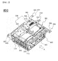
FIG. 1 is an exemplary perspective view of a conventional battery pack including a single battery module as an example of a battery pack having the above structure. - Referring to
FIG. 1 , abattery pack 100 includesunit modules 10, each of which has secondary batteries mounted therein, alower plate 20, a pair ofside support members 30, and a pair oftop support members 40. - The
unit modules 10 are stacked at the top of thelower plate 20 in a state in which theunit modules 10 are vertically erected. Theside support members 30 are disposed in close contact with the outer sides of theoutermost unit modules 10 in a state in which the lower end of each of theside support members 30 is fixed to thelower plate 20. - The
top support members 40 are connected between the upper parts of theside support members 30 to interconnect and support theside support members 30. - However, the battery pack with the above construction has a small capacity since the battery pack includes only a single battery module. Thus, it is difficult to apply the battery pack with the above construction to external devices such as vehicles that require high power and large capacity.
- Therefore, there is a great need to provide a battery pack that includes battery modules arranged in two or more rows to achieve high power and large capacity and has a specific structure in which durability of the battery pack can be secured against vibration and impact and the battery pack can be compactly constructed.
- Therefore, the present invention has been made to solve the above and other technical problems that have yet to be resolved.
- Specifically, it is an object of the present invention to provide a battery pack wherein each of first upper mounting members, a second upper mounting member and a rear mounting member has the shape of an angular pipe that is angular in vertical section, such that it is possible to minimize deformation due to vertical vibration and impact.
- It is another object of the present invention to provide a battery pack wherein battery modules are assembled upwardly to the first upper mounting members and the second upper mounting member which are each formed of an angular pipe structure, such that the mass of the battery pack is supported by the angular pipe structure and the battery pack is compactly constructed.
- It is another object of the present invention to provide a battery pack wherein a portion of the battery pack is formed using a part of the structure of a vehicle, such that it is possible to stably install the battery pack in the vehicle while minimizing the volume of the battery pack in the vehicle.
- In accordance with the present invention, the above and other objects can be accomplished by the provision of a battery pack including (a) a battery module array having battery modules arranged in two or more rows, each of the battery modules having a structure in which battery cells or unit modules, each having two or more battery cells mounted therein, are stacked in a state in which the battery cells or the unit modules are erected in an upside-down fashion, (b) a pair of side support members (a front support member and a rear support member) that support the front and rear of the battery module array, respectively, in a state in which the pair of side support members are in close contact with outermost unit modules in the battery modules in the battery module array, (c) lower end support members coupled to lower ends of the side support members to support a lower end of the battery module array, (d) two or more first upper mounting members coupled to upper ends of the side support members and lower ends of the battery modules erected in an upside-down fashion, each of the first upper mounting members being fastened at one end thereof to an external device and having the shape of an angular pipe that is angular in vertical section, (e) a second upper mounting member coupled to upper ends of the first upper mounting members such that the second upper mounting member intersects the first upper mounting members at right angles, the second upper mounting member being fastened at opposite ends thereof to the external device and having the shape of an angular pipe that is angular in vertical section, and (f) a rear mounting member disposed at the rear of the battery module array, the rear mounting member being fastened at opposite ends thereof to the external device and having the shape of an angular pipe that is angular in vertical section.
- In the battery pack according to the present invention, each of the first upper mounting members and the second upper mounting member has the shape of an angular pipe that is angular in vertical section. Therefore, deformation of the battery pack due to vibration and impact is minimized by the angular pipe having a high moment of inertia.
- In addition, the pair of side support members support the front and rear of the battery module array, respectively. Therefore, it is possible to securely increase bending rigidity of the lower end support member coupled to the lower ends of the side support members and to sufficiently secure overall structural reliability of the battery pack against vertical vibration.
- Further, the opposite ends of each of the rear mounting member and the second upper mounting member and the one ends of the first upper mounting members are fastened to the external device. Therefore, it is possible to easily and stably mount the battery pack to the external device even when the battery pack is located below the fastening position at which the battery pack is fastened to the external device.
- In addition, since the battery modules, each of which has a structure in which unit modules are stacked in a state in which the unit modules are erected in an upside-down fashion, are arranged in two or more rows, it is possible to secure structural stability of the battery pack and to provide high power and large capacity as compared to the structure of the conventional battery pack which includes a single battery module.
- For reference, the side support members will also be referred to as a "front support member" and a "rear support member" that support the front and rear of the battery module array, respectively, as needed in this specification. Directions mentioned in this specification will be expressed as front, rear, left, right, top and bottom in a state in which the battery module array is viewed from the front support member that is in close contact with the battery module array.
- In the present invention, each of the unit modules may be a secondary battery or a small-scale module having two or more secondary batteries mounted therein. An example of a unit module having two or more secondary batteries mounted therein is described in Korean Patent Application No.
2006-12303 - Other examples of the unit module are described in Korean Patent Application No.
2006-20772 2006-45444 - The disclosures of the above patent applications are incorporated herein by reference. Of course, however, the structure of each of the unit modules of each battery module according to the present invention is not limited to the above examples of the unit modules described in the above patent applications.
- Preferably, each of the battery cells is a plate-shaped battery cell, which provides a high stack rate in a limited space. For example, each of the battery cells may be structured such that an electrode assembly is mounted in a battery case formed of a laminate sheet.
- Specifically, each of the battery cells is a pouch-shaped secondary battery in which an electrode assembly having a cathode/separator/anode structure is sealed, together with an electrolyte, within a battery case. For example, each of the battery cells is a plate-shaped secondary battery with an approximately rectangular parallelepiped structure having a small thickness to width ratio. Generally, the pouch-shaped secondary battery includes a pouch-shaped battery case. The battery case has a laminate sheet structure in which an outer coating layer formed of a polymer resin exhibiting high durability, a barrier layer formed of a metallic material blocking moisture or air, and an inner sealant layer formed of a thermally-weldable polymer resin are sequentially stacked.
- The angular pipe may have the shape of a hollow quadrangular bar or a closed quadrangular bar. Preferably, the angular pipe has the shape of a hollow quadrangular bar. Such shapes have a high moment of inertia, increasing shock resistance against vibration of the battery pack, as compared to a conventional frame that is I-shaped or is formed of a plate bent in a specific shape. The above term "quadrangular bar shape" may be construed as including not only a quadrangular shape but also a shape having sharp corners, a shape having rounded corners, a shape having one or two linear sides, or a shape having one or two gently-curved sides.
- Each of the side support members preferably includes a main body that is in contact with outermost unit modules in the battery modules in the battery module array, an upper end wall and a lower end wall, each being shaped to protrude outwardly from the perimeter of the main body, and a pair of side walls to disperse pressure (or bending load) applied by the battery modules and the lower end support member. Here, the term "outwardly" refers to a direction opposite to the direction of the pressure, i.e., a direction opposite to the direction from the main body of the side support member to the battery modules and the lower end support member.
- In the battery pack according to the present invention, the battery modules erected in an upside-down fashion are brought into close contact with each other by the side support members, in a state in which the lower ends of the battery modules are coupled to the first upper mounting members, and the side support members are fixed by the lower end support member. Therefore, it is possible to prevent the unit modules of each of the battery modules from swelling and moving in the thickness direction thereof, thereby improving safety of the battery modules and effectively preventing deterioration in performance of the battery modules.
- In a preferred example of the above structure, the upper end walls of the side support members may be coupled to the first upper mounting members by welding or bolting.
- Meanwhile, the shape of each of the side support members is not particularly limited so long as the side support members can easily support the front and rear of the battery module array. For example, each of the side support members may have a rectangular shape in plan view.
- A lower plate, opposite ends of which are coupled to the side support members, may be further mounted to lower parts of the lower end support members to prevent downward movement of the battery module array in cooperation with the lower end support member when external force is applied to the battery pack.
- In a preferred example, when the battery modules are arranged in two rows to constitute a battery module array, the lower end support members may include four members to support the lower ends of the opposite sides of each of the battery modules.
- The structure of each of the first upper mounting members is not particularly limited so long as the lower ends of the battery modules erected in an upside-down fashion can be easily mounted to the first upper mounting members. For example, the first upper mounting members may include two opposite end members coupled to upper parts of opposite sides of the battery module array and a middle member coupled to the middle of the battery module array. Therefore, the first upper mounting members can uniformly support the mass of the battery module array.
- The end of each of the first upper mounting members fastened to the external device is preferably bent upward by the height of the second upper mounting member coupled to the upper ends of the first upper mounting members, such that the ends of the first upper mounting members and the top of the second upper mounting member are positioned at the same level.
- Where appropriate, the battery pack may further include an upper plate mounted between the battery module array and the first upper mounting members to reinforce the top of the battery module array.
- In an example of the above structure, the battery module array may be coupled to the upper plate fixed to the lower ends of the first upper mounting members such that the first upper mounting members support the mass of the battery module array.
- In another example, portions of the upper plate corresponding to the first upper mounting members may be recessed to lower the overall height of the battery pack.
- Meanwhile, the battery pack generally includes an electrically wired structure. Thus, the lower plate may extend to the rear of the rear mounting member to secure a space through which a wire, such as an electric wire, extends.
- Where appropriate, the other ends of the first upper mounting members may be coupled to the upper end of the rear mounting member to increase coupling force between the first upper mounting members and the rear mounting member.
- In another example, the battery pack may further include a reinforcing bracket coupled to the upper ends of the first upper mounting members, the reinforcing bracket being mounted parallel to the second upper mounting member, to further reinforce the coupling structure between the first upper mounting members and the second upper mounting member.
- The battery pack may further include a U-shaped bracket mounted to the upper end of at least one of the first upper mounting members to fix a safety plug.
- In an example, the structure of the rear mounting member is not particularly limited so long as the rear mounting member can easily cover opposite sides and the bottom of a cooling fan mounted to the rear of the battery module array. Preferably, the rear mounting member has a U-shaped frame structure.
- In another example, the opposite ends of the rear mounting member may be bent parallel to the second upper mounting member and fastening holes may be formed at the bent portions of the rear mounting member to achieve easy coupling to the external device.
- The present invention also provides an electric vehicle, a hybrid electric vehicle or a plug-in hybrid electric vehicle that uses the above battery pack as a power source, has a limited installation space, and is exposed to frequent vibration and strong impact.
- Of course, the battery pack used as a power source of the vehicle may be manufactured by combining battery modules based on desired power and capacity.
- In this case, the vehicle may be an electric vehicle, a hybrid electric vehicle, or a plug-in hybrid electric vehicle wherein the battery pack is installed in the lower part of a trunk of the vehicle or between a rear seat and the trunk of the vehicle.
- The battery pack according to the present invention is structured such that the size of the top of the battery pack is greater than that of the bottom. Therefore, the battery pack is preferably installed in a spare tire space under the trunk of the vehicle.
- The electric vehicle, the hybrid electric vehicle, the plug-in hybrid electric vehicle or the like that use the battery pack as a power source thereof are well known in the art and therefore a detailed description thereof will not be given.
- The above and other objects, features and other advantages of the present invention will be more clearly understood from the following detailed description taken in conjunction with the accompanying drawings, in which:
-
FIG. 1 is a perspective view of a conventional battery pack; -
FIG. 2 is a perspective view of a battery pack according to one embodiment of the present invention; -
FIG. 3 is a rear perspective view of the battery pack ofFIG. 2 ; -
FIG. 4 is a side perspective view of the battery pack ofFIG. 2 ; -
FIG. 5 is a top perspective view of the battery pack ofFIG. 2 ; -
FIG. 6 is a perspective view of a structure of the battery pack in which battery modules are erected in an upside-down fashion; and -
FIG. 7 is a front perspective view of the battery pack ofFIG. 2 . - Now, embodiments of the present invention will be described in detail with reference to the accompanying drawings. However, it should be noted that the description of the embodiments is given to provide better understanding of the present invention without limiting the scope of the invention.
-
FIG. 2 is a schematic perspective view of a battery pack according to an embodiment of the present invention andFIG. 3 is a schematic rear perspective view of the battery pack ofFIG. 2 . -
FIG. 4 is a schematic side perspective view of the battery pack ofFIG. 2 andFIG. 5 is a schematic top perspective view of the battery pack ofFIG. 2 . - As shown in
FIGS. 2 to 5 , abattery pack 800 includes abattery module array 200, a pair of side support members (i.e., afront support member 400 and a rear support member 410), a lowerend support member 600, three first upper mountingmembers 300, a secondupper mounting member 310 and arear mounting member 500. - The
battery module array 200 includesbattery modules battery modules front support member 400 and therear support member 410 support the front and rear of thebattery module array 200, respectively, in a state in which thefront support member 400 and therear support member 410 are in close contact with outermost unit modules in the battery modules in thebattery module array 200. - The lower
end support members 600 are coupled to the lower ends of thefront support member 400 and therear support member 410 to support the lower end of thebattery module array 200. - The first upper mounting
members 300 are coupled to the upper ends of thefront support member 400 and therear support member 410 and the lower ends of thebattery modules fastening holes 308 formed in one ends 306 of the first upper mountingmembers 300. - The second
upper mounting member 310 intersects the first upper mountingmembers 300 at right angles. The secondupper mounting member 310 is coupled to the upper ends of the first upper mountingmembers 300 and is fastened to an external device (for example, a vehicle) throughfastening holes 308 formed in opposite ends 312 and 314 of the second upper mountingmembers 310. - The
rear mounting member 500 is located at the rear of thebattery module array 200 and is fastened to the external device throughfastening holes 506 formed in opposite ends 502 and 504 of therear mounting member 500. - Each of the first upper mounting
members 300, the secondupper mounting member 310 and therear mounting member 500 has the shape of an angular pipe that is angular in vertical section and, specifically, has the shape of a hollow quadrangular bar. - Each of the
front support member 400 and therear support member 410 has a rectangular shape in plan view and includes a main body that is in contact with outermost unit modules in the battery modules in thebattery module array 200, an upper end wall and a lower end wall, each being shaped to protrude outwardly from the perimeter of the main body, and a pair of side walls. - The upper end wall of the
front support member 400 is coupled to the first upper mountingmembers 300 by bolting. - The
lower plate 710 are mounted to lower parts of the lowerend support members 600 in a state in which opposite ends of thelower plate 710 are coupled to thefront support member 400 and therear support member 410, respectively. Thelower plate 710 extends to the rear of therear mounting member 500 to secure a space through which a wire (not shown) extends. - The lower
end support member 600 includes four members that support lower ends of opposite sides of thebattery modules - The first upper mounting
members 300 include twoopposite end members battery module array 200 and amiddle member 305 coupled to the middle of thebattery module array 200. The ends 306 of the first upper mountingmembers 300, at which the first upper mountingmembers 300 are fastened to the external device, are preferably bent upward by the height of the secondupper mounting member 310. - An
upper plate 700 is mounted between thebattery module array 200 and the first upper mountingmembers 300. Thebattery module array 200 is coupled to theupper plate 700 fixed to lower ends of the first upper mountingmembers 300 such that the first upper mountingmembers 300 support the mass of thebattery module array 200. - The
upper plate 700 is recessed at portions thereof corresponding to the first upper mountingmembers 300. - A reinforcing
bracket 720 is mounted parallel to the secondupper mounting member 310 in a state in which the reinforcingbracket 720 is coupled to upper ends of the first upper mountingmembers 300. AU-shaped bracket 730 is mounted to the upper end of themiddle member 305 to fix a safety plug (not shown). - The
rear mounting member 500 has a U-shaped frame structure to cover the bottom and opposite sides of a cooling fan (not shown) mounted to the rear of thebattery module array 200. - The opposite ends 502 and 504 of the
rear mounting member 500 are bent parallel to the secondupper mounting member 310 andfastening holes 506 are formed at the bent portions of therear mounting member 500 to achieve easy coupling to the external device. - At the rear of the
battery pack 800, the reinforcingbracket 520 is coupled to therear support member 410 and therear mounting member 500 to prevent the battery pack from swinging in a front-rear direction (denoted by an arrow). -
FIG. 6 is a schematic perspective view of a structure of the battery pack in which battery modules are erected in an upside-down fashion andFIG. 7 is a schematic front perspective view of the battery pack ofFIG. 2 . - As shown in
FIGS. 6 and7 ,unit modules upper mounting member 300 in a state in which theunit modules - To determine vibration characteristics of the battery pack of
FIG. 2 in a structure (structure 1) in which the first upper mounting members and the second upper mounting member are each formed of a general frame and in a structure (structure 2) in which the first upper mounting members and the second upper mounting member are each formed of an angular pipe, resonance point detection analysis was carried out in three deformation modes in which external force was applied to the battery pack in a lateral direction, in a front-rear direction and in a vertical direction, respectively. Results are shown in Table 1 below.Table 1 Deformation Mode Battery Pack Structure Resonant Frequency Lateral deformation mode Structure 1 29.5 Hz Structure 2 34.5 Hz Front-rear deformation mode Structure 1 49.8 Hz Structure 2 53.7 Hz Vertical deformation mode Structure 1 55.9 Hz Structure 2 65.5 Hz - As can be seen from Table 1, since battery modules are fixed to the first upper mounting members and the second upper mounting member that are each formed of an angular pipe in structure 2, the structural reliability of structure 2 is greatly improved even when the battery pack vibrates at a high rate in each of the deformation modes, as compared to structure 1 in which battery modules are fixed to the first upper mounting members and the second upper mounting member that are each formed of a frame.
- The experimental results unexpectedly showed that durability of the battery pack can be greatly improved simply by forming the first upper mounting members and the second upper mounting member using angular pipes that have a high moment of inertia.
- The battery pack according to the present invention can be practically applied to a vehicle that uses a battery pack having a weight of 30 kg or greater as a power source and that is subject to vertical vibration.
- It will be apparent to those skilled in the art that various modifications and variations are possible in light of the above teaching without departing from the scope of the invention.
- As is apparent from the above description, as compared to the structure of the conventional battery pack which includes a single battery module, a battery pack according to the present invention can provide high power and large capacity since battery modules are arrayed in two or more rows in the battery pack and can also minimize deformation due to vertical vibration and impact since each of the first upper mounting members and the second upper mounting member has the shape of an angular pipe that is angular in vertical section.
- In addition, battery modules are assembled upwardly to the first upper mounting members and the second upper mounting member which are each formed of an angular pipe structure. Therefore, the mass of the battery pack can be supported by the angular pipe structure and the battery pack can be compactly constructed.
- Moreover, it is possible to stably install the battery pack in a vehicle while minimizing the volume of the battery pack in the vehicle since a portion of the battery pack is formed using a part of the structure of the vehicle.
Claims (22)
- A battery pack comprising:(a) a battery module array having battery modules arranged in two or more rows, each of the battery modules having a structure in which battery cells or unit modules, each having two or more battery cells mounted therein, are stacked in a state in which the battery cells or the unit modules are erected in an upside-down fashion;(b) a pair of side support members (a front support member and a rear support member) that support the front and rear of the battery module array, respectively, in a state in which the pair of side support members are in close contact with outermost unit modules in the battery modules in the battery module array;(c) lower end support members coupled to lower ends of the side support members to support a lower end of the battery module array;(d) two or more first upper mounting members coupled to upper ends of the side support members and lower ends of the battery modules erected in an upside-down fashion, each of the first upper mounting members being fastened at one end thereof to an external device and having the shape of an angular pipe that is angular in vertical section;(e) a second upper mounting member coupled to upper ends of the first upper mounting members such that the second upper mounting member intersects the first upper mounting members at right angles, the second upper mounting member being fastened at opposite ends thereof to the external device and having the shape of an angular pipe that is angular in vertical section; and(f) a rear mounting member disposed at the rear of the battery module array, the rear mounting member being fastened at opposite ends thereof to the external device and having the shape of an angular pipe that is angular in vertical section.
- The battery pack according to claim 1, wherein each of the battery cells is a plate-shaped battery cell.
- The battery pack according to claim 1, wherein each of the battery cells is structured such that an electrode assembly is mounted in a laminated battery case.
- The battery pack according to claim 1, wherein the angular pipe is a hollow quadrangular bar.
- The battery pack according to claim 1, wherein each of the side support members comprises:a main body that is in contact with the outermost unit modules in the battery modules in the battery module array;an upper end wall and a lower end wall, each being shaped to protrude outwardly from the perimeter of the main body; anda pair of side walls.
- The battery pack according to claim 5, wherein the upper end walls of the side support members are coupled to the first upper mounting members by welding or bolting.
- The battery pack according to claim 1, wherein each of the side support members has a rectangular shape in plan view.
- The battery pack according to claim 1, further comprising a lower plate mounted to lower parts of the lower end support members, the lower plate being coupled at opposite ends thereof to the side support members.
- The battery pack according to claim 1, wherein the lower end support members comprise four members that support lower ends of opposite sides of the battery modules.
- The battery pack according to claim 1, wherein the first upper mounting members comprise two opposite end members coupled to upper parts of opposite sides of the battery module array and a middle member coupled to a middle of the battery module array.
- The battery pack according to claim 1, wherein the end of each of the first upper mounting members fastened to the external device is bent upward by the height of the second upper mounting member.
- The battery pack according to claim 1, further comprising an upper plate mounted between the battery module array and the first upper mounting members.
- The battery pack according to claim 12, wherein the battery module array is coupled to the upper plate fixed to lower ends of the first upper mounting members such that the first upper mounting members support the mass of the battery module array.
- The battery pack according to claim 12, wherein the upper plate is recessed at portions thereof corresponding to the first upper mounting members.
- The battery pack according to claim 8, wherein the lower plate extends to the rear of the rear mounting member to secure a space through which a wire extends.
- The battery pack according to claim 1, wherein the other end of each of the first upper mounting members is coupled to an upper end of the rear mounting member.
- The battery pack according to claim 1, further comprising a reinforcing bracket coupled to upper ends of the first upper mounting members, the reinforcing bracket being mounted parallel to the second upper mounting member.
- The battery pack according to claim 1, further comprising a U-shaped bracket mounted to the upper end of at least one of the first upper mounting members to fix a safety plug.
- The battery pack according to claim 1, wherein the rear mounting member has a U-shaped frame structure to cover opposite sides and the bottom of a cooling fan mounted to the rear of the battery module array.
- The battery pack according to claim 1, wherein the opposite ends of the rear mounting member are bent parallel to the second upper mounting member and fastening holes are formed at the bent portions of the rear mounting member to achieve easy coupling to the external device.
- An electric vehicle, a hybrid electric vehicle or a plug-in hybrid electric vehicle comprising the battery pack according to claim 1 as a power source.
- The electric vehicle, the hybrid electric vehicle or the plug-in hybrid electric vehicle according to claim 21, wherein the battery pack is installed in a lower part of a trunk of the vehicle or between a rear seat and the trunk of the vehicle.
Applications Claiming Priority (2)
| Application Number | Priority Date | Filing Date | Title |
|---|---|---|---|
| KR20110047134 | 2011-05-19 | ||
| PCT/KR2012/003150 WO2012157857A2 (en) | 2011-05-19 | 2012-04-24 | Battery pack having excellent structural reliability |
Publications (3)
| Publication Number | Publication Date |
|---|---|
| EP2682999A2 true EP2682999A2 (en) | 2014-01-08 |
| EP2682999A4 EP2682999A4 (en) | 2014-07-30 |
| EP2682999B1 EP2682999B1 (en) | 2017-01-11 |
Family
ID=47177422
Family Applications (2)
| Application Number | Title | Priority Date | Filing Date |
|---|---|---|---|
| EP12785676.3A Active EP2682999B1 (en) | 2011-05-19 | 2012-04-24 | Battery pack having excellent structural reliability |
| EP12785976.7A Active EP2685522B1 (en) | 2011-05-19 | 2012-05-17 | Battery pack having excellent structural reliability |
Family Applications After (1)
| Application Number | Title | Priority Date | Filing Date |
|---|---|---|---|
| EP12785976.7A Active EP2685522B1 (en) | 2011-05-19 | 2012-05-17 | Battery pack having excellent structural reliability |
Country Status (6)
| Country | Link |
|---|---|
| US (2) | US8708080B2 (en) |
| EP (2) | EP2682999B1 (en) |
| JP (2) | JP5711852B2 (en) |
| KR (1) | KR101272055B1 (en) |
| CN (2) | CN103493244B (en) |
| WO (2) | WO2012157857A2 (en) |
Cited By (1)
| Publication number | Priority date | Publication date | Assignee | Title |
|---|---|---|---|---|
| CN109305022A (en) * | 2018-09-28 | 2019-02-05 | 上汽通用五菱汽车股份有限公司 | Protective device |
Families Citing this family (35)
| Publication number | Priority date | Publication date | Assignee | Title |
|---|---|---|---|---|
| CN102467204A (en) * | 2010-11-18 | 2012-05-23 | 鸿富锦精密工业(深圳)有限公司 | Fan fixing device |
| KR101307369B1 (en) * | 2011-05-23 | 2013-09-11 | 주식회사 엘지화학 | Battery Pack of Improved Safety |
| KR102122926B1 (en) * | 2012-12-05 | 2020-06-15 | 에스케이이노베이션 주식회사 | Battery Sub-Pack and a Method for manufacturing the same |
| KR101709555B1 (en) | 2013-07-31 | 2017-02-23 | 주식회사 엘지화학 | Battery Module Assembly Having Coolant Flow Channel |
| WO2015141997A1 (en) * | 2014-03-18 | 2015-09-24 | 주식회사 엘지화학 | Positive electrode active material and lithium secondary battery comprising same |
| CN103832258B (en) * | 2014-03-20 | 2016-05-18 | 山东梅亿邦赛电动车制造有限公司 | Electric automobile power battery fast replacing structure |
| KR101506422B1 (en) * | 2014-04-16 | 2015-03-27 | 지엠 글로벌 테크놀러지 오퍼레이션스 엘엘씨 | An apparatus for protecting the batteries of an electronic vehicle |
| US9561713B2 (en) * | 2014-12-28 | 2017-02-07 | Skylar Netherland | Systems and methods for a mounting device for vehicles |
| DE102015003643B3 (en) | 2015-03-19 | 2016-06-16 | Audi Ag | motor vehicle |
| FR3041906B1 (en) * | 2015-10-05 | 2017-11-03 | Renault Sas | BATTERY SUPPORT ARRANGEMENT FOR A HYBRID VEHICLE. |
| KR102092110B1 (en) * | 2015-12-04 | 2020-03-23 | 주식회사 엘지화학 | Battery Pack Comprising Connecting Bracket for Battery Module Groups Spaced Apart |
| US10232699B2 (en) | 2015-12-21 | 2019-03-19 | Kubota Corporation | Work vehicle |
| JP6215905B2 (en) * | 2015-12-22 | 2017-10-18 | 本田技研工業株式会社 | Car body rear structure |
| KR101762276B1 (en) * | 2016-01-26 | 2017-07-28 | 현대자동차주식회사 | Mounting structure of battery and spare tire for vehicle |
| KR102097083B1 (en) * | 2016-01-28 | 2020-04-03 | 주식회사 엘지화학 | Battery pack case and battery pack including the battery pack case, car |
| FR3047469B1 (en) * | 2016-02-09 | 2018-02-23 | Renault S.A.S. | DEVICE FOR SUPPORTING A COMPONENT OF A MOTOR VEHICLE |
| WO2018033880A2 (en) | 2016-08-17 | 2018-02-22 | Shape Corp. | Battery support and protection structure for a vehicle |
| EP3566253B1 (en) | 2017-01-04 | 2022-12-28 | Shape Corp. | Battery support structure for a vehicle |
| US10483510B2 (en) | 2017-05-16 | 2019-11-19 | Shape Corp. | Polarized battery tray for a vehicle |
| US11211656B2 (en) | 2017-05-16 | 2021-12-28 | Shape Corp. | Vehicle battery tray with integrated battery retention and support feature |
| WO2018213306A1 (en) | 2017-05-16 | 2018-11-22 | Shape Corp. | Vehicle battery tray having tub-based component |
| DE102017215113B4 (en) * | 2017-08-30 | 2019-06-19 | Ford Global Technologies, Llc | motor vehicle |
| WO2019055658A2 (en) | 2017-09-13 | 2019-03-21 | Shape Corp. | Vehicle battery tray with tubular peripheral wall |
| US10661646B2 (en) | 2017-10-04 | 2020-05-26 | Shape Corp. | Battery tray floor assembly for electric vehicles |
| US10434894B2 (en) * | 2018-01-23 | 2019-10-08 | Gm Global Technology Operations Llc. | Vehicle battery pack assembly |
| JP7101489B2 (en) * | 2018-02-01 | 2022-07-15 | アイシン軽金属株式会社 | Vehicle mounting structure of battery module |
| EP3759761A4 (en) | 2018-03-01 | 2021-09-08 | Shape Corp. | Cooling system integrated with vehicle battery tray |
| US11688910B2 (en) | 2018-03-15 | 2023-06-27 | Shape Corp. | Vehicle battery tray having tub-based component |
| FR3086804B1 (en) | 2018-09-28 | 2020-09-11 | Psa Automobiles Sa | TRACTION BATTERY BLOCK OF A VEHICLE WITH CELLS DIRECTLY INTEGRATED IN THE BLOCK |
| US10864810B2 (en) * | 2019-04-25 | 2020-12-15 | Fca Us Llc | Bowstring-truss battery cradle system |
| KR102633309B1 (en) * | 2019-06-26 | 2024-02-06 | 현대자동차주식회사 | Vehicle body structure and vehicle including the same |
| KR20210043990A (en) * | 2019-10-14 | 2021-04-22 | 주식회사 엘지화학 | Battery pack and manufacturing method thereof |
| US11600880B2 (en) * | 2020-09-01 | 2023-03-07 | Beta Air, Llc | System and method for securing battery in aircraft |
| CN114204153A (en) * | 2020-09-17 | 2022-03-18 | 奥动新能源汽车科技有限公司 | Vertical butt joint type vehicle end liquid cooling connecting device, battery installation part and electric automobile |
| JP2022143365A (en) * | 2021-03-17 | 2022-10-03 | 株式会社Subaru | Protective construction of on-vehicle battery |
Citations (4)
| Publication number | Priority date | Publication date | Assignee | Title |
|---|---|---|---|---|
| KR20080047641A (en) * | 2006-11-27 | 2008-05-30 | 주식회사 엘지화학 | Power supply system having heat radiation-preventing structure |
| EP2214225A1 (en) * | 2007-11-21 | 2010-08-04 | Honda Motor Co., Ltd. | Electric power source device for vehicle |
| WO2011001926A1 (en) * | 2009-06-29 | 2011-01-06 | アイシン軽金属株式会社 | Frame structure for mounting a vehicle battery module in a vehicle |
| EP2634834A2 (en) * | 2010-10-27 | 2013-09-04 | LG Chem, Ltd. | Battery pack having improved durability |
Family Cites Families (52)
| Publication number | Priority date | Publication date | Assignee | Title |
|---|---|---|---|---|
| US5390754A (en) * | 1992-01-16 | 1995-02-21 | Honda Giken Kogyo Kabushiki Kaisha | Battery box for an electric vehicle |
| US5501289A (en) * | 1993-01-22 | 1996-03-26 | Nissan Motor Co., Ltd. | Floor structure of electric vehicle |
| JP3480286B2 (en) * | 1997-12-08 | 2003-12-15 | 日産自動車株式会社 | Battery frame structure for electric vehicles |
| JP3842204B2 (en) * | 2002-11-11 | 2006-11-08 | 本田技研工業株式会社 | Front body structure |
| JP4078998B2 (en) * | 2003-02-04 | 2008-04-23 | トヨタ自動車株式会社 | Vehicle battery mounting structure |
| KR20060012303A (en) | 2003-05-19 | 2006-02-07 | 쇼와 덴코 가부시키가이샤 | Heat exchanger fin, heat exchanger, condensers, and evaporators |
| US7051825B2 (en) * | 2003-05-21 | 2006-05-30 | Honda Motor Co., Ltd. | Structure for installing high-voltage equipment component to vehicle |
| US7264277B2 (en) * | 2004-01-22 | 2007-09-04 | Honda Motor Co., Ltd. | Gaseous fuel vehicle rear structure |
| JP4649849B2 (en) * | 2004-03-02 | 2011-03-16 | トヨタ自動車株式会社 | Storage mechanism mounting structure |
| KR20060020772A (en) | 2004-09-01 | 2006-03-07 | 엘지전자 주식회사 | Dust and dirt collecting unit for vacuum cleaner |
| US7503585B2 (en) * | 2004-09-08 | 2009-03-17 | Nissan Motor Co., Ltd. | Rear vehicle structure |
| JP2006185815A (en) * | 2004-12-28 | 2006-07-13 | Toyota Motor Corp | Battery pack |
| JP4385020B2 (en) * | 2005-06-02 | 2009-12-16 | 本田技研工業株式会社 | Vehicle power supply |
| JP4673692B2 (en) * | 2005-07-19 | 2011-04-20 | 本田技研工業株式会社 | Cooling structure for electrical equipment in vehicles |
| US7413045B2 (en) * | 2005-11-30 | 2008-08-19 | Karma Medical Products Co., Ltd. | Battery quick-release structure for an electric mobility scooter |
| US7270208B2 (en) * | 2005-12-30 | 2007-09-18 | Taiwan An I Co., Ltd. | Battery carrier sliding device of an electrical wheel chair |
| KR100861713B1 (en) | 2006-02-09 | 2008-10-06 | 주식회사 엘지화학 | Battery Module |
| JP5141026B2 (en) * | 2006-02-27 | 2013-02-13 | トヨタ自動車株式会社 | In-vehicle structure of power storage pack |
| JP4935112B2 (en) * | 2006-02-28 | 2012-05-23 | トヨタ自動車株式会社 | In-vehicle structure of power storage pack |
| WO2007102672A1 (en) * | 2006-03-06 | 2007-09-13 | Lg Chem, Ltd. | Battery module |
| KR100948002B1 (en) | 2006-03-06 | 2010-03-18 | 주식회사 엘지화학 | Middle or Large-sized Battery Module |
| US7875378B2 (en) | 2006-03-06 | 2011-01-25 | Lg Chem, Ltd. | Voltage sensing member and battery module employed with the same |
| KR100870457B1 (en) * | 2006-05-22 | 2008-11-25 | 주식회사 엘지화학 | Battery Module |
| EP1897739B1 (en) * | 2006-09-07 | 2010-11-03 | Honda Motor Co., Ltd. | Electrical device cooling structure in vehicle |
| KR101217459B1 (en) * | 2006-09-25 | 2013-01-02 | 주식회사 엘지화학 | battery module assembly |
| KR100920207B1 (en) * | 2006-11-27 | 2009-10-06 | 주식회사 엘지화학 | Power Switching Module for Battery Module Assembly |
| KR101134403B1 (en) * | 2006-11-27 | 2012-04-09 | 주식회사 엘지화학 | Power Supply Device for Hybrid-Typed Electric Vehicle |
| JP4345812B2 (en) * | 2006-12-28 | 2009-10-14 | 三菱自動車工業株式会社 | Electric vehicle battery mounting structure |
| JP4420018B2 (en) * | 2006-12-28 | 2010-02-24 | 三菱自動車工業株式会社 | Electric vehicle battery mounting structure |
| JP4420017B2 (en) * | 2006-12-28 | 2010-02-24 | 三菱自動車工業株式会社 | Electric vehicle battery mounting structure |
| JP4434213B2 (en) * | 2007-01-26 | 2010-03-17 | 三菱自動車工業株式会社 | Electric vehicle battery mounting structure |
| DE102007023391B4 (en) * | 2007-05-18 | 2019-05-02 | Dr. Ing. H.C. F. Porsche Aktiengesellschaft | Protective housing for a vehicle battery and motor vehicle with such a protective housing |
| KR101141057B1 (en) * | 2007-06-28 | 2012-05-03 | 주식회사 엘지화학 | Middle or Large-sized Battery Pack |
| JP4308285B2 (en) * | 2007-07-17 | 2009-08-05 | 本田技研工業株式会社 | Subframe structure |
| KR101026745B1 (en) * | 2007-07-23 | 2011-04-08 | 주식회사 엘지화학 | Middle or Large-sized Battery Pack |
| JP5029263B2 (en) * | 2007-09-28 | 2012-09-19 | 三菱自動車工業株式会社 | Electric car |
| JP5151363B2 (en) * | 2007-09-28 | 2013-02-27 | 三菱自動車工業株式会社 | Battery case for electric vehicles |
| JP4386131B2 (en) * | 2007-12-05 | 2009-12-16 | 三菱自動車工業株式会社 | Electric car |
| JP4306783B2 (en) * | 2007-12-14 | 2009-08-05 | 三菱自動車工業株式会社 | Electric vehicle battery unit mounting structure |
| JP4283326B1 (en) * | 2007-12-25 | 2009-06-24 | 本田技研工業株式会社 | Battery cooling air intake structure |
| TWI338642B (en) * | 2008-02-07 | 2011-03-11 | Honda Motor Co Ltd | Vehicular power supply system |
| JP4319239B2 (en) * | 2008-02-07 | 2009-08-26 | 本田技研工業株式会社 | Hybrid vehicle |
| JP5042096B2 (en) * | 2008-03-25 | 2012-10-03 | 三洋電機株式会社 | Power supply for vehicle |
| JP2009238643A (en) * | 2008-03-27 | 2009-10-15 | Sanyo Electric Co Ltd | Battery block for vehicle |
| US20090267906A1 (en) * | 2008-04-25 | 2009-10-29 | Nokia Corporation | Touch sensitive apparatus |
| JP4769274B2 (en) * | 2008-07-07 | 2011-09-07 | 本田技研工業株式会社 | Car body rear structure |
| JP4919102B2 (en) * | 2008-11-17 | 2012-04-18 | 本田技研工業株式会社 | Cooling structure for power supply unit for vehicle |
| JP4478900B1 (en) * | 2008-12-03 | 2010-06-09 | 本田技研工業株式会社 | Capacitor heating device |
| US7913788B1 (en) * | 2010-02-09 | 2011-03-29 | Gm Global Technology Operations, Llc | Integrated energy storage and rear suspension assembly |
| DE102011102019B4 (en) * | 2010-06-02 | 2014-05-28 | Mazda Motor Corporation | Battery mounting structure for an electric motor vehicle |
| JP5648421B2 (en) * | 2010-10-26 | 2015-01-07 | マツダ株式会社 | Battery mounting structure for electric vehicles |
| KR20120059105A (en) * | 2010-11-30 | 2012-06-08 | 현대자동차주식회사 | Water drain apparatus of mounting high voltage battery pack in vehicle |
-
2012
- 2012-04-24 EP EP12785676.3A patent/EP2682999B1/en active Active
- 2012-04-24 WO PCT/KR2012/003150 patent/WO2012157857A2/en active Application Filing
- 2012-04-24 JP JP2014508285A patent/JP5711852B2/en active Active
- 2012-04-24 CN CN201280020167.3A patent/CN103493244B/en active Active
- 2012-05-17 CN CN201280020789.6A patent/CN103493247B/en active Active
- 2012-05-17 KR KR1020120052270A patent/KR101272055B1/en active IP Right Grant
- 2012-05-17 WO PCT/KR2012/003872 patent/WO2012157966A2/en active Application Filing
- 2012-05-17 JP JP2014505097A patent/JP5711850B2/en active Active
- 2012-05-17 EP EP12785976.7A patent/EP2685522B1/en active Active
-
2013
- 2013-08-26 US US13/975,756 patent/US8708080B2/en active Active
- 2013-08-28 US US14/012,368 patent/US8905171B2/en active Active
Patent Citations (4)
| Publication number | Priority date | Publication date | Assignee | Title |
|---|---|---|---|---|
| KR20080047641A (en) * | 2006-11-27 | 2008-05-30 | 주식회사 엘지화학 | Power supply system having heat radiation-preventing structure |
| EP2214225A1 (en) * | 2007-11-21 | 2010-08-04 | Honda Motor Co., Ltd. | Electric power source device for vehicle |
| WO2011001926A1 (en) * | 2009-06-29 | 2011-01-06 | アイシン軽金属株式会社 | Frame structure for mounting a vehicle battery module in a vehicle |
| EP2634834A2 (en) * | 2010-10-27 | 2013-09-04 | LG Chem, Ltd. | Battery pack having improved durability |
Non-Patent Citations (1)
| Title |
|---|
| See also references of WO2012157857A2 * |
Cited By (1)
| Publication number | Priority date | Publication date | Assignee | Title |
|---|---|---|---|---|
| CN109305022A (en) * | 2018-09-28 | 2019-02-05 | 上汽通用五菱汽车股份有限公司 | Protective device |
Also Published As
| Publication number | Publication date |
|---|---|
| EP2685522B1 (en) | 2016-10-19 |
| EP2682999B1 (en) | 2017-01-11 |
| WO2012157857A2 (en) | 2012-11-22 |
| US8708080B2 (en) | 2014-04-29 |
| US20130341111A1 (en) | 2013-12-26 |
| US8905171B2 (en) | 2014-12-09 |
| CN103493247B (en) | 2016-02-03 |
| CN103493244A (en) | 2014-01-01 |
| WO2012157966A3 (en) | 2013-03-28 |
| KR101272055B1 (en) | 2013-06-05 |
| EP2685522A4 (en) | 2014-07-30 |
| WO2012157857A3 (en) | 2013-01-17 |
| JP2014515870A (en) | 2014-07-03 |
| WO2012157966A9 (en) | 2012-12-20 |
| CN103493247A (en) | 2014-01-01 |
| JP5711850B2 (en) | 2015-05-07 |
| JP2014515867A (en) | 2014-07-03 |
| US20130333962A1 (en) | 2013-12-19 |
| EP2685522A2 (en) | 2014-01-15 |
| KR20120129790A (en) | 2012-11-28 |
| JP5711852B2 (en) | 2015-05-07 |
| EP2682999A4 (en) | 2014-07-30 |
| CN103493244B (en) | 2016-04-27 |
| WO2012157966A2 (en) | 2012-11-22 |
Similar Documents
| Publication | Publication Date | Title |
|---|---|---|
| EP2682999B1 (en) | Battery pack having excellent structural reliability | |
| US8728648B2 (en) | Battery pack of excellent structural stability | |
| EP2533320B1 (en) | Battery pack with a reinforcing member | |
| US8900736B2 (en) | Battery pack of improved durability | |
| US20130288095A1 (en) | Battery module of excellent structural stability | |
| KR101435441B1 (en) | Battery Pack Having Battery Module Arrangements Fixed by Supporting Members and Connection Members | |
| KR101233060B1 (en) | Battery Pack of Excellent Structural Stability |
Legal Events
| Date | Code | Title | Description |
|---|---|---|---|
| PUAI | Public reference made under article 153(3) epc to a published international application that has entered the european phase |
Free format text: ORIGINAL CODE: 0009012 |
|
| 17P | Request for examination filed |
Effective date: 20131003 |
|
| AK | Designated contracting states |
Kind code of ref document: A2 Designated state(s): AL AT BE BG CH CY CZ DE DK EE ES FI FR GB GR HR HU IE IS IT LI LT LU LV MC MK MT NL NO PL PT RO RS SE SI SK SM TR |
|
| RIN1 | Information on inventor provided before grant (corrected) |
Inventor name: CHOO, YEONSEOK Inventor name: LEE, BUMHYUN Inventor name: LEE, JIN KYU Inventor name: SHIN, YONG SHIK Inventor name: YOON, JONG MOON |
|
| A4 | Supplementary search report drawn up and despatched |
Effective date: 20140630 |
|
| RIC1 | Information provided on ipc code assigned before grant |
Ipc: B60L 11/18 20060101ALI20140624BHEP Ipc: H01M 2/10 20060101AFI20140624BHEP Ipc: H01M 2/02 20060101ALI20140624BHEP Ipc: B60K 1/04 20060101ALI20140624BHEP |
|
| DAX | Request for extension of the european patent (deleted) | ||
| RIC1 | Information provided on ipc code assigned before grant |
Ipc: H01M 2/10 20060101AFI20160714BHEP Ipc: B60L 11/18 20060101ALI20160714BHEP Ipc: H01M 10/0525 20100101ALN20160714BHEP Ipc: H01M 2/02 20060101ALI20160714BHEP Ipc: B60K 1/04 20060101ALI20160714BHEP |
|
| GRAP | Despatch of communication of intention to grant a patent |
Free format text: ORIGINAL CODE: EPIDOSNIGR1 |
|
| INTG | Intention to grant announced |
Effective date: 20160916 |
|
| GRAS | Grant fee paid |
Free format text: ORIGINAL CODE: EPIDOSNIGR3 |
|
| GRAA | (expected) grant |
Free format text: ORIGINAL CODE: 0009210 |
|
| AK | Designated contracting states |
Kind code of ref document: B1 Designated state(s): AL AT BE BG CH CY CZ DE DK EE ES FI FR GB GR HR HU IE IS IT LI LT LU LV MC MK MT NL NO PL PT RO RS SE SI SK SM TR |
|
| REG | Reference to a national code |
Ref country code: GB Ref legal event code: FG4D |
|
| REG | Reference to a national code |
Ref country code: CH Ref legal event code: EP |
|
| REG | Reference to a national code |
Ref country code: AT Ref legal event code: REF Ref document number: 862004 Country of ref document: AT Kind code of ref document: T Effective date: 20170115 |
|
| REG | Reference to a national code |
Ref country code: IE Ref legal event code: FG4D |
|
| REG | Reference to a national code |
Ref country code: DE Ref legal event code: R096 Ref document number: 602012027777 Country of ref document: DE |
|
| REG | Reference to a national code |
Ref country code: FR Ref legal event code: PLFP Year of fee payment: 6 |
|
| REG | Reference to a national code |
Ref country code: LT Ref legal event code: MG4D |
|
| REG | Reference to a national code |
Ref country code: NL Ref legal event code: MP Effective date: 20170111 |
|
| REG | Reference to a national code |
Ref country code: AT Ref legal event code: MK05 Ref document number: 862004 Country of ref document: AT Kind code of ref document: T Effective date: 20170111 |
|
| PG25 | Lapsed in a contracting state [announced via postgrant information from national office to epo] |
Ref country code: NL Free format text: LAPSE BECAUSE OF FAILURE TO SUBMIT A TRANSLATION OF THE DESCRIPTION OR TO PAY THE FEE WITHIN THE PRESCRIBED TIME-LIMIT Effective date: 20170111 |
|
| PG25 | Lapsed in a contracting state [announced via postgrant information from national office to epo] |
Ref country code: NO Free format text: LAPSE BECAUSE OF FAILURE TO SUBMIT A TRANSLATION OF THE DESCRIPTION OR TO PAY THE FEE WITHIN THE PRESCRIBED TIME-LIMIT Effective date: 20170411 Ref country code: LT Free format text: LAPSE BECAUSE OF FAILURE TO SUBMIT A TRANSLATION OF THE DESCRIPTION OR TO PAY THE FEE WITHIN THE PRESCRIBED TIME-LIMIT Effective date: 20170111 Ref country code: FI Free format text: LAPSE BECAUSE OF FAILURE TO SUBMIT A TRANSLATION OF THE DESCRIPTION OR TO PAY THE FEE WITHIN THE PRESCRIBED TIME-LIMIT Effective date: 20170111 Ref country code: IS Free format text: LAPSE BECAUSE OF FAILURE TO SUBMIT A TRANSLATION OF THE DESCRIPTION OR TO PAY THE FEE WITHIN THE PRESCRIBED TIME-LIMIT Effective date: 20170511 Ref country code: HR Free format text: LAPSE BECAUSE OF FAILURE TO SUBMIT A TRANSLATION OF THE DESCRIPTION OR TO PAY THE FEE WITHIN THE PRESCRIBED TIME-LIMIT Effective date: 20170111 Ref country code: GR Free format text: LAPSE BECAUSE OF FAILURE TO SUBMIT A TRANSLATION OF THE DESCRIPTION OR TO PAY THE FEE WITHIN THE PRESCRIBED TIME-LIMIT Effective date: 20170412 |
|
| PG25 | Lapsed in a contracting state [announced via postgrant information from national office to epo] |
Ref country code: AT Free format text: LAPSE BECAUSE OF FAILURE TO SUBMIT A TRANSLATION OF THE DESCRIPTION OR TO PAY THE FEE WITHIN THE PRESCRIBED TIME-LIMIT Effective date: 20170111 Ref country code: BG Free format text: LAPSE BECAUSE OF FAILURE TO SUBMIT A TRANSLATION OF THE DESCRIPTION OR TO PAY THE FEE WITHIN THE PRESCRIBED TIME-LIMIT Effective date: 20170411 Ref country code: PT Free format text: LAPSE BECAUSE OF FAILURE TO SUBMIT A TRANSLATION OF THE DESCRIPTION OR TO PAY THE FEE WITHIN THE PRESCRIBED TIME-LIMIT Effective date: 20170511 Ref country code: SE Free format text: LAPSE BECAUSE OF FAILURE TO SUBMIT A TRANSLATION OF THE DESCRIPTION OR TO PAY THE FEE WITHIN THE PRESCRIBED TIME-LIMIT Effective date: 20170111 Ref country code: ES Free format text: LAPSE BECAUSE OF FAILURE TO SUBMIT A TRANSLATION OF THE DESCRIPTION OR TO PAY THE FEE WITHIN THE PRESCRIBED TIME-LIMIT Effective date: 20170111 Ref country code: RS Free format text: LAPSE BECAUSE OF FAILURE TO SUBMIT A TRANSLATION OF THE DESCRIPTION OR TO PAY THE FEE WITHIN THE PRESCRIBED TIME-LIMIT Effective date: 20170111 Ref country code: LV Free format text: LAPSE BECAUSE OF FAILURE TO SUBMIT A TRANSLATION OF THE DESCRIPTION OR TO PAY THE FEE WITHIN THE PRESCRIBED TIME-LIMIT Effective date: 20170111 Ref country code: PL Free format text: LAPSE BECAUSE OF FAILURE TO SUBMIT A TRANSLATION OF THE DESCRIPTION OR TO PAY THE FEE WITHIN THE PRESCRIBED TIME-LIMIT Effective date: 20170111 |
|
| REG | Reference to a national code |
Ref country code: DE Ref legal event code: R097 Ref document number: 602012027777 Country of ref document: DE |
|
| PG25 | Lapsed in a contracting state [announced via postgrant information from national office to epo] |
Ref country code: EE Free format text: LAPSE BECAUSE OF FAILURE TO SUBMIT A TRANSLATION OF THE DESCRIPTION OR TO PAY THE FEE WITHIN THE PRESCRIBED TIME-LIMIT Effective date: 20170111 Ref country code: RO Free format text: LAPSE BECAUSE OF FAILURE TO SUBMIT A TRANSLATION OF THE DESCRIPTION OR TO PAY THE FEE WITHIN THE PRESCRIBED TIME-LIMIT Effective date: 20170111 Ref country code: SK Free format text: LAPSE BECAUSE OF FAILURE TO SUBMIT A TRANSLATION OF THE DESCRIPTION OR TO PAY THE FEE WITHIN THE PRESCRIBED TIME-LIMIT Effective date: 20170111 Ref country code: CZ Free format text: LAPSE BECAUSE OF FAILURE TO SUBMIT A TRANSLATION OF THE DESCRIPTION OR TO PAY THE FEE WITHIN THE PRESCRIBED TIME-LIMIT Effective date: 20170111 Ref country code: IT Free format text: LAPSE BECAUSE OF FAILURE TO SUBMIT A TRANSLATION OF THE DESCRIPTION OR TO PAY THE FEE WITHIN THE PRESCRIBED TIME-LIMIT Effective date: 20170111 |
|
| PLBE | No opposition filed within time limit |
Free format text: ORIGINAL CODE: 0009261 |
|
| STAA | Information on the status of an ep patent application or granted ep patent |
Free format text: STATUS: NO OPPOSITION FILED WITHIN TIME LIMIT |
|
| PG25 | Lapsed in a contracting state [announced via postgrant information from national office to epo] |
Ref country code: DK Free format text: LAPSE BECAUSE OF FAILURE TO SUBMIT A TRANSLATION OF THE DESCRIPTION OR TO PAY THE FEE WITHIN THE PRESCRIBED TIME-LIMIT Effective date: 20170111 Ref country code: SM Free format text: LAPSE BECAUSE OF FAILURE TO SUBMIT A TRANSLATION OF THE DESCRIPTION OR TO PAY THE FEE WITHIN THE PRESCRIBED TIME-LIMIT Effective date: 20170111 |
|
| REG | Reference to a national code |
Ref country code: CH Ref legal event code: PL |
|
| 26N | No opposition filed |
Effective date: 20171012 |
|
| REG | Reference to a national code |
Ref country code: IE Ref legal event code: MM4A |
|
| PG25 | Lapsed in a contracting state [announced via postgrant information from national office to epo] |
Ref country code: MC Free format text: LAPSE BECAUSE OF FAILURE TO SUBMIT A TRANSLATION OF THE DESCRIPTION OR TO PAY THE FEE WITHIN THE PRESCRIBED TIME-LIMIT Effective date: 20170111 |
|
| PG25 | Lapsed in a contracting state [announced via postgrant information from national office to epo] |
Ref country code: LI Free format text: LAPSE BECAUSE OF NON-PAYMENT OF DUE FEES Effective date: 20170430 Ref country code: SI Free format text: LAPSE BECAUSE OF FAILURE TO SUBMIT A TRANSLATION OF THE DESCRIPTION OR TO PAY THE FEE WITHIN THE PRESCRIBED TIME-LIMIT Effective date: 20170111 Ref country code: CH Free format text: LAPSE BECAUSE OF NON-PAYMENT OF DUE FEES Effective date: 20170430 Ref country code: LU Free format text: LAPSE BECAUSE OF NON-PAYMENT OF DUE FEES Effective date: 20170424 |
|
| REG | Reference to a national code |
Ref country code: BE Ref legal event code: MM Effective date: 20170430 |
|
| REG | Reference to a national code |
Ref country code: FR Ref legal event code: PLFP Year of fee payment: 7 |
|
| PG25 | Lapsed in a contracting state [announced via postgrant information from national office to epo] |
Ref country code: IE Free format text: LAPSE BECAUSE OF NON-PAYMENT OF DUE FEES Effective date: 20170424 |
|
| PG25 | Lapsed in a contracting state [announced via postgrant information from national office to epo] |
Ref country code: BE Free format text: LAPSE BECAUSE OF NON-PAYMENT OF DUE FEES Effective date: 20170430 |
|
| PG25 | Lapsed in a contracting state [announced via postgrant information from national office to epo] |
Ref country code: MT Free format text: LAPSE BECAUSE OF NON-PAYMENT OF DUE FEES Effective date: 20170424 |
|
| PG25 | Lapsed in a contracting state [announced via postgrant information from national office to epo] |
Ref country code: HU Free format text: LAPSE BECAUSE OF FAILURE TO SUBMIT A TRANSLATION OF THE DESCRIPTION OR TO PAY THE FEE WITHIN THE PRESCRIBED TIME-LIMIT; INVALID AB INITIO Effective date: 20120424 |
|
| PG25 | Lapsed in a contracting state [announced via postgrant information from national office to epo] |
Ref country code: CY Free format text: LAPSE BECAUSE OF NON-PAYMENT OF DUE FEES Effective date: 20170111 |
|
| PG25 | Lapsed in a contracting state [announced via postgrant information from national office to epo] |
Ref country code: MK Free format text: LAPSE BECAUSE OF FAILURE TO SUBMIT A TRANSLATION OF THE DESCRIPTION OR TO PAY THE FEE WITHIN THE PRESCRIBED TIME-LIMIT Effective date: 20170111 |
|
| PG25 | Lapsed in a contracting state [announced via postgrant information from national office to epo] |
Ref country code: TR Free format text: LAPSE BECAUSE OF FAILURE TO SUBMIT A TRANSLATION OF THE DESCRIPTION OR TO PAY THE FEE WITHIN THE PRESCRIBED TIME-LIMIT Effective date: 20170111 |
|
| PG25 | Lapsed in a contracting state [announced via postgrant information from national office to epo] |
Ref country code: AL Free format text: LAPSE BECAUSE OF FAILURE TO SUBMIT A TRANSLATION OF THE DESCRIPTION OR TO PAY THE FEE WITHIN THE PRESCRIBED TIME-LIMIT Effective date: 20170111 |
|
| REG | Reference to a national code |
Ref country code: DE Ref legal event code: R079 Ref document number: 602012027777 Country of ref document: DE Free format text: PREVIOUS MAIN CLASS: H01M0002100000 Ipc: H01M0050200000 |
|
| PGFP | Annual fee paid to national office [announced via postgrant information from national office to epo] |
Ref country code: FR Payment date: 20230321 Year of fee payment: 12 |
|
| REG | Reference to a national code |
Ref country code: DE Ref legal event code: R081 Ref document number: 602012027777 Country of ref document: DE Owner name: LG ENERGY SOLUTION LTD., KR Free format text: FORMER OWNER: LG CHEM, LTD., SEOUL, KR Ref country code: DE Ref legal event code: R081 Ref document number: 602012027777 Country of ref document: DE Owner name: LG ENERGY SOLUTION, LTD., KR Free format text: FORMER OWNER: LG CHEM, LTD., SEOUL, KR |
|
| P01 | Opt-out of the competence of the unified patent court (upc) registered |
Effective date: 20230512 |
|
| PGFP | Annual fee paid to national office [announced via postgrant information from national office to epo] |
Ref country code: DE Payment date: 20230320 Year of fee payment: 12 |
|
| REG | Reference to a national code |
Ref country code: GB Ref legal event code: 732E Free format text: REGISTERED BETWEEN 20230824 AND 20230831 |
|
| REG | Reference to a national code |
Ref country code: DE Ref legal event code: R081 Ref document number: 602012027777 Country of ref document: DE Owner name: LG ENERGY SOLUTION, LTD., KR Free format text: FORMER OWNER: LG ENERGY SOLUTION LTD., SEOUL, KR |
|
| PGFP | Annual fee paid to national office [announced via postgrant information from national office to epo] |
Ref country code: GB Payment date: 20240320 Year of fee payment: 13 |