EP2677381A1 - Method for operating an automation system - Google Patents
Method for operating an automation system Download PDFInfo
- Publication number
- EP2677381A1 EP2677381A1 EP12172971.9A EP12172971A EP2677381A1 EP 2677381 A1 EP2677381 A1 EP 2677381A1 EP 12172971 A EP12172971 A EP 12172971A EP 2677381 A1 EP2677381 A1 EP 2677381A1
- Authority
- EP
- European Patent Office
- Prior art keywords
- automation
- automation system
- devices
- subtasks
- tasks
- Prior art date
- Legal status (The legal status is an assumption and is not a legal conclusion. Google has not performed a legal analysis and makes no representation as to the accuracy of the status listed.)
- Withdrawn
Links
Images

Classifications
-
- G—PHYSICS
- G05—CONTROLLING; REGULATING
- G05B—CONTROL OR REGULATING SYSTEMS IN GENERAL; FUNCTIONAL ELEMENTS OF SUCH SYSTEMS; MONITORING OR TESTING ARRANGEMENTS FOR SUCH SYSTEMS OR ELEMENTS
- G05B19/00—Programme-control systems
- G05B19/02—Programme-control systems electric
- G05B19/18—Numerical control [NC], i.e. automatically operating machines, in particular machine tools, e.g. in a manufacturing environment, so as to execute positioning, movement or co-ordinated operations by means of programme data in numerical form
- G05B19/414—Structure of the control system, e.g. common controller or multiprocessor systems, interface to servo, programmable interface controller
- G05B19/4148—Structure of the control system, e.g. common controller or multiprocessor systems, interface to servo, programmable interface controller characterised by using several processors for different functions, distributed (real-time) systems
-
- G—PHYSICS
- G05—CONTROLLING; REGULATING
- G05B—CONTROL OR REGULATING SYSTEMS IN GENERAL; FUNCTIONAL ELEMENTS OF SUCH SYSTEMS; MONITORING OR TESTING ARRANGEMENTS FOR SUCH SYSTEMS OR ELEMENTS
- G05B19/00—Programme-control systems
- G05B19/02—Programme-control systems electric
- G05B19/418—Total factory control, i.e. centrally controlling a plurality of machines, e.g. direct or distributed numerical control [DNC], flexible manufacturing systems [FMS], integrated manufacturing systems [IMS], computer integrated manufacturing [CIM]
- G05B19/41845—Total factory control, i.e. centrally controlling a plurality of machines, e.g. direct or distributed numerical control [DNC], flexible manufacturing systems [FMS], integrated manufacturing systems [IMS], computer integrated manufacturing [CIM] characterised by system universality, reconfigurability, modularity
-
- G—PHYSICS
- G05—CONTROLLING; REGULATING
- G05B—CONTROL OR REGULATING SYSTEMS IN GENERAL; FUNCTIONAL ELEMENTS OF SUCH SYSTEMS; MONITORING OR TESTING ARRANGEMENTS FOR SUCH SYSTEMS OR ELEMENTS
- G05B2219/00—Program-control systems
- G05B2219/20—Pc systems
- G05B2219/25—Pc structure of the system
- G05B2219/25231—Command, task has deadline, time limit to be executed
-
- G—PHYSICS
- G05—CONTROLLING; REGULATING
- G05B—CONTROL OR REGULATING SYSTEMS IN GENERAL; FUNCTIONAL ELEMENTS OF SUCH SYSTEMS; MONITORING OR TESTING ARRANGEMENTS FOR SUCH SYSTEMS OR ELEMENTS
- G05B2219/00—Program-control systems
- G05B2219/20—Pc systems
- G05B2219/25—Pc structure of the system
- G05B2219/25232—DCS, distributed control system, decentralised control unit
-
- Y—GENERAL TAGGING OF NEW TECHNOLOGICAL DEVELOPMENTS; GENERAL TAGGING OF CROSS-SECTIONAL TECHNOLOGIES SPANNING OVER SEVERAL SECTIONS OF THE IPC; TECHNICAL SUBJECTS COVERED BY FORMER USPC CROSS-REFERENCE ART COLLECTIONS [XRACs] AND DIGESTS
- Y02—TECHNOLOGIES OR APPLICATIONS FOR MITIGATION OR ADAPTATION AGAINST CLIMATE CHANGE
- Y02P—CLIMATE CHANGE MITIGATION TECHNOLOGIES IN THE PRODUCTION OR PROCESSING OF GOODS
- Y02P90/00—Enabling technologies with a potential contribution to greenhouse gas [GHG] emissions mitigation
- Y02P90/02—Total factory control, e.g. smart factories, flexible manufacturing systems [FMS] or integrated manufacturing systems [IMS]
Definitions
- the present invention relates to a method for operating an automation system. Moreover, the present invention relates to an automation system.
- Automation systems comprise a plurality of automation devices, which can essentially be divided into two groups.
- the automation system comprises computing devices which have a processor or a CPU and can perform corresponding calculations.
- automation systems usually include peripheral devices which, as input / output modules, represent a physical connection between the technical process to be automated and the automated technical system. The peripheral devices forward the measured with the corresponding sensors physical quantities, such as the pressure, temperature or position of the technical process as analog or digital data in the form of communication messages via field buses to the computing devices that make the actual processing of the data.
- peripheral devices The organization and thus the assignment of the peripheral devices to the computing devices is strictly hierarchical, so that there is an N: 1 relationship between the peripheral devices and the computing devices.
- Each peripheral device is connected to a specific computing device, so that only these can process the data of the peripheral device.
- the communication takes place via bus systems at this field level, which are therefore also referred to as fieldbus.
- the communication of the computing devices with each other as well as the communication with input devices or maintenance devices takes place with the aid of another bus system on the automation level.
- the division into two bus systems has grown historically not least due to the different requirements of the bus systems at the field and automation level. These requirements include, among other things, a deterministic time response during data transmission in order to be able to estimate the data not only in their value but also in their time behavior.
- the fieldbus was mainly used for proprietary interfaces and protocols, but meanwhile almost everywhere the standard Ethernet prevails as a physical interface.
- the protocols may still be different, with some bus systems, such as Profinet, also supporting the usual TCP / IP protocol.
- the unambiguous assignment of the peripheral devices to the computing devices has the consequence that all programs that access one of these peripheral devices or its data must necessarily run on the associated computing device. Although the computing device can pass on the data of the peripheral device other computing devices, but no deterministic processing is possible via this path. As the program expands, the computing device may not be able to provide sufficient computational power so that another computing device must be provided in the automation system. Nevertheless, a simple shift of program parts is not possible, especially not during operation of the automation system, since the peripherals associated with a computing device would also have to be moved. This may be theoretically possible at standstill of the automation system, but not if there are data for different program parts at a peripheral device, which should not all be relocated to the additional computing device.
- a peripheral device can not send its data to different computing devices.
- the programming environments offer no help, whether one additional program part can still be loaded into a computing device without this exceeds their capacity. This fact can lead to program errors, wherein the computing device, the program in a "safest state" transferred, which may possibly lead to a stop of the automation system.
- the inventive method for operating an automation system comprises providing at least one peripheral device, network device and computing device as automation devices of the automation system, wherein the peripheral device for detecting an operating variable of an automation system coupled to the automation system and for controlling the automation system is formed by means of a manipulated variable, and wherein the computing device is designed for determining the manipulated variable based on the detected operating variable and on the basis of a predetermined automation task.
- the method comprises subdividing the automation task into at least two sub-tasks and assigning at least one of the subtasks to the computing device and another of the sub-tasks to an automation device different from the computing device.
- the automation system comprises at least one peripheral device that includes a corresponding sensor with which at least one operating variable of an automation system can be detected. For example, corresponding physical variables, such as the pressure, the temperature or the position, can be detected.
- the peripheral device comprises a corresponding actuator with which the automation system can be controlled.
- the automation system comprises network devices, which may be designed, for example, as a switch with which data can be transmitted from the peripheral devices to the computing devices of the automation system. With the at least one computing device, the manipulated variables for the peripheral devices can be determined. For this purpose, a corresponding automation task is specified. This subtask is subdivided into at least two subtasks and assigned in different automation devices.
- This assignment is based on the knowledge that the subtasks can also be calculated with the network devices and the peripheral devices in addition to the computing devices. Thus, subtasks that require little computing power can be calculated with a peripheral device or a network device. Thus, the computing power provided with the computing device can be reduced.
- the automation system may also include multiple computing devices, network devices, and peripheral devices.
- the subtasks can be divided arbitrarily among the individual automation devices.
- the strict assignment of peripheral devices to computing devices should be completely resolved.
- All automation devices in the automation system are equal partners in the network, so that each automation device can also provide processing power.
- the individual automation devices can be connected to one another by means of a corresponding data line, in particular Ethernet, the physical network topology being made possible by the network devices.
- the physical topology of the automation system no longer differs from the logical topology.
- all automation devices are equal to each other and can communicate with full retention of determinism.
- the separation of the communication media into field buses and higher-level bus systems known from the prior art is completely eliminated.
- the automation devices are preferably provided with the assignment of the subtasks both a program of the respective subtask and a time requirement of the respective subtask.
- the distribution of all subtasks for the automation task or the automation task takes place offline in the engineering tool based on a list, which represents existing automation devices in reality.
- the automation task is no longer seen as a block that is hardware-specifically linked to a specific computing device, but rather as a conglomeration of subtasks that expand the self-description.
- This self-description contains the implementation or the program code of the subtask as well as attributes for describing the requirements.
- the timing requirements are provided and / or requirements, such as how fast and how often the program code needs to run.
- the requirements may be information about the size of the program code. These requirements can be present in a unit neutral over all classes of the automation devices.
- the subtasks include sub-tasks that are assigned to the automation devices.
- these device sub-tasks are assigned to the peripheral devices.
- These sub-tasks are subtasks that are permanently linked to an automation device, because they convert the physical variables available into telegrams that can be processed by communication or convert these telegrams into physical output variables.
- the assignment of the device sub-tasks to the automation devices takes place on the basis of the physical wiring in the automation system, which, for example, can be partially automatic when a corresponding plan of the automation system is present in machine-readable form. This makes it possible to easily assign the device sub-tasks to the automation devices.
- the subtasks comprise computation sub-tasks, which are assigned to the automation devices as a function of the assigned device sub-tasks.
- the computational sub-tasks which comprise, in particular, a computation of data, are distributed to the programmable controllers. It is taken into account which of the automation devices has already been assigned a device sub-task. In this way, the computation sub-tasks can be distributed particularly efficiently depending on the already distributed device sub-tasks.
- the computation sub-tasks are preferably assigned as a function of a topology of the automation system in automation devices.
- corresponding data can be transmitted with the automation devices that contain symbols. Based on these symbols, the automation devices can be addressed independently of the specific network.
- data corresponding to the peripheral devices are transmitted with symbols.
- the distribution of the automation devices, in particular of the automation devices to which a device sub-task has already been assigned can be determined.
- the computing sub-tasks can then be distributed to the automation devices.
- a corresponding optimization criterion for example the minimization of the network load, can also be taken into account.
- an optimization process can be used which, starting from the topology of the automation system, assigns to the automation device the computing sub-task which has the least overall distance to all communication-relevant automation devices.
- the computing sub-tasks are assigned as a function of the computing power that can be provided by the respective automation device and / or a time required for calculating the computing sub-task.
- the automation device to which a computation sub-task should be assigned can provide the necessary computing power.
- the automation device which can not afford the necessary computing power, can be removed from the list of available devices for the allocation of the subtask or automation task. For the distribution of the next subtask or automation task this automation device can be available again.
- the subtasks are assigned as a function of an operator input of an operator.
- the automation devices required for this purpose are correspondingly arranged and interconnected.
- the subtasks are assigned by a commissioning of the automation system.
- the dynamic distribution of the individual subtasks on the existing automation devices takes place in two steps.
- the subtasks are assigned offline automation devices and downloaded in a second step on the automation devices online and brought to the process there.
- the automation devices can run a dynamic program code that is downloaded to them.
- a description is loaded in addition to the program code, which contains parameters relevant to the execution, such as the priority or the time response.
- the program code itself can be loaded onto the automation devices in various ways, for example as a function of the performance of the automation devices.
- either directly binary code for the programmable controller is generated by the engineering system or the runtime device can do this generate it yourself (onboard compiler or interpreter) so that source code is loaded in the original language or an intermediate language.
- onboard compiler or interpreter onboard compiler or interpreter
- the necessary communication partners and connections are described, so that they are set up before starting the automation task.
- the operating size of the automation system is detected by the peripheral device and when detecting the operating variable, a time stamp is additionally determined.
- a time stamp is additionally determined.
- no fixed connection is made between peripheral devices and computing devices. Accordingly, all computing devices can read or write individual data of the peripheral devices. Since this type of network topology does not necessarily work deterministically, the temporal correctness of the data is established via timestamps, which the peripherals allocate themselves. Furthermore, the clocks of all automation devices in the automation system are synchronized with each other in a necessary resolution.
- the method described above can also be used if an already running automation system is to be extended.
- the automation system does not have to be stopped, but the engineering can initially distribute the new peripheral devices and computing device offline and thus determine whether sufficient free computing power is still available in the entire automation system. If this is not the case, it can give an estimate of how powerful the necessary automation device should at least be.
- the distribution of new automation tasks or subtasks may require new peripheral devices in the automation system.
- the addition of additional peripheral devices to the automation system can also take place during operation of the automation system, as between the peripheral devices and the computing devices no direct dependence.
- the method for operating an automation system also allows intelligent automation devices that have already integrated their subtasks, for example, and only parameterize them, for. B. by assigning the symbol names.
- a peripheral device may be used, which comprises a sensor which, as a partial task, can calculate an average of a plurality of measured values.
- an automation device can also have integrated compute sub-tasks in the form of a library, so that in this case as part of the distribution not the program code of the subtask, but only their parameters must be transmitted.
- the automation system according to the invention each comprising at least one peripheral device, network device and computing device as automation devices, wherein the peripheral device is designed to detect an operating variable of an automation system coupled to the automation system and to control the automation system by means of a manipulated variable, and wherein the computing means for determining the manipulated variable based the detected operating variable and based on the given automation task, additionally has an input device, which is designed to subdivide the automation task in at least two subtasks and assigning at least one of the subtasks to the computing device and another of the subtasks to an automation device different from the computing device ,
- the new procedure In Engineering In general and in the project planning as well as in the programming especially of an automation task, both the temporal and the personnel separation of the necessary individual steps are made possible. Therefore, the expert for the actual automation task does not have to be an expert in implementing it on the physical devices.
- the engineering tool can offline determine the utilization of an automation device and thus prevent its overloading, for example by preventing additional subtasks from being loaded onto the automation device.
- the engineering tool can also propose the device suitable for the task, since it can estimate the computational effort.
- the automation system allows the relocation of a computational task from one automation device to another, without being affected by the restrictions of direct assignment and peripheral devices to computing device.
- the distribution can also take into account other non-functional criteria, such as high availability or fault tolerance. This is set for a specific subtask and the dynamic distribution will place this task only on automation devices that can meet these criteria. In this case, the above mechanisms for changing overload in the same way.
- FIG. 1 shows an automation system 10 according to the prior art in a schematic representation.
- the automation system here comprises two computing devices 12. Each of the computing devices is connected to four peripheral devices 14.
- the peripheral devices 14 are designed as input / output modules which comprise at least one sensor with which a physical quantity of an automation system not shown here can be detected. The detection of such an operating variable is symbolized by the arrow 16.
- the peripheral devices 14 are designed to generate an output signal as a function of a manipulated variable.
- the peripheral devices 14 may include a corresponding actuator, with which they control the automation system or parts of the automation system. This is illustrated by the arrow 18.
- Each of the peripheral devices 14 is connected to a specific computing device 12.
- the communication takes place via a data bus 20 at this field level, wherein the data bus 20 can be designed as a Profibus PA or Profibus DP.
- the data bus 20 can be designed as a Profibus PA or Profibus DP.
- the computing devices 12 the data of the peripheral devices 14 can be processed.
- manipulated variables can be determined on the basis of the operating variables detected with the peripheral devices 14 and on the basis of an automation task A with the computing devices 12, which in turn are transmitted to the peripheral devices 14.
- the automation task A may relate, for example, the flow control in an automation system.
- the automation task includes subtasks A1, A2 and A3.
- Subtask A1 concerns "control”
- subtask A2 concerns “averaging”
- subtask A3 “measuring”.
- all subtasks A1, A2 and A3 of the automation task A are performed by a computer 12.
- the automation system 10 comprises an input device 22 with which, for example, the automation task A can be input by an operator.
- the communication of the computing devices 12 with each other and the communication with the input device 22 is a further data bus 24, which may be formed for example as Profibus or Profinet.
- Profibus Profibus
- Profinet Profinet
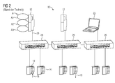
- FIG. 2 shows an automation system 10 according to the prior art in a further embodiment.
- two computing devices 12 and an input device 22 are provided.
- the automation system comprises six peripheral devices 14.
- the peripheral devices 14 and network devices 26 are connected to the computing devices 12 and the input device 22, respectively.
- a uniform data bus 28 is used, which may be designed, for example, as an Ethernet connection.
- Peripheral devices 14 are permanently assigned to a computing device 12. Again, the automation task A and all subtasks A1, A2 and A3 is calculated with a computing device 12.
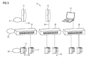
- FIG. 3 shows an embodiment of the automation system 10 according to the invention in a schematic representation.
- the physical topology of the automation system 10 is the same as that in FIG. 2 is shown. However, the logical topology differs from that associated with FIG. 2 has been described.
- the strict assignment of the peripheral devices 14 to the computing devices 12 is resolved.
- the automation devices are all equal partners in the automation system 10.
- the automation task A is divided here into the subtasks A1, A2, and A3.
- the distribution of subtasks A1, A2, A3 is the task of automation engineering takes place offline engineering tool on the basis of a list, which represents the existing in reality automation devices of the automation system 10. This distribution of subtasks A1, A2, A3 can be done, for example, by an operator input of the input device 22.
- the dynamic distribution of the individual subtasks A1, A2, A3 to the existing automation devices takes place in two steps. The first steps are assigned to the subtasks offline in automation devices and in the second step, the subtasks A1, A2, A3 are downloaded online and brought to completion.
- the first category of subtasks A1, A2, A3 are device tasks. These are assigned to the automation devices, in particular the peripheral devices 14, based on the physical wiring in the automation system.
- the second category of subtasks A1, A2, A3 comprises computational sub-tasks. These are assigned to the automation devices as a function of the already distributed device tasks. For this purpose, the automation devices, in particular the peripheral devices 14, send out corresponding data with symbols, by means of which their position in the automation system 10 can be determined.
- the automation device can be assigned a computing sub-task that has the least overall distance to all necessary automation devices. Subsequently, it is checked whether the selected automation device can provide the necessary computing power.
- the program code of the subtasks is dynamically executed on automation devices by downloading the program code.
- a description is loaded in addition to the program code, which contain for the execution of relevant parameters, such as a priority and a time behavior.
- the peripheral devices 14 preferably device tasks are brought to expiration. This can be done on the peripheral devices 14 corresponding subtasks to the expiration, which require low processing power.
- the peripheral devices 14 carry out the subtask A3, which includes the "measuring".
- the flow in an automation system with at least one peripheral device 14 can be determined. In this case, the flow can be determined with a plurality of peripheral devices 14. It is also conceivable that the flow is determined at several times with a peripheral device 14.
- subtask A2 the "mean” is determined with the network device 26. It is also conceivable that the mean value is determined with a peripheral device 14. The determined mean value is transmitted to the computing device 12, on which the subtask A1 "control" is performed. Thus, with the computing device 12, a corresponding manipulated variable can be determined, which is transmitted as the peripheral devices 14, by means of which the flow in the automation system is controlled.
Landscapes
- Engineering & Computer Science (AREA)
- Manufacturing & Machinery (AREA)
- Physics & Mathematics (AREA)
- General Physics & Mathematics (AREA)
- Automation & Control Theory (AREA)
- Human Computer Interaction (AREA)
- General Engineering & Computer Science (AREA)
- Quality & Reliability (AREA)
- Programmable Controllers (AREA)
Abstract
Description
Die vorliegende Erfindung betrifft ein Verfahren zum Betreiben eines Automatisierungssystems. Überdies betrifft die vorliegende Erfindung ein Automatisierungssystem.The present invention relates to a method for operating an automation system. Moreover, the present invention relates to an automation system.
Automatisierungssysteme umfassen eine Mehrzahl von Automatisierungsgeräten, die sich im Wesentlichen in zwei Gruppen einteilen lassen. Zum einen umfasst das Automatisierungssystem Recheneinrichtungen, die einen Prozessor bzw. eine CPU aufweisen und entsprechende Berechnungen durchführen können. Zum anderen umfassen Automatisierungssysteme üblicherweise Peripherieeinrichtungen, die als Ein-/Ausgabemodule eine physikalische Verbindung zwischen dem zu automatisierenden technischen Prozess und dem automatisiert technischen System darstellen. Die Peripherieeinrichtungen leiten die mit den entsprechenden Sensoren gemessenen physikalischen Größen, wie beispielsweise den Druck, die Temperatur oder die Position, des technischen Prozesses als analoge oder digitale Daten in Form von Kommunikationstelegrammen über Feldbusse an die Recheneinrichtungen weiter, welche die eigentliche Verarbeitung der Daten vornehmen.Automation systems comprise a plurality of automation devices, which can essentially be divided into two groups. On the one hand, the automation system comprises computing devices which have a processor or a CPU and can perform corresponding calculations. On the other hand, automation systems usually include peripheral devices which, as input / output modules, represent a physical connection between the technical process to be automated and the automated technical system. The peripheral devices forward the measured with the corresponding sensors physical quantities, such as the pressure, temperature or position of the technical process as analog or digital data in the form of communication messages via field buses to the computing devices that make the actual processing of the data.
Die Organisation und damit die Zuordnung der Peripherieeinrichtungen zu den Recheneinrichtungen ist streng hierarchisch gegliedert, sodass eine N:1 Beziehung zwischen den Peripherieeinrichtungen und den Recheneinrichtungen besteht. Jede Peripherieeinrichtung ist an eine bestimmte Recheneinrichtung angeschlossen, sodass auch nur diese die Daten der Peripherieeinrichtung verarbeiten kann. Dabei erfolgt die Kommunikation über Bussysteme auf dieser Feldebene, die deshalb auch als Feldbus bezeichnet werden. Die Kommunikation der Recheneinrichtungen untereinander sowie die Kommunikation mit Eingabeeinrichtungen oder Wartungsgeräten erfolgt mithilfe eines anderen Bussystems auf der Automatisierungsebene.The organization and thus the assignment of the peripheral devices to the computing devices is strictly hierarchical, so that there is an N: 1 relationship between the peripheral devices and the computing devices. Each peripheral device is connected to a specific computing device, so that only these can process the data of the peripheral device. In this case, the communication takes place via bus systems at this field level, which are therefore also referred to as fieldbus. The communication of the computing devices with each other as well as the communication with input devices or maintenance devices takes place with the aid of another bus system on the automation level.
Nicht zuletzt aufgrund unterschiedlicher anderer Anforderungen an die Bussysteme auf Feld- und Automatisierungsebene ist die Aufteilung in zwei Bussysteme historisch gewachsen. Zu diesen Anforderungen zählt unter anderem ein deterministisches Zeitverhalten bei der Datenübertragung, um die Daten nicht nur in ihrem Wert, sondern auch in ihrem Zeitverhalten einschätzen zu können. Beim Feldbus sind früher vorwiegend proprietäre Schnittstellen und Protokolle zum Einsatz gekommen, aber inzwischen setzt sich nahezu überall der Standard Ethernet als physikalische Schnittstelle durch. Die Protokolle können aber noch unterschiedlich sein, wobei einige Bus-systeme, wie beispielsweise Profinet, auch das übliche TCP/IP Protokoll unterstützen.The division into two bus systems has grown historically not least due to the different requirements of the bus systems at the field and automation level. These requirements include, among other things, a deterministic time response during data transmission in order to be able to estimate the data not only in their value but also in their time behavior. In the past, the fieldbus was mainly used for proprietary interfaces and protocols, but meanwhile almost everywhere the standard Ethernet prevails as a physical interface. However, the protocols may still be different, with some bus systems, such as Profinet, also supporting the usual TCP / IP protocol.
Die eindeutige Zuordnung der Peripherieeinrichtungen zu den Recheneinrichtungen hat zur Folge, dass alle Programme, die auf eines dieser Peripherieeinrichtungen bzw. auf dessen Daten zugreifen, zwingend auf der zugeordneten Recheneinrichtung ablaufen müssen. Die Recheneinrichtung kann zwar die Daten der Peripherieeinrichtung anderen Recheneinrichtungen weitergeben, aber über diesen Weg ist keine deterministische Bearbeitung möglich. Wenn das Programm erweitert wird, kann die Recheneinrichtung möglicherweise nicht ausreichend Rechenleistung bereitstellen, sodass eine weitere Recheneinrichtung in dem Automatisierungssystem bereitgestellt werden muss. Dennoch ist eine einfache Verlagerung von Programmteilen nicht möglich, schon gar nicht im laufenden Betrieb des Automatisierungssystems, da die eine Recheneinrichtung zugeordneten Peripherieeinrichtungen ebenfalls verschoben werden müssten. Dies mag im Stillstand der Automatisierungsanlage theoretisch möglich sein, aber nicht, wenn an einer Peripherieeinrichtung Daten für verschiedene Programmteile anliegen, die nicht alle auf die zusätzliche Recheneinrichtung verlagert werden sollen. Durch die eindeutige Zuordnung zu einer Recheneinrichtung kann eine Peripherieeinrichtung seine Daten nicht an verschiedene Recheneinrichtungen schicken. Des Weiteren bieten die Programmierumgebungen keine Hilfe, ob ein zusätzlicher Programmteil noch in eine Recheneinrichtung geladen werden kann, ohne diese ihre Leistungsfähigkeit überschreitet. Diese Tatsache kann zu Programmfehlern führen, wobei die Recheneinrichtung das Programm in einen "sichersten Zustand" überführt, was gegebenenfalls zu einem Stopp der Automatisierungsanlage führen kann.The unambiguous assignment of the peripheral devices to the computing devices has the consequence that all programs that access one of these peripheral devices or its data must necessarily run on the associated computing device. Although the computing device can pass on the data of the peripheral device other computing devices, but no deterministic processing is possible via this path. As the program expands, the computing device may not be able to provide sufficient computational power so that another computing device must be provided in the automation system. Nevertheless, a simple shift of program parts is not possible, especially not during operation of the automation system, since the peripherals associated with a computing device would also have to be moved. This may be theoretically possible at standstill of the automation system, but not if there are data for different program parts at a peripheral device, which should not all be relocated to the additional computing device. Due to the unique assignment to a computing device, a peripheral device can not send its data to different computing devices. Furthermore, the programming environments offer no help, whether one additional program part can still be loaded into a computing device without this exceeds their capacity. This fact can lead to program errors, wherein the computing device, the program in a "safest state" transferred, which may possibly lead to a stop of the automation system.
Die Hauptursache für die Unflexibilität einer Automatisierungsanlage ist die logische Topologie, die sich aus der Definition der Schnittstellen ergibt. So ist die zuvor beschriebene physikalische Topologie bekannt, bei der eine eindeutige Zuordnung einer Peripherieeinrichtung zu einer Recheneinrichtung vorgesehen ist. Darüber hinaus sind neue physikalische Topologien bekannt, die durch die Verwendung von Ethernet als physikalische Feldbus-Schnittstelle möglich wurde. Dabei wurden wiederum historische Hilfskonstrukte definiert, um dem oben beschriebenen Problem entgegenzuwirken. Damit kann jedoch keine ganzheitliche Lösung geschaffen werden, da die Gegebenheit der Zuordnung von Peripherieeinrichtungen zu Recheneinrichtungen bestehen bleibt.The main reason for the inflexibility of an automation system is the logical topology that results from the definition of the interfaces. Thus, the physical topology described above is known in which an unambiguous assignment of a peripheral device to a computing device is provided. In addition, new physical topologies are becoming known, made possible by the use of Ethernet as a physical fieldbus interface. Again, historical auxiliary constructs were defined to counteract the problem described above. However, this can not be a holistic solution created because the givenness of the assignment of peripheral devices remains to computing devices.
Es ist daher Aufgabe der vorliegenden Erfindung einen Weg aufzuzeigen, wie ein Automatisierungssystem einfacher und effizienter betrieben werden kann.It is therefore an object of the present invention to show a way in which an automation system can be operated more simply and efficiently.
Diese Aufgabe wird durch ein Verfahren mit den Merkmalen des Patentanspruchs 1 und durch ein Automatisierungssystem mit den Merkmalen des Patentanspruchs 10 gelöst. Vorteilhafte Weiterbildungen der vorliegenden Erfindung sind in den Unteransprüchen angegeben.This object is achieved by a method having the features of patent claim 1 and by an automation system having the features of
Das erfindungsgemäße Verfahren zum Betreiben eines Automatisierungssystems umfasst das Bereitstellen jeweils mindestens einer Peripherieeinrichtung, Netzwerkeinrichtung und Recheneinrichtung als Automatisierungsgeräte des Automatisierungssystems, wobei die Peripherieeinrichtung zum Erfassen einer Betriebsgröße einer mit dem Automatisierungssystem gekoppelten Automatisierungsanlage und zum Ansteuern der Automatisierungsanlage mittels einer Stellgröße ausgebildet ist, und wobei die Recheneinrichtung zum Bestimmen der Stellgröße anhand der erfassten Betriebsgröße und anhand einer vorgegebenen Automatisierungsaufgabe ausgebildet ist. Darüber hinaus umfasst das Verfahren das Unterteilen der Automatisierungsaufgabe in zumindest zwei Teilaufgaben und das Zuordnen zumindest einer der Teilaufgaben an die Recheneinrichtung und einer anderen der Teilaufgaben an ein von der Recheneinrichtung verschiedenes Automatisierungsgerät.The inventive method for operating an automation system comprises providing at least one peripheral device, network device and computing device as automation devices of the automation system, wherein the peripheral device for detecting an operating variable of an automation system coupled to the automation system and for controlling the automation system is formed by means of a manipulated variable, and wherein the computing device is designed for determining the manipulated variable based on the detected operating variable and on the basis of a predetermined automation task. In addition, the method comprises subdividing the automation task into at least two sub-tasks and assigning at least one of the subtasks to the computing device and another of the sub-tasks to an automation device different from the computing device.
Das Automatisierungssystem umfasst zumindest eine Peripherieeinrichtung, die einen entsprechenden Sensor umfasst, mit der zumindest eine Betriebsgröße einer Automatisierungsanlage erfasst werden kann. So können beispielsweise entsprechende physikalische Größen, wie beispielsweise der Druck, die Temperatur oder die Position, erfasst werden. Darüber hinaus umfasst die Peripherieeinrichtung einen entsprechenden Aktor, mit dem die Automatisierungsanlage angesteuert werden kann. Des Weiteren umfasst das Automatisierungssystem Netzwerkeinrichtungen, die beispielsweise als Switch ausgebildet sein können, mit denen Daten von den Peripherieeinrichtungen zu den Recheneinrichtungen des Automatisierungssystems übertragen werden können. Mit der zumindest einen Recheneinrichtung können die Stellgrößen für die Peripherieeinrichtungen bestimmt werden. Zu diesem Zweck ist eine entsprechende Automatisierungsaufgabe vorgegeben. Diese Teilaufgabe wird zumindest in zwei Teilaufgaben unterteilt und in verschiedenen Automatisierungsgeräten zugeordnet. Dieser Zuordnung liegt die Erkenntnis zugrunde, dass die Teilaufgaben zusätzlich zu den Recheneinrichtungen auch mit den Netzwerkeinrichtungen und den Peripherieeinrichtungen berechnet werden können. So können Teilaufgaben, die eine geringe Rechenleistung benötigen, mit einer Peripherieeinrichtung oder einer Netzwerkeinrichtung berechnet werden. Damit kann die Rechenleistung, die mit der Recheneinrichtung bereitgestellt wird, reduziert werden.The automation system comprises at least one peripheral device that includes a corresponding sensor with which at least one operating variable of an automation system can be detected. For example, corresponding physical variables, such as the pressure, the temperature or the position, can be detected. In addition, the peripheral device comprises a corresponding actuator with which the automation system can be controlled. Furthermore, the automation system comprises network devices, which may be designed, for example, as a switch with which data can be transmitted from the peripheral devices to the computing devices of the automation system. With the at least one computing device, the manipulated variables for the peripheral devices can be determined. For this purpose, a corresponding automation task is specified. This subtask is subdivided into at least two subtasks and assigned in different automation devices. This assignment is based on the knowledge that the subtasks can also be calculated with the network devices and the peripheral devices in addition to the computing devices. Thus, subtasks that require little computing power can be calculated with a peripheral device or a network device. Thus, the computing power provided with the computing device can be reduced.
Das Automatisierungssystem kann auch mehrere Recheneinrichtungen, Netzwerkeinrichtungen und Peripherieeinrichtungen umfassen. Dabei können die Teilaufgaben beliebig auf die einzelnen Automatisierungsgeräte aufgeteilt werden. Dabei soll die strenge Zuordnung von Peripherieeinrichtungen zu Recheneinrichtungen vollständig aufgelöst werden. Alle Automatisierungsgeräte in dem Automatisierungssystem sind gleichberechtigte Partner im Netzwerk, sodass auch jedes Automatisierungsgerät Rechenleistung zur Verfügung stellen kann. Die einzelnen Automatisierungsgeräte können mit einer entsprechenden Datenleitung, insbesondere Ethernet, miteinander verbunden sein, wobei die physikalische Netzwerktopologie durch die Netzwerkeinrichtungen ermöglicht wird. Im Gegensatz zu den aus dem Stand der Technik bekannten Automatisierungssystemen unterscheidet sich die physikalische Topologie des Automatisierungssystems nicht mehr von der logischen Topologie. Damit sind alle Automatisierungsgeräte untereinander gleichberechtigt und können unter voller Beibehaltung des Determinismus kommunizieren. Die aus dem Stand der Technik bekannte Trennung der Kommunikationsmedien in Feldbusse und übergeordnete Bus-Systeme entfällt komplett.The automation system may also include multiple computing devices, network devices, and peripheral devices. The subtasks can be divided arbitrarily among the individual automation devices. The strict assignment of peripheral devices to computing devices should be completely resolved. All automation devices in the automation system are equal partners in the network, so that each automation device can also provide processing power. The individual automation devices can be connected to one another by means of a corresponding data line, in particular Ethernet, the physical network topology being made possible by the network devices. In contrast to the automation systems known from the prior art, the physical topology of the automation system no longer differs from the logical topology. Thus, all automation devices are equal to each other and can communicate with full retention of determinism. The separation of the communication media into field buses and higher-level bus systems known from the prior art is completely eliminated.
Bevorzugt werden den Automatisierungsgeräten mit dem Zuordnen der Teilaufgaben sowohl ein Programm der jeweiligen Teilaufgabe als auch eine zeitliche Anforderung der jeweiligen Teilaufgabe bereitgestellt. Die Verteilung aller Teilaufgaben für die Automatisierungsaufgabe bzw. die automatisierungstechnische Aufgabenstellung erfolgt offline im Engineering-Werkzeug auf Basis einer Liste, welche in der Realität vorhandenen Automatisierungsgeräte repräsentiert. In der Programmierung im Engineering wird die Automatisierungsaufgabe nicht mehr als Block gesehen, der hardwarespezifisch an eine bestimmte Recheneinrichtung gebunden ist, sondern als Konglomerat von Teilaufgaben, die eine Ausweitung der Selbstbeschreibung aufweisen. Diese Selbstbeschreibung enthält die Implementierung bzw. den Programmcode der Teilaufgabe sowie Attribute zur Beschreibung der Anforderungen. Insbesondere werden die zeitlichen Anforderungen bereitgestellt und/oder Anforderungen, wie schnell und wie häufig der Programmcode laufen muss. Des Weiteren können die Anforderungen eine Information über die Größe des Programmcodes umfassen. Diese Anforderungen können in einer über alle Klassen der Automatisierungsgeräte neutralen Einheit vorliegen.The automation devices are preferably provided with the assignment of the subtasks both a program of the respective subtask and a time requirement of the respective subtask. The distribution of all subtasks for the automation task or the automation task takes place offline in the engineering tool based on a list, which represents existing automation devices in reality. In programming in engineering, the automation task is no longer seen as a block that is hardware-specifically linked to a specific computing device, but rather as a conglomeration of subtasks that expand the self-description. This self-description contains the implementation or the program code of the subtask as well as attributes for describing the requirements. In particular, the timing requirements are provided and / or requirements, such as how fast and how often the program code needs to run. Furthermore, the requirements may be information about the size of the program code. These requirements can be present in a unit neutral over all classes of the automation devices.
Bevorzugt umfassen die Teilaufgaben Geräteteilaufgaben, die den Automatisierungsgeräten zugeordnet werden. Insbesondere werden diese Geräteteilaufgaben den Peripherieeinrichtungen zugeordnet. Diese Geräteteilaufgaben sind Teilaufgaben, die fest an ein Automatisierungsgerät gebunden sind, weil sie die vorliegenden physikalischen Messgrößen in kommunikationstechnisch bearbeitbare Telegramme wandeln bzw. diese Telegramme in physikalische Ausgangsgrößen wandeln. Die Zuordnung der Geräteteilaufgaben an die Automatisierungsgeräte erfolgt auf Basis der physikalischen Verdrahtung in der Automatisierungsanlage, wobei dies beispielsweise teil-automatisch erfolgen kann, wenn ein entsprechender Plan des Automatisierungssystems in maschinenlesbarer Form vorliegt. Damit kann eine einfache Zuordnung der Geräteteilaufgaben auf die Automatisierungsgeräte ermöglicht werden.Preferably, the subtasks include sub-tasks that are assigned to the automation devices. In particular, these device sub-tasks are assigned to the peripheral devices. These sub-tasks are subtasks that are permanently linked to an automation device, because they convert the physical variables available into telegrams that can be processed by communication or convert these telegrams into physical output variables. The assignment of the device sub-tasks to the automation devices takes place on the basis of the physical wiring in the automation system, which, for example, can be partially automatic when a corresponding plan of the automation system is present in machine-readable form. This makes it possible to easily assign the device sub-tasks to the automation devices.
In einer weiteren Ausführungsform umfassen die Teilaufgaben Rechenteilaufgaben, die den Automatisierungsgeräten in Abhängigkeit von den zugeordneten Geräteteilaufgaben zugeordnet werden. In einem zweiten Schritt der Zuordnung werden die Rechenteilaufgaben, die insbesondere eine Berechnung von Daten umfassen, auf die Automatisierungsgeräte verteilt. Dabei wird berücksichtigt, welchem der Automatisierungsgeräte bereits eine Geräteteilaufgabe zugeordnet wurde. Auf diese Weise können die Rechenteilaufgaben besonders effizient in Abhängigkeit von den bereits verteilten Geräteteilaufgaben verteilt werden.In a further embodiment, the subtasks comprise computation sub-tasks, which are assigned to the automation devices as a function of the assigned device sub-tasks. In a second step of the assignment, the computational sub-tasks, which comprise, in particular, a computation of data, are distributed to the programmable controllers. It is taken into account which of the automation devices has already been assigned a device sub-task. In this way, the computation sub-tasks can be distributed particularly efficiently depending on the already distributed device sub-tasks.
Bevorzugt werden die Rechenteilaufgaben in Abhängigkeit von einer Topologie des Automatisierungssystems in Automatisierungsgeräten zugeordnet. Zu diesem Zweck können mit den Automatisierungsgeräten entsprechende Daten ausgesendet werden, die Symbole enthalten. Anhand dieser Symbole sind die Automatisierungsgeräte unabhängig von dem konkreten Netzwerk adressierbar. Bevorzugt werden von den Peripherieeinrichtungen entsprechende Daten mit Symbolen ausgesendet. Anhand der Daten und der darin enthaltenen Symbole kann die Verteilung der Automatisierungsgeräte, insbesondere der Automatisierungsgeräte, denen bereits eine Geräteteilaufgabe zugeordnet wurde, ermittelt werden. In Abhängigkeit von dieser Verteilung können dann die Rechenteilaufgaben auf die Automatisierungsgeräte verteilt werden. Dabei kann auch ein entsprechendes Optimierungskriterium, beispielsweise die Minimierung der Netzlast, berücksichtigt werden. Zu diesem Zweck kann ein Optimierungsprozess verwendet werden, der ausgehend von der Topologie des Automatisierungssystems dem Automatisierungsgerät die Rechenteilaufgabe zuordnet, das den geringsten summarischen Abstand zu allen kommunikationstechnisch notwendigen Automatisierungsgeräten hat.The computation sub-tasks are preferably assigned as a function of a topology of the automation system in automation devices. For this purpose, corresponding data can be transmitted with the automation devices that contain symbols. Based on these symbols, the automation devices can be addressed independently of the specific network. Preferably, data corresponding to the peripheral devices are transmitted with symbols. On the basis of the data and the symbols contained therein, the distribution of the automation devices, in particular of the automation devices to which a device sub-task has already been assigned, can be determined. Depending on this distribution, the computing sub-tasks can then be distributed to the automation devices. In this case, a corresponding optimization criterion, for example the minimization of the network load, can also be taken into account. For this purpose, an optimization process can be used which, starting from the topology of the automation system, assigns to the automation device the computing sub-task which has the least overall distance to all communication-relevant automation devices.
In einer weiteren Ausgestaltung werden die Rechenteilaufgaben in Abhängigkeit von der von dem jeweiligen Automatisierungsgerät bereitstellbaren Rechenleistung und/oder einer für die Berechnung der Rechenteilaufgabe benötigten Zeit zugeordnet. Bei der Zuordnung der Rechenteilaufgaben kann alternativ oder zusätzlich zur Berücksichtigung der Topologie des Automatisierungssystems überprüft werden, ob das Automatisierungsgerät, dem eine Rechenteilaufgabe zugeordnet werden soll, die notwendige Rechenleistung zur Verfügung stellen kann. Ebenso kann überprüft, ob von dem Automatisierungsgerät alle weiteren Attribute, wie z. B. die Zeitanforderung, erfüllt werden kann. Wenn diese Bedingungen erfüllt sind, wird die jeweilige Rechenteilaufgabe dem Automatisierungsgerät zugewiesen und dessen freie Rechenleistung entsprechend vermindert. Falls die Bedingungen nicht erfüllt sind, wird das nächste Automatisierungsgerät gesucht, das im Sinne der Netzwerktopologie den geringsten Abstand hat. Das Automatisierungsgerät, das die notwendige Rechenleistung nicht aufbringen kann, kann aus der Liste der verfügbaren Geräte für die Zuteilung der Teilaufgabe bzw. Automatisierungsaufgabe entfernt werden. Für die Verteilung der nächsten Teilaufgabe bzw. Automatisierungsaufgabe kann dieses Automatisierungsgerät wieder verfügbar sein. In einer Ausgestaltung werden die Teilaufgaben in Abhängigkeit von einer Bedieneingabe einer Bedienperson zugeordnet. Gemäß dem Stand der Technik ist es vorgesehen, dass für eine entsprechende Automatisierungsaufgabe die dafür benötigten Automatisierungsgeräte entsprechend angeordnet und miteinander verbunden werden. Durch die Unterteilung der Automatisierungsaufgabe in Teilaufgaben wird es ermöglicht, dass ein bereits vorhandenes Automatisierungssystem genutzt werden kann und die entsprechenden Teilaufgaben auf die Automatisierungsgeräte verteilt werden. Dies kann vollständig manuell durch den Projekteur bzw. eine Bedienperson erfolgen. Ebenso ist eine geeignete automatisierte Abfrage aller angeschlossenen Geräte denkbar. Somit kann die Entscheidung, ob die Rechenleistung der momentan in dem Automatisierungssystem vorhandenen Automatisierungsgeräte ausreichend ist, offline im Engineering erfolgen. So kann der Projekteuer schon zu diesem Zeitpunkt die Anzahl der für die gesamte Automatisierungsaufgabe notwendigen Automatisierungsgeräte festlegen bzw. im Verlauf der Verteilung anpassen.In a further refinement, the computing sub-tasks are assigned as a function of the computing power that can be provided by the respective automation device and / or a time required for calculating the computing sub-task. When allocating the computational sub-tasks, it is possible, as an alternative or in addition to considering the topology of the automation system, to check whether the automation device to which a computation sub-task should be assigned can provide the necessary computing power. Likewise, it can be checked whether the automation device has any further attributes, such as. As the time requirement can be met. If these conditions are fulfilled, the respective calculation task is assigned to the programmable controller and its free computing power is correspondingly reduced. If the conditions are not met, the next automation device is searched for, which has the least distance in terms of the network topology. The automation device, which can not afford the necessary computing power, can be removed from the list of available devices for the allocation of the subtask or automation task. For the distribution of the next subtask or automation task this automation device can be available again. In one embodiment, the subtasks are assigned as a function of an operator input of an operator. According to the prior art, it is provided that for a corresponding automation task, the automation devices required for this purpose are correspondingly arranged and interconnected. By subdividing the automation task into subtasks, it is possible to use an already existing automation system and to distribute the corresponding subtasks to the automation devices. This can be done completely manually by the project engineer or an operator. Likewise, a suitable automated query of all connected devices is conceivable. Thus, the decision as to whether the computing power of the automation devices currently present in the automation system is sufficient can be made offline in the engineering. At this point in time, the project engineer can set the number of automation devices required for the entire automation task or adjust them during the distribution process.
Bevorzugt werden die Teilaufgaben von einer Inbetriebnahme des Automatisierungssystems zugeordnet. Die dynamische Verteilung der einzelnen Teilaufgaben auf die vorhandenen Automatisierungsgeräte läuft in zwei Schritten ab. Im ersten Schritt werden die Teilaufgaben offline Automatisierungsgeräten zugeordnet und in einem zweiten Schritt auf die Automatisierungsgeräte online heruntergeladen und dort zum Ablauf gebracht. Die Automatisierungsgeräte können einen dynamischen Programmcode zum Ablauf bringen, der auf sie heruntergeladen wird. Dazu wird neben dem Programmcode eine Beschreibung geladen, die für die Ausführung relevante Parameter, wie die Priorität oder das Zeitverhalten, enthält. Der Programmcode selbst kann auf verschiedene Arten auf die Automatisierungsgeräte geladen werden, beispielsweise in Abhängigkeit der Leistungsfähigkeit der Automatisierungsgeräte. So wird entweder direkt Binärcode für das Automatisierungsgerät vom Engineering-System erzeugt oder das Runtime-Geräte kann sich diesen selbst erzeugen (Onboard-Compiler bzw. -Interpreter), sodass Quellcode in der Originalsprache oder einer Zwischensprache geladen wird. Neben den Ablaufparametern sind auch die notwendigen Kommunikationspartner und -verbindungen beschrieben, sodass vor dem Starten der Automatisierungsaufgabe diese eingerichtet werden.Preferably, the subtasks are assigned by a commissioning of the automation system. The dynamic distribution of the individual subtasks on the existing automation devices takes place in two steps. In the first step, the subtasks are assigned offline automation devices and downloaded in a second step on the automation devices online and brought to the process there. The automation devices can run a dynamic program code that is downloaded to them. For this purpose, a description is loaded in addition to the program code, which contains parameters relevant to the execution, such as the priority or the time response. The program code itself can be loaded onto the automation devices in various ways, for example as a function of the performance of the automation devices. Thus, either directly binary code for the programmable controller is generated by the engineering system or the runtime device can do this generate it yourself (onboard compiler or interpreter) so that source code is loaded in the original language or an intermediate language. In addition to the process parameters, the necessary communication partners and connections are described, so that they are set up before starting the automation task.
In einer weiteren Ausgestaltung wird die Betriebsgröße der Automatisierungsanlage mit der Peripherieeinrichtung erfasst und beim Erfassen der Betriebsgröße wird zusätzlich ein Zeitstempel bestimmt. In der Projektierung im Engineering wird keine feste Verbindung von Peripherieeinrichtungen zu Recheneinrichtungen vorgenommen. Dementsprechend können alle Recheneinrichtungen einzelne Daten der Peripherieeinrichtungen lesen bzw. schreiben. Da diese Art der Netzwerktopologie nicht zwingend deterministisch arbeitet, wird die zeitliche Korrektheit der Daten über Zeitstempel hergestellt, die die Peripherieeinrichtungen selbst vergeben. Des Weiteren sind die Uhren aller Automatisierungsgeräte in dem Automatisierungssystem in einer dafür notwendigen Auflösung miteinander synchronisiert.In a further embodiment, the operating size of the automation system is detected by the peripheral device and when detecting the operating variable, a time stamp is additionally determined. In project engineering, no fixed connection is made between peripheral devices and computing devices. Accordingly, all computing devices can read or write individual data of the peripheral devices. Since this type of network topology does not necessarily work deterministically, the temporal correctness of the data is established via timestamps, which the peripherals allocate themselves. Furthermore, the clocks of all automation devices in the automation system are synchronized with each other in a necessary resolution.
Das zuvor beschriebene Verfahren kann auch verwendet werden, wenn eine schon laufende Automatisierungsanlage erweitert werden soll. Dazu muss die Automatisierungsanlage nicht gestoppt werden, sondern das Engineering kann die neuen Peripherieeinrichtungen und Recheneinrichtung zunächst offline verteilen und damit ermitteln, ob im gesamten Automatisierungssystem noch genügend freie Rechenleistungen vorhanden sind. Falls dies nicht der Fall ist, kann es eine Abschätzung abgeben, wie leistungsstark das notwendige Automatisierungsgerät mindestens sein sollte. Für die Verteilung neuer Automatisierungsaufgaben bzw. Teilaufgaben bedarf es möglicherweise neuer Peripherieeinrichtungen im Automatisierungssystem. Das Ergänzen des Automatisierungssystems um weitere Peripherieeinrichtungen kann auch im laufenden Betrieb des Automatisierungssystems erfolgen, da zwischen den Peripherieeinrichtungen und den Recheneinrichtungen keine direkte Abhängigkeit besteht.The method described above can also be used if an already running automation system is to be extended. For this purpose, the automation system does not have to be stopped, but the engineering can initially distribute the new peripheral devices and computing device offline and thus determine whether sufficient free computing power is still available in the entire automation system. If this is not the case, it can give an estimate of how powerful the necessary automation device should at least be. The distribution of new automation tasks or subtasks may require new peripheral devices in the automation system. The addition of additional peripheral devices to the automation system can also take place during operation of the automation system, as between the peripheral devices and the computing devices no direct dependence.
Das Verfahren zum Betreiben eines Automatisierungssystems lässt auch intelligente Automatisierungsgeräte zu, die beispielsweise ihre Teilaufgaben bereits integriert haben, und diese nur noch parametrieren, z. B. durch die Vergabe der Symbolnamen. Es kann beispielsweise eine Peripherieeinrichtung verwendet werden, die einen Sensor umfasst, der als Teilaufgabe einen Mittelwert von mehreren Messwerten berechnen kann. Ebenso kann ein Automatisierungsgerät auch integrierte Rechenteilaufgaben in Form einer Bibliothek aufweisen, sodass auch hierbei im Rahmen der Verteilung nicht der Programmcode der Teilaufgabe, sondern nur noch ihre Parameter übertragen werden müssen.The method for operating an automation system also allows intelligent automation devices that have already integrated their subtasks, for example, and only parameterize them, for. B. by assigning the symbol names. For example, a peripheral device may be used, which comprises a sensor which, as a partial task, can calculate an average of a plurality of measured values. Likewise, an automation device can also have integrated compute sub-tasks in the form of a library, so that in this case as part of the distribution not the program code of the subtask, but only their parameters must be transmitted.
Das erfindungsgemäße Automatisierungssystem, das jeweils mindestens eine Peripherieeinrichtung, Netzwerkeinrichtung und Recheneinrichtung als Automatisierungsgeräte umfasst, wobei die Peripherieeinrichtung zum Erfassen einer Betriebsgröße einer mit dem Automatisierungssystem gekoppelten Automatisierungsanlage und zum Ansteuern der Automatisierungsanlage mittels einer Stellgröße ausgebildet ist, und wobei die Recheneinrichtung zum Bestimmen der Stellgröße anhand der erfassten Betriebsgröße und anhand der vorgegebenen Automatisierungsaufgabe ausgebildet ist, weist zusätzlich eine Eingabeeinrichtung auf, die zum Unterteilen der Automatisierungsaufgabe in zumindest zwei Teilaufgaben und zum Zuordnen zumindest einer der Teilaufgaben an die Recheneinrichtung und einer anderen der Teilaufgaben an ein von der Recheneinrichtung verschiedenes Automatisierungsgerät ausgebildet ist. Die zuvor im Zusammenhang mit dem erfindungsgemäßen Verfahren beschriebenen Vorteilen und Weiterbildungen können in gleicher Weise auf das erfindungsgemäße Automatisierungssystem übertragen werden.The automation system according to the invention, each comprising at least one peripheral device, network device and computing device as automation devices, wherein the peripheral device is designed to detect an operating variable of an automation system coupled to the automation system and to control the automation system by means of a manipulated variable, and wherein the computing means for determining the manipulated variable based the detected operating variable and based on the given automation task, additionally has an input device, which is designed to subdivide the automation task in at least two subtasks and assigning at least one of the subtasks to the computing device and another of the subtasks to an automation device different from the computing device , The advantages and further developments described above in connection with the method according to the invention can be transferred in the same way to the automation system according to the invention.
Mit dem erfindungsgemäßen Verfahren und dem erfindungsgemäßen Automatisierungssystem kann durch das neue Vorgehen Im Engineering im Allgemeinen und in der Projektierung sowie in der Programmierung im Speziellen einer Automatisierungsaufgabe sowohl die zeitliche als auch die personelle Trennung der dazu notwendigen Einzelschritte ermöglicht werden. Daher muss der Experte für die eigentliche Automatisierungsaufgabe nicht auch ein Experte für deren Umsetzung auf die physikalischen Geräte sein. Zudem kann das Engineering-Werkzeug offline die Auslastung eines Automatisierungsgeräts ermitteln und so dessen Überlastung verhindern, indem es beispielsweise verhindert, dass zusätzliche Teilaufgaben auf das Automatisierungsgerät geladen werden. Das Engineering-Werkzeug kann umgekehrt auch das zur Aufgabe passende Gerät vorschlagen, da es den Rechenaufwand abschätzen kann. Das Automatisierungssystem erlaubt die Verlagerung einer Rechenteilaufgabe von einem Automatisierungsgerät auf ein anderes, ohne von den Restriktionen der direkten Zuordnung und Peripherieeinrichtungen zu Recheneinrichtung betroffen zu sein. Die Verteilung kann neben der freien Rechenleistung auch weitere nicht funktionale Kriterien berücksichtigen, wie beispielsweise die Hochverfügbarkeit oder Fehlersicherheit. Diese wird für eine bestimmte Teilaufgabe festgelegt und die dynamische Verteilung wird diese Aufgabe nur auf Automatisierungsgeräte platzieren, die diese Kriterien erfüllen können. Dabei greifen die obigen Mechanismen zur Veränderung von Überlast in gleicher Weise.With the method according to the invention and the automation system according to the invention, the new procedure In Engineering In general and in the project planning as well as in the programming especially of an automation task, both the temporal and the personnel separation of the necessary individual steps are made possible. Therefore, the expert for the actual automation task does not have to be an expert in implementing it on the physical devices. In addition, the engineering tool can offline determine the utilization of an automation device and thus prevent its overloading, for example by preventing additional subtasks from being loaded onto the automation device. Conversely, the engineering tool can also propose the device suitable for the task, since it can estimate the computational effort. The automation system allows the relocation of a computational task from one automation device to another, without being affected by the restrictions of direct assignment and peripheral devices to computing device. In addition to free computing power, the distribution can also take into account other non-functional criteria, such as high availability or fault tolerance. This is set for a specific subtask and the dynamic distribution will place this task only on automation devices that can meet these criteria. In this case, the above mechanisms for changing overload in the same way.
Die vorliegende Erfindung wird nun anhand der beigefügten Zeichnungen näher erläutert. Dabei zeigen:
- FIG 1
- ein Automatisierungssystem gemäß dem Stand der Technik;
- FIG 2
- ein Automatisierungssystem gemäß dem Stand der Technik in einer weiteren Ausführungsform; und
- FIG 3
- ein erfindungsgemäßes Automatisierungssystem.
- FIG. 1
- an automation system according to the prior art;
- FIG. 2
- an automation system according to the prior art in a further embodiment; and
- FIG. 3
- an inventive automation system.
Die nachfolgend näher geschilderten Ausführungsbeispiele stellen bevorzugte Ausführungsformen der vorliegenden Erfindung dar.The embodiments described in more detail below represent preferred embodiments of the present invention.
Jedes der Peripherieeinrichtungen 14 ist an eine bestimmte Recheneinrichtung 12 angeschlossen. Die Kommunikation erfolgt über einen Datenbus 20 auf dieser Feldebene, wobei der Datenbus 20 als Profibus PA oder Profibus DP ausgebildet sein kann. Mit den Recheneinrichtungen 12 können die Daten der Peripherieeinrichtungen 14 verarbeitet werden. So kann anhand der mit den Peripherieeinrichtungen 14 erfassten Betriebsgrößen und anhand einer Automatisierungsaufgabe A mit den Recheneinrichtungen 12 Stellgrößen bestimmt werden, die wiederum an die Peripherieeinrichtungen 14 übertragen werden. Die Automatisierungsaufgabe A kann beispielsweise die Durchflussregelung in einer Automatisierungsanlage betreffen. Dabei umfasst die Automatisierungsaufgabe die Teilaufgaben A1, A2 und A3. Die Teilaufgabe A1 betrifft das "Steuern", die Teilaufgabe A2 betrifft die "Mittelwertbildung" und die Teilaufgabe A3 das "Messen". Vorliegend werden alle Teilaufgaben A1, A2 und A3 der Automatisierungsaufgabe A von einer Recheneinrichtung 12 durchgeführt.Each of the
Des Weiteren umfasst das Automatisierungssystem 10 eine Eingabeeinrichtung 22, mit der beispielsweise die Automatisierungsaufgabe A von einer Bedienperson eingegeben werden kann. Die Kommunikation der Recheneinrichtungen 12 untereinander sowie die Kommunikation mit der Eingabeeinrichtung 22 erfolgt einem weiteren Datenbus 24, der beispielsweise als Profibus oder Profinet ausgebildet sein kann. Bei dem Automatisierungssystem 10 gemäß
Die Automatisierungsaufgabe A ist vorliegend in die Teilaufgaben A1, A2, und A3 unterteilt. Die Verteilung der Teilaufgaben A1, A2, A3 wird die automatisierungstechnische Aufgabenstellung erfolgt offline Engineering-Werkzeug auf Basis einer Liste, welche die in der Realität vorhandenen Automatisierungsgeräte des Automatisierungssystems 10 repräsentiert. Diese Verteilung der Teilaufgaben A1, A2, A3 kann beispielsweise durch eine Bedieneingabe der Eingabeeinrichtung 22 erfolgen. Die dynamische Verteilung der einzelnen Teilaufgaben A1, A2, A3 auf die vorhandenen Automatisierungsgeräte läuft in zwei Schritten ab. Die ersten Schritte werden die Teilaufgaben offline in Automatisierungsgeräten zugeordnet und im zweiten Schritt werden die Teilaufgaben A1, A2, A3 online heruntergeladen und zum Ablauf gebracht.The automation task A is divided here into the subtasks A1, A2, and A3. The distribution of subtasks A1, A2, A3 is the task of automation engineering takes place offline engineering tool on the basis of a list, which represents the existing in reality automation devices of the
Dabei werden zwei Kategorien von Teilaufgaben A1, A2, A3 unterschieden. Die erste Kategorie der Teilaufgaben A1, A2, A3 sind Geräteteilaufgaben. Diese werden den Automatisierungsgeräten, insbesondere den Peripherieeinrichtungen 14, auf Basis der physikalischen Verdrahtung in der Automatisierungsanlage zugeordnet. Die zweite Kategorie der Teilaufgaben A1, A2, A3 umfasst Rechenteilaufgaben. Diese werden den Automatisierungsgeräten in Abhängigkeit von den bereits verteilten Geräteteilaufgaben zugeordnet. Zu diesem Zweck können die Automatisierungsgeräte, insbesondere die Peripherieeinrichtungen 14, entsprechende Daten mit Symbolen aussenden, anhand der ihre Position im Automatisierungssystem 10 bestimmt werden kann. Anhand eines Optimierungsprozesses kann ausgehend von der Topologie des Automatisierungssystems 10 dem Automatisierungsgerät eine Rechenteilaufgabe zugeordnet werden, dass dem geringsten summarischen Abstand zu allen notwendigen Automatisierungsgeräten aufweist. Im Anschluss daran wird überprüft, ob das ausgewählte Automatisierungsgerät die notwendige Rechenleistung bereitstellen kann.There are two categories of subtasks A1, A2, A3. The first category of subtasks A1, A2, A3 are device tasks. These are assigned to the automation devices, in particular the
Nach Verteilung der Teilaufgaben auf die Automatisierungsgeräte wird auf Automatisierungsgeräten der Programmcode der Teilaufgaben dynamisch zum Ablauf gebracht, indem der Programmcode heruntergeladen wird. Dazu wird neben dem Programmcode auch eine Beschreibung geladen, die für die Ausführung relevanter Parameter, wie eine Priorität und ein Zeitverhalten, enthalten. Den Peripherieeinrichtungen 14 werden bevorzugt Geräteteilaufgaben zum Ablauf gebracht. Damit können auf den Peripherieeinrichtungen 14 entsprechende Teilaufgaben zum Ablauf gebracht werden, die eine geringe Rechenleistung benötigen. Im vorliegenden Beispiel wird von den Peripherieeinrichtungen 14 die Teilaufgabe A3 durchgeführt, welche das "Messen" beinhaltet. So kann beispielsweise der Durchfluss in einer Automatisierungsanlage mit zumindest einer Peripherieeinrichtung 14 bestimmt werden. Dabei kann der Durchfluss mit mehreren Peripherieeinrichtungen 14 bestimmt werden. Ebenso ist es denkbar, dass der Durchfluss zu mehreren Zeitpunkten mit einer Peripherieeinrichtung 14 bestimmt wird. Im vorliegenden Beispiel wird der Teilaufgabe A2, der "Mittelwert", mit der Netzwerkeinrichtung 26 bestimmt. Dabei ist es auch denkbar, dass der Mittelwert mit einer Peripherieeinrichtung 14 ermittelt wird. Der bestimmte Mittelwert wird an die Recheneinrichtung 12 übertragen, auf der die Teilaufgabe A1 "Steuern" durchgeführt wird. Somit kann mit der Recheneinrichtung 12 eine entsprechende Stellgröße bestimmt werden, die wie die Peripherieeinrichtungen 14 übertragen wird, mittels welcher der Durchfluss in der Automatisierungsanlage gesteuert wird.After the subtasks have been distributed to the automation devices, the program code of the subtasks is dynamically executed on automation devices by downloading the program code. For this purpose, a description is loaded in addition to the program code, which contain for the execution of relevant parameters, such as a priority and a time behavior. The
- 1010
- Automatisierungssystemautomation system
- 1212
- Recheneinrichtungcomputing device
- 1414
- Peripherieeinrichtungperipheral device
- 1616
- Pfeilarrow
- 1818
- Pfeilarrow
- 2020
- Datenbusbus
- 2222
- Eingabeeinrichtunginput device
- 2424
- Datenbusbus
- 2626
- NetzwerkeinrichtungNetwork Setup
- 2828
- Datenbusbus
- AA
- Automatisierungsaufgabeautomation task
- A1, A2, A3A1, A2, A3
- Teilaufgabensubtasks
Claims (10)
Priority Applications (1)
| Application Number | Priority Date | Filing Date | Title |
|---|---|---|---|
| EP12172971.9A EP2677381A1 (en) | 2012-06-21 | 2012-06-21 | Method for operating an automation system |
Applications Claiming Priority (1)
| Application Number | Priority Date | Filing Date | Title |
|---|---|---|---|
| EP12172971.9A EP2677381A1 (en) | 2012-06-21 | 2012-06-21 | Method for operating an automation system |
Publications (1)
| Publication Number | Publication Date |
|---|---|
| EP2677381A1 true EP2677381A1 (en) | 2013-12-25 |
Family
ID=46724203
Family Applications (1)
| Application Number | Title | Priority Date | Filing Date |
|---|---|---|---|
| EP12172971.9A Withdrawn EP2677381A1 (en) | 2012-06-21 | 2012-06-21 | Method for operating an automation system |
Country Status (1)
| Country | Link |
|---|---|
| EP (1) | EP2677381A1 (en) |
Citations (6)
| Publication number | Priority date | Publication date | Assignee | Title |
|---|---|---|---|---|
| US6104962A (en) * | 1998-03-26 | 2000-08-15 | Rockwell Technologies, Llc | System for and method of allocating processing tasks of a control program configured to control a distributed control system |
| US6205362B1 (en) * | 1997-11-24 | 2001-03-20 | Agilent Technologies, Inc. | Constructing applications in distributed control systems using components having built-in behaviors |
| US20060101465A1 (en) * | 2004-11-09 | 2006-05-11 | Hitachi, Ltd. | Distributed control system |
| DE102005017594A1 (en) * | 2005-04-16 | 2006-10-19 | Abb Patent Gmbh | Decentralized automation system, has programming software with tool distributing automation function to filed devices and tool producing and transmitting communication relations between field devices |
| EP1916578A1 (en) * | 2006-10-24 | 2008-04-30 | Triphase NV | A system for real-time process control |
| WO2010130503A1 (en) * | 2009-05-12 | 2010-11-18 | Siemens Aktiengesellschaft | Method and device for placing units for executing an application in a distributed system |
-
2012
- 2012-06-21 EP EP12172971.9A patent/EP2677381A1/en not_active Withdrawn
Patent Citations (6)
| Publication number | Priority date | Publication date | Assignee | Title |
|---|---|---|---|---|
| US6205362B1 (en) * | 1997-11-24 | 2001-03-20 | Agilent Technologies, Inc. | Constructing applications in distributed control systems using components having built-in behaviors |
| US6104962A (en) * | 1998-03-26 | 2000-08-15 | Rockwell Technologies, Llc | System for and method of allocating processing tasks of a control program configured to control a distributed control system |
| US20060101465A1 (en) * | 2004-11-09 | 2006-05-11 | Hitachi, Ltd. | Distributed control system |
| DE102005017594A1 (en) * | 2005-04-16 | 2006-10-19 | Abb Patent Gmbh | Decentralized automation system, has programming software with tool distributing automation function to filed devices and tool producing and transmitting communication relations between field devices |
| EP1916578A1 (en) * | 2006-10-24 | 2008-04-30 | Triphase NV | A system for real-time process control |
| WO2010130503A1 (en) * | 2009-05-12 | 2010-11-18 | Siemens Aktiengesellschaft | Method and device for placing units for executing an application in a distributed system |
Similar Documents
| Publication | Publication Date | Title |
|---|---|---|
| EP2422243B1 (en) | Safety controller for an automated plant and method for creating an application program for a safety controller | |
| DE102008055660B4 (en) | Method and device for accessing a functional module of an automation system | |
| DE102010029952A1 (en) | Method for integrating at least one field device in a network of automation technology | |
| DE102007026678A1 (en) | Method for exchanging a defective field device for a new field device in a system communicating via a digital field bus, in particular an automation system | |
| EP2520991B1 (en) | Method for controlled intervention into the behaviour of a sub-module | |
| EP3444682A1 (en) | Method for the computer-assisted coupling of a processing module into a modular technical system and modular technical system | |
| EP2732347B1 (en) | Method and system for the dynamic distribution of program functions in distributed control systems | |
| EP3039494B1 (en) | Automation system | |
| WO2018036708A1 (en) | Gateway and method for connecting a data source system to an it system | |
| DE10326542B4 (en) | Operating method and control program for a central unit of an automation system and central unit of an automation system and automation system itself | |
| EP3082002B1 (en) | Safety control and method for controlling an automated system | |
| EP3088976B1 (en) | Method for operating an automation device and automation device | |
| EP3977301A1 (en) | Runtime server for simultaneously executing multiple runtime systems of an automation installation | |
| EP3252549B1 (en) | Method for operating an automation device and automation device | |
| EP3268822B1 (en) | Projecting device and method for configuring and/or parameterising automation components of an automation system | |
| DE102010040055A1 (en) | System for communication of several clients with several field devices in automation technology | |
| EP1643679A1 (en) | Configuration of modules in automation systems | |
| EP2216696B1 (en) | Method and communication system for configuring a communication module containing a logic module | |
| EP3770704A1 (en) | Cloud-based decentralized automation system | |
| DE10242004B4 (en) | automation equipment | |
| WO2019228910A1 (en) | Programmable logic controller and operating method for a programmable logic controller and computer program product | |
| EP2557464A1 (en) | Method for operating an automation system | |
| EP2677381A1 (en) | Method for operating an automation system | |
| EP3553608A1 (en) | Automation system and method for operating an automation system | |
| DE102019206128A1 (en) | Method of operating a programmable logic controller |
Legal Events
| Date | Code | Title | Description |
|---|---|---|---|
| PUAI | Public reference made under article 153(3) epc to a published international application that has entered the european phase |
Free format text: ORIGINAL CODE: 0009012 |
|
| AK | Designated contracting states |
Kind code of ref document: A1 Designated state(s): AL AT BE BG CH CY CZ DE DK EE ES FI FR GB GR HR HU IE IS IT LI LT LU LV MC MK MT NL NO PL PT RO RS SE SI SK SM TR |
|
| AX | Request for extension of the european patent |
Extension state: BA ME |
|
| STAA | Information on the status of an ep patent application or granted ep patent |
Free format text: STATUS: THE APPLICATION IS DEEMED TO BE WITHDRAWN |
|
| 18D | Application deemed to be withdrawn |
Effective date: 20140626 |