EP3082002B1 - Safety control and method for controlling an automated system - Google Patents
Safety control and method for controlling an automated system Download PDFInfo
- Publication number
- EP3082002B1 EP3082002B1 EP16169017.7A EP16169017A EP3082002B1 EP 3082002 B1 EP3082002 B1 EP 3082002B1 EP 16169017 A EP16169017 A EP 16169017A EP 3082002 B1 EP3082002 B1 EP 3082002B1
- Authority
- EP
- European Patent Office
- Prior art keywords
- data
- project data
- project
- safety
- memory
- Prior art date
- Legal status (The legal status is an assumption and is not a legal conclusion. Google has not performed a legal analysis and makes no representation as to the accuracy of the status listed.)
- Active
Links
- 238000000034 method Methods 0.000 title claims description 39
- 230000015654 memory Effects 0.000 claims description 193
- 238000012545 processing Methods 0.000 claims description 83
- 238000009826 distribution Methods 0.000 claims description 45
- 230000006870 function Effects 0.000 claims description 38
- 238000004590 computer program Methods 0.000 claims description 4
- 238000009434 installation Methods 0.000 claims 4
- 238000003860 storage Methods 0.000 description 21
- 230000008569 process Effects 0.000 description 18
- 230000008901 benefit Effects 0.000 description 10
- 238000013459 approach Methods 0.000 description 9
- 230000004044 response Effects 0.000 description 8
- 230000000694 effects Effects 0.000 description 7
- 230000001681 protective effect Effects 0.000 description 5
- 238000012546 transfer Methods 0.000 description 5
- 238000013507 mapping Methods 0.000 description 4
- 238000012360 testing method Methods 0.000 description 4
- 230000005540 biological transmission Effects 0.000 description 3
- 230000002950 deficient Effects 0.000 description 3
- 230000009467 reduction Effects 0.000 description 3
- 230000009471 action Effects 0.000 description 2
- 230000008859 change Effects 0.000 description 2
- 238000006243 chemical reaction Methods 0.000 description 2
- 238000013500 data storage Methods 0.000 description 2
- 230000006735 deficit Effects 0.000 description 2
- 230000007257 malfunction Effects 0.000 description 2
- 238000004806 packaging method and process Methods 0.000 description 2
- 238000004886 process control Methods 0.000 description 2
- 230000001360 synchronised effect Effects 0.000 description 2
- 238000013475 authorization Methods 0.000 description 1
- 238000007630 basic procedure Methods 0.000 description 1
- 230000007175 bidirectional communication Effects 0.000 description 1
- 230000006854 communication Effects 0.000 description 1
- 238000004891 communication Methods 0.000 description 1
- 238000001816 cooling Methods 0.000 description 1
- 238000013523 data management Methods 0.000 description 1
- 238000011161 development Methods 0.000 description 1
- 238000003745 diagnosis Methods 0.000 description 1
- 231100001261 hazardous Toxicity 0.000 description 1
- 238000003754 machining Methods 0.000 description 1
- 238000012423 maintenance Methods 0.000 description 1
- 238000004519 manufacturing process Methods 0.000 description 1
- 238000012806 monitoring device Methods 0.000 description 1
- 238000012544 monitoring process Methods 0.000 description 1
- 238000005457 optimization Methods 0.000 description 1
- 238000013439 planning Methods 0.000 description 1
- 230000035484 reaction time Effects 0.000 description 1
- 230000009897 systematic effect Effects 0.000 description 1
- 230000007704 transition Effects 0.000 description 1
- 238000012800 visualization Methods 0.000 description 1
Images


Classifications
-
- G—PHYSICS
- G05—CONTROLLING; REGULATING
- G05B—CONTROL OR REGULATING SYSTEMS IN GENERAL; FUNCTIONAL ELEMENTS OF SUCH SYSTEMS; MONITORING OR TESTING ARRANGEMENTS FOR SUCH SYSTEMS OR ELEMENTS
- G05B19/00—Programme-control systems
- G05B19/02—Programme-control systems electric
- G05B19/418—Total factory control, i.e. centrally controlling a plurality of machines, e.g. direct or distributed numerical control [DNC], flexible manufacturing systems [FMS], integrated manufacturing systems [IMS], computer integrated manufacturing [CIM]
- G05B19/41865—Total factory control, i.e. centrally controlling a plurality of machines, e.g. direct or distributed numerical control [DNC], flexible manufacturing systems [FMS], integrated manufacturing systems [IMS], computer integrated manufacturing [CIM] characterised by job scheduling, process planning, material flow
-
- G—PHYSICS
- G05—CONTROLLING; REGULATING
- G05B—CONTROL OR REGULATING SYSTEMS IN GENERAL; FUNCTIONAL ELEMENTS OF SUCH SYSTEMS; MONITORING OR TESTING ARRANGEMENTS FOR SUCH SYSTEMS OR ELEMENTS
- G05B2219/00—Program-control systems
- G05B2219/30—Nc systems
- G05B2219/32—Operator till task planning
- G05B2219/32283—Machine scheduling, several machines, several jobs
-
- G—PHYSICS
- G05—CONTROLLING; REGULATING
- G05B—CONTROL OR REGULATING SYSTEMS IN GENERAL; FUNCTIONAL ELEMENTS OF SUCH SYSTEMS; MONITORING OR TESTING ARRANGEMENTS FOR SUCH SYSTEMS OR ELEMENTS
- G05B2219/00—Program-control systems
- G05B2219/30—Nc systems
- G05B2219/33—Director till display
- G05B2219/33273—DCS distributed, decentralised controlsystem, multiprocessor
-
- G—PHYSICS
- G05—CONTROLLING; REGULATING
- G05B—CONTROL OR REGULATING SYSTEMS IN GENERAL; FUNCTIONAL ELEMENTS OF SUCH SYSTEMS; MONITORING OR TESTING ARRANGEMENTS FOR SUCH SYSTEMS OR ELEMENTS
- G05B2219/00—Program-control systems
- G05B2219/30—Nc systems
- G05B2219/33—Director till display
- G05B2219/33338—DNC distributed, decentralised nc, concurrent, multiprocessing
-
- Y—GENERAL TAGGING OF NEW TECHNOLOGICAL DEVELOPMENTS; GENERAL TAGGING OF CROSS-SECTIONAL TECHNOLOGIES SPANNING OVER SEVERAL SECTIONS OF THE IPC; TECHNICAL SUBJECTS COVERED BY FORMER USPC CROSS-REFERENCE ART COLLECTIONS [XRACs] AND DIGESTS
- Y02—TECHNOLOGIES OR APPLICATIONS FOR MITIGATION OR ADAPTATION AGAINST CLIMATE CHANGE
- Y02P—CLIMATE CHANGE MITIGATION TECHNOLOGIES IN THE PRODUCTION OR PROCESSING OF GOODS
- Y02P90/00—Enabling technologies with a potential contribution to greenhouse gas [GHG] emissions mitigation
- Y02P90/02—Total factory control, e.g. smart factories, flexible manufacturing systems [FMS] or integrated manufacturing systems [IMS]
Definitions
- the present invention relates to a safety controller and a method for controlling an automated system as a function of project data according to the preambles of claims 1 and 11, the project data representing an application running on the system.
- a safety controller in the sense of the present invention is a device or a device that receives input signals supplied by sensors and generates output signals therefrom by means of logic operations and possibly further signal or data processing steps. The output signals can then be fed to actuators which, depending on the input signals, cause actions or reactions in a controlled system.
- a preferred area of application for such safety controls is the monitoring of emergency stop buttons, two-hand controls, protective doors or light grids in the field of machine safety.
- sensors are used, for example, to secure a machine that poses a risk to people or material goods during operation.
- a signal is generated that is fed to the safety control as an input signal.
- the safety control then switches off the dangerous part of the machine, for example with the help of an actuator.
- a characteristic of a safety controller in contrast to a "normal" controller, is that the safety controller always guarantees a safe state of the hazardous systems or machines even if a malfunction occurs with it or one of the devices connected to it. For this reason, extremely high demands are placed on safety controls for their own fault tolerance, which results in considerable effort in development and manufacture.
- a safety controller is understood to mean a device or a device that meets at least safety category 3 of the mentioned European standard EN 954-1 or whose Safety Integrity Level (SIL) reaches at least level 2 according to the mentioned standard IEC 61508.
- SIL Safety Integrity Level
- a programmable safety control offers the user the possibility of individually defining the logical links and, if necessary, further signal or data processing steps with the help of software, the so-called user program, according to his needs. This results in a Great flexibility compared to previous solutions in which the logical links were created through defined wiring between different safety modules.
- a user program can be created, for example, with the aid of a commercially available personal computer (PC) and using appropriately set up software programs.
- PC personal computer
- the term user program is understood to mean that a user program includes both source code and machine code.
- distributed safety controls In the case of large and thus complex systems according to the state of the art, which are built up from a large number of system hardware components, distributed safety controls are usually used.
- Distributed safety controls consist of a large number of control hardware components. These are control units, sensors and actuators.
- the individual control hardware components are assigned to individual system hardware components.
- distributed safety controls are characterized by great flexibility.
- a safety controller can be built from any number of different control hardware components and can therefore be adapted very flexibly to the conditions of the system to be controlled.
- distributed safety controls are not yet optimal. There is no provision for distributing project data, that is, data that represent an application running on the controlled system, to the individual control hardware components.
- On site in this context means that the project data is processed where the data required for its processing is available. For example, in a control unit that is located in the immediate vicinity of a sensor, whose sensor signal is required as an input signal for determining a control signal for an actuator. Or processing even takes place in the sensor itself.
- US 6,170,044 B1 discloses a system and a method according to the preambles of claims 1 and 11.
- the system includes a plurality of process controls, each of which controls a sub-process in a plant.
- a higher-level controller communicates with the process controllers and generates higher-level data in order to optimize the process flow in the plant.
- At least some of the process controls are redundant, with a first processor module controlling a partial process, while a second processor module remains passive until the first processor module fails and its control tasks are taken over by the second processor module.
- process data in the memory of the second processor module are continuously synchronized with the process data in the memory of the first processor module.
- U.S. 5,699,242 discloses a control system for a factory plant with a plurality of control devices. So-called end control devices, for example in the form of programmable logic controllers (PLC), control individual sub-processes. Groups of end control devices are coordinated by higher-level controls. Several end control devices can use a common memory area in order to carry out functionally identical tasks.
- PLC programmable logic controller
- EP 1 231 526 A1 discloses a control system with a plurality of networked controllers.
- a so-called connection memory stores process data in the Network to be shared.
- the individual controls use uniform variable names to access this shared data.
- the new safety control and the new method are based on the idea of providing a distribution unit in a safety control that is designed to distribute at least part of the project data to data memories contained in control hardware components and thus the distribution of project data to control hardware components that make up the safety control is to enable.
- project data can be specifically saved in individual data memories that are contained in various control hardware components.
- This also enables project data to be saved in so-called intelligent input / output units.
- sensors and actuators that have data processing units, for example microprocessors, and data memories.
- data memories available in a safety controller which would otherwise largely remain unused, can be filled with project data and thus used.
- control units that are present in a safety controller can be equipped with smaller data memories in the future. This reduces the costs for a safety controller.
- the response time of a safety controller is reduced. Project data can be saved there and are therefore available where, for example, required sensor signals are present or control signals for actuators are to be provided. This reduces the data exchange, which ultimately leads to a reduction in the response time. The reduction in data exchange also leads to an increase the availability of the safety controller. Since there is less data to be exchanged, there are also fewer data transmission errors.
- Distributing and thus saving project data in several project data memories also has advantages with regard to the implementation and handling of a safety controller. If, for example, after planning a safety controller in trial operation, it is found that the memory capacity available in the safety controller and formed by all data memories is too small, this can be increased by adding an additional control hardware component that has a data memory. The project data can then be redistributed to the previous and additional data memories. The safety controller can therefore be scaled as required.
- the project data required for the new control hardware component can be provided in a simple manner if a device replacement is necessary. All that is required is to remove the memory card from the defective control hardware component to be removed and insert it into the new control hardware component to be inserted.
- address data, configuration data and program data can be made available without a notebook having to be connected to the new control hardware component for this purpose.
- the project data include program data and / or configuration data and / or parameterization data.
- the program data represent the user program and are generated when the user program is created.
- the configuration data represent individual aspects of the data transmission. This involves, for example, a cycle time, link data that determine which of the control hardware components are connected to one another, or data that represent which sensors or actuators, which inputs or outputs of individual control units are assigned, or to data that determine the type of data to be exchanged between individual control hardware components, for example. It is therefore data that represent the configuration of the safety control that is implemented in a distributed manner.
- the configuration data can be generated when creating the user program. However, they can also be created or changed to a certain extent after the user program has been created.
- the parameterization data represent value ranges for individual variables or functionalities used in the user program.
- At least some of the control hardware components contain a data processing unit, project data specific to the respective data processing unit being stored in that project data memory that is contained in that control hardware component in which the data processing unit is contained.
- a data processing unit can be a unit to which data is supplied as input data for an operation and which outputs output data determined as a result of this operation as a function of the input data.
- a data processing unit can, however, also be understood to mean a unit to which data is supplied in order to pass it on to another unit.
- Safety controls contain data processing units in the most varied of configurations. For example, data-based message switching units are used. For example, these make data generated by their own control unit available to other control units and read data generated by other control units, which are required in the own control unit for further processing. Such data processing units are known as data brokers.
- Event-based message switching units can also be involved. Such message switching units send a signal when a defined condition is met in their own control unit in order to trigger a defined reaction in another control unit or in the system to be controlled. Such message switching units also receive such signals in a corresponding manner. Such message switching units are known as event brokers. In addition, connection units are also used that are required to enable data exchange between individual control hardware components at all. Such data processing units are referred to as data bus interfaces. In addition, a project data memory is also a data processing unit, since the project data memory can not only store project data but also request and forward project data. Depending on how the data processing unit is designed, the respective project data stored for the data processing unit differ.
- an event broker or a data bus interface for example, configuration data and parameterization data are stored.
- project data are also stored for a project data memory, preferably those project data that are processed in the control unit in which the project data memory is contained.
- At least one of the project data memories is designed to forward project data supplied to it to at least one other project data memory or to request project data stored in another project data memory.
- a project data memory which is designed to store, forward and request project data, can also be referred to as a project data server, or project server for short, due to this range of functions.
- the distribution unit is one of the project data memories.
- This measure has the advantage that no additional unit needs to be provided in the safety controller for distributing the project data.
- the project data is distributed from one of the project data memories already present in the safety controller. This enables a cost-effective implementation of the safety control.
- Another advantage is that functionalities that are present in a project data memory and that have been optimized with regard to the processing of project data can be used for distributing the project data.
- the interface of a project data memory is given as an example.
- the project data memory that is used as a distribution unit has the function of a master when distributing the project data.
- the remaining project data memories each take on the function of a slave.
- the project data memory that is used as a distribution unit advantageously has a greater storage capacity than would be required for the operation of that control hardware component in which it is arranged. For the following reason: When the project data is distributed, data is generated that is required for later operation of the safety controller. These can thus be cached in the aforementioned project data memory.
- the project data are usually created using a programming tool that runs on a programming unit. This is usually a structurally separate unit from the safety controller.
- the programming unit comprises, for example, a computer designed as a personal computer.
- the programming unit can be connected via a cable to that control hardware component in which the project data memory is contained, or even to the project data memory itself. This configuration is particularly suitable when the complete project data is to be imported into the safety controller in a single process.
- the project data can be transferred to the project data memory using a mobile storage medium.
- memory cards which can be designed as SD cards (Secure Digital Memory Cards) or CF cards (Compact Flash Cards), or a USB stick (Universal Serial Bus) can be used.
- SD cards Secure Digital Memory Cards
- CF cards Compact Flash Cards
- USB stick Universal Serial Bus
- a conscious user action is advantageously to be carried out for the initialization of the distribution process.
- a specific key combination has to be pressed or a button has to be pressed or a defined input has to be made via a graphic surface.
- the distribution process is advantageously initialized automatically by the programming unit.
- a mobile storage medium has various advantages. It is thus possible to only upload project data to selected control hardware components by specifically connecting the mobile storage medium to these control hardware components. Another advantage is that the mobile storage medium can also be used for backup purposes.
- the machine code stored in a safety controller can be stored on the mobile storage medium and read into the safety controller again if necessary.
- the distribution unit is an external distribution unit which is connected at least temporarily to an interface provided for this purpose in the safety controller.
- the external distribution unit is located in the programming unit on which the programming tool that is used to create the project data runs. This allows the project data to be transferred directly from the programming unit to the safety controller. On the one hand, this is not very complex. On the other hand, this increases the fail-safe safety of the safety controller, since potential sources of error with regard to the transfer of the project data are excluded.
- a further advantage of this embodiment is that after the project data has been completed in a so-called trial operation, in which the functionality of the safety controller and the system to be controlled is tested and in which it is determined that changes to the project data are to be made, these in can be updated easily.
- the project data is transferred from the programming unit to the safety controller, for example, using a cable.
- the programming unit is not permanently connected to the safety controller, but only temporarily. For example, for the period of programming, i.e. for the period in which the project data is generated. Or even only for the period during which the project data is being transferred from the programming unit to the safety controller.
- the programming unit can be understood as part of the safety control, since the project data, in particular the user program for the system to be controlled, are generated with the programming unit.
- control hardware components are control units and / or sensors and / or actuators.
- control units can be used as project data memories, but also the memories present in so-called intelligent sensors and intelligent actuators.
- This enables a particularly flexible distribution of the project data, in particular to the effect that partial processing of the project data can take place directly on site. This helps to improve the response time of the safety controller.
- the project data are divided into a multiplicity of data packets, the individual data packets each being assigned to at least one of the project data memories.
- This measure has the advantage that the project data can be specifically assigned to individual project data memories in accordance with a specific distribution criterion. In this way, a safety controller can be optimized with regard to different parameters by appropriate selection of the distribution criterion.
- a programming unit for creating the project data, the programming unit being designed to generate assignment data, the distribution unit also being designed to distribute the project data to the project data memory as a function of the assignment data.
- the project data can be distributed to the individual project data memories according to a freely definable distribution criterion. At the same time, an error-free and, if necessary, as often reproducible distribution of the project data is guaranteed.
- the assignment data can have the character of a proposal and represent a list of preferences which, for example, the creator of the project data or the operator of the system to be controlled can change. On the other hand, it can also be provided that the assignment data cannot be changed, so that in this case the project data is distributed completely automatically.
- the assignment data can contain, for example, the following information: For each project data memory contained in the safety controller, the data packets to be saved on this or the data packets then saved on it are listed. It is therefore clear which data packet belongs to which control hardware component or which data processing unit.
- the assignment data can also determine the order of the project data memories in which they are used when distributing the Project data are taken into account. Such an order provides that the project data memory that is used as the distribution unit is always taken into account first.
- the assignment data can contain information about which data packets are to be stored in the respective project data memory or are then stored there.
- information can be provided for each control hardware component which specifies the project data memories on which the project data of the respective control hardware component are located.
- each control hardware component or each data processing unit can call up the project data provided for them from the corresponding project data memories in which they are stored. It is also conceivable to only generate part of the assignment data during the distribution process itself. This is useful, for example, for the data, specifying the project data memories on which the project data of the respective control hardware components are located.
- the programming unit is designed to determine the assignment data as a function of at least one data processing parameter.
- the data processing parameter represents a parameter relevant for data processing of a component used in data processing. This can be, for example, the clock frequency of a microprocessor, the data rates of a data broker or an event broker or a data bus interface or the storage capacity of a project data memory. If data processing parameters of the control hardware components or individual units built into them are taken into account when determining the assignment data, then the project data can be distributed from the point of view of optimized data processing. For example, project data that requires high computing power to process can be stored in control hardware components that are equipped with a powerful microprocessor. In addition, depending on their size, data packets can be based on those in the safety controller Data storage are distributed. For example, small data packets can be stored in a targeted manner in data memories with a small storage capacity. This measure is particularly advantageous for a completely automatic distribution of the project data to the project data memory.
- the programming unit is designed to determine the assignment data as a function of at least one function assignment variable.
- the function allocation variable represents for an individual data packet or a group of data packets that project data memory in which this data packet or this group is to be stored.
- the project data memory is defined in that the storage is to take place in that project data memory which is located in that control hardware component, in particular that control unit, in which the project data are processed.
- the function assignment variables are advantageously specified by the programmer of a user program in that he stipulates which scopes of the user program should run on soft control hardware components, for example control units.
- At least part of the project data is stored redundantly in the project data memory.
- the redundant storage of the data packets is achieved by duplicating the respective data packets.
- the duplicated data packets are then distributed independently to the project data memories, with the proviso that the original and the duplicated data packets are each in a different project data memory get saved.
- This measure has the advantage that the availability of the safety control and thus of the controlled system is increased. If, for example, a non-safety-relevant control hardware component fails, the project data that were stored in your project data memory are still available because they are still available in another project data memory. This also makes it easier to replace a defective control hardware component. All you have to do is replace the defective component with a new component.
- the project data required for the new component can, for example, be automatically requested from the respective project data memories on which they are still stored and stored in the project data memory of the new component.
- the redundant storage of the project data also enables individual control tasks to be carried out in parallel.
- At least some of the project data memories are designed to store the project data supplied in each case in a non-volatile manner.
- This measure has the advantage that the project data is still available, for example after a power failure or after the safety controller has been switched off. This increases the availability of the safety controller.
- the safety controller does not need to be re-initialized. For example, memory cards in the form of SD cards or CF cards are used for this, or flash memories are used.
- the progress of the distribution process can preferably be displayed by graphic means during the distribution of the project data to the individual project data stores. In this way, for example, an operator of the system to be controlled can easily find out about the status of the distribution process.
- Each control hardware component preferably contains a project data memory. This enables an optimal distribution of the project data.
- the project data is available wherever it is needed.
- the application running on the system to be controlled can also be referred to as a process, which includes both standard control tasks and safety control tasks.
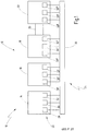
- a system to be controlled is designated in its entirety with the reference number 10.
- the system 10 consists of a large number of system hardware components 12.
- a loading station 14 a processing station 16, a test station 18, a conveyor unit 20 and a packaging and palletizing station 22.
- a safety controller in its entirety denoted by the reference number 24.
- the safety controller 24 contains a large number of control hardware components 26.
- the control hardware components 26 are control units 28, sensors 30 and actuators 32.
- the individual control units 28, sensors 30 and individual actuators 32 are each assigned to one of the system hardware components 12 and are spatially arranged there .
- the control hardware components 12 are connected to one another via a connection unit 34.
- the connection unit 34 is a data bus which is designed, for example, as an Ethernet-based field bus.
- a data bus system is preferably used, which works according to the SafetyNET p ® communication model, which can be traced back to the applicant.
- the processing station 16 With the loading station 14, the processing station 16 is filled with workpieces. These workpieces are processed in the processing station 16. The machined workpieces are then passed on from the machining station 16 to the test station 18, in which it is checked whether the machined workpiece meets the corresponding test criteria. If these test criteria are met, the processing station 16 can be filled again with a new workpiece. The processed workpiece is transferred to the packaging and palletizing station 22 by means of the conveyor unit 20. In this, several processed workpieces are combined into bundles, which are then stacked on a pallet.
- the working areas of the individual stations 14, 16, 18, 22 can be secured, for example, by protective doors that are equipped with safety switches, by means of which a tumbler with locking can be implemented. Alternatively or in addition, light grids or light curtains can also be used.
- the individual stations 14, 16, 18, 22 can be provided with emergency stop buttons with which the respective station can be switched to a safe state by disconnecting it from the power supply. Contactors are controlled accordingly for this.
- the aforementioned protective doors, light grids, light curtains and emergency stop buttons are safety-relevant sensors that are contained in the sensors 30.
- the contactors are safety-relevant actuators that are contained in the actuators 32.
- the sensors 30 can furthermore comprise non-safety-relevant sensors. These are sensors that record operating variables, for example input variables required for drive or position control, such as rotational speeds, angles or speeds.
- the actuators 32 can also include actuators that are not relevant to safety. These can be motors or actuating cylinders, for example.
- a control unit 28 is assigned to each station 14, 16, 18, 22.
- the control units 28 are structurally independent Components trained. This also applies to the sensors 30 and the actuators 32. However, this is not intended to have a restrictive effect. It is also conceivable, for example, to assign a common control unit to two stations.
- the individual system hardware components can be structurally and spatially separated from one another. However, it is also conceivable that some of these components are operatively connected to one another.
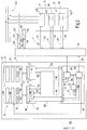
- Fig. 2 the processing station 16 and the control hardware components assigned to it are shown in a more detailed representation. These are the control unit 28 ', the sensors 30' and the actuators 32 ', which are connected to one another by the connection unit 34.
- the control unit 28 ' has a two-channel redundant structure in order to achieve the necessary fail-safe security for controlling safety-critical applications or processes. Representing the two-channel structure are in Fig. 2 two separate processors, namely a first processor 40 and a second processor 42, shown.
- the two processors 40, 42 are connected to one another via a bidirectional communication interface 44 in order to be able to monitor one another and exchange data.
- the two channels of the control unit 28 'and the two processors 40, 42 are preferably constructed diversely, ie different from one another, in order to largely rule out systematic errors.
- Reference numeral 46 denotes an input / output unit which is connected to each of the two processors 40, 42.
- the input / output unit 46 takes Control input signals 48 from the sensors 30 ′ and forwards them in an adapted data format to each of the two processors 40, 42.
- the input / output unit 46 generates control output signals 50 as a function of the processors 40, 42, with which the actuators 32 ′ are controlled.
- the reference number 52 denotes a project data memory in which project data 54 are stored in the form of data packets.
- This is a first data packet 56 which contains first configuration data 58 for a data broker 60.
- the project data memory 52 contains a second data packet 62 with second configuration data 64 for an event broker 66.
- the project data memory 52 contains a third data packet 68 with third configuration data 70 for a data bus interface 72 contains itself.
- the project data memory 52 contains a fifth data packet 76 and a sixth data packet 78.
- These two data packets contain program data which represent the scope of a user program that is processed in the control unit 28 '.
- the project data memory 52 also contains a seventh data packet 80 which contains parameterization data. These parameterization data are required, for example, when processing the project data and define, for example, value ranges for variables or functionalities.
- the actuators 32 'and the sensors 30' are also equipped with project data memories 52 ', 52 ", 52"', 52 "”. This is not intended to have a restrictive effect. Not all control hardware components need to have project data memories. that only project data 54, which are processed in units contained in the control unit 28 ', are stored in the project data memory 52. Project data 54 that are required or processed in another control hardware component can also be stored in the project data memory 52 Data packets from units that are contained in the control unit 28 'are also stored in a project data memory of another control hardware component Fig. 2 The selected division into the individual data packets is not restrictive Have an effect. It is also conceivable to combine different project data, all of which are intended for a data processing unit, for example program data and configuration data, into a data packet.
- the project data memory 52 is designed such that the project data 54 stored in it are stored non-volatile.
- the project data memory 52 is designed, for example, as a flash memory or as an SD card or as a CF card.
- the project data memory 52, the data broker 60, the event broker 66 and the data bus interface 72 are data processing units.
- the data bus interface 72 ensures that a data exchange between the control unit 28 'and the connection unit 34 is synchronized, i.e. takes place in accordance with the protocol of the data bus system used.
- the data bus interface 72 controls both the data broker 60 and the event broker 66.
- Event-based data is exchanged between the control unit 28 'and the connection unit 34 and thus another control hardware component via the event broker 66.
- the project data to be stored in the project data memory 52 are supplied via the event broker 66 during the distribution process.
- project data which it has requested and which are stored in the project data memory 52 can be fed to another control hardware component via the event broker 66.
- a data-based data exchange takes place via the data broker 60 between the control unit 28 'and the connection unit 34 and thus one of the other control hardware components. For example, control input signals required in control unit 28 'are supplied via data broker 60 or control output signals generated in control unit 28' are output.
- the project data 54 are in the form of machine code.
- the fifth data packet 76 is for the first Processor 40 and the sixth data packet 78 for the second processor 42 is determined.
- the fifth data packet 76 comprises a first security code 82 and a standard code 84.
- the first security code 82 comprises those control instructions which are to be processed by the first processor 40 as part of the security tasks to be carried out by the control unit 28 '. These types of control instructions are hereinafter referred to as safety control instructions.
- the standard code 84 comprises those control instructions which are to be processed by the first processor 40 as part of the standard tasks to be performed by the control unit 28 '.
- Standard tasks are tasks that result from the desired "normal" operational sequence of the plant and that have no particular safety-related significance. These types of control instructions are hereinafter referred to as standard control instructions.
- the sixth data packet 78 includes a second security code 86, which includes those control instructions that are to be processed by the second processor 42. These control instructions are hereinafter referred to as safety control instructions.
- a first current safety control instruction 88 and on the other hand a current standard control instruction 90 are processed in the first processor 40.
- a second current safety control instruction 92 is processed essentially at the same time in the second processor 42.
- first non-safety-relevant data 94 are exchanged between the first processor 40 and the input / output unit 46.
- instantaneous values of non-safety-relevant control input signals 48 which are generated by non-safety-relevant sensors 95, are fed to the first processor 40.
- the non-safety-relevant sensors 95 are sensors which, for example, detect input variables required for drive control. This can be, for example, speeds, angles or speeds.
- the non-safety-relevant sensors 95 are designed to be non-fail-safe.
- the input / output unit 46 instantaneous values of non-safety-relevant control output signals 50 are supplied, which non-safety-relevant actuators 97 are supplied to control them.
- the non-safety-relevant actuators 97 can be motors or actuating cylinders, for example.
- the instantaneous values of the non-safety-relevant control output signals 50 are determined as a function of the non-safety-relevant control input signals 48 in accordance with the standard control instructions. In this case, it may be necessary to determine intermediate variables, the instantaneous values of which are fed to a main memory 98 by means of second non-safety-relevant data 96 and are temporarily stored there.
- first safety-relevant data 100 are exchanged between the first processor 40 and the input / output unit 46.
- instantaneous values of safety-relevant control input signals 48 ′ which are generated by safety-relevant sensors 101, are fed to the first processor 40.
- the safety-relevant sensors 101 are, for example, emergency stop buttons, protective doors, speed monitoring devices or other sensors for recording safety-relevant parameters.
- the input / output unit 46 is supplied with instantaneous values of safety-relevant control output signals 50 ', which safety-relevant actuators 103 are supplied to control them.
- the safety-relevant actuators 103 are, for example, redundant safety contactors with working contacts which are arranged in the connection between a power supply 102 and the processing station 16.
- the power supply 102 of the processing station 16 can thus be switched off in two channels, which makes it possible to transfer at least the processing station 16 to a safe state if a corresponding malfunction occurs.
- the instantaneous values of the safety-relevant control output signals 50 ' are determined as a function of the safety-relevant control input signals 48' in accordance with the safety control instructions. It may be necessary to determine safety-relevant intermediate values, the instantaneous values of which are fed to the main memory 98 by means of second safety-relevant data 104 and are temporarily stored there.
- the procedure is in accordance with the first current safety control instruction 88.
- third safety-related data 106 which correspond to the first safety-related data 100
- fourth safety-related data 108 which correspond to the second safety-related data 104
- the reference numeral 110 identifies project data that may be exchanged between individual control hardware components and thus project data memories 52, 52 ', 52 ", 52"', 52 "".
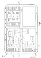
- Fig. 3 are the project data memories 52 contained in the control units 28, the project data memories 52 'contained in the safety-relevant actuators 103, the project data memories 52 "contained in the non-safety-relevant actuators 97, the project data memories 52''' contained in the non-safety-relevant sensors 95 and the project data memories 52 "" contained in the safety-relevant sensors 101.
- the individual project data memories are connected to one another via the connection unit 34.
- the entirety of the project data memories together form a virtual project memory 120 may be present between individual project data memories and the connection unit 34 are omitted.
- a programming unit is designated in its entirety with the reference numeral 122.
- the programming unit 122 essentially consists of a computer 124 which is connected to a display unit 126.
- a computer program 128 is executed on the computer 124.
- the computer program 128 enables the creation of project data 130 which represent an application running on the system to be controlled.
- the project data 130 include program data, configuration data and parameterization data.
- the computer program 128 is often referred to in technical terminology as a programming tool.
- the computer 124 can be designed as a PC and the display unit 126 as a monitor.
- the project data 130 generated with the programming unit 122 and present on the computer 124 are transferred to the project data memories 52, 52 ′, 52 ′′, 52 ′′ ′′, 52 ′′ ′′ of a distributed safety control 24 130 divided into a plurality of data packets 132, the individual data packets 132 each being assigned to one of the project data memories 52, 52 ', 52 ", 52"', 52 "" '.
- the project data more precisely the individual data packets 132, are distributed to the individual project data memories as a function of assignment data 134.
- the assignment data 134 are generated in the programming unit 122.
- the assignment data 134 can be determined, for example, as a function of at least one data processing parameter or as a function of at least one function assignment variable.
- a safety controller 24 can be designed in such a way that a programmer can choose one of these three procedures at will. But it is also conceivable that a safety controller 24 is designed such that only one or two of the procedures for the transfer of the project data 130 are provided.
- a first procedure is indicated by a sequence of arrows 136.
- both the project data 130 and the assignment data 134 are transmitted, for example in a wired manner, from the programming unit 122 via a first interface 138 provided for this purpose to the project data memory 52, which is located in the control unit 28.
- the distribution unit is a project data memory arranged in the safety controller.
- the project data memory 52 arranged in the control unit 28 distributes the data packets 132 according to the assignment data 134 to the individual project data memories 52, 52 ', 52 ", 52"', 52 “” 'contained in the safety controller 24.
- Said project data memory 52 is for this purpose designed to be able to forward project data supplied to it to at least one other project data memory.
- a second procedure is shown by a first arrow sequence 140.
- the project data 130 and the assignment data 134 are first made available on an external distribution unit 142 contained in the computer 124.
- the functionality of the external distribution unit 142 corresponds to the project data memory 52 contained in the control unit 28.
- the project data 130 are then supplied to the connection unit 34 in a wired manner via a second interface 144 provided for this purpose and, according to the assignment data 134, to the individual project data memories contained in the safety controller 24 52, 52 ', 52 ", 52"', 52 “” '.
- the external distribution unit 142 does not have to be permanently connected to the safety controller 24. It is sufficient if this is only connected for the period of data transmission, for example.
- a third procedure is indicated by a second sequence of arrows 146.
- both the project data 130 and the assignment data 134 are transferred to a mobile storage medium 148.
- the mobile storage medium 148 can be, for example, an SD card, a CF card or a USB stick.
- the mobile storage medium 148 is then stored in a Receiving unit 150 introduced.
- the project data 130 are then fed to the project data memory 52 contained in the control unit 28, which then distributes the data packets 132 according to the assignment data 134 to the project data memories 52, 52 ', 52 ", 52"', 52 "contained in the safety controller 24. '' takes over.
- the control unit 28 ′′ contains a first data processing unit 152.
- the project data required by the first data processing unit 152 are stored in the form of a data packet 132 ′ in the project data memory 52, which is contained in the control unit 28 ′′.
- the first data processing unit 152 can thus call up the project data it needs directly from this project data memory.
- the assignment data 134 are determined as a function of at least one function assignment variable.
- the project data 130 are stored in the control hardware component in which they are processed.
- the assignment data 134 are determined as a function of at least one data processing parameter.
- the data processing parameter can be, for example, the clock frequency of one of the two processors 40, 42 or the data rate of the data broker 60 or the event broker 66 or the storage capacity of a project data memory 52, 52 ', 52 ", 52"', 52 "
- the characteristic variable is automatically determined by the distribution unit in that the distribution unit queries the project data memory connected to the connection unit.
- the project data 130 are preferably distributed in such a way that they are stored in control hardware components that have a high data processing capacity.
- the project data 130 essentially arbitrarily, ie distributed without function assignment to the project data memories 52, 52 ', 52 ", 52"', 52 “”'present in a safety controller 24.
- Fig. 3 This is shown as follows:
- the project data required by a second data processing unit 154 are stored in the form of the data packet 132 ′′ in the project data memory 52, which is contained in the control unit 28 '.
- the project data are thus stored in the control unit in which They are also processed of a data packet 132 "" is stored in one of the project data memories 52 ".
- the third data processing unit 156 can then access this project data via the project data memory 52 which is contained in the control unit 28 ′.
- the project data memory 52 which is contained in the control unit 28 '.
- the project data memory 52 which is contained in the control unit 28 ', has the function of a proxy.
- at least some of the project data memories are designed to automatically forward project data to other project data memories and to request project data from other project data memories.
- the project data 130 are stored redundantly in the project data memories 52, 52 ', 52 ", 52''', 52 ''' saved.
- the project data required by a fourth data processing unit 158 are stored in the form of a data packet 132 '''' both on the project data memory 52, which is contained in the control unit 28 ', and on one of the project data memories 52''''.
- the project data of the fourth data processing unit 158 are not stored on the project data memory 52, which is contained in the control unit 28 '''.
- the fourth data processing unit 158 can either access the data packet 132 ''', which is stored on the project data memory 52 contained in the control unit 28', or on the data packet 132 '''' which is stored in one of the project data memories 52 '''' is saved. If, for example, the project data memory 52 '''' on which the data package 132 '''' is stored, or even the complete control hardware component in which this project data memory is contained, fails, the project data required by the fourth data processing unit 158 are still available , in this case on the project data memory 52, which is contained in the control unit 28 '. Project data that are primarily stored in the project data memory that is contained in the control unit in which the project data are processed can also be stored redundantly. This applies, for example, to the project data of the data package 132 '.
- Safety controls can be designed differently.
- a safety control can be used in which the non-safety-relevant sensors, the safety-relevant sensors, the non-safety-relevant actuators, the safety-relevant actuators and the control units are each equipped with project data memories, as described in Fig. 3 is shown.
- safety controls can also be used in which, for example, only the control units are equipped with project data memories.
- safety controls it is also conceivable to use safety controls that have a degree of equipment with project data memories that lies between these two examples.
- the safety-relevant sensors and the safety-relevant actuators are preferably also equipped with data memories.
- both the first interface 138 and the receiving unit 150 can be arranged in a control unit. Both can be arranged individually or together in any control hardware component. It is also conceivable that the interface 138 and / or the recording unit 150 form a structural unit together with one of the project data memories. Furthermore, it can also be provided that more than one of the project data memories built into the safety controller can be used as a distribution unit.
- the selected representation in which only one of the project data memories 52 ', 52 ", 52"', 52 "'', namely the one contained in the top drawing level contains a data packet, should not have any restrictive effect. For reasons For the sake of clarity, data packages have not been shown for the project data memories contained in the drawing levels below.
- a graphical user interface is designated in its entirety with the reference numeral 170. This graphical surface enables a programmer to create the project data 130. Overall, program data, configuration data and parameterization data are created.
- the graphical user interface 170 includes a system software component field 172 which contains a multiplicity of predefined system software components 174 in the form of graphic symbols.
- the user program and thus the program data are created by providing a large number of system software components.
- the graphical user interface 170 contains a first component field 176.
- the system software components to be provided are selected and transferred to the first component field 176, as indicated by an arrow 178.
- the first component field 176 thus contains a multiplicity of provided system software components 180.
- a component part program is created by logically linking the provided system software components 180. For this purpose, logic inputs and logic outputs of these system software components are connected to one another, which is represented by a large number of connections 182.
- new system software components be created, as indicated by the new system software component 184.
- the individual system software components can be so-called elementary components which themselves do not contain any further software components. However, it can also be a matter of so-called group components, which themselves contain further software components.
- An elementary component contains several aspect blocks. Each of these aspect blocks is assigned to one of several different control aspects, each of these control aspects representing an independent sub-aspect of the safety control.
- the system software component contains all those aspect blocks that are important for the system hardware component that the system software component represents.
- a group component contains not only the aspect blocks but also software components that can be designed as elementary or group components. By using group components, a user program with several hierarchical levels can be created.
- control aspects can advantageously be the following control aspects: standard control aspect, safety control aspect, diagnosis aspect, visualization aspect, entry control aspect, cooling aspect, access authorization aspect, maintenance aspect, locking aspect, manual operation aspect or data management aspect.
- each aspect block contained in a system software component there are at least those logic variables and / or those parameters and / or those sensor signals that are required for processing and are to be fed to the aspect block via associated inputs, and those logic variables and / or those parameters and / or those output signals which are each determined in the number of aspect blocks and output from the aspect block via associated outputs, initially determined according to their reason.
- the definition of the specific sensors and / or actuators that are to be connected to the respective aspect block is ultimately only carried out when the user program is created.
- at least some of the aspect blocks contained in a system software component are present a function program is stored in each case, which defines the aspect properties of the system hardware components for the control aspect to which the respective aspect block is assigned.
- the graphical user interface 170 furthermore contains an aspect field 186.
- a multiplicity of aspect blocks 188 are arranged in this aspect field 186. Each of these aspect blocks is assigned to the same control aspect.
- the multiplicity of aspect blocks 188 includes the aspect blocks contained in all hierarchical levels of the user program.
- the graphical user interface 170 further includes a sensor field 190.
- a multiplicity of graphical sensor symbols 192 are arranged in this sensor field 190.
- a graphic sensor symbol is provided for each sensor contained in the system to be controlled.
- the graphic surface 170 contains an actuator field 194 as a further field.
- a multiplicity of graphic actuator symbols 196 are arranged in this actuator field 194.
- a graphic actuator symbol is provided for each actuator contained in the system to be controlled.
- An aspect subprogram is created for the multiplicity of aspect blocks 188 contained in the aspect field 186. For this purpose, what is known as I / O mapping is carried out for at least some of the aspect blocks both for their inputs and for their outputs. This means that at least some of the signal inputs are assigned those sensors whose sensor signals are processed in the respective aspect block.
- control outputs are assigned actuators that are controlled with the output signals determined in the respective aspect block. This is indicated by an arrow 200 by way of example.
- the I / O mapping can also be carried out by means of textual entries in an input field 202.
- the graphical user interface 170 contains a control software component field 204 which contains a multiplicity of predefined control software components 206.
- Each of these control software components 206 represents a control hardware component that is contained in a distributed safety controller 24 can be used.
- the control hardware components are, for example, control units, sensors or actuators.
- the graphical user interface 170 also contains a second component field 208.
- the programmer of the user program can insert those control software components that represent those control hardware components from which the distributed safety controller 24 is constructed. This is done by selecting individual control software components 206 and transferring them to the second component field 208, as indicated by an arrow 210 by way of example.
- the second component field 208 thus contains a large number of provided control software components 212 Assign system software components 180 to the provided control software components 212. This is indicated by arrows 214, 216.
- Function allocation variables are generated from these allocations, and the allocation data 134 are then determined as a function of these.
- the connections 182 between the individual system software components 180 can also be taken into account.
- the I / O mapping carried out for the aspect blocks can also be taken into account.
- the assignment data 134 can, however, also be determined automatically, that is to say without the programmer making an assignment.
- the project data 130 is distributed to the individual project data memories from the point of view of the data processing capacity of the individual control hardware components.
- the programming tool is designed so that the programming unit first sends inquiries to the individual control hardware components before the start of the distribution process in order to determine the respective current data processing parameters.
- the assignment data 134 are determined exclusively as a function of data processing parameters.
- the project data are distributed according to the data processing capacity of the individual control hardware components.
- the assignment data 134 are determined exclusively as a function of function assignment variables.
- the function assignment variables represent those assignments that the programmer prescribes by assigning individual system software components to individual control software components.
- the programmer defines the distribution of the project data to the individual project data memories.
- the function allocation variables represent a storage location, in particular a project data memory, which is defined by the proximity of project data to be processed and the data required for this, which originate, for example, from a sensor or another control unit.
- the assignment data 134 can be determined both as a function of data processing parameters and as a function of function assignment parameters.
- a proposal is first made for the assignment of the project data 130 to the individual project data memories, which the programmer can then still change according to his ideas. This is a two-step process. First of all, a distribution of the project data according to the aspect of the data processing capacity is proposed, which can then be modified based on the aspect of the function assignment.
- predefined configuration data can also be stored in a database.
- the project data 130 is automatically included by providing control software components also the associated configuration data.
- configuration data can also be changed, for example by making appropriate entries in the input field 202. This can also be done, for example, after the user program has been created.
- parameterization data can be stored in a database in a corresponding manner.
- configuration data there is also the possibility of changing these or of specifying them at all.
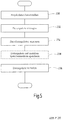
- step 230 the project data 130 are provided.
- step 232 the data packets 132 are generated.
- step 234 the assignment data 134 are generated.
- step 236 the individual data packets 132 are then distributed to the individual project data memories 52, 52 ', 52 ", 52"', 52 “” according to the assignment data 134.
- this closes step 236 does not go directly to step 234. If the data packets are distributed using a mobile storage medium 148, a step 238 is carried out between step 234 and step 236 in which the data packets 132 and the assignment data 134 are stored on the mobile storage medium 148 can be saved.
- system software components 180 are provided.
- the provided system software components 180 are linked.
- the sensors and actuators are specified for the individual aspect blocks 188, ie what is known as I / O mapping is carried out.
- Control software components 212 are provided 246.
- the system software components 180 provided are assigned to the control software components 212 provided.
Description
Die vorliegende Erfindung betrifft eine Sicherheitssteuerung und ein Verfahren zum Steuern einer automatisierten Anlage in Abhängigkeit von Projektdaten gemäß den Oberbegriffen der Ansprüche 1 und 11, wobei die Projektdaten eine auf der Anlage ablaufende Anwendung repräsentieren.The present invention relates to a safety controller and a method for controlling an automated system as a function of project data according to the preambles of
Eine Sicherheitssteuerung im Sinne der vorliegenden Erfindung ist ein Gerät, oder eine Vorrichtung, das bzw. die von Sensoren gelieferte Eingangssignale aufnimmt und daraus durch logische Verknüpfungen und eventuell weitere Signal- oder Datenverarbeitungsschritte Ausgangssignale erzeugt. Die Ausgangssignale können dann Aktuatoren zugeführt werden, die in Abhängigkeit von den Eingangssignalen Aktionen oder Reaktionen in einer gesteuerten Anlage bewirken.A safety controller in the sense of the present invention is a device or a device that receives input signals supplied by sensors and generates output signals therefrom by means of logic operations and possibly further signal or data processing steps. The output signals can then be fed to actuators which, depending on the input signals, cause actions or reactions in a controlled system.
Ein bevorzugtes Anwendungsgebiet für derartige Sicherheitssteuerungen ist die Überwachung von Not-Aus-Tastern, Zwei-Hand-Steuerungen, Schutztüren oder Lichtgittern im Bereich der Maschinensicherheit. Derartige Sensoren werden verwendet, um beispielsweise eine Maschine, von der im Betrieb eine Gefahr für Menschen oder materielle Güter ausgeht, abzusichern. Beim Öffnen der Schutztür oder beim Betätigen des Not-Aus-Tasters wird jeweils ein Signal erzeugt, das der Sicherheitssteuerung als Eingangssignal zugeführt ist. In Reaktion darauf schaltet die Sicherheitssteuerung dann beispielsweise mit Hilfe eines Aktuators den gefahrbringenden Teil der Maschine ab.A preferred area of application for such safety controls is the monitoring of emergency stop buttons, two-hand controls, protective doors or light grids in the field of machine safety. Such sensors are used, for example, to secure a machine that poses a risk to people or material goods during operation. When the protective door is opened or the emergency stop button is pressed, a signal is generated that is fed to the safety control as an input signal. In response to this, the safety control then switches off the dangerous part of the machine, for example with the help of an actuator.
Charakteristisch an einer Sicherheitssteuerung ist im Gegensatz zu einer "normalen" Steuerung, dass die Sicherheitssteuerung selbst dann, wenn bei ihr oder einem mit ihr verbundenen Gerät eine Fehlfunktion auftritt, stets einen sicheren Zustand der gefahrbringenden Anlagen oder Maschinen gewährleistet. Daher werden bei Sicherheitssteuerungen extrem hohe Anforderungen an die eigene Fehlersicherheit gestellt, was einen erheblichen Aufwand bei der Entwicklung und Herstellung zur Folge hat.A characteristic of a safety controller, in contrast to a "normal" controller, is that the safety controller always guarantees a safe state of the hazardous systems or machines even if a malfunction occurs with it or one of the devices connected to it. For this reason, extremely high demands are placed on safety controls for their own fault tolerance, which results in considerable effort in development and manufacture.
In der Regel benötigen Sicherheitssteuerungen vor ihrer Verwendung eine besondere Zulassung durch zuständige Aufsichtsbehörden, wie beispielsweise in Deutschland durch die Berufsgenossenschaften oder den TÜV. Die Sicherheitssteuerung muss dabei vorgegebene Sicherheitsstandards einhalten, die beispielsweise in der europäischen Norm EN 954-1 oder einer vergleichbaren Norm, beispielsweise der Norm IEC 61508 oder der Norm EN ISO 13849-1, niedergelegt sind. Im Folgenden wird daher unter einer Sicherheitssteuerung ein Gerät bzw. eine Vorrichtung verstanden, die zumindest die Sicherheitskategorie 3 der genannten europäischen Norm EN 954-1 erfüllt oder deren Safety Integrity Level (SIL) zumindest die Stufe 2 gemäß der genannten Norm IEC 61508 erreicht.As a rule, safety controls require special approval from the competent supervisory authorities before they can be used, such as in Germany from the employers' liability insurance association or the TÜV. The safety controller must comply with specified safety standards, which are laid down, for example, in the European standard EN 954-1 or a comparable standard, for example the standard IEC 61508 or the standard EN ISO 13849-1. In the following, therefore, a safety controller is understood to mean a device or a device that meets at least
Eine programmierbare Sicherheitssteuerung bietet dem Anwender die Möglichkeit, die logischen Verknüpfungen und gegebenenfalls weitere Signal- oder Datenverarbeitungsschritte mit Hilfe einer Software, dem so genannten Anwenderprogramm, seinen Bedürfnissen entsprechend individuell festzulegen. Daraus resultiert eine große Flexibilität im Vergleich zu früheren Lösungen, bei denen die logischen Verknüpfungen durch eine definierte Verdrahtung zwischen verschiedenen Sicherheitsbausteinen erzeugt wurden. Ein Anwenderprogramm kann beispielsweise mit Hilfe eines handelsüblichen Personalcomputers (PC) und unter Verwendung entsprechend eingerichteter Softwareprogramme erstellt werden. Der Begriff Anwenderprogramm wird dabei so verstanden, dass ein Anwenderprogramm sowohl Quellcode als auch Maschinencode umfasst.A programmable safety control offers the user the possibility of individually defining the logical links and, if necessary, further signal or data processing steps with the help of software, the so-called user program, according to his needs. This results in a Great flexibility compared to previous solutions in which the logical links were created through defined wiring between different safety modules. A user program can be created, for example, with the aid of a commercially available personal computer (PC) and using appropriately set up software programs. The term user program is understood to mean that a user program includes both source code and machine code.
Bei aus einer Vielzahl von Anlagenhardwarekomponenten aufgebauten großen und somit komplexen Anlagen nach dem Stand der Technik kommen üblicherweise verteilte Sicherheitssteuerungen zum Einsatz. Verteilte Sicherheitssteuerungen bestehen aus einer Vielzahl von Steuerungshardwarekomponenten. Hierbei handelt es sich um Steuereinheiten, Sensoren und Aktuatoren. Die einzelnen Steuerungshardwarekomponenten sind einzelnen Anlagenhardwarekomponenten zugeordnet. Hinsichtlich der Hardware zeichnen sich verteilte Sicherheitssteuerungen durch eine große Flexibilität aus. So kann eine Sicherheitssteuerung aus einer beliebigen Anzahl unterschiedlicher Steuerungshardwarekomponenten aufgebaut und somit sehr flexibel an die Gegebenheiten der zu steuernden Anlage angepasst werden. Hinsichtlich der programmier- bzw. softwaretechnischen Realisierung und somit der Belange der Datenverarbeitung sind verteilte Sicherheitssteuerungen jedoch noch nicht optimal. So ist eine Verteilung von Projektdaten, das sind diejenigen Daten, die eine auf der gesteuerten Anlage ablaufende Anwendung repräsentieren, auf die einzelnen Steuerungshardwarekomponenten nicht vorgesehen. Dadurch wird nicht nur die hinsichtlich der hardwaretechnischen Realisierung mögliche Flexibilität in erheblichem Maße eingeschränkt, dies zieht auch weitere Nachteile nach sich. Dadurch, dass die Projektdaten nicht verteilt und somit "vor Ort" verarbeitet werden können, ist ein nicht unerheblicher Datenaustausch zwischen teilweise weit entfernten Steuerungshardwarekomponenten erforderlich. Dies führt zu einer Beeinträchtigung, genauer gesagt zu einer Erhöhung der Reaktionszeit der Sicherheitssteuerung. "Vor Ort" bedeutet in diesem Zusammenhang, dass die Projektdaten dort verarbeitet werden, wo für deren Verarbeitung benötigte Daten verfügbar sind. Also beispielsweise in einer Steuereinheit, die sich in unmittelbarer Nähe eines Sensors befindet, dessen Sensorsignal als Eingangssignal für die Ermittlung eines Ansteuerungssignals für einen Aktuator benötigt wird. Oder die Verarbeitung findet gar in dem Sensor selbst statt. Stattdessen werden zur Vermeidung einer Beeinträchtigung der Reaktionszeit entsprechend ausgelegte Steuerungshardwarekomponenten und Datenbusse eingesetzt, die einen höheren Datenaustausch zulassen, als dies eigentlich erforderlich wäre. Dies erhöht die Kosten für die Realisierung einer Sicherheitssteuerung. Bezüglich der Kosten ist des Weiteren von Nachteil, dass in einzelnen Steuerungshardwarekomponenten, insbesondere in intelligenten Sensoren und intelligenten Aktuatoren, eventuell vorhandener freier Speicher, genauer gesagt Datenspeicher, nicht genutzt wird und stattdessen der in Steuereinheiten enthaltene Datenspeicher größer dimensioniert werden muss, als dies eigentlich erforderlich wäre.In the case of large and thus complex systems according to the state of the art, which are built up from a large number of system hardware components, distributed safety controls are usually used. Distributed safety controls consist of a large number of control hardware components. These are control units, sensors and actuators. The individual control hardware components are assigned to individual system hardware components. With regard to the hardware, distributed safety controls are characterized by great flexibility. A safety controller can be built from any number of different control hardware components and can therefore be adapted very flexibly to the conditions of the system to be controlled. With regard to the programming or software implementation and thus the issues of data processing, however, distributed safety controls are not yet optimal. There is no provision for distributing project data, that is, data that represent an application running on the controlled system, to the individual control hardware components. This not only limits the flexibility that is possible with regard to the hardware implementation to a considerable extent, it also entails further disadvantages. Because the project data cannot be distributed and thus processed "on site", a not inconsiderable exchange of data between control hardware components, some of which are far away, is necessary. This leads to an impairment, more precisely to an increase in the response time of the safety controller. "On site" in this context means that the project data is processed where the data required for its processing is available. For example, in a control unit that is located in the immediate vicinity of a sensor, whose sensor signal is required as an input signal for determining a control signal for an actuator. Or processing even takes place in the sensor itself. Instead, appropriately designed control hardware components and data buses are used to avoid impairment of the response time, which allow a higher exchange of data than would actually be necessary. This increases the cost of implementing a safety controller. Another disadvantage with regard to costs is that in individual control hardware components, in particular in intelligent sensors and intelligent actuators, any available free memory, more precisely data memory, is not used and instead the data memory contained in control units has to be dimensioned larger than is actually necessary were.
Es ist eine Aufgabe der vorliegenden Erfindung, eine Sicherheitssteuerung und ein Verfahren der eingangs genannten Art weiterzubilden, um die Kosten für die Realisierung einer Sicherheitssteuerung zu reduzieren und um eine flexiblere und hinsichtlich der Verfügbarkeit optimierte Sicherheitssteuerung zu ermöglichen.It is an object of the present invention to develop a safety controller and a method of the type mentioned at the outset in order to reduce the costs for the implementation of a safety controller and to enable a more flexible safety controller that is optimized in terms of availability.
Diese Aufgabe wird durch eine Sicherheitssteuerung und ein Verfahren nach den Ansprüchen 1 und 11 gelöst.This object is achieved by a safety controller and a method according to
Der neuen Sicherheitssteuerung und dem neuen Verfahren liegt die Idee zugrunde, in einer Sicherheitssteuerung eine Verteileinheit vorzusehen, die dazu ausgebildet ist, zumindest einen Teil der Projektdaten auf in Steuerungshardwarekomponenten enthaltene Datenspeicher zu verteilen und somit das Verteilen von Projektdaten auf Steuerungshardwarekomponenten, aus denen die Sicherheitssteuerung aufgebaut ist, zu ermöglichen. Somit lassen sich Projektdaten gezielt in einzelnen Datenspeichern, die in verschiedenen Steuerungshardwarekomponenten enthalten sind, abspeichern. Dies ermöglicht auch in sogenannten intelligenten Ein-/Ausgabe-Einheiten Projektdaten abzuspeichern. Hierbei handelt es sich um Sensoren und Aktuatoren, die über Datenverarbeitungseinheiten, beispielsweise Mikroprozessoren, und Datenspeicher verfügen. Dadurch können in einer Sicherheitssteuerung vorhandene Datenspeicher, die ansonsten zu einem Großteil ungenutzt bleiben würden, mit Projektdaten belegt und somit genutzt werden. Dadurch können in einer Sicherheitssteuerung vorhandene Steuereinheiten zukünftig mit kleineren Datenspeichern ausgestattet werden. Dies reduziert die Kosten für eine Sicherheitssteuerung.The new safety control and the new method are based on the idea of providing a distribution unit in a safety control that is designed to distribute at least part of the project data to data memories contained in control hardware components and thus the distribution of project data to control hardware components that make up the safety control is to enable. In this way, project data can be specifically saved in individual data memories that are contained in various control hardware components. This also enables project data to be saved in so-called intelligent input / output units. These are sensors and actuators that have data processing units, for example microprocessors, and data memories. As a result, data memories available in a safety controller, which would otherwise largely remain unused, can be filled with project data and thus used. As a result, control units that are present in a safety controller can be equipped with smaller data memories in the future. This reduces the costs for a safety controller.
Gleichzeitig wird die Reaktionszeit einer Sicherheitssteuerung verringert. Projektdaten können dort abgespeichert werden und stehen somit dort zur Verfügung, wo beispielsweise benötigte Sensorsignale vorliegen oder Ansteuersignale für Aktuatoren bereitzustellen sind. Dadurch reduziert sich der Datenaustausch, was letztlich zu einer Verringerung der Reaktionszeit führt. Die Reduzierung des Datenaustausches führt zudem zu einer Steigerung der Verfügbarkeit der Sicherheitssteuerung. Da weniger Daten auszutauschen sind, treten auch weniger Datenübertragungsfehler auf.At the same time, the response time of a safety controller is reduced. Project data can be saved there and are therefore available where, for example, required sensor signals are present or control signals for actuators are to be provided. This reduces the data exchange, which ultimately leads to a reduction in the response time. The reduction in data exchange also leads to an increase the availability of the safety controller. Since there is less data to be exchanged, there are also fewer data transmission errors.
Das Verteilen und somit Abspeichern von Projektdaten in mehreren Projektdatenspeichern hat zudem hinsichtlich der Realisierung und Handhabe einer Sicherheitssteuerung Vorteile. Wird beispielsweise nach der Projektierung einer Sicherheitssteuerung im Probebetrieb festgestellt, dass die in der Sicherheitssteuerung vorhandene, durch sämtliche Datenspeicher gebildete Speicherkapazität zu gering ausfällt, so kann diese durch Einfügen einer zusätzlichen Steuerungshardwarekomponente, die über einen Datenspeicher verfügt, vergrößert werden. Die Projektdaten können dann auf die bisherigen und den zusätzlichen Datenspeicher neu verteilt werden. Die Sicherheitssteuerung ist somit beliebig skalierbar.Distributing and thus saving project data in several project data memories also has advantages with regard to the implementation and handling of a safety controller. If, for example, after planning a safety controller in trial operation, it is found that the memory capacity available in the safety controller and formed by all data memories is too small, this can be increased by adding an additional control hardware component that has a data memory. The project data can then be redistributed to the previous and additional data memories. The safety controller can therefore be scaled as required.
Ist zudem der in einer Steuerungshardwarekomponente enthaltene Datenspeicher beispielsweise als eine entnehmbare Speicherkarte ausgebildet, so können bei einem gegebenenfalls erforderlichen Geräteaustausch die für die neue Steuerungshardwarekomponente benötigten Projektdaten in einfacher Art und Weise bereitgestellt werden. Aus der zu entfernenden defekten Steuerungshardwarekomponente ist lediglich die Speicherkarte zu entnehmen und in die neue einzufügende Steuerungshardwarekomponente einzusetzen. Somit lassen sich beispielsweise Adressdaten, Konfigurationsdaten und Programmdaten bereitstellen, ohne dass hierfür beispielsweise ein Notebook an die neue Steuerungshardwarekomponente anzuschließen ist.If the data memory contained in a control hardware component is also designed, for example, as a removable memory card, the project data required for the new control hardware component can be provided in a simple manner if a device replacement is necessary. All that is required is to remove the memory card from the defective control hardware component to be removed and insert it into the new control hardware component to be inserted. Thus, for example, address data, configuration data and program data can be made available without a notebook having to be connected to the new control hardware component for this purpose.
Die Projektdaten umfassen Programmdaten und/oder Konfigurationsdaten und/oder Parametrisierungsdaten.The project data include program data and / or configuration data and / or parameterization data.
Die Programmdaten repräsentieren dabei das Anwenderprogramm und werden beim Erstellen des Anwenderprogramms erzeugt. Die Konfigurationsdaten repräsentieren einzelne Teilaspekte der Datenübertragung. Es handelt sich dabei beispielsweise um eine Zykluszeit, um Verknüpfungsdaten, die festlegen, welche der Steuerungshardwarekomponenten untereinander verbunden sind, oder um Daten, die repräsentieren, welche Sensoren bzw. Aktuatoren welchen Eingängen bzw. Ausgängen einzelner Steuereinheiten zugeordnet sind, oder um Daten, die die zwischen einzelnen Steuerungshardwarekomponenten auszutauschenden Daten beispielsweise in ihrer Art festlegen. Es handelt sich somit um Daten, die die Konfiguration der verteilt realisierten Sicherheitssteuerung repräsentieren. Die Konfigurationsdaten können beim Erstellen des Anwenderprogramms erzeugt werden. Sie können aber auch nach Erstellen des Anwenderprogramms in einem gewissen Umfang erzeugt oder verändert werden. Die Parametrisierungsdaten repräsentieren Wertebereiche für einzelne im Anwenderprogramm verwendete Variablen oder Funktionalitäten. Diese Daten können beim Erstellen des Anwenderprogramms festgelegt werden oder aber zu einem späteren Zeitpunkt erzeugt werden. Diese Maßnahme ermöglicht eine besonders effektive Optimierung der Sicherheitssteuerung hinsichtlich der Rechenleistung oder der Reaktionszeit. So können Programmdaten dort abgespeichert werden, wo deren Verarbeitung erfolgt. Konfigurationsdaten und Parametrisierungsdaten können dort abgespeichert werden, wo diejenigen Einheiten verbaut sind, für die diese bestimmt sind.The program data represent the user program and are generated when the user program is created. The configuration data represent individual aspects of the data transmission. This involves, for example, a cycle time, link data that determine which of the control hardware components are connected to one another, or data that represent which sensors or actuators, which inputs or outputs of individual control units are assigned, or to data that determine the type of data to be exchanged between individual control hardware components, for example. It is therefore data that represent the configuration of the safety control that is implemented in a distributed manner. The configuration data can be generated when creating the user program. However, they can also be created or changed to a certain extent after the user program has been created. The parameterization data represent value ranges for individual variables or functionalities used in the user program. These data can be specified when the user program is created or can be created at a later point in time. This measure enables a particularly effective optimization of the safety control in terms of computing power or response time. In this way, program data can be saved where they are processed. Configuration data and parameterization data can be stored where those units are installed for which they are intended.
Zumindest ein Teil der Steuerungshardwarekomponenten enthält eine Datenverarbeitungseinheit, wobei für die jeweilige Datenverarbeitungseinheit bestimmte Projektdaten in demjenigen Projektdatenspeicher gespeichert sind, der in derjenigen Steuerungshardwarekomponente enthalten ist, in der die Datenverarbeitungseinheit enthalten ist.At least some of the control hardware components contain a data processing unit, project data specific to the respective data processing unit being stored in that project data memory that is contained in that control hardware component in which the data processing unit is contained.
Dieses Prinzip der lokalen Datenhaltung, bei dem die Projektdaten dort gespeichert werden, wo sie verarbeitet werden, ermöglicht eine schnelle und besonders effektive Bearbeitung von Steuerungsaufgaben und somit eine Reduzierung der Reaktionszeit einer Sicherheitssteuerung. Bei einer Datenverarbeitungseinheit kann es sich um eine Einheit handeln, der Daten als Eingangsdaten für eine Operation zugeführt werden und die als Ergebnis dieser Operation in Abhängigkeit der Eingangsdaten ermittelte Ausgangsdaten ausgibt. Unter einer Datenverarbeitungseinheit kann aber auch eine Einheit verstanden werden, der Daten dahingehend zugeführt werden, diese an eine andere Einheit weiterzuleiten. Sicherheitssteuerungen enthalten Datenverarbeitungseinheiten in unterschiedlichster Ausgestaltungsform. So kommen beispielsweise datenbasierte Nachrichtenvermittlungseinheiten zum Einsatz. Diese stellen beispielsweise von der eigenen Steuereinheit erzeugte Daten anderen Steuereinheiten zur Verfügung und lesen von anderen Steuereinheiten erzeugte Daten ein, die in der eigenen Steuereinheit zur weiteren Verarbeitung benötigt werden. Solche Datenverarbeitungseinheiten sind unter der Bezeichnung Databroker bekannt. Auch kann es sich um ereignisbasierte Nachrichtenvermittlungseinheiten handeln. Solche Nachrichtenvermittlungseinheiten versenden ein Signal, wenn in der eigenen Steuereinheit eine definierte Bedingung erfüllt ist, um in einer anderen Steuereinheit bzw. in der zu steuernden Anlage eine definierte Reaktion auszulösen. In entsprechender Weise empfangen solche Nachrichtenvermittlungseinheiten auch solche Signale. Solche Nachrichtenvermittlungseinheit sind unter der Bezeichnung Eventbroker bekannt. Des Weiteren kommen auch Verbindungseinheiten zum Einsatz, die benötigt werden, um überhaupt einen Datenaustausch zwischen einzelnen Steuerungshardwarekomponenten zu ermöglichen. Solche Datenverarbeitungseinheiten werden als Datenbusschnittstellen bezeichnet. Darüber hinaus handelt es sich auch bei einem Projektdatenspeicher um eine Datenverarbeitungseinheit, da der Projektdatenspeicher nicht nur Projektdaten speichern sondern auch Projektdaten anfordern und weiterleiten kann. Je nachdem, wie die Datenverarbeitungseinheit ausgestaltet ist, unterscheiden sich die für die Datenverarbeitungseinheit jeweils gespeicherten Projektdaten. Für einen Databroker, einen Eventbroker oder eine Datenbusschnittstelle werden beispielsweise Konfigurationsdaten und Parametrierungsdaten abgespeichert. Für einen Projektdatenspeicher werden neben Parametrierungsdaten und Konfigurationsdaten auch Projektdaten abgespeichert, vorzugsweise diejenigen Projektdaten, die in der Steuereinheit verarbeitet werden, in der der Projektdatenspeicher enthalten ist.This principle of local data storage, in which the project data is stored where it is processed, enables fast and particularly effective processing of control tasks and thus a reduction in the response time of a safety controller. A data processing unit can be a unit to which data is supplied as input data for an operation and which outputs output data determined as a result of this operation as a function of the input data. A data processing unit can, however, also be understood to mean a unit to which data is supplied in order to pass it on to another unit. Safety controls contain data processing units in the most varied of configurations. For example, data-based message switching units are used. For example, these make data generated by their own control unit available to other control units and read data generated by other control units, which are required in the own control unit for further processing. Such data processing units are known as data brokers. Event-based message switching units can also be involved. Such message switching units send a signal when a defined condition is met in their own control unit in order to trigger a defined reaction in another control unit or in the system to be controlled. Such message switching units also receive such signals in a corresponding manner. Such message switching units are known as event brokers. In addition, connection units are also used that are required to enable data exchange between individual control hardware components at all. Such data processing units are referred to as data bus interfaces. In addition, a project data memory is also a data processing unit, since the project data memory can not only store project data but also request and forward project data. Depending on how the data processing unit is designed, the respective project data stored for the data processing unit differ. For a data broker, an event broker or a data bus interface, for example, configuration data and parameterization data are stored. In addition to parameterization data and configuration data, project data are also stored for a project data memory, preferably those project data that are processed in the control unit in which the project data memory is contained.
Zumindest einer der Projektdatenspeicher ist dazu ausgebildet, ihm zugeführte Projektdaten an zumindest einen anderen Projektdatenspeicher weiterzuleiten oder in einem anderen Projektdatenspeicher gespeicherte Projektdaten anzufordern.At least one of the project data memories is designed to forward project data supplied to it to at least one other project data memory or to request project data stored in another project data memory.
Diese Maßnahme ermöglicht eine flexible Verteilung der Projektdaten auf die in einer Sicherheitssteuerung enthaltenen Projektdatenspeicher. Dadurch, dass einer der Projektdatenspeicher dazu ausgebildet ist, Projektdaten weiterzuleiten, kann dieser für das Verteilen der Projektdaten auf die in einer Sicherheitssteuerung angeordneten Projektdatenspeicher eingesetzt werden. Dadurch dass zumindest einer der Projektdatenspeicher dazu ausgebildet sind, Projektdaten von einem anderen Projektdatenspeicher anzufordern, ist es nicht zwingend erforderlich, die in einer Steuerungshardwarekomponente benötigten Projektdaten auf demjenigen Projektdatenspeicher abzuspeichern, der in dieser Komponente angeordnet ist. Stattdessen ist es möglich, diese Projektdaten auf einem beliebigen Projektdatenspeicher abzuspeichern, da diese jederzeit angefordert werden können. Vorteilhafterweise ist zumindest einer der Projektdatenspeicher mit beiden Funktionsmerkmalen ausgestattet, d.h. dazu ausgebildet, sowohl Projektdaten weiterzuleiten als auch Projektdaten anzufordern. Dies ermöglicht eine besonders flexible Verteilung der Projektdaten. Ein Projektdatenspeicher, der dazu ausgebildet ist, Projektdaten zu speichern, weiterzuleiten und anzufordern, kann aufgrund dieses Funktionsumfanges auch als Projektdatenserver, verkürzt als Projektserver bezeichnet werden.In einer weiteren Ausgestaltung handelt es sich bei der Verteileinheit um einen der Projektdatenspeicher.This measure enables a flexible distribution of the project data to the project data memory contained in a safety controller. Because one of the project data memories is designed to forward project data, it can be used to distribute the project data to the project data memories arranged in a safety controller. Because at least one of the project data memories is designed to request project data from another project data memory, it is not absolutely necessary that the data in a control hardware component to save the required project data on the project data memory that is arranged in this component. Instead, it is possible to save this project data in any project data memory, as this can be requested at any time. At least one of the project data memories is advantageously equipped with both functional features, ie designed to both forward project data and request project data. This enables a particularly flexible distribution of the project data. A project data memory, which is designed to store, forward and request project data, can also be referred to as a project data server, or project server for short, due to this range of functions. In a further embodiment, the distribution unit is one of the project data memories.
Diese Maßnahme besitzt den Vorteil, dass für das Verteilen der Projektdaten keine zusätzliche Einheit in der Sicherheitssteuerung vorzusehen ist. Das Verteilen der Projektdaten wird von einem der ohnehin in der Sicherheitssteuerung vorhandenen Projektdatenspeicher durchgeführt. Dies ermöglicht eine kostengünstige Realisierung der Sicherheitssteuerung. Ein weiterer Vorteil besteht darin, dass in einem Projektdatenspeicher vorhandene und hinsichtlich einer Verarbeitung von Projektdaten optimierte Funktionalitäten für das Verteilen der Projektdaten verwendet werden können. Als Beispiel sei das Interface eines Projektdatenspeichers angeführt. Demjenigen Projektdatenspeicher, der als Verteileinheit eingesetzt wird, kommt beim Verteilen der Projektdaten die Funktion eines Masters zu. Die restlichen Projektdatenspeicher nehmen jeweils die Funktion eines Slaves ein. Vorteilhafterweise verfügt derjenige Projektdatenspeicher, der als Verteileinheit eingesetzt wird, über eine größere Speicherkapazität, als dies für den Betrieb derjenigen Steuerungshardwarekomponente, in der er angeordnet ist, erforderlich wäre. Und zwar aus folgendem Grund: Beim Verteilen der Projektdaten werden Daten erzeugt, die für den späteren Betrieb der Sicherheitssteuerung benötigt werden. Diese können somit in besagtem Projektdatenspeicher zwischengespeichert werden.This measure has the advantage that no additional unit needs to be provided in the safety controller for distributing the project data. The project data is distributed from one of the project data memories already present in the safety controller. This enables a cost-effective implementation of the safety control. Another advantage is that functionalities that are present in a project data memory and that have been optimized with regard to the processing of project data can be used for distributing the project data. The interface of a project data memory is given as an example. The project data memory that is used as a distribution unit has the function of a master when distributing the project data. The remaining project data memories each take on the function of a slave. The project data memory that is used as a distribution unit advantageously has a greater storage capacity than would be required for the operation of that control hardware component in which it is arranged. For the following reason: When the project data is distributed, data is generated that is required for later operation of the safety controller. These can thus be cached in the aforementioned project data memory.
Üblicherweise werden die Projektdaten unter Verwendung eines auf einer Programmiereinheit ablaufenden Programmiertools erstellt. Dabei handelt es sich in der Regel um eine von der Sicherheitssteuerung baulich getrennte Einheit. Die Programmiereinheit umfasst beispielsweise einen als Personalcomputer ausgebildeten Computer. Für die Übertragung der Projektdaten von der Programmiereinheit auf denjenigen Projektdatenspeicher, der als Verteileinheit eingesetzt wird, sind mehrere Alternativen denkbar. So kann die Programmiereinheit beispielsweise über ein Kabel mit derjenigen Steuerungshardwarekomponente, in der der Projektdatenspeicher enthalten ist, oder gar mit dem Projektdatenspeicher selbst verbunden werden. Diese Ausgestaltung eignet sich besonders dafür, wenn die vollständigen Projektdaten in einem einzigen Vorgang in die Sicherheitssteuerung eingespielt werden sollen. In einer weiteren Ausgestaltung können die Projektdaten unter Verwendung eines mobilen Speichermediums auf den Projektdatenspeicher übertragen werden. Als mobiles Speichermedium kommen beispielsweise Speicherkarten, die als SD-Card (Secure Digital Memory Card) oder CF-Card (Compact Flash Card) ausgebildet sein können, oder ein USB-Stick (Universal Serial Bus) in Frage. Bei der Verwendung eines mobilen Speichermediums ist für die Initialisierung des Verteilvorgangs vorteilhafterweise eine bewusste Benutzerhandlung vorzunehmen. Beispielsweise ist an derjenigen Steuerungshardwarekomponente, in die das mobile Speichermedium eingeführt ist, eine bestimmte Tastenkombination zu drücken oder ein Taster zu betätigen oder über eine grafische Oberfläche eine definierte Eingabe vorzunehmen. Bei der direkten Übertragung der Projektdaten von der Programmiereinheit auf den Projektdatenspeicher wird der Verteilvorgang vorteilhafterweise durch die Programmiereinheit automatisch initialisiert.The project data are usually created using a programming tool that runs on a programming unit. This is usually a structurally separate unit from the safety controller. The programming unit comprises, for example, a computer designed as a personal computer. For the transfer Several alternatives are conceivable for transferring the project data from the programming unit to the project data memory that is used as a distribution unit. For example, the programming unit can be connected via a cable to that control hardware component in which the project data memory is contained, or even to the project data memory itself. This configuration is particularly suitable when the complete project data is to be imported into the safety controller in a single process. In a further embodiment, the project data can be transferred to the project data memory using a mobile storage medium. As a mobile storage medium, for example, memory cards, which can be designed as SD cards (Secure Digital Memory Cards) or CF cards (Compact Flash Cards), or a USB stick (Universal Serial Bus) can be used. When using a mobile storage medium, a conscious user action is advantageously to be carried out for the initialization of the distribution process. For example, on the control hardware component into which the mobile storage medium is inserted, a specific key combination has to be pressed or a button has to be pressed or a defined input has to be made via a graphic surface. With the direct transfer of the project data from the programming unit to the project data memory, the distribution process is advantageously initialized automatically by the programming unit.
Die Verwendung eines mobilen Speichermediums hat verschiedene Vorteile. So ist es möglich, Projektdaten lediglich auf ausgewählte Steuerungshardwarekomponenten aufzuspielen, indem das mobile Speichermedium gezielt an diese Steuerungshardwarekomponenten angeschlossen wird. Ein weiterer Vorteil besteht darin, dass das mobile Speichermedium auch zu Sicherungszwecken verwendet werden kann. So kann der in einer Sicherheitssteuerung gespeicherte Maschinencode auf dem mobilen Speichermedium gespeichert und bei Bedarf erneut in die Sicherheitssteuerung eingelesen werden.The use of a mobile storage medium has various advantages. It is thus possible to only upload project data to selected control hardware components by specifically connecting the mobile storage medium to these control hardware components. Another advantage is that the mobile storage medium can also be used for backup purposes. The machine code stored in a safety controller can be stored on the mobile storage medium and read into the safety controller again if necessary.
In einer weiteren Ausgestaltung der Erfindung handelt es sich bei der Verteileinheit um eine externe Verteileinheit, die zumindest zeitweise an eine in der Sicherheitssteuerung hierfür vorgesehene Schnittstelle angeschlossen ist.In a further embodiment of the invention, the distribution unit is an external distribution unit which is connected at least temporarily to an interface provided for this purpose in the safety controller.
Besonders vorteilhaft ist es, wenn sich die externe Verteileinheit in der Programmiereinheit befindet, auf der das Programmiertool läuft, mit dem die Projektdaten erstellt werden. Dadurch können die Projektdaten direkt von der Programmiereinheit auf die Sicherheitssteuerung übertragen werden. Dies ist zum einen wenig aufwändig. Zum anderen wird dadurch die Fehlersicherheit der Sicherheitssteuerung erhöht, da potentielle Fehlerquellen hinsichtlich der Übertragung der Projektdaten ausgeschlossen werden. Ein weiterer Vorteil dieser Ausgestaltung besteht darin, dass nach Fertigstellen der Projektdaten in einem so genannten Probetrieb, bei dem die Funktionalität der Sicherheitssteuerung und der zu steuernden Anlage getestet wird, und bei dem gegebenenfalls festgestellt wird, dass Änderungen an den Projektdaten vorzunehmen sind, diese in einfacher Art und Weise aktualisiert werden können.It is particularly advantageous if the external distribution unit is located in the programming unit on which the programming tool that is used to create the project data runs. This allows the project data to be transferred directly from the programming unit to the safety controller. On the one hand, this is not very complex. On the other hand, this increases the fail-safe safety of the safety controller, since potential sources of error with regard to the transfer of the project data are excluded. A further advantage of this embodiment is that after the project data has been completed in a so-called trial operation, in which the functionality of the safety controller and the system to be controlled is tested and in which it is determined that changes to the project data are to be made, these in can be updated easily.
Die Übertragung der Projektdaten von der Programmiereinheit auf die Sicherheitssteuerung erfolgt beispielsweise Kabel gebunden. Vorteilhafterweise ist dabei die Programmiereinheit nicht permanent, sondern nur zeitweise mit der Sicherheitssteuerung verbunden. Beispielsweise für den Zeitraum des Programmierens, also für den Zeitraum, in dem die Projektdaten generiert werden. Oder gar nur für den Zeitraum, während dem die Projektdaten von der Programmiereinheit auf die Sicherheitssteuerung übertragen werden. Die Programmiereinheit kann als Teil der Sicherheitssteuerung aufgefasst werden, da mit Programmiereinheit die Projektdaten, insbesondere das Anwenderprogramm für die zu steuernde Anlage generiert werden.The project data is transferred from the programming unit to the safety controller, for example, using a cable. Advantageously, the programming unit is not permanently connected to the safety controller, but only temporarily. For example, for the period of programming, i.e. for the period in which the project data is generated. Or even only for the period during which the project data is being transferred from the programming unit to the safety controller. The programming unit can be understood as part of the safety control, since the project data, in particular the user program for the system to be controlled, are generated with the programming unit.
In einer weiteren Ausgestaltung der Erfindung handelt es sich bei den Steuerungshardwarekomponenten um Steuereinheiten und/oder Sensoren und/oder Aktuatoren.In a further embodiment of the invention, the control hardware components are control units and / or sensors and / or actuators.
Es können somit nicht nur die in Steuereinheiten vorhandenen Speicher als Projektdatenspeicher verwendet werden, sondern auch die in so genannten intelligenten Sensoren und intelligenten Aktuatoren vorhandenen Speicher. Dies ermöglicht eine besonders flexible Verteilung der Projektdaten, insbesondere dahingehend, dass direkt vor Ort eine teilumfängliche Verarbeitung der Projektdaten erfolgen kann. Dies trägt dazu bei, die Reaktionszeit der Sicherheitssteuerung zu verbessern.Thus, not only the memories present in control units can be used as project data memories, but also the memories present in so-called intelligent sensors and intelligent actuators. This enables a particularly flexible distribution of the project data, in particular to the effect that partial processing of the project data can take place directly on site. This helps to improve the response time of the safety controller.
In einer weiteren Ausgestaltung der Erfindung sind die Projektdaten in eine Vielzahl von Datenpaketen aufgeteilt, wobei die einzelnen Datenpakete jeweils zumindest einem der Projektdatenspeicher zugeordnet sind.In a further embodiment of the invention, the project data are divided into a multiplicity of data packets, the individual data packets each being assigned to at least one of the project data memories.
Diese Maßnahme hat den Vorteil, dass die Projektdaten entsprechend einem bestimmten Verteilkriterium gezielt einzelnen Projektdatenspeichern zugewiesen werden können. Somit kann eine Sicherheitssteuerung durch entsprechende Wahl des Verteilkriteriums hinsichtlich unterschiedlicher Parameter optimiert werden.This measure has the advantage that the project data can be specifically assigned to individual project data memories in accordance with a specific distribution criterion. In this way, a safety controller can be optimized with regard to different parameters by appropriate selection of the distribution criterion.
In einer weiteren Ausgestaltung der Erfindung ist für das Erstellen der Projektdaten eine Programmiereinheit vorgesehen, wobei die Programmiereinheit dazu ausgebildet ist, Zuordnungsdaten zu erzeugen, wobei die Verteileinheit ferner dazu ausgebildet ist, die Projektdaten in Abhängigkeit der Zuordnungsdaten auf die Projektdatenspeicher zu verteilen.In a further embodiment of the invention, a programming unit is provided for creating the project data, the programming unit being designed to generate assignment data, the distribution unit also being designed to distribute the project data to the project data memory as a function of the assignment data.
Diese Maßnahme hat den Vorteil, dass die Projektdaten nach einem beliebig festlegbaren Verteilkriterium auf die einzelnen Projektdatenspeicher verteilt werden können. Gleichzeitig wird dadurch eine fehlerfreie und, sofern erforderlich, beliebig oft reproduzierbare Verteilung der Projektdaten gewährleistet. Was die Verbindlichkeit der Zuordnungsdaten angeht, so sind unterschiedliche Ansätze denkbar. Beispielsweise können die Zuordnungsdaten den Charakter eines Vorschlages haben und eine Präferenzliste darstellen, die beispielsweise der Ersteller der Projektdaten oder der Betreiber der zu steuernden Anlage abändern kann. Andererseits kann auch vorgesehen sein, dass eine Abänderung der Zuordnungsdaten nicht möglich ist, so dass in diesem Fall das Verteilen der Projektdaten vollständig automatisch abläuft.This measure has the advantage that the project data can be distributed to the individual project data memories according to a freely definable distribution criterion. At the same time, an error-free and, if necessary, as often reproducible distribution of the project data is guaranteed. As far as the binding nature of the assignment data is concerned, different approaches are conceivable. For example, the assignment data can have the character of a proposal and represent a list of preferences which, for example, the creator of the project data or the operator of the system to be controlled can change. On the other hand, it can also be provided that the assignment data cannot be changed, so that in this case the project data is distributed completely automatically.
Die Zuordnungsdaten können beispielsweise folgende Angaben enthalten: Für jeden in der Sicherheitssteuerung enthaltenen Projektdatenspeicher sind die auf diesem abzuspeichernden bzw. die dann auf diesem abgespeicherten Datenpakete aufgeführt. Somit steht fest, welches Datenpaket zu welcher Steuerungshardwarekomponente bzw. zu welcher Datenverarbeitungseinheit gehört. Auch kann durch die Zuordnungsdaten die Reihenfolge der Projektdatenspeicher festgelegt sein, in der diese beim Verteilen der Projektdaten berücksichtigt werden. Solch eine Reihenfolge sieht vor, dass auf jeden Fall der Projektdatenspeicher zuerst berücksichtigt wird, der als Verteileinheit eingesetzt wird. Die Zuordnungsdaten können für jeden einzelnen Projektdatenspeicher eine Information darüber enthalten, welche Datenpakete auf dem jeweiligen Projektdatenspeicher abzuspeichern sind bzw. auf diesem dann abgespeichert sind. Darüber hinaus kann für jede Steuerungshardwarekomponente eine Information vorgesehen sein, die angibt, auf welchen Projektdatenspeichern sich die Projektdaten der jeweiligen Steuerungshardwarekomponente befinden. Diese Information wird beispielsweise beim Booten oder Rekonfigurieren der Sicherheitssteuerung benötigt. Liegt diese Information vor, kann jede Steuerungshardwarekomponente bzw. jede Datenverarbeitungseinheit die für sie vorgesehenen Projektdaten von den entsprechenden Projektdatenspeichern, in denen diese gespeichert sind, abrufen. Es ist auch denkbar, einen Teilumfang der Zuordnungsdaten erst beim Verteilvorgang selbst zu erzeugen. Dies bietet sich beispielsweise für die Daten an, angeben, auf welchen Projektdatenspeichern sich die Projektdaten der jeweiligen Steuerungshardwarekomponente befinden.The assignment data can contain, for example, the following information: For each project data memory contained in the safety controller, the data packets to be saved on this or the data packets then saved on it are listed. It is therefore clear which data packet belongs to which control hardware component or which data processing unit. The assignment data can also determine the order of the project data memories in which they are used when distributing the Project data are taken into account. Such an order provides that the project data memory that is used as the distribution unit is always taken into account first. For each individual project data memory, the assignment data can contain information about which data packets are to be stored in the respective project data memory or are then stored there. In addition, information can be provided for each control hardware component which specifies the project data memories on which the project data of the respective control hardware component are located. This information is required, for example, when booting or reconfiguring the safety controller. If this information is available, each control hardware component or each data processing unit can call up the project data provided for them from the corresponding project data memories in which they are stored. It is also conceivable to only generate part of the assignment data during the distribution process itself. This is useful, for example, for the data, specifying the project data memories on which the project data of the respective control hardware components are located.
In einer weiteren Ausgestaltung der Erfindung ist die Programmiereinheit dazu ausgebildet, die Zuordnungsdaten in Abhängigkeit zumindest einer Datenverarbeitungskenngröße zu ermitteln.In a further embodiment of the invention, the programming unit is designed to determine the assignment data as a function of at least one data processing parameter.
Die Datenverarbeitungskenngröße repräsentiert dabei eine für die Datenverarbeitung relevante Kenngröße einer bei der Datenverarbeitung eingesetzten Komponente. Hierbei kann es sich beispielsweise um die Taktfrequenz eines Mikroprozessors, um die Datenraten eines Databroker oder eines Eventbroker oder einer Datenbusschnittstelle oder um die Speicherkapazität eines Projektdatenspeichers handeln. Werden bei der Ermittlung der Zuordnungsdaten Datenverarbeitungskenngrößen der Steuerungshardwarekomponenten oder einzelner in diesen verbauten Einheiten berücksichtigt, so kann eine Verteilung der Projektdaten unter dem Gesichtspunkt einer optimierten Datenverarbeitung erfolgen. So können Projektdaten, zu deren Verarbeitung eine hohe Rechenleistung erforderlich ist, beispielsweise in Steuerungshardwarekomponenten gespeichert werden, die mit einem leistungsfähigen Mikroprozessor ausgestattet sind. Zudem können Datenpakete in Abhängigkeit deren Größe auf die in der Sicherheitssteuerung vorhandenen Datenspeicher verteilt werden. Beispielsweise können kleine Datenpaketen gezielt in Datenspeichern mit geringer Speicherkapazität abgespeichert werden. Diese Maßnahme eignet sich besonders vorteilhaft für eine vollständig automatische Verteilung der Projektdaten auf die Projektdatenspeicher.The data processing parameter represents a parameter relevant for data processing of a component used in data processing. This can be, for example, the clock frequency of a microprocessor, the data rates of a data broker or an event broker or a data bus interface or the storage capacity of a project data memory. If data processing parameters of the control hardware components or individual units built into them are taken into account when determining the assignment data, then the project data can be distributed from the point of view of optimized data processing. For example, project data that requires high computing power to process can be stored in control hardware components that are equipped with a powerful microprocessor. In addition, depending on their size, data packets can be based on those in the safety controller Data storage are distributed. For example, small data packets can be stored in a targeted manner in data memories with a small storage capacity. This measure is particularly advantageous for a completely automatic distribution of the project data to the project data memory.
In einer weiteren Ausgestaltung der Erfindung ist die Programmiereinheit dazu ausgebildet, die Zuordnungsdaten in Abhängigkeit zumindest einer Funktionszuordnungsgröße zu ermitteln.In a further embodiment of the invention, the programming unit is designed to determine the assignment data as a function of at least one function assignment variable.
Die Funktionszuordnungsgröße repräsentiert dabei für ein einzelnes Datenpaket oder einen Verbund von Datenpaketen denjenigen Projektdatenspeicher, in dem dieses Datenpaket oder dieser Verbund abzuspeichern ist. Der Projektdatenspeicher ist dabei dadurch festgelegt, dass das Abspeichern in demjenigen Projektdatenspeicher erfolgen soll, der sich in derjenigen Steuerungshardwarekomponente, insbesondere derjenigen Steuereinheit, befindet, in der die Projektdaten verarbeitet werden. Beispielsweise aufgrund der räumlichen Nähe eines Sensors, dessen Signale als Eingangssignale benötigt werden, und/oder der räumlichen Nähe eines Aktuators, der durch die ermittelten Ansteuersignale angesteuert wird. Diese Maßnahme ermöglicht eine kurze Reaktionszeit der Sicherheitssteuerung, da die Projektdaten vor Ort vorgehalten werden und somit der Datenaustausch zwischen einzelnen Steuerungshardwarekomponenten auf ein Minimum reduziert wird. Vorteilhafterweise werden die Funktionszuordnungsgrößen vom Programmierer eines Anwenderprogramms vorgegeben, indem er festlegt, welche Umfänge des Anwenderprogramms auf weichen Steuerungshardwarekomponenten, beispielsweise Steuereinheiten, ablaufen sollen.The function allocation variable represents for an individual data packet or a group of data packets that project data memory in which this data packet or this group is to be stored. The project data memory is defined in that the storage is to take place in that project data memory which is located in that control hardware component, in particular that control unit, in which the project data are processed. For example, due to the spatial proximity of a sensor, the signals of which are required as input signals, and / or the spatial proximity of an actuator that is controlled by the determined control signals. This measure enables a short reaction time of the safety controller, since the project data is kept on site and thus the data exchange between the individual control hardware components is reduced to a minimum. The function assignment variables are advantageously specified by the programmer of a user program in that he stipulates which scopes of the user program should run on soft control hardware components, for example control units.
In einer weiteren Ausgestaltung der Erfindung ist zumindest ein Teil der Projektdaten redundant in den Projektdatenspeichern gespeichert.In a further embodiment of the invention, at least part of the project data is stored redundantly in the project data memory.
Das redundante Abspeichern der Datenpakete wird dadurch erreicht, dass die jeweiligen Datenpakete gedoppelt werden. Die gedoppelten Datenpakete werden dann eigenständig auf die Projektdatenspeicher verteilt, und zwar unter der Maßgabe, dass das ursprüngliche und das gedoppelte Datenpaket jeweils in einem anderen Projektdatenspeicher gespeichert werden. Diese Maßnahme hat den Vorteil, dass die Verfügbarkeit der Sicherheitssteuerung und somit der gesteuerten Anlage erhöht wird. Fällt beispielsweise eine nicht-sicherheitsrelevante Steuerungshardwarekomponente aus, so stehen nach wie vor die Projektdaten, die in ihrem Projektdatenspeicher gespeichert waren, zur Verfügung, da diese noch in einem anderen Projektdatenspeicher vorliegen. Auch wird dadurch der Austausch einer defekten Steuerungshardwarekomponente erleichtert. Es ist lediglich die defekte Komponente gegen eine neue Komponente auszutauschen. Die für die neue Komponente benötigen Projektdaten können beispielsweise automatisch von den jeweiligen Projektdatenspeichern, auf denen diese noch abgelegt sind, angefordert und in dem Projektdatenspeicher der neuen Komponente gespeichert werden. Das redundante Speichern der Projektdaten ermöglicht auch eine Parallelisierung einzelner Steuerungsaufgaben.The redundant storage of the data packets is achieved by duplicating the respective data packets. The duplicated data packets are then distributed independently to the project data memories, with the proviso that the original and the duplicated data packets are each in a different project data memory get saved. This measure has the advantage that the availability of the safety control and thus of the controlled system is increased. If, for example, a non-safety-relevant control hardware component fails, the project data that were stored in your project data memory are still available because they are still available in another project data memory. This also makes it easier to replace a defective control hardware component. All you have to do is replace the defective component with a new component. The project data required for the new component can, for example, be automatically requested from the respective project data memories on which they are still stored and stored in the project data memory of the new component. The redundant storage of the project data also enables individual control tasks to be carried out in parallel.
In einer weiteren Ausgestaltung der Erfindung ist zumindest ein Teil der Projektdatenspeicher dazu ausgebildet, die jeweils zugeführten Projektdaten nullspannungssicher zu speichern.In a further embodiment of the invention, at least some of the project data memories are designed to store the project data supplied in each case in a non-volatile manner.
Diese Maßnahme hat den Vorteil, dass die Projektdaten beispielsweise nach einem Spannungsausfall oder nach Abschalten der Sicherheitssteuerung nach wie vor vorliegen. Dadurch wird die Verfügbarkeit der Sicherheitssteuerung erhöht. Es ist keine Neuinitialisierung der Sicherheitssteuerung erforderlich. Beispielsweise werden hierfür Speicherkarten in Form von SD-Cards oder CF-Cards verwendet oder aber Flashspeicher eingesetzt.This measure has the advantage that the project data is still available, for example after a power failure or after the safety controller has been switched off. This increases the availability of the safety controller. The safety controller does not need to be re-initialized. For example, memory cards in the form of SD cards or CF cards are used for this, or flash memories are used.
Vorzugsweise kann während des Verteilens der Projektdaten auf die einzelnen Projektdatenspeicher der Fortgang des Verteilvorgangs durch grafische Mittel angezeigt werden. Dadurch kann sich beispielsweise ein Betreiber der zu steuernden Anlage in einfacher Art und Weise über den Zustand des Verteilvorgangs informieren.The progress of the distribution process can preferably be displayed by graphic means during the distribution of the project data to the individual project data stores. In this way, for example, an operator of the system to be controlled can easily find out about the status of the distribution process.
Vorzugsweise enthält jede Steuerungshardwarekomponente einen Projektdatenspeicher. Dies ermöglicht eine optimale Verteilung der Projektdaten. Die Projektdaten stehen an den Orten zur Verfügung, an denen sie benötigt werden.Each control hardware component preferably contains a project data memory. This enables an optimal distribution of the project data. The project data is available wherever it is needed.
Die auf der zu steuernden Anlage ablaufende Anwendung kann auch als Prozess bezeichnet werden, der sowohl Standardsteuerungsaufgaben als auch Sicherheitssteuerungsaufgaben umfasst.The application running on the system to be controlled can also be referred to as a process, which includes both standard control tasks and safety control tasks.
Ausführungsbeispiele der Erfindung sind in der Zeichnung dargestellt und werden in der nachfolgenden Beschreibung näher erläutert. Es zeigen:
- Fig. 1
- eine schematische Darstellung einer zu steuernden Anlage;
- Fig. 2
- eine schematische Darstellung von an einer Anlagenhardwarekomponente angeordneten Steuerungshardwarekomponenten;
- Fig. 3
- eine vereinfachte Darstellung von in der neuen Sicherheitssteuerung vorhandenen Projektdatenspeichern;
- Fig. 4
- eine vereinfachte Darstellung einer grafischen Oberfläche für das Erstellen von Projektdaten;
- Fig. 5
- ein vereinfachtes Flussdiagramm zur Erläuterung des neuen Verfahrens; und
- Fig. 6
- ein vereinfachtes Flussdiagramm zur Erläuterung der Bereitstellung von Projektdaten.
- Fig. 1
- a schematic representation of a system to be controlled;
- Fig. 2
- a schematic representation of control hardware components arranged on a system hardware component;
- Fig. 3
- a simplified representation of the project data memories available in the new safety controller;
- Fig. 4
- a simplified representation of a graphical user interface for creating project data;
- Fig. 5
- a simplified flow chart to explain the new method; and
- Fig. 6
- a simplified flow chart to explain the provision of project data.
In
Die Anlage 10 besteht aus einer Vielzahl von Anlagenhardwarekomponenten 12. Im vorliegenden Ausführungsbeispiel handelt es sich um eine Bestückungsstation 14, eine Bearbeitungsstation 16, eine Teststation 18, eine Fördereinheit 20 und um eine Verpackungs- und Palettierstation 22. Des Weiteren ist eine Sicherheitssteuerung in ihrer Gesamtheit mit der Bezugsziffer 24 bezeichnet. Die Sicherheitssteuerung 24 beinhaltet eine Vielzahl von Steuerungshardwarekomponenten 26. Bei den Steuerungshardwarekomponenten 26 handelt es sich um Steuereinheiten 28, Sensoren 30 und Aktuatoren 32. Dabei sind die einzelnen Steuereinheiten 28, Sensoren 30 und einzelnen Aktuatoren 32 jeweils einer der Anlagenhardwarekomponenten 12 zugeordnet und räumlich dort angeordnet. Die Steuerungshardwarekomponenten 12 sind über eine Verbindungseinheit 34 untereinander verbunden. Bei der Verbindungseinheit 34 handelt es sich um einen Datenbus, der beispielsweise als Ethernetbasierter Feldbus ausgebildet ist. Vorzugsweise kommt ein Datenbussystem zum Einsatz, welches nach dem auf die Anmelderin zurückgehenden SafetyNET p ® - Kommunikationsmodell arbeitet.The
Mit der Bestückungsstation 14 wird die Bearbeitungsstation 16 mit Werkstücken befüllt. Diese Werkstücke werden in der Bearbeitungsstation 16 bearbeitet. Anschließend werden die bearbeiteten Werkstücke von der Bearbeitungsstation 16 an die Teststation 18 weitergegeben, in der überprüft wird, ob das bearbeitete Werkstück entsprechende Prüfkriterien erfüllt. Sind diese Prüfkriterien erfüllt, kann die Bearbeitungsstation 16 wieder mit einem neuen Werkstück befüllt werden. Das bearbeitete Werkstück wird mittels der Fördereinheit 20 an die Verpackungs- und Palettierstation 22 übergeben. In dieser werden mehrere bearbeitete Werkstücke zu Gebinden zusammengefasst, die dann auf einer Palette gestapelt werden.With the
Die Arbeitsbereiche der einzelnen Stationen 14, 16, 18, 22 können beispielsweise durch Schutztüren gesichert sein, die mit Sicherheitsschaltern ausgestattet sind, durch die sich eine Zuhaltung mit Verriegelung realisieren lässt. Alternativ oder ergänzend können auch Lichtgitter oder Lichtvorhänge eingesetzt werden. Darüber hinaus können die einzelnen Stationen 14, 16, 18, 22 mit Not-Aus-Tastern versehen sein, mit denen die jeweilige Station durch Trennen von der Stromversorgung in einen sicheren Zustand überführt werden kann. Hierfür werden Schütze entsprechend angesteuert. Bei den vorstehend genannten Schutztüren, Lichtgittern, Lichtvorhängen und Not-Aus-Tastern handelt es sich um sicherheitsrelevante Sensoren, die in den Sensoren 30 enthalten sind. Bei den Schützen handelt es sich um sicherheitsrelevante Aktuatoren, die in den Aktuatoren 32 enthalten sind. Die Sensoren 30 können des Weiteren nicht-sicherheitsrelevante Sensoren umfassen. Dies sind Sensoren, die Betriebsgrößen erfassen, beispielsweise für eine Antriebs- oder Positionsregelung benötigte Eingangsgrößen, wie Drehzahlen, Winkel oder Geschwindigkeiten. Die Aktuatoren 32 können auch nicht-sicherheitsrelevante Aktuatoren umfassen. Hierbei kann es sich beispielsweise um Motoren oder Stellzylinder handeln.The working areas of the
Im vorliegenden Ausführungsbeispiel ist jeder Station 14, 16, 18, 22 eine Steuereinheit 28 zugeordnet. Hierfür sind die Steuereinheiten 28 als baulich eigenständige Komponenten ausgebildet. Dies gilt ebenso für die Sensoren 30 und die Aktuatoren 32. Dies soll jedoch keine einschränkende Wirkung haben. Es ist auch denkbar, beispielsweise zwei Stationen eine gemeinsame Steuereinheit zuzuordnen. Die einzelnen Anlagenhardwarekomponenten können baulich und räumlich voneinander getrennt sein. Es ist aber auch denkbar, dass einzelne dieser Komponenten operativ miteinander verbunden sind.In the present exemplary embodiment, a
In
In
Die Steuereinheit 28' ist zweikanalig-redundant aufgebaut, um die erforderliche Fehlersicherheit zum Steuern sicherheitskritischer Anwendungen bzw. Prozesse zu erreichen. Stellvertretend für den zweikanaligen Aufbau sind in
Mit der Bezugsziffer 46 ist eine Ein-/Ausgabeeinheit bezeichnet, die mit jedem der beiden Prozessoren 40, 42 in Verbindung steht. Die Ein-/Ausgabeeinheit 46 nimmt Steuerungseingangssignale 48 von den Sensoren 30' auf und leitet diese in einem angepassten Datenformat an jeden der beiden Prozessoren 40, 42 weiter. Ferner erzeugt die Ein-/Ausgabeeinheit 46 in Abhängigkeit von den Prozessoren 40, 42 Steuerungsausgangssignale 50, mit denen die Aktuatoren 32' angesteuert werden.
Mit der Bezugsziffer 52 ist ein Projektdatenspeicher bezeichnet, in dem Projektdaten 54 in Form von Datenpaketen gespeichert sind. Hierbei handelt es sich um ein erstes Datenpaket 56, welches erste Konfigurationsdaten 58 für einen Databroker 60 enthält. Der Projektdatenspeicher 52 enthält ein zweites Datenpaket 62, mit zweiten Konfigurationsdaten 64 für einen Eventbroker 66. Der Projektdatenspeicher 52 enthält ein drittes Datenpaket 68 mit dritten Konfigurationsdaten 70 für eine Datenbusschnittstelle 72. Ferner enthält der Projektdatenspeicher 52 ein viertes Datenpaket, welches Konfigurationsdaten für den Projektdatenspeicher 52 selbst enthält. Darüber hinaus enthält der Projektdatenspeicher 52 ein fünftes Datenpaket 76 und ein sechstes Datenpaket 78. Diese beiden Datenpakete enthalten Programmdaten, die denjenigen Umfang eines Anwenderprogramms repräsentieren, der in der Steuereinheit 28' abgearbeitet wird. Ferner enthält der Projektdatenspeicher 52 ein siebtes Datenpaket 80, welches Parametrisierungsdaten enthält. Diese Parametrisierungsdaten werden beispielsweise bei der Abarbeitung der Projektdaten benötigt und definieren beispielsweise Wertebereiche für Variablen oder Funktionalitäten.The
Die Aktuatoren 32' und die Sensoren 30' sind ebenfalls mit Projektdatenspeichern 52', 52", 52''', 52"" ausgestattet. Dies soll keine einschränkende Wirkung haben. Es müssen nicht alle Steuerungshardwarekomponenten Projektdatenspeicher aufweisen. Ebenso wenig ist es zwingend, dass in dem Projektdatenspeicher 52 ausschließlich Projektdaten 54 gespeichert sind, die in Einheiten verarbeitet werden, die in der Steuereinheit 28' enthalten sind. In dem Projektdatenspeicher 52 können auch Projektdaten 54 gespeichert sein, die in einer anderen Steuerungshardwarekomponente benötigt bzw. verarbeitet werden. Ebenso können Datenpakete von Einheiten, die in der Steuereinheit 28' enthalten sind, auch in einem Projektdatenspeicher einer anderen Steuerungshardwarekomponente gespeichert sein. Auch soll die in
Der Projektdatenspeicher 52 ist so ausgebildet, dass die in ihm gespeicherten Projektdaten 54 nullspannungssicher gespeichert sind. Hierzu ist der Projektdatenspeicher 52 beispielsweise als Flashspeicher oder als SD-Card oder als CF-Card ausgeführt.The
Bei dem Projektdatenspeicher 52, dem Databroker 60, dem Eventbroker 66 und der Datenbusschnittstelle 72 handelt es sich um Datenverarbeitungseinheiten. Die Datenbusschnittstelle 72 stellt sicher, dass ein Datenaustausch zwischen der Steuereinheit 28' und der Verbindungseinheit 34 synchronisiert ist, d.h. gemäß dem Protokoll des verwendeten Datenbussystems erfolgt. Dabei steuert die Datenbusschnittstelle 72 sowohl den Databroker 60 als auch den Eventbroker 66. Über den Eventbroker 66 werden ereignisbasiert Daten zwischen der Steuereinheit 28' und der Verbindungseinheit 34 und somit einer anderen Steuerungshardwarekomponente, ausgetauscht. Beispielsweise werden beim Verteilvorgang die in dem Projektdatenspeicher 52 zu speichernden Projektdaten über den Eventbroker 66 zugeführt. Ferner können einer anderen Steuerungshardwarekomponente Projektdaten, die diese angefordert hat und die in dem Projektdatenspeicher 52 abgespeichert sind, über den Eventbroker 66 zugeführt werden.The
Über den Databroker 60 erfolgt ein datenbasierter Datenaustausch zwischen der Steuereinheit 28' und der Verbindungseinheit 34 und somit einer der anderen Steuerungshardwarekomponenten. Beispielsweise werden über den Databroker 60 in der Steuereinheit 28' benötigte Steuerungseingangssignale zugeführt oder in der Steuereinheit 28' erzeugte Steuerungsausgangssignale ausgegeben.A data-based data exchange takes place via the
Die Projektdaten 54 liegen in Form von Maschinencode vor. Für ein fehlersicheres Arbeiten der Steuereinheit 28' sind im Projektdatenspeicher 52 zwei Datenpakete 76, 78 mit Programmdaten abgespeichert. Das fünfte Datenpaket 76 ist für den ersten Prozessor 40 und das sechste Datenpaket 78 für den zweiten Prozessor 42 bestimmt. Das fünfte Datenpaket 76 umfasst einen ersten Sicherheitscode 82 und einen Standardcode 84. Der erste Sicherheitscode 82 umfasst diejenigen Steueranweisungen, die vom ersten Prozessor 40 im Rahmen der von der Steuereinheit 28' zu erledigenden Sicherheitsaufgaben abzuarbeiten sind. Diese Art von Steueranweisungen werden nachfolgend als Sicherheitssteueranweisungen bezeichnet. Der Standardcode 84 umfasst diejenigen Steueranweisungen, die von dem ersten Prozessor 40 im Rahmen der von der Steuereinheit 28' zu erledigenden Standardaufgaben abzuarbeiten sind. Standardaufgaben sind Aufgaben, die sich aus dem gewünschten "normalen" Betriebsablauf der Anlage ergeben und die keine besondere sicherheitsrelevante Bedeutung haben. Diese Art von Steueranweisungen werden nachfolgend als Standardsteueranweisungen bezeichnet. Das sechste Datenpaket 78 umfasst einen zweiten Sicherheitscode 86, der diejenigen Steueranweisungen umfasst, die vom zweiten Prozessor 42 abzuarbeiten sind. Dies Steueranweisungen werden nachfolgend als Sicherheitsteuerungsanweisungen bezeichnet.The
In Abhängigkeit des Bearbeitungsfortganges wird in dem ersten Prozessor 40 zum einen eine erste aktuelle Sicherheitssteueranweisung 88 und zum anderen eine aktuelle Standardsteueranweisung 90 abgearbeitet. Im Wesentlichen zeitgleich wird in dem zweiten Prozessor 42 eine zweite aktuelle Sicherheitssteueranweisung 92 abgearbeitet.Depending on the progress of processing, on the one hand a first current
Im Rahmen der Bearbeitung der aktuellen Standardsteueranweisung 90, bei der es sich um eine nicht-sicherheitsrelevante Steueranweisung handelt, werden erste nicht-sicherheitsrelevante Daten 94 zwischen dem ersten Prozessor 40 und der Ein-/Ausgabeeinheit 46 ausgetauscht. Hierbei werden dem ersten Prozessor 40 Momentanwerte von nicht-sicherheitsrelevanten Steuerungseingangssignalen 48 zugeführt, die von nicht-sicherheitsrelevanten Sensoren 95 erzeugt werden. Bei den nicht-sicherheitsrelevanten Sensoren 95 handelt es sich um solche Sensoren, die beispielsweise für eine Antriebsregelung benötigte Eingangsgrößen erfassen. Hierbei kann es sich beispielsweise um Drehzahlen, Winkel oder Geschwindigkeiten handeln. Die nicht-sicherheitsrelevanten Sensoren 95 sind nicht-fehlersicher ausgebildet. Der Ein-/Ausgabeeinheit 46 werden Momentanwerte von nicht-sicherheitsrelevanten Steuerungsausgangssignalen 50 zugeführt, die nicht-sicherheitsrelevanten Aktuatoren 97 zu deren Ansteuerung zugeführt werden. Bei den nicht-sicherheitsrelevanten Aktuatoren 97 kann es sich beispielsweise um Motoren oder Stellzylinder handeln. Die Momentanwerte der nicht-sicherheitsrelevanten Steuerungsausgangssignale 50 werden in Abhängigkeit der nicht-sicherheitsrelevanten Steuerungseingangssignale 48 gemäß den Standardsteueranweisungen ermittelt. Hierbei kann es erforderlich sein, Zwischengrößen zu ermitteln, deren Momentanwerte mittels zweiter nichtsicherheitsrelevanter Daten 96 einem Arbeitsspeicher 98 zugeführt und dort zwischengespeichert werden.During the processing of the current
Im Rahmen der Bearbeitung der ersten aktuellen Sicherheitssteueranweisung 88, bei der es sich um eine sicherheitsrelevante Steueranweisung handelt, werden erste sicherheitsrelevante Daten 100 zwischen dem ersten Prozessor 40 und der Ein-/Ausgabeeinheit 46 ausgetauscht. Hierbei werden dem ersten Prozessor 40 Momentanwerte von sicherheitsrelevanten Steuerungseingangssignalen 48' zugeführt, die von sicherheitsrelevanten Sensoren 101 erzeugt werden. Bei den sicherheitsrelevanten Sensoren 101 handelt es sich beispielsweise um Not-Aus-Taster, Schutztüren, Drehzahlüberwachungsgeräte oder andere Sensoren zur Aufnahme sicherheitsrelevanter Parameter. Der Ein-/Ausgabeeinheit 46 werden Momentanwerte von sicherheitsrelevanten Steuerungsausgangssignalen 50' zugeführt, die sicherheitsrelevanten Aktuatoren 103 zu deren Ansteuerung zugeführt werden. Bei den sicherheitsrelevanten Aktuatoren 103 handelt es sich beispielsweise um redundante Sicherheitsschütze mit Arbeitskontakten, die in der Verbindung zwischen einer Stromversorgung 102 und der Bearbeitungsstation 16 angeordnet sind. Somit kann die Stromversorgung 102 der Bearbeitungsstation 16 zweikanalig abgeschaltet werden, wodurch es möglich ist, bei Auftritt einer entsprechenden Fehlfunktion zumindest die Bearbeitungsstation 16 in einen sicheren Zustand zu überführen. Die Momentanwerte der sicherheitsrelevanten Steuerungsausgangssignale 50' werden in Abhängigkeit der sicherheitsrelevanten Steuerungseingangssignale 48' gemäß den Sicherheitssteueranweisungen ermittelt. Hierbei kann es erforderlich sein, sicherheitsrelevante Zwischengrößen zu ermitteln, deren Momentanwerte mittels zweiter sicherheitsrelevanter Daten 104 dem Arbeitsspeicher 98 zugeführt und dort zwischengespeichert werden.As part of the processing of the first current
Im Rahmen der Bearbeitung der zweiten aktuellen Sicherheitssteueranweisung 92, bei der es sich um eine sicherheitsrelevante Steueranweisung handelt, wird entsprechend der ersten aktuellen Sicherheitssteueranweisung 88 verfahren. Bezüglich der zweiten aktuellen Sicherheitssteueranweisung 92 werden dritte sicherheitsrelevante Daten 106, die den ersten sicherheitsrelevanten Daten 100 entsprechen, und vierte sicherheitsrelevante Daten 108, die den zweiten sicherheitsrelevanten Daten 104 entsprechen, in entsprechender Weise verwendet.In the course of processing the second current
Mit der Bezugsziffer 110 sind zwischen einzelnen Steuerungshardwarekomponenten und somit Projektdatenspeichern 52, 52', 52", 52''', 52"" gegebenenfalls auszutauschende Projektdaten gekennzeichnet.The
Die in
In
In
Gemäß einem Aspekt der Erfindung werden die mit der Programmiereinheit 122 erzeugten und auf dem Computer 124 vorliegenden Projektdaten 130 auf die Projektdatenspeicher 52, 52', 52", 52''', 52"" einer verteilt aufgebauten Sicherheitssteuerung 24 übertragen. Hierzu sind die Projektdaten 130 in eine Vielzahl von Datenpaketen 132 aufgeteilt, wobei die einzelnen Datenpakete 132 jeweils einem der Projektdatenspeicher 52, 52', 52", 52''', 52'''' zugeordnet sind. Die Projektdaten, genauer gesagt, die einzelnen Datenpakete 132, werden dabei in Abhängigkeit von Zuordnungsdaten 134 auf die einzelnen Projektdatenspeicher verteilt. Die Zuordnungsdaten 134 werden in der Programmiereinheit 122 erzeugt. Die Zuordnungsdaten 134 können dabei beispielsweise in Abhängigkeit zumindest einer Datenverarbeitungskenngröße oder in Abhängigkeit zumindest einer Funktionszuordnungsgröße ermittelt werden.According to one aspect of the invention, the
Um die Projektdaten 130 auf die einzelnen Projektdatenspeicher 52 verteilen zu können, werden diese einer Verteileinheit zugeführt. Erfindungsgemäß sind hier drei unterschiedliche Vorgehensweisen möglich. Dabei kann eine Sicherheitssteuerung 24 so ausgeführt sein, dass ein Programmierer nach seinem Belieben eine dieser drei Vorgehensweisen wählen kann. Es ist aber auch denkbar, dass eine Sicherheitssteuerung 24 so ausgeführt ist, dass lediglich eine oder aber zwei der Vorgehensweisen für die Übertragung der Projektdaten 130 vorgesehen sind.In order to be able to distribute the
Eine erste Vorgehensweise ist durch eine Pfeilfolge 136 angedeutet. Hierbei werden sowohl die Projektdaten 130 als auch die Zuordnungsdaten 134 beispielsweise kabelgebunden von der Programmiereinheit 122 über eine hierfür vorgesehene erste Schnittstelle 138 auf den Projektdatenspeicher 52 übertragen, der sich in der Steuereinheit 28 befindet. In diesem Fall handelt es sich bei der Verteileinheit um einen in der Sicherheitssteuerung angeordneten Projektdatenspeicher. Der in der Steuereinheit 28 angeordnete Projektdatenspeicher 52 verteilt die Datenpakete 132 gemäß den Zuordnungsdaten 134 auf die einzelnen in der Sicherheitssteuerung 24 enthaltenen Projektdatenspeicher 52, 52', 52", 52''', 52''''. Hierfür ist besagter Projektdatenspeicher 52 dazu ausgebildet, ihm zugeführte Projektdaten an zumindest einen anderen Projektdatenspeicher weiterleiten zu können.A first procedure is indicated by a sequence of
Eine zweite Vorgehensweise ist durch eine erste Pfeilfolge 140 dargestellt. Hierbei werden die Projektdaten 130 und die Zuordnungsdaten 134 zunächst auf einer in dem Computer 124 enthaltenen externen Verteileinheit 142 bereitgestellt. Die externe Verteileinheit 142 entspricht dabei in ihrer Funktionalität dem in der Steuereinheit 28 enthaltenen Projektdatenspeicher 52. Die Projektdaten 130 werden dann beispielsweise kabelgebunden über eine hierfür vorgesehene zweite Schnittstelle 144 der Verbindungseinheit 34 zugeführt und gemäß den Zuordnungsdaten 134 auf die einzelnen in der Sicherheitssteuerung 24 enthaltenen Projektdatenspeicher 52, 52', 52", 52''', 52'''' verteilt. Die externe Verteileinheit 142 muss nicht permanent an die Sicherheitssteuerung 24 angeschlossen sein. Es reicht aus, wenn diese beispielsweise lediglich für den Zeitraum der Datenübertragung angeschlossen ist.A second procedure is shown by a
Eine dritte Vorgehensweise ist durch eine zweite Pfeilfolge 146 angedeutet. Hierbei werden sowohl die Projektdaten 130 als auch die Zuordnungsdaten 134 auf ein mobiles Speichermedium 148 übertragen. Bei dem mobilen Speichermedium 148 kann es sich beispielsweise um eine SD-Card, eine CF-Card oder um einen USB-Stick handeln. Das mobile Speichermedium 148 wird dann in eine hierfür vorgesehene Aufnahmeeinheit 150 eingeführt. Die Projektdaten 130 werden dann dem in der Steuereinheit 28 enthaltenen Projektdatenspeicher 52 zugeführt, der dann das Verteilen der Datenpakete 132 gemäß den Zuordnungsdaten 134 auf die in der Sicherheitssteuerung 24 enthaltenen Projektdatenspeicher 52, 52', 52", 52''', 52'''' übernimmt.A third procedure is indicated by a second sequence of
Was das Verteilen der Projektdaten 130 auf die einzelnen Projektdatenspeicher 52, 52', 52", 52''', 52"" angeht, so sind hierfür unterschiedliche Ansätze denkbar. Gemäß einem ersten Ansatz werden die Projektdaten im Wesentlichen vor Ort, d.h. dort wo sie verarbeitet werden, abgespeichert. Dies ist in
Gemäß einem zweiten Ansatz werden die Zuordnungsdaten 134 in Abhängigkeit zumindest einer Datenverarbeitungskenngröße ermittelt. Bei der Datenverarbeitungskenngröße kann es sich beispielsweise um die Taktfrequenz eines der beiden Prozessoren 40, 42 oder um die Datenrate des Databrokers 60 oder des Eventbrokers 66 oder um die Speicherkapazität eines Projektdatenspeichers 52, 52', 52", 52''', 52'''' handeln. In einigen Ausführungsbeispielen wird die Kenngröße von der Verteileinheit automatisch ermittelt, indem die Verteileinheit die an die Verbindungseinheit angeschlossenen Projektdatenspeicher abfragt.According to a second approach, the
Bei dem zweiten Ansatz werden die Projektdaten 130 bevorzugt dahingehend verteilt, dass sie in Steuerungshardwarekomponenten abgespeichert werden, die über eine hohe Datenverarbeitungskapazität verfügen. Bei diesem Ansatz werden die Projektdaten 130 im Wesentlichen beliebig, d.h. ohne Funktionszuordnung auf die in einer Sicherheitssteuerung 24 vorhandenen Projektdatenspeicher 52, 52', 52", 52''', 52'''' verteilt. In
Um die Verfügbarkeit der Sicherheitssteuerung 24 zu erhöhen, wird zumindest ein Teil der Projektdaten 130 redundant in den Projektdatenspeichern 52, 52', 52", 52''', 52'''' gespeichert. Dies ist in
Die in
In
Die grafische Benutzeroberfläche 170 beinhaltet ein Anlagensoftwarekomponenten-Feld 172, welches eine Vielzahl vordefinierter Anlagensoftwarekomponenten 174 in Form von grafischen Symbolen enthält. Das Anwenderprogramm und somit die Programmdaten werden durch Bereitstellen einer Vielzahl von Anlagensoftwarekomponenten erstellt. Zu diesem Zweck beinhaltet die grafische Benutzeroberfläche 170 ein erstes Komponenten-Feld 176. Die bereitzustellenden Anlagensoftwarekomponenten werden ausgewählt und in das erste Komponenten-Feld 176 überführt, wie dies durch einen Pfeil 178 angedeutet ist. Das erste Komponenten-Feld 176 enthält somit eine Vielzahl von bereitgestellten Anlagensoftwarekomponenten 180. Durch logisches Verknüpfen der bereitgestellten Anlagensoftwarekomponenten 180 wird ein Komponententeilprogramm erstellt. Hierzu werden Logikeingänge und Logikausgänge dieser Anlagensoftwarekomponenten untereinander verbunden, was durch eine Vielzahl von Verbindungen 182 dargestellt ist. Zusätzlich zu der Auswahl vordefinierter Anlagensoftwarekomponenten können auch neue Anlagensoftwarekomponenten erstellt werden, wie dies durch die neue Anlagensoftwarekomponente 184 angedeutet ist. Bei den einzelnen Anlagensoftwarekomponenten kann es sich um so genannte Elementarkomponenten handeln, die selbst keine weiteren Softwarekomponenten enthalten. Es kann sich aber auch um so genannte Gruppenkomponenten handeln, die selbst weitere Softwarekomponenten enthalten. Eine Elementarkomponente enthält mehrere Aspektblöcke. Jeder dieser Aspektblöcke ist einem von mehreren untereinander unterschiedlichen Steuerungsaspekten zugeordnet, wobei jeder dieser Steuerungsaspekte einen eigenständigen Teilaspekt der Sicherheitssteuerung repräsentiert. Die Anlagensoftwarekomponente enthält dabei all diejenigen Aspektblöcke, die für diejenige Anlagenhardwarekomponente von Bedeutung sind, die die Anlagensoftwarekomponente repräsentiert. Im Vergleich zu einer Elementarkomponente enthält eine Gruppenkomponente neben den Aspektblöcken zusätzlich Softwarekomponenten, die als Elementar- oder als Gruppenkomponente ausgeführt sein können. Durch die Verwendung von Gruppenkomponenten kann ein Anwenderprogramm mit mehreren Hierarchieebenen erstellt werden.The
Vorteilhafterweise kann es sich bei den untereinander unterschiedlichen Steuerungsaspekten um folgende Steuerungsaspekte handeln: Standardsteuerungsaspekt, Sicherheitssteuerungsaspekt, Diagnoseaspekt, Visualisierungsaspekt, Eintrittsregelungsaspekt, Kühlungsaspekt, Zugriffsberechtigungsaspekt, Wartungsaspekt, Verriegelungsaspekt, Handbetriebsaspekt oder Datenverwaltungsaspekt.The different control aspects can advantageously be the following control aspects: standard control aspect, safety control aspect, diagnosis aspect, visualization aspect, entry control aspect, cooling aspect, access authorization aspect, maintenance aspect, locking aspect, manual operation aspect or data management aspect.
Für jeden in einer Anlagensoftwarekomponente enthaltenen Aspektblock sind zumindest diejenigen Logikgrößen und/oder diejenigen Parameter und/oder diejenigen Sensorsignale, die zur Verarbeitung benötigt werden und über zugehörige Eingänge dem Aspektblock zuzuführen sind, und diejenigen Logikgrößen und/oder diejenigen Parameter und/oder diejenigen Ausgangssignale, die in der Anzahl von Aspektblöcken jeweils ermittelt und über zugehörige Ausgänge von dem Aspektblock ausgegeben werden, zunächst dem Grunde nach festgelegt. Das Festlegen der konkreten Sensoren und/oder Aktuatoren, die mit dem jeweiligen Aspektblock zu verbinden sind, erfolgt letztlich erst beim Erstellen des Anwenderprogramms. Ferner ist zumindest in einem Teil der in einer Anlagensoftwarekomponente enthaltenen Aspektblöcke jeweils ein Funktionsprogramm hinterlegt, welches Aspekteigenschaften der Anlagenhardwarekomponente für denjenigen Steuerungsaspekt festlegt, dem der jeweilige Aspektblock zugeordnet ist.For each aspect block contained in a system software component, there are at least those logic variables and / or those parameters and / or those sensor signals that are required for processing and are to be fed to the aspect block via associated inputs, and those logic variables and / or those parameters and / or those output signals which are each determined in the number of aspect blocks and output from the aspect block via associated outputs, initially determined according to their reason. The definition of the specific sensors and / or actuators that are to be connected to the respective aspect block is ultimately only carried out when the user program is created. Furthermore, at least some of the aspect blocks contained in a system software component are present a function program is stored in each case, which defines the aspect properties of the system hardware components for the control aspect to which the respective aspect block is assigned.
Die grafische Oberfläche 170 beinhaltet ferner ein Aspektfeld 186. In diesem Aspektfeld 186 ist eine Vielzahl von Aspektblöcken 188 angeordnet. Jeder dieser Aspektblöcke ist demselben Steuerungsaspekt zugeordnet. Dabei umfasst die Vielzahl von Aspektblöcken 188 die in sämtlichen Hierarchieebenen des Anwenderprogramms enthaltenen Aspektblöcke.The
Die grafische Oberfläche 170 beinhaltet weiter ein Sensorenfeld 190. In diesem Sensorenfeld 190 ist eine Vielzahl von grafischen Sensorsymbolen 192 angeordnet. Für jeden in der zu steuernden Anlage enthaltenen Sensor ist dabei ein grafisches Sensorsymbol vorgesehen. Als weiteres Feld enthält die grafische Oberfläche 170 ein Aktuatorenfeld 194. In diesem Aktuatorenfeld 194 ist eine Vielzahl von grafischen Aktuatorensymbolen 196 angeordnet. Für jeden in der zu steuernden Anlage enthaltenen Aktuator ist dabei ein grafisches Aktuatorensymbol vorgesehen. Für die in dem Aspektfeld 186 enthaltene Vielzahl von Aspektblöcken 188 wird ein Aspektteilprogramm erstellt. Hierzu wird zumindest für einen Teil der Aspektblöcke sowohl für deren Eingänge als auch für deren Ausgänge ein so genanntes I/O-Mapping durchgeführt. Das heißt, zumindest einem Teil der Signaleingänge werden diejenigen Sensoren zugeordnet, deren Sensorsignale in dem jeweiligen Aspektblock verarbeitet werden. Dies ist beispielhaft durch einen Pfeil 198 dargestellt. Außerdem werden zumindest einem Teil der Steuerungsausgänge Aktuatoren zugeordnet, die mit den in dem jeweiligen Aspektblock ermittelten Ausgangssignalen angesteuert werden. Dies ist beispielhaft durch einen Pfeil 200 angedeutet. Alternativ kann das I/O-Mapping auch durch textuelle Eingaben in einem Eingabefeld 202 vorgenommen werden.The
Die grafische Oberfläche 170 beinhaltet ein Steuerungssoftwarekomponenten-Feld 204, welches eine Vielzahl vordefinierter Steuerungssoftwarekomponenten 206 enthält. Jede dieser Steuerungssoftwarekomponenten 206 repräsentiert eine Steuerungshardwarekomponente, die in einer verteilt aufgebauten Sicherheitssteuerung 24 eingesetzt werden kann. Bei den Steuerungshardwarekomponenten handelt es sich beispielsweise um Steuereinheiten, Sensoren oder Aktuatoren.The
Die grafische Oberfläche 170 beinhaltet ferner ein zweites Komponenten-Feld 208. In diesem zweiten Komponenten-Feld 208 kann der Programmierer des Anwenderprogramms diejenigen Steuerungssoftwarekomponenten einfügen, die diejenigen Steuerungshardwarekomponenten repräsentieren, aus denen die verteilte Sicherheitssteuerung 24 aufgebaut ist. Dies erfolgt durch Auswahl einzelner Steuerungssoftwarekomponenten 206 und Überführen in das zweite Komponenten-Feld 208, wie dies beispielhaft durch einen Pfeil 210 angedeutet ist. Das zweite Komponenten-Feld 208 enthält somit eine Vielzahl von bereitgestellten Steuerungssoftwarekomponenten 212. Möchte der Programmierer zumindest für einen Teilumfang des Anwenderprogramms festlegen, welche Projektdaten in welcher Steuerungshardwarekomponente, genauer gesagt, in welchem Projektdatenspeicher gespeichert werden sollen, so kann er zumindest einen Teil der bereitgestellten Anlagensoftwarekomponenten 180 den bereitgestellten Steuerungssoftwarekomponenten 212 zuordnen. Dies ist durch Pfeile 214, 216 angedeutet. Aus diesen Zuordnungen werden Funktionszuordnungsgrößen erzeugt, in deren Abhängigkeit dann die Zuordnungsdaten 134 ermittelt werden. Bei der Ermittlung der Funktionszuordnungsgrößen können auch die Verbindungen 182 zwischen den einzelnen Anlagensoftwarekomponenten 180 berücksichtigt werden. Ferner kann auch das für die Aspektblöcke vorgenommene I/O-Mapping berücksichtigt werden.The
Die Zuordnungsdaten 134 können aber auch automatisch, d.h. ohne dass der Programmierer eine Zuordnung vornimmt, ermittelt werden. Für jede durch eine Steuerungssoftwarekomponente 212 repräsentierte Steuerungshardwarekomponente 26 ist zumindest eine Datenverarbeitungskenngröße in einer Datenbank hinterlegt, so dass die Zuordnungsdaten 134 beispielsweise in Abhängigkeit dieser Datenverarbeitungskenngrößen ermittelt werden können. In diesem Fall erfolgt das Verteilen der Projektdaten 130 auf die einzelnen Projektdatenspeicher unter dem Gesichtspunkt der Datenverarbeitungskapazität der einzelnen Steuerungshardwarekomponenten. Es ist auch folgende Vorgehensweise denkbar: das Programmiertool ist so ausgebildet, dass die Programmiereinheit vor Beginn des Verteilvorgangs zunächst Anfragen an die einzelnen Steuerungshardwarekomponenten sendet, um die jeweils aktuellen Datenverarbeitungskenngrößen zu ermitteln.The
Was das Ermitteln der Zuordnungsdaten 134 angeht, so sind verschiedene Ausgestaltungen denkbar: In einer ersten Ausgestaltung werden die Zuordnungsdaten 134 ausschließlich in Abhängigkeit von Datenverarbeitungskenngrößen ermittelt. In diesem Fall werden die Projektdaten gemäß der Datenverarbeitungskapazität der einzelnen Steuerungshardwarekomponenten verteilt. In einer zweiten Ausgestaltung werden die Zuordnungsdaten 134 ausschließlich in Abhängigkeit von Funktionszuordnungsgrößen ermittelt. Wobei die Funktionszuordnungsgrößen diejenigen Zuordnungen repräsentieren, die der Programmierer durch zuordnen einzelner Anlagensoftwarekomponenten zu einzelnen Steuerungssoftwarekomponenten vorgibt. In diesem Fall legt der Programmierer das Verteilen der Projektdaten auf die einzelnen Projektdatenspeicher fest. Die Funktionszuordnungsgrößen repräsentieren einen Speicherort, insbesondere einen Projektdatenspeicher, der durch die Nähe von zu verarbeitenden Projektdaten und hierfür benötigter Daten, die beispielsweise von einem Sensor oder einer weiteren Steuereinheit stammen, definiert ist. In einer dritten Ausgestaltung können die Zuordnungsdaten 134 sowohl in Abhängigkeit von Datenverarbeitungskenngrößen als auch in Abhängigkeit von Funktionszuordnungsgrößen ermittelt werden. In diesem Fall ist es denkbar, dass unter Verwendung der Datenverarbeitungskenngrößen zunächst ein Vorschlag für die Zuordnung der Projektdaten 130 zu den einzelnen Projektdatenspeichern erstellt wird, die der Programmierer dann immer noch nach seinen Vorstellungen abändern kann. Hierbei handelt es sich um eine zweistufige Vorgehensweise. Zunächst wird eine Verteilung der Projektdaten nach dem Gesichtspunkt der Datenverarbeitungskapazität vorgeschlagen, die dann anhand des Gesichtspunktes der Funktionszuordnung abgeändert werden kann.With regard to the determination of the
Für die vordefinierten Steuerungssoftwarekomponenten 206 können auch vordefinierte Konfigurationsdaten in einer Datenbank hinterlegt sein. Somit enthalten die Projektdaten 130 automatisch durch Bereitstellen von Steuerungssoftwarekomponenten auch die zugehörigen Konfigurationsdaten. Es besteht aber auch die Möglichkeit, Konfigurationsdaten beim Erstellen des Anwenderprogramms abzuändern oder überhaupt vorzugeben, beispielsweise durch entsprechende Eingaben in das Eingabefeld 202. Dies kann beispielsweise auch erfolgen, nachdem das Anwenderprogramm erstellt ist. Für die Aspektblöcke 188 können in entsprechender Weise Parametrisierungsdaten in einer Datenbank hinterlegt sein. Darüber hinaus besteht, wie im Fall der Konfigurationsdaten, auch die Möglichkeit, diese abzuändern bzw. überhaupt vorzugeben.For the predefined
Das in
Gemäß einem Schritt 230 werden die Projektdaten 130 bereitgestellt. In einem nachfolgenden Schritt 232 werden die Datenpakete 132 erzeugt. Daran schließt sich ein Schritt 234 an, in dem die Zuordnungsdaten 134 erzeugt werden. In einem Schritt 236 werden dann die einzelnen Datenpakete 132 auf die einzelnen Projektdatenspeicher 52, 52', 52", 52''', 52"" gemäß den Zuordnungsdaten 134 verteilt. Je nachdem, nach welcher Vorgehensweise das Verteilen der Datenpakete erfolgt, schließt sich der Schritt 236 nicht unmittelbar an den Schritt 234 an. Werden die Datenpakete unter Einsatz eines mobilen Speichermediums 148 verteilt, so wird zwischen dem Schritt 234 und dem Schritt 236 ein Schritt 238 ausgeführt, in welchem die Datenpakete 132 und die Zuordnungsdaten 134 auf dem mobilen Speichermedium 148 gespeichert werden.According to a
Das in
In einem Schritt 240 werden Anlagensoftwarekomponenten 180 bereitgestellt. In einem sich anschließenden Schritt 242 werden die bereitgestellten Anlagensoftwarekomponenten 180 verknüpft. Daran schließt sich ein Schritt 244 an, in welchem für die einzelnen Aspektblöcke 188 die Sensoren und Aktuatoren festgelegt werden, d.h. das so genannte I/O-Mapping durchgeführt wird. In einem darauffolgenden Schritt 246 werden Steuerungssoftwarekomponenten 212 bereitgestellt. In einem sich anschließenden Schritt 248 werden die bereitgestellten Anlagensoftwarekomponenten 180 den bereitgestellten Steuerungssoftwarekomponenten 212 zugeordnet.In a
Claims (12)
- A safety controller for controlling an automated installation (10) on the basis of project data (130), wherein the project data (130) represent an application running on the installation (10), comprisinga plurality of controller hardware components (28, 28', 28", 28'''), each comprising a respective project data memory (52, 52', 52", 52''', 52'''') and at least one data processing unit (152, 154, 156, 158), with the project data memories (52, 52', 52", 52''', 52'''') each being designed for storing project data (130, 132) supplied to them,a connecting unit (34) via which the controller hardware components (28, 28', 28", 28''') are connected to one another, anda distribution unit (52, 142) designed for distributing at least some of the project data (130, 132) to at least some of the project data memories (52, 52', 52", 52''', 52'''') via the connecting unit (34),wherein project data (132") intended for a first data processing unit (154) are stored in a first project data memory (52) located in the controller hardware component (28') where the first data processing unit (154) is arranged, andwherein project data (132''') required for a second data processing unit (156), which is also located in the controller hardware component (28'), are stored in a second project data memory (52"),characterized in that the project data (130, 132) comprise one or more of program data (76, 78), configuration data (58, 64, 70) or parameterization data (80), wherein the program data represent an application program, the configuration data represent a cycle time and the parameterization data represent value ranges for individual variables or functionalities used in the user program,that the first project data memory (52) is designed for forwarding project data supplied to it to at least one other project data memory (52', 52''', 52'''') or for requesting project data stored in another project data memory (52', 52''', 52''''), and that the second project data memory (52") is located in another controller hardware component, wherein the second data processing unit (156) can access the project data (132''') in the second project data memory (52") via the first project data memory (52).
- The safety controller of claim 1, characterized in that the distribution unit (52, 142) is one of the project data memories (52).
- The safety controller of one of the preceding claims, characterized in that the distribution unit (52, 142) is an external distribution unit (142) which is connected at least temporarily to an interface (144) provided for this purpose in the safety controller (24).
- The safety controller of one of the preceding claims, characterized in that the controller hardware components (26) are control units (28) and/or sensors (30) and/or actuators (32).
- The safety controller of one of the preceding claims, characterized in that the project data (130) are divided into a plurality of data packets (132), wherein the individual data packets (132) each are allocated to at least one of the project data memories (52, 52', 52", 52''', 52'''').
- The safety controller of one of the preceding claims, characterized in that a programming unit (122) is provided for generating the project data (130, 132), wherein the programming unit (122) is designed for generating allocation data (134), wherein the distribution unit (52, 142) is designed for distributing the project data (130) on the basis of the allocation data (134) to the project data memories (52, 52', 52", 52''', 52'''').
- The safety controller of claim 6, characterized in that the programming unit (122) is designed for determining the allocation data (134) on the basis of at least one data processing characteristic figure.
- The safety controller of claim 6 or 7, characterized in that the programming unit (122) is designed for determining the allocation data (134) on the basis of at least one function allocation quantity.
- The safety controller of one of the preceding claims, characterized in that at least part of the project data (130, 132) is stored redundantly in the project data memories (52, 52', 52", 52''', 52'''').
- The safety controller of one of the preceding claims, characterized in that at least some of the project data memories (52, 52', 52", 52''', 52'''') are designed for storing the respectively supplied project data (130) in a zero-voltage-proof manner.
- A method for controlling an automated installation (10) using a safety controller (24) on the basis of project data (130), which represent an application running on the installation (10), wherein the safety controller (24) comprises a plurality of controller hardware components (26) which are connected to one another via a connecting unit (34), wherein at least some of the controller hardware components (26) comprise a respective project data memory (52, 52', 52", 52''', 52'''') and at least one data processing unit (152, 154, 156, 158), and wherein the project data memories (52, 52', 52", 52''', 52'''') each are designed for storing project data (130) supplied to them, the method comprising the steps of- providing project data (130, 132), and- distributing at least some of the project data (130, 132) to at least some of the project data memories (52, 52', 52", 52''', 52''''),wherein project data (132") intended for a first data processing unit (154) are stored in a first project data memory (52) located in the controller hardware component (28') where the first data processing unit (154) is arranged, andwherein project data (132''') required for a second data processing unit (156), which is also located in the controller hardware component (28'), are stored in a second project data memory (52"),characterized in that the project data (130, 132) comprise one or more of program data (76, 78), configuration data (58, 64, 70) or parameterization data (80), wherein the program data represent an application program, the configuration data represent a cycle time and the parameterization data represent value ranges for individual variables or functionalities used in the user program, that the first project data memory (52) is designed for forwarding project data supplied to it to at least one other project data memory (52', 52''', 52'''') or for requesting project data stored in another project data memory (52', 52''', 52''''), and that the second project data memory (52") is located in another controller hardware component, wherein the second data processing unit (156) accesses the project data (132'"') in the second project data memory (52") via the first project data memory (52).
- A computer program product comprising a data carrier with program code, which is designed for performing a method of claim 11 when the program code is executed on a safety controller (24) of one of claims 1 to 10.
Applications Claiming Priority (3)
| Application Number | Priority Date | Filing Date | Title |
|---|---|---|---|
| DE200910019096 DE102009019096A1 (en) | 2009-04-20 | 2009-04-20 | Safety control and method for controlling an automated plant |
| PCT/EP2010/002438 WO2010121798A1 (en) | 2009-04-20 | 2010-04-20 | System and method for distributing project data of a safety controller of an automated system to the control components |
| EP10719255.1A EP2422248B1 (en) | 2009-04-20 | 2010-04-20 | System and method for distributing project data of a safety controller of an automated system to the control components |
Related Parent Applications (1)
| Application Number | Title | Priority Date | Filing Date |
|---|---|---|---|
| EP10719255.1A Division EP2422248B1 (en) | 2009-04-20 | 2010-04-20 | System and method for distributing project data of a safety controller of an automated system to the control components |
Publications (2)
| Publication Number | Publication Date |
|---|---|
| EP3082002A1 EP3082002A1 (en) | 2016-10-19 |
| EP3082002B1 true EP3082002B1 (en) | 2021-09-01 |
Family
ID=42634859
Family Applications (2)
| Application Number | Title | Priority Date | Filing Date |
|---|---|---|---|
| EP10719255.1A Active EP2422248B1 (en) | 2009-04-20 | 2010-04-20 | System and method for distributing project data of a safety controller of an automated system to the control components |
| EP16169017.7A Active EP3082002B1 (en) | 2009-04-20 | 2010-04-20 | Safety control and method for controlling an automated system |
Family Applications Before (1)
| Application Number | Title | Priority Date | Filing Date |
|---|---|---|---|
| EP10719255.1A Active EP2422248B1 (en) | 2009-04-20 | 2010-04-20 | System and method for distributing project data of a safety controller of an automated system to the control components |
Country Status (7)
| Country | Link |
|---|---|
| US (1) | US9128480B2 (en) |
| EP (2) | EP2422248B1 (en) |
| JP (1) | JP5815504B2 (en) |
| CN (1) | CN102460327B (en) |
| DE (1) | DE102009019096A1 (en) |
| HK (1) | HK1166524A1 (en) |
| WO (1) | WO2010121798A1 (en) |
Families Citing this family (6)
| Publication number | Priority date | Publication date | Assignee | Title |
|---|---|---|---|---|
| EP2874030A1 (en) * | 2013-11-19 | 2015-05-20 | Siemens Aktiengesellschaft | Automation system |
| DE102013112816A1 (en) * | 2013-11-20 | 2015-05-21 | Wieland Electric Gmbh | safety control |
| DE102015120314A1 (en) | 2015-11-24 | 2017-05-24 | Pilz Gmbh & Co. Kg | Method of programming a safety controller |
| JP7398189B2 (en) * | 2017-09-13 | 2023-12-14 | フィッシャー-ローズマウント システムズ,インコーポレイテッド | Methods, computing devices and systems |
| DE102018206117A1 (en) * | 2018-04-20 | 2019-10-24 | Lenze Automation Gmbh | Electric drive system and method of operating such |
| DE102018121885A1 (en) * | 2018-09-07 | 2020-03-12 | Phoenix Contact Gmbh & Co. Kg | Electronic device for use in an automation system and an automation system |
Family Cites Families (22)
| Publication number | Priority date | Publication date | Assignee | Title |
|---|---|---|---|---|
| JP3528934B2 (en) * | 1994-03-29 | 2004-05-24 | マツダ株式会社 | Production equipment control device |
| JPH07271744A (en) * | 1994-03-31 | 1995-10-20 | Matsushita Electric Ind Co Ltd | Parallel computer |
| US5896289A (en) * | 1996-09-05 | 1999-04-20 | Allen-Bradley Company, Llc | Output weighted partitioning method for a control program in a highly distributed control system |
| US6170044B1 (en) * | 1997-12-19 | 2001-01-02 | Honeywell Inc. | Systems and methods for synchronizing redundant controllers with minimal control disruption |
| DE19906695A1 (en) * | 1999-02-18 | 2000-08-31 | Wratil Peter | Automatic decentralization of programs in control devices and distribution of intelligence involves replacing existing computer system with decentrally organized computer system |
| JP3780732B2 (en) * | 1999-03-10 | 2006-05-31 | 株式会社日立製作所 | Distributed control system |
| EP1076275B1 (en) * | 1999-08-12 | 2004-10-20 | Rockwell Technologies, LLC | Distributed real-time operating system |
| WO2001027701A1 (en) * | 1999-10-15 | 2001-04-19 | Omron Corporation | Network system, control method, control apparatus, and multiprocessor |
| DE10065118A1 (en) * | 2000-12-28 | 2002-07-04 | Bosch Gmbh Robert | System and method for controlling and / or monitoring a control device network having at least two control devices |
| DE10108962A1 (en) | 2001-02-20 | 2002-09-12 | Pilz Gmbh & Co | Method and device for programming a safety controller |
| JP2002297209A (en) * | 2001-03-29 | 2002-10-11 | Matsushita Electric Ind Co Ltd | Sequence program storing method in sequence controller |
| JP3997988B2 (en) * | 2001-05-31 | 2007-10-24 | オムロン株式会社 | Safety unit, controller system, controller connection method, and controller system control method |
| JP2003186507A (en) * | 2001-12-18 | 2003-07-04 | Hitachi Ltd | Distributed control system |
| JP2006048318A (en) * | 2004-08-04 | 2006-02-16 | Toshiba Corp | Control system |
| US7424327B2 (en) * | 2005-02-04 | 2008-09-09 | Rockwell Automation Technologies, Inc. | System and method for automatically matching programmable data of devices within an industrial control system |
| WO2007075097A1 (en) | 2005-12-26 | 2007-07-05 | Siemens Aktiengesellschaft | Processing unit and method for configuring a networked automation system |
| US8166532B2 (en) * | 2006-10-10 | 2012-04-24 | Honeywell International Inc. | Decentralized access control framework |
| JP2008234394A (en) * | 2007-03-22 | 2008-10-02 | Koyo Electronics Ind Co Ltd | Speed-up method for programmable controller |
| JP4582167B2 (en) * | 2007-04-27 | 2010-11-17 | ダイキン工業株式会社 | Group management device and group management program |
| JP4962725B2 (en) * | 2007-08-07 | 2012-06-27 | オムロン株式会社 | Tool device in multi PLC / distributed control system |
| DE102009019088A1 (en) * | 2009-04-20 | 2010-11-11 | Pilz Gmbh & Co. Kg | Safety controller for controlling an automated system and method for creating a user program for a safety controller |
| CN103052923B (en) * | 2011-01-31 | 2014-06-04 | 丰田自动车株式会社 | Safety control device and safety control method |
-
2009
- 2009-04-20 DE DE200910019096 patent/DE102009019096A1/en not_active Ceased
-
2010
- 2010-04-20 CN CN201080027561.0A patent/CN102460327B/en active Active
- 2010-04-20 WO PCT/EP2010/002438 patent/WO2010121798A1/en active Application Filing
- 2010-04-20 JP JP2012506394A patent/JP5815504B2/en active Active
- 2010-04-20 EP EP10719255.1A patent/EP2422248B1/en active Active
- 2010-04-20 EP EP16169017.7A patent/EP3082002B1/en active Active
-
2011
- 2011-10-19 US US13/276,862 patent/US9128480B2/en active Active
-
2012
- 2012-07-23 HK HK12107170.3A patent/HK1166524A1/en not_active IP Right Cessation
Also Published As
| Publication number | Publication date |
|---|---|
| EP2422248A1 (en) | 2012-02-29 |
| WO2010121798A1 (en) | 2010-10-28 |
| JP2012524355A (en) | 2012-10-11 |
| EP3082002A1 (en) | 2016-10-19 |
| HK1166524A1 (en) | 2012-11-02 |
| US20120116541A1 (en) | 2012-05-10 |
| DE102009019096A1 (en) | 2010-11-04 |
| EP2422248B1 (en) | 2016-05-11 |
| JP5815504B2 (en) | 2015-11-17 |
| CN102460327B (en) | 2014-07-30 |
| US9128480B2 (en) | 2015-09-08 |
| CN102460327A (en) | 2012-05-16 |
Similar Documents
| Publication | Publication Date | Title |
|---|---|---|
| EP2422243B1 (en) | Safety controller for an automated plant and method for creating an application program for a safety controller | |
| EP1182529B1 (en) | Industrial control based on distributed technological objects | |
| EP3082002B1 (en) | Safety control and method for controlling an automated system | |
| EP2098926B1 (en) | Method and device for programming and/or configuring a safety controller | |
| EP1415208A1 (en) | Method and process management system for the operation of a technical plant | |
| EP2353051A1 (en) | Method and device for creating a user program for a security control | |
| EP2356527B1 (en) | Safety control and method for controlling an automated system having a plurality of system hardware components | |
| EP2098925A1 (en) | Method and device for programming and/or configuring a safety controller | |
| EP0782722B1 (en) | Process and device for controlling and activating sensors and/or actuators that are linked by a bus system | |
| EP4235323A2 (en) | Method and device for automatically validating security functions on a modular security system | |
| EP2732347B1 (en) | Method and system for the dynamic distribution of program functions in distributed control systems | |
| AT412131B (en) | AUTOMATION SYSTEM FOR SOLVING A PROCESS TECHNICAL TASK AND METHOD FOR THIS | |
| EP2098928A1 (en) | Method and device for programming and/or configuring a safety controller | |
| EP2808749B1 (en) | Method for the exchange of control information between operating and observation devices of an industrial automation system and industrial automation system | |
| DE102006059708B4 (en) | Drive control for at least one electric motor | |
| EP3420426B1 (en) | Device and method for adapting a numerical control system to a machine to be controlled | |
| EP1653308B1 (en) | Method and apparatus for providing and storing information | |
| EP3770704A1 (en) | Cloud-based decentralized automation system | |
| EP2480940A1 (en) | Method for providing safety functions | |
| EP2341405B1 (en) | Method for operating a machine | |
| EP2090948A1 (en) | Automation system and method for operating such an automation system | |
| EP3757688B1 (en) | Method for configuring an industrial machine | |
| EP3553608A1 (en) | Automation system and method for operating an automation system | |
| EP1714198A2 (en) | Projection method for an automation system | |
| DE10233211A1 (en) | Computer system for configuring automation device firmware, uses database with data model, input devices for data model entities and processor devices to create data packets |
Legal Events
| Date | Code | Title | Description |
|---|---|---|---|
| PUAI | Public reference made under article 153(3) epc to a published international application that has entered the european phase |
Free format text: ORIGINAL CODE: 0009012 |
|
| 17P | Request for examination filed |
Effective date: 20160510 |
|
| AC | Divisional application: reference to earlier application |
Ref document number: 2422248 Country of ref document: EP Kind code of ref document: P |
|
| AK | Designated contracting states |
Kind code of ref document: A1 Designated state(s): AT BE BG CH CY CZ DE DK EE ES FI FR GB GR HR HU IE IS IT LI LT LU LV MC MK MT NL NO PL PT RO SE SI SK SM TR |
|
| STAA | Information on the status of an ep patent application or granted ep patent |
Free format text: STATUS: EXAMINATION IS IN PROGRESS |
|
| 17Q | First examination report despatched |
Effective date: 20180412 |
|
| STAA | Information on the status of an ep patent application or granted ep patent |
Free format text: STATUS: EXAMINATION IS IN PROGRESS |
|
| GRAP | Despatch of communication of intention to grant a patent |
Free format text: ORIGINAL CODE: EPIDOSNIGR1 |
|
| STAA | Information on the status of an ep patent application or granted ep patent |
Free format text: STATUS: GRANT OF PATENT IS INTENDED |
|
| INTG | Intention to grant announced |
Effective date: 20210315 |
|
| GRAS | Grant fee paid |
Free format text: ORIGINAL CODE: EPIDOSNIGR3 |
|
| GRAA | (expected) grant |
Free format text: ORIGINAL CODE: 0009210 |
|
| STAA | Information on the status of an ep patent application or granted ep patent |
Free format text: STATUS: THE PATENT HAS BEEN GRANTED |
|
| AC | Divisional application: reference to earlier application |
Ref document number: 2422248 Country of ref document: EP Kind code of ref document: P |
|
| AK | Designated contracting states |
Kind code of ref document: B1 Designated state(s): AT BE BG CH CY CZ DE DK EE ES FI FR GB GR HR HU IE IS IT LI LT LU LV MC MK MT NL NO PL PT RO SE SI SK SM TR |
|
| REG | Reference to a national code |
Ref country code: GB Ref legal event code: FG4D Free format text: NOT ENGLISH |
|
| REG | Reference to a national code |
Ref country code: CH Ref legal event code: EP Ref country code: AT Ref legal event code: REF Ref document number: 1426874 Country of ref document: AT Kind code of ref document: T Effective date: 20210915 |
|
| REG | Reference to a national code |
Ref country code: DE Ref legal event code: R096 Ref document number: 502010016960 Country of ref document: DE |
|
| REG | Reference to a national code |
Ref country code: IE Ref legal event code: FG4D Free format text: LANGUAGE OF EP DOCUMENT: GERMAN |
|
| REG | Reference to a national code |
Ref country code: LT Ref legal event code: MG9D |
|
| REG | Reference to a national code |
Ref country code: NL Ref legal event code: MP Effective date: 20210901 |
|
| PG25 | Lapsed in a contracting state [announced via postgrant information from national office to epo] |
Ref country code: FI Free format text: LAPSE BECAUSE OF FAILURE TO SUBMIT A TRANSLATION OF THE DESCRIPTION OR TO PAY THE FEE WITHIN THE PRESCRIBED TIME-LIMIT Effective date: 20210901 Ref country code: ES Free format text: LAPSE BECAUSE OF FAILURE TO SUBMIT A TRANSLATION OF THE DESCRIPTION OR TO PAY THE FEE WITHIN THE PRESCRIBED TIME-LIMIT Effective date: 20210901 Ref country code: NO Free format text: LAPSE BECAUSE OF FAILURE TO SUBMIT A TRANSLATION OF THE DESCRIPTION OR TO PAY THE FEE WITHIN THE PRESCRIBED TIME-LIMIT Effective date: 20211201 Ref country code: BG Free format text: LAPSE BECAUSE OF FAILURE TO SUBMIT A TRANSLATION OF THE DESCRIPTION OR TO PAY THE FEE WITHIN THE PRESCRIBED TIME-LIMIT Effective date: 20211201 Ref country code: LT Free format text: LAPSE BECAUSE OF FAILURE TO SUBMIT A TRANSLATION OF THE DESCRIPTION OR TO PAY THE FEE WITHIN THE PRESCRIBED TIME-LIMIT Effective date: 20210901 Ref country code: SE Free format text: LAPSE BECAUSE OF FAILURE TO SUBMIT A TRANSLATION OF THE DESCRIPTION OR TO PAY THE FEE WITHIN THE PRESCRIBED TIME-LIMIT Effective date: 20210901 Ref country code: HR Free format text: LAPSE BECAUSE OF FAILURE TO SUBMIT A TRANSLATION OF THE DESCRIPTION OR TO PAY THE FEE WITHIN THE PRESCRIBED TIME-LIMIT Effective date: 20210901 |
|
| PG25 | Lapsed in a contracting state [announced via postgrant information from national office to epo] |
Ref country code: PL Free format text: LAPSE BECAUSE OF FAILURE TO SUBMIT A TRANSLATION OF THE DESCRIPTION OR TO PAY THE FEE WITHIN THE PRESCRIBED TIME-LIMIT Effective date: 20210901 Ref country code: LV Free format text: LAPSE BECAUSE OF FAILURE TO SUBMIT A TRANSLATION OF THE DESCRIPTION OR TO PAY THE FEE WITHIN THE PRESCRIBED TIME-LIMIT Effective date: 20210901 Ref country code: GR Free format text: LAPSE BECAUSE OF FAILURE TO SUBMIT A TRANSLATION OF THE DESCRIPTION OR TO PAY THE FEE WITHIN THE PRESCRIBED TIME-LIMIT Effective date: 20211202 |
|
| PG25 | Lapsed in a contracting state [announced via postgrant information from national office to epo] |
Ref country code: IS Free format text: LAPSE BECAUSE OF FAILURE TO SUBMIT A TRANSLATION OF THE DESCRIPTION OR TO PAY THE FEE WITHIN THE PRESCRIBED TIME-LIMIT Effective date: 20220101 Ref country code: SM Free format text: LAPSE BECAUSE OF FAILURE TO SUBMIT A TRANSLATION OF THE DESCRIPTION OR TO PAY THE FEE WITHIN THE PRESCRIBED TIME-LIMIT Effective date: 20210901 Ref country code: SK Free format text: LAPSE BECAUSE OF FAILURE TO SUBMIT A TRANSLATION OF THE DESCRIPTION OR TO PAY THE FEE WITHIN THE PRESCRIBED TIME-LIMIT Effective date: 20210901 Ref country code: RO Free format text: LAPSE BECAUSE OF FAILURE TO SUBMIT A TRANSLATION OF THE DESCRIPTION OR TO PAY THE FEE WITHIN THE PRESCRIBED TIME-LIMIT Effective date: 20210901 Ref country code: PT Free format text: LAPSE BECAUSE OF FAILURE TO SUBMIT A TRANSLATION OF THE DESCRIPTION OR TO PAY THE FEE WITHIN THE PRESCRIBED TIME-LIMIT Effective date: 20220103 Ref country code: NL Free format text: LAPSE BECAUSE OF FAILURE TO SUBMIT A TRANSLATION OF THE DESCRIPTION OR TO PAY THE FEE WITHIN THE PRESCRIBED TIME-LIMIT Effective date: 20210901 Ref country code: EE Free format text: LAPSE BECAUSE OF FAILURE TO SUBMIT A TRANSLATION OF THE DESCRIPTION OR TO PAY THE FEE WITHIN THE PRESCRIBED TIME-LIMIT Effective date: 20210901 Ref country code: CZ Free format text: LAPSE BECAUSE OF FAILURE TO SUBMIT A TRANSLATION OF THE DESCRIPTION OR TO PAY THE FEE WITHIN THE PRESCRIBED TIME-LIMIT Effective date: 20210901 |
|
| REG | Reference to a national code |
Ref country code: DE Ref legal event code: R097 Ref document number: 502010016960 Country of ref document: DE |
|
| PLBE | No opposition filed within time limit |
Free format text: ORIGINAL CODE: 0009261 |
|
| STAA | Information on the status of an ep patent application or granted ep patent |
Free format text: STATUS: NO OPPOSITION FILED WITHIN TIME LIMIT |
|
| PG25 | Lapsed in a contracting state [announced via postgrant information from national office to epo] |
Ref country code: DK Free format text: LAPSE BECAUSE OF FAILURE TO SUBMIT A TRANSLATION OF THE DESCRIPTION OR TO PAY THE FEE WITHIN THE PRESCRIBED TIME-LIMIT Effective date: 20210901 |
|
| 26N | No opposition filed |
Effective date: 20220602 |
|
| PG25 | Lapsed in a contracting state [announced via postgrant information from national office to epo] |
Ref country code: SI Free format text: LAPSE BECAUSE OF FAILURE TO SUBMIT A TRANSLATION OF THE DESCRIPTION OR TO PAY THE FEE WITHIN THE PRESCRIBED TIME-LIMIT Effective date: 20210901 |
|
| GBPC | Gb: european patent ceased through non-payment of renewal fee |
Effective date: 20220420 |
|
| REG | Reference to a national code |
Ref country code: BE Ref legal event code: MM Effective date: 20220430 |
|
| PG25 | Lapsed in a contracting state [announced via postgrant information from national office to epo] |
Ref country code: MC Free format text: LAPSE BECAUSE OF FAILURE TO SUBMIT A TRANSLATION OF THE DESCRIPTION OR TO PAY THE FEE WITHIN THE PRESCRIBED TIME-LIMIT Effective date: 20210901 Ref country code: LU Free format text: LAPSE BECAUSE OF NON-PAYMENT OF DUE FEES Effective date: 20220420 Ref country code: GB Free format text: LAPSE BECAUSE OF NON-PAYMENT OF DUE FEES Effective date: 20220420 |
|
| PG25 | Lapsed in a contracting state [announced via postgrant information from national office to epo] |
Ref country code: BE Free format text: LAPSE BECAUSE OF NON-PAYMENT OF DUE FEES Effective date: 20220430 |
|
| PG25 | Lapsed in a contracting state [announced via postgrant information from national office to epo] |
Ref country code: IE Free format text: LAPSE BECAUSE OF NON-PAYMENT OF DUE FEES Effective date: 20220420 |
|
| PGFP | Annual fee paid to national office [announced via postgrant information from national office to epo] |
Ref country code: IT Payment date: 20230426 Year of fee payment: 14 Ref country code: FR Payment date: 20230424 Year of fee payment: 14 Ref country code: DE Payment date: 20230524 Year of fee payment: 14 Ref country code: CH Payment date: 20230502 Year of fee payment: 14 |
|
| PGFP | Annual fee paid to national office [announced via postgrant information from national office to epo] |
Ref country code: AT Payment date: 20230420 Year of fee payment: 14 |
|
| PG25 | Lapsed in a contracting state [announced via postgrant information from national office to epo] |
Ref country code: HU Free format text: LAPSE BECAUSE OF FAILURE TO SUBMIT A TRANSLATION OF THE DESCRIPTION OR TO PAY THE FEE WITHIN THE PRESCRIBED TIME-LIMIT; INVALID AB INITIO Effective date: 20100420 |
|
| PG25 | Lapsed in a contracting state [announced via postgrant information from national office to epo] |
Ref country code: MK Free format text: LAPSE BECAUSE OF FAILURE TO SUBMIT A TRANSLATION OF THE DESCRIPTION OR TO PAY THE FEE WITHIN THE PRESCRIBED TIME-LIMIT Effective date: 20210901 Ref country code: CY Free format text: LAPSE BECAUSE OF FAILURE TO SUBMIT A TRANSLATION OF THE DESCRIPTION OR TO PAY THE FEE WITHIN THE PRESCRIBED TIME-LIMIT Effective date: 20210901 |