EP2669129A1 - Vehicle, and vehicle control method - Google Patents
Vehicle, and vehicle control method Download PDFInfo
- Publication number
- EP2669129A1 EP2669129A1 EP11857365.8A EP11857365A EP2669129A1 EP 2669129 A1 EP2669129 A1 EP 2669129A1 EP 11857365 A EP11857365 A EP 11857365A EP 2669129 A1 EP2669129 A1 EP 2669129A1
- Authority
- EP
- European Patent Office
- Prior art keywords
- vehicle
- power
- electric machine
- rotating electric
- internal combustion
- Prior art date
- Legal status (The legal status is an assumption and is not a legal conclusion. Google has not performed a legal analysis and makes no representation as to the accuracy of the status listed.)
- Granted
Links
- 238000000034 method Methods 0.000 title claims description 20
- 238000002485 combustion reaction Methods 0.000 claims description 27
- 230000005540 biological transmission Effects 0.000 claims description 16
- 238000006243 chemical reaction Methods 0.000 claims description 12
- 239000000446 fuel Substances 0.000 claims description 12
- 238000002347 injection Methods 0.000 claims description 7
- 239000007924 injection Substances 0.000 claims description 7
- 230000008878 coupling Effects 0.000 claims description 4
- 238000010168 coupling process Methods 0.000 claims description 4
- 238000005859 coupling reaction Methods 0.000 claims description 4
- 230000007246 mechanism Effects 0.000 claims description 4
- 230000009467 reduction Effects 0.000 description 11
- 239000003638 chemical reducing agent Substances 0.000 description 7
- 230000008569 process Effects 0.000 description 7
- 230000006870 function Effects 0.000 description 5
- 238000010586 diagram Methods 0.000 description 4
- 230000004044 response Effects 0.000 description 4
- 230000008859 change Effects 0.000 description 3
- 238000007599 discharging Methods 0.000 description 3
- 230000001965 increasing effect Effects 0.000 description 3
- 238000010248 power generation Methods 0.000 description 3
- 230000001172 regenerating effect Effects 0.000 description 3
- 230000006866 deterioration Effects 0.000 description 2
- 230000003028 elevating effect Effects 0.000 description 2
- 238000004880 explosion Methods 0.000 description 2
- HBBGRARXTFLTSG-UHFFFAOYSA-N Lithium ion Chemical compound [Li+] HBBGRARXTFLTSG-UHFFFAOYSA-N 0.000 description 1
- 239000003990 capacitor Substances 0.000 description 1
- 239000000498 cooling water Substances 0.000 description 1
- 230000007423 decrease Effects 0.000 description 1
- 230000001419 dependent effect Effects 0.000 description 1
- 230000000994 depressogenic effect Effects 0.000 description 1
- 238000001514 detection method Methods 0.000 description 1
- 230000000694 effects Effects 0.000 description 1
- 230000007613 environmental effect Effects 0.000 description 1
- 230000020169 heat generation Effects 0.000 description 1
- 238000009434 installation Methods 0.000 description 1
- 229910001416 lithium ion Inorganic materials 0.000 description 1
- 229910052987 metal hydride Inorganic materials 0.000 description 1
- 230000004048 modification Effects 0.000 description 1
- 238000012986 modification Methods 0.000 description 1
- 230000035939 shock Effects 0.000 description 1
- 239000000243 solution Substances 0.000 description 1
- 239000007858 starting material Substances 0.000 description 1
Images


Classifications
-
- B—PERFORMING OPERATIONS; TRANSPORTING
- B60—VEHICLES IN GENERAL
- B60K—ARRANGEMENT OR MOUNTING OF PROPULSION UNITS OR OF TRANSMISSIONS IN VEHICLES; ARRANGEMENT OR MOUNTING OF PLURAL DIVERSE PRIME-MOVERS IN VEHICLES; AUXILIARY DRIVES FOR VEHICLES; INSTRUMENTATION OR DASHBOARDS FOR VEHICLES; ARRANGEMENTS IN CONNECTION WITH COOLING, AIR INTAKE, GAS EXHAUST OR FUEL SUPPLY OF PROPULSION UNITS IN VEHICLES
- B60K6/00—Arrangement or mounting of plural diverse prime-movers for mutual or common propulsion, e.g. hybrid propulsion systems comprising electric motors and internal combustion engines ; Control systems therefor, i.e. systems controlling two or more prime movers, or controlling one of these prime movers and any of the transmission, drive or drive units Informative references: mechanical gearings with secondary electric drive F16H3/72; arrangements for handling mechanical energy structurally associated with the dynamo-electric machine H02K7/00; machines comprising structurally interrelated motor and generator parts H02K51/00; dynamo-electric machines not otherwise provided for in H02K see H02K99/00
- B60K6/20—Arrangement or mounting of plural diverse prime-movers for mutual or common propulsion, e.g. hybrid propulsion systems comprising electric motors and internal combustion engines ; Control systems therefor, i.e. systems controlling two or more prime movers, or controlling one of these prime movers and any of the transmission, drive or drive units Informative references: mechanical gearings with secondary electric drive F16H3/72; arrangements for handling mechanical energy structurally associated with the dynamo-electric machine H02K7/00; machines comprising structurally interrelated motor and generator parts H02K51/00; dynamo-electric machines not otherwise provided for in H02K see H02K99/00 the prime-movers consisting of electric motors and internal combustion engines, e.g. HEVs
- B60K6/42—Arrangement or mounting of plural diverse prime-movers for mutual or common propulsion, e.g. hybrid propulsion systems comprising electric motors and internal combustion engines ; Control systems therefor, i.e. systems controlling two or more prime movers, or controlling one of these prime movers and any of the transmission, drive or drive units Informative references: mechanical gearings with secondary electric drive F16H3/72; arrangements for handling mechanical energy structurally associated with the dynamo-electric machine H02K7/00; machines comprising structurally interrelated motor and generator parts H02K51/00; dynamo-electric machines not otherwise provided for in H02K see H02K99/00 the prime-movers consisting of electric motors and internal combustion engines, e.g. HEVs characterised by the architecture of the hybrid electric vehicle
- B60K6/44—Series-parallel type
- B60K6/445—Differential gearing distribution type
-
- B—PERFORMING OPERATIONS; TRANSPORTING
- B60—VEHICLES IN GENERAL
- B60W—CONJOINT CONTROL OF VEHICLE SUB-UNITS OF DIFFERENT TYPE OR DIFFERENT FUNCTION; CONTROL SYSTEMS SPECIALLY ADAPTED FOR HYBRID VEHICLES; ROAD VEHICLE DRIVE CONTROL SYSTEMS FOR PURPOSES NOT RELATED TO THE CONTROL OF A PARTICULAR SUB-UNIT
- B60W20/00—Control systems specially adapted for hybrid vehicles
- B60W20/10—Controlling the power contribution of each of the prime movers to meet required power demand
- B60W20/12—Controlling the power contribution of each of the prime movers to meet required power demand using control strategies taking into account route information
-
- B—PERFORMING OPERATIONS; TRANSPORTING
- B60—VEHICLES IN GENERAL
- B60W—CONJOINT CONTROL OF VEHICLE SUB-UNITS OF DIFFERENT TYPE OR DIFFERENT FUNCTION; CONTROL SYSTEMS SPECIALLY ADAPTED FOR HYBRID VEHICLES; ROAD VEHICLE DRIVE CONTROL SYSTEMS FOR PURPOSES NOT RELATED TO THE CONTROL OF A PARTICULAR SUB-UNIT
- B60W10/00—Conjoint control of vehicle sub-units of different type or different function
- B60W10/04—Conjoint control of vehicle sub-units of different type or different function including control of propulsion units
- B60W10/06—Conjoint control of vehicle sub-units of different type or different function including control of propulsion units including control of combustion engines
-
- B—PERFORMING OPERATIONS; TRANSPORTING
- B60—VEHICLES IN GENERAL
- B60W—CONJOINT CONTROL OF VEHICLE SUB-UNITS OF DIFFERENT TYPE OR DIFFERENT FUNCTION; CONTROL SYSTEMS SPECIALLY ADAPTED FOR HYBRID VEHICLES; ROAD VEHICLE DRIVE CONTROL SYSTEMS FOR PURPOSES NOT RELATED TO THE CONTROL OF A PARTICULAR SUB-UNIT
- B60W10/00—Conjoint control of vehicle sub-units of different type or different function
- B60W10/04—Conjoint control of vehicle sub-units of different type or different function including control of propulsion units
- B60W10/08—Conjoint control of vehicle sub-units of different type or different function including control of propulsion units including control of electric propulsion units, e.g. motors or generators
-
- B—PERFORMING OPERATIONS; TRANSPORTING
- B60—VEHICLES IN GENERAL
- B60W—CONJOINT CONTROL OF VEHICLE SUB-UNITS OF DIFFERENT TYPE OR DIFFERENT FUNCTION; CONTROL SYSTEMS SPECIALLY ADAPTED FOR HYBRID VEHICLES; ROAD VEHICLE DRIVE CONTROL SYSTEMS FOR PURPOSES NOT RELATED TO THE CONTROL OF A PARTICULAR SUB-UNIT
- B60W10/00—Conjoint control of vehicle sub-units of different type or different function
- B60W10/24—Conjoint control of vehicle sub-units of different type or different function including control of energy storage means
- B60W10/26—Conjoint control of vehicle sub-units of different type or different function including control of energy storage means for electrical energy, e.g. batteries or capacitors
-
- B—PERFORMING OPERATIONS; TRANSPORTING
- B60—VEHICLES IN GENERAL
- B60W—CONJOINT CONTROL OF VEHICLE SUB-UNITS OF DIFFERENT TYPE OR DIFFERENT FUNCTION; CONTROL SYSTEMS SPECIALLY ADAPTED FOR HYBRID VEHICLES; ROAD VEHICLE DRIVE CONTROL SYSTEMS FOR PURPOSES NOT RELATED TO THE CONTROL OF A PARTICULAR SUB-UNIT
- B60W20/00—Control systems specially adapted for hybrid vehicles
- B60W20/40—Controlling the engagement or disengagement of prime movers, e.g. for transition between prime movers
-
- B—PERFORMING OPERATIONS; TRANSPORTING
- B60—VEHICLES IN GENERAL
- B60W—CONJOINT CONTROL OF VEHICLE SUB-UNITS OF DIFFERENT TYPE OR DIFFERENT FUNCTION; CONTROL SYSTEMS SPECIALLY ADAPTED FOR HYBRID VEHICLES; ROAD VEHICLE DRIVE CONTROL SYSTEMS FOR PURPOSES NOT RELATED TO THE CONTROL OF A PARTICULAR SUB-UNIT
- B60W30/00—Purposes of road vehicle drive control systems not related to the control of a particular sub-unit, e.g. of systems using conjoint control of vehicle sub-units
- B60W30/18—Propelling the vehicle
- B60W30/192—Mitigating problems related to power-up or power-down of the driveline, e.g. start-up of a cold engine
-
- B—PERFORMING OPERATIONS; TRANSPORTING
- B60—VEHICLES IN GENERAL
- B60W—CONJOINT CONTROL OF VEHICLE SUB-UNITS OF DIFFERENT TYPE OR DIFFERENT FUNCTION; CONTROL SYSTEMS SPECIALLY ADAPTED FOR HYBRID VEHICLES; ROAD VEHICLE DRIVE CONTROL SYSTEMS FOR PURPOSES NOT RELATED TO THE CONTROL OF A PARTICULAR SUB-UNIT
- B60W2510/00—Input parameters relating to a particular sub-units
- B60W2510/08—Electric propulsion units
- B60W2510/083—Torque
-
- B—PERFORMING OPERATIONS; TRANSPORTING
- B60—VEHICLES IN GENERAL
- B60W—CONJOINT CONTROL OF VEHICLE SUB-UNITS OF DIFFERENT TYPE OR DIFFERENT FUNCTION; CONTROL SYSTEMS SPECIALLY ADAPTED FOR HYBRID VEHICLES; ROAD VEHICLE DRIVE CONTROL SYSTEMS FOR PURPOSES NOT RELATED TO THE CONTROL OF A PARTICULAR SUB-UNIT
- B60W2510/00—Input parameters relating to a particular sub-units
- B60W2510/24—Energy storage means
- B60W2510/242—Energy storage means for electrical energy
- B60W2510/244—Charge state
-
- B—PERFORMING OPERATIONS; TRANSPORTING
- B60—VEHICLES IN GENERAL
- B60W—CONJOINT CONTROL OF VEHICLE SUB-UNITS OF DIFFERENT TYPE OR DIFFERENT FUNCTION; CONTROL SYSTEMS SPECIALLY ADAPTED FOR HYBRID VEHICLES; ROAD VEHICLE DRIVE CONTROL SYSTEMS FOR PURPOSES NOT RELATED TO THE CONTROL OF A PARTICULAR SUB-UNIT
- B60W2710/00—Output or target parameters relating to a particular sub-units
- B60W2710/08—Electric propulsion units
- B60W2710/083—Torque
-
- B—PERFORMING OPERATIONS; TRANSPORTING
- B60—VEHICLES IN GENERAL
- B60W—CONJOINT CONTROL OF VEHICLE SUB-UNITS OF DIFFERENT TYPE OR DIFFERENT FUNCTION; CONTROL SYSTEMS SPECIALLY ADAPTED FOR HYBRID VEHICLES; ROAD VEHICLE DRIVE CONTROL SYSTEMS FOR PURPOSES NOT RELATED TO THE CONTROL OF A PARTICULAR SUB-UNIT
- B60W2710/00—Output or target parameters relating to a particular sub-units
- B60W2710/08—Electric propulsion units
- B60W2710/086—Power
-
- Y—GENERAL TAGGING OF NEW TECHNOLOGICAL DEVELOPMENTS; GENERAL TAGGING OF CROSS-SECTIONAL TECHNOLOGIES SPANNING OVER SEVERAL SECTIONS OF THE IPC; TECHNICAL SUBJECTS COVERED BY FORMER USPC CROSS-REFERENCE ART COLLECTIONS [XRACs] AND DIGESTS
- Y02—TECHNOLOGIES OR APPLICATIONS FOR MITIGATION OR ADAPTATION AGAINST CLIMATE CHANGE
- Y02T—CLIMATE CHANGE MITIGATION TECHNOLOGIES RELATED TO TRANSPORTATION
- Y02T10/00—Road transport of goods or passengers
- Y02T10/60—Other road transportation technologies with climate change mitigation effect
- Y02T10/62—Hybrid vehicles
-
- Y—GENERAL TAGGING OF NEW TECHNOLOGICAL DEVELOPMENTS; GENERAL TAGGING OF CROSS-SECTIONAL TECHNOLOGIES SPANNING OVER SEVERAL SECTIONS OF THE IPC; TECHNICAL SUBJECTS COVERED BY FORMER USPC CROSS-REFERENCE ART COLLECTIONS [XRACs] AND DIGESTS
- Y10—TECHNICAL SUBJECTS COVERED BY FORMER USPC
- Y10S—TECHNICAL SUBJECTS COVERED BY FORMER USPC CROSS-REFERENCE ART COLLECTIONS [XRACs] AND DIGESTS
- Y10S903/00—Hybrid electric vehicles, HEVS
- Y10S903/902—Prime movers comprising electrical and internal combustion motors
- Y10S903/903—Prime movers comprising electrical and internal combustion motors having energy storing means, e.g. battery, capacitor
- Y10S903/93—Conjoint control of different elements
Definitions
- the present invention relates to control of a vehicle having a rotating electric machine and an internal combustion engine.
- Japanese Patent Laying-Open No. 2007-23919 discloses an engine start control system disclosing a technique of restarting an engine when a push switch is pushed even if a brake pedal is not depressed if the engine has stopped due to some cause while a vehicle is traveling.
- hybrid vehicles equipped with a motor generator and an engine have received attention.
- a publicly known example of such a hybrid vehicle is a vehicle with elements: drive wheels, an engine, and a motor generator which are mechanically coupled together.
- the engine In the hybrid vehicle as described above, if the engine has stopped due to some cause while the vehicle is traveling at high speed, the engine cannot in some cases be restarted immediately. This is because when the engine is started using a motor generator while the vehicle is traveling, the motor generator may in some cases generate power. Since power generation is restricted if charging is not permitted due to the state of charge of a power storage device being high, for example, the engine cannot sometimes be restarted immediately.
- An object of the present invention is to provide a vehicle and a control method for a vehicle wherein an engine is controlled to be in a restartable state upon reception of a stop command for the engine during traveling at high speed.
- a vehicle includes: a drive shaft for causing a drive wheel to rotate; an internal combustion engine; a first rotating electric machine; a power storage device for supplying and receiving power to and from the first rotating electric machine; a power transmission device mechanically coupling three elements, which are the drive shaft, an output shaft of the internal combustion engine, and a rotation shaft of the first rotating electric machine, the power transmission device utilizing any one of the three elements as a reaction force element, thereby allowing for transmission of motive power between the other two elements; an input unit for receiving a stop command for a system of a vehicle from a driver; and a control unit for controlling the first rotating electric machine such that torque of the first rotating electric machine is transmitted to the output shaft of the internal combustion engine, when the stop command has been received at the input unit while the vehicle is traveling, and when a predetermined condition in which input power is restricted in the power storage device is satisfied.
- the first rotating electric machine generates power when the internal combustion engine in a stopped state is started while the vehicle is traveling.
- control unit controls the internal combustion engine to stop fuel injection to the internal combustion engine when the stop command has been received at the input unit while the vehicle is traveling.
- control unit controls the first rotating electric machine such that power consumed in the first rotating electric machine increases as a degree of restriction of the input power increases, when the stop command has been received at the input unit while the vehicle is traveling, and when the predetermined condition is satisfied.
- the predetermined condition includes a condition that a state of charge of the power storage device is higher than a threshold value.
- the predetermined condition includes a condition that a temperature of the power storage device is lower than a threshold value.
- the predetermined condition includes a condition that a charge duration time of the power storage device exceeds a prescribed time.
- the vehicle further includes a second rotating electric machine of which rotation shaft is coupled to the drive shaft.
- the control unit controls the second rotating electric machine such that reaction force against the torque of the first rotating electric machine is generated, when the stop command has been received at the input unit while the vehicle is traveling, and when the predetermined condition is satisfied.
- the power transmission device is a planetary gear mechanism having a sun gear, a pinion gear, a carrier, and a ring gear.
- the sun gear is coupled to the rotation shaft of the first rotating electric machine.
- the carrier is coupled to the output shaft of the internal combustion engine.
- the ring gear is coupled to the drive shaft.
- a control method for a vehicle is a control method for a vehicle used in a vehicle including a drive shaft for causing a drive wheel to rotate, an internal combustion engine, a rotating electric machine, a power storage device for supplying and receiving power to and from the rotating electric machine, and a power transmission device mechanically coupling three elements, which are the drive shaft, an output shaft of the internal combustion engine, and a rotation shaft of the rotating electric machine, the power transmission device utilizing any one of the three elements as a reaction force element, thereby allowing for transmission of motive power between the other two elements.
- the control method for a vehicle includes the steps of: determining whether a stop command for a system of the vehicle has been received from a driver or not; and controlling the vehicle such that torque of the rotating electric machine is transmitted to the output shaft of the internal combustion engine, when the stop command has been received while the vehicle is traveling, and when a predetermined condition in which input power is restricted in the power storage device is satisfied.
- the power can be consumed in the first rotating electric machine, by controlling the vehicle such that the torque of the first rotating electric machine is transmitted to the internal combustion engine when the predetermined condition in which the input power is restricted in the power storage device is satisfied.
- the state of charge of the power storage device can be reduced by causing the power to be consumed in the first rotating electric machine.
- the degree of restriction can be alleviated. Therefore, the power generated through power generation by the first rotating electric machine can be absorbed into the power storage device.
- the internal combustion engine can be started without generating power in the first rotating electric machine. In this way, the internal combustion engine can be started immediately in response to the driver's request.
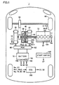
- Vehicle 1 includes an engine 10, a drive shaft 16, a first motor generator (hereinafter referred to as first MG) 20, a second motor generator (hereinafter referred to as second MG) 30, a power split device 40, a speed reducer 58, a PCU (Power Control Unit) 60, a battery 70, drive wheels 80, a start switch 150, and an ECU (Electronic Control Unit) 200.
- first MG first motor generator
- second MG second motor generator
- PCU Power Control Unit
- battery 70 battery 70
- drive wheels 80 drive wheels 80
- start switch 150 a start switch 150
- ECU Electronic Control Unit
- Vehicle 1 travels with driving force output from at least one of engine 10 and second MG 30.
- Motive power generated by engine 10 is split for two paths by power split device 40. Of the two paths, one is a path for transmission via speed reducer 58 to drive wheels 80, and the other is a path for transmission to first MG 20.
- First MG 20 and second MG 30 are, for example, three-phase AC rotating electric machines. First MG 20 and second MG 30 are driven by PCU 60.
- First MG 20 has a function as a generator which generates power using motive power of engine 10 split by power split device 40, to charge battery 70 via PCU 60. In addition, receiving power from battery 70, first MG 20 rotates a crankshaft of engine 10 which serves as an output shaft. First MG 20 thereby has a function as a starter which starts engine 10.
- Second MG 30 has a function as a drive motor which provides driving force for drive wheels 80 using at least any one of power stored in battery 70 and power generated by first MG 20.
- second MG 30 has a function as a generator for charging battery 70 via PCU 60 with the use of power generated through regenerative braking.
- Engine 10 is, for example, an internal combustion engine such as a gasoline engine and a diesel engine.
- Engine 10 includes a plurality of cylinders 102 and a fuel injection device 104 which supplies fuel to each of the plurality of cylinders 102. Based on a control signal S1 from ECU 200, fuel injection device 104 injects an appropriate amount of fuel for each cylinder with appropriate timing and stops injecting fuel for each cylinder.
- engine 10 For the detection of the rotational speed of the crankshaft of engine 10 (hereinafter referred to as engine rotational speed) Ne, engine 10 is further provided with an engine rotational speed sensor 11.
- Engine rotational speed sensor 11 transmits a signal indicating detected engine rotational speed Ne to ECU 200.
- Power split device 40 mechanically couples together three elements for rotating drive wheels 80: drive shaft 16, the output shaft of engine 10, and a rotation shaft of first MG 20. Power split device 40 utilizes any one of the above-indicated three elements as a reaction force element, thereby allowing for the transfer of motive power between the other two elements. A rotation shaft of second MG 30 is coupled to drive shaft 16.
- Power split device 40 is a planetary gear mechanism including a sun gear 50, pinion gears 52, a carrier 54, and a ring gear 56.
- Pinion gear 52 engages with each of sun gear 50 and ring gear 56.
- Carrier 54 supports pinion gears 52 in a manner to allow them to rotate, and is coupled to a crankshaft of engine 10.
- Sun gear 50 is coupled to the rotation shaft of first MG 20.
- Ring gear 56 is coupled via drive shaft 16 to the rotation shaft of second MG 30 and speed reducer 58.
- Speed reducer 58 transfers motive power from power split device 40 and second MG 30 to drive wheels 80. In addition, speed reducer 58 transfers reaction force received by drive wheels 80 from a road surface, to power split device 40 and second MG 30.
- PCU 60 converts DC power stored in battery 70 into AC power for driving first MG 20 and second MG 30.
- PCU 60 includes a converter and an inverter (both not shown) which are controlled based on a control signal S2 from ECU 200.
- the converter boosts a voltage of DC power received from battery 70 and outputs the boosted power to the inverter.
- the inverter converts the DC power output from the converter into AC power for output to first MG 20 and/or second MG 30.
- First MG 20 and/or second MG 30 are thus driven by using the power stored in battery 70.
- the inverter converts AC power generated by first MG 20 and/or second MG 30 into DC power and outputs it to the converter.
- the converter steps down a voltage of the DC power output by the inverter and outputs the stepped down power to battery 70.
- Battery 70 is thereby charged with the use of the power generated by first MG 20 and/or second MG 30. It is noted that the converter may be omitted.
- Battery 70 is a power storage device and a rechargeable DC power supply.
- a secondary battery such as a nickel-metal hydride secondary battery and a lithium ion secondary battery is used.
- Battery 70 has a voltage of the order of 200 V, for example.
- Battery 70 may be charged, other than with the use of the power generated by first MG 20 and/or second MG 30 as described above, with the use of power supplied from an external power supply (not shown). It is noted that battery 70 is not limited to a secondary battery, and may be anything that can generate a DC voltage, such as a capacitor, a solar cell, and a fuel cell, for example.
- Battery 70 is provided with a battery temperature sensor 156 for detecting a battery temperature TB of battery 70, a current sensor 158 for detecting a current IB of battery 70, and a voltage sensor 160 for detecting a voltage VB of battery 70.
- Battery temperature sensor 156 transmits a signal indicating battery temperature TB to ECU 200.
- Current sensor 158 transmits a signal indicating current IB to ECU 200.
- Voltage sensor 160 transmits a signal indicating voltage VB to ECU 200.
- Start switch 150 is, for example, a push switch. Start switch 150 may be one that allows a key to be inserted into a key cylinder and rotated to a prescribed position. Start switch 150 is connected to ECU 200. In response to an operation of start switch 150 by a driver, start switch 150 transmits a signal ST to ECU 200.
- ECU 200 determines that a start command has been received when, for example, signal ST has been received while the system of vehicle 1 is in a stop state, and then ECU 200 shifts the system of vehicle 1 from the stop state to a startup state. In addition, ECU 200 determines that a stop command has been received when signal ST has been received while the system of vehicle 1 is in the startup state, and then ECU 200 shifts the system of vehicle 1 from the startup state to the stop state.
- operation of start switch 150 by the driver when the system of vehicle 1 is in the startup state will be referred to as an IG OFF operation
- operation of start switch 150 by the driver when the system of vehicle 1 is in the stop state will be referred to as an IG ON operation.
- a first resolver 12 detects rotational speed Nm1 of first MG 20.
- First resolver 12 transmits a signal indicating detected rotational speed Nm1 to ECU 200.
- a second resolver 13 detects rotational speed Nm2 of second MG 30.
- Second resolver 13 transmits a signal indicating detected rotational speed Nm2 to ECU 200.
- a wheel speed sensor 14 detects rotational speed Nw of drive wheels 80. Wheel speed sensor 14 transmits a signal indicating detected rotational speed Nw to ECU 200. ECU 200 calculates vehicle speed V based on rotational speed Nw received. It is noted that ECU 200 may calculate vehicle speed V based on rotational speed Nm2 of second MG 30 instead of rotational speed Nw.
- ECU 200 generates control signal S1 for controlling engine 10 and outputs generated control signal S1 to engine 10. Further, ECU 200 generates control signal S2 for controlling PCU 60 and outputs generated control signal S2 to PCU 60.
- ECU 200 controls the entire hybrid system, that is, a state of charging/discharging of battery 70 and states of operation of engine 10, first MG 20 and second MG 30 such that vehicle 1 can travel most efficiently.
- ECU 200 calculates requested driving force which corresponds to an amount of depression of an accelerator pedal (not shown) provided at a driver's seat. ECU 200 controls torque of first MG 20 and second MG 30, and an output of engine 10, in accordance with the calculated requested driving force.
- Vehicle 1 having a configuration as described above travels solely on second MG 30 when engine 10 is inefficient at the start of traveling or during low-speed traveling.
- power split device 40 divides motive power of engine 10 into two paths of motive power.
- Motive power in one path directly drives drive wheels 80.
- Motive power in the other path drives first MG 20 to generate power.
- ECU 200 uses generated power to drive second MG 30. In this way, by driving second MG 30, assistance in driving drive wheels 80 is provided.
- ECU 200 may exert control for increasing driving force from engine 10 as necessary, for example, such as when battery 70 is in need of charging as described above, when auxiliary machinery such as an air conditioner is to be driven, and when the temperature of cooling water for engine 10 is to be raised to a prescribed temperature.
- ECU 200 sets, based on battery temperature TB and the current SOC, allowable input power in charging battery 70 (hereinafter referred to as “charge power upper limit value Win”) and allowable output power in discharging battery 70 (hereinafter referred to as “discharge power upper limit value Wout"). For instance, as the current SOC gets lower, discharge power upper limit value Wout is gradually set lower. In contrast, as the current SOC gets higher, charge power upper limit value Win is gradually set lower.
- the secondary battery used as battery 70 has temperature dependence that causes an increase in internal resistance at low temperatures. In addition, at high temperatures, it is necessary to prevent an overincrease in temperature caused by further heat generation. It is therefore preferable to lower each of discharge power upper limit value Wout and charge power upper limit value Win when battery temperature TB is low and when battery temperature TB is high.
- ECU 200 sets charge power upper limit value Win and discharge power upper limit value Wout in accordance with battery temperature TB and the current SOC, for example, through the use of a map or the like.
- vehicle 1 having the configuration described above, if engine 10 has stopped due to some cause during high-speed traveling, the engine cannot in some cases be restarted immediately. It is assumed that vehicle 1 is traveling at high speed, as indicated by the solid line shown in the nomographic chart of Fig. 2 , for example.
- the left vertical axis indicates the rotational speed of sun gear 50, that is, rotational speed Nm1 of first MG 20.
- the center vertical axis of the nomographic chart shown in Fig. 2 indicates the rotational speed of carrier 54, that is, engine rotational speed Ne.
- the right vertical axis of the nomographic chart shown in Fig. 2 indicates the rotational speed of ring gear 56, that is, rotational speed Nm2 of second MG 30. It is noted that the direction of an arrow formed by each vertical axis of the nomographic chart of Fig. 2 indicates a positive rotational direction, and a direction opposite to the direction of the arrow indicates a negative rotational direction.
- rotational speed Nm1 of first MG 20 While vehicle 1 is traveling, rotational speed Nm1 of first MG 20, engine rotational speed Ne, and rotational speed Nm2 of second MG 30 vary in such a manner that rotational speeds Nm1, Ne and Nm2 of these elements maintain such a relation that they are connected by a straight line in the nomographic chart of Fig. 2 .
- rotational speed Nm1 of first MG 20 is Nm1(0)
- engine rotational speed Ne is Ne(0)
- rotational speed Nm2 of second MG 30 is Nm2(0).
- First MG 20 It is thus necessary to generate torque in the positive rotational direction opposite to a rotational direction of first MG 20 (negative rotational direction).
- First MG 20 generates power in the process of elevating the rotational speed of first MG 20 from Nm1(1) to Nm1(0).
- first MG 20 may not be able to generate power. Therefore, the engine cannot in some cases be restarted immediately.
- the present embodiment has a feature in that first MG 20 is controlled to transmit torque of first MG 20 to the output shaft of engine 10 when ECU 200 has received the stop command at start switch 150 while vehicle 1 is traveling, and when a predetermined condition in which the input power is restricted in battery 70 is satisfied.
- FIG. 3 shows a functional block diagram of ECU 200 mounted on vehicle 1 according to the present embodiment.
- ECU 200 includes a determination unit 202, a Win determination unit 204, a fuel-cut control unit 206, and an MG control unit 208.
- Determination unit 202 determines whether the IG OFF operation has been performed or not. Determination unit 202 determines that the IG OFF operation has been performed (the stop command has been received) when signal ST has been received from start switch 150 while the system of vehicle 1 is in the start state. It is noted that determination unit 202 may, for example, turn an IG OFF determination flag on when the IG OFF operation has been performed.
- determination unit 202 determines whether vehicle 1 is traveling or not. Determination unit 202 determines that vehicle 1 is traveling when vehicle speed V is higher than a prescribed vehicle speed V(0). It is noted that determination unit 202 may turn a travel determination flag on when it is determined that vehicle 1 is traveling.
- Win determination unit 204 determines whether the predetermined condition in which the input power is restricted in battery 70 is satisfied or not.
- the predetermined condition is that charge power upper limit value Win is lower than a threshold value Win(0).
- the predetermined condition includes, for example, at least any one of the following conditions: a condition that the SOC of battery 70 is higher than a threshold value SOC(0); a condition that battery temperature TB of battery 70 is lower than a threshold value TB(0); and a condition that a charge duration time Tc of battery 70 immediately before is longer than a prescribed time Tc(0).
- Win determination unit 204 estimates the SOC based on battery temperature TB, current IB and voltage VB. For example, Win determination unit 204 estimates an internal resistance having a characteristic dependent on battery temperature TB, based on battery temperature TB. Win determination unit 204 estimates an open circuit voltage (OCV) from the estimated internal resistance, current IB and voltage VB. Win determination unit 204 estimates the SOC based on the estimated open circuit voltage. It is noted that the above-described method of estimating the SOC is merely by way of example, and any other known technique may be used to estimate the SOC of battery 70.
- Win determination unit 204 may determine whether the predetermined condition is satisfied or not when, for example, both the IG OFF determination flag and the travel determination flag are in the ON state. Win determination unit 204 may also turn the Win determination flag on when the predetermined condition is satisfied.
- fuel-cut control unit 206 executes fuel-cut control to stop fuel injection to cylinders 102.
- Fuel-cut control unit 206 generates control signal S1 indicating the execution of the fuel-cut control, and transmits generated control signal S1 to engine 10. It is noted that fuel-cut control unit 206 may execute the fuel-cut control when, for example, both the IG OFF determination flag and the travel determination flag are in the ON state. Fuel-cut control unit 206 may also stop the fuel injection to cylinders 102 by not transmitting control signal S1 to engine 10.
- MG control unit 208 controls first MG 20 and second MG 30 to transmit torque of first MG 20 to the output shaft of engine 10 when Win determination unit 204 has determined that the predetermined condition has been satisfied.
- MG control unit 208 controls first MG 20 and second MG 30 such that first MG 20 generates positive torque in the positive rotational direction, in order to consume power in first MG 20.
- MG control unit 208 controls first MG 20 such that the power consumed in first MG 20 increases as the degree of restriction of the input power in battery 70 increases.
- MG control unit 208 controls first MG 20 such that the power consumed in first MG 20 increases as a difference between the SOC and threshold value SOC(0) increases.
- MG control unit 208 controls first MG 20 such that the power consumed in first MG 20 increases as a difference between battery temperature TB and threshold value TB(0) increases.
- MG control unit 208 controls first MG 20 such that the power consumed in first MG 20 increases as a difference between charge duration time Tc and prescribed time Tc(0) increases.
- MG control unit 208 increases the power consumption by increasing the torque generated in first MG 20. That is, MG control unit 208 determines a torque command value Treq1 of first MG 20 in accordance with charge power upper limit value Win. For example, when charge power upper limit value Win is lower than threshold value Win(0), MG control unit 208 determines torque command value Treq1 of first MG 20 such that the torque generated in first MG 20 increases as charge power upper limit value Win decreases.
- MG control unit 208 controls second MG 30 to generate reaction force torque against the torque of first MG 20. This is because when the torque in the positive rotational direction is generated in first MG 20, the torque generated in first MG 20 causes torque in the negative rotational direction to be generated in second MG 30, which causes vehicle 1 to be rapidly decelerated. The reaction force torque can be reduced by MG control unit 208 causing second MG 30 to generate the torque in the positive rotational direction. It is noted that MG control unit 208 may determine a torque command value Treq2 of second MG 30 such that torque corresponding to the reaction force torque is generated in second MG 30.
- MG control unit 208 may determine torque command value Treq2 of second MG 30 such that torque less than the torque corresponding to the reaction force torque is generated in second MG 30.
- MG control unit 208 may determine torque command value Treq2 such that deceleration of vehicle 1 becomes lower than a threshold value, for example.
- the threshold value of deceleration is for determining whether a shock perceptible by the driver occurs in vehicle 1 due to large deceleration or not.
- MG control unit 208 may continue controlling first MG 20 and second MG 30 until vehicle 1 stops or may continue controlling first MG 20 and second MG 30 until the 1G ON operation is performed by the driver.
- MG control unit 208 may control first MG 20 and second MG 30 to transmit the torque of first MG 20 to the output shaft of engine 10.
- determination unit 202 Win determination unit 204, fuel-cut control unit 206, and MG control unit 208 are described in the present embodiment as realized through execution of a program stored in a memory by a CPU of ECU 200 and as functioning as software, they may be realized by hardware. It is noted that such a program is recorded in a storage medium for installation in the vehicle.
- step (“step” will hereinafter be denoted as "S") 100, ECU 200 determines whether the IG OFF operation has been performed or not. If the IG OFF operation has been performed (YES in S100), the process is transferred to S102. If not (NO in S100), the process is returned to S100.
- ECU 200 determines whether vehicle 1 is traveling or not. ECU 200 determines that vehicle 1 is traveling when vehicle speed V of vehicle 1 is equal to or higher than prescribed vehicle speed V(0). If vehicle 1 is traveling (YES in S102), the process is transferred to S104. If not (NO in S102), the process is returned to S100.
- ECU 200 executes the fuel-cut control.
- ECU 200 determines whether Win is reduced or not. That is, when the predetermined condition is satisfied, ECU 200 determines that Win is reduced. If charge power upper limit value Win is reduced (YES in S106), the process is transferred to S108. If not (NO in S106), the process ends.
- ECU200 determines torque command value Treq1 of first MG 20 in accordance with charge power upper limit value Win, and determines torque command value Treq2 of second MG 30 based on determined torque command value Treq1 of first MG 20. Since the method of determining torque command values Treq1 and Treq2 is as described above, detailed description thereof will not be repeated.
- first MG 20 is controlled to generate torque in accordance with determined torque command value Treq1.
- second MG 30 is controlled to generate torque in accordance with determined torque command value Treq2.
- rotational speed Nm1 of first MG 20 is Nm1(1) (positive rotational direction)
- engine rotational speed Ne is Ne(1)
- rotational speed Nm2 of second MG 30 is Nm2(1).
- the fuel-cut control is executed (S104). If charge power upper limit value Win is reduced in battery 70 (YES in S 106), torque command value Treq1 of first MG 20 corresponding to charge power upper limit value Win is determined, and torque command value Treq2 of second MG 30 is determined based on determined torque command value Treq1 of first MG 20 (S 108). First MG 20 and second MG 30 are then controlled based on determined torque command values Treq1 and Treq2 (S110, S 112).
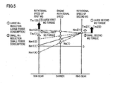
- Torque Tm1(0) (the (black) arrows in Fig. 5 ) generated in first MG 20 when the predetermined condition is satisfied and when an amount of reduction in charge power upper limit value Win is large (hereinafter simply described as “in the case of a large reduction") is greater than torque Tm1(1) generated in first MG 20 when the amount of reduction in charge power upper limit value Win is small (hereinafter simply described as “in the case of a small reduction”).
- rotational speed Nm1(2) of first MG 20 in the case of a large reduction is higher than rotational speed Nm1(3) of first MG 20 in the case of a small reduction. Therefore, power consumption (rotational speed x torque) in first MG 20 in the case of a large reduction is greater than power consumption in first MG 20 in the case of a small reduction.
- Torque Tm2(0) (the (black) arrows in Fig. 5 ) generated in second MG 30 in the case of a large reduction is greater than torque Tm2(1) generated in second MG 30 in the case of a small reduction. Since the torque generated in second MG 30 is thus determined in accordance with the torque generated in first MG 20, rapid deceleration of vehicle 1 is suppressed.
- the SOC of battery 70 is lowered by power consumption in first MG 20. Furthermore, since stopping of rotation of the output shaft of engine 10 is suppressed by driving first MG 20, engine 10 can be started immediately in response to a request for restarting the engine, such as the IG ON operation performed by the driver. In this case, engine 10 is started without generating power because first MG 20 is rotating in the positive rotational direction.
- the SOC of battery 70 can be lowered by consuming power in first MG 20 when the IG OFF operation is performed during traveling and when the predetermined condition in which the input power is restricted in battery 70 is satisfied.
- the degree of restriction when charge power upper limit value Win is restricted due to the SOC being high can be alleviated.
- the engine can be started without generating power in first MG 20 when engine 10 is started by the IG ON operation performed by the driver.
- the power generated at the time of start can be absorbed into battery 70 by consuming the power in power storage device 70 in advance.
- engine 10 can be started immediately in response to the driver's request.
- a vehicle and a control method for a vehicle wherein an engine is controlled to be in a restartable state when a stop command for the engine has been received during high-speed traveling. Furthermore, charging of battery 70 over charge power upper limit value Win when engine 10 is started can be avoided. Thus, deterioration of battery 70 can be prevented.
- first MG 20 is rotating in the negative rotational direction, which may cause first MG 20 to generate power by generating torque in the positive rotational direction.
- ECU 200 may control first MG 20 such that prior to executing the fuel-cut control of engine 10, for example, vehicle 1 is decelerated with a braking device or the like, and the torque of first MG 20 is transmitted to engine 10 at the time point when first MG 20 has started rotating in the positive rotational direction.
- ECU 200 may cause the rotational speed of first MG 20 to move in the positive rotational direction while maintaining a balance of power of first MG 20 and second MG 30 at zero.
- ECU 200 controls, for example, first MG 20 and second MG 30 such that the generated power is consumed in second MG 30 during a time period until rotational speed Nm1 of first MG 20 becomes zero.
- first MG 20 rotating in the negative rotational direction can be rotated in the positive rotational direction without burdening battery 70.
- ECU 200 may control first MG 20 such that the fuel-cut control of engine 10 is executed and the torque of first MG 20 is transmitted to engine 10 at the time point when first MG 20 has started rotating in the positive rotational direction.
- ECU 200 control first MG 20 such that, when the torque of first MG 20 is transmitted to engine 10, engine rotational speed Ne reaches a target value.
- a target value a rotational speed that is equal to or higher than the rotational speed at which first explosion can occur, engine 10 can be started immediately when the IG ON operation is performed by the driver.
- control of the first MG is not executed when Win is not reduced. In this way, an increase in the amount of power consumption can be suppressed and deterioration of fuel efficiency can be suppressed.
- ECU 200 may determine that the predetermined condition in which the input power is restricted in battery 70 is satisfied when charge power upper limit value Win is lower than threshold value Win(0). Furthermore, ECU 200 may control first MG 20 such that, when charge power upper limit value Win is lower than threshold value Win(0), for example, the power consumed in first MG 20 increases as a difference between charge power upper limit value Win and threshold value Win(0) increases. MG control unit 208 may control first MG 20 such that, when charge power upper limit value Win is lower than threshold value Win(0), the power consumed where charge power upper limit value Win is a first value becomes greater than the power consumed where charge power upper limit value Win is a second value higher than the first value.
- ECU 200 may control first MG 20 such that, when the predetermined condition is satisfied, the power consumed where the SOC has a first value becomes greater than the power consumed where the SOC has a second value (> SOC(0)) lower than the first value.
- ECU 200 may control first MG 20 such that, when the predetermined condition is satisfied, the power consumed where battery temperature TB has a first value becomes greater than the power consumed where the battery temperature has a second value ( ⁇ TB(0)) higher than the first value.
- ECU 200 may control first MG 20 such that, when the predetermined condition is satisfied, the power consumed where charge duration time Tc lasts for a first period becomes greater than the power consumed where charge duration time Tc lasts for a second period (> Tc(0)) shorter than the first period.
- ECU 200 may cause the power consumption to change in proportion to a difference between an actual value and the threshold value, or may cause the power consumption to change gradually in accordance with a difference between the actual value and the threshold value.
- Fig. 1 shows vehicle 1 having drive wheels 80 as front wheels by way of example
- vehicle 1 may have the drive wheels as rear wheels.
- vehicle 1 may be a vehicle in which second MG 30 in Fig. 1 is omitted.
- vehicle 1 may be a vehicle in which second MG 30 in Fig. 1 is coupled to a drive shaft for driving the rear wheels, instead of being coupled to drive shaft 16 of the front wheels.
- a speed change mechanism may be provided between drive shaft 16 and speed reducer 58 or between drive shaft 16 and second MG 30.
- ECU 200 has been described as being a single ECU in Fig. 1 , two or more ECUs may be used.
- the operation of ECU 200 in Fig. 1 may be shared by an engine ECU for controlling engine 10 and a hybrid ECU for controlling PCU 60.
Landscapes
- Engineering & Computer Science (AREA)
- Chemical & Material Sciences (AREA)
- Combustion & Propulsion (AREA)
- Transportation (AREA)
- Mechanical Engineering (AREA)
- Automation & Control Theory (AREA)
- Hybrid Electric Vehicles (AREA)
- Electric Propulsion And Braking For Vehicles (AREA)
- Combined Controls Of Internal Combustion Engines (AREA)
Abstract
Description
- The present invention relates to control of a vehicle having a rotating electric machine and an internal combustion engine.
- Japanese Patent Laying-Open No.
2007-23919 - In addition, in recent years, as one of the countermeasures against environmental problems, hybrid vehicles equipped with a motor generator and an engine have received attention. A publicly known example of such a hybrid vehicle is a vehicle with elements: drive wheels, an engine, and a motor generator which are mechanically coupled together.
-
- PTD 1: Japanese Patent Laying-Open No.
2007-23919 - In the hybrid vehicle as described above, if the engine has stopped due to some cause while the vehicle is traveling at high speed, the engine cannot in some cases be restarted immediately. This is because when the engine is started using a motor generator while the vehicle is traveling, the motor generator may in some cases generate power. Since power generation is restricted if charging is not permitted due to the state of charge of a power storage device being high, for example, the engine cannot sometimes be restarted immediately.
- With the engine start control system disclosed in the above-described publication, such a problem is not considered at all, and thus cannot be solved.
- An object of the present invention is to provide a vehicle and a control method for a vehicle wherein an engine is controlled to be in a restartable state upon reception of a stop command for the engine during traveling at high speed.
- A vehicle according to one aspect of the present invention includes: a drive shaft for causing a drive wheel to rotate; an internal combustion engine; a first rotating electric machine; a power storage device for supplying and receiving power to and from the first rotating electric machine; a power transmission device mechanically coupling three elements, which are the drive shaft, an output shaft of the internal combustion engine, and a rotation shaft of the first rotating electric machine, the power transmission device utilizing any one of the three elements as a reaction force element, thereby allowing for transmission of motive power between the other two elements; an input unit for receiving a stop command for a system of a vehicle from a driver; and a control unit for controlling the first rotating electric machine such that torque of the first rotating electric machine is transmitted to the output shaft of the internal combustion engine, when the stop command has been received at the input unit while the vehicle is traveling, and when a predetermined condition in which input power is restricted in the power storage device is satisfied.
- Preferably, the first rotating electric machine generates power when the internal combustion engine in a stopped state is started while the vehicle is traveling.
- More preferably, the control unit controls the internal combustion engine to stop fuel injection to the internal combustion engine when the stop command has been received at the input unit while the vehicle is traveling.
- Still more preferably, the control unit controls the first rotating electric machine such that power consumed in the first rotating electric machine increases as a degree of restriction of the input power increases, when the stop command has been received at the input unit while the vehicle is traveling, and when the predetermined condition is satisfied.
- Even more preferably, the predetermined condition includes a condition that a state of charge of the power storage device is higher than a threshold value.
- Still more preferably, the predetermined condition includes a condition that a temperature of the power storage device is lower than a threshold value.
- Even more preferably, the predetermined condition includes a condition that a charge duration time of the power storage device exceeds a prescribed time.
- Still more preferably, the vehicle further includes a second rotating electric machine of which rotation shaft is coupled to the drive shaft. The control unit controls the second rotating electric machine such that reaction force against the torque of the first rotating electric machine is generated, when the stop command has been received at the input unit while the vehicle is traveling, and when the predetermined condition is satisfied.
- Even more preferably, the power transmission device is a planetary gear mechanism having a sun gear, a pinion gear, a carrier, and a ring gear. The sun gear is coupled to the rotation shaft of the first rotating electric machine. The carrier is coupled to the output shaft of the internal combustion engine. The ring gear is coupled to the drive shaft.
- A control method for a vehicle according to another aspect of the present invention is a control method for a vehicle used in a vehicle including a drive shaft for causing a drive wheel to rotate, an internal combustion engine, a rotating electric machine, a power storage device for supplying and receiving power to and from the rotating electric machine, and a power transmission device mechanically coupling three elements, which are the drive shaft, an output shaft of the internal combustion engine, and a rotation shaft of the rotating electric machine, the power transmission device utilizing any one of the three elements as a reaction force element, thereby allowing for transmission of motive power between the other two elements. The control method for a vehicle includes the steps of: determining whether a stop command for a system of the vehicle has been received from a driver or not; and controlling the vehicle such that torque of the rotating electric machine is transmitted to the output shaft of the internal combustion engine, when the stop command has been received while the vehicle is traveling, and when a predetermined condition in which input power is restricted in the power storage device is satisfied.
- According to the present invention, the power can be consumed in the first rotating electric machine, by controlling the vehicle such that the torque of the first rotating electric machine is transmitted to the internal combustion engine when the predetermined condition in which the input power is restricted in the power storage device is satisfied. The state of charge of the power storage device can be reduced by causing the power to be consumed in the first rotating electric machine. As a result, when the input power is restricted due to the state of charge being high, the degree of restriction can be alleviated. Therefore, the power generated through power generation by the first rotating electric machine can be absorbed into the power storage device. Furthermore, when reduction in the rotational speed of the internal combustion engine is suppressed, even if the IG ON operation is subsequently performed by the driver to cause the internal combustion engine to be started using the first rotating electric machine, the internal combustion engine can be started without generating power in the first rotating electric machine. In this way, the internal combustion engine can be started immediately in response to the driver's request. Thus, there can be provided a vehicle and a control method for a vehicle wherein an engine is controlled to be in a restartable state when a stop command for the engine has been received during high-speed traveling.
-
-
Fig. 1 is an overall block diagram of a vehicle according to the present embodiment. -
Fig. 2 is a (first) nomographic chart for illustrating operation of the vehicle in the present embodiment. -
Fig. 3 is a functional block diagram of an ECU mounted on the vehicle according to the present embodiment. -
Fig. 4 is a flowchart of a program executed by the ECU mounted on the vehicle according to the present embodiment. -
Fig. 5 is a (second) nomographic chart for illustrating operation of the vehicle in the present embodiment. - Embodiments of the present invention will be described hereinafter, with reference to the drawings. In the following description, the same components are denoted by the same symbols. The names and functions thereof are also the same. Accordingly, detailed description thereof will not be repeated.
- Referring to
Fig. 1 , an overall block diagram of avehicle 1 according to the present embodiment will be described.Vehicle 1 includes anengine 10, adrive shaft 16, a first motor generator (hereinafter referred to as first MG) 20, a second motor generator (hereinafter referred to as second MG) 30, apower split device 40, aspeed reducer 58, a PCU (Power Control Unit) 60, abattery 70,drive wheels 80, astart switch 150, and an ECU (Electronic Control Unit) 200. -
Vehicle 1 travels with driving force output from at least one ofengine 10 and second MG 30. Motive power generated byengine 10 is split for two paths bypower split device 40. Of the two paths, one is a path for transmission viaspeed reducer 58 to drivewheels 80, and the other is a path for transmission to first MG 20. - First MG 20 and second MG 30 are, for example, three-phase AC rotating electric machines. First MG 20 and second MG 30 are driven by PCU 60.
- First MG 20 has a function as a generator which generates power using motive power of
engine 10 split bypower split device 40, to chargebattery 70 via PCU 60. In addition, receiving power frombattery 70, first MG 20 rotates a crankshaft ofengine 10 which serves as an output shaft. First MG 20 thereby has a function as a starter which startsengine 10. - Second MG 30 has a function as a drive motor which provides driving force for
drive wheels 80 using at least any one of power stored inbattery 70 and power generated by first MG 20. In addition, second MG 30 has a function as a generator forcharging battery 70 via PCU 60 with the use of power generated through regenerative braking. -
Engine 10 is, for example, an internal combustion engine such as a gasoline engine and a diesel engine.Engine 10 includes a plurality ofcylinders 102 and afuel injection device 104 which supplies fuel to each of the plurality ofcylinders 102. Based on a control signal S1 from ECU 200,fuel injection device 104 injects an appropriate amount of fuel for each cylinder with appropriate timing and stops injecting fuel for each cylinder. - For the detection of the rotational speed of the crankshaft of engine 10 (hereinafter referred to as engine rotational speed) Ne,
engine 10 is further provided with an enginerotational speed sensor 11. Enginerotational speed sensor 11 transmits a signal indicating detected engine rotational speed Ne toECU 200. - Power split
device 40 mechanically couples together three elements for rotating drive wheels 80: driveshaft 16, the output shaft ofengine 10, and a rotation shaft offirst MG 20. Power splitdevice 40 utilizes any one of the above-indicated three elements as a reaction force element, thereby allowing for the transfer of motive power between the other two elements. A rotation shaft ofsecond MG 30 is coupled to driveshaft 16. - Power split
device 40 is a planetary gear mechanism including asun gear 50, pinion gears 52, acarrier 54, and aring gear 56.Pinion gear 52 engages with each ofsun gear 50 andring gear 56.Carrier 54 supports pinion gears 52 in a manner to allow them to rotate, and is coupled to a crankshaft ofengine 10.Sun gear 50 is coupled to the rotation shaft offirst MG 20.Ring gear 56 is coupled viadrive shaft 16 to the rotation shaft ofsecond MG 30 andspeed reducer 58. -
Speed reducer 58 transfers motive power frompower split device 40 andsecond MG 30 to drivewheels 80. In addition,speed reducer 58 transfers reaction force received bydrive wheels 80 from a road surface, topower split device 40 andsecond MG 30. -
PCU 60 converts DC power stored inbattery 70 into AC power for drivingfirst MG 20 andsecond MG 30.PCU 60 includes a converter and an inverter (both not shown) which are controlled based on a control signal S2 fromECU 200. The converter boosts a voltage of DC power received frombattery 70 and outputs the boosted power to the inverter. The inverter converts the DC power output from the converter into AC power for output tofirst MG 20 and/orsecond MG 30.First MG 20 and/orsecond MG 30 are thus driven by using the power stored inbattery 70. In addition, the inverter converts AC power generated byfirst MG 20 and/orsecond MG 30 into DC power and outputs it to the converter. The converter steps down a voltage of the DC power output by the inverter and outputs the stepped down power tobattery 70.Battery 70 is thereby charged with the use of the power generated byfirst MG 20 and/orsecond MG 30. It is noted that the converter may be omitted. -
Battery 70 is a power storage device and a rechargeable DC power supply. Asbattery 70, for example, a secondary battery such as a nickel-metal hydride secondary battery and a lithium ion secondary battery is used.Battery 70 has a voltage of the order of 200 V, for example.Battery 70 may be charged, other than with the use of the power generated byfirst MG 20 and/orsecond MG 30 as described above, with the use of power supplied from an external power supply (not shown). It is noted thatbattery 70 is not limited to a secondary battery, and may be anything that can generate a DC voltage, such as a capacitor, a solar cell, and a fuel cell, for example. -
Battery 70 is provided with abattery temperature sensor 156 for detecting a battery temperature TB ofbattery 70, acurrent sensor 158 for detecting a current IB ofbattery 70, and avoltage sensor 160 for detecting a voltage VB ofbattery 70. -
Battery temperature sensor 156 transmits a signal indicating battery temperature TB toECU 200.Current sensor 158 transmits a signal indicating current IB toECU 200.Voltage sensor 160 transmits a signal indicating voltage VB toECU 200. -
Start switch 150 is, for example, a push switch.Start switch 150 may be one that allows a key to be inserted into a key cylinder and rotated to a prescribed position.Start switch 150 is connected toECU 200. In response to an operation ofstart switch 150 by a driver, startswitch 150 transmits a signal ST toECU 200. -
ECU 200 determines that a start command has been received when, for example, signal ST has been received while the system ofvehicle 1 is in a stop state, and thenECU 200 shifts the system ofvehicle 1 from the stop state to a startup state. In addition,ECU 200 determines that a stop command has been received when signal ST has been received while the system ofvehicle 1 is in the startup state, and thenECU 200 shifts the system ofvehicle 1 from the startup state to the stop state. In the following descriptions, operation ofstart switch 150 by the driver when the system ofvehicle 1 is in the startup state will be referred to as an IG OFF operation, and operation ofstart switch 150 by the driver when the system ofvehicle 1 is in the stop state will be referred to as an IG ON operation. Once the system ofvehicle 1 shifts to the startup state, for example, a plurality of pieces of equipment necessary forvehicle 1 to travel are supplied with power, and then enter an operable state. In contrast, once the system ofvehicle 1 shifts to the stop state, for example, part of the plurality of pieces of equipment necessary forvehicle 1 to travel are no longer supplied with power, and then enter an operation stop state. - A
first resolver 12 detects rotational speed Nm1 offirst MG 20.First resolver 12 transmits a signal indicating detected rotational speed Nm1 toECU 200. Asecond resolver 13 detects rotational speed Nm2 ofsecond MG 30.Second resolver 13 transmits a signal indicating detected rotational speed Nm2 toECU 200. - A wheel speed sensor 14 detects rotational speed Nw of
drive wheels 80. Wheel speed sensor 14 transmits a signal indicating detected rotational speed Nw toECU 200.ECU 200 calculates vehicle speed V based on rotational speed Nw received. It is noted thatECU 200 may calculate vehicle speed V based on rotational speed Nm2 ofsecond MG 30 instead of rotational speed Nw. -
ECU 200 generates control signal S1 for controllingengine 10 and outputs generated control signal S1 toengine 10. Further,ECU 200 generates control signal S2 for controllingPCU 60 and outputs generated control signal S2 toPCU 60. - By controlling
engine 10,PCU 60, and the like,ECU 200 controls the entire hybrid system, that is, a state of charging/discharging ofbattery 70 and states of operation ofengine 10,first MG 20 andsecond MG 30 such thatvehicle 1 can travel most efficiently. -
ECU 200 calculates requested driving force which corresponds to an amount of depression of an accelerator pedal (not shown) provided at a driver's seat.ECU 200 controls torque offirst MG 20 andsecond MG 30, and an output ofengine 10, in accordance with the calculated requested driving force. -
Vehicle 1 having a configuration as described above travels solely onsecond MG 30 whenengine 10 is inefficient at the start of traveling or during low-speed traveling. In addition, during normal traveling, for example, power splitdevice 40 divides motive power ofengine 10 into two paths of motive power. Motive power in one path directly drivesdrive wheels 80. Motive power in the other path drivesfirst MG 20 to generate power. At this time,ECU 200 uses generated power to drivesecond MG 30. In this way, by drivingsecond MG 30, assistance in drivingdrive wheels 80 is provided. - When
vehicle 1 reduces its speed, regenerative braking is performed withsecond MG 30, which follows the rotation ofdrive wheels 80, functioning as a generator. The power recovered through regenerative braking is stored inbattery 70. It is noted that when remaining capacitance (hereinafter referred to as SOC (State of Charge)) of the power storage device has lowered and is particularly in need of charging,ECU 200 increases an output ofengine 10 to increase an amount of power generated byfirst MG 20. The SOC ofbattery 70 is thereby increased. In addition, even during low-speed traveling,ECU 200 may exert control for increasing driving force fromengine 10 as necessary, for example, such as whenbattery 70 is in need of charging as described above, when auxiliary machinery such as an air conditioner is to be driven, and when the temperature of cooling water forengine 10 is to be raised to a prescribed temperature. - In controlling amounts of charging and discharging of
battery 70,ECU 200 sets, based on battery temperature TB and the current SOC, allowable input power in charging battery 70 (hereinafter referred to as "charge power upper limit value Win") and allowable output power in discharging battery 70 (hereinafter referred to as "discharge power upper limit value Wout"). For instance, as the current SOC gets lower, discharge power upper limit value Wout is gradually set lower. In contrast, as the current SOC gets higher, charge power upper limit value Win is gradually set lower. - In addition, the secondary battery used as
battery 70 has temperature dependence that causes an increase in internal resistance at low temperatures. In addition, at high temperatures, it is necessary to prevent an overincrease in temperature caused by further heat generation. It is therefore preferable to lower each of discharge power upper limit value Wout and charge power upper limit value Win when battery temperature TB is low and when battery temperature TB is high.ECU 200 sets charge power upper limit value Win and discharge power upper limit value Wout in accordance with battery temperature TB and the current SOC, for example, through the use of a map or the like. - In
vehicle 1 having the configuration described above, ifengine 10 has stopped due to some cause during high-speed traveling, the engine cannot in some cases be restarted immediately. It is assumed thatvehicle 1 is traveling at high speed, as indicated by the solid line shown in the nomographic chart ofFig. 2 , for example. - Of the three vertical axes of the nomographic chart shown in
Fig. 2 , the left vertical axis indicates the rotational speed ofsun gear 50, that is, rotational speed Nm1 offirst MG 20. The center vertical axis of the nomographic chart shown inFig. 2 indicates the rotational speed ofcarrier 54, that is, engine rotational speed Ne. The right vertical axis of the nomographic chart shown inFig. 2 indicates the rotational speed ofring gear 56, that is, rotational speed Nm2 ofsecond MG 30. It is noted that the direction of an arrow formed by each vertical axis of the nomographic chart ofFig. 2 indicates a positive rotational direction, and a direction opposite to the direction of the arrow indicates a negative rotational direction. - While
vehicle 1 is traveling, rotational speed Nm1 offirst MG 20, engine rotational speed Ne, and rotational speed Nm2 ofsecond MG 30 vary in such a manner that rotational speeds Nm1, Ne and Nm2 of these elements maintain such a relation that they are connected by a straight line in the nomographic chart ofFig. 2 . - As indicated by the solid line in
Fig. 2 , it is assumed that rotational speed Nm1 offirst MG 20 is Nm1(0), engine rotational speed Ne is Ne(0), and rotational speed Nm2 ofsecond MG 30 is Nm2(0). - If rotation of
engine 10 has stopped when the IG OFF operation is performed whilevehicle 1 is traveling at high speed,vehicle 1 enters a state indicated by the broken line inFig. 2 . It is now assumed thatengine 10 is started usingfirst MG 20. In this case, it is necessary to increase engine rotational speed Ne to be higher than a lowest engine rotational speed at which first explosion can occur, by elevating rotational speed Nm1 offirst MG 20 from Nm1(1) to Nm1(0). - It is thus necessary to generate torque in the positive rotational direction opposite to a rotational direction of first MG 20 (negative rotational direction).
First MG 20, however, generates power in the process of elevating the rotational speed offirst MG 20 from Nm1(1) to Nm1(0). Thus, if charging is restricted due to the SOC ofbattery 70 being higher than a normal SOC range, that is, if charge power upper limit value Win is lower than a case where the SOC is within the normal SOC range,first MG 20 may not be able to generate power. Therefore, the engine cannot in some cases be restarted immediately. - Accordingly, the present embodiment has a feature in that
first MG 20 is controlled to transmit torque offirst MG 20 to the output shaft ofengine 10 whenECU 200 has received the stop command atstart switch 150 whilevehicle 1 is traveling, and when a predetermined condition in which the input power is restricted inbattery 70 is satisfied. -
Fig. 3 shows a functional block diagram ofECU 200 mounted onvehicle 1 according to the present embodiment.ECU 200 includes adetermination unit 202, aWin determination unit 204, a fuel-cut control unit 206, and anMG control unit 208. -
Determination unit 202 determines whether the IG OFF operation has been performed or not.Determination unit 202 determines that the IG OFF operation has been performed (the stop command has been received) when signal ST has been received fromstart switch 150 while the system ofvehicle 1 is in the start state. It is noted thatdetermination unit 202 may, for example, turn an IG OFF determination flag on when the IG OFF operation has been performed. - Further,
determination unit 202 determines whethervehicle 1 is traveling or not.Determination unit 202 determines thatvehicle 1 is traveling when vehicle speed V is higher than a prescribed vehicle speed V(0). It is noted thatdetermination unit 202 may turn a travel determination flag on when it is determined thatvehicle 1 is traveling. - When
determination unit 202 has determined that the IG OFF operation has been performed andvehicle 1 is traveling,Win determination unit 204 determines whether the predetermined condition in which the input power is restricted inbattery 70 is satisfied or not. The predetermined condition is that charge power upper limit value Win is lower than a threshold value Win(0). The predetermined condition includes, for example, at least any one of the following conditions: a condition that the SOC ofbattery 70 is higher than a threshold value SOC(0); a condition that battery temperature TB ofbattery 70 is lower than a threshold value TB(0); and a condition that a charge duration time Tc ofbattery 70 immediately before is longer than a prescribed time Tc(0). - Win
determination unit 204 estimates the SOC based on battery temperature TB, current IB and voltage VB. For example,Win determination unit 204 estimates an internal resistance having a characteristic dependent on battery temperature TB, based on battery temperature TB. Windetermination unit 204 estimates an open circuit voltage (OCV) from the estimated internal resistance, current IB and voltage VB. Windetermination unit 204 estimates the SOC based on the estimated open circuit voltage. It is noted that the above-described method of estimating the SOC is merely by way of example, and any other known technique may be used to estimate the SOC ofbattery 70. - It is noted that
Win determination unit 204 may determine whether the predetermined condition is satisfied or not when, for example, both the IG OFF determination flag and the travel determination flag are in the ON state. Windetermination unit 204 may also turn the Win determination flag on when the predetermined condition is satisfied. - When
determination unit 202 has determined that the IG OFF operation has been performed, and has also determined thatvehicle 1 is traveling, fuel-cut control unit 206 executes fuel-cut control to stop fuel injection tocylinders 102. Fuel-cut control unit 206 generates control signal S1 indicating the execution of the fuel-cut control, and transmits generated control signal S1 toengine 10. It is noted that fuel-cut control unit 206 may execute the fuel-cut control when, for example, both the IG OFF determination flag and the travel determination flag are in the ON state. Fuel-cut control unit 206 may also stop the fuel injection tocylinders 102 by not transmitting control signal S1 toengine 10. -
MG control unit 208 controlsfirst MG 20 andsecond MG 30 to transmit torque offirst MG 20 to the output shaft ofengine 10 whenWin determination unit 204 has determined that the predetermined condition has been satisfied. - When it has been determined that the predetermined condition has been satisfied,
MG control unit 208 controlsfirst MG 20 andsecond MG 30 such thatfirst MG 20 generates positive torque in the positive rotational direction, in order to consume power infirst MG 20. - In the present embodiment,
MG control unit 208 controlsfirst MG 20 such that the power consumed infirst MG 20 increases as the degree of restriction of the input power inbattery 70 increases. - When the predetermined condition is satisfied,
MG control unit 208 controlsfirst MG 20 such that the power consumed infirst MG 20 increases as a difference between the SOC and threshold value SOC(0) increases. - Moreover, when the predetermined condition is satisfied,
MG control unit 208 controlsfirst MG 20 such that the power consumed infirst MG 20 increases as a difference between battery temperature TB and threshold value TB(0) increases. - Furthermore, when the predetermined condition is satisfied,
MG control unit 208 controlsfirst MG 20 such that the power consumed infirst MG 20 increases as a difference between charge duration time Tc and prescribed time Tc(0) increases. -
MG control unit 208 increases the power consumption by increasing the torque generated infirst MG 20. That is,MG control unit 208 determines a torque command value Treq1 offirst MG 20 in accordance with charge power upper limit value Win. For example, when charge power upper limit value Win is lower than threshold value Win(0),MG control unit 208 determines torque command value Treq1 offirst MG 20 such that the torque generated infirst MG 20 increases as charge power upper limit value Win decreases. - Moreover,
MG control unit 208 controlssecond MG 30 to generate reaction force torque against the torque offirst MG 20. This is because when the torque in the positive rotational direction is generated infirst MG 20, the torque generated infirst MG 20 causes torque in the negative rotational direction to be generated insecond MG 30, which causesvehicle 1 to be rapidly decelerated. The reaction force torque can be reduced byMG control unit 208 causingsecond MG 30 to generate the torque in the positive rotational direction. It is noted thatMG control unit 208 may determine a torque command value Treq2 ofsecond MG 30 such that torque corresponding to the reaction force torque is generated insecond MG 30. Alternatively,MG control unit 208 may determine torque command value Treq2 ofsecond MG 30 such that torque less than the torque corresponding to the reaction force torque is generated insecond MG 30.MG control unit 208 may determine torque command value Treq2 such that deceleration ofvehicle 1 becomes lower than a threshold value, for example. The threshold value of deceleration is for determining whether a shock perceptible by the driver occurs invehicle 1 due to large deceleration or not. - Furthermore,
MG control unit 208, for example, may continue controllingfirst MG 20 andsecond MG 30 untilvehicle 1 stops or may continue controllingfirst MG 20 andsecond MG 30 until the 1G ON operation is performed by the driver. - It is noted that when the Win determination flag is in the ON state,
MG control unit 208 may controlfirst MG 20 andsecond MG 30 to transmit the torque offirst MG 20 to the output shaft ofengine 10. - Although
determination unit 202,Win determination unit 204, fuel-cut control unit 206, andMG control unit 208 are described in the present embodiment as realized through execution of a program stored in a memory by a CPU ofECU 200 and as functioning as software, they may be realized by hardware. It is noted that such a program is recorded in a storage medium for installation in the vehicle. - Referring to
Fig. 4 , a control structure of a program executed byECU 200 mounted onvehicle 1 according to the present embodiment will be described. - In step ("step" will hereinafter be denoted as "S") 100,
ECU 200 determines whether the IG OFF operation has been performed or not. If the IG OFF operation has been performed (YES in S100), the process is transferred to S102. If not (NO in S100), the process is returned to S100. - In S102,
ECU 200 determines whethervehicle 1 is traveling or not.ECU 200 determines thatvehicle 1 is traveling when vehicle speed V ofvehicle 1 is equal to or higher than prescribed vehicle speed V(0). Ifvehicle 1 is traveling (YES in S102), the process is transferred to S104. If not (NO in S102), the process is returned to S100. - In
S 104,ECU 200 executes the fuel-cut control. In S106,ECU 200 determines whether Win is reduced or not. That is, when the predetermined condition is satisfied,ECU 200 determines that Win is reduced. If charge power upper limit value Win is reduced (YES in S106), the process is transferred to S108. If not (NO in S106), the process ends. - In S108, ECU200 determines torque command value Treq1 of
first MG 20 in accordance with charge power upper limit value Win, and determines torque command value Treq2 ofsecond MG 30 based on determined torque command value Treq1 offirst MG 20. Since the method of determining torque command values Treq1 and Treq2 is as described above, detailed description thereof will not be repeated. - In S110,
first MG 20 is controlled to generate torque in accordance with determined torque command value Treq1. In S112,second MG 30 is controlled to generate torque in accordance with determined torque command value Treq2. - Operation of
ECU 200 mounted onvehicle 1 according to the present embodiment based on the foregoing structure and flowchart will now be described with reference to the nomographic chart ofFig. 5 . Since the element denoted by each axis in the nomographic chart is the same as that in the nomographic chart ofFig. 2 , detailed description thereof will not be repeated. - As indicated by the solid line in
Fig. 5 , it is assumed that rotational speed Nm1 offirst MG 20 is Nm1(1) (positive rotational direction), engine rotational speed Ne is Ne(1), and rotational speed Nm2 ofsecond MG 30 is Nm2(1). - If the IG OFF operation is performed while
vehicle 1 is traveling at high speed (YES inS 100 and YES in S102), the fuel-cut control is executed (S104). If charge power upper limit value Win is reduced in battery 70 (YES in S 106), torque command value Treq1 offirst MG 20 corresponding to charge power upper limit value Win is determined, and torque command value Treq2 ofsecond MG 30 is determined based on determined torque command value Treq1 of first MG 20 (S 108).First MG 20 andsecond MG 30 are then controlled based on determined torque command values Treq1 and Treq2 (S110, S 112). - Torque Tm1(0) (the (black) arrows in
Fig. 5 ) generated infirst MG 20 when the predetermined condition is satisfied and when an amount of reduction in charge power upper limit value Win is large (hereinafter simply described as "in the case of a large reduction") is greater than torque Tm1(1) generated infirst MG 20 when the amount of reduction in charge power upper limit value Win is small (hereinafter simply described as "in the case of a small reduction"). - Here, rotational speed Nm1(2) of
first MG 20 in the case of a large reduction is higher than rotational speed Nm1(3) offirst MG 20 in the case of a small reduction. Therefore, power consumption (rotational speed x torque) infirst MG 20 in the case of a large reduction is greater than power consumption infirst MG 20 in the case of a small reduction. - Torque Tm2(0) (the (black) arrows in
Fig. 5 ) generated insecond MG 30 in the case of a large reduction is greater than torque Tm2(1) generated insecond MG 30 in the case of a small reduction. Since the torque generated insecond MG 30 is thus determined in accordance with the torque generated infirst MG 20, rapid deceleration ofvehicle 1 is suppressed. - Moreover, the SOC of
battery 70 is lowered by power consumption infirst MG 20. Furthermore, since stopping of rotation of the output shaft ofengine 10 is suppressed by drivingfirst MG 20,engine 10 can be started immediately in response to a request for restarting the engine, such as the IG ON operation performed by the driver. In this case,engine 10 is started without generating power becausefirst MG 20 is rotating in the positive rotational direction. - As described above, with the vehicle according to the present embodiment, the SOC of
battery 70 can be lowered by consuming power infirst MG 20 when the IG OFF operation is performed during traveling and when the predetermined condition in which the input power is restricted inbattery 70 is satisfied. Thus, the degree of restriction when charge power upper limit value Win is restricted due to the SOC being high can be alleviated. Furthermore, since a state wherefirst MG 20 is rotating in the positive rotational direction is maintained, the engine can be started without generating power infirst MG 20 whenengine 10 is started by the IG ON operation performed by the driver. Furthermore, even if power generation occurs infirst MG 20 at the time of start, the power generated at the time of start can be absorbed intobattery 70 by consuming the power inpower storage device 70 in advance. Therefore,engine 10 can be started immediately in response to the driver's request. Thus, there can be provided a vehicle and a control method for a vehicle wherein an engine is controlled to be in a restartable state when a stop command for the engine has been received during high-speed traveling. Furthermore, charging ofbattery 70 over charge power upper limit value Win whenengine 10 is started can be avoided. Thus, deterioration ofbattery 70 can be prevented. - It is noted that if
vehicle 1 is in a state indicated by the two-dot chain line inFig. 5 when the IG OFF operation is performed by the driver during traveling,first MG 20 is rotating in the negative rotational direction, which may causefirst MG 20 to generate power by generating torque in the positive rotational direction. In this case, for example,ECU 200 may controlfirst MG 20 such that prior to executing the fuel-cut control ofengine 10, for example,vehicle 1 is decelerated with a braking device or the like, and the torque offirst MG 20 is transmitted toengine 10 at the time point whenfirst MG 20 has started rotating in the positive rotational direction. - Alternatively,
ECU 200 may cause the rotational speed offirst MG 20 to move in the positive rotational direction while maintaining a balance of power offirst MG 20 andsecond MG 30 at zero.ECU 200 controls, for example,first MG 20 andsecond MG 30 such that the generated power is consumed insecond MG 30 during a time period until rotational speed Nm1 offirst MG 20 becomes zero. In this way,first MG 20 rotating in the negative rotational direction can be rotated in the positive rotational direction without burdeningbattery 70.ECU 200 may controlfirst MG 20 such that the fuel-cut control ofengine 10 is executed and the torque offirst MG 20 is transmitted toengine 10 at the time point whenfirst MG 20 has started rotating in the positive rotational direction. - Preferably, it is desirable that
ECU 200 controlfirst MG 20 such that, when the torque offirst MG 20 is transmitted toengine 10, engine rotational speed Ne reaches a target value. For example, by setting, as the target value, a rotational speed that is equal to or higher than the rotational speed at which first explosion can occur,engine 10 can be started immediately when the IG ON operation is performed by the driver. - Furthermore, in the present embodiment, control of the first MG is not executed when Win is not reduced. In this way, an increase in the amount of power consumption can be suppressed and deterioration of fuel efficiency can be suppressed.
- Moreover,
ECU 200 may determine that the predetermined condition in which the input power is restricted inbattery 70 is satisfied when charge power upper limit value Win is lower than threshold value Win(0). Furthermore,ECU 200 may controlfirst MG 20 such that, when charge power upper limit value Win is lower than threshold value Win(0), for example, the power consumed infirst MG 20 increases as a difference between charge power upper limit value Win and threshold value Win(0) increases.MG control unit 208 may controlfirst MG 20 such that, when charge power upper limit value Win is lower than threshold value Win(0), the power consumed where charge power upper limit value Win is a first value becomes greater than the power consumed where charge power upper limit value Win is a second value higher than the first value. - Moreover,
ECU 200 may controlfirst MG 20 such that, when the predetermined condition is satisfied, the power consumed where the SOC has a first value becomes greater than the power consumed where the SOC has a second value (> SOC(0)) lower than the first value. - Moreover,
ECU 200 may controlfirst MG 20 such that, when the predetermined condition is satisfied, the power consumed where battery temperature TB has a first value becomes greater than the power consumed where the battery temperature has a second value (< TB(0)) higher than the first value. - Furthermore,
ECU 200 may controlfirst MG 20 such that, when the predetermined condition is satisfied, the power consumed where charge duration time Tc lasts for a first period becomes greater than the power consumed where charge duration time Tc lasts for a second period (> Tc(0)) shorter than the first period. - It is noted that when each of various parameters (Win, SOC, battery temperature TB, and charge duration time Tc) exceeds a threshold value,
ECU 200 may cause the power consumption to change in proportion to a difference between an actual value and the threshold value, or may cause the power consumption to change gradually in accordance with a difference between the actual value and the threshold value. - While
Fig. 1 showsvehicle 1 havingdrive wheels 80 as front wheels by way of example, the present invention is not particularly limited to such a drive system. For example,vehicle 1 may have the drive wheels as rear wheels. Alternatively,vehicle 1 may be a vehicle in whichsecond MG 30 inFig. 1 is omitted. Still alternatively,vehicle 1 may be a vehicle in whichsecond MG 30 inFig. 1 is coupled to a drive shaft for driving the rear wheels, instead of being coupled to driveshaft 16 of the front wheels. Moreover, a speed change mechanism may be provided betweendrive shaft 16 andspeed reducer 58 or betweendrive shaft 16 andsecond MG 30. - Furthermore, while
ECU 200 has been described as being a single ECU inFig. 1 , two or more ECUs may be used. For example, the operation ofECU 200 inFig. 1 may be shared by an engine ECU for controllingengine 10 and a hybrid ECU for controllingPCU 60. - It should be understood that the embodiments disclosed herein are illustrative and non-restrictive in every respect. The scope of the present invention is defined by the terms of the claims, rather than the description above, and is intended to include any modifications within the scope and meaning equivalent to the terms of the claims.
- 1 vehicle; 10 engine; 11 engine rotational speed sensor; 12 first resolver; 13 second resolver; 14 wheel speed sensor; 16 drive shaft; 40 power split device; 50 sun gear; 52 pinion gear; 54 carrier; 56 ring gear; 58 speed reducer; 70 battery; 80 drive wheel; 102 cylinder; 104 fuel injection device; 150 start switch; 156 battery temperature sensor; 158 current sensor; 160 voltage sensor; 200 ECU; 202 determination unit; 204 Win determination unit; 206 fuel-cut control unit; 208 MG control unit.
Claims (10)
- A vehicle comprising:a drive shaft (16) for causing a drive wheel (80) to rotate;an internal combustion engine (10);a first rotating electric machine (20);a power storage device (70) for supplying and receiving power to and from said first rotating electric machine (20);a power transmission device (40) mechanically coupling three elements, which are said drive shaft (16), an output shaft of said internal combustion engine (10), and a rotation shaft of said first rotating electric machine (20), said power transmission device (40) utilizing any one of said three elements as a reaction force element, thereby allowing for transmission of motive power between the other two elements;an input unit (150) for receiving a stop command for a system of a vehicle (1) from a driver; anda control unit (200) for controlling said first rotating electric machine (20) such that torque of said first rotating electric machine (20) is transmitted to said output shaft of said internal combustion engine (10), when said stop command has been received at said input unit (150) while said vehicle (1) is traveling, and when a predetermined condition in which input power is restricted in said power storage device (70) is satisfied.
- The vehicle according to claim 1, wherein
said first rotating electric machine (20) generates power when said internal combustion engine (10) in a stopped state is started while said vehicle (1) is traveling. - The vehicle according to claim 1, wherein
said control unit (200) controls said internal combustion engine (10) to stop fuel injection to said internal combustion engine (10) when said stop command has been received at said input unit (150) while said vehicle (1) is traveling. - The vehicle according to claim 1, wherein
said control unit (200) controls said first rotating electric machine (20) such that power consumed in said first rotating electric machine (20) increases as a degree of restriction of said input power increases, when said stop command has been received at said input unit (150) while said vehicle (1) is traveling, and when said predetermined condition is satisfied. - The vehicle according to claim 1, wherein
said predetermined condition includes a condition that a state of charge of said power storage device (70) is higher than a threshold value. - The vehicle according to claim 1, wherein
said predetermined condition includes a condition that a temperature of said power storage device (70) is lower than a threshold value. - The vehicle according to claim 1, wherein
said predetermined condition includes a condition that a charge duration time of said power storage device (70) exceeds a prescribed time. - The vehicle according to claim 1, wherein
said vehicle (1) further includes a second rotating electric machine (30) of which rotation shaft is coupled to said drive shaft (16), and
said control unit (200) controls said second rotating electric machine (30) such that reaction force against said torque of said first rotating electric machine (20) is generated, when said stop command has been received at said input unit (150) while said vehicle (1) is traveling, and when said predetermined condition is satisfied. - The vehicle according to any one of claims 1 to 8, wherein
said power transmission device (40) is a planetary gear mechanism having a sun gear (50), a pinion gear (52), a carrier (54), and a ring gear (56),
said sun gear (50) is coupled to said rotation shaft of said first rotating electric machine (20),
said carrier (54) is coupled to said output shaft of said internal combustion engine (10), and
said ring gear (56) is coupled to said drive shaft (16). - A control method for a vehicle used in a vehicle (1) including a drive shaft (16) for causing a drive wheel (80) to rotate, an internal combustion engine (10), a rotating electric machine (20), a power storage device (70) for supplying and receiving power to and from said rotating electric machine (20), and a power transmission device (40) mechanically coupling three elements, which are said drive shaft (16), an output shaft of said internal combustion engine (10), and a rotation shaft of said rotating electric machine (20), said power transmission device (40) utilizing any one of said three elements as a reaction force element, thereby allowing for transmission of motive power between the other two elements, said control method comprising the steps of:determining whether a stop command for a system of said vehicle (1) has been received from a driver or not; andcontrolling said vehicle (1) such that torque of said rotating electric machine (20) is transmitted to said output shaft of said internal combustion engine (10), when said stop command has been received while said vehicle (1) is traveling, and when a predetermined condition in which input power is restricted in said power storage device (70) is satisfied.
Applications Claiming Priority (1)
| Application Number | Priority Date | Filing Date | Title |
|---|---|---|---|
| PCT/JP2011/051557 WO2012101796A1 (en) | 2011-01-27 | 2011-01-27 | Vehicle, and vehicle control method |
Publications (3)
| Publication Number | Publication Date |
|---|---|
| EP2669129A1 true EP2669129A1 (en) | 2013-12-04 |
| EP2669129A4 EP2669129A4 (en) | 2014-02-26 |
| EP2669129B1 EP2669129B1 (en) | 2014-10-08 |
Family
ID=46580399
Family Applications (1)
| Application Number | Title | Priority Date | Filing Date |
|---|---|---|---|
| EP11857365.8A Not-in-force EP2669129B1 (en) | 2011-01-27 | 2011-01-27 | Vehicle, and vehicle control method |
Country Status (5)
| Country | Link |
|---|---|
| US (1) | US9254834B2 (en) |
| EP (1) | EP2669129B1 (en) |
| JP (1) | JP5598555B2 (en) |
| CN (1) | CN103328292B (en) |
| WO (1) | WO2012101796A1 (en) |
Families Citing this family (9)
| Publication number | Priority date | Publication date | Assignee | Title |
|---|---|---|---|---|
| CN103282253B (en) * | 2010-10-21 | 2015-09-02 | 日产自动车株式会社 | The engine start control apparatus of motor vehicle driven by mixed power |
| CN103328291B (en) | 2011-01-27 | 2016-08-24 | 丰田自动车株式会社 | Vehicle and control method for vehicle |
| WO2012127677A1 (en) * | 2011-03-24 | 2012-09-27 | トヨタ自動車株式会社 | Vehicle and control method for vehicle |
| JP2015202727A (en) * | 2014-04-11 | 2015-11-16 | トヨタ自動車株式会社 | vehicle |
| JP6156318B2 (en) * | 2014-10-14 | 2017-07-05 | トヨタ自動車株式会社 | Hybrid vehicle drive control device |
| JP6060955B2 (en) * | 2014-10-14 | 2017-01-18 | トヨタ自動車株式会社 | Hybrid vehicle drive control device |
| JP6191585B2 (en) * | 2014-11-19 | 2017-09-06 | トヨタ自動車株式会社 | Control device for hybrid vehicle |
| JP7107124B2 (en) * | 2018-09-19 | 2022-07-27 | トヨタ自動車株式会社 | Hybrid vehicle control device |
| JP7143799B2 (en) * | 2019-03-22 | 2022-09-29 | トヨタ自動車株式会社 | Hybrid vehicle and braking method for hybrid vehicle |
Citations (3)
| Publication number | Priority date | Publication date | Assignee | Title |
|---|---|---|---|---|
| US6053842A (en) * | 1998-03-31 | 2000-04-25 | Nissan Motor Co., Ltd. | Drive system for hybrid drive vehicle |
| US20090125173A1 (en) * | 2007-11-08 | 2009-05-14 | Toyota Jidosha Kabushiki Kaisha | Hybrid vehicle with internal combustion engine and electric motor installed |
| US20100292881A1 (en) * | 2009-05-14 | 2010-11-18 | Denso Corporation | Control apparatus for vehicle drive system |
Family Cites Families (47)
| Publication number | Priority date | Publication date | Assignee | Title |
|---|---|---|---|---|
| JP3094859B2 (en) * | 1995-08-28 | 2000-10-03 | トヨタ自動車株式会社 | Vibration suppression device for internal combustion engine |
| JP3345288B2 (en) | 1996-12-11 | 2002-11-18 | 株式会社日立製作所 | Electric vehicle control device |
| JP3305612B2 (en) | 1997-03-11 | 2002-07-24 | 本田技研工業株式会社 | Electric vehicle control device |
| JP3668830B2 (en) | 1998-08-28 | 2005-07-06 | トヨタ自動車株式会社 | Power transmission device and hybrid vehicle using the same |
| JP3732038B2 (en) | 1999-03-03 | 2006-01-05 | 株式会社井澤電子工業 | Auto engine stop method |
| JP3540209B2 (en) * | 1999-08-25 | 2004-07-07 | 本田技研工業株式会社 | Hybrid vehicle control device |
| JP3552628B2 (en) | 2000-02-21 | 2004-08-11 | 日産自動車株式会社 | Travel control device |
| US6807851B2 (en) * | 2001-07-25 | 2004-10-26 | Denso Corporation | Leak-check apparatus of fuel-vapor-processing system, fuel-temperature estimation apparatus and fuel-temperature-sensor diagnosis apparatus |
| JP3701592B2 (en) * | 2001-09-14 | 2005-09-28 | 本田技研工業株式会社 | Failure detection device for deceleration cylinder-removed engine vehicle |
| JP4194323B2 (en) | 2002-09-04 | 2008-12-10 | 株式会社日立製作所 | Start control device for vehicle with automatic transmission |
| JP3823949B2 (en) | 2003-06-23 | 2006-09-20 | 日産自動車株式会社 | Hybrid vehicle mode transition control device |
| US6961646B2 (en) | 2003-10-31 | 2005-11-01 | Ford Global Technologies, Llc | Automatic transmission control system with direct electronic swap-shift control |
| JP4077414B2 (en) | 2004-02-18 | 2008-04-16 | 富士通テン株式会社 | Continuously variable transmission control device |
| JP4464716B2 (en) | 2004-03-10 | 2010-05-19 | トヨタ自動車株式会社 | Drive system and automobile equipped with the same |
| JP4055725B2 (en) | 2004-03-17 | 2008-03-05 | 日産自動車株式会社 | Hybrid vehicle mode transition control device |
| JP4155236B2 (en) | 2004-07-09 | 2008-09-24 | トヨタ自動車株式会社 | Control device for vehicle drive device |
| JP2006248466A (en) * | 2005-03-14 | 2006-09-21 | Toyota Motor Corp | Power output device, automobile mounted therewith, and control method for power output device |
| JP2007023919A (en) | 2005-07-19 | 2007-02-01 | Denso Corp | Engine start control system |
| JP4063295B2 (en) | 2005-10-26 | 2008-03-19 | トヨタ自動車株式会社 | Control device for drive device for hybrid vehicle |
| JP2007216833A (en) | 2006-02-16 | 2007-08-30 | Toyota Motor Corp | Hybrid control unit |
| JP4550760B2 (en) | 2006-03-29 | 2010-09-22 | 古河電気工業株式会社 | Engine start / stop control device |
| JP4492585B2 (en) | 2006-05-29 | 2010-06-30 | 日産自動車株式会社 | Hybrid vehicle control device and hybrid vehicle control method. |
| US7722498B2 (en) | 2006-06-21 | 2010-05-25 | Denso Corporation | Control device and method for hybrid electric vehicle |
| US7957881B2 (en) | 2006-10-04 | 2011-06-07 | Toyota Jidosha Kabushiki Kaisha | Vehicle and method of controlling driving force for the vehicle based on detected slip of the drive wheel |
| KR101182222B1 (en) * | 2006-10-20 | 2012-09-17 | 삼성전자주식회사 | Computer system and control method thereof |
| JP4179381B2 (en) | 2007-01-25 | 2008-11-12 | トヨタ自動車株式会社 | Electric vehicle |
| JP4867687B2 (en) | 2007-02-07 | 2012-02-01 | トヨタ自動車株式会社 | INTERNAL COMBUSTION ENGINE DEVICE, ITS CONTROL METHOD, AND VEHICLE |
| US7463968B2 (en) | 2007-05-03 | 2008-12-09 | Gl Global Technology Operations, Inc. | Method and apparatus to control engine stop for a hybrid powertrain system |
| JP4957475B2 (en) | 2007-09-13 | 2012-06-20 | トヨタ自動車株式会社 | Control device for vehicle power transmission device |
| JP5104169B2 (en) | 2007-09-28 | 2012-12-19 | トヨタ自動車株式会社 | Control device for vehicle power transmission device |
| JP4561812B2 (en) | 2007-11-08 | 2010-10-13 | トヨタ自動車株式会社 | Control device for hybrid vehicle |
| JP5188783B2 (en) | 2007-11-14 | 2013-04-24 | アイシン・エィ・ダブリュ株式会社 | Vehicle drive system |
| JP5496454B2 (en) | 2007-11-29 | 2014-05-21 | 日産自動車株式会社 | Control device for hybrid vehicle |
| JP2009149116A (en) * | 2007-12-18 | 2009-07-09 | Toyota Motor Corp | Hybrid vehicle and its control method |
| JP4274282B1 (en) | 2008-02-07 | 2009-06-03 | トヨタ自動車株式会社 | Control device for vehicle drive device and plug-in hybrid vehicle |
| JP2009280176A (en) | 2008-05-26 | 2009-12-03 | Toyota Motor Corp | Controller for vehicular power transmission device |
| JP4499170B2 (en) * | 2008-05-27 | 2010-07-07 | トヨタ自動車株式会社 | VEHICLE, ITS CONTROL METHOD AND DRIVE DEVICE |
| CN101428610A (en) * | 2008-12-04 | 2009-05-13 | 奇瑞汽车股份有限公司 | Hybrid power automobile power assembly control method |
| JP5171799B2 (en) | 2008-12-18 | 2013-03-27 | 日産自動車株式会社 | Control device for belt type continuously variable transmission |
| JP5439126B2 (en) * | 2009-03-31 | 2014-03-12 | 株式会社日立製作所 | Status detector for power supply |
| WO2011045965A1 (en) | 2009-10-13 | 2011-04-21 | 本田技研工業株式会社 | Hybrid vehicle |
| US8192327B2 (en) | 2010-02-17 | 2012-06-05 | Ford Global Technologies, Llc | Methods and systems for assisted direct start control |
| US8425377B2 (en) | 2010-04-27 | 2013-04-23 | Ford Global Technologies, Llc | Multiple-mode power split hybrid powertrain |
| JP5725037B2 (en) | 2010-12-24 | 2015-05-27 | トヨタ自動車株式会社 | Vehicle and vehicle control method |
| JPWO2012090263A1 (en) * | 2010-12-27 | 2014-06-05 | トヨタ自動車株式会社 | Hybrid vehicle |
| JP5310715B2 (en) * | 2010-12-28 | 2013-10-09 | ブラザー工業株式会社 | Image recording apparatus and program |
| CN103328291B (en) | 2011-01-27 | 2016-08-24 | 丰田自动车株式会社 | Vehicle and control method for vehicle |
-
2011
- 2011-01-27 JP JP2012554578A patent/JP5598555B2/en active Active
- 2011-01-27 EP EP11857365.8A patent/EP2669129B1/en not_active Not-in-force
- 2011-01-27 US US13/978,762 patent/US9254834B2/en active Active
- 2011-01-27 WO PCT/JP2011/051557 patent/WO2012101796A1/en active Application Filing
- 2011-01-27 CN CN201180065785.5A patent/CN103328292B/en not_active Expired - Fee Related
Patent Citations (3)
| Publication number | Priority date | Publication date | Assignee | Title |
|---|---|---|---|---|
| US6053842A (en) * | 1998-03-31 | 2000-04-25 | Nissan Motor Co., Ltd. | Drive system for hybrid drive vehicle |
| US20090125173A1 (en) * | 2007-11-08 | 2009-05-14 | Toyota Jidosha Kabushiki Kaisha | Hybrid vehicle with internal combustion engine and electric motor installed |
| US20100292881A1 (en) * | 2009-05-14 | 2010-11-18 | Denso Corporation | Control apparatus for vehicle drive system |
Non-Patent Citations (1)
| Title |
|---|
| See also references of WO2012101796A1 * |
Also Published As
| Publication number | Publication date |
|---|---|
| US20130297131A1 (en) | 2013-11-07 |
| CN103328292B (en) | 2015-08-26 |
| EP2669129B1 (en) | 2014-10-08 |
| JP5598555B2 (en) | 2014-10-01 |
| CN103328292A (en) | 2013-09-25 |
| WO2012101796A1 (en) | 2012-08-02 |
| EP2669129A4 (en) | 2014-02-26 |
| JPWO2012101796A1 (en) | 2014-06-30 |
| US9254834B2 (en) | 2016-02-09 |
Similar Documents
| Publication | Publication Date | Title |
|---|---|---|
| EP2669129B1 (en) | Vehicle, and vehicle control method | |
| US9522601B2 (en) | Vehicle and method of controlling vehicle | |
| US9623861B2 (en) | Hybrid vehicle | |
| US8838319B2 (en) | Vehicle and control method for vehicle | |
| US9216726B2 (en) | Vehicle and control method for vehicle | |
| WO2013051104A1 (en) | Electrical charging control apparatus and electrical charging method | |
| EP2743150B1 (en) | Vehicle, vehicle control method and vehicle control device | |
| US9873336B2 (en) | Hybrid vehicle | |
| EP2848482B1 (en) | Vehicle and vehicle control method | |
| EP2740644B1 (en) | Vehicle, and vehicle control method | |
| US20140002256A1 (en) | Vehicle and control method for vehicle | |
| EP2759690A1 (en) | Vehicle and method for controlling vehicle | |
| US9067584B2 (en) | Vehicle and control method for vehicle | |
| US8963351B2 (en) | Hybrid vehicle and output control method of vehicle-mounted power storage device | |
| US20120221185A1 (en) | Vehicle and vehicle control method | |
| EP2695764B1 (en) | Vehicle and vehicle control method | |
| EP2669127B1 (en) | Vehicle, and vehicle control method | |
| US20130311015A1 (en) | Vehicle and control method for vehicle |
Legal Events
| Date | Code | Title | Description |
|---|---|---|---|
| PUAI | Public reference made under article 153(3) epc to a published international application that has entered the european phase |
Free format text: ORIGINAL CODE: 0009012 |
|
| 17P | Request for examination filed |
Effective date: 20130715 |
|
| AK | Designated contracting states |
Kind code of ref document: A1 Designated state(s): AL AT BE BG CH CY CZ DE DK EE ES FI FR GB GR HR HU IE IS IT LI LT LU LV MC MK MT NL NO PL PT RO RS SE SI SK SM TR |
|
| A4 | Supplementary search report drawn up and despatched |
Effective date: 20140129 |
|
| RIC1 | Information provided on ipc code assigned before grant |
Ipc: B60W 10/26 20060101ALI20140123BHEP Ipc: B60W 10/06 20060101ALI20140123BHEP Ipc: B60K 6/445 20071001ALI20140123BHEP Ipc: B60W 10/08 20060101AFI20140123BHEP Ipc: B60W 20/00 20060101ALI20140123BHEP |
|
| GRAP | Despatch of communication of intention to grant a patent |
Free format text: ORIGINAL CODE: EPIDOSNIGR1 |
|
| DAX | Request for extension of the european patent (deleted) | ||
| INTG | Intention to grant announced |
Effective date: 20140425 |
|
| GRAS | Grant fee paid |
Free format text: ORIGINAL CODE: EPIDOSNIGR3 |
|
| GRAA | (expected) grant |
Free format text: ORIGINAL CODE: 0009210 |
|
| AK | Designated contracting states |
Kind code of ref document: B1 Designated state(s): AL AT BE BG CH CY CZ DE DK EE ES FI FR GB GR HR HU IE IS IT LI LT LU LV MC MK MT NL NO PL PT RO RS SE SI SK SM TR |
|
| REG | Reference to a national code |
Ref country code: GB Ref legal event code: FG4D |
|
| REG | Reference to a national code |
Ref country code: CH Ref legal event code: EP Ref country code: AT Ref legal event code: REF Ref document number: 690410 Country of ref document: AT Kind code of ref document: T Effective date: 20141015 |
|
| REG | Reference to a national code |
Ref country code: IE Ref legal event code: FG4D |
|
| REG | Reference to a national code |
Ref country code: DE Ref legal event code: R096 Ref document number: 602011010536 Country of ref document: DE Effective date: 20141120 |
|
| REG | Reference to a national code |
Ref country code: FR Ref legal event code: PLFP Year of fee payment: 5 |
|
| REG | Reference to a national code |
Ref country code: NL Ref legal event code: VDEP Effective date: 20141008 |
|
| REG | Reference to a national code |
Ref country code: AT Ref legal event code: MK05 Ref document number: 690410 Country of ref document: AT Kind code of ref document: T Effective date: 20141008 |
|
| REG | Reference to a national code |
Ref country code: LT Ref legal event code: MG4D |
|
| PG25 | Lapsed in a contracting state [announced via postgrant information from national office to epo] |
Ref country code: NL Free format text: LAPSE BECAUSE OF FAILURE TO SUBMIT A TRANSLATION OF THE DESCRIPTION OR TO PAY THE FEE WITHIN THE PRESCRIBED TIME-LIMIT Effective date: 20141008 |
|
| PG25 | Lapsed in a contracting state [announced via postgrant information from national office to epo] |
Ref country code: ES Free format text: LAPSE BECAUSE OF FAILURE TO SUBMIT A TRANSLATION OF THE DESCRIPTION OR TO PAY THE FEE WITHIN THE PRESCRIBED TIME-LIMIT Effective date: 20141008 Ref country code: PT Free format text: LAPSE BECAUSE OF FAILURE TO SUBMIT A TRANSLATION OF THE DESCRIPTION OR TO PAY THE FEE WITHIN THE PRESCRIBED TIME-LIMIT Effective date: 20150209 Ref country code: FI Free format text: LAPSE BECAUSE OF FAILURE TO SUBMIT A TRANSLATION OF THE DESCRIPTION OR TO PAY THE FEE WITHIN THE PRESCRIBED TIME-LIMIT Effective date: 20141008 Ref country code: LT Free format text: LAPSE BECAUSE OF FAILURE TO SUBMIT A TRANSLATION OF THE DESCRIPTION OR TO PAY THE FEE WITHIN THE PRESCRIBED TIME-LIMIT Effective date: 20141008 Ref country code: NO Free format text: LAPSE BECAUSE OF FAILURE TO SUBMIT A TRANSLATION OF THE DESCRIPTION OR TO PAY THE FEE WITHIN THE PRESCRIBED TIME-LIMIT Effective date: 20150108 Ref country code: IS Free format text: LAPSE BECAUSE OF FAILURE TO SUBMIT A TRANSLATION OF THE DESCRIPTION OR TO PAY THE FEE WITHIN THE PRESCRIBED TIME-LIMIT Effective date: 20150208 |
|
| PG25 | Lapsed in a contracting state [announced via postgrant information from national office to epo] |
Ref country code: LV Free format text: LAPSE BECAUSE OF FAILURE TO SUBMIT A TRANSLATION OF THE DESCRIPTION OR TO PAY THE FEE WITHIN THE PRESCRIBED TIME-LIMIT Effective date: 20141008 Ref country code: CY Free format text: LAPSE BECAUSE OF FAILURE TO SUBMIT A TRANSLATION OF THE DESCRIPTION OR TO PAY THE FEE WITHIN THE PRESCRIBED TIME-LIMIT Effective date: 20141008 Ref country code: RS Free format text: LAPSE BECAUSE OF FAILURE TO SUBMIT A TRANSLATION OF THE DESCRIPTION OR TO PAY THE FEE WITHIN THE PRESCRIBED TIME-LIMIT Effective date: 20141008 Ref country code: SE Free format text: LAPSE BECAUSE OF FAILURE TO SUBMIT A TRANSLATION OF THE DESCRIPTION OR TO PAY THE FEE WITHIN THE PRESCRIBED TIME-LIMIT Effective date: 20141008 Ref country code: HR Free format text: LAPSE BECAUSE OF FAILURE TO SUBMIT A TRANSLATION OF THE DESCRIPTION OR TO PAY THE FEE WITHIN THE PRESCRIBED TIME-LIMIT Effective date: 20141008 Ref country code: PL Free format text: LAPSE BECAUSE OF FAILURE TO SUBMIT A TRANSLATION OF THE DESCRIPTION OR TO PAY THE FEE WITHIN THE PRESCRIBED TIME-LIMIT Effective date: 20141008 Ref country code: AT Free format text: LAPSE BECAUSE OF FAILURE TO SUBMIT A TRANSLATION OF THE DESCRIPTION OR TO PAY THE FEE WITHIN THE PRESCRIBED TIME-LIMIT Effective date: 20141008 Ref country code: GR Free format text: LAPSE BECAUSE OF FAILURE TO SUBMIT A TRANSLATION OF THE DESCRIPTION OR TO PAY THE FEE WITHIN THE PRESCRIBED TIME-LIMIT Effective date: 20150109 |
|
| PGFP | Annual fee paid to national office [announced via postgrant information from national office to epo] |
Ref country code: GB Payment date: 20150121 Year of fee payment: 5 Ref country code: FR Payment date: 20150108 Year of fee payment: 5 |
|
| PG25 | Lapsed in a contracting state [announced via postgrant information from national office to epo] |
Ref country code: BE Free format text: LAPSE BECAUSE OF NON-PAYMENT OF DUE FEES Effective date: 20150131 |
|
| REG | Reference to a national code |
Ref country code: DE Ref legal event code: R097 Ref document number: 602011010536 Country of ref document: DE |
|
| PG25 | Lapsed in a contracting state [announced via postgrant information from national office to epo] |
Ref country code: RO Free format text: LAPSE BECAUSE OF FAILURE TO SUBMIT A TRANSLATION OF THE DESCRIPTION OR TO PAY THE FEE WITHIN THE PRESCRIBED TIME-LIMIT Effective date: 20141008 Ref country code: SK Free format text: LAPSE BECAUSE OF FAILURE TO SUBMIT A TRANSLATION OF THE DESCRIPTION OR TO PAY THE FEE WITHIN THE PRESCRIBED TIME-LIMIT Effective date: 20141008 Ref country code: DK Free format text: LAPSE BECAUSE OF FAILURE TO SUBMIT A TRANSLATION OF THE DESCRIPTION OR TO PAY THE FEE WITHIN THE PRESCRIBED TIME-LIMIT Effective date: 20141008 Ref country code: CZ Free format text: LAPSE BECAUSE OF FAILURE TO SUBMIT A TRANSLATION OF THE DESCRIPTION OR TO PAY THE FEE WITHIN THE PRESCRIBED TIME-LIMIT Effective date: 20141008 Ref country code: EE Free format text: LAPSE BECAUSE OF FAILURE TO SUBMIT A TRANSLATION OF THE DESCRIPTION OR TO PAY THE FEE WITHIN THE PRESCRIBED TIME-LIMIT Effective date: 20141008 |
|
| PLBE | No opposition filed within time limit |
Free format text: ORIGINAL CODE: 0009261 |
|
| STAA | Information on the status of an ep patent application or granted ep patent |
Free format text: STATUS: NO OPPOSITION FILED WITHIN TIME LIMIT |
|
| REG | Reference to a national code |
Ref country code: CH Ref legal event code: PL |
|
| PG25 | Lapsed in a contracting state [announced via postgrant information from national office to epo] |
Ref country code: IT Free format text: LAPSE BECAUSE OF FAILURE TO SUBMIT A TRANSLATION OF THE DESCRIPTION OR TO PAY THE FEE WITHIN THE PRESCRIBED TIME-LIMIT Effective date: 20141008 Ref country code: LU Free format text: LAPSE BECAUSE OF FAILURE TO SUBMIT A TRANSLATION OF THE DESCRIPTION OR TO PAY THE FEE WITHIN THE PRESCRIBED TIME-LIMIT Effective date: 20150127 |
|
| 26N | No opposition filed |
Effective date: 20150709 |
|
| PG25 | Lapsed in a contracting state [announced via postgrant information from national office to epo] |
Ref country code: MC Free format text: LAPSE BECAUSE OF FAILURE TO SUBMIT A TRANSLATION OF THE DESCRIPTION OR TO PAY THE FEE WITHIN THE PRESCRIBED TIME-LIMIT Effective date: 20141008 |
|
| PG25 | Lapsed in a contracting state [announced via postgrant information from national office to epo] |
Ref country code: CH Free format text: LAPSE BECAUSE OF NON-PAYMENT OF DUE FEES Effective date: 20150131 Ref country code: LI Free format text: LAPSE BECAUSE OF NON-PAYMENT OF DUE FEES Effective date: 20150131 |
|
| REG | Reference to a national code |
Ref country code: IE Ref legal event code: MM4A |
|
| REG | Reference to a national code |
Ref country code: DE Ref legal event code: R084 Ref document number: 602011010536 Country of ref document: DE |
|
| REG | Reference to a national code |
Ref country code: GB Ref legal event code: 746 Effective date: 20151111 |
|
| PG25 | Lapsed in a contracting state [announced via postgrant information from national office to epo] |
Ref country code: IE Free format text: LAPSE BECAUSE OF NON-PAYMENT OF DUE FEES Effective date: 20150127 |
|
| PG25 | Lapsed in a contracting state [announced via postgrant information from national office to epo] |
Ref country code: SI Free format text: LAPSE BECAUSE OF FAILURE TO SUBMIT A TRANSLATION OF THE DESCRIPTION OR TO PAY THE FEE WITHIN THE PRESCRIBED TIME-LIMIT Effective date: 20141008 |
|
| GBPC | Gb: european patent ceased through non-payment of renewal fee |
Effective date: 20160127 |
|
| REG | Reference to a national code |
Ref country code: FR Ref legal event code: ST Effective date: 20160930 |
|
| PG25 | Lapsed in a contracting state [announced via postgrant information from national office to epo] |
Ref country code: GB Free format text: LAPSE BECAUSE OF NON-PAYMENT OF DUE FEES Effective date: 20160127 |
|
| PG25 | Lapsed in a contracting state [announced via postgrant information from national office to epo] |
Ref country code: FR Free format text: LAPSE BECAUSE OF NON-PAYMENT OF DUE FEES Effective date: 20160201 |
|
| PG25 | Lapsed in a contracting state [announced via postgrant information from national office to epo] |
Ref country code: MT Free format text: LAPSE BECAUSE OF FAILURE TO SUBMIT A TRANSLATION OF THE DESCRIPTION OR TO PAY THE FEE WITHIN THE PRESCRIBED TIME-LIMIT Effective date: 20141008 |
|
| PG25 | Lapsed in a contracting state [announced via postgrant information from national office to epo] |
Ref country code: BG Free format text: LAPSE BECAUSE OF FAILURE TO SUBMIT A TRANSLATION OF THE DESCRIPTION OR TO PAY THE FEE WITHIN THE PRESCRIBED TIME-LIMIT Effective date: 20141008 Ref country code: HU Free format text: LAPSE BECAUSE OF FAILURE TO SUBMIT A TRANSLATION OF THE DESCRIPTION OR TO PAY THE FEE WITHIN THE PRESCRIBED TIME-LIMIT; INVALID AB INITIO Effective date: 20110127 Ref country code: SM Free format text: LAPSE BECAUSE OF FAILURE TO SUBMIT A TRANSLATION OF THE DESCRIPTION OR TO PAY THE FEE WITHIN THE PRESCRIBED TIME-LIMIT Effective date: 20141008 |
|
| PG25 | Lapsed in a contracting state [announced via postgrant information from national office to epo] |
Ref country code: TR Free format text: LAPSE BECAUSE OF FAILURE TO SUBMIT A TRANSLATION OF THE DESCRIPTION OR TO PAY THE FEE WITHIN THE PRESCRIBED TIME-LIMIT Effective date: 20141008 |
|
| PG25 | Lapsed in a contracting state [announced via postgrant information from national office to epo] |
Ref country code: MK Free format text: LAPSE BECAUSE OF FAILURE TO SUBMIT A TRANSLATION OF THE DESCRIPTION OR TO PAY THE FEE WITHIN THE PRESCRIBED TIME-LIMIT Effective date: 20141008 |
|
| PG25 | Lapsed in a contracting state [announced via postgrant information from national office to epo] |
Ref country code: AL Free format text: LAPSE BECAUSE OF FAILURE TO SUBMIT A TRANSLATION OF THE DESCRIPTION OR TO PAY THE FEE WITHIN THE PRESCRIBED TIME-LIMIT Effective date: 20141008 |
|
| RIC2 | Information provided on ipc code assigned after grant |
Ipc: B60W 10/06 20060101ALI20140123BHEP Ipc: B60W 20/00 20160101ALI20140123BHEP Ipc: B60W 10/08 20060101AFI20140123BHEP Ipc: B60K 6/445 20071001ALI20140123BHEP Ipc: B60W 10/26 20060101ALI20140123BHEP |
|
| PGFP | Annual fee paid to national office [announced via postgrant information from national office to epo] |
Ref country code: DE Payment date: 20211130 Year of fee payment: 12 |
|
| REG | Reference to a national code |
Ref country code: DE Ref legal event code: R119 Ref document number: 602011010536 Country of ref document: DE |
|
| PG25 | Lapsed in a contracting state [announced via postgrant information from national office to epo] |
Ref country code: DE Free format text: LAPSE BECAUSE OF NON-PAYMENT OF DUE FEES Effective date: 20230801 |