JP2009280176A - Controller for vehicular power transmission device - Google Patents
Controller for vehicular power transmission device Download PDFInfo
- Publication number
- JP2009280176A JP2009280176A JP2008137179A JP2008137179A JP2009280176A JP 2009280176 A JP2009280176 A JP 2009280176A JP 2008137179 A JP2008137179 A JP 2008137179A JP 2008137179 A JP2008137179 A JP 2008137179A JP 2009280176 A JP2009280176 A JP 2009280176A
- Authority
- JP
- Japan
- Prior art keywords
- motor
- differential
- control
- speed
- engine
- Prior art date
- Legal status (The legal status is an assumption and is not a legal conclusion. Google has not performed a legal analysis and makes no representation as to the accuracy of the status listed.)
- Pending
Links
Images


Classifications
-
- Y—GENERAL TAGGING OF NEW TECHNOLOGICAL DEVELOPMENTS; GENERAL TAGGING OF CROSS-SECTIONAL TECHNOLOGIES SPANNING OVER SEVERAL SECTIONS OF THE IPC; TECHNICAL SUBJECTS COVERED BY FORMER USPC CROSS-REFERENCE ART COLLECTIONS [XRACs] AND DIGESTS
- Y02—TECHNOLOGIES OR APPLICATIONS FOR MITIGATION OR ADAPTATION AGAINST CLIMATE CHANGE
- Y02T—CLIMATE CHANGE MITIGATION TECHNOLOGIES RELATED TO TRANSPORTATION
- Y02T10/00—Road transport of goods or passengers
- Y02T10/60—Other road transportation technologies with climate change mitigation effect
- Y02T10/62—Hybrid vehicles
-
- Y—GENERAL TAGGING OF NEW TECHNOLOGICAL DEVELOPMENTS; GENERAL TAGGING OF CROSS-SECTIONAL TECHNOLOGIES SPANNING OVER SEVERAL SECTIONS OF THE IPC; TECHNICAL SUBJECTS COVERED BY FORMER USPC CROSS-REFERENCE ART COLLECTIONS [XRACs] AND DIGESTS
- Y02—TECHNOLOGIES OR APPLICATIONS FOR MITIGATION OR ADAPTATION AGAINST CLIMATE CHANGE
- Y02T—CLIMATE CHANGE MITIGATION TECHNOLOGIES RELATED TO TRANSPORTATION
- Y02T10/00—Road transport of goods or passengers
- Y02T10/60—Other road transportation technologies with climate change mitigation effect
- Y02T10/72—Electric energy management in electromobility
Landscapes
- Electric Propulsion And Braking For Vehicles (AREA)
- Hybrid Electric Vehicles (AREA)
- Control Of Transmission Device (AREA)
Abstract
Description
本発明は、差動作用が作動可能な差動機構を備えた車両用動力伝達装置の耐久性を維持する技術に関するものである。 The present invention relates to a technique for maintaining the durability of a vehicle power transmission device including a differential mechanism capable of operating a differential action.
従来から、エンジン(動力源)に連結され差動用電動機により差動状態が制御される差動部である第1変速部と、その第1変速部から駆動輪への動力伝達経路の一部を構成する自動変速部である第2変速部とを備えた車両用動力伝達装置が知られている。このような車両用動力伝達装置は好適にはハイブリッド車両に用いられ、例えば、特許文献1の図1に示された車両用動力伝達装置がそれである。その車両用動力伝達装置の制御装置では、上記第1変速部及び第2変速部の何れか一方が正常動作不能状態すなわちフェイル状態となった場合には、上記車両用動力伝達装置全体の変速比の変動を抑えるように他方の正常動作可能な変速部の変速比が変更される。或いは上記の場合、その他方の正常動作可能な変速部が動力伝達経路の遮断された中立状態とされる。
上記特許文献1の車両用動力伝達装置の制御装置は、上述の制御作動により上記第1変速部又は第2変速部がフェイル状態となった場合にはそのことが車両走行に影響することを軽減する効果を奏すると思われる。しかし、前記エンジンを走行用の駆動力源(動力源)とする走行中に、エンジンが停止してしまった場合にはそのエンジンの停止と上記差動部である第1変速部の差動作用とによって前記差動用電動機が高回転化しその差動用電動機の耐久性が低下する可能性があった。また、上記特許文献1には、上記エンジンが停止した場合の解決策は示されていなかった。なお、このような課題は未公知である。 The control device for a vehicle power transmission device disclosed in Patent Document 1 reduces the influence on the vehicle running when the first transmission unit or the second transmission unit fails due to the above-described control operation. It seems that there is an effect to do. However, if the engine stops during traveling using the engine as a driving power source (power source) for traveling, the engine is stopped and the differential action of the first transmission unit, which is the differential unit. Therefore, there is a possibility that the differential motor is rotated at a high speed and the durability of the differential motor is lowered. Moreover, the said patent document 1 did not show the solution when the said engine stopped. Such a problem is not yet known.
本発明は、以上の事情を背景としてなされたものであり、その目的とするところは、エンジンなどの動力源に連結された差動作用が作動可能な差動部を備えた車両用動力伝達装置において、その動力源が停止した場合などにその車両用動力伝達装置が有する回転部材の高回転化を防止する制御装置を提供することにある。 The present invention has been made against the background of the above circumstances, and an object of the present invention is to provide a vehicle power transmission device including a differential unit that can operate a differential action connected to a power source such as an engine. Therefore, it is an object of the present invention to provide a control device that prevents the rotation member of the vehicle power transmission device from rotating at a high speed when the power source is stopped.
かかる目的を達成するために、請求項1に係る発明は、(a)動力源に連結された動力源連結電動機と、その動力源及びその動力源連結電動機と駆動輪との間に動力伝達可能に連結された差動機構を有し差動用電動機の運転状態が制御されることによりその差動機構の差動状態が制御される電気式差動部とを、備えた車両用動力伝達装置の制御装置であって、(b)車両走行中に前記動力源が停止又は停止方向にその回転速度が低下した場合には、前記差動用電動機の回転速度の絶対値が予め設定された回転速度許容値を超えないように前記動力源連結電動機を制御する高回転化抑制制御を実行する高回転化抑制手段を含むことを特徴とする。 In order to achieve this object, the invention according to claim 1 is capable of transmitting power between (a) a power source coupled motor coupled to a power source, the power source, the power source coupled motor, and a drive wheel. A power transmission device for a vehicle having a differential mechanism coupled to the electric differential unit, wherein the differential state of the differential mechanism is controlled by controlling the operation state of the differential motor (B) When the power source is stopped or its rotational speed decreases in the stop direction while the vehicle is running, the absolute value of the rotational speed of the differential motor is a preset rotation. A high rotation suppression means for executing a high rotation suppression control for controlling the power source coupled motor so as not to exceed a speed allowable value is included.
請求項2に係る発明は、(a)前記差動機構と駆動輪との間の動力伝達経路の一部に動力伝達を選択的に遮断可能な係合装置が設けられており、(b)前記高回転化抑制手段が前記高回転化抑制制御を実行する場合に、前記係合装置を解放状態又はスリップ状態にする係合制御手段を含むことを特徴とする。 According to a second aspect of the present invention, (a) an engagement device capable of selectively interrupting power transmission is provided in a part of a power transmission path between the differential mechanism and the drive wheel, and (b) When the high rotation suppression unit executes the high rotation suppression control, the high rotation suppression unit includes an engagement control unit that puts the engagement device into a released state or a slip state.
請求項3に係る発明では、前記係合制御手段は、前記動力源連結電動機の出力が予め設定された動力源連結電動機出力判定値以下に制限される場合に、前記係合装置を解放状態又はスリップ状態にすることを特徴とする。
In the invention according to
請求項4に係る発明は、(a)前記差動機構と駆動輪との間の動力伝達経路の一部に自動変速部が設けられており、(b)前記高回転化抑制手段が前記高回転化抑制制御を実行する場合に、前記自動変速部のアップシフトを行う変速制御手段を含むことを特徴とする。 According to a fourth aspect of the present invention, (a) an automatic transmission portion is provided in a part of a power transmission path between the differential mechanism and the drive wheel, and (b) the high rotation suppression means is the high transmission portion. When the rotation suppression control is executed, a shift control means for performing an upshift of the automatic transmission unit is included.
請求項5に係る発明では、前記変速制御手段は、前記動力源連結電動機の出力が予め設定された動力源連結電動機出力判定値以下に制限される場合に、前記自動変速部のアップシフトを行うことを特徴とする。 In the invention according to claim 5, the shift control means upshifts the automatic transmission unit when the output of the power source coupled motor is limited to a preset power source coupled motor output determination value or less. It is characterized by that.
請求項6に係る発明では、前記高回転化抑制手段は、前記電気式差動部の出力回転速度が予め定められた制御実行判定値以上である場合に、前記高回転化抑制制御を実行することを特徴とする。 In the invention according to claim 6, the high rotation suppression means executes the high rotation suppression control when the output rotation speed of the electric differential section is equal to or higher than a predetermined control execution determination value. It is characterized by that.
請求項7に係る発明では、前記電気式差動部の出力回転速度が、前記車両用動力伝達装置の作動流体の温度が低いほど小さく設定される制御実行判定値以上である場合に、前記高回転化抑制手段は前記高回転化抑制制御を実行することを特徴とする。 In the invention according to claim 7, when the output rotational speed of the electric differential unit is equal to or higher than a control execution determination value set smaller as the temperature of the working fluid of the vehicle power transmission device is lower, The rotation suppression means executes the high rotation suppression control.
請求項8に係る発明では、前記高回転化抑制手段は、前記動力源の回転速度の単位時間当たりの低下量が予め定められた動力源回転速度低下率判定値を超えてその動力源の回転速度が低下した場合に、前記高回転化抑制制御を実行することを特徴とする。
In the invention according to
請求項9に係る発明では、(a)蓄電装置が備えられており、(b)前記動力源連結電動機は、前記高回転化抑制制御において、前記動力源の回転速度低下を阻止する方向に、前記蓄電装置の充放電可能な電力に基づいて許容される最大トルクを出力することを特徴とする。 In the invention according to claim 9, (a) the power storage device is provided, and (b) the power source coupled electric motor is configured to prevent a decrease in the rotational speed of the power source in the high rotation suppression control. The maximum torque allowed based on the chargeable / dischargeable power of the power storage device is output.
請求項10に係る発明では、前記高回転化抑制制御は、前記動力源の回転速度が予め定められた回転速度変化に沿って低下するように前記動力源連結電動機を制御するフィードバック制御により実行されることを特徴とする。
In the invention according to
請求項11に係る発明では、(a)前記電気式差動部と駆動輪との間の動力伝達経路に走行用電動機が連結されており、(b)前記高回転化抑制手段は、前記差動用電動機の出力が予め定められた差動用電動機出力判定値以下に制限され、又は、前記走行用電動機の出力が予め定められた走行用電動機出力判定値以下に制限される場合に、前記高回転化抑制制御を実行することを特徴とする。
In the invention according to
請求項12に係る発明では、前記高回転化抑制手段は、前記高回転化抑制制御の実行と併せて、前記差動用電動機の回転速度の絶対値が小さくなる方向にその差動用電動機と前記走行用電動機とにトルクを発生させることを特徴とする。 According to a twelfth aspect of the present invention, the high rotation suppression means includes the differential motor in a direction in which the absolute value of the rotational speed of the differential motor decreases in conjunction with the execution of the high rotation suppression control. Torque is generated in the traveling motor.
請求項1に係る発明の車両用動力伝達装置の制御装置によれば、前記高回転化抑制手段は、車両走行中に前記動力源が停止又は停止方向にその回転速度が低下した場合には、前記差動用電動機の回転速度の絶対値が予め設定された回転速度許容値を超えないように前記動力源連結電動機を制御する高回転化抑制制御を実行するので、上記動力源の回転速度低下に起因した上記差動用電動機の高回転化が防止され、その耐久性低下が抑制される。 According to the control device for a vehicle power transmission device of the invention according to claim 1, the high rotation suppression means is configured such that when the power source is stopped or its rotational speed is reduced in the stop direction while the vehicle is running, Since the high rotation suppression control for controlling the power source coupled motor is executed so that the absolute value of the rotational speed of the differential motor does not exceed a preset rotational speed allowable value, the rotational speed of the power source is decreased. The high-speed rotation of the differential electric motor due to the above is prevented, and a decrease in durability thereof is suppressed.
ここで好適には、上記回転速度許容値とは、上記差動用電動機及びそれと連動して回転する回転要素の耐久性を維持するための上記差動用電動機の回転速度の上限値である。 Preferably, the rotation speed allowable value is an upper limit value of the rotation speed of the differential motor for maintaining the durability of the differential motor and the rotating element that rotates in conjunction with the differential motor.
請求項2に係る発明の車両用動力伝達装置の制御装置によれば、前記差動機構と駆動輪との間の動力伝達経路の一部に動力伝達を選択的に遮断可能な係合装置が設けられており、前記係合制御手段は、前記高回転化抑制手段が前記高回転化抑制制御を実行する場合に、上記係合装置を解放状態又はスリップ状態にするので、上記差動機構の差動状態が車速に完全には拘束されない状態となってその差動機構の差動作用が上記差動用電動機の高回転化を助長することが抑えられ、上記高回転化抑制制御の実行により上記差動用電動機の高回転化を抑制し易くなる。
According to the control device for a vehicle power transmission device of the invention according to
請求項3に係る発明の車両用動力伝達装置の制御装置によれば、前記係合制御手段は、前記動力源連結電動機の出力が予め設定された動力源連結電動機出力判定値以下に制限される場合に、前記係合装置を解放状態又はスリップ状態にするので、必要性の高い場合に上記係合装置は解放状態又はスリップ状態とされ、上記差動用電動機の高回転化を防止するときの制御負荷の軽減を図り得る。
According to the control device for a vehicle power transmission device of the invention according to
ここで好適には、上記動力源連結電動機出力判定値とは、それ以下に出力制限された上記動力源連結電動機による高回転化抑制制御の実行のみでは上記差動用電動機の高回転化を防止できないことがあると判断される判定値であって、上記動力源連結電動機の定格出力未満の値である。 Here, preferably, the power source coupled motor output judgment value is used to prevent the differential motor from being rotated at high speed only by executing the high rotation suppression control by the power source coupled motor whose output is limited to the value below. This is a determination value that is determined to be impossible, and is a value that is less than the rated output of the power source coupled motor.
請求項4に係る発明の車両用動力伝達装置の制御装置によれば、前記差動機構と駆動輪との間の動力伝達経路の一部に自動変速部が設けられており、前記変速制御手段は、前記高回転化抑制手段が前記高回転化抑制制御を実行する場合に、上記自動変速部のアップシフトを行うので、そのアップシフトにより上記差動機構の出力回転速度が低下させられてその差動機構の差動作用に起因した前記差動用電動機の高回転化が抑えられ、上記高回転化抑制制御の実行により上記差動用電動機の高回転化を抑制し易くなる。 According to the control device for a vehicle power transmission device of the invention according to claim 4, an automatic transmission portion is provided in a part of the power transmission path between the differential mechanism and the drive wheel, and the shift control means When the high rotation suppression means executes the high rotation suppression control, the automatic transmission unit performs an upshift, and the upshift reduces the output rotation speed of the differential mechanism. The high rotation of the differential motor due to the differential action of the differential mechanism is suppressed, and the high rotation of the differential motor can be easily suppressed by executing the high rotation suppression control.
請求項5に係る発明の車両用動力伝達装置の制御装置によれば、前記変速制御手段は、前記動力源連結電動機の出力が予め設定された動力源連結電動機出力判定値以下に制限される場合に、前記自動変速部のアップシフトを行うので、必要性の高い場合に上記アップシフトが行われ、上記差動用電動機の高回転化を防止するときの制御負荷の軽減を図り得る。 According to the control device for a vehicle power transmission device of the invention according to claim 5, the shift control means is configured such that the output of the power source coupled motor is limited to a preset power source coupled motor output determination value or less. In addition, since the automatic transmission unit is upshifted, the upshift is performed when the necessity is high, and the control load when the high-speed rotation of the differential motor is prevented can be reduced.
請求項6に係る発明の車両用動力伝達装置の制御装置によれば、前記高回転化抑制手段は、前記電気式差動部の出力回転速度が予め定められた制御実行判定値以上である場合に、前記高回転化抑制制御を実行するので、上記差動用電動機の高回転化によりその耐久性が低下する可能性がある場合乃至はその可能性が高い場合に特に上記高回転化抑制制御が実行されることとなり、制御負荷の軽減を図り、効果的に上記差動用電動機の高回転化を防止できる。 According to the control device for a vehicle power transmission device of the invention according to claim 6, when the high rotation suppression means has an output rotation speed of the electric differential unit equal to or higher than a predetermined control execution determination value. In addition, since the high rotation suppression control is executed, the high rotation suppression control is particularly performed when the durability of the differential motor may be reduced due to the high rotation or when the possibility is high. As a result, the control load can be reduced and the high-speed rotation of the differential motor can be effectively prevented.
ここで好適には、上記制御実行判定値とは、上記差動用電動機の耐久性維持のために上記高回転化抑制制御を実行することを決定するための上記電気式差動部の出力回転速度についての判定値である。 Preferably, the control execution determination value is an output rotation of the electric differential unit for determining to execute the high rotation suppression control for maintaining the durability of the differential motor. This is a judgment value for speed.
一般に、係合装置や自動変速部などの制御機器は、その作動に用いられる作動流体の温度が低いほど制御信号に対する応答性が低下する傾向にある。この点、請求項7に係る発明の車両用動力伝達装置の制御装置によれば、前記電気式差動部の出力回転速度が、前記車両用動力伝達装置の作動流体の温度が低いほど小さく設定される制御実行判定値以上である場合に、前記高回転化抑制手段は前記高回転化抑制制御を実行するので、上記制御信号に対する応答性の変化に応じて適切に前記係合装置および自動変速部が上記差動用電動機の高回転化を防止するように作動する。 In general, control devices such as an engagement device and an automatic transmission unit tend to be less responsive to a control signal as the temperature of the working fluid used for the operation is lower. In this regard, according to the control device for a vehicle power transmission device of the invention according to claim 7, the output rotation speed of the electric differential unit is set to be smaller as the temperature of the working fluid of the vehicle power transmission device is lower. When the control execution determination value is equal to or higher than the control execution determination value, the high rotation suppression means executes the high rotation suppression control, so that the engagement device and the automatic transmission are appropriately adjusted according to a change in responsiveness to the control signal. The section operates to prevent the differential motor from rotating at a high speed.
前記動力源の回転速度変化が緩やかであれば上記差動用電動機はその出力トルクにより高回転化を防止し得るところ、請求項8に係る発明の車両用動力伝達装置の制御装置によれば、前記高回転化抑制手段は、前記動力源の回転速度の単位時間当たりの低下量が予め定められた動力源回転速度低下率判定値を超えてその動力源の回転速度が低下した場合に、前記高回転化抑制制御を実行するので、上記差動用電動機の高回転化によりその耐久性が低下する可能性がある場合乃至はその可能性が高い場合に特に上記高回転化抑制制御が実行されることとなり、制御負荷の軽減を図り、効果的に上記差動用電動機の高回転化を防止できる。
If the change in the rotational speed of the power source is moderate, the differential motor can prevent high rotation by its output torque. According to the control device for a vehicle power transmission device of the invention according to
ここで好適には、動力源回転速度低下率判定値とは、上記高回転化抑制制御が実行されなければ上記差動用電動機の耐久性がその高回転化により低下するおそれがあると判断される動力源の回転速度の低下が生じたことを判定するための判定値である。 Here, preferably, the power source rotational speed reduction rate determination value is determined that the durability of the differential motor may be reduced due to the high rotation speed unless the high rotation suppression control is executed. This is a determination value for determining that the rotational speed of the power source is reduced.
請求項9に係る発明の車両用動力伝達装置の制御装置によれば、前記動力源連結電動機は、前記高回転化抑制制御において、前記動力源の回転速度低下を阻止する方向に、前記蓄電装置の充放電可能な電力に基づいて許容される最大トルクを出力するので、上記差動用電動機の高回転化が最大限防止される。 According to the control device for a vehicle power transmission device of the invention according to claim 9, the power source coupled motor is configured so that the power storage device is arranged in a direction to prevent a decrease in rotational speed of the power source in the high rotation suppression control. Since the maximum allowable torque is output based on the chargeable / dischargeable power, the high speed rotation of the differential motor is prevented to the maximum.
請求項10に係る発明の車両用動力伝達装置の制御装置によれば、前記高回転化抑制制御は、前記動力源の回転速度が予め定められた回転速度変化に沿って低下するように前記動力源連結電動機を制御するフィードバック制御により実行されるので、上記動力源の回転速度低下による快適性低下を抑えることが可能である。
According to the control device for a vehicle power transmission device of the invention according to
請求項11に係る発明の車両用動力伝達装置の制御装置によれば、(a)前記電気式差動部と駆動輪との間の動力伝達経路に走行用電動機が連結されており、(b)前記高回転化抑制手段は、前記差動用電動機の出力が予め定められた差動用電動機出力判定値以下に制限され、又は、上記走行用電動機の出力が予め定められた走行用電動機出力判定値以下に制限される場合に、前記高回転化抑制制御を実行する。従って、上記差動用電動機および走行用電動機の出力だけでは上記差動用電動機の高回転化を防止できない可能性がある場合に前記高回転化抑制制御が実行され、上記差動用電動機の高回転化を防止するときの制御負荷の軽減を図り得る。
According to the control device for a vehicle power transmission device of the invention according to
ここで好適には、上記差動用電動機出力判定値および走行用電動機出力判定値は、上記差動用電動機および走行用電動機だけでは上記差動用電動機の高回転化を防止できないおそれがあるか否かを判定するための判定値である。 Preferably, the differential motor output determination value and the traveling motor output determination value may not be able to prevent the differential motor from being rotated at a high speed only by the differential motor and the traveling motor. This is a determination value for determining whether or not.
請求項12に係る発明の車両用動力伝達装置の制御装置によれば、前記高回転化抑制手段は、前記高回転化抑制制御の実行と併せて、前記差動用電動機の回転速度の絶対値が小さくなる方向にその差動用電動機と上記走行用電動機とにトルクを発生させるので、前記動力源連結電動機のみにより上記差動用電動機の高回転化を防止する場合と比較して、より充分にその差動用電動機の高回転化を防止できる。 According to the control device for a vehicle power transmission device of the twelfth aspect of the invention, the high rotation suppression means is configured to execute the high rotation suppression control, and at the same time, the absolute value of the rotational speed of the differential motor. Torque is generated in the differential motor and the traveling motor in a direction in which the motor becomes smaller, so that it is more sufficient than the case where the high speed of the differential motor is prevented only by the power source coupled motor. In addition, the high speed of the differential motor can be prevented.
ここで好適には、前記差動機構は、前記動力源及び前記動力源連結電動機に連結された第1要素と前記差動用電動機に連結された第2要素と前記係合装置もしくは前記自動変速部及び前記走行用電動機に連結された第3要素との3つの回転要素を有する遊星歯車装置であり、前記第1要素はその遊星歯車装置のキャリヤであり、前記第2要素はその遊星歯車装置のサンギヤであり、前記第3要素はその遊星歯車装置のリングギヤである。このようにすれば、前記差動機構の軸心方向寸法が小さくなる。また、差動機構が1つの遊星歯車装置によって簡単に構成される。 Preferably, the differential mechanism includes a first element coupled to the power source and the power source coupled motor, a second element coupled to the differential motor, and the engagement device or the automatic transmission. And a planetary gear device having three rotating elements connected to the traveling motor, wherein the first element is a carrier of the planetary gear device, and the second element is the planetary gear device. The third element is a ring gear of the planetary gear device. In this way, the axial direction dimension of the differential mechanism is reduced. Further, the differential mechanism is simply constituted by one planetary gear device.
また、好適には、前記遊星歯車装置はシングルピニオン型の遊星歯車装置である。このようにすれば、前記差動機構の軸心方向寸法が小さくなる。また、差動機構が1つのシングルピニオン型遊星歯車装置によって簡単に構成される。 Preferably, the planetary gear device is a single pinion type planetary gear device. In this way, the axial direction dimension of the differential mechanism is reduced. Further, the differential mechanism is simply constituted by one single pinion type planetary gear device.
また好適には、前記電気式差動部は、前記差動用電動機の運転状態が制御されることにより電気的な無段変速機として作動するものである。このようにした場合には、上記電気式差動部から出力される駆動トルクを滑らかに変化させることが可能である。なお、上記電気式差動部は、その変速比を連続的に変化させて電気的な無段変速機として作動させる他に変速比を段階的に変化させて有段変速機として作動させることも可能である。 Preferably, the electric differential section operates as an electric continuously variable transmission by controlling an operation state of the differential motor. In this case, it is possible to smoothly change the driving torque output from the electric differential section. The electric differential section may be operated as a stepped transmission by changing the gear ratio stepwise in addition to continuously changing the gear ratio to operate as an electric continuously variable transmission. Is possible.
また好適には、前記動力源と駆動輪との間の動力伝達経路において、動力源、前記電気式差動部、前記自動変速部、駆動輪の順に連結されている。 Preferably, in the power transmission path between the power source and the drive wheel, the power source, the electric differential unit, the automatic transmission unit, and the drive wheel are connected in this order.
以下、本発明の実施例を図面を参照しつつ詳細に説明する。 Hereinafter, embodiments of the present invention will be described in detail with reference to the drawings.
図1は、本発明の制御装置が適用されるハイブリッド車両用動力伝達装置10(以下、「動力伝達装置10」という)を説明する骨子図である。図1において、動力伝達装置10は車体に取り付けられる非回転部材としてのトランスミッションケース12(以下、ケース12という)内において共通の軸心上に配設された入力回転部材としての入力軸14と、この入力軸14に直接に或いは図示しない脈動吸収ダンパー(振動減衰装置)などを介して間接に連結された無段変速部としての差動部11と、その差動部11と駆動輪34(図6参照)との間の動力伝達経路で伝達部材(伝動軸)18を介して直列に連結されている動力伝達部としての自動変速部20と、この自動変速部20に連結されている出力回転部材としての出力軸22とを直列に備えている。この動力伝達装置10は、例えば車両において縦置きされるFR(フロントエンジン・リヤドライブ)型車両に好適に用いられるものであり、入力軸14に直接に或いは図示しない脈動吸収ダンパーを介して直接的に連結された走行用の駆動力源(動力源)として例えばガソリンエンジンやディーゼルエンジン等の内燃機関であるエンジン8と一対の駆動輪34との間に設けられて、エンジン8からの動力を動力伝達経路の一部を構成する差動歯車装置(終減速機)32(図6参照)および一対の車軸等を順次介して一対の駆動輪34へ伝達する。なお、本発明の動力源にはエンジン8が対応する。
FIG. 1 is a skeleton diagram illustrating a hybrid vehicle power transmission device 10 (hereinafter referred to as “
このように、本実施例の動力伝達装置10においてはエンジン8と差動部11とは直結されている。この直結にはトルクコンバータやフルードカップリング等の流体式伝動装置を介することなく連結されているということであり、例えば上記脈動吸収ダンパーなどを介する連結はこの直結に含まれる。なお、動力伝達装置10はその軸心に対して対称的に構成されているため、図1の骨子図においてはその下側が省略されている。以下の各実施例についても同様である。
Thus, in the
本発明の電気式差動部に対応する差動部11は、動力分配機構16の差動状態を制御するための差動用電動機として機能する第1電動機M1と、入力軸14に入力されたエンジン8の出力を機械的に分配する機械的機構であってエンジン8の出力を第1電動機M1および伝達部材18に分配する差動機構としての動力分配機構16と、伝達部材18と一体的に回転するように作動的に連結されている第2電動機M2と、入力軸14を介しエンジン(動力源)8に連結されたエンジン連結電動機(動力源連結電動機)である第3電動機M3とを備えている。本実施例の第1電動機M1、第2電動機M2および第3電動機M3は発電機能をも有する所謂モータジェネレータであるが、第1電動機M1および第3電動機M3は反力を発生させるためのジェネレータ(発電)機能を少なくとも備え、第2電動機M2は走行用の駆動力を出力する走行用電動機として機能するためモータ(電動機)機能を少なくとも備える。
The
本発明の差動機構に対応する動力分配機構16は、例えば「0.418」程度の所定のギヤ比ρ0を有するシングルピニオン型の差動部遊星歯車装置24を主体として構成されている。この差動部遊星歯車装置24は、差動部サンギヤS0、差動部遊星歯車P0、その差動部遊星歯車P0を自転および公転可能に支持する差動部キャリヤCA0、差動部遊星歯車P0を介して差動部サンギヤS0と噛み合う差動部リングギヤR0を回転要素(要素)として備えている。差動部サンギヤS0の歯数をZS0、差動部リングギヤR0の歯数をZR0とすると、上記ギヤ比ρ0はZS0/ZR0である。
The
この動力分配機構16においては、差動部キャリヤCA0は入力軸14すなわちエンジン8および第3電動機M3に連結され、差動部サンギヤS0は第1電動機M1に連結され、差動部リングギヤR0は伝達部材18に連結されている。このように構成された動力分配機構16は、差動部遊星歯車装置24の3要素である差動部サンギヤS0、差動部キャリヤCA0、差動部リングギヤR0がそれぞれ相互に相対回転可能とされて差動作用が作動可能なすなわち差動作用が働く差動状態とされることから、エンジン8の出力が第1電動機M1と伝達部材18とに分配されるとともに、分配されたエンジン8の出力の一部で第1電動機M1から発生させられた電気エネルギで蓄電されたり第2電動機M2が回転駆動されるので、差動部11(動力分配機構16)は電気的な差動装置として機能させられて例えば差動部11は所謂無段変速状態(電気的CVT状態)とされて、エンジン8の所定回転に拘わらず伝達部材18の回転が連続的に変化させられる。すなわち、差動部11はその変速比γ0(入力軸14の回転速度NIN/伝達部材18の回転速度N18)が最小値γ0min から最大値γ0max まで連続的に変化させられる電気的な無段変速機として機能する。このように、動力分配機構16(差動部11)に動力伝達可能に連結された第1電動機M1、第2電動機M2、およびエンジン8の運転状態が制御されることにより、動力分配機構16の差動状態、すなわち入力軸14の回転速度と伝達部材18の回転速度の差動状態が制御される。
In this
自動変速部20は、差動部11から駆動輪34への動力伝達経路の一部を構成しており、シングルピニオン型の第1遊星歯車装置26、シングルピニオン型の第2遊星歯車装置28、およびシングルピニオン型の第3遊星歯車装置30を備え、有段式の自動変速機として機能する遊星歯車式の多段変速機である。第1遊星歯車装置26は、第1サンギヤS1、第1遊星歯車P1、その第1遊星歯車P1を自転および公転可能に支持する第1キャリヤCA1、第1遊星歯車P1を介して第1サンギヤS1と噛み合う第1リングギヤR1を備えており、例えば「0.562」程度の所定のギヤ比ρ1を有している。第2遊星歯車装置28は、第2サンギヤS2、第2遊星歯車P2、その第2遊星歯車P2を自転および公転可能に支持する第2キャリヤCA2、第2遊星歯車P2を介して第2サンギヤS2と噛み合う第2リングギヤR2を備えており、例えば「0.425」程度の所定のギヤ比ρ2を有している。第3遊星歯車装置30は、第3サンギヤS3、第3遊星歯車P3、その第3遊星歯車P3を自転および公転可能に支持する第3キャリヤCA3、第3遊星歯車P3を介して第3サンギヤS3と噛み合う第3リングギヤR3を備えており、例えば「0.421」程度の所定のギヤ比ρ3を有している。第1サンギヤS1の歯数をZS1、第1リングギヤR1の歯数をZR1、第2サンギヤS2の歯数をZS2、第2リングギヤR2の歯数をZR2、第3サンギヤS3の歯数をZS3、第3リングギヤR3の歯数をZR3とすると、上記ギヤ比ρ1はZS1/ZR1、上記ギヤ比ρ2はZS2/ZR2、上記ギヤ比ρ3はZS3/ZR3である。
The
自動変速部20では、第1サンギヤS1と第2サンギヤS2とが一体的に連結されて第2クラッチC2を介して伝達部材18に選択的に連結されるとともに第1ブレーキB1を介してケース12に選択的に連結され、第1キャリヤCA1は第2ブレーキB2を介してケース12に選択的に連結され、第3リングギヤR3は第3ブレーキB3を介してケース12に選択的に連結され、第1リングギヤR1と第2キャリヤCA2と第3キャリヤCA3とが一体的に連結されて出力軸22に連結され、第2リングギヤR2と第3サンギヤS3とが一体的に連結されて第1クラッチC1を介して伝達部材18に選択的に連結されている。
In the
このように、自動変速部20内と差動部11(伝達部材18)とは自動変速部20の変速段を成立させるために用いられる第1クラッチC1または第2クラッチC2を介して選択的に連結されている。言い換えれば、第1クラッチC1および第2クラッチC2は、動力分配機構16(差動部11)と駆動輪34との間の動力伝達経路の一部に設けられた動力伝達を選択的に遮断可能な係合装置であり、すなわち、その動力伝達経路の動力伝達を可能とする動力伝達可能状態と、その動力伝達経路の動力伝達を遮断する動力伝達遮断状態とに選択的に切り換える係合装置として機能している。つまり、第1クラッチC1および第2クラッチC2の少なくとの一方が係合されることで上記動力伝達経路が動力伝達可能状態とされ、或いは第1クラッチC1および第2クラッチC2が解放されることで上記動力伝達経路が動力伝達遮断状態とされる。
In this way, the
また、この自動変速部20は、解放側係合装置の解放と係合側係合装置の係合とによりクラッチツウクラッチ変速が実行されて各ギヤ段(変速段)が選択的に成立させられることにより、略等比的に変化する変速比γ(=伝達部材18の回転速度N18/出力軸22の回転速度NOUT)が各ギヤ段毎に得られる。例えば、図2の係合作動表に示されるように、第1クラッチC1および第3ブレーキB3の係合により変速比γ1が最大値例えば「3.357」程度である第1速ギヤ段が成立させられ、第1クラッチC1および第2ブレーキB2の係合により変速比γ2が第1速ギヤ段よりも小さい値例えば「2.180」程度である第2速ギヤ段が成立させられ、第1クラッチC1および第1ブレーキB1の係合により変速比γ3が第2速ギヤ段よりも小さい値例えば「1.424」程度である第3速ギヤ段が成立させられ、第1クラッチC1および第2クラッチC2の係合により変速比γ4が第3速ギヤ段よりも小さい値例えば「1.000」程度である第4速ギヤ段が成立させられる。また、第2クラッチC2および第3ブレーキB3の係合により変速比γRが第1速ギヤ段と第2速ギヤ段との間の値例えば「3.209」程度である後進ギヤ段(後進変速段)が成立させられる。また、第1クラッチC1、第2クラッチC2、第1ブレーキB1、第2ブレーキB2、および第3ブレーキB3の解放によりニュートラル「N」状態とされる。
Further, the
前記第1クラッチC1、第2クラッチC2、第1ブレーキB1、第2ブレーキB2、および第3ブレーキB3(以下、特に区別しない場合はクラッチC、ブレーキBと表す)は、従来の車両用自動変速機においてよく用いられている係合装置すなわち油圧式摩擦係合装置であって、互いに重ねられた複数枚の摩擦板が油圧アクチュエータにより押圧される湿式多板型や、回転するドラムの外周面に巻き付けられた1本または2本のバンドの一端が油圧アクチュエータによって引き締められるバンドブレーキなどにより構成され、それが介挿されている両側の部材を選択的に連結するためのものである。 The first clutch C1, the second clutch C2, the first brake B1, the second brake B2, and the third brake B3 (hereinafter referred to as the clutch C and the brake B unless otherwise specified) are conventional automatic transmissions for vehicles. This is an engagement device that is often used in a machine, that is, a hydraulic friction engagement device, which is a wet multi-plate type in which a plurality of friction plates stacked on each other are pressed by a hydraulic actuator, or an outer peripheral surface of a rotating drum. One end of one or two wound bands is constituted by a band brake or the like in which one end is tightened by a hydraulic actuator, and is for selectively connecting members on both sides on which the band is inserted.
以上のように構成された動力伝達装置10において、無段変速機として機能する差動部11と自動変速部20とで全体として無段変速機が構成される。また、差動部11の変速比を一定となるように制御することにより、差動部11と自動変速部20とで有段変速機と同等の状態を構成することが可能とされる。
In the
具体的には、差動部11が無段変速機として機能し、且つ差動部11に直列の自動変速部20が有段変速機として機能することにより、自動変速部20の少なくとも1つの変速段Mに対して自動変速部20に入力される回転速度すなわち伝達部材18の回転速度N18(以下、「伝達部材回転速度N18」と表す)が無段的に変化させられてその変速段Mにおいて無段的な変速比幅が得られる。したがって、動力伝達装置10の総合変速比γT(=入力軸14の回転速度NIN/出力軸22の回転速度NOUT)が無段階に得られ、動力伝達装置10において無段変速機が構成される。この動力伝達装置10の総合変速比γTは、差動部11の変速比γ0と自動変速部20の変速比γとに基づいて形成される動力伝達装置10全体としてのトータル変速比γTである。
Specifically, the
例えば、図2の係合作動表に示される自動変速部20の第1速ギヤ段乃至第4速ギヤ段や後進ギヤ段の各ギヤ段に対し伝達部材回転速度N18が無段的に変化させられて各ギヤ段は無段的な変速比幅が得られる。したがって、その各ギヤ段の間が無段的に連続変化可能な変速比となって、動力伝達装置10全体としてのトータル変速比γTが無段階に得られる。
For example, first gear or transmission member rotational speed N 18 is continuously variable varying for each gear of the fourth gear and the reverse gear position of the
また、差動部11の変速比が一定となるように制御され、且つクラッチCおよびブレーキBが選択的に係合作動させられて第1速ギヤ段乃至第4速ギヤ段のいずれか或いは後進ギヤ段(後進変速段)が選択的に成立させられることにより、略等比的に変化する動力伝達装置10のトータル変速比γTが各ギヤ段毎に得られる。したがって、動力伝達装置10において有段変速機と同等の状態が構成される。
Further, the gear ratio of the
例えば、差動部11の変速比γ0が「1」に固定されるように制御されると、図2の係合作動表に示されるように自動変速部20の第1速ギヤ段乃至第4速ギヤ段や後進ギヤ段の各ギヤ段に対応する動力伝達装置10のトータル変速比γTが各ギヤ段毎に得られる。また、自動変速部20の第4速ギヤ段において差動部11の変速比γ0が「1」より小さい値例えば0.7程度に固定されるように制御されると、第4速ギヤ段よりも小さい値例えば「0.7」程度であるトータル変速比γTが得られる。
For example, when the gear ratio γ0 of the
図3は、差動部11と自動変速部20とから構成される動力伝達装置10において、ギヤ段毎に連結状態が異なる各回転要素の回転速度の相対関係を直線上で表すことができる共線図を示している。この図3の共線図は、各遊星歯車装置24、26、28、30のギヤ比ρの関係を示す横軸と、相対的回転速度を示す縦軸とから成る二次元座標であり、横線X1が回転速度零を示し、横線X2が回転速度「1.0」すなわち入力軸14に連結されたエンジン8の回転速度NEを示し、横線XGが伝達部材18の回転速度を示している。
FIG. 3 shows a linear relationship between the rotational speeds of the rotating elements having different connection states for each gear stage in the
また、差動部11を構成する動力分配機構16の3つの要素に対応する3本の縦線Y1、Y2、Y3は、左側から順に第2回転要素(第2要素)RE2に対応する差動部サンギヤS0、第1回転要素(第1要素)RE1に対応する差動部キャリヤCA0、第3回転要素(第3要素)RE3に対応する差動部リングギヤR0の相対回転速度を示すものであり、それらの間隔は差動部遊星歯車装置24のギヤ比ρ0に応じて定められている。さらに、自動変速部20の5本の縦線Y4、Y5、Y6、Y7、Y8は、左から順に、第4回転要素(第4要素)RE4に対応し且つ相互に連結された第1サンギヤS1および第2サンギヤS2を、第5回転要素(第5要素)RE5に対応する第1キャリヤCA1を、第6回転要素(第6要素)RE6に対応する第3リングギヤR3を、第7回転要素(第7要素)RE7に対応し且つ相互に連結された第1リングギヤR1、第2キャリヤCA2、第3キャリヤCA3を、第8回転要素(第8要素)RE8に対応し且つ相互に連結された第2リングギヤR2、第3サンギヤS3をそれぞれ表し、それらの間隔は第1、第2、第3遊星歯車装置26、28、30のギヤ比ρ1、ρ2、ρ3に応じてそれぞれ定められている。共線図の縦軸間の関係においてサンギヤとキャリヤとの間が「1」に対応する間隔とされるとキャリヤとリングギヤとの間が遊星歯車装置のギヤ比ρに対応する間隔とされる。すなわち、差動部11では縦線Y1とY2との縦線間が「1」に対応する間隔に設定され、縦線Y2とY3との間隔はギヤ比ρ0に対応する間隔に設定される。また、自動変速部20では各第1、第2、第3遊星歯車装置26、28、30毎にそのサンギヤとキャリヤとの間が「1」に対応する間隔に設定され、キャリヤとリングギヤとの間がρに対応する間隔に設定される。
In addition, three vertical lines Y1, Y2, and Y3 corresponding to the three elements of the
上記図3の共線図を用いて表現すれば、本実施例の動力伝達装置10は、動力分配機構16(差動部11)において、差動部遊星歯車装置24の第1回転要素RE1(差動部キャリヤCA0)が入力軸14すなわちエンジン8および第3電動機M3に連結され、第2回転要素RE2が第1電動機M1に連結され、第3回転要素(差動部リングギヤR0)RE3が伝達部材18および第2電動機M2に連結されて、入力軸14の回転を伝達部材18を介して自動変速部20へ伝達する(入力させる)ように構成されている。このとき、Y2とX2の交点を通る斜めの直線L0により差動部サンギヤS0の回転速度と差動部リングギヤR0の回転速度との関係が示される。
If expressed using the collinear diagram of FIG. 3 described above, the
例えば、差動部11においては、第1回転要素RE1乃至第3回転要素RE3が相互に相対回転可能とされる差動状態とされており、直線L0と縦線Y3との交点で示される差動部リングギヤR0の回転速度が車速Vに拘束されて略一定である場合には、エンジン回転速度NEを制御することによって直線L0と縦線Y2との交点で示される差動部キャリヤCA0の回転速度が上昇或いは下降させられると、直線L0と縦線Y1との交点で示される差動部サンギヤS0の回転速度すなわち第1電動機M1の回転速度が上昇或いは下降させられる。なお、正常動作では第2電動機M2は一方向にしか回転せず第1電動機M1は正逆両方向に回転し得るので、第2電動機M2の回転方向と同じ第1電動機M1の回転方向を第1電動機M1の正回転方向とする。従って、第1電動機M1が逆回転方向(負回転方向)に回転している場合にその回転速度NM1が零に近付けられることは回転方向(符号の正負)をも考慮すればその値は大きくなるので、第1電動機回転速度NM1が引き上げられるということである。
For example, in the
また、差動部11の変速比γ0が「1」に固定されるように第1電動機M1の回転速度を制御することによって差動部サンギヤS0の回転がエンジン回転速度NEと同じ回転とされると、直線L0は横線X2と一致させられ、エンジン回転速度NEと同じ回転で差動部リングギヤR0の回転速度すなわち伝達部材18が回転させられる。或いは、差動部11の変速比γ0が「1」より小さい値例えば0.7程度に固定されるように第1電動機M1の回転速度を制御することによって差動部サンギヤS0の回転が零とされると、エンジン回転速度NEよりも増速された回転で伝達部材回転速度N18が回転させられる。
The rotation of the differential portion sun gear S0 is the same speed as the engine speed N E by controlling the rotational speed of the first electric motor M1 such speed ratio γ0 of the
また、自動変速部20において第4回転要素RE4は第2クラッチC2を介して伝達部材18に選択的に連結されるとともに第1ブレーキB1を介してケース12に選択的に連結され、第5回転要素RE5は第2ブレーキB2を介してケース12に選択的に連結され、第6回転要素RE6は第3ブレーキB3を介してケース12に選択的に連結され、第7回転要素RE7は出力軸22に連結され、第8回転要素RE8は第1クラッチC1を介して伝達部材18に選択的に連結されている。
Further, in the
自動変速部20では、差動部11において出力回転部材である伝達部材18(第3回転要素RE3)の回転が第1クラッチC1が係合されることで第8回転要素RE8に入力されると、図3に示すように、第1クラッチC1と第3ブレーキB3とが係合させられることにより、第8回転要素RE8の回転速度を示す縦線Y8と横線XGとの交点と第6回転要素RE6の回転速度を示す縦線Y6と横線X1との交点とを通る斜めの直線L1と、出力軸22と連結された第7回転要素RE7の回転速度を示す縦線Y7との交点で第1速(1st)の出力軸22の回転速度が示される。同様に、第1クラッチC1と第2ブレーキB2とが係合させられることにより決まる斜めの直線L2と出力軸22と連結された第7回転要素RE7の回転速度を示す縦線Y7との交点で第2速(2nd)の出力軸22の回転速度が示され、第1クラッチC1と第1ブレーキB1とが係合させられることにより決まる斜めの直線L3と出力軸22と連結された第7回転要素RE7の回転速度を示す縦線Y7との交点で第3速(3rd)の出力軸22の回転速度が示され、第1クラッチC1と第2クラッチC2とが係合させられることにより決まる水平な直線L4と出力軸22と連結された第7回転要素RE7の回転速度を示す縦線Y7との交点で第4速(4th)の出力軸22の回転速度が示される。
In the
図4は、本実施例の動力伝達装置10を制御するための制御装置である電子制御装置80に入力される信号及びその電子制御装置80から出力される信号を例示している。この電子制御装置80は、CPU、ROM、RAM、及び入出力インターフェースなどから成る所謂マイクロコンピュータを含んで構成されており、RAMの一時記憶機能を利用しつつROMに予め記憶されたプログラムに従って信号処理を行うことによりエンジン8、第1、第2電動機M1、M2に関するハイブリッド駆動制御、自動変速部20の変速制御等の駆動制御を実行するものである。
FIG. 4 illustrates a signal input to the
電子制御装置80には、図4に示すような各センサやスイッチなどから、エンジン水温TEMPWを表す信号、シフトレバー52(図5参照)のシフトポジションPSHや「M」ポジションにおける操作回数等を表す信号、エンジン8の回転速度であるエンジン回転速度NEを表す信号、ギヤ比列設定値を表す信号、Mモード(手動変速走行モード)を指令する信号、エアコンの作動を表す信号、車速センサ46(図1参照)により検出される出力軸22の回転速度NOUTに対応する車速V及び車両の進行方向を表す信号、自動変速部20の作動油温TOILを表す信号、サイドブレーキ操作を表す信号、フットブレーキ操作を表す信号、触媒温度を表す信号、運転者の出力要求量に対応するアクセルペダルの操作量であるアクセル開度Accを表す信号、カム角を表す信号、スノーモード設定を表す信号、車両の前後加速度Gを表す信号、オートクルーズ走行を表す信号、車両の重量(車重)を表す信号、各車輪の車輪速を表す信号、レゾルバなどの回転速度センサにより検出される第1電動機M1の回転速度NM1(以下、「第1電動機回転速度NM1」と表す)及びその回転方向を表す信号、レゾルバなどの回転速度センサ44(図1参照)により検出される第2電動機M2の回転速度NM2(以下、「第2電動機回転速度NM2」と表す)及びその回転方向を表す信号、レゾルバなどの回転速度センサにより検出される第3電動機M3の回転速度NM3(以下、「第3電動機回転速度NM3」と表す)及びその回転方向を表す信号、各電動機M1,M2,M3との間でインバータ54を介して充放電を行う蓄電装置56(図6参照)の充電残量(充電状態)SOCを表す信号などが、それぞれ供給される。なお、上記回転速度センサ44及び車速センサ46は回転速度だけでなく回転方向をも検出できるセンサであり、車両走行中に自動変速部20が中立ポジションである場合には車速センサ46によって車両の進行方向が検出される。
The
また、上記電子制御装置80からは、エンジン出力を制御するエンジン出力制御装置58(図6参照)への制御信号例えばエンジン8の吸気管60に備えられた電子スロットル弁62のスロットル弁開度θTHを操作するスロットルアクチュエータ64への駆動信号や燃料噴射装置66による吸気管60或いはエンジン8の筒内への燃料供給量を制御する燃料供給量信号や点火装置68によるエンジン8の点火時期を指令する点火信号、過給圧を調整するための過給圧調整信号、電動エアコンを作動させるための電動エアコン駆動信号、電動機M1、M2およびM3の作動を指令する指令信号、シフトインジケータを作動させるためのシフトポジション(操作位置)表示信号、ギヤ比を表示させるためのギヤ比表示信号、スノーモードであることを表示させるためのスノーモード表示信号、制動時の車輪のスリップを防止するABSアクチュエータを作動させるためのABS作動信号、Mモードが選択されていることを表示させるMモード表示信号、差動部11や自動変速部20の油圧式摩擦係合装置の油圧アクチュエータを制御するために油圧制御回路70(図6参照)に含まれる電磁弁(リニアソレノイドバルブ)を作動させるバルブ指令信号、この油圧制御回路70に設けられたレギュレータバルブ(調圧弁)によりライン油圧PLを調圧するための信号、そのライン油圧PLが調圧されるための元圧の油圧源である電動油圧ポンプを作動させるための駆動指令信号、電動ヒータを駆動するための信号、クルーズコントロール制御用コンピュータへの信号等が、それぞれ出力される。
A control signal from the
図5は複数種類のシフトポジションPSHを人為的操作により切り換える切換装置としてのシフト操作装置50の一例を示す図である。このシフト操作装置50は、例えば運転席の横に配設され、複数種類のシフトポジションPSHを選択するために操作されるシフトレバー52を備えている。
FIG. 5 is a diagram showing an example of a
そのシフトレバー52は、動力伝達装置10内つまり自動変速部20内の動力伝達経路が遮断されたニュートラル状態すなわち中立状態とし且つ自動変速部20の出力軸22をロックするための駐車ポジション「P(パーキング)」、後進走行のための後進走行ポジション「R(リバース)」、動力伝達装置10内の動力伝達経路が遮断された中立状態とするための中立ポジション「N(ニュートラル)」、自動変速モードを成立させて差動部11の無段的な変速比幅と自動変速部20の第1速ギヤ段乃至第4速ギヤ段の範囲で自動変速制御される各ギヤ段とで得られる動力伝達装置10の変速可能なトータル変速比γTの変化範囲内で自動変速制御を実行させる前進自動変速走行ポジション「D(ドライブ)」、または手動変速走行モード(手動モード)を成立させて自動変速部20における高速側の変速段を制限する所謂変速レンジを設定するための前進手動変速走行ポジション「M(マニュアル)」へ手動操作されるように設けられている。
The
上記シフトレバー52の各シフトポジションPSHへの手動操作に連動して図2の係合作動表に示す後進ギヤ段「R」、ニュートラル「N」、前進ギヤ段「D」における各変速段等が成立するように、例えば油圧制御回路70が電気的に切り換えられる。
The reverse gear "R" shown in the engagement operation table of FIG 2 in conjunction with the manual operation of the various shift positions P SH of the
上記「P」乃至「M」ポジションに示す各シフトポジションPSHにおいて、「P」ポジションおよび「N」ポジションは、車両を走行させないときに選択される非走行ポジションであって、例えば図2の係合作動表に示されるように第1クラッチC1および第2クラッチC2のいずれもが解放されるような自動変速部20内の動力伝達経路が遮断された車両を駆動不能とする第1クラッチC1および第2クラッチC2による動力伝達経路の動力伝達遮断状態へ切換えを選択するための非駆動ポジションである。また、「R」ポジション、「D」ポジションおよび「M」ポジションは、車両を走行させるときに選択される走行ポジションであって、例えば図2の係合作動表に示されるように第1クラッチC1および第2クラッチC2の少なくとも一方が係合されるような自動変速部20内の動力伝達経路が連結された車両を駆動可能とする第1クラッチC1および/または第2クラッチC2による動力伝達経路の動力伝達可能状態への切換えを選択するための駆動ポジションでもある。
In the shift positions P SH shown in the “P” to “M” positions, the “P” position and the “N” position are non-traveling positions that are selected when the vehicle is not traveling. As shown in the combined operation table, the first clutch C1 that disables driving of the vehicle in which the power transmission path in the
具体的には、シフトレバー52が「P」ポジション或いは「N」ポジションから「R」ポジションへ手動操作されることで、第2クラッチC2が係合されて自動変速部20内の動力伝達経路が動力伝達遮断状態から動力伝達可能状態とされ、シフトレバー52が「N」ポジションから「D」ポジションへ手動操作されることで、少なくとも第1クラッチC1が係合されて自動変速部20内の動力伝達経路が動力伝達遮断状態から動力伝達可能状態とされる。また、シフトレバー52が「R」ポジションから「P」ポジション或いは「N」ポジションへ手動操作されることで、第2クラッチC2が解放されて自動変速部20内の動力伝達経路が動力伝達可能状態から動力伝達遮断状態とされ、シフトレバー52が「D」ポジションから「N」ポジションへ手動操作されることで、第1クラッチC1および第2クラッチC2が解放されて自動変速部20内の動力伝達経路が動力伝達可能状態から動力伝達遮断状態とされる。
Specifically, when the
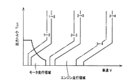
図6は、電子制御装置80による制御機能の要部を説明する機能ブロック線図である。図6において、有段変速制御手段82は、図7に示すような車速Vと自動変速部20の出力トルクTOUTとを変数として予め記憶されたアップシフト線(実線)およびダウンシフト線(一点鎖線)を有する関係(変速線図、変速マップ)から実際の車速Vおよび自動変速部20の要求出力トルクTOUTで示される車両状態に基づいて、自動変速部20の変速を実行すべきか否かを判断しすなわち自動変速部20の変速すべき変速段を判断し、その判断した変速段が得られるように自動変速部20の自動変速制御を実行する。
FIG. 6 is a functional block diagram illustrating a main part of the control function by the
このとき、有段変速制御手段82は、例えば図2に示す係合表に従って変速段が達成されるように、自動変速部20の変速に関与する油圧式摩擦係合装置を係合および/または解放させる指令(変速出力指令、油圧指令)を、すなわち自動変速部20の変速に関与する解放側係合装置を解放すると共に係合側係合装置を係合することによりクラッチツウクラッチ変速を実行させる指令を油圧制御回路70へ出力する。油圧制御回路70は、その指令に従って、例えば解放側係合装置を解放すると共に係合側係合装置を係合して自動変速部20の変速が実行されるように、油圧制御回路70内のリニアソレノイドバルブを作動させてその変速に関与する油圧式摩擦係合装置の油圧アクチュエータを作動させる。
At this time, the stepped shift control means 82 engages and / or engages the hydraulic friction engagement device involved in the shift of the
ハイブリッド制御手段84は、エンジン8を効率のよい作動域で作動させる一方で、エンジン8と第2電動機M2との駆動力の配分や第1電動機M1の発電による反力を最適になるように変化させて差動部11の電気的な無段変速機としての変速比γ0を制御する。例えば、そのときの走行車速Vにおいて、運転者の出力要求量としてのアクセル開度Accや車速Vから車両の目標(要求)出力を算出し、その車両の目標出力と充電要求値から必要なトータル目標出力を算出し、そのトータル目標出力が得られるように伝達損失、補機負荷、第2電動機M2のアシストトルク等を考慮して目標エンジン出力を算出し、その目標エンジン出力が得られるエンジン回転速度NEとエンジントルクTEとなるようにエンジン8を制御するとともに第1電動機M1の発電量を制御する。
The hybrid control means 84 operates the
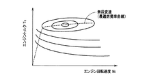
例えば、ハイブリッド制御手段84は、その制御を動力性能や燃費向上などのために自動変速部20の変速段を考慮して実行する。このようなハイブリッド制御では、エンジン8を効率のよい作動域で作動させるために定まるエンジン回転速度NEと車速Vおよび自動変速部20の変速段で定まる伝達部材18の回転速度とを整合させるために、差動部11が電気的な無段変速機として機能させられる。すなわち、ハイブリッド制御手段84は、エンジン回転速度NEとエンジン8の出力トルク(エンジントルク)TEとで構成される二次元座標内において無段変速走行の時に運転性と燃費性とを両立するように予め実験的に求められた図8の破線に示すようなエンジン8の動作曲線の一種である最適燃費率曲線(燃費マップ、関係)を予め記憶しており、その最適燃費率曲線にエンジン8の動作点(以下、「エンジン動作点」と表す)が沿わされつつエンジン8が作動させられるように、例えば目標出力(トータル目標出力、要求駆動力)を充足するために必要なエンジン出力を発生するためのエンジントルクTEとエンジン回転速度NEとなるように、動力伝達装置10のトータル変速比γTの目標値を定め、その目標値が得られるように自動変速部20の変速段を考慮して差動部11の変速比γ0を制御し、トータル変速比γTをその変速可能な変化範囲内で制御する。ここで、上記エンジン動作点とは、エンジン回転速度NE及びエンジントルクTEなどで例示されるエンジン8の動作状態を示す状態量を座標軸とした二次元座標においてエンジン8の動作状態を示す動作点である。
For example, the hybrid control means 84 executes the control in consideration of the gear position of the
このとき、ハイブリッド制御手段84は、第1電動機M1により発電された電気エネルギをインバータ54を通して蓄電装置56や第2電動機M2へ供給するので、エンジン8の動力の主要部は機械的に伝達部材18へ伝達されるが、エンジン8の動力の一部は第1電動機M1の発電のために消費されてそこで電気エネルギに変換され、インバータ54を通してその電気エネルギが第2電動機M2へ供給され、その第2電動機M2が駆動されて第2電動機M2から伝達部材18へ伝達される。この電気エネルギの発生から第2電動機M2で消費されるまでに関連する機器により、エンジン8の動力の一部を電気エネルギに変換し、その電気エネルギを機械的エネルギに変換するまでの電気パスが構成される。また必要に応じてハイブリッド制御手段84は、エンジン8の出力軸に連結された第3電動機M3を発電機として機能させてエンジン8の動力の一部を電気エネルギに変換し、その電気エネルギはインバータ54に供給される。
At this time, the hybrid control means 84 supplies the electric energy generated by the first electric motor M1 to the
また、ハイブリッド制御手段84は、車両の停止中又は走行中に拘わらず、差動部11の電気的CVT機能によって第1電動機回転速度NM1および/または第2電動機回転速度NM2を制御してエンジン回転速度NEを略一定に維持したり任意の回転速度に回転制御する。言い換えれば、ハイブリッド制御手段84は、エンジン回転速度NEを略一定に維持したり任意の回転速度に制御しつつ第1電動機回転速度NM1および/または第2電動機回転速度NM2を任意の回転速度に回転制御することができる。
Further, the hybrid control means 84 controls the first motor rotation speed N M1 and / or the second motor rotation speed N M2 by the electric CVT function of the
例えば、図3の共線図からもわかるようにハイブリッド制御手段84は車両走行中にエンジン回転速度NEを引き上げる場合には、車速V(駆動輪34)に拘束される第2電動機回転速度NM2を略一定に維持しつつ第1電動機回転速度NM1の引き上げを実行する。このときハイブリッド制御手段84は、第1電動機回転速度NM1の引き上げに替えて又はこれと並行して、第3電動機回転速度NM3の引き上げを実行してエンジン回転速度NEを引き上げてもよい。また、ハイブリッド制御手段84は自動変速部20の変速中にエンジン回転速度NEを略一定に維持する場合には、エンジン回転速度NEを略一定に維持しつつ自動変速部20の変速に伴う第2電動機回転速度NM2の変化とは反対方向に第1電動機回転速度NM1を変化させる。
For example, the hybrid control means 84 as can be seen from the diagram of FIG. 3 when raising the engine rotation speed N E during running of the vehicle, the vehicle speed V the second electric motor rotation speed N which is bound to the (drive wheels 34) The first motor rotation speed N M1 is increased while maintaining M2 substantially constant. In this case the hybrid control means 84, instead of the pulling of the first electric motor speed N M1 or in parallel with this, by performing the raising of the third electric motor rotation speed N M3 may pull the engine rotational speed N E . The hybrid control means 84 when maintaining the engine speed N E at the nearly fixed level during the shifting of the automatic shifting
また、ハイブリッド制御手段84は、スロットル制御のためにスロットルアクチュエータ64により電子スロットル弁62を開閉制御させる他、燃料噴射制御のために燃料噴射装置66による燃料噴射量や噴射時期を制御させ、点火時期制御のためにイグナイタ等の点火装置68による点火時期を制御させる指令を単独で或いは組み合わせてエンジン出力制御装置58に出力して、必要なエンジン出力を発生するようにエンジン8の出力制御を実行するエンジン出力制御手段を機能的に備えている。
Further, the hybrid control means 84 controls the opening and closing of the
例えば、ハイブリッド制御手段84は、基本的には図示しない予め記憶された関係からアクセル開度Accに基づいてスロットルアクチュエータ64を駆動し、アクセル開度Accが増加するほどスロットル弁開度θTHを増加させるようにスロットル制御を実行する。また、このエンジン出力制御装置58は、ハイブリッド制御手段84による指令に従って、スロットル制御のためにスロットルアクチュエータ64により電子スロットル弁62を開閉制御する他、燃料噴射制御のために燃料噴射装置66による燃料噴射を制御し、点火時期制御のためにイグナイタ等の点火装置68による点火時期を制御するなどしてエンジントルク制御を実行する。
For example, the
また、ハイブリッド制御手段84は、エンジン8の停止又はアイドル状態に拘わらず、差動部11の電気的CVT機能(差動作用)によって、第2電動機M2を走行用の駆動力源とするモータ走行をさせることができる。例えば、ハイブリッド制御手段84は、一般的にエンジン効率が高トルク域に比較して悪いとされる比較的低出力トルクTOUT域すなわち低エンジントルクTE域、或いは車速Vの比較的低車速域すなわち低負荷域において、モータ走行を実行する。また、ハイブリッド制御手段84は、このモータ走行時には、停止しているエンジン8の引き摺りを抑制して燃費を向上させるために、第1電動機回転速度NM1を負の回転速度で制御して例えば第1電動機M1を無負荷状態とすることにより空転させて、差動部11の電気的CVT機能(差動作用)により必要に応じてエンジン回転速度NEを零乃至略零に維持する。
Further, the hybrid control means 84 uses the second electric motor M2 as a driving force source for traveling by the electric CVT function (differential action) of the
また、ハイブリッド制御手段84は、エンジン8を走行用の駆動力源とするエンジン走行を行うエンジン走行領域であっても、上述した電気パスによる第1電動機M1からの電気エネルギおよび/または蓄電装置56からの電気エネルギを第2電動機M2へ供給し、その第2電動機M2を駆動して駆動輪34にトルクを付与することにより、エンジン8の動力を補助するための所謂トルクアシストが可能である。よって、本実施例のエンジン走行にはエンジン8を走行用の駆動力源とする場合と、エンジン8及び第2電動機M2の両方を走行用の駆動力源とする場合とがある。そして、本実施例のモータ走行とはエンジン8を停止して第2電動機M2を走行用の駆動力源とする走行である。
In addition, the hybrid control means 84 is the electric energy from the first electric motor M1 and / or the
また、ハイブリッド制御手段84は、第1電動機M1を無負荷状態として自由回転すなわち空転させることにより、差動部11がトルクの伝達を不能な状態すなわち差動部11内の動力伝達経路が遮断された状態と同等の状態であって、且つ差動部11からの出力が発生されない状態とすることが可能である。すなわち、ハイブリッド制御手段84は、第1電動機M1を無負荷状態とすることにより差動部11をその動力伝達経路が電気的に遮断される中立状態(ニュートラル状態)とすることが可能である。
Further, the hybrid control means 84 makes the first electric motor M1 in a no-load state and freely rotates, that is, idles, so that the
また、ハイブリッド制御手段84は、アクセルオフの惰性走行時(コースト走行時)やフットブレーキによる制動時などには、燃費を向上させるために車両の運動エネルギすなわち駆動輪34からエンジン8側へ伝達される逆駆動力により第2電動機M2を回転駆動させて発電機として作動させ、その電気エネルギすなわち第2電動機発電電流をインバータ54を介して蓄電装置56へ充電する回生制御手段としての機能を有する。この回生制御は、蓄電装置56の充電残量SOCやブレーキペダル操作量に応じた制動力を得るための油圧ブレーキによる制動力の制動力配分等に基づいて決定された回生量となるように制御される。
Further, the hybrid control means 84 is transmitted from the kinetic energy of the vehicle, that is, from the
ここで、エンジン走行中にエンジン8がフェイル状態となった場合などを想定すると、場合によってはエンジン8が停止することも考えられ、そのような場合にはそのエンジン回転速度NEの低下と差動部11の差動作用とによって図9のように第1電動機M1が負回転方向に高回転化させられることが考えれる。図9は、自動変速部20の第1ブレーキB1と第1クラッチC1とが係合された自動変速部20が第3速ギヤ段である場合を例とした上記第1電動機M1の高回転化を説明するための共線図である。図9によって上記第1電動機M1の高回転化を説明すれば、エンジン回転速度NEが矢印AR01のように低下すると第2電動機回転速度NM2は駆動輪34(車速V)に拘束されているためその低下に即応しては変化せず、エンジン回転速度NEの低下によって過渡的に矢印AR02のように第1電動機M1が負回転方向に高回転化させられることがある。
Here, when the
そこで、図9に示すように過渡的に第1電動機M1が高回転化させられることが抑制される制御が実行される。以下に、その制御機能の要部について説明する。 Therefore, as shown in FIG. 9, control is executed to suppress the first motor M <b> 1 from being transiently rotated at a high speed. The main part of the control function will be described below.
図6に戻り、走行状態判定手段90は、車両の走行状態がエンジン走行中であるか否かを判定する。 Returning to FIG. 6, the traveling state determination means 90 determines whether or not the traveling state of the vehicle is the engine traveling.
エンジン回転速度判定手段92は、走行状態判定手段90によって車両の走行状態がエンジン走行中であると判定された場合に、エンジン8が停止又は停止方向にその回転速度NEが低下したか否かを判定する。具体的には、エンジン回転速度判定手段92は、エンジン回転速度NEの単位時間当たりの低下量AEすなわちエンジン回転速度低下率AEが予め定められたエンジン回転速度低下率判定値XAEを超えてエンジン回転速度NEが低下したか否かを判定する。すなわち、エンジン回転速度判定手段92は、エンジン回転速度低下率AEがエンジン回転速度低下率判定値XAEを超えてエンジン回転速度NEが低下した場合に、エンジン8が停止又は停止方向にその回転速度NEが低下したとの旨を肯定する。ここで、エンジン回転速度低下率判定値XAEは、本発明の動力源回転速度低下率判定値に対応する実験的に求められた判定値であって、後述の高回転化抑制制御が実行されなければ第1電動機の耐久性がその高回転化により低下するおそれがあると判断されるエンジン回転速度NEの低下が生じたことを判定するための判定値である。また、エンジン回転速度NEの低下が判定されるので、エンジン回転速度NEの低下する方向がエンジン回転速度低下率AEの正方向であり、エンジン回転速度低下率判定値XAEは正の値である。
The engine speed determination means 92 determines whether or not the engine speed of the
エンジン回転速度判定手段92は走行状態判定手段90によって車両の走行状態がエンジン走行中であると判定された場合に上記エンジン回転速度低下率AEについての判定を行うが、その判定を走行状態判定手段90の判定結果に関わらず行ってもよい。
The engine rotation
差動部出力回転速度判定手段94は、差動部11の出力回転速度である伝達部材18の回転速度N18が予め定められた制御実行判定値XNM2以上であるか否かを判定する。具体的には伝達部材18には第2電動機M2が連結されているので、差動部出力回転速度判定手段94は第2電動機回転速度NM2が制御実行判定値XNM2以上であるか否かを判定する。ここで、上記制御実行判定値XNM2は、第2電動機回転速度NM2が高いほどエンジン回転速度NEが低下した場合に第1電動機M1が負回転方向に高回転化し易くなることを考慮して実験的に求められた判定値であって、第1電動機M1の耐久性維持のために後述の高回転化抑制制御を実行することを決定するための差動部11の出力回転速度(第2電動機回転速度NM2)についての判定値である。すなわち、制御実行判定値XNM2は、第2電動機回転速度NM2が制御実行判定値XNM2未満であれば後述の高回転化抑制制御が実行されなくても第1電動機M1の高回転化による耐久性低下が生じることはないと判断できる判定値である。
Differential unit output rotation
高回転化抑制制御必要性判定手段96は、走行中にエンジン8が停止した場合などエンジン回転速度NEが低下したとした場合に、後述の高回転化抑制制御が実行されず第1電動機M1及び第2電動機M2からの出力だけでは、第1電動機M1が後述の回転速度許容値XNM1を超えて負回転方向へ高回転化することを防止できないおそれがあるか否かを判定する。具体的には、上記第1電動機M1の高回転化を防止できるだけの十分な第1電動機M1及び第2電動機M2の出力が得られれば第1電動機M1及び第2電動機M2だけで上記高回転化は防止できるので、高回転化抑制制御必要性判定手段96は、第1電動機M1及び第2電動機M2だけでは上記第1電動機M1の高回転化を防止できないおそれがあるか否かを判定するするための判定値として、第1電動機M1の出力制限についての差動用電動機出力判定値XPM1と第2電動機M2の出力制限についての走行用電動機出力判定値XPM2とを予め実験的に求め記憶している。そして、高回転化抑制制御必要性判定手段96は、第1電動機の出力PM1(例えば、単位は「W」。以下、「第1電動機出力PM1」と表す。)が予め定められた差動用電動機出力判定値XPM1以下に制限され、又は、第2電動機の出力PM2(例えば、単位は「W」。以下、「第2電動機出力PM2」と表す。)が予め定められた走行用電動機出力判定値XPM2以下に制限されるか否かを判定する。すなわち、高回転化抑制制御必要性判定手段96は、第1電動機出力PM1が差動用電動機出力判定値XPM1以下に制限される場合、又は、第2電動機出力PM2が走行用電動機出力判定値XPM2以下に制限される場合には、第1電動機M1及び第2電動機M2だけでは上記第1電動機M1の高回転化を防止できないおそれがあることを肯定する旨の判定を行う。なお、上記差動用電動機出力判定値XPM1が第1電動機M1の定格出力以上である場合または走行用電動機出力判定値XPM2が第2電動機M2の定格出力以上である場合には、高回転化抑制制御必要性判定手段96は常に上記肯定する旨の判定を行うことになる。また、上記差動用電動機出力判定値XPM1及び走行用電動機出力判定値XPM2は、エンジン回転速度NEや第2電動機回転速度NM2などに応じて変化する判定値であってもよい。例えば、第2電動機回転速度NM2が高いほど第1電動機M1は高回転化し易くなるので、第2電動機回転速度NM2が高いほど上記差動用電動機出力判定値XPM1及び走行用電動機出力判定値XPM2が大きくなるように変化してもよいということである。
The high-rotation suppression control
高回転化抑制手段100は、走行状態判定手段90により車両の走行状態がエンジン走行中であると判定され、エンジン回転速度判定手段92によりエンジン8が停止又は停止方向にその回転速度NEが低下したと判定され、差動部出力回転速度判定手段94により第2電動機回転速度NM2が制御実行判定値XNM2以上であると判定され、且つ、高回転化抑制制御必要性判定手段96により第1電動機出力PM1が差動用電動機出力判定値XPM1以下に制限され又は第2電動機出力PM2が走行用電動機出力判定値XPM2以下に制限される旨を肯定する判定がなされた場合において、第1電動機回転速度NM1の絶対値が予め設定された回転速度許容値XNM1を超えないように第3電動機(動力源連結電動機)M3を制御する高回転化抑制制御を実行する。上記高回転化抑制制御の実行において高回転化抑制手段100は、具体的には、エンジン回転速度NEの低下を遅らせるように、すなわち、エンジン回転速度NEを上昇させる方向に、第3電動機M3にその出力トルクTM3(以下、「第3電動機トルクTM3」と表す)を発生させ、更に、エンジン回転速度NEを検出しつつそのエンジン回転速度NEが予め定められた回転速度変化(目標エンジン回転速度変化)に沿って低下するように第3電動機M3を制御するフィードバック制御により上記高回転化抑制制御を実行する。例えば、上記目標エンジン回転速度変化は、よく知られたアイドル回転速度以下のエンジン回転速度領域における共振領域(NE=200rpm付近)を速やかに回避するためその共振領域では早くエンジン回転速度NEが低下するように定められており、また、エンジン停止による振動を緩和するためエンジン停止時の回転速度NE変化が緩やかになるように定められている。なお、高回転化抑制手段100は上記高回転化抑制制御を上記フィードバック制御により実行するが、そのようなフィードバック制御ではなく、例えば、上記高回転化抑制制御においてエンジン回転速度NEの低下を阻止する方向に、蓄電装置56の充放電可能な電力に基づいて許容される第3電動機M3の最大トルクを出力するようにしてもよい。また、上記回転速度許容値XNM1は、第1電動機M1及びそれと連動して回転する差動部サンギヤS0、差動部遊星歯車P0などの回転要素の耐久性を維持するための第1電動機回転速度NM1の実験的に求められた上限値である。
High speed rotation suppressing means 100, the running state of the vehicle by the travel
上述のように高回転化抑制手段100は第3電動機M3に正回転方向のトルクTM3を出力させて上記高回転化抑制制御を実行するが、その高回転化抑制制御の実行と併せて、第1電動機回転速度NM1の絶対値が小さくなる方向に第1電動機M1と第2電動機M2とに可能な範囲でトルクを発生させてもよい。例えば第1電動機M1と第2電動機M2とを発電機として機能させて可能な範囲でそれらに回生トルクを発生させてもよいということである。
High rotation-inhibiting
係合制御手段102は、第3電動機(動力源連結電動機)M3の出力PM3(例えば、単位は「W」。以下、「第3電動機出力PM3」と表す。)が予め設定されたエンジン連結電動機出力判定値XPM3以下に制限されるが否かを判断する。ここで、上記エンジン連結電動機出力判定値XPM3は、本発明の動力源連結電動機出力判定値に対応する実験的に求められた判定値であって、その判定値XPM3以下に出力制限された第3電動機M3による上記高回転化抑制制御の実行のみでは前記第1電動機M1の高回転化を防止できないことがあると判断される判定値であり、第3電動機M3の定格出力未満の値である。 The engagement control means 102 is an engine in which an output P M3 (for example, the unit is “W”, hereinafter referred to as “third motor output P M3 ”) of a third motor (power source coupled motor) M3 is set in advance. It is determined whether or not it is limited to the coupled motor output determination value XP M3 or less. Here, the engine coupled motor output judgment value XP M3 is an experimentally obtained judgment value corresponding to the power source coupled motor output judgment value of the present invention, and the output is limited to the judgment value XP M3 or less. This is a determination value that determines that the high rotation of the first electric motor M1 may not be prevented only by the execution of the high rotation suppression control by the third electric motor M3, and is a value less than the rated output of the third electric motor M3. is there.
そして、図2に示すように自動変速部20の非変速中においては第1クラッチC1,第2クラッチC2の一方又は両方が係合されているところ、係合制御手段102は、第3電動機出力PM3がエンジン連結電動機出力判定値XPM3以下に制限されると判断した場合において、上記高回転化抑制手段100による高回転化抑制制御の実行を補助するため高回転化抑制手段100が上記高回転化抑制制御を実行する場合にそれと並行して、係合されている第1クラッチC1と第2クラッチC2との少なくとも一方を解放状態又はスリップ状態にする。本発明の係合装置には第1クラッチC1および第2クラッチC2が対応する。ここで、係合制御手段102が解放状態又はスリップ状態にする係合装置は第1クラッチC1、第2クラッチC2以外の自動変速部20の係合されているクラッチC又はブレーキBであってもよい。例えば、自動変速部20の変速段が第3速(3rd)である場合に係合制御手段102は、図2の係合表から第1クラッチC1および第2クラッチC2のうち係合されている係合装置は第1クラッチC1であるので、上記高回転化抑制制御と並行してその第1クラッチC1を解放状態又はスリップ状態にするが、上記第3速(3rd)では第1ブレーキB1も係合されているので、第1クラッチC1に替えて又はそれと併せて第1ブレーキB1を解放状態又はスリップ状態にしてもよいということである。
As shown in FIG. 2, when one or both of the first clutch C1 and the second clutch C2 are engaged while the
上述のように係合制御手段102は上記高回転化抑制制御と並行して、第1クラッチC1及び/又は第2クラッチC2を解放状態又はスリップ状態にするが、この係合制御手段102に替えて、有段変速制御手段82が上記高回転化抑制制御と並行して自動変速部20のアップシフトを行う制御機能も考え得る。これについて以下に説明する。なお、その場合の機能ブロック線図を図10に示す。
As described above, the engagement control means 102 puts the first clutch C1 and / or the second clutch C2 in the released state or the slip state in parallel with the high rotation suppression control. Thus, a control function in which the stepped shift control means 82 upshifts the
本発明の変速制御手段に対応する有段変速制御手段82は、前述の機能に加え、係合制御手段102の場合と同様に、第3電動機出力PM3が前記エンジン連結電動機出力判定値XPM3以下に制限されるが否かを判断する。そして、有段変速制御手段82は、第3電動機出力PM3がエンジン連結電動機出力判定値XPM3以下に制限されると判断した場合において、高回転化抑制手段100が上記高回転化抑制制御を実行する場合にそれと並行して、自動変速部20のアップシフトを行う。本実施例において、このアップシフトは図7の変速線図に関係なく現在の変速段から1段のアップシフトを行うものであるが、1段のアップシフトに限定されるものではない。
The stepped speed change control means 82 corresponding to the speed change control means of the present invention, in addition to the above-described function, is similar to the case of the engagement control means 102 in that the third motor output P M3 is the engine coupled motor output judgment value XP M3. Judge whether or not it is limited to the following. When the stepped shift control means 82 determines that the third motor output P M3 is limited to the engine coupled motor output determination value XP M3 or less, the high rotation suppression means 100 performs the high rotation suppression control. In parallel with the execution, the
図11は、電子制御装置80の制御作動の要部すなわち過渡的に第1電動機M1が高回転化させられることを抑制するための制御作動を説明するフローチャートであり、例えば数msec乃至数十msec程度の極めて短いサイクルタイムで繰り返し実行される。
FIG. 11 is a flowchart for explaining a main part of the control operation of the
先ず、走行状態判定手段90に対応するステップ(以下、「ステップ」を省略する)SA1においては、車両の走行状態がエンジン走行中であるか否かが判定される。この判定が肯定的である場合、すなわち、車両の走行状態がエンジン走行中である場合には、SA2に移る。一方、この判定が否定的である場合にはSA8に移る。 First, in a step (hereinafter, “step” is omitted) SA1 corresponding to the traveling state determination means 90, it is determined whether or not the traveling state of the vehicle is the engine traveling. If this determination is affirmative, that is, if the vehicle is running in the engine, the process proceeds to SA2. On the other hand, if this determination is negative, the operation moves to SA8.
エンジン回転速度判定手段92に対応するSA2においては、エンジン8が停止又は停止方向にその回転速度が低下したか否か、具体的には、エンジン回転速度低下率AEがエンジン回転速度低下率判定値XAEを超えてエンジン回転速度NEが低下したか否かが判定される。この判定が肯定的である場合、すなわち、エンジン回転速度低下率AEがエンジン回転速度低下率判定値XAEを超えてエンジン回転速度NEが低下した場合には、SA3に移る。一方、この判定が否定的である場合にはSA8に移る。
In SA2 corresponding to the engine rotation speed determination means 92, whether or not the
差動部出力回転速度判定手段94に対応するSA3においては、第2電動機回転速度NM2が前記制御実行判定値XNM2(所定値1)以上であるか否かが判定される。この判定が肯定的である場合、すなわち、第2電動機回転速度NM2が上記制御実行判定値XNM2以上である場合には、SA4に移る。一方、この判定が否定的である場合にはSA8に移る。 In SA3 corresponding to the differential unit output rotation speed determination means 94, it is determined whether or not the second motor rotation speed N M2 is equal to or higher than the control execution determination value XN M2 (predetermined value 1). If this determination is affirmative, that is, if the second motor rotation speed N M2 is equal to or higher than the control execution determination value XN M2 , the process proceeds to SA4. On the other hand, if this determination is negative, the operation moves to SA8.
高回転化抑制制御必要性判定手段96に対応するSA4においては、前記高回転化抑制制御が実行されずに第1電動機M1及び第2電動機M2からの出力だけでは、第1電動機M1が前記回転速度許容値XNM1を超えて負回転方向へ高回転化することを防止できない可能性があるか否かが判定される。具体的には、第1電動機出力PM1が前記差動用電動機出力判定値XPM1以下に制限され、又は、第2電動機出力PM2が前記走行用電動機出力判定値XPM2以下に制限されるか否かが判定される。例えば、第1電動機M1および第2電動機M2の熱的作動条件や蓄電装置56の充放電制限やインバータ54の能力などに基づいて第1電動機出力PM1および第2電動機出力PM2が制限される。この判定が肯定的である場合、すなわち、第1電動機出力PM1が差動用電動機出力判定値XPM1以下に制限される場合、又は、第2電動機出力PM2が走行用電動機出力判定値XPM2以下に制限される場合には、SA5に移る。一方、この判定が否定的である場合にはSA8に移る。
In SA4 corresponding to the high rotation suppression control necessity determination means 96, the high rotation suppression control is not executed, and only the outputs from the first motor M1 and the second motor M2 cause the first motor M1 to rotate. It is determined whether or not there is a possibility that it is not possible to prevent high speed rotation in the negative rotation direction exceeding the speed allowable value XN M1 . Specifically, the first motor output P M1 is limited to the differential motor output determination value XP M1 or less, or the second motor output P M2 is limited to the travel motor output determination value XP M2 or less. It is determined whether or not. For example, the first motor output P M1 and the second motor output P M2 are limited based on the thermal operation conditions of the first motor M1 and the second motor M2, the charge / discharge limitation of the
高回転化抑制手段100に対応するSA5においては、第1電動機回転速度NM1の絶対値が前記回転速度許容値XNM1を超えないように第3電動機M3を制御する前記高回転化抑制制御が実行される。例えば、その高回転化抑制制御は、エンジン回転速度NEを検出しつつそのエンジン回転速度NEが予め定められた目標エンジン回転速度変化に沿って低下するように第3電動機M3を制御するフィードバック制御により実行される。或いは、そのようなフィードバック制御ではなく、上記高回転化抑制制御においてエンジン回転速度NEの低下を阻止する方向すなわち正回転方向(NE上昇方向)に、蓄電装置56の充放電可能な電力に基づいて許容される第3電動機M3の最大トルク、言い換えれば、蓄電装置56の充放電収支の許容範囲内で出力可能な第3電動機M3の最大トルクが出力されるようにしてもよい。
In SA5 corresponding to the high rotation suppression means 100, the high rotation suppression control for controlling the third electric motor M3 so that the absolute value of the first electric motor rotation speed N M1 does not exceed the rotation speed allowable value XN M1 is performed. Executed. For example, the high rotation suppression control, feedback controls the third electric motor M3 to decrease along with the detected while the target engine rotational speed change that engine rotational speed N E is predetermined engine rotational speed N E It is executed by control. Alternatively, instead of such a feedback control, in the high direction prevents reduction of the engine speed N E in the rotation-suppressing control or the forward rotational direction (N E ascending direction), the
更にSA5においては、上記高回転化抑制制御の実行と併せて、第1電動機回転速度NM1の絶対値が小さくなる方向に第1電動機M1と第2電動機M2とから可能な範囲でトルクが出力される。これにより、上記高回転化抑制制御が、第1電動機M1と第2電動機M2とによりトルクアシストされる。 Further, in SA5, in conjunction with the execution of the high rotation suppression control, torque is output within a possible range from the first electric motor M1 and the second electric motor M2 in a direction in which the absolute value of the first electric motor rotation speed NM1 decreases. Is done. Thereby, the high rotation suppression control is torque-assisted by the first electric motor M1 and the second electric motor M2.
係合制御手段102に対応するSA6においては、第3電動機出力PM3が前記エンジン連結電動機出力判定値XPM3以下に制限されるが否かが判断される。例えば、第3電動機M3の熱的作動条件や蓄電装置56の充放電制限などから第3電動機出力PM3が制限されることがある。この判断が肯定的である場合、すなわち、第3電動機出力PM3が上記エンジン連結電動機出力判定値XPM3以下に制限される場合には、SA7に移る。一方、この判断が否定的である場合には本フローチャートは終了する。
In SA6 corresponding to the engagement control means 102, it is determined whether or not the third motor output P M3 is limited to the engine coupled motor output determination value XP M3 or less. For example, the third motor output P M3 may be limited due to the thermal operation condition of the third motor M3, the charge / discharge limitation of the
係合制御手段102に対応するSA7においては、前記高回転化抑制制御の実行と並行して、自動変速部20が有する係合されている係合装置すなわち係合されている第1クラッチC1と第2クラッチC2との少なくとも一方が解放状態又はスリップ状態にされる。
In SA7 corresponding to the engagement control means 102, in parallel with the execution of the high rotation suppression control, the engaged engagement device of the
ここで上記図11のSA7は図12のSA7’に置換されてもよい。そのように置換された場合、図12のSA7’においては、前記高回転化抑制制御の実行と並行して、自動変速部20のアップシフトが行われる。なお、SA7がSA7’に置換された場合は、SA6とSA7’とが有段変速制御手段82に対応する。
Here, SA7 in FIG. 11 may be replaced with SA7 'in FIG. If so replaced, in SA7 'of FIG. 12, the
SA8においては、モータ走行中の制御などのその他の制御が実施される。 In SA8, other control such as control during motor running is performed.
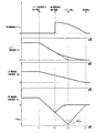
図13は、図11のフローチャートに示す制御作動を説明するためのタイムチャートであって、エンジン走行中にエンジン8が停止した場合の例である。この図13では、上から順に第3電動機トルクTM3、エンジン回転速度NE、第2電動機回転速度NM2、第1電動機回転速度NM1のタイムチャートである。なお、本タイムチャートにおいて実線は前記高回転化抑制制御が実行された場合のタイムチャートを示しており、破線はその高回転化抑制制御が実行されなかったとした場合のタイムチャートを示している。
FIG. 13 is a time chart for explaining the control operation shown in the flowchart of FIG. 11, and is an example when the
図13のtA1時点は、エンジン8がフェイル状態になるなどして、エンジン回転速度低下率判定値XAEを超えるエンジン回転速度低下率AEでエンジン回転速度NEが低下し始めたことを示している。そして、そのエンジン回転速度NEの低下に伴いtA1時点から、第1電動機回転速度NM1及び第2電動機回転速度NM2も低下し始めている。但し、エンジン8は電動機M1,M2に対して回転抵抗が大きく第2電動機M2は駆動輪34に拘束されているので、何もしなければ第2電動機回転速度NM2よりもエンジン回転速度NEの方が速く零に向けて低下する。そのためtA1時点からtA2時点の間で動力分配機構16の差動作用により第1電動機回転速度NM1の絶対値が負回転方向へ大きくなっている。
T A1 point in FIG. 13, and the like the
tA2時点は、図11のSA5にて前記高回転化抑制制御が開始されたことを示している。その高回転化抑制制御の実行によりtA2時点から第3電動機トルクTM3がエンジン回転速度NEの低下を遅らせる方向つまり正回転方向(NE上昇方向)に発生している。そのため、tA2時点から上記高回転化抑制制御が実行されなかったとすればエンジン回転速度NEは図13の破線で示すように低下するところ、その破線に対して、上記高回転化抑制制御が実行されたことにより図13の実線で示されるように、エンジン回転速度NEの低下が遅らされている。その結果、tA1時点から第1電動機回転速度NM1は負回転方向へその絶対値が増大していたところ、tA2時点で第1電動機回転速度NM1の変化方向が動力分配機構16の差動作用により反転し、tA2時点から第1電動機回転速度NM1が零に向けて収束を開始している。すなわち、上記高回転化抑制制御が実行されたことにより、図13の実線で示されるように、第1電動機回転速度NM1はtA2時点で負回転方向の最大値となり、第1電動機回転速度NM1の絶対値が回転速度許容値XNM1を超えなかったことが示されている。
The time t A2 indicates that the high rotation suppression control is started in SA5 of FIG. As the time t A2 by the execution of the high speed rotation suppression control third motor torque T M3 is generated in a direction that is normal rotation direction delaying the reduction in the engine rotational speed N E (N E ascending direction). Therefore, when the high-speed rotation suppression control from time t A2 is if was not executed engine rotational speed N E is to be reduced as indicated by the broken lines in FIG. 13, for the broken line, the high-speed rotation suppression control as indicated by the solid line in FIG. 13 by being executed, reduction of the engine rotational speed N E is delayed. As a result, the absolute value of the first motor rotation speed N M1 has increased in the negative rotation direction from the time point t A1 , and the change direction of the first motor rotation speed N M1 is the difference of the
tA3時点は、図13の破線で示されるように、上記高回転化抑制制御が実行されなかったとした場合のエンジン8が回転停止した時点を示している。上記高回転化抑制制御が実行されなかったとすれば、図13の破線で示されるように、このtA3時点で第1電動機回転速度NM1は負回転方向の最大値となり、tA3時点付近のANM1部分で第1電動機回転速度NM1の絶対値が回転速度許容値XNM1を超えてしまうことが示されている。
As shown by the broken line in FIG. 13, the time point t A3 indicates a time point when the
tA4時点は、走行していた車両が停止し、第2電動機回転速度NM2およびエンジン回転速度NEが零に至ったことを示している。それらの回転速度NM2,NEが零に至ったので動力分配機構16の差動作用により第1電動機回転速度NM1もtA4時点で零に至っている。そして、tA4時点で上記高回転化抑制制御が終了している。
t A4 point, the vehicle was traveling is stopped, the second electric motor rotation speed N M2 and engine speed N E indicates that it has reached zero. Their rotation speed N M2, N E is the first electric motor speed N M1 by the differential action of the
tA2時点からtA4時点までの間で第3電動機トルクTM3が正回転方向へ出力される上記高回転化抑制制御が実行されているが、本タイムチャートの高回転化抑制制御は、エンジン回転速度NEについての前記フィードバック制御により実行され、エンジン停止時を示すtA4時点の前において上記フィードバック制御によりエンジン回転速度NEが緩やかに変化してtA4時点で零に至っていることが示されている。 The high rotation suppression control in which the third electric motor torque T M3 is output in the forward rotation direction is performed between the time t A2 and the time t A4. It is performed by the feedback control of the rotational speed N E, that the above feedback control the engine speed N E and reaches zero at t A4 point changes gradually in front of t A4 point indicating the time of engine stop shown Has been.
本実施例の電子制御装置80には次のような効果(A1)乃至(A11)がある。(A1)高回転化抑制手段100は、走行状態判定手段90により車両の走行状態がエンジン走行中であると判定され、エンジン回転速度判定手段92によりエンジン8が停止又は停止方向にその回転速度NEが低下したと判定された場合に、他の条件を具備のもと、第1電動機回転速度NM1の絶対値が予め設定された回転速度許容値XNM1を超えないように第3電動機(動力源連結電動機)M3を制御する高回転化抑制制御を実行する。従って、エンジン回転速度NE低下に起因した第1電動機M1及びそれと連動して回転する差動部サンギヤS0、差動部遊星歯車P0などの回転要素の高回転化が防止され、その耐久性低下が抑制される。
The
(A2)図2に示すように自動変速部20の非変速中においては第1クラッチC1,第2クラッチC2の一方又は両方が係合されているところ、係合制御手段102は、高回転化抑制手段100が上記高回転化抑制制御を実行する場合にそれと並行して、係合されている第1クラッチC1と第2クラッチC2との少なくとも一方を解放状態又はスリップ状態にする。従って、動力分配機構16の差動状態が車速Vに完全には拘束されない状態となって動力分配機構16の差動作用が第1電動機M1の高回転化を助長することが抑えられ、上記高回転化抑制制御の実行により第1電動機M1及びそれと連動して回転する差動部サンギヤS0、差動部遊星歯車P0などの回転要素の高回転化を抑制し易くなる。
(A2) As shown in FIG. 2, when one or both of the first clutch C1 and the second clutch C2 are engaged during non-shifting of the
(A3)係合制御手段102は、上記係合されている第1クラッチC1と第2クラッチC2との少なくとも一方を解放状態又はスリップ状態にすることを、第3電動機出力PM3がエンジン連結電動機出力判定値XPM3以下に制限されると判断した場合に行うので、必要性の高い場合に上記第1クラッチC1及び/又は第2クラッチC2が解放状態またはスリップ状態とされ、第1電動機M1の高回転化を防止するときの制御負荷の軽減を図り得る。 (A3) The engagement control means 102 indicates that at least one of the engaged first clutch C1 and second clutch C2 is in a released state or a slipped state, the third motor output P M3 is an engine coupled motor. Since it is performed when it is determined that the output determination value XP M3 is limited to be equal to or less than the output determination value XP M3, the first clutch C1 and / or the second clutch C2 are released or slipped when the necessity is high, and the first electric motor M1 It is possible to reduce the control load when preventing high rotation.
(A4)本実施例では、上記係合制御手段102が第1クラッチC1及び/又は第2クラッチC2を解放状態又はスリップ状態にすることに替えて、有段変速制御手段82は、高回転化抑制手段100が上記高回転化抑制制御を実行する場合にそれと並行して、自動変速部20のアップシフトを行ってもよく、そのようにした場合には、そのアップシフトにより動力分配機構16の出力回転速度である第2電動機回転速度NM2が低下させられて動力分配機構16の差動作用に起因した第1電動機M1の高回転化が抑えられ、上記高回転化抑制制御の実行により第1電動機M1及びそれと連動して回転する差動部サンギヤS0、差動部遊星歯車P0などの回転要素の高回転化を抑制し易くなる。
(A4) In this embodiment, instead of the engagement control means 102 putting the first clutch C1 and / or the second clutch C2 into the disengaged state or the slip state, the stepped speed change control means 82 increases the rotation speed. When the
(A5)有段変速制御手段82は上記アップシフトを、第3電動機出力PM3がエンジン連結電動機出力判定値XPM3以下に制限されると判断した場合に、上記高回転化抑制制御と並行して行うので、必要性の高い場合に上記アップシフトが行われ、第1電動機M1の高回転化を防止するときの制御負荷の軽減を図り得る。 (A5) When the stepped shift control means 82 determines that the upshift is limited to the third motor output P M3 being equal to or less than the engine coupled motor output determination value XP M3 , the stepped shift control means 82 is in parallel with the high rotation suppression control. Therefore, when the necessity is high, the upshift is performed, and the control load when preventing the first motor M1 from rotating at a high speed can be reduced.
(A6)高回転化抑制手段100は、差動部出力回転速度判定手段94により第2電動機回転速度NM2が制御実行判定値XNM2以上であると判定された場合に、他の条件を具備のもと、前記高回転化抑制制御を実行する。従って、第1電動機M1の高回転化によりその耐久性が低下する可能性がある場合乃至はその可能性が高い場合に特に上記高回転化抑制制御が実行されることとなり、制御負荷の軽減を図り、効果的に第1電動機M1及びそれと連動して回転する差動部サンギヤS0、差動部遊星歯車P0などの回転要素の高回転化を防止できる。 (A6) The high rotation suppression means 100 has other conditions when it is determined by the differential portion output rotation speed determination means 94 that the second motor rotation speed N M2 is equal to or higher than the control execution determination value XN M2. The high rotation suppression control is executed. Therefore, when the durability of the first electric motor M1 is likely to decrease or when the possibility is high, the high rotation suppression control is executed, and the control load is reduced. As a result, it is possible to effectively prevent the rotation of the first electric motor M1 and the rotating elements such as the differential sun gear S0 and the differential planetary gear P0 that rotate in conjunction with the first motor M1.
(A7)エンジン回転速度NEの変化が緩やかであれば第1電動機M1はその出力トルクTM1により高回転化を防止し得るところ、エンジン回転速度判定手段92は、エンジン回転速度低下率AEが前記エンジン回転速度低下率判定値XAEを超えてエンジン回転速度NEが低下した場合に、エンジン8が停止又は停止方向にその回転速度NEが低下したとの旨を肯定する。そして、高回転化抑制手段100は、エンジン回転速度判定手段92によりエンジン8が停止又は停止方向にその回転速度が低下したと判定された場合に、他の条件を具備のもと、前記高回転化抑制制御を実行する。従って、第1電動機M1の高回転化によりその耐久性が低下する可能性がある場合乃至はその可能性が高い場合に特に上記高回転化抑制制御が実行されることとなり、制御負荷の軽減を図り、効果的に第1電動機M1及びそれと連動して回転する差動部サンギヤS0、差動部遊星歯車P0などの回転要素の高回転化を防止できる。
(A7) where the first electric motor M1 when the change in the engine rotational speed N E is a gradual capable of preventing a high-speed rotation by the output torque T M1, the engine rotation
(A8)高回転化抑制手段100は、上記高回転化抑制制御においてエンジン回転速度NEの低下を阻止する方向(正回転方向)に、蓄電装置56の充放電可能な電力に基づいて許容される第3電動機M3の最大トルク、言い換えれば、蓄電装置56の充放電収支の許容範囲内で出力可能な第3電動機M3の最大トルクを出力するようにしてもよく、そのようにすれば、第1電動機M1及びそれと連動して回転する差動部サンギヤS0、差動部遊星歯車P0などの回転要素の高回転化が最大限防止される。
(A8) high rotation-inhibiting
(A9)高回転化抑制手段100は、エンジン回転速度NEを検出しつつそのエンジン回転速度NEが予め定められた目標エンジン回転速度変化に沿って低下するように第3電動機M3を制御するフィードバック制御により上記高回転化抑制制御を実行するので、エンジン回転速度NEの低下、具体的にはエンジン8の停止による快適性低下を抑えることが可能である。
(A9) high rotation-inhibiting
(A10)高回転化抑制手段100は、高回転化抑制制御必要性判定手段96により第1電動機出力PM1が差動用電動機出力判定値XPM1以下に制限され又は第2電動機出力PM2が走行用電動機出力判定値XPM2以下に制限される旨を肯定する判定がなされた場合に、他の条件を具備のもと、前記高回転化抑制制御を実行する。従って、第1電動機出力PM1および第2電動機出力PM2だけでは第1電動機M1の高回転化を防止できない可能性がある場合に上記高回転化抑制制御が実行され、第1電動機M1の高回転化を防止するときの制御負荷の軽減を図り得る。 (A10) In the high rotation suppression means 100, the first motor output P M1 is limited to the differential motor output determination value XP M1 or less by the high rotation suppression control necessity determination means 96 or the second motor output P M2 is When it is determined that the motor output determination value XP M2 for traveling is limited to be equal to or lower than the traveling motor output determination value XP M2 , the high rotation suppression control is executed under other conditions. Therefore, when there is a possibility that high rotation of the first motor M1 cannot be prevented by only the first motor output P M1 and the second motor output P M2 , the high rotation suppression control is executed, and the high rotation of the first motor M1 is performed. It is possible to reduce the control load when preventing rotation.
(A11)高回転化抑制手段100は、上記高回転化抑制制御の実行と併せて、第1電動機回転速度NM1の絶対値が小さくなる方向に第1電動機M1と第2電動機M2とに可能な範囲でトルクを発生させてもよく、そのようにした場合には、第3電動機M3からの出力のみにより第1電動機M1及びそれと連動して回転する回転要素の高回転化を防止する場合と比較して、より充分に第1電動機M1及びそれと連動して回転する回転要素の高回転化を防止できる。 (A11) The high rotation suppression means 100 can be applied to the first electric motor M1 and the second electric motor M2 in the direction in which the absolute value of the first electric motor rotation speed N M1 decreases in conjunction with the execution of the high rotation suppression control. The torque may be generated within a range, and in such a case, the first motor M1 and the rotating element that rotates in conjunction with the first motor M1 can be prevented from increasing at high speed only by the output from the third motor M3. In comparison, it is possible to prevent the first motor M1 and the rotating element that rotates in conjunction with the first motor M1 from rotating more sufficiently.
以上、本発明の実施例を図面に基づいて詳細に説明したが、これはあくまでも一実施形態であり、本発明は当業者の知識に基づいて種々の変更、改良を加えた態様で実施することができる。 As mentioned above, although the Example of this invention was described in detail based on drawing, this is an embodiment to the last, and this invention is implemented in the aspect which added various change and improvement based on the knowledge of those skilled in the art. Can do.
例えば、前述の実施例において、図11のフローチャートではSA3およびSA4で肯定的な判定がなされた場合にSA5にて前記高回転化抑制制御が実行されるが、そのSA3およびSA4のいずれか一方または両方のステップが無いフローチャートであってもよい。 For example, in the above-described embodiment, in the flowchart of FIG. 11, when a positive determination is made in SA3 and SA4, the high rotation suppression control is executed in SA5, either one of SA3 and SA4 or A flowchart without both steps may be used.
また、前述の実施例においては、図11のフローチャートのSA5で上記高回転化抑制制御の実行と併せて、第1電動機回転速度NM1の絶対値が小さくなる方向に第1電動機M1と第2電動機M2とから可能な範囲でトルクが出力されるが、そのように第1電動機M1と第2電動機M2とからトルクが出力されなくてもよい。 In the above-described embodiment, the first electric motor M1 and the second electric motor M2 are arranged in the direction in which the absolute value of the first electric motor rotation speed NM1 decreases in conjunction with the execution of the high rotation suppression control in SA5 of the flowchart of FIG. Torque is output as much as possible from the electric motor M2, but the torque may not be output from the first electric motor M1 and the second electric motor M2 as such.
また、前述の実施例において、図11のフローチャートではSA6で肯定的な判断がなされた場合にSA7が実行されるが、そのSA6が無いフローチャートであってもよい。 In the above-described embodiment, SA7 is executed when a positive determination is made in SA6 in the flowchart of FIG. 11, but a flowchart without SA6 may be used.
また、前述の実施例の図11のフローチャートはSA6およびSA7を含んでいるが、そのSA6およびSA7が無いフローチャートであってもよい。 Further, although the flowchart of FIG. 11 of the above-described embodiment includes SA6 and SA7, it may be a flowchart without SA6 and SA7.
また、前述の実施例において、動力伝達装置10は第2電動機M2を備えているが、この第2電動機M2が無い構成であってもよい。
Moreover, in the above-mentioned Example, although the
動力伝達装置10内の作動流体である自動変速部20の作動油は自動変速部20のクラッチ(ブレーキ)B1,B2,B3,C1,C2の油圧用として用いられるものである。そのため、自動変速部20の作動油(作動流体)の温度TOIL(作動油温TOIL)が低いほど油圧で作動する上記クラッチ(ブレーキ)B1,B2,B3,C1,C2の制御信号に対する応答性が低下する傾向にある。また、そのクラッチ(ブレーキ)B1,B2,B3,C1,C2は湿式多板型であるので、そのクラッチ(ブレーキ)B1,B2,B3,C1,C2内の複数枚の摩擦板の互いの間に介在する作動油が極めて低温になるとその粘度が高まり適切なスリップ状態に制御し難くなる。そこで、図11のフローチャートのSA3で判定に用いられる前記制御実行判定値XNM2は一定値ではなく、上記作動油温TOILに基づいて変更されてもよい。例えば、図11のフローチャートにおいてSA2とSA3との間に図14のようにSA3’が追加され、そのSA3’において作動油温TOILが低いほど制御実行判定値XNM2が小さくなるように設定変更されてもよい。そのようにすれば、上記制御信号に対するクラッチ(ブレーキ)B1,B2,B3,C1,C2の応答性の変化に応じて、要するにそれらの制御の困難性に応じてフローチャートのSA7(図11参照)もしくはSA7’(図12参照)の実行される条件が変更され、適切に上記クラッチ(ブレーキ)B1,B2,B3,C1,C2を含む自動変速部20が第1電動機M1の高回転化を防止するように作動する。なお、上記図14のSA3’は差動部出力回転速度判定手段94に対応する。
The hydraulic fluid of the
また、前述の実施例では、第2電動機M2は、伝達部材18に直接連結されているが、第2電動機M2の連結位置はそれに限定されず、エンジン8又は伝達部材18から駆動輪34までの間の動力伝達経路に直接的或いは変速機、遊星歯車装置、係合装置等を介して間接的に連結されていてもよい。
In the above-described embodiment, the second electric motor M2 is directly connected to the
また、前述の実施例では、第1電動機M1の運転状態が制御されることにより、差動部11はその変速比γ0が最小値γ0minから最大値γ0maxまで連続的に変化させられる電気的な無段変速機として機能するものであったが、たとえば差動部11の変速比γ0を連続的ではなく差動作用を利用して敢えて段階的に変化させるものであっても本発明は適用することができる。
Further, in the above-described embodiment, by controlling the operating state of the first electric motor M1, the
また、前述の実施例において、差動部11は、動力分配機構16に設けられて差動作用を制限することにより少なくとも前進2段の有段変速機としても作動させられる差動制限装置を備えたものであってもよい。
In the above-described embodiment, the
また、前述の実施例の動力分配機構16では、差動部キャリヤCA0がエンジン8及び第3電動機M3に連結され、差動部サンギヤS0が第1電動機M1に連結され、差動部リングギヤR0が伝達部材18に連結されていたが、それらの連結関係は、必ずしもそれに限定されるものではなく、エンジン8及び第3電動機M3、第1電動機M1、伝達部材18は、差動部遊星歯車装置24の3要素CA0、S0、R0のうちのいずれと連結されていても差し支えない。
In the
また、前述の実施例では、エンジン8は入力軸14と直結されていたが、たとえばギヤ、ベルト等を介して作動的に連結されておればよく、共通の軸心上に配置される必要もない。
In the above-described embodiment, the
また、前述の実施例では、第1電動機M1、第2電動機M2及び第3電動機M3は、入力軸14に同心に配置されて第1電動機M1は差動部サンギヤS0に連結され第2電動機M2は伝達部材18に連結され第3電動機M3は差動部キャリヤCA0に連結されていたが、必ずしもそのように配置される必要はなく、たとえばギヤ、ベルト、減速機等を介して作動的に第1電動機M1は差動部サンギヤS0に連結され、第2電動機M2は伝達部材18に連結され、第3電動機M3は差動部キャリヤCA0に連結されていてもよい。
In the above-described embodiment, the first electric motor M1, the second electric motor M2, and the third electric motor M3 are disposed concentrically with the
また、前述の実施例において、第1クラッチC1や第2クラッチC2などの油圧式摩擦係合装置は、パウダー(磁紛)クラッチ、電磁クラッチ、噛合型のドグクラッチなどの磁紛式、電磁式、機械式係合装置から構成されていてもよい。たとえば電磁クラッチであるような場合には、油圧制御回路70は油路を切り換える弁装置ではなく電磁クラッチへの電気的な指令信号回路を切り換えるスイッチング装置や電磁切換装置等により構成される。
In the above-described embodiment, the hydraulic friction engagement device such as the first clutch C1 and the second clutch C2 is a magnetic type such as a powder (magnetic powder) clutch, an electromagnetic clutch, an engagement type dog clutch, an electromagnetic type, You may be comprised from the mechanical engagement apparatus. For example, in the case of an electromagnetic clutch, the
また、前述の実施例では、自動変速部20は伝達部材18を介して差動部11と直列に連結されていたが、入力軸14と平行にカウンタ軸が設けられてそのカウンタ軸上に同心に自動変速部20が配列されていてもよい。この場合には、差動部11と自動変速部20とは、たとえば伝達部材18としてカウンタギヤ対、スプロケットおよびチェーンで構成される1組の伝達部材などを介して動力伝達可能に連結される。
In the above-described embodiment, the
また、前述の実施例の差動機構として動力分配機構16は、たとえばエンジンによって回転駆動されるピニオンと、そのピニオンに噛み合う一対のかさ歯車が第1電動機M1および伝達部材18(第2電動機M2)に作動的に連結された差動歯車装置であってもよい。
The
また、前述の実施例ではエンジン8と差動部11とが直接連結されているが、必ずしも直接連結される必要はなく、エンジン8と差動部11とがそれらの間にクラッチを介して連結されていてもよい。
In the above-described embodiment, the
また、前述の実施例では、差動部11と自動変速部20とが直列接続されたような構成となっているが、特にこのような構成に限定されず、動力伝達装置10全体として電気式差動を行う機能と、動力伝達装置10全体として電気式差動による変速とは異なる原理で変速を行う機能とを、備えた構成であれば本発明は適用可能であり、機械的に独立している必要はない。また、これらの配設位置や配設順序も特に限定されない。要するに、自動変速部20は、エンジン8から駆動輪34への動力伝達経路の一部を構成するように設けられておればよい。
In the above-described embodiment, the
また、前述の実施例の動力分配機構16は、1組の遊星歯車装置(差動部遊星歯車装置24)から構成されていたが2以上の遊星歯車装置から構成されて、非差動状態(定変速状態)では3段以上の変速機として機能するものであってもよい。また、差動部遊星歯車装置24はシングルピニオン型に限られたものではなくダブルピニオン型の遊星歯車装置であってもよい。また、このような2以上の遊星歯車装置から構成された場合においても、これらの遊星歯車装置の各回転要素にエンジン8、第1および第2電動機M1、M2、伝達部材18、構成によっては出力軸22が動力伝達可能に連結され、さらに遊星歯車装置の各回転要素に接続されたクラッチCおよびブレーキBの制御により有段変速と無段変速とが切り換えられるような構成であっも構わない。
In addition, the
また、前述の実施例の動力伝達装置10において第1電動機M1と第2回転要素RE2とは直結されており、第2電動機M2と第3回転要素RE3とは直結されており、第3電動機M3と第1回転要素RE1とは直結されているが、第1電動機M1が第2回転要素RE2にクラッチ等の係合要素を介して連結され、第2電動機M2が第3回転要素RE3にクラッチ等の係合要素を介して連結され、第3電動機M3が第1回転要素RE1にクラッチ等の係合要素を介して連結されていてもよい。
In the
また、前述の実施例において、第2電動機M2はエンジン8から駆動輪34までの動力伝達経路の一部を構成する伝達部材18に連結されているが、第2電動機M2がその動力伝達経路に連結されていることに加え、クラッチ等の係合要素を介して動力分配機構16にも連結可能とされており、第1電動機M1の代わりに第2電動機M2によって動力分配機構16の差動状態を制御可能とする動力伝達装置10の構成であってもよい。
In the above-described embodiment, the second electric motor M2 is connected to the
また、前述の実施例において自動変速部20は有段の自動変速機として機能する変速部であるが、無段のCVTであってもよいし、手動変速機として機能する変速部であってもよい。
In the above-described embodiment, the
また前述の実施例において、差動部11が、第1電動機M1、第2電動機M2及び第3電動機M3を備えているが、第1電動機M1、第2電動機M2及び第3電動機M3は差動部11とはそれぞれ別個に動力伝達装置10に備えられていてもよい。
In the above-described embodiment, the
その他、一々例示はしないが、本発明はその趣旨を逸脱しない範囲内において種々の変更が加えられて実施されるものである。 In addition, although not illustrated one by one, the present invention is implemented with various modifications within a range not departing from the gist thereof.
8:エンジン(動力源)
10:動力伝達装置(車両用動力伝達装置)
11:差動部(電気式差動部)
16:動力分配機構(差動機構)
20:自動変速部
34:駆動輪
56:蓄電装置
80:電子制御装置(制御装置)
82:有段変速制御手段(変速制御手段)
100:高回転化抑制手段
102:係合制御手段
M1:第1電動機(差動用電動機)
M2:第2電動機(走行用電動機)
M3:第3電動機(動力源連結電動機)
C1:第1クラッチ(係合装置)
C2:第2クラッチ(係合装置)
XNM1:回転速度許容値
XNM2:制御実行判定値
XPM1:差動用電動機出力判定値
XPM2:走行用電動機出力判定値
XPM3:エンジン連結電動機出力判定値(動力源連結電動機出力判定値)
XAE:エンジン回転速度低下率判定値(動力源回転速度低下率判定値)
TOIL:作動油温(作動流体の温度)
8: Engine (power source)
10: Power transmission device (vehicle power transmission device)
11: Differential part (electrical differential part)
16: Power distribution mechanism (differential mechanism)
20: Automatic transmission unit 34: Drive wheel 56: Power storage device 80: Electronic control device (control device)
82: Stepped shift control means (shift control means)
100: High rotation suppression means 102: Engagement control means M1: First electric motor (differential electric motor)
M2: Second electric motor (traveling motor)
M3: Third motor (power source coupled motor)
C1: First clutch (engagement device)
C2: Second clutch (engagement device)
XN M1 : Rotational speed allowable value XN M2 : Control execution determination value XP M1 : Differential motor output determination value XP M2 : Driving motor output determination value XP M3 : Engine coupled motor output determination value (power source coupled motor output determination value) )
XAE : Engine rotation speed decrease rate determination value (power source rotation speed decrease rate determination value)
T OIL : Hydraulic oil temperature (temperature of the working fluid)
Claims (12)
車両走行中に前記動力源が停止又は停止方向にその回転速度が低下した場合には、前記差動用電動機の回転速度の絶対値が予め設定された回転速度許容値を超えないように前記動力源連結電動機を制御する高回転化抑制制御を実行する高回転化抑制手段
を含むことを特徴とする車両用動力伝達装置の制御装置。 A power source-coupled motor coupled to a power source, and a differential mechanism coupled to the power source and the power source-coupled motor and drive wheels so as to be able to transmit power are controlled. A control device for a vehicle power transmission device, comprising: an electric differential unit that controls a differential state of the differential mechanism,
When the power source is stopped or its rotational speed decreases in the direction of stopping while the vehicle is running, the power is set so that the absolute value of the rotational speed of the differential motor does not exceed a preset rotational speed allowable value. A control device for a vehicular power transmission device, comprising: a high rotation suppression means for executing a high rotation suppression control for controlling a source coupled motor.
前記高回転化抑制手段が前記高回転化抑制制御を実行する場合に、前記係合装置を解放状態又はスリップ状態にする係合制御手段
を含むことを特徴とする請求項1に記載の車両用動力伝達装置の制御装置。 An engagement device capable of selectively interrupting power transmission is provided in a part of the power transmission path between the differential mechanism and the drive wheel,
2. The vehicle-use vehicle according to claim 1, further comprising: an engagement control unit that puts the engagement device into a released state or a slip state when the high rotation suppression unit executes the high rotation suppression control. Control device for power transmission device.
ことを特徴とする請求項2に記載の車両用動力伝達装置の制御装置。 The engagement control means puts the engagement device into a released state or a slip state when the output of the power source coupled motor is limited to a preset power source coupled motor output determination value or less. The control device for a vehicle power transmission device according to claim 2.
前記高回転化抑制手段が前記高回転化抑制制御を実行する場合に、前記自動変速部のアップシフトを行う変速制御手段
を含むことを特徴とする請求項1に記載の車両用動力伝達装置の制御装置。 An automatic transmission part is provided in a part of the power transmission path between the differential mechanism and the drive wheel,
2. The vehicle power transmission device according to claim 1, further comprising a shift control unit configured to upshift the automatic transmission unit when the high rotation suppression unit executes the high rotation suppression control. Control device.
ことを特徴とする請求項4に記載の車両用動力伝達装置の制御装置。 The shift control means performs upshift of the automatic transmission unit when the output of the power source coupled motor is limited to a preset power source coupled motor output determination value or less. The control apparatus of the power transmission device for vehicles described in 2.
ことを特徴とする請求項1乃至5のいずれか1項に記載の車両用動力伝達装置の制御装置。 The high rotation suppression means executes the high rotation suppression control when an output rotation speed of the electric differential unit is equal to or higher than a predetermined control execution determination value. The control device for a vehicle power transmission device according to any one of claims 1 to 5.
ことを特徴とする請求項2乃至5のいずれか1項に記載の車両用動力伝達装置の制御装置。 When the output rotation speed of the electric differential unit is equal to or higher than a control execution determination value that is set to be smaller as the temperature of the working fluid of the vehicle power transmission device is lower, the high rotation suppression means is the high rotation The control device for a vehicle power transmission device according to any one of claims 2 to 5, wherein the control for suppressing the vehicle is executed.
ことを特徴とする請求項1乃至7のいずれか1項に記載の車両用動力伝達装置の制御装置。 When the rotational speed of the power source decreases when the amount of decrease in the rotational speed of the power source per unit time exceeds a predetermined power source rotational speed decrease rate determination value, the high rotation suppression means The control device for the vehicle power transmission device according to any one of claims 1 to 7, wherein high rotation suppression control is executed.
前記動力源連結電動機は、前記高回転化抑制制御において、前記動力源の回転速度低下を阻止する方向に、前記蓄電装置の充放電可能な電力に基づいて許容される最大トルクを出力する
ことを特徴とする請求項1乃至8のいずれか1項に記載の車両用動力伝達装置の制御装置。 A power storage device,
The power source coupled motor outputs a maximum torque allowed based on the chargeable / dischargeable power of the power storage device in a direction to prevent a decrease in the rotation speed of the power source in the high rotation suppression control. The control device for a vehicle power transmission device according to any one of claims 1 to 8.
ことを特徴とする請求項1乃至8のいずれか1項に記載の車両用動力伝達装置の制御装置。 The high rotation suppression control is executed by feedback control that controls the power source coupled motor so that the rotational speed of the power source decreases along with a predetermined rotational speed change. The control device for a vehicle power transmission device according to any one of 1 to 8.
前記高回転化抑制手段は、前記差動用電動機の出力が予め定められた差動用電動機出力判定値以下に制限され、又は、前記走行用電動機の出力が予め定められた走行用電動機出力判定値以下に制限される場合に、前記高回転化抑制制御を実行する
ことを特徴とする請求項1乃至10のいずれか1項に記載の車両用動力伝達装置の制御装置。 A traveling motor is connected to a power transmission path between the electric differential portion and the drive wheel,
The high rotation suppression means is configured such that the output of the differential motor is limited to a predetermined differential motor output determination value or less, or the output of the travel motor is determined in advance. The control device for a vehicle power transmission device according to any one of claims 1 to 10, wherein the high rotation suppression control is executed when the value is limited to a value or less.
ことを特徴とする請求項11に記載の車両用動力伝達装置の制御装置。 The high rotation suppression means applies torque to the differential motor and the traveling motor in a direction in which the absolute value of the rotational speed of the differential motor decreases in conjunction with the execution of the high rotation suppression control. The control device for a vehicle power transmission device according to claim 11, wherein the control device is generated.
Priority Applications (1)
| Application Number | Priority Date | Filing Date | Title |
|---|---|---|---|
| JP2008137179A JP2009280176A (en) | 2008-05-26 | 2008-05-26 | Controller for vehicular power transmission device |
Applications Claiming Priority (1)
| Application Number | Priority Date | Filing Date | Title |
|---|---|---|---|
| JP2008137179A JP2009280176A (en) | 2008-05-26 | 2008-05-26 | Controller for vehicular power transmission device |
Publications (1)
| Publication Number | Publication Date |
|---|---|
| JP2009280176A true JP2009280176A (en) | 2009-12-03 |
Family
ID=41451104
Family Applications (1)
| Application Number | Title | Priority Date | Filing Date |
|---|---|---|---|
| JP2008137179A Pending JP2009280176A (en) | 2008-05-26 | 2008-05-26 | Controller for vehicular power transmission device |
Country Status (1)
| Country | Link |
|---|---|
| JP (1) | JP2009280176A (en) |
Cited By (10)
| Publication number | Priority date | Publication date | Assignee | Title |
|---|---|---|---|---|
| JP2014065365A (en) * | 2012-09-25 | 2014-04-17 | Toyota Motor Corp | Hybrid vehicle control device and hybrid vehicle provided therewith, and hybrid vehicle control method |
| JP2014241690A (en) * | 2013-06-12 | 2014-12-25 | トヨタ自動車株式会社 | Vehicle |
| US9067584B2 (en) | 2011-01-27 | 2015-06-30 | Toyota Jidosha Kabushiki Kaisha | Vehicle and control method for vehicle |
| WO2015114980A1 (en) * | 2014-01-31 | 2015-08-06 | 株式会社小松製作所 | Work vehicle, and work vehicle control method |
| US9216726B2 (en) | 2011-01-27 | 2015-12-22 | Toyota Jidosha Kabushiki Kaisha | Vehicle and control method for vehicle |
| US9254834B2 (en) | 2011-01-27 | 2016-02-09 | Toyota Jidosha Kabushiki Kaisha | Vehicle and control method for vehicle |
| JP2017105320A (en) * | 2015-12-09 | 2017-06-15 | トヨタ自動車株式会社 | Control apparatus for power transmission device |
| JP2017159828A (en) * | 2016-03-10 | 2017-09-14 | トヨタ自動車株式会社 | Hybrid vehicle |
| CN110329240A (en) * | 2018-03-28 | 2019-10-15 | 丰田自动车株式会社 | The control device of vehicle |
| US10672207B2 (en) | 2017-01-20 | 2020-06-02 | Polaris Industries Inc. | Diagnostic systems and methods of a continuously variable transmission |
-
2008
- 2008-05-26 JP JP2008137179A patent/JP2009280176A/en active Pending
Cited By (20)
| Publication number | Priority date | Publication date | Assignee | Title |
|---|---|---|---|---|
| US9216726B2 (en) | 2011-01-27 | 2015-12-22 | Toyota Jidosha Kabushiki Kaisha | Vehicle and control method for vehicle |
| US9067584B2 (en) | 2011-01-27 | 2015-06-30 | Toyota Jidosha Kabushiki Kaisha | Vehicle and control method for vehicle |
| US9254834B2 (en) | 2011-01-27 | 2016-02-09 | Toyota Jidosha Kabushiki Kaisha | Vehicle and control method for vehicle |
| JP2014065365A (en) * | 2012-09-25 | 2014-04-17 | Toyota Motor Corp | Hybrid vehicle control device and hybrid vehicle provided therewith, and hybrid vehicle control method |
| JP2014241690A (en) * | 2013-06-12 | 2014-12-25 | トヨタ自動車株式会社 | Vehicle |
| WO2015114980A1 (en) * | 2014-01-31 | 2015-08-06 | 株式会社小松製作所 | Work vehicle, and work vehicle control method |
| JP2015143541A (en) * | 2014-01-31 | 2015-08-06 | 株式会社小松製作所 | Work vehicle and work vehicle control method |
| CN105612369A (en) * | 2014-01-31 | 2016-05-25 | 株式会社小松制作所 | Work vehicle, and work vehicle control method |
| US10934685B2 (en) | 2014-01-31 | 2021-03-02 | Komatsu Ltd. | Work vehicle and method of controlling work vehicle |
| CN105612369B (en) * | 2014-01-31 | 2018-04-10 | 株式会社小松制作所 | The control method of working truck and working truck |
| US10370823B2 (en) | 2014-01-31 | 2019-08-06 | Komatsu Ltd. | Work vehicle and method of controlling work vehicle |
| JP2017105320A (en) * | 2015-12-09 | 2017-06-15 | トヨタ自動車株式会社 | Control apparatus for power transmission device |
| CN107031616A (en) * | 2015-12-09 | 2017-08-11 | 丰田自动车株式会社 | Control device for power-transmission system |
| US10000206B2 (en) | 2015-12-09 | 2018-06-19 | Toyota Jidosha Kabushiki Kaisha | Control apparatus for power transmission system |
| CN107031616B (en) * | 2015-12-09 | 2019-07-09 | 丰田自动车株式会社 | Control equipment for power-transmission system |
| JP2017159828A (en) * | 2016-03-10 | 2017-09-14 | トヨタ自動車株式会社 | Hybrid vehicle |
| US10672207B2 (en) | 2017-01-20 | 2020-06-02 | Polaris Industries Inc. | Diagnostic systems and methods of a continuously variable transmission |
| US11430272B2 (en) | 2017-01-20 | 2022-08-30 | Polaris Industries Inc. | Diagnostic systems and methods of a continuously variable transmission |
| CN110329240A (en) * | 2018-03-28 | 2019-10-15 | 丰田自动车株式会社 | The control device of vehicle |
| CN110329240B (en) * | 2018-03-28 | 2022-06-24 | 丰田自动车株式会社 | Vehicle control device |
Similar Documents
| Publication | Publication Date | Title |
|---|---|---|
| JP5144805B2 (en) | Control device for vehicle drive device | |
| JP4983453B2 (en) | Control device for vehicle drive device | |
| JP4605256B2 (en) | Control device for vehicle power transmission device | |
| WO2010070750A1 (en) | Control device for power transmission device for vehicle | |
| JP2008207690A (en) | Control system of vehicular drive system | |
| JP4858310B2 (en) | Control device for vehicle power transmission device | |
| JPWO2008132893A1 (en) | Control device for vehicle power transmission device | |
| JP2009012730A (en) | Engine start-up device for power transmission device for hybrid car | |
| JP2009280176A (en) | Controller for vehicular power transmission device | |
| JP5076654B2 (en) | Control device for vehicle power transmission device | |
| JP2008290555A (en) | Control device for vehicular drive unit | |
| JP2010070008A (en) | Apparatus for controllng vehicle driving device | |
| JP2008260490A (en) | Control device for driving device for hybrid vehicle | |
| JP4483879B2 (en) | Control device for vehicle drive device | |
| JP2009149133A (en) | Control apparatus for power transmission apparatus for vehicle | |
| JP2010076544A (en) | Control device for vehicle power transmission device | |
| JP2009280177A (en) | Controller for vehicular power transmission device | |
| JP4853410B2 (en) | Control device for power transmission device for hybrid vehicle | |
| JP2010083199A (en) | Control device of vehicle driving device | |
| JP2010126094A (en) | Apparatus for controlling power transmission device for vehicle | |
| JP2010115980A (en) | Controller of vehicle power transmission | |
| JP2009166741A (en) | Shift controller of vehicle power transmission system | |
| JP2009286187A (en) | Control device for transmission system for vehicle | |
| JP5092953B2 (en) | Control device for vehicle power transmission device | |
| JP5076914B2 (en) | Control device for vehicle power transmission device |