EP2656723A2 - Harvested goods remnant shredder and distribution assembly for an agricultural harvester with guiding elements that can be brought into a swath discharge position - Google Patents
Harvested goods remnant shredder and distribution assembly for an agricultural harvester with guiding elements that can be brought into a swath discharge position Download PDFInfo
- Publication number
- EP2656723A2 EP2656723A2 EP13159960.7A EP13159960A EP2656723A2 EP 2656723 A2 EP2656723 A2 EP 2656723A2 EP 13159960 A EP13159960 A EP 13159960A EP 2656723 A2 EP2656723 A2 EP 2656723A2
- Authority
- EP
- European Patent Office
- Prior art keywords
- guide elements
- erntegutrestehäcksel
- straw
- verteilanordnung
- straw chopper
- Prior art date
- Legal status (The legal status is an assumption and is not a legal conclusion. Google has not performed a legal analysis and makes no representation as to the accuracy of the status listed.)
- Granted
Links
Images


Classifications
-
- A—HUMAN NECESSITIES
- A01—AGRICULTURE; FORESTRY; ANIMAL HUSBANDRY; HUNTING; TRAPPING; FISHING
- A01D—HARVESTING; MOWING
- A01D41/00—Combines, i.e. harvesters or mowers combined with threshing devices
- A01D41/12—Details of combines
- A01D41/1243—Devices for laying-out or distributing the straw
Definitions
- the invention relates to a Erntegutrestehieresel- and -verteilan extract for a combine harvester according to the preamble of claim. 1
- Agricultural combines are large machines that carry crop, harvest, thresh, separate and clean agriculturally grown crops that carry grain.
- the resulting clean grain is stored in a grain tank on the combine harvester.
- the threshed straw becomes, as for example in the regarded as generic EP 2 250 870 A1 described, in current combines of at least the upper power classes either chopped in a chopping mode and distributed by the straw chopper downstream throwers on the cutting width on the field or passed around the straw chopper in a Schwadablagemodus and stored in non-chopped form in a swath on the field to to be able to record it later with a baler.
- the crop residues remaining at the rear outlet of the cleaning device such as kaff and small straw pieces, are also passed through the straw chopper in both modes and distributed by the throwing fans in the field.
- the combine after EP 2 250 870 A1 has in one embodiment, behind and between the blowers arranged, movable guide elements, which serve the crop discharged in the central region of the straw chopper, which passes directly through a space between the blower partially enclosing Operaummantelept, and also a part of the from the blowers after deflected rear crops in the lateral direction more or less far laterally and thus evenly distributed on the field, including the outwardly curved guide elements are offset by a drive in a continuous swinging motion.
- pivotally hinged guide elements are connected in their rear region by a coupling rod and a connecting rod connected to one of the guide elements pin with a rotatable by the drive in the drive wheel, on which the crank rod eccentric to the Fulcrum of the drive wheel is articulated.
- the two guide elements thus oscillate in the same direction and continuously.
- the EP 1 219 164 A1 describes a combine harvester in which the straw is also either chopped and through the straw chopper downstream Strohleitkufen on the Distributed across the field or routed around the straw chopper and placed in a non-chopped form in a swath on the field for later picking up with a baler.
- the remaining at the rear outlet of the cleaning device crop residue, such as Kaff and small straw parts are also passed through the straw chopper and laterally deflected by the straw guide skids and distributed in the field.
- the straw guide runners are adjusted to a position in which they lay the coffers aside next to the swath.
- a crop residue chopping and distribution assembly for a combine comprises a straw chopper.
- the straw chopper crushes crop residue supplied to it and feeds it (at least) to two guide elements.
- the crop residue chopping and distribution assembly is operable in a chopping mode in which the straw is processed by the straw chopper and distributed throughout the field.
- the Erntegutrestehannasel- and -verteilan extract is operable in a swath storage mode in which the straw is passed on the straw chopper and the Erntegutrestehburgsel-- and distribution arrangement promotes only the Kaff and distributed, the Kaff the guide elements on the straw chopper or bypassing the straw chopper of the Cleaning system can be supplied.
- the runner-like guide elements for lateral deflection and even distribution of the crop residues are displaceable by a (rotating or reciprocating) drive in a continuous oscillatory motion.
- a transmission with an adjustable transmission ratio is arranged, which spends the guide elements at a minimum gear ratio in the crop residues as far as possible outwardly conductive position.
- the transmission thus makes it possible to adjust the amplitude of the movement of the guide elements by changing the transmission ratio. At minimum gear ratio, the amplitude is smallest, and preferably equal to zero.
- the guide elements are in their greatest possible extent outward and forward position in which they do not place the crop residue in the vicinity of the longitudinal center plane of the combine, but on the other hand, further offset to the outside.
- the amplitude of the movement of the guide elements can be adjusted continuously or in steps and brought to a value optimally adapted to the respective crop situation.
- the possibility is created to stop the guide elements and to a position spend in which they lay the Kaff side next to the swath, which is particularly advantageous in the swath storage mode.
- the Erntegutrestehieresel- and -Verteilan onion additionally comprises two with respect to the crop flow direction downstream of the straw chopper arranged throwing fan.
- the crop residues to be distributed from the straw chopper to be distributed are accepted by the two blowers and distributed over the field.
- the throwing fans rotate in opposite directions, with the straw chopper facing areas of the throwing fan to rotate towards each other.
- the forward blower when viewed from above, thus rotates clockwise, while the forward blower, viewed from above, rotates counterclockwise.
- the guide elements are each mounted adjacent to the circumference of one of the throwing blowers. The guide elements can define the trailing edge of the throwing fans (s.
- the guide elements scatter the crop residues discharged from the straw chopper directly, without interspersed blower fans, laterally across the field (cf. DE 100 29 715 A1 ), wherein usually more than two guide elements are arranged side by side.
- the guide elements are preferably driven in opposite directions. They may be pivotally mounted at their front ends about at least approximately vertically oriented axes of rotation, although a pivotable mounting in the rear area would be conceivable.
- the drive of the guide elements can be done by forked pivot arms whose forks engage around a pin which is attached to a sliding coupling arm. But there are also any other arrangements conceivable, such as a direct articulation of the coupling arm on a guide element and an opposite power transmission from this guide element or the coupling arm on the other guide element, or an opposite drive of the guide elements by two moving coupling arms, each a guide element move in opposite phase to the other guide element.
- the transmission comprises a lever element which is mounted so as to be pivotable about a pivot axis and which can be set into a swinging movement by means of a connecting rod coupled to the drive.
- a connecting arm connecting the guide elements to the transmission is pivotally mounted relative to the lever element.
- the position of the pivot point the coupling arm on the lever element is adjustable by a power-operated adjusting drive along the lever element.
- An electronic controller controllable by an operator by means of an input device may drive actuators which move suitable adjustment elements to switch the crop residue chopping and distribution arrangement between the chopping mode and the swathing mode.
- the controller can also control an actuator, which automatically spends the transmission in the position of minimal translation in the swath-storage mode.
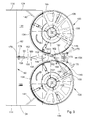
- FIG. 1 shows an agricultural combine harvester 10 with a chassis 12 with ground engaging wheels 14 attached to the chassis 12 for propulsion of the combine 10.
- the operation of the combine 10 is controlled from the operator's cab 16.
- a cutter 18 is used to harvest grain-containing crops and feed it to a feeder 20.
- the harvested good is by the feeder 20 of a Guiding drum 22 fed.
- the guide drum 22 directs the crop through an inlet transition section 24 to an axial Erntegutbearbeitungs owned 26.
- directional information such as front and rear, refer to the forward direction of the combine 10, which in the FIG. 1 goes to the left.
- the crop processor 26 includes a rotor housing 34 and a rotor 36 disposed therein.
- the rotor 36 includes a hollow drum 38 to which crop processing elements are mounted in a feed section 40, a threshing section 42, and a separator section 44.
- the loading section 40 is disposed at the front of the axial crop processing device 26. Longitudinally downstream and rearward of the feed section 40 are the threshing section 42 and the separating section 44.
- the drum 38 is frustoconical in the loading section 40.
- the threshing section 42 includes a frusto-conical front section and a cylindrical rear section.
- At the end of the axial Erntegutbearbeitungsaku 26 is the cylindrical separation portion 44 of the drum 38.
- a tangential threshing drum and at least one axial separation device following her or her following straw walkers can be used.
- Grain and chaff falling through a concave associated with the threshing section 42 and a separating grate associated with the separating section 44 are fed to a cleaning system 28 having a fan 46 and slat screens 48, 50 displaceable in a swinging motion.
- the cleaning system 28 removes the chaff and feeds the clean grain via a screw conveyor 52 to a clean grain elevator (not shown).
- the clean grain elevator deposits the clean grain in a grain tank 30.
- the clean grain in the grain tank 30 may be unloaded by a discharge auger 32 onto a grain cart, trailer or truck.
- Threshed straw leaving the separation section 44 is ejected from the crop processing device 26 through an outlet 62 and fed to an ejection drum 64.
- the cooperating with an underlying bottom 66 ejector drum 64 throws the straw to the rear.
- At the rear of the ejection drum 64 and approximately at a vertical height of its axis of rotation is another conveyor in the form of an overshot working drum conveyor 68.
- the Drum conveyor 68 extends horizontally and transversely to the forward direction and is by a suitable drive about its axis 70, on which it is rotatably mounted on the chassis 12, in a direction of rotation in which he works supersaturated and in the FIG. 1 turns clockwise as indicated by the arrow.
- the drum conveyor 68 corresponds in its construction to the ejection drum 64 and comprises a rotationally symmetrical jacket 72 with drivers 74 mounted around its circumference and rigidly mounted thereon.
- a trough 94 is arranged below the drum conveyor 68.
- a horizontally and forwardly extending upper wall 76 which terminates an overlying engine compartment 78 downwardly.
- a flap 80 at its front, the drum conveyor 68 adjacent end about a horizontally and transversely to the forward direction extending axis 82 is pivoted between a swathing position and a chopping position.
- the flap 80 is angled downwards, as in the FIG. 1 shown, or concavely curved in itself, wherein the radius is adapted to the drum conveyor 68.
- the flap 80 is about the axis 82 between the Hiffselposition in which they in the FIG. 1 shown by solid lines, and a swathing position in which the flap 80 is shown in the figure with dashed lines and it extends above the straw flow to the rear.
- the straw chopper 60 which is comprised of a straw chopper housing 90 and a rotor 92 rotatable transverse to the forward and horizontal axes with brackets 176 welded to the rotor 92 around the circumference of the rotor 92 by bolt 178 (s. FIG. 3 ) pendulum suspended chopping blades 96 composed. Additional throw paddle paddles (not shown) may also be attached to the rotor 92, or some or all of the chopper knives 96 include air handling paddles. Downstream of an outlet 98 of the straw chopper 60 are two side by side below the chute 86 arranged throwing fan 100 is provided, of which in the FIG. 1 only one only recognizable.
- the throwing fans 100 include a number of throwing paddles 102, each rotatable by a respective hydraulic motor 106 about their (approximately vertically extending, but slightly inclined back and forth) axes of rotation 108 and which the straw chopper 60 removes crop residue in the axial direction at an obtuse angle relative to the axes of rotation of the throwing fan 100 from below.
- the axis of rotation 110 of the rotor 92 of the straw chopper 60 extends horizontally and transversely to the forward direction.
- the throwing fans 100 are arranged laterally next to each other at the rear of the straw chopper 60.
- the throwing fans 100 are within the width of the straw chopper 60.
- the throwing blowers 100 are secured by brackets (not shown) to the frame 12 of the combine 10 and / or to the chute 86. It would also be possible to arrange the straw chopper 60 and the throwing fan 100 such that the straw chopper 60 acts on the throwing fan 100 from above.
- the axes of rotation 108 of the throwing fan 100 are horizontal or exactly vertical.
- the straw chopper 60 conveys only the crop residue from the cleaning system 28 to the throwing blowers 100, which distribute it about the width of the cutting unit 18 on the field floor.
- the straw chopper 60 also chops the straw on the outlet 62 of the crop processor 26, which is thrown against the flap 80 by the ejection drum 64 and the drum conveyor 68 and then falls down into the inlet 58 of the straw chopper 60.
- the Erntegutrestehieresel- and -Verteilan inch includes the straw chopper 60 and the throwing fan 100.
- the straw chopper housing 90 includes a bottom 112, two side walls 114 and further cross plates 116, 118, 120, which like the bottom 112 connect the side walls 114 and enclose the rotor 92 ,
- the bottom 112 is disposed on the underside of the straw chopper housing 90 and encloses the enveloping circle defined by the chopping blades 96 circular arc at a relatively small distance with a radius.
- Counter knives (not shown) may also be provided which are secured to the straw chopper housing 90 and penetrate the enveloping circle of the chopper knives 96 to effectively chop the crop debris.
- the ground 112 is followed by a crop residue guide element 122 in the flow direction of the crop residues.
- the Erntegutreste Resultsselement 122 is disposed between side wall extensions 124, which are each connected to a side wall 114 of the straw chopper housing 90 by screw and parallel thereto extend.
- the crop residue guide member 122 is planar in itself (thus has a radius of ⁇ ).
- the crop residue guide member 122 is angled downward at its forward end to form a flange which is bolted to a downwardly angled flange at the rear of the bottom 112. This connection avoids overhanging edges where crop residue could accumulate.
- a cross-plate 126 which bounds the outlet 98 of the straw chopper 60 upwardly.
- a cross plate 116 of the straw chopper housing 90 At the top closes to the cross plate 126 a cross plate 116 of the straw chopper housing 90 at.
- outer vanes 141 On the sidewall extensions 124 are outer vanes 141 (see FIG. FIG. 3 ), which extend at an angle of about 45 ° inwards and backwards.
- an angled bottom plate 128 is arranged, which extends from a position shortly before the axes of rotation to the rear end of the throwing fan 100.
- the floor panel 128 has a forward portion which extends in the plane of the crop residue guide member 122 and abuts a downwardly angled flange of the crop residue guide member 122 with a downwardly angled flange. These flanges can be screwed together or only abut each other to more easily spend the throwing fan 100 separated from the straw chopper 60 in a transport position.
- the front portion of the floor panel 128 extends from said flange to just short of the axis of rotation 108 of the throwing fan 100 and there transitions to a rearward portion which extends below the rearward end of the throwing fan 100 and orthogonal to the axis of rotation 108.
- the lower output shafts 136 of the hydraulic motors 106 mounted on the lid 132 drive the launcher paddles 102 via a cross-link 138 and a cylindrical shaft 139 fixed at its upper end to a plate 130 having a central opening.
- the throw paddles 102 of the throwing fan 100 each extend exactly over the axial dimension of the shaft 139.
- the throwing paddles 102 abut against the plate 130 with their tops or are attached thereto (eg, welded).
- a cover 132 which covers the throwing fan 100 upwards, and on the front side two each a throw fan 100 semicircular forward radially enclosing partial casings 134 are arranged. Further partial sheathings 140 adjoin the adjacent inner sides of the throwing blower 100, wherein gaps 142 remain between the partial sheathings 134 and the partial sheathings 140.
- a two-part guide element 150 which comprises a front part 152 and a rear part 154.
- the front part 152 is attached to the crop residue guide element 122 and with its front tip 156 to the enveloping circle the chopper blade 96 adapted so that it is formed about its the enveloping circle of the chopper 96 adjacent tip 156 circular arc-shaped and this peak 165 is disposed at a relatively small distance from the enveloping circle of the chopper 96.
- the front part 152 forms a slot into which a flat, front plate 158 of the rear part 154 penetrates. Rearward of the front plate 158 widens the rear part 154 and is hollow in itself.
- the rearward portion 154 is secured to the underside of the lid 132 and to the top of the floor panel 128 which, with the sub-shells 134, 140 and additional shields 144, 146, form a throw fan housing.
- passages 162 are present between the guide element 150 and the sub-sheaths 134, 140 of the throwing fan 80, through which a part of the crop residue stream discharged in the middle area of the straw chopper 60 from the straw chopper 60 directly (without cooperating with the throwing fans 100). can flow backwards to the field.
- the partial jackets 140 are, as in the FIGS. 5 to 7 of the EP 2 250 870 A1 is shown, the disclosure of which is incorporated by reference into the present documents, having a higher, rear portion and a lower front portion, between which an obliquely rising portion is provided.
- the partial sheaths 140 may be selectively elongated at their rear ends by shorter or longer angular ranges by controlling first and second circumferentially varying shields 144, 146 by means of a manually controlled by the operator from the cab 16 or automatically depending on the position of the flap 80 Adjustment drive are positioned at the rear ends of the sub-sheaths 140 to divert the crop residues more or less outward by covering the throwing fans 100 and preventing the free delivery of the crop residues radially outwards, so that the crop residues can only leave the throwing fans 100, after passing the shields 144 or 146.
- the shields 144, 146 of both blowers 80 can be adjusted independently of each other to compensate for side wind and / or -hangingefladore.
- a Erntegutleitan extract 164 is provided, which comprises two movable guide members 170 which extend rearwardly to the connect side walls of the rear part 154 of the guide element 150.
- the guide elements 170 form two diverging, respectively outwardly and rearwardly curved walls, which are each arranged adjacent to a throwing blower 100 and terminate in the enveloping circle of the throwing blower 100 or the shields 114, 146.
- the movable guide elements 170 are in each case about a forward axis of rotation 172, which extends parallel to the axis of rotation 108 of the throwing fan 100, displaced by a mounted above the cover 132 drive in a swinging motion, which is now based on the FIGS. 4 and 5 is explained in more detail.
- the guide elements 170 have the task of the output in the central region of the straw chopper 60 crop, which passes directly through the space 162 between the throwing fan 100 partially enclosing Operaummantelept 134, 140 and the guide element 150, and also a part of the throwing fans 100 after deflected back crop in the lateral direction cyclically more or less far laterally outwards and thus distribute evenly on the field.
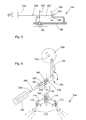
- FIG. 4 shows the drive of Erntegutleit worn 164 in an enlarged view from above.
- the guide elements 170 are pivotally mounted at their front ends about the axes of rotation 172 and there rigidly connected to a forked pivot arm 174.
- the pivot arms 174 extend obliquely forward and inward and their end forks overlap. Both forks of the two pivot arms 174 enclose a pin 180 which extends parallel to the axes of rotation 172 and is attached to a coupling arm 182.
- the coupling arm 182 is further articulated at a pivot point 194 on a gear 184 with adjustable translation, which is designed in the illustrated embodiment as a lever mechanism.
- Lateral guides (not shown) limit the lateral range of motion of the coupling arm 182 in the vicinity of the pin 180.
- a vertical section gear 184 includes a lever member 186 which is rotatably mounted on a pivot axis 188 above the lid 132.
- the lever element 186 is connected by a connecting rod 190 to a drive wheel 196 which can be set into rotation by means of a suitable, in particular hydraulic or electrical or mechanical drive 195, about an axis extending parallel to the axes of rotation 172.
- the connecting rod 190 is articulated eccentrically on the drive wheel 196.
- the drive wheel 196 could also be replaced by a suitable electric or hydraulic linear drive.
- the transmission ratio of the transmission 184 is variable in that the position of the pivot point 194 of the coupling arm 182 on the lever member 186 by an adjustment 198 is variable by the adjustment 198 a pivot pin 200 through which the coupling arm 182 is hinged to the lever member 186 and the pivot point 194, moved along a slot 202 in the lever member 186.
- the adjusting drive 198 is realized in the illustrated embodiment as rigidly attached to the lid 132 hydraulic cylinder, the piston rod is connected by a hinge 204 with a strut 206 which includes at its other end an opening through which the pivot pin 200 extends therethrough.
- the adjusting drive 198 could also comprise an electrically actuated linear drive or a rotating electric or hydraulic motor which displaces the strut 206 or the pivot pin 200 along the slot 202 by means of a spindle drive.
- the adjustment drive 198 can also pivot with the lever element 186 about the pivot axis 188, then eliminates the joint 204 and one has the advantage that the gear ratio does not change continuously during pivoting of the lever member 186.
- the drive wheel 196 rotates about the axis 192 and causes the lever member 186 via the connecting rod 190 in a reciprocating motion, as shown by the arrows in the Figures 3 and 4 illustrated.
- the lever member 186 oscillates about the pivot axis 188 and transmits this movement by the pivot pin 200 on the coupling arm 182, which in turn transmits it via the pin 180 and the forks of the pivot arms 174 on the guide members 170, which thus continuously about the axes of rotation 172nd swing back and forth.
- the transmission ratio of the transmission 184 can be changed: is the pivot pin 200 in the vicinity of the crank rod 190 adjacent end of the slot 202, move the guide members 170 with maximum amplitude (the gear ratio of the transmission 184 is then not quite one ). If, however, the pivot pin 200 is at the other end of the slot 202, so that it is aligned coaxially with the pivot axis 188 of the lever member 186, no movement of the coupling arm 182 takes place more and the guide elements 170 stand still; the gear ratio of the transmission 184 is then zero. In between arbitrary or infinitely many intermediate stages of the transmission ratio of the transmission 184 are possible.
- the coupling arm 182 is moved into its position as far as possible displaced rearwardly, which is due to the fact that the pivot axis 188 is located further back than the slot 202 and thus the other possible positions of the pivot pin 202.
- Die incidentssetti 170 then take that into the Figures 3 and 4 dashed lines, foremost position in which they extend as far as possible forward and outward. In this position, they put the crop residues, especially the Kaff in swath-storage mode, laterally next to the straw swath, so that the latter is not contaminated by Kaff.
- an operator input device 208 is attached, with which the operator can select whether the Erntegutrestehieresel- and -Verteilan whatsoever to be operated in the swath storage mode or in chopping mode.
- An electronic controller 210 connected to the operator input device 208 then adjusts the flap 80 via a suitable actuator, as described above.
- the controller 210 also causes the adjustment drive 198, if the swath-storage mode is selected, to set the ratio of the transmission 184 to zero so that the dump is deposited laterally adjacent to the swath. With the swath storage mode selected, the controller 210 may also disable the drive of the drive wheel 196.
- the controller 210 causes the adjustment drive 198 to adjust the ratio of the transmission 184 to a non-zero, preferably selectable by the operator with the operator input device 208 value and turns on the drive of the drive wheel 196 a.
Abstract
Description
Die Erfindung betrifft eine Erntegutrestehäcksel- und -verteilanordnung für einen Mähdrescher gemäß dem Oberbegriff des Anspruchs 1.The invention relates to a Erntegutrestehäcksel- and -verteilanordnung for a combine harvester according to the preamble of claim. 1
Landwirtschaftliche Mähdrescher sind große Maschinen, die landwirtschaftlich angebautes Erntegut, das Korn trägt, ernten, dreschen, trennen und reinigen. Das erhaltene saubere Korn wird in einem am Mähdrescher angeordneten Korntank gespeichert. Das ausgedroschene Stroh wird, wie beispielsweise in der als gattungsbildend angesehenen
Der Mähdrescher nach
Die
In der
Bei der
Die der Erfindung zu Grunde liegende Aufgabe wird somit darin gesehen, eine Erntegutrestehäcksel - und -verteilanordnung mit einem Strohhäcksler für einen Mähdrescher bereitzustellen, denen durch einen Antrieb kontinuierlich verstellbare Führungselemente zugeordnet sind, die in einem Schwadablagemodus ohne großen Aufwand in eine Stellung verbringbar sind, in welcher sie das durch die Erntegutrestehäcksel- und -verteilanordnung geförderte Kaff seitlich neben dem Schwad ablegen.The object underlying the invention is thus seen in a Erntegutrestehäcksel - and -Verteilanordnung with a straw chopper for a combine harvester, which are assigned by a drive continuously adjustable guide elements, which can be moved in a swath storage mode without much effort in a position in which they funded by the Erntegutrestehäcksel- and -Verteilanordnung Kaff laterally next to the Put down swath.
Diese Aufgabe wird erfindungsgemäß durch die Lehre des Patentanspruches 1 gelöst, wobei in den weiteren Patentansprüchen Merkmale aufgeführt sind, die die Lösung in vorteilhafter Weise weiterentwickeln.This object is achieved by the teaching of claim 1, which are listed in the other claims features that further develop the solution in an advantageous manner.
Eine Erntegutrestehäcksel- und -verteilanordnung für einen Mähdrescher umfasst einen Strohhäcksler. Im Erntebetrieb zerkleinert der Strohhäcksler ihm zugeführte Erntegutreste und führt sie (wenigstens) zwei Führungselementen zu. Die Erntegutrestehäcksel- und -verteilanordnung ist in einem Häckselmodus betreibbar, in welchem das Stroh durch den Strohhäcksler bearbeitet und über das Feld verteilt wird. Außerdem ist die Erntegutrestehäcksel- und -verteilanordnung in einem Schwadablagemodus betreibbar, in dem das Stroh am Strohhäcksler vorbeigeführt wird und die Erntegutrestehäcksel- und -verteilanordnung nur das Kaff fördert und verteilt, wobei das Kaff den Führungselementen über den Strohhäcksler oder unter Umgehung des Strohhäckslers von dem Reinigungssystem zugeführt werden kann.A crop residue chopping and distribution assembly for a combine comprises a straw chopper. In the harvesting operation, the straw chopper crushes crop residue supplied to it and feeds it (at least) to two guide elements. The crop residue chopping and distribution assembly is operable in a chopping mode in which the straw is processed by the straw chopper and distributed throughout the field. In addition, the Erntegutrestehäcksel- and -verteilanordnung is operable in a swath storage mode in which the straw is passed on the straw chopper and the Erntegutrestehäcksel-- and distribution arrangement promotes only the Kaff and distributed, the Kaff the guide elements on the straw chopper or bypassing the straw chopper of the Cleaning system can be supplied.
Die kufenartigen Führungselemente zum seitlichen Ablenken und gleichmäßigen Verteilen der Erntegutreste sind durch einen (rotierenden oder sich hin und her bewegenden) Antrieb in eine kontinuierliche Schwingbewegung versetzbar. Zwischen dem Antrieb und den Führungselementen ist ein Getriebe mit einem verstellbaren Übersetzungsverhältnis angeordnet, welches die Führungselemente bei einem minimalen Übersetzungsverhältnis in eine die Erntegutreste weitestmöglich nach außen leitende Stellung verbringt. Das Getriebe ermöglicht somit, durch Verändern des Übersetzungsverhältnisses die Amplitude der Bewegung der Führungselemente zu verstellen. Bei minimalem Übersetzungsverhältnis ist die Amplitude am kleinsten und vorzugsweise gleich null. Dann befinden sich die Führungselemente in ihrer im größten möglichen Maß nach außen und vorn gerichteten Stellung, in der sie die Erntegutreste nicht in der Nähe der Längsmittelebene des Mähdreschers ablegen, sondern demgegenüber weiter nach außen versetzt.The runner-like guide elements for lateral deflection and even distribution of the crop residues are displaceable by a (rotating or reciprocating) drive in a continuous oscillatory motion. Between the drive and the guide elements, a transmission with an adjustable transmission ratio is arranged, which spends the guide elements at a minimum gear ratio in the crop residues as far as possible outwardly conductive position. The transmission thus makes it possible to adjust the amplitude of the movement of the guide elements by changing the transmission ratio. At minimum gear ratio, the amplitude is smallest, and preferably equal to zero. Then the guide elements are in their greatest possible extent outward and forward position in which they do not place the crop residue in the vicinity of the longitudinal center plane of the combine, but on the other hand, further offset to the outside.
Auf diese Weise kann die Amplitude der Bewegung der Führungselemente stufenlos oder in Stufen verstellt und auf einen der jeweiligen Erntesituation optimal angepassten Wert gebracht werden. Außerdem wird die Möglichkeit geschaffen, die Führungselemente anzuhalten und in eine Stellung zu verbringen, in welcher sie das Kaff seitlich neben dem Schwad ablegen, was insbesondere im Schwadablagemodus von Vorteil ist.In this way, the amplitude of the movement of the guide elements can be adjusted continuously or in steps and brought to a value optimally adapted to the respective crop situation. In addition, the possibility is created to stop the guide elements and to a position spend in which they lay the Kaff side next to the swath, which is particularly advantageous in the swath storage mode.
Vorzugsweise umfasst die Erntegutrestehäcksel- und -verteilanordnung zusätzlich zwei bezüglich der Gutflussrichtung stromab des Strohhäckslers angeordnete Wurfgebläse. Die zu verteilenden, vom Strohhäcksler heran geförderten Erntegutreste werden durch die zwei Wurfgebläse angenommen und über das Feld verteilt. Dazu rotieren die Wurfgebläse gegensinnig, wobei die dem Strohhäcksler zugewandten Bereiche der Wurfgebläse aufeinander zu drehen. Das in Vorwärtsrichtung linke Wurfgebläse rotiert, wenn man es von oben betrachtet, demnach im Uhrzeigersinn, während das in Vorwärtsrichtung rechte Wurfgebläse, von oben her betrachtet, im Gegenuhrzeigersinn rotiert. Rückwärtig der Wurfgebläse und zwischen ihnen sind die Führungselemente jeweils dem Umfang eines der Wurfgebläse benachbart angebracht. Die Führungselemente können die Abrisskante der Wurfgebläse definieren (s.
Die Führungselemente sind vorzugsweise gegensinnig antreibbar. Sie können an ihren vorderen Enden um zumindest näherungsweise vertikal orientierte Drehachsen schwenkbar gelagert sein, obwohl auch eine schwenkbare Lagerung im rückwärtigen Bereich denkbar wäre.The guide elements are preferably driven in opposite directions. They may be pivotally mounted at their front ends about at least approximately vertically oriented axes of rotation, although a pivotable mounting in the rear area would be conceivable.
Der Antrieb der Führungselemente kann durch gegabelte Schwenkarme erfolgen, deren Gabeln einen Stift umgreifen, der an einem verschiebbaren Koppelarm angebracht ist. Es sind aber auch beliebige andere Anordnungen denkbar, wie beispielsweise eine direkte Anlenkung des Koppelarms an einem Führungselement und eine gegensinnige Kraftübertragung von diesem Führungselement bzw. dem Koppelarm auf das andere Führungselement, oder ein gegensinniger Antrieb der Führungselemente durch zwei bewegte Koppelarme, die jeweils ein Führungselement gegenphasig zum anderen Führungselement bewegen.The drive of the guide elements can be done by forked pivot arms whose forks engage around a pin which is attached to a sliding coupling arm. But there are also any other arrangements conceivable, such as a direct articulation of the coupling arm on a guide element and an opposite power transmission from this guide element or the coupling arm on the other guide element, or an opposite drive of the guide elements by two moving coupling arms, each a guide element move in opposite phase to the other guide element.
Das Getriebe umfasst in einer möglichen Ausführungsform der Erfindung ein um eine Schwenkachse schwenkbar gelagertes Hebelelement, das mittels einer mit dem Antrieb gekoppelten Kurbelstange in eine Schwingbewegung versetzbar ist. Ein die Führungselemente mit dem Getriebe verbindender Koppelarm ist gegenüber dem Hebelelement schwenkbar gelagert. Die Position des Schwenkpunkts des Koppelarms am Hebelelement ist durch einen fremdkraftbetätigten Verstellantrieb entlang des Hebelelements verstellbar. Man erhält somit ein Hebelgetriebe mit verstellbarem Übersetzungsverhältnis. Wenn der Koppelarm durch den Verstellantrieb bis in eine zur Schwenkachse des Hebelelements koaxiale Position verbringbar ist, kann das Übersetzungsverhältnis auf null gebracht werden und die Führungselemente kommen dann zum Stehen, obwohl sich der Antrieb noch weiter bewegt und dann ggf. abgeschaltet werden kann. Ist die Schwenkachse des Hebelelements näher an den Führungselementen positioniert als die übrigen Stellungen des Koppelarms am Hebelelement, erreicht man, dass die Führungselemente bei der koaxialen Position des Koppelelements zur Schwenkachse des Hebelelements in ihre weitestmöglich nach vorn verlagerte Position gelangen, in der sie das Erntegut am weitesten nach außen ablenken.In a possible embodiment of the invention, the transmission comprises a lever element which is mounted so as to be pivotable about a pivot axis and which can be set into a swinging movement by means of a connecting rod coupled to the drive. A connecting arm connecting the guide elements to the transmission is pivotally mounted relative to the lever element. The position of the pivot point the coupling arm on the lever element is adjustable by a power-operated adjusting drive along the lever element. One thus obtains a lever mechanism with an adjustable transmission ratio. If the coupling arm can be moved by the adjusting drive into a position coaxial to the pivot axis of the lever element, the transmission ratio can be brought to zero and the guide elements then come to a standstill, although the drive still moves further and then may be switched off. If the pivot axis of the lever element positioned closer to the guide elements than the other positions of the coupling arm on the lever element, it is achieved that the guide elements in the coaxial position of the coupling element to the pivot axis of the lever element in their position displaced as far as possible forward, in which they crop on most distracting to the outside.
Eine von einem Bediener mittels einer Eingabeeinrichtung kontrollierbare elektronische Steuerung kann Aktoren ansteuern, welche geeignete Verstellelemente bewegen, um die Erntegutrestehäcksel - und -verteilanordnung zwischen dem Häckselmodus und dem Schwadablagemodus umzuschalten. Die Steuerung kann auch einen Aktor ansteuern, der im Schwadablagemodus selbsttätig das Getriebe in die Stellung minimaler Übersetzung verbringt.An electronic controller controllable by an operator by means of an input device may drive actuators which move suitable adjustment elements to switch the crop residue chopping and distribution arrangement between the chopping mode and the swathing mode. The controller can also control an actuator, which automatically spends the transmission in the position of minimal translation in the swath-storage mode.
Anhand der Abbildungen wird ein Ausführungsbeispiel der Erfindung erläutert. Es zeigt:
- Fig. 1
- eine teilgeschnittene seitliche Ansicht eines Mähdreschers mit einem Strohhäcksler und Wurfgebläsen,
- Fig. 2
- eine vergrößerte seitliche Ansicht des Strohhäckslers und eines Wurfgebläses,
- Fig. 3
- eine Draufsicht auf den Strohhäcksler und die Wurfgebläse mit stromab angeordneten Führungselementen,
- Fig. 4
- eine vergrößerte Draufsicht auf den Antrieb der Führungselemente und
- Fig. 5
- einen vertikalen Schnitt durch das Getriebe zum Antrieb der Führungselemente.
- Fig. 1
- a partially cutaway side view of a combine harvester with a straw chopper and blowers,
- Fig. 2
- an enlarged side view of the straw chopper and a throwing blower,
- Fig. 3
- a top view of the straw chopper and the throwing fan with downstream guide elements,
- Fig. 4
- an enlarged plan view of the drive of the guide elements and
- Fig. 5
- a vertical section through the gear to drive the guide elements.
Die
Die Erntegutbearbeitungseinrichtung 26 umfasst ein Rotorgehäuse 34 und einen darin angeordneten Rotor 36. Der Rotor 36 umfasst eine hohle Trommel 38, an der Gutbearbeitungselemente in einem Beschickungsabschnitt 40, einen Dreschabschnitt 42 und einen Trennabschnitt 44 befestigt sind. Der Beschickungsabschnitt 40 ist an der Vorderseite der axialen Erntegutbearbeitungseinrichtung 26 angeordnet. In Längsrichtung stromab und rückwärtig des Beschickungsabschnitts 40 liegen der Dreschabschnitt 42 und der Trennabschnitt 44. Die Trommel 38 ist im Beschickungsabschnitt 40 kegelstumpfförmig. Der Dreschabschnitt 42 umfasst einen kegelstumpfförmigen vorderen Abschnitt und einen zylindrischen rückwärtigen Abschnitt. Am Ende der axialen Erntegutbearbeitungseinheit 26 befindet sich der zylindrische Trennabschnitt 44 der Trommel 38. Anstelle einer axialen Erntegutbearbeitungseinheit 26 können auch eine tangentiale Dreschtrommel und wenigstens eine ihr folgende axiale Trenneinrichtung oder ihr folgende Strohschüttler verwendet werden.The
Korn und Spreu, die durch einen dem Dreschabschnitt 42 zugeordneten Dreschkorb und ein dem Trennabschnitt 44 zugeordneten Trennrost fallen, werden einem Reinigungssystem 28 mit einem Gebläse 46 und in eine Schwingbewegung versetzbaren Lamellensieben 48, 50 zugeführt. Das Reinigungssystem 28 entfernt die Spreu und führt das saubere Korn über einen Schneckenförderer 52 einem Elevator für sauberes Korn (nicht gezeigt) zu. Der Elevator für sauberes Korn legt das saubere Korn in einem Korntank 30 ab. Das saubere Korn im Korntank 30 kann durch einen Entladeschneckenförderer 32 auf einen Kornwagen, Anhänger oder Lastwagen entladen werden. Am rückwärtigen Ende des unteren Lamellensiebs 50 verbleibendes Erntegut wird mittels eines Schneckenförderers 54 und eines Überkehrförderers (nicht gezeigt) wieder der Erntegutbearbeitungseinrichtung 26 oder einem separaten Nachdrescher zugeführt, der es dann wieder dem Reinigungssystem 28 zuführt. Die am rückwärtigen Ende des oberen Lamellensiebs 48 abgegebenen Erntegutreste, die im Wesentlichen aus Kaff (Spreu) und kleinen Strohteilchen bestehen, werden durch einen Schwingbodenförderer 56 nach hinten in einen Einlass 58 eines Strohhäckslers 60 gefördert.Grain and chaff falling through a concave associated with the threshing
Gedroschenes, den Trennabschnitt 44 verlassendes Stroh wird durch einen Auslass 62 aus der Erntegutbearbeitungseinrichtung 26 ausgestoßen und einer Auswurftrommel 64 zugeführt. Die mit einem darunter angeordneten Boden 66 zusammenwirkende Auswurftrommel 64 wirft das Stroh nach hinten aus. Rückwärtig der Auswurftrommel 64 und etwa in vertikaler Höhe ihrer Drehachse befindet sich ein weiterer Förderer in Form eines oberschlächtig arbeitenden Trommelförderers 68. Der Trommelförderer 68 erstreckt sich horizontal und quer zur Vorwärtsrichtung und ist durch einen geeigneten Antrieb um seine Achse 70, an der er drehbar am Fahrgestell 12 befestigt ist, in eine Drehrichtung in Drehung versetzbar, in der er oberschlächtig arbeitet und in der
Oberhalb der Auswurftrommel 64 und des Trommelförderers 68 ist eine sich horizontal und in Vorwärtsrichtung erstreckende obere Wand 76 angebracht, die einen darüber befindlichen Motorraum 78 nach unten abschließt. An der Wand 76 ist eine Klappe 80 an ihrem vorderen, dem Trommelförderer 68 benachbarten Ende um eine sich horizontal und quer zur Vorwärtsrichtung erstreckende Achse 82 zwischen einer Schwadablageposition und einer Häckselposition verschwenkbar angelenkt. Die Klappe 80 ist nach unten abgewinkelt, wie in der
Unterhalb des unteren und rückwärtigen Endes der Klappe 80 schließt sich (bei in der Häckselstellung befindlicher Klappe 80) lückenlos ein mit dem Fahrgestell 12 fest verbundenes Blech 84 an, das sich schräg nach hinten und unten erstreckt und mit einer sich daran anschließenden Rutsche 86 verbunden ist, auf der das Stroh im Schwadablagebetrieb nach unten auf den Feldboden gleiten kann. Das Strohschwad kann noch durch an der Oberseite der Rutsche 86 angebrachte Leitkufen oder Strohleitrechen (nicht gezeigt) in eine gewünschte Form gebracht werden.Below the lower and rear end of the
Die Klappe 80 ist um die Achse 82 zwischen der Häckselposition, in der sie in der
Unterhalb des Blechs 84 befindet sich der Strohhäcksler 60, der sich aus einem Strohhäckslergehäuse 90 und einem darin angeordneten, um eine quer zur Vorwärtsrichtung und horizontal verlaufende Achse drehbaren Rotor 92 mit um den Umfang des Rotors 92 verteilten, an mit dem Rotor 92 verschweißten Konsolen 176 durch Schraubbolzen 178 (s.
Die Drehachse 110 des Rotors 92 des Strohhäckslers 60 erstreckt sich horizontal und quer zur Vorwärtsrichtung. Die Wurfgebläse 100 sind seitlich nebeneinander rückwärtig des Strohhäckslers 60 angeordnet. Die Wurfgebläse 100 befinden sich innerhalb der Breite des Strohhäckslers 60. Die Wurfgebläse 100 sind durch Halterungen (nicht gezeigt) am dem Rahmen 12 des Mähdreschers 10 und/oder an der Rutsche 86 befestigt. Es wäre auch möglich, den Strohhäcksler 60 und die Wurfgebläse 100 derart anzuordnen, dass der Strohhäcksler 60 die Wurfgebläse 100 von oben her beaufschlagt. Bei einer anderen Ausführungsform sind die Drehachsen 108 der Wurfgebläse 100 horizontal oder genau vertikal.The axis of
In der Schwadablageposition der Klappe 80 fördert der Strohhäcksler 60 nur die Erntegutreste aus dem Reinigungssystem 28 zu den Wurfgebläsen 100, welche sie etwa über die Breite des Schneidwerks 18 auf dem Feldboden verteilen. Im Häckselbetrieb zerkleinert der Strohhäcksler 60 auch das Stroh auf dem Auslass 62 der Erntegutbearbeitungseinrichtung 26, das durch die Auswurftrommel 64 und den Trommelförderer 68 gegen die Klappe 80 geworfen wird und dann nach unten in den Einlass 58 des Strohhäckslers 60 fällt.In the swathing position of the
Es wird nun auf die
An den Boden 112 schließt sich in der Flussrichtung der Erntegutreste ein Erntegutresteführungselement 122 an. Das Erntegutresteführungselement 122 ist zwischen Seitenwandverlängerungen 124 angeordnet, die mit je einer Seitenwand 114 des Strohhäckslergehäuses 90 durch Schraubverbindungen verbunden sind und sich dazu parallel erstrecken. Das Erntegutresteführungselement 122 ist in sich eben (hat demnach einen Radius von ∞). Das Erntegutresteführungselement 122 ist an seinem vorderen Ende nach unten abgewinkelt, um einen Flansch zu bilden, der mit einem ebenfalls nach unten abgewinkelten Flansch an der Rückseite des Bodens 112 verschraubt ist. Durch diese Verbindung vermeidet man überstehende Kanten, an denen sich Erntegutreste ansammeln könnten. An der Oberseite der Seitenwandverlängerungen 124 ist ein Querblech 126 angebracht, das den Auslass 98 des Strohhäckslers 60 nach oben hin begrenzt. Nach oben hin schließt sich an das Querblech 126 ein Querblech 116 des Strohhäckslergehäuses 90 an. An den Seitenwandverlängerungen 124 sind äußere Leitelemente 141 (s.
An der Unterseite der Wurfgebläse 100 ist ein abgewinkeltes Bodenblech 128 angeordnet, das sich von einer Position kurz vor den Drehachsen bis an das rückwärtige Ende der Wurfgebläse 100 erstreckt. Das Bodenblech 128 weist einen vorderen Abschnitt auf, der sich in der Ebene des Erntegutresteführungselements 122 erstreckt und mit einem nach unten abgewinkelten Flansch an einem nach unten abgewinkelten Flansch des Erntegutresteführungselements 122 anliegt. Diese Flansche können miteinander verschraubt werden oder nur aneinander anliegen, um die Wurfgebläse 100 leichter getrennt vom Strohhäcksler 60 in eine Transportposition verbringen zu können. Der vordere Abschnitt des Bodenblechs 128 erstreckt sich vom besagten Flansch bis kurz vor die Drehachse 108 der Wurfgebläse 100 und geht dort in einen rückwärtigen Abschnitt über, der sich bis unter das rückwärtige Ende der Wurfgebläse 100 und orthogonal zur Drehachse 108 erstreckt.On the underside of the throwing
Die unten liegenden Ausgangswellen 136 der am Deckel 132 befestigten Hydromotoren 106 treiben die Wurfpaddel 102 über eine Querverbindung 138 und eine zylindrische Welle 139 an, die an ihrem oberen Ende an einem Teller 130 mit einer mittleren Öffnung befestigt ist. Die Wurfpaddel 102 der Wurfgebläse 100 erstrecken sich jeweils genau über die axiale Abmessung der Welle 139. Die Wurfpaddel 102 liegen mit ihren Oberseiten am Teller 130 an oder sind daran befestigt (z. B. angeschweißt).The
Oberhalb des Tellers 130 befindet sich ein Deckel 132, der die Wurfgebläse 100 nach oben hin abdeckt, und an dessen Vorderseite zwei jeweils ein Wurfgebläse 100 halbkreisförmig nach vorn radial umschließende Teilummantelungen 134 angeordnet sind. Weitere Teilummantelungen 140 schließen sich an den benachbarten Innenseiten der Wurfgebläse 100 an, wobei zwischen den Teilummantelungen 134 und den Teilummantelungen 140 noch Lücken 142 verbleiben.Above the
Zwischen den beiden Wurfgebläsen 100 befindet sich ein zweiteiliges Leitelement 150, das einen vorderen Teil 152 und einen rückwärtigen Teil 154 umfasst. Der vordere Teil 152 ist am Erntegutresteführungselement 122 befestigt und mit seiner vorderen Spitze 156 an den Hüllkreis der Häckselmesser 96 angepasst, so dass er über seine dem Hüllkreis der Häckselmesser 96 benachbarte Spitze 156 kreisbogenförmig ausgeformt ist und diese Spitze 165 in einem relativ geringen Abstand vom Hüllkreis der Häckselmesser 96 angeordnet ist. An seiner Rückseite bildet der vordere Teil 152 einen Schlitz, in den ein flaches, vorderes Blech 158 des rückwärtigen Teils 154 eindringt. Rückwärtig des vorderen Blechs 158 verbreitert sich der rückwärtige Teil 154 und ist in sich hohl. Der rückwärtige Teil 154 ist an der Unterseite des Deckels 132 und an der Oberseite des Bodenblechs 128 befestigt, welche mit den Teilummantelungen 134, 140 und zusätzlichen Abschirmungen 144, 146 ein Wurfgebläsegehäuse bilden.Between the two throwing
Anhand der
Die Teilummantelungen 140 sind, wie in den
Rückwärtig des rückwärtigen Teils 154 des Leitelements 150 ist eine Erntegutleitanordnung 164 vorgesehen, die zwei bewegliche Führungselemente 170 umfasst, die sich nach hinten an die seitlichen Wände des rückwärtigen Teils 154 des Leitelements 150 anschließen. Die Führungselemente 170 bilden zwei divergierende, jeweils nach außen und hinten gekrümmte Wände, die jeweils einem Wurfgebläse 100 benachbart angeordnet sind und sich an den Hüllkreis der Wurfgebläse 100 bzw. der Abschirmungen 114, 146 abschließen. Die beweglichen Führungselemente 170 sind jeweils um eine vorn liegende Drehachse 172, die sich parallel zur Drehachse 108 der Wurfgebläse 100 erstreckt, durch einen oberhalb des Deckels 132 angebrachten Antrieb in eine Schwingbewegung versetzbar, der nun anhand der
Die
Das in der
Der Verstellantrieb 198 ist in der dargestellten Ausführungsform als starr am Deckel 132 befestigter Hydraulikzylinder realisiert, dessen Kolbenstange durch ein Gelenk 204 mit einer Strebe 206 verbunden ist, die an ihrem anderen Ende eine Öffnung umfasst, durch welche sich der Schwenkstift 200 hindurch erstreckt. Anstelle eines Hydraulikzylinders könnte der Verstellantrieb 198 auch einen elektrisch betätigten Linearantrieb oder einen rotierenden Elektro - oder Hydraulikmotor umfassen, der die Strebe 206 bzw. den Schwenkstift 200 mittels eines Spindeltriebes entlang des Langlochs 202 verstellt. Anders als dargestellt kann der Verstellantrieb 198 auch mit dem Hebelelement 186 um die Schwenkachse 188 verschwenken, dann entfällt das Gelenk 204 und man hat den Vorteil, dass sich das Übersetzungsverhältnis nicht beim Schwenken des Hebelelements 186 kontinuierlich ändert.The adjusting
Im Betrieb dreht sich das Antriebsrad 196 um die Achse 192 und versetzt das Hebelelement 186 über die Kurbelstange 190 in eine Hin- und Herbewegung, wie durch die Pfeile in den
Bei einem Übersetzungsverhältnis von null wird der Koppelarm 182 in seine weitest möglich nach hinten verlagerte Stellung verbracht, was dadurch bedingt ist, dass sich die Schwenkachse 188 weiter hinten befindet als das Langloch 202 und somit die anderen, möglichen Stellungen des Schwenkstifts 202. Die Führungselemente 170 nehmen dann die in den
In der Kabine 16 ist eine Bedienereingabeeinrichtung 208 angebracht, mit welcher der Bediener auswählen kann, ob die Erntegutrestehäcksel- und -verteilanordnung im Schwadablagemodus oder im Häckselmodus betrieben werden soll. Eine mit der Bedienereingabeeinrichtung 208 verbundene, elektronische Steuerung 210 (vgl.
Claims (10)
Applications Claiming Priority (1)
| Application Number | Priority Date | Filing Date | Title |
|---|---|---|---|
| DE201210206688 DE102012206688A1 (en) | 2012-04-24 | 2012-04-24 | Erntegutrestehäcksel- and -Verteilanordnung for a combine harvester with be brought into a swathing position guide elements |
Publications (3)
| Publication Number | Publication Date |
|---|---|
| EP2656723A2 true EP2656723A2 (en) | 2013-10-30 |
| EP2656723A3 EP2656723A3 (en) | 2014-11-26 |
| EP2656723B1 EP2656723B1 (en) | 2016-01-06 |
Family
ID=48013760
Family Applications (1)
| Application Number | Title | Priority Date | Filing Date |
|---|---|---|---|
| EP13159960.7A Active EP2656723B1 (en) | 2012-04-24 | 2013-03-19 | Harvested goods remnant shredder and distribution assembly for an agricultural harvester with guiding elements that can be brought into a swath discharge position |
Country Status (2)
| Country | Link |
|---|---|
| EP (1) | EP2656723B1 (en) |
| DE (1) | DE102012206688A1 (en) |
Cited By (1)
| Publication number | Priority date | Publication date | Assignee | Title |
|---|---|---|---|---|
| CN114766204A (en) * | 2022-04-12 | 2022-07-22 | 中机美诺科技股份有限公司 | Green feed harvester transmission system |
Citations (4)
| Publication number | Priority date | Publication date | Assignee | Title |
|---|---|---|---|---|
| DE10029715A1 (en) | 2000-06-16 | 2002-01-03 | Deere & Co | Distribution device for a shredding device |
| EP1219164A1 (en) | 2000-12-21 | 2002-07-03 | CLAAS Selbstfahrende Erntemaschinen GmbH | Method and device for conveying crop in an agricultural machine |
| DE10133965A1 (en) | 2001-07-17 | 2003-02-13 | Claas Selbstfahr Erntemasch | Combine harvester with associated chopper and connected blower |
| EP2250870A1 (en) | 2009-05-14 | 2010-11-17 | Deere & Company | Harvested goods remnant shredder and distribution assembly for a combine harvester |
Family Cites Families (4)
| Publication number | Priority date | Publication date | Assignee | Title |
|---|---|---|---|---|
| DE4313841A1 (en) * | 1993-04-27 | 1994-11-03 | Biso Maschf Gmbh | Combine harvester |
| SE9803556L (en) * | 1998-10-16 | 1999-08-09 | Rekordverken Ab | Device for cutting machine with adjustable spreading vanes |
| DE102007043524A1 (en) * | 2007-09-12 | 2009-03-19 | Claas Selbstfahrende Erntemaschinen Gmbh | Combine harvester with straw chopper |
| DE102009028765A1 (en) * | 2009-05-14 | 2010-11-25 | Deere & Company, Moline | Harvest crop shred and distribution arrangement for a combine harvester |
-
2012
- 2012-04-24 DE DE201210206688 patent/DE102012206688A1/en not_active Withdrawn
-
2013
- 2013-03-19 EP EP13159960.7A patent/EP2656723B1/en active Active
Patent Citations (4)
| Publication number | Priority date | Publication date | Assignee | Title |
|---|---|---|---|---|
| DE10029715A1 (en) | 2000-06-16 | 2002-01-03 | Deere & Co | Distribution device for a shredding device |
| EP1219164A1 (en) | 2000-12-21 | 2002-07-03 | CLAAS Selbstfahrende Erntemaschinen GmbH | Method and device for conveying crop in an agricultural machine |
| DE10133965A1 (en) | 2001-07-17 | 2003-02-13 | Claas Selbstfahr Erntemasch | Combine harvester with associated chopper and connected blower |
| EP2250870A1 (en) | 2009-05-14 | 2010-11-17 | Deere & Company | Harvested goods remnant shredder and distribution assembly for a combine harvester |
Cited By (2)
| Publication number | Priority date | Publication date | Assignee | Title |
|---|---|---|---|---|
| CN114766204A (en) * | 2022-04-12 | 2022-07-22 | 中机美诺科技股份有限公司 | Green feed harvester transmission system |
| CN114766204B (en) * | 2022-04-12 | 2024-01-23 | 中机美诺科技股份有限公司 | Transmission system of green fodder harvester |
Also Published As
| Publication number | Publication date |
|---|---|
| DE102012206688A1 (en) | 2013-10-24 |
| EP2656723A3 (en) | 2014-11-26 |
| EP2656723B1 (en) | 2016-01-06 |
Similar Documents
| Publication | Publication Date | Title |
|---|---|---|
| EP2250870B1 (en) | Harvested goods remnant shredder and distribution assembly for a combine harvester | |
| EP2250868B1 (en) | Harvested goods residue shredder and distribution assembly for a combine harvester | |
| EP2175710B1 (en) | Harvester comprising an additional drum conveyor for conveying straw and a single flap for changing between swath deposit and shredding operation | |
| EP2022310B1 (en) | Harvested material release assembly for a combine harvester which can be switched between wide distribution and emission manifold operation | |
| EP2286655B1 (en) | Harvested goods remnant shredder and distribution assembly for a combine harvester | |
| EP2250869B1 (en) | Harvested goods remnant shredder and distribution assembly for a combine harvester | |
| DE102007037485B3 (en) | Agricultural chopping and distributing device comprises a material separating element which can be displaced in a continuous lateral pivoting movement using a drive unit | |
| EP2286654B1 (en) | Harvested goods remnant shredder and distribution assembly for a combine harvester | |
| EP1074176A1 (en) | Straw chopper | |
| EP2810549A1 (en) | Combine harvester | |
| EP2232976B1 (en) | Harvested goods remnant shredder and distribution assembly for a combine harvester | |
| EP3150060B1 (en) | Chaff chopper for a combine harvester with counter-blades and rub bar | |
| EP2656723B1 (en) | Harvested goods remnant shredder and distribution assembly for an agricultural harvester with guiding elements that can be brought into a swath discharge position | |
| EP3338527A1 (en) | Combine harvester | |
| DE102008040125B4 (en) | Combine harvester with an additional straw conveying conveyor | |
| DE102008040119B4 (en) | Combine harvester with a drums conveyor drivable in different directions of rotation for changing between swathing operation and chopping operation | |
| DE102017222409A1 (en) | Arrangement for switching a combine to change between swathing and Breitverteilbetrieb | |
| EP1530895B1 (en) | Combined harvester stone trap | |
| DE102005048052A1 (en) | Crop residue distributing machine for combine harvester, has means for successive discharge of crop residue over its length and two halves of crop residue distributing machine are arranged on both sides along mid-plane of combine harvester | |
| DE102008040128B4 (en) | Erntegutrestehäcksel and -istribution arrangement for a combine harvester with a matched to the contour of the straw chopper throwing fan | |
| BE1023629B1 (en) | Crop residue distribution device for a combine harvester | |
| DE102008040116B4 (en) | Combine harvester with an endless conveyor and a baffle movable between a swath-depositing position and a chopping position |
Legal Events
| Date | Code | Title | Description |
|---|---|---|---|
| PUAI | Public reference made under article 153(3) epc to a published international application that has entered the european phase |
Free format text: ORIGINAL CODE: 0009012 |
|
| AK | Designated contracting states |
Kind code of ref document: A2 Designated state(s): AL AT BE BG CH CY CZ DE DK EE ES FI FR GB GR HR HU IE IS IT LI LT LU LV MC MK MT NL NO PL PT RO RS SE SI SK SM TR |
|
| AX | Request for extension of the european patent |
Extension state: BA ME |
|
| PUAL | Search report despatched |
Free format text: ORIGINAL CODE: 0009013 |
|
| AK | Designated contracting states |
Kind code of ref document: A3 Designated state(s): AL AT BE BG CH CY CZ DE DK EE ES FI FR GB GR HR HU IE IS IT LI LT LU LV MC MK MT NL NO PL PT RO RS SE SI SK SM TR |
|
| AX | Request for extension of the european patent |
Extension state: BA ME |
|
| RIC1 | Information provided on ipc code assigned before grant |
Ipc: A01D 41/12 20060101AFI20141021BHEP |
|
| 17P | Request for examination filed |
Effective date: 20150526 |
|
| RBV | Designated contracting states (corrected) |
Designated state(s): AL AT BE BG CH CY CZ DE DK EE ES FI FR GB GR HR HU IE IS IT LI LT LU LV MC MK MT NL NO PL PT RO RS SE SI SK SM TR |
|
| GRAP | Despatch of communication of intention to grant a patent |
Free format text: ORIGINAL CODE: EPIDOSNIGR1 |
|
| INTG | Intention to grant announced |
Effective date: 20150729 |
|
| GRAS | Grant fee paid |
Free format text: ORIGINAL CODE: EPIDOSNIGR3 |
|
| GRAA | (expected) grant |
Free format text: ORIGINAL CODE: 0009210 |
|
| AK | Designated contracting states |
Kind code of ref document: B1 Designated state(s): AL AT BE BG CH CY CZ DE DK EE ES FI FR GB GR HR HU IE IS IT LI LT LU LV MC MK MT NL NO PL PT RO RS SE SI SK SM TR |
|
| REG | Reference to a national code |
Ref country code: GB Ref legal event code: FG4D Free format text: NOT ENGLISH |
|
| REG | Reference to a national code |
Ref country code: CH Ref legal event code: EP |
|
| REG | Reference to a national code |
Ref country code: IE Ref legal event code: FG4D Free format text: LANGUAGE OF EP DOCUMENT: GERMAN |
|
| REG | Reference to a national code |
Ref country code: AT Ref legal event code: REF Ref document number: 767989 Country of ref document: AT Kind code of ref document: T Effective date: 20160215 |
|
| REG | Reference to a national code |
Ref country code: DE Ref legal event code: R096 Ref document number: 502013001731 Country of ref document: DE |
|
| REG | Reference to a national code |
Ref country code: SE Ref legal event code: TRGR |
|
| REG | Reference to a national code |
Ref country code: LT Ref legal event code: MG4D |
|
| REG | Reference to a national code |
Ref country code: NL Ref legal event code: MP Effective date: 20160106 |
|
| PG25 | Lapsed in a contracting state [announced via postgrant information from national office to epo] |
Ref country code: NL Free format text: LAPSE BECAUSE OF FAILURE TO SUBMIT A TRANSLATION OF THE DESCRIPTION OR TO PAY THE FEE WITHIN THE PRESCRIBED TIME-LIMIT Effective date: 20160106 |
|
| PG25 | Lapsed in a contracting state [announced via postgrant information from national office to epo] |
Ref country code: IT Free format text: LAPSE BECAUSE OF FAILURE TO SUBMIT A TRANSLATION OF THE DESCRIPTION OR TO PAY THE FEE WITHIN THE PRESCRIBED TIME-LIMIT Effective date: 20160106 Ref country code: NO Free format text: LAPSE BECAUSE OF FAILURE TO SUBMIT A TRANSLATION OF THE DESCRIPTION OR TO PAY THE FEE WITHIN THE PRESCRIBED TIME-LIMIT Effective date: 20160406 Ref country code: HR Free format text: LAPSE BECAUSE OF FAILURE TO SUBMIT A TRANSLATION OF THE DESCRIPTION OR TO PAY THE FEE WITHIN THE PRESCRIBED TIME-LIMIT Effective date: 20160106 Ref country code: ES Free format text: LAPSE BECAUSE OF FAILURE TO SUBMIT A TRANSLATION OF THE DESCRIPTION OR TO PAY THE FEE WITHIN THE PRESCRIBED TIME-LIMIT Effective date: 20160106 Ref country code: GR Free format text: LAPSE BECAUSE OF FAILURE TO SUBMIT A TRANSLATION OF THE DESCRIPTION OR TO PAY THE FEE WITHIN THE PRESCRIBED TIME-LIMIT Effective date: 20160407 Ref country code: FI Free format text: LAPSE BECAUSE OF FAILURE TO SUBMIT A TRANSLATION OF THE DESCRIPTION OR TO PAY THE FEE WITHIN THE PRESCRIBED TIME-LIMIT Effective date: 20160106 |
|
| PG25 | Lapsed in a contracting state [announced via postgrant information from national office to epo] |
Ref country code: LT Free format text: LAPSE BECAUSE OF FAILURE TO SUBMIT A TRANSLATION OF THE DESCRIPTION OR TO PAY THE FEE WITHIN THE PRESCRIBED TIME-LIMIT Effective date: 20160106 Ref country code: PT Free format text: LAPSE BECAUSE OF FAILURE TO SUBMIT A TRANSLATION OF THE DESCRIPTION OR TO PAY THE FEE WITHIN THE PRESCRIBED TIME-LIMIT Effective date: 20160506 Ref country code: RS Free format text: LAPSE BECAUSE OF FAILURE TO SUBMIT A TRANSLATION OF THE DESCRIPTION OR TO PAY THE FEE WITHIN THE PRESCRIBED TIME-LIMIT Effective date: 20160106 Ref country code: LV Free format text: LAPSE BECAUSE OF FAILURE TO SUBMIT A TRANSLATION OF THE DESCRIPTION OR TO PAY THE FEE WITHIN THE PRESCRIBED TIME-LIMIT Effective date: 20160106 Ref country code: IS Free format text: LAPSE BECAUSE OF FAILURE TO SUBMIT A TRANSLATION OF THE DESCRIPTION OR TO PAY THE FEE WITHIN THE PRESCRIBED TIME-LIMIT Effective date: 20160506 Ref country code: PL Free format text: LAPSE BECAUSE OF FAILURE TO SUBMIT A TRANSLATION OF THE DESCRIPTION OR TO PAY THE FEE WITHIN THE PRESCRIBED TIME-LIMIT Effective date: 20160106 |
|
| REG | Reference to a national code |
Ref country code: DE Ref legal event code: R097 Ref document number: 502013001731 Country of ref document: DE |
|
| PG25 | Lapsed in a contracting state [announced via postgrant information from national office to epo] |
Ref country code: LU Free format text: LAPSE BECAUSE OF FAILURE TO SUBMIT A TRANSLATION OF THE DESCRIPTION OR TO PAY THE FEE WITHIN THE PRESCRIBED TIME-LIMIT Effective date: 20160319 Ref country code: EE Free format text: LAPSE BECAUSE OF FAILURE TO SUBMIT A TRANSLATION OF THE DESCRIPTION OR TO PAY THE FEE WITHIN THE PRESCRIBED TIME-LIMIT Effective date: 20160106 Ref country code: DK Free format text: LAPSE BECAUSE OF FAILURE TO SUBMIT A TRANSLATION OF THE DESCRIPTION OR TO PAY THE FEE WITHIN THE PRESCRIBED TIME-LIMIT Effective date: 20160106 Ref country code: MC Free format text: LAPSE BECAUSE OF FAILURE TO SUBMIT A TRANSLATION OF THE DESCRIPTION OR TO PAY THE FEE WITHIN THE PRESCRIBED TIME-LIMIT Effective date: 20160106 |
|
| REG | Reference to a national code |
Ref country code: CH Ref legal event code: PL |
|
| PLBE | No opposition filed within time limit |
Free format text: ORIGINAL CODE: 0009261 |
|
| STAA | Information on the status of an ep patent application or granted ep patent |
Free format text: STATUS: NO OPPOSITION FILED WITHIN TIME LIMIT |
|
| PG25 | Lapsed in a contracting state [announced via postgrant information from national office to epo] |
Ref country code: RO Free format text: LAPSE BECAUSE OF FAILURE TO SUBMIT A TRANSLATION OF THE DESCRIPTION OR TO PAY THE FEE WITHIN THE PRESCRIBED TIME-LIMIT Effective date: 20160106 Ref country code: CZ Free format text: LAPSE BECAUSE OF FAILURE TO SUBMIT A TRANSLATION OF THE DESCRIPTION OR TO PAY THE FEE WITHIN THE PRESCRIBED TIME-LIMIT Effective date: 20160106 Ref country code: SK Free format text: LAPSE BECAUSE OF FAILURE TO SUBMIT A TRANSLATION OF THE DESCRIPTION OR TO PAY THE FEE WITHIN THE PRESCRIBED TIME-LIMIT Effective date: 20160106 Ref country code: SM Free format text: LAPSE BECAUSE OF FAILURE TO SUBMIT A TRANSLATION OF THE DESCRIPTION OR TO PAY THE FEE WITHIN THE PRESCRIBED TIME-LIMIT Effective date: 20160106 |
|
| 26N | No opposition filed |
Effective date: 20161007 |
|
| REG | Reference to a national code |
Ref country code: IE Ref legal event code: MM4A |
|
| REG | Reference to a national code |
Ref country code: FR Ref legal event code: ST Effective date: 20161130 |
|
| PG25 | Lapsed in a contracting state [announced via postgrant information from national office to epo] |
Ref country code: CH Free format text: LAPSE BECAUSE OF NON-PAYMENT OF DUE FEES Effective date: 20160331 Ref country code: IE Free format text: LAPSE BECAUSE OF NON-PAYMENT OF DUE FEES Effective date: 20160319 Ref country code: FR Free format text: LAPSE BECAUSE OF NON-PAYMENT OF DUE FEES Effective date: 20160331 Ref country code: LI Free format text: LAPSE BECAUSE OF NON-PAYMENT OF DUE FEES Effective date: 20160331 |
|
| PG25 | Lapsed in a contracting state [announced via postgrant information from national office to epo] |
Ref country code: SI Free format text: LAPSE BECAUSE OF FAILURE TO SUBMIT A TRANSLATION OF THE DESCRIPTION OR TO PAY THE FEE WITHIN THE PRESCRIBED TIME-LIMIT Effective date: 20160106 Ref country code: BG Free format text: LAPSE BECAUSE OF FAILURE TO SUBMIT A TRANSLATION OF THE DESCRIPTION OR TO PAY THE FEE WITHIN THE PRESCRIBED TIME-LIMIT Effective date: 20160406 |
|
| PG25 | Lapsed in a contracting state [announced via postgrant information from national office to epo] |
Ref country code: MT Free format text: LAPSE BECAUSE OF FAILURE TO SUBMIT A TRANSLATION OF THE DESCRIPTION OR TO PAY THE FEE WITHIN THE PRESCRIBED TIME-LIMIT Effective date: 20160106 |
|
| GBPC | Gb: european patent ceased through non-payment of renewal fee |
Effective date: 20170319 |
|
| PG25 | Lapsed in a contracting state [announced via postgrant information from national office to epo] |
Ref country code: GB Free format text: LAPSE BECAUSE OF NON-PAYMENT OF DUE FEES Effective date: 20170319 |
|
| PG25 | Lapsed in a contracting state [announced via postgrant information from national office to epo] |
Ref country code: CY Free format text: LAPSE BECAUSE OF FAILURE TO SUBMIT A TRANSLATION OF THE DESCRIPTION OR TO PAY THE FEE WITHIN THE PRESCRIBED TIME-LIMIT Effective date: 20160106 Ref country code: HU Free format text: LAPSE BECAUSE OF FAILURE TO SUBMIT A TRANSLATION OF THE DESCRIPTION OR TO PAY THE FEE WITHIN THE PRESCRIBED TIME-LIMIT; INVALID AB INITIO Effective date: 20130319 |
|
| PG25 | Lapsed in a contracting state [announced via postgrant information from national office to epo] |
Ref country code: MK Free format text: LAPSE BECAUSE OF FAILURE TO SUBMIT A TRANSLATION OF THE DESCRIPTION OR TO PAY THE FEE WITHIN THE PRESCRIBED TIME-LIMIT Effective date: 20160106 Ref country code: TR Free format text: LAPSE BECAUSE OF FAILURE TO SUBMIT A TRANSLATION OF THE DESCRIPTION OR TO PAY THE FEE WITHIN THE PRESCRIBED TIME-LIMIT Effective date: 20160106 |
|
| PG25 | Lapsed in a contracting state [announced via postgrant information from national office to epo] |
Ref country code: AL Free format text: LAPSE BECAUSE OF FAILURE TO SUBMIT A TRANSLATION OF THE DESCRIPTION OR TO PAY THE FEE WITHIN THE PRESCRIBED TIME-LIMIT Effective date: 20160106 |
|
| PGFP | Annual fee paid to national office [announced via postgrant information from national office to epo] |
Ref country code: HU Payment date: 20190318 Year of fee payment: 16 Ref country code: SE Payment date: 20190326 Year of fee payment: 7 |
|
| REG | Reference to a national code |
Ref country code: AT Ref legal event code: MM01 Ref document number: 767989 Country of ref document: AT Kind code of ref document: T Effective date: 20200319 |
|
| PG25 | Lapsed in a contracting state [announced via postgrant information from national office to epo] |
Ref country code: SE Free format text: LAPSE BECAUSE OF NON-PAYMENT OF DUE FEES Effective date: 20200320 Ref country code: AT Free format text: LAPSE BECAUSE OF NON-PAYMENT OF DUE FEES Effective date: 20200319 |
|
| PGFP | Annual fee paid to national office [announced via postgrant information from national office to epo] |
Ref country code: DE Payment date: 20230221 Year of fee payment: 11 Ref country code: BE Payment date: 20230327 Year of fee payment: 11 |