EP2634523A1 - Firearm targeting device, firearm and method for aligning a firearm - Google Patents
Firearm targeting device, firearm and method for aligning a firearm Download PDFInfo
- Publication number
- EP2634523A1 EP2634523A1 EP13002726.1A EP13002726A EP2634523A1 EP 2634523 A1 EP2634523 A1 EP 2634523A1 EP 13002726 A EP13002726 A EP 13002726A EP 2634523 A1 EP2634523 A1 EP 2634523A1
- Authority
- EP
- European Patent Office
- Prior art keywords
- firearm
- image
- target object
- target
- control computer
- Prior art date
- Legal status (The legal status is an assumption and is not a legal conclusion. Google has not performed a legal analysis and makes no representation as to the accuracy of the status listed.)
- Granted
Links
Images


Classifications
-
- F—MECHANICAL ENGINEERING; LIGHTING; HEATING; WEAPONS; BLASTING
- F41—WEAPONS
- F41G—WEAPON SIGHTS; AIMING
- F41G3/00—Aiming or laying means
- F41G3/06—Aiming or laying means with rangefinder
-
- F—MECHANICAL ENGINEERING; LIGHTING; HEATING; WEAPONS; BLASTING
- F41—WEAPONS
- F41G—WEAPON SIGHTS; AIMING
- F41G1/00—Sighting devices
- F41G1/46—Sighting devices for particular applications
- F41G1/48—Sighting devices for particular applications for firing grenades from rifles
-
- F—MECHANICAL ENGINEERING; LIGHTING; HEATING; WEAPONS; BLASTING
- F41—WEAPONS
- F41G—WEAPON SIGHTS; AIMING
- F41G3/00—Aiming or laying means
- F41G3/14—Indirect aiming means
- F41G3/16—Sighting devices adapted for indirect laying of fire
- F41G3/165—Sighting devices adapted for indirect laying of fire using a TV-monitor
Definitions
- the present invention relates to a firearm aiming device. It further relates to a firearm with a projectile leading barrel and such a target device. Finally, the patent application also relates to a method for aligning a firearm equipped with the firearm aiming device.
- the object of the present invention is therefore to specify a firearm targeting device and a firearm having this target device, by means of which the aiming process is facilitated and accelerated for the shooter of a ballistic projectile.
- the aiming device of the object is achieved by a firearm aiming device with the features of claim 1.
- This firearm aiming device according to the invention is provided with an image detecting device, a distance measuring device, an inertial measuring unit, a control computer and an image display device.
- Such a trained firearm target device makes it possible to assist the shooter in the form of a target assistant in reliable sighting of a target object to find the optimal launching angle for a given ammunition, so for a given projectile, and for a determined distance.
- an image capture device designed, for example, as a high-resolution digital camera and an image display device connected thereto, the shooter can keep the target in the field of view from the start of the target process until the shot is fired. If the camera is equipped with a zoom device, the shooter can even aim the target object precisely and thereby precisely determine the impact point of the projectile.
- the directed to the firearm part of the object is achieved by the firearm specified in claim 2.
- the control computer is configured to display an image of a target object picked up by the image capturing means on the image reproducing apparatus such that the image of the target object is then in registration with a sighting mark when the elevation angle of the barrel axis is the pitch angle of the projectile trajectory to the target object calculated by the control computer in accordance with the direction to the target object and the distance to the target object determined by the rangefinder and taking into account weapon and projectile parameters equivalent.
- the projectile trajectory is calculated by the control computer after the distance to the targeted target object has been determined by means of the distance measuring device and the direction to the target object has been determined.
- This firearm according to the invention which is provided with a target device according to the invention, allows a fast and precise sighting of a target object and an alignment of the barrel of the firearm, taking into account the expected ballistic trajectory of the projectile. But not only this substantially vertical orientation of the firearm, but also a tracking of a moving target in the horizontal direction by means of this firearm according to the invention quickly and easily possible, without thereby diminishing the target precision.
- the optical axis of the distance measuring device preferably runs parallel to the running axis. This makes it possible to align the barrel of the firearm already in the distance measurement directly to the target, so that when no ballistic correction is required, can be fired immediately to the target.
- the optical axis of the image capture device is inclined downwards with respect to the barrel axis. This ensures that when aligning the barrel of the firearm upwards, ie when the projectile flies on a clearly curved ballistic trajectory, the image capture device, so for example the digital video camera, always located on a large section of between the shooter and the target object Ground area is directed so that the shooter can observe this floor area on the image display device even when the firearm is tilted upwards.
- the shooter is guided through the sighting process, the control computer of the firearm aiming device according to the invention, with a process program running thereon, forming a target assistant for the shooter.
- the shooter is intuitively guided through the entire aiming process until he has precisely targeted the target and can fire the weapon.
- the displacement of the overlap of the sighting mark with the image separation in step f) takes place in such a way that the image detail recorded by the image capture device and reproduced on the image reproduction device is displaced.
- the shooter is intuitively stimulated by moving the image section to align the firearm in this way to incline upward, for example, that the originally targeted target object remains in the sighting mark fixed on the image display device.
- the displacement of the overlap of the sighting mark with the image detail in step f) can also take place in such a way that the sighting mark displayed on the image reproduction device is displaced.
- the shooter is intuitively stimulated by the automatic shifting of the sighting mark, to change the orientation of the weapon in such a way that the sighting mark remains in registration with the image of the target object displayed on the image display device or recovers in overlap.
- At least one direction symbol is displayed by the control computer in the image displayed on the image display device is displayed, which indicates to the shooter, in which direction he must move the firearm to bring the originally targeted target after the shift occurring in step d) again with the sighting mark in overlap.
- This display of a directional symbol accelerates the reaction of the shooter and may be particularly advantageous if due to a very dark image or strong sunlight on the image display device, the recognizability of the target object on the image display device is difficult.
- At least one symbol is displayed by the control computer in the image displayed on the image display device, which gives the shooter an indication of how he has to rotate the firearm around the barrel axis so that the calculated projectile trajectory hits the targeted target object.
- This twist indicator is useful if the shooter does not keep the firearm precisely aligned in the vertical direction. He is prompted by this twist display to bring about the optimal vertical alignment of the firearm before triggering the firearm.
- control computer displays at least one optical signal in the image displayed on the image display device and / or emits an acoustic signal when the projectile trajectory calculated by the control computer strikes the target object. If such an optical or acoustic signal is perceived by the shooter, he knows that he can press the trigger of the firearm at this moment to hit the target precisely.
- a firearm aiming device 1 according to the invention is shown, which is mounted on the barrel 20 of a firearm 2.
- the firearm 2 is formed in the example shown by a grenade gun whose barrel 20 is a launcher for a ballistic projectile, such as a rifle grenade (not shown), forms.
- the barrel 20 has a barrel axis 22, which is also referred to below as the thrower axis.
- the components of the firearm aiming device 1 are shown schematically in FIG Fig. 2 shown.
- the firearm aiming device 1 is provided with an image capture device 10, which is shown in the example shown as a high-resolution video camera, a distance measuring device 12, which is formed in the example shown by a laser rangefinder, an inertial measurement unit (IMU) 14, a control computer 16 and a Image reproduction device 18.
- the image acquisition device 10, the distance measuring device 12, the inertial measurement unit 14 and the image reproduction device 18 are connected via corresponding data lines 11, 13, 15, 17 to the control computer 16 for data transmission.
- the trigger lever 24 of the firearm 2 is connected via a data line 19 to the control computer 16.
- the components of the firearms targeting device 1 listed above are - except for the image display device 18 - accommodated in a housing 1 ', which can be mounted on the frame of the firearm 2.
- the orientation of the distance measuring device 12 is such that the axis 12 'of the distance measuring device 12 extends parallel to the running axis 22.
- the optical axis 10 'of the image sensing device 10 is oriented so as to be inclined downward with respect to the optical axis 12' of the distance measuring device 12 and the running axis 22, as in FIG Fig. 1 can be seen.
- the image display device 18 may be formed by an attachable to the housing 1 'or on the housing 1' attachable display, such as a transflexive display, or the image display device 18 may be attached to the helmet of the shooter display, which via cable or wirelessly with the Firearms aiming device is connected.
- Fig. 3A shows a first position of the attached to the firearm 2 firearms target device 1, which is symbolized here only by the image capture device 10 shown as a camera.
- the firearm aiming device 1 is with its line of sight V, which corresponds to the axis 12 'of the distance measuring device 12, directed to a target object Z, which is shown in the example as a vehicle.
- the optical axis 10 'of the image capture device 10 which bisects the angle of view ⁇ of the image capture device 10, is inclined downward relative to the line of sight 12'.
- the image capture device 10 or its sensor is mounted slightly inclined downwards. For example, if the camera has an opening angle of ⁇ 20 °, it will be installed at a slope of about 15 ° downwards.
- a sighting window 3 is shown, which has a crosshair 30 in the middle.
- the sighting window 3 also has horizontal arrows 32 which point in opposite directions and which form an indicator for an azimuth deviation.
- vertical arrows 34 are shown in the sighting window, which form an indicator for an elevation deviation.
- the sighting window 3 is superimposed on the shooter in the image of the target object Z recorded by the image capture device 10 and reproduced on the image reproduction device 18.
- the sighting window 3 can frame a part of the image displayed on the image display device 18 or can correspond to the entire screen of the image display device 18.
- the axis 12 'of the distance measuring device 12 is directed at the target object Z, so that the distance between the firearm target device 1, that is the position of the shooter, and the target object Z can be determined.
- This distance determination is carried out after lightly touching the trigger 24 of the firearm 2, which sends a start signal for the distance measurement to the control computer 16 via the data power 19.
- the position and position of the firearm aiming device 1 are determined by means of the inertial measuring unit 14.
- the shooter in the extension of the Werferrohrachse lying image detail is shown together with a crosshair as a sighting mark 30 in the sighting window 3 on the image display device 18 first.
- the trigger lever (trigger) 24 By slightly operating the trigger lever (trigger) 24, the distance measurement is started and the distance determined by the laser range finder 12 is read out and stored in a data memory.
- the position angle determined by the inertial measurement unit (IMU) 14 of the firearm target device 1 and thus the firearm 2 is read out and likewise stored in a memory of the control computer 16.
- IMU inertial measurement unit
- the laser rangefinder 12 collinear, that is parallel to the thrower axis 22 is mounted, the height of the target Z is compared to the position of the shooter determined by means of the inertial measuring unit 14 at the same time.
- the target elevation angle and stored in a memory of the control computer 16 weapons and Geschosparametern the firing angle, ie the elevation angle ⁇ calculated that is required to guide the projectile on its ballistic trajectory to the goal Z.
- This shooting angle ⁇ is in Fig. 3B shown as angle ⁇ between the horizontal H and the thrower axis 22.
- the image detail read out from the sensor of the image capture device 10 is shifted by a number of lines corresponding to the shooting angle ⁇ , as in FIG Fig. 3B symbolically represented by the arrow P.
- a pixel line corresponds to a weft angle difference of 0.01 °.
- Fig. 3B the original image section with the target object Z is shown dashed as a sighting window 3, as shown in the in Fig. 3A shown positioning of the firearm target device 1 has been positioned relative to the angle of view ⁇ of the image capture device 10. After moving the image section, this image section takes the position 3 'and the shooter must be provided with the firearm target device 1 firearm 2 to the in Fig. 3B bring shown inclination position so that the target object Z is again in the reticule 30.
- the shooter is also indicated via horizontal arrow symbols 32, in which azimuth direction he has to pivot the firearm 2 laterally in order to move the crosshair 30 into the in-dash Fig. 3A targeted target Z to bring. If the target object Z moves, the shooter can track it with the aid of the horizontal arrows 32 displayed to him and thus keep the crosshairs in the original position of the target object.
- the visual control and tracking of the azimuth also has the advantage of being independent of circular drift or magnetic field interference.
- Vertical arrow symbols 34 indicate to the shooter whether he should keep the firearm 2 steeper or shallower. Furthermore, it is displayed on curved or circular arrow representations 36, whether he is the rolling position of the firearm. 2 must change, so the firearm 2 must rotate about the barrel axis or Werwerse 22.
- the optimum shooting angle ⁇ is reached, this is communicated to the shooter by an optical signal on the display of the image display device 18 and / or an acoustic signal. This optimum shooting angle is achieved when the displayed crosshair is again in the same place on the target Z as in Fig. 3A ,
- This shooting angle is measured accurately by means of the inertial measuring unit IMU 14 and the shooter is informed when reaching the optimum shooting angle by an indicator in the display of the image display device 18, for example by a green field, that the optimum shooting angle has been achieved.
- the contactor can thus always check whether the crosshair position calculated on the basis of the line shift and the shot angle position calculated by the IMU 14 inertial measurement unit (green light in the display) provide consistent data, so that the contactor has a redundant system, which offers safety advantages.
- the device according to the invention may also assume other than the above-described embodiments.
- the device may in particular have features that represent a combination of the respective individual features of the claims.
Landscapes
- Engineering & Computer Science (AREA)
- General Engineering & Computer Science (AREA)
- Physics & Mathematics (AREA)
- Optics & Photonics (AREA)
- Aiming, Guidance, Guns With A Light Source, Armor, Camouflage, And Targets (AREA)
Abstract
Description
Die vorliegende Erfindung betrifft eine Schusswaffen-Zielvorrichtung. Sie betrifft weiterhin eine Schusswaffe mit einem ein Geschoss führenden Lauf und einer derartigen Zielvorrichtung. Schließlich betrifft die Patentanmeldung auch ein Verfahren zum Ausrichten einer mit der Schusswaffen-Zielvorrichtung ausgestatteten Schusswaffe.The present invention relates to a firearm aiming device. It further relates to a firearm with a projectile leading barrel and such a target device. Finally, the patent application also relates to a method for aligning a firearm equipped with the firearm aiming device.
Herkömmliche Schusswaffen erfordern, dass der Schütze die Schusswaffe entweder über Kimme und Korn oder mittels einer optischen Visiereinrichtung, wie einem Zielfernrohr, auf das Ziel ausrichtet. Insbesondere bei Geschossen mit großer Masse und verhältnismäßig niedriger Geschossgeschwindigkeit, wie dies beispielsweise bei Gewehrgranaten oder bei Panzerfäusten der Fall ist, muss beim Anvisieren die Krümmung der ballistischen Geschossflugbahn berücksichtigt werden. Dazu werden im Stand der Technik mechanische Leitvisiere zur Überhöhungseinstellung in Verbindung mit Visierrechnern eingesetzt. Diese Mittel sind jedoch im allgemeinen schwer und sperrig, so dass sie von einem mobilen Schützen nur unter unnötig hoher Marschbelastung mitgeführt werden können.Conventional firearms require the shooter to aim the firearm at the target, either via the sight and sight, or by means of an optical sighting device, such as a riflescope. In particular, for projectiles with large mass and relatively low projectile velocity, as is the case for example with rifle grenades or bazooka, when sighting the curvature of the ballistic missile trajectory must be considered. For this purpose, in the state of the art, mechanical guide sights are used for adjusting the height in conjunction with sighting computers. However, these means are generally heavy and bulky, so they can be carried by a mobile shooter only under unnecessarily high march load.
Aufgabe der vorliegenden Erfindung ist es daher, eine Schusswaffen-Zielvorrichtung sowie eine diese Zielvorrichtung aufweisende Schusswaffe anzugeben, durch die für den Schützen eines ballistischen Geschosses der Zielvorgang erleichtert und beschleunigt wird.The object of the present invention is therefore to specify a firearm targeting device and a firearm having this target device, by means of which the aiming process is facilitated and accelerated for the shooter of a ballistic projectile.
Der die Zielvorrichtung betreffende Teil der Aufgabe wird gelöst durch eine Schusswaffen-Zielvorrichtung mit den Merkmalen des Patentanspruchs 1. Diese erfindungsgemäße Schusswaffen-Zielvorrichtung ist versehen mit einer Bilderfassungseinrichtung, einer Entfernungsmesseinrichtung, einer Inertialmesseinheit, einem Steuerungscomputer und einer Bildwiedergabeeinrichtung.The aiming device of the object is achieved by a firearm aiming device with the features of
Eine derart ausgebildete erfindungsgemäße Schusswaffen-Zielvorrichtung ermöglicht es, den Schützen in Form eines Zielassistenten beim zuverlässigen Anvisieren eines Zielobjekts zu unterstützen, um für eine vorgegebene Munition, also für ein vorgegebenes Geschoss, und für eine ermittelte Entfernung den optimalen Abschusswinkel zu finden. Durch das Vorsehen einer beispielsweise als hochauflösende digitale Kamera ausgebildeten Bilderfassungseinrichtung und einer mit dieser verbundenen Bildwiedergabeeinrichtung kann der Schütze das Ziel vom Beginn des Zielvorgangs bis zum Abschuss im Sichtfeld behalten. Ist die Kamera mit einer Zoom-Vorrichtung versehen, so kann der Schütze das Zielobjekt sogar präzise anvisieren und dabei den Auftreffpunkt des Geschosses exakt festlegen.Such a trained firearm target device according to the invention makes it possible to assist the shooter in the form of a target assistant in reliable sighting of a target object to find the optimal launching angle for a given ammunition, so for a given projectile, and for a determined distance. By providing an image capture device designed, for example, as a high-resolution digital camera and an image display device connected thereto, the shooter can keep the target in the field of view from the start of the target process until the shot is fired. If the camera is equipped with a zoom device, the shooter can even aim the target object precisely and thereby precisely determine the impact point of the projectile.
Vorteilhaft ist bei dieser Schusswaffen-Zielvorrichtung auch, dass sie keine mechanisch beweglichen Elemente aufweist und somit nahezu verzögerungsfrei auf Bewegungen des Schützen reagiert. Durch Verwendung elektronischer Baugruppen kann die Schusswaffen-Zielvorrichtung klein und leicht ausgebildet werden. Sie eignet sich daher besonders für den mobilen Einsatz bei Bodentruppen.An advantage of this firearms targeting device also that it has no mechanically movable elements and thus reacts almost instantaneously to movements of the shooter. By using electronic assemblies, the firearm aiming device can be made small and lightweight. It is therefore particularly suitable for mobile use with ground troops.
Der auf die Schusswaffe gerichtete Teil der Aufgabe wird gelöst durch die im Patentanspruch 2 angegebene Schusswaffe.The directed to the firearm part of the object is achieved by the firearm specified in
Bei dieser Schusswaffe mit einem ein Geschoss führenden Lauf und einer erfindungsgemäßen Schusswaffen-Zielvorrichtung ist der Steuerungscomputer so ausgebildet, dass er ein von der Bilderfassungseinrichtung aufgenommenes Bild eines Zielobjekts derart auf der Bildwiedergabeeinrichtung anzeigt, dass das Bild des Zielobjekts dann mit einer Visiermarkierung in Überdeckung ist, wenn der Elevations-Winkel der Laufachse dem Steigungswinkel der in Abhängigkeit von der Richtung zum Zielobjekt und der von der Entfernungsmesseinrichtung ermitteltenen Entfernung zum Zielobjekt und unter Berücksichtigung von Waffen- und Geschossparametern vom Steuerungscomputer berechneten Geschossflugbahn zum Zielobjekt entspricht. Die Geschossflugbahn wird dabei vom Steuerungscomputer berechnet nachdem mittels der Entfernungsmesseinrichtung die Entfernung zum anvisierten Zielobjekt ermittelt und die Richtung zum Zielobjekt bestimmt worden ist.In this shotgun having a projectile barrel and a firearm aiming apparatus according to the present invention, the control computer is configured to display an image of a target object picked up by the image capturing means on the image reproducing apparatus such that the image of the target object is then in registration with a sighting mark when the elevation angle of the barrel axis is the pitch angle of the projectile trajectory to the target object calculated by the control computer in accordance with the direction to the target object and the distance to the target object determined by the rangefinder and taking into account weapon and projectile parameters equivalent. The projectile trajectory is calculated by the control computer after the distance to the targeted target object has been determined by means of the distance measuring device and the direction to the target object has been determined.
Diese erfindungsgemäße Schusswaffe, die mit einer erfindungsgemäßen Zielvorrichtung versehen ist, ermöglicht ein schnelles und präzises Anvisieren eines Zielobjekts und ein Ausrichten des Laufs der Schusswaffe unter Berücksichtigung der zu erwartenden ballistischen Bahn des Geschosses. Doch nicht nur diese im Wesentlichen vertikale Ausrichtung der Schusswaffe, sondern auch ein Verfolgen eines bewegten Zieles in horizontaler Richtung ist mittels dieser erfindungsgemäßen Schusswaffe schnell und problemlos möglich, ohne dass dadurch die Zielpräzision abnimmt.This firearm according to the invention, which is provided with a target device according to the invention, allows a fast and precise sighting of a target object and an alignment of the barrel of the firearm, taking into account the expected ballistic trajectory of the projectile. But not only this substantially vertical orientation of the firearm, but also a tracking of a moving target in the horizontal direction by means of this firearm according to the invention quickly and easily possible, without thereby diminishing the target precision.
Vorzugsweise verläuft die optische Achse der Entfernungsmesseinrichtung parallel zur Laufachse. Dadurch ist es möglich, den Lauf der Schusswaffe bereits bei der Entfernungsmessung direkt auf das Ziel auszurichten, so dass dann, wenn keine ballistische Korrektur erforderlich ist, sofort auf das Ziel abgefeuert werden kann.The optical axis of the distance measuring device preferably runs parallel to the running axis. This makes it possible to align the barrel of the firearm already in the distance measurement directly to the target, so that when no ballistic correction is required, can be fired immediately to the target.
In einer weiteren bevorzugten Ausführungsform ist die optische Achse der Bilderfassungseinrichtung in Bezug auf die Laufachse nach unten geneigt. Dadurch wird erreicht, dass beim Ausrichten des Laufs der Schusswaffe nach oben, also dann, wenn das Geschoss auf einer deutlich gekrümmten ballistischen Flugbahn fliegt, die Bilderfassungseinrichtung, also beispielsweise die digitale Videokamera, stets auf einen großen Ausschnitt des zwischen dem Schützen und dem Zielobjekt gelegenen Bodenbereichs gerichtet ist, so dass der Schütze diesen Bodenbereich auch dann auf der Bildwiedergabeeinrichtung beobachten kann, wenn die Schusswaffe nach oben geneigt ist.In a further preferred embodiment, the optical axis of the image capture device is inclined downwards with respect to the barrel axis. This ensures that when aligning the barrel of the firearm upwards, ie when the projectile flies on a clearly curved ballistic trajectory, the image capture device, so for example the digital video camera, always located on a large section of between the shooter and the target object Ground area is directed so that the shooter can observe this floor area on the image display device even when the firearm is tilted upwards.
Die Erfindung ist weiterhin gerichtet auf ein Verfahren zum Ausrichten einer mit der erfindungsgemäßen Schusswaffen-Zielvorrichtung ausgestatteten Schusswaffe, wobei sich das Verfahren durch die folgenden Schritte auszeichnet:
- a) Anzeigen einer Visiermarkierung auf der Bildwiedergabeeinrichtung derart, dass die Visiermarkierung einen Bereich des von der Bilderfassungseinrichtung erfassten Bildes markiert, der in linearer Verlängerung der optischen Achse der Entfernungsmesseinrichtung liegt, so dass die Visierlinie und die optische Achse der Entfernungsmesseinrichtung parallel verlaufen;
- b) Anvisieren eines Zielobjekts derart, dass sich das auf der Bildwiedergabeeinrichtung angezeigte Bild des Zielobjekts mit der Visiermarkierung überdeckt;
- c) Ermitteln der Entfernung zum anvisierten Zielobjekt mittels der Entfernungsmesseinrichtung;
- d) Bestimmen des dem Ziel-Höhenwinkel entsprechenden Neigungswinkels der Zielvorrichtung mittels der Inertialmesseinheit im Augenblick der Entfernungsermittlung nach Schritt c);
- e) Berechnen des erforderlichen Schusswinkels im Steuerungscomputer auf der Grundlage der im Schritt c) ermittelten Entfernung und des im Schritt d) ermittelten Ziel-Höhenwinkels sowie in einer Speichereinrichtung des Steuerungscomputers abgespeicherten Waffen- und Geschossparametern;
- f) Veränderung der Darstellung auf der Bildwiedergabeeinrichtung derart, dass die Visiermarkierung verlagert wird und mit einem Bildausschnitt in Überdeckung gerät, der einem in der ermittelten Entfernung und der Zielrichtung liegenden Punkt der berechneten Geschossflugbahn entspricht; und
- g) Nachführen der Schusswaffe bis die im Schritt f) verlagert dargestellte Visiermarkierung in Überdeckung mit dem angezeigten Bild des Zielobjekts gerät.
- a) displaying a sighting mark on the image display device in such a way that the sighting mark marks a region of the image captured by the image acquisition device, which lies in linear extension of the optical axis of the distance measuring device, so that the sighting line and the optical axis of the distance measuring device are parallel;
- b) targeting a target object such that the image of the target object displayed on the image display device overlaps the sighting mark;
- c) determining the distance to the targeted object by means of the distance measuring device;
- d) determining the inclination angle of the target device corresponding to the target elevation angle by means of the inertial measurement unit at the moment of the distance determination after step c);
- e) calculating the required firing angle in the control computer on the basis of the distance determined in step c) and the target elevation angle determined in step d) as well as weapon and projectile parameters stored in a memory device of the control computer;
- f) changing the representation on the image display device in such a way that the sighting mark is displaced and overlapped with an image detail which corresponds to a point of the calculated projectile trajectory lying in the determined distance and the target direction; and
- g) tracking the firearm until the sighting mark shown displaced in step f) overlaps the displayed image of the target object.
Durch dieses erfindungsgemäße Verfahren wird der Schütze durch den Vorgang des Anvisierens geleitet, wobei der Steuerungscomputer der erfindungsgemäßen Schusswaffen-Zielvorrichtung mit einem darauf ablaufenden Verfahrensprogramm einen Zielassistenten für den Schützen bildet. Mittels dieser Verfahrensschritte wird der Schütze intuitiv durch den gesamten Zielvorgang geführt bis er das Ziel präzise anvisiert hat und die Waffe abfeuern kann.By this method according to the invention, the shooter is guided through the sighting process, the control computer of the firearm aiming device according to the invention, with a process program running thereon, forming a target assistant for the shooter. By means of these procedural steps, the shooter is intuitively guided through the entire aiming process until he has precisely targeted the target and can fire the weapon.
Vorzugsweise erfolgt die Verlagerung der Überdeckung der Visiermarkierung mit dem Bildausschitt im Schritt f) derart, dass der von der Bilderfassungseinrichtung aufgenommene und auf der Bildwiedergabeeinrichtung wiedergegebene Bildausschnitt verschoben wird. Nachdem die Entfernung vom Schützen zum Zielobjekt ermittelt worden ist und aus dieser Entfernung und den Waffen- und Geschossparametern sowie der Richtungslage des Zielobjekts die ballistische Bahn des Geschosses ermittelt worden ist, wird der Schütze durch das Verschieben des Bildausschnitts intuitiv dazu angeregt, die Schusswaffe so auszurichten, beispielsweise nach oben zu neigen, dass das ursprünglich anvisierte Zielobjekt in der auf der Bildwiedergabeeinrichtung fixiert dargestellten Visiermarkierung bleibt.Preferably, the displacement of the overlap of the sighting mark with the image separation in step f) takes place in such a way that the image detail recorded by the image capture device and reproduced on the image reproduction device is displaced. After the distance from the shooter to the target object has been determined and the ballistic trajectory of the projectile has been determined from this distance and the weapon and bullet parameters as well as the directional position of the target object, the shooter is intuitively stimulated by moving the image section to align the firearm in this way to incline upward, for example, that the originally targeted target object remains in the sighting mark fixed on the image display device.
Alternativ oder zusätzlich kann die Verlagerung der Überdeckung der Visiermarkierung mit dem Bildausschnitt in Schritt f) auch derart erfolgen, dass die auf der Bildwiedergabeeinrichtung angezeigte Visiermarkierung verschoben wird. Bei dieser Variante wird der Schütze durch das automatische Verschieben der Visiermarkierung dazu intuitiv angeregt, die Ausrichtung der Waffe derart zu verändern, dass die Visiermarkierung mit dem auf der Bildwiedergabeeinrichtung dargestellten Bild des Zielobjekts in Überdeckung bleibt oder wieder in Überdeckung gerät.Alternatively or additionally, the displacement of the overlap of the sighting mark with the image detail in step f) can also take place in such a way that the sighting mark displayed on the image reproduction device is displaced. In this variant, the shooter is intuitively stimulated by the automatic shifting of the sighting mark, to change the orientation of the weapon in such a way that the sighting mark remains in registration with the image of the target object displayed on the image display device or recovers in overlap.
Möglich ist auch eine Kombination aus der Verlagerung des wiedergegebenen Bildausschnitts und einer Verlagerung der Visiermarkierung auf der Bildwiedergabeeinrichtung.Also possible is a combination of the displacement of the reproduced image detail and a shift of the sighting mark on the image display device.
Besonders vorteilhaft ist es, wenn vom Steuerungscomputer in das auf der Bildwiedergabeeinrichtung angezeigte Bild zumindest ein Richtungssymbol eingeblendet wird, das dem Schützen anzeigt, in welche Richtung er die Schusswaffe bewegen muss, um das ursprünglich anvisierte Zielobjekt nach der im Schritt d) erfolgenden Verlagerung wieder mit der Visiermarkierung in Überdeckung zu bringen. Diese Anzeige eines Richtungssymbols beschleunigt die Reaktion des Schützen und kann insbesondere dann von Vorteil sein, wenn aufgrund eines sehr dunklen Bildes oder einer starken Sonneneinstrahlung auf die Bildwiedergabeeinrichtung die Erkennbarkeit des Zielobjekts auf der Bildwiedergabeeinrichtung erschwert ist.It is particularly advantageous if at least one direction symbol is displayed by the control computer in the image displayed on the image display device is displayed, which indicates to the shooter, in which direction he must move the firearm to bring the originally targeted target after the shift occurring in step d) again with the sighting mark in overlap. This display of a directional symbol accelerates the reaction of the shooter and may be particularly advantageous if due to a very dark image or strong sunlight on the image display device, the recognizability of the target object on the image display device is difficult.
Vorteilhaft ist weiterhin, wenn vom Steuerungscomputer in das auf der Bildwiedergabeeinrichtung angezeigte Bild zumindest ein Symbol eingeblendet wird, welches dem Schützen einen Hinweis darauf gibt, wie er die Schusswaffe um die Laufachse zu verdrehen hat, damit die berechnete Geschossflugbahn das anvisierte Zielobjekt trifft. Diese Verdreh-Anzeige ist dann hilfreich, wenn der Schütze die Schusswaffe nicht präzise in Vertikalrichtung ausgerichtet hält. Er wird durch diese Verdreh-Anzeige aufgefordert, vor dem Auslösen der Schusswaffe die optimale vertikale Ausrichtung der Schusswaffe herbeizuführen.It is also advantageous if at least one symbol is displayed by the control computer in the image displayed on the image display device, which gives the shooter an indication of how he has to rotate the firearm around the barrel axis so that the calculated projectile trajectory hits the targeted target object. This twist indicator is useful if the shooter does not keep the firearm precisely aligned in the vertical direction. He is prompted by this twist display to bring about the optimal vertical alignment of the firearm before triggering the firearm.
Schließlich ist es auch vorteilhaft, wenn der Steuerungscomputer in das auf der Bildwiedergabeeinrichtung angezeigte Bild zumindest ein optisches Signal einblendet und/oder ein akustisches Signal abgibt, wenn die vom Steuerungscomputer berechnete Geschossflugbahn in das Zielobjekt trifft. Wird ein derartiges optisches beziehungsweise akustisches Signal vom Schützen wahrgenommen, so weiß er, dass er in diesem Moment den Auslöser der Schusswaffe betätigen kann, um das Zielobjekt präzise zu treffen.Finally, it is also advantageous if the control computer displays at least one optical signal in the image displayed on the image display device and / or emits an acoustic signal when the projectile trajectory calculated by the control computer strikes the target object. If such an optical or acoustic signal is perceived by the shooter, he knows that he can press the trigger of the firearm at this moment to hit the target precisely.
Bevorzugte Ausführungsbeispiele der Erfindung mit zusätzlichen Ausgestaltungsdetails und weiteren Vorteilen sind nachfolgend unter Bezugnahme auf die beigefügten Zeichnungen näher beschrieben und erläutert.Preferred embodiments of the invention with additional design details and other advantages are described and explained in more detail below with reference to the accompanying drawings.
Es zeigt:
- Fig. 1
- eine Seitenansicht einer erfindungsgemäßen Schusswaffe;
- Fig. 2
- den schematischen Aufbau der erfindungsgemäßen Zielvorrichtung;
- Fig. 3A
- eine erste Positionierung der erfindungsgemäßen Zielvorrichtung zur Entfernungsmessung;
- Fig. 3B
- eine zweite Positionierung der erfindungsgemäßen Zielvorrichtung nach erfolgter Elevationswinkel-Korrektur;
- Fig. 4
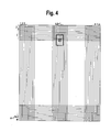
- eine schematische Darstellung eines Bildsensors einer Bilderfassungseinrichtung;
- Fig. 5
- eine Darstellung des Visierfensters bei der Positionierung nach
Fig. 3A ; - Fig. 6
- eine Darstellung des Visierfensters bei der Positionierung gemäß
Fig. 3B ; und - Fig. 7
- ein Flussdiagramm eines erfindungsgemäßen Verfahrens zum Ausrichten der in
Fig. 1 gezeigten Schusswaffe.
- Fig. 1
- a side view of a firearm according to the invention;
- Fig. 2
- the schematic structure of the target device according to the invention;
- Fig. 3A
- a first positioning of the target device for distance measurement according to the invention;
- Fig. 3B
- a second positioning of the target device according to the invention after elevation angle correction;
- Fig. 4
- a schematic representation of an image sensor of an image capture device;
- Fig. 5
- a representation of the visor window in positioning after
Fig. 3A ; - Fig. 6
- a representation of the visor window in the positioning according to
Fig. 3B ; and - Fig. 7
- a flow chart of a method according to the invention for aligning the in
Fig. 1 shown firearm.
In
Die Bauelemente der Schusswaffen-Zielvorrichtung 1 sind schematisch in
Die vorstehend aufgeführten Komponenten der Schusswaffen-Zielvorrichtung 1 sind - bis auf die Bildwiedergabeeinrichtung 18 - in einem Gehäuse 1' aufgenommen, welches am Rahmen der Schusswaffe 2 montiert werden kann. Die Ausrichtung der Entfernungsmesseinrichtung 12 ist dabei derart, dass die Achse 12' der Entfernungsmesseinrichtung 12 parallel zur Laufachse 22 verläuft. Die optische Achse 10' der Bilderfassungseinrichtung 10 ist hingegen so ausgerichtet, dass sie gegenüber der optischen Achse 12' der Entfernungsmesseinrichtung 12 und der Laufachse 22 nach unten geneigt ist, wie in
Die Bildwiedergabeeinrichtung 18 kann von einem auf das Gehäuse 1' aufsteckbaren oder an dem Gehäuse 1' anbringbaren Display, beispielsweise einem transflexiven Display, gebildet sein, oder die Bildwiedergabeeinrichtung 18 kann ein am Helm des Schützen angebrachtes Display sein, welches über Kabel oder drahtlos mit der Schusswaffen-Zielvorrichtung verbunden ist.The
Im gezeigtem Ausführungsbeispiel ist die Bilderfassungseinrichtung 10 von einer hochauflösenden Kamera mit zum Beispiel 4000 X 2250 Pixeln (= 9 Megapixel) gebildet. Zur optimalen Nutzung der Kameraauflösung wird die Bilderfassungseinrichtung 10 oder deren Sensor leicht nach unten geneigt eingebaut. Besitzt die Kamera zum Beispiel einen Öffnungswinkel von ± 20°, so wird sie mit einer Neigung von ca. 15° nach unten eingebaut.In the exemplary embodiment shown, the
In der Darstellung in
Das Visierfenster 3 wird dem Schützen in das von der Bilderfassungseinrichtung 10 aufgenommene und auf der Bildwiedergabeeinrichtung 18 wiedergegebene Bild der Zielobjekts Z eingeblendet. Das Visierfenster 3 kann dabei einen Teil des auf der Bildwiedergabeeinrichtung 18 dargestellten Bildes umrahmen oder kann dem gesamten Bildschirm der Bildwiedergabeeinrichtung 18 entsprechen.The
In der in
Gleichzeitig mit der Entfernungsmessung werden Position und Lage der Schusswaffen-Zielvorrichtung 1 mittels der Inertialmesseinheit 14 ermittelt.At the same time as the distance measurement, the position and position of the
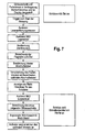
Der Ablauf des Zielvorgangs wird nachstehend unter Bezugnahme auf das Flussdiagramm in
Wie bereits in Verbindung mit
Da der Laser-Entfernungsmesser 12 kolinear, also parallel, zur Werferachse 22 montiert ist, wird mittels der Inertialmesseinheit 14 zugleich auch die Höhe des Ziels Z gegenüber der Position des Schützen bestimmt.Since the
Im Steuerungscomputer wird aus der ermittelten Entfernung zum Zielobjekt Z und der Höhenlage des Ziels Z gegenüber der Position des Schützen, also dem Ziel-Höhenwinkel und den in einem Speicher des Steuerungscomputers 16 abgespeicherten Waffen- und Geschossparametern der Schusswinkel, also der Elevationswinkel β berechnet, der erforderlich ist, um das Geschoss auf seiner ballistischen Bahn in das Ziel Z zu führen. Dieser Schusswinkel β ist in
Aufgrund dieser Berechnung wird der aus dem Sensor der Bilderfassungseinrichtung 10 ausgelesene Bildausschnitt um eine dem Schusswinkel β entsprechende Anzahl von Zeilen verschoben, wie in
Bei der eingangs genannten Sensorauflösung entspricht eine Pixelzeile einer Schusswinkeldifferenz von 0,01 °. Der in
In
In dem auf der Bildwiedergabeeinrichtung 18 dargestellten Bildausschnitt (Visierfenster 3 beziehungsweise 3') wird dem Schützen zudem über horizontale Pfeilsymbole 32 angezeigt, in welcher Azimut-Richtung er die Schusswaffe 2 seitlich schwenken muss, um das Fadenkreuz 30 in das in
Die visuelle Kontrolle und Nachführung des Azimuts (horizontale Nachführung) bietet zudem den Vorteil, unabhängig von Kreiseidriften oder Magnetfeldstörungen zu sein.The visual control and tracking of the azimuth (horizontal tracking) also has the advantage of being independent of circular drift or magnetic field interference.
Über vertikale Pfeilsymbole 34 wird dem Schützen angezeigt, ob er die Schusswaffe 2 steiler oder flacher halten soll. Des Weiteren wird ihm über gebogene oder kreisförmige Pfeildarstellungen 36 angezeigt, ob er die Rolllage der Schusswaffe 2 ändern muss, also die Schusswaffe 2 um die Laufachse beziehungsweise Werfachse 22 verdrehen muss.
Ist der optimale Schusswinkel β erreicht, wird dies dem Schützen durch ein optisches Signal auf dem Display der Bildwiedergabeeinrichtung 18 und/oder ein akustisches Signal mitgeteilt. Dieser optimale Schusswinkel ist dann erreicht, wenn sich das eingeblendete Fadenkreuz wieder an der gleichen Stelle auf dem Zielobjekt Z befindet wie in
Dieser Schusswinkel wird mittels der Inertialmesseinheit IMU 14 genau vermessen und der Schütze wird bei Erreichen des optimalen Schusswinkels durch eine Anzeige im Display der Bildwiedergabeeinrichtung 18, zum Beispiel durch ein grün leuchtendes Feld, darüber informiert, dass der optimale Schusswinkel erreicht worden ist. Der Schütze kann auf diese Weise stets kontrollieren, ob die auf der Grundlage der Zeilenverschiebung berechnete Fadenkreuzlage und die von der Inertialmesseinheit IMU 14 berechnete Schusswinkellage (grüne Leuchte im Display) übereinstimmende Daten liefern, sodass der Schütze ein redundantes System besitzt, was sicherheitstechnische Vorteile bietet.This shooting angle is measured accurately by means of the inertial measuring
Die Erfindung ist nicht auf das obige Ausführungsbeispiel beschränkt, das lediglich der allgemeinen Erläuterung des Kerngedankens der Erfindung dient. Im Rahmen des Schutzumfangs kann die erfindungsgemäße Vorrichtung vielmehr auch andere als die oben beschriebenen Ausgestaltungsformen annehmen. Die Vorrichtung kann hierbei insbesondere Merkmale aufweisen, die eine Kombination aus den jeweiligen Einzelmerkmalen der Ansprüche darstellen.The invention is not limited to the above embodiment, which merely serves to generally explain the essence of the invention. Within the scope of protection, the device according to the invention may also assume other than the above-described embodiments. In this case, the device may in particular have features that represent a combination of the respective individual features of the claims.
Bezugszeichen in den Ansprüchen, der Beschreibung und den Zeichnungen dienen lediglich dem besseren Verständnis der Erfindung und sollen den Schutzumfang nicht einschränken.Reference signs in the claims, the description and the drawings are only for the better understanding of the invention and are not intended to limit the scope.
Es bezeichnen:
- 1
- Schusswaffen-Zielvorrichtung
- 1'
- Gehäuse
- 2
- Schusswaffe
- 3
- Visierfenster (Bildausschnitt)
- 3'
- Visierfenster (Bildausschnitt)
- 10
- Bilderfassungseinrichtung
- 10'
- optische Achse
- 11
- Datenleitung
- 12
- Entfernungsmesseinrichtung
- 12'
Achse der Entfernungsmesseinrichtung 12- 13
- Datenleitung
- 14
- Inertialmesseinheit IMU
- 15
- Datenleitung
- 16
- Steuerungscomputer
- 17
- Datenleitung
- 18
- Bildwiedergabeeinrichtung
- 19
- Datenleitung
- 20
- Lauf
- 22
- Laufachse
- 24
- Abzugshebel
- 30
- Fadenkreuz
- 32
- horizontaler Pfeil
- 34
- vertikaler Pfeil
- 36
- gebogenen Pfeilsymbole
- P
- Verschiebungsrichtung
- V
- Visierlinie
- Z
- Zielobjekt
- 1
- Firearms aimer
- 1'
- casing
- 2
- firearm
- 3
- Visor window (picture detail)
- 3 '
- Visor window (picture detail)
- 10
- Image capture device
- 10 '
- optical axis
- 11
- data line
- 12
- Distance measuring device
- 12 '
- Axis of the
distance measuring device 12 - 13
- data line
- 14
- Inertial measuring unit IMU
- 15
- data line
- 16
- control computer
- 17
- data line
- 18
- Image reproduction device
- 19
- data line
- 20
- run
- 22
- Wheel shaft
- 24
- sear
- 30
- crosshairs
- 32
- horizontal arrow
- 34
- vertical arrow
- 36
- curved arrow symbols
- P
- shift direction
- V
- line of sight
- Z
- target
Claims (11)
dadurch gekennzeichnet,
characterized,
dadurch gekennzeichnet,
characterized,
wobei der Steuerungscomputer (16) so ausgebildet ist, dass er ein von der Bilderfassungseinrichtung (10) aufgenommenes Bild eines Zielobjekts (Z) derart auf der Bildwiedergabeeinrichtung (18) anzeigt, dass das Bild des Zielobjekts (Z) dann mit einer Visiermarkierung (30) in Überdeckung ist, wenn der Elevations-Winkel der Laufachse (22) dem Steigungswinkel der in Abhängigkeit von der Richtung zum Zielobjekt und der von der Entfernungsmesseinrichtung (12) ermittelten Entfernung zum Zielobjekt (Z) und unter Berücksichtigung von Waffen- und Geschossparametern vom Steuerungscomputer (16) berechneten Geschossflugbahn zum Zielobjekt (Z) entspricht.A firearm having a projectile barrel (20) and a sighting device (1) according to claim 1 or 2,
wherein the control computer (16) is arranged to display an image of a target object (Z) picked up by the image capture device (10) on the image display device (18) such that the image of the target object (Z) is then provided with a sighting mark (30). is coincidental when the elevation angle of the barrel axis (22) is the pitch angle of the distance to the target object (Z) determined in dependence on the direction to the target object and the distance measuring device (12) and taking into account weapon and projectile parameters ( 16) corresponds to the calculated projectile trajectory to the target object (Z).
dadurch gekennzeichnet,
dass die optische Achse (12') der Entfernungsmesseinrichtung (12) parallel zur Laufachse (22) verläuft.Firearm according to claim 3,
characterized,
in that the optical axis (12 ') of the distance measuring device (12) runs parallel to the running axis (22).
dadurch gekennzeichnet,
dass die optische Achse (10') der Bilderfassungseinrichtung (10) in Bezug auf die Laufachse (22) nach unten geneigt ist.Firearm according to claim 3 or 4,
characterized,
in that the optical axis (10 ') of the image capture device (10) is inclined downwards relative to the barrel axis (22).
gekennzeichnet durch die folgenden Schritte:
characterized by the following steps:
dadurch gekennzeichnet,
dass die Verlagerung der Überdeckung der Visiermarkierung (30) mit dem Bildausschnitt in Schritt f) derart erfolgt, dass der von der Bilderfassungseinrichtung (10) aufgenommene und auf der Bildwiedergabeeinrichtung (18) wiedergegebene Bildausschnitt verschoben wird.Method according to claim 6,
characterized,
that the displacement of the overlap of the sighting mark (30) with the image segment in step f) is carried out such that the (from the image acquisition device 10) recorded, and (on the image display device 18) reproduced image segment is moved.
dadurch gekennzeichnet,
dass die Verlagerung der Überdeckung der Visiermarkierung (30) mit dem Bildausschnitt in Schritt f) derart erfolgt, dass die auf der Bildwiedergabeeinrichtung (18) angezeigte Visiermarkierung (30) verschoben wird.Method according to claim 6 or 7,
characterized,
that the displacement of the overlap of the sighting mark (30) with the image segment in step f) is carried out such that the (on the image display device 18) sighting mark displayed (30) is moved.
dadurch gekennzeichnet,
dass vom Steuerungscomputer (16) in das auf der Bildwiedergabeeinrichtung (18) angezeigte Bild zumindest ein Richtungssymbol (32, 34) eingeblendet wird, das dem Schützen anzeigt, in welche Richtung er die Schusswaffe (2) bewegen muss, um das ursprünglich anvisierte Zielobjekt (Z) nach der im Schritt f) erfolgenden Verlagerung wieder mit der Visiermarkierung (30) in Überdeckung zu bringen.Method according to claim 6, 7 or 8,
characterized,
in that at least one directional symbol (32, 34) is displayed by the control computer (16) in the image displayed on the image display device (18), indicating to the shooter in which direction he has to move the firearm (2) in order to reach the target object originally targeted ( Z) to bring after the shift in step f) again with the sighting mark (30) in overlap.
dadurch gekennzeichnet,
dass vom Steuerungscomputer (16) in das auf der Bildwiedergabeeinrichtung (18) angezeigte Bild zumindest ein Symbol (36) eingeblendet wird, welches dem Schützen einen Hinweis darauf gibt, wie er die Schusswaffe (2) um die Laufachse (22) zu verdrehen hat, damit die berechnete Geschossflugbahn das anvisierte Zielobjekt (Z) trifft.Method according to one of claims 6 to 9,
characterized,
in that at least one symbol (36) is displayed by the control computer (16) in the image displayed on the image display device (18), which gives the shooter an indication of how he has to turn the firearm (2) about the barrel axis (22), so that the calculated projectile trajectory hits the targeted target (Z).
dadurch gekennzeichnet,
dass der Steuerungscomputer (16) in das auf der Bildwiedergabeeinrichtung (18) angezeigte Bild zumindest ein optisches Signal einblendet und/oder ein akustisches Signal abgibt, wenn die vom Steuerungscomputer (16) berechnete Geschossflugbahn das Zielobjekt (Z) trifft.Method according to one of claims 6 to 10,
characterized,
in that the control computer (16) inserts at least one optical signal into the image displayed on the image display device (18) and / or emits an acoustic signal when the projectile trajectory calculated by the control computer (16) hits the target object (Z).
Applications Claiming Priority (2)
| Application Number | Priority Date | Filing Date | Title |
|---|---|---|---|
| DE102011018947A DE102011018947A1 (en) | 2011-04-29 | 2011-04-29 | Firearm aiming device and firearm, and method for aligning a firearm |
| EP12002584.6A EP2518432B1 (en) | 2011-04-29 | 2012-04-12 | Firearm targeting device, firearm and method for aligning a firearm |
Related Parent Applications (3)
| Application Number | Title | Priority Date | Filing Date |
|---|---|---|---|
| EP12002584.6 Division | 2012-04-12 | ||
| EP12002584.6A Division EP2518432B1 (en) | 2011-04-29 | 2012-04-12 | Firearm targeting device, firearm and method for aligning a firearm |
| EP12002584.6A Division-Into EP2518432B1 (en) | 2011-04-29 | 2012-04-12 | Firearm targeting device, firearm and method for aligning a firearm |
Publications (2)
| Publication Number | Publication Date |
|---|---|
| EP2634523A1 true EP2634523A1 (en) | 2013-09-04 |
| EP2634523B1 EP2634523B1 (en) | 2019-09-11 |
Family
ID=45992023
Family Applications (2)
| Application Number | Title | Priority Date | Filing Date |
|---|---|---|---|
| EP13002726.1A Active EP2634523B1 (en) | 2011-04-29 | 2012-04-12 | Firearm targeting device, firearm and method for aligning a firearm |
| EP12002584.6A Active EP2518432B1 (en) | 2011-04-29 | 2012-04-12 | Firearm targeting device, firearm and method for aligning a firearm |
Family Applications After (1)
| Application Number | Title | Priority Date | Filing Date |
|---|---|---|---|
| EP12002584.6A Active EP2518432B1 (en) | 2011-04-29 | 2012-04-12 | Firearm targeting device, firearm and method for aligning a firearm |
Country Status (4)
| Country | Link |
|---|---|
| EP (2) | EP2634523B1 (en) |
| DE (1) | DE102011018947A1 (en) |
| ES (2) | ES2753184T3 (en) |
| PL (1) | PL2518432T3 (en) |
Families Citing this family (11)
| Publication number | Priority date | Publication date | Assignee | Title |
|---|---|---|---|---|
| US8833655B2 (en) | 2011-05-26 | 2014-09-16 | Burris Corporation | Magnification compensating sighting systems and methods |
| DE102011105303A1 (en) | 2011-06-22 | 2012-12-27 | Diehl Bgt Defence Gmbh & Co. Kg | fire control |
| TWI633272B (en) | 2012-02-04 | 2018-08-21 | 伯里斯公司 | Sighting system |
| US9250036B2 (en) | 2012-03-05 | 2016-02-02 | Burris Company, Inc. | Optical device utilizing ballistic zoom and methods for sighting a target |
| DE102013014619A1 (en) * | 2013-09-04 | 2015-03-05 | Rheinmetall Soldier Electronics Gmbh | Targeting means for handguns and small arms with the target agent as well as adjustment of the target agent |
| RU2674720C2 (en) * | 2014-02-07 | 2018-12-12 | Баррис Компани, Инк. | Optical device utilising ballistic zoom and method for sighting target (options) |
| FR3022337B1 (en) * | 2014-06-13 | 2018-08-03 | Gael Guillerm | METHODS AND SYSTEMS FOR ASSISTING A TARGET FOR A WEAPON, ESPECIALLY FOR DEFENSE LAUNCHER |
| US9423215B2 (en) | 2014-11-26 | 2016-08-23 | Burris Corporation | Multi-turn elevation knob for optical device |
| US10415934B2 (en) | 2015-02-27 | 2019-09-17 | Burris Company, Inc. | Self-aligning optical sight mount |
| CN111272014B (en) * | 2019-12-31 | 2022-05-31 | 北京晶品特装科技股份有限公司 | Fire control calculation control system and method based on dynamic scale |
| FR3120938B1 (en) * | 2021-03-22 | 2023-09-08 | Thales Sa | METHOD FOR ASSISTING SHOOTING AT A MOVING TARGET, ASSOCIATED DEVICE AND ASSEMBLY |
Citations (6)
| Publication number | Priority date | Publication date | Assignee | Title |
|---|---|---|---|---|
| US5456157A (en) * | 1992-12-02 | 1995-10-10 | Computing Devices Canada Ltd. | Weapon aiming system |
| EP0785406A2 (en) * | 1996-01-22 | 1997-07-23 | HE HOLDINGS, INC. dba HUGHES ELECTRONICS | Method and device for fire control of a high apogee trajectory weapon |
| US6499382B1 (en) * | 1998-08-24 | 2002-12-31 | General Dynamics Canada Ltd. | Aiming system for weapon capable of superelevation |
| US6873406B1 (en) * | 2002-01-11 | 2005-03-29 | Opti-Logic Corporation | Tilt-compensated laser rangefinder |
| US20050268521A1 (en) * | 2004-06-07 | 2005-12-08 | Raytheon Company | Electronic sight for firearm, and method of operating same |
| US20070137088A1 (en) * | 2005-11-01 | 2007-06-21 | Leupold & Stevens, Inc. | Ballistic ranging methods and systems for inclined shooting |
Family Cites Families (2)
| Publication number | Priority date | Publication date | Assignee | Title |
|---|---|---|---|---|
| ES2248442T3 (en) * | 2001-10-12 | 2006-03-16 | Oerlikon Contraves Ag | PROCEDURE AND INSTRUMENT TO POINT A GUN OF A GUN AND USE OF THE INSTRUMENT. |
| US20050241207A1 (en) * | 2004-03-10 | 2005-11-03 | Raytheon Company, A Corporation Of The State Of Delaware | Common aperture time-division-multiplexed laser rangefinder |
-
2011
- 2011-04-29 DE DE102011018947A patent/DE102011018947A1/en not_active Ceased
-
2012
- 2012-04-12 ES ES13002726T patent/ES2753184T3/en active Active
- 2012-04-12 EP EP13002726.1A patent/EP2634523B1/en active Active
- 2012-04-12 EP EP12002584.6A patent/EP2518432B1/en active Active
- 2012-04-12 PL PL12002584T patent/PL2518432T3/en unknown
- 2012-04-12 ES ES12002584.6T patent/ES2669544T3/en active Active
Patent Citations (6)
| Publication number | Priority date | Publication date | Assignee | Title |
|---|---|---|---|---|
| US5456157A (en) * | 1992-12-02 | 1995-10-10 | Computing Devices Canada Ltd. | Weapon aiming system |
| EP0785406A2 (en) * | 1996-01-22 | 1997-07-23 | HE HOLDINGS, INC. dba HUGHES ELECTRONICS | Method and device for fire control of a high apogee trajectory weapon |
| US6499382B1 (en) * | 1998-08-24 | 2002-12-31 | General Dynamics Canada Ltd. | Aiming system for weapon capable of superelevation |
| US6873406B1 (en) * | 2002-01-11 | 2005-03-29 | Opti-Logic Corporation | Tilt-compensated laser rangefinder |
| US20050268521A1 (en) * | 2004-06-07 | 2005-12-08 | Raytheon Company | Electronic sight for firearm, and method of operating same |
| US20070137088A1 (en) * | 2005-11-01 | 2007-06-21 | Leupold & Stevens, Inc. | Ballistic ranging methods and systems for inclined shooting |
Also Published As
| Publication number | Publication date |
|---|---|
| ES2669544T3 (en) | 2018-05-28 |
| EP2518432A1 (en) | 2012-10-31 |
| EP2634523B1 (en) | 2019-09-11 |
| DE102011018947A1 (en) | 2012-10-31 |
| PL2518432T3 (en) | 2018-09-28 |
| EP2518432B1 (en) | 2018-03-28 |
| ES2753184T3 (en) | 2020-04-07 |
Similar Documents
| Publication | Publication Date | Title |
|---|---|---|
| EP2634523B1 (en) | Firearm targeting device, firearm and method for aligning a firearm | |
| EP1859221B1 (en) | Sighting mechanism for fire arms | |
| EP1304539B1 (en) | Method and device for aiming a gun barrel and use of the device | |
| EP2878913B1 (en) | Fire control sight, handgun with such a fire control sigth and a method for aiming said handgun | |
| EP2275769B1 (en) | Fire control unit for a handgun | |
| DE102005007910A1 (en) | Firearm for long flight duration projectiles has fire guidance system with target data acquisition and adjusters for sight tube on weapon | |
| DE19719977C1 (en) | Video viewing-sight with integrated weapon control system for gun | |
| EP1314949B1 (en) | Method and device for assessing the aiming errors of a weapon system and use of the device | |
| KR20120064429A (en) | Firearm system and method for contolling a firearm unit | |
| EP3150956A1 (en) | Fire guide device for a handgun and a handgun | |
| EP1314950B1 (en) | Method and device for assessing the aiming errors of a weapon system and use of the device | |
| DE102014019200A1 (en) | automatic weapon | |
| EP3034983B1 (en) | Automatic gun | |
| DE102008015423A1 (en) | Visor with objective viewpoint e.g. for weapons with ammunition for flight paths, involves having sight line straightening at target against running axis by vertical or horizontal tilting | |
| DE1951622A1 (en) | Arrangement for simulating firing paths | |
| DE4111935C2 (en) | ||
| EP3350536B1 (en) | Remotely controllable weapon station and method for operating a controllable weapon station | |
| DE318160C (en) | ||
| DE102005021044A1 (en) | Device has target unit with which camera is combined, which can steadily record images, which can be viewed by the target unit whereby device consists of firearm at which adjustable target unit can be fixed | |
| DE102011107950A1 (en) | System of e.g. firearms, to prevent e.g. civilian aircraft collision with e.g. civilian building, has communication apparatus from which output signal generated by applying logic function to transmission information is sent to weapons | |
| DE19806911C2 (en) | Procedure for monitoring the alignment of an artillery weapon | |
| DE1266179B (en) | System for the training of direction and steering guards | |
| DE19935816C2 (en) | Automatic system for the calibration of target devices (telescopes) on rifles using a laser beam and servomotors | |
| WO2023042195A1 (en) | Smart aiming device with built-in training system for marksmanship and firearm operation | |
| RU2436029C1 (en) | Sighting method |
Legal Events
| Date | Code | Title | Description |
|---|---|---|---|
| PUAI | Public reference made under article 153(3) epc to a published international application that has entered the european phase |
Free format text: ORIGINAL CODE: 0009012 |
|
| AC | Divisional application: reference to earlier application |
Ref document number: 2518432 Country of ref document: EP Kind code of ref document: P |
|
| AK | Designated contracting states |
Kind code of ref document: A1 Designated state(s): AL AT BE BG CH CY CZ DE DK EE ES FI FR GB GR HR HU IE IS IT LI LT LU LV MC MK MT NL NO PL PT RO RS SE SI SK SM TR |
|
| AX | Request for extension of the european patent |
Extension state: BA ME |
|
| 17P | Request for examination filed |
Effective date: 20140211 |
|
| STAA | Information on the status of an ep patent application or granted ep patent |
Free format text: STATUS: EXAMINATION IS IN PROGRESS |
|
| 17Q | First examination report despatched |
Effective date: 20170712 |
|
| GRAP | Despatch of communication of intention to grant a patent |
Free format text: ORIGINAL CODE: EPIDOSNIGR1 |
|
| STAA | Information on the status of an ep patent application or granted ep patent |
Free format text: STATUS: GRANT OF PATENT IS INTENDED |
|
| INTG | Intention to grant announced |
Effective date: 20190403 |
|
| RIN1 | Information on inventor provided before grant (corrected) |
Inventor name: NEWZELLA, ALFONS |
|
| GRAS | Grant fee paid |
Free format text: ORIGINAL CODE: EPIDOSNIGR3 |
|
| GRAA | (expected) grant |
Free format text: ORIGINAL CODE: 0009210 |
|
| STAA | Information on the status of an ep patent application or granted ep patent |
Free format text: STATUS: THE PATENT HAS BEEN GRANTED |
|
| AC | Divisional application: reference to earlier application |
Ref document number: 2518432 Country of ref document: EP Kind code of ref document: P |
|
| AK | Designated contracting states |
Kind code of ref document: B1 Designated state(s): AL AT BE BG CH CY CZ DE DK EE ES FI FR GB GR HR HU IE IS IT LI LT LU LV MC MK MT NL NO PL PT RO RS SE SI SK SM TR |
|
| REG | Reference to a national code |
Ref country code: GB Ref legal event code: FG4D Free format text: NOT ENGLISH |
|
| REG | Reference to a national code |
Ref country code: CH Ref legal event code: EP |
|
| REG | Reference to a national code |
Ref country code: AT Ref legal event code: REF Ref document number: 1178992 Country of ref document: AT Kind code of ref document: T Effective date: 20190915 |
|
| REG | Reference to a national code |
Ref country code: DE Ref legal event code: R096 Ref document number: 502012015294 Country of ref document: DE Ref country code: IE Ref legal event code: FG4D Free format text: LANGUAGE OF EP DOCUMENT: GERMAN |
|
| REG | Reference to a national code |
Ref country code: NL Ref legal event code: MP Effective date: 20190911 |
|
| REG | Reference to a national code |
Ref country code: LT Ref legal event code: MG4D |
|
| PG25 | Lapsed in a contracting state [announced via postgrant information from national office to epo] |
Ref country code: NO Free format text: LAPSE BECAUSE OF FAILURE TO SUBMIT A TRANSLATION OF THE DESCRIPTION OR TO PAY THE FEE WITHIN THE PRESCRIBED TIME-LIMIT Effective date: 20191211 Ref country code: BG Free format text: LAPSE BECAUSE OF FAILURE TO SUBMIT A TRANSLATION OF THE DESCRIPTION OR TO PAY THE FEE WITHIN THE PRESCRIBED TIME-LIMIT Effective date: 20191211 Ref country code: FI Free format text: LAPSE BECAUSE OF FAILURE TO SUBMIT A TRANSLATION OF THE DESCRIPTION OR TO PAY THE FEE WITHIN THE PRESCRIBED TIME-LIMIT Effective date: 20190911 Ref country code: LT Free format text: LAPSE BECAUSE OF FAILURE TO SUBMIT A TRANSLATION OF THE DESCRIPTION OR TO PAY THE FEE WITHIN THE PRESCRIBED TIME-LIMIT Effective date: 20190911 Ref country code: HR Free format text: LAPSE BECAUSE OF FAILURE TO SUBMIT A TRANSLATION OF THE DESCRIPTION OR TO PAY THE FEE WITHIN THE PRESCRIBED TIME-LIMIT Effective date: 20190911 Ref country code: SE Free format text: LAPSE BECAUSE OF FAILURE TO SUBMIT A TRANSLATION OF THE DESCRIPTION OR TO PAY THE FEE WITHIN THE PRESCRIBED TIME-LIMIT Effective date: 20190911 |
|
| PG25 | Lapsed in a contracting state [announced via postgrant information from national office to epo] |
Ref country code: LV Free format text: LAPSE BECAUSE OF FAILURE TO SUBMIT A TRANSLATION OF THE DESCRIPTION OR TO PAY THE FEE WITHIN THE PRESCRIBED TIME-LIMIT Effective date: 20190911 Ref country code: AL Free format text: LAPSE BECAUSE OF FAILURE TO SUBMIT A TRANSLATION OF THE DESCRIPTION OR TO PAY THE FEE WITHIN THE PRESCRIBED TIME-LIMIT Effective date: 20190911 Ref country code: RS Free format text: LAPSE BECAUSE OF FAILURE TO SUBMIT A TRANSLATION OF THE DESCRIPTION OR TO PAY THE FEE WITHIN THE PRESCRIBED TIME-LIMIT Effective date: 20190911 Ref country code: GR Free format text: LAPSE BECAUSE OF FAILURE TO SUBMIT A TRANSLATION OF THE DESCRIPTION OR TO PAY THE FEE WITHIN THE PRESCRIBED TIME-LIMIT Effective date: 20191212 |
|
| REG | Reference to a national code |
Ref country code: ES Ref legal event code: FG2A Ref document number: 2753184 Country of ref document: ES Kind code of ref document: T3 Effective date: 20200407 |
|
| PG25 | Lapsed in a contracting state [announced via postgrant information from national office to epo] |
Ref country code: PT Free format text: LAPSE BECAUSE OF FAILURE TO SUBMIT A TRANSLATION OF THE DESCRIPTION OR TO PAY THE FEE WITHIN THE PRESCRIBED TIME-LIMIT Effective date: 20200113 Ref country code: EE Free format text: LAPSE BECAUSE OF FAILURE TO SUBMIT A TRANSLATION OF THE DESCRIPTION OR TO PAY THE FEE WITHIN THE PRESCRIBED TIME-LIMIT Effective date: 20190911 Ref country code: PL Free format text: LAPSE BECAUSE OF FAILURE TO SUBMIT A TRANSLATION OF THE DESCRIPTION OR TO PAY THE FEE WITHIN THE PRESCRIBED TIME-LIMIT Effective date: 20190911 Ref country code: RO Free format text: LAPSE BECAUSE OF FAILURE TO SUBMIT A TRANSLATION OF THE DESCRIPTION OR TO PAY THE FEE WITHIN THE PRESCRIBED TIME-LIMIT Effective date: 20190911 Ref country code: NL Free format text: LAPSE BECAUSE OF FAILURE TO SUBMIT A TRANSLATION OF THE DESCRIPTION OR TO PAY THE FEE WITHIN THE PRESCRIBED TIME-LIMIT Effective date: 20190911 |
|
| PG25 | Lapsed in a contracting state [announced via postgrant information from national office to epo] |
Ref country code: IS Free format text: LAPSE BECAUSE OF FAILURE TO SUBMIT A TRANSLATION OF THE DESCRIPTION OR TO PAY THE FEE WITHIN THE PRESCRIBED TIME-LIMIT Effective date: 20200224 Ref country code: CZ Free format text: LAPSE BECAUSE OF FAILURE TO SUBMIT A TRANSLATION OF THE DESCRIPTION OR TO PAY THE FEE WITHIN THE PRESCRIBED TIME-LIMIT Effective date: 20190911 Ref country code: SK Free format text: LAPSE BECAUSE OF FAILURE TO SUBMIT A TRANSLATION OF THE DESCRIPTION OR TO PAY THE FEE WITHIN THE PRESCRIBED TIME-LIMIT Effective date: 20190911 Ref country code: SM Free format text: LAPSE BECAUSE OF FAILURE TO SUBMIT A TRANSLATION OF THE DESCRIPTION OR TO PAY THE FEE WITHIN THE PRESCRIBED TIME-LIMIT Effective date: 20190911 |
|
| REG | Reference to a national code |
Ref country code: DE Ref legal event code: R097 Ref document number: 502012015294 Country of ref document: DE |
|
| PLBE | No opposition filed within time limit |
Free format text: ORIGINAL CODE: 0009261 |
|
| STAA | Information on the status of an ep patent application or granted ep patent |
Free format text: STATUS: NO OPPOSITION FILED WITHIN TIME LIMIT |
|
| PG2D | Information on lapse in contracting state deleted |
Ref country code: IS |
|
| PG25 | Lapsed in a contracting state [announced via postgrant information from national office to epo] |
Ref country code: DK Free format text: LAPSE BECAUSE OF FAILURE TO SUBMIT A TRANSLATION OF THE DESCRIPTION OR TO PAY THE FEE WITHIN THE PRESCRIBED TIME-LIMIT Effective date: 20190911 Ref country code: IS Free format text: LAPSE BECAUSE OF FAILURE TO SUBMIT A TRANSLATION OF THE DESCRIPTION OR TO PAY THE FEE WITHIN THE PRESCRIBED TIME-LIMIT Effective date: 20200112 |
|
| 26N | No opposition filed |
Effective date: 20200615 |
|
| PG25 | Lapsed in a contracting state [announced via postgrant information from national office to epo] |
Ref country code: SI Free format text: LAPSE BECAUSE OF FAILURE TO SUBMIT A TRANSLATION OF THE DESCRIPTION OR TO PAY THE FEE WITHIN THE PRESCRIBED TIME-LIMIT Effective date: 20190911 |
|
| PG25 | Lapsed in a contracting state [announced via postgrant information from national office to epo] |
Ref country code: MC Free format text: LAPSE BECAUSE OF FAILURE TO SUBMIT A TRANSLATION OF THE DESCRIPTION OR TO PAY THE FEE WITHIN THE PRESCRIBED TIME-LIMIT Effective date: 20190911 |
|
| REG | Reference to a national code |
Ref country code: CH Ref legal event code: PL |
|
| PG25 | Lapsed in a contracting state [announced via postgrant information from national office to epo] |
Ref country code: LU Free format text: LAPSE BECAUSE OF NON-PAYMENT OF DUE FEES Effective date: 20200412 Ref country code: LI Free format text: LAPSE BECAUSE OF NON-PAYMENT OF DUE FEES Effective date: 20200430 Ref country code: CH Free format text: LAPSE BECAUSE OF NON-PAYMENT OF DUE FEES Effective date: 20200430 |
|
| REG | Reference to a national code |
Ref country code: BE Ref legal event code: MM Effective date: 20200430 |
|
| PG25 | Lapsed in a contracting state [announced via postgrant information from national office to epo] |
Ref country code: BE Free format text: LAPSE BECAUSE OF NON-PAYMENT OF DUE FEES Effective date: 20200430 |
|
| PG25 | Lapsed in a contracting state [announced via postgrant information from national office to epo] |
Ref country code: IE Free format text: LAPSE BECAUSE OF NON-PAYMENT OF DUE FEES Effective date: 20200412 |
|
| REG | Reference to a national code |
Ref country code: AT Ref legal event code: MM01 Ref document number: 1178992 Country of ref document: AT Kind code of ref document: T Effective date: 20200412 |
|
| PG25 | Lapsed in a contracting state [announced via postgrant information from national office to epo] |
Ref country code: AT Free format text: LAPSE BECAUSE OF NON-PAYMENT OF DUE FEES Effective date: 20200412 |
|
| PG25 | Lapsed in a contracting state [announced via postgrant information from national office to epo] |
Ref country code: TR Free format text: LAPSE BECAUSE OF FAILURE TO SUBMIT A TRANSLATION OF THE DESCRIPTION OR TO PAY THE FEE WITHIN THE PRESCRIBED TIME-LIMIT Effective date: 20190911 Ref country code: MT Free format text: LAPSE BECAUSE OF FAILURE TO SUBMIT A TRANSLATION OF THE DESCRIPTION OR TO PAY THE FEE WITHIN THE PRESCRIBED TIME-LIMIT Effective date: 20190911 Ref country code: CY Free format text: LAPSE BECAUSE OF FAILURE TO SUBMIT A TRANSLATION OF THE DESCRIPTION OR TO PAY THE FEE WITHIN THE PRESCRIBED TIME-LIMIT Effective date: 20190911 |
|
| PG25 | Lapsed in a contracting state [announced via postgrant information from national office to epo] |
Ref country code: MK Free format text: LAPSE BECAUSE OF FAILURE TO SUBMIT A TRANSLATION OF THE DESCRIPTION OR TO PAY THE FEE WITHIN THE PRESCRIBED TIME-LIMIT Effective date: 20190911 |
|
| P01 | Opt-out of the competence of the unified patent court (upc) registered |
Effective date: 20230509 |
|
| PGFP | Annual fee paid to national office [announced via postgrant information from national office to epo] |
Ref country code: IT Payment date: 20230426 Year of fee payment: 12 Ref country code: FR Payment date: 20230420 Year of fee payment: 12 Ref country code: ES Payment date: 20230627 Year of fee payment: 12 Ref country code: DE Payment date: 20230427 Year of fee payment: 12 |
|
| PGFP | Annual fee paid to national office [announced via postgrant information from national office to epo] |
Ref country code: GB Payment date: 20230419 Year of fee payment: 12 |