EP0785406A2 - Method and device for fire control of a high apogee trajectory weapon - Google Patents
Method and device for fire control of a high apogee trajectory weapon Download PDFInfo
- Publication number
- EP0785406A2 EP0785406A2 EP97300357A EP97300357A EP0785406A2 EP 0785406 A2 EP0785406 A2 EP 0785406A2 EP 97300357 A EP97300357 A EP 97300357A EP 97300357 A EP97300357 A EP 97300357A EP 0785406 A2 EP0785406 A2 EP 0785406A2
- Authority
- EP
- European Patent Office
- Prior art keywords
- target
- weapon
- video display
- microprocessor
- range finder
- Prior art date
- Legal status (The legal status is an assumption and is not a legal conclusion. Google has not performed a legal analysis and makes no representation as to the accuracy of the status listed.)
- Granted
Links
Images
Classifications
-
- F—MECHANICAL ENGINEERING; LIGHTING; HEATING; WEAPONS; BLASTING
- F41—WEAPONS
- F41G—WEAPON SIGHTS; AIMING
- F41G1/00—Sighting devices
- F41G1/46—Sighting devices for particular applications
- F41G1/48—Sighting devices for particular applications for firing grenades from rifles
-
- F—MECHANICAL ENGINEERING; LIGHTING; HEATING; WEAPONS; BLASTING
- F41—WEAPONS
- F41G—WEAPON SIGHTS; AIMING
- F41G3/00—Aiming or laying means
- F41G3/06—Aiming or laying means with rangefinder
-
- F—MECHANICAL ENGINEERING; LIGHTING; HEATING; WEAPONS; BLASTING
- F41—WEAPONS
- F41G—WEAPON SIGHTS; AIMING
- F41G3/00—Aiming or laying means
- F41G3/14—Indirect aiming means
-
- F—MECHANICAL ENGINEERING; LIGHTING; HEATING; WEAPONS; BLASTING
- F41—WEAPONS
- F41G—WEAPON SIGHTS; AIMING
- F41G3/00—Aiming or laying means
- F41G3/14—Indirect aiming means
- F41G3/16—Sighting devices adapted for indirect laying of fire
- F41G3/165—Sighting devices adapted for indirect laying of fire using a TV-monitor
Definitions
- LW Land Warrior
- the LW system may be "worn” by a soldier during day-to-day military operations. It includes: improvements in communications, including three separate radios carried by the user; an "on-board" microprocessor for battle operations, navigation, and messaging; night vision equipment, including infrared and thermal weapon sighting; improved weaponry, including computer enhanced fire control; ballistic protection, including advanced body armor; and, load carrying capability, including a fully adjustable modular pack system.
- features such as these provide the individual soldier with enhanced lethality, command and control, survivability, mobility, and sustainment.
Landscapes
- Engineering & Computer Science (AREA)
- General Engineering & Computer Science (AREA)
- Physics & Mathematics (AREA)
- Optics & Photonics (AREA)
- Aiming, Guidance, Guns With A Light Source, Armor, Camouflage, And Targets (AREA)
- Input Circuits Of Receivers And Coupling Of Receivers And Audio Equipment (AREA)
- Electrical Discharge Machining, Electrochemical Machining, And Combined Machining (AREA)
- Control Of Electric Motors In General (AREA)
Abstract
Description
- The present invention relates generally to a method of fire control for a weapon requiring a high apogee trajectory for successfully engaging a target with an ordnance round. More specifically, the present invention relates to a device and an improved method of computer controlled firing of a grenade launcher which may used as one component of a larger comprehensive warfare system.
- Modern technology, especially computers and electronics, have advanced rapidly in the recent past. It is only logical that these technological advances would be applied to the art of war, specifically to weapons and other equipment designed to make the modern soldier a more efficient fighting machine.
- In pursuit of a more efficient fighting machine, a fully integrated, multi-functional, soldier-centered, computer enhanced, warfare system, aka the "Land Warrior" system ("LW"), has been developed. The LW system may be "worn" by a soldier during day-to-day military operations. It includes: improvements in communications, including three separate radios carried by the user; an "on-board" microprocessor for battle operations, navigation, and messaging; night vision equipment, including infrared and thermal weapon sighting; improved weaponry, including computer enhanced fire control; ballistic protection, including advanced body armor; and, load carrying capability, including a fully adjustable modular pack system. Features such as these provide the individual soldier with enhanced lethality, command and control, survivability, mobility, and sustainment.
- Such an LW system is typically broken up into various subsystems, each subsystem consisting of similar or related hardware which is dedicated to accomplishing a certain task or family of tasks. The LW system is composed of five such subsystems: (1) Computer/Radio Subsystem ("CRS"); (2) Weapon Subsystem ("WS"); (3) Integrated Helmet Assembly Subsystem ("IHAS"); (4) Protective Clothing and Individual Equipment Subsystem ("PCIES"); and, (5) LW Software Subsystem ("SS").
- With regard to weapons in general, the M16 (also known as the Colt AR-15, from Colt Industries) is the standard weapon issued to virtually all U.S. Army combat personnel. It is a lightweight, durable rifle capable of firing 5.56 millimeter rounds in the semi-automatic or fully automatic mode. The M16 makes up the core of the LW Weapon Subsystem. In order to increase the flexibility and firepower of the M16, a grenade launcher may be attached. The standard U.S. Army issue grenade launcher (designated by the military as the M203) is mounted directly under the barrel of the M16 and is usually carried by several members of a military contingent. The grenade launcher provides a variety of long range attack options (using various types of grenades) combined with the mobility of a portable weapon.
- In the past, aiming a grenade launcher has not been a study in precision ballistics. An ordnance round such as a shoulder-fired grenade usually needs a very high apogee trajectory to reach a distant target. The firing angle required to accomplish this high apogee trajectory is known as a superelevation angle. Normally, the M203 employs an iron sight for aiming. The grenadier must estimate the range to the target and then set the sight for the proper range. A first grenade is launched and the impact is observed by the grenadier or other personnel. The sight is then manually adjusted based on the location of the impact of the first grenade and a second grenade is fired. This process, known in artillery jargon as "walking in" rounds, is repeated until the target is successfully engaged.
- The disadvantages of "walking in" rounds to successfully engage a target are obvious. First, crucial time may be lost which could result in the disruption of precisely timed battle plans. Furthermore, the target may have time to move or return fire before it is eliminated, thus creating unnecessary risk for the grenadier and his comrades. Second, valuable ammunition is wasted merely determining the accurate range of the target.
- In the recent past, improvements in laser technology have improved the way in which weapons are used. First, laser range finders are used to accurately determine the distance from a shooter to a target by reflecting a laser pulse off the target. It can be seen, then, that for weapons needing an accurate range to successfully engage a target, laser technology can improve the overall efficiency of a weapon. Second, laser sights enable a shooter to eliminate the error involved when a human eye is required to look some distance through several pieces of metal (the sight) to aim a short range weapon, such as a handgun. By providing a pinpoint, error-free aim point, laser technology can also improve the overall efficiency of a short range weapon.
- Currently, there is no commercially available device known which uses laser technology to improve the efficiency of weapons requiring a high apogee trajectory, such as a grenade launcher, to successfully engage a target. Even if a grenadier used a precision range finding device such as a laser range finder, there would still be a large potential for human error. First, the grenadier would need to determine the firing angle of the grenade launcher and then maintain the angle while firing the grenade. Furthermore, the grenadier would need to sight through the fixed iron sight to maintain the proper azimuth to engage the target. To achieve both of these tasks while firing from a relatively unstable position, i.e., the shoulder, would be difficult at best.
- The device and improved method of fire control for a grenade launcher of the present invention overcomes the problems experienced in the past when the standard iron sight of the grenade launcher was used, regardless of the method used to determine the range of the target. The method and device of the present invention utilize precise laser range finding techniques in combination with an advanced digital compass assembly and a microprocessor which together provide a substantial likelihood that the grenadier will successfully engage the target on the first shot. By eliminating the old method of walking in rounds, crucial time and valuable ammunition are conserved, thus improving the overall efficiency of the soldier.
- The present method and device utilizes hardware from the Weapon Subsystem ("WS"), the Computer/Radio Subsystem ("CRS") and the Integrated Helmet Assembly Subsystem ("IHAS") of the above-described Land Warrior system, as well as the Software Subsystem ("SS"), as further described herein. The WS provides the means of delivery (i.e., the M203 grenade launcher, typically mounted on an M16 rifle), and the aiming mechanism (the laser range finder/digital compass assembly). The CRS provides the computational ability necessary to calculate a ballistic solution given the range and proper azimuth of the target. The IHAS provides a video display which allows the grenadier to physically aim the grenade launcher and take advantage of the computer controlled fire control. Finally, the SS provides the means by which all other subsystems communicate with each other and also provides the mathematical capability to calculate a correct superelevation angle based on a given range of a target.
- The actual method of fire control for the grenade launcher is as follows. The grenadier locates a target and actuates a laser range finder/digital compass assembly ("LRF/DCA") which is mounted on the M16/M203 combination. The LRF/DCA determines the range and proper azimuth of the target and provides them to a microprocessor (of the CRS) carried by the user. Using a preprogrammed look-up table, the microprocessor calculates a ballistic solution. That is, the microprocessor calculates the proper superelevation angle needed for the grenade to successfully engage the target and then displays it on an LED display of the LRF/DCA or on a video display of the IHAS. The grenadier uses the vertical angle measurement capability of the DCA to monitor the angle of the weapon as the weapon is lifted by the grenadier. When the display of the LRF/DCA indicates that the proper superelevation angle has been achieved, the grenadier maintains the weapon at the proper firing angle. After ensuring that the proper azimuth has been maintained, the grenadier may then fire the grenade launcher with the substantial likelihood that the target will be successfully engaged on the first shot.
- The invention itself, together with further objects and attendant advantages, will be best understood by reference to the following detailed description, taken in conjunction with the accompanying drawings.
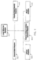
- Figure 1 is a block diagram of a warfare system which incorporates the method and the device of the present invention.
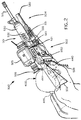
- Figure 2 is a elevational side view of the Weapon Subsystem and associated hardware used in the method and device of the present invention.
- The overall structure of the warfare system which incorporates the method and device of the present invention is shown in Figure 1. The
LW system 100 includes five separate subsystems: the Computer/Radio Subsystem ("CRS") 200; the Software Subsystem ("SS") 300; the Integrated Helmet Assembly Subsystem ("IHAS") 400; the Weapon Subsystem ("WS") 500; and, the Personal Clothing and Individual Equipment Subsystem ("PCIES") 600. - The method and device of the present invention primarily utilizes the hardware of the WS 500, best shown in Figure 2. A standard, military issue M16
rifle 501 having astock 502, acentral section 503, and aforward section 504, forms the core of the WS 500. AnM203 grenade launcher 520, also standard military issue, is mounted on theforward section 504 of therifle 501 underhand guards 510 andbarrel 515. - The LRF/
DCA 530 is also mounted, using clamps (not shown), on theforward section 504 of therifle 501, but to one side of hand guards 510. The laser range finder portion of the LRF/DCA 530 is a modified version of a commercially available mini-laser range finder developed by Fibertek for Night Vision Electronic Sensors Directorate. For the preferred embodiment of the present invention, the Fibertek packaging has been redesigned to improve the shock resistance of the LRF and to facilitate manufacturing. The laser is a flashlamp pumped Optical Parameter Oscillator ("OPO") shifted Yttrium Aluminum Garnet ("YAG") laser and is used to generate an eye safe, 5 nanosecond pulse having a wavelength of 1.57 micrometers. The laser pulse is transmitted through an integrated telescope (not shown), is reflected off a target (not shown), and is detected by an avalanche photodiode ("APD") to accurately determine the range of a target ±1 meter. As an added safety measure, a silicon filter blocks all non-eye safe wavelengths but passes the 1.57 micrometer wavelength (the laser actually emits a beam of light 1.06 micrometers in wavelength which is not eye safe at the power levels needed to meet the LW system requirements; the 1.06 micrometer wavelength light is converted to 1.57 micrometers and the unconverted light is blocked by the above-mentioned filter). An integral spotting light (not shown) provides a means for zeroing the invisible LRF beam to the bore of therifle 501. - Integrated within the LRF/
DCA 530 is the Digital Compass Assembly ("DCA"), not shown. The DCA is a commercially available MELIOS C/VAM supplied by Leica which is modified in accordance with the present invention. To achieve the vertical angle and azimuth accuracy needed, the calibration procedure is revised and the tilt sensors are slightly enlarged to respond up to the required ± 45 degrees angle variation instead of the standard ± 35 degrees angle variation (high apogee trajectory weapons achieve maximum distance when the firing angle is 45 degrees). Three solid-state magneto-resistive sensors are used to accurately transduce the earth's magnetic field in all battlefield environments. The DCA has an onboard microprocessor which translates the magneto-resistive sensor signals into azimuth and vertical angle readings. - A low power, high
reliability LED display 533 is supplied as part of the LRF/DCA 530. TheLED display 533 provides visual indicators which show mode status, alphanumeric readouts of range, azimuth, and vertical angle. Thedisplay 533 may contain a variable brightness control with an off position to maintain light security. Thedisplay 533 interfaces with and is controlled by the LRF/DCA microprocessor without additional support electronics. - The LRF/
DCA 530 has two sets of controls. The set-upcontrols 531, which are simple membrane switches of conventional construction, are located on the outside of the LRF/DCA housing, slightly lower than a horizontal plane which extends through the longitudinal centerline of the LRF/DCA 530, best shown in Figure 2. Functions of the set-upcontrols 531 may include turning the unit on and off, setting the operating mode, controlling video display, and providing backup for the remote CRS controls 550. The operations controls 532 are located above the set-upcontrols 531 on the housing of the LRF/DCA 530, also shown in Figure 2. Functions of the operations controls 532 may include firing the laser, turning on a spotting light (not shown), selecting the M203 mode, and providing backup for the remote CRS controls 550 further described herein. - Another video display 440 which the grenadier can use to take advantage of the computer controlled fire control is the Sensor Display Assembly (not shown) of the
IHAS 400. The specific configuration of the display is different for day and night missions. A standard helmet mount 441 allows either a day 440 or night component (not shown) to be attached. The attachment is similar to a standard night vision goggle mount (not shown) and allows adjustments of the display 440 in up/down, right/left, fore/aft, and tilt motions. The Night Sensor/Display Component ("NSDC") (not shown) is worn as a monocular night vision goggle which is positioned over the chosen eye. The day component 440 is also monocular, but can be placed in a variety of positions: a "look-under" mode (where the grenadier can see the display 440 but can also look under it); a see-through display mode (where the grenadier looks at a partially transparent display, allowing vision through the display 440); or a fully occluded mode (where the grenadier looks at the display 440 only and cannot see under or through the display 440). - The remote CRS controls 550 are mounted on the side of the
central section 503 of therifle 501 and are electrically connected to the microprocessor of theCRS 200. The remote CRS controls 550 allow the user to select the video display (440 or 533) where the video information will appear. The electronics (power and control) of theWS 500 are wired to theCRS 200 viaexternal cable 599. - The method of fire control for the
M203 grenade launcher 520 is as follows. It is assumed that the grenadier is at the ready, the LRF/DCA 530 has been activated using set-upcontrols 531, and a grenade is loaded into thelauncher 520. The grenadier locates a target and selects the M203 mode by depressing the proper button on the operations controls 532. The grenadier points the LRF/DCA 530 at the target and then "fires" the laser beam of the LRF/DCA 520, also controlled by the operations controls 532. The LRF/DCA 530 determines the range and provides it either to the microprocessor (not shown) of theCRS 200 or to the microprocessor of the LRF/DCA 530. Using a pre-programmed look-up table, one of the microprocessors calculates a ballistic solution. That is, the microprocessor (not shown) calculates the proper superelevation angle needed for the grenade to successfully engage the target and then displays it on the selected video display: either on theLED display 533 of the LRF/DCA 530 or on the day component 440 of the Sensor Display Assembly (during the day) or on the night component NSDC (not shown) located on theIHAS 400. The proper superelevation angle appears as a negative angle on the selectedvideo display 440 or 533. As the LRF/DCA 530 determines the range of the target, the azimuth is set to zero and is also displayed on the selected video display. For example, if the proper superelevation angle for target engagement was 45 degrees above horizontal, then the information appearing on the selected video display would be "AZ: 0000m" and "MILS VERT: -45m". As the grenadier raises the muzzle of the weapon, the tilt sensors (not shown) of the LRF/DCA 530 allow the angle of thegrenade launcher 520 to be monitored: the selectedvideo display 440 or 533 reflects the gradually changing angle from -45 degrees to 0 degrees. When the display reads 0 degrees superelevation and the proper azimuth of 0 degrees, the weapon is on target (any straying off the correct azimuth would be indicated on the selected display by some angle other than 0 degrees; to regain a proper fix on the target, the grenadier would merely swing thegrenade launcher 520 in a direction so that the azimuth reading would return to zero). Thegrenade launcher 520 is then fired usingtrigger 521. - The method of fire control of the present invention is not limited to the M16 mounted
M203 grenade launcher 520. It can also be used with any number of high apogee trajectory weapons, including the MK19 grenade machine gun and the like. - Of course, it should be understood that a wide range of changes and modifications can be made to the preferred embodiment described above. It is therefore intended that the foregoing detailed description be regarded as illustrative rather than limiting and that it be understood that it is the following claims, including all equivalents, which are intended to define the scope of the invention.
Claims (10)
- A device for delivering an ordnance round to a target, said device comprising:a weapon (520);a laser range finder/digital compass assembly (530), said laser range finder/digital compass assembly (530) being mounted to said weapon (520), said laser range finder/digital compass assembly (530) having a laser range finder portion and a digital compass portion;a first microprocessor, said first microprocessor being in electrical communication with said laser range finder/digital compass assembly (530); and,a first video display (533), said first video display being in electrical communication with said laser range finder/digital compass assembly (530), said first video display (533) further being in electrical communication with said first microprocessor.
- The device according to Claim 1 wherein said weapon (520) comprises a high apogee trajectory weapon.
- The device according to Claim 1 wherein said weapon (520) comprises a portable grenade launcher.
- The device according to Claim 1 wherein said laser range finder portion and said digital compass portion are integrated within a single housing.
- The device according to Claim 4 wherein said first video display (533) is integrated within said single housing.
- The device according to Claim 4 further comprising a second microprocessor, said second microprocessor being integrated within said single housing, said second microprocessor being in electrical communication with said laser range finder/digital compass assembly (530).
- The device according to Claim 1 further comprising a second video display (440), said second video display (440) being in electrical communication with said laser range finder/digital compass assembly (530), said second video display further being in electrical communication with said first microprocessor.
- The device according to Claim 7 further comprising a remote control (550), said remote control (550) for switching between said first video display (533) and said second video display (440).
- The device according to Claim 8 wherein said remote control (550) is mounted on said weapon (520).
- A method of firing an ordnance round from a high apogee trajectory weapon (520), said method comprising the steps of:establishing a target;determining the range between said target and said weapon;determining a proper azimuth of said target;determining a proper superelevation angle for successful engagement of said target;displaying said proper azimuth and said proper superelevation angle on a video display (533); and,positioning said weapon (520) to align with said proper azimuth and said proper superelevation angle as displayed on said video display (533).
Applications Claiming Priority (2)
| Application Number | Priority Date | Filing Date | Title |
|---|---|---|---|
| US08/589,810 US5824942A (en) | 1996-01-22 | 1996-01-22 | Method and device for fire control of a high apogee trajectory weapon |
| US589810 | 1996-01-22 |
Publications (3)
| Publication Number | Publication Date |
|---|---|
| EP0785406A2 true EP0785406A2 (en) | 1997-07-23 |
| EP0785406A3 EP0785406A3 (en) | 1999-12-01 |
| EP0785406B1 EP0785406B1 (en) | 2004-02-25 |
Family
ID=24359628
Family Applications (1)
| Application Number | Title | Priority Date | Filing Date |
|---|---|---|---|
| EP97300357A Expired - Lifetime EP0785406B1 (en) | 1996-01-22 | 1997-01-21 | Method and device for fire control of a high apogee trajectory weapon |
Country Status (6)
| Country | Link |
|---|---|
| US (1) | US5824942A (en) |
| EP (1) | EP0785406B1 (en) |
| CA (1) | CA2195599C (en) |
| DE (1) | DE69727718T2 (en) |
| IL (1) | IL120062A (en) |
| NO (1) | NO316567B1 (en) |
Cited By (19)
| Publication number | Priority date | Publication date | Assignee | Title |
|---|---|---|---|---|
| DE19719977C1 (en) * | 1997-05-13 | 1998-10-08 | Industrieanlagen Betriebsges | Video viewing-sight with integrated weapon control system for gun |
| WO1999009372A2 (en) * | 1997-08-21 | 1999-02-25 | Raytheon Company | Portable laser range finder and digital compass assembly |
| DE10109044A1 (en) * | 2000-05-26 | 2002-02-21 | Dynamit Nobel Ag | Aiming device for firearms against moving targets |
| WO2005088231A1 (en) * | 2004-03-10 | 2005-09-22 | Raytheon Company | Device with multiple sights for respective different munitions |
| WO2005088230A1 (en) * | 2004-03-10 | 2005-09-22 | Raytheon Company | Weapon sight having multi-munitions ballistic computer |
| US7171776B2 (en) | 2004-03-10 | 2007-02-06 | Raytheon Company | Weapon sight having analog on-target indicators |
| EP1762811A1 (en) | 2005-09-12 | 2007-03-14 | FN HERSTAL, société anonyme | Improved sight system for a weapon |
| WO2007030101A1 (en) * | 2005-09-02 | 2007-03-15 | Raytheon Company | Weapon sight with ballistics information persistence |
| US7269920B2 (en) | 2004-03-10 | 2007-09-18 | Raytheon Company | Weapon sight with ballistics information persistence |
| WO2008092548A1 (en) * | 2007-02-01 | 2008-08-07 | Rheinmetall Air Defence Ag | Portable multipurpose weapon |
| ITTV20100060A1 (en) * | 2010-04-12 | 2011-10-13 | Selex Galileo Spa | ELECTRONIC APPLIANCE TO DETERMINE THE STRUCTURE OF A WEAPON AND ITS FUNCTIONING METHOD |
| ITTV20100100A1 (en) * | 2010-07-12 | 2012-01-13 | Selex Galileo Spa | OPTOELECTRONIC DIGITAL APPARATUS TO ASSIST A OPERATOR IN DETERMINING THE SHOE STRUCTURE TO BE ATTACHED TO A PORTABLE GRENADE LAUNCHER TO HIT A MOVING TARGET, AND ITS OPERATING METHOD |
| ITTV20100099A1 (en) * | 2010-07-12 | 2012-01-13 | Selex Galileo Spa | OPTOELECTRONIC DEVICE TO ASSIST A OPERATOR IN THE DETERMINATION OF THE SHOE STRUCTURE TO BE ATTACHED TO A PORTABLE GRENADE LAUNCHER TO HIT A TARGET, AND ITS FUNCTIONING METHOD |
| EP2518432A1 (en) * | 2011-04-29 | 2012-10-31 | LFK-Lenkflugkörpersysteme GmbH | Firearm targeting device, firearm and method for aligning a firearm |
| EP2538166A1 (en) * | 2011-06-22 | 2012-12-26 | Diehl BGT Defence GmbH & Co.KG | Fire control device |
| WO2015075036A1 (en) * | 2013-11-19 | 2015-05-28 | Rheinmetall Soldier Electronics Gmbh | Reflector sight having virtual sighting |
| DE102014001028A1 (en) | 2013-11-29 | 2015-06-03 | Mbda Deutschland Gmbh | Fire control visor, handgun and a method for aligning a handgun |
| DE102015012206A1 (en) | 2015-09-19 | 2017-03-23 | Mbda Deutschland Gmbh | Fire control device for a handgun and handgun |
| WO2022087454A1 (en) * | 2020-10-22 | 2022-04-28 | Cubic Corporation | Automated equipment association system |
Families Citing this family (50)
| Publication number | Priority date | Publication date | Assignee | Title |
|---|---|---|---|---|
| US5920995A (en) | 1997-12-08 | 1999-07-13 | Sammut; Dennis J. | Gunsight and reticle therefor |
| US7856750B2 (en) | 1997-12-08 | 2010-12-28 | Horus Vision Llc | Apparatus and method for calculating aiming point information |
| US6237462B1 (en) * | 1998-05-21 | 2001-05-29 | Tactical Telepresent Technolgies, Inc. | Portable telepresent aiming system |
| KR100409211B1 (en) * | 2000-04-17 | 2003-12-11 | 송진주 | Grenade launcher laser engagement simulator |
| US6785996B2 (en) * | 2001-05-24 | 2004-09-07 | R.A. Brands, Llc | Firearm orientation and drop sensor system |
| EP1304539B1 (en) | 2001-10-12 | 2005-08-31 | Oerlikon Contraves Ag | Method and device for aiming a gun barrel and use of the device |
| US6931775B2 (en) * | 2002-06-05 | 2005-08-23 | Lockheed Martin Corporation | Remote control module for a vehicle |
| EP1525505A4 (en) * | 2002-06-17 | 2009-01-07 | Itl Optronics Ltd | Auxiliary optical unit attachable to optical devices, particularly telescopic gun sights |
| US6684873B1 (en) * | 2002-09-04 | 2004-02-03 | Joel A. Anderson | Paint ball gun magazine with tilt sensor |
| US20040231220A1 (en) * | 2003-05-23 | 2004-11-25 | Mccormick Patrick | Trajectory compensating riflescope |
| US7603804B2 (en) | 2003-11-04 | 2009-10-20 | Leupold & Stevens, Inc. | Ballistic reticle for projectile weapon aiming systems and method of aiming |
| US20050241207A1 (en) * | 2004-03-10 | 2005-11-03 | Raytheon Company, A Corporation Of The State Of Delaware | Common aperture time-division-multiplexed laser rangefinder |
| DE102004034267A1 (en) * | 2004-07-15 | 2006-02-09 | Hensoldt Ag | System for automatic elevation adjustment for weapon using a laser ranging optic connected to the weapon sight via a data link and computer |
| US7290366B2 (en) * | 2004-09-20 | 2007-11-06 | Endres Steven J | Body mounted weapons platform |
| US7239377B2 (en) | 2004-10-13 | 2007-07-03 | Bushnell Performance Optics | Method, device, and computer program for determining a range to a target |
| US7225578B2 (en) * | 2005-01-06 | 2007-06-05 | Eotech Acquisition Corp. | Aiming sight having fixed light emitting diode (LED) array and rotatable collimator |
| DE102005007910A1 (en) * | 2005-02-08 | 2006-08-10 | Carl Zeiss Optronics Gmbh | Firearm for long flight duration projectiles has fire guidance system with target data acquisition and adjusters for sight tube on weapon |
| US20060196098A1 (en) * | 2005-02-15 | 2006-09-07 | United States Of America As Represent By The Department Of The Army | Hand-carried weapon having a remote visual display |
| IL167740A (en) * | 2005-03-30 | 2010-11-30 | Rafael Advanced Defense Sys | Fiber laser device for neutralizing unexploded ordnance |
| TWI429875B (en) * | 2005-11-01 | 2014-03-11 | Leupold & Stevens Inc | Ballistic ranging methods and systems for inclined shooting |
| US7658031B2 (en) * | 2005-12-21 | 2010-02-09 | Bushnell, Inc. | Handheld rangefinder operable to determine hold over ballistic information |
| US20070166668A1 (en) * | 2005-12-22 | 2007-07-19 | Maximillian Kusz | Optical sighting device for small arms |
| US8001714B2 (en) * | 2006-08-14 | 2011-08-23 | Aaron Davidson | Ballistics systems and methods |
| US10161717B2 (en) | 2006-08-14 | 2018-12-25 | Huskemaw Optics, Llc | Long range archery scope |
| US8047118B1 (en) * | 2007-08-02 | 2011-11-01 | Wilcox Industries Corp. | Integrated laser range finder and sighting assembly |
| US8100044B1 (en) * | 2007-08-02 | 2012-01-24 | Wilcox Industries Corp. | Integrated laser range finder and sighting assembly and method therefor |
| US8225542B2 (en) * | 2008-07-16 | 2012-07-24 | Lasermax, Inc. | Firearm assembly |
| US8081298B1 (en) | 2008-07-24 | 2011-12-20 | Bushnell, Inc. | Handheld rangefinder operable to determine hold-over ballistic information |
| US20100175297A1 (en) * | 2009-01-09 | 2010-07-15 | Walter Ariel Speroni | Firearm Sighting System |
| WO2010132831A1 (en) | 2009-05-15 | 2010-11-18 | Dennis Sammut | Apparatus and method for calculating aiming point information |
| DE102009033567A1 (en) * | 2009-07-16 | 2011-01-27 | Rheinmetall Soldier Electronics Gmbh | Fire control device for a handgun |
| US9113061B1 (en) | 2009-08-21 | 2015-08-18 | Nivisys, Llc | System and method for zoom alignment of clip-on digital electro-optic sight |
| EP2475950A4 (en) * | 2009-09-11 | 2014-12-31 | Laurence Andrew Bay | System and method for ballistic solutions |
| US8336776B2 (en) | 2010-06-30 | 2012-12-25 | Trijicon, Inc. | Aiming system for weapon |
| US8172139B1 (en) | 2010-11-22 | 2012-05-08 | Bitterroot Advance Ballistics Research, LLC | Ballistic ranging methods and systems for inclined shooting |
| EP2802837B1 (en) | 2012-01-10 | 2019-03-13 | HVRT Corporation | Apparatus and method for calculating aiming point information |
| US8807430B2 (en) * | 2012-03-05 | 2014-08-19 | James Allen Millett | Dscope aiming device |
| US8881981B2 (en) | 2012-03-05 | 2014-11-11 | James A. Millett | Digital targeting scope apparatus |
| US9683813B2 (en) | 2012-09-13 | 2017-06-20 | Christopher V. Beckman | Targeting adjustments to control the impact of breathing, tremor, heartbeat and other accuracy-reducing factors |
| KR101389174B1 (en) * | 2012-12-12 | 2014-04-24 | 현대위아 주식회사 | Hand carried type mortar comprising disital compass |
| US20140184476A1 (en) * | 2012-12-31 | 2014-07-03 | Trackingpoint, Inc. | Heads Up Display for a Gun Scope of a Small Arms Firearm |
| EP2943735A4 (en) | 2013-01-11 | 2016-09-21 | Dennis Sammut | Apparatus and method for calculating aiming point information |
| US9651338B2 (en) * | 2014-02-26 | 2017-05-16 | Supas Ltd | Scope adjustment device |
| US9746286B2 (en) | 2015-06-09 | 2017-08-29 | William J. Piepmeyer | System and method for target engagement |
| US20190079370A1 (en) * | 2017-09-11 | 2019-03-14 | Tactacam LLC | Autofocus and autozoom recording system |
| WO2019055790A1 (en) * | 2017-09-15 | 2019-03-21 | Tactacam LLC | Weapon sighted camera system |
| AU2019388605A1 (en) | 2018-09-04 | 2021-02-18 | Hvrt Corp. | Reticles, methods of use and manufacture |
| US11287638B2 (en) | 2019-08-20 | 2022-03-29 | Francesco E. DeAngelis | Reflex sight with superluminescent micro-display, dynamic reticle, and metadata overlay |
| CN111179679B (en) * | 2019-12-31 | 2022-01-28 | 广东虚拟现实科技有限公司 | Shooting training method and device, terminal equipment and storage medium |
| EP4147248A4 (en) * | 2020-05-04 | 2024-05-08 | Raytrx Llc | Ar/xr headset for military medical telemedicine and target acquisition |
Citations (6)
| Publication number | Priority date | Publication date | Assignee | Title |
|---|---|---|---|---|
| EP0127528A1 (en) * | 1983-05-31 | 1984-12-05 | Thomson-Csf | Ground-to-ground fire control system |
| US5171933A (en) * | 1991-12-20 | 1992-12-15 | Imo Industries, Inc. | Disturbed-gun aiming system |
| US5274928A (en) * | 1992-11-05 | 1994-01-04 | Michigan Outdoor Products, Inc. | Compass mounting apparatus |
| US5291262A (en) * | 1989-03-27 | 1994-03-01 | Dunne Jeremy G | Laser surveying instrument |
| US5313063A (en) * | 1991-10-09 | 1994-05-17 | State Of Israel Ministry Of Defense Armament Development Authority Rafael | Foldable optical apparatus |
| WO1996041998A2 (en) * | 1995-06-07 | 1996-12-27 | Teetzel James W | Laser range finding and detonating device |
Family Cites Families (5)
| Publication number | Priority date | Publication date | Assignee | Title |
|---|---|---|---|---|
| US3733465A (en) * | 1971-06-16 | 1973-05-15 | Us Army | Log-base analog ballistics computer |
| US3824699A (en) * | 1972-06-19 | 1974-07-23 | Us Army | Aiming device for indirect fire guns |
| US4695161A (en) * | 1984-08-06 | 1987-09-22 | Axia Incorporated | Automatic ranging gun sight |
| IL96869A (en) * | 1991-01-02 | 1994-04-12 | Israel State | Method and system for aiming a small caliber weapon |
| US5568152A (en) * | 1994-02-04 | 1996-10-22 | Trimble Navigation Limited | Integrated image transfer for remote target location |
-
1996
- 1996-01-22 US US08/589,810 patent/US5824942A/en not_active Expired - Lifetime
-
1997
- 1997-01-21 DE DE69727718T patent/DE69727718T2/en not_active Expired - Lifetime
- 1997-01-21 NO NO970255A patent/NO316567B1/en not_active IP Right Cessation
- 1997-01-21 EP EP97300357A patent/EP0785406B1/en not_active Expired - Lifetime
- 1997-01-21 CA CA002195599A patent/CA2195599C/en not_active Expired - Lifetime
- 1997-01-23 IL IL12006297A patent/IL120062A/en not_active IP Right Cessation
Patent Citations (6)
| Publication number | Priority date | Publication date | Assignee | Title |
|---|---|---|---|---|
| EP0127528A1 (en) * | 1983-05-31 | 1984-12-05 | Thomson-Csf | Ground-to-ground fire control system |
| US5291262A (en) * | 1989-03-27 | 1994-03-01 | Dunne Jeremy G | Laser surveying instrument |
| US5313063A (en) * | 1991-10-09 | 1994-05-17 | State Of Israel Ministry Of Defense Armament Development Authority Rafael | Foldable optical apparatus |
| US5171933A (en) * | 1991-12-20 | 1992-12-15 | Imo Industries, Inc. | Disturbed-gun aiming system |
| US5274928A (en) * | 1992-11-05 | 1994-01-04 | Michigan Outdoor Products, Inc. | Compass mounting apparatus |
| WO1996041998A2 (en) * | 1995-06-07 | 1996-12-27 | Teetzel James W | Laser range finding and detonating device |
Cited By (41)
| Publication number | Priority date | Publication date | Assignee | Title |
|---|---|---|---|---|
| DE19719977C1 (en) * | 1997-05-13 | 1998-10-08 | Industrieanlagen Betriebsges | Video viewing-sight with integrated weapon control system for gun |
| WO1999009372A2 (en) * | 1997-08-21 | 1999-02-25 | Raytheon Company | Portable laser range finder and digital compass assembly |
| WO1999009372A3 (en) * | 1997-08-21 | 1999-04-15 | Raytheon Co | Portable laser range finder and digital compass assembly |
| AU720901B2 (en) * | 1997-08-21 | 2000-06-15 | Raytheon Company | Portable laser range finder and digital compass assembly |
| DE10109044A1 (en) * | 2000-05-26 | 2002-02-21 | Dynamit Nobel Ag | Aiming device for firearms against moving targets |
| WO2005088230A1 (en) * | 2004-03-10 | 2005-09-22 | Raytheon Company | Weapon sight having multi-munitions ballistic computer |
| US7490430B2 (en) | 2004-03-10 | 2009-02-17 | Raytheon Company | Device with multiple sights for respective different munitions |
| US7171776B2 (en) | 2004-03-10 | 2007-02-06 | Raytheon Company | Weapon sight having analog on-target indicators |
| WO2005088231A1 (en) * | 2004-03-10 | 2005-09-22 | Raytheon Company | Device with multiple sights for respective different munitions |
| US8375620B2 (en) | 2004-03-10 | 2013-02-19 | Raytheon Company | Weapon sight having multi-munitions ballistics computer |
| US7269920B2 (en) | 2004-03-10 | 2007-09-18 | Raytheon Company | Weapon sight with ballistics information persistence |
| US8056281B2 (en) | 2004-03-10 | 2011-11-15 | Raytheon Company | Device with multiple sights for respective different munitions |
| WO2007030101A1 (en) * | 2005-09-02 | 2007-03-15 | Raytheon Company | Weapon sight with ballistics information persistence |
| BE1016761A3 (en) * | 2005-09-12 | 2007-06-05 | Fn Herstal Sa | IMPROVED VISEE SYSTEM FOR AN ARMY. |
| US7797873B2 (en) | 2005-09-12 | 2010-09-21 | Fn Herstal S.A. | Sighting system for a fire arm |
| EP1762811A1 (en) | 2005-09-12 | 2007-03-14 | FN HERSTAL, société anonyme | Improved sight system for a weapon |
| WO2008092548A1 (en) * | 2007-02-01 | 2008-08-07 | Rheinmetall Air Defence Ag | Portable multipurpose weapon |
| ITTV20100060A1 (en) * | 2010-04-12 | 2011-10-13 | Selex Galileo Spa | ELECTRONIC APPLIANCE TO DETERMINE THE STRUCTURE OF A WEAPON AND ITS FUNCTIONING METHOD |
| WO2011128762A1 (en) * | 2010-04-12 | 2011-10-20 | Selex Galileo S.P.A. | Electronic apparatus for determining the attitude of a weapon and operating method thereof |
| EA023656B1 (en) * | 2010-04-12 | 2016-06-30 | СЕЛЕКС ГАЛИЛЕО С.п.А. | Electronic apparatus for determining the attitude of a weapon and operating method thereof |
| US9038900B2 (en) | 2010-04-12 | 2015-05-26 | Selex Galileo S.P.A. | Electronic apparatus for determining the attitude of a weapon and operating method thereof |
| WO2012007820A1 (en) * | 2010-07-12 | 2012-01-19 | Selex Galileo S.P.A. | Optoelectronic digital apparatus for assisting an operator in determining the shooting attitude to be given to a hand-held grenade launcher so as to strike a moving target, and respective operation method |
| EA024098B1 (en) * | 2010-07-12 | 2016-08-31 | СЕЛЕКС ГАЛИЛЕО С.п.А. | Optoelectronic digital apparatus for assisting an operator in determining the shooting attitude to be given to a hand-held grenade launcher so as to strike a moving target, and respective operation method |
| WO2012007825A1 (en) * | 2010-07-12 | 2012-01-19 | Selex Galileo S.P.A. | Optoelectronic apparatus for assisting an operator in determining the shooting attitude to be given to a hand-held grenade launcher so as to strike a target, and respective operation method |
| US8757487B2 (en) | 2010-07-12 | 2014-06-24 | Selex Galileo S.P.A. | Optoelectronic digital apparatus for assisting an operator in determining the shooting attitude to be given to a hand-held grenade launcher so as to strike a moving target, and respective operation method |
| ITTV20100099A1 (en) * | 2010-07-12 | 2012-01-13 | Selex Galileo Spa | OPTOELECTRONIC DEVICE TO ASSIST A OPERATOR IN THE DETERMINATION OF THE SHOE STRUCTURE TO BE ATTACHED TO A PORTABLE GRENADE LAUNCHER TO HIT A TARGET, AND ITS FUNCTIONING METHOD |
| ITTV20100100A1 (en) * | 2010-07-12 | 2012-01-13 | Selex Galileo Spa | OPTOELECTRONIC DIGITAL APPARATUS TO ASSIST A OPERATOR IN DETERMINING THE SHOE STRUCTURE TO BE ATTACHED TO A PORTABLE GRENADE LAUNCHER TO HIT A MOVING TARGET, AND ITS OPERATING METHOD |
| EP2634523A1 (en) * | 2011-04-29 | 2013-09-04 | MBDA Deutschland GmbH | Firearm targeting device, firearm and method for aligning a firearm |
| EP2518432A1 (en) * | 2011-04-29 | 2012-10-31 | LFK-Lenkflugkörpersysteme GmbH | Firearm targeting device, firearm and method for aligning a firearm |
| EP2538166A1 (en) * | 2011-06-22 | 2012-12-26 | Diehl BGT Defence GmbH & Co.KG | Fire control device |
| EP2538166B1 (en) | 2011-06-22 | 2018-09-19 | Diehl Defence GmbH & Co. KG | Fire control device |
| WO2015075036A1 (en) * | 2013-11-19 | 2015-05-28 | Rheinmetall Soldier Electronics Gmbh | Reflector sight having virtual sighting |
| EP2878913A1 (en) | 2013-11-29 | 2015-06-03 | MBDA Deutschland GmbH | Fire control sight, handgun with such a fire control sigth and a method for aiming said handgun |
| US9395156B2 (en) | 2013-11-29 | 2016-07-19 | Mbda Deutschland Gmbh | Fire control sight, hand-held firearm and a method for orienting a hand-held firearm |
| DE102014001028B4 (en) | 2013-11-29 | 2018-09-13 | Mbda Deutschland Gmbh | Fire control visor, handgun and a method for aligning a handgun |
| DE102014001028A1 (en) | 2013-11-29 | 2015-06-03 | Mbda Deutschland Gmbh | Fire control visor, handgun and a method for aligning a handgun |
| DE102015012206A1 (en) | 2015-09-19 | 2017-03-23 | Mbda Deutschland Gmbh | Fire control device for a handgun and handgun |
| EP3150956A1 (en) | 2015-09-19 | 2017-04-05 | MBDA Deutschland GmbH | Fire guide device for a handgun and a handgun |
| US10082366B2 (en) | 2015-09-19 | 2018-09-25 | Mbda Deutschland Gmbh | Fire-control device for a small arm and small arm |
| WO2022087454A1 (en) * | 2020-10-22 | 2022-04-28 | Cubic Corporation | Automated equipment association system |
| US11800586B2 (en) | 2020-10-22 | 2023-10-24 | Cubic Corporation | Automated equipment association system |
Also Published As
| Publication number | Publication date |
|---|---|
| US5824942A (en) | 1998-10-20 |
| IL120062A (en) | 2001-01-11 |
| EP0785406A3 (en) | 1999-12-01 |
| NO970255D0 (en) | 1997-01-21 |
| DE69727718T2 (en) | 2004-10-07 |
| NO316567B1 (en) | 2004-02-23 |
| IL120062A0 (en) | 1997-04-15 |
| NO970255L (en) | 1997-07-23 |
| DE69727718D1 (en) | 2004-04-01 |
| EP0785406B1 (en) | 2004-02-25 |
| CA2195599C (en) | 2001-05-29 |
| CA2195599A1 (en) | 1997-07-23 |
Similar Documents
| Publication | Publication Date | Title |
|---|---|---|
| US5824942A (en) | Method and device for fire control of a high apogee trajectory weapon | |
| US11619469B2 (en) | Automated fire control device | |
| US9151574B2 (en) | Method of movement compensation for a weapon | |
| AU2016320833B2 (en) | Dynamic laser marker display for aimable device | |
| US9823047B2 (en) | System and method of controlling discharge of a firearm | |
| US5555662A (en) | Laser range finding apparatus | |
| ES2911280T3 (en) | Firearm, firearm aiming system, method of firearm operation, and method of reducing the probability of missing a target | |
| EP1723383B1 (en) | Device with multiple sights for respective different munitions | |
| EP1723382B1 (en) | Weapon sight having multi-munitions ballistic computer | |
| US5669174A (en) | Laser range finding apparatus | |
| US7269920B2 (en) | Weapon sight with ballistics information persistence | |
| US8450668B2 (en) | Optically guided munition control system and method | |
| US8505434B2 (en) | Fire guidance device for a hand fire weapon | |
| WO1996033382A1 (en) | Firearm leveling device | |
| US9746286B2 (en) | System and method for target engagement | |
| WO1996041998A2 (en) | Laser range finding and detonating device | |
| WO2024040262A1 (en) | Solar powered viewing optic having an integrated display system | |
| WO2007030101A1 (en) | Weapon sight with ballistics information persistence | |
| SLOANE | Army Developing New Sensors And Lasers for Infantry Troops |
Legal Events
| Date | Code | Title | Description |
|---|---|---|---|
| PUAI | Public reference made under article 153(3) epc to a published international application that has entered the european phase |
Free format text: ORIGINAL CODE: 0009012 |
|
| AK | Designated contracting states |
Kind code of ref document: A2 Designated state(s): CH DE FR GB LI |
|
| RAP1 | Party data changed (applicant data changed or rights of an application transferred) |
Owner name: RAYTHEON COMPANY |
|
| PUAL | Search report despatched |
Free format text: ORIGINAL CODE: 0009013 |
|
| AK | Designated contracting states |
Kind code of ref document: A3 Designated state(s): CH DE FR GB LI |
|
| 17P | Request for examination filed |
Effective date: 20000510 |
|
| 17Q | First examination report despatched |
Effective date: 20030117 |
|
| GRAP | Despatch of communication of intention to grant a patent |
Free format text: ORIGINAL CODE: EPIDOSNIGR1 |
|
| GRAS | Grant fee paid |
Free format text: ORIGINAL CODE: EPIDOSNIGR3 |
|
| GRAA | (expected) grant |
Free format text: ORIGINAL CODE: 0009210 |
|
| AK | Designated contracting states |
Kind code of ref document: B1 Designated state(s): CH DE FR GB LI |
|
| REG | Reference to a national code |
Ref country code: GB Ref legal event code: FG4D |
|
| REG | Reference to a national code |
Ref country code: CH Ref legal event code: EP |
|
| REF | Corresponds to: |
Ref document number: 69727718 Country of ref document: DE Date of ref document: 20040401 Kind code of ref document: P |
|
| REG | Reference to a national code |
Ref country code: CH Ref legal event code: NV Representative=s name: ISLER & PEDRAZZINI AG |
|
| ET | Fr: translation filed | ||
| PLBE | No opposition filed within time limit |
Free format text: ORIGINAL CODE: 0009261 |
|
| STAA | Information on the status of an ep patent application or granted ep patent |
Free format text: STATUS: NO OPPOSITION FILED WITHIN TIME LIMIT |
|
| 26N | No opposition filed |
Effective date: 20041126 |
|
| REG | Reference to a national code |
Ref country code: CH Ref legal event code: PCAR Free format text: ISLER & PEDRAZZINI AG;POSTFACH 1772;8027 ZUERICH (CH) |
|
| REG | Reference to a national code |
Ref country code: FR Ref legal event code: PLFP Year of fee payment: 20 |
|
| PGFP | Annual fee paid to national office [announced via postgrant information from national office to epo] |
Ref country code: FR Payment date: 20151208 Year of fee payment: 20 |
|
| PGFP | Annual fee paid to national office [announced via postgrant information from national office to epo] |
Ref country code: CH Payment date: 20160111 Year of fee payment: 20 Ref country code: DE Payment date: 20160112 Year of fee payment: 20 |
|
| PGFP | Annual fee paid to national office [announced via postgrant information from national office to epo] |
Ref country code: GB Payment date: 20160120 Year of fee payment: 20 |
|
| REG | Reference to a national code |
Ref country code: DE Ref legal event code: R071 Ref document number: 69727718 Country of ref document: DE |
|
| REG | Reference to a national code |
Ref country code: CH Ref legal event code: PL |
|
| REG | Reference to a national code |
Ref country code: GB Ref legal event code: PE20 Expiry date: 20170120 |
|
| PG25 | Lapsed in a contracting state [announced via postgrant information from national office to epo] |
Ref country code: GB Free format text: LAPSE BECAUSE OF EXPIRATION OF PROTECTION Effective date: 20170120 |