EP2613239B1 - Mobile device for computer-assisted input and output of data with an integrated screen output unit and method for visualizing its operation - Google Patents
Mobile device for computer-assisted input and output of data with an integrated screen output unit and method for visualizing its operation Download PDFInfo
- Publication number
- EP2613239B1 EP2613239B1 EP12187897.9A EP12187897A EP2613239B1 EP 2613239 B1 EP2613239 B1 EP 2613239B1 EP 12187897 A EP12187897 A EP 12187897A EP 2613239 B1 EP2613239 B1 EP 2613239B1
- Authority
- EP
- European Patent Office
- Prior art keywords
- menu
- screen
- button
- sub
- rotary knob
- Prior art date
- Legal status (The legal status is an assumption and is not a legal conclusion. Google has not performed a legal analysis and makes no representation as to the accuracy of the status listed.)
- Active
Links
- 238000000034 method Methods 0.000 title claims description 12
- 238000003825 pressing Methods 0.000 claims description 11
- 230000003213 activating effect Effects 0.000 claims description 2
- 230000006870 function Effects 0.000 description 18
- 230000009471 action Effects 0.000 description 4
- 230000004913 activation Effects 0.000 description 4
- 230000008901 benefit Effects 0.000 description 2
- 238000013461 design Methods 0.000 description 2
- 230000000694 effects Effects 0.000 description 2
- 230000003993 interaction Effects 0.000 description 2
- 238000004519 manufacturing process Methods 0.000 description 2
- 238000012800 visualization Methods 0.000 description 2
- 230000001133 acceleration Effects 0.000 description 1
- 230000008859 change Effects 0.000 description 1
- 238000006243 chemical reaction Methods 0.000 description 1
- 238000004891 communication Methods 0.000 description 1
- 230000001419 dependent effect Effects 0.000 description 1
- 238000005516 engineering process Methods 0.000 description 1
- 230000006872 improvement Effects 0.000 description 1
- 238000012905 input function Methods 0.000 description 1
- 238000005259 measurement Methods 0.000 description 1
- 230000035479 physiological effects, processes and functions Effects 0.000 description 1
- 230000008569 process Effects 0.000 description 1
- 230000002035 prolonged effect Effects 0.000 description 1
- 230000004044 response Effects 0.000 description 1
- 230000003068 static effect Effects 0.000 description 1
- 238000013519 translation Methods 0.000 description 1
- 238000011144 upstream manufacturing Methods 0.000 description 1
- 230000000007 visual effect Effects 0.000 description 1
Images

Classifications
-
- G—PHYSICS
- G06—COMPUTING; CALCULATING OR COUNTING
- G06F—ELECTRIC DIGITAL DATA PROCESSING
- G06F3/00—Input arrangements for transferring data to be processed into a form capable of being handled by the computer; Output arrangements for transferring data from processing unit to output unit, e.g. interface arrangements
- G06F3/01—Input arrangements or combined input and output arrangements for interaction between user and computer
- G06F3/03—Arrangements for converting the position or the displacement of a member into a coded form
- G06F3/033—Pointing devices displaced or positioned by the user, e.g. mice, trackballs, pens or joysticks; Accessories therefor
- G06F3/0362—Pointing devices displaced or positioned by the user, e.g. mice, trackballs, pens or joysticks; Accessories therefor with detection of 1D translations or rotations of an operating part of the device, e.g. scroll wheels, sliders, knobs, rollers or belts
-
- E—FIXED CONSTRUCTIONS
- E05—LOCKS; KEYS; WINDOW OR DOOR FITTINGS; SAFES
- E05C—BOLTS OR FASTENING DEVICES FOR WINGS, SPECIALLY FOR DOORS OR WINDOWS
- E05C19/00—Other devices specially designed for securing wings, e.g. with suction cups
- E05C19/02—Automatic catches, i.e. released by pull or pressure on the wing
- E05C19/024—Automatic catches, i.e. released by pull or pressure on the wing with a bifurcated latch
-
- F—MECHANICAL ENGINEERING; LIGHTING; HEATING; WEAPONS; BLASTING
- F24—HEATING; RANGES; VENTILATING
- F24B—DOMESTIC STOVES OR RANGES FOR SOLID FUELS; IMPLEMENTS FOR USE IN CONNECTION WITH STOVES OR RANGES
- F24B13/00—Details solely applicable to stoves or ranges burning solid fuels
- F24B13/004—Doors specially adapted for stoves or ranges
-
- G—PHYSICS
- G06—COMPUTING; CALCULATING OR COUNTING
- G06F—ELECTRIC DIGITAL DATA PROCESSING
- G06F3/00—Input arrangements for transferring data to be processed into a form capable of being handled by the computer; Output arrangements for transferring data from processing unit to output unit, e.g. interface arrangements
- G06F3/01—Input arrangements or combined input and output arrangements for interaction between user and computer
- G06F3/048—Interaction techniques based on graphical user interfaces [GUI]
- G06F3/0481—Interaction techniques based on graphical user interfaces [GUI] based on specific properties of the displayed interaction object or a metaphor-based environment, e.g. interaction with desktop elements like windows or icons, or assisted by a cursor's changing behaviour or appearance
- G06F3/0482—Interaction with lists of selectable items, e.g. menus
-
- G—PHYSICS
- G06—COMPUTING; CALCULATING OR COUNTING
- G06F—ELECTRIC DIGITAL DATA PROCESSING
- G06F3/00—Input arrangements for transferring data to be processed into a form capable of being handled by the computer; Output arrangements for transferring data from processing unit to output unit, e.g. interface arrangements
- G06F3/01—Input arrangements or combined input and output arrangements for interaction between user and computer
- G06F3/048—Interaction techniques based on graphical user interfaces [GUI]
- G06F3/0487—Interaction techniques based on graphical user interfaces [GUI] using specific features provided by the input device, e.g. functions controlled by the rotation of a mouse with dual sensing arrangements, or of the nature of the input device, e.g. tap gestures based on pressure sensed by a digitiser
Definitions
- the invention relates to a mobile device for computer-aided input and output of data with an integrated screen display unit. Moreover, the invention relates to a method for visualizing the operation of the device according to the invention.
- the device is not specified in its scope of application to a specific technical user profile, because it can be used as a hardware component for the realization of computer-aided processes, for example in the measurement and control technology due to their self-explanatory manner of operation.
- the display contents are also often displayed in three dimensions, giving the user a second, parallel, virtual reality. This corresponds much more to the basic experience from a physiological point of view. As a result, the error rate when entering significantly reduced and the learning phase is reduced, based on the model described above, to a fraction.
- the portable multifunction device has a touch screen display, one or more processors, a multi-program memory executed by activation via the processors. Touches on the screen call up page content that can be moved out of the visible area of the screen by finger translation gestures.
- US 2010/0081478 A1 discloses a portable electronic device in the form of a mobile phone with screen and keypad connected to one another via a hinge, a rotatable element for selecting functions being provided on the hinge.
- EP 1 004 957 A1 discloses a portable terminal again in the form of a mobile phone. Below the display there is a main function key with auxiliary function keys arranged to the left and right of it. These buttons are included their activation visually displayed on the lower edge of the display two-dimensional.
- the main function key has a scroll function for navigation on the screen.
- DE 10 2009 034 913 A1 discloses a control and display device for a vehicle with a display device and with a rotary knob for selecting a function and / or selecting a menu within a hierarchical menu structure represented by the display device, wherein the rotary knob forms a movable in both directions of its axis rotation control unit and wherein pressing the operating unit causes navigation between two menu levels in a first hierarchy direction and dragging the operating unit causes navigation between two menu levels in a second opposite hierarchical direction of the menu.
- GB 2 382 292 A discloses a mobile telephone with rotary wheel as input device, as well as a corresponding, shown on the graphical user interface, menu-turning roller.
- the object of the invention is to combine conventional operating elements with a modern computer-controlled screen output unit via an inverse access to a device, whereby a self-explanatory and intuitive control of a technical device can take place via a physiologically easily manageable arrangement of operating elements with degrees of freedom which can be developed easily can be traceable and predictable and expected reactions of the same via the screen output unit.
- the invention relates to a mobile device for computer-aided input and output of data with an integrated and a screen and a housing having screen output unit, wherein on a pair of opposite sides of the rectangle outside the housing two controls as formed in left and right cylindrical rotating knobs I, II are mounted with each axially mounted button I, II, the axes of rotation are displayed horizontally extended virtually horizontally over the image plane of the screen, using the button a menu with further submenus in push-button direction is virtually pushed into the image plane.
- key elements are arranged in parallel alignment with the axes of rotation of the knobs I and II at the top and at the bottom of the screen, with which settings of the function values contained in the other submenus can be activated on the screen, wherein the submenus are located in one or more menus and the function values displayed on the screen changed by means of real rotation on the rotary knob I and a virtually representable rotation of the knob I and can be stored at a selected location of a submenu.
- the mobile device has the advantage that it does not have to be stored during operation and that the elements reduced to a minimum permit handling of all required activities.
- Each rotation of one of the knobs I, II, each actuation of a button I, II on the knobs I, II and each touch of one of the upper and the lower edge of the screen arranged button elements maps a traceable on the screen display unit path, so that the operator no abstract imagination has to develop in order to logically understand his operations, since he gets them visually displayed simultaneously.
- the knob I and the knob II is each equipped with an axially mounted button I, II.
- This has the advantage that on a virtual axis of rotation, which connects the two rotary knobs I, II via the screen of the screen output unit, one or more menu items in the form of a rotating roller from the left edge of the screen into the image plane or pushed back towards the initial state can be.
- this has a screen which is designed to make the playback of the operation in two- or in three-dimensional image.
- the mobile device is designed such that the screen of the screen display unit shows a knob I as a spatially represented roller with a menu bar on which individual menu items callable submenus are applied, wherein the representation of the knob I horizontally in the axial direction for symbolization the stored content, laterally in the image plane is repeatedly goetzbar.
- the real rotation after inserting a menu in the image plane of the rotary knob I in the virtual image of the rotating roller in the screen of the screen output unit "translated" and it can be recognized at the same time, which submenus the roller is occupied.
- the embodiment of the invention also shows that the rotary knob II can have an adjustment function for movement in a called submenu. Also, this action is advantageously displayed on the screen, the knob II can also with other - supported by software functions - can be assigned.
- the button II on the knob II as an element of the closing of the entire menu or of all virtually visible rollers, in the form of the knob I, is formed.
- the button II may be configured on the rotary knob II to perform a backward movement through levels of the menu by a short one-time operation.
- the invention is designed such that key elements are provided at the upper and lower edges of the screen of the screen output unit and are mirror images directly opposite to the respective edge on the housing surface and on the screen. This gives an immediate visual control that is just activated on the key element as it graphically expands into the screen.
- the screen of the screen output unit is in the form of an LCD display.
- the mobile device is a method for visualization of their operation feasible, by means of lateral, horizontal manual pressure, one or more times on a button I on the knob I a menu with other submenus as an imaginary horizontal axis rotating roller in a portion of a screen Screen output unit is moved translationally and positioned by means of subsequent rotation of the knob a menu item of a submenu under a menu bar of the rotatable virtual roller and the submenu there is opened by activating an adjustment window, via the knob I new or to be changed function values at the locations of activated key elements, the can be variably assigned, are read into an open submenu, which are stored immediately after leaving the respective submenu and changing to another submenu and / or menu.
- the realizable with the mobile device method involves that by manual pressure on the button II on the knob II opened with his called submenus menu can be immediately closed, but by defined longer pressing the button I on the knob I and a gradual feedback can be performed in a first menu level.
- the rotary knob II can be assigned a different function, whereby it is used to input function values.
- FIGS. 1 to 5 used.
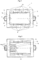
- the mobile device 1 has two identical, arranged on the same virtual axis of rotation 12 knobs I, II 8, 5, which are each equipped with an operable in the axial direction of buttons 9, 4, wherein the knobs I, II, 8, 5 to the vertical Housing sides of the mobile device 1 are located.
- a screen 3 is integrated in the form of an LCD display 7, which is present on the front of the mobile device 1.
- key elements 6, 13 are mounted at the top and at the bottom of the screen, which are lined up in a plan view of the mobile device 1 on parallel axes to the virtual axis of rotation 12.
- a menu window edge 11 is shown, which is designed such that a narrow plastic and cylindrical surface, the rotary knob I, 8 is similar to indicated.
- pressing the left button I, 9 is a previously inserted menu of the menu window edge 11 as a virtual roller 15 in the push-button direction, as shown FIG. 2 seen, pushed out. Now it is clear that this is the virtual replica of the cylindrical shape of the knob I, 8.
- a 3D-capable LCD display 7 On the virtual roller 15 described above, a plurality of menu items 14 are arranged according to the spatial cylinder structure. The symbol at the end of the menu bar 17 retains its not further described representation as arrow 16 in this menu state in order to inform the operator that to select the next submenu 18 described in the menu bar 17, this is pressed again by pressing the button I , 9 should press right in the picture plane of the screen 3. If the menu item 14 selected in the menu bar 17 does not correspond to the desired selection, the desired item is rotated into the menu bar 17 by turning the rotary knob I, 8. So is the rotary knob I, 8, as shown in FIG FIG.
- the virtual roller 15 rotates in the same way and the menu items 14 change their places accordingly according to the direction of rotation. It is therefore crucial that the menu bar 17 remains static, preferably at the level of the virtual axis of rotation 12, and a selected virtual roller 15 rotates below it.
- Another virtual roller 15 is pushed out to the right and offers new menu items 14 or at the end of the menu structure corresponding selection points 20 at.
- the menu bar 17 expands on the width of both virtual rollers 15 and describes the hitherto selected path 22 including the currently selected menu 21 and / or selection point 20. This path is important to check at any time, at which point in the menu system is currently located.
- the adjustment of the selection point 20 takes place in the same way as in accordance with FIG. 3 described.
- the symbol at the end of the menu bar 17 appears in a circle or arrow form to indicate whether the operator continues to advance in the menu structure when selecting the active menu 21 or selection point 20, or whether he activates or deactivates a selection point 20 .
- the content of the selection point 20 is thus an unspecified action / screen display, in which, for example, a higher-level setting window opens or the menu 21 is hidden after activation of the selection point 20.
- either the right button II, 4 is pressed once short or the button I, 9 for a defined long period of seconds less seconds to, as shown in FIG FIG. 4 , above FIG. 2 , back in the Starting view after FIG. 1 to get.
- the right button II, 4 can optionally only the left button I, 9 are pressed to return through the menu levels.
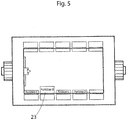
- the knob II, 5 is for the necessary adjustment in menu levels, as in FIG. 5 described, used. Functions for the right-hand rotary knob II, 5, if this is otherwise used for the control of a device by means of the mobile device 1, are not described in greater detail here.
- each pair acts like a physically present and virtually imaged key.
- an associated display form expands into the image plane of the screen 3 to indicate that this setting is now activated.
- Function values can then be adjusted or entered, preferably by turning the left-hand rotary knob I, 8, and these are already confirmed at the moment of adjustment.
- the setting of function values could also be effected by repeated pressing of the key elements 6, 13 or of the push-buttons I, 9, wherein when changing by pressing another key element 6, 13 can be changed immediately into the setting mode of the new key element 6, 13.
- the graphic display in the LCD display 7 goes back to its initial view when exiting, according to Fig. 1 , back and the confirmed setting of an activated key element 23 is permanently displayed. It is conceivable that all key pairs can vary freely according to the respective mode of operation of the mobile device 1 and are flexibly changeable by the marking in the area of the LCD display 7, if the need exists.
Landscapes
- Engineering & Computer Science (AREA)
- General Engineering & Computer Science (AREA)
- Theoretical Computer Science (AREA)
- Human Computer Interaction (AREA)
- Physics & Mathematics (AREA)
- General Physics & Mathematics (AREA)
- Chemical & Material Sciences (AREA)
- Combustion & Propulsion (AREA)
- Mechanical Engineering (AREA)
- Input From Keyboards Or The Like (AREA)
- User Interface Of Digital Computer (AREA)
Description
Die Erfindung betrifft eine mobile Einrichtung zur computergestützten Ein- und Ausgabe von Daten mit einer integrierten Bildschirmausgabeeinheit. Außerdem betrifft die Erfindung ein Verfahren zur Visualisierung der Bedienung der erfindungsgemäßen Einrichtung.The invention relates to a mobile device for computer-aided input and output of data with an integrated screen display unit. Moreover, the invention relates to a method for visualizing the operation of the device according to the invention.
Die Einrichtung ist in ihrem Anwendungsumfang nicht auf ein spezielles technisches Nutzerprofil festgelegt, denn sie kann aufgrund ihrer aus sich selbst heraus erklärenden Weise der Bedienung als Hardwarekomponente zur Realisierung von computergestützten Prozessen, beispielsweise in der Mess-, Steuerungs- und Regelungstechnik eingesetzt werden.The device is not specified in its scope of application to a specific technical user profile, because it can be used as a hardware component for the realization of computer-aided processes, for example in the measurement and control technology due to their self-explanatory manner of operation.
Bei der Konzeption von Geräten ist die Gestaltung der Mensch-Maschine-Schnittstelle aufgrund der technischen Umsetzungsmöglichkeiten in Bezug auf die Physiologie des Menschen oft noch problematisch bzw. die entstandene Umsetzung nicht immer selbsterklärend oder intuitiv.In the design of devices, the design of the human-machine interface is often still problematic because of the technical implementation possibilities in relation to the physiology of humans or the resulting implementation is not always self-explanatory or intuitive.
Zwar erschließt sich die Bedienung von Hebeln, Drehknöpfen und Tastern usw. aufgrund der weiten Verbreitung dieser Elemente meist sofort, aber oft mangelt es an eindeutigen Bezügen zwischen den physischen Eingabegeräten und der Reaktion bzw. der Interaktion auf dem Ausgabegerät. Gerade bei Geräten mit ausgedehntem Funktionsumfang und dadurch bedingter komplexer Bedienstruktur kommt diese Tatsache zum Tragen. Beispielsweise werden bei der Bedienung eines Personalcomputers (PC) mittels Computermaus tradierte Bedienmuster vorausgesetzt, die sich der Nutzer nur durch eine vorgeschaltete Anlernphase aneignen kann, wobei er beim Erlernen auf sein Abstraktionsvermögen angewiesen ist.Although the operation of levers, knobs, and buttons, etc., is usually immediately apparent due to the widespread use of these elements, there is often a lack of clear references between the physical input devices and the response or interaction on the output device. Especially with devices with extended functionality and the resulting complex operating structure, this fact comes into play. For example, in the operation of a personal computer (PC) by means of computer mouse traditional operating patterns are required, which the user can acquire only through an upstream learning phase, where he is dependent on his ability to abstract while learning.
Erst dann kann die Kommunikation reibungslos funktionieren, ist aber angesichts vieler nutzerseitiger Interpretationsmöglichkeiten fehleranfällig.Only then can communication function smoothly, but in the face of many user-side interpretation options, it is prone to error.
Das ist oft ungenügend und bietet weiteres Verbesserungspotential, zumal die Lösung auch technisch aufwändig, komplex und dementsprechend kostenintensiv in der Umsetzung ist. Daraus hervorgehend gibt es andere Lösungen, welche eine intuitivere Gerätebedienung ermöglichen. Beispielsweise bewegt sich der Nutzer eines modernen, mit Touchscreen ausgestattetem Smartphones über direkte Interaktion mittels wischen, tasten, ziehen, schütteln, neigen usw. durch die auf dem Bildschirm angezeigte Menüstruktur.This is often insufficient and offers further potential for improvement, especially as the solution is also technically complex, complex and accordingly costly to implement. As a result, there are other solutions that allow for more intuitive device operation. For example, the user is moving one modern, touch-screen smartphones use direct interaction to swipe, touch, drag, shake, tilt, etc. through the menu structure displayed on the screen.
In diesem druck- und neigungs-/beschleunigungssensitiven Gerät werden die Anzeigeinhalte auch oft dreidimensional dargestellt, wodurch beim Nutzer eine zweite, parallele, virtuelle Realität entsteht. Diese entspricht den grundlegenden Erfahrungen aus physiologischer Sicht viel eher. Dadurch verringert sich die Fehlerquote bei der Eingabe erheblich und die Anlernphase reduziert sich, bezogen auf das vorgehend beschriebene Modell, auf einen Bruchteil.In this pressure and tilt / acceleration sensitive device, the display contents are also often displayed in three dimensions, giving the user a second, parallel, virtual reality. This corresponds much more to the basic experience from a physiological point of view. As a result, the error rate when entering significantly reduced and the learning phase is reduced, based on the model described above, to a fraction.
Als ein dafür typisches Beispiel aus dem Stand der Technik kann
Aber auch diese Gerätelösung bedingt dafür im Gegenzug einen technisch aufwändigen und komplexen Aufbau und ist deswegen erst bei der Herstellung großer Stückzahlen umsetzbar und wirtschaftlich. Deshalb integrieren Hersteller bei kleineren Geräteserien immer noch konventionelle Eingabe-Einheiten, wie Knöpfe, Inkrementalgeber oder Hebel. Jedoch erschwert sich die Bedienung dieser Geräte und ist oft unverständlich, wenn sie einen vergleichbaren oder unwesentlich geringeren Funktionsumfang wie ein PC oder ein Smartphone haben, zur Steuerung dieser jedoch nur funktionell begrenzte oder zahlreiche bis unüberschaubar viele Eingabeelemente besitzen.But even this device solution requires in return a technically complex and complex structure and is therefore only in the production of large quantities feasible and economical. For this reason, manufacturers still integrate conventional input units such as buttons, incremental encoders or levers for smaller device series. However, the operation of these devices is difficult and is often incomprehensible if they have a comparable or insignificantly smaller range of functions such as a PC or a smartphone, for controlling this but only functionally limited or have numerous to unmanageable many input elements.
Nachteile des bekannten Standes der Technik müssen daher mit einer vergleichsweise einfachen und insbesondere in Kleinserien wirtschaftlich fertigbaren Einrichtung überwunden werden.Disadvantages of the known state of the art therefore have to be overcome with a comparatively simple and in particular in small batches economically manufacturable device.
Die Aufgabe der Erfindung besteht demnach darin, über einen inversen Zugang an einer Einrichtung konventionelle Bedienelemente mit einer modernen rechnergesteuerten Bildschirmausgabeeinheit zu kombinieren, wodurch über eine physiologisch leicht handhabbare Anordnung von Bedienelementen mit unkompliziert erschließbaren Freiheitsgraden eine aus sich heraus selbsterklärende und intuitive Ansteuerung eines technischen Gerätes erfolgen kann und vorhersehbare sowie erwartbare Reaktionen desselben über die Bildschirmausgabeeinheit nachverfolgbar sind.Accordingly, the object of the invention is to combine conventional operating elements with a modern computer-controlled screen output unit via an inverse access to a device, whereby a self-explanatory and intuitive control of a technical device can take place via a physiologically easily manageable arrangement of operating elements with degrees of freedom which can be developed easily can be traceable and predictable and expected reactions of the same via the screen output unit.
Mit einer derartigen benutzerfreundlichen Einrichtung und einem Verfahren zur Visualisierung der Bedienung derselben soll der Komfort intuitiver Interfaces mit den Anforderungen an eine wirtschaftliche Herstellung von Kleinserien verbunden werden. Die Aufgabe der Erfindung wird für die eingangs genannte mobile Einrichtung durch den Patentanspruch 1 und für das eingangs genannte Verfahren durch den Patentanspruch 5 gelöst. Die weitere Ausgestaltung der Erfindung wird in den Patentansprüchen 2 bis 4 sowie 6 bis 8 dargelegt.With such a user-friendly device and a method for visualizing the operation of the same, the convenience of intuitive interfaces should be combined with the requirements for economical production of small batches. The object of the invention is achieved for the above-mentioned mobile device by the
Zur Erläuterung der Erfindung sind weitere Hinweise erforderlich.To explain the invention further references are required.
Die Erfindung geht von einer mobilen Einrichtung zur computergestützten Ein- und Ausgabe von Daten mit einer integrierten und einen Bildschirm sowie ein Gehäuse aufweisenden Bildschirmausgabeeinheit aus, wobei an einem Paar gegenüberliegender Rechteckseiten außen am Gehäuse zwei Bedienelemente als in Links- und Rechtslauf ausgebildete zylinderförmige Drehknöpfe I, II mit jeweils axial angebrachtem Taster I, II angebracht sind, deren Drehachsen horizontal über die Bildebene des Bildschirms virtuell verlängert dargestellt werden, wobei mittels des Tasters ein Menü mit weiteren Untermenüs in Tasterdruckrichtung virtuell in die Bildebene geschoben wird.The invention relates to a mobile device for computer-aided input and output of data with an integrated and a screen and a housing having screen output unit, wherein on a pair of opposite sides of the rectangle outside the housing two controls as formed in left and right cylindrical rotating knobs I, II are mounted with each axially mounted button I, II, the axes of rotation are displayed horizontally extended virtually horizontally over the image plane of the screen, using the button a menu with further submenus in push-button direction is virtually pushed into the image plane.
Weiterhin sind Tastenelemente in paralleler Ausrichtung zu den Drehachsen der Drehknöpfe I und II an der Ober- und an der Unterseite des Bildschirms angeordnet, mit denen Einstellungen von den in den weiteren Untermenüs enthaltenen Funktionswerten auf dem Bildschirm aktivierbar sind, wobei sich die Untermenüs in einem oder in mehreren Menüs befinden und die Funktionswerte mittels realer Drehung am Drehknopf I und einer virtuell darstellbaren Drehung des Drehknopfes I auf dem Bildschirm verändert angezeigt werden und an einem ausgewählten Platz eines Untermenüs speicherbar sind. Die mobile Einrichtung hat als Handgerät den Vorteil, dass sie während der Bedienung nicht abgelegt werden muss und die auf ein Minimum reduzierten Elemente zur Handhabung alle erforderlichen Tätigkeiten zulassen. Jede Drehbewegung an einem der Drehknöpfe I, II, jede Betätigung eines Tasters I, II an den Drehknöpfen I, II und jede Berührung eines der am oberen und am unteren Bildschirmrand angeordneten Tastenelemente bildet einen auf der Bildschirmausgabeeinheit nachverfolgbaren Pfad ab, so dass der Bediener kein abstraktes Vorstellungsvermögen entwickeln muss, um seine Bedienhandlungen logisch zu verstehen, da er sie simultan optisch angezeigt bekommt.Furthermore, key elements are arranged in parallel alignment with the axes of rotation of the knobs I and II at the top and at the bottom of the screen, with which settings of the function values contained in the other submenus can be activated on the screen, wherein the submenus are located in one or more menus and the function values displayed on the screen changed by means of real rotation on the rotary knob I and a virtually representable rotation of the knob I and can be stored at a selected location of a submenu. As a handheld device, the mobile device has the advantage that it does not have to be stored during operation and that the elements reduced to a minimum permit handling of all required activities. Each rotation of one of the knobs I, II, each actuation of a button I, II on the knobs I, II and each touch of one of the upper and the lower edge of the screen arranged button elements maps a traceable on the screen display unit path, so that the operator no abstract imagination has to develop in order to logically understand his operations, since he gets them visually displayed simultaneously.
Der Drehknopf I und der Drehknopf II ist jeweils mit einem axial angebrachten Taster I, II ausgestattet. Das hat den Vorteil, dass auf einer virtuellen Drehachse, die die beiden Drehknöpfe I, II über den Bildschirm der Bildschirmausgabeeinheit miteinander verbindet, ein oder mehrere Menüpunkte in Form einer rotierenden Walze vom linken Bildschirmrand in die Bildebene hinein oder wieder zurück in Richtung des Ausgangszustandes geschoben werden können.The knob I and the knob II is each equipped with an axially mounted button I, II. This has the advantage that on a virtual axis of rotation, which connects the two rotary knobs I, II via the screen of the screen output unit, one or more menu items in the form of a rotating roller from the left edge of the screen into the image plane or pushed back towards the initial state can be.
Zur Verdeutlichung der Handlungen an der mobilen Einrichtung besitzt diese einen Bildschirm der ausgelegt ist, die Wiedergabe der Bedienung in zwei- oder in dreidimensionaler Abbildung vorzunehmen.To illustrate the actions on the mobile device this has a screen which is designed to make the playback of the operation in two- or in three-dimensional image.
Damit ist optisch in anschaulicher Weise die Körperlichkeit der Drehknöpfe I, II, der Taster I, II, der Tastenelemente und der Pfad ihrer gegebenenfalls derzeitigen Aktivierung darstellbar und der Benutzer ist optisch besser darüber informiert, an welcher Stelle eines Menüs oder Untermenüs er sich gerade befindet. Es kann damit vorteilhafterweise auch eine Selbstkontrolle über ausgeführte Handlungen durchgeführt werden.This is visually vividly the physicality of the knobs I, II, the button I, II, the key elements and the path of their possibly current activation displayed and the user is visually better informed at which point of a menu or submenu he is currently , It can thus be advantageously carried out a self-control of executed actions.
Ferner ist die mobile Einrichtung derart ausgebildet, dass der Bildschirm der Bildschirmausgabeeinheit einen Drehknopf I als eine in räumlicher Form dargestellte Walze mit einem Menübalken, auf der einzelne Menüpunkte aufrufbarer Untermenüs aufgetragen sind, zeigt, wobei die Darstellung des Drehknopfes I horizontal in axialer Richtung zur Symbolisierung des gespeicherten Inhaltes, seitlich in die Bildebene hinein mehrfach fortsetzbar ist. Dadurch wird die reale Drehung, nach Einschieben eines Menüs in die Bildebene, des Drehknopfes I in das virtuelle Abbild der rotierenden Walze im Bildschirm der Bildschirmausgabeeinheit "übersetzt" und es kann gleichzeitig erkannt werden, mit welchen Untermenüs die Walze besetzt ist.Furthermore, the mobile device is designed such that the screen of the screen display unit shows a knob I as a spatially represented roller with a menu bar on which individual menu items callable submenus are applied, wherein the representation of the knob I horizontally in the axial direction for symbolization the stored content, laterally in the image plane is repeatedly weiteretzbar. Thereby, the real rotation, after inserting a menu in the image plane of the rotary knob I in the virtual image of the rotating roller in the screen of the screen output unit "translated" and it can be recognized at the same time, which submenus the roller is occupied.
Die Auswahl eines Untermenüs auf einer Walze ist durch Rotation derselben unter einen statisch auf der Drehachse verbleibenden Menübalken gegeben, wobei ein Taster I des Drehknopfes I am Ende des Menübalkens auf dem Bildschirm als kreisförmiges Symbol dargestellt ist oder, wenn an der Stelle ein weiteres Untermenü am Menübalken aufrufbar ist, eine horizontale Pfeilform aufweist.
Hierdurch kann sofort erkannt werden, ob und welche Untermenüs einen weiteren vertiefenden Erkenntnisgewinn erwarten lassen.The selection of a submenu on a roller is given by rotation of the latter below a menu bar remaining statically on the axis of rotation, wherein a button I of the rotary knob I at the end of the menu bar is displayed on the screen as a circular symbol or, if at that point, another submenu at Menu bar is callable, has a horizontal arrow shape.
As a result, it can be immediately recognized whether and which submenus can be expected to provide further in-depth knowledge gain.
Die Ausgestaltung der Erfindung zeigt ferner, dass der Drehknopf II eine Verstellfunktion zur Bewegung in einem aufgerufenen Untermenü besitzen kann. Auch diese Handlung ist vorteilhafterweise auf dem Bildschirm darstellbar, wobei der Drehknopf II auch mit anderen - durch Software unterstützte Funktionen - belegt werden kann.The embodiment of the invention also shows that the rotary knob II can have an adjustment function for movement in a called submenu. Also, this action is advantageously displayed on the screen, the knob II can also with other - supported by software functions - can be assigned.
Es kann vorgesehen werden, dass der Taster II am Drehknopf II als ein Element des Schließens des gesamten Menüs oder von allen virtuell sichtbaren Walzen, in Gestalt des Drehknopfes I, ausgebildet ist. Andererseits kann durch längeres Drücken des Tasters I in optisch nachverfolgbarer Weise der Aufruf eines Menüs rückgängig gemacht werden. Ferner kann der Taster II am Drehknopf II eingerichtet sein, durch eine kurze einmalige Betätigung eine Rückwärtsbewegung durch Ebenen des Menüs auszuführen.It can be provided that the button II on the knob II as an element of the closing of the entire menu or of all virtually visible rollers, in the form of the knob I, is formed. On the other hand, by prolonged pressing of the button I in an optically traceable way the call of a menu can be reversed. Further, the button II may be configured on the rotary knob II to perform a backward movement through levels of the menu by a short one-time operation.
Ferner ist die Erfindung dahingehend ausgestaltet, dass Tastenelemente am oberen und unteren Bildrand des Bildschirms der Bildschirmausgabeeinheit vorgesehen sind und sich spiegelbildlich unmittelbar am jeweiligen Rand auf der Gehäuseoberfläche und auf dem Bildschirm gegenüberliegen. Dadurch ist eine sofortige visuelle Kontrolle gegeben, weiches Tastenelement gerade aktiviert ist, da es grafisch hervorgehoben in den Bildschirm expandiert.Further, the invention is designed such that key elements are provided at the upper and lower edges of the screen of the screen output unit and are mirror images directly opposite to the respective edge on the housing surface and on the screen. This gives an immediate visual control that is just activated on the key element as it graphically expands into the screen.
Damit die Symbolik auf dem Bildschirm der Bildschirmausgabeeinheit unverwechselbar wahrgenommen wird, ist es von Vorteil, wenn der Bildschirm der Bildschirmausgabeeinheit in Form eines LCD-Displays vorliegt.In order that the symbolism is perceived unmistakably on the screen of the screen output unit, it is advantageous if the screen of the screen output unit is in the form of an LCD display.
Mit der mobilen Einrichtung ist ein Verfahren zur Visualisierung ihrer Bedienung realisierbar, wobei mittels seitlichen, horizontalen manuellen Drucks, einmal oder mehrmals auf einen Taster I am Drehknopf I ein Menü mit weiteren Untermenüs als um eine gedachte horizontale Achse rotierende Walze in einen Teilbereich eines Bildschirms einer Bildschirmausgabeeinheit translatorisch bewegt wird und mittels anschließender Drehung am Drehknopf ein Menüpunkt eines Untermenüs unter einen Menübalken der rotierbaren virtuellen Walze positioniert und das Untermenü dort durch Aktivierung eines Einstellfensters geöffnet wird, wobei über den Drehknopf I neue oder zu verändernde Funktionswerte an den Stellen aktivierter Tastenelemente, die variabel belegbar sind, in ein geöffnetes Untermenü eingelesen werden, die sofort nach Verlassen des jeweiligen Untermenüs und Wechseln in ein anderes Untermenü und/oder Menü gespeichert werden.With the mobile device is a method for visualization of their operation feasible, by means of lateral, horizontal manual pressure, one or more times on a button I on the knob I a menu with other submenus as an imaginary horizontal axis rotating roller in a portion of a screen Screen output unit is moved translationally and positioned by means of subsequent rotation of the knob a menu item of a submenu under a menu bar of the rotatable virtual roller and the submenu there is opened by activating an adjustment window, via the knob I new or to be changed function values at the locations of activated key elements, the can be variably assigned, are read into an open submenu, which are stored immediately after leaving the respective submenu and changing to another submenu and / or menu.
Weiterhin ist es mit dem Verfahren zur Visualisierung der Bedienung der Einrichtung möglich, dass durch die Betätigung der Tastenelemente auf der Gehäuseoberfläche eine definierte Expansion und virtuelle Darstellung in die Bildebene des aktivierten Tastenelementes am Bildrand des Bildschirms durchgeführt wird.Furthermore, it is possible with the method for visualization of the operation of the device that a defined expansion and virtual representation in the image plane of the activated key element at the edge of the screen is performed by the operation of the key elements on the housing surface.
Ferner bezieht das mit der mobilen Einrichtung realisierbare Verfahren ein, dass durch manuellen Druck auf den Taster II am Drehknopf II ein mit seinen aufgerufenen Untermenüs geöffnetes Menü sofort geschlossen werden kann, wobei jedoch durch definiert längeres Drücken des Tasters I am Drehknopf I auch eine stufenweise Rückführung in eine erste Menüebene durchgeführt werden kann .Furthermore, the realizable with the mobile device method involves that by manual pressure on the button II on the knob II opened with his called submenus menu can be immediately closed, but by defined longer pressing the button I on the knob I and a gradual feedback can be performed in a first menu level.
Schließlich kann der Drehknopf II mit einer anderen Funktion belegt werden, wobei er zur Eingabe von Funktionswerten verwendet wird.Finally, the rotary knob II can be assigned a different function, whereby it is used to input function values.
Die Erfindung soll anhand eines Ausführungsbeispiels näher erläutert werden. Dazu werden die nachfolgend angegebenen
Es zeigen:
Figur 1- mobile Einrichtung eingeschaltet, Ausgangsansicht - Draufsicht von oben,
Figur 2- wie
Figur 1 Figur 3- wie
Figur 2 Figur 4wie Figur 2 , jedoch mit einem weiteren horizontal nach rechts bewegten und aktivierten Menü,Figur 5wie Figur 1 , jedoch mit einem aktivierten Tastenelement am unteren Bildrand des Bildschirms.
- FIG. 1
- mobile device switched on, output view - top view from above,
- FIG. 2
- as
FIG. 1 but with an activated menu together with visible menu items of invokable submenus, - FIG. 3
- as
FIG. 2 but with revolving roller of a menu, - FIG. 4
- as
FIG. 2 but with another horizontally right-moved and activated menu, - FIG. 5
- as
FIG. 1 but with an activated button element at the bottom of the screen.
Nach
Auf dem LCD-Display ist im Ausgangszustand nach
Der plastische Effekt ließe sich durch den Einsatz eines 3D-fähigen LCD-Displays 7 noch weiter verstärken. Auf der oben beschriebenen virtuellen Walze 15 sind entsprechend der räumlichen Zylinderstruktur mehrere Menüpunkte 14 angeordnet. Das Symbol am Endes des Menübalkens 17 behält in diesem Menüzustand seine nicht weiter beschriebene Darstellung als Pfeil 16, um den Bediener darauf hinzuweisen, dass er, um das nächste, im Menübalken 17 beschriebene Untermenü 18 auszuwählen, dieses durch einen weiteren Druck auf den Taster I, 9 nach rechts in die Bildebene des Bildschirms 3 drücken soll. Entspricht der im Menübalken 17 gewählte Menüpunkt 14 nicht der gewünschten Auswahl, wird der gewünschte mittels Drehen des Drehknopfes I, 8 in den Menübalken 17 rotiert. Wird also am Drehknopf I, 8, wie gemäß
Durch erneuten Druck auf den Taster I, 9 ergibt sich für das gewählte Menü ein Zustand, wie gemäß
Die Verstellung des Auswahlpunktes 20 erfolgt auf die gleiche Weise wie gemäß
Im Falle einer Rückwärtsbewegung durch die verschiedenen Menüebenen werden entsprechend der bisher beschriebenen Logik entweder der rechte Taster II, 4 einmalig kurz oder der Taster I, 9 für eine definiert lange Zeitspanne weniger Sekunden gedrückt, um gemäß der Darstellung in
Der Drehknopf II, 5 wird für die in Menüebenen notwendige Verstellfunktion, wie in
Schließlich ist noch die Arbeitsweise mit den Tastenelementen 6, 13 nach
Durch die räumliche Nähe und die gleichen Größen- und Farbverhältnisse der physisch vorhandenen Tastenelemente 6, 13 und der auf dem LCD-Display 7 abgebildeten Tastenelemente 23 wirkt jedes Paar wie eine physisch vorhandene und virtuell abgebildete Taste. Durch den Druck auf ein beliebiges Tasterelement 6, 13 expandiert eine dazugehörige Displayform in die Bildebene des Bildschirms 3, um anzuzeigen, dass diese Einstellung nun aktiviert ist. Funktionswerte können sodann, vorzugsweise durch Drehen des linken Drehknopfes I, 8 verstellt oder eingegeben werden und es sind diese im Moment des Verstellens bereits bestätigt. Optional könnte die Einstellung von Funktionswerten auch mittels mehrmaligen Drückens der Tastenelemente 6, 13 oder des Tasters I, 9 erfolgen, wobei beim Wechsel durch Drücken eines anderen Tastenelementes 6, 13 sofort in den Einstellmodus des neuen Tastenelementes 6, 13 gewechselt werden kann. In allen Fällen geht die grafische Darstellung im LCD-Display 7 beim Verlassen wieder in ihre Ausgangsansicht, gemäß
- 11
- mobile Einrichtungmobile device
- 22
- Gehäuseoberflächehousing surface
- 33
- Bildschirmscreen
- 44
- Taster IIButton II
- 55
- Drehknopf IIKnob II
- 66
- Tastenelementkey element
- 77
- LCD-DisplayLCD display
- 88th
- Drehknopf IKnob I
- 99
- Taster IPushbutton I
- 1010
- Symbolsymbol
- 1111
- MenüfensterkanteMenu window edge
- 1212
- virtuelle Drehachsevirtual axis of rotation
- 1313
- Tastenelementkey element
- 1414
- Menüpunktmenu item
- 1515
- virtuelle Walzevirtual roller
- 1616
- Pfeilarrow
- 1717
- Menübalkenmenu bar
- 1818
- Untermenüsubmenu
- 1919
- Links- und RechtslaufLeft and right rotation
- 2020
- Auswahlpunktselection point
- 2121
- Menümenu
- 2222
- Pfadpath
- 2323
- Tastenelement, aktiviertButton element, activated
Claims (8)
- Mobile device for computer-assisted input and output of data with an integrated screen output unit comprising a screen (3) and a housing, characterized in that two operation elements are attached to a pair of opposite rectangles sides outside at the housing as cylindrical rotary knobs I, II (8, 5) designed in left- and right course
and having an axially mounted button I, II (9, 4), respectively, whose rotation axes (12) are represented horizontally over the image plane of the screen (3) in a virtually extended manner,
wherein a menu (21) having further sub-menus (18) is pushed virtually into the image plane in the button push direction by means of the button I (9), and
wherein button elements (6, 13) are arranged at the upper and on the lower side of the screen (3) in parallel alignment to the rotation axis (3) of rotary knob I (8) and rotary knob II (5) by which settings of the function values contained in the further sub-menus (18) can be activated on the screen (3),
wherein the sub-menus (18) are located in one or more menus (21), and the function values are displayed on the screen (3) in an altered manner by a real rotation of the rotary button I (8) and
by a virtually representable rotation of the rotary knob I (8) and can be stored in a selected place of a sub-menu (18). - Mobile device according to claim 1, characterized in that the screen (3) of the screen output unit displays the rotary knob I (8) as a roller (15) represented in spatial form with a menu bar (17) on which individual menu items (14) of addressable sub-menus (18) are applied,
wherein the representation of the rotary knob I (8) can be repeatedly continued horizontally in axial direction laterally into the image plane in order to symbolize the stored content. - Mobile device according to claim 1, characterized in that the button elements (6, 13) on the upper and lower image edge of the screen (3) of the screen output unit are opposite each other in a mirror image manner directly at the respective edge on the housing surface (2) and on the screen (3).
- Mobile device according to one of the preceding claims, characterized in that the screen (3) of the screen output unit is a LCD-display (7).
- Method for visualizing the operation of the device according to claim 1, characterized in that
a menu (21) with further sub-menus (18) is moved translationally into a sub-region of a screen (3) of a screen output unit
as a roller rotating around a virtual horizontal axis,
by means of a lateral, horizontal, manual pressure on a button I (9) at the rotary knob (8) for one or more times,
and a menu item (14) of a sub-menu (18) is positioned under a menu bar (17) of the rotatable virtual roller by a subsequent rotation of the rotary knob (8),
and the sub-menu (18) is opened there by activating a setting window,
wherein a path (22) for further activable menus (21) with respective sub-menus (18)
that are drawn into the screen (3) of the screen output unit from left to right along the virtual axis between the rotary knob I (8) and the rotary knob II (5) is indicated by means of an arrow (16) placed on a menu item (14) of a sub-menu (18),
wherein, via the rotary knob I (8), new function values or function values to be changed,
at the places of activated button elements (6, 13) that can be variably programmed, are read in an opened sub-menu (18), which function values are stored immediately after leaving the respective sub-menu (18) and changing to another sub-menu (18) and/or menu (21). - Method for visualizing the operation of the device according to claim 5, characterized in that, by actuating the button elements (6, 13) at the housing surface, a defined expansion and virtual representation into the image plane of the activated button element (6, 13) are effectuated at the image edge of the screen (3).
- Method for visualizing the operation of the device according to claim 5 or 6, characterized in that, by manual pressure onto the button II (4) at the rotary knob II (5), a menu (21) opened with its called-up sub-menus (18) is immediately closed, but in which a return to a first plane of the menu (21) is effectuated by pressing the button I (9) of the rotary knob I (8) longer in a defined way.
- Method for visualizing the operation of the device according to claims 5 to 7, characterized in that the rotary knob II (5) is used to enter function values.
Applications Claiming Priority (1)
| Application Number | Priority Date | Filing Date | Title |
|---|---|---|---|
| DE102012200129A DE102012200129A1 (en) | 2012-01-05 | 2012-01-05 | Mobile device for computer-aided input and output of data with an integrated screen output unit and method for visualizing its operation |
Publications (2)
| Publication Number | Publication Date |
|---|---|
| EP2613239A1 EP2613239A1 (en) | 2013-07-10 |
| EP2613239B1 true EP2613239B1 (en) | 2018-10-03 |
Family
ID=47351391
Family Applications (1)
| Application Number | Title | Priority Date | Filing Date |
|---|---|---|---|
| EP12187897.9A Active EP2613239B1 (en) | 2012-01-05 | 2012-10-10 | Mobile device for computer-assisted input and output of data with an integrated screen output unit and method for visualizing its operation |
Country Status (2)
| Country | Link |
|---|---|
| EP (1) | EP2613239B1 (en) |
| DE (2) | DE202012013272U1 (en) |
Families Citing this family (3)
| Publication number | Priority date | Publication date | Assignee | Title |
|---|---|---|---|---|
| WO2016042365A1 (en) * | 2014-09-20 | 2016-03-24 | 南宁马许科技有限公司 | Dial-type information input device |
| CN108008836B (en) * | 2018-01-03 | 2024-04-23 | 联想(北京)有限公司 | Input device and input control method for electronic equipment |
| CN111232232B (en) * | 2019-12-30 | 2023-08-29 | 成都赫尔墨斯科技股份有限公司 | Device and method for comprehensive display control of avionics equipment |
Family Cites Families (7)
| Publication number | Priority date | Publication date | Assignee | Title |
|---|---|---|---|---|
| CN1183431C (en) * | 1998-03-05 | 2005-01-05 | 三菱电机株式会社 | Portable terminal |
| GB2382292A (en) * | 2001-11-17 | 2003-05-21 | Oliver Wallington | Digital display with scrolling means |
| DE10339185A1 (en) * | 2003-03-28 | 2005-04-07 | Micronas Gmbh | Apparatus and method for searching and manipulating data in a mass storage device |
| DE202006000158U1 (en) * | 2006-01-07 | 2007-05-24 | Dugi, Zelimir, Dipl.-Ing. | Control-input device e.g. control-input joystick, for e.g. mobile telephone, has switching arrangement simultaneously implementing switching operations via positioning device, where perceptible wet switching row is produced via device |
| US7966578B2 (en) | 2007-01-07 | 2011-06-21 | Apple Inc. | Portable multifunction device, method, and graphical user interface for translating displayed content |
| US8185170B2 (en) * | 2008-03-28 | 2012-05-22 | Kyocera Corporation | Portable electronic apparatus |
| DE102009034913A1 (en) * | 2009-07-28 | 2011-02-03 | GM Global Technology Operations, Inc., Detroit | Operating and display device for a vehicle |
-
2012
- 2012-01-05 DE DE202012013272.5U patent/DE202012013272U1/en not_active Expired - Lifetime
- 2012-01-05 DE DE102012200129A patent/DE102012200129A1/en not_active Withdrawn
- 2012-10-10 EP EP12187897.9A patent/EP2613239B1/en active Active
Also Published As
| Publication number | Publication date |
|---|---|
| DE102012200129A1 (en) | 2013-07-11 |
| DE202012013272U1 (en) | 2015-11-16 |
| EP2613239A1 (en) | 2013-07-10 |
Similar Documents
| Publication | Publication Date | Title |
|---|---|---|
| EP1262740B1 (en) | Vehicle computer system and method for controlling a cursor for a vehicle computer system | |
| DE4446431C2 (en) | Process for direct manipulation of images on a monitor with a mouse | |
| EP2062121B1 (en) | Touchpad or touchscreen and control element for a touchpad or touchscreen | |
| DE102015218518A1 (en) | Innovative rotary knob with variable haptic feedback | |
| DE202011106885U1 (en) | mode switching | |
| EP2100197A1 (en) | Operating unit with touchscreen keys | |
| EP3270278B1 (en) | Method for operating an operating system and operating system | |
| EP1374027B1 (en) | Positioning of areas displayed on a user interface | |
| EP2822814B1 (en) | Motor vehicle with an electronic rear view mirror | |
| EP3036126A1 (en) | Operating method for an operating and display device in a vehicle and operating and display device in a vehicle | |
| EP2828056A1 (en) | Device and method for operating a machine equipped with a handling device | |
| DE102012220062A1 (en) | SETTING MULTIPLE USER INPUT PARAMETERS | |
| DE102016202694A1 (en) | Multi-ad user interface and method for positioning content across multiple ads | |
| EP2613239B1 (en) | Mobile device for computer-assisted input and output of data with an integrated screen output unit and method for visualizing its operation | |
| WO2017186369A1 (en) | Operating panel for controlling an industrial installation | |
| EP0525531A2 (en) | Control panel for processing and measuring machines | |
| AT509779A1 (en) | TOUCH SENSITIVE SCREEN | |
| EP0972618A2 (en) | Cutting machine for cutting stacked sheet material | |
| DE112004001937T5 (en) | Haptic input device for generating control information | |
| EP3662345B1 (en) | Control device for industrial machines | |
| DE102018202668B4 (en) | Operating device and method for controlling at least one functional unit for a motor vehicle with an optical displacement of an operating symbol | |
| WO2000017740A1 (en) | Method for representing graphic operating elements of a graphic user surface | |
| EP3542235B1 (en) | Interactively controlling a machine with feedback from a control parameter | |
| DE10201193A1 (en) | Computer mouse has additional command buttons that are positioned in the center of the mouse and improve functionality by enabling additional manipulation of windows on the computer display | |
| DE102013206806B4 (en) | Method for operating a printing machine |
Legal Events
| Date | Code | Title | Description |
|---|---|---|---|
| PUAI | Public reference made under article 153(3) epc to a published international application that has entered the european phase |
Free format text: ORIGINAL CODE: 0009012 |
|
| AK | Designated contracting states |
Kind code of ref document: A1 Designated state(s): AL AT BE BG CH CY CZ DE DK EE ES FI FR GB GR HR HU IE IS IT LI LT LU LV MC MK MT NL NO PL PT RO RS SE SI SK SM TR |
|
| AX | Request for extension of the european patent |
Extension state: BA ME |
|
| 17P | Request for examination filed |
Effective date: 20131218 |
|
| RBV | Designated contracting states (corrected) |
Designated state(s): AL AT BE BG CH CY CZ DE DK EE ES FI FR GB GR HR HU IE IS IT LI LT LU LV MC MK MT NL NO PL PT RO RS SE SI SK SM TR |
|
| 17Q | First examination report despatched |
Effective date: 20160802 |
|
| GRAP | Despatch of communication of intention to grant a patent |
Free format text: ORIGINAL CODE: EPIDOSNIGR1 |
|
| INTG | Intention to grant announced |
Effective date: 20180508 |
|
| GRAS | Grant fee paid |
Free format text: ORIGINAL CODE: EPIDOSNIGR3 |
|
| GRAA | (expected) grant |
Free format text: ORIGINAL CODE: 0009210 |
|
| AK | Designated contracting states |
Kind code of ref document: B1 Designated state(s): AL AT BE BG CH CY CZ DE DK EE ES FI FR GB GR HR HU IE IS IT LI LT LU LV MC MK MT NL NO PL PT RO RS SE SI SK SM TR |
|
| REG | Reference to a national code |
Ref country code: GB Ref legal event code: FG4D Free format text: NOT ENGLISH |
|
| REG | Reference to a national code |
Ref country code: CH Ref legal event code: EP Ref country code: AT Ref legal event code: REF Ref document number: 1049324 Country of ref document: AT Kind code of ref document: T Effective date: 20181015 |
|
| REG | Reference to a national code |
Ref country code: IE Ref legal event code: FG4D Free format text: LANGUAGE OF EP DOCUMENT: GERMAN Ref country code: DE Ref legal event code: R096 Ref document number: 502012013535 Country of ref document: DE |
|
| REG | Reference to a national code |
Ref country code: NL Ref legal event code: MP Effective date: 20181003 |
|
| REG | Reference to a national code |
Ref country code: LT Ref legal event code: MG4D |
|
| PG25 | Lapsed in a contracting state [announced via postgrant information from national office to epo] |
Ref country code: NL Free format text: LAPSE BECAUSE OF FAILURE TO SUBMIT A TRANSLATION OF THE DESCRIPTION OR TO PAY THE FEE WITHIN THE PRESCRIBED TIME-LIMIT Effective date: 20181003 |
|
| PG25 | Lapsed in a contracting state [announced via postgrant information from national office to epo] |
Ref country code: IS Free format text: LAPSE BECAUSE OF FAILURE TO SUBMIT A TRANSLATION OF THE DESCRIPTION OR TO PAY THE FEE WITHIN THE PRESCRIBED TIME-LIMIT Effective date: 20190203 Ref country code: FI Free format text: LAPSE BECAUSE OF FAILURE TO SUBMIT A TRANSLATION OF THE DESCRIPTION OR TO PAY THE FEE WITHIN THE PRESCRIBED TIME-LIMIT Effective date: 20181003 Ref country code: LV Free format text: LAPSE BECAUSE OF FAILURE TO SUBMIT A TRANSLATION OF THE DESCRIPTION OR TO PAY THE FEE WITHIN THE PRESCRIBED TIME-LIMIT Effective date: 20181003 Ref country code: PL Free format text: LAPSE BECAUSE OF FAILURE TO SUBMIT A TRANSLATION OF THE DESCRIPTION OR TO PAY THE FEE WITHIN THE PRESCRIBED TIME-LIMIT Effective date: 20181003 Ref country code: LT Free format text: LAPSE BECAUSE OF FAILURE TO SUBMIT A TRANSLATION OF THE DESCRIPTION OR TO PAY THE FEE WITHIN THE PRESCRIBED TIME-LIMIT Effective date: 20181003 Ref country code: HR Free format text: LAPSE BECAUSE OF FAILURE TO SUBMIT A TRANSLATION OF THE DESCRIPTION OR TO PAY THE FEE WITHIN THE PRESCRIBED TIME-LIMIT Effective date: 20181003 Ref country code: NO Free format text: LAPSE BECAUSE OF FAILURE TO SUBMIT A TRANSLATION OF THE DESCRIPTION OR TO PAY THE FEE WITHIN THE PRESCRIBED TIME-LIMIT Effective date: 20190103 Ref country code: CZ Free format text: LAPSE BECAUSE OF FAILURE TO SUBMIT A TRANSLATION OF THE DESCRIPTION OR TO PAY THE FEE WITHIN THE PRESCRIBED TIME-LIMIT Effective date: 20181003 Ref country code: BG Free format text: LAPSE BECAUSE OF FAILURE TO SUBMIT A TRANSLATION OF THE DESCRIPTION OR TO PAY THE FEE WITHIN THE PRESCRIBED TIME-LIMIT Effective date: 20190103 Ref country code: ES Free format text: LAPSE BECAUSE OF FAILURE TO SUBMIT A TRANSLATION OF THE DESCRIPTION OR TO PAY THE FEE WITHIN THE PRESCRIBED TIME-LIMIT Effective date: 20181003 |
|
| PG25 | Lapsed in a contracting state [announced via postgrant information from national office to epo] |
Ref country code: PT Free format text: LAPSE BECAUSE OF FAILURE TO SUBMIT A TRANSLATION OF THE DESCRIPTION OR TO PAY THE FEE WITHIN THE PRESCRIBED TIME-LIMIT Effective date: 20190203 Ref country code: RS Free format text: LAPSE BECAUSE OF FAILURE TO SUBMIT A TRANSLATION OF THE DESCRIPTION OR TO PAY THE FEE WITHIN THE PRESCRIBED TIME-LIMIT Effective date: 20181003 Ref country code: SE Free format text: LAPSE BECAUSE OF FAILURE TO SUBMIT A TRANSLATION OF THE DESCRIPTION OR TO PAY THE FEE WITHIN THE PRESCRIBED TIME-LIMIT Effective date: 20181003 Ref country code: GR Free format text: LAPSE BECAUSE OF FAILURE TO SUBMIT A TRANSLATION OF THE DESCRIPTION OR TO PAY THE FEE WITHIN THE PRESCRIBED TIME-LIMIT Effective date: 20190104 Ref country code: AL Free format text: LAPSE BECAUSE OF FAILURE TO SUBMIT A TRANSLATION OF THE DESCRIPTION OR TO PAY THE FEE WITHIN THE PRESCRIBED TIME-LIMIT Effective date: 20181003 |
|
| REG | Reference to a national code |
Ref country code: CH Ref legal event code: PL |
|
| REG | Reference to a national code |
Ref country code: BE Ref legal event code: MM Effective date: 20181031 |
|
| PG25 | Lapsed in a contracting state [announced via postgrant information from national office to epo] |
Ref country code: LU Free format text: LAPSE BECAUSE OF NON-PAYMENT OF DUE FEES Effective date: 20181010 |
|
| REG | Reference to a national code |
Ref country code: DE Ref legal event code: R097 Ref document number: 502012013535 Country of ref document: DE |
|
| REG | Reference to a national code |
Ref country code: IE Ref legal event code: MM4A |
|
| PG25 | Lapsed in a contracting state [announced via postgrant information from national office to epo] |
Ref country code: IT Free format text: LAPSE BECAUSE OF FAILURE TO SUBMIT A TRANSLATION OF THE DESCRIPTION OR TO PAY THE FEE WITHIN THE PRESCRIBED TIME-LIMIT Effective date: 20181003 Ref country code: DK Free format text: LAPSE BECAUSE OF FAILURE TO SUBMIT A TRANSLATION OF THE DESCRIPTION OR TO PAY THE FEE WITHIN THE PRESCRIBED TIME-LIMIT Effective date: 20181003 |
|
| PLBE | No opposition filed within time limit |
Free format text: ORIGINAL CODE: 0009261 |
|
| STAA | Information on the status of an ep patent application or granted ep patent |
Free format text: STATUS: NO OPPOSITION FILED WITHIN TIME LIMIT |
|
| PG25 | Lapsed in a contracting state [announced via postgrant information from national office to epo] |
Ref country code: MC Free format text: LAPSE BECAUSE OF FAILURE TO SUBMIT A TRANSLATION OF THE DESCRIPTION OR TO PAY THE FEE WITHIN THE PRESCRIBED TIME-LIMIT Effective date: 20181003 Ref country code: SM Free format text: LAPSE BECAUSE OF FAILURE TO SUBMIT A TRANSLATION OF THE DESCRIPTION OR TO PAY THE FEE WITHIN THE PRESCRIBED TIME-LIMIT Effective date: 20181003 Ref country code: EE Free format text: LAPSE BECAUSE OF FAILURE TO SUBMIT A TRANSLATION OF THE DESCRIPTION OR TO PAY THE FEE WITHIN THE PRESCRIBED TIME-LIMIT Effective date: 20181003 Ref country code: RO Free format text: LAPSE BECAUSE OF FAILURE TO SUBMIT A TRANSLATION OF THE DESCRIPTION OR TO PAY THE FEE WITHIN THE PRESCRIBED TIME-LIMIT Effective date: 20181003 Ref country code: CH Free format text: LAPSE BECAUSE OF NON-PAYMENT OF DUE FEES Effective date: 20181031 Ref country code: BE Free format text: LAPSE BECAUSE OF NON-PAYMENT OF DUE FEES Effective date: 20181031 Ref country code: SK Free format text: LAPSE BECAUSE OF FAILURE TO SUBMIT A TRANSLATION OF THE DESCRIPTION OR TO PAY THE FEE WITHIN THE PRESCRIBED TIME-LIMIT Effective date: 20181003 Ref country code: LI Free format text: LAPSE BECAUSE OF NON-PAYMENT OF DUE FEES Effective date: 20181031 |
|
| 26N | No opposition filed |
Effective date: 20190704 |
|
| GBPC | Gb: european patent ceased through non-payment of renewal fee |
Effective date: 20190103 |
|
| PG25 | Lapsed in a contracting state [announced via postgrant information from national office to epo] |
Ref country code: IE Free format text: LAPSE BECAUSE OF NON-PAYMENT OF DUE FEES Effective date: 20181010 Ref country code: SI Free format text: LAPSE BECAUSE OF FAILURE TO SUBMIT A TRANSLATION OF THE DESCRIPTION OR TO PAY THE FEE WITHIN THE PRESCRIBED TIME-LIMIT Effective date: 20181003 Ref country code: FR Free format text: LAPSE BECAUSE OF NON-PAYMENT OF DUE FEES Effective date: 20181203 |
|
| REG | Reference to a national code |
Ref country code: AT Ref legal event code: MM01 Ref document number: 1049324 Country of ref document: AT Kind code of ref document: T Effective date: 20181010 |
|
| PG25 | Lapsed in a contracting state [announced via postgrant information from national office to epo] |
Ref country code: GB Free format text: LAPSE BECAUSE OF NON-PAYMENT OF DUE FEES Effective date: 20190103 |
|
| PG25 | Lapsed in a contracting state [announced via postgrant information from national office to epo] |
Ref country code: MT Free format text: LAPSE BECAUSE OF FAILURE TO SUBMIT A TRANSLATION OF THE DESCRIPTION OR TO PAY THE FEE WITHIN THE PRESCRIBED TIME-LIMIT Effective date: 20181003 Ref country code: AT Free format text: LAPSE BECAUSE OF NON-PAYMENT OF DUE FEES Effective date: 20181010 |
|
| PG25 | Lapsed in a contracting state [announced via postgrant information from national office to epo] |
Ref country code: TR Free format text: LAPSE BECAUSE OF FAILURE TO SUBMIT A TRANSLATION OF THE DESCRIPTION OR TO PAY THE FEE WITHIN THE PRESCRIBED TIME-LIMIT Effective date: 20181003 |
|
| PG25 | Lapsed in a contracting state [announced via postgrant information from national office to epo] |
Ref country code: MK Free format text: LAPSE BECAUSE OF NON-PAYMENT OF DUE FEES Effective date: 20181003 Ref country code: HU Free format text: LAPSE BECAUSE OF FAILURE TO SUBMIT A TRANSLATION OF THE DESCRIPTION OR TO PAY THE FEE WITHIN THE PRESCRIBED TIME-LIMIT; INVALID AB INITIO Effective date: 20121010 Ref country code: CY Free format text: LAPSE BECAUSE OF FAILURE TO SUBMIT A TRANSLATION OF THE DESCRIPTION OR TO PAY THE FEE WITHIN THE PRESCRIBED TIME-LIMIT Effective date: 20181003 |
|
| PGFP | Annual fee paid to national office [announced via postgrant information from national office to epo] |
Ref country code: DE Payment date: 20231030 Year of fee payment: 12 |