EP2598954B1 - Configuration of the communication links of field devices in a power automation installation - Google Patents
Configuration of the communication links of field devices in a power automation installation Download PDFInfo
- Publication number
- EP2598954B1 EP2598954B1 EP10739339.9A EP10739339A EP2598954B1 EP 2598954 B1 EP2598954 B1 EP 2598954B1 EP 10739339 A EP10739339 A EP 10739339A EP 2598954 B1 EP2598954 B1 EP 2598954B1
- Authority
- EP
- European Patent Office
- Prior art keywords
- field device
- field devices
- field
- devices
- display area
- Prior art date
- Legal status (The legal status is an assumption and is not a legal conclusion. Google has not performed a legal analysis and makes no representation as to the accuracy of the status listed.)
- Active
Links
- 238000004891 communication Methods 0.000 title claims description 76
- 238000009434 installation Methods 0.000 title claims 12
- 241000272814 Anser sp. Species 0.000 claims description 23
- 238000000034 method Methods 0.000 claims description 23
- 238000006243 chemical reaction Methods 0.000 claims description 5
- 230000001681 protective effect Effects 0.000 description 5
- 230000000903 blocking effect Effects 0.000 description 4
- 238000010586 diagram Methods 0.000 description 3
- 238000012806 monitoring device Methods 0.000 description 3
- 230000004044 response Effects 0.000 description 3
- 230000005540 biological transmission Effects 0.000 description 2
- 230000008859 change Effects 0.000 description 2
- 230000006378 damage Effects 0.000 description 2
- 238000012544 monitoring process Methods 0.000 description 2
- 230000001960 triggered effect Effects 0.000 description 2
- 230000004913 activation Effects 0.000 description 1
- 230000006978 adaptation Effects 0.000 description 1
- 230000008901 benefit Effects 0.000 description 1
- 230000001276 controlling effect Effects 0.000 description 1
- 230000005684 electric field Effects 0.000 description 1
- 239000011159 matrix material Substances 0.000 description 1
- 230000008569 process Effects 0.000 description 1
- 238000004886 process control Methods 0.000 description 1
- 230000001105 regulatory effect Effects 0.000 description 1
- 230000007704 transition Effects 0.000 description 1
Images

Classifications
-
- G—PHYSICS
- G05—CONTROLLING; REGULATING
- G05B—CONTROL OR REGULATING SYSTEMS IN GENERAL; FUNCTIONAL ELEMENTS OF SUCH SYSTEMS; MONITORING OR TESTING ARRANGEMENTS FOR SUCH SYSTEMS OR ELEMENTS
- G05B19/00—Programme-control systems
- G05B19/02—Programme-control systems electric
- G05B19/04—Programme control other than numerical control, i.e. in sequence controllers or logic controllers
- G05B19/042—Programme control other than numerical control, i.e. in sequence controllers or logic controllers using digital processors
- G05B19/0426—Programming the control sequence
-
- H—ELECTRICITY
- H02—GENERATION; CONVERSION OR DISTRIBUTION OF ELECTRIC POWER
- H02J—CIRCUIT ARRANGEMENTS OR SYSTEMS FOR SUPPLYING OR DISTRIBUTING ELECTRIC POWER; SYSTEMS FOR STORING ELECTRIC ENERGY
- H02J4/00—Circuit arrangements for mains or distribution networks not specified as ac or dc
-
- G—PHYSICS
- G05—CONTROLLING; REGULATING
- G05B—CONTROL OR REGULATING SYSTEMS IN GENERAL; FUNCTIONAL ELEMENTS OF SUCH SYSTEMS; MONITORING OR TESTING ARRANGEMENTS FOR SUCH SYSTEMS OR ELEMENTS
- G05B19/00—Programme-control systems
- G05B19/02—Programme-control systems electric
- G05B19/418—Total factory control, i.e. centrally controlling a plurality of machines, e.g. direct or distributed numerical control [DNC], flexible manufacturing systems [FMS], integrated manufacturing systems [IMS] or computer integrated manufacturing [CIM]
- G05B19/41845—Total factory control, i.e. centrally controlling a plurality of machines, e.g. direct or distributed numerical control [DNC], flexible manufacturing systems [FMS], integrated manufacturing systems [IMS] or computer integrated manufacturing [CIM] characterised by system universality, reconfigurability, modularity
-
- G—PHYSICS
- G05—CONTROLLING; REGULATING
- G05B—CONTROL OR REGULATING SYSTEMS IN GENERAL; FUNCTIONAL ELEMENTS OF SUCH SYSTEMS; MONITORING OR TESTING ARRANGEMENTS FOR SUCH SYSTEMS OR ELEMENTS
- G05B2219/00—Program-control systems
- G05B2219/30—Nc systems
- G05B2219/31—From computer integrated manufacturing till monitoring
- G05B2219/31339—From parameters, build processes, select control elements and their connection
-
- Y—GENERAL TAGGING OF NEW TECHNOLOGICAL DEVELOPMENTS; GENERAL TAGGING OF CROSS-SECTIONAL TECHNOLOGIES SPANNING OVER SEVERAL SECTIONS OF THE IPC; TECHNICAL SUBJECTS COVERED BY FORMER USPC CROSS-REFERENCE ART COLLECTIONS [XRACs] AND DIGESTS
- Y02—TECHNOLOGIES OR APPLICATIONS FOR MITIGATION OR ADAPTATION AGAINST CLIMATE CHANGE
- Y02P—CLIMATE CHANGE MITIGATION TECHNOLOGIES IN THE PRODUCTION OR PROCESSING OF GOODS
- Y02P90/00—Enabling technologies with a potential contribution to greenhouse gas [GHG] emissions mitigation
- Y02P90/02—Total factory control, e.g. smart factories, flexible manufacturing systems [FMS] or integrated manufacturing systems [IMS]
Definitions
- the invention relates to a method for configuring communication connections between field devices of an energy automation system and a data processing device with which such a configuration can be carried out.
- Energy automation systems are used for the automation of electrical energy supply networks and usually comprise so-called field devices which are arranged in the vicinity of primary components of the electrical energy supply network.
- primary components can be, for example, electrical cables and wires, transformers, generators, motors or converters.
- the electrical field devices usually record measured values that describe the operating state of the respective primary components of the electrical power supply network. These measured values can either be stored or forwarded to the control and monitoring components of the energy automation system which are superordinate to the respective field device.
- field devices designed as so-called “protective devices” can be set up to use special algorithms to check the recorded measured values to determine whether they identify an admissible or an inadmissible operating state of the respective primary component of the electrical power supply network.
- an impermissible operating state suitable measures are triggered (eg opening a circuit breaker) to protect the primary component from damage or people from injuries.
- An inadmissible operating state can be, for example Act short circuit on a line of the electrical power supply network.
- An example of a method for configuring field devices of a technical system in the form of a power plant is from EP 2 096 512 A1 known.
- the field devices of an energy automation system are usually not only connected to hierarchically higher-level control and monitoring devices, but also have communication connections with one another for so-called “cross-communication” in order to achieve the shortest possible time, i.e. to be able to exchange data and commands with one another as possible in "real time", which enable a suitable reaction to the respectively recognized operating state of the respective primary component.
- the individual communication connections in the respective field devices - and possibly also when setting up, commissioning or changing a modern energy automation system that sends data telegrams for cross-communication between the field devices a higher-level control device - can be set up or configured.
- the configuration of such communication connections includes e.g. the definition of transmitters and receivers of individual data telegrams, the setting of addresses to be used for communication and the determination of the reactions of the recipient to the receipt of a specific data telegram.
- a system configurator is an independent software program that enables settings for data telegrams, such as GOOSE messages, to be bundled in the form of so-called "datasets" for the energy automation system.
- the one in the datasets The specified settings are to be used for cross-communication between the field devices.
- the source and destination of the individual data telegrams are defined in them.
- the user of a system configurator has to manually link a lot of different information with one another and use it to generate settings for the individual field devices as well as for other higher-level control devices of the energy automation system.
- the invention is therefore based on the object of specifying a method for configuring communication connections of field devices of an energy automation system, in which a user of the energy automation system can carry out configurations with a high degree of certainty against incorrect settings even without extensive knowledge of a set of rules relevant for communication.
- a method for configuring communication connections between field devices of an energy automation system in which a graphical editor is executed by means of a data processing device, the editor having a first display area, the first display area being a graphical representation of functions of a first field device of the energy automation system; and wherein the editor further comprises a second display area, the second display area comprising a graphical representation of at least one further field device of the energy automation system, and the second display area an indication of such output signals that can be generated by the at least one further field device during its operation , includes; and wherein the at least one further field device is connected to the first field device via a physical communication medium.
- a user-side selection of an output signal of the at least one further field device in the second display area and, on the other hand, a user-side selection of a function of the first field device in the first display area are recorded, and a first parameter set for the first and at least one further parameter set for the at least one further field device generated, the parameter sets include instructions for configuring the communication connection of the first and the at least one further field device, the instructions defining a transmitter and receiver of a data telegram, a setting of addresses to be used for communication of the data telegram and a reaction of the Field device receiving data telegram to receive the data telegram, and and wherein the instructions in the operation of the field devices and in the present selected output signal of the at least one further field advises the at least one additional field device to send a data telegram to the first field device, and the instructions during operation of the field devices cause the first field device to trigger the selected function when the data telegram sent by the at least one further field device is received, and the data telegrams being GOOSE
- the user of the energy automation system can set up a communication link between the field devices without technical difficulties, without having to have extensive knowledge of the underlying set of rules.
- the parameter sets required for the implementation of the communication connection are automatically generated for the field devices involved.
- the required parameter sets can thus be generated in a common step.
- the user of the energy automation system can also configure cross communication without changing between different tools and directly at the level of the field devices involved.
- the data telegrams are designed as GOOSE messages in accordance with the IEC 61850 standard.
- An advantageous embodiment of the method according to the invention provides that the first and the at least one further field device are field devices of an energy automation system, the structure and function of which are described by means of a system description file, and the parameter sets are also used to adapt the system description file.
- Such a system description file can be used, for example, at the system level in the field devices of the energy automation system superordinate control center devices and there define functions of the energy automation system spanning field devices (for example the communication between the field devices).
- Settings must be made in the parameter sets for the consistent operation of the energy automation system and the content of the system description file.
- the parameter sets are used not only for setting the field devices but also for automatically adapting the system description file, so that the consistency of the settings is ensured.
- system description file specifies the field devices belonging to the energy automation system and, in order to generate the second display area, the other field devices included in the system description file, which are connected to the first field device via a physical communication medium, are determined and the determined additional field devices are included in the second display area.
- a A check is carried out to determine which other field devices are connected to the first field device via a physical communication medium, and the further field devices recognized during the check are included in the second display area.
- Another advantageous embodiment of the method according to the invention provides that the data processing device is part of the first field device.
- the required parameter sets can be generated directly in the first field device, which must have a graphical user interface that can be operated by the user in order to execute the editor.
- the parameter set for the first field device can be used directly in the first field device, while the parameter set of the at least one further field device must be transmitted to it.
- the data processing device is a configuration computer which is set up to execute a configuration program.
- a configuration computer in the form of a PC or a laptop, on which a configuration software, e.g. the configuration program "DIGSI" from Siemens AG is installed, used to execute the graphic editor and to determine the parameter sets.
- a configuration software e.g. the configuration program "DIGSI” from Siemens AG
- DIGSI configuration program
- the determined parameter sets must be transferred to all field devices involved.
- a further advantageous embodiment further provides that the field devices have adjustable communication devices and the first parameter set is transmitted to the first and the at least one further parameter set to the at least one further field device and the field devices set their respective communication devices in accordance with the instructions contained in the parameter sets.
- the above task is also accomplished by an energy automation system with configurable field devices, a physical one Communication medium between at least some of the field devices and a data processing device solved, wherein the data processing device is configured to configure the communication between the at least some field devices by performing a method according to one of claims 1 to 8.
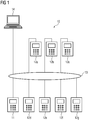
- FIG 1 shows an energy automation system 10 for controlling and monitoring an in Figure 1 for the sake of clarity, electrical power supply network not shown.
- the energy automation system 10 has a first field device 11, which is, for example, an electrical protective device or a process control device.
- IED "Intelligent Electronic Device”
- the term "field device” is intended both for protective devices, I&C devices, measuring devices (RTUs) and others usually under the term IED summarized automation devices for energy automation systems are used.
- the energy automation system 10 further comprises further field devices 12a to 12g.
- the field devices 11 and 12a to 12g have communication devices with interfaces to a physical communication medium in the form of a communication network 13, which can be an Ethernet communication network, for example.
- the communication network 13 can be constructed, for example, in a star or ring topology; the specific structure plays no role in the implementation of the method described below.
- the communication network 13 can be wired or wireless.
- the field devices 11 and 12a to 12g control and / or monitor in Figure 1 Primary components of the electrical power supply network, not shown.
- the field devices 11 and 12a to 12g can also be connected to hierarchically higher-level control and monitoring devices of the energy automation system 10, such as a station monitoring device or a network control center; such connections are in Figure 1 however, not shown for the sake of clarity.
- the field devices 11 and 12a to 12g exchange data telegrams during the operation of the energy automation system 10, which contain information that should be transmitted within the energy automation system as possible in real time (i.e. without a significant delay due to transmission and / or further processing steps).
- the information contained in the data telegrams can be, for example, changes in the status of a primary component of the electrical power supply network monitored or controlled by the respective field device 11 or 12a to 12g.
- a change in state can indicate that a short circuit has occurred on a line section of the electrical power supply network.
- the data telegrams can either contain mere information about the change of state or also include commands to other field devices which are to cause them to open, close or block a circuit breaker, for example.
- the data telegrams transmitted via the communication network 13 can be so-called GOOSE data telegrams or GOOSE messages.
- such GOOSE messages are sent simultaneously from a field device in a so-called multicast or broadcast process to all or some selected receiver field devices.
- the IEC 61850 standard provides for a regular repetition of the GOOSE data telegrams, whereby the repetitions can take place at a higher frequency in the event of critical status changes. This makes it possible to continuously distribute the current status of the primary components monitored by the field devices 11 and 12a to 12g throughout the entire automation system and to disseminate status changes in the automation system under high real-time conditions.
- the communication connections over which the data telegrams are transmitted must be configured with great care, at least when the energy automation system is started up and when changes are made to the energy automation system.
- the term “communication connection” should in particular be understood to mean the respective send and receive settings in the field devices 11 and 12a to 12g, since these send and receive settings are responsible for ensuring that the data telegrams are transmitted correctly to the communication network 13 by the correct recipient group are received within the field devices 11 and 12a to 12g and, after their reception in the respective field device, trigger the desired reactions.
- a data processing device 14 is used to carry out a configuration of the communication connections between the first field device 11 and at least one further field device 12a to 12g Figure 1 is only reproduced by way of example in the form of a laptop which is likewise connected to the communication network 13. Instead of the laptop, such a data processing device 14 can also be formed by other suitable separate data processing devices (eg desktop PCs) or can also be part of one of the field devices 11 or 12a to 12g.
- desktop PCs eg desktop PCs
- Figure 2 a schematic flow diagram of an embodiment of a method for configuring a communication link between the field devices 11 12a to 12g. It should be assumed that the field devices 11, 12a to 12g and the communication network 13 are set up in accordance with the IEC 61850 standard and therefore data telegrams are transmitted for cross-communication between the field devices 11, 12a to 12g in the form of GOOSE messages.
- the application case is to be considered, for example, that a trigger signal generated by the field device 12a is to trigger a GOOSE message which is transmitted to the first field device 11 and there is intended to block a trigger signal generated by the first field device 11 itself.
- a trigger signal generated by the field device 12a is to trigger a GOOSE message which is transmitted to the first field device 11 and there is intended to block a trigger signal generated by the first field device 11 itself.
- Such a scenario is quite common in energy automation systems and is used, for example, when several protective devices detect a fault on one line of the energy supply network, but only the protective device closest to the fault (here the field device 12a) should actually trigger.
- the data processing device 14 performs according to a first step 20 (cf. Figure 2 ) a graphical editor.
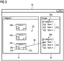
- a graphical editor 30 An embodiment of such a graphical editor 30 is exemplified in FIG Figure 3 played.
- the graphic editor 30 has a first selection area 31 and a second selection area 32.
- the first selection area 31 comprises a graphic representation of functions of the first field device 11 of the energy automation system 10. This representation is shown here only by way of example in the form of a logic diagram 33 with individual logic modules 34a, 34b, 34c.
- the first display area can of course depict more or fewer functions depending on the actual functional scope of the first field device; in Figure 3 only three such functions have been shown for the sake of clarity.
- a logic scheme 33 as described in Figure 3 is also known as the "CFC Editor" and enables graphic representation and linking of individual logic modules.
- Each logic module represents a basic function of the field device 11, which can be linked to other logic modules via inputs, for example inputs 35a and 35b of the logic module 34c, and outputs, for example the output 35c of the logic module 34c.
- inputs for example inputs 35a and 35b of the logic module 34c
- outputs for example the output 35c of the logic module 34c.
- displaying the first selection area 31 in the form of a logic scheme it can also be configured, for example, as a signal routing matrix or as a single-line editor.
- the second selection area 32 of the editor 30 is a graphic representation of the first field device 11 (cf. Figure 1 ) via a physical communication medium in the form of the communication network 13 connected further field devices 12a to 12g and an indication of possible output signals that can be generated by the further field devices during their operation.
- a tree structure shows graphical representations 36a and 36b of two further field devices, each of which includes information 37a and 37b about the possible output signals of these further field devices.
- the second selection area 32 can of course be shown in FIG Figure 3 have further entries, but these have been omitted in the exemplary embodiment shown here for the sake of clarity.
- the second selection area 32 consequently represents an overview of those further field devices 12a to 12g that are associated with the first field device 11 of the energy automation system 10 are connected via the communication network 13.
- the possible output signals of these further field devices are consequently available for the functions of the first field device, so that GOOSE messages can be configured in this regard.
- optional step 21 (cf. Figure 2 ) are carried out, according to which a system description file, which is present anyway to describe the function and structure of the energy automation system 10, is used to determine the further field devices 12a to 12g connected to the first field device 11 and an indication of the output signals which can be generated by them.
- SCD System Description file
- a control device (in.) Which is higher than the field devices 11, 12a to 12g Figure 1 not shown) and / or in one or more of the field devices 11, 12a to 12g itself.
- the other field devices 12a to 12g actually connected to the first field device 11 can also be queried, for example by a data processing device 14 sending a broadcast Message is generated, which includes an identification request to the field devices 11, 12a to 12g receiving this message.
- the field devices 11, 12a to 12g send an identification (for example a unique device number) and an indication of the output signals they can generate to the data processing device 14.
- the Field devices 11, 12a to 12g can be used by the data processing device 14 to generate the second selection area 32, only the responses of the further field devices 12a to 12g connected to the first field device 11 being taken into account.
- the editor 30 is executed by the first field device 11 itself, the two alternatives for generating the second selection window are carried out in a corresponding manner directly by the first field device 11 itself.
- this user selection is recorded in accordance with step 22 and in step 23 in a first parameter set for the first field device 11 and a further parameter set for the further one Field device 14a implemented, these parameter sets include instructions for configuring the communication connection of the first field device 11 and the further field device 12a, which, when the output signal "signal 1" of the further field device 12a is present, sends a GOOSE message from the further field device 12a to the first field device 11 and the triggering of the selected function "function 3" of the first field device 11 when the data telegram is received by the first field device 11.
- all the settings required for sending and receiving this GOOSE message are automatically created both in the first field device 11 and in the further field device 12a, including the creation of a corresponding dataset in the further field device 12a.
- the properties of the GOOSE message are automatically defined. It can either be provided that the GOOSE message is sent from the further field device 12a directly to the first field device 11 using a corresponding recipient address of the first field device 11, or that the GOOSE message is sent as a broadcast or multicast message in the communication network is sent and the first field device is set such that it allows receipt of this GOOSE message.
- an automatic adaptation of a system description file can also be carried out by entering the now configured communication connection there.
- the first parameter set is transmitted to the first field device 11 and the second parameter set to the second field device 12a.
- This can be done, for example, via the communication network 13 or by means of a data carrier.
- the parameter sets are interpreted by the respective field device in such a way that their The respective communication devices ensure that the desired communication connection - that is, the generation of a GOOSE message by the further field device 12a in the case of the present trigger signal (“signal 1”), the receipt of the GOOSE message by the first field device 11 and the activation of the blocking signal "Function 3" of the first field device 11 - is set up.
- the parameter sets can of course also include settings for further communication connections and also for other functions of the respective field devices.
- the described method for configuring field devices means that the system configuration previously required for creating communication connections in conventional energy automation systems is shifted to the device configuration level at the system level and enables a greatly simplified configuration of the cross communication between the individual field devices.
- the user can achieve a high level of benefit with minimal effort and thereby avoids the risk of making incorrect configurations due to incorrect manual settings, which have a negative or even safety-critical impact on the operation of the field devices.
- In-depth knowledge of the regulations relevant for the communication connections e.g. The IEC 61850 standard, its terminology and the elements to be used for configuration are not necessary.
Landscapes
- Engineering & Computer Science (AREA)
- Physics & Mathematics (AREA)
- General Physics & Mathematics (AREA)
- Automation & Control Theory (AREA)
- General Engineering & Computer Science (AREA)
- Manufacturing & Machinery (AREA)
- Quality & Reliability (AREA)
- Power Engineering (AREA)
- Remote Monitoring And Control Of Power-Distribution Networks (AREA)
- Selective Calling Equipment (AREA)
- Mobile Radio Communication Systems (AREA)
Description
Die Erfindung bezieht sich auf ein Verfahren zum Konfigurieren von Kommunikationsverbindungen zwischen Feldgeräten einer Energieautomatisierungsanlage sowie eine Datenverarbeitungseinrichtung, mit der eine solche Konfigurierung durchgeführt werden kann.The invention relates to a method for configuring communication connections between field devices of an energy automation system and a data processing device with which such a configuration can be carried out.
Energieautomatisierungsanlagen dienen zur Automatisierung von elektrischen Energieversorgungsnetzen und umfassen üblicherweise sogenannte Feldgeräte, die in der Nähe von Primärkomponenten des elektrischen Energieversorgungsnetzes angeordnet sind. Solche Primärkomponenten können beispielsweise elektrische Kabel und Leitungen, Transformatoren, Generatoren, Motoren oder Umrichter sein. Üblicherweise nehmen die elektrischen Feldgeräte hierbei Messwerte auf, die den Betriebszustand der jeweiligen Primärkomponenten des elektrischen Energieversorgungsnetzes beschreiben. Diese Messwerte können entweder gespeichert oder an dem jeweiligen Feldgerät übergeordnete Steuer- und Überwachungskomponenten der Energieautomatisierungsanlage weitergeleitet werden. Außerdem können als sogenannte "Schutzgeräte" ausgeführte Feldgeräte dazu eingerichtet sein, anhand spezieller Algorithmen die aufgenommenen Messwerte dahingehend zu überprüfen, ob sie einen zulässigen oder einen unzulässigen Betriebszustand der jeweiligen Primärkomponente des elektrischen Energieversorgungsnetzes kennzeichnen. Im Falle eines unzulässigen Betriebszustandes werden geeignete Maßnahmen ausgelöst (z.B. das Öffnen eines Leistungsschalters), um die Primärkomponente vor Beschädigung oder Personen vor Verletzungen zu schützen. Bei einem unzulässigen Betriebszustand kann es sich beispielsweise um einen Kurzschluss auf einer Leitung des elektrischen Energieversorgungsnetzes handeln.Energy automation systems are used for the automation of electrical energy supply networks and usually comprise so-called field devices which are arranged in the vicinity of primary components of the electrical energy supply network. Such primary components can be, for example, electrical cables and wires, transformers, generators, motors or converters. The electrical field devices usually record measured values that describe the operating state of the respective primary components of the electrical power supply network. These measured values can either be stored or forwarded to the control and monitoring components of the energy automation system which are superordinate to the respective field device. In addition, field devices designed as so-called "protective devices" can be set up to use special algorithms to check the recorded measured values to determine whether they identify an admissible or an inadmissible operating state of the respective primary component of the electrical power supply network. In the event of an impermissible operating state, suitable measures are triggered (eg opening a circuit breaker) to protect the primary component from damage or people from injuries. An inadmissible operating state can be, for example Act short circuit on a line of the electrical power supply network.
Ein Beispiel eines Verfahrens zum Konfigurieren von Feldgeräten einer technischen Anlage in Form einer Kraftwerksanlage ist aus der
Die Feldgeräte einer Energieautomatisierungsanlage sind üblicherweise nicht nur mit hierarchisch übergeordneten Steuer- und Überwachungsgeräten verbunden, sondern weisen auch untereinander Kommunikationsverbindungen zur sogenannten "Querkommunikation" auf, um in kürzest möglicher Zeit, d.h. möglichst in "Echtzeit", Daten und Befehle miteinander austauschen zu können, die eine geeignete Reaktion auf den jeweils erkannten Betriebszustand der jeweiligen Primärkomponente ermöglichen.The field devices of an energy automation system are usually not only connected to hierarchically higher-level control and monitoring devices, but also have communication connections with one another for so-called "cross-communication" in order to achieve the shortest possible time, i.e. to be able to exchange data and commands with one another as possible in "real time", which enable a suitable reaction to the respectively recognized operating state of the respective primary component.
Bei einer solchen Querkommunikation können beispielsweise Informationen über einen erkannten unzulässigen Betriebszustand oder Befehle zum Auslösen eines von dem empfangenden Feldgerät kontrollierten Leistungsschalters (ein sogenanntes "Mitnahmesignal") bzw. zum Blockieren eines von dem empfangenden Feldgerät kontrollierten Leistungsschalters (ein sogenanntes "Blockiersignal" oder "Verriegelungssignal") übermittelt werden.With such cross communication, for example, information about a recognized impermissible operating state or commands for triggering a circuit breaker controlled by the receiving field device (a so-called "carry-along signal") or for blocking a circuit breaker controlled by the receiving field device (a so-called "blocking signal" or "locking signal") ") are transmitted.
In herkömmlichen Energieautomatisierungsanlagen für elektrische Energieversorgungsnetze waren hierzu die einzelnen Feldgeräte mittels analog oder digital arbeitender Ein- bzw. Ausgänge über eine Festverdrahtung miteinander verbunden, das heißt über separat zwischen den einzelnen Feldgeräten verlegte elektrische Leitungen. Dies erforderte einen hohen Verdrahtungsaufwand.In conventional energy automation systems for electrical power supply networks, the individual field devices were connected to one another by means of analog or digital inputs or outputs via fixed wiring, that is to say via electrical lines which were laid separately between the individual field devices. This required a lot of wiring.
Bei jüngeren Energieautomatisierungsanlagen ist man daher dazu übergegangen, die einzelnen Feldgeräte der Energieautomatisierungsanlage an ein gemeinsames Kommunikationsnetz, wie beispielsweise ein Ethernet-Kommunikationsnetz, anzuschließen und die jeweiligen Daten und Befehle zwischen den Feldgeräten in Form von Datentelegrammen auszutauschen. Ein solcher Aufbau ist beispielsweise aus dem die Kommunikation in Energieautomatisierungsanlagen regelnden Standard "IEC 61850" der "International Electrotechnical Commission" bekannt. Die IEC 61850 ist der aktuell und zukünftig maßgebliche Kommunikationsstandard im Bereich der Energieautomatisierung. Gemäß dem Standard werden unter anderem sogenannte "GOOSE-Datentelegramme" (GOOSE = Generic Object Oriented Substation Events) beschrieben, die eine Querkommunikation zwischen den einzelnen Feldgeräten ermöglichen, um besonders schnell und effizient Daten und Befehle direkt zwischen den einzelnen Feldgeräten der Energieautomatisierungsanlage auszutauschen.In the case of more recent energy automation systems, there has therefore been a transition to connecting the individual field devices of the energy automation system to a common communication network, such as an Ethernet communication network, and the respective data and commands between the field devices exchange in the form of data telegrams. Such a structure is known, for example, from the "International Electrotechnical Commission" standard "IEC 61850" regulating communication in energy automation systems. IEC 61850 is the current and future decisive communication standard in the field of energy automation. According to the standard, so-called "GOOSE data telegrams" (GOOSE = Generic Object Oriented Substation Events) are described which enable cross-communication between the individual field devices in order to exchange data and commands directly and particularly quickly and efficiently between the individual field devices of the energy automation system.
Entsprechend der Verlegung und der elektrischen Verschaltung von separaten Festverdrahtungen bei herkömmlichen Energieautomatisierungsanlagen, müssen auch bei der Einrichtung, der Inbetriebsetzung oder Veränderung der einer modernen Energieautomatisierungsanlage, die zur Querkommunikation zwischen den Feldgeräten Datentelegramme versendet, die einzelnen Kommunikationsverbindungen in den jeweiligen Feldgeräten - und ggf. auch einem übergeordneten Leitgerät - eingerichtet bzw. konfiguriert werden. Die Konfigurierung solcher Kommunikationsverbindungen umfasst z.B. die Festlegung von Sendern und Empfängern einzelner Datentelegramme, die Einstellung von für die Kommunikation zu verwendenden Adressen und die Festlegung der Reaktionen des Empfängers auf den Empfang eines bestimmten Datentelegramms.Corresponding to the laying and electrical connection of separate hardwirings in conventional energy automation systems, the individual communication connections in the respective field devices - and possibly also when setting up, commissioning or changing a modern energy automation system that sends data telegrams for cross-communication between the field devices a higher-level control device - can be set up or configured. The configuration of such communication connections includes e.g. the definition of transmitters and receivers of individual data telegrams, the setting of addresses to be used for communication and the determination of the reactions of the recipient to the receipt of a specific data telegram.
Diese Konfigurierung erfolgt heutzutage üblicherweise mittels eines sogenannten Systemkonfigurators. Ein Systemkonfigurator ist ein eigenständiges Softwareprogramm, das es ermöglicht, übergreifend für die Energieautomatisierungsanlage Einstellungen für Datentelegramme, z.B. GOOSE-Nachrichten, in Form von sogenannten "Datasets" zu bündeln. Die in den Datasets festgelegten Einstellungen sollen für die Querkommunikation zwischen den Feldgeräten verwendet werden. In ihnen werden Quelle und Ziel der einzelnen Datentelegramme definiert. Hierzu muss der Benutzer eines Systemkonfigurators auf manuelle Weise viele verschiedene Informationen miteinander verknüpfen und daraus Einstellungen sowohl für die einzelnen Feldgeräte als auch für weitere übergeordnete Leitgeräte der Energieautomatisierungsanlage erzeugen.Nowadays, this configuration is usually carried out using a so-called system configurator. A system configurator is an independent software program that enables settings for data telegrams, such as GOOSE messages, to be bundled in the form of so-called "datasets" for the energy automation system. The one in the datasets The specified settings are to be used for cross-communication between the field devices. The source and destination of the individual data telegrams are defined in them. To do this, the user of a system configurator has to manually link a lot of different information with one another and use it to generate settings for the individual field devices as well as for other higher-level control devices of the energy automation system.
Neben der hohen Anzahl an vom Benutzer der Energieautomatisierungsanlage durchzuführenden Aktionen ist ein wesentlicher Nachteil dieser manuellen Konfigurierung vor allem auch in der Tatsache zu sehen, dass der Benutzer selbst bei vergleichsweise einfachen Anwendungsfällen weitgehende Kenntnisse des für die Kommunikationseinstellungen maßgeblichen Regelwerkes, im Falle von GOOSE-Nachrichten also der IEC 61850, benötigt. Die manuellen Einstellungen sind mit einem hohen Fehlerrisiko verbunden, die nachträgliche Suche nach solchen Fehlern ist sehr aufwändig.In addition to the high number of actions to be carried out by the user of the energy automation system, a major disadvantage of this manual configuration can also be seen in the fact that the user has extensive knowledge of the rules governing the communication settings, even in the case of comparatively simple applications, in the case of GOOSE messages ie the IEC 61850. The manual settings are associated with a high risk of errors, the subsequent search for such errors is very complex.
Der Erfindung liegt daher die Aufgabe zugrunde, ein Verfahren zur Konfigurierung von Kommunikationsverbindungen von Feldgeräten einer Energieautomatisierungsanlage anzugeben, bei dem ein Benutzer der Energieautomatisierungsanlage auch ohne weitgehende Kenntnisse eines für die Kommunikation maßgeblichen Regelwerkes mit hoher Sicherheit gegen Fehleinstellungen Konfigurationen vornehmen kann.The invention is therefore based on the object of specifying a method for configuring communication connections of field devices of an energy automation system, in which a user of the energy automation system can carry out configurations with a high degree of certainty against incorrect settings even without extensive knowledge of a set of rules relevant for communication.
Zur Lösung dieser Aufgabe wird ein Verfahren zum Konfigurieren von Kommunikationsverbindungen zwischen Feldgeräten einer Energieautomatisierungsanlage vorgeschlagen, bei dem ein grafischer Editor mittels einer Datenverarbeitungseinrichtung ausgeführt wird, wobei der Editor einen ersten Anzeigebereich aufweist, wobei der erste Anzeigebereich eine grafische Darstellung von Funktionen eines ersten Feldgerätes der Energieautomatisierungsanlage umfasst; und wobei der Editor weiterhin einen zweiten Anzeigebereich aufweist, wobei der zweite Anzeigebereich eine grafische Darstellung von zumindest einem weiteren Feldgerät der Energieautomatisierungsanlage umfasst, und wobei der zweite Anzeigebereich eine Angabe von solchen Ausgangssignalen, die von dem zumindest einen weiteren Feldgerät während seines Betriebs erzeugt werden können, umfasst; und wobei das zumindest eine weitere Feldgerät mit dem ersten Feldgerät über ein physikalisches Kommunikationsmedium verbunden ist. Es wird eine benutzerseitige Auswahl einerseits eines Ausgangssignals des zumindest einen weiteren Feldgerätes in dem zweiten Anzeigebereich und andererseits eine benutzerseitige Auswahl einer Funktion des ersten Feldgerätes in dem ersten Anzeigebereich erfasst und ein erster Parametersatz für das erste und zumindest ein weiter Parametersatz für das zumindest eine weitere Feldgerät erzeugt, wobei die Parametersätze Anweisungen zur Konfigurierung der Kommunikationsverbindung des ersten und des zumindest einen weiteren Feldgerätes umfassen, wobei die Anweisungen eine Festlegung von Sender und Empfänger eines Datentelegramms, eine Einstellung von für die Kommunikation des Datentelegramms zu verwendenden Adressen und eine Festlegung einer Reaktion des das Datentelegramm empfangenden Feldgerätes auf den Empfang des Datentelegramms umfassen, und und wobei die Anweisungen im Betrieb der Feldgeräte und bei vorliegendem ausgewählten Ausgangssignal des zumindest einen weiteren Feldgerätes das zumindest eine weitere Feldgerät zum Versand eines Datentelegramms an das erste Feldgerät veranlassen und wobei die Anweisungen im Betrieb der Feldgeräte das erste Feldgerät zur Auslösung der ausgewählten Funktion bei Empfang des von dem zumindest einen weiteren Feldgerätes versendeten Datentelegramms veranlassen und wobei die Datentelegramme als GOOSE-Nachrichten gemäß dem Standard IEC 61850 ausgeführt sind.To achieve this object, a method for configuring communication connections between field devices of an energy automation system is proposed, in which a graphical editor is executed by means of a data processing device, the editor having a first display area, the first display area being a graphical representation of functions of a first field device of the energy automation system; and wherein the editor further comprises a second display area, the second display area comprising a graphical representation of at least one further field device of the energy automation system, and the second display area an indication of such output signals that can be generated by the at least one further field device during its operation , includes; and wherein the at least one further field device is connected to the first field device via a physical communication medium. A user-side selection of an output signal of the at least one further field device in the second display area and, on the other hand, a user-side selection of a function of the first field device in the first display area are recorded, and a first parameter set for the first and at least one further parameter set for the at least one further field device generated, the parameter sets include instructions for configuring the communication connection of the first and the at least one further field device, the instructions defining a transmitter and receiver of a data telegram, a setting of addresses to be used for communication of the data telegram and a reaction of the Field device receiving data telegram to receive the data telegram, and and wherein the instructions in the operation of the field devices and in the present selected output signal of the at least one further field advises the at least one additional field device to send a data telegram to the first field device, and the instructions during operation of the field devices cause the first field device to trigger the selected function when the data telegram sent by the at least one further field device is received, and the data telegrams being GOOSE Messages are executed in accordance with the IEC 61850 standard.
Auf diese Weise kann der Benutzer der Energieautomatisierungsanlage ohne technische Schwierigkeiten eine Kommunikationsverbindung zwischen den Feldgeräten einrichten, ohne hierzu weitgehende Kenntnisse des zugrunde liegenden Regelwerkes besitzen zu müssen. Als Ergebnis der in dem Editor durchgeführten Aktionen werden automatisch die für die Umsetzung der Kommunikationsverbindung notwendigen Parametersätze für die beteiligten Feldgeräte erzeugt. Das Erzeugen der benötigten Parametersätze kann folglich in einem gemeinsamen Schritt erfolgen. Der Benutzer der Energieautomatisierungsanlage kann zudem ohne Wechsel zwischen verschiedenen Werkzeugen und direkt auf der Ebene der beteiligten Feldgeräte die Querkommunikation konfigurieren.In this way, the user of the energy automation system can set up a communication link between the field devices without technical difficulties, without having to have extensive knowledge of the underlying set of rules. As a result of the actions performed in the editor, the parameter sets required for the implementation of the communication connection are automatically generated for the field devices involved. The required parameter sets can thus be generated in a common step. The user of the energy automation system can also configure cross communication without changing between different tools and directly at the level of the field devices involved.
Konkret ist dabei vorgesehen, dass die Datentelegramme als GOOSE-Nachrichten gemäß dem Standard IEC 61850 ausgeführt sind.Specifically, the data telegrams are designed as GOOSE messages in accordance with the IEC 61850 standard.
Eine vorteilhafte Ausführungsform des erfindungsgemäßen Verfahrens sieht vor, dass das erste und das zumindest eine weitere Feldgerät Feldgeräte einer Energieautomatisierungsanlage sind, deren Aufbau und Funktion mittels einer Anlagenbeschreibungsdatei beschrieben wird, und die Parametersätze auch zur Anpassung der Anlagenbeschreibungsdatei verwendet werden.An advantageous embodiment of the method according to the invention provides that the first and the at least one further field device are field devices of an energy automation system, the structure and function of which are described by means of a system description file, and the parameter sets are also used to adapt the system description file.
Eine solche Anlagenbeschreibungsdatei kann beispielsweise auf Systemebene in den Feldgeräten der Energieautomatisierungsanlage übergeordneten Leitstellengeräten verwendet werden und dort Feldgeräte-übergreifende Funktionen der Energieautomatisierungsanlage (z.B. die Kommunikation zwischen den Felgeräten) festlegen. Zum konsistenten Betrieb der Energieautomatisierungsanlage müssen Einstellungen in den Parametersätzen und der Anlagenbeschreibungsdatei inhaltlich übereinstimmen. Mit der beschriebenen Ausführungsform werden die Parametersätze außer zur Einstellung der Feldgeräte auch zur automatischen Anpassung der Anlagenbeschreibungsdatei verwendet, so dass die Konsistenz der Einstellungen sichergestellt ist.Such a system description file can be used, for example, at the system level in the field devices of the energy automation system superordinate control center devices and there define functions of the energy automation system spanning field devices (for example the communication between the field devices). Settings must be made in the parameter sets for the consistent operation of the energy automation system and the content of the system description file. With the described embodiment, the parameter sets are used not only for setting the field devices but also for automatically adapting the system description file, so that the consistency of the settings is ensured.
In diesem Zusammenhang kann außerdem vorteilhaft vorgesehen sein, dass die Anlagenbeschreibungsdatei die zu der Energieautomatisierungsanlage gehörenden Feldgeräte angibt und zur Erzeugung des zweiten Anzeigebereichs diejenigen von der Anlagenbeschreibungsdatei umfassten weiteren Feldgeräte ermittelt werden, welche über ein physikalisches Kommunikationsmedium mit dem ersten Feldgerät verbunden sind, und die ermittelten weiteren Feldgeräte in den zweiten Anzeigebereich aufgenommen werden.In this context, it can also be advantageously provided that the system description file specifies the field devices belonging to the energy automation system and, in order to generate the second display area, the other field devices included in the system description file, which are connected to the first field device via a physical communication medium, are determined and the determined additional field devices are included in the second display area.
Auf diese Weise können automatisch durch bloße Kenntnis der gemäß der Anlagenbeschreibungsdatei miteinander über das Kommunikationsmedium in Verbindung stehenden Feldgeräte in dem zweiten Auswahlbereich des Editors die zur Verfügung stehenden Auswahlmöglichkeiten erzeugt werden, ohne dass hierfür weitere manuelle Einstellungen notwendig wären.In this way, simply by knowing the field devices connected to one another via the communication medium in accordance with the system description file, the available selection options can be generated in the second selection area of the editor without further manual settings being necessary for this.
Konkret kann in diesem Zusammenhang vorgesehen sein, dass die Anlagenbeschreibungsdatei eine SCD-Datei (SCD = "Substation Configuration Description") gemäß dem Standard IEC 61850 ist.Specifically, it can be provided in this context that the system description file is an SCD file (SCD = "Substation Configuration Description") in accordance with the IEC 61850 standard.
Alternativ zur Erzeugung des Inhalts des zweiten Anzeigebereichs aus einer Anlagenbeschreibungsdatei kann auch vorgesehen sein, dass zur Erzeugung des zweiten Anzeigebereichs eine Überprüfung durchgeführt wird, welche weiteren Feldgeräte über ein physikalisches Kommunikationsmedium mit dem ersten Feldgerät verbunden sind, und die bei der Überprüfung erkannten weiteren Feldgeräte in den zweiten Anzeigebereich aufgenommen werden.As an alternative to generating the content of the second display area from a system description file, it can also be provided that a A check is carried out to determine which other field devices are connected to the first field device via a physical communication medium, and the further field devices recognized during the check are included in the second display area.
Auf diese Weise werden nur die tatsächlich über das physikalische Kommunikationsmedium mit dem ersten Feldgerät in Kontakt stehenden weiteren Feldgeräte für die Erzeugung des zweiten Auswahlbereiches berücksichtigt.In this way, only the other field devices that are actually in contact with the first field device via the physical communication medium are taken into account for the generation of the second selection area.
Eine weitere vorteilhafte Ausführungsform des erfindungsgemäßen Verfahrens sieht vor, dass die Datenverarbeitungseinrichtung Bestandteil des ersten Feldgerätes ist.Another advantageous embodiment of the method according to the invention provides that the data processing device is part of the first field device.
Auf diese Weise können die benötigten Parametersätze direkt in dem ersten Feldgerät erzeugt werden, das zur Ausführung des Editors über eine von dem Benutzer bedienbare grafische Benutzerschnittstelle verfügen muss. Der Parametersatz für das erste Feldgerät kann direkt im ersten Feldgerät verwendet werden, während der Parametersatz des zumindest einen weiteren Feldgerätes an dieses übertragen werden muss.In this way, the required parameter sets can be generated directly in the first field device, which must have a graphical user interface that can be operated by the user in order to execute the editor. The parameter set for the first field device can be used directly in the first field device, while the parameter set of the at least one further field device must be transmitted to it.
Alternativ dazu kann jedoch auch vorgesehen sein, dass die Datenverarbeitungseinrichtung ein Konfigurationsrechner ist, der zur Ausführung eines Konfigurationsprogramms eingerichtet ist.Alternatively, however, it can also be provided that the data processing device is a configuration computer which is set up to execute a configuration program.
Bei dieser Ausführungsform wird ein Konfigurationsrechner in Form eines PCs oder eines Laptops, auf dem eine Konfigurationssoftware, z.B. das Konfigurationsprogramm "DIGSI" der Siemens AG installiert ist, zur Ausführung des grafischen Editors und zur Ermittlung der Parametersätze verwendet. Üblicherweise wird das Arbeiten an einem solchen Konfigurationsrechner aufgrund von größeren Bildschirmanzeigen und leichter bedienbaren Eingabegeräten (Tastatur, Maus) für den Benutzer komfortabler sein. Die ermittelten Parametersätze müssen in diesem Fall an alle beteiligten Feldgeräte übertragen werden.In this embodiment, a configuration computer in the form of a PC or a laptop, on which a configuration software, e.g. the configuration program "DIGSI" from Siemens AG is installed, used to execute the graphic editor and to determine the parameter sets. Usually, working on such a configuration computer will be more convenient for the user due to larger screen displays and easier-to-use input devices (keyboard, mouse). In this case, the determined parameter sets must be transferred to all field devices involved.
Eine weitere vorteilhafte Ausführungsform sieht ferner vor, dass die Feldgeräte einstellbare Kommunikationseinrichtungen aufweisen und der erste Parametersatz an das erste und der zumindest eine weitere Parametersatz an das zumindest eine weitere Feldgerät übertragen werden und die Feldgeräte ihre jeweiligen Kommunikationseinrichtungen entsprechend der in den Parametersätzen enthaltenen Anweisungen einstellen.A further advantageous embodiment further provides that the field devices have adjustable communication devices and the first parameter set is transmitted to the first and the at least one further parameter set to the at least one further field device and the field devices set their respective communication devices in accordance with the instructions contained in the parameter sets.
Die oben genannte Aufgabe wird auch durch eine Energieautomatisierungsanlage mit konfigurierbaren Feldgeräten, einem physikalischen Kommunikationsmedium zwischen zumindest einigen der Feldgeräte und einer Datenverarbeitungseinrichtung gelöst, wobei die Datenverarbeitungseinrichtung zur Konfigurierung der Kommunikation zwischen den zumindest einigen Feldgeräten unter Durchführung eines Verfahrens gemäß einem der Ansprüche 1 bis 8 eingerichtet ist.The above task is also accomplished by an energy automation system with configurable field devices, a physical one Communication medium between at least some of the field devices and a data processing device solved, wherein the data processing device is configured to configure the communication between the at least some field devices by performing a method according to one of
Die Erfindung soll nachfolgend anhand eines Ausführungsbeispiels näher erläutert werden. Hierzu zeigen
Figur 1- eine schematische Darstellung einer Energieautomatisierungsanlage mit mehreren Feldgeräten;
Figur 2- ein schematisches Ablaufdiagramm eines Verfahrens zur Konfigurierung von Feldgeräten; und
Figur 3- eine schematische Ansicht eines Ausführungsbeispiels eines grafischen Editors zur Konfigurierung von Feldgeräten.
- Figure 1
- a schematic representation of an energy automation system with several field devices;
- Figure 2
- a schematic flow diagram of a method for configuring field devices; and
- Figure 3
- is a schematic view of an embodiment of a graphical editor for configuring field devices.
Die Energieautomatisierungsanlage 10 umfasst ferner weitere Feldgeräte 12a bis 12g. Zum Austausch von Datentelegrammen untereinander weisen die Feldgeräte 11 sowie 12a bis 12g Kommunikationseinrichtungen mit Schnittstellen zu einem physikalischen Kommunikationsmedium in Form eines Kommunikationsnetzes 13 auf, bei dem es sich beispielsweise um ein Ethernet-Kommunikationsnetz handeln kann. Dabei kann das Kommunikationsnetz 13 beispielsweise in einer Stern- oder Ringtopologie aufgebaut sein; der konkrete Aufbau spielt für die Durchführung des im Folgenden beschriebenen Verfahrens keine Rolle. Ebenso kann das Kommunikationsnetz 13 kabelgebunden oder drahtlos aufgebaut sein. Die Feldgeräte 11 sowie 12a bis 12g steuern und/oder überwachen in
Die Feldgeräte 11 sowie 12a bis 12g können ferner auch mit hierarchisch übergeordneten Steuer- und Überwachungsgeräten der Energieautomatisierungsanlage 10 wie beispielsweise einem Stationsüberwachungsgerät oder einer Netzleitstelle verbunden sein; solche Verbindungen sind in
Über das Kommunikationsnetz 13 tauschen die Feldgeräte 11 sowie 12a bis 12g während des Betriebs der Energieautomatisierungsanlage 10 Datentelegramme aus, die Informationen enthalten, die innerhalb der Energieautomatisierungsanlage möglichst in Echtzeit (also ohne deutliche Verzögerung durch Übertragungs- und/oder Weiterverarbeitungsschritte) übermittelt werden sollen.Via the
Bei in den Datentelegrammen enthaltenen Informationen kann es sich beispielsweise um Zustandsänderungen einer von dem jeweiligen Feldgerät 11 bzw. 12a bis 12g überwachten oder gesteuerten Primärkomponente des elektrischen Energieversorgungsnetzes handeln. Beispielsweise kann eine solche Zustandsänderung anzeigen, dass auf einem Leitungsabschnitt des elektrischen Energieversorgungsnetzes ein Kurzschluss aufgetreten ist. Die Datentelegramme können hierbei entweder bloße Informationen über den Zustandswechsel enthalten oder auch Befehle an andere Feldgeräte umfassen, die diese beispielsweise zum Öffnen, Schließen oder Blockieren eines Leistungsschalters veranlassen sollen.The information contained in the data telegrams can be, for example, changes in the status of a primary component of the electrical power supply network monitored or controlled by the
Ist die Automatisierungsanlage gemäß dem Kommunikationsstandard IEC 61850 eingerichtet, so kann es sich bei den über das Kommunikationsnetz 13 übertragenen Datentelegrammen um sogenannte GOOSE-Datentelegramme bzw. GOOSE-Nachrichten handeln. Gemäß dem Standard IEC 61850 werden solche GOOSE-Nachrichten von einem Feldgerät in einem sogenannten Multicast- oder Broadcastverfahren gleichzeitig an alle oder einige ausgewählte Empfängerfeldgeräte versendet. Der Standard IEC 61850 sieht hierbei ein regelmäßiges Wiederholen der GOOSE-Datentelegramme vor, wobei die Wiederholungen bei kritischen Zustandsänderungen in höherer Frequenz erfolgen können. Hierdurch ist es möglich, den Zustand, der von den Feldgeräten 11 sowie 12a bis 12g überwachten Primärkomponenten ständig aktuell in der gesamten Automatisierungsanlage zu verteilen und Zustandsänderungen unter hohen Echtzeitbedingungen in der Automatisierungsanlage zu verbreiten.If the automation system is set up according to the communication standard IEC 61850, the data telegrams transmitted via the
Allerdings besitzen nicht alle möglichen Arten von in den Datentelegrammen enthaltenen Informationen Relevanz für alle übrigen Feldgeräte der Automatisierungsanlage, sodass bestimmten Datentelegrammen eines sendenden Feldgerätes der Automatisierungsanlage jeweils ein ausgewählter Empfängerkreis von weiteren Feldgeräten zugeordnet sein kann.However, not all possible types of information contained in the data telegrams are relevant for all other field devices of the automation system, so that certain data telegrams of a sending field device of the automation system a selected group of receivers from other field devices can be assigned.
Da die korrekte Übertragung der zwischen den Feldgeräten übertragenen Datentelegramme von großer Wichtigkeit für das ordnungsgemäße Funktionieren der Energieautomatisierungsanlage ist, müssen die Kommunikationsverbindungen, über die die Datentelegramme übertragen werden, zumindest bei der Inbetriebsetzung der Energieautomatisierungsanlage sowie bei Änderungen an der Energieautomatisierungsanlage mit großer Sorgfalt konfiguriert werden. Hierbei sollen unter dem Begriff "Kommunikationsverbindung" insbesondere die jeweiligen Sende- und Empfangseinstellungen in den Feldgeräten 11 und 12a bis 12g verstanden werden, da diese Sende- und Empfangseinstellungen dafür zuständig sind, dass die Datentelegramme korrekt in das Kommunikationsnetz 13 übertragen werden, vom richtigen Empfängerkreis innerhalb der Feldgeräte 11 sowie 12a bis 12g empfangen werden und nach ihrem Empfang im jeweiligen Feldgerät die gewünschten Reaktionen veranlassen.Since the correct transmission of the data telegrams transmitted between the field devices is of great importance for the proper functioning of the energy automation system, the communication connections over which the data telegrams are transmitted must be configured with great care, at least when the energy automation system is started up and when changes are made to the energy automation system. Here, the term “communication connection” should in particular be understood to mean the respective send and receive settings in the
Zur Durchführung einer Konfigurierung der Kommunikationsverbindungen zwischen dem ersten Feldgerät 11 und zumindest einem weiteren Feldgerät 12a bis 12g wird eine Datenverarbeitungseinrichtung 14 eingesetzt, die in
Im Folgenden soll unter Hinzunahme der
Um eine solche Kommunikationsverbindung zu konfigurieren, führt die Datenverarbeitungseinrichtung 14 gemäß einem ersten Schritt 20 (vgl.
Der grafische Editor 30 weist einen ersten Auswahlbereich 31 sowie einen zweiten Auswahlbereich 32 auf. Der erste Auswahlbereich 31 umfasst eine grafische Darstellung von Funktionen des ersten Feldgerätes 11 der Energieautomatisierungsanlage 10. Diese Darstellung ist hier lediglich beispielhaft in Form eines Logikschemas 33 mit einzelnen Logikbausteinen 34a, 34b, 34c wiedergegeben. Der erste Anzeigebereich kann selbstverständlich abhängig von dem tatsächlichen Funktionsumfang des ersten Feldgerätes mehr oder weniger Funktionen darstellen; in
Der zweite Auswahlbereich 32 des Editors 30 eine grafische Darstellung von mit dem ersten Feldgerät 11 (vgl.
Der zweite Auswahlbereich 32 stellt folglich eine Übersicht derjenigen weiteren Feldgeräte 12a bis 12g dar, die mit dem ersten Feldgerät 11 der Energieautomatisierungsanlage 10 über das Kommunikationsnetz 13 verbunden sind. Die möglichen Ausgangssignale dieser weiteren Feldgeräte stehen folglich für die Funktionen des ersten Feldgerätes zur Verfügung, so dass diesbezüglich GOOSE-Nachrichten konfiguriert werden können. Zur Erzeugung des zweiten Auswahlbereiches kann beispielsweise der optionale Schritt 21 (vgl.
Alternativ zu der Bestimmung der in dem zweiten Auswahlbereich 32 des Editors 30 darzustellenden weiteren Feldgeräte 12a bis 12g aus der Anlagenbeschreibungsdatei kann auch eine Abfrage der tatsächlich mit dem ersten Feldgerät 11 verbundenen weiteren Feldgeräte 12a bis 12g stattfinden, indem beispielsweise von der Datenverarbeitungseinrichtung 14 eine Broadcast-Nachricht erzeugt wird, die eine Identifizierungsaufforderung an die diese Nachricht empfangenden Feldgeräte 11, 12a bis 12g umfasst. Als Reaktion auf die Identifizierungsaufforderung senden die Feldgeräte 11, 12a bis 12g eine Identifikation (z.B. eine eindeutige Gerätenummer) sowie eine Angabe über die von ihnen erzeugbaren Ausgangssignale an die Datenverarbeitungseinrichtung 14 zurück. Diese Antworten der Feldgeräte 11, 12a bis 12g können von der Datenverarbeitungseinrichtung 14 zur Erzeugung des zweiten Auswahlbereichs 32 genutzt werden, wobei hierzu lediglich die Antworten der mit dem ersten Feldgerät 11 verbundenen weiteren Feldgeräte 12a bis 12g berücksichtigt werden.As an alternative to determining the
Wenn anstelle der Datenverarbeitungseinrichtung 14 der Editor 30 von dem ersten Feldgerät 11 selbst ausgeführt wird, werden die beiden Alternativen zur Erzeugung des zweiten Auswahlfensters in entsprechender Weise direkt von dem ersten Feldgerät 11 selbst durchgeführt.If, instead of the
In einem weiteren Schritt 22 (vgl.
Diese Benutzerauswahl wird gemäß dem Schritt 22 erfasst und gemäß Schritt 23 in einen ersten Parametersatz für das erste Feldgerät 11 und einen weiteren Parametersatz für das weitere Feldgerät 14a umgesetzt, wobei diese Parametersätze Anweisungen zur Konfigurierung der Kommunikationsverbindung des ersten Feldgerätes 11 und des weiteren Feldgerätes 12a umfassen, die bei im Falle eines Vorliegens des Ausgangssignals "Signal 1" des weiteren Feldgerätes 12a einen Versand einer GOOSE-Nachricht von dem weiteren Feldgerät 12a an das erste Feldgerät 11 und die Auslösung der ausgewählten Funktion "Funktion 3" des ersten Feldgerätes 11 bei Empfang des Datentelegramms durch das erste Feldgerät 11 angeben. Hierbei erfolgt ein automatisches Anlegen aller zum Versand und zum Empfang dieser GOOSE-Nachricht notwendigen Einstellungen sowohl in dem ersten Feldgerät 11 als auch in dem weiteren Feldgerät 12a, inklusive der Anlage eines entsprechenden Datasets im weiteren Feldgerät 12a. Außerdem werden die Eigenschaften der GOOSE-Nachricht, wie z.B. Adresseinstellungen und die durch die GOOSE-Nachricht auszulösende Reaktion, automatisch festgelegt. Hierbei kann entweder vorgesehen sein, dass die GOOSE-Nachricht von dem weiteren Feldgerät 12a unter Nutzung einer entsprechenden Empfängeradresse des ersten Feldgerätes 11 direkt an das erste Feldgerät 11 versendet wird, oder dass die GOOSE-Nachricht als Broadcast- bzw. Multicast-Nachricht im Kommunikationsnetz versendet wird und das erste Feldgerät derart eingestellt wird, dass es einen Empfang dieser GOOSE-Nachricht zulässt. Außerdem kann auch eine automatische Anpassung einer Anlagenbeschreibungsdatei vorgenommen werden, indem die nunmehr konfigurierte Kommunikationsverbindung dort eingetragen wird.This user selection is recorded in accordance with
In abschließenden Schritten 24a und 24b werden der erste Parametersatz an das erste Feldgerät 11 und der zweite Parametersatz an das zweite Feldgerät 12a übermittelt. Dies kann z.B. über das Kommunikationsnetz 13 oder mittels eines Datenträgers erfolgen. Die Parametersätze werden von dem jeweiligen Feldgerät derart interpretiert, dass eine Einstellung ihrer jeweiligen Kommunikationseinrichtungen dahingehend erfolgt, dass die gewünschte Kommunikationsverbindung - also das Erzeugen einer GOOSE-Nachricht durch das weitere Feldgerät 12a im Falle des vorliegenden Auslösesignals ("Signal 1"), der Empfang der GOOSE-Nachricht durch das erste Feldgerät 11 und die Aktivierung des Blockiersignals "Funktion 3" des ersten Feldgerätes 11 - eingerichtet wird.In
Neben den Einstellungen bezüglich dieser Kommunikationsverbindung können die Parametersätze natürlich auch Einstellungen zu weiteren Kommunikationsverbindungen und auch zu anderen Funktionen der jeweiligen Feldgeräte umfassen.In addition to the settings relating to this communication connection, the parameter sets can of course also include settings for further communication connections and also for other functions of the respective field devices.
Durch das beschriebene Verfahren zur Konfigurierung von Feldgeräten wird die zur Anlegung von Kommunikationsverbindungen in herkömmlichen Energieautomatisierungsanlagen bisher notwendige Systemkonfiguration auf Systemebene auf die Ebene der Gerätekonfiguration verlagert und ermöglicht eine stark vereinfachte Konfigurierung der Querkommunikation zwischen den einzelnen Feldgeräten. Der Benutzer kann mit einem für ihn minimalen Aufwand einen hohen Nutzen erreichen und vermeidet dabei das Risiko, durch falsche manuelle Einstellungen fehlerhafte Konfigurierungen vorzunehmen, die sich im Betrieb der Feldgeräte negativ oder sogar sicherheitskritisch bemerkbar machen. Eine intensive Kenntnis der für die Kommunikationsverbindungen maßgeblichen Regelwerke, z.B. der Norm IEC 61850, ihrer Fachterminologie und den für die Konfigurierung zu verwendenden Elementen, ist hierbei nicht notwendig.The described method for configuring field devices means that the system configuration previously required for creating communication connections in conventional energy automation systems is shifted to the device configuration level at the system level and enables a greatly simplified configuration of the cross communication between the individual field devices. The user can achieve a high level of benefit with minimal effort and thereby avoids the risk of making incorrect configurations due to incorrect manual settings, which have a negative or even safety-critical impact on the operation of the field devices. In-depth knowledge of the regulations relevant for the communication connections, e.g. The IEC 61850 standard, its terminology and the elements to be used for configuration are not necessary.
Claims (9)
- Method for configuring communication links between field devices (11, 12a - 12g) in a power automation installation (10), in which- a graphical editor (30) is executed using a data processing device (14), wherein- the editor (30) has a first display area (31), wherein the first display area (31) comprises a graphical representation (33) of functions of a first field device (11) in the power automation installation (10); and wherein- the editor (30) furthermore has a second display area (32), wherein the second display area (32) comprises a graphical representation (36a, 36b) of at least one further field device (12a-12g) in the power automation installation (10), and wherein the second display area (32) comprises an indication (37a, 37b) of those output signals which can be produced by the at least one further field device (12a-12g) during the operation thereof; and wherein- the at least one further field device is connected to the first field device (11) by means of a physical communication medium (13);wherein the following further steps are performed in the method:- a user selection of an output signal from the at least one further field device (e.g. 12a) in the second display area (32) and a user selection of a function of the first field device (11) in the first display area (31) are captured;- a first parameter set for the first (11) and at least one further parameter set for the at least one further field device (e.g. 12a) are produced, wherein the parameter sets comprise instructions for configuring the communication link between the first (11) and the at least one further field device (e.g. 12a), wherein the instructions comprise a stipulation of the sender and receiver of a data telegram, a setting for addresses to be used for communicating the data telegram and a stipulation of a reaction by the field device receiving the data telegram to reception of the data telegram, and wherein, during operation of the field devices and when there is a selected output signal available from the at least one further field device (e.g. 12a), the instructions prompt the at least one further field device (e.g. 12a) to send a data telegram to the first field device (11), and wherein, during operation of the field devices, the instructions prompt the first field device (11) to trigger the selected function when the data telegram sent by the at least one further field device is received, and wherein the data telegrams are in the form of GOOSE messages based on the IEC 61850 standard.
- Method according to the preceding claim, characterized in that- the first (11) and the at least one further field device (e.g. 12a) are field devices in a power automation installation (10), the design and function of which are described using an installation description file; and- the parameter sets are also used for customizing the installation description file.
- Method according to Claim 2,
characterized in that- the installation description file indicates the field devices (11, 12a-12g) which belong to the power automation installation (10); and- the second display area is produced by ascertaining those further field devices (12a-12g) which the installation description file comprises which are connected to the first field device (11) by means of a physical communication medium (13) and including the ascertained further field devices (12a-12g) in the second display area (32). - Method according to either of Claims 2 or 3,
characterized in that- the installation description file is an SCD file based on the IEC 61850 standard. - Method according to Claim 1 or 2,
characterized in that- the second display area (32) is produced by performing a check to determine which further field devices (12a-12g) are connected to the first field device (11) by means of a physical communication medium (13) and including the further field devices (12a-12g) which are identified during the check in the second display area (32). - Method according to one of the preceding claims,
characterized in that- the data processing device is part of the first field device (11). - Method according to one of Claims 1 to 6,
characterized in that- the data processing device (14) is a configuration computer which is set up to execute a configuration program. - Method according to one of the preceding claims,
characterized in that- the field devices (11, 12a-12g) have adjustable communication devices; and- the first parameter set is transmitted to the first field device (11) and the at least one further parameter set is transmitted to the at least one further field device (e.g. 12a), and the field devices set their respective communication devices in line with the instructions which the parameter sets contain. - Power automation installation (10) having configurable field devices (11, 12a-12g), a physical communication medium (13) between at least a few of the field devices (11, 12a-12g) and a data processing device (14) which is set up to configure the communication between the at least a few field devices (11, 12a-12g) by performing a method according to one of Claims 1 to 8.
Applications Claiming Priority (1)
| Application Number | Priority Date | Filing Date | Title |
|---|---|---|---|
| PCT/EP2010/060892 WO2012013219A1 (en) | 2010-07-27 | 2010-07-27 | Configuration of the communication links of field devices in a power automation installation |
Publications (2)
| Publication Number | Publication Date |
|---|---|
| EP2598954A1 EP2598954A1 (en) | 2013-06-05 |
| EP2598954B1 true EP2598954B1 (en) | 2020-01-22 |
Family
ID=44064820
Family Applications (1)
| Application Number | Title | Priority Date | Filing Date |
|---|---|---|---|
| EP10739339.9A Active EP2598954B1 (en) | 2010-07-27 | 2010-07-27 | Configuration of the communication links of field devices in a power automation installation |
Country Status (5)
| Country | Link |
|---|---|
| US (1) | US20140067148A1 (en) |
| EP (1) | EP2598954B1 (en) |
| CN (1) | CN103026307B (en) |
| BR (1) | BR112013002068A2 (en) |
| WO (1) | WO2012013219A1 (en) |
Families Citing this family (10)
| Publication number | Priority date | Publication date | Assignee | Title |
|---|---|---|---|---|
| WO2012119648A1 (en) * | 2011-03-09 | 2012-09-13 | Siemens Aktiengesellschaft | Power automation installation and method for operating a power automation installation |
| WO2014091419A1 (en) * | 2012-12-13 | 2014-06-19 | Abb Technology Ltd | A method of configuration for control application in a control system |
| CN104731608B (en) * | 2013-12-23 | 2018-06-15 | 西门子公司 | PLC control methods, control device and PLC |
| US20150294037A1 (en) * | 2014-04-11 | 2015-10-15 | General Electric Company | System and method for automated substation design and configuration |
| DE102014210292A1 (en) * | 2014-05-30 | 2015-12-03 | Rohde & Schwarz Gmbh & Co. Kg | Measuring device, measuring system and method for operating a measuring system with rapid synchronization of settings |
| DE102014216822A1 (en) * | 2014-08-25 | 2016-02-25 | Siemens Aktiengesellschaft | Energy management method, energy management device, switching device for an energy management device and computer software product |
| EP3067768B1 (en) * | 2015-03-11 | 2018-04-25 | Siemens Aktiengesellschaft | Automation device and operator system |
| EP3088976B1 (en) * | 2015-04-28 | 2017-11-29 | Siemens Aktiengesellschaft | Method for operating an automation device and automation device |
| DE102015120731A1 (en) * | 2015-11-30 | 2017-06-01 | Endress+Hauser Process Solutions Ag | Method and system for optimizing the commissioning of at least one of a plurality of field devices in automation technology |
| EP3930130A1 (en) * | 2020-06-26 | 2021-12-29 | Siemens Aktiengesellschaft | Protective device and computer program product, and method for parameterizing a protective device |
Family Cites Families (7)
| Publication number | Priority date | Publication date | Assignee | Title |
|---|---|---|---|---|
| JP2007536634A (en) * | 2004-05-04 | 2007-12-13 | フィッシャー−ローズマウント・システムズ・インコーポレーテッド | Service-oriented architecture for process control systems |
| US8621117B2 (en) * | 2004-11-30 | 2013-12-31 | Abb Research Ltd. | Intelligent configuration system for power distribution feeder reclosers and switches |
| EP1886198B1 (en) * | 2005-06-01 | 2011-01-05 | Siemens Aktiengesellschaft | Parameterization device and method for parameterizing electrical devices |
| DE102006042805A1 (en) * | 2006-09-08 | 2008-03-27 | Endress + Hauser Gmbh + Co. Kg | Method for generating consistent device-specific software components for field devices of automation technology |
| US20080189638A1 (en) * | 2006-10-16 | 2008-08-07 | Invensys Systems, Inc. | Bridging human machine interface technologies in a process automation and information management environment |
| EP2096512A1 (en) * | 2008-02-29 | 2009-09-02 | Siemens Aktiengesellschaft | Method and device for projecting the field devices of a technical array |
| GB2495434B (en) * | 2008-09-29 | 2013-05-22 | Fisher Rosemount Systems Inc | Efficient design and configuration of elements in a process control system |
-
2010
- 2010-07-27 CN CN201080068281.4A patent/CN103026307B/en active Active
- 2010-07-27 EP EP10739339.9A patent/EP2598954B1/en active Active
- 2010-07-27 WO PCT/EP2010/060892 patent/WO2012013219A1/en active Application Filing
- 2010-07-27 US US13/812,665 patent/US20140067148A1/en not_active Abandoned
- 2010-07-27 BR BR112013002068A patent/BR112013002068A2/en not_active IP Right Cessation
Non-Patent Citations (1)
| Title |
|---|
| None * |
Also Published As
| Publication number | Publication date |
|---|---|
| EP2598954A1 (en) | 2013-06-05 |
| RU2013108664A (en) | 2014-09-10 |
| CN103026307B (en) | 2016-05-04 |
| BR112013002068A2 (en) | 2016-05-24 |
| US20140067148A1 (en) | 2014-03-06 |
| CN103026307A (en) | 2013-04-03 |
| WO2012013219A1 (en) | 2012-02-02 |
Similar Documents
| Publication | Publication Date | Title |
|---|---|---|
| EP2598954B1 (en) | Configuration of the communication links of field devices in a power automation installation | |
| EP1096348B1 (en) | Integration of a field guidance device in a plant guidance system | |
| WO2008145170A1 (en) | Method for configuring an automation system | |
| EP1749340A1 (en) | Solar inverter and photovoltaic installation comprising several solar inverters | |
| EP1427086B2 (en) | Electrical apparatus and method for operating it | |
| EP2988183B1 (en) | System for observing and/or controlling a plant | |
| EP2517328A1 (en) | Expanded power automation system | |
| DE102016124348A1 (en) | System and microservice for monitoring a process automation system | |
| EP3070556B1 (en) | Method, computing device, user unit and system for parameterizing an electrical apparatus | |
| EP2684335B1 (en) | Power automation installation and method for operating a power automation installation | |
| EP2940926A1 (en) | Method for configuring a communication device within an industrial automation system and distribution unit for a configuration server of an industrial communication network | |
| EP1296207B1 (en) | HMI apparatus and method for operating a technical installation, automation system with HMI apparatus and computer program product with program for carrying out the method in a HMI apparatus or in an automation system | |
| EP2274874B1 (en) | Examination of a communication connection between field devices | |
| EP1690390B1 (en) | Method for transmitting data via a data bus and system and gateway for carrying out said method | |
| EP2883294B1 (en) | Method for the computer-aided control of an electrical energy distribution network consisting of a plurality of network nodes | |
| DE102010042199A1 (en) | Method for operating field bus interface (FI), involves performing polling of demand-related diagnostic information over field bus by field bus interface, and detecting queried diagnostic information by field bus interface | |
| EP1787471A1 (en) | Method and automation system for monitoring at least one facility component of a technical facility | |
| EP1929382B1 (en) | Parameterisation device and method or parameterising electrical devices | |
| EP1709497A1 (en) | Device for the transmission of field device data by means of a radio link | |
| EP1096349A1 (en) | Configuration of a plant guidance sytem | |
| EP4262155A1 (en) | Device and method for connecting a field device to a communication system | |
| DE102010056078A1 (en) | Common communication system for several external automation systems of an automation network | |
| DE10335429A1 (en) | Field unit log generation method for use in an automation system whereby field unit data are requested from an automation system processing unit by a monitoring application running on a user data processing system and recorded | |
| DE102004051834A1 (en) | Testing unit for programmable electrical installations, especially building installations with an electronic control bus, has a gateway to the installation via which the data of individual network members or units can be accessed | |
| EP2028575B1 (en) | Method for reading and/or writing characteristics or parameters of an installation device connected to a bus system |
Legal Events
| Date | Code | Title | Description |
|---|---|---|---|
| PUAI | Public reference made under article 153(3) epc to a published international application that has entered the european phase |
Free format text: ORIGINAL CODE: 0009012 |
|
| 17P | Request for examination filed |
Effective date: 20130121 |
|
| AK | Designated contracting states |
Kind code of ref document: A1 Designated state(s): AL AT BE BG CH CY CZ DE DK EE ES FI FR GB GR HR HU IE IS IT LI LT LU LV MC MK MT NL NO PL PT RO SE SI SK SM TR |
|
| DAX | Request for extension of the european patent (deleted) | ||
| 17Q | First examination report despatched |
Effective date: 20140606 |
|
| RAP1 | Party data changed (applicant data changed or rights of an application transferred) |
Owner name: SIEMENS AKTIENGESELLSCHAFT |
|
| RIC1 | Information provided on ipc code assigned before grant |
Ipc: G05B 19/042 20060101AFI20190724BHEP Ipc: H02J 4/00 20060101ALI20190724BHEP Ipc: G05B 19/418 20060101ALI20190724BHEP |
|
| GRAP | Despatch of communication of intention to grant a patent |
Free format text: ORIGINAL CODE: EPIDOSNIGR1 |
|
| STAA | Information on the status of an ep patent application or granted ep patent |
Free format text: STATUS: GRANT OF PATENT IS INTENDED |
|
| INTG | Intention to grant announced |
Effective date: 20190912 |
|
| GRAS | Grant fee paid |
Free format text: ORIGINAL CODE: EPIDOSNIGR3 |
|
| GRAA | (expected) grant |
Free format text: ORIGINAL CODE: 0009210 |
|
| STAA | Information on the status of an ep patent application or granted ep patent |
Free format text: STATUS: THE PATENT HAS BEEN GRANTED |
|
| AK | Designated contracting states |
Kind code of ref document: B1 Designated state(s): AL AT BE BG CH CY CZ DE DK EE ES FI FR GB GR HR HU IE IS IT LI LT LU LV MC MK MT NL NO PL PT RO SE SI SK SM TR |
|
| REG | Reference to a national code |
Ref country code: GB Ref legal event code: FG4D Free format text: NOT ENGLISH |
|
| REG | Reference to a national code |
Ref country code: CH Ref legal event code: EP |
|
| REG | Reference to a national code |
Ref country code: AT Ref legal event code: REF Ref document number: 1227308 Country of ref document: AT Kind code of ref document: T Effective date: 20200215 |
|
| REG | Reference to a national code |
Ref country code: IE Ref legal event code: FG4D Free format text: LANGUAGE OF EP DOCUMENT: GERMAN |
|
| REG | Reference to a national code |
Ref country code: DE Ref legal event code: R096 Ref document number: 502010016466 Country of ref document: DE |
|
| REG | Reference to a national code |
Ref country code: NL Ref legal event code: MP Effective date: 20200122 |
|
| REG | Reference to a national code |
Ref country code: LT Ref legal event code: MG4D |
|
| PG25 | Lapsed in a contracting state [announced via postgrant information from national office to epo] |
Ref country code: NO Free format text: LAPSE BECAUSE OF FAILURE TO SUBMIT A TRANSLATION OF THE DESCRIPTION OR TO PAY THE FEE WITHIN THE PRESCRIBED TIME-LIMIT Effective date: 20200422 Ref country code: NL Free format text: LAPSE BECAUSE OF FAILURE TO SUBMIT A TRANSLATION OF THE DESCRIPTION OR TO PAY THE FEE WITHIN THE PRESCRIBED TIME-LIMIT Effective date: 20200122 Ref country code: FI Free format text: LAPSE BECAUSE OF FAILURE TO SUBMIT A TRANSLATION OF THE DESCRIPTION OR TO PAY THE FEE WITHIN THE PRESCRIBED TIME-LIMIT Effective date: 20200122 Ref country code: PT Free format text: LAPSE BECAUSE OF FAILURE TO SUBMIT A TRANSLATION OF THE DESCRIPTION OR TO PAY THE FEE WITHIN THE PRESCRIBED TIME-LIMIT Effective date: 20200614 |
|
| PG25 | Lapsed in a contracting state [announced via postgrant information from national office to epo] |
Ref country code: IS Free format text: LAPSE BECAUSE OF FAILURE TO SUBMIT A TRANSLATION OF THE DESCRIPTION OR TO PAY THE FEE WITHIN THE PRESCRIBED TIME-LIMIT Effective date: 20200522 Ref country code: GR Free format text: LAPSE BECAUSE OF FAILURE TO SUBMIT A TRANSLATION OF THE DESCRIPTION OR TO PAY THE FEE WITHIN THE PRESCRIBED TIME-LIMIT Effective date: 20200423 Ref country code: LV Free format text: LAPSE BECAUSE OF FAILURE TO SUBMIT A TRANSLATION OF THE DESCRIPTION OR TO PAY THE FEE WITHIN THE PRESCRIBED TIME-LIMIT Effective date: 20200122 Ref country code: HR Free format text: LAPSE BECAUSE OF FAILURE TO SUBMIT A TRANSLATION OF THE DESCRIPTION OR TO PAY THE FEE WITHIN THE PRESCRIBED TIME-LIMIT Effective date: 20200122 Ref country code: SE Free format text: LAPSE BECAUSE OF FAILURE TO SUBMIT A TRANSLATION OF THE DESCRIPTION OR TO PAY THE FEE WITHIN THE PRESCRIBED TIME-LIMIT Effective date: 20200122 Ref country code: BG Free format text: LAPSE BECAUSE OF FAILURE TO SUBMIT A TRANSLATION OF THE DESCRIPTION OR TO PAY THE FEE WITHIN THE PRESCRIBED TIME-LIMIT Effective date: 20200422 |
|
| REG | Reference to a national code |
Ref country code: DE Ref legal event code: R097 Ref document number: 502010016466 Country of ref document: DE |
|
| PG25 | Lapsed in a contracting state [announced via postgrant information from national office to epo] |
Ref country code: DK Free format text: LAPSE BECAUSE OF FAILURE TO SUBMIT A TRANSLATION OF THE DESCRIPTION OR TO PAY THE FEE WITHIN THE PRESCRIBED TIME-LIMIT Effective date: 20200122 Ref country code: EE Free format text: LAPSE BECAUSE OF FAILURE TO SUBMIT A TRANSLATION OF THE DESCRIPTION OR TO PAY THE FEE WITHIN THE PRESCRIBED TIME-LIMIT Effective date: 20200122 Ref country code: LT Free format text: LAPSE BECAUSE OF FAILURE TO SUBMIT A TRANSLATION OF THE DESCRIPTION OR TO PAY THE FEE WITHIN THE PRESCRIBED TIME-LIMIT Effective date: 20200122 Ref country code: ES Free format text: LAPSE BECAUSE OF FAILURE TO SUBMIT A TRANSLATION OF THE DESCRIPTION OR TO PAY THE FEE WITHIN THE PRESCRIBED TIME-LIMIT Effective date: 20200122 Ref country code: CZ Free format text: LAPSE BECAUSE OF FAILURE TO SUBMIT A TRANSLATION OF THE DESCRIPTION OR TO PAY THE FEE WITHIN THE PRESCRIBED TIME-LIMIT Effective date: 20200122 Ref country code: RO Free format text: LAPSE BECAUSE OF FAILURE TO SUBMIT A TRANSLATION OF THE DESCRIPTION OR TO PAY THE FEE WITHIN THE PRESCRIBED TIME-LIMIT Effective date: 20200122 Ref country code: SK Free format text: LAPSE BECAUSE OF FAILURE TO SUBMIT A TRANSLATION OF THE DESCRIPTION OR TO PAY THE FEE WITHIN THE PRESCRIBED TIME-LIMIT Effective date: 20200122 Ref country code: SM Free format text: LAPSE BECAUSE OF FAILURE TO SUBMIT A TRANSLATION OF THE DESCRIPTION OR TO PAY THE FEE WITHIN THE PRESCRIBED TIME-LIMIT Effective date: 20200122 |
|
| PLBE | No opposition filed within time limit |
Free format text: ORIGINAL CODE: 0009261 |
|
| STAA | Information on the status of an ep patent application or granted ep patent |
Free format text: STATUS: NO OPPOSITION FILED WITHIN TIME LIMIT |
|
| 26N | No opposition filed |
Effective date: 20201023 |
|
| PG25 | Lapsed in a contracting state [announced via postgrant information from national office to epo] |
Ref country code: SI Free format text: LAPSE BECAUSE OF FAILURE TO SUBMIT A TRANSLATION OF THE DESCRIPTION OR TO PAY THE FEE WITHIN THE PRESCRIBED TIME-LIMIT Effective date: 20200122 Ref country code: MC Free format text: LAPSE BECAUSE OF FAILURE TO SUBMIT A TRANSLATION OF THE DESCRIPTION OR TO PAY THE FEE WITHIN THE PRESCRIBED TIME-LIMIT Effective date: 20200122 Ref country code: PL Free format text: LAPSE BECAUSE OF FAILURE TO SUBMIT A TRANSLATION OF THE DESCRIPTION OR TO PAY THE FEE WITHIN THE PRESCRIBED TIME-LIMIT Effective date: 20200122 |
|
| REG | Reference to a national code |
Ref country code: CH Ref legal event code: PL |
|
| REG | Reference to a national code |
Ref country code: BE Ref legal event code: MM Effective date: 20200731 |
|
| PG25 | Lapsed in a contracting state [announced via postgrant information from national office to epo] |
Ref country code: CH Free format text: LAPSE BECAUSE OF NON-PAYMENT OF DUE FEES Effective date: 20200731 Ref country code: LI Free format text: LAPSE BECAUSE OF NON-PAYMENT OF DUE FEES Effective date: 20200731 Ref country code: LU Free format text: LAPSE BECAUSE OF NON-PAYMENT OF DUE FEES Effective date: 20200727 |
|
| PG25 | Lapsed in a contracting state [announced via postgrant information from national office to epo] |
Ref country code: BE Free format text: LAPSE BECAUSE OF NON-PAYMENT OF DUE FEES Effective date: 20200731 |
|
| PG25 | Lapsed in a contracting state [announced via postgrant information from national office to epo] |
Ref country code: IE Free format text: LAPSE BECAUSE OF NON-PAYMENT OF DUE FEES Effective date: 20200727 |
|
| REG | Reference to a national code |
Ref country code: AT Ref legal event code: MM01 Ref document number: 1227308 Country of ref document: AT Kind code of ref document: T Effective date: 20200727 |
|
| PG25 | Lapsed in a contracting state [announced via postgrant information from national office to epo] |
Ref country code: AT Free format text: LAPSE BECAUSE OF NON-PAYMENT OF DUE FEES Effective date: 20200727 |
|
| PG25 | Lapsed in a contracting state [announced via postgrant information from national office to epo] |
Ref country code: TR Free format text: LAPSE BECAUSE OF FAILURE TO SUBMIT A TRANSLATION OF THE DESCRIPTION OR TO PAY THE FEE WITHIN THE PRESCRIBED TIME-LIMIT Effective date: 20200122 Ref country code: MT Free format text: LAPSE BECAUSE OF FAILURE TO SUBMIT A TRANSLATION OF THE DESCRIPTION OR TO PAY THE FEE WITHIN THE PRESCRIBED TIME-LIMIT Effective date: 20200122 Ref country code: CY Free format text: LAPSE BECAUSE OF FAILURE TO SUBMIT A TRANSLATION OF THE DESCRIPTION OR TO PAY THE FEE WITHIN THE PRESCRIBED TIME-LIMIT Effective date: 20200122 |
|
| PG25 | Lapsed in a contracting state [announced via postgrant information from national office to epo] |
Ref country code: MK Free format text: LAPSE BECAUSE OF FAILURE TO SUBMIT A TRANSLATION OF THE DESCRIPTION OR TO PAY THE FEE WITHIN THE PRESCRIBED TIME-LIMIT Effective date: 20200122 Ref country code: AL Free format text: LAPSE BECAUSE OF FAILURE TO SUBMIT A TRANSLATION OF THE DESCRIPTION OR TO PAY THE FEE WITHIN THE PRESCRIBED TIME-LIMIT Effective date: 20200122 |
|
| PGFP | Annual fee paid to national office [announced via postgrant information from national office to epo] |
Ref country code: IT Payment date: 20230725 Year of fee payment: 14 Ref country code: GB Payment date: 20230807 Year of fee payment: 14 |
|
| PGFP | Annual fee paid to national office [announced via postgrant information from national office to epo] |
Ref country code: FR Payment date: 20230720 Year of fee payment: 14 Ref country code: DE Payment date: 20230918 Year of fee payment: 14 |