EP2582052A1 - LDPC decoding of composite codewords and sub-codewords - Google Patents
LDPC decoding of composite codewords and sub-codewords Download PDFInfo
- Publication number
- EP2582052A1 EP2582052A1 EP12184422.9A EP12184422A EP2582052A1 EP 2582052 A1 EP2582052 A1 EP 2582052A1 EP 12184422 A EP12184422 A EP 12184422A EP 2582052 A1 EP2582052 A1 EP 2582052A1
- Authority
- EP
- European Patent Office
- Prior art keywords
- codeword
- sub
- data
- encoded sub
- encoded
- Prior art date
- Legal status (The legal status is an assumption and is not a legal conclusion. Google has not performed a legal analysis and makes no representation as to the accuracy of the status listed.)
- Withdrawn
Links
Images


Classifications
-
- H—ELECTRICITY
- H03—ELECTRONIC CIRCUITRY
- H03M—CODING; DECODING; CODE CONVERSION IN GENERAL
- H03M13/00—Coding, decoding or code conversion, for error detection or error correction; Coding theory basic assumptions; Coding bounds; Error probability evaluation methods; Channel models; Simulation or testing of codes
- H03M13/03—Error detection or forward error correction by redundancy in data representation, i.e. code words containing more digits than the source words
- H03M13/05—Error detection or forward error correction by redundancy in data representation, i.e. code words containing more digits than the source words using block codes, i.e. a predetermined number of check bits joined to a predetermined number of information bits
- H03M13/13—Linear codes
- H03M13/15—Cyclic codes, i.e. cyclic shifts of codewords produce other codewords, e.g. codes defined by a generator polynomial, Bose-Chaudhuri-Hocquenghem [BCH] codes
-
- H—ELECTRICITY
- H03—ELECTRONIC CIRCUITRY
- H03M—CODING; DECODING; CODE CONVERSION IN GENERAL
- H03M13/00—Coding, decoding or code conversion, for error detection or error correction; Coding theory basic assumptions; Coding bounds; Error probability evaluation methods; Channel models; Simulation or testing of codes
- H03M13/03—Error detection or forward error correction by redundancy in data representation, i.e. code words containing more digits than the source words
- H03M13/05—Error detection or forward error correction by redundancy in data representation, i.e. code words containing more digits than the source words using block codes, i.e. a predetermined number of check bits joined to a predetermined number of information bits
- H03M13/11—Error detection or forward error correction by redundancy in data representation, i.e. code words containing more digits than the source words using block codes, i.e. a predetermined number of check bits joined to a predetermined number of information bits using multiple parity bits
- H03M13/1102—Codes on graphs and decoding on graphs, e.g. low-density parity check [LDPC] codes
-
- G—PHYSICS
- G11—INFORMATION STORAGE
- G11B—INFORMATION STORAGE BASED ON RELATIVE MOVEMENT BETWEEN RECORD CARRIER AND TRANSDUCER
- G11B20/00—Signal processing not specific to the method of recording or reproducing; Circuits therefor
- G11B20/10—Digital recording or reproducing
- G11B20/18—Error detection or correction; Testing, e.g. of drop-outs
- G11B20/1833—Error detection or correction; Testing, e.g. of drop-outs by adding special lists or symbols to the coded information
-
- H—ELECTRICITY
- H03—ELECTRONIC CIRCUITRY
- H03M—CODING; DECODING; CODE CONVERSION IN GENERAL
- H03M13/00—Coding, decoding or code conversion, for error detection or error correction; Coding theory basic assumptions; Coding bounds; Error probability evaluation methods; Channel models; Simulation or testing of codes
- H03M13/03—Error detection or forward error correction by redundancy in data representation, i.e. code words containing more digits than the source words
- H03M13/05—Error detection or forward error correction by redundancy in data representation, i.e. code words containing more digits than the source words using block codes, i.e. a predetermined number of check bits joined to a predetermined number of information bits
- H03M13/11—Error detection or forward error correction by redundancy in data representation, i.e. code words containing more digits than the source words using block codes, i.e. a predetermined number of check bits joined to a predetermined number of information bits using multiple parity bits
-
- H—ELECTRICITY
- H03—ELECTRONIC CIRCUITRY
- H03M—CODING; DECODING; CODE CONVERSION IN GENERAL
- H03M13/00—Coding, decoding or code conversion, for error detection or error correction; Coding theory basic assumptions; Coding bounds; Error probability evaluation methods; Channel models; Simulation or testing of codes
- H03M13/29—Coding, decoding or code conversion, for error detection or error correction; Coding theory basic assumptions; Coding bounds; Error probability evaluation methods; Channel models; Simulation or testing of codes combining two or more codes or code structures, e.g. product codes, generalised product codes, concatenated codes, inner and outer codes
- H03M13/2942—Coding, decoding or code conversion, for error detection or error correction; Coding theory basic assumptions; Coding bounds; Error probability evaluation methods; Channel models; Simulation or testing of codes combining two or more codes or code structures, e.g. product codes, generalised product codes, concatenated codes, inner and outer codes wherein a block of parity bits is computed only from combined information bits or only from parity bits, e.g. a second block of parity bits is computed from a first block of parity bits obtained by systematic encoding of a block of information bits, or a block of parity bits is obtained by an XOR combination of sub-blocks of information bits
-
- H—ELECTRICITY
- H03—ELECTRONIC CIRCUITRY
- H03M—CODING; DECODING; CODE CONVERSION IN GENERAL
- H03M13/00—Coding, decoding or code conversion, for error detection or error correction; Coding theory basic assumptions; Coding bounds; Error probability evaluation methods; Channel models; Simulation or testing of codes
- H03M13/37—Decoding methods or techniques, not specific to the particular type of coding provided for in groups H03M13/03 - H03M13/35
- H03M13/3761—Decoding methods or techniques, not specific to the particular type of coding provided for in groups H03M13/03 - H03M13/35 using code combining, i.e. using combining of codeword portions which may have been transmitted separately, e.g. Digital Fountain codes, Raptor codes or Luby Transform [LT] codes
-
- H—ELECTRICITY
- H03—ELECTRONIC CIRCUITRY
- H03M—CODING; DECODING; CODE CONVERSION IN GENERAL
- H03M13/00—Coding, decoding or code conversion, for error detection or error correction; Coding theory basic assumptions; Coding bounds; Error probability evaluation methods; Channel models; Simulation or testing of codes
- H03M13/63—Joint error correction and other techniques
- H03M13/6331—Error control coding in combination with equalisation
-
- H—ELECTRICITY
- H03—ELECTRONIC CIRCUITRY
- H03M—CODING; DECODING; CODE CONVERSION IN GENERAL
- H03M13/00—Coding, decoding or code conversion, for error detection or error correction; Coding theory basic assumptions; Coding bounds; Error probability evaluation methods; Channel models; Simulation or testing of codes
- H03M13/63—Joint error correction and other techniques
- H03M13/6343—Error control coding in combination with techniques for partial response channels, e.g. recording
-
- H—ELECTRICITY
- H03—ELECTRONIC CIRCUITRY
- H03M—CODING; DECODING; CODE CONVERSION IN GENERAL
- H03M13/00—Coding, decoding or code conversion, for error detection or error correction; Coding theory basic assumptions; Coding bounds; Error probability evaluation methods; Channel models; Simulation or testing of codes
- H03M13/65—Purpose and implementation aspects
- H03M13/6502—Reduction of hardware complexity or efficient processing
-
- G—PHYSICS
- G11—INFORMATION STORAGE
- G11B—INFORMATION STORAGE BASED ON RELATIVE MOVEMENT BETWEEN RECORD CARRIER AND TRANSDUCER
- G11B20/00—Signal processing not specific to the method of recording or reproducing; Circuits therefor
- G11B20/10—Digital recording or reproducing
- G11B20/18—Error detection or correction; Testing, e.g. of drop-outs
- G11B20/1833—Error detection or correction; Testing, e.g. of drop-outs by adding special lists or symbols to the coded information
- G11B2020/185—Error detection or correction; Testing, e.g. of drop-outs by adding special lists or symbols to the coded information using an low density parity check [LDPC] code
-
- G—PHYSICS
- G11—INFORMATION STORAGE
- G11B—INFORMATION STORAGE BASED ON RELATIVE MOVEMENT BETWEEN RECORD CARRIER AND TRANSDUCER
- G11B2220/00—Record carriers by type
- G11B2220/20—Disc-shaped record carriers
- G11B2220/25—Disc-shaped record carriers characterised in that the disc is based on a specific recording technology
- G11B2220/2508—Magnetic discs
- G11B2220/2516—Hard disks
Definitions
- the present inventions are related to systems and methods for data processing, and more particularly to systems and methods for data decoding.
- Various storage systems include data processing circuitry implemented with a data decoding circuit.
- the data decoding circuit operates on a very large codeword that includes a number of parity bits. It is an advantage to use increasingly large codewords to achieve increased data processing performance.
- large codewords require large and complex data decoding circuits.
- Such large and complex data decoding circuits require significant die area and power.
- One approach to dealing with this situation is to make a very large codeword out of a number of smaller codewords that are concatenated together. Such smaller codewords allow for reducing the size and power required by the data decoding circuit, but come with a corresponding reduction in processing performance.
- a data processing system as set out in claim 1.
- a storage device as set out in claim 14, the storage device comprising:a storage medium; a head assembly disposed in relation to the storage medium and operable to provide a sensed signal corresponding to information on the storage medium; a read channel circuit including: an analog to digital converter circuit operable to sample an analog signal derived from the sensed signal to yield a series of digital samples; an equalizer circuit operable to equalize the digital samples to yield a data set; a data detector circuit operable to apply a data detection algorithm to the data set to yield a detected output, wherein the data set includes at least a first encoded sub-codeword and a composite sub-codeword; a low density parity check data decoder circuit operable to apply a data decode algorithm to the encoded sub-codeword to yield a first decode
- Various embodiments of the present invention provide data processing systems that include a data detector circuit, a data decoder circuit, and a processing circuit.
- the data detector circuit is operable to apply a data detection algorithm to a data set to yield a detected output.
- the data set includes at least a first encoded sub-codeword and a composite sub-codeword.
- the data decoder circuit is operable to apply a data decode algorithm to the encoded sub-codeword to yield a first decoded output, and to apply the data decode algorithm to the composite sub-codeword to yield a second decoded output.
- the processing circuit is operable to: reconstitute a second encoded sub-codeword from a combination of data including the first encoded sub-codeword and the composite sub-codeword; and correct an error in one of the first encoded sub-codeword and the second encoded sub-codeword based at least in part on a combination of the first encoded sub-codeword, the second encoded sub-codeword, and the composite sub-codeword.
- the data processing system is implemented as part of a storage device or a receiving device.
- the storage device is a disk based storage device.
- the storage device is a solid state storage device.
- the data processing system is implemented as part of an integrated circuit.
- the data detection algorithm is a maximum a posteriori data detection algorithm.
- the data detection algorithm is a Viterbi detection algorithm.
- the data decode algorithm is a low density parity check algorithm.
- the composite codeword is a mathematical combination of at least the first encoded sub-codeword and the second encoded sub-codeword.
- the composite codeword is a mod 2 combination of at least the first encoded sub-codeword and the second encoded sub-codeword.
- reconstituting the second encoded sub-codeword from the combination of data including the first encoded sub-codeword and the composite sub-codeword includes reversing the mathematical combination of at least the first encoded sub-codeword and the second encoded sub-codeword.
- correcting the error in one of the first encoded sub-codeword and the second encoded sub-codeword based at least in part on a combination of the first encoded sub-codeword, the second encoded sub-codeword, and the composite sub-codeword includes modifying an element of one of the first encoded sub-codeword and the second encoded sub-codeword such that the mathematical combination of at least the first encoded sub-codeword and the second encoded sub-codeword yields a correct mathematical relationship.
- the data decoder circuit includes: a first decode circuit operable to apply the data decode algorithm to the encoded sub-codeword to yield the first decoded output, and a second decode circuit operable to apply the data decode algorithm to the composite sub-codeword to yield the second decoded output.
- the data decoder circuit includes a decode circuit that is operable to apply the data decode algorithm to the encoded sub-codeword to yield the first decoded output during a first time period, and apply the data decode algorithm to the composite sub-codeword to yield the second decoded output during a second time period.
- a method for data processing as set out in claim 12.
- Other embodiments of the present invention provide methods for data processing.
- the methods include receiving a data set that includes at least a first encoded sub-codeword and a composite sub-codeword.
- a data detection algorithm is performed by a data detector circuit on the data set to yield a detected output.
- a data decode algorithm is performed on a second data set derived from the detected output to yield a first decoded output corresponding to the first encoded sub-codeword, and the data decode algorithm is performed on a third data set derived from the detected output to yield a second decoded output corresponding to the composite sub-codeword.
- a second encoded sub-codeword is reconstituted from a combination of data including the second decoded output and the first decoded output, and an error in one of the first decoded output and the second decoded output is corrected based at least in part on a combination of the first encoded sub-codeword, the second encoded sub-codeword, and the composite sub-codeword.
- the composite codeword is a mathematical combination of at least the first encoded sub-codeword and the second encoded sub-codeword.
- reconstituting the second encoded sub-codeword from the combination of data including the second decoded output and the first decoded output includes reversing the mathematical combination of at least the first encoded sub-codeword and the second encoded sub-codeword.
- correcting the error in one of the first decoded output and the second decoded output based at least in part on the combination of the first encoded sub-codeword, the second encoded sub-codeword, and the composite sub-codeword includes modifying an element of one of the first encoded sub-codeword and the second encoded sub-codeword such that the mathematical combination of at least the first encoded sub-codeword and the second encoded sub-codeword yields a correct mathematical relationship.
- Various embodiments of the present invention provide low density parity check encoding systems.
- Such encoding systems include: a low density parity check encoder circuit, and a combining circuit.
- the low density parity check encoder circuit is operable to encode a first data set to yield a first low density parity check encoded sub-codeword, and to encode a second data set to yield a second low density parity check encoded sub-codeword.
- the combining circuit is operable to: generate a composite low density parity check sub-codeword by mathematically combining at least the first low density parity check encoded sub-codeword and the second low density parity check encoded sub-codeword; and combine at least the first low density parity check encoded sub-codeword and the composite low density parity check sub-codeword into an overall codeword.
- generating the composite low density parity check sub-codeword includes performing a mod 2 mathematical process on a bit by bit basis of the first low density parity check encoded sub-codeword and the second low density parity check encoded sub-codeword to yield the composite low density parity check sub-codeword.
- mathematically combining at least the first low density parity check encoded sub-codeword and the second low density parity check encoded sub-codeword to yields a valid low density parity check codeword
- the composite low density parity check sub-codeword, the first low density parity check encoded sub-codeword, and the second low density parity check encoded sub-codeword are all decodable using the same low density parity check decoding algorithm.
- Fig. 1 shows a data processing circuit including a shared parity data decoding circuit in accordance with one or more embodiments of the present invention
- Fig. 2 graphically depicts a process for generating a shared parity codeword that may be used in relation to embodiments of the present invention
- Fig. 3 shows a disk based storage device including a read channel having shared parity data decoding circuitry in accordance with one or more embodiments of the present invention
- Fig. 4 shows a solid state storage device including a flash access controller having shared parity data decoding circuitry in accordance with one or more embodiments of the present invention
- Fig. 5 shows a data transmission system including a receiver having shared parity data decoding circuitry in accordance with some embodiments of the present invention
- Fig. 6 is a flow diagram showing method for shared parity codeword processing in accordance with various embodiments of the present invention.
- Fig. 7 depicts a shared parity codeword encoding circuit in accordance with some embodiments of the present invention.
- Fig. 8 is a flow diagram showing method for encoding shared parity codewords in accordance with one or more embodiments of the present invention.
- the present inventions are related to systems and methods for data processing, and more particularly to systems and methods for data decoding.
- Various embodiments of the present invention provide systems and methods for data processing. Such systems and methods rely on an overall codeword that shares parity between a number of sub-codewords. Such an approach allows for enhanced data processing performance where the error correction power of the overall codeword is greater than any one sub-codeword, while allowing for reduced circuit size and power.
- shared parity codewords are created by aggregating a number of sub-codewords, and encoding one of the number of sub-codewords to include parity that represents processing across multiple sub-codewords.
- the sub-codeword incorporating parity from across the sub-codewords may be used to regenerate the otherwise non-converging sub-codeword.
- two or more sub-code-words may be processed by a common data decoder circuit in a time sharing approach that further reduces circuit size.
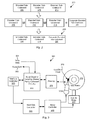
- a data processing circuit 100 that includes a shared parity data decoding circuit 170 that is operable to decode shared parity codewords in accordance with one or more embodiments of the present invention.
- Data processing circuit 100 includes an analog front end circuit 110 that receives an analog signal 105.
- Analog front end circuit 110 processes analog signal 105 and provides a processed analog signal 112 to an analog to digital converter circuit 114.
- Analog front end circuit 110 may include, but is not limited to, an analog filter and an amplifier circuit as are known in the art. Based upon the disclosure provided herein, one of ordinary skill in the art will recognize a variety of circuitry that may be included as part of analog front end circuit 110.
- analog signal 105 is derived from a read/write head assembly (not shown) that is disposed in relation to a storage medium (not shown). In other cases, analog signal 105 is derived from a receiver circuit (not shown) that is operable to receive a signal from a transmission medium (not shown).
- the transmission medium may be wired or wireless.
- Analog to digital converter circuit 114 converts processed analog signal 112 into a corresponding series of digital samples 116.
- Analog to digital converter circuit 114 may be any circuit known in the art that is capable of producing digital samples corresponding to an analog input signal. Based upon the disclosure provided herein, one of ordinary skill in the art will recognize a variety of analog to digital converter circuits that may be used in relation to different embodiments of the present invention.
- Digital samples 116 are provided to an equalizer circuit 120.
- Equalizer circuit 120 applies an equalization algorithm to digital samples 116 to yield an equalized output 125.
- equalizer circuit 120 is a digital finite impulse response filter circuit as are known in the art.
- equalizer 120 includes sufficient memory to maintain one or more codewords until a data detector circuit 130 is available for processing. It may be possible that equalized output 125 may be received directly from a storage device in, for example, a solid state storage system. In such cases, analog front end circuit 110, analog to digital converter circuit 114 and equalizer circuit 120 may be eliminated where the data is received as a digital data input.
- Data detector circuit 130 is operable to apply a data detection algorithm to a received codeword or data set, and in some cases data detector circuit 130 can process two or more codewords in parallel.
- data detector circuit 130 is a Viterbi algorithm data detector circuit as are known in the art.
- data detector circuit 130 is a maximum a posteriori data detector circuit as are known in the art.
- the general phrases "Viterbi data detection algorithm” or "Viterbi algorithm data detector circuit” are used in their broadest sense to mean any Viterbi detection algorithm or Viterbi algorithm detector circuit or variations thereof including, but not limited to, bi-direction Viterbi detection algorithm or bi-direction Viterbi algorithm detector circuit.
- maximum a posteriori data detection algorithm or “maximum a posteriori data detector circuit” are used in their broadest sense to mean any maximum a posteriori detection algorithm or detector circuit or variations thereof including, but not limited to, simplified maximum a posteriori data detection algorithm and a max-log maximum a posteriori data detection algorithm, or corresponding detector circuits. Based upon the disclosure provided herein, one of ordinary skill in the art will recognize a variety of data detector circuits that may be used in relation to different embodiments of the present invention. Data detector circuit 130 is started based upon availability of a data set from equalizer circuit 120 or from a central memory circuit 150.
- Detector output 196 includes soft data.
- soft data is used in its broadest sense to mean reliability data with each instance of the reliability data indicating a likelihood that a corresponding bit position or group of bit positions has been correctly detected.
- the soft data or reliability data is log likelihood ratio data as is known in the art.
- Detected output 196 is provided to a local interleaver circuit 142.
- Local interleaver circuit 142 is operable to shuffle sub-portions (i.e., local chunks) of the data set included as detected output and provides an interleaved codeword 146 that is stored to central memory circuit 150.
- Interleaver circuit 142 may be any circuit known in the art that is capable of shuffling data sets to yield a re-arranged data set.
- Interleaved codeword 146 is stored to central memory circuit 150.
- Interleaved codeword 146 is comprised of a number of encoded sub-codewords designed to reduce the complexity of a downstream data decoder circuit while maintaining reasonable processing ability. An example of such a codeword comprised of encoded sub-codewords is discussed in relation to Fig. 2 .
- FIG. 2 a graphical depiction 200 of a process for generating a shared parity codeword that may be used in relation to embodiments of the present invention.
- Graphical depiction 200 shows a 4Kb codeword formed of a number of encoded sub-codewords 205, 210, 215. It should be noted that the codeword is merely an example, and that a codeword greater than or less than 4Kb may be used and the codeword may be broken into more or fewer than the three shown encoded sub-codewords.
- the encoded sub-codewords are encoded using low density parity check (LDPC) encoding as is known in the art.
- LDPC low density parity check
- Encoded sub-codewords 205, 210, 215 are each constructed by encoding a portion of user data such that each of sub-codewords include parity bits calculated during the encoding process that are calculated based upon the portion of user data represented by the respective sub-codeword.
- the encoding may not limit to this simple example (H1 and H2), but rather can be anything which can construct different correction power low density parity check codes as component codewords.
- encoded sub-codeword 205, encoded sub-codeword 210 and encoded sub-codeword 215 are mathematically combined to yield a composite encoded sub-codeword 220.
- the mathematical combination is a mod 2 operation.
- encoded sub-codeword 205 is combined on an element by element basis using a mod 2 process to yield an interim codeword.
- the interim codeword is then combined on an element by element basis with encoded sub-codeword 215 using a mod 2 process to yield composite encoded sub-codeword 220.
- combining two or more encoded sub-codewords in such a way yields a valid encoded codeword that incorporates parity related to information from more than one encoded sub-codeword.
- the encoded sub-codewords are combined to yield an overall codeword 250 where encoded sub-codeword 215 is replaced by composite encoded sub-codeword 220.
- Overall codeword 250 is then transferred to a storage medium or other transfer medium.
- Overall codeword 250 has the advantage that it may be processed on a sub-codeword basis, but because it includes composite encoded sub-codeword 220 with parity representing information from a number of encoded sub-codewords, increased processing performance is achievable when compared with encoded sub-codewords 205, 210, 215 being processed separately.
- a previously stored interleaved codeword 146 is accessed from central memory circuit 150 as a stored codeword 186 and globally interleaved by a global interleaver/de-interleaver circuit 184.
- Global interleaver/De-interleaver circuit 184 may be any circuit known in the art that is capable of globally rearranging codewords.
- Global interleaver/De-interleaver circuit 184 provides a decoder input 152. As described more fully below, decoder input 152 includes a number of sub-codewords that each include parity with at least one of the sub-codewords including parity that incorporates information from multiple sub-codewords.
- Each of the sub-codewords is provided to a respective one of a subset decoder circuit 162, a subset decoder circuit 164 and a subset decoder circuit 166 incorporated within shared parity data decoding circuit 170.
- Each of subset decoder circuit 162, subset decoder circuit 164 and subset decoder circuit 166 is operable to apply a data decode algorithm to the respective sub-codeword.
- Subset decoder circuit 162 provides a sub-decoded output 163; subset decoder circuit 164 provides a sub-decoded output 165; and subset decoder circuit 166 provides a sub-decoded output 167.
- the data decode algorithm is a low density parity check algorithm as are known in the art. Based upon the disclosure provided herein, one of ordinary skill in the art will recognize other decode algorithms that may be used in relation to different embodiments of the present invention. It should be noted that while shared parity data decoding circuit 170 is shown with three separate subset decoder circuits 162, 164, 166, it is not required to have physically distinct subset decoder circuits. Rather, tie sharing can be used within a smaller number of decoder circuits to simplify circuit design and further reduce circuit area.
- a single subset decoder circuit may be employed that: (1) processes encoded sub-codeword 205 by performing a partial codeword check to variable node update or variable node to check node during a first time slot, (3) processes encoded sub-codeword 210 by performing a partial codeword check to variable node update or variable node to check node during a second time slot, and (3) processes composite encoded sub-codeword 220 by performing a partial codeword check to variable node update or variable node to check node during a third time slot, and so on.
- Each of subset decoder circuits 162, 164, 166 operates on a smaller codeword (e.g., one of encoded sub-codeword 205, encoded sub-codeword 210 or composite encoded sub-codeword 220) than it would be operating on if the respective circuit processed a unified codeword including all of the encoded sub-codewords. Because of this, the aggregate size and power requirements of subset decoder circuits 162, 164, 166 is less than what would be required if a unified codeword including all of the sub-codewords was processed by a single data decoding circuit. It should be noted that while Fig. 1 shows three subset decoder circuits, that more than or fewer than three subset decoder circuits may be used in relation to different embodiments of the present invention.
- subset decoder circuit 162 receives encoded sub-codeword 205
- subset decoder circuit 164 receives encoded sub-codeword 210
- subset decoder circuit 166 receives composite encoded sub-codeword 220.
- each of encoded sub-codeword 205, encoded sub-codeword 210, and composite encoded sub-codeword 220 includes noise introduced from various sources and represented as E1 for encoded sub-codeword 205, E2 for encoded sub-codeword 210, and E3 for composite encoded sub-codeword 220.
- Each of subset decoder circuits 162, 164, 166 applies an LDPC decoding algorithm to the received encoded sub-codeword to yield sub-decoded output 163, sub-decoded output 165, and sub-decoded output 167, respectively.
- Sub-decoded output 163, sub-decoded output 165, and sub-decoded output 167 are provided to a soft data processing circuit 175 included as part of shared parity data decoding circuit 170.
- Soft data processing circuit 175 is operable to assemble the various sub-decoded outputs and to determine whether the respective sub-decoded outputs converged (i.e., the resulting sub-decoded output matches the originally written data set as indicated by the lack of parity errors). Where all of the sub-decoded outputs converged, soft data processing circuit 175 assembles the sub-decoded outputs into an output codeword 172.
- Output codeword 172 is provided to a de-interleaver circuit 180.
- De-interleaver circuit 180 rearranges the data to reverse both the global and local interleaving applied to the data to yield a de-interleaved output 182.
- De-interleaved output 182 is provided to a hard decision output circuit 190.
- Hard decision output circuit 190 is operable to re-order data sets that may complete out of order back into their original order. The originally ordered data sets are then provided as a hard decision output 192.
- soft data processing circuit 175 uses the knowledge from other sub-decoded outputs to correct any remaining errors in a given sub-decoded output. For this processing, soft data processing circuit 175 may set the soft data for the converged encoded sub-codeword to high reliability values. Such high reliability values will be used to help other encoded sub-codeword decoding and speed up the convergence of other encoded sub-codewords.
- encoded sub-codeword 205 and encoded sub-codeword 210 can be properly decoded yielding sub-decoded output 163 and sub-decoded output 165 that converge, but composite sub-codeword 220 cannot be properly decoded such that sub-decoded output 167 does not converge
- the process for generating composite sub-codeword 220 discussed above in relation to Fig. 2 may be reversed to generate a corrected encoded sub-codeword 215.
- Subset decoder circuit 166 can then decode the following information: encoded subcodeword 215 + E ⁇ 3 To recover the original encoded sub-codeword 215 that is provided as sub-decoded output 167 to soft data processing circuit 175 where, if sub-decoded output 167 converged, it can be combined with the other converged sub-decoded outputs to yield output codeword 172.
- soft data processing circuit 175 provides the respective portions of a given sub-decode output back to a corresponding subset decoder circuit for additional processing where another local iteration is allowed. Where another local iteration is not allowed, soft data processing circuit 175 writes the sub-decoded outputs as a decoded output 154 back to central memory circuit 150 where they are stored awaiting another global iteration through data detector circuit 130 and shared parity data decoding circuit 170. Prior to storage of decoded output 154 to central memory circuit 150, decoded output 154 is globally de-interleaved to yield a globally de-interleaved output 188 that is stored to central memory circuit 150.
- the global de-interleaving reverses the global interleaving earlier applied to stored codeword 186 to yield decoder input 152.
- a previously stored de-interleaved output 188 is accessed from central memory circuit 150 and locally de-interleaved by a de-interleaver circuit 144.
- De-interleaver circuit 144 re-arranges decoder output 148 to reverse the shuffling originally performed by interleaver circuit 142.
- a resulting de-interleaved output 197 is provided to data detector circuit 130 where it is used to guide subsequent detection of a corresponding data set receive as equalized output 125.
- the aforementioned processing by soft data processing circuit 175 may be performed on the soft data (i.e., log-likelihood ration (LLR) information) derived from data detector circuit 130.
- LLR log-likelihood ration
- Disk based storage system 300 may be, for example, a hard disk drive.
- Disk based storage system 300 also includes a preamplifier 370, an interface controller 320, a hard disk controller 366, a motor controller 368, a spindle motor 372, a disk platter 378, and a read/write head assembly 376.
- Interface controller 320 controls addressing and timing of data to/from disk platter 378.
- the data on disk platter 378 consists of groups of magnetic signals that may be detected by read/write head assembly 376 when the assembly is properly positioned over disk platter 378.
- disk platter 378 includes magnetic signals recorded in accordance with either a longitudinal or a perpendicular recording scheme.
- read/write head assembly 376 is accurately positioned by motor controller 368 over a desired data track on disk platter 378.
- Motor controller 368 both positions read/write head assembly 376 in relation to disk platter 378 and drives spindle motor 372 by moving read/write head assembly to the proper data track on disk platter 378 under the direction of hard disk controller 366.
- Spindle motor 372 spins disk platter 378 at a determined spin rate (RPMs).
- RPMs spin rate
- This minute analog signal is transferred from read/write head assembly 376 to read channel circuit 310 via preamplifier 370.
- Preamplifier 370 is operable to amplify the minute analog signals accessed from disk platter 378.
- read channel circuit 310 decodes and digitizes the received analog signal to recreate the information originally written to disk platter 378.
- This data is provided as read data 303 to a receiving circuit.
- a write operation is substantially the opposite of the preceding read operation with write data 301 being provided to read channel circuit 310. This data is then encoded and written to disk platter 378.
- data may be encoded prior to a write operation.
- the data encoding may be done such that a data set is encoded into multiple sub-codewords with parity in one or more of the sub-codewords being shared across a number of sub-codewords.
- Such encoding may be done using a circuit similar to that discussed below in relation to Fig. 7 , and/or may perform the encoding using a method similar to that discussed below in relation to Fig. 8 .
- Data read back from disk platter 378 may be decoded using a number of subset decoder circuits each operating on a respective sub-codeword.
- One or more of the sub-codewords may include parity that extends across multiple sub-codewords.
- Such sub-codeword decoding may be done using a circuit similar to that discussed above in relation to Fig. 1 , and/or may be done similar to the method discussed below in relation to Fig. 6 .
- storage system may utilize SATA, SAS or other storage technologies known in the art.
- storage system 300 may be integrated into a larger storage system such as, for example, a RAID (redundant array of inexpensive disks or redundant array of independent disks) based storage system.
- RAID redundant array of inexpensive disks or redundant array of independent disks
- various functions or blocks of storage system 400 may be implemented in either software or firmware, while other functions or blocks are implemented in hardware.
- Solid state storage device 400 includes a solid state memory circuit 440 that includes a number of memory cells.
- solid state memory circuit 440 includes a number of FLASH memory cells as are known in the art.
- Flash access controller 430 includes sub-codeword encoding circuitry operable to encode an overall codeword having a number of encoded sub-codewords with at least one of the encoded sub-codewords incorporating parity information from across two or more encoded sub-codewords.
- Such encoding circuitry may be implemented similar to that discussed below in relation to Fig.
- flash access controller 430 includes sub-codeword decoding circuitry operable to decode an overall codeword having a number of encoded sub-codewords with at least one of the encoded sub-codewords incorporating parity information from across two or more encoded sub-codewords.
- decoding circuitry may be implemented similar to that discussed above in relation to Fig. 1 and/or may operate similar to that discussed below in relation to Fig. 6 .
- Decoded data is provided from flash access controller 430 to an input buffer circuit 410 where it may be accessed by a host (not shown).
- data to be stored to solid state memory 440 is received from a host that writes the data to n output buffer circuit 420 that in turn provides the information to flash access controller 430.
- Data transmission system 500 includes a transmitter 510 that is operable to transmit encoded information via a transfer medium 530 as is known in the art.
- the encoded data is received from transfer medium 530 by receiver 520.
- Transceiver 520 incorporates sub-codeword decoding and encoding circuitry. While processing received data, received data is converted from an analog signal to a series of corresponding digital samples, and the digital samples are equalized to yield an equalized output. The equalized output is then provided to a data processing circuit including both a data detector circuit and a data decoder circuit.
- Transfer medium 530 may be any transfer medium known in the art including, but not limited to, a wireless medium, an optical medium, or a wired medium. Based upon the disclosure provided herein, one of ordinary skill in the art will recognize a variety of transfer mediums that may be used in relation to different embodiments of the present invention. Data may be encoded by transceiver 520 for transmission to another receiver circuit (not shown).
- data may be encoded prior to a transmission operation by transceiver 520.
- the data encoding may be done such that a data set is encoded into multiple sub-codewords with parity in one or more of the sub-codewords being shared across a number of sub-codewords.
- Such encoding may be done using a circuit similar to that discussed below in relation to Fig. 7 , and/or may perform the encoding using a method similar to that discussed below in relation to Fig. 8 .
- Data received from transfer medium 530 may be decoded using a number of subset decoder circuits each operating on a respective sub-codeword.
- One or more of the sub-codewords may include parity that extends across multiple sub-codewords.
- Such sub-codeword decoding may be done using a circuit similar to that discussed above in relation to Fig. 1 , and/or may be done similar to the method discussed below in relation to Fig. 6 .
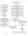
- a flow diagram 600 shows a method for shared parity codeword processing in accordance with various embodiments of the present invention.
- an analog input is received (block 605).
- the analog input may be derived from, for example, a storage medium or a data transmission channel. Based upon the disclosure provided herein, one of ordinary skill in the art will recognize a variety of sources of the analog input.
- the analog input is converted to a series of digital samples (block 610). This conversion may be done using an analog to digital converter circuit or system as are known in the art. Of note, any circuit known in the art that is capable of converting an analog signal into a series of digital values representing the received analog signal may be used.
- the resulting digital samples are equalized to yield an equalized output (block 615).
- the equalization is done using a digital finite impulse response circuit as are known in the art. Based upon the disclosure provided herein, one of ordinary skill in the art will recognize a variety of equalizer circuits that may be used in place of such a digital finite impulse response circuit to perform equalization in accordance with different embodiments of the present invention.
- the equalized output represents an overall codeword comprised of a number of encoded sub-codewords and at least one composite encoded sub-codeword similar to those discussed above in relation to Fig. 2 .
- the input may be received as a digital input. In such cases, the processes of blocks 605, 601, 615 may be eliminated.
- a data detection algorithm is applied to the equalized output guided by a data set derived from a decoded output where available (e.g., the second and later iterations through the data detector circuit and the data decoder circuit) from a central memory circuit to yield a detected output (block 625).
- data detection algorithm is a Viterbi algorithm as are known in the art.
- the data detection algorithm is a maximum a posteriori data detector circuit as are known in the art.
- a signal derived from the detected output (e.g., a locally interleaved version of the detected output) is stored to the central memory to await processing by a data decoder circuit (block 630).
- a data decoder circuit is available (block 640). Where the data decoder circuit is available (block 640) a previously stored derivative of a detected output is accessed from the central memory (block 645). The accessed data set is disaggregated into one or more sub-codewords and one or more composite sub-codewords (block 650). This process may include, using the example of Fig. 2 , separating overall codeword 250 into its component parts: encoded sub-codeword 205, encoded sub-codeword 210, and composite encoded sub-codeword 220.
- a data decoding algorithm is performed on each of the respective sub-codeword(s) and composite encoded sub-codeword(s) to yield corresponding decoded outputs (block 655).
- the data decode algorithm is a low density parity check algorithm as are known in the art.
- the original sub-codewords are reconstituted by reversing the mathematic process applied to the original sub-codeword(s) and composite sub-codeword(s) using decoded outputs (block 660).
- the mathematic process for creating the composite sub-codeword is that described above in relation to Fig.
- L 205 is soft data from a decoded output corresponding to encoded sub-codeword 205
- L 210 is soft data from a decoded output corresponding to encoded sub-codeword 210
- L 220 is soft data from a decoded output corresponding to composite encoded sub-codeword 220:
- L 215 ⁇ j L 205 j + L 210 j + L 220 j + L 205 j ⁇ L 210 j ⁇ L 220 j 1 + L 205 j ⁇ L 210 j + L 205 j ⁇ L 220 j + L 215 j ⁇ L 220 j , where j is the j-th bit of encoded sub-codeword 205, encoded sub-codeword 210, encoded sub-codeword 215, and composite encoded sub-codeword 220; and L ' 215 is the soft data corresponding to the reconstituted encoded
- each of the decoded outputs converged (i.e., whether the decode algorithm applied to each of the sub-codeword(s) and composite sub-codeword(s) converged)(block 665). Where all of the decoded outputs converged (block 665), the hard decision data associated with the decoded outputs is assembled together and provided as a data output (block 680). Otherwise, where all of the decoded outputs did not converge (block 665), additional error correction is applied using the sub-codeword(s), composite sub-codeword(s), and reconstituted sub-codeword(s) to correct any errors remaining in one or more otherwise non-converged sub-codeword(s)(block 670).
- the error correction utilizes the equations corresponding to the mathematical process originally applied to generate the composite sub-codeword.
- Shared parity codeword encoding circuit 700 includes a sub-codeword encoder circuit 710 that receives a data input 705.
- Data input 705 is provided from a host (not shown) that is writing data to a storage medium or transferring data via a transfer medium.
- Data input 705 is separated by sub-codeword encoder circuit 710 into portions, and sub-codeword encoder circuit 710 applies a data encoding algorithm to the respective portions to yield a number of encode sub-codewords 715.
- the data encoding algorithm is a low density parity check encoding algorithm as are known in the art.
- the encoding algorithm adds parity information to the encoded sub-codeword based upon the respective portion of data input 705.
- Encoded sub-codewords 715 are provided to a sub-codeword combining circuit 720 where two or more encoded sub-codewords 715 are mathematically combined to yield a composite encoded sub-codeword.
- Sub-codeword combining circuit 720 assembles the encoded sub-codewords 715 with the composite encoded sub-codeword replacing one of the encoded sub-codewords to yield an overall codeword 725.
- the mathematical generation of the composite encoded sub-codeword may use a mod 2 combination of multiple encoded sub codewords to yield the composite encoded sub-codeword, and the subsequent combining of encoded sub-codewords and the composite encoded sub-codeword maybe done similar to that described above in relation to Fig. 2 .
- Overall codeword 725 is provided to a combined codeword writing circuit 730 that performs any remaining operations in preparation for sending a codeword 735 to a storage medium or a receiving device.
- a flow diagram 800 shows a method for encoding shared parity codewords in accordance with one or more embodiments of the present invention.
- a data input is received (block 805).
- the data input includes user bits and may be received, for example, from a host.
- a number of the user bits are collected for inclusion in a sub-codeword (block 810). In some cases, the number of bits is pre-defined. In other cases, the number of bits is programmable. It is determined whether enough user bits have been received to form a sub-codeword (block 815). Where an insufficient number of user bits have been collected (block 815), the processes of blocks 805-815 are repeated.
- the collected user bits are encoded to yield an encoded sub-codeword (block 820).
- the data encoding is a low density parity check encoding as are known in the art.
- the encoding algorithm adds parity information to the collected user bits to yield an encoded sub-codeword.
- the encoded sub-codewords are combined with the composite sub-codeword to yield an overall codeword (block 850).
- the combining process includes replacing one of the encoded sub-codewords with the composite sub-codeword.
- the mathematical generation of the composite encoded sub-codeword, and the subsequent combining of encoded sub-codewords and the composite encoded sub-codeword maybe done similar to that described above in relation to Fig. 2 .
- Such integrated circuits may include all of the functions of a given block, system or circuit, or only a subset of the block, system or circuit. Further, elements of the blocks, systems or circuits may be implemented across multiple integrated circuits. Such integrated circuits may be any type of integrated circuit known in the art including, but are not limited to, a monolithic integrated circuit, a flip chip integrated circuit, a multichip module integrated circuit, and/or a mixed signal integrated circuit. It should also be noted that various functions of the blocks, systems or circuits discussed herein may be implemented in either software or firmware. In some such cases, the entire system, block or circuit may be implemented using its software or firmware equivalent. In other cases, the one part of a given system, block or circuit may be implemented in software or firmware, while other parts are implemented in hardware.
Abstract
Description
- The present inventions are related to systems and methods for data processing, and more particularly to systems and methods for data decoding.
- Various storage systems include data processing circuitry implemented with a data decoding circuit. In some cases, the data decoding circuit operates on a very large codeword that includes a number of parity bits. It is an advantage to use increasingly large codewords to achieve increased data processing performance. However, such large codewords require large and complex data decoding circuits. Such large and complex data decoding circuits require significant die area and power. One approach to dealing with this situation is to make a very large codeword out of a number of smaller codewords that are concatenated together. Such smaller codewords allow for reducing the size and power required by the data decoding circuit, but come with a corresponding reduction in processing performance.
- Hence, for at least the aforementioned reasons, there exists a need in the art for advanced systems and methods for data processing.
- The present inventions are related to systems and methods for data processing, and more particularly to systems and methods for data decoding. According to a first aspect of the invention, there is provided a data processing system as set out in claim 1. According to another aspect of the invention, there is provided a storage device as set out in claim 14, the storage device comprising:a storage medium; a head assembly disposed in relation to the storage medium and operable to provide a sensed signal corresponding to information on the storage medium; a read channel circuit including: an analog to digital converter circuit operable to sample an analog signal derived from the sensed signal to yield a series of digital samples; an equalizer circuit operable to equalize the digital samples to yield a data set; a data detector circuit operable to apply a data detection algorithm to the data set to yield a detected output, wherein the data set includes at least a first encoded sub-codeword and a composite sub-codeword; a low density parity check data decoder circuit operable to apply a data decode algorithm to the encoded sub-codeword to yield a first decoded output, and to apply the data decode algorithm to the composite sub-codeword to yield a second decoded output; and a processing circuit operable to: reconstitute a second encoded sub-codeword from a combination of data including the first encoded sub-codeword and the composite sub-codeword; and correct an error in one of the first encoded sub-codeword and the second encoded sub-codeword based at least in part on a combination of the first encoded sub-codeword, the second encoded sub-codeword, and the composite sub-codeword.
- Various embodiments of the present invention provide data processing systems that include a data detector circuit, a data decoder circuit, and a processing circuit. The data detector circuit is operable to apply a data detection algorithm to a data set to yield a detected output. The data set includes at least a first encoded sub-codeword and a composite sub-codeword. The data decoder circuit is operable to apply a data decode algorithm to the encoded sub-codeword to yield a first decoded output, and to apply the data decode algorithm to the composite sub-codeword to yield a second decoded output. The processing circuit is operable to: reconstitute a second encoded sub-codeword from a combination of data including the first encoded sub-codeword and the composite sub-codeword; and correct an error in one of the first encoded sub-codeword and the second encoded sub-codeword based at least in part on a combination of the first encoded sub-codeword, the second encoded sub-codeword, and the composite sub-codeword.
- In some instances of the aforementioned embodiments, the data processing system is implemented as part of a storage device or a receiving device. In some cases, the storage device is a disk based storage device. In other cases, the storage device is a solid state storage device. In various instances of the aforementioned embodiments, the data processing system is implemented as part of an integrated circuit. In one or more instances of the aforementioned embodiments the data detection algorithm is a maximum a posteriori data detection algorithm. In other instances, the data detection algorithm is a Viterbi detection algorithm. In some instances of the aforementioned embodiments, the data decode algorithm is a low density parity check algorithm.
- In some instances of the aforementioned embodiments, the composite codeword is a mathematical combination of at least the first encoded sub-codeword and the second encoded sub-codeword. In particular instances of the aforementioned embodiments, the composite codeword is a mod 2 combination of at least the first encoded sub-codeword and the second encoded sub-codeword. In some cases, reconstituting the second encoded sub-codeword from the combination of data including the first encoded sub-codeword and the composite sub-codeword includes reversing the mathematical combination of at least the first encoded sub-codeword and the second encoded sub-codeword. In particular cases, correcting the error in one of the first encoded sub-codeword and the second encoded sub-codeword based at least in part on a combination of the first encoded sub-codeword, the second encoded sub-codeword, and the composite sub-codeword includes modifying an element of one of the first encoded sub-codeword and the second encoded sub-codeword such that the mathematical combination of at least the first encoded sub-codeword and the second encoded sub-codeword yields a correct mathematical relationship. In some cases, the data decoder circuit includes: a first decode circuit operable to apply the data decode algorithm to the encoded sub-codeword to yield the first decoded output, and a second decode circuit operable to apply the data decode algorithm to the composite sub-codeword to yield the second decoded output. In other cases, the data decoder circuit includes a decode circuit that is operable to apply the data decode algorithm to the encoded sub-codeword to yield the first decoded output during a first time period, and apply the data decode algorithm to the composite sub-codeword to yield the second decoded output during a second time period.
- According to another aspect of the invention, there is provided a method for data processing as set out in claim 12. Other embodiments of the present invention provide methods for data processing. The methods include receiving a data set that includes at least a first encoded sub-codeword and a composite sub-codeword. A data detection algorithm is performed by a data detector circuit on the data set to yield a detected output. A data decode algorithm is performed on a second data set derived from the detected output to yield a first decoded output corresponding to the first encoded sub-codeword, and the data decode algorithm is performed on a third data set derived from the detected output to yield a second decoded output corresponding to the composite sub-codeword. A second encoded sub-codeword is reconstituted from a combination of data including the second decoded output and the first decoded output, and an error in one of the first decoded output and the second decoded output is corrected based at least in part on a combination of the first encoded sub-codeword, the second encoded sub-codeword, and the composite sub-codeword. In some cases, the composite codeword is a mathematical combination of at least the first encoded sub-codeword and the second encoded sub-codeword. In various cases, reconstituting the second encoded sub-codeword from the combination of data including the second decoded output and the first decoded output includes reversing the mathematical combination of at least the first encoded sub-codeword and the second encoded sub-codeword. In some such cases, correcting the error in one of the first decoded output and the second decoded output based at least in part on the combination of the first encoded sub-codeword, the second encoded sub-codeword, and the composite sub-codeword includes modifying an element of one of the first encoded sub-codeword and the second encoded sub-codeword such that the mathematical combination of at least the first encoded sub-codeword and the second encoded sub-codeword yields a correct mathematical relationship.
- Various embodiments of the present invention provide low density parity check encoding systems. Such encoding systems include: a low density parity check encoder circuit, and a combining circuit. The low density parity check encoder circuit is operable to encode a first data set to yield a first low density parity check encoded sub-codeword, and to encode a second data set to yield a second low density parity check encoded sub-codeword. The combining circuit is operable to: generate a composite low density parity check sub-codeword by mathematically combining at least the first low density parity check encoded sub-codeword and the second low density parity check encoded sub-codeword; and combine at least the first low density parity check encoded sub-codeword and the composite low density parity check sub-codeword into an overall codeword.
- In some instances of the aforementioned embodiments, generating the composite low density parity check sub-codeword includes performing a mod 2 mathematical process on a bit by bit basis of the first low density parity check encoded sub-codeword and the second low density parity check encoded sub-codeword to yield the composite low density parity check sub-codeword. In various instances of the aforementioned embodiments, mathematically combining at least the first low density parity check encoded sub-codeword and the second low density parity check encoded sub-codeword to yields a valid low density parity check codeword. In one or more instances of the aforementioned embodiments, the composite low density parity check sub-codeword, the first low density parity check encoded sub-codeword, and the second low density parity check encoded sub-codeword are all decodable using the same low density parity check decoding algorithm.
- This summary provides only a general outline of some embodiments of the invention. Many other objects, features, advantages and other embodiments of the invention will become more fully apparent from the following detailed description, the appended claims and the accompanying drawings.
- A further understanding of the various embodiments of the present invention may be realized by reference to the figures which are described in remaining portions of the specification. In the figures, like reference numerals are used throughout several figures to refer to similar components. In some instances, a sub-label consisting of a lower case letter is associated with a reference numeral to denote one of multiple similar components. When reference is made to a reference numeral without specification to an existing sub-label, it is intended to refer to all such multiple similar components.
-
Fig. 1 shows a data processing circuit including a shared parity data decoding circuit in accordance with one or more embodiments of the present invention; -
Fig. 2 graphically depicts a process for generating a shared parity codeword that may be used in relation to embodiments of the present invention; -
Fig. 3 shows a disk based storage device including a read channel having shared parity data decoding circuitry in accordance with one or more embodiments of the present invention; -
Fig. 4 shows a solid state storage device including a flash access controller having shared parity data decoding circuitry in accordance with one or more embodiments of the present invention; -
Fig. 5 shows a data transmission system including a receiver having shared parity data decoding circuitry in accordance with some embodiments of the present invention; -
Fig. 6 is a flow diagram showing method for shared parity codeword processing in accordance with various embodiments of the present invention; -
Fig. 7 depicts a shared parity codeword encoding circuit in accordance with some embodiments of the present invention; and -
Fig. 8 is a flow diagram showing method for encoding shared parity codewords in accordance with one or more embodiments of the present invention. - The present inventions are related to systems and methods for data processing, and more particularly to systems and methods for data decoding.
- Various embodiments of the present invention provide systems and methods for data processing. Such systems and methods rely on an overall codeword that shares parity between a number of sub-codewords. Such an approach allows for enhanced data processing performance where the error correction power of the overall codeword is greater than any one sub-codeword, while allowing for reduced circuit size and power. In some embodiments of the present invention, shared parity codewords are created by aggregating a number of sub-codewords, and encoding one of the number of sub-codewords to include parity that represents processing across multiple sub-codewords. Where data decoding of one or more sub-codewords fails to converge, the sub-codeword incorporating parity from across the sub-codewords may be used to regenerate the otherwise non-converging sub-codeword. In some cases, two or more sub-code-words may be processed by a common data decoder circuit in a time sharing approach that further reduces circuit size.
- Turning to
Fig. 1 , adata processing circuit 100 is shown that includes a shared paritydata decoding circuit 170 that is operable to decode shared parity codewords in accordance with one or more embodiments of the present invention.Data processing circuit 100 includes an analogfront end circuit 110 that receives ananalog signal 105. Analogfront end circuit 110processes analog signal 105 and provides a processedanalog signal 112 to an analog todigital converter circuit 114. Analogfront end circuit 110 may include, but is not limited to, an analog filter and an amplifier circuit as are known in the art. Based upon the disclosure provided herein, one of ordinary skill in the art will recognize a variety of circuitry that may be included as part of analogfront end circuit 110. In some cases,analog signal 105 is derived from a read/write head assembly (not shown) that is disposed in relation to a storage medium (not shown). In other cases,analog signal 105 is derived from a receiver circuit (not shown) that is operable to receive a signal from a transmission medium (not shown). The transmission medium may be wired or wireless. Based upon the disclosure provided herein, one of ordinary skill in the art will recognize a variety of source from whichanalog input 105 may be derived. - Analog to
digital converter circuit 114 converts processedanalog signal 112 into a corresponding series ofdigital samples 116. Analog todigital converter circuit 114 may be any circuit known in the art that is capable of producing digital samples corresponding to an analog input signal. Based upon the disclosure provided herein, one of ordinary skill in the art will recognize a variety of analog to digital converter circuits that may be used in relation to different embodiments of the present invention.Digital samples 116 are provided to anequalizer circuit 120.Equalizer circuit 120 applies an equalization algorithm todigital samples 116 to yield an equalizedoutput 125. In some embodiments of the present invention,equalizer circuit 120 is a digital finite impulse response filter circuit as are known in the art. In some cases,equalizer 120 includes sufficient memory to maintain one or more codewords until adata detector circuit 130 is available for processing. It may be possible that equalizedoutput 125 may be received directly from a storage device in, for example, a solid state storage system. In such cases, analogfront end circuit 110, analog todigital converter circuit 114 andequalizer circuit 120 may be eliminated where the data is received as a digital data input. -
Data detector circuit 130 is operable to apply a data detection algorithm to a received codeword or data set, and in some casesdata detector circuit 130 can process two or more codewords in parallel. In some embodiments of the present invention,data detector circuit 130 is a Viterbi algorithm data detector circuit as are known in the art. In other embodiments of the present invention,data detector circuit 130 is a maximum a posteriori data detector circuit as are known in the art. Of note, the general phrases "Viterbi data detection algorithm" or "Viterbi algorithm data detector circuit" are used in their broadest sense to mean any Viterbi detection algorithm or Viterbi algorithm detector circuit or variations thereof including, but not limited to, bi-direction Viterbi detection algorithm or bi-direction Viterbi algorithm detector circuit. Also, the general phrases "maximum a posteriori data detection algorithm" or "maximum a posteriori data detector circuit" are used in their broadest sense to mean any maximum a posteriori detection algorithm or detector circuit or variations thereof including, but not limited to, simplified maximum a posteriori data detection algorithm and a max-log maximum a posteriori data detection algorithm, or corresponding detector circuits. Based upon the disclosure provided herein, one of ordinary skill in the art will recognize a variety of data detector circuits that may be used in relation to different embodiments of the present invention.Data detector circuit 130 is started based upon availability of a data set fromequalizer circuit 120 or from acentral memory circuit 150. - Upon completion,
data detector circuit 130 providesdetector output 196.Detector output 196 includes soft data. As used herein, the phrase "soft data" is used in its broadest sense to mean reliability data with each instance of the reliability data indicating a likelihood that a corresponding bit position or group of bit positions has been correctly detected. In some embodiments of the present invention, the soft data or reliability data is log likelihood ratio data as is known in the art. Detectedoutput 196 is provided to alocal interleaver circuit 142.Local interleaver circuit 142 is operable to shuffle sub-portions (i.e., local chunks) of the data set included as detected output and provides an interleavedcodeword 146 that is stored tocentral memory circuit 150.Interleaver circuit 142 may be any circuit known in the art that is capable of shuffling data sets to yield a re-arranged data set. Interleavedcodeword 146 is stored tocentral memory circuit 150. Interleavedcodeword 146 is comprised of a number of encoded sub-codewords designed to reduce the complexity of a downstream data decoder circuit while maintaining reasonable processing ability. An example of such a codeword comprised of encoded sub-codewords is discussed in relation toFig. 2 . - Turning to
Fig. 2 , agraphical depiction 200 of a process for generating a shared parity codeword that may be used in relation to embodiments of the present invention.Graphical depiction 200 shows a 4Kb codeword formed of a number of encodedsub-codewords - Encoded
sub-codewords 
sub-codeword 205 and sub-codeword 215 are the same code. Sincesub-codeword 205 and sub-codeword 215 have a similar parity check matrix part as H1, the encoding of encoded sub-codeword 205, encoded sub-codeword 210, and encoded sub-codeword 215 can be simplified as portions of the circuitry can be shared. The encoding may not limit to this simple example (H1 and H2), but rather can be anything which can construct different correction power low density parity check codes as component codewords. - Prior to transferring encoded sub-codewords to a storage medium or via another transfer medium, encoded sub-codeword 205, encoded sub-codeword 210 and encoded sub-codeword 215 are mathematically combined to yield a composite encoded
sub-codeword 220. In one particular embodiment of the present invention, the mathematical combination is a mod 2 operation. In such a case, encoded sub-codeword 205 is combined on an element by element basis using a mod 2 process to yield an interim codeword. The interim codeword is then combined on an element by element basis with encoded sub-codeword 215 using a mod 2 process to yield composite encodedsub-codeword 220. Of note, combining two or more encoded sub-codewords in such a way yields a valid encoded codeword that incorporates parity related to information from more than one encoded sub-codeword. Once the combining is completed, the encoded sub-codewords are combined to yield anoverall codeword 250 where encoded sub-codeword 215 is replaced by composite encodedsub-codeword 220.Overall codeword 250 is then transferred to a storage medium or other transfer medium.Overall codeword 250 has the advantage that it may be processed on a sub-codeword basis, but because it includes composite encoded sub-codeword 220 with parity representing information from a number of encoded sub-codewords, increased processing performance is achievable when compared with encodedsub-codewords - Returning to
Fig. 1 , once shared paritydata decoding circuit 170 is available, a previously stored interleavedcodeword 146 is accessed fromcentral memory circuit 150 as a storedcodeword 186 and globally interleaved by a global interleaver/de-interleaver circuit 184. Global interleaver/De-interleaver circuit 184 may be any circuit known in the art that is capable of globally rearranging codewords. Global interleaver/De-interleaver circuit 184 provides adecoder input 152. As described more fully below,decoder input 152 includes a number of sub-codewords that each include parity with at least one of the sub-codewords including parity that incorporates information from multiple sub-codewords. Each of the sub-codewords is provided to a respective one of asubset decoder circuit 162, asubset decoder circuit 164 and asubset decoder circuit 166 incorporated within shared paritydata decoding circuit 170. Each ofsubset decoder circuit 162,subset decoder circuit 164 andsubset decoder circuit 166 is operable to apply a data decode algorithm to the respective sub-codeword.Subset decoder circuit 162 provides asub-decoded output 163;subset decoder circuit 164 provides asub-decoded output 165; andsubset decoder circuit 166 provides asub-decoded output 167. In some embodiments of the present invention, the data decode algorithm is a low density parity check algorithm as are known in the art. Based upon the disclosure provided herein, one of ordinary skill in the art will recognize other decode algorithms that may be used in relation to different embodiments of the present invention. It should be noted that while shared paritydata decoding circuit 170 is shown with three separatesubset decoder circuits - Each of
subset decoder circuits subset decoder circuits Fig. 1 shows three subset decoder circuits, that more than or fewer than three subset decoder circuits may be used in relation to different embodiments of the present invention. - In particular, using the example of
Fig. 2 ,subset decoder circuit 162 receives encoded sub-codeword 205,subset decoder circuit 164 receives encoded sub-codeword 210, andsubset decoder circuit 166 receives composite encodedsub-codeword 220. Of note, each of encoded sub-codeword 205, encoded sub-codeword 210, and composite encoded sub-codeword 220 includes noise introduced from various sources and represented as E1 for encoded sub-codeword 205, E2 for encoded sub-codeword 210, and E3 for composite encodedsub-codeword 220. Each ofsubset decoder circuits sub-decoded output 163,sub-decoded output 165, andsub-decoded output 167, respectively. -
Sub-decoded output 163,sub-decoded output 165, andsub-decoded output 167 are provided to a softdata processing circuit 175 included as part of shared paritydata decoding circuit 170. Softdata processing circuit 175 is operable to assemble the various sub-decoded outputs and to determine whether the respective sub-decoded outputs converged (i.e., the resulting sub-decoded output matches the originally written data set as indicated by the lack of parity errors). Where all of the sub-decoded outputs converged, softdata processing circuit 175 assembles the sub-decoded outputs into anoutput codeword 172.Output codeword 172 is provided to ade-interleaver circuit 180.De-interleaver circuit 180 rearranges the data to reverse both the global and local interleaving applied to the data to yield ade-interleaved output 182.De-interleaved output 182 is provided to a harddecision output circuit 190. Harddecision output circuit 190 is operable to re-order data sets that may complete out of order back into their original order. The originally ordered data sets are then provided as ahard decision output 192. - Alternatively, where one or more of the sub-decoded outputs failed to converge, soft
data processing circuit 175 uses the knowledge from other sub-decoded outputs to correct any remaining errors in a given sub-decoded output. For this processing, softdata processing circuit 175 may set the soft data for the converged encoded sub-codeword to high reliability values. Such high reliability values will be used to help other encoded sub-codeword decoding and speed up the convergence of other encoded sub-codewords. - As an example, where encoded sub-codeword 205 and encoded sub-codeword 210 can be properly decoded yielding
sub-decoded output 163 andsub-decoded output 165 that converge, butcomposite sub-codeword 220 cannot be properly decoded such thatsub-decoded output 167 does not converge, the process for generating composite sub-codeword 220 discussed above in relation toFig. 2 may be reversed to generate a corrected encodedsub-codeword 215. This operation of reversing includes using the error equation:
to generate encodedsub-codeword 215.Subset decoder circuit 166 can then decode the following information:
To recover the original encoded sub-codeword 215 that is provided assub-decoded output 167 to softdata processing circuit 175 where, ifsub-decoded output 167 converged, it can be combined with the other converged sub-decoded outputs to yieldoutput codeword 172. - Alternatively, where any remaining errors are not correctable, soft
data processing circuit 175 provides the respective portions of a given sub-decode output back to a corresponding subset decoder circuit for additional processing where another local iteration is allowed. Where another local iteration is not allowed, softdata processing circuit 175 writes the sub-decoded outputs as a decodedoutput 154 back tocentral memory circuit 150 where they are stored awaiting another global iteration throughdata detector circuit 130 and shared paritydata decoding circuit 170. Prior to storage of decodedoutput 154 tocentral memory circuit 150, decodedoutput 154 is globally de-interleaved to yield a globallyde-interleaved output 188 that is stored tocentral memory circuit 150. The global de-interleaving reverses the global interleaving earlier applied to storedcodeword 186 to yielddecoder input 152. Oncedata detector circuit 130 is available, a previously storedde-interleaved output 188 is accessed fromcentral memory circuit 150 and locally de-interleaved by a de-interleaver circuit 144. De-interleaver circuit 144re-arranges decoder output 148 to reverse the shuffling originally performed byinterleaver circuit 142. A resultingde-interleaved output 197 is provided todata detector circuit 130 where it is used to guide subsequent detection of a corresponding data set receive as equalizedoutput 125. - In some cases, the aforementioned processing by soft
data processing circuit 175 may be performed on the soft data (i.e., log-likelihood ration (LLR) information) derived fromdata detector circuit 130. In such a case, using the example from above, the LLR information of reconstituted encoded sub-codeword 215 ( L ' 215) can be expressed based upon the corresponding LLR information from encoded sub-codeword 205 ( L 205), encoded sub-codeword 210 ( L 210), and composite encoded sub-codeword 220 ( L 220) as follows:
where j is the j-th bit of encoded sub-codeword 205, encoded sub-codeword 210, encoded sub-codeword 215, and composite encodedsub-codeword 220. - The LDPC decoding may be designed to use multiple local iterations (i.e., consecutive passes through
subset decoder circuits 

and
- Turning to
Fig. 3 , a disk basedstorage device 300 including aread channel circuit 310 having shared parity data decoding circuitry is shown in accordance with one or more embodiments of the present invention. Disk basedstorage system 300 may be, for example, a hard disk drive. Disk basedstorage system 300 also includes apreamplifier 370, aninterface controller 320, ahard disk controller 366, amotor controller 368, aspindle motor 372, adisk platter 378, and a read/write head assembly 376.Interface controller 320 controls addressing and timing of data to/fromdisk platter 378. The data ondisk platter 378 consists of groups of magnetic signals that may be detected by read/write head assembly 376 when the assembly is properly positioned overdisk platter 378. In one embodiment,disk platter 378 includes magnetic signals recorded in accordance with either a longitudinal or a perpendicular recording scheme. - In a typical read operation, read/
write head assembly 376 is accurately positioned bymotor controller 368 over a desired data track ondisk platter 378.Motor controller 368 both positions read/write head assembly 376 in relation todisk platter 378 and drivesspindle motor 372 by moving read/write head assembly to the proper data track ondisk platter 378 under the direction ofhard disk controller 366.Spindle motor 372 spinsdisk platter 378 at a determined spin rate (RPMs). Once read/write head assembly 378 is positioned adjacent the proper data track, magnetic signals representing data ondisk platter 378 are sensed by read/write head assembly 376 asdisk platter 378 is rotated byspindle motor 372. The sensed magnetic signals are provided as a continuous, minute analog signal representative of the magnetic data ondisk platter 378. This minute analog signal is transferred from read/write head assembly 376 to readchannel circuit 310 viapreamplifier 370.Preamplifier 370 is operable to amplify the minute analog signals accessed fromdisk platter 378. In turn, readchannel circuit 310 decodes and digitizes the received analog signal to recreate the information originally written todisk platter 378. This data is provided as readdata 303 to a receiving circuit. A write operation is substantially the opposite of the preceding read operation withwrite data 301 being provided to readchannel circuit 310. This data is then encoded and written todisk platter 378. - During operation, data may be encoded prior to a write operation. The data encoding may be done such that a data set is encoded into multiple sub-codewords with parity in one or more of the sub-codewords being shared across a number of sub-codewords. Such encoding may be done using a circuit similar to that discussed below in relation to
Fig. 7 , and/or may perform the encoding using a method similar to that discussed below in relation toFig. 8 . Data read back fromdisk platter 378 may be decoded using a number of subset decoder circuits each operating on a respective sub-codeword. One or more of the sub-codewords may include parity that extends across multiple sub-codewords. Such sub-codeword decoding may be done using a circuit similar to that discussed above in relation toFig. 1 , and/or may be done similar to the method discussed below in relation toFig. 6 . - It should be noted that storage system may utilize SATA, SAS or other storage technologies known in the art. Also, it should be noted that
storage system 300 may be integrated into a larger storage system such as, for example, a RAID (redundant array of inexpensive disks or redundant array of independent disks) based storage system. It should also be noted that various functions or blocks ofstorage system 400 may be implemented in either software or firmware, while other functions or blocks are implemented in hardware. - Turning to
Fig. 4 , a solidstate storage device 400 including aflash access controller 430 having shared parity data decoding circuitry in accordance with one or more embodiments of the present invention. Solidstate storage device 400 includes a solidstate memory circuit 440 that includes a number of memory cells. In one particular embodiment of the present invention, solidstate memory circuit 440 includes a number of FLASH memory cells as are known in the art.Flash access controller 430 includes sub-codeword encoding circuitry operable to encode an overall codeword having a number of encoded sub-codewords with at least one of the encoded sub-codewords incorporating parity information from across two or more encoded sub-codewords. Such encoding circuitry may be implemented similar to that discussed below in relation toFig. 7 and/or may operate similar to that discussed below in relation toFig. 8 . Further,flash access controller 430 includes sub-codeword decoding circuitry operable to decode an overall codeword having a number of encoded sub-codewords with at least one of the encoded sub-codewords incorporating parity information from across two or more encoded sub-codewords. Such decoding circuitry may be implemented similar to that discussed above in relation toFig. 1 and/or may operate similar to that discussed below in relation toFig. 6 . Decoded data is provided fromflash access controller 430 to aninput buffer circuit 410 where it may be accessed by a host (not shown). In addition, data to be stored tosolid state memory 440 is received from a host that writes the data to noutput buffer circuit 420 that in turn provides the information toflash access controller 430. - Turning to
Fig. 5 , adata transmission system 500 including atransceiver 520 having reliability data based tuning circuitry is shown in accordance with some embodiments of the present invention.Data transmission system 500 includes atransmitter 510 that is operable to transmit encoded information via atransfer medium 530 as is known in the art. The encoded data is received fromtransfer medium 530 byreceiver 520.Transceiver 520 incorporates sub-codeword decoding and encoding circuitry. While processing received data, received data is converted from an analog signal to a series of corresponding digital samples, and the digital samples are equalized to yield an equalized output. The equalized output is then provided to a data processing circuit including both a data detector circuit and a data decoder circuit. Data is passed between the data decoder and data detector circuit via a central memory allowing for variation between the number of processing iterations that are applied to different data sets. It should be noted thattransfer medium 530 may be any transfer medium known in the art including, but not limited to, a wireless medium, an optical medium, or a wired medium. Based upon the disclosure provided herein, one of ordinary skill in the art will recognize a variety of transfer mediums that may be used in relation to different embodiments of the present invention. Data may be encoded bytransceiver 520 for transmission to another receiver circuit (not shown). - During operation, data may be encoded prior to a transmission operation by
transceiver 520. The data encoding may be done such that a data set is encoded into multiple sub-codewords with parity in one or more of the sub-codewords being shared across a number of sub-codewords. Such encoding may be done using a circuit similar to that discussed below in relation toFig. 7 , and/or may perform the encoding using a method similar to that discussed below in relation toFig. 8 . Data received fromtransfer medium 530 may be decoded using a number of subset decoder circuits each operating on a respective sub-codeword. One or more of the sub-codewords may include parity that extends across multiple sub-codewords. Such sub-codeword decoding may be done using a circuit similar to that discussed above in relation toFig. 1 , and/or may be done similar to the method discussed below in relation toFig. 6 . - Turning to
Fig. 6 , a flow diagram 600 shows a method for shared parity codeword processing in accordance with various embodiments of the present invention. Following flow diagram 600, an analog input is received (block 605). The analog input may be derived from, for example, a storage medium or a data transmission channel. Based upon the disclosure provided herein, one of ordinary skill in the art will recognize a variety of sources of the analog input. The analog input is converted to a series of digital samples (block 610). This conversion may be done using an analog to digital converter circuit or system as are known in the art. Of note, any circuit known in the art that is capable of converting an analog signal into a series of digital values representing the received analog signal may be used. The resulting digital samples are equalized to yield an equalized output (block 615). In some embodiments of the present invention, the equalization is done using a digital finite impulse response circuit as are known in the art. Based upon the disclosure provided herein, one of ordinary skill in the art will recognize a variety of equalizer circuits that may be used in place of such a digital finite impulse response circuit to perform equalization in accordance with different embodiments of the present invention. The equalized output represents an overall codeword comprised of a number of encoded sub-codewords and at least one composite encoded sub-codeword similar to those discussed above in relation toFig. 2 . In some cases, the input may be received as a digital input. In such cases, the processes ofblocks - It is determined whether a data detector circuit is available (block 620). Where a data detector circuit is available (block 620), a data detection algorithm is applied to the equalized output guided by a data set derived from a decoded output where available (e.g., the second and later iterations through the data detector circuit and the data decoder circuit) from a central memory circuit to yield a detected output (block 625). In some embodiments of the present invention, data detection algorithm is a Viterbi algorithm as are known in the art. In other embodiments of the present invention, the data detection algorithm is a maximum a posteriori data detector circuit as are known in the art. A signal derived from the detected output (e.g., a locally interleaved version of the detected output) is stored to the central memory to await processing by a data decoder circuit (block 630).
- In parallel to the previously discussed data detection processing, it is determined whether a data decoder circuit is available (block 640). Where the data decoder circuit is available (block 640) a previously stored derivative of a detected output is accessed from the central memory (block 645). The accessed data set is disaggregated into one or more sub-codewords and one or more composite sub-codewords (block 650). This process may include, using the example of
Fig. 2 , separatingoverall codeword 250 into its component parts: encoded sub-codeword 205, encoded sub-codeword 210, and composite encodedsub-codeword 220. A data decoding algorithm is performed on each of the respective sub-codeword(s) and composite encoded sub-codeword(s) to yield corresponding decoded outputs (block 655). In some cases, the data decode algorithm is a low density parity check algorithm as are known in the art. - The original sub-codewords are reconstituted by reversing the mathematic process applied to the original sub-codeword(s) and composite sub-codeword(s) using decoded outputs (block 660). Where, for example, the mathematic process for creating the composite sub-codeword is that described above in relation to
Fig. 2 , reconstituting the original sub-codewords may be done using the following equations where L 205 is soft data from a decoded output corresponding to encoded sub-codeword 205, L 210 is soft data from a decoded output corresponding to encoded sub-codeword 210, and L 220 is soft data from a decoded output corresponding to composite encoded sub-codeword 220:
where j is the j-th bit of encoded sub-codeword 205, encoded sub-codeword 210, encoded sub-codeword 215, and composite encoded sub-codeword 220; and L' 215 is the soft data corresponding to the reconstituted encodedsub-codeword 215. - It is determined whether each of the decoded outputs converged (i.e., whether the decode algorithm applied to each of the sub-codeword(s) and composite sub-codeword(s) converged)(block 665). Where all of the decoded outputs converged (block 665), the hard decision data associated with the decoded outputs is assembled together and provided as a data output (block 680). Otherwise, where all of the decoded outputs did not converge (block 665), additional error correction is applied using the sub-codeword(s), composite sub-codeword(s), and reconstituted sub-codeword(s) to correct any errors remaining in one or more otherwise non-converged sub-codeword(s)(block 670). The error correction utilizes the equations corresponding to the mathematical process originally applied to generate the composite sub-codeword. Using the example of
Fig. 2 , the equations are as follow:

and
- It is determined whether all remaining errors have been corrected (block 675). Where all remaining errors have been corrected (block 675), the hard decision data associated with the decoded outputs is assembled together and provided as a data output (block 680). Otherwise, it is determined if another local iteration is expected (block 685). Where another local iteration is expected (block 685), the decoded outputs (block 655) are processed again through the processes of blocks 640-685. Alternatively, where another local iteration is not expected (block 685), the decoded outputs (block 655) are stored back to the central memory to await another global iteration through the processes of blocks 620-685 (block 690).
- Turning to
Fig. 7 , a shared paritycodeword encoding circuit 700 is depicted in accordance with some embodiments of the present invention. Shared paritycodeword encoding circuit 700 includes asub-codeword encoder circuit 710 that receives adata input 705.Data input 705 is provided from a host (not shown) that is writing data to a storage medium or transferring data via a transfer medium.Data input 705 is separated bysub-codeword encoder circuit 710 into portions, andsub-codeword encoder circuit 710 applies a data encoding algorithm to the respective portions to yield a number of encode sub-codewords 715. In some embodiments of the present invention, the data encoding algorithm is a low density parity check encoding algorithm as are known in the art. The encoding algorithm adds parity information to the encoded sub-codeword based upon the respective portion ofdata input 705. Encoded sub-codewords 715 are provided to asub-codeword combining circuit 720 where two or more encodedsub-codewords 715 are mathematically combined to yield a composite encoded sub-codeword. Sub-codeword combiningcircuit 720 assembles the encodedsub-codewords 715 with the composite encoded sub-codeword replacing one of the encoded sub-codewords to yield anoverall codeword 725. The mathematical generation of the composite encoded sub-codeword may use a mod 2 combination of multiple encoded sub codewords to yield the composite encoded sub-codeword, and the subsequent combining of encoded sub-codewords and the composite encoded sub-codeword maybe done similar to that described above in relation toFig. 2 .Overall codeword 725 is provided to a combined codeword writing circuit 730 that performs any remaining operations in preparation for sending acodeword 735 to a storage medium or a receiving device. - Turning to
Fig. 8 , a flow diagram 800 shows a method for encoding shared parity codewords in accordance with one or more embodiments of the present invention. Following flow diagram 800, a data input is received (block 805). The data input includes user bits and may be received, for example, from a host. A number of the user bits are collected for inclusion in a sub-codeword (block 810). In some cases, the number of bits is pre-defined. In other cases, the number of bits is programmable. It is determined whether enough user bits have been received to form a sub-codeword (block 815). Where an insufficient number of user bits have been collected (block 815), the processes of blocks 805-815 are repeated. Alternatively, where a sufficient number of user bits have been collected (block 815), the collected user bits are encoded to yield an encoded sub-codeword (block 820). In some embodiments of the present invention, the data encoding is a low density parity check encoding as are known in the art. The encoding algorithm adds parity information to the collected user bits to yield an encoded sub-codeword. - It is determined whether enough sub-codewords have been encoded to create an overall codeword (block 825). Where an insufficient sub-codewords have been encoded (block 825), the next sub-codeword is prepared (block 830) by repeating the processes of blocks 805-825 until sufficient sub-codewords have been prepared. Otherwise, where sufficient sub-codewords have been encoded (block 815), a composite codeword is generated (block 840). Generating the composite codeword includes mathematically combining a number of encoded sub-codewords to yield the composite sub-codeword. In some cases, the mathematical process for combining is a mod 2 combination of two or more encoded sub-codewords. The encoded sub-codewords are combined with the composite sub-codeword to yield an overall codeword (block 850). The combining process includes replacing one of the encoded sub-codewords with the composite sub-codeword. The mathematical generation of the composite encoded sub-codeword, and the subsequent combining of encoded sub-codewords and the composite encoded sub-codeword maybe done similar to that described above in relation to
Fig. 2 . - It should be noted that the various blocks discussed in the above application may be implemented in integrated circuits along with other functionality. Such integrated circuits may include all of the functions of a given block, system or circuit, or only a subset of the block, system or circuit. Further, elements of the blocks, systems or circuits may be implemented across multiple integrated circuits. Such integrated circuits may be any type of integrated circuit known in the art including, but are not limited to, a monolithic integrated circuit, a flip chip integrated circuit, a multichip module integrated circuit, and/or a mixed signal integrated circuit. It should also be noted that various functions of the blocks, systems or circuits discussed herein may be implemented in either software or firmware. In some such cases, the entire system, block or circuit may be implemented using its software or firmware equivalent. In other cases, the one part of a given system, block or circuit may be implemented in software or firmware, while other parts are implemented in hardware.
- In conclusion, the invention provides novel systems, devices, methods and arrangements for data processing. While detailed descriptions of one or more embodiments of the invention have been given above, various alternatives, modifications, and equivalents will be apparent to those skilled in the art without varying from the spirit of the invention. Therefore, the above description should not be taken as limiting the scope of the invention, which is defined by the appended claims.
Claims (15)
- A data processing system, the data processing system comprising:a data detector circuit (130) operable to apply a data detection algorithm to a data set to yield a detected output, wherein the data set includes at least a first encoded sub-codeword (205) and a composite sub-codeword (220);a low density parity check data decoder circuit (170) operable to apply a data decode algorithm to the encoded sub-codeword to yield a first decoded output, and to apply the data decode algorithm to the composite sub-codeword (220) to yield a second decoded output; anda processing circuit (175) operable to:reconstitute a second encoded sub-codeword (210) from a combination of data including the first encoded sub-codeword (205) and the composite sub-codeword (220); andcorrect an error in one of the first encoded sub-codeword (205) and the second encoded sub-codeword (210) based at least in part on a combination of the first encoded sub-codeword (205), the second encoded sub-codeword (210), and the composite sub-codeword (220).
- The data processing system of claim 1, wherein the composite codeword (220) is a mathematical combination of at least the first encoded sub-codeword (205) and the second encoded sub-codeword; and wherein reconstituting the second encoded sub-codeword (210) from the combination of data including the first encoded sub-codeword (205) and the composite sub-codeword (220) may include reversing the mathematical combination of at least the first encoded sub-codeword (205) and the second encoded sub-codeword.
- The data processing system of any one of the preceding claims, wherein correcting the error in one of the first encoded sub-codeword (205) and the second encoded sub-codeword (210) based at least in part on a combination of the first encoded sub-codeword, the second encoded sub-codeword, and the composite sub-codeword (220) comprises:modifying an element of one of the first encoded sub-codeword (205) and the second encoded sub-codeword (210) such that the mathematical combination of at least the first encoded sub-codeword (205) and the second encoded sub-codeword (210) yields a correct mathematical relationship.
- The data processing system of any one of the preceding claims, wherein the composite codeword (220) is a mod 2 combination of at least the first encoded sub-codeword (205) and the second encoded sub-codeword; and/or wherein the data detection algorithm is selected from a group consisting of: a maximum a posteriori data detection algorithm and a Viterbi detection algorithm.
- The data processing system of any one of the preceding claims, wherein the data decode algorithm is a low density parity check algorithm.
- The data processing system of any one of the preceding claims, wherein the low density parity check data decoder circuit (170) comprises:a first decode circuit (162) operable to apply the data decode algorithm to the encoded sub-codeword to yield the first decoded output (163), anda second decode circuit (164) operable to apply the data decode algorithm to the composite sub-codeword (220) to yield the second decoded output (165).
- The data processing system of any one of the preceding claims, wherein the low density parity check data decoder circuit (170) comprises:a decode circuit operable to:apply the data decode algorithm to the encoded sub-codeword to yield the first decoded output during a first time period, andapply the data decode algorithm to the composite sub-codeword (220) to yield the second decoded output during a second time period.
- The data processing circuit (175) of any one of the preceding claims, wherein the data processing system is implemented as part of a device selected from a group consisting of: a disk based storage device (300), a solid state storage device (400), and a receiving device (500); and/or wherein the data processing system is implemented as part of an integrated circuit.
- A method for data processing, the method comprising:performing a data detection algorithm using a data detector circuit (130) on a first data set to yield a detected output, wherein the data set includes at least a first encoded sub-codeword (205) and a composite sub-codeword;performing a data decode algorithm on a second data set derived from the detected output to yield a first decoded output corresponding to the first encoded sub-codeword;performing the data decode algorithm on a third data set derived from the detected output to yield a second decoded output corresponding to the composite sub-codeword;reconstituting a second encoded sub-codeword (210) from a combination of data including the second decoded output and the first decoded output; andcorrecting an error in one of the first decoded output and the second decoded output based at least in part on a combination of the first encoded sub-codeword, the second encoded sub-codeword, and the composite sub-codeword.
- The method of claim 9, wherein the composite codeword (220) is a mathematical combination of at least the first encoded sub-codeword (205) and the second encoded sub-codeword; and/ wherein reconstituting the second encoded sub-codeword (210) from the combination of data including the second decoded output and the first decoded output may comprise:reversing the mathematical combination of at least the first encoded sub-codeword (205) and the second encoded sub-codeword.
- The method of claim 9 or 10, wherein correcting the error in one of the first decoded output and the second decoded output based at least in part on the combination of the first encoded sub-codeword, the second encoded sub-codeword, and the composite sub-codeword (220) comprises:modifying an element of one of the first encoded sub-codeword (205) and the second encoded sub-codeword (210) such that the mathematical combination of at least the first encoded sub-codeword (205) and the second encoded sub-codeword (210) yields a correct mathematical relationship.
- The method of claim 9, 10 or 11, wherein the composite codeword (220) is a mod 2 combination of at least the first encoded sub-codeword (205) and the second encoded sub-codeword.
- The method of claim 9, 10, 11 or 12, wherein performing the data decode algorithm on the second data set is done in parallel to performing the data decode algorithm on the third data set; and/or wherein performing the data decode algorithm on the second data set is done during a first period, wherein performing the data decode algorithm on the third data set is done during a second period, and wherein the second period is subsequent to the first period.
- A storage device, the storage device comprising:a storage medium (300, 400);a head assembly (376) disposed in relation to the storage medium (300, 400) and operable to provide a sensed signal corresponding to information on the storage medium (300, 400);a read channel circuit (310) including:an analog to digital converter circuit (114) operable to sample an analog signal derived from the sensed signal to yield a series of digital samples;an equalizer circuit (120) operable to equalize the digital samples to yield a data set;a data detector circuit (130) operable to apply a data detection algorithm to the data set to yield a detected output, wherein the data set includes at least a first encoded sub-codeword (205) and a composite sub-codeword;a low density parity check data decoder circuit (170) operable to apply a data decode algorithm to the encoded sub-codeword to yield a first decoded output, and to apply the data decode algorithm to the composite sub-codeword (220) to yield a second decoded output; anda processing circuit (175) operable to:reconstitute a second encoded sub-codeword (210) from a combination of data including the first encoded sub-codeword (205) and the composite sub-codeword; andcorrect an error in one of the first encoded sub-codeword (205) and the second encoded sub-codeword (210) based at least in part on a combination of the first encoded sub-codeword, the second encoded sub-codeword, and the composite sub-codeword.
- The data processing system of claim 14, wherein the composite codeword (220) is a mathematical combination of at least the first encoded sub-codeword (205) and the second encoded sub-codeword.
Applications Claiming Priority (1)
| Application Number | Priority Date | Filing Date | Title |
|---|---|---|---|
| US13/269,832 US8578241B2 (en) | 2011-10-10 | 2011-10-10 | Systems and methods for parity sharing data processing |
Publications (1)
| Publication Number | Publication Date |
|---|---|
| EP2582052A1 true EP2582052A1 (en) | 2013-04-17 |
Family
ID=47221106
Family Applications (1)
| Application Number | Title | Priority Date | Filing Date |
|---|---|---|---|
| EP12184422.9A Withdrawn EP2582052A1 (en) | 2011-10-10 | 2012-09-14 | LDPC decoding of composite codewords and sub-codewords |
Country Status (6)
| Country | Link |
|---|---|
| US (1) | US8578241B2 (en) |
| EP (1) | EP2582052A1 (en) |
| JP (1) | JP5459878B2 (en) |
| KR (1) | KR101440189B1 (en) |
| CN (1) | CN103034557B (en) |
| TW (1) | TWI455492B (en) |
Cited By (1)
| Publication number | Priority date | Publication date | Assignee | Title |
|---|---|---|---|---|
| WO2017196827A1 (en) * | 2016-05-11 | 2017-11-16 | Idac Holdings, Inc. | Multi-stage forward error correction with parity codes |
Families Citing this family (6)
| Publication number | Priority date | Publication date | Assignee | Title |
|---|---|---|---|---|
| US8862960B2 (en) * | 2011-10-10 | 2014-10-14 | Lsi Corporation | Systems and methods for parity shared data encoding |
| US9136874B2 (en) * | 2013-03-15 | 2015-09-15 | Ibiquity Digital Corporation | Method and apparatus for transmission and reception of in-band on-channel radio signals including complementary low density parity check coding |
| US9378765B2 (en) | 2014-04-03 | 2016-06-28 | Seagate Technology Llc | Systems and methods for differential message scaling in a decoding process |
| US9654144B2 (en) * | 2014-09-30 | 2017-05-16 | Micron Technology, Inc. | Progressive effort decoder architecture |
| US10103060B2 (en) | 2015-06-18 | 2018-10-16 | Globalfoundries Inc. | Test structures for dielectric reliability evaluations |
| CN112383314B (en) * | 2021-01-12 | 2021-04-06 | 杭州阿姆科技有限公司 | LDPC error correction method based on RAID information |
Citations (5)
| Publication number | Priority date | Publication date | Assignee | Title |
|---|---|---|---|---|
| US20020038442A1 (en) * | 1998-09-24 | 2002-03-28 | Robert Cypher | Technique for correcting single-bit errors in caches with sub-block parity bits |
| US20050257106A1 (en) * | 2004-05-07 | 2005-11-17 | Digital Fountain, Inc. | File download and streaming system |
| US7559008B1 (en) * | 2005-10-03 | 2009-07-07 | Maxtor Corporation | Nested LDPC encoders and decoder |
| EP2323263A1 (en) * | 2009-11-05 | 2011-05-18 | Canon Kabushiki Kaisha | Method and device for decoding, corresponding computer program product, storage means and destination node |
| US20110119056A1 (en) * | 2009-11-19 | 2011-05-19 | Lsi Corporation | Subwords coding using different interleaving schemes |
Family Cites Families (136)
| Publication number | Priority date | Publication date | Assignee | Title |
|---|---|---|---|---|
| JPH0443721A (en) | 1990-06-11 | 1992-02-13 | Matsushita Electric Ind Co Ltd | Digital signal decoder |
| US5612964A (en) | 1991-04-08 | 1997-03-18 | Haraszti; Tegze P. | High performance, fault tolerant orthogonal shuffle memory and method |
| US5325402A (en) | 1991-04-30 | 1994-06-28 | Nec Corporation | Method and arrangement for estimating data sequences transmsitted using Viterbi algorithm |
| US5278703A (en) | 1991-06-21 | 1994-01-11 | Digital Equipment Corp. | Embedded servo banded format for magnetic disks for use with a data processing system |
| US5311087A (en) | 1991-07-12 | 1994-05-10 | Pioneer Electronic Corporation | Noise removing circuit |
| US5392299A (en) | 1992-01-15 | 1995-02-21 | E-Systems, Inc. | Triple orthogonally interleaed error correction system |
| US5513192A (en) | 1992-08-28 | 1996-04-30 | Sun Microsystems, Inc. | Fault tolerant disk drive system with error detection and correction |
| EP0631277A3 (en) | 1993-06-22 | 1995-02-22 | Quantum Corp | ID-less data sector format and data controller for disk drive. |
| ZA947317B (en) | 1993-09-24 | 1995-05-10 | Qualcomm Inc | Multirate serial viterbi decoder for code division multiple access system applications |
| US5523903A (en) | 1993-12-23 | 1996-06-04 | International Business Machines Corporation | Sector architecture for fixed block disk drive |
| US5550870A (en) | 1994-03-02 | 1996-08-27 | Lucent Technologies Inc. | Viterbi processor |
| JPH07245635A (en) | 1994-03-04 | 1995-09-19 | Sony Corp | Signal point mapping method and signal point detection method |
| US5471500A (en) | 1994-03-08 | 1995-11-28 | At&T Ipm Corp. | Soft symbol decoding |
| EP0677967A3 (en) | 1994-04-12 | 1997-07-23 | Gold Star Co | Viterbi decoder for a high definition television. |
| JP3328093B2 (en) | 1994-07-12 | 2002-09-24 | 三菱電機株式会社 | Error correction device |
| US5898710A (en) | 1995-06-06 | 1999-04-27 | Globespan Technologies, Inc. | Implied interleaving, a family of systematic interleavers and deinterleavers |
| US5701314A (en) | 1995-12-21 | 1997-12-23 | Cirrus Logic, Inc. | On-the-fly error correction using thermal asperity erasure pointers from a sampled amplitude read channel in a magnetic disk drive |
| JPH09232973A (en) | 1996-02-28 | 1997-09-05 | Sony Corp | Viterbi decoder |
| US6023783A (en) | 1996-05-15 | 2000-02-08 | California Institute Of Technology | Hybrid concatenated codes and iterative decoding |
| US5978414A (en) | 1996-07-03 | 1999-11-02 | Matsushita Electric Industrial Co., Ltd. | Transmission rate judging unit |
| SG52990A1 (en) | 1996-07-09 | 1998-09-28 | Ibm | Improvements to radial self-propagation pattern generation for disk file servowriting |
| US5802118A (en) | 1996-07-29 | 1998-09-01 | Cirrus Logic, Inc. | Sub-sampled discrete time read channel for computer storage systems |
| JP3310185B2 (en) | 1996-11-21 | 2002-07-29 | 松下電器産業株式会社 | Error correction device |
| US6377610B1 (en) | 1997-04-25 | 2002-04-23 | Deutsche Telekom Ag | Decoding method and decoding device for a CDMA transmission system for demodulating a received signal available in serial code concatenation |
| US5983383A (en) | 1997-01-17 | 1999-11-09 | Qualcom Incorporated | Method and apparatus for transmitting and receiving concatenated code data |
| US6671404B1 (en) | 1997-02-14 | 2003-12-30 | Hewlett-Packard Development Company, L.P. | Method and apparatus for recognizing patterns |
| US6029264A (en) | 1997-04-28 | 2000-02-22 | The Trustees Of Princeton University | System and method for error correcting a received data stream in a concatenated system |
| KR100484127B1 (en) | 1997-08-07 | 2005-06-16 | 삼성전자주식회사 | Viterbi decoder |
| US6005897A (en) | 1997-12-16 | 1999-12-21 | Mccallister; Ronald D. | Data communication system and method therefor |
| JP3900637B2 (en) | 1997-12-19 | 2007-04-04 | ソニー株式会社 | Viterbi decoder |
| JP2912323B1 (en) | 1998-01-29 | 1999-06-28 | 日本放送協会 | Digital data receiver |
| US6145110A (en) | 1998-06-22 | 2000-11-07 | Ericsson Inc. | Digital data decoder that derives codeword estimates from soft data |
| KR100277764B1 (en) | 1998-12-10 | 2001-01-15 | 윤종용 | Encoder and decoder comprising serial concatenation structre in communication system |
| US6381726B1 (en) | 1999-01-04 | 2002-04-30 | Maxtor Corporation | Architecture for soft decision decoding of linear block error correcting codes |
| US6216249B1 (en) | 1999-03-03 | 2001-04-10 | Cirrus Logic, Inc. | Simplified branch metric for reducing the cost of a trellis sequence detector in a sampled amplitude read channel |
| US6216251B1 (en) | 1999-04-30 | 2001-04-10 | Motorola Inc | On-chip error detection and correction system for an embedded non-volatile memory array and method of operation |
| GB2350531B (en) | 1999-05-26 | 2001-07-11 | 3Com Corp | High speed parallel bit error rate tester |
| US6351832B1 (en) | 1999-05-28 | 2002-02-26 | Lucent Technologies Inc. | Turbo code symbol interleaver |
| US6473878B1 (en) | 1999-05-28 | 2002-10-29 | Lucent Technologies Inc. | Serial-concatenated turbo codes |
| SE516157C2 (en) | 1999-05-28 | 2001-11-26 | Ericsson Telefon Ab L M | Correction of static errors in an AD converter |
| US6266795B1 (en) | 1999-05-28 | 2001-07-24 | Lucent Technologies Inc. | Turbo code termination |
| WO2001039188A2 (en) | 1999-11-22 | 2001-05-31 | Seagate Technology Llc | Method and apparatus for data error recovery using defect threshold detector and viterbi gain |
| US6810502B2 (en) | 2000-01-28 | 2004-10-26 | Conexant Systems, Inc. | Iteractive decoder employing multiple external code error checks to lower the error floor |
| JP2001274698A (en) | 2000-03-24 | 2001-10-05 | Sony Corp | Encoding device, its method, recording medium for recording encoding program, decoding device, its method and recording medium for recording decoding program |
| US7184486B1 (en) | 2000-04-27 | 2007-02-27 | Marvell International Ltd. | LDPC encoder and decoder and method thereof |
| US6757862B1 (en) | 2000-08-21 | 2004-06-29 | Handspring, Inc. | Method and apparatus for digital data error correction coding |
| JP4324316B2 (en) | 2000-10-23 | 2009-09-02 | 株式会社日立グローバルストレージテクノロジーズ | Perpendicular magnetic recording / reproducing device |
| US7242651B2 (en) | 2000-12-11 | 2007-07-10 | Sanyo Electric Co., Ltd. | Disk reproduction device |
| US7093179B2 (en) | 2001-03-22 | 2006-08-15 | University Of Florida | Method and coding means for error-correction utilizing concatenated parity and turbo codes |
| US7236757B2 (en) | 2001-07-11 | 2007-06-26 | Vativ Technologies, Inc. | High-speed multi-channel communications transceiver with inter-channel interference filter |
| US20030112896A1 (en) | 2001-07-11 | 2003-06-19 | Raghavan Sreen A. | Multi-channel communications transceiver |
| US7295623B2 (en) | 2001-07-11 | 2007-11-13 | Vativ Technologies, Inc. | High-speed communications transceiver |
| US6904084B2 (en) | 2001-09-05 | 2005-06-07 | Mediatek Incorporation | Read channel apparatus and method for an optical storage system |
| US7073118B2 (en) | 2001-09-17 | 2006-07-04 | Digeo, Inc. | Apparatus and method for saturating decoder values |
| US7173783B1 (en) | 2001-09-21 | 2007-02-06 | Maxtor Corporation | Media noise optimized detector for magnetic recording |
| US20030061558A1 (en) * | 2001-09-25 | 2003-03-27 | Fackenthal Richard E. | Double error correcting code system |
| US6731442B2 (en) | 2001-10-02 | 2004-05-04 | Seagate Technologies Llc | Method and apparatus for detecting media defects |
| JP3759711B2 (en) | 2001-11-09 | 2006-03-29 | 富士通株式会社 | Magnetic disk system |
| US6986098B2 (en) | 2001-11-20 | 2006-01-10 | Lsi Logic Corporation | Method of reducing miscorrections in a post-processor using column parity checks |
| JP2005510182A (en) | 2001-11-21 | 2005-04-14 | コーニンクレッカ フィリップス エレクトロニクス エヌ ヴィ | An adaptive equalizer that operates at a sampling rate asynchronous to the data rate |
| US7136244B1 (en) | 2002-02-22 | 2006-11-14 | Western Digital Technologies, Inc. | Disk drive employing data averaging techniques during retry operations to facilitate data recovery |
| EP1525664B9 (en) | 2002-07-03 | 2015-09-02 | Dtvg Licensing, Inc | Method and system for memory management in low density parity check (ldpc) decoders |
| JP2004080210A (en) | 2002-08-13 | 2004-03-11 | Fujitsu Ltd | Digital filter |
| US7113356B1 (en) | 2002-09-10 | 2006-09-26 | Marvell International Ltd. | Method for checking the quality of servo gray codes |
| US6785863B2 (en) | 2002-09-18 | 2004-08-31 | Motorola, Inc. | Method and apparatus for generating parity-check bits from a symbol set |
| US7058873B2 (en) | 2002-11-07 | 2006-06-06 | Carnegie Mellon University | Encoding method using a low density parity check code with a column weight of two |
| US7702986B2 (en) | 2002-11-18 | 2010-04-20 | Qualcomm Incorporated | Rate-compatible LDPC codes |
| US7047474B2 (en) | 2002-12-23 | 2006-05-16 | Do-Jun Rhee | Decoding concatenated codes via parity bit recycling |
| US7505537B1 (en) | 2003-03-25 | 2009-03-17 | Marvell International Ltd. | System and method for controlling gain and timing phase in a presence of a first least mean square filter using a second adaptive filter |
| US7117427B2 (en) | 2003-07-09 | 2006-10-03 | Texas Instruments Incorporated | Reduced complexity decoding for trellis coded modulation |
| JP4095504B2 (en) | 2003-07-31 | 2008-06-04 | 株式会社東芝 | Disk storage device and sync mark writing method |
| US7313750B1 (en) | 2003-08-06 | 2007-12-25 | Ralink Technology, Inc. | Efficient soft decision demapper to minimize viterbi decoder complexity |
| KR100510549B1 (en) | 2003-09-26 | 2005-08-26 | 삼성전자주식회사 | Channel state measurement apparatus providing for detecting and suppressing of co-channel interference in digital video broadcasting receiver and method therefor |
| US7133228B2 (en) | 2003-10-10 | 2006-11-07 | Seagate Technology Llc | Using data compression to achieve lower linear bit densities on a storage medium |
| EP1528702B1 (en) | 2003-11-03 | 2008-01-23 | Broadcom Corporation | FEC (forward error correction) decoding with dynamic parameters |
| JP4102289B2 (en) | 2003-11-07 | 2008-06-18 | 株式会社日立製作所 | Information recording method, information recording apparatus, and evaluation apparatus |
| US7233164B2 (en) | 2003-12-17 | 2007-06-19 | Rambus Inc. | Offset cancellation in a multi-level signaling system |
| US7559088B2 (en) * | 2004-02-04 | 2009-07-07 | Netapp, Inc. | Method and apparatus for deleting data upon expiration |
| US7958425B2 (en) | 2004-02-19 | 2011-06-07 | Trelliware Technologies, Inc. | Method and apparatus for communications using turbo like codes |
| US7673213B2 (en) | 2004-02-19 | 2010-03-02 | Trellisware Technologies, Inc. | Method and apparatus for communications using improved turbo like codes |
| CA2499334A1 (en) | 2004-03-05 | 2005-09-05 | General Dynamics C4 Systems, Inc. | A method and system for capacity analysis for on the move adhoc wireless packet-switched networks |
| US7415651B2 (en) | 2004-06-02 | 2008-08-19 | Seagate Technology | Data communication system with multi-dimensional error-correction product codes |
| US7346832B2 (en) | 2004-07-21 | 2008-03-18 | Qualcomm Incorporated | LDPC encoding methods and apparatus |
| WO2006039801A1 (en) | 2004-10-12 | 2006-04-20 | Nortel Networks Limited | System and method for low density parity check encoding of data |
| US20060123285A1 (en) | 2004-11-16 | 2006-06-08 | De Araujo Daniel F | Dynamic threshold scaling in a communication system |
| US7646829B2 (en) | 2004-12-23 | 2010-01-12 | Agere Systems, Inc. | Composite data detector and a method for detecting data |
| US7779325B2 (en) | 2005-01-24 | 2010-08-17 | Agere Systems Inc. | Data detection and decoding system and method |
| US7730384B2 (en) | 2005-02-28 | 2010-06-01 | Agere Systems Inc. | Method and apparatus for evaluating performance of a read channel |
| US7889823B2 (en) | 2005-03-03 | 2011-02-15 | Seagate Technology Llc | Timing recovery in a parallel channel communication system |
| US7370258B2 (en) | 2005-04-28 | 2008-05-06 | Sandbridge Technologies Inc. | Iterative concatenated convolutional Reed-Solomon decoding method |
| US7587657B2 (en) | 2005-04-29 | 2009-09-08 | Agere Systems Inc. | Method and apparatus for iterative error-erasure decoding |
| KR100629509B1 (en) | 2005-05-16 | 2006-09-28 | 삼성전자주식회사 | Apparatus for detecting signal to noise ratio of signal from optical disk and method thereof |
| US7802172B2 (en) | 2005-06-20 | 2010-09-21 | Stmicroelectronics, Inc. | Variable-rate low-density parity check codes with constant blocklength |
| US20070047635A1 (en) | 2005-08-24 | 2007-03-01 | Stojanovic Vladimir M | Signaling system with data correlation detection |
| US7394608B2 (en) | 2005-08-26 | 2008-07-01 | International Business Machines Corporation | Read channel apparatus for asynchronous sampling and synchronous equalization |
| JP4356670B2 (en) | 2005-09-12 | 2009-11-04 | ソニー株式会社 | Noise reduction device, noise reduction method, noise reduction program, and sound collection device for electronic device |
| US7523375B2 (en) | 2005-09-21 | 2009-04-21 | Distribution Control Systems | Set of irregular LDPC codes with random structure and low encoding complexity |
| US7590927B1 (en) | 2005-11-14 | 2009-09-15 | Link —A—Media Devices Corporation | Soft output viterbi detector with error event output |
| US7929597B2 (en) | 2005-11-15 | 2011-04-19 | Qualcomm Incorporated | Equalizer for a receiver in a wireless communication system |
| CN100425017C (en) * | 2005-12-08 | 2008-10-08 | 西安电子科技大学 | Encoder of parallel-convolution LDPC code based on precoding and its fast encoding method |
| US7712008B2 (en) | 2006-01-26 | 2010-05-04 | Agere Systems Inc. | Systems and methods for error reduction associated with information transfer |
| US7752523B1 (en) | 2006-02-13 | 2010-07-06 | Marvell International Ltd. | Reduced-complexity decoding of parity check codes |
| US7808956B2 (en) | 2006-03-31 | 2010-10-05 | Motorola, Inc. | Dynamic, adaptive power control for a half-duplex wireless communication system |
| JP4662278B2 (en) * | 2006-04-28 | 2011-03-30 | 富士通株式会社 | Error correction apparatus, encoder, decoder, method, and information storage apparatus |
| US7801200B2 (en) | 2006-07-31 | 2010-09-21 | Agere Systems Inc. | Systems and methods for code dependency reduction |
| US7802163B2 (en) | 2006-07-31 | 2010-09-21 | Agere Systems Inc. | Systems and methods for code based error reduction |
| JP2008065969A (en) * | 2006-08-09 | 2008-03-21 | Fujitsu Ltd | Encoding apparatus and method, decoding apparatus and method, and storage device |
| US7738201B2 (en) | 2006-08-18 | 2010-06-15 | Seagate Technology Llc | Read error recovery using soft information |
| US20080049825A1 (en) | 2006-08-25 | 2008-02-28 | Broadcom Corporation | Equalizer with reorder |
| US8705752B2 (en) | 2006-09-20 | 2014-04-22 | Broadcom Corporation | Low frequency noise reduction circuit architecture for communications applications |
| US7702989B2 (en) | 2006-09-27 | 2010-04-20 | Agere Systems Inc. | Systems and methods for generating erasure flags |
| FR2909499B1 (en) | 2006-12-01 | 2009-01-16 | Commissariat Energie Atomique | METHOD AND DEVICE FOR DECODING LDPC CODES, AND COMMUNICATION APPARATUS COMPRISING SUCH A DEVICE |
| US7971125B2 (en) | 2007-01-08 | 2011-06-28 | Agere Systems Inc. | Systems and methods for prioritizing error correction data |
| US8117515B2 (en) * | 2007-03-23 | 2012-02-14 | Sizhen Yang | Methodology and apparatus for soft-information detection and LDPC decoding on an ISI channel |
| US8359522B2 (en) | 2007-05-01 | 2013-01-22 | Texas A&M University System | Low density parity check decoder for regular LDPC codes |
| KR20100061409A (en) | 2007-09-28 | 2010-06-07 | 에이저 시스템즈 인크 | Systems and methods for reduced complexity data processing |
| KR101361598B1 (en) | 2007-10-01 | 2014-02-12 | 에이저 시스템즈 엘엘시 | Systems and methods for media defect detection |
| US8711984B2 (en) | 2008-01-22 | 2014-04-29 | Agere Systems Llc | Methods and apparatus for map detection with reduced complexity |
| JP5007676B2 (en) * | 2008-01-31 | 2012-08-22 | 富士通株式会社 | Encoding device, decoding device, encoding / decoding device, and recording / reproducing device |
| US8161348B2 (en) | 2008-02-05 | 2012-04-17 | Agere Systems Inc. | Systems and methods for low cost LDPC decoding |
| US8095855B2 (en) | 2008-03-17 | 2012-01-10 | Agere Systems Inc. | Systems and methods for regenerating data from a defective medium |
| US8161357B2 (en) | 2008-03-17 | 2012-04-17 | Agere Systems Inc. | Systems and methods for using intrinsic data for regenerating data from a defective medium |
| US7872978B1 (en) | 2008-04-18 | 2011-01-18 | Link—A—Media Devices Corporation | Obtaining parameters for minimizing an error event probability |
| US8599973B2 (en) | 2008-04-30 | 2013-12-03 | HGST Netherlands B.V. | Detection of synchronization mark from output of matched filter upstream of Viterbi detector |
| US8245104B2 (en) | 2008-05-02 | 2012-08-14 | Lsi Corporation | Systems and methods for queue based data detection and decoding |
| CN101743690B (en) | 2008-05-19 | 2014-05-28 | 艾格瑞系统有限公司 | Systems and methods for mitigating latency in a data detector feedback loop |
| CN101803206B (en) | 2008-08-15 | 2013-09-04 | Lsi公司 | ROM list-decoding of near codewords |
| US8660220B2 (en) | 2008-09-05 | 2014-02-25 | Lsi Corporation | Reduced frequency data processing using a matched filter set front end |
| US8245120B2 (en) | 2008-09-17 | 2012-08-14 | Lsi Corporation | Power reduced queue based data detection and decoding systems and methods for using such |
| KR101005217B1 (en) | 2008-10-29 | 2010-12-31 | 충북대학교 산학협력단 | One way air flow valve |
| CN102037513A (en) | 2008-11-20 | 2011-04-27 | Lsi公司 | Systems and methods for noise reduced data detection |
| US8464121B2 (en) * | 2009-01-07 | 2013-06-11 | Intel Corporation | LDPC codes with small amount of wiring |
| US8176400B2 (en) * | 2009-09-09 | 2012-05-08 | Lsi Corporation | Systems and methods for enhanced flaw scan in a data processing device |
| JP5716268B2 (en) | 2009-09-29 | 2015-05-13 | ソニー株式会社 | Hard disk device and driving method thereof |
| US8683306B2 (en) | 2010-01-04 | 2014-03-25 | Lsi Corporation | Systems and methods for data detection including dynamic scaling |
| US8578253B2 (en) * | 2010-01-04 | 2013-11-05 | Lsi Corporation | Systems and methods for updating detector parameters in a data processing circuit |
-
2011
- 2011-10-10 US US13/269,832 patent/US8578241B2/en active Active
-
2012
- 2012-04-11 JP JP2012090008A patent/JP5459878B2/en active Active
- 2012-04-24 KR KR1020120042520A patent/KR101440189B1/en active IP Right Grant
- 2012-08-10 TW TW101129110A patent/TWI455492B/en not_active IP Right Cessation
- 2012-08-10 CN CN201210285368.8A patent/CN103034557B/en active Active
- 2012-09-14 EP EP12184422.9A patent/EP2582052A1/en not_active Withdrawn
Patent Citations (5)
| Publication number | Priority date | Publication date | Assignee | Title |
|---|---|---|---|---|
| US20020038442A1 (en) * | 1998-09-24 | 2002-03-28 | Robert Cypher | Technique for correcting single-bit errors in caches with sub-block parity bits |
| US20050257106A1 (en) * | 2004-05-07 | 2005-11-17 | Digital Fountain, Inc. | File download and streaming system |
| US7559008B1 (en) * | 2005-10-03 | 2009-07-07 | Maxtor Corporation | Nested LDPC encoders and decoder |
| EP2323263A1 (en) * | 2009-11-05 | 2011-05-18 | Canon Kabushiki Kaisha | Method and device for decoding, corresponding computer program product, storage means and destination node |
| US20110119056A1 (en) * | 2009-11-19 | 2011-05-19 | Lsi Corporation | Subwords coding using different interleaving schemes |
Cited By (2)
| Publication number | Priority date | Publication date | Assignee | Title |
|---|---|---|---|---|
| WO2017196827A1 (en) * | 2016-05-11 | 2017-11-16 | Idac Holdings, Inc. | Multi-stage forward error correction with parity codes |
| US10826539B2 (en) | 2016-05-11 | 2020-11-03 | Idac Holdings, Inc. | Method and system for advanced outer coding |
Also Published As
| Publication number | Publication date |
|---|---|
| KR20130038788A (en) | 2013-04-18 |
| US20130091397A1 (en) | 2013-04-11 |
| JP5459878B2 (en) | 2014-04-02 |
| TW201316697A (en) | 2013-04-16 |
| CN103034557A (en) | 2013-04-10 |
| CN103034557B (en) | 2016-08-03 |
| US8578241B2 (en) | 2013-11-05 |
| KR101440189B1 (en) | 2014-09-12 |
| TWI455492B (en) | 2014-10-01 |
| JP2013080548A (en) | 2013-05-02 |
Similar Documents
| Publication | Publication Date | Title |
|---|---|---|
| US8683309B2 (en) | Systems and methods for ambiguity based decode algorithm modification | |
| US8443271B1 (en) | Systems and methods for dual process data decoding | |
| EP2582053B1 (en) | Systems and methods for LDPC encoding with composite codewords and sub-codewords | |
| US8578241B2 (en) | Systems and methods for parity sharing data processing | |
| US8751889B2 (en) | Systems and methods for multi-pass alternate decoding | |
| US8527858B2 (en) | Systems and methods for selective decode algorithm modification | |
| US8775897B2 (en) | Data processing system with failure recovery | |
| US9196299B2 (en) | Systems and methods for enhanced data encoding and decoding | |
| US8782487B2 (en) | Systems and methods for locating and correcting decoder mis-corrections | |
| US8947804B2 (en) | Systems and methods for combined binary and non-binary data processing | |
| US9219503B2 (en) | Systems and methods for multi-algorithm concatenation encoding and decoding | |
| US8885276B2 (en) | Systems and methods for shared layer data decoding | |
| US20140129905A1 (en) | Flexible Low Density Parity Check Code Seed | |
| US9362954B1 (en) | Digital communications channel | |
| US8749907B2 (en) | Systems and methods for adaptive decoder message scaling | |
| US8959414B2 (en) | Systems and methods for hybrid layer data decoding | |
| US9281843B2 (en) | Systems and methods for reduced constraint code data processing | |
| US8775898B2 (en) | Systems and methods for hardware flexible low density parity check conversion | |
| US20130111297A1 (en) | Systems and Methods for Symbol Selective Scaling in a Data Processing Circuit |
Legal Events
| Date | Code | Title | Description |
|---|---|---|---|
| PUAI | Public reference made under article 153(3) epc to a published international application that has entered the european phase |
Free format text: ORIGINAL CODE: 0009012 |
|
| AK | Designated contracting states |
Kind code of ref document: A1 Designated state(s): AL AT BE BG CH CY CZ DE DK EE ES FI FR GB GR HR HU IE IS IT LI LT LU LV MC MK MT NL NO PL PT RO RS SE SI SK SM TR |
|
| AX | Request for extension of the european patent |
Extension state: BA ME |
|
| 17P | Request for examination filed |
Effective date: 20131016 |
|
| RBV | Designated contracting states (corrected) |
Designated state(s): AL AT BE BG CH CY CZ DE DK EE ES FI FR GB GR HR HU IE IS IT LI LT LU LV MC MK MT NL NO PL PT RO RS SE SI SK SM TR |
|
| 17Q | First examination report despatched |
Effective date: 20140214 |
|
| STAA | Information on the status of an ep patent application or granted ep patent |
Free format text: STATUS: THE APPLICATION IS DEEMED TO BE WITHDRAWN |
|
| 18D | Application deemed to be withdrawn |
Effective date: 20170401 |