EP2578432B1 - Hybrid vehicle accelerator pedal depressing force control device - Google Patents
Hybrid vehicle accelerator pedal depressing force control device Download PDFInfo
- Publication number
- EP2578432B1 EP2578432B1 EP11786453.8A EP11786453A EP2578432B1 EP 2578432 B1 EP2578432 B1 EP 2578432B1 EP 11786453 A EP11786453 A EP 11786453A EP 2578432 B1 EP2578432 B1 EP 2578432B1
- Authority
- EP
- European Patent Office
- Prior art keywords
- opening degree
- accelerator opening
- accelerator
- depression force
- vehicle
- Prior art date
- Legal status (The legal status is an assumption and is not a legal conclusion. Google has not performed a legal analysis and makes no representation as to the accuracy of the status listed.)
- Active
Links
- 230000000881 depressing effect Effects 0.000 title 1
- 230000003247 decreasing effect Effects 0.000 claims description 18
- 230000001133 acceleration Effects 0.000 claims description 9
- 238000002485 combustion reaction Methods 0.000 claims description 7
- 230000005540 biological transmission Effects 0.000 description 19
- 238000000034 method Methods 0.000 description 4
- 238000006243 chemical reaction Methods 0.000 description 3
- 238000001514 detection method Methods 0.000 description 3
- 239000000446 fuel Substances 0.000 description 3
- 230000006866 deterioration Effects 0.000 description 2
- 230000000994 depressogenic effect Effects 0.000 description 1
- 239000012530 fluid Substances 0.000 description 1
- 238000002347 injection Methods 0.000 description 1
- 239000007924 injection Substances 0.000 description 1
- 238000010248 power generation Methods 0.000 description 1
- 230000001172 regenerating effect Effects 0.000 description 1
- 239000007787 solid Substances 0.000 description 1
Images


Classifications
-
- B—PERFORMING OPERATIONS; TRANSPORTING
- B60—VEHICLES IN GENERAL
- B60K—ARRANGEMENT OR MOUNTING OF PROPULSION UNITS OR OF TRANSMISSIONS IN VEHICLES; ARRANGEMENT OR MOUNTING OF PLURAL DIVERSE PRIME-MOVERS IN VEHICLES; AUXILIARY DRIVES FOR VEHICLES; INSTRUMENTATION OR DASHBOARDS FOR VEHICLES; ARRANGEMENTS IN CONNECTION WITH COOLING, AIR INTAKE, GAS EXHAUST OR FUEL SUPPLY OF PROPULSION UNITS IN VEHICLES
- B60K6/00—Arrangement or mounting of plural diverse prime-movers for mutual or common propulsion, e.g. hybrid propulsion systems comprising electric motors and internal combustion engines ; Control systems therefor, i.e. systems controlling two or more prime movers, or controlling one of these prime movers and any of the transmission, drive or drive units Informative references: mechanical gearings with secondary electric drive F16H3/72; arrangements for handling mechanical energy structurally associated with the dynamo-electric machine H02K7/00; machines comprising structurally interrelated motor and generator parts H02K51/00; dynamo-electric machines not otherwise provided for in H02K see H02K99/00
- B60K6/20—Arrangement or mounting of plural diverse prime-movers for mutual or common propulsion, e.g. hybrid propulsion systems comprising electric motors and internal combustion engines ; Control systems therefor, i.e. systems controlling two or more prime movers, or controlling one of these prime movers and any of the transmission, drive or drive units Informative references: mechanical gearings with secondary electric drive F16H3/72; arrangements for handling mechanical energy structurally associated with the dynamo-electric machine H02K7/00; machines comprising structurally interrelated motor and generator parts H02K51/00; dynamo-electric machines not otherwise provided for in H02K see H02K99/00 the prime-movers consisting of electric motors and internal combustion engines, e.g. HEVs
- B60K6/42—Arrangement or mounting of plural diverse prime-movers for mutual or common propulsion, e.g. hybrid propulsion systems comprising electric motors and internal combustion engines ; Control systems therefor, i.e. systems controlling two or more prime movers, or controlling one of these prime movers and any of the transmission, drive or drive units Informative references: mechanical gearings with secondary electric drive F16H3/72; arrangements for handling mechanical energy structurally associated with the dynamo-electric machine H02K7/00; machines comprising structurally interrelated motor and generator parts H02K51/00; dynamo-electric machines not otherwise provided for in H02K see H02K99/00 the prime-movers consisting of electric motors and internal combustion engines, e.g. HEVs characterised by the architecture of the hybrid electric vehicle
- B60K6/48—Parallel type
-
- B—PERFORMING OPERATIONS; TRANSPORTING
- B60—VEHICLES IN GENERAL
- B60W—CONJOINT CONTROL OF VEHICLE SUB-UNITS OF DIFFERENT TYPE OR DIFFERENT FUNCTION; CONTROL SYSTEMS SPECIALLY ADAPTED FOR HYBRID VEHICLES; ROAD VEHICLE DRIVE CONTROL SYSTEMS FOR PURPOSES NOT RELATED TO THE CONTROL OF A PARTICULAR SUB-UNIT
- B60W20/00—Control systems specially adapted for hybrid vehicles
- B60W20/10—Controlling the power contribution of each of the prime movers to meet required power demand
- B60W20/15—Control strategies specially adapted for achieving a particular effect
-
- B—PERFORMING OPERATIONS; TRANSPORTING
- B60—VEHICLES IN GENERAL
- B60K—ARRANGEMENT OR MOUNTING OF PROPULSION UNITS OR OF TRANSMISSIONS IN VEHICLES; ARRANGEMENT OR MOUNTING OF PLURAL DIVERSE PRIME-MOVERS IN VEHICLES; AUXILIARY DRIVES FOR VEHICLES; INSTRUMENTATION OR DASHBOARDS FOR VEHICLES; ARRANGEMENTS IN CONNECTION WITH COOLING, AIR INTAKE, GAS EXHAUST OR FUEL SUPPLY OF PROPULSION UNITS IN VEHICLES
- B60K26/00—Arrangements or mounting of propulsion unit control devices in vehicles
- B60K26/02—Arrangements or mounting of propulsion unit control devices in vehicles of initiating means or elements
- B60K26/021—Arrangements or mounting of propulsion unit control devices in vehicles of initiating means or elements with means for providing feel, e.g. by changing pedal force characteristics
-
- B—PERFORMING OPERATIONS; TRANSPORTING
- B60—VEHICLES IN GENERAL
- B60K—ARRANGEMENT OR MOUNTING OF PROPULSION UNITS OR OF TRANSMISSIONS IN VEHICLES; ARRANGEMENT OR MOUNTING OF PLURAL DIVERSE PRIME-MOVERS IN VEHICLES; AUXILIARY DRIVES FOR VEHICLES; INSTRUMENTATION OR DASHBOARDS FOR VEHICLES; ARRANGEMENTS IN CONNECTION WITH COOLING, AIR INTAKE, GAS EXHAUST OR FUEL SUPPLY OF PROPULSION UNITS IN VEHICLES
- B60K26/00—Arrangements or mounting of propulsion unit control devices in vehicles
- B60K26/04—Arrangements or mounting of propulsion unit control devices in vehicles of means connecting initiating means or elements to propulsion unit
-
- B—PERFORMING OPERATIONS; TRANSPORTING
- B60—VEHICLES IN GENERAL
- B60L—PROPULSION OF ELECTRICALLY-PROPELLED VEHICLES; SUPPLYING ELECTRIC POWER FOR AUXILIARY EQUIPMENT OF ELECTRICALLY-PROPELLED VEHICLES; ELECTRODYNAMIC BRAKE SYSTEMS FOR VEHICLES IN GENERAL; MAGNETIC SUSPENSION OR LEVITATION FOR VEHICLES; MONITORING OPERATING VARIABLES OF ELECTRICALLY-PROPELLED VEHICLES; ELECTRIC SAFETY DEVICES FOR ELECTRICALLY-PROPELLED VEHICLES
- B60L50/00—Electric propulsion with power supplied within the vehicle
- B60L50/10—Electric propulsion with power supplied within the vehicle using propulsion power supplied by engine-driven generators, e.g. generators driven by combustion engines
- B60L50/16—Electric propulsion with power supplied within the vehicle using propulsion power supplied by engine-driven generators, e.g. generators driven by combustion engines with provision for separate direct mechanical propulsion
-
- B—PERFORMING OPERATIONS; TRANSPORTING
- B60—VEHICLES IN GENERAL
- B60W—CONJOINT CONTROL OF VEHICLE SUB-UNITS OF DIFFERENT TYPE OR DIFFERENT FUNCTION; CONTROL SYSTEMS SPECIALLY ADAPTED FOR HYBRID VEHICLES; ROAD VEHICLE DRIVE CONTROL SYSTEMS FOR PURPOSES NOT RELATED TO THE CONTROL OF A PARTICULAR SUB-UNIT
- B60W10/00—Conjoint control of vehicle sub-units of different type or different function
- B60W10/04—Conjoint control of vehicle sub-units of different type or different function including control of propulsion units
- B60W10/06—Conjoint control of vehicle sub-units of different type or different function including control of propulsion units including control of combustion engines
-
- B—PERFORMING OPERATIONS; TRANSPORTING
- B60—VEHICLES IN GENERAL
- B60W—CONJOINT CONTROL OF VEHICLE SUB-UNITS OF DIFFERENT TYPE OR DIFFERENT FUNCTION; CONTROL SYSTEMS SPECIALLY ADAPTED FOR HYBRID VEHICLES; ROAD VEHICLE DRIVE CONTROL SYSTEMS FOR PURPOSES NOT RELATED TO THE CONTROL OF A PARTICULAR SUB-UNIT
- B60W10/00—Conjoint control of vehicle sub-units of different type or different function
- B60W10/04—Conjoint control of vehicle sub-units of different type or different function including control of propulsion units
- B60W10/08—Conjoint control of vehicle sub-units of different type or different function including control of propulsion units including control of electric propulsion units, e.g. motors or generators
-
- B—PERFORMING OPERATIONS; TRANSPORTING
- B60—VEHICLES IN GENERAL
- B60W—CONJOINT CONTROL OF VEHICLE SUB-UNITS OF DIFFERENT TYPE OR DIFFERENT FUNCTION; CONTROL SYSTEMS SPECIALLY ADAPTED FOR HYBRID VEHICLES; ROAD VEHICLE DRIVE CONTROL SYSTEMS FOR PURPOSES NOT RELATED TO THE CONTROL OF A PARTICULAR SUB-UNIT
- B60W20/00—Control systems specially adapted for hybrid vehicles
-
- B—PERFORMING OPERATIONS; TRANSPORTING
- B60—VEHICLES IN GENERAL
- B60W—CONJOINT CONTROL OF VEHICLE SUB-UNITS OF DIFFERENT TYPE OR DIFFERENT FUNCTION; CONTROL SYSTEMS SPECIALLY ADAPTED FOR HYBRID VEHICLES; ROAD VEHICLE DRIVE CONTROL SYSTEMS FOR PURPOSES NOT RELATED TO THE CONTROL OF A PARTICULAR SUB-UNIT
- B60W30/00—Purposes of road vehicle drive control systems not related to the control of a particular sub-unit, e.g. of systems using conjoint control of vehicle sub-units
-
- B—PERFORMING OPERATIONS; TRANSPORTING
- B60—VEHICLES IN GENERAL
- B60W—CONJOINT CONTROL OF VEHICLE SUB-UNITS OF DIFFERENT TYPE OR DIFFERENT FUNCTION; CONTROL SYSTEMS SPECIALLY ADAPTED FOR HYBRID VEHICLES; ROAD VEHICLE DRIVE CONTROL SYSTEMS FOR PURPOSES NOT RELATED TO THE CONTROL OF A PARTICULAR SUB-UNIT
- B60W2510/00—Input parameters relating to a particular sub-units
- B60W2510/24—Energy storage means
- B60W2510/242—Energy storage means for electrical energy
- B60W2510/244—Charge state
-
- B—PERFORMING OPERATIONS; TRANSPORTING
- B60—VEHICLES IN GENERAL
- B60W—CONJOINT CONTROL OF VEHICLE SUB-UNITS OF DIFFERENT TYPE OR DIFFERENT FUNCTION; CONTROL SYSTEMS SPECIALLY ADAPTED FOR HYBRID VEHICLES; ROAD VEHICLE DRIVE CONTROL SYSTEMS FOR PURPOSES NOT RELATED TO THE CONTROL OF A PARTICULAR SUB-UNIT
- B60W2540/00—Input parameters relating to occupants
- B60W2540/10—Accelerator pedal position
- B60W2540/103—Accelerator thresholds, e.g. kickdown
-
- Y—GENERAL TAGGING OF NEW TECHNOLOGICAL DEVELOPMENTS; GENERAL TAGGING OF CROSS-SECTIONAL TECHNOLOGIES SPANNING OVER SEVERAL SECTIONS OF THE IPC; TECHNICAL SUBJECTS COVERED BY FORMER USPC CROSS-REFERENCE ART COLLECTIONS [XRACs] AND DIGESTS
- Y02—TECHNOLOGIES OR APPLICATIONS FOR MITIGATION OR ADAPTATION AGAINST CLIMATE CHANGE
- Y02T—CLIMATE CHANGE MITIGATION TECHNOLOGIES RELATED TO TRANSPORTATION
- Y02T10/00—Road transport of goods or passengers
- Y02T10/60—Other road transportation technologies with climate change mitigation effect
- Y02T10/62—Hybrid vehicles
-
- Y—GENERAL TAGGING OF NEW TECHNOLOGICAL DEVELOPMENTS; GENERAL TAGGING OF CROSS-SECTIONAL TECHNOLOGIES SPANNING OVER SEVERAL SECTIONS OF THE IPC; TECHNICAL SUBJECTS COVERED BY FORMER USPC CROSS-REFERENCE ART COLLECTIONS [XRACs] AND DIGESTS
- Y02—TECHNOLOGIES OR APPLICATIONS FOR MITIGATION OR ADAPTATION AGAINST CLIMATE CHANGE
- Y02T—CLIMATE CHANGE MITIGATION TECHNOLOGIES RELATED TO TRANSPORTATION
- Y02T10/00—Road transport of goods or passengers
- Y02T10/60—Other road transportation technologies with climate change mitigation effect
- Y02T10/70—Energy storage systems for electromobility, e.g. batteries
-
- Y—GENERAL TAGGING OF NEW TECHNOLOGICAL DEVELOPMENTS; GENERAL TAGGING OF CROSS-SECTIONAL TECHNOLOGIES SPANNING OVER SEVERAL SECTIONS OF THE IPC; TECHNICAL SUBJECTS COVERED BY FORMER USPC CROSS-REFERENCE ART COLLECTIONS [XRACs] AND DIGESTS
- Y02—TECHNOLOGIES OR APPLICATIONS FOR MITIGATION OR ADAPTATION AGAINST CLIMATE CHANGE
- Y02T—CLIMATE CHANGE MITIGATION TECHNOLOGIES RELATED TO TRANSPORTATION
- Y02T10/00—Road transport of goods or passengers
- Y02T10/60—Other road transportation technologies with climate change mitigation effect
- Y02T10/7072—Electromobility specific charging systems or methods for batteries, ultracapacitors, supercapacitors or double-layer capacitors
Definitions
- This invention relates to an accelerator pedal depression force control apparatus for a hybrid vehicle.
- Patent Document 1 discloses an accelerator pedal depression force control apparatus for a hybrid vehicle including a motor and an internal combustion engine which serve as a driving source of the vehicle.
- the Patent Document 1 discloses an art to vary a depression characteristic of an accelerator pedal at a shift from a first running mode in which the vehicle runs only by the motor to a second running mode in which the vehicle runs by concurrently using the motor and the internal combustion engine, and thereby to increase a resistance force to the depression of the accelerator pedal so as to prevent the deterioration of the fuel economy due to the start of the internal combustion engine by a shift of the running mode against the driver's intension.
- Patent Document 1 Japanese Patent Application Publication No. 2006-180626
- the predetermined accelerator pedal opening degree threshold value is a first accelerator opening degree set based on a mode switching accelerator opening degree which switches from a first running mode in which the vehicle runs by driving only the electric motor to a second running mode in which the internal combustion engine is driven, and a predetermined lower limit value is set to this first accelerator opening degree.
- the present invention it is possible to depress the accelerator pedal by the constant amount or more by providing the first accelerator opening degree to the lower limit value. Consequently, it is possible to ensure the acceleration of the vehicle.
- FIG. 1 is an explanatory view schematically showing a schematic configuration of a power train of a hybrid vehicle to which the present invention is applied.
- An output shaft of an engine 1 which is an internal combustion engine, and an input shaft of a motor generator 2 (MG) which is an electric motor serving as a generator are connected through a first clutch 4 (CL1) arranged to vary its torque capacity.
- An output shaft of the motor generator 2 is connected to an input shaft of an automatic transmission 3 (AT).
- An output shaft of the automatic transmission 3 is connected through a differential gear 6 to tires 7.
- the automatic transmission 3 is configured to automatically switch stepwise transmission gear ratios such as forward five speeds and one reverse speed, forward six speeds and one reverse speed, and so on (to perform a shift control), in accordance with a vehicle speed, an accelerator opening degree and so on.
- the second clutch 5 is one of a plurality of frictional engagement elements provided as shift elements of the automatic transmission 3.
- the second clutch 5 uses (diverts) the frictional engagement element existing in a power transmitting path at each gear stage (shift stage), and which is substantially provided within the automatic transmission 3.
- the automatic transmission 3 combines a power of the engine 1 which is inputted through a first clutch 4, and a power which is inputted from the motor generator 2, and outputs this combined power to the tires 7.
- a first clutch 4 For example, wet-type multiple plate clutches which are capable of continuously controlling flow rate and hydraulic pressure of the hydraulic fluid by proportional solenoids are used in the first clutch 4 and the second clutch 5.
- connection state of the first clutch 4 there are two driving modes according to a connection state of the first clutch 4. That is, in a disconnection state of the first clutch 4, the vehicle becomes an EV mode in which the vehicle runs only by the power of the motor generator 2. In a connection state of the first clutch 4, the vehicle becomes an HEV mode in which the vehicle runs by the powers of the engine 1 and the motor generator 2.
- a numeral 10 is an engine speed sensor arranged to sense the engine speed of the engine 1.
- a numeral 11 is an MG rotation sensor arranged to sense the rotational speed of the motor generator 2.
- a numeral 12 is an AT input rotation sensor arranged to sense a rotational speed of the input shaft of the automatic transmission 3.
- a numeral 13 is an AT output rotation sensor arranged to sense a rotational speed of the output shaft of the automatic transmission 2. Detection signals of these sensors are inputted to an integrated controller 20 described below.
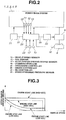
- FIG. 2 is a system configuration view of the hybrid vehicle to which the present invention is applied.
- This hybrid vehicle includes the integrated controller 20 configured to perform an integrated control of the vehicle, an engine controller 21 configured to control the engine 1, and an MG controller 22 configured to control the motor generator 2.
- Integrated controller 20 is connected to the engine controller 21 and the MG controller 22 through communication lines 18 by which information is exchangeable with each other.
- This integrated controller 20 receives the detection signals from the above-described engine speed sensor 10, the MG rotation sensor 11, the AT input rotation sensor 12, and the AT output rotation sensor 13, and also detection signals from various sensors such as a vehicle speed sensor 15 arranged to sense the vehicle speed, an SOC sensor 16 arranged to sense a state of charge (SOC) of a battery 9 arranged to supply the power to the motor generator 2, an accelerator opening degree sensor 17 arranged to sense the accelerator opening degree (APO), and a brake hydraulic pressure sensor 23 arranged to sense a brake hydraulic pressure.
- various sensors such as a vehicle speed sensor 15 arranged to sense the vehicle speed, an SOC sensor 16 arranged to sense a state of charge (SOC) of a battery 9 arranged to supply the power to the motor generator 2, an accelerator opening degree sensor 17 arranged to sense the accelerator opening degree (APO), and a brake hydraulic pressure sensor 23 arranged to sense a brake hydraulic pressure.
- Integrated controller 20 outputs a target MG torque or a target MG rotational speed to the MG controller 22, and outputs a target engine torque to the engine controller 21.
- the first clutch 4 and the second clutch 5 are controlled to be engaged and disengaged based on the command from the integrated controller 20.
- the integrated controller 20 calculates the driving mode of the engine 1 by using the vehicle speed and the accelerator opening degree. That is, it is judged whether it is in a driving state where the engine is to be started, or in a driving state where the engine is to be stopped, by using an engine start stop line map shown in FIG. 3 .
- An engine start line and an engine stop line are varied in a direction (in a downward direction in FIG. 3 ) to decrease the accelerator opening degree as the SOC of the battery 9 is lowered.
- the engine stop line is set in a direction to decrease the accelerator opening degree, relative to the engine start line.
- the accelerator opening degree for stopping the engine 1 (the accelerator opening degree on the engine stop line) is set to be smaller than the accelerator opening degree for starting the engine 1 (the accelerator opening degree on the engine start line).
- the torque capacity of the second clutch 5 is controlled so that the second clutch 5 is slipped to the half clutch state at a timing when the accelerator opening degree exceeds the engine start line shown in FIG. 3 in the EV running state.
- the engagement of the first clutch 4 is started, and the engine speed is increased.
- the engine 1 is actuated.
- the first clutch 4 is fully engaged.
- the second clutch 5 is lockuped so that it is transited to the HEV mode.
- the engine controller 21 controls the engine 1 in accordance with the command from the integrated controller 20.
- the MG controller 22 controls an inverter 8 arranged to drive the motor generator 2, in accordance with the command from the integrated controller 20.
- a power running operation in which the electric power supplied from the battery 9 is applied, a regenerative operation in which the motor generator 9 serves as the generator to charge the battery 9, and the switching between the start and the stop are controlled by the MG controller 22.
- the output (the current value) of the motor generator 2 is monitored by the MG controller 22.
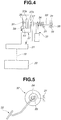
- FIG. 4 the accelerator pedal depression force control apparatus applied to the above-described hybrid vehicle is illustrated by using FIG. 4 and FIG. 5 .
- FIG. 4 is an explanatory view schematically showing a system configuration of an accelerator pedal depression force control apparatus and also a schematic configuration of a depression force varying mechanism.
- FIG. 5 is an explanatory view schematically showing one embodiment of the depression force varying mechanism.
- this accelerator pedal depression force control apparatus is arranged to variably control the depression force (the operation reaction force) of an accelerator pedal 32 provided to a vehicle body 31 of the vehicle (not shown), and to increase the depression force of the accelerator pedal 32 than a base depression force in a region in which the opening degree of the accelerator pedal 32 is greater than a predetermined accelerator opening degree threshold value.
- the accelerator pedal 32 is provided on a rotation shaft 33.
- the accelerator pedal 32 is arranged to be swung about the rotation shaft 33.
- the accelerator pedal 32 receives a reaction force in an accelerator closing direction by a return spring 34 which may have various shapes, and which has one end fixed to the vehicle body 31, and the other end fixed to the rotation shaft 33.
- one end of the rotation shaft 33 is rotatably supported by the vehicle body 31 through a bearing 35.
- the above-described accelerator opening degree sensor 17 serving as an accelerator opening degree sensing section is provided near the other end of the rotation shaft 33.
- a depression amount of the accelerator pedal 32 (the accelerator opening degree) and an opening degree of a throttle valve (not shown) of the engine 1 are coordinated with each other.
- the opening degree of the throttle valve of the engine 1 is increased in accordance with the depression amount of the accelerator pedal 32. That is, a fuel injection amount (and then a fuel consumption amount) is increased in accordance with the accelerator opening degree.
- the depression force varying mechanism is constituted by a variable friction plate 37 including a pair of friction members 37a and 37b which confront each other, and which are arranged to provide the frictional force to the rotation of the rotation shaft 33.
- One friction member 7a is mechanically connected to an end portion of the rotation shaft 3.
- the other friction member 7b is supported through splines and so on to a fix shaft 38 so as to be moved in an axial direction, and so as not to be rotated.
- the fix shaft 38 is fixed to and supported by the vehicle body 31.
- an actuator for example, electromagnetic solenoid
- variable friction plate 37 moves the friction member 37b in the axial direction (in a direction of an arrow A1 in FIG. 4 ) by the actuation of the actuator 39.
- the variable friction plate 37 variably controls the friction force between the friction member 37a and the friction member 37b.
- This actuation of the actuator 39 is controlled by the engine controller 21 based on the command from the integrated controller 20. Accordingly, it is possible to vary the friction force applied to the rotation shaft 33, and then the depression force at the depression of the accelerator pedal 32, by controlling the actuation of the actuator 39 by the engine controller 21.
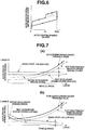
- FIG. 6 schematically shows a characteristic of the accelerator pedal depression force in the above-described embodiment.
- a basic depression force that is, a base depression force has an appropriate hysteresis in the opening degree increasing direction and in the opening degree decreasing direction, and is increased to be substantially proportional to the accelerator opening degree.
- a predetermined accelerator opening degree threshold value (a symbol SL in FIG. 6 ) at the operation in the opening degree increasing direction, that is, at the depression
- the accelerator pedal depression force is increased than the base depression force in a stepped manner. Accordingly, the further depression of the accelerator pedal 32 by the driver is naturally suppressed by increasing the accelerator pedal depression force in the stepped manner.
- the increase of the depression of the accelerator pedal 32 in the above-described accelerator opening degree increasing direction is canceled when the accelerator opening degree becomes equal to or smaller than the above-described predetermined opening degree. However, it may be immediately canceled when the operation direction of the accelerator pedal 32 is turned over (reversed) in the accelerator opening degree decreasing direction.
- the accelerator opening degree threshold value at which the depression force of the accelerator pedal 32 is increased than the base depression force is set by a first accelerator opening degree set based on the accelerator opening degree corresponding to the engine start line shown in FIG. 3 , and a second accelerator opening degree based on the accelerator opening which is a flat road constant speed balancing (equilibrium) opening degree, that is, the second accelerator opening degree set by the accelerator opening degree on an R/L line (road load line) necessary for running the vehicle on the flat road without the acceleration and the deceleration.
- FIGS. 7 are illustrative views showing an example of a characteristic of an accelerator pedal opening degree threshold value.
- FIG. 7(a) shows an example of the characteristic when the SOC of the battery is high.
- FIG. 7(b) shows an example of the characteristic when the SOC of the battery is low.
- the first accelerator opening degree (broken lined in FIG. 7 ) is an accelerator opening degree obtained by subtracting a predetermined accelerator opening degree ⁇ from the accelerator opening on the engine start line (solid lined in FIG. 7 ) which is a threshold value at which the vehicle is switched from the EV running to the HEV running.
- This accelerator opening degree ⁇ is set in consideration of the opening degree that the driver depresses until the depression of the accelerator pedal 32 is stopped by feeling the pedal reaction force.
- the second accelerator opening degree (two-dot chain line in FIG.
- an accelerator opening degree obtained by adding an accelerator opening degree ⁇ which can ensure a driving force by which the vehicle can be accelerated with the constant acceleration, to the accelerator opening degree (which is an accelerator opening degree on the R/L line, and which is chain lines in FIGS. 7 ) by which the vehicle can run at the constant speed on the flat road at each vehicle speed.
- the engine start line is varied in a direction (in the downward direction in FIG. 7 ) in which the accelerator opening degree is decreased when the SOC of the battery 9 is decreased. Accordingly, the first accelerator opening degree is also decreased when the SOC of the battery 9 is decreased.
- the accelerator opening degree threshold value is set only by the first accelerator opening degree, the accelerator opening degree threshold value is relatively decreased as the SOC of the battery 9 is decreased. Accordingly, the driver may be hard to depress the accelerator pedal 32 in a case where the driver wants to depress the accelerator pedal 32.
- the accelerator opening degree threshold value is switched to the second accelerator opening degree.
- the accelerator opening degree threshold value (bold lines in FIG. 7 ) is set as a larger one of the first accelerator opening degree and the second accelerator opening degree at each vehicle speed. That is, the accelerator opening degree threshold value is basically set as the first accelerator opening degree.
- the first accelerator opening degree has a lower limit value defined by the second accelerator opening degree.
- the first accelerator opening degree is set based on the engine start line.
- the lower limit value defined by the second accelerator opening degree is further set with respect to the thus-set first accelerator opening degree.
- the second accelerator opening degree which is the lower limit value of the first accelerator opening degree is the accelerator opening degree that is obtained by adding the accelerator opening amount ⁇ which can ensure the driving force by which the vehicle can be accelerated with the constant acceleration, to the flat road constant speed balancing opening degree by which the vehicle can run at the constant speed at each vehicle speed. Accordingly, it is possible to surely ensure the driving force necessary for the acceleration at each vehicle speed.
- the accelerator opening degree which is the flat road constant speed balancing opening degree is increased as the vehicle speed is increased. Accordingly, the second accelerator opening degree is also increased as the vehicle speed is increased.
- the transmission gear ratio is decreased. Consequently, the vehicle driving force is decreased. Then, the vehicle driving force is decreased, and the acceleration more than necessary is less likely to be generated.
- the second accelerator opening degree which is the lower limit value of the first accelerator opening degree is increased as the vehicle speed is increased. With this, it is possible to ensure the acceleration of the vehicle even at the high vehicle speed.
- the first accelerator opening degree is decreased as the SOC of the battery 9 is decreased since the first accelerator opening degree is set based on the engine start line. That is, the first accelerator opening degree is varied in accordance with the SOC of the battery 9. Accordingly, in a driving state where the first accelerator opening degree is selected as the accelerator opening degree threshold value and the second accelerator opening degree is not selected, the depression force of the accelerator pedal 32 is increased than the base depression force just before the switching from the EV mode to the HEV mode. With this, it is possible to inform the driver of the switching from the EV mode to the HEV mode.
- the first accelerator opening degree is selected as the accelerator opening degree threshold value.
- the depression force of the accelerator pedal 32 is increased than the base depression force just before the switching from the EV mode to the HEV mode. Accordingly, it is possible to inform the driver of the switching from the EV mode to the HEV mode.
- FIG. 8 shows a flowchart showing a flow of the control when the depression force of the accelerator pedal 32 is increased than the base depression force.
- the engine start line is calculated from the SOC of the battery 9 and the vehicle speed, and the first accelerator opening degree is calculated from the engine start line.
- the second accelerator opening degree is calculated from the accelerator opening degree which is previously calculated at each vehicle speed, and by which the vehicle can run at the constant speed on the flat road.
- the larger one of the first accelerator opening degree and the second accelerator opening degree is set to the accelerator opening degree threshold value.
- the process proceeds to S6.
- the accelerator opening degree is not equal to or greater than the accelerator opening degree threshold value, the process proceeds to S7.
- the increase amount of the depression force is decreased since the depression force of the accelerator pedal 32 is increased than the base depression force irrespective of the return state of the accelerator pedal 32.
- the first accelerator opening degree is a value obtained by subtracting the predetermined accelerator opening amount ⁇ from the accelerator opening degree on the engine start line.
- the hybrid vehicle in the above-described embodiment has a structure in which the driving forces of the engine 1 and the motor generator 2 are transmitted to the wheels.
- the present invention is not applied only to the thus-constructed hybrid vehicle.
- the present invention is applicable to various hybrid vehicles such as a hybrid vehicle having a structure in which the engine is used only for the power generation, and a hybrid vehicle having a structure in which the power from the engine is divided into the generator and the motor by a power dividing mechanism.
- the automatic transmission 3 is used as the transmission.
- a continuously variable transmission in which the transmission gear ratio is continuously varied, in place of the automatic transmission 3.
- the continuously variable transmission it is possible to calculate the transmission gear ratio as a ratio between the rotational speeds of the input shaft side and the output shaft side.
- the engine start line and the engine stop line are varied in accordance with the SOC of the battery 9.
- the engine start line and the engine stop line may be varied in accordance with a temperature of the battery 9, a deterioration state of the battery 9, the driving modes such as the sports running mode, and so on.
Landscapes
- Engineering & Computer Science (AREA)
- Chemical & Material Sciences (AREA)
- Combustion & Propulsion (AREA)
- Transportation (AREA)
- Mechanical Engineering (AREA)
- Power Engineering (AREA)
- Automation & Control Theory (AREA)
- Hybrid Electric Vehicles (AREA)
- Electric Propulsion And Braking For Vehicles (AREA)
- Auxiliary Drives, Propulsion Controls, And Safety Devices (AREA)
- Control Of Throttle Valves Provided In The Intake System Or In The Exhaust System (AREA)
Description
- This invention relates to an accelerator pedal depression force control apparatus for a hybrid vehicle.
- The generic patent document
JP 2006 180626 Patent Document 1 discloses an art to vary a depression characteristic of an accelerator pedal at a shift from a first running mode in which the vehicle runs only by the motor to a second running mode in which the vehicle runs by concurrently using the motor and the internal combustion engine, and thereby to increase a resistance force to the depression of the accelerator pedal so as to prevent the deterioration of the fuel economy due to the start of the internal combustion engine by a shift of the running mode against the driver's intension. - In this
Patent Document 1, it is possible to set to vary an accelerator opening degree which increase the resistance force to the depression of the accelerator pedal. However, the accelerator pedal is hard to be depressed when the accelerator opening degree to increase the resistance force to the depression of the accelerator pedal becomes small. Accordingly, there is a problem that the vehicle is hard to be accelerated. - Patent Document 1 : Japanese Patent Application Publication No.
2006-180626 - Therefore, in the present invention, in an accelerator pedal depression force control apparatus for a hybrid vehicle as defined by the features of
claim 1 being configured to increase a depression force of an accelerator pedal than a base depression force when an accelerator opening degree becomes larger than a predetermined accelerator opening degree threshold value, the predetermined accelerator pedal opening degree threshold value is a first accelerator opening degree set based on a mode switching accelerator opening degree which switches from a first running mode in which the vehicle runs by driving only the electric motor to a second running mode in which the internal combustion engine is driven, and a predetermined lower limit value is set to this first accelerator opening degree. - According to the present invention, it is possible to depress the accelerator pedal by the constant amount or more by providing the first accelerator opening degree to the lower limit value. Consequently, it is possible to ensure the acceleration of the vehicle.
-
-
FIG. 1 is an explanatory view schematically showing a schematic configuration of a power train system of a hybrid vehicle to which the present invention is applied. -
FIG. 2 is a system configuration view of the hybrid vehicle to which the present invention is applied. -
FIG. 3 is an explanatory view showing an example of a characteristic of an engine start stop line map. -
FIG. 4 is an explanatory view schematically showing a system configuration of an accelerator pedal depression force control apparatus according to the present invention and also a schematic configuration of a depression force varying mechanism. -
FIG. 5 is an explanatory view schematically showing one embodiment of the depression force varying mechanism in the present invention. -
FIG. 6 is a characteristic view showing a characteristic of the accelerator pedal depression force in the present invention. -
FIGS. 7(a) and (b) show explanatory views showing an example of a characteristic of an accelerator pedal opening degree threshold value.FIG. 7(a) shows an example of the characteristic when the SOC of the battery is high.FIG. 7(b) shows an example of the characteristic when the SOC of the battery is low. -
FIG. 8 is a flowchart showing a flow of a control of the accelerator pedal depression force control apparatus for the hybrid vehicle according to the present invention. - Hereinafter, one embodiment of the present invention will be illustrated in detail with reference to the drawings.
-
FIG. 1 is an explanatory view schematically showing a schematic configuration of a power train of a hybrid vehicle to which the present invention is applied. - An output shaft of an
engine 1 which is an internal combustion engine, and an input shaft of a motor generator 2 (MG) which is an electric motor serving as a generator are connected through a first clutch 4 (CL1) arranged to vary its torque capacity. An output shaft of themotor generator 2 is connected to an input shaft of an automatic transmission 3 (AT). An output shaft of theautomatic transmission 3 is connected through adifferential gear 6 totires 7. - For example, the
automatic transmission 3 is configured to automatically switch stepwise transmission gear ratios such as forward five speeds and one reverse speed, forward six speeds and one reverse speed, and so on (to perform a shift control), in accordance with a vehicle speed, an accelerator opening degree and so on. - One of clutches which can vary the torque capacity, and which serve as different power transmissions within the
automatic transmission 3 in accordance with the shift state is used as a second clutch 5 (CL2). That is, thesecond clutch 5 is one of a plurality of frictional engagement elements provided as shift elements of theautomatic transmission 3. Thesecond clutch 5 uses (diverts) the frictional engagement element existing in a power transmitting path at each gear stage (shift stage), and which is substantially provided within theautomatic transmission 3. - The
automatic transmission 3 combines a power of theengine 1 which is inputted through afirst clutch 4, and a power which is inputted from themotor generator 2, and outputs this combined power to thetires 7. For example, wet-type multiple plate clutches which are capable of continuously controlling flow rate and hydraulic pressure of the hydraulic fluid by proportional solenoids are used in thefirst clutch 4 and thesecond clutch 5. - In this power train system, there are two driving modes according to a connection state of the
first clutch 4. That is, in a disconnection state of thefirst clutch 4, the vehicle becomes an EV mode in which the vehicle runs only by the power of themotor generator 2. In a connection state of thefirst clutch 4, the vehicle becomes an HEV mode in which the vehicle runs by the powers of theengine 1 and themotor generator 2. - In
FIG. 1 , anumeral 10 is an engine speed sensor arranged to sense the engine speed of theengine 1. Anumeral 11 is an MG rotation sensor arranged to sense the rotational speed of themotor generator 2. Anumeral 12 is an AT input rotation sensor arranged to sense a rotational speed of the input shaft of theautomatic transmission 3. Anumeral 13 is an AT output rotation sensor arranged to sense a rotational speed of the output shaft of theautomatic transmission 2. Detection signals of these sensors are inputted to an integratedcontroller 20 described below. -
FIG. 2 is a system configuration view of the hybrid vehicle to which the present invention is applied. This hybrid vehicle includes the integratedcontroller 20 configured to perform an integrated control of the vehicle, anengine controller 21 configured to control theengine 1, and anMG controller 22 configured to control themotor generator 2. -
Integrated controller 20 is connected to theengine controller 21 and the MGcontroller 22 throughcommunication lines 18 by which information is exchangeable with each other. - This integrated
controller 20 receives the detection signals from the above-describedengine speed sensor 10, theMG rotation sensor 11, the ATinput rotation sensor 12, and the AToutput rotation sensor 13, and also detection signals from various sensors such as avehicle speed sensor 15 arranged to sense the vehicle speed, anSOC sensor 16 arranged to sense a state of charge (SOC) of abattery 9 arranged to supply the power to themotor generator 2, an acceleratoropening degree sensor 17 arranged to sense the accelerator opening degree (APO), and a brakehydraulic pressure sensor 23 arranged to sense a brake hydraulic pressure. -
Integrated controller 20 outputs a target MG torque or a target MG rotational speed to the MGcontroller 22, and outputs a target engine torque to theengine controller 21. Thefirst clutch 4 and thesecond clutch 5 are controlled to be engaged and disengaged based on the command from the integratedcontroller 20. - Moreover, the integrated
controller 20 calculates the driving mode of theengine 1 by using the vehicle speed and the accelerator opening degree. That is, it is judged whether it is in a driving state where the engine is to be started, or in a driving state where the engine is to be stopped, by using an engine start stop line map shown inFIG. 3 . An engine start line and an engine stop line are varied in a direction (in a downward direction inFIG. 3 ) to decrease the accelerator opening degree as the SOC of thebattery 9 is lowered. Furthermore, in case of the same state of the SOC of thebattery 9, the engine stop line is set in a direction to decrease the accelerator opening degree, relative to the engine start line. That is, in case of the same state of the SOC of thebattery 9 and the same vehicle speed, the accelerator opening degree for stopping the engine 1 (the accelerator opening degree on the engine stop line) is set to be smaller than the accelerator opening degree for starting the engine 1 (the accelerator opening degree on the engine start line). - In the start operation to start the
engine 1, the torque capacity of thesecond clutch 5 is controlled so that thesecond clutch 5 is slipped to the half clutch state at a timing when the accelerator opening degree exceeds the engine start line shown inFIG. 3 in the EV running state. After it is judged that thesecond clutch 5 is started to be slipped, the engagement of thefirst clutch 4 is started, and the engine speed is increased. Then, when the engine speed reaches the rotational speed by which an initial ignition can be attained, theengine 1 is actuated. When the MG rotational speed and the engine speed are closer to each other, thefirst clutch 4 is fully engaged. Then, thesecond clutch 5 is lockuped so that it is transited to the HEV mode. - The
engine controller 21 controls theengine 1 in accordance with the command from the integratedcontroller 20. - The MG
controller 22 controls aninverter 8 arranged to drive themotor generator 2, in accordance with the command from the integratedcontroller 20. In themotor generator 2, a power running operation in which the electric power supplied from thebattery 9 is applied, a regenerative operation in which themotor generator 9 serves as the generator to charge thebattery 9, and the switching between the start and the stop are controlled by theMG controller 22. The output (the current value) of themotor generator 2 is monitored by theMG controller 22. - Next, the accelerator pedal depression force control apparatus applied to the above-described hybrid vehicle is illustrated by using
FIG. 4 and FIG. 5 . -
FIG. 4 is an explanatory view schematically showing a system configuration of an accelerator pedal depression force control apparatus and also a schematic configuration of a depression force varying mechanism.FIG. 5 is an explanatory view schematically showing one embodiment of the depression force varying mechanism. - Basically, this accelerator pedal depression force control apparatus is arranged to variably control the depression force (the operation reaction force) of an
accelerator pedal 32 provided to avehicle body 31 of the vehicle (not shown), and to increase the depression force of theaccelerator pedal 32 than a base depression force in a region in which the opening degree of theaccelerator pedal 32 is greater than a predetermined accelerator opening degree threshold value. - As shown in
FIGS. 4 and 5 , theaccelerator pedal 32 is provided on arotation shaft 33. Theaccelerator pedal 32 is arranged to be swung about therotation shaft 33. Theaccelerator pedal 32 receives a reaction force in an accelerator closing direction by areturn spring 34 which may have various shapes, and which has one end fixed to thevehicle body 31, and the other end fixed to therotation shaft 33. Moreover, one end of therotation shaft 33 is rotatably supported by thevehicle body 31 through abearing 35. On the other hand, the above-described acceleratoropening degree sensor 17 serving as an accelerator opening degree sensing section is provided near the other end of therotation shaft 33. - In this embodiment, a depression amount of the accelerator pedal 32 (the accelerator opening degree) and an opening degree of a throttle valve (not shown) of the
engine 1 are coordinated with each other. The opening degree of the throttle valve of theengine 1 is increased in accordance with the depression amount of theaccelerator pedal 32. That is, a fuel injection amount (and then a fuel consumption amount) is increased in accordance with the accelerator opening degree. - The depression force varying mechanism is constituted by a
variable friction plate 37 including a pair offriction members rotation shaft 33. One friction member 7a is mechanically connected to an end portion of therotation shaft 3. The other friction member 7b is supported through splines and so on to afix shaft 38 so as to be moved in an axial direction, and so as not to be rotated. Thefix shaft 38 is fixed to and supported by thevehicle body 31. Moreover, an actuator (for example, electromagnetic solenoid) 39 arranged to urge thefriction member 37b toward thefriction member 37a is fixed to thevehicle body 31. - The
variable friction plate 37 moves thefriction member 37b in the axial direction (in a direction of an arrow A1 inFIG. 4 ) by the actuation of theactuator 39. With this, thevariable friction plate 37 variably controls the friction force between thefriction member 37a and thefriction member 37b. This actuation of theactuator 39 is controlled by theengine controller 21 based on the command from the integratedcontroller 20. Accordingly, it is possible to vary the friction force applied to therotation shaft 33, and then the depression force at the depression of theaccelerator pedal 32, by controlling the actuation of theactuator 39 by theengine controller 21. -
FIG. 6 schematically shows a characteristic of the accelerator pedal depression force in the above-described embodiment. A basic depression force, that is, a base depression force has an appropriate hysteresis in the opening degree increasing direction and in the opening degree decreasing direction, and is increased to be substantially proportional to the accelerator opening degree. When the accelerator opening degree becomes greater than a predetermined accelerator opening degree threshold value (a symbol SL inFIG. 6 ) at the operation in the opening degree increasing direction, that is, at the depression, the accelerator pedal depression force is increased than the base depression force in a stepped manner. Accordingly, the further depression of theaccelerator pedal 32 by the driver is naturally suppressed by increasing the accelerator pedal depression force in the stepped manner. - In this embodiment, the increase of the depression of the
accelerator pedal 32 in the above-described accelerator opening degree increasing direction is canceled when the accelerator opening degree becomes equal to or smaller than the above-described predetermined opening degree. However, it may be immediately canceled when the operation direction of theaccelerator pedal 32 is turned over (reversed) in the accelerator opening degree decreasing direction. - In this embodiment, the accelerator opening degree threshold value at which the depression force of the
accelerator pedal 32 is increased than the base depression force is set by a first accelerator opening degree set based on the accelerator opening degree corresponding to the engine start line shown inFIG. 3 , and a second accelerator opening degree based on the accelerator opening which is a flat road constant speed balancing (equilibrium) opening degree, that is, the second accelerator opening degree set by the accelerator opening degree on an R/L line (road load line) necessary for running the vehicle on the flat road without the acceleration and the deceleration. -
FIGS. 7 are illustrative views showing an example of a characteristic of an accelerator pedal opening degree threshold value.FIG. 7(a) shows an example of the characteristic when the SOC of the battery is high.FIG. 7(b) shows an example of the characteristic when the SOC of the battery is low. - The first accelerator opening degree (broken lined in
FIG. 7 ) is an accelerator opening degree obtained by subtracting a predetermined accelerator opening degree α from the accelerator opening on the engine start line (solid lined inFIG. 7 ) which is a threshold value at which the vehicle is switched from the EV running to the HEV running. This accelerator opening degree α is set in consideration of the opening degree that the driver depresses until the depression of theaccelerator pedal 32 is stopped by feeling the pedal reaction force. The second accelerator opening degree (two-dot chain line inFIG. 7 ) is an accelerator opening degree obtained by adding an accelerator opening degree β which can ensure a driving force by which the vehicle can be accelerated with the constant acceleration, to the accelerator opening degree (which is an accelerator opening degree on the R/L line, and which is chain lines inFIGS. 7 ) by which the vehicle can run at the constant speed on the flat road at each vehicle speed. - As illustrated in detail by using
FIGS. 7 , the engine start line is varied in a direction (in the downward direction inFIG. 7 ) in which the accelerator opening degree is decreased when the SOC of thebattery 9 is decreased. Accordingly, the first accelerator opening degree is also decreased when the SOC of thebattery 9 is decreased. In a case where the accelerator opening degree threshold value is set only by the first accelerator opening degree, the accelerator opening degree threshold value is relatively decreased as the SOC of thebattery 9 is decreased. Accordingly, the driver may be hard to depress theaccelerator pedal 32 in a case where the driver wants to depress theaccelerator pedal 32. However, in this embodiment, when the first accelerator opening degree becomes smaller than the second accelerator opening degree, the accelerator opening degree threshold value is switched to the second accelerator opening degree. That is, in this embodiment, the accelerator opening degree threshold value (bold lines inFIG. 7 ) is set as a larger one of the first accelerator opening degree and the second accelerator opening degree at each vehicle speed. That is, the accelerator opening degree threshold value is basically set as the first accelerator opening degree. The first accelerator opening degree has a lower limit value defined by the second accelerator opening degree. - In this way, the first accelerator opening degree is set based on the engine start line. The lower limit value defined by the second accelerator opening degree is further set with respect to the thus-set first accelerator opening degree. With this, it is possible to prevent that the driver is hard to depress the
accelerator pedal 32 when the driver want to depress theaccelerator pedal 32. Moreover, it is possible to depress theaccelerator pedal 32 by the constant amount or more, and thereby to ensure the good acceleration of the vehicle. - In particular, the second accelerator opening degree which is the lower limit value of the first accelerator opening degree is the accelerator opening degree that is obtained by adding the accelerator opening amount β which can ensure the driving force by which the vehicle can be accelerated with the constant acceleration, to the flat road constant speed balancing opening degree by which the vehicle can run at the constant speed at each vehicle speed. Accordingly, it is possible to surely ensure the driving force necessary for the acceleration at each vehicle speed.
- Furthermore, the accelerator opening degree which is the flat road constant speed balancing opening degree is increased as the vehicle speed is increased. Accordingly, the second accelerator opening degree is also increased as the vehicle speed is increased. When the vehicle speed is increased, the transmission gear ratio is decreased. Consequently, the vehicle driving force is decreased. Then, the vehicle driving force is decreased, and the acceleration more than necessary is less likely to be generated. In this way, the second accelerator opening degree which is the lower limit value of the first accelerator opening degree is increased as the vehicle speed is increased. With this, it is possible to ensure the acceleration of the vehicle even at the high vehicle speed.
- Moreover, when the SOC of the
battery 9 is decreased, the maximum torque which can be generated by themotor generator 2 is decreased. Accordingly, it is necessary to decrease the driving region of the EV mode. However, the first accelerator opening degree is decreased as the SOC of thebattery 9 is decreased since the first accelerator opening degree is set based on the engine start line. That is, the first accelerator opening degree is varied in accordance with the SOC of thebattery 9. Accordingly, in a driving state where the first accelerator opening degree is selected as the accelerator opening degree threshold value and the second accelerator opening degree is not selected, the depression force of theaccelerator pedal 32 is increased than the base depression force just before the switching from the EV mode to the HEV mode. With this, it is possible to inform the driver of the switching from the EV mode to the HEV mode. - That is, as shown in
FIGS. 7 , in a state where the first accelerator opening degree is larger than the second accelerator opening degree and the vehicle speed is low, the first accelerator opening degree is selected as the accelerator opening degree threshold value. With this, the depression force of theaccelerator pedal 32 is increased than the base depression force just before the switching from the EV mode to the HEV mode. Accordingly, it is possible to inform the driver of the switching from the EV mode to the HEV mode. -
FIG. 8 shows a flowchart showing a flow of the control when the depression force of theaccelerator pedal 32 is increased than the base depression force. - At S1, the vehicle speed, the accelerator opening degree, and the SOC of the
battery 9 are calculated. - At S2, the engine start line is calculated from the SOC of the
battery 9 and the vehicle speed, and the first accelerator opening degree is calculated from the engine start line. - At S3, the second accelerator opening degree is calculated from the accelerator opening degree which is previously calculated at each vehicle speed, and by which the vehicle can run at the constant speed on the flat road.
- At S4, the larger one of the first accelerator opening degree and the second accelerator opening degree is set to the accelerator opening degree threshold value. At S5, it is judged whether or not the accelerator opening degree is equal to or greater than the accelerator opening degree threshold value. When the accelerator opening degree is equal to or greater than the accelerator opening degree threshold value, the process proceeds to S6. When the accelerator opening degree is not equal to or greater than the accelerator opening degree threshold value, the process proceeds to S7.
- At S6, the depression force of the
accelerator pedal 32 is increased than the base depression force. - At S7, it is judged whether or not the depression force is increased than the base depression force. When the depression force is increased than the base depression force, the process proceeds to S8. When the depression force is increased, this routine is finished.
- At S8, it is judged whether or not the accelerator opening degree is equal to or smaller than a predetermined cancel threshold value smaller than the accelerator opening degree threshold value. When the accelerator opening degree is equal to or smaller than the cancel threshold value, the process proceeds to S9. When the accelerator opening degree is not equal to or smaller than the cancel threshold value, this routine is finished.
- At S9, the increase amount of the depression force is decreased since the depression force of the
accelerator pedal 32 is increased than the base depression force irrespective of the return state of theaccelerator pedal 32. - Besides, in the above-described embodiment, the first accelerator opening degree is a value obtained by subtracting the predetermined accelerator opening amount α from the accelerator opening degree on the engine start line. However, it is possible to set the accelerator opening degree on the engine start line, directly to the first accelerator opening degree. That is, it is possible to set the engine start line to the first accelerator opening degree.
- The hybrid vehicle in the above-described embodiment has a structure in which the driving forces of the
engine 1 and themotor generator 2 are transmitted to the wheels. However, the present invention is not applied only to the thus-constructed hybrid vehicle. For example, the present invention is applicable to various hybrid vehicles such as a hybrid vehicle having a structure in which the engine is used only for the power generation, and a hybrid vehicle having a structure in which the power from the engine is divided into the generator and the motor by a power dividing mechanism. - Moreover, in the above-described embodiment, the
automatic transmission 3 is used as the transmission. However, it is possible to use a continuously variable transmission in which the transmission gear ratio is continuously varied, in place of theautomatic transmission 3. In case of the continuously variable transmission, it is possible to calculate the transmission gear ratio as a ratio between the rotational speeds of the input shaft side and the output shaft side. - Moreover, in the above-described embodiment, the engine start line and the engine stop line are varied in accordance with the SOC of the
battery 9. However, the engine start line and the engine stop line may be varied in accordance with a temperature of thebattery 9, a deterioration state of thebattery 9, the driving modes such as the sports running mode, and so on.
Claims (6)
- An accelerator pedal depression force control apparatus for a hybrid vehicle including an internal combustion engine, an electric motor which is used as a driving source when the vehicle runs, said apparatus comprising:a depression force varying means configured to vary a depression force of an accelerator pedal (32)characterised in that said accelerator pedal depression force control apparatus is arranged to increase the depression force of the accelerator pedal (32) than a base depression force when the accelerator opening degree becomes larger than an accelerator opening degree threshold value,to set a first accelerator opening degree based on an accelerator opening degree which switches from a first running mode in which the vehicle runs by driving only the electric motor, to a second running mode in which the internal combustion engine is driven,to set a second accelerator opening degree based on the accelerator opening degree by which the vehicle can run at a constant speed at each vehicle speed, andto set the accelerator opening degree threshold value as a larger one of the first accelerator opening degree and the second accelerator opening degree.
- The accelerator pedal depression force control apparatus for the hybrid vehicle as claimed in Claim 1, wherein the second accelerator opening degree is set to be increased as the vehicle speed is increased.
- The accelerator pedal depression force control apparatus for the hybrid vehicle as claimed in Claims 1 or 2, wherein the first accelerator opening degree is set to be varied in accordance with a state (SOC) of a battery which is a driving source of the electric motor.
- The accelerator pedal depression force control apparatus for the hybrid vehicle as claimed in one of Claims 1 to 3, wherein the first accelerator opening degree is set to be decreased as the SOC of the battery is decreased.
- The accelerator pedal depression force control apparatus for the hybrid vehicle as claimed in one of Claims 1 to 4, wherein the first accelerator opening degree is set by subtracting a predetermined accelerator opening amount from the accelerator opening degree on an engine start line at which the hybrid vehicle is switched from the first running mode to the second running mode.
- The accelerator pedal depression force control apparatus for the hybrid vehicle as claimed in one of Claims 1 to 5, wherein the second accelerator opening degree is set by an accelerator opening degree obtained bv adding an accelerator opening amount which can ensure a driving force by which the vehicle can be accelerated with a constant acceleration, to the accelerator opening degree bv which the vehicle can run at the constant speed on a flat road at each vehicle speed.
Applications Claiming Priority (2)
| Application Number | Priority Date | Filing Date | Title |
|---|---|---|---|
| JP2010118920A JP5471829B2 (en) | 2010-05-25 | 2010-05-25 | Accelerator pedal force control device for hybrid vehicle |
| PCT/JP2011/060305 WO2011148753A1 (en) | 2010-05-25 | 2011-04-27 | Hybrid vehicle accelerator pedal depressing force control device |
Publications (3)
| Publication Number | Publication Date |
|---|---|
| EP2578432A1 EP2578432A1 (en) | 2013-04-10 |
| EP2578432A4 EP2578432A4 (en) | 2018-03-21 |
| EP2578432B1 true EP2578432B1 (en) | 2019-06-12 |
Family
ID=45003745
Family Applications (1)
| Application Number | Title | Priority Date | Filing Date |
|---|---|---|---|
| EP11786453.8A Active EP2578432B1 (en) | 2010-05-25 | 2011-04-27 | Hybrid vehicle accelerator pedal depressing force control device |
Country Status (9)
| Country | Link |
|---|---|
| US (1) | US8620566B2 (en) |
| EP (1) | EP2578432B1 (en) |
| JP (1) | JP5471829B2 (en) |
| KR (1) | KR101420959B1 (en) |
| CN (1) | CN102905927B (en) |
| BR (1) | BR112012030026A2 (en) |
| MX (1) | MX2012013367A (en) |
| RU (1) | RU2527652C2 (en) |
| WO (1) | WO2011148753A1 (en) |
Families Citing this family (15)
| Publication number | Priority date | Publication date | Assignee | Title |
|---|---|---|---|---|
| JP5381321B2 (en) * | 2008-07-31 | 2014-01-08 | 日産自動車株式会社 | Accelerator pedal force control device |
| US20120047087A1 (en) * | 2009-03-25 | 2012-02-23 | Waldeck Technology Llc | Smart encounters |
| CN104755305B (en) * | 2012-11-21 | 2017-06-13 | 本田技研工业株式会社 | Accelerator pedal reaction force control device and vehicle |
| KR101406533B1 (en) * | 2013-04-16 | 2014-06-12 | 기아자동차주식회사 | Active control method of accelerator pedal effort |
| KR101406654B1 (en) * | 2013-04-23 | 2014-06-11 | 기아자동차주식회사 | Active control method of accelerator pedal effort |
| JP2015048052A (en) * | 2013-09-04 | 2015-03-16 | トヨタ自動車株式会社 | Attachment structure of pedal device |
| US9162674B2 (en) | 2013-10-24 | 2015-10-20 | Ford Global Technologies, Llc | Dynamic mapping of pedal position to wheel output demand in a hybrid vehicle |
| CN105555578B (en) * | 2013-10-30 | 2018-01-16 | 本田技研工业株式会社 | Pedal Reaction Force Controller |
| GB2523589B (en) * | 2014-02-28 | 2020-04-22 | Bentley Motors Ltd | Hybrid drive system |
| US9290094B2 (en) | 2014-04-01 | 2016-03-22 | Atieva, Inc. | Dual stage accelerator assembly with pedal feedback system |
| WO2016031202A1 (en) * | 2014-08-29 | 2016-03-03 | マツダ株式会社 | Vehicular accelerator pedal reaction force control device |
| FR3070945B1 (en) * | 2017-09-08 | 2019-09-13 | Psa Automobiles Sa | SUPPLY CONTROL OF A COMPLEMENTARY TORQUE BY A NON-THERMAL MOTOR MACHINE OF A HYBRID VEHICLE BASED ON ACCELERATION POTENTIAL |
| JP6521491B1 (en) * | 2017-12-01 | 2019-05-29 | マツダ株式会社 | Vehicle control device |
| RU2681805C1 (en) * | 2018-04-10 | 2019-03-12 | Сергей Николаевич Низов | Accelerator assembly of internal combustion engine with turbo-supercharge |
| JP7447720B2 (en) | 2020-07-20 | 2024-03-12 | 日産自動車株式会社 | Engine control method and engine control device |
Family Cites Families (12)
| Publication number | Priority date | Publication date | Assignee | Title |
|---|---|---|---|---|
| SU142540A1 (en) * | 1958-08-12 | 1960-11-30 | В.К. Зорин | A device that facilitates driving |
| SU1244653A1 (en) * | 1983-06-06 | 1986-07-15 | Опытно-Механический Завод Главленстройматериалов | Device for controlling working member |
| AU2003248064A1 (en) * | 2002-09-13 | 2004-04-30 | Honda Giken Kogyo Kabushiki Kaisha | Hybrid vehicle |
| EP1524145A3 (en) * | 2003-10-15 | 2006-01-04 | Nissan Motor Company, Limited | Drive train for hybrid vehicle |
| JP4367089B2 (en) * | 2003-10-30 | 2009-11-18 | 日産自動車株式会社 | Accelerator pedal force control device |
| JP4135107B2 (en) * | 2004-11-04 | 2008-08-20 | アイシン・エィ・ダブリュ株式会社 | Hybrid vehicle drive device and control method thereof |
| JP2006180626A (en) * | 2004-12-22 | 2006-07-06 | Toyota Motor Corp | Control device of hybrid vehicle |
| JP5082243B2 (en) * | 2006-01-10 | 2012-11-28 | トヨタ自動車株式会社 | Vehicle driving assistance device |
| JP4462219B2 (en) * | 2006-03-28 | 2010-05-12 | トヨタ自動車株式会社 | Hybrid vehicle and control method thereof |
| DE102008000577A1 (en) * | 2008-03-10 | 2009-09-17 | Robert Bosch Gmbh | Method and device for operating a vehicle with hybrid drive |
| JP4553057B2 (en) * | 2008-07-31 | 2010-09-29 | 日産自動車株式会社 | Accelerator pedal depression force control device and method |
| JP5381321B2 (en) * | 2008-07-31 | 2014-01-08 | 日産自動車株式会社 | Accelerator pedal force control device |
-
2010
- 2010-05-25 JP JP2010118920A patent/JP5471829B2/en active Active
-
2011
- 2011-04-27 BR BR112012030026A patent/BR112012030026A2/en not_active IP Right Cessation
- 2011-04-27 EP EP11786453.8A patent/EP2578432B1/en active Active
- 2011-04-27 KR KR1020127030745A patent/KR101420959B1/en not_active IP Right Cessation
- 2011-04-27 MX MX2012013367A patent/MX2012013367A/en active IP Right Grant
- 2011-04-27 RU RU2012156160/11A patent/RU2527652C2/en not_active IP Right Cessation
- 2011-04-27 US US13/699,174 patent/US8620566B2/en active Active
- 2011-04-27 WO PCT/JP2011/060305 patent/WO2011148753A1/en active Application Filing
- 2011-04-27 CN CN201180025688.3A patent/CN102905927B/en active Active
Non-Patent Citations (1)
| Title |
|---|
| None * |
Also Published As
| Publication number | Publication date |
|---|---|
| KR101420959B1 (en) | 2014-07-17 |
| RU2012156160A (en) | 2014-06-27 |
| CN102905927B (en) | 2015-09-30 |
| EP2578432A4 (en) | 2018-03-21 |
| US20130066508A1 (en) | 2013-03-14 |
| RU2527652C2 (en) | 2014-09-10 |
| MX2012013367A (en) | 2013-01-24 |
| EP2578432A1 (en) | 2013-04-10 |
| JP2011245919A (en) | 2011-12-08 |
| JP5471829B2 (en) | 2014-04-16 |
| US8620566B2 (en) | 2013-12-31 |
| WO2011148753A1 (en) | 2011-12-01 |
| KR20130004521A (en) | 2013-01-10 |
| BR112012030026A2 (en) | 2016-08-02 |
| CN102905927A (en) | 2013-01-30 |
Similar Documents
| Publication | Publication Date | Title |
|---|---|---|
| EP2578432B1 (en) | Hybrid vehicle accelerator pedal depressing force control device | |
| US9694821B2 (en) | Drive control device for vehicle | |
| US9440653B2 (en) | Drive control device for vehicle | |
| EP2574515B1 (en) | Control device for hybrid vehicle | |
| US9573584B2 (en) | Hybrid vehicle control device | |
| US9604628B2 (en) | Powertrain control of a hybrid vehicle in park or neutral | |
| US20140129067A1 (en) | Control device of vehicle | |
| CN103010205B (en) | The power transmission controller of vehicle | |
| EP2653363B1 (en) | Power transmission control device for vehicle | |
| JP7298179B2 (en) | Electric vehicle control method and electric vehicle drive system | |
| JP5322751B2 (en) | Vehicle power transmission control device | |
| CN109072998B (en) | Vehicle control device | |
| US10279795B2 (en) | Control device | |
| JP5374914B2 (en) | Control device for hybrid vehicle | |
| JP2006347408A (en) | System and method for controlling automobile, and automobile | |
| JP5803626B2 (en) | Vehicle control device | |
| WO2014068399A1 (en) | Drive control device and method for vehicle | |
| JP2012091620A (en) | Engine start control device of hybrid vehicle | |
| JP2011194940A (en) | Controller for hybrid vehicle | |
| WO2012077382A1 (en) | Vehicle power transmission control device | |
| JP2007261494A (en) | Control device for vehicle |
Legal Events
| Date | Code | Title | Description |
|---|---|---|---|
| PUAI | Public reference made under article 153(3) epc to a published international application that has entered the european phase |
Free format text: ORIGINAL CODE: 0009012 |
|
| 17P | Request for examination filed |
Effective date: 20121227 |
|
| AK | Designated contracting states |
Kind code of ref document: A1 Designated state(s): AL AT BE BG CH CY CZ DE DK EE ES FI FR GB GR HR HU IE IS IT LI LT LU LV MC MK MT NL NO PL PT RO RS SE SI SK SM TR |
|
| DAX | Request for extension of the european patent (deleted) | ||
| RA4 | Supplementary search report drawn up and despatched (corrected) |
Effective date: 20180219 |
|
| RIC1 | Information provided on ipc code assigned before grant |
Ipc: B60L 11/14 20060101ALI20180213BHEP Ipc: B60K 6/48 20071001ALI20180213BHEP Ipc: B60W 20/00 20160101ALI20180213BHEP Ipc: B60K 26/02 20060101AFI20180213BHEP Ipc: B60W 10/00 20060101ALI20180213BHEP |
|
| REG | Reference to a national code |
Ref country code: DE Ref legal event code: R079 Ref document number: 602011059685 Country of ref document: DE Free format text: PREVIOUS MAIN CLASS: B60K0026040000 Ipc: B60K0026020000 |
|
| RIC1 | Information provided on ipc code assigned before grant |
Ipc: B60K 6/48 20071001ALI20181213BHEP Ipc: B60K 26/02 20060101AFI20181213BHEP Ipc: B60W 10/00 20060101ALI20181213BHEP Ipc: B60W 20/00 20160101ALI20181213BHEP Ipc: B60L 11/14 20060101ALI20181213BHEP |
|
| RIC1 | Information provided on ipc code assigned before grant |
Ipc: B60W 10/00 20060101ALI20181213BHEP Ipc: B60K 26/02 20060101AFI20181213BHEP Ipc: B60W 20/00 20160101ALI20181213BHEP Ipc: B60K 6/48 20071001ALI20181213BHEP Ipc: B60L 11/14 20060101ALI20181213BHEP |
|
| GRAP | Despatch of communication of intention to grant a patent |
Free format text: ORIGINAL CODE: EPIDOSNIGR1 |
|
| STAA | Information on the status of an ep patent application or granted ep patent |
Free format text: STATUS: GRANT OF PATENT IS INTENDED |
|
| RIC1 | Information provided on ipc code assigned before grant |
Ipc: B60K 26/02 20060101AFI20190114BHEP Ipc: B60K 6/48 20071001ALI20190114BHEP Ipc: B60W 10/00 20060101ALI20190114BHEP Ipc: B60W 20/00 20160101ALI20190114BHEP |
|
| INTG | Intention to grant announced |
Effective date: 20190215 |
|
| GRAS | Grant fee paid |
Free format text: ORIGINAL CODE: EPIDOSNIGR3 |
|
| GRAA | (expected) grant |
Free format text: ORIGINAL CODE: 0009210 |
|
| STAA | Information on the status of an ep patent application or granted ep patent |
Free format text: STATUS: THE PATENT HAS BEEN GRANTED |
|
| AK | Designated contracting states |
Kind code of ref document: B1 Designated state(s): AL AT BE BG CH CY CZ DE DK EE ES FI FR GB GR HR HU IE IS IT LI LT LU LV MC MK MT NL NO PL PT RO RS SE SI SK SM TR |
|
| REG | Reference to a national code |
Ref country code: GB Ref legal event code: FG4D |
|
| REG | Reference to a national code |
Ref country code: CH Ref legal event code: EP |
|
| REG | Reference to a national code |
Ref country code: AT Ref legal event code: REF Ref document number: 1142111 Country of ref document: AT Kind code of ref document: T Effective date: 20190615 |
|
| REG | Reference to a national code |
Ref country code: DE Ref legal event code: R096 Ref document number: 602011059685 Country of ref document: DE |
|
| REG | Reference to a national code |
Ref country code: IE Ref legal event code: FG4D |
|
| REG | Reference to a national code |
Ref country code: NL Ref legal event code: MP Effective date: 20190612 |
|
| REG | Reference to a national code |
Ref country code: LT Ref legal event code: MG4D |
|
| PG25 | Lapsed in a contracting state [announced via postgrant information from national office to epo] |
Ref country code: AL Free format text: LAPSE BECAUSE OF FAILURE TO SUBMIT A TRANSLATION OF THE DESCRIPTION OR TO PAY THE FEE WITHIN THE PRESCRIBED TIME-LIMIT Effective date: 20190612 Ref country code: SE Free format text: LAPSE BECAUSE OF FAILURE TO SUBMIT A TRANSLATION OF THE DESCRIPTION OR TO PAY THE FEE WITHIN THE PRESCRIBED TIME-LIMIT Effective date: 20190612 Ref country code: LT Free format text: LAPSE BECAUSE OF FAILURE TO SUBMIT A TRANSLATION OF THE DESCRIPTION OR TO PAY THE FEE WITHIN THE PRESCRIBED TIME-LIMIT Effective date: 20190612 Ref country code: HR Free format text: LAPSE BECAUSE OF FAILURE TO SUBMIT A TRANSLATION OF THE DESCRIPTION OR TO PAY THE FEE WITHIN THE PRESCRIBED TIME-LIMIT Effective date: 20190612 Ref country code: ES Free format text: LAPSE BECAUSE OF FAILURE TO SUBMIT A TRANSLATION OF THE DESCRIPTION OR TO PAY THE FEE WITHIN THE PRESCRIBED TIME-LIMIT Effective date: 20190612 Ref country code: FI Free format text: LAPSE BECAUSE OF FAILURE TO SUBMIT A TRANSLATION OF THE DESCRIPTION OR TO PAY THE FEE WITHIN THE PRESCRIBED TIME-LIMIT Effective date: 20190612 Ref country code: NO Free format text: LAPSE BECAUSE OF FAILURE TO SUBMIT A TRANSLATION OF THE DESCRIPTION OR TO PAY THE FEE WITHIN THE PRESCRIBED TIME-LIMIT Effective date: 20190912 |
|
| PG25 | Lapsed in a contracting state [announced via postgrant information from national office to epo] |
Ref country code: RS Free format text: LAPSE BECAUSE OF FAILURE TO SUBMIT A TRANSLATION OF THE DESCRIPTION OR TO PAY THE FEE WITHIN THE PRESCRIBED TIME-LIMIT Effective date: 20190612 Ref country code: BG Free format text: LAPSE BECAUSE OF FAILURE TO SUBMIT A TRANSLATION OF THE DESCRIPTION OR TO PAY THE FEE WITHIN THE PRESCRIBED TIME-LIMIT Effective date: 20190912 Ref country code: GR Free format text: LAPSE BECAUSE OF FAILURE TO SUBMIT A TRANSLATION OF THE DESCRIPTION OR TO PAY THE FEE WITHIN THE PRESCRIBED TIME-LIMIT Effective date: 20190913 Ref country code: LV Free format text: LAPSE BECAUSE OF FAILURE TO SUBMIT A TRANSLATION OF THE DESCRIPTION OR TO PAY THE FEE WITHIN THE PRESCRIBED TIME-LIMIT Effective date: 20190612 |
|
| REG | Reference to a national code |
Ref country code: AT Ref legal event code: MK05 Ref document number: 1142111 Country of ref document: AT Kind code of ref document: T Effective date: 20190612 |
|
| PG25 | Lapsed in a contracting state [announced via postgrant information from national office to epo] |
Ref country code: NL Free format text: LAPSE BECAUSE OF FAILURE TO SUBMIT A TRANSLATION OF THE DESCRIPTION OR TO PAY THE FEE WITHIN THE PRESCRIBED TIME-LIMIT Effective date: 20190612 Ref country code: PT Free format text: LAPSE BECAUSE OF FAILURE TO SUBMIT A TRANSLATION OF THE DESCRIPTION OR TO PAY THE FEE WITHIN THE PRESCRIBED TIME-LIMIT Effective date: 20191014 Ref country code: RO Free format text: LAPSE BECAUSE OF FAILURE TO SUBMIT A TRANSLATION OF THE DESCRIPTION OR TO PAY THE FEE WITHIN THE PRESCRIBED TIME-LIMIT Effective date: 20190612 Ref country code: SK Free format text: LAPSE BECAUSE OF FAILURE TO SUBMIT A TRANSLATION OF THE DESCRIPTION OR TO PAY THE FEE WITHIN THE PRESCRIBED TIME-LIMIT Effective date: 20190612 Ref country code: CZ Free format text: LAPSE BECAUSE OF FAILURE TO SUBMIT A TRANSLATION OF THE DESCRIPTION OR TO PAY THE FEE WITHIN THE PRESCRIBED TIME-LIMIT Effective date: 20190612 Ref country code: AT Free format text: LAPSE BECAUSE OF FAILURE TO SUBMIT A TRANSLATION OF THE DESCRIPTION OR TO PAY THE FEE WITHIN THE PRESCRIBED TIME-LIMIT Effective date: 20190612 Ref country code: EE Free format text: LAPSE BECAUSE OF FAILURE TO SUBMIT A TRANSLATION OF THE DESCRIPTION OR TO PAY THE FEE WITHIN THE PRESCRIBED TIME-LIMIT Effective date: 20190612 |
|
| PG25 | Lapsed in a contracting state [announced via postgrant information from national office to epo] |
Ref country code: IT Free format text: LAPSE BECAUSE OF FAILURE TO SUBMIT A TRANSLATION OF THE DESCRIPTION OR TO PAY THE FEE WITHIN THE PRESCRIBED TIME-LIMIT Effective date: 20190612 Ref country code: IS Free format text: LAPSE BECAUSE OF FAILURE TO SUBMIT A TRANSLATION OF THE DESCRIPTION OR TO PAY THE FEE WITHIN THE PRESCRIBED TIME-LIMIT Effective date: 20191012 Ref country code: SM Free format text: LAPSE BECAUSE OF FAILURE TO SUBMIT A TRANSLATION OF THE DESCRIPTION OR TO PAY THE FEE WITHIN THE PRESCRIBED TIME-LIMIT Effective date: 20190612 |
|
| REG | Reference to a national code |
Ref country code: DE Ref legal event code: R097 Ref document number: 602011059685 Country of ref document: DE |
|
| PG25 | Lapsed in a contracting state [announced via postgrant information from national office to epo] |
Ref country code: TR Free format text: LAPSE BECAUSE OF FAILURE TO SUBMIT A TRANSLATION OF THE DESCRIPTION OR TO PAY THE FEE WITHIN THE PRESCRIBED TIME-LIMIT Effective date: 20190612 |
|
| PLBE | No opposition filed within time limit |
Free format text: ORIGINAL CODE: 0009261 |
|
| STAA | Information on the status of an ep patent application or granted ep patent |
Free format text: STATUS: NO OPPOSITION FILED WITHIN TIME LIMIT |
|
| PG25 | Lapsed in a contracting state [announced via postgrant information from national office to epo] |
Ref country code: PL Free format text: LAPSE BECAUSE OF FAILURE TO SUBMIT A TRANSLATION OF THE DESCRIPTION OR TO PAY THE FEE WITHIN THE PRESCRIBED TIME-LIMIT Effective date: 20190612 Ref country code: DK Free format text: LAPSE BECAUSE OF FAILURE TO SUBMIT A TRANSLATION OF THE DESCRIPTION OR TO PAY THE FEE WITHIN THE PRESCRIBED TIME-LIMIT Effective date: 20190612 |
|
| 26N | No opposition filed |
Effective date: 20200313 |
|
| PG25 | Lapsed in a contracting state [announced via postgrant information from national office to epo] |
Ref country code: IS Free format text: LAPSE BECAUSE OF FAILURE TO SUBMIT A TRANSLATION OF THE DESCRIPTION OR TO PAY THE FEE WITHIN THE PRESCRIBED TIME-LIMIT Effective date: 20200224 Ref country code: SI Free format text: LAPSE BECAUSE OF FAILURE TO SUBMIT A TRANSLATION OF THE DESCRIPTION OR TO PAY THE FEE WITHIN THE PRESCRIBED TIME-LIMIT Effective date: 20190612 |
|
| PG2D | Information on lapse in contracting state deleted |
Ref country code: IS |
|
| PG25 | Lapsed in a contracting state [announced via postgrant information from national office to epo] |
Ref country code: MC Free format text: LAPSE BECAUSE OF FAILURE TO SUBMIT A TRANSLATION OF THE DESCRIPTION OR TO PAY THE FEE WITHIN THE PRESCRIBED TIME-LIMIT Effective date: 20190612 |
|
| REG | Reference to a national code |
Ref country code: CH Ref legal event code: PL |
|
| PG25 | Lapsed in a contracting state [announced via postgrant information from national office to epo] |
Ref country code: LU Free format text: LAPSE BECAUSE OF NON-PAYMENT OF DUE FEES Effective date: 20200427 Ref country code: LI Free format text: LAPSE BECAUSE OF NON-PAYMENT OF DUE FEES Effective date: 20200430 Ref country code: CH Free format text: LAPSE BECAUSE OF NON-PAYMENT OF DUE FEES Effective date: 20200430 |
|
| REG | Reference to a national code |
Ref country code: BE Ref legal event code: MM Effective date: 20200430 |
|
| PG25 | Lapsed in a contracting state [announced via postgrant information from national office to epo] |
Ref country code: BE Free format text: LAPSE BECAUSE OF NON-PAYMENT OF DUE FEES Effective date: 20200430 |
|
| PG25 | Lapsed in a contracting state [announced via postgrant information from national office to epo] |
Ref country code: IE Free format text: LAPSE BECAUSE OF NON-PAYMENT OF DUE FEES Effective date: 20200427 |
|
| PG25 | Lapsed in a contracting state [announced via postgrant information from national office to epo] |
Ref country code: MT Free format text: LAPSE BECAUSE OF FAILURE TO SUBMIT A TRANSLATION OF THE DESCRIPTION OR TO PAY THE FEE WITHIN THE PRESCRIBED TIME-LIMIT Effective date: 20190612 Ref country code: CY Free format text: LAPSE BECAUSE OF FAILURE TO SUBMIT A TRANSLATION OF THE DESCRIPTION OR TO PAY THE FEE WITHIN THE PRESCRIBED TIME-LIMIT Effective date: 20190612 |
|
| PG25 | Lapsed in a contracting state [announced via postgrant information from national office to epo] |
Ref country code: MK Free format text: LAPSE BECAUSE OF FAILURE TO SUBMIT A TRANSLATION OF THE DESCRIPTION OR TO PAY THE FEE WITHIN THE PRESCRIBED TIME-LIMIT Effective date: 20190612 |
|
| PGFP | Annual fee paid to national office [announced via postgrant information from national office to epo] |
Ref country code: FR Payment date: 20230321 Year of fee payment: 13 |
|
| PGFP | Annual fee paid to national office [announced via postgrant information from national office to epo] |
Ref country code: DE Payment date: 20230321 Year of fee payment: 13 |
|
| PGFP | Annual fee paid to national office [announced via postgrant information from national office to epo] |
Ref country code: GB Payment date: 20240320 Year of fee payment: 14 |