EP2574587B1 - Method for determining a target position for a container spreader and the container spreader - Google Patents
Method for determining a target position for a container spreader and the container spreader Download PDFInfo
- Publication number
- EP2574587B1 EP2574587B1 EP11183486.7A EP11183486A EP2574587B1 EP 2574587 B1 EP2574587 B1 EP 2574587B1 EP 11183486 A EP11183486 A EP 11183486A EP 2574587 B1 EP2574587 B1 EP 2574587B1
- Authority
- EP
- European Patent Office
- Prior art keywords
- container
- container spreader
- laser
- crane
- target position
- Prior art date
- Legal status (The legal status is an assumption and is not a legal conclusion. Google has not performed a legal analysis and makes no representation as to the accuracy of the status listed.)
- Active
Links
- 238000000034 method Methods 0.000 title claims description 21
- 238000003384 imaging method Methods 0.000 claims description 31
- 238000004873 anchoring Methods 0.000 claims description 18
- 238000004590 computer program Methods 0.000 claims description 4
- 239000000284 extract Substances 0.000 claims description 4
- 230000000007 visual effect Effects 0.000 claims description 4
- 238000010408 sweeping Methods 0.000 claims description 2
- 238000013500 data storage Methods 0.000 claims 1
- 238000011161 development Methods 0.000 description 8
- 230000018109 developmental process Effects 0.000 description 8
- 238000001514 detection method Methods 0.000 description 5
- JEIPFZHSYJVQDO-UHFFFAOYSA-N iron(III) oxide Inorganic materials O=[Fe]O[Fe]=O JEIPFZHSYJVQDO-UHFFFAOYSA-N 0.000 description 5
- 238000013459 approach Methods 0.000 description 4
- 238000005259 measurement Methods 0.000 description 3
- 238000012545 processing Methods 0.000 description 3
- 238000011109 contamination Methods 0.000 description 2
- 230000006378 damage Effects 0.000 description 2
- 238000013461 design Methods 0.000 description 2
- 230000005855 radiation Effects 0.000 description 2
- XLYOFNOQVPJJNP-UHFFFAOYSA-N water Substances O XLYOFNOQVPJJNP-UHFFFAOYSA-N 0.000 description 2
- 208000027418 Wounds and injury Diseases 0.000 description 1
- 230000003044 adaptive effect Effects 0.000 description 1
- 238000004364 calculation method Methods 0.000 description 1
- 239000000969 carrier Substances 0.000 description 1
- 239000003086 colorant Substances 0.000 description 1
- 238000010276 construction Methods 0.000 description 1
- 238000001816 cooling Methods 0.000 description 1
- 238000005516 engineering process Methods 0.000 description 1
- 238000000605 extraction Methods 0.000 description 1
- 208000014674 injury Diseases 0.000 description 1
- 229910000679 solder Inorganic materials 0.000 description 1
- 238000001228 spectrum Methods 0.000 description 1
- 239000000725 suspension Substances 0.000 description 1
- 238000012549 training Methods 0.000 description 1
Images


Classifications
-
- B—PERFORMING OPERATIONS; TRANSPORTING
- B66—HOISTING; LIFTING; HAULING
- B66C—CRANES; LOAD-ENGAGING ELEMENTS OR DEVICES FOR CRANES, CAPSTANS, WINCHES, OR TACKLES
- B66C13/00—Other constructional features or details
- B66C13/18—Control systems or devices
- B66C13/46—Position indicators for suspended loads or for crane elements
-
- B—PERFORMING OPERATIONS; TRANSPORTING
- B66—HOISTING; LIFTING; HAULING
- B66C—CRANES; LOAD-ENGAGING ELEMENTS OR DEVICES FOR CRANES, CAPSTANS, WINCHES, OR TACKLES
- B66C13/00—Other constructional features or details
- B66C13/18—Control systems or devices
- B66C13/48—Automatic control of crane drives for producing a single or repeated working cycle; Programme control
Definitions
- Loading cranes are used on freight transhipment sites, storage areas, in assembly halls and shipyards as well as in track construction.
- a loading crane for motor vehicles the floor is inclined relative to the loading crane, so that water can drain.
- tracks for trucks are marked on the ground under the loading crane.
- a loading crane is a gantry crane. This spans a loading and working area like a portal. As a rule, its sidewalls with wheels run on two parallel rails.
- a trolley moves with a hoist.
- a rail slewing crane can be mounted on the crane bridge.
- a loading crane and a bridge crane, a half-gantry crane, a gantry crane and a portal crane into consideration.
- a container harness (English term “spreader”) is a hoist, with which ISO-standardized containers can be taken. It is known both a rigid container dishes, which is intended only for a container size, as well as a telescoping container dishes whose several tons heavy telescopic frame can be flexibly adjusted to the length of different standardized containers (standard sizes 20'-45 '). For further consideration, the maximum height of a "high-cube" container of 2,896 m is especially relevant.
- Gantry trucks, gantry forklifts, forklifts or cross-forklifts can also be equipped with a container harness.
- the container harness is also here an attachment whose so-called twist locks engage in the four upper standardized corner fittings of a container or grab them from the side. In this case, an element of the twistlock is rotated by 90 °, whereby a positive connection is ensured for locking.
- the size of the twistlocks is standardized and is about 104 mm in length and 56 mm in width.
- Twistlocks are used again.
- the standardized corner fittings of the container must be positioned exactly above the twistlocks of the truck or train wagon.
- the required accuracy for the positioning can be estimated here with 25 mm, the height accuracy is less critical.
- a method for determining a target position for a container harness wherein cameras are mounted on the container harness and determine readings from an environment of the container harness.
- three-dimensional data are calculated from the measured values of the cameras and from distance data of a laser rangefinder, from which anchoring positions, in particular positions of corner fittings, can be determined.
- the object is to provide a method for determining a target position for a container harness and a container dishes, with which the frequent anchoring operations of containers are better supported.
- This object is achieved by the method for determining a target position for a container harness, wherein at least one imaging sensor is mounted on the container harness and determines measured values from an environment of the container harness.
- the at least one imaging sensor is a camera.
- An arithmetic unit forms three-dimensional data from the measured values, from which it determines anchoring positions, in particular positions of twistlocks or corner fittings, and calculates the target position for the container harness from the anchoring positions.
- the container harness is additionally equipped with at least one laser.
- the method is characterized in that the arithmetic unit extracts lines from the measured values, which the laser projects onto a twistlock or a corner fitting.
- the arithmetic unit determines the anchoring positions from a geometry of the lines.
- the container harness is equipped with at least one imaging sensor which is mounted on the container harness and adapted to determine measurements from an environment of the container harness.
- the imaging sensor is a camera and suitable for determining measured values and set up, from which three-dimensional data can be calculated, from which in turn anchoring positions, in particular positions of twistlocks or corner fittings, can be determined.
- the container harness is characterized by a line laser, which is mounted at a defined distance from the at least one imaging sensor on the container and dishes a laser line at a defined angle to a vertical.
- the method as well as the container harness provide a reliable solution for the automated positioning of the container harness. Due to the three-dimensional data processing, the accuracy is so high that after positioning, twistlocks can automatically be locked in corner fittings of a container. This allows the automated loading of trucks for road traffic or rail cars, in which the container to be transported must be secured with twist locks on the bed.
- the positioning of the imaging sensor on the container dishes achieved due to the proximity to the objects to be detected high accuracy and consequently high reliability in positioning. The latter is essential to avoid property damage and personal injury. This is how it becomes possible for the first time to automate the loading and unloading of vehicles with twistlock securing.
- the method has the advantage that the lines which the laser projects onto the twistlock or the corner fitting produce a sufficient contrast even in the open air in unfavorable weather conditions such as rain, direct tropical solar radiation or contamination by rust or oil, which is detected by the camera and the extraction of the lines from the measured values is ensured. It is achieved a very robust position detection.
- the use of a simple camera has the advantage that it can be selected in a robust design, whereby the required in view of the violent vibrations on the crane and in particular on the container harness mechanical stability is ensured. Also can be expected in these simple and inexpensive components with a long life. This is advantageous because a frequent component change with recalibration in industrial use is out of the question.
- the laser is a line laser, which is mounted at a defined distance from the at least one imaging sensor on the container harness and emits a laser line at a defined angle to a vertical.
- the container harness is at least partially lowered via at least one twistlock or corner fitting, with the laser line sweeping over the twistlock or corner fitting.
- the arithmetic unit continuously extracts the laser line from the measured values and determines a 3D contour from the geometry of the laser line as three-dimensional data. Based on the 3D contour, the arithmetic unit recognizes the twistlock or the corner fitting.
- the arithmetic unit calculates a difference image, which consists of the difference of a camera image with the laser line, for extracting the laser line from the measured values is formed with a timely camera image without the laser line.
- the calculation of a difference image offers the advantage that interference factors a priori unknown changes in the background due to changing lighting conditions, rust, contamination o.ä. can be turned off, whereby the robustness of the detection is significantly increased.
- the camera is equipped with a bandpass filter adapted to a wavelength of the laser.
- the bandpass filter increases the robustness of image recognition in sunlight, since all wavelengths of sunlight are filtered out of the wavelengths of the laser and thus turned off as disturbing factors in the camera image.
- the container harness at the target position is fully automatically anchored to a container by twist locks of the container harness engage and lock in corner fittings of the container.
- a container anchored to the container harness at the target position is fully automatically anchored to a cargo bed of a truck or railroad car by engaging twist locks of the truck or railcar in corner fittings of the container and locking.
- the container harness is moved to the target position, wherein two movement sections are traversed.
- the first movement section there is visual contact between at least one anchoring position and the imaging sensor.
- a continuous recalculation of the target position takes place.
- the second movement section there is no visual contact between the anchoring positions and the imaging sensor. Therefore, the last one becomes calculated target position in the second movement section controlled approached.
- At least one stationary sensor determines orientation measured values of an environment of the container harness.
- An arithmetic unit determines from the orientation measured values an orientation position for the container harness, which is located in the vicinity of the target position.
- the container harness is maneuvered to the orienting position before the target position is determined. This embodiment speeds up the process by bringing the container harness using the stationary sensors in advance to save time in the orientation position.
- the container harness is equipped with further sensors, in particular 2D laser scanners, 3D laser scanners, cameras, 3D cameras, strip projection sensors, distance sensors, proximity switches and / or pressure switches. This allows a further increase in the accuracy of the position determination and additional safety during operation.
- a crane is designed as a loading crane, gantry crane, bridge crane, semi-portal crane, gantry crane or portal crane, and equipped with the container harness.
- the crane is additionally equipped with stationary sensors, in particular cameras and / or laser scanners, which are mounted on the crane.
- the stationary sensors serve to measure (or estimate) the position and position of moving objects, eg a container. Other uses include measuring the position and position of a vehicle or a movable component of the crane itself into consideration. In the context of a loading crane, stationary sensor measurements serve as a basis to signal truck drivers where to stop. Furthermore, due to such measurements, the crane itself can be controlled.
- the stationary sensors may for example be composed of one or more of the following elements: a 3D laser scanner, a tiltable 2D laser scanner or a video camera. They are usually mounted in such a way in the structure of the crane that - in the case of a gantry crane - several tracks for trucks or tracks for railroad cars are covered.
- the truck is designed as a straddle carrier, portal stacker, forklift or forklift truck and equipped with a container harness according to one of claims 11 to 16.
- the computer-readable medium stores a computer program which executes the procedure when it is executed in a computer.
- the computer program is processed in a computer and executes the procedure.
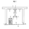
- FIG. 1 shows a crane 10. On the crane 10 stationary sensors 6 are mounted. Also shown is a cargo 12, for example a container on a truck, which is detected by the stationary sensors 6. Also in FIG. 1 To see wheels 14, with which the crane 10 can be moved on rails. A floor 15 under the crane 10 is inclined, so that water can flow away. On the floor 15 lane markers 13 are attached, which mark tracks for vehicles. On a trolley 4, a container harness 1 is suspended movably. The container harness 1 has Twistlocks 2, which can be used to grip containers.
- FIG. 2 shows a container harness 1 when approaching a container 10.
- twist locks 2 of the container harness 1 must be accurately positioned on standard corner fittings 11 of the container 10.
- FIG. 3 shows a container 10 when approaching a loading area 21 of a truck 20.
- corner fittings 11 of the container 10 must be accurately positioned over twist locks 2 of the truck 20.
- the container 10 is transported by means of a container harness 1 by a crane.
- FIG. 4 shows a container tableware 1, which is equipped with imaging sensors 3.
- the container harness 1 is deposited on a container 10.
- Suitable imaging sensors 3 are all sensors from whose measured values three-dimensional image data can be generated, for example laser scanners or strip projection sensors.
- An arithmetic unit forms three-dimensional image data from the measured values, from which position it determines anchoring positions, in particular positions of twistlocks or corner fittings.
- the anchorage positions need not be identical to the positions of the twistlocks, but may also be positions of structures that are easy to detect and whose relative position to the twistlock is known.
- the arithmetic unit calculates a target position for the container harness 1 from the anchoring positions. At the target position, the container harness 1 can, for example, pick up the container 10 or deposit it on a loading area of a truck or train wagon.
- the twistlocks and corner fittings appear in the three-dimensional image data with a typical 3D contour. This applies to the twistlock in both extended and contracted states.
- This type of position determination can take place once or continuously, as long as a Twistlock targeted by the imaging sensor 3 is not covered by the container 10. Under these conditions, the crane can be controlled in a control loop and move the container harness towards the target position. Once the sighted twistlock is obscured by the container 10, however, can The crane only the last piece to the target position controlled (blind) approach.
- Stationary sensors mounted on a bridge or trolley of the crane such as high overhead laser scanners or cameras, allow the approach to the target position to be accelerated by first placing the container harness in an appropriate coarse position or orientation position near the target position the imaging sensor 3 can detect a twistlock at the target position in its local field of view.
- this local field of view may be 0.5m x 0.5m so that the orientation position determined by the stationary sensors must approach the target position with that accuracy.
- the stationary sensors and possibly further distance sensors of the container harness 1 have to ensure that there is no collision when approaching the orientation position.
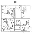
- FIG. 5 shows mounting positions of imaging sensors 3 on a container tableware 1 from different perspectives. Partly also Twistlocks 2 of the container harness 1 are visible.
- FIG. 6 1 shows a determination of measured values from an environment of a container harness 1.
- a container harness 1 On the left is a frontal view of the container harness 1 and a container 10 suspended thereon, and on the right a side view.
- a loading area 21 of a truck or train wagon is shown with a twistlock 2, which is located 4 m or 5 m below the container harness 1.
- An imaging sensor 3, here a simple camera, is mounted with 180mm or 150mm overhang against the container 10 on the container dishes 1.
- FIG. 6 It can be seen that the imaging sensor 3 can detect the twistlock 2 at 4 m or 5 m distance just in its field of view before the twistlock 2 is completely covered by the container 10.
- the height of the container 10 is assumed to be 2.960m.
- a line laser 30 is mounted on the front of the container harness 1 and illuminates the loading surface 21 at a known fixed angle to the vertical (the solder through the container harness 1) or to the loading surface 21 with a single laser line.
- the mounting position on the front of the container harness 1 makes the process independent of size changes of a telescopic frame of the container harness. From the illuminated by the laser line section through the camera image of the imaging sensor 3 three-dimensional data are calculated, for example, absolute metric three-dimensional data.
- the container harness is lowered from 5 meters above the loading area 21 to 4 meters height, as in FIG. 6 shown, wherein the laser line sweeps over the loading surface 21.
- the twistlock 2 is also covered. Consequently, a 3D contour of the twistlock 2 appears in the three-dimensional data. Based on the 3D contour, the twistlock 2 can be unambiguously identified independently of color, rust, rain, etc., since the 3D shape to be searched for is precisely known.
- FIG. 7 shows a laser line 31, which runs next to a twistlock 2.
- the laser line 31 is shown dotted for clarity, but can also be projected in reality as a solid line.
- FIG. 8 shows correspondingly a laser line 31, which passes over a twistlock 2, because, for example, as shown in FIG 6 describes the complete twistlock 2 swept over.
- the laser line 31 is shown dotted for clarity, but can also be projected in reality as a solid line.
- the imaging sensor for detecting the laser line 31 is, for example, a common camera, but which is preferably equipped with a band-pass filter adapted to the wavelength of the laser used.
- a band-pass filter adapted to the wavelength of the laser used.
- a particularly narrow band in conjunction with an LED with a narrow spectrum or a monochromatic laser diode is advantageous here.
- suitable lasers are corresponding LEDs or laser diodes, which in principle can emit other patterns than a line, for example a grating.
- an infrared laser or a red laser can be used.
- a good compromise for the observance of the laser protection determination with simultaneous high radiation density of the laser line 31 for the irradiation of the sunlight is achieved by a 20 ⁇ s line projection with a 1.35W laser diode.
- laser power a range of 200mW - 300mW is recommended.
- the imaging sensor in this case must be able to record images with an exposure time of only 20 ⁇ s. A black and white camera is sufficient for this. In pulsed operation, cooling for the laser may be omitted.
- a 3D sensor is mounted directly on the spreader (the container harness) and scans twistlocks or corner fittings of containers in the vicinity of the spreader. From this, the positions of the twistlocks can be calculated, whereby containers can be deposited fully automatically on the loading areas of trucks or train wagons.
- a particularly cost-effective and robust solution is the use of conventional cameras with a bandpass filter, which is tuned to the wavelength of a line laser and is used to filter the sunlight from the camera image. As the spreader approaches, the line laser passes over the cargo bed, allowing the 3D contours of the twistlocks to be extracted from the camera image.
- the problems of conventional image processing which are caused by different colors of twistlocks, pollution by rust and oil, weather, sunlight, etc., elegantly bypassed.
- the solution is suitable for cranes at container handling sites, but also for straddle carriers, gantry forklifts or forklifts.
Landscapes
- Engineering & Computer Science (AREA)
- Automation & Control Theory (AREA)
- Mechanical Engineering (AREA)
- Control And Safety Of Cranes (AREA)
- Length Measuring Devices By Optical Means (AREA)
Description
Im wachsenden Welthandel leistet die Container-Logistik erhebliche Beiträge. Sie zeichnet sich durch ständig wachsende Effizienz durch immer weitergehende Automatisierung aus. Viele Container-Umschlagplätze sind mithilfe von Kränen stark automatisiert.In growing global trade, container logistics make significant contributions. It is characterized by constantly increasing efficiency through more and more automation. Many container terminals are highly automated with the help of cranes.
Ladekrane werden auf Güterumschlagplätzen, Lagerplätzen, in Montagehallen und Werften sowie beim Gleisbau eingesetzt. Bei einem Ladekran für Kraftfahrzeuge ist der Boden gegenüber dem Ladekran geneigt, damit Wasser abfließen kann. Weiterhin sind auf dem Boden unter dem Ladekran Spuren für Lastwagen markiert. Eine Ausführung eines Ladekrans ist ein Portalkran. Dieser überspannt einen Lade- und Arbeitsbereich wie ein Portal. In der Regel laufen seine Seitenwände mit Rädern auf zwei parallelen Schienen. Auf der Kranbrücke, dem horizontalen Teil des Portalkrans, bewegt sich eine Laufkatze mit einem Hubwerk. Alternativ kann auch ein Schienendrehkran auf der Kranbrücke montiert sein. Weiterhin kommen als Ladekran auch ein Brückenkran, ein Halbportalkran, ein Bockkran sowie ein Portaldrehkran in Betracht.Loading cranes are used on freight transhipment sites, storage areas, in assembly halls and shipyards as well as in track construction. In a loading crane for motor vehicles, the floor is inclined relative to the loading crane, so that water can drain. Furthermore, tracks for trucks are marked on the ground under the loading crane. One embodiment of a loading crane is a gantry crane. This spans a loading and working area like a portal. As a rule, its sidewalls with wheels run on two parallel rails. On the crane bridge, the horizontal part of the gantry crane, a trolley moves with a hoist. Alternatively, a rail slewing crane can be mounted on the crane bridge. Furthermore come as a loading crane and a bridge crane, a half-gantry crane, a gantry crane and a portal crane into consideration.
Ein Containergeschirr (engl. Bezeichnung "Spreader") ist ein Hebezeug, mit welchem ISO-genormte Container ergriffen werden können. Es ist sowohl ein starres Containergeschirr bekannt, welches nur für eine Containergröße bestimmt ist, als auch ein teleskopierendes Containergeschirr, dessen mehrere Tonnen schwerer Teleskoprahmen flexibel auf die Länge unterschiedlicher normierter Container (Normgrößen 20'-45') eingestellt werden kann. Für die weitere Betrachtung ist vor allem die maximale Höhe eines "Highcube-"Containers von 2,896 m relevant.A container harness (English term "spreader") is a hoist, with which ISO-standardized containers can be taken. It is known both a rigid container dishes, which is intended only for a container size, as well as a telescoping container dishes whose several tons heavy telescopic frame can be flexibly adjusted to the length of different standardized containers (standard sizes 20'-45 '). For further consideration, the maximum height of a "high-cube" container of 2,896 m is especially relevant.
Auch Portalhubwagen, Portalstapler, Gabelstapler oder Quergabelstapler können mit einem Containergeschirr ausgerüstet werden. Das Containergeschirr ist auch hier ein Anbaugerät, dessen sogenannte Twistlocks in die vier oberen genormten Eckbeschläge eines Containers eingreifen oder die diesen von der Seite her greifen. Hierbei wird ein Element des Twistlocks um 90° rotiert, wodurch eine formschlüssige Verbindung zur Verriegelung gewährleistet ist. Die Größe der Twistlocks ist normiert und beträgt in etwa 104 mm in der Länge sowie 56 mm in der Breite.Gantry trucks, gantry forklifts, forklifts or cross-forklifts can also be equipped with a container harness. The container harness is also here an attachment whose so-called twist locks engage in the four upper standardized corner fittings of a container or grab them from the side. In this case, an element of the twistlock is rotated by 90 °, whereby a positive connection is ensured for locking. The size of the twistlocks is standardized and is about 104 mm in length and 56 mm in width.
Häufige Arbeitsvorgänge in der Container-Logistik sind das Verankern eines Containers am Containergeschirr, mit welchem der Container anschließend bewegt wird, sowie das Verankern der Container auf Bahnwaggons oder Ladeflächen von LKWs. Diese Aufgaben werden heute ausschließlich von Kranfahrern bewältigt, die teilweise an entfernten Stationen sitzen und unterschiedliche Kräne mithilfe von Videobildern bedienen.Frequent operations in container logistics involve anchoring a container to the container harness with which the container is subsequently moved, as well as anchoring the containers to rail wagons or loading areas of trucks. Today, these tasks are handled exclusively by crane operators, who sometimes sit at remote stations and operate different cranes with the help of video images.
Zur Verankerung eines Containers auf einer Ladefläche eines LKW oder Bahnwaggons kommen erneut Twistlocks zum Einsatz. Beim Aufsetzen des Containers müssen die genormten Eckbeschläge des Containers genau über den Twistlocks des LKW oder Bahnwaggons positioniert werden. Die erforderliche Genauigkeit für die Positionierung kann hierbei mit 25 mm abgeschätzt werden, wobei die Höhengenauigkeit weniger kritisch ist.To anchor a container on the back of a truck or train wagons Twistlocks are used again. When placing the container, the standardized corner fittings of the container must be positioned exactly above the twistlocks of the truck or train wagon. The required accuracy for the positioning can be estimated here with 25 mm, the height accuracy is less critical.
Aus dem Dokument "Kameragestützte Automatisierung von Containerkranen - Potentiale, Technologien, Rahmenbedingungen", Jörg Krüger und Mike Neuendorf, 19. Internationale Kran-Fachtagung 2011, ist eine kameragestützte, automatische Erkennung von Be- und Entladepositionen auf einem LKW bekannt. Diese Positionen werden aus den Bildern hochauflösender Kameras extrahiert, welche in großer Höhe an einer Laufkatze eines Containerkrans montiert sind. Hierbei werden in den Kamerabildern Eckbeschläge der Container sowie Twistlocks der LKW-Ladeflächen erkannt.From the document "Camera-Assisted Automation of Container Cranes - Potentials, Technologies, Framework Conditions", Jörg Krüger and Mike Neuendorf, 19th International Crane Conference 2011, a camera-based, automatic detection of loading and unloading positions on a truck is known. These positions are extracted from the images of high-resolution cameras mounted at height on a trolley of a container crane. This corner fittings of the container and Twistlocks the truck beds are detected in the camera images.
Aus dem Dokument "Container handlers" erhältlich im Internet unter http://www.orlaco.com/container-handlers.htm am 29.09.2011, ist bekannt, direkt am Containergeschirr Kameras zu montieren, deren Bilder einem Fahrer eines Gabelstaplers erleichtern, das Containergeschirr an einem Container zu verankern.From the document "container handlers" available on the Internet under http://www.orlaco.com/container-handlers.htm on 29.09.2011, it is known to mount cameras directly on the container harness, whose images facilitate a driver of a forklift, the To anchor container harness to a container.
Aus der
Aus der
Es stellt sich die Aufgabe, ein Verfahren zur Bestimmung einer Zielposition für ein Containergeschirr sowie ein Containergeschirr anzugeben, mit welchen die häufigen Verankerungsvorgänge von Containern besser unterstützt werden.The object is to provide a method for determining a target position for a container harness and a container dishes, with which the frequent anchoring operations of containers are better supported.
Diese Aufgabe wird durch das Verfahren zur Bestimmung einer Zielposition für ein Containergeschirr gelöst, wobei mindestens ein bildgebender Sensor an dem Containergeschirr montiert ist und Messwerte von einer Umgebung des Containergeschirrs ermittelt. Der mindestens eine bildgebende Sensor ist eine Kamera. Eine Recheneinheit bildet aus den Messwerten dreidimensionale Daten, aus welchen sie Verankerungs-Positionen, insbesondere Positionen von Twistlocks oder Eckbeschlägen, ermittelt, und berechnet aus den Verankerungs-Positionen die Zielposition für das Containergeschirr. Das Containergeschirr ist zusätzlich mit mindestens einem Laser ausgerüstet.This object is achieved by the method for determining a target position for a container harness, wherein at least one imaging sensor is mounted on the container harness and determines measured values from an environment of the container harness. The at least one imaging sensor is a camera. An arithmetic unit forms three-dimensional data from the measured values, from which it determines anchoring positions, in particular positions of twistlocks or corner fittings, and calculates the target position for the container harness from the anchoring positions. The container harness is additionally equipped with at least one laser.
Das Verfahren ist dadurch gekennzeichnet, dass die Recheneinheit aus den Messwerten Linien extrahiert, welche der Laser auf ein Twistlock oder einen Eckbeschlag projiziert. Die Recheneinheit ermittelt aus einer Geometrie der Linien die Verankerungs-Positionen.The method is characterized in that the arithmetic unit extracts lines from the measured values, which the laser projects onto a twistlock or a corner fitting. The arithmetic unit determines the anchoring positions from a geometry of the lines.
Das Containergeschirr ist mit mindestens einem bildgebenden Sensor ausgerüstet, welcher an dem Containergeschirr montiert und zur Ermittlung v5on Messwerten von einer Umgebung des Containergeschirrs eingerichtet ist. Der bildgebende Sensor ist eine Kamera und zur Ermittlung von Messwerten geeignet und eingerichtet, aus welchen dreidimensionale Daten berechenbar sind, aus welchen wiederum Verankerungs-Positionen, insbesondere Positionen von Twistlocks oder Eckbeschlägen, ermittelbar sind.The container harness is equipped with at least one imaging sensor which is mounted on the container harness and adapted to determine measurements from an environment of the container harness. The imaging sensor is a camera and suitable for determining measured values and set up, from which three-dimensional data can be calculated, from which in turn anchoring positions, in particular positions of twistlocks or corner fittings, can be determined.
Das Containergeschirr ist durch einen Linienlaser gekennzeichnet, welcher in einem definierten Abstand zu dem mindestens einen bildgebenden Sensor am Containergeschirr montiert ist und eine Laserlinie in einem definierten Winkel zu einer Senkrechten abstrahlt.The container harness is characterized by a line laser, which is mounted at a defined distance from the at least one imaging sensor on the container and dishes a laser line at a defined angle to a vertical.
Das Verfahren sowie das Containergeschirr stellen eine zuverlässige Lösung zur automatisierten Positionierung des Containergeschirrs bereit. Die Genauigkeit ist aufgrund der dreidimensionalen Datenverarbeitung so hoch, dass nach erfolgter Positionierung Twistlocks automatisch in Eckbeschlägen eines Container verriegelt werden können. Dies erlaubt das automatisierte Beladen von LKWs für den Straßenverkehr oder Bahnwaggons, bei denen die zu transportierenden Container mit Twistlocks auf der Ladefläche gesichert werden müssen. Die Positionierung des bildgebenden Sensors am Containergeschirr erzielt aufgrund der Nähe zu den zu erkennenden Objekten eine hohe Genauigkeit und in der Folge eine hohe Zuverlässigkeit bei der Positionierung. Letztere ist unerlässlich, um Sach- und Personenschäden zu vermeiden. So wird es erstmals möglich, das Be- und Entladen von Fahrzeugen mit Twistlock-Sicherung zu automatisieren.The method as well as the container harness provide a reliable solution for the automated positioning of the container harness. Due to the three-dimensional data processing, the accuracy is so high that after positioning, twistlocks can automatically be locked in corner fittings of a container. This allows the automated loading of trucks for road traffic or rail cars, in which the container to be transported must be secured with twist locks on the bed. The positioning of the imaging sensor on the container dishes achieved due to the proximity to the objects to be detected high accuracy and consequently high reliability in positioning. The latter is essential to avoid property damage and personal injury. This is how it becomes possible for the first time to automate the loading and unloading of vehicles with twistlock securing.
Das Verfahren hat den Vorteil, dass die Linien, welche der Laser auf das Twistlock oder den Eckbeschlag projiziert, auch im Freien bei ungünstigen Witterungsbedingen wie Regen, direkter tropischer Sonneneinstrahlung oder Verschmutzung durch Rost oder Öl, einen hinreichenden Kontrast erzeugen, welcher durch die Kamera detektiert wird und die Extraktion der Linien aus den Messwerten gewährleistet. Es wird eine sehr robuste Positionserkennung erzielt.The method has the advantage that the lines which the laser projects onto the twistlock or the corner fitting produce a sufficient contrast even in the open air in unfavorable weather conditions such as rain, direct tropical solar radiation or contamination by rust or oil, which is detected by the camera and the extraction of the lines from the measured values is ensured. It is achieved a very robust position detection.
Weiterhin bietet der Einsatz einer einfachen Kamera den Vorteil, dass diese in robuster Ausführung gewählt werden kann, wodurch die in Anbetracht der heftigen Erschütterungen am Kran und insbesondere am Containergeschirr erforderliche mechanische Stabilität gewährleistet wird. Auch kann bei diesen einfachen und kostengünstigen Komponenten mit einer langen Lebensdauer gerechnet werden. Dies ist von Vorteil, da ein häufiger Komponentenwechsel mit Nachkalibrierung im industriellen Einsatz nicht in Frage kommt.Furthermore, the use of a simple camera has the advantage that it can be selected in a robust design, whereby the required in view of the violent vibrations on the crane and in particular on the container harness mechanical stability is ensured. Also can be expected in these simple and inexpensive components with a long life. This is advantageous because a frequent component change with recalibration in industrial use is out of the question.
In einer Weiterbildung des Verfahrens ist der Laser ein Linienlaser, welcher in einem definierten Abstand zu dem mindestens einen bildgebenden Sensor am Containergeschirr montiert ist und eine Laserlinie in einem definierten Winkel zu einer Senkrechten abstrahlt. Das Containergeschirr wird über mindestens einem Twistlock oder Eckbeschlag zumindest teilweise abgesenkt, wobei die Laserlinie das Twistlock oder den Eckbeschlag überstreicht. Die Recheneinheit extrahiert die Laserlinie fortlaufend aus den Messwerten und ermittelt aus der Geometrie der Laserlinie als dreidimensionale Daten eine 3D-Kontur. Anhand der 3D-Kontur erkennt die Recheneinheit das Twistlock oder den Eckbeschlag.In a development of the method, the laser is a line laser, which is mounted at a defined distance from the at least one imaging sensor on the container harness and emits a laser line at a defined angle to a vertical. The container harness is at least partially lowered via at least one twistlock or corner fitting, with the laser line sweeping over the twistlock or corner fitting. The arithmetic unit continuously extracts the laser line from the measured values and determines a 3D contour from the geometry of the laser line as three-dimensional data. Based on the 3D contour, the arithmetic unit recognizes the twistlock or the corner fitting.
Diese Weiterbildung hat den Vorteil, dass der Linienlaser fest am Containergeschirr montiert wird und keine dreh- oder schwenkbare Aufhängung benötigt. Auch kann der Linienlaser selbst in robuster Ausführung gewählt werden. Beide Aspekte tragen den industriellen Anforderungen an die Robustheit der Sensorik Rechnung.This development has the advantage that the line laser is firmly mounted on the container harness and no turning or swivel suspension needed. Also, the line laser itself can be selected in robust design. Both aspects take into account the industrial requirements for the robustness of the sensors.
Gemäß einer Ausführungsform berechnet die Recheneinheit zur Extraktion der Laserlinie aus den Messwerten ein Differenzbild, welches aus der Differenz eines Kamerabilds mit der Laserlinie mit einem zeitnahen Kamerabild ohne die Laserlinie gebildet wird.According to one embodiment, the arithmetic unit calculates a difference image, which consists of the difference of a camera image with the laser line, for extracting the laser line from the measured values is formed with a timely camera image without the laser line.
Die Berechnung eines Differenzbildes bietet den Vorteil, dass als Störfaktoren a priori unbekannte Veränderungen des Hintergrunds durch wechselnde Lichtverhältnisse, Rost, Verschmutzung o.ä. ausgeschaltet werden können, wodurch die Robustheit der Erkennung deutlich erhöht wird.The calculation of a difference image offers the advantage that interference factors a priori unknown changes in the background due to changing lighting conditions, rust, contamination o.ä. can be turned off, whereby the robustness of the detection is significantly increased.
In einer Weiterbildung ist die Kamera mit einem an eine Wellenlänge des Lasers angepassten Bandpassfilter ausgerüstet. Der Bandpassfilter erhöht die Robustheit der Bilderkennung bei Sonnenlicht, da alle Wellenlängen des Sonnenlichts außerhalb der Wellenlängen des Lasers gefiltert und somit als Störfaktoren im Kamerabild ausgeschaltet werden.In a further development, the camera is equipped with a bandpass filter adapted to a wavelength of the laser. The bandpass filter increases the robustness of image recognition in sunlight, since all wavelengths of sunlight are filtered out of the wavelengths of the laser and thus turned off as disturbing factors in the camera image.
Gemäß einer Ausführungsform wird das Containergeschirr an der Zielposition vollautomatisch an einem Container verankert, indem Twistlocks des Containergeschirrs in Eckbeschläge des Containers eingreifen und sich verriegeln.According to one embodiment, the container harness at the target position is fully automatically anchored to a container by twist locks of the container harness engage and lock in corner fittings of the container.
Bei einer alternativen Ausführungsform wird ein an dem Containergeschirr verankerter Container an der Zielposition vollautomatisch auf einer Ladefläche eines LKW oder Bahnwaggons verankert wird, indem Twistlocks des LKW oder Bahnwaggons in Eckbeschläge des Containers eingreifen und sich verriegeln.In an alternative embodiment, a container anchored to the container harness at the target position is fully automatically anchored to a cargo bed of a truck or railroad car by engaging twist locks of the truck or railcar in corner fittings of the container and locking.
In einer Weiterbildung wird das Containergeschirr in die Zielposition bewegt, wobei zwei Bewegungsabschnitte durchlaufen werden. Im ersten Bewegungsabschnitt besteht ein Sichtkontakt zwischen mindestens einer Verankerungs-Position und dem bildgebenden Sensor besteht. Weiterhin erfolgt im ersten Bewegungsabschnitt in einer Regelschleife eine fortlaufende Neuberechnung der Zielposition. Im zweiten Bewegungsabschnitt besteht kein Sichtkontakt zwischen den Verankerungs-Positionen und dem bildgebenden Sensor. Daher wird die zuletzt berechnete Zielposition im zweiten Bewegungsabschnitt gesteuert angefahren.In a development, the container harness is moved to the target position, wherein two movement sections are traversed. In the first movement section, there is visual contact between at least one anchoring position and the imaging sensor. Furthermore, in the first movement section in a control loop, a continuous recalculation of the target position takes place. In the second movement section, there is no visual contact between the anchoring positions and the imaging sensor. Therefore, the last one becomes calculated target position in the second movement section controlled approached.
Diese Weiterbildung trägt der Tatsache Rechnung, dass die Twistlocks im zweiten Bewegungsabschnitt durch den Container selbst verdeckt sein können. Durch die Weiterbildung kann die Zielposition auch in dieser Situation angenähert werden.This development takes into account the fact that the twist locks in the second movement section can be covered by the container itself. Through the training, the target position can be approximated in this situation.
Gemäß einer Ausführungsform ermittelt mindestens ein stationärer Sensor Orientierungs-Messwerte von einer Umgebung des Containergeschirrs ermittelt. Eine Recheneinheit ermittelt aus den Orientierungs-Messwerten eine Orientierungs-Position für das Containergeschirr, welche sich in der Nähe der Zielposition befindet. Das Containergeschirr wird in die Orientierungs-Position manövriert, bevor die Zielposition bestimmt wird. Diese Ausführungsform beschleunigt den Vorgang, indem das Containergeschirr mithilfe der stationären Sensoren vorab zeitsparend in die Orientierungs-Position gebracht wird.According to one embodiment, at least one stationary sensor determines orientation measured values of an environment of the container harness. An arithmetic unit determines from the orientation measured values an orientation position for the container harness, which is located in the vicinity of the target position. The container harness is maneuvered to the orienting position before the target position is determined. This embodiment speeds up the process by bringing the container harness using the stationary sensors in advance to save time in the orientation position.
In einer Weiterbildung ist das Containergeschirr mit weiteren Sensoren, insbesondere 2D-Laserscannern, 3D-Laserscannern, Kameras, 3D-Kameras, Streifenprojektionssensoren, Abstandssensoren, Näherungsschaltern und/oder Druckschaltern ausgerüstet. Dies ermöglicht eine weitere Steigerung der Genauigkeit der Positionsbestimmung sowie zusätzliche Sicherheit im Betrieb.In a further development, the container harness is equipped with further sensors, in particular 2D laser scanners, 3D laser scanners, cameras, 3D cameras, strip projection sensors, distance sensors, proximity switches and / or pressure switches. This allows a further increase in the accuracy of the position determination and additional safety during operation.
Ein Kran ist ausgebildet als Ladekran, Portalkran, Brückenkran, Halbportalkran, Bockkran oder Portaldrehkran, und mit dem Containergeschirr ausgerüstet.A crane is designed as a loading crane, gantry crane, bridge crane, semi-portal crane, gantry crane or portal crane, and equipped with the container harness.
In einer Weiterbildung ist der Kran zusätzlich mit stationären Sensoren, insbesondere Kameras und/oder Laserscanner, welche am Kran montiert sind, ausgerüstet.In a development, the crane is additionally equipped with stationary sensors, in particular cameras and / or laser scanners, which are mounted on the crane.
Die stationären Sensoren dienen zur Messung (bzw. Schätzung) der Position und Lage beweglicher Objekte, z.B. eines Containers. Als weitere Verwendungen kommen die Messung der Position und Lage eines Fahrzeugs oder eines beweglichen Bauteils des Krans selbst in Betracht. Im Kontext eines Ladekrans dienen die Messungen der stationären Sensoren als Grundlage, um LKW-Fahrern zu signalisieren, wo sie anzuhalten haben. Weiterhin kann aufgrund solcher Messungen der Kran selbst gesteuert werden.The stationary sensors serve to measure (or estimate) the position and position of moving objects, eg a container. Other uses include measuring the position and position of a vehicle or a movable component of the crane itself into consideration. In the context of a loading crane, stationary sensor measurements serve as a basis to signal truck drivers where to stop. Furthermore, due to such measurements, the crane itself can be controlled.
Die stationären Sensoren können beispielsweise aus einem oder mehreren der folgenden Elemente zusammengesetzt sein: einem 3D-Laserscanner, einem schwenkbaren 2D-Laserscanner oder einer Videokamera. Sie werden üblicherweise derart im Tragwerk des Krans angebracht, dass - im Falle eines Portalkrans - mehrere Spuren für LKW oder Gleise für Eisenbahnwaggons überstrichen werden.The stationary sensors may for example be composed of one or more of the following elements: a 3D laser scanner, a tiltable 2D laser scanner or a video camera. They are usually mounted in such a way in the structure of the crane that - in the case of a gantry crane - several tracks for trucks or tracks for railroad cars are covered.
Das Flurförderzeug ist als Portalhubwagen, Portalstapler, Gabelstapler oder Quergabelstapler ausgeführt und mit einem Containergeschirr nach einem der Ansprüche 11 bis 16 ausgerüstet.The truck is designed as a straddle carrier, portal stacker, forklift or forklift truck and equipped with a container harness according to one of
Auf dem computerlesbaren Datenträger ist ein Computerprogramm gespeichert, welches das Verfahren ausführt, wenn es in einem Computer abgearbeitet wird. Das Computerprogramm wird in einem Computer abgearbeitet und führt dabei das Verfahren aus.The computer-readable medium stores a computer program which executes the procedure when it is executed in a computer. The computer program is processed in a computer and executes the procedure.
Im Folgenden werden Ausführungsbeispiele der Erfindung anhand von Figuren näher erläutert. Es zeigen:
Figur 1- einen Kran mit stationären Sensoren sowie ein Frachtgut unter dem Kran,
Figur 2- ein Containergeschirr bei der Annäherung an einen Container,
Figur 3- einen Container bei der Annäherung an einen LKW,
Figur 4- ein Containergeschirr, welches mit bildgebenden Sensoren ausgerüstet ist,
Figur 5- Montagepositionen der bildgebenden Sensoren,
Figur 6- eine Ermittlung von Messwerten von einer Umgebung eines Containergeschirrs,
- Figur 7
- eine Laserlinie, welche neben einem Twistlock verläuft, und
- Figur 8
- eine Laserlinie, welche über ein Twistlock verläuft.
- FIG. 1
- a crane with stationary sensors and a cargo under the crane,
- FIG. 2
- a container harness when approaching a container,
- FIG. 3
- a container approaching a truck,
- FIG. 4
- a container harness equipped with imaging sensors,
- FIG. 5
- Mounting positions of the imaging sensors,
- FIG. 6
- a determination of measured values from an environment of a container harness,
- FIG. 7
- a laser line that runs next to a twistlock, and
- FIG. 8
- a laser line, which runs over a twistlock.
Als bildgebende Sensoren 3 eignen sich alle Sensoren, aus deren Messwerten sich dreidimensionale Bilddaten erzeugen lassen, beispielsweise Laserscanner oder Streifenprojektionssensoren.
Werden als bildgebende Sensoren 3 lediglich einfache Kameras eingesetzt, so ist eine zuverlässige Erkennung der Twistlocks durch die Vielfalt der Erscheinungsformen von Ladeflächen und Twistlocks, welche sich durch Farbe, Rost, Dreck, Witterung etc. voneinander abweichen, allein anhand des Kamerabildes technologisch sehr schwierig. Diese Hürde wird durch die Erzeugung dreidimensionaler Bilddaten überwunden.If only simple cameras are used as
Eine Recheneinheit, beispielsweise ein Mikroprozessor, bildet aus den Messwerten dreidimensionale Bilddaten, aus welchen sie Verankerungs-Positionen, insbesondere Positionen von Twistlocks oder Eckbeschlägen, ermittelt. Die Verankerungs-Positionen müssen jedoch nicht mit den Positionen der Twistlocks identisch sein, sondern dürfen auch Positionen von Strukturen sein, die sich leicht ermitteln lassen und deren Relativposition zum Twistlock bekannt ist. Ferner berechnet die Recheneinheit aus den Verankerungs-Positionen eine Zielposition für das Containergeschirr 1. An der Zielposition kann das Containergeschirr 1 beispielsweise den Container 10 aufnehmen oder auf einer Ladefläche eines LKW oder Bahnwaggons absetzen. Die Twistlocks und Eckbeschläge erscheinen in den dreidimensionalen Bilddaten mit einer typischen 3D-Kontur. Dies gilt für das Twistlock sowohl im ausgefahrenen als auch im eingezogenen Zustand.An arithmetic unit, for example a microprocessor, forms three-dimensional image data from the measured values, from which position it determines anchoring positions, in particular positions of twistlocks or corner fittings. However, the anchorage positions need not be identical to the positions of the twistlocks, but may also be positions of structures that are easy to detect and whose relative position to the twistlock is known. Furthermore, the arithmetic unit calculates a target position for the
Diese Art der Positionsbestimmung kann einmalig oder auch fortlaufend erfolgen, solange ein durch den bildgebenden Sensor 3 anvisiertes Twistlock nicht vom Container 10 verdeckt wird. Unter diesen Voraussetzungen kann der Kran in einer Regelschleife angesteuert werden und das Containergeschirr in Richtung der Zielposition bewegen. Sobald das anvisierte Twistlock durch den Container 10 jedoch verdeckt wird, kann der Kran das letzte Stück bis zur Zielposition lediglich gesteuert (blind) anfahren.This type of position determination can take place once or continuously, as long as a Twistlock targeted by the
Stationäre Sensoren, welche an einer Brücke oder Laufkatze des Krans montiert sind, beispielsweise hoch hängende Laserscanner oder Kameras, erlauben es, die Anfahrt der Zielposition zu beschleunigen, indem sie das Containergeschirr zunächst in eine geeignete Grobposition oder Orientierungsposition in der Nähe der Zielposition bringen, an der der bildgebenden Sensors 3 ein Twistlock an der Zielposition in seinem lokalen Blickfeld erfassen kann. Dieses lokale Blickfeld kann beispielsweise 0,5m x 0,5m betragen, sodass die Orientierungsposition, welche die stationären Sensoren bestimmen, die Zielposition mit dieser Genauigkeit annähern muss. Auch haben die stationären Sensoren sowie ggf. weitere Abstandssensoren des Containergeschirrs 1 dafür Sorge zu tragen, dass es bei der Anfahrt der Orientierungsposition zu keine Kollision kommt.Stationary sensors mounted on a bridge or trolley of the crane, such as high overhead laser scanners or cameras, allow the approach to the target position to be accelerated by first placing the container harness in an appropriate coarse position or orientation position near the target position the
Um sicherzustellen, dass mindestens zwei Twistlocks visuell erfasst werden können, wenn die bildgebenden Sensoren 3 an allen vier Ecken des Containergeschirrs 1 angeordnet sind, empfiehlt es sich, die Orientierungsposition etwas dezentriert zur vermuteten Zielposition zu wählen.To ensure that at least two twistlocks can be visually detected when the
Im vorliegenden Ausführungsbeispiel ist ein Linienlaser 30 an der Front des Containergeschirrs 1 montiert und beleuchtet die Ladefläche 21 unter einem bekannten festen Winkel zur Senkrechten (dem Lot durch das Containergeschirr 1) bzw. zur Ladefläche 21 mit einer einzelnen Laserlinie. Die Montageposition an der Front des Containergeschirrs 1 macht das Verfahren unabhängig von Größenänderungen eines Teleskoprahmens des Containergeschirrs. Aus dem von der Laserlinie beleuchteten Schnitt durch das Kamerabild des bildgebenden Sensors 3 werden dreidimensionale Daten berechnet, beispielsweise absolute metrische dreidimensionale Daten.In the present embodiment, a line laser 30 is mounted on the front of the
Hierzu wird das Containergeschirr aus 5 Metern Höhe über der Ladefläche 21 auf 4 Meter Höhe abgesenkt, wie in
Der bildgebende Sensor zur Erfassung der Laserlinie 31 ist beispielsweise eine gewöhnliche Kamera, welche jedoch vorzugsweise mit einem Bandpassfilter ausgerüstet ist, der an die Wellenlänge des verwendeten Lasers angepasst ist. Hierdurch wird die Robustheit der Bildverarbeitung gegenüber dem Störfaktor Sonnenlicht deutlich erhöht. Ein besonders schmales Band in Verbindung mit einer LED mit einem schmalen Spektrum oder einer monochromatischen Laserdiode ist hierbei von Vorteil. Als Laser eignen sich folglich entsprechende LEDs oder Laserdioden, die grundsätzlich auch andere Muster als eine Linie, beispielsweise ein Gitter abstrahlen können. Beispielsweise kann ein Infrarotlaser oder ein roter Laser verwendet werden. Zur Einhaltung der Laserschutzbestimmungen für das menschliche Auge empfiehlt es sich, die Bestrahlungszeiten des Lasers auf einen Bereich von jeweils einigen zehn Mikrosekunden zu reduzieren.The imaging sensor for detecting the
Ein guter Kompromiss zur Einhaltung der Laserschutzbestimmung bei gleichzeitig hoher Strahlungsdichte der Laserlinie 31 zur Überstrahlung des Sonnenlichts wird durch eine 20µs Linienprojektion mit einer 1,35W Laserdiode erzielt. Als Laserleistung empfiehlt sich ein Bereich von 200mW - 300mW. Der bildgebende Sensor muss in diesem Fall in der Lage sein, Bilder mit einer Belichtungszeit von lediglich 20µs aufzuzeichnen. Eine Schwarz-Weiß-Kamera ist hierzu ausreichend. Im Pulsbetrieb kann eine Kühlung für den Laser ggf. entfallen.A good compromise for the observance of the laser protection determination with simultaneous high radiation density of the
Zur Fokussierung der Laserlinie 31 bieten sich bei Verwendung einer Laserdiode Powell-Linsen oder Zylinderlinsen an, um eine möglichst schmale Laserlinie 31 zu erzielen, welche über einen relativ weiten Tiefenbereich von 0,5m - 1,2m scharf abgebildet wird.To focus the
Um einen ausreichenden Kontrast der Laserlinie 31 vor dem Bildhintergrund auch bei direktem Einfall von Sonnenlicht sicherzustellen, bietet es sich an, ein Differenzbild zu erzeugen. Hierzu werden von der zu vermessenden Oberfläche unmittelbar aufeinander folgend zwei Bilder erfasst, wobei das eine Bild mit und das andere Bild ohne die Laserlinie 31 aufgenommen wird. Die Differenz beider Bilder bringt die Laserlinie 31 besonders deutlich hervor, indem sie den Einfluss von Umgebungslicht und anderen störenden Strukturen im Bild beseitigt. Anschließend empfiehlt es sich, den Grauwertbereich des Bildes zu dehnen.In order to ensure a sufficient contrast of the
Ein 3D-Sensor wird direkt am Spreader (dem Containergeschirr) montiert und tastet Twistlocks bzw. Eckbeschläge von Containern in der Umgebung des Spreaders ab. Hieraus lassen sich die Positionen der Twistlocks berechnen, wodurch sich Container vollautomatisch auf Ladeflächen von LKW oder Bahnwaggons absetzen lassen. Als besonders kostengünstige und robuste Lösung eignet sich der Einsatz herkömmlicher Kameras mit einem Bandpassfilter, welcher auf die Wellenlänge eines Linienlasers abgestimmt ist und zur Filterung der Sonneneinstrahlung aus dem Kamerabild dient. Der Linienlaser überstreicht bei der Annäherung des Spreaders die Ladefläche, wodurch sich 3D-Konturen der Twistlocks aus dem Kamerabild extrahieren lassen. Hierbei werden die Probleme herkömmlicher Bildverarbeitung, welche durch unterschiedliche Farben der Twistlocks, Verschmutzung durch Rost und Öl, Witterung, Sonneneinstrahlung etc. hervorgerufen werden, elegant umgangen. Die Lösung eignet sich für Kräne an Containerumschlagplätzen, aber auch für Portalhubwagen, Portalstapler oder Gabelstapler.A 3D sensor is mounted directly on the spreader (the container harness) and scans twistlocks or corner fittings of containers in the vicinity of the spreader. From this, the positions of the twistlocks can be calculated, whereby containers can be deposited fully automatically on the loading areas of trucks or train wagons. A particularly cost-effective and robust solution is the use of conventional cameras with a bandpass filter, which is tuned to the wavelength of a line laser and is used to filter the sunlight from the camera image. As the spreader approaches, the line laser passes over the cargo bed, allowing the 3D contours of the twistlocks to be extracted from the camera image. Here, the problems of conventional image processing, which are caused by different colors of twistlocks, pollution by rust and oil, weather, sunlight, etc., elegantly bypassed. The solution is suitable for cranes at container handling sites, but also for straddle carriers, gantry forklifts or forklifts.
Die beschriebenen Ausführungsbeispiele, Weiterbildungen und Ausführungformen lassen sich frei miteinander kombinieren.The described embodiments, developments and embodiments can be freely combined with each other.
Claims (15)
- Method for determining a target position for a container spreader (1), at least one imaging sensor (3) being mounted on the container spreader (1) and determining measured values from the surroundings of the container spreader (1),- in which the at least one imaging sensor (3) is a camera,- in which a computing unit uses the measured values to form three-dimensional data, from which it determines anchoring positions, in particular positions of twist locks (2) or corner fittings (11),- in which the computing unit uses the anchoring positions to calculate the target position for the container spreader (1), and- in which the container spreader (1) is additionally equipped with at least one laser,characterized in that- the computing unit extracts lines from the measured values, which lines the laser projects onto a twist lock (2) or a corner fitting (11), and- the computing unit determines the anchoring positions from a geometry of the lines.
- Method according to Claim 1,- in which the laser is a linear laser (30), which is mounted on the container spreader (1) at a defined distance from the at least one imaging sensor (3), and emits a laser line (31) at a defined angle to a vertical,- in which the container spreader (1) is at least partly lowered over at least one twist lock (2) or corner fitting (11), the laser line (31) sweeping over the twist lock (2) or the corner fitting (11),- in which the computing unit continuously extracts the laser line (31) from the measured values and determines a 3-D contour as three-dimensional data from the geometry of the laser line (31), and- in which the computing unit detects the twist lock (2) or the corner fitting (11) by using the 3-D contour.
- Method according to Claim 2,- in which the computing unit for extracting the laser line (31) from the measured values calculates a differential image, which is formed from the difference between a camera image with the laser line (31) and a contemporary camera image without the laser line (31).
- Method according to one of the preceding claims,- in which the container spreader (1) is fully automatically anchored on a container (10) at the target position, by twist locks (2) of the container spreader (1) engaging in corner fittings (11) of the container (10) and being locked.
- Method according to one of Claims 1 to 3,- in which a container (10) anchored to the container spreader (1) at the target position is fully automatically anchored on a loading surface of an LGV (20) or railway wagon, by twist locks (2) of the LGV (20) or railway wagon engaging in corner fittings (11) of the container (10) and being locked.
- Method according to one of the preceding claims,- in which the container spreader (1) is moved into the target position, two movement sections being passed through,- in which, in the first movement section, there is a visual contact between at least one anchoring position and the imaging sensor (3),- in which, in the first movement section, continuous recalculation of the target position is carried out in a control loop,- in which, in the second movement section, there is no visual contact between the anchoring positions and the imaging sensor (3), and- in which, in the second movement section, the last calculated target position is approached under control.
- Method according to one of the preceding claims, in which- at least one stationary sensor (6) determines orientation measured values from the surroundings of the container spreader (1),- a computing unit uses the orientation measured values to determine an orientation position for the container spreader (1), which is located in the vicinity of the target position, and- in which the container spreader (1) is manoeuvred into the orientation position before the target position is determined.
- Container spreader (1),- equipped with at least one imaging sensor (3), which is mounted on the container spreader (1) and is set up to determine measured values from the surroundings of the container spreader (1),- wherein the at least one imaging sensor (3) is a camera and is suitable and set up to determine measured values, from which three-dimensional data can be calculated, from which in turn anchoring positions, in particular positions of twist locks (2) or corner fittings (11), can be determined,characterized in that- the container spreader is additionally equipped with a linear laser (30), which is mounted on the container spreader (1) at a defined distance from the at least one imaging sensor (3) and emits a laser line (31) at a defined angle to a vertical.
- Container spreader (1) according to Claim 8,- in which the camera is equipped with a band-pass filter matched to a wavelength of the laser.
- Container spreader (1) according to either of Claims 8 and 9,- equipped with further sensors, in particular 2-D laser scanners, 3-D laser scanners, cameras, 3-D cameras, stripe projection sensors, distance sensors, proximity switches and/or pressure switches.
- Crane (5),- constructed as a loading crane, portal crane, bridge crane, semi-portal crane, gantry crane or slewing portal crane, and- equipped with a container spreader (1) according to one of Claims 8 to 10.
- Crane (5) according to Claim 11,- additionally equipped with stationary sensors (6), in particular cameras and/or laser scanners, which are mounted on the crane (5).
- Industrial truck- implemented as a straddle carrier, portal stacker, fork-lift truck or side-loader, and- equipped with a container spreader (1) according to one of Claims 8 to 10.
- Computer-readable data storage medium,- on which there is stored a computer program which carries out the method according to one of Claims 1 to 7 when it is executed in a computer.
- Computer program,- which is executed in a computer and carries out the method according to one of Claims 1 to 7.
Priority Applications (2)
| Application Number | Priority Date | Filing Date | Title |
|---|---|---|---|
| EP11183486.7A EP2574587B1 (en) | 2011-09-30 | 2011-09-30 | Method for determining a target position for a container spreader and the container spreader |
| CN201210369772.3A CN103030063B (en) | 2011-09-30 | 2012-09-29 | For determining method and the container spreader of target position for container spreader |
Applications Claiming Priority (1)
| Application Number | Priority Date | Filing Date | Title |
|---|---|---|---|
| EP11183486.7A EP2574587B1 (en) | 2011-09-30 | 2011-09-30 | Method for determining a target position for a container spreader and the container spreader |
Publications (2)
| Publication Number | Publication Date |
|---|---|
| EP2574587A1 EP2574587A1 (en) | 2013-04-03 |
| EP2574587B1 true EP2574587B1 (en) | 2014-06-25 |
Family
ID=44719619
Family Applications (1)
| Application Number | Title | Priority Date | Filing Date |
|---|---|---|---|
| EP11183486.7A Active EP2574587B1 (en) | 2011-09-30 | 2011-09-30 | Method for determining a target position for a container spreader and the container spreader |
Country Status (2)
| Country | Link |
|---|---|
| EP (1) | EP2574587B1 (en) |
| CN (1) | CN103030063B (en) |
Cited By (3)
| Publication number | Priority date | Publication date | Assignee | Title |
|---|---|---|---|---|
| CN106794971A (en) * | 2014-06-30 | 2017-05-31 | 科尼全球公司 | Transported by the load for loading processing equipment |
| WO2018224408A1 (en) | 2017-06-08 | 2018-12-13 | Konecranes Global Corporation | Automatically guided lifting gantry device for containers and method for operating such a lifting gantry device |
| US11873195B2 (en) | 2017-11-24 | 2024-01-16 | Tmeic Corporation | Methods and systems for generating landing solutions for containers on landing surfaces |
Families Citing this family (20)
| Publication number | Priority date | Publication date | Assignee | Title |
|---|---|---|---|---|
| DE102012020953B4 (en) * | 2012-10-25 | 2016-03-10 | LASE Industrielle Lasertechnik GmbH | 3D laser scan measuring system for determining the position in which an ISO container is to be placed on a carrier vehicle |
| DE102013011718A1 (en) | 2013-07-15 | 2015-01-15 | Isam Ag | Method for controlling a container bridge for loading or unloading, in particular of the loading space, of a ship or control system for controlling a container bridge or container bridge with control system |
| CN103613015B (en) * | 2013-11-26 | 2015-08-26 | 中联重科股份有限公司 | Safety jaw carries control method, device, system and hoisting crane |
| ES2627498T3 (en) | 2014-09-24 | 2017-07-28 | Siemens Aktiengesellschaft | Method for automatic, optical determination of an objective position for a container lifting device |
| FI127606B (en) | 2015-04-01 | 2018-10-15 | Konecranes Oyj | Method, load handling device, computer program and computer program product for positioning gripping means |
| CN105512607B (en) * | 2015-11-25 | 2019-01-15 | 浙江工业大学 | A kind of truck tapered end location recognition method |
| CN105480848A (en) * | 2015-12-21 | 2016-04-13 | 上海新时达电气股份有限公司 | Port crane lifting system and stacking method thereof |
| TWI582036B (en) * | 2016-05-05 | 2017-05-11 | 中國鋼鐵股份有限公司 | Storage space identification system of automatic crane and storage space identification method thereof |
| CN105905809B (en) * | 2016-06-28 | 2017-06-30 | 浙江华叉搬运设备有限公司 | A kind of transporting container dolly control method |
| JP6760030B2 (en) * | 2016-12-09 | 2020-09-23 | 株式会社タダノ | crane |
| CN107416665B (en) * | 2017-04-11 | 2018-10-30 | 广州电力机车有限公司 | A kind of container hanging method |
| KR101918498B1 (en) * | 2018-08-24 | 2018-11-15 | 부산신항만주식회사 | Inspection system for container |
| CN113165853B (en) * | 2018-11-14 | 2024-03-01 | Abb瑞士股份有限公司 | System and method for loading containers onto landing targets |
| CN112047241A (en) * | 2019-06-05 | 2020-12-08 | 亘冠智能技术(杭州)有限公司 | Three-dimensional scanning system for assisting in lifting container lockset in meshing |
| CN110217254A (en) * | 2019-07-09 | 2019-09-10 | 中车长江车辆有限公司 | A kind of container protective device, goods train and its control method of sky rail shipping |
| DE102020208109A1 (en) | 2020-06-30 | 2021-12-30 | Robert Bosch Gesellschaft mit beschränkter Haftung | Method for controlling a conveyor for receiving a container |
| CN111874796B (en) * | 2020-09-14 | 2023-02-07 | 中冶南方城市建设工程技术有限公司 | Multifunctional pipeline hoisting and positioning auxiliary device |
| CN112551373B (en) * | 2020-11-30 | 2024-04-09 | 三一海洋重工有限公司 | Container profile scanning system and container profile scanning method |
| PL439104A1 (en) * | 2021-09-30 | 2023-04-03 | Fud Technologies Spółka Z Ograniczoną Odpowiedzialnością | Method of guidance of a pulley block especially for a crane |
| CN114873469B (en) * | 2022-06-02 | 2023-01-24 | 宜昌精联电子科技有限公司 | FTR unhooking passive automatic detection system and method |
Family Cites Families (14)
| Publication number | Priority date | Publication date | Assignee | Title |
|---|---|---|---|---|
| FI90923C (en) * | 1989-12-08 | 1994-04-11 | Kone Oy | Method and apparatus for locating container for lifting purpose |
| FR2667027B1 (en) * | 1990-09-21 | 1995-06-30 | Ppm | MOBILE HANDLING MACHINE, SUCH AS A HANDLING MACHINE FOR CONTAINERS. |
| SG134959A1 (en) * | 1992-11-03 | 2007-09-28 | Siemens Ag | Apparatus for acquiring pendulum oscillations of crane loads using measurement techniques |
| US6124932A (en) * | 1996-04-10 | 2000-09-26 | Tax; Hans | Method for target-path correction of a load carrier and target-detection device and directional beam-emitting unit for performance of said method |
| DE19632181C1 (en) * | 1996-08-09 | 1997-09-18 | Dieter Gloos | Spreader with lifting drive mechanism, control unit and twist-locks |
| JP2001097670A (en) * | 1999-09-28 | 2001-04-10 | Mitsubishi Heavy Ind Ltd | Container position detecting device |
| JP4282863B2 (en) * | 2000-02-03 | 2009-06-24 | 三井造船株式会社 | Crane hanging load position detection device |
| JP2002104771A (en) * | 2000-07-25 | 2002-04-10 | Inst Of Physical & Chemical Res | Container position detector |
| JP2006273532A (en) * | 2005-03-30 | 2006-10-12 | Mitsui Eng & Shipbuild Co Ltd | Crane for loading/unloading container |
| KR100641029B1 (en) * | 2005-04-01 | 2006-11-06 | 정경자 | Method and apparatus for loading and unloading containers |
| CN100537402C (en) * | 2006-06-28 | 2009-09-09 | 上海振华港口机械(集团)股份有限公司 | Container-truck positioning system and method for container crane |
| CN201161875Y (en) * | 2007-11-13 | 2008-12-10 | 上海明路绳网索具有限公司 | Collection card laser contraposition and spreader control installation under travelling bridge |
| EP2157041B1 (en) * | 2008-08-20 | 2013-06-12 | Siemens Aktiengesellschaft | Method and system for calculating a position of an object in a container crane facility and control program for a measuring device |
| DE102009060513B4 (en) * | 2009-12-23 | 2013-11-14 | Siemens Aktiengesellschaft | Method of aligning a towing vehicle, control program and route guidance system |
-
2011
- 2011-09-30 EP EP11183486.7A patent/EP2574587B1/en active Active
-
2012
- 2012-09-29 CN CN201210369772.3A patent/CN103030063B/en active Active
Cited By (6)
| Publication number | Priority date | Publication date | Assignee | Title |
|---|---|---|---|---|
| CN106794971A (en) * | 2014-06-30 | 2017-05-31 | 科尼全球公司 | Transported by the load for loading processing equipment |
| CN106794971B (en) * | 2014-06-30 | 2019-05-17 | 科尼全球公司 | By the load transport for loading processing equipment |
| WO2018224408A1 (en) | 2017-06-08 | 2018-12-13 | Konecranes Global Corporation | Automatically guided lifting gantry device for containers and method for operating such a lifting gantry device |
| DE102017112661A1 (en) | 2017-06-08 | 2018-12-13 | Konecranes Global Corporation | Automatically guided portal lifting device for containers and method for operating such a portal lifting device |
| US11702323B2 (en) | 2017-06-08 | 2023-07-18 | Konecranes Global Corporation | Automatically guided lifting gantry device for containers and method for operating such a lifting gantry device |
| US11873195B2 (en) | 2017-11-24 | 2024-01-16 | Tmeic Corporation | Methods and systems for generating landing solutions for containers on landing surfaces |
Also Published As
| Publication number | Publication date |
|---|---|
| CN103030063B (en) | 2016-09-14 |
| CN103030063A (en) | 2013-04-10 |
| EP2574587A1 (en) | 2013-04-03 |
Similar Documents
| Publication | Publication Date | Title |
|---|---|---|
| EP2574587B1 (en) | Method for determining a target position for a container spreader and the container spreader | |
| EP3000762B1 (en) | Method for automatic, optical determination of a target position for a container lifting device | |
| EP2724972B1 (en) | Method for determination of the position in which an ISO container is to be placed on a carrier vehicle, and 3D laser scan measurement system for the same | |
| EP3587220B1 (en) | Vehicle with shunting system | |
| EP2910512B1 (en) | Method for calibrating laser scanners to a container transportation crane | |
| DE102011054852B4 (en) | Procedure for recording and evaluating a level | |
| EP0656868B1 (en) | Process and device for controlling a portainer | |
| DE102007021693A1 (en) | Auxiliary system for determining position of fork-lift truck in parking space, has unit for coupling and/or fixing position of vehicle, where determined position is corrected by relative positioning of vehicle relative to object | |
| WO2004041707A1 (en) | Container crane | |
| EP3475210B1 (en) | Detection of locking devices | |
| EP2385014B1 (en) | Industrial truck with a device for identifying a loaded transport good and method for identifying a loaded transport good | |
| DE102008019373A1 (en) | Method for calibrating a measuring device of a crane comprises acquiring the surface of the container using sensors, determining the orientation of the surface of the container in reference systems and equilibrating the reference systems | |
| WO2018224408A1 (en) | Automatically guided lifting gantry device for containers and method for operating such a lifting gantry device | |
| WO2009043789A1 (en) | Sensor unit and method for calibration thereof | |
| EP3529194A1 (en) | Arrangement of a gantry lifting device and of a row of spaced-apart marking elements | |
| WO2018073168A1 (en) | Method for automatically positioning a straddle carrier for containers, and straddle carrier for this purpose | |
| EP3792720A1 (en) | Vehicle with device for monitoring the vicinity | |
| EP0254192A2 (en) | Method and device for driving vehicles and/or increasing the operators active and passive safety | |
| DE102012003650B4 (en) | Method and device for supervised vertical lifting of a standard container | |
| DE102008008922A1 (en) | Ground conveyor has vehicle longitudinal direction extending wheel arm, which is arranged at loading pulley, where environment sensor is arranged in range of wheel arm | |
| EP3894349B1 (en) | Container-loading system and method for monitoring operation therein | |
| DE102007060856A1 (en) | Lane determining method, involves determining stopping point of movable objects e.g. lorry, with sensor arrangement, and determining lanes from stopping points of movable objects with statistic process | |
| DE10202399A1 (en) | Positioning of transport vehicles in depot handling containers uses laser scanning system | |
| EP3103757A1 (en) | Method and system for detecting a lift of a container vehicle | |
| DE102012107815A1 (en) | Method and system for non-contact control of containers, in particular ISO containers, within a handling facility |
Legal Events
| Date | Code | Title | Description |
|---|---|---|---|
| PUAI | Public reference made under article 153(3) epc to a published international application that has entered the european phase |
Free format text: ORIGINAL CODE: 0009012 |
|
| AK | Designated contracting states |
Kind code of ref document: A1 Designated state(s): AL AT BE BG CH CY CZ DE DK EE ES FI FR GB GR HR HU IE IS IT LI LT LU LV MC MK MT NL NO PL PT RO RS SE SI SK SM TR |
|
| AX | Request for extension of the european patent |
Extension state: BA ME |
|
| 17P | Request for examination filed |
Effective date: 20131002 |
|
| RBV | Designated contracting states (corrected) |
Designated state(s): AL AT BE BG CH CY CZ DE DK EE ES FI FR GB GR HR HU IE IS IT LI LT LU LV MC MK MT NL NO PL PT RO RS SE SI SK SM TR |
|
| RIC1 | Information provided on ipc code assigned before grant |
Ipc: B66C 13/46 20060101AFI20131113BHEP |
|
| GRAP | Despatch of communication of intention to grant a patent |
Free format text: ORIGINAL CODE: EPIDOSNIGR1 |
|
| INTG | Intention to grant announced |
Effective date: 20140129 |
|
| GRAS | Grant fee paid |
Free format text: ORIGINAL CODE: EPIDOSNIGR3 |
|
| GRAA | (expected) grant |
Free format text: ORIGINAL CODE: 0009210 |
|
| AK | Designated contracting states |
Kind code of ref document: B1 Designated state(s): AL AT BE BG CH CY CZ DE DK EE ES FI FR GB GR HR HU IE IS IT LI LT LU LV MC MK MT NL NO PL PT RO RS SE SI SK SM TR |
|
| REG | Reference to a national code |
Ref country code: GB Ref legal event code: FG4D Free format text: NOT ENGLISH |
|
| REG | Reference to a national code |
Ref country code: CH Ref legal event code: EP |
|
| REG | Reference to a national code |
Ref country code: AT Ref legal event code: REF Ref document number: 674537 Country of ref document: AT Kind code of ref document: T Effective date: 20140715 |
|
| REG | Reference to a national code |
Ref country code: IE Ref legal event code: FG4D Free format text: LANGUAGE OF EP DOCUMENT: GERMAN |
|
| REG | Reference to a national code |
Ref country code: DE Ref legal event code: R096 Ref document number: 502011003531 Country of ref document: DE Effective date: 20140814 |
|
| PG25 | Lapsed in a contracting state [announced via postgrant information from national office to epo] |
Ref country code: FI Free format text: LAPSE BECAUSE OF FAILURE TO SUBMIT A TRANSLATION OF THE DESCRIPTION OR TO PAY THE FEE WITHIN THE PRESCRIBED TIME-LIMIT Effective date: 20140625 Ref country code: GR Free format text: LAPSE BECAUSE OF FAILURE TO SUBMIT A TRANSLATION OF THE DESCRIPTION OR TO PAY THE FEE WITHIN THE PRESCRIBED TIME-LIMIT Effective date: 20140926 Ref country code: CY Free format text: LAPSE BECAUSE OF FAILURE TO SUBMIT A TRANSLATION OF THE DESCRIPTION OR TO PAY THE FEE WITHIN THE PRESCRIBED TIME-LIMIT Effective date: 20140625 Ref country code: LT Free format text: LAPSE BECAUSE OF FAILURE TO SUBMIT A TRANSLATION OF THE DESCRIPTION OR TO PAY THE FEE WITHIN THE PRESCRIBED TIME-LIMIT Effective date: 20140625 Ref country code: NO Free format text: LAPSE BECAUSE OF FAILURE TO SUBMIT A TRANSLATION OF THE DESCRIPTION OR TO PAY THE FEE WITHIN THE PRESCRIBED TIME-LIMIT Effective date: 20140925 |
|
| REG | Reference to a national code |
Ref country code: NL Ref legal event code: VDEP Effective date: 20140625 |
|
| REG | Reference to a national code |
Ref country code: LT Ref legal event code: MG4D |
|
| PG25 | Lapsed in a contracting state [announced via postgrant information from national office to epo] |
Ref country code: HR Free format text: LAPSE BECAUSE OF FAILURE TO SUBMIT A TRANSLATION OF THE DESCRIPTION OR TO PAY THE FEE WITHIN THE PRESCRIBED TIME-LIMIT Effective date: 20140625 Ref country code: SE Free format text: LAPSE BECAUSE OF FAILURE TO SUBMIT A TRANSLATION OF THE DESCRIPTION OR TO PAY THE FEE WITHIN THE PRESCRIBED TIME-LIMIT Effective date: 20140625 Ref country code: RS Free format text: LAPSE BECAUSE OF FAILURE TO SUBMIT A TRANSLATION OF THE DESCRIPTION OR TO PAY THE FEE WITHIN THE PRESCRIBED TIME-LIMIT Effective date: 20140625 Ref country code: LV Free format text: LAPSE BECAUSE OF FAILURE TO SUBMIT A TRANSLATION OF THE DESCRIPTION OR TO PAY THE FEE WITHIN THE PRESCRIBED TIME-LIMIT Effective date: 20140625 |
|
| PG25 | Lapsed in a contracting state [announced via postgrant information from national office to epo] |
Ref country code: ES Free format text: LAPSE BECAUSE OF FAILURE TO SUBMIT A TRANSLATION OF THE DESCRIPTION OR TO PAY THE FEE WITHIN THE PRESCRIBED TIME-LIMIT Effective date: 20140625 Ref country code: SK Free format text: LAPSE BECAUSE OF FAILURE TO SUBMIT A TRANSLATION OF THE DESCRIPTION OR TO PAY THE FEE WITHIN THE PRESCRIBED TIME-LIMIT Effective date: 20140625 Ref country code: RO Free format text: LAPSE BECAUSE OF FAILURE TO SUBMIT A TRANSLATION OF THE DESCRIPTION OR TO PAY THE FEE WITHIN THE PRESCRIBED TIME-LIMIT Effective date: 20140625 Ref country code: CZ Free format text: LAPSE BECAUSE OF FAILURE TO SUBMIT A TRANSLATION OF THE DESCRIPTION OR TO PAY THE FEE WITHIN THE PRESCRIBED TIME-LIMIT Effective date: 20140625 Ref country code: PT Free format text: LAPSE BECAUSE OF FAILURE TO SUBMIT A TRANSLATION OF THE DESCRIPTION OR TO PAY THE FEE WITHIN THE PRESCRIBED TIME-LIMIT Effective date: 20141027 Ref country code: EE Free format text: LAPSE BECAUSE OF FAILURE TO SUBMIT A TRANSLATION OF THE DESCRIPTION OR TO PAY THE FEE WITHIN THE PRESCRIBED TIME-LIMIT Effective date: 20140625 |
|
| PG25 | Lapsed in a contracting state [announced via postgrant information from national office to epo] |
Ref country code: PL Free format text: LAPSE BECAUSE OF FAILURE TO SUBMIT A TRANSLATION OF THE DESCRIPTION OR TO PAY THE FEE WITHIN THE PRESCRIBED TIME-LIMIT Effective date: 20140625 Ref country code: NL Free format text: LAPSE BECAUSE OF FAILURE TO SUBMIT A TRANSLATION OF THE DESCRIPTION OR TO PAY THE FEE WITHIN THE PRESCRIBED TIME-LIMIT Effective date: 20140625 Ref country code: IS Free format text: LAPSE BECAUSE OF FAILURE TO SUBMIT A TRANSLATION OF THE DESCRIPTION OR TO PAY THE FEE WITHIN THE PRESCRIBED TIME-LIMIT Effective date: 20141025 |
|
| REG | Reference to a national code |
Ref country code: DE Ref legal event code: R026 Ref document number: 502011003531 Country of ref document: DE |
|
| PLBI | Opposition filed |
Free format text: ORIGINAL CODE: 0009260 |
|
| 26 | Opposition filed |
Opponent name: TEREX MHPS GMBH Effective date: 20150323 Opponent name: KONECRANES OYJ Effective date: 20150324 |
|
| PG25 | Lapsed in a contracting state [announced via postgrant information from national office to epo] |
Ref country code: LU Free format text: LAPSE BECAUSE OF FAILURE TO SUBMIT A TRANSLATION OF THE DESCRIPTION OR TO PAY THE FEE WITHIN THE PRESCRIBED TIME-LIMIT Effective date: 20140930 Ref country code: IT Free format text: LAPSE BECAUSE OF FAILURE TO SUBMIT A TRANSLATION OF THE DESCRIPTION OR TO PAY THE FEE WITHIN THE PRESCRIBED TIME-LIMIT Effective date: 20140625 Ref country code: DK Free format text: LAPSE BECAUSE OF FAILURE TO SUBMIT A TRANSLATION OF THE DESCRIPTION OR TO PAY THE FEE WITHIN THE PRESCRIBED TIME-LIMIT Effective date: 20140625 Ref country code: MC Free format text: LAPSE BECAUSE OF FAILURE TO SUBMIT A TRANSLATION OF THE DESCRIPTION OR TO PAY THE FEE WITHIN THE PRESCRIBED TIME-LIMIT Effective date: 20140625 |
|
| REG | Reference to a national code |
Ref country code: CH Ref legal event code: PL |
|
| PLAX | Notice of opposition and request to file observation + time limit sent |
Free format text: ORIGINAL CODE: EPIDOSNOBS2 |
|
| REG | Reference to a national code |
Ref country code: DE Ref legal event code: R026 Ref document number: 502011003531 Country of ref document: DE Effective date: 20150323 |
|
| REG | Reference to a national code |
Ref country code: FR Ref legal event code: ST Effective date: 20150529 |
|
| PG25 | Lapsed in a contracting state [announced via postgrant information from national office to epo] |
Ref country code: BE Free format text: LAPSE BECAUSE OF NON-PAYMENT OF DUE FEES Effective date: 20140930 |
|
| REG | Reference to a national code |
Ref country code: IE Ref legal event code: MM4A |
|
| PG25 | Lapsed in a contracting state [announced via postgrant information from national office to epo] |
Ref country code: CH Free format text: LAPSE BECAUSE OF NON-PAYMENT OF DUE FEES Effective date: 20140930 Ref country code: LI Free format text: LAPSE BECAUSE OF NON-PAYMENT OF DUE FEES Effective date: 20140930 |
|
| PG25 | Lapsed in a contracting state [announced via postgrant information from national office to epo] |
Ref country code: IE Free format text: LAPSE BECAUSE OF NON-PAYMENT OF DUE FEES Effective date: 20140930 Ref country code: FR Free format text: LAPSE BECAUSE OF NON-PAYMENT OF DUE FEES Effective date: 20140930 |
|
| PLAF | Information modified related to communication of a notice of opposition and request to file observations + time limit |
Free format text: ORIGINAL CODE: EPIDOSCOBS2 |
|
| PG25 | Lapsed in a contracting state [announced via postgrant information from national office to epo] |
Ref country code: SI Free format text: LAPSE BECAUSE OF FAILURE TO SUBMIT A TRANSLATION OF THE DESCRIPTION OR TO PAY THE FEE WITHIN THE PRESCRIBED TIME-LIMIT Effective date: 20140625 |
|
| PLBB | Reply of patent proprietor to notice(s) of opposition received |
Free format text: ORIGINAL CODE: EPIDOSNOBS3 |
|
| PG25 | Lapsed in a contracting state [announced via postgrant information from national office to epo] |
Ref country code: SM Free format text: LAPSE BECAUSE OF FAILURE TO SUBMIT A TRANSLATION OF THE DESCRIPTION OR TO PAY THE FEE WITHIN THE PRESCRIBED TIME-LIMIT Effective date: 20140625 |
|
| GBPC | Gb: european patent ceased through non-payment of renewal fee |
Effective date: 20150930 |
|
| PG25 | Lapsed in a contracting state [announced via postgrant information from national office to epo] |
Ref country code: BG Free format text: LAPSE BECAUSE OF FAILURE TO SUBMIT A TRANSLATION OF THE DESCRIPTION OR TO PAY THE FEE WITHIN THE PRESCRIBED TIME-LIMIT Effective date: 20140625 Ref country code: MT Free format text: LAPSE BECAUSE OF FAILURE TO SUBMIT A TRANSLATION OF THE DESCRIPTION OR TO PAY THE FEE WITHIN THE PRESCRIBED TIME-LIMIT Effective date: 20140625 |
|
| PG25 | Lapsed in a contracting state [announced via postgrant information from national office to epo] |
Ref country code: GB Free format text: LAPSE BECAUSE OF NON-PAYMENT OF DUE FEES Effective date: 20150930 Ref country code: HU Free format text: LAPSE BECAUSE OF FAILURE TO SUBMIT A TRANSLATION OF THE DESCRIPTION OR TO PAY THE FEE WITHIN THE PRESCRIBED TIME-LIMIT; INVALID AB INITIO Effective date: 20110930 Ref country code: TR Free format text: LAPSE BECAUSE OF FAILURE TO SUBMIT A TRANSLATION OF THE DESCRIPTION OR TO PAY THE FEE WITHIN THE PRESCRIBED TIME-LIMIT Effective date: 20140625 |
|
| REG | Reference to a national code |
Ref country code: DE Ref legal event code: R100 Ref document number: 502011003531 Country of ref document: DE |
|
| PLAB | Opposition data, opponent's data or that of the opponent's representative modified |
Free format text: ORIGINAL CODE: 0009299OPPO |
|
| PLCK | Communication despatched that opposition was rejected |
Free format text: ORIGINAL CODE: EPIDOSNREJ1 |
|
| R26 | Opposition filed (corrected) |
Opponent name: KONECRANES GLOBAL OY Effective date: 20170124 |
|
| RAP2 | Party data changed (patent owner data changed or rights of a patent transferred) |
Owner name: SIEMENS AKTIENGESELLSCHAFT |
|
| REG | Reference to a national code |
Ref country code: AT Ref legal event code: MM01 Ref document number: 674537 Country of ref document: AT Kind code of ref document: T Effective date: 20160930 |
|
| PLBN | Opposition rejected |
Free format text: ORIGINAL CODE: 0009273 |
|
| STAA | Information on the status of an ep patent application or granted ep patent |
Free format text: STATUS: OPPOSITION REJECTED |
|
| 27O | Opposition rejected |
Effective date: 20170324 |
|
| PG25 | Lapsed in a contracting state [announced via postgrant information from national office to epo] |
Ref country code: AT Free format text: LAPSE BECAUSE OF NON-PAYMENT OF DUE FEES Effective date: 20160930 |
|
| PG25 | Lapsed in a contracting state [announced via postgrant information from national office to epo] |
Ref country code: MK Free format text: LAPSE BECAUSE OF FAILURE TO SUBMIT A TRANSLATION OF THE DESCRIPTION OR TO PAY THE FEE WITHIN THE PRESCRIBED TIME-LIMIT Effective date: 20140625 |
|
| PG25 | Lapsed in a contracting state [announced via postgrant information from national office to epo] |
Ref country code: AL Free format text: LAPSE BECAUSE OF FAILURE TO SUBMIT A TRANSLATION OF THE DESCRIPTION OR TO PAY THE FEE WITHIN THE PRESCRIBED TIME-LIMIT Effective date: 20140625 |
|
| PGFP | Annual fee paid to national office [announced via postgrant information from national office to epo] |
Ref country code: DE Payment date: 20231120 Year of fee payment: 13 |